

Page 1

HP StorageWorks
SAN Switch installation guide
Part number: AA-RWF3A-TE
fth edition: May 2007
Fi
Page 2

Legal and notice information
© Copyright 2004-2007 Hewlett-Packard Development Company, L.P.
© Copyright 2004-2007 Brocade Communications Systems, Incorporated
Hewlett-Packard Company makes no warranty of any kind with regard to this material, including, but not
limited to, the implied warranties of merchantability and fitness for a particular purpose. Hewlett-Packard shall
not be liable for errors contained herein or for incidental or consequential damages in connection with
the furnishing, performance, or use of this material.
This document contains proprietary information, which is protected by copyright. No part of this document
may be photocopied, reproduced, or translated into another language without the prior written consent of
Hewlett-Packard. The information is provided “as is” without warranty of any kind and is subject to change
without notice. The only warranties for HP products and services are set forth in the express warranty statements
accompanying such products and services. Nothing herein should be construed as constituting an additional
warranty. HP shall not be liable for technical or editorial errors or omissions contained herein.
Compaq Computer Corporation is a wholly-owned subsidiary of Hewlett-Packard Company.
Microsoft® and Microsoft Windows® are U.S. registered trademarks of Microsoft Corporation.
UNIX® is a registered trademark of The Open Group.
Page 3

Contents
Aboutthisguide .................... 11
Intendedaudience.............................. 11
Relateddocumentation............................ 11
Documentconventionsandsymbols ...................... 12
Rackstability .............................. 13
HPtechnicalsupport............................. 13
HPauthorizedreseller .......................... 14
Helpfulwebsites ............................ 14
1Overview ...................... 15
4/8and4/16SANSwitchmodels ...................... 15
4/8and4/16SANSwitchfeatures .................... 16
4/8and4/16SANSwitchchassis .................... 17
4/8and4/16SANSwitchportside.................. 17
4/8and4/16SANSwitchnonportside ................ 17
Activating additional 4/8 and 4/16 SAN Switch ports . . . . . . . . . . . . 17
EnablingE_Portsonthe4/8SANSwitch .................... 18
SANSwitchlicensing........................... 19
4/32SANSwitchmodels........................... 20
4/32SANSwitchfeatures ........................ 20
4/32SANSwitchchassis......................... 20
4/32SANSwitchportside...................... 21
4/32SANSwitchnonportside .................... 31
Activating additional 4/32 and 4/32B SAN Switch ports . . . . . . . . . . . 22
4/64SANSwitchmodels........................... 24
4/64SANSwitchfeatures ........................ 24
4/64SANSwitchchassis......................... 25
4/64SANSwitchportside...................... 25
4/64SANSwitchportnumbering................... 27
4/64SANSwitchnonportside .................... 27
Activating additional 4/64 SAN Switch ports . . . . . . . . . . . . . . 28
4/32BSANSwitchmodels.......................... 29
4/32BSANSwitchfeatures........................ 29
4/32BSANSwitchchassis ........................ 29
4/32BSANSwitchportside ..................... 30
Locating4/32BSANSwitchFCports.................. 31
Activating additional 4/32B SAN Switch ports . . . . . . . . . . . . . . . . 31
SAN Switch installation guide
3
Page 4

SANSwitchISLTrunkinggroups........................ 31
OptionalSANSwitchfeatures......................... 32
SANSwitchoptionalportlicensesandhardware................. 33
2InstallingandconfiguringSANSwitches ......... 35
Shippingcartoncontents ........................... 35
Installationandsafetyconsiderations...................... 38
Electricalconsiderations ......................... 38
Environmentalconsiderations ....................... 38
Rackspecifications............................ 39
Coolingconsiderations.......................... 39
Installingtheswitchasastand-alonedevice................... 40
InstallingtheswitchusingtheSANSwitchRackMountKit ............. 41
InstallingthePlenum(ifrequired)...................... 49
Securingtheswitchtotheouterrails .................... 50
CablingandconfiguringtheSANSwitch .................... 52
Recommendationsforcablemanagement.................. 52
ConnectingtheSANSwitchtothefabric .................... 53
Obtainrequireditems .......................... 53
Makeaserialconnection......................... 53
Applypowertotheswitchandlogin.................... 56
SettheIPaddress ............................ 57
CreateanEthernetconnection....................... 58
ModifytheFCdomainID(optional) .................... 58
InstalltheSFPtransceivers......................... 59
Connectthecables............................ 60
Verifytheconfiguration.......................... 60
Backuptheconfiguration......................... 60
Settheswitchdateandtime........................ 61
Synchronizethelocaltimewithanexternalsource .............. 61
Setthetimezone ............................ 62
3ManagingSANSwitches................ 65
Poweringonandoff............................. 66
4/8and4/16SANSwitchmodels .................... 66
4/32,4/32Band4/64SANSwitchmodels ................ 66
SANSwitchmanagementfeatures ....................... 67
Managing SAN Switches from a single management station . . . . . . . . . . . . 67
InterpretingLEDactivity............................ 69
4/8and4/16SANSwitchLEDs ....................... 69
4/8and4/16SANSwitchLEDpatterns .................... 70
PowerStatusLEDpatterns......................... 70
4/8and4/16SANSwitchsystemStatusLEDpatterns ............ 71
4/8and4/16SANSwitchportLEDpatterns ................ 72
4/8and4/16SANSwitchEthernetLEDpatterns .............. 74
4/32SANSwitchportsideLEDs........................ 74
4
Page 5

4/32SANSwitchnonportsideLEDs...................... 78
4/64SANSwitchportsideLEDs........................ 79
4/64SANSwitchnonportsideLEDs...................... 82
4/32BSANSwitchLEDs ........................... 85
POSTandbootspecifications ......................... 88
POST ................................. 88
Boot.................................. 88
InterpretingPOSTresults ........................... 89
Diagnostictests ............................... 89
4Installingfield-replaceableunits............. 91
Replacingthe4/32SANSwitchpowersupply.................. 91
Itemsrequired.............................. 93
Procedure ............................... 94
Replacingthe4/32SANSwitchfanassembly.................. 96
Itemsrequired.............................. 97
Procedure ............................... 97
Replacingthe4/64SANSwitchpowersupply.................. 99
Itemsrequired............................. 100
Procedure .............................. 101
Replacingthe4/64SANSwitchfanassembly.................. 103
Itemsrequired............................. 104
Procedure .............................. 104
Replacing the 4/32B SAN Switch Power Supply/Fan Assembly Unit . . . . . . . . 106
PowerSupply/FanAssemblyoverview .................. 106
HowtodeterminetoreplacethePowerSupply/FanAssemblyUnit ...... 108
Itemsrequired............................. 109
Procedure .............................. 109
ReplacinganSFP ............................. 110
ARegulatorycomplianceandsafety............ 113
Regulatorycompliance........................... 113
Federal Communications Commission notice for Class A equipment . . . . . . 113
Declaration of conformity for products marked with the FCC logo, United States
only............................... 113
Modifications........................... 114
Cables.............................. 114
Regulatorycomplianceidentificationnumbers ............... 114
Laserdevice ............................. 114
Lasersafetywarning........................ 114
Certificationandclassificationinformation............... 115
Laserproductlabel......................... 115
Internationalnoticesandstatements ..................... 115
Canadiannotice(avisCanadien) .................... 115
ClassAequipment......................... 115
EuropeanUnionnotice......................... 116
SAN Switch installation guide
5
Page 6

BSMInotice.............................. 116
Japanesenotice............................ 117
Koreannotices ............................ 117
Safety .................................. 118
Batteryreplacementnotice ....................... 118
Taiwanbatteryrecyclingnotice ..................... 119
Powercords.............................. 119
Japanesepowercordstatement ..................... 119
WasteElectricalandElectronicEquipmentdirective............... 120
Englishnotice............................. 120
Dutchnotice ............................. 120
Czechoslovakiannotice......................... 121
Estoniannotice ............................ 121
Finnishnotice.............................. 122
Frenchnotice .............................. 122
Germannotice ............................. 123
Greeknotice .............................. 123
Hungariannotice ............................ 124
Italiannotice .............................. 124
Latviannotice.............................. 125
Lithuaniannotice ............................ 125
Polishnotice .............................. 126
Portuguesenotice ............................ 126
Slovakiannotice............................. 127
Sloveniannotice............................. 127
Spanishnotice ............................. 128
Swedishnotice ............................. 128
BElectrostaticdischarge................. 129
Howtopreventelectrostaticdischarge ..................... 129
Groundingmethods ............................. 129
CSANSwitchtechnicalspecifications ........... 131
Generalspecifications ............................ 132
Weightandphysicaldimensions........................ 134
Facilityrequirements............................. 134
Environmentalrequirements .......................... 136
Datatransmissionranges........................... 137
FCportspecifications ........................... 140
4/8and4/16SANSwitchFCportspecifications ............. 140
4/32and4/64SANSwitchFCportspecifications............. 140
4/32BSANSwitchFCportspecifications................. 141
Serialportspecifications .......................... 141
Powersupplyspecifications .......................... 143
Memory ................................. 144
SupportedSFPs .............................. 144
6
Page 7

SupportedHBAs............................... 145
Glossary........................ 147
Index ......................... 157
SAN Switch installation guide
7
Page 8

Figures
14/8and4/16SANSwitchportside .................. 17
24/32SANSwitchportside ...................... 21
34/32SANSwitchnonportside..................... 22
44/64SANSwitchportside ...................... 26
54/64SANSwitchportnumbering.................... 27
64/64SANSwitchnonportside..................... 28
74/32BSANSwitchportside...................... 30
84/32BSANSwitchFCports...................... 31
9SANSwitchshippingcartoncontents .................. 35
10 Installing the rear mounting brackets (HP 10000 series racks) . . . . . . . 43
11Installingtherearmountingbrackets(HPSystem/eRack) ......... 43
12Installingtheouterrails(HP10000seriesracks) ............. 44
13Assemblingtheouterrails(HP10000seriesracks)............ 45
14Assemblingtheouterrails(HPSystem/eRack).............. 46
15Attachingtheinnerrailstothe4/8or4/16SANSwitch ......... 48
16Attachingtheinnerrailstothe4/32or4/64SANSwitch......... 48
17AttachingthePlenumtothe4/8or4/16SANSwitch .......... 50
18 Securing the switch (in HP 9000 Series or HP 10000 Series Racks) . . . . . 51
19Securingtheswitch(inanHPSystem/erack) .............. 51
20Connectingtheserialcable...................... 54
21Connectingthepowercord...................... 56
22ConnectingtheEthernetcable..................... 58
234/8and4/16SANSwitchLEDlocations................ 69
244/32SANSwitchportsideLEDs.................... 75
254/32SANSwitchnonportsideLEDs.................. 78
264/64SANSwitchportsideLEDs.................... 80
274/64SANSwitchnonportsideLEDs.................. 83
284/32BSANSwitchportsideLEDs................... 85
294/32SANSwitchpowersuppliesonthenonportside .......... 92
30Installingthepowersupplyina4/32SANSwitch ............ 94
314/32SANSwitchfanassembliesonthenonportside........... 96
32Installingthefanassemblyina4/32SANSwitch ............ 98
334/64SANSwitchpowersuppliesonthenonportside .......... 99
34Installingthepowersupplyinthe4/64SANSwitch ........... 102
354/64SANSwitchfanassembliesonthenonportside........... 103
36Insertingthefanassemblyina4/64SANSwitch ........... 105
374/32BSANSwitchPowerSupply/FanAssemblyUnit.......... 106
38 Inserting the Power Supply/Fan Assembly Unit in the 4/32B SAN Switch . . 110
39InstallingtheSFP ......................... 112
40Class1laserproductlabel ..................... 115
8
Page 9

Tables
1Documentconventions......................... 12
2Optionalportlicensesandhardwarekits................. 33
3SANSwitchshippingcartonchecklist .................. 36
4SANSwitchRackMountKithardware .................. 42
5Numberofscrewsrequiredtoassembletheinnerrails ........... 46
6Timezonecommandvalues ...................... 63
7Managementtools .......................... 67
8Exampleofasetofgatewayaddresses ................. 68
94/8and4/16SANSwitchLEDpatterns................. 70
10SystemstatusLEDpatternsduringnormaloperation............ 71
11PortLEDpatternsduringnormaloperation................ 72
12EthernetLEDpatterns......................... 74
134/32SANSwitchportsideLEDpatterns ................ 76
144/32SANSwitchnonportsideLEDpatterns............... 79
154/64SANSwitchportsideLEDpatterns ................ 81
16 4/64 SAN Switch nonport side LED patterns during normal operation . . . . 84
174/32BSANSwitchLEDpatternsduringnormaloperation......... 85
184/32SANSwitchPowerSupplyStatusLEDs............... 93
194/32SANSwitchFanStatusLEDbehavior ............... 97
20FanStatusLEDs.......................... 104
21 4/32B SAN Switch power supply/fan assembly unit status LED . . . . . . . 107
22Generalspecifications ........................ 132
23SANSwitchphysicaldimensions.................... 134
24Facilityrequirements......................... 134
25Environmentalrequirements...................... 136
26 Laser data transmission ranges for the 4/8 and 4/16 SAN Switches . . . . 137
27Laserdatatransmissionrangesforthe4/32SANSwitch ......... 138
28Laserdatatransmissionrangesforthe4/64SANSwitch ........ 140
29Laserdatatransmissionrangesforthe4/32BSANSwitch........ 140
30Cablingpinouts........................... 142
31Powersupplyspecifications ...................... 143
324/8and4/16SANSwitchmemoryspecifications........... 144
334/32and4/64SANSwitchmemoryspecifications .......... 144
344/32BSANSwitchmemoryspecifications............... 144
SAN Switch installation guide
9
Page 10

10
Page 11

About this guide
This installation guide provides information to help you set up and configure the
following HP switches:
• HP StorageWorks 4/8 SAN Switch
• HP StorageWorks 4/16 SAN Switch
• HP StorageWorks SAN Switch 4/32
• HP StorageWorks 4/64 SAN Switch
• HP StorageWorks 4/32B SAN Switch
“About t his Gu ide” t opics in clu de :
• Intended audience, page 11
• Related documentation, page 11
• Document conventions and symbols, page 12
•
HP technical support, page 13
Intended audience
This guide i
experience
• Configuration aspects of customer Storage Area Network (SAN) f abric
• Acustomerhostenvironment,suchasMicrosoftWindowsorIBMAIX
• The built
the switches through a supported web browser
s intended for use by system administrators and technicians who are
d with the following:
-in Graphical User Interface (GUI) , Advanced Web Tools, for configuring
Related documentation
Access documents, including white papers and best practices documents from the
B-Series switches section of the following web page:
ttp://www.hp.com/go/san
h
IMPORTANT:
For late breaking, supplemental i nformation, access the latest version of the
StorageWorks Fabric OS 5.2.x release notes
HP
.
SAN Switch installation guide
11
Page 12

Document conventions and symbols
This document follows the conventions in Table 1.
Table 1 Document conventions
Convention
Medium blue text: Figure 1
Medium blue underlined text (http://
www.hp.com)
Bold font
Italics font
Monospace font
Monospace, italic font
RNING!
WA
xt set off in this manner indicates that failure to follow directions in the warning could
Te
Cross-refere
Web site addresses
• Key names
• Text typed
into a box
• GUI eleme
such as me
check bo
Text emphasis
• File and directory names
• System output
• Code
• Text typed a t the command-line
de variables
• Co
mmand-line variables
• Co
Element
nce links and e-mail addresses
into a GUI element, such as
nts that are clicked or selected,
nuandlistitems,buttons,and
xes
result in bodily harm or death.
12
CAUTION:
Text set off in this manner indicates that failure to follow directions could result in
damage to equipment or data.
NOTE:
Text set off in this manner presents commentary, sidelights, or interesting points of
information.
About this guide
Page 13

Rack stability
Rack stability pr
WARNING!
To reduce the risk of personal injury or damage to the equipment, be sure that:
• Thelevelingjacksareextendedtothefloor.
• The full weight o
• In single rack installations, the stabilizing feet are attached to the rack.
• In multiple rack installations, the racks are coupled.
• Only one rack co
more than one rack component is extended for any reason.
otects personnel and equipment.
f the rack rests on the leveling jacks.
mponent is extended at any time. A rack may become unstable if
HP technical support
Telephone numbers for worldwide technical support are listed on the HP support web
ttp://www.hp.com/support/.
site:h
Collect the following information before calling:
• Technical support registration number (if applicable)
• Product serial numbers
• Product model names and numbers
• Applicable error messages
• Operating system type and revision level
• Detailed, specific questions
For continuous quality improvement, calls may be recorded or monitored.
HP strongly recommends that customers sign up online using the Subscriber’s choice web
site: h
ttp://www.hp.com/go/e-updates.
• Subscribing to this service provides you with e-mail updates on the latest product
enhancements, newest versions of drivers, and firmware documentation updates
as well as instant access to numerous other product resources.
• After signing up, you can quickly locate your products by selecting Business
support and then Storage under Product Category.
If you still have a question after reading this guide, contact an HP authorized service
provider or access our Web site: h
ttp://www.hp.com.
SAN Switch installation guide
13
Page 14

HP authorized reseller
For the name of your n
• In the United States, call 1-800-345-1518.
• Elsewhere, visit the HP web site: h
find locations and
Helpful web sites
For third-party product information, see the following HP web sites:
ttp://www.hp.com
•h
•http://www.hp.com/go/storage
•http://www.hp.com/support/
•http://www.docs.hp.com
earest HP-authorized reseller:
ttp://www.hp.com.ThenclickContactHPto
telephone numbers.
14
About this guide
Page 15

1Overview
This chapter describes the following topics:
• 4/8 and 4/16 SAN Switch models,page15
•
Enabling E_Ports on the 4/8 SAN Switch ,page18
•
4/32 SAN Switch models,page20
•4/64SANSwitchmodels, page 24
•
4/32B SAN Switch models,page29
•
SAN Switch ISL Trunking groups, page 31
•
Optional SAN Switch features,page32
•
SAN Swtich optional kits, page 33
4/8 and 4/16 S
The HP Stora
• HP StorageWorks 4/8 SAN Switch Base ships with eight ports activated and
no E_Por t license. It includes Advanced Web Tools and Zoning as standard
software components.
• HP Storag
includes a Full Fabric license, Advanced Web Tools, and Zoning as standard
software components.
• HP StorageWorks 4/16 SAN Switch ships with 16 ports activated and includes
aFullFabriclicense,AdvancedWebTools,andZoningasstandardsoftware
compon
• HP StorageWorks 4/16 SAN Switch Power Pack s h ips with 16 ports activated
and includes a Full Fabric license, Advanced Web Tools, and Zoning as standard
software components. It also includes integrated licenses for all optional
management tools (including Advanced Performance Monitoring, ISL Trunking,
Exte
geWorks 4/8 SAN Switch and 4/16 SAN Switch models include:
eWorks 4/8 SAN Switch Full ships with eight por ts activated and
ents.
nded Fabric and Fabric Watch).
AN Switch models
SAN Switch installation guide
15
Page 16

4/8 and 4/16 SAN Switch features
The 4/8 and 4/16 SAN Switches support link speeds of 1, 2, and 4 G b/s. The switch
operates in a fa
The 4/8 and 4/16 SAN Switches provide the following features:
• Air-cooled 1U chassis. The switch can be installed as a stand-alone unit or
mounted in one
•HPSystem/eRack
• HP 10000 G2 Series Rack, HP 9000 Series Rack and HP 10000 Series Rack
• Eight or sixt
• Automatic negotiation to the highest common speed of all devices connected
to the port
•Portinterf
pluggable (SFP) transceivers
• Universal and self-configuring ports capable of becoming an F_Por t (fabric
enabled), FL_Port (fabric loop enabled), or E_Port (expansion port)
• Ports act
licensed ports via HP StorageWorks 4-Port Upgrade Licenses.
• One RS-232 serial p ort with a DB-9 connector, see Serial port
specifi
• One 10/100 Mb/s Ethernet port with an RJ-45 connector.
• One built-in, fixed power supply, not available as a field-replaceable unit (FRU).
• Three b
• A real-time clock (RTC) with a 10-year battery.
bric that contains multiple switches or as the only switch in a fabric.
of the following HP custom racks:
een Fibre Channel (FC) ports with the following characteristics:
aces compatible with short wave a nd long wave small form factor
ivated via licenses. The 4/8 SAN Switch can be upgraded to 12 or 16
cations,page141.
uilt-in fans (not available as FRUs) .
16 Overview
Page 17
4/8 and 4/16 SAN Switch chassis
This section describes the chassis front (port side) and rear (nonport side).
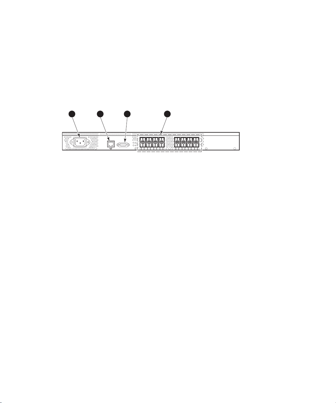
4/8 and 4/16 SAN Switch port side
All L EDs reside on the port side of the switch (see Figure 1). The 4/8 and 4/16 SAN
Switch enclosure uses forced-air cooling, with the fans pushing the air from the nonport
side of the chassis through the enclosure and exhausting at the port side.
See Interpreting LED activity on page 69 for a complete description of switch LEDs.
1
2 3
IOIOI
4
scale: 5/16" = 1"
!
0
4
152
3
8
11
7
6
91310
12
15
14
MRO25019a
1. AC power receptacle 3. Serial port
2. Ethernet port
4. FC port
s(16)
Figure 1 4/8 and 4/16 SAN Switch port side
4/8 and
4/16 SAN Switch nonport side
The non
port side is used solely for airflow and serial number labels. There are two labels
on the rear of the chassis: one is the HP serial number, the other is the switch supplier’s
serial number. The left label also contains the 4/8 SAN Switch or 4/16 SAN Switch
MAC ad
dress and world wide name (WWN).
Activating additional 4/8 and 4/16 SAN Switch ports
The 4/16 SAN Switch models offer 8, 12, or 16 licensed ports. To enable ports
8 through 11, you must purchase and install one or more HP StorageWorks 4-Port
Upgrade Licenses. To enable ports 12 through 15, you must purchase and install a
second HP StorageWorks 4-Port Upgrade License.
To activate additional ports:
1. Use the portshow command to verify the number of p orts licensed on your switch.
The port status output indicates Started and Licensed for enabled ports. See
the Fabric OS command reference manual for specific information on this command.
2. Use the switchshow command to obtain your SAN Switch WWN, which your HP
representative requires to assign a license key.
SAN Switch installation guide
17
Page 18

3. Contact your HP representative to purchase th e HP StorageWorks 4-Port Upgrade
License, part number T4260A.
4. Upon receipt of the HP StorageWorks 4-Port Upgrade License, install the license:
a. Log in to the 4/16 Switch as admin.
b. Issue the licenseadd command, followed by the license key enclosed in
quotation marks. (The license key consists of approximately 16 uppercase
and lowercase letters and numerals.)
NOTE:
Enter the license key exactly as issued. If you enter the key incorrectly,
the license will not function properly.
c. Issue the licenseshow command to verify that the license is valid. If a
licensed product is not displayed, the license is invalid.
NOTE:
It is not necessary to reboot the system. The product is available
immediately after you enter the license key.
5. Configure th
commandloadstheportcode,unliketheportenable command, which enables
the port laser. For example:
portstart 1
6. Issue the portenable command to enable the ports. For example:
portenable 16–31
7. Op tional:
are started.
einactiveports.Issuetheportstart command to start the ports. This
6–31
Issue the portshow command to verify that the newly activated ports
Enabling E_Ports on the 4/8 SAN Switch
The 4/8 SAN Switch requires that you purchase the Full Fabric Upgrade License, part
number T4261A, to enable E_Ports (the 4/16 SAN Switch ships with the Full Fabric
license installed). The switch, by default, cannot be connected to another switch until this
license is installed. Without the license, the switch can still be directly connected to hosts
and storage devices. To install the Full Fabric Upgrade License,usethelicenseadd
command. After it has been installed, the license appears under the licenseshow
command as Full Fabric License and indicates that E_Ports are now automatically
enabled when interswitch links (ISLs) are connected.
18 Overview
Page 19

SAN Switch lice
nsing
SAN Switches o
domain licens
perate differently in the network, depending on which HP StorageWorks
es are installed. The 4/8 Base SAN Switch has no E_Port, unless you
purchase and install the HP StorageWorks 4/8 Full Fabric Upgrade License.
• Full Fabric license— Allows one or more switches to operate within a domain.
All SAN Switc
h Power Pack models ship with this license installed.
To determine the type of license installed on your SAN Switch, issue the licenseshow
command at the command line interface (CLI) prompt. The Full Fabric license is listed as
Fabric lice
nse. A list of all licenses currently installed on the switch is displayed,
as shown in Example 1.
Example 1:
switch:admin> licenseshow
AbbbcDefcQxdezdr:
Web license
Zoning license
Fabric license
Remote switch license
Extended fabric license
Fabric Watch license
Performance Monitor license
Trunking license
Security license
switch:admin>
NOTE:
If the licen
sed feature is displayed, the feature is installed and immediately available.
SAN Switch installation guide
19
Page 20

4/32 SAN Switch models
TheHPStorageWorks4/32SANSwitchmodelsinclude:
• HP StorageWorks 4/32 SAN Switch Base ships with 16 ports activated and
includes Zoning and Advanced Web Tools as standard software components.
• HP StorageW
includes Zo
• HP StorageWorks 4/32 SAN Switch Power Pack ships with 32 ports activated
and includes a Full Fabric license, Advanced Web Tools, and Zoning as standard
software components. It also includes integrated licenses for all optional
management tools (including Advanced Performance Monitoring, ISL Trunking,
Extende
NOTE:
To add ports, see Activating additional 4/32 SAN Switch ports on page 31.
4/32 SAN Switch features
The HP StorageWorks 4/32 SAN Switch provides the following features:
• Air-cooled 1U chassis
• Thirty-two fixed autosensing 1, 2, or 4-Gb/s FC ports with the following
characteristics:
• Automatic negotiation to the highest common speed of all devices connected
to the port
• Port interfaces compatible with SFP transceivers, both SWL and LWL
• Universal and self-configuring ports capable of becoming an F_Port (fabric
enabled), FL_Port (fabric loop enabled), or E_Port (expansion port)
• One RS-232 serial port designed to connect to a DTE port
• One 10/100 Mb/s Ethernet port with an RJ-45 connector
• Two redundant, hot-pluggable, universal AC power supplies
• Three redundant, hot-pluggable fans
orks 4/32 SAN Switch Full ships with 32 ports activated and
ning and Advanced Web Tools as standard software components.
d Fabric and Fabric Watch).
4/32 SAN Switch chassis
This section provides an illustration of the front (port side) and rear (nonport side) panels
of the SAN Switch chassis and identifies the components of each side.
20 Overview
Page 21
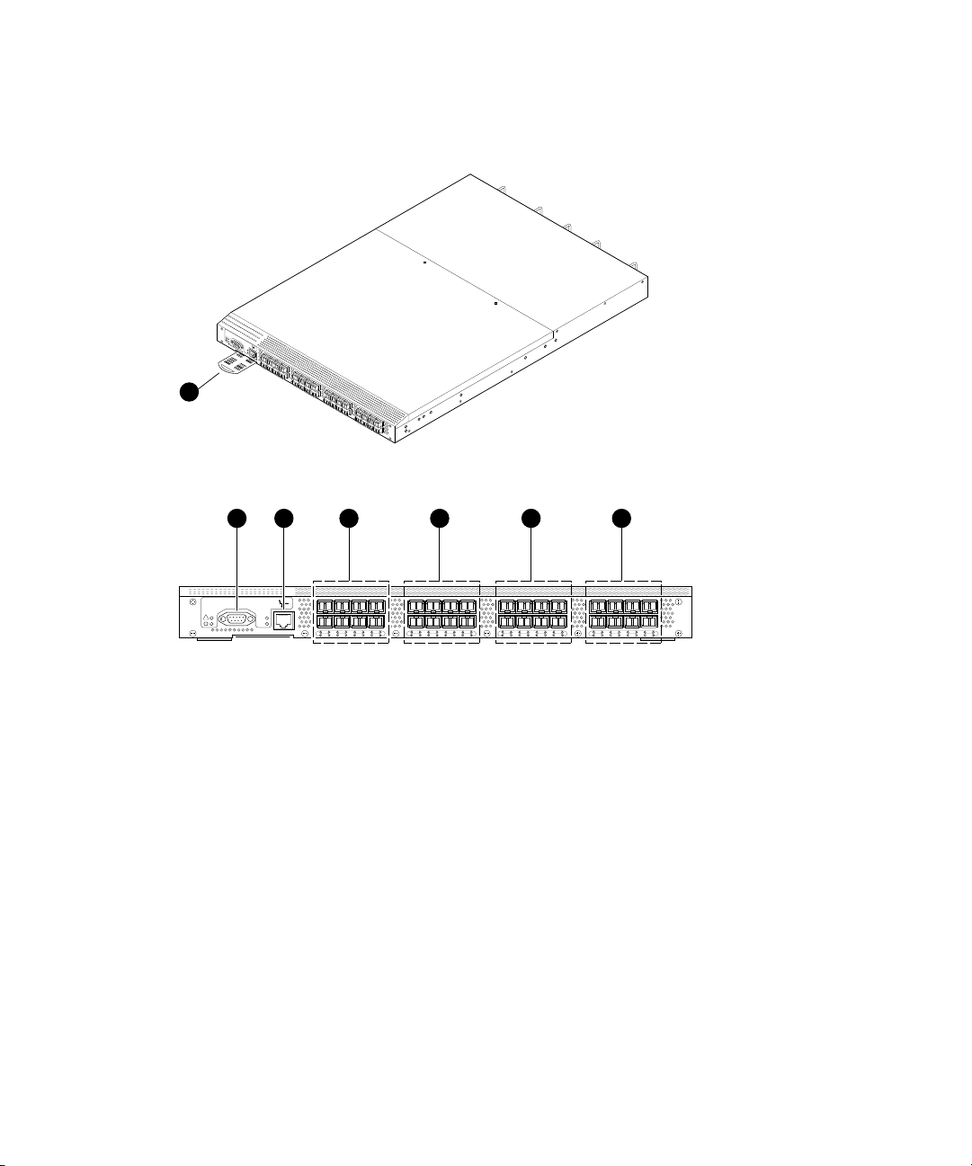
4/32 SAN Switch port side
Figure 2 shows the port side of the 4/32 SAN Switch and identifies the components.
!
IO
IO
I
LNK
SP
D
1
scale: 1/8" = 1"
4 5 6 732
IOIOI
!
LNK
SPD
0
37152
8
11
4
6
91310
12
14
16
19
15
172118
20
22
24
23
252926
28
scale: 5/16" = 1"
1. Switch
ID pull-out tab
3. Ethernet port
2. Serial
4. FC ports 0–7
port
5. FC ports 8–15 6. FC ports 16–23
7. FC por
ts 24–31
Figure24/32SANSwitchportside
27
31
30
MRO25009a
SAN Switch installation guide
21
Page 22
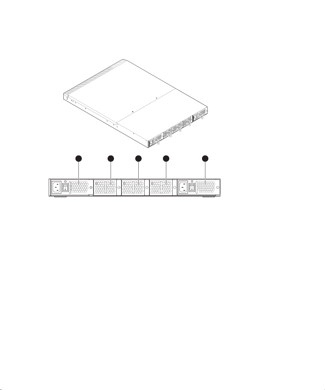
4/32 SAN Switch nonport side
Figure 3 shows the nonport side of the 4/32 SAN Switch, which contains the power
supplies (including the AC power inlet and AC power switch) and fans.
Scale: 1/8" = 1"
3 4 521
MRO25010a
1. Power supply 2
3. Fan 2
5. Power supply 1
2. Fan 3
4. Fan 1
Figure34/32SANSwitchnonportside
Activating additional 4/32 and 4/32B SAN Switch ports
The SAN Switch 4/32 and 4/32B SAN Switches are available with either 16 ports
hrough 1 5) activated for the Base model or 32 ports (0 through 31) activated for
(0 t
the Full model.
To activate additional ports, contact your HP representative to purchase the HP
rageWorks 8-Port Upgrade License, part number T3677A. If your 4/32 SAN Switch
Sto
shipped with 16 active ports, purchase one 8-Port Upgrade License to activate ports 16
through 23; purchase a second 8-Port Upgrade License to activate ports 24 through 31 .
22 Overview
Page 23

NOTE:
Check the port status to determine whether the license is preinstalled. Use the
portshow command for ports 16 through 31. If the port status output indicates
Started and Licensed, all 32 ports are activated.
1. If ports 16 through 31 show no license, you can purchase the HP StorageWorks
8-Port Upgrade License, part number T3677A, from an authorized HP representative.
Your HP representative requires the 4/32 SAN Switch’s WWN in order to assign a
license key. Enter the switchshow command to obtain the WWN of your 4/32
SAN Switch.
2. Install the HP StorageWorks 8-Port Upgrade License. The license key consists of
approximately 16 uppercase and lowercase letters and numerals.
a. Log in to the 4/32 SAN Switch as admin.
b. Enter the licenseadd command, followed by the license key enclosed in
quotation marks.
NOTE:
Enter the license key exactly as issued. If you enter it incorrectly, the
license will not function properly.
c. After entering the license key, use the licenseshow command to verify that
the license is valid. If a licensed product is not displayed, the license is invalid.
NOTE:
After entering a license key, the licensed product is available
immediat
ely.Thesystemdoesnotrequireareboot.
3. Configure the inactive ports. Issue the portstart command to start the ports. This
command loads the port code, unlike the portenable command, which enables
the port laser. For example:
portstart 16–31
4. Issue the portenable command to enable the ports. For example:
portenable 16–31
5. Optional: Issue the portshow command to verify that the newly activated ports
are started.
SAN Switch installation guide
23
Page 24

4/64 SAN Switch models
TheHPStorageWorks4/64SANSwitchmodelsinclude:
• HP StorageWorks 4/64 SAN Switch Base ships with 32 ports activated and
includes Zoning and Advanced Web Tools as standard software components.
• HP StorageWorks
includes Zonin
• HP StorageWorks 4/64 SAN Switch Power Pack ships with 32 ports a ctivated
and includes a Full Fabric license, Advanced Web Tools, and Zoning as standard
software components. It also includes integrated licenses for all optional
management tools (including Advanced Performance Monitoring, ISL Trunking,
Extended Fab
NOTE:
To add ports, see Activating additional 4/64 SAN Switch ports on page 28.
4/64 SAN Switch features
The HP StorageWorks 4/64 SAN Switch provides the following features:
• Air-cooled 2U chassis.
• 64 autosensing 1, 2, or 4-Gb/s Fibre Channel ports with the following
characteristics:
• Automatic negotiation to the highest common speed of all devices connected
to the port
• Port interfaces compatible with SFP transceivers, both SWL and LWL
• Universal and self-configuring ports capable of becoming an F_Port (fabric
enabled), FL_Port (fabric loop enabled), or E_Port (expansion port)
• Three redundant, hot-pluggable fan FRUs.
• Two redundant, hot-pluggable, universal AC power supplies. The unit can run on
one power supply, but HP recommends using both for redundancy.
• Two AC power supply cables
• One RS-232 serial port, designed to connect to a DTE port.
• One 10/100 Mb/s Ethernet port with an RJ-45 connector.
• Three internal temperature sensors.
4/64 SAN Switch Full ships with 64 ports activated and
g and Advanced Web Tools as standard software components.
ric and Fabric Watch).
24
Overview
Page 25

4/64 SAN Switch chassis
This section provides an illustration of the front (port side) and rear (nonport side) of
the SAN Switch c
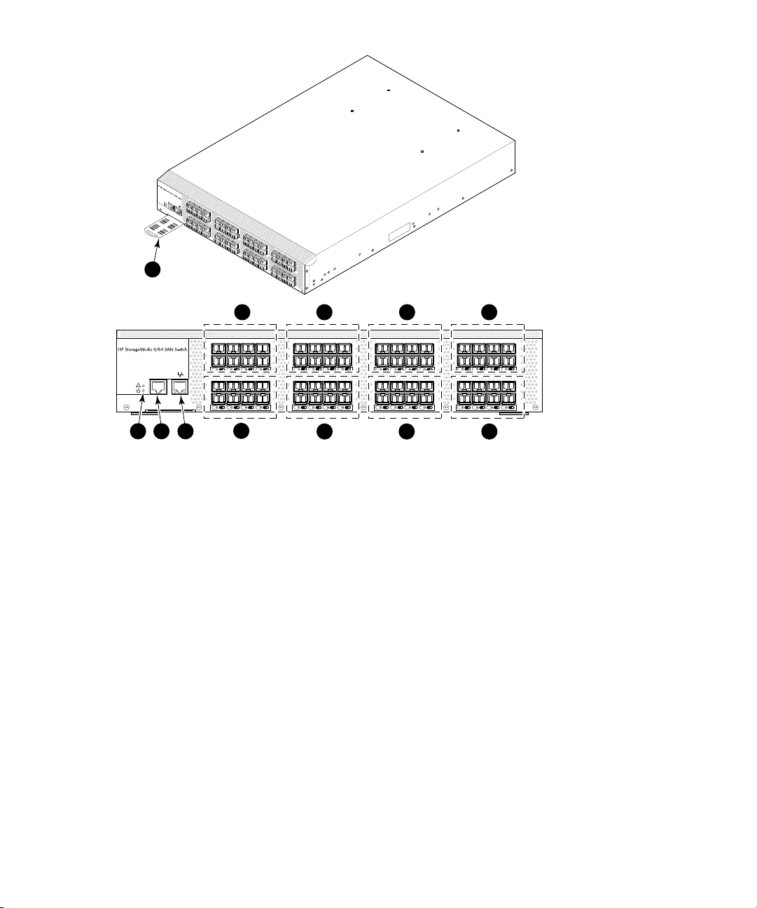
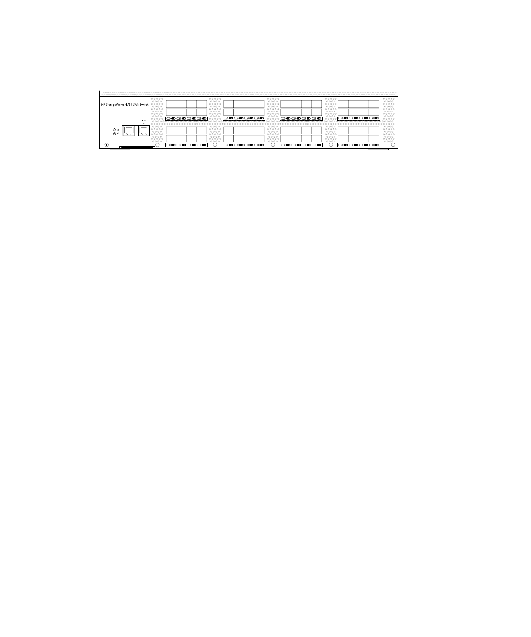
4/64 SAN Switch port side
Figure 4 shows the port side and identifies the components.
hassis.
SAN Switch installation guide
25
Page 26
Scale: 1/8" = 1"
I
O
!
IO
I
0
47
1
5
2
6
3
8
3
2
1
2
3
6
9
3
3
1
3
3
73
1
0
3
4
1
4
8
1
1
3
5
1
5
3
9
1
6
0
4
0
2
0
4
4
1
7
1
1
2
1
4
5
1
8
2
4
2
2
2
4
6
1
9
3
4
34
2
3
4
7
2
4
0
4
8
2
8
5
2
2
5
1
4
9
2
9
5
3
2
6
2
5
0
3
0
5
4
2
7
3
5
1
3
1
5
1
5
0
5
6
6
0
1
5
7
6
1
2
5
8
6
2
3
5
9
6
3
k
c
a
.
r
n
r
i
:
fo
4
N
6
h
/
t
3
g
1
IO
n
r
e
T
l
o
w
N
m
e
r
E
m
c
5
T
s
e
T
m
b
A
u
o
t
m
i
g
x
a
in
t
M
n
u
o
m
5
Scale:
!
2
5/16" = 1"
IOIOI
3
4
0 4 1 5 2 6 3 7
32 36 33 37 34 38 35 39
9
1. Switch ID pull-out tab
6 7
8 12 9 13 10 14 11 15
40 44 41 45 42 46 43 47
16 20 17 21 18 22 19 23
48 52 49 53 50 54 51 55
10 11 12
2. System Status LED (top) & Power LED
(bottom)
3. Serial port 4. Ethernet port
5. FC por
ts 0–7
7. F C p o rt s 1 6 – 23
9. FC po rts 32– 39
11. FC p
orts 48–55
6. FC por
8. FC ports 24–31
10. FC ports 40–47
12. FC ports 56–63
ts 8–15
Figure 4 4/64 SAN Switch port side
8
24 28 25 29 26 30 27 31
56 60 57 61 58 62 59 63
25180a
26 Overview
Page 27
4/64 SAN Switch port numbering
Figure 5 identifies port numbering for the 4/64 SAN Switch.
0123
4567
0 4 1 5 2 6 3 7
32 33 34 35
36 37 38 39
32 36 33 37 34 38 35 39
!
Scale:
5/16" = 1"
IOIOI
Figure 5 4/64 SAN Switch port numbering
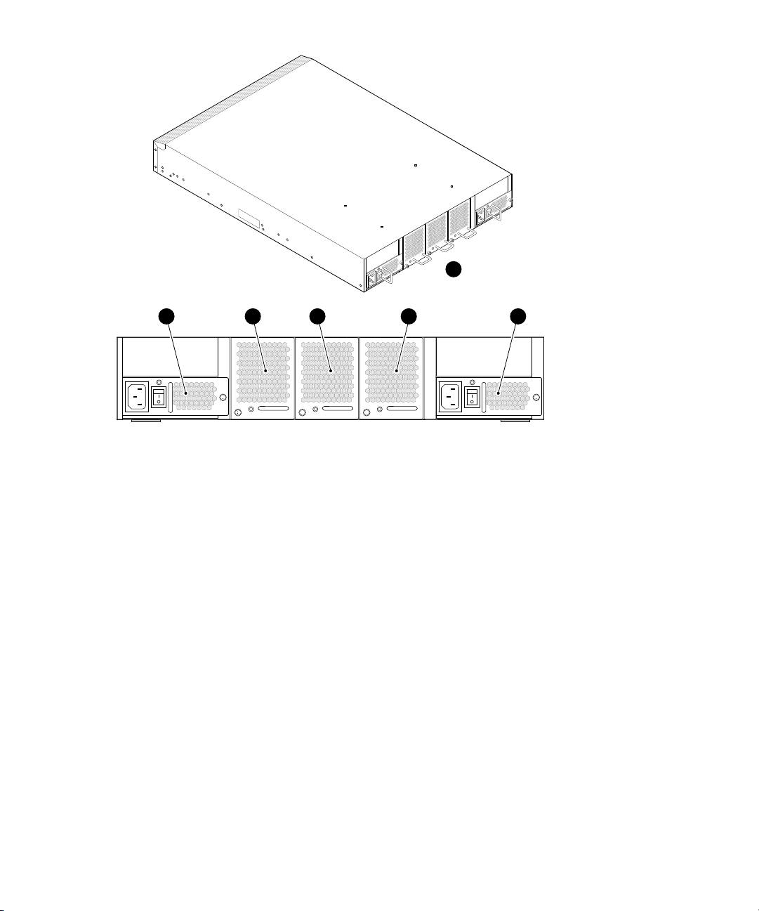
4/64 SAN Switch nonport side
Figure 6 shows the nonport side of the 4/64 SAN Switch, which contains the power
supplies (including the AC power inlet and AC power switch) an d fans.
8 91011
12 13 14 15
8 12 9 13 10 14 11 15
40 41 42 43
44 45 46 47
40 44 41 45 42 46 43 47
16 17 18 19
20 21 22 23
16 20 17 21 18 22 19 23
48 49 50 51
52 53 54 55
48 52 49 53 50 54 51 55
24 25 26 27
28 29 30 31
24 28 25 29 26 30 27 31
56 57 58 59
60 61 62 63
56 60 57 61 58 62 59 63
25181a
SAN Switch installation guide
27
Page 28
Scale: 1/8" = 1"
A
T
T
E
M
N
a
x
T
i
m
m
IO
u
o
m
u
N
n
s
t
:
in
c
r
g
e
w
t
o
l
b
e
e
n
g
5
t
m
h
m
f
o
r
o
r
r
a
1
c
k
3
/
6
4
i
n
.
1
2 3 4
1. Nonport side of switch
3. Fanassembly3 4. Fanassembly2
5. Fan assembly 1 6. Power supply 1
Figure 6 4/64 SAN Switch nonport side
Activating additional 4/64 SAN Switch ports
The 4/64 SAN Switch contains 64 ports, with ports 0 through 31 enabled. To enable
additional ports, you must purchase and install the HP StorageWorks 16-Port Upgrade
e, part number T4411A. The license enables ports in 16-port increments.
Licens
Forexample,toenableports32through47,youmustpurchaseandinstalloneHP
StorageWorks 16-Port Upgrade License. To enable ports 48 through 63, you must install
an addi
For det
guide.
tional 16-Port Upg rade License. Enabling ports on the switch is nondis ruptive.
ailed information on these optional licenses, see the Fabric OS administrator’s
5 6
2. P ower s
upply 2
Scale:
5/16" = 1"
25182a
28 Overview
Page 29

4/32B SAN Switch mod
els
The HP StorageWor
• HP StorageWorks 4/32B SAN Switch ships with 16 ports activated, and includes
a Full Fabric license, Zoning and Advanced Web Tools as standard software
components.
• HP StorageWorks
Fabric and incl
components.
• HP StorageWorks 4/32B SAN Switch Power Pack ships with 32 ports activated,
includes a Ful
software com
management
Extended Fabric and Fabric Watch).
NOTE:
To add ports, see Activating additional 4/32 and 4/32B SAN Switch ports.
ks 4/32B SAN Switch models include:
4/32B Full SAN Switch ships with 32 ports activated, Full
udes Zoning and Advanced Web Tools as standard software
l Fabric license, Advanced Web Tools, an d Zoning as standard
ponents. It also includes integrated licenses for all optional
tools (including Advanced Performance Monitoring, ISL Trunking,
4/32B SAN Switch features
The HP StorageWorks 4/32B SAN Switch provides the following features:
• Air-cooled 1U chassis
• Thirty-two fixed autosensing 1, 2, or 4Gbps FC ports with the following
characteristics:
• Automatic negotiation to the highest common speed of all devices connected
to the port
• Port interfaces compatible with SFP transceivers, both SWL a nd LWL
• Universal and self-configuring ports capable of becoming an F_Port (fabric
enabled), FL_Port (fabric loop enabled), or E_Port (expansion port)
• One RS-232 serial p ort designed to connect to a DTE port, see Serial port
specifications, page 141
• One 10/100 Mb/s Ethernet port with an RJ-45 connector
• Two hot-swappable, redundant power supply/fan assembly units. They are
identical and interchangeable.
4/32B S AN Switch chassis
This section provides an illustration of the front (port side) chassis and identifies the
components.
SAN Switch installation guide
29
Page 30
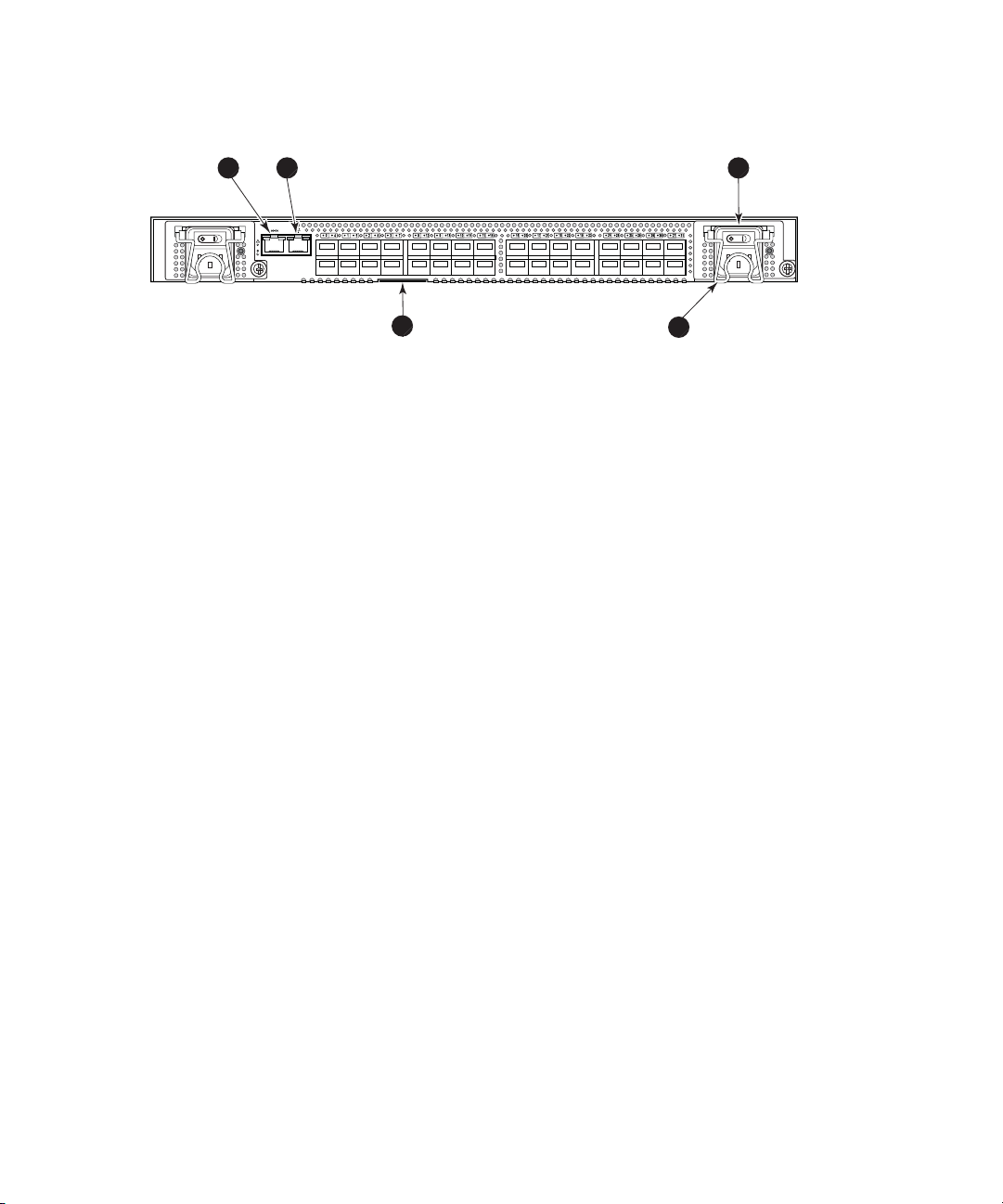
4/32B SAN Switch port side
Figure 7 shows the port side of the 4/32B SAN Switch and identifies components.
1 2 3
5
1. Serial port 4. Power cord retainer
2. Ethernet or c
onsole port
5. Switch ID pul
louttab
3. Power supply/fan assembly
Figure 7 4/32B SAN Switch port side
4
25271a
30 Overview
Page 31

Locating 4/32B SAN Switch FC ports
FC ports are numbered from left to right, in eight-port groups, and are also numbered
on the faceplate, see Figure 8.
25273a
Figure 8 4/3
2B SAN Switch FC ports
Activating additional 4/32B SAN Switch ports
The 4/32B SAN Switch is available with either 16 ports (0 through 15) activated for the
standard model or 32 ports (0 through 31) activated for the Full or Power Pack models.
To activate ad ditional ports, contact your HP representative to purchase the HP
StorageWorks 8-Port Upgrade License, part number T3677A. If your 4/32B SAN Switch
shippedwith16activeports,purchaseone8-Port Upgrade License to activate ports 16
through 23; purchase a second 8-Port Upgrade License to activate ports 24 through 31.
NOTE:
Check the port status to determine whether the license is preinstalled. Use the
portshow command for ports 16 through 31. If the port status output indicates
Started and Licensed, all 32 ports are activated.
See Activating additional 4/32 and 4/32B SAN Switch por ts ,page22forstepson
installing the license and activating ports.
SAN Switch ISL Trunking groups
ISL Trunking is optional HP StorageWorks software that allows you to create trunking
groups of ISLs between adjacent switches. For more information about trunking, see the
Fabric OS administrator’s guide.
If your SAN Switch is licensed for ISL Trunking (for example, Power Pack models ship
with this license), use the trunking groups available on the switch.
SAN Switch installation guide
31
Page 32

NOTE:
The maximum number of ports per trunk for the 4/8 and 4/16 SAN Switches is four.
The FC ports are numbered from left to right in groups of four. This arrangement
indicates the groups of ports that can be used in the same ISL trunking group. The
trunking groups are the t wo or four sets of ports at the top or bottom of the group, as
shown in Figure 5 on page 27.
Optional SAN Switch features
SAN Switches support the following optional software, activated with the p urchase of
alicensekey:
NOTE:
All SAN Switch Power Pack models ship with these licensed options enabled.
• ISL Trunking
• Secure Fabric OS
• Fabric Watch
• Advanced Performance Monitoring
• Extended Fabrics
For detailed information on these features, see the Fabric OS administrator’s guide
for the firmware version you are running.
32 Overview
Page 33

SAN Switch optional port licenses and hardware
Table 2 lists the optional port licenses and hardware kits available for SAN Switches.
Table 2 Optional port licenses and h ardware kits
Option
HP StorageWor
SAN Switch on
HP StorageWorks 8-Port Upgrade License (for 4/32
SAN Switch and 4/32B SAN Switch only)
HP StorageWorks 16-Port Upgrade License (for 4/64
SAN Switch only)
HP Storage
License (for 4/64 SAN Switch only)
HP StorageWorks 4 Gb SW SnglePK SFP Transceiver
Long wavelength 4 Gb SFP, 10 km
Short wa
Long wavelength 2 Gb SFP, 10 km
Long wavelength 2 Gb SFP, 35 km
2 m LC-to-LC multi-mode FC cable
5 m LC-to-LC multi-mode FC cable
15 m LC-to-LC multi-mode FC cable
30 m LC
50 m LC-to-LC multi-mode FC cable
2 m LC-to-SC multi-mode FC cable
5 m LC-to-SC multi-mode FC cable
15mLC-to-SCmulti-modeFCcable
30 m LC-to-SC multi-mode FC cable
LC-to-SC multi-mode FC cable
50 m
*
Pre-merger Compaq part number
ks 4-Port Upgrade License (for 4/8
ly)
Works 64-Port Power Pack Upgrade
velength 2 Gb SFP
-to-LC multi-mode FC cable
Part number
T4260A
T3677A
T4411A
T4412A
A7446B
AE493A
A6515A
A6516A
300836–B21
221692–B21
221692–B22
221692–B23
2–B26
22169
221692–B27
221691–B21
221691–B21
221691–B23
221691–B26
691–B27
221
*
*
*
*
*
*
*
*
*
*
*
SAN Switch installation guide
33
Page 34

NOTE:
To obtain the latest i nformation on hardware and software components, go to the B-Series section of the following web page:
ttp://www.hp.com/go/san.
h
34
Overview
Page 35

2 Installing an d configuring
SAN Switches
This chapter describes the following topics:
•
Shipping carton contents, page 35
•
Installation and safety considerations, page 38
•
Installing the switch as a stand-alone device, page 40
• Installing the switch using the SAN Switch Rack Mount Kit, page 41
•
Cabling and configuring the SAN Switch, page 52
•
Connecting the SAN Switch to the fabric, page 53
Shipping carton contents
Figure 9 and Table 3 identify shipping carton contents for a typical SAN Switch.
1
3
IOIOI
!
k
c
.
ra
:
in
or
h f
/64
t
ION
eng
r 13
l
o
ENT
w
m
cre
m
ATT
m s
be 5
imu
ax
M
nting to
u
mo
2
MRO25011b
Figure 9 SAN Switch shippin g carton contents
SAN Switch installation guide
35
Page 36

Table 3 identifies the carton contents included with your SAN Switch.
Table 3 SAN Switch shipping carton checklist
Number
1
2
3
Description
One SAN Switch Acc
• One 3.0 m (10 ft) RS
removing the ada
• Plenum (not show
the switch to draw cooler air into the switch from outside the rack, rather than
drawing in heated air from within the rack. SAN Switches that require a
plenum include:
—SANSwitch2/16V
— SAN Switch 2/16
—4/8SANSwitch
—4/16SANSwitch
—4/32BSANSwitch
• SAN Switch Rack Mount Kit hardware contained in plastic pouches:
• 14 #8-32 x 3/16-inch Phillips pan-head screws with thread lock for the
SAN Switch 2/32 (requires twelve screws, six per rail)
• 14 #8-32 x 5/16-inch pan-head SEMS screws for use with the 4/8,
4/16, 4/32, 4/32B and 4/64 SAN Switches (All require ten screws
except for the 4/32B SAN Switch which requires six screws)
• Ten #10-32 x 1/2-inch Phillips pan-head screws with captive star
lock-washers
• Eight #10 alignment washers
• Eight #10 adapter washers
• Two 1/4-20 hex nuts with captive star lock-washers
• Two 1/4-inch flat washers
• Four rubber feet for mounting on a flat surface (a lab bench, for example)
• EZSwitchSetup CD
• One set of HP StorageWorks product documentation including Safety Guides,
User License, Read Me First, and Warranty
• For the 4/8 and 4/16 SAN Switches, one country-specific AC power cord
and one PDU power cord (not shown); for the 4/32, 4/32B and 4/64 SAN
Switches, two country-specific AC power cords and two PDU power cords
(not shown)
SAN Switch Rack Mount Kit rail assemblies:
• Two rear mounting brackets
• A right inner rail and a right outer rail
• A left inner rail and a left outer rail
One of the following:
• One HP StorageWorks 4/8 SAN Switch
essories Box containing:
-232 serial cable; convertible to an RJ-45 connector by
pter on the end of the cable
n) — An air duct that attaches to the switch rails, enabling
36
Installing and configuring SAN Switches
Page 37

Number
Description
• One HP StorageWork
• One HP StorageWor
• One HP StorageWo
• One HP StorageWo
s4/16SANSwitch
ks 4/32 SAN Switch
rks 4/32B SAN Switch
rks 4/64 SAN Switch
SAN Switch installation guide
37
Page 38

Installation and safety considerations
Install the switch using one of the following methods:
• As a stand-alone unit on a flat surface. See Installing the switch as a stand-alone
device on pag
• HP highly recommends mounting the switch in one of the following HP customized
racks:
•HPSystem/e
• HP 10000 G2 Series Rack, HP 9000 Series Rack and HP 10000 Series Rack
See Installing the switch using the SAN Switch Rack Mount Kit on page 41 for detailed
instructio
ns.
Electrical considerations
For successful installation and operation of the switch, ensure that the following electrical
requirements are met. For power supply information, see SAN Switch technical
specifications on page 131.
• PrimaryACinput100–240VAC,2.0A,47–63Hz(switchautosensesinput
voltage)
• A correctly wired primary outlet, with a circuit protected by a circuit breaker and
grounded in accordance with local electrical codes
• Adequate supply circuit, line fusing, and wire size, as specified by the electrical
rating on the switch nam e plate
e40.
Rack
Environmental considerations
Before
• To ensu re adequate cooling, install the switch with the nonport side (which
• Verify that a minimum of 24 cubic ft/minute of airflow is available to the air
• Verify that the ambient air temperature does not exceed 40 ºC (104 ºF) while
38
installing the switch:
contains the air intake vents) facing the cool-air aisle.
ke vents on the nonport side of the switch.
inta
the switch is o perating.
Installing and configuring SAN Switches
Page 39

IMPORTANT:
The40ºCvalueappliestotheambientairtemperatureattheairintakeventsonthe
nonport side of the switch. The temperature inside the switch can be up to 80 ºC (176
ºF) during switch operation. If the internal temperature range exceeds the operating
ranges of the components, the LEDs, error messages, and Fabric Watch alerts indicate
a problem. Enter the tempshow or Fabric Watch command to view temperature
status.
NOTE:
For a complete list of environmental considerations, see Table 25 on page 136.
Rack specifications
If you are installing the switch in a rack:
• Plan a rack space that is one rack unit (4.45 cm or 1.75 in) high, 48.3 cm (19
in) wide, and at least 76.2 cm (30 in) deep.
• Verify that the rack is mechanically secured to ensure stability in the event of an
earthquake or other natural disaster.
• Ground all equipment in the rack through a reliable branch circuit connection;
maintainthegroundatalltimes. Donotrelyonasecondaryconnectiontoa
branch circuit, such as a power strip.
• Ensure that airflow and temperature requirements are met on an ongoing basis,
especially if the switch is installed in a closed or multi-rack assembly .
• Verify that the additional weight of the switch does not exceed the rack’s weight
limits or unbalance the rack in any way.
Cooling co
Cooling ai
chassis.
recomme
the rack
Follow
• Install the switch with the nonport side (which contains the air intake vents) facing
• Ensure
• Ensure that a minimum of 24 cu ft/min of airflow is available to the air intake
nsiderations
r is drawn into the switch chassis by the fans mounted on the rear of the
The air is expelled through vents in the front (port side) of the chassis. HP
nds installing the switch so that air intake and exhaust for all comp onents in
are flowing in the same front-to-back direction.
these guidelines to ensure proper airflow and to prevent component overheating:
the cool-air aisle.
that all equipment in the rack forces air in the same direction to avoid
taking in exhaust air.
on the nonport side of the switch.
vents
SAN Switch installation guide
39
Page 40

• Ensure that the ambient air temperature does not exceed 40 ºC (104 ºF) while
the switch is o perating.
NOTE:
Do not block air vents. The switch uses ambient air for cooling.
Installing the switch as a stand-alone device
To install the switch as a stand-alone unit:
1. Unpack the switch and verify tha t all items listed in Shipping carton
contents on page 35 are present.
2. Locate the four rubber feet in the accessory box.
3. Apply the adhesive rubber feet to the switch. The rubber feet help prevent the switch
from sliding off the supporting surface:
a. Clean the indentations at each corner of the bottom of the switch to ensure that
they are free of dust or other debris that might lessen the adhesion of the feet.
b. Withtheadhesivesideagainstthechassis,placeonerubberfootineach
indentation and press into place.
4. Place the switch on a flat, sturdy surface.
5.
Apply power to the switch as described in Powering on and off on page 66.
40
CAUTION:
Do not connect the switch to the network until the IP address is set. For instructions on
setting the IP address, see Cabling and configuring the SAN Switch on page 52.
Installing and configuring SAN Switches
Page 41

Installing the switch using the SAN Switch Rack
Mount Kit
This section provides instructions for installing the SAN Switch in the following HP
custom racks:
• HP System/e Rack
• HP 10000 G2 Series rack, HP 9000 and HP 10000 Series racks
For optimal c
Mount Kit to
rack. In this installation, the port side of the switch is set 12.7 cm (5 in) back from the
edge of the rack, allowing a more gradual bend in the fiber optic cables.
NOTE:
The SAN Swi
Obtain the following items:
• SAN Switch
• Power cables
• #2 Phillips screwdriver
• 7/16-inch wrench or socket
• Plenum (if required, see Table 3) to determine if you need to install a plenum
prior to rack mounting your switch).
• SAN Switch Rack Mount Kit hardware, shown in Table 4 on page 42, which
identifies rails and rail mounting hardware
able management, HP recommends that you install the SAN Switch Rack
allowthenonportsideoftheswitchtoslideoutofthecool-airsideofthe
tch Rack Mount Kit installation requires one technician.
SAN Switch installation guide
41
Page 42

Table 4 SAN Switch Rack Mount Kit hardware
Item
Description
Two rear mounting
A right inner rail and a right outer rail
A left inner rail and a left outer rail
14 #8-32 x 3/16-inch Phillips pan-head screws with
thread lock for use with the SAN Switch 2/32 only.
14 #8-32 x 5/ 16-inch Phillips pan-head SEMS screws
for use with the 4/8, 4/1 6, 4/32, 4/64 and 4/32B
SAN Switches (All require ten screws, except for the
4/32B SAN Switch which requires six screws)
Ten #10-32 x 1/2-inch Phillips pan-head screws with
captive star lock-washers
Eight #10 al
brackets
ignment washers
42
Eight #10 ad
Two 1/4-20 hex nuts with captive star lock-washers
Two 1/4-inch flat washers
Installing and configuring SAN Switches
apter washers
Page 43

CAUTION:
Forproperairflow,theSFPmediasideoftheSANSwitchmustfacetherearoftherack.
To install the switch in a rack:
1.
Verify that the required parts and hardware are available. See Table 3 on page 36.
2. Choose a mounting location for the switch in the rack.
3. Attach the rear mounting brackets to the rear rack uprights:
• For H P 10000 series racks, assemble each of the two brackets with two
#10-32 x 1/2-inch Phillips pan-head screws with captive star lock-washers
and two #10 adapter washers, as shown in Figure 10 on page 43.
• For an HP System/e Rack, install the two rear mounting brackets with
two #10-32 x 1/2-inch Phillips pan-head screws and two #10 alignment
washers, as shown in Figure 11 on page 43.
Figure 10 Installing the rear mounting brackets (HP 10000 seri es
racks)
Figure 11 Installing the rear mounting brackets (HP System/e Rack)
NOTE:
Your SAN Switch Rack Mount Kit contains both left rails and right rails.
SAN Switch installation guide
43
Page 44

4. Assemble the outer rails by completing option a or option b:
a. Attach the left outer rail and the right outer rail to the rear mounting brackets
using two 1/4-20 hex nuts with captive star lock-washers attached loosely,
as shown in Figure 12. Do not tighten the nuts until completing the steps in
Securing the switch to the outer rails, page 50.
Figure 12 In
stalling the outer rails (HP 10000 s eries racks)
44
Installing and configuring SAN Switches
Page 45

b. D e pending on the rack you a re using, complete one of the following tasks:
• For HP 10000 series racks, install two #10-32 x 1/2-inch Phillips
pan-head screws with captive star lock-washers and two #10 adapter
washers in the upper and lower hole locations of the right rail. Then
install two #10-32 x 1/2-inch Phillips pan-head screws with captive star
lock-washers and t wo #10 adapter washers in the upper and lower
hole locations of the l eft rail. See Figure 13.
Figure 13 Assembling t he oute r rails (HP 10000 series racks)
•ForanHPS
ystem/e Rack, install two #10-32 x 1/2-inch Phillips
pan-head screws with captive star lock-washers and two #10 alignment
washers in upper and lower hole locations of the right rail. Then, install
two #10-32 x 1/2-inch Phillips pan-head screws with captive star
lock-washers and two #10 alignment washers in the upper and lower
hole locations of the left rail. See Figure 14 on page 46.
SAN Switch installation guide
45
Page 46

Figure 14 Assembling the o uter rails (HP System/e Rack)
5. D epending on the device model, the SAN Switch Rack Mount Kit requires different
screw types for securing the inner rails. Use Table 5 to determine the number and
screw type for your specific switch.
CAUTION:
Do not use any screws other than those provided. Using longer screws
than those provided can cause damage to internal components.
Table 5 Number of screws required to assemble the inner rails
46
SAN Switch
2/32 N/A
4/8, 4/16
4/32
4/64
4/32B
Installing and configuring SAN Switches
#8-32 x 5/16-inch screws #8-32 x 3/16-inch screws
Ten (Five per rail)
Ten (Five per rail)
Ten (Five per rail)
Six (Three per rail)
12 (Six per rail)
N/A
N/A
N/A
N/A
Page 47

6. Identif y the screw holes to be used on the inner rails designed for the switch:
• To attach the inner rails to the SAN Switch 2/32 use the screw holes
marked 32.
• To attach the inner rails to the 4/8, /16 and 4/32B SAN Switches, use five
screw holes marked 8, and the plenum requires one screw hole m arked 8
and one screw hole marked 16,asshowninFigure 15 on page 48.
• To attach the inner rails to the 4/32 or 4/64 SAN Switch, use the screw
holes marked 16,asshowninFigure 16 on page 48.
7. Assemblethetwoinnerrailstothedeviceusingtheappropriatenumberofscrews
(see Table 5):
• For the 4/8 and 4/16 SAN Switches, secure each inner rail (one on each
side) to the switch using seven #8-32 x 5/16-inch Phillips p an-head SEMS
screws, as shown in Figure 15 on page 48.
• For the 4/32 SAN Switch, secure each inner rail (one on each side) to the
switch using five #8-32 x 5/16-inch Phillips pa n-head screws with thread
lock, as shown in Figure 16 on page 48.
• Forthe4/64SANSwitch,secureeachinnerrail(oneoneachside)to
the switch using five #8-32 x 5/16-inch Phillips pan-head SEMS screws,
as shown in Figure 16 on page 48.
• For the 4/32B SAN Switch, secure each inner rail (one on each side)
to the switch using six #8-32 x 5/16-inch Phillips pan-head screws with
thread lock.
NOTE:
For integration in a cabinet, tighten the #8-32 x 5/16-inch Phillips
pan-head SEMS screws and torque between 6 and 8 inch-pounds.
SAN Switch installation guide
47
Page 48

8. If you are installing the 4/8, 4/16 or 4/32B SAN Switch, verify that a plenum (an
air duct that attaches to the switch rails, enabling the switch to draw cooler air into
the switch from outside the rack, rather than drawing in heated air from within the
rack.) is preinstalled, as shown in Figure 15.
If not installed, see Installing the Plenum (if required), page 49 to install a plenum
on the 4/8, 4/16 or 4/32B SAN Switch.
If not installing one of the devices listed in step 8, go to Securing the switch to the
outer rails, page 50 to complete the rack mount procedure.
1
2
3
A
T
T
E
M
N
a
T
xi
I
m
m
O
o
u
N
u
m
n
s
:
tin
cre
g t
w
o
le
b
e
ng
5
th
m
fo
m
r ra
or
1
c
3/
k
6
4 in
.
IO
I
O
I
!
25052a
Figure 15 At
taching the inner rails to the 4/8 or 4/16 SAN Switch
1. Plenum 2. SAN Switch
3. Two screws for attaching the plenum
to the rails
!
IOIOI
LNK
SPD
MRO25018b
48
Figure 16 Attac h ing t he inner rails to t he 4/32 or 4/64 SAN Switch
Installing and configuring SAN Switches
Page 49

Installing the Plenum (if required)
If installing one of the following SAN switches only, you must install the plenum that
ships in the accessory kit with the rack mount hardware:
• 4/8 SAN Switch
• 4/16 SAN Switch
• 4/32B SAN Switch
To install th
1. Place the device (with inner rails attached) on a flat surface, see Figure 17.
2. Obtain the plenum and four 8-32 x .312 Phillips Pan-head SEMs screws from the
3. For each in
CAUTION:
Verify that the open end of the plenum faces the rear of the switch. For example, when
installe
panel of the switch on the other.
eplenum:
accessory kit.
ner rail (Left and Right)useonescrewholemarked8 and one screw
hole marked 16 to attach the plenum.
d properly you should see the plenum’s air vent holes on one side, and the front
SAN Switch installation guide
49
Page 50

NOTE:
Figure 17 illustrates how to attach the plenum to the 4/8 or 4/16 SAN Switch
specifically. If installing the plenum on the 4/32B SAN Switch, the procedure and
figure also applies.
1
2
3
A
T
T
E
M
N
a
T
x
im
I
m
O
o
u
N
u
m
nt
s
:
in
cr
g
e
t
w
o
le
be
ng
5
th
m
fo
m
o
r
r
r
a
1
c
3
k
/
6
4 in
.
I
O
I
O
I
Figure 17 At taching the Plenum to the 4/8 or 4/16 SAN Switch
1. Plenum 2. SAN Switch
3.Twoscrewsforattachingplenumtorails
Securing the switch to the outer rails
To secure the switch to the outer rails:
1. Insert the switch with the attached inner rails into the outer rails.
NOTE:
This step applies to installing a switch in HP 9000 Series, HP 10000
Series or HP System/e racks.
2. Insert the device into the rack and install (2) #10-32 x 1/2-inch Phillips pan-head
screws with captive star lock washers with one on each side. See Figure 18 and
Figure 19.
!
25052a
50
Installing and configuring SAN Switches
Page 51

Figure 18 Securing the switch (in HP 9000 Series or HP 10000 S eries
Racks)
Figure 19 Securing the switch ( in an HP System/e rack)
3. Tighten the hex nuts installed earlier. See step 4a, page 44.
NOTE:
To uninstall a switch, remove the middle #10-32 x 1/2-inch Phillips pan-head screw
with captive star lock-washer from either side of the rack uprights.
This completes the rack mount procedure.
SAN Switch installation guide
51
Page 52

Cabling and configuring the SAN Switch
The SAN Switch must be configured to ensure correct o peration with a network and
fabric. For instructions on configuring the switch to operate in a fabric containing
switches from other vendors, see the Fabric OS administrator’s guide.
For more information about the commands used in this procedure, see the Fabric OS
command referenc
NOTE:
All supp orting Fabric OS documentation is accessible from the B-Series switches link
on the following web site: h
Recommendations for cable management
Before installing the switch, plan the rack space required for cable management based
on the following HP recommendations:
• Leave enough space to allow for the fact that the minimum bend radius for a
50-micron cable is 2 inches under full tensile load and 1.2 inches with no
tensile load.
• Leave at least 1 m (3.28 ft) of slack for each port cable. This provides room to
remove and replace the switch, allows for inadvertent movement of the rack, and
helps prevent the cables from being bent to less than the minimum bend radius.
• If you are using ISL Trunking, consider grouping cables by trunking groups. The
cables used in trunking groups must meet specific requirements, as described in
the Fabric OS administrator’s guide.
• For easier maintenance, label the fiber optic cables and record the devices
to which they are connected.
• Keep LEDs visible by routing port cables and other cables away from the LEDs.
• Do not use tie wraps on fiber optic cables; tie wraps are easily overtightened
and can damage the optic fibers. HP recommends using velcro straps to secure
and organize fiber optic cables.
emanualfor the Fabric OS version running on your switch.
ttp://www.hp.com/go/san.
52
Installing and configuring SAN Switches
Page 53

Connecting the SAN Switch to the fabric
Connecting the SAN Switch to the fabric involves the following steps:
1.
Obtain requir
2.
Make a serial connection on page 53
3.
Apply power to the switch and log in on page 56
4. Set the IP address on page 57
5.
Create an Ethernet connection on page 58
6.
Modify the
7.
Install the SFP transceivers on page 59
8.
Connect the cables on pa ge 60
9.
Verify t
10.
Back up the configuration on page 60
11.
Set the switch date and time on page 61
12.
13.
ronize the local time with an external source on page 61
Synch
Set the time zone on page 62
Obtain required items
ed items on page 53
FC domain ID (optional) on page 58
he configuration on page 60
To configure the SAN Switch for use in a network, ensure that you have the following:
• SAN Switch installed and connected to a power source
• Workstation with an installed terminal emulator, such as HyperTerminal
• Access to an FTP server to back up the switch configuration
• Unused IP address and corresponding subnet mask and gateway address
• Serial cable (supplied with switch)
• Ethernet cable
• SFP transceivers and compatible cables, as required
Make a serial connection
o make a serial connection through the SAN Switch serial port:
T
1. Insert the serial cable into the serial port on the switch.
2. Connect the serial cable to an RS-232 serial port on the workstation, as shown
in Figure 20.
SAN Switch installation guide
53
Page 54

NOTE:
IftheserialportontheworkstationusesanRJ-45connectorinsteadof
an RS-232 connector, remove the adapter on the end of the serial cable
and insert the exposed RJ-45 connector into the RJ-45 serial port on
the workstation.
IO
I
O
!
I
.
:
rack
in
N
for
th
IO
T
r 13/64
N
TTE
screw leng
A
m
u
be 5mm o
im
ng to
Max
nti
mou
0014b
Figure 20 Connecting t he serial cabl e
54
Installing and configuring SAN Switches
Page 55

NOTE:
Figure 20 shows the 4/ 16 SAN Switch; however, this procedure is similar
for all SAN Switches.
3. Close any serial communication programs running on the workstation.
4. Open a terminal emulator application (such as HyperTerminal on a PC or TERM in
a UNIX environment) and configure the application as follows:
• In a Windows 95, 98, 2000, or NT environment:
•9600bitspersecond
• 8 data bits
• No parity
•1stopbit
• No flow control
• In a UNIX environment, enter the following at the prompt:
tip/dev/ttyb –9600
SAN Switch installation guide
55
Page 56

Apply power to t
Once a serial connection is established, apply power to the switch:
1. Connect the power cord to a power inlet on the switch and a power source, as
shown in Figur
NOTE:
The 4/32, 4/32
The 4/8 and 4/16 SAN Switches use one power cord.
Figure 21 Connecting the power cord
he switch and log in
e21.
B and 4/64 SAN Switch models use two power cords.
IO
I
O
!
I
ck
:
ra
in.
N
for
/64
IO
T
ength
or 13
EN
m
TT
5m
A
m screw l
be
imu
to
ax
M
nting
mou
0015b
56
NOTE:
To protect against AC failure on the 4/32, 4/32B and 4/64 SAN Switch
models, connect each power cord to outlets on separate circuits. Verify
that the cords have a minimum service loop of 6-inches to avoid stress.
2. To power on, set the two AC switches to the ON position (I).
IMPORTANT:
The 4/8 and 4/16 SAN Switches utilize one power switch. The 4/32,
4/32B and 4/64 SAN Switches utilize two power switches.
The power supply LED lights green and the switch runs the power-on self test (POST).
The switch requires at least three minutes to boot and complete POST.
3. After POST and the boot process are completed, verify that the System Status and
System Power LEDs light green.
Installing and configuring SAN Switches
Page 57

4. When the terminal emulator application, which uses a serial connection, stops
reporting information, press Enter to display the login prompt.
5. Log in using the administrative account; the logon is admin and the default
password is password. Create up to two simultaneous admin sessions and four
user sessions.
For more details, see the Fabric OS administrator’s guide and the Fabric OS
command reference manual for the Fabric OS running on your switch.
Set the IP address
By default, the
information w
1. Enter ipaddrset at the terminal emulator application prompt.
2. Enter the IP addressing information, as prompted.
3. O ptional: Verify that the address is correct by issuing the ipaddrshow command
at the promp
4. Record the IP address on the label located on the port side of the chassis.
For the 4/32, 4/32B and 4/64 SAN Switches, record the IP address on the
pull-out t
locate the pu ll-out tabs.
5. If the serial port is no longer required, log out of the serial console, remove the serial
cable, and replace the safety plug in the serial port.
IP address is set to 10.77.77.77. To replace the default IP addressing
ith the information provided by your network administrator:
t.
ab on the port side of the switch. See Figure 2, Figure 7 or Figure 4)to
SAN Switch installation guide
57
Page 58

Create an Ether
To create an Ethernet connection:
1. Connect an Ethernet cable to the Ethernet port and to the workstation, or to an
Ethernet netw
NOTE:
Figure 22 show
for all SAN Sw
Figure 22 C o nnecting the Ethernet cable
Once the Ethernet cable is connected, access the switch remotely via the CLI or the
integrated Advanced Web Tools GUI software.
2. Log in to the switch via Telnet, using the admin account.
net connection
ork containing the workstation, as shown in Figure 22 on page 58.
s the 4/16 SAN Switch; however, this procedure is similar
itches.
IO
I
O
!
I
:
in.
N
for rack
th
IO
T
or 13/64
EN
crew leng
TT
5mm
A
um s
im
to be
ax
ng
M
nti
mou
0016b
Modify the FC domain I D (optional)
You can modif y the FC domain ID. The default FC domain ID is 1. If the switch is not
powered on until after it is connected to the fabric, and the default FC domain ID is
already in use, the domain ID for the new switch is automatically reset to a unique value.
If the switch is connected to the fabric after it has been powered on, and the default
domain ID is already in use, the fabric segments.
To determine the domain IDs that are currently in use, issue the fabricshow command.
The number of domains is determined by your domain fabric licensing.
To modify the domain ID:
1. Issue the switchdisable command to disable the switch.
2. Issue the configure command. The prompts display sequentially: enter a new
value or press Enter to accept each default value.
58
Installing and configuring SAN Switches
Page 59

3. At the Fabric Parameters prompt, enter y and press Enter:
Fabric Parameters (yes, y, no, n): (no) y
4. Enter a unique domain ID, such as the domain ID used by the previous switch, if
it is still available:
Domain: (1..239) [1] 3
5. Respond to the remaining prompts or press Ctrl+D to accept the default settings.
6. Issue the switchenable command to re-enable the switch.
7. Optional: Specify any custom status policies:
a. Issue the switchstatuspolicyset command. This command sets the
policy parameters that determine the overall switch status.
b. Customize the status policies.
To deactivate the alarm for a particular policy, enter 0 at the prompt for that policy.
InstalltheSFPtransceivers
The SAN Switch does not ship with SFPs. For a list of supported SFPs, see Table
2 on page 33.
The ports sele
these requirements, see the ISL Trunking chapter in the Fabric OS administrator’s guide.
To install the SFP transceivers:
1. Position the
latching mechanism clicks. The transceivers are keyed to ensure correct orientation.
If the transceiver does not install easily, make sure it is oriented correctly.
For instructions specific to the transceiver you are using, see the transceiver
manufacturer’s documentation.
2. Repeat ste
cted for use in trunking groups must meet specific requirements. For a list of
transceiver so that it is oriented correctly and insert it into a port until the
p1for the remaining ports, as required.
SAN Switch installation guide
59
Page 60

Connect the cab
CAUTION:
The minimum bend radius for a 50-m icron cable is 2 inches u nder full tensile load and
1.2 inches with no tensile load. Because they are easily overtightened, HP does not
recommend tie wraps for optical cables.
To connect the cables to the SFP transceivers:
1. The cable connectors are keyed to ensure correct orientation. Orient a cable
connector so that the key (the ridge on the side of the connector) aligns with the
slot in the transceiver, a nd insert the cable into the transceiver until the latching
mechanism clicks. If a cable does not install easily, make sure it is correctly oriented.
For detailed instructions on the cable type, see the cable manufacturer’s
documentation.
2. Repeat Step 1 for the remaining transceivers, as required.
The cables used in trunking groups must meet specific requirements. For a list of these
requirements, see the Fabric OS administrator’s guide.
les
Verify the configuration
To confirm that the switch is configured and ready for use:
1. Check the LEDs to verify that all components are functional. For information about
LED patterns, see Interpreting LED activity on page 69.
2. Issue the switchshow command from the workstation. This command provides
information about the switch and port status.
3. Issue the fabricshow command from the workstation. This command provides
general information about the fabric.
Back up the configuration
HP recommends regular backups to ensure that a recent configuration is available.
To back up the switch configuration to an FTP ser ver:
1. Issue the configupload command.
2. Follow the prompts.
The command uploads the switch configuration to the server, making it available for
downloading to a replacement switch, if necessary. For detailed instructions on backing
up the configuration, see the Fabric OS administrator’s guide.
60
Installing and configuring SAN Switches
Page 61

Set the switch d
The date and time switch settings are used for logging events. Switch operation does
not depend on the date and time ; a switch with an incorrect date a nd time value still
functions pro
You can synchronize the local time of the principal or primary Fabric Configuration
Server (FCS) switch with that of an external Network Time Protocol (NTP) server.
Tosetthedateandtimeforaswitch(seeExample2followingtheprocedure):
1. Log in to the s
ate and time
perly.
witch as admin.
2. Enter the da
date “MMDDhhmm [CC]YY”
The values represent the following:
• MM is the mon
• DD isthedate(01 – 31).
• hh is the hour (00 – 23).
• mm is minut
• CC is the century (19 – 20).
• YY is the year (00 – 99).
Year valu
are inter
Time or t
Example 2:
switch: admin> date
Fri May 5 21:50:00 UTC 1989
switch:admin>
switch:admin> date “0624165203”
Tue Jun 24 16:52:30 UTC 2003
switch:admin>
te command at the CLI prompt, using the following syntax:
th (01 – 12).
es (00 – 59).
es greater than 69 are interpreted as 1970–1999; year values less than 70
preted as 2000–2069. The date function does not support Daylight Savings
ime zones. Reset times for Daylight Savings Time or time zones manually .
Synchronize the local time with an external source
To synchronize the local time of the principal or primary FCS switch with that of an
external NTP server:
1. Log in as admin.
2. Issue the tsclockserver [ipaddr] command.
The ipaddr variable represents the IP address of the NTP server that the switch can
access. This argument is optional; by default, its value is LOCL (see Example 3) .
SAN Switch installation guide
61
Page 62

Example 3:
switch:admin> tsclockserver
LOCL
switch:admin> tsclockserver 132.163.135.131
switch:admin>
Set the time zone
To set the time zone
1. Log in as admin.
2. Issue the following tstimezone command:
tstimezone[houroffset][minuteoffset]
• For Pacific Standard Time, enter tstimezone –8,0.
•ForMountainSt
• For Central Standard Time, enter tstimezone –6,0.
• For Eastern Standard Time, enter tstimezone –5,0.
The default ti
eight hours ahead of Pacific Standard Time. The parameters listed do not apply
if the time zone of the switches has already been changed from the default (eight
hours ahead of PST).
See the tstimezone command in the Fabric OS command reference manual for
more detail
3. Repeat step 1 and step 2 on all switches for which the time zone needs to be set.
Thetimezoneissetonlyonce;thevalueisstoredinnonvolatilememory.
For U.S. tim
the tstimezone command.
:
andard Time, enter tstimezone –7,0.
me zone for switches is Universal Time Conversion (UTC), which is
ed information about the command parameters.
ezones,Table 6 on page 63 provides the correct offset parameters for
62
Installing and configuring SAN Switches
Page 63

Table 6 Time zone command values
Local time
Atlantic Standar
Atlantic Daylight
Eastern Standard
Eastern Daylight
Central Standard
Central Daylight
Mountain Stan
Mountain Daylight
Pacific Standard
Pacific Daylight
Alaskan Standard
Alaskan Daylight
Hawaiian St
d
dard
andard
tstimezone parameter
–4,0
–3,0
–5,0
–4,0
–6,0
–5,0
–7,0
–6,0
–8,0
–7,0
–9,0
–8,0
–10,0
SAN Switch installation guide
63
Page 64

64
Installing and configuring SAN Switches
Page 65

3ManagingSANSwitches
This chapter describes the following topics:
•
Powering on and off, page 66
•
SAN Switch manag em ent features, page 67
•
Managing SAN Switches from a single management station,page67
•
Interpreting LED activity, page 69
•
4/8 and 4/16 SAN Switch LEDs, page 69
•
4/8 and 4/16 SAN Switch LED patterns, page 70
•
4/32SANSwitchportsideLEDs, page 74
•
4/32 SAN Switch nonport side LEDs,page78
•
4/64 SAN Switch port side LEDs, page 79
•
4/64 SAN Switch nonport side LEDs, page 82
•
4/32B SAN Switch LEDs, page 85
•
POST and boot specifications, page 88
•
Interpreting POST results,page89
•
Diagnostic tests, page 89
SAN Switch installation guide
65
Page 66

Powering on and off
The following sections provide information on powering specific SAN Switch models
on and off.
4/8 and 4/16 SAN Switch models
To power on:
1. Connect one end of the power cord to the AC inlet on the switch; connect the
other end to a power source.
2. Set the AC power switch to I.
The switch runs POST each time it is powered on, reset, or rebooted. POST requires
approximately three minutes.
To power off:
1. Set the AC power switch to O.
2. Remove the power cords from the power sources.
NOTE:
Removing all power from the switch triggers a system reset. All devices are returned to
their initial state the next time the switch is powered on.
4/32, 4/32B and 4/64 SAN Switch models
Connect one or both power cords to the AC power inlets on the switch; connect the other
end to a power source.
To power on, set both AC power switches to I. Power is supplied to the switch as soon
as the first power supply is connected and powered on.
To power off, set both AC power switches to O and remove the AC power cord from
the power source.
NOTE:
Removing all power from the switch triggers a system reset. All devices are returned to
their initial states the next time the switch is powered o n.
66
Managing SAN Switches
Page 67

SAN Switch managem
ent features
SAN Switches use b
port status, and debug the switch. Table 7 lists the management tools available.
When running IP over FC, these management tools must be supported by both HBA and
HBA drivers. For a list of supported HBAs, see the HP StorageWorks SAN design guide:
h
ttp://www.hp.com/go/sandesignguide.
Table 7 Manageme
Management tool
CLI—Uptotwoadminsessionsand
four user sessions simultaneously
Advanced Web Tools—Forinformation,
refer to the Web Tools administrator’s
guide for the Fabric OS version running
on your switch.
Standard SNMP applications—For
information, refer to the Fabric OS MIB
reference manual for the Fabric OS
version running on your switch.
Managemen
refer to the Fabric OS administrator’s
guide and the Fabric OS command
referen
version
tServer—Forinformation,
ce manual for the Fabric OS
running on your switch.
uilt-in management tools to help you monitor fabric topology, check
nt tools
Out-of-band support
Ethernet or serial connection
Ethernet connection
Ethernet connection
Ethernet connection Native in-band
In-band support
IP over FC
IP over FC
IP over FC
interface (over HBA
only)
Managing SAN Switches from a single management
station
A management station connected to one switch via Ethernet can also be used to manag e
other switches connected to the first switch via FC. To do so, set the gateway address
of the first switch to the gateway address of the subnet that the first switch resides on.
Then, set the FC gateway address of each of the other switches to the FCIP address of
the first switch. (See Table 8 for an example of address sets for a management station
with three switches).
NOTE:
The disadvantage of this method is that the management station can only communicate
with the switches.
SAN Switch installation guide
67
Page 68

Table 8 Example of a set of gateway addresses
Connection
type
Ethernet
FCIP 192.168.65.09 192.168.65.10 192.168.65.11 192.168.65.12
Gateway 192.168.1.10
Management
1st switch 2nd switch 3rd switch
station
192.168.1.099 192.168.1.10
Any, but itself
204.1.1.11 204.1.1.12
192.168.1.10 192.168.1.10
68
Managing SAN Switches
Page 69

Interpreting LED activity
System activity and status can be determined through the LEDs on the switch. There are
three possibl
e LED states that display either green or amber:
• Asteadylight
• Aflashinglight
• No light
LEDs display either green or amber colors. A steady green light indicates a healthy
state. Sometimes, the LEDs flash any of the colors during boot, POST, or other diagnostic
tests. This is normal; it does not indicate a problem unless the LEDs do not indicate a
healthy sta
te after all boot processes and diagnostic tests are complete.
4/8 and 4/16 SAN Switch LEDs
The LEDs are shown in Figure 23.
Figure 23 shows the LEDs on the port side of the 4/16 SAN Switch.
1
3
2
IOIOI
4
scale: 5/16" = 1"
!
0
4
152
3
6
12
8
7
91310
11
15
14
5 6
1. Ethernet Link LED 2. Ethernet Speed LED
3. System Status LED
5. Power Status LED
4. Port
6. Port Speed LEDs
Status LEDs
Figure 23 4/8 and 4 /16 SAN Switch LED locations
0017b
SAN Switch installation guide
69
Page 70

4/8 and 4/16 SAN Switch LED patterns
Table 9 and Table 10 on page 71 summarize LED locations, colors, and recommended
actions.
Power Status LED patterns
The system and power LED patterns are described in Table 9.
Table 9 4/8 and 4/16 SAN Switch LED patterns
LED name
Power
Status LED
LED colo r Hardware status Recommended action
No light
Steadygreen Switchisonandpowersupplyis
Switch is off or power supply
failed.
functioning properly.
Verify that switch is on and has
completed booting.
No action required.
70
Managing SAN Switches
Page 71

4/8 and 4/16 SAN Switch system Status LED patterns
The system status LED patterns are described in Table 10.
Table 10 System status LED patterns during normal operation
LED n ame
System Status
LED
LED color Hardware status Recommended action
No light
Steady green Switch is operational. No action required.
Slow flashing
green (1
second on,
1 second off)
Amber
Switch is off,
or boot failed
One or both of the following are
true:
Oneormoreenvironmental
ranges were exceeded.
Error log contains one or more
port diagnostic error messages.
Switch is faulty or initializing. Wait a few moments to verify that the
boot is not complete,
.
Verify that sw
completed boo
Check environmental conditions,
error log, Port Status LEDs, SFPs,
cables, and loopback plugs.
Correct error condition.
Clear error log.
Rerun diagnostics to verify fix.
switch is not initializing.
itch is on and has
ting.
SAN Switch installation guide
71
Page 72

4/8 and 4/16 SAN Switch port LED pat terns
Each port includes two LEDs: a Port Speed indicator and a Port Status indicator. Table
11 describes the LED locations, colors, and recommended actions.
Table 11 Port L
LED n ame
Port Status
ED p atterns during normal operation
LED color Hardware status Recommended action
No light No power or signal
carrier(SFPorcable)
detected.
Check SFP and cable.
Steady green Port is online
Slow flashing
green (1
second on, 1
second off)
ashing
Fast-fl
green (1/4
don,1/4
secon
d off)
secon
Flickering green
Steady amber Port is receiving light or
Slow-flashing
amber (1
second on, 1
second off)
(connected to external
device) but has no
traffic.
Port is online but
segmented, indicating
a loopback cable or
incompatible switch.
Port is in internal
loopback (diagnostic).
Port is online with traffic
flowing through it.
signal carrier, but is not
yet online.
t is disabled as the
Por
sult of diagnostics
re
portdisable
or
mmand.
co
all ports are
If
low-flashing amber,
s
he switch may be
t
disabled.
No action required.
Verify that the correct device is connected
to the port and that the switch a nd port
settings are correct.
No action required.
No action required.
No action required.
ble the port using the portenable
Ena
mmand; see the Fabric OS command
co
ference guide for more information.
re
If all ports are slow-flashing amber, enable
the switch (switchenable command ).
72
Fast-flashing
amber (1/4
second on, 1/4
second off)
Alternating
green and
amber
Managing SAN Switches
Port is faulty.
Port is bypassed.
Check the Port Status LEDs, error log, SFP,
and cable or loopback plug.
Cleartheerrorlog.
Rerun the diagnostics to verify that the error
condition is fixed.
Check configuration of FC loop.
Page 73

LED n ame
Port Speed
LED color Hardware status Recommended action
Steady green,
amber off
Green off,
amber off
Green off,
steady amber
Port is transmitting or
receiving at 2 Gb/s.
Port is transmitt
receiving at 1 Gb/s.
Port is transmitting or
receiving at 4 Gb/s.
ing or
No action required.
No action require
No action required.
d.
SAN Switch installation guide
73
Page 74

4/8 and 4/16 SAN Switch Ethernet LED patterns
Each Ethernet port has two LEDs d escribed in Table 12.
Table 12 Ethernet LED patterns
LED name
LED color Hardware sta t
us
Recommended a
ction
No light
Steady green
Steady amber Link is valid. No action required.Ethernet Link
Blinking amber
Port speed is 10 M b/s.
Port speed is 100 Mb/s.
Traffic is flowing.
4/32SANSwitchportsideLEDs
The 4/32 SAN Switch has the following port side LEDs:
• System Stat
• Power Status
• Port Status
• Port Speed
Figure 24 describethelocationsoftheportsideLEDs.
us
No action required.Ethernet Speed
No action required.
No action required.
74
Managing SAN Switches
Page 75

IOIOI
!
LNK
SPD
0
4
152
3
6
12
8
7
91310
11
14
20
16
15
172118
19
22
28
24
23
252926
27
31
30
scale: 5/16" = 1"
1
2
3
IOIOI
!
4 5
1. System Status LED
3. Top port LEDs (0 through 3)
5. Speed L
ED
LNK
SPD
0
1
4
2
5
6
6 7
2. Link LED
4. Power Status LED
6. Port St
atus LEDs
3
7
8
MRO25012a
7. Port Speed LEDs 8. Bottom port LEDs (4 through 7)
Figure 24 4/32 SAN Switch port side LEDs
SAN Switch installation guide
75
Page 76

Table 13 describes the 4/32 SAN Switch port s ide LEDs.
Table 13 4/32 SAN Switch port side LED patterns
LED n a me
Power Status
System Status
LED color Hardware status Recommended action
No light
Steady green Switch is on and p
No light
Steady green System is on and power supplies
Steady Amber
(for more tha
5seconds)
Flashing amber
or green
No light
Steady green
Switch is off or there is an internal
power supply failure.
ower supplies
are functioning
System is off, boot is not complete,
or boot failed.
are functioning properly.
Boot failed and system is faulty.
n
A number of things can cause this
status, including a single power
supply failure, a fan failure, or an
environmental problem.
Port speed is 10 Mb/s.
Port spee
properly.
dis100Mb/s.
Verify that the system is on. If the
system is on, the unit is faulty.
Contact HP Technical Support.
No action requir
Verify that the system is on and
has finished booting.
No action required.
Connect a seri
system.
Reboot the sy
Check the fai
the system c
Contact HP Te
Check the management interface
andtheerrorlogfordetails
on the cause of the status.
Contact HP Technical Support,
if necessary.
No action required.Ethernet Speed
No action required.
ed.
al cable to the
stem.
lure indicated on
onsole.
chnical Support.
76
Ethernet Link
Port Speed
Managing SAN Switches
No light There is no Ethernet link.
Steady amber There is no Ethernet link. No action required.
gamber
Flashin
or no lig
No light
Steady green
Steady amber
ht
There is link activity (traffic).
Port is transmitting or receiving a t
1Gb/s.
Port is transmitting or receiving a t
2Gb/s.
Port is transmitting or receiving a t
4Gb/s
.
Verify that the Ethernet cable is
connected correctly.
No actio
No action required.
No action required.
No action required.
nrequired.
Page 77

LED name
Port Status
LED color Hardware status Recommended action
No light No signal or light carrier (media
or cable) detected.
Check the transceiver and cable.
Slow-flashing
green (flashing
in two-second
intervals)
Fast-flashing
green (flashing
in half-second
intervals)
Flickering green
(steady with
random flashes)
Steady green Port is online (connected to
Slow flashing
amber (flashing
in two-second
intervals)
Fast flashing
amber (flashing
in half-second
intervals)
amber
Steady
ore than
(for m
nds)
5seco
Port is online but segmented
because of a loop
incompatible s
Port is online and an internal
loopback diagnostic test is
running.
Port is online and traffic is flowing
through the port.
external device) but has no traffic.
Port is disabled because of
diagnostics or the portdisable
command.
Port is faulty. Check the management interface
receiving light or signal
Port is
carrier at 4 Gb/s, but is not yet
online.
back cable or
witch connection.
No action required.
No action required.
No action required.
No action required.
Verify that the diagnostic test is
not running.
Re-enable the port using th e
portenable command.
andtheerrorlogfordetailson
the cause of status. Contact HP
Technical Support.
on required.
No acti
SAN Switch installation guide
77
Page 78

4/32 SAN Switch nonport side LEDs
The 4/32 SAN Switch has the following nonport side LEDs:
• Two Power Supply LEDs
• Three Fan Sta
Figure 25 showsthelocationsofthenonportsideLEDs.
tus LEDs
1
3
1. Power Supply 2 status LED 2. Power Supply 1 Status LED
n3StatusLED
3. Fa
5. Fan 1 Status LED
4 5
4. Fan 2 Status LED
2
MRO25013a
Figure 25 4/32 SAN Switch nonport side LEDs
78
Managing SAN Switches
Page 79

Table 14 describes the 4/32 SAN Switch nonport side LEDs.
Table144/32SANSwitchnonportsideLEDpatterns
LED name
Power S upply
Status
Fan Status
LED color Hardware status Recommended action
No light Power supply is not receiving
Steady green Power supply is o
Steady amber
(for more than
5 seconds)
No light Fan assembly is not receiving
Steady green Fan assembly is operating
Steady amber
(for more than
5 seconds)
powerorpowerisoff.
normally.
Powersupplyfaultforoneof
the following reasons:
Power cable is disconnected.
Power supply is off.
Power supply has failed.
power.
normally.
Oneormoreofthefansinthe
fan assembly failed or the fan
FRU was disabled by the user.
4/64SANSwitchportsideLEDs
perating
Verify that the power supply is on
andseatedandthepowercordis
connected to a functioning power
source.
No action requir
Try the following:
Check the power cable connection.
Verify that the power supply is
powered on.
Replace the power supply.
Verify that the fan assembly is seated
in the switch.
No action required.
Verify that the fan FRU is enabled.
If the fan FRU is enabled, the FRU is
faulty and should be replaced.
ed.
The 4 /64 SAN Switch integrates the following por t side LEDs:
• System Sta
tus LED
• Power Status LED
• Two E thernet Port LEDs
• One Port S
tatus LED
• Port Speed LED for each port on the switch. These LEDs are displayed below
each pair of Fibre Channel ports. The LEDs are located in the array in the same
epositionsastheports.
relativ
Figure 26 onpage80identifiestheLEDsontheportsideoftheswitch. Table
15 onpage81describestheportsideLEDpatterns.
SAN Switch installation guide
79
Page 80

Scale:
1/4" = 1"
IOIOI
!
0 4 1 5 2 6 3 7
32 36 33 37 34 38 35 39
8 12 9 13 10 14 11 15
40 44 41 45 42 46 43 47
16 20 17 21 18 22 19 23
48 52 49 53 50 54 51 55
24 28 25 29 26 30 27 31
56 60 57 61 58 62 59 63
1
4
7 8
0 4 1 5 2 6 3 7
IOIOI
!
32 36 33 37 34 38 35 39
5 6 10 11 122 3
1. System Status LED 2. System Power LED
3. Serial port 4. Ethernet port
5. Ethernet Speed LED 6. Ethernet Link LED
7. Port 0 Status LED
9. Port s 0 th rou gh 7
8. Port 4 Status LED
10. Port 32 Status LED
11. Port 36 Status LED 12. FC ports 32 — 39
9
25183a
80
Figure 26 4/64 SAN Switch port side LEDs
Managing SAN Switches
Page 81

Table 15 4/64 SAN Switch port side LED patterns
LED n ame
Power Status
System Status
LED color Hardware status Recommended action
No light
Steady green Switch is on and power supplies
No light
Steady green System is on and power supplies
Steady Amber
(for more than
5seconds)
Flashing
amber or
green
Switch is off or there is an internal
power supply failure.
are functioning properly.
System is off, boot is not complete,
or boot failed.
are functioning properly.
Bootfailedandsystemisfaulty.
This LED displays steady green
duringPOST.Thisisnormaland
does not indicate a fault.
A number of things can cause this
status, including a single power
supply failure, a fan failure, or
one or more environmental ranges
has exceeded.
Verify that the system is on (both
power switches set to “1”), the
power cables are attached,
and the power source is live. If
the system is on, the unit m ay
be faulty. Contact HP Technical
Support.
No action required.
Verify that the system is on and
has finished booting.
No action required.
Connect a serial cable to the
system.
Reboot the system.
Check the failure indicated on
the system console.
Contact HP Technical Suppor t.
Check the management
interfaceandtheerrorlogfor
details on the cause of the
status. Contact HP Technical
Support, if necessary.
et Speed
Ethern
Ethernet Link
t
No ligh
Steady green
No light There is no Ethernet link.
amber
Steady
Flashing
amber or no
light
Port speed is 10 Mb/s.
Port speed is 100 Mb/s.
sanEthernetlink.
There i
There is link activity (traffic).
SAN Switch installation guide
on required.
No acti
No action required.
Verify that the Ethernet cable is
connected correctly.
on required.
No acti
No action required.
81
Page 82

LED n ame
Port Status
LED color Hardware status Recommended action
No light No signal or light carrier (media
or cable) detected.
Check the transceiver and
cable.
Slow-flashing
green (flashing
in two-second
intervals)
Fast-flashing
green (flashing
in half-second
intervals)
Flickering
green (steady
with random
flashes)
Steady green Port is online (connected to
Slow-flashing
amber
(flashing in
two-second
intervals)
Fast-flashing
amber
(flashing in
half-second
intervals)
Steady amber
(for more than
5 seconds)
Port is online but segmented
because of a loop
incompatible s
Port is online and an internal
loopback diagnostic test is
running.
Port is online and frames are
flowing through the port.
external device) but has no traffic.
Port is disabled because of
diagnostics or the portdisable
command.
Port is faulty.
Port is receiving light or signal
ierat4Gb/s,butisnotyet
carr
ine.
onl
back cable or
witch connection.
No action required.
No action required.
No action required.
No action required.
Verify that the diagnostic test is
not running.
Re-enable the port using the
portenable command.
Check the management
interfaceandtheerrorlogfor
details on the cause of status.
Contact HP Technical Support.
No action required.
4/64 SAN Switch nonport side LEDs
The 4/64 SAN Switch has the following nonport side LEDs:
• One power supply LED above the AC power switch on each power supply
• One fan status LED at the bottom of each fan assembly
Figure 27 on page 83 identifies the nonport side LEDs of the switch. Table
16 on page 84 describes the nonpor t side LED patterns.
82
Managing SAN Switches
Page 83

1 2 3 4
5
6
Scale:
5/16" = 1"
7
8 9 10
25184a
1. Power Supply 2 Status LED 2. Power supply 2
3. Fan assembly 3 4. Fan assembly 2
5. Fan assembl
y1
6. Power Suppl
y1StatusLED
7. Power supply 1 8. Fan Assembly 3 Status LED
9. Fan Assembly 2 Status LED 10. Fan Assembly 1 Status LED
Figure 27 4/
64 SAN Switch nonport side LEDs
SAN Switch installation guide
83
Page 84

Table 16 4/64 SAN Switch nonpo rt side LED patterns during normal
operation
LED n ame
Power Supply
Status
Fan Status
LED color Hardware status Recommended action
No light Power supply is not receiving
Steady green Power supply is
Steady
amber (for
more than 5
seconds)
No light Fan assembly is not receiving
Steady green Fan assembly is operating
Steady
amber (for
more than 5
seconds)
powerorpowerisoff.
operating
normally.
Powersupplyfaultforoneofthe
following reasons:
Power cable is disconnected.
Power supply is off. Power supply
has failed.
During POST, the LED displays
amber.
power.
normally.
Oneormoreofthefansinthefan
assembly failed or the fan FRU
was disabled by the user.
Verify that the power supply is on
andseatedandthepowercordis
connected to a functioning power
source.
No action requi
Try the following:
Check the power cable connection.
Verify that the power supply is
powered on.
Replace the power supply.
Verify that the fan assembly is
seated in the switch.
Verify that the switch is powered
on.
No action required.
Verify that the fan FRU is enabled
(use fanenable command). If
the fan FRU is enabled, the FRU is
faultyandshouldbereplaced.
red.
84
Managing SAN Switches
Page 85

4/32B SAN Switch LEDs
The 4/32B SAN Switch model integrates the following LEDs:
• System Status LED
• Power Status
• Port Status LEDs (32), one for each FC port, located directly above the ports
• Power Supply status LED on each power supply FRU, in the upper right corner
Figure 28 and Table 17 identify the port side LEDs.
1
4
3
1. System Status LED 2. Port Status LED
3. System Power LED
Figure 28 4/32B SAN Switch port side LEDs
Table 17 4/32B SAN Switch LED patterns during normal operation
LED
2
25274a
4. Power Supply Status LED
LED n ame
Power Supply
Status
LED color Hardware status Recommended ac tion
No light Power supply is not receiving
Steady green System is on and power supplies
Steady
amber (for
more than 5
seconds)
or power is off.
power
are functioning properly.
Powersupplyfaultforoneofthe
following reasons:
Power cable is disconnected.
Power supply is off. Power supply
has failed.
During POST, the LED displays
amber.
SAN Switch installation guide
that the power supply is on
Verify
and sea
conne
sourc
No action required.
Try the following:
Check the power cable connection.
Verify that the power supply is
powered on.
Replace the power supply.
ted and the power cord is
cted to a functioning power
e.
85
Page 86

LED n ame
System Status
LED color Hardware status Recommended action
No light
System is off, boot is not complete,
or boot failed.
Verify that the system is on and
booting is complete.
Speed
Ethernet Link
Steady green System is on and po
Steady
Amber (for
more than 5
seconds)
Flashing
amber or
green
No light
Steady green
No light There is no Ethernet link.
Steady
amber
are functioning p
Boot failed and system is faulty. Perform the following steps:
Attention is required. A number
of variables can cause this status
including a single power supply
failure, a fan failure, or one or
more environmental ranges has
exceeded.
Port spee
Port speed is 100 M b/s.
There is an Ethernet link. No action required.
dis10Mb/s.
wer supplies
roperly.
No action require
1.
Connect a serial cable to the
system.
2.
Reboot the system.
3.
Check the failure indicated on
the system console.
4.
Contact HP Technical Support.
Check the management interface
andtheerrorlogfordetailsonthe
cause of the status. Contact HP
Technical Support, if necessary.
No action required.Ethernet
No action required.
Verify that the Ethernet cable is
connected correctly.
d.
86
Flashing
amber or no
light
Managing SAN Switches
There is link activity (traffic).
No action required.
Page 87

LED n ame
Port Status
LED color Hardware status Recommended ac tion
No light No signal or light carrier (media
or cable) detected.
Check the transceiver and cable.
Slow flashing
green
(flashing in
two-second
intervals)
Fast flashing
green
(flashing in
half-second
intervals)
Flickering
green (steady
with random
flashes)
Steady green Port is online (connected to
Slow flashing
amber
(flashing in
two-second
intervals)
Fast flashing
amber
(flashing in
half-second
intervals)
Port is online but segmented
because of a loop
incompatible s
Port is online and an internal
loopback diagnostic test is
running.
Port is online and frames are
flowing through the port.
external device) but shows no
traffic.
Port is disabled because of
diagnostics or the portdisable
command.
Port is faulty. Check the management interface
back cable or
witch connection.
No action required.
No action required.
No action required.
No action required.
Verify that the diagnostic tests are
not running.
Re-enable the port using the
portEnable command.
andtheerrorlogfordetailson
the cause of status. Contact HP
Technical Support.
Steady
amber (for
more than
five seconds)
Port is receiving light
or signal carrier at
b/s, but is not yet online.
4G
No action required.
SAN Switch installation guide
87
Page 88

POST and boot specifications
When the switch is powered on or rebooted, the switch performs POST. Total boot
time with POST is at least three minutes.
o bypass POST after subsequent reboots. For more information about
POST
Boot
Use fastboot t
the fastboot command, refer to the Fabric OS command reference manual for the
Fabric OS version running on your switch.
POST is a system check that is performed each time the switch is powered on, rebooted,
or reset. During POST, the LEDs flash different colors. Any errors that occur during
POST appear in the error log.
Monitor POST diagnostic tests via the error log or the CLI. The POST process consists of:
• Displaying preliminary POST diagnostics
• Initializing the operating system
• Initializing the hardware
• Performing diagnostic tests that check several functions, including circuitry, port
functionality, memory, statistics counters, and serialization
Boot completes in approximately three minutes during POST. The boot process consists of:
• Defining the universal port configuration set
• Initial
• Analyzing the fabric
• Assig
• Constructing the unicast routing tables
• Enabling normal port operation
izing the links
If any ports are connected to other switches, the switch participates in a fabric
configuration.
ning domain IDs and port addresses
88
Managing SAN Switches
Page 89

Interpreting POST results
To determine whether POST completed successfully and whether any errors were
detected:
1. Verify that t
See:
•
4/8 and 4/16 S
•
4/32 SAN Switch por t side LEDs on page 74
•
4/32 SAN Sw
•
4/64 SAN Switch port side LEDs, page 79
•
4/32B SAN Switch LEDs, page 85
If one or more LEDs do not display a healthy state, verify that the LEDs are not set
to beacon by issuing the switchshow command.
2. Verify that the switch prompt appears on a workstation monitor connected to the
switch.
prompt still does not appear, try opening another Telnet session or accessing the
results using another management tool. If this does not work, the switch did not
successfully complete POST. Contact HP Technical Support.
3. Review the system log for errors. Any errors detected during POST are written to
the system log, accessible through the errshow command. For information about
this command, refer to the Fabric OS Command Reference. For information about
or messages, refer to the System Message Reference.
err
he switch LEDs indicate that all components are healthy.
AN Switch LED patterns on page 70
itch nonport side LEDs on page 78
If there is no switch prompt when POST completes, press Enter.Iftheswitch
Diagnostic tests
In addition to POST, Fabric OS includes diagnostic tests to help troubleshoot the
hardware and firmware. This includes tests of internal connections and circuitry, fixed
media, and transceivers and cables.
The tests are implemented by command, either through a Telnet session or through a
terminal set up for a serial connection to the switch. Some tests require the por ts to be
connected by external cables to allow diagnostics to verify the serializer/deserializer
interface, transceiver, and cable.
Diagnostic tests a re run at link speeds of 1 Gb/s, 2 Gb/s, and 4 Gb/s.
CAUTION:
Diagnostic tests might temporarily lock the transmit and receive speed of the links
during diagnostic testing.
SAN Switch installation guide
89
Page 90

90
Managing SAN Switches
Page 91

4 Installing field-replaceable
units
The 4/8 and 4/16 SAN Switches do not require regular maintenance and do not
contain any FRUs; these switches are themselves FRUs. The 4/32 SAN Switch and 4/64
SAN Switches contain two FRUs: the power supply and the fan assembly.
This chapter provides the following information:
•
Replacing the SAN Switch 4/32 power supply,page91
•
Replacing the 4/32 SAN Switch fan assembly, page 96
•
Replacing the SAN Switch 4/64 power supply, page 99
•
Replacing the 4/64 SAN Switch fan assembly, page 103
•
Replacing the 4/32B SAN Switch Power Supply/Fan Assembly Unit, page 106
•
Replacing an SFP,page110
Replacing the 4/32 SAN Switch power supply
The 4/32 SAN Switch uses two power supplies, as shown in Figure 29. The Fabric OS
identifies the p ower supplies from left to right on the nonport side as PS2 (on the left)
and PS1 (on
the right).
SAN Switch installation guide
91
Page 92

Scale: 1/8" = 1"
3
1. Power Supply 2 Status LED 2. Power supply 2
421
MRO25014a
92
3. Power S
upply 1 Status LED
4. Power s
upply 1
Figure294/32SANSwitchpowersuppliesonthenonportside
CAUTION:
Disassem
certifi
bling any part of the power supply voids the part warranty and regulatory
cations. There are no user-serviceable parts inside the power supply.
Table 18 describes the Power Supply Status LEDs and corrective actions.
Installing field-replaceable units
Page 93

Table184/32SANSwitchPowerSupplyStatusLEDs
LED color
No light The power supply i
Steady green Power supply is operating
Steady amber
for more than 5
seconds
Items required
Replacing a 4/32 SAN Switch power supply should take less than two minutes and
requires the following items:
• New power supply
• Phillips #1 screwdriver
Meaning Corrective a ction
snotreceiving
power or is off.
normally.
Power supply fault for one of the
following reasons:
Power cable is disconnected.
Power supply is off.
Power supply has failed.
Verify that the power supply is on a nd seated
and that the power cord is connected to a
functioning power source.
No action required.
Try the following:
Check the power cable connection.
Verify that the power supply is powered on.
Replace the power supply.
SAN Switch installation guide
93
Page 94

Procedure
To replace a power supply in the 4/32 SAN Switch, see Figure 30 on page 94:
1. If the switch will remain powered on, verify that the functioning power supply
2. If the power supply you are replacing is not already powered off, press the AC
3. Unplug the
4. Using a Phillips screwdriver, unscrew the captive screw on the power supply you
5. Remove the power supply from the chassis by pulling its handle out and away
(the one not being replaced) has been powered on for at least four seconds and
displays a green LED.
power switch to power it off.
power cord from the power supply you are replacing.
are replacing.
from the chassis.
6.
the new power supply as shown in Figure 30 on pa ge 94, with the AC
Orient
receptacle on the left.
power
7. Gently push the power supply into the chassis until it is firmly seated.
Scale: 1/4" = 1"
1
2
3
MRO25015a
1. Power supply
2. Captive screw
3. Handle
Figure 30 Installing the power supp ly in a 4/32 SAN Switch
94
Installing field-replaceable units
Page 95

CAUTION:
Do not force the installation. If the power supply does not slide in easily,
make sure that it is oriented correctly before continuing.
8. Secure the power supply to the chassis by tightening the captive screw.
9. Plug the power cord into the power supply and then press the AC power switch
to turn it on.
10. Verify that the LED on the new power supply displays a steady green light while the
switch is operating (see Table 18 on p age 93). If the LED is not green, make sure
that the power supply is firmly seated.
SAN Switch installation guide
95
Page 96

Replacing the 4/32 SAN Switch fan assembly
The 4/32 SAN Switch contains three fan assemblies, as shown in Figure 31.FabricOS
identifies the fans from left to right as Fan 3, Fan 2, and Fan 1.
Scale: 1/8" = 1"
1
1. Fan assembly 3 2. Fan assembly 2
nassembly1
3. Fa
2
3
MRO25016a
Figure314/32SANSwitchfanassembliesonthenonportside
e19describestheFanStatusLEDsandprovidescorrectiveactions.
Tabl
96
Installing field-replaceable units
Page 97

Table194/32SANSwitchFanStatusLEDbehavior
LED color
No light Fan assembly is no
Steady green Fan assembly is operating normally. No action required.
Steady amber
for more than 5
seconds
Items required
Replacing a 4/32 SAN Switch fan assembly takes approximately two minutes and
requires the following items:
• New fan assembly
• Phillips #1 screwdriver
Procedure
To replace a fan assembly in a 4/32 SAN Switch:
1. Unscrew th
Meaning Corrective action
treceivingpower.
Fan fault for one of the following
reasons:
Oneormoreofthefansinthefan
assembly has failed.
The fan FRU was disabled by the
user.
Verify that the fan assembly is seated in the
switch.
Verify that the fan FRU is enabled. If the
fan FRU is enabled, it is faulty and should
be replaced.
e captive screw on the fan assembly using a Phillips screwdriver.
2. Remove the
from the c
fan assembly from the chassis by pulling its handle out and away
hassis.
3. OrientthenewfanassemblyasshowninFigure 32,withthecaptivescrewon
the right.
4. Gently push the new fan assembly into the chassis until it is firmly seated.
5. Secure
the fan assembly to the chassis by tightening the captive screw.
SAN Switch installation guide
97
Page 98

Scale: 1/4" = 1"
2
1
MRO25017a
1. Fan assembly
Figure 32 I
nstalling the fan assembly in a 4/32 SAN Switch
2. Captive screw
CAUTION:
Do not forc
e the installation. If the fan assembly does not slide in easily,
make sure that it is oriented correctly before continuing.
6. Verify that the Fan Status LED does not display a steady amber light for more than
five seconds, which indicates a fault (see Table 19 on page 97).
98
Installing field-replaceable units
Page 99

Replacing the 4/64 SAN Switch power supply
The 4/64 SAN Switch uses two power supplies, as shown in Figure 33. The Fabric OS
identifies the power supplies from right to left on the nonport side as Power Supply
#1 (on the right) and Power Supply #2 (on the left) .
IMPORTANT:
Operate the switch with both power supplies to maintain redundancy.
Scale: 1/8" = 1"
2
Scale:
5/16" = 1"
3
25187a
1
1. Power supply 2
3. Power supply 1
2. Nonport side of switch
Figure334/64SANSwitchpowersuppliesonthenonportside
CAUTION:
Disassembling any part of the power supply voids the part warranty and regulatory
certifications. There are no user-serviceable parts inside the power supply.
SAN Switch installation guide
99
Page 100

Items required
Replacing a 4/64 SAN Switch power supply should take less than two minutes and
requires the following items:
• New power supply
• Phillips #1 screwdriver
100
Installing field-replaceable units
 Loading...