

Page 1

Hardware Maintenance Manual
A40 Type 6840
A40P Type 6841
A40i Type 2271
IBM NetVista Computer
Page 2

Page 3

Hardware Maintenance Manual
A40 Type 6840
A40P Type 6841
A40i Type 2271
IBM NetVista Computer
Page 4

Note:
Before using this information and the product it supports, be sure to read the general
information under “Notices” on page 138.
Second Edition (November 2000)
The following paragraph does not apply to the United Kingdom or any country where such provisions are
inconsistent with local law:
INTERNATIONAL BUSINESS MACHINES CORPORATION PROVIDES THIS PUBLICATION ″AS IS″ WITHOUT
ANY WARRANTY OF ANY KIND, EITHER EXPRESS OR IMPLIED, INCLUDING, BUT NOT LIMITED TO, THE
LIMITED WARRANTIES OF MERCHANTABILITY OR FITNESS FOR A PARTICULAR PURPOSE. Some states do
not allow disclaimers or express or implied warranties in certain transactions; therefore, this statement may not
apply to you.
This publication could include technical inaccuracies or typographical errors. Changes are periodically made to the
information herein; these changes will be incorporated in new editions of the publication. IBM may make
improvements or changes in the products or the programs described in this publication at any time.
Requests for technical information about IBM products should be made to your IBM Authorized Dealer or your
IBM Marketing Representative.
© Copyright International Business Machines Corporation 2000. All rights reserved.
US Government Users Restricted Rights – Use, duplication or disclosure restricted by GSA ADP Schedule Contract
with IBM Corp.
Page 5

Contents
Chapter 1. General Checkout . . . . . . 1
Chapter 2. General Information . . . . . 3
Features . . . . . . . . . . . . . . . . 3
Specifications . . . . . . . . . . . . . . 5
Chapter 3. Diagnostics . . . . . . . . 7
Setup Utility program . . . . . . . . . . . 7
Product Recovery Program menu . . . . . . . 8
Diagnostics . . . . . . . . . . . . . . . 8
Diagnostics download . . . . . . . . . . 8
Navigating through the diagnostic programs . . 9
Running diagnostic tests . . . . . . . . . 9
Test selection . . . . . . . . . . . . . 9
Module test menu/hardware configuration report 9
Memory Diagnostic tests . . . . . . . . . 10
Alert-On LAN
Asset ID
Test results . . . . . . . . . . . . . 10
Hard file Smart test . . . . . . . . . . . 11
Fixed Disk Optimized Test . . . . . . . . 11
Quick and Full erase - hard drive . . . . . . 12
Iomega Zip drive test . . . . . . . . . . 12
Asset EEPROM backup . . . . . . . . . 12
Viewing the test log . . . . . . . . . . 13
When to use the Low-Level Format program . . . 13
Preparing the hard disk drive for use . . . . . . 13
™
™
test . . . . . . . . . . 10
test . . . . . . . . . . . . 10
Chapter 4. Installing Options . . . . . 15
Input/Output connectors . . . . . . . . . . 15
Removing the cover . . . . . . . . . . . 15
Internal drive removal and replacement . . . . . 16
Installing internal drives in bays 1, 2, 3 and 4 . . 17
CD-ROM drive jumper settings . . . . . . 18
Installing internal drives in bays 5, 6 and 7 . . . 18
Hard disk drive jumper settings . . . . . 21
Installing a security U-bolt . . . . . . . . . 21
Installing adapters . . . . . . . . . . . . 22
Adapter slots . . . . . . . . . . . . . 22
AGP adapter . . . . . . . . . . . . . 24
Audio adapter . . . . . . . . . . . . 25
ADSL modem . . . . . . . . . . . . 25
Home PNA network adapter . . . . . . . 25
Replacing the cover . . . . . . . . . . . . 26
Chapter 5. FRU Replacements . . . . . 27
Computer exploded view . . . . . . . . . . 28
A40/A40P/A40i system board layout . . . . . 29
System board locations . . . . . . . . . 29
System board jumper settings . . . . . . . 29
Clear CMOS/Flash Boot Block Recovery . . . 30
Processor Speed Settings . . . . . . . . 30
System board memory . . . . . . . . . . 30
Installing memory . . . . . . . . . . 30
PCI extender card removal . . . . . . . . . 31
Replacing a system board . . . . . . . . . 31
Replacing a processor . . . . . . . . . . . 32
Replacing the speaker . . . . . . . . . . . 32
Power supply . . . . . . . . . . . . . 33
20-pin main power supply connection . . . . 33
Power supply removal . . . . . . . . . . 34
Chapter 6. Symptom-to-FRU Index . . . 37
SIMM/DIMM/RIMM memory errors . . . . . . 37
Hard disk drive boot error . . . . . . . . . 38
Diagnostic error codes . . . . . . . . . . . 39
Beep symptoms . . . . . . . . . . . . . 57
No-beep symptoms . . . . . . . . . . . . 58
POST error codes . . . . . . . . . . . . 59
Miscellaneous error messages . . . . . . . . 73
Undetermined problems . . . . . . . . . . 75
Chapter 7. Parts . . . . . . . . . . . 77
Parts listing . . . . . . . . . . . . . . 78
Keyboards (PCNext Lite Pearl White) . . . . . . 81
Computer Power Cords . . . . . . . . . . 83
Recovery CDs - Machine Type 6840, 6841 . . . . 83
Recovery CDs Win 98 Machine - Type 6840, 6841 . . 84
Recovery CDs Win 2000 - Machine Type 6840, 6841 84
Special tools . . . . . . . . . . . . . . 84
Chapter 8. Additional Service
Information . . . . . . . . . . . . . 85
Security features . . . . . . . . . . . . . 85
Passwords . . . . . . . . . . . . . . 85
Power-on password . . . . . . . . . 85
Removing a power-on password . . . . . 85
Administrator password . . . . . . . . 86
Administrator password control . . . . . 86
Operating system password . . . . . . . 86
Vital product data . . . . . . . . . . . 86
Management Information Format (MIF) . . . . 86
Alert on LAN . . . . . . . . . . . . 87
BIOS levels . . . . . . . . . . . . . . 87
Flash (BIOS/VPD) update procedure . . . . . . 88
Flash recovery boot block jumper . . . . . . . 88
Power management . . . . . . . . . . . 89
Automatic configuration and power interface
(ACPI) BIOS . . . . . . . . . . . . . 89
Advanced Power Management . . . . . . . 89
Automatic Hardware Power Management
features . . . . . . . . . . . . . . . 89
Setting Automatic Hardware Power Management
features . . . . . . . . . . . . . . . 90
Automatic Power-On features . . . . . . . 90
Network settings . . . . . . . . . . . . 90
Flash over LAN (update POST/BIOS over
network) . . . . . . . . . . . . . . 91
Wake on LAN . . . . . . . . . . . . 91
© Copyright IBM Corp. 2000 iii
Page 6

Chapter 9. About this manual . . . . . 93
Important Safety Information . . . . . . . . 93
Chapter 10. Related Service
Information . . . . . . . . . . . . . 95
Safety notices (multi-lingual translations) . . . . 95
Safety Information . . . . . . . . . . . . 125
General Safety . . . . . . . . . . . . 125
Grounding requirements . . . . . . . . 125
Electrical safety . . . . . . . . . . . . 125
Handling electrostatic discharge-sensitive
devices . . . . . . . . . . . . . . 127
Safety inspection guide . . . . . . . . . 127
Problem determination tips . . . . . . . . . 129
File updates . . . . . . . . . . . . . 129
Adding adapters to the system . . . . . . 130
Software considerations . . . . . . . . . 130
BIOS . . . . . . . . . . . . . . 130
Drivers . . . . . . . . . . . . . 130
Hardware considerations . . . . . . . . 131
System resource conflicts . . . . . . . . 132
Miscellaneous Information . . . . . . . . . 134
Acronyms, Abbreviations, and Terms . . . . 134
Send Us Your Comments! . . . . . . . . . 136
Notices . . . . . . . . . . . . . . . 138
Trademarks . . . . . . . . . . . . . . 139
iv Hardware Maintenance Manual A40 Type 6840 A40P Type 6841 A40i Type 2271: IBM NetVista Computer
Page 7

Chapter 1. General Checkout
This general checkout procedure is for type 2271/6840/6841 computers.
Attention:
The drives in the computer you are servicing might have been rearranged or the drive
startup sequence changed. Be extremely careful during write operations such as copying,
saving or formatting. Data or programs can be overwritten if you select an incorrect drive.
Diagnostic error messages appear when a test program finds a problem with a
hardware option. For the test programs to properly determine if a test Passed, Failed
or Aborted, the test programs check the error-return code at test completion. See
“Diagnostics” on page 8.
General error messages appear if a problem or conflict is found by an application
program, the operating system, or both. For an explanation of these messages, refer
to the information supplied with that software package.
Notes:
v Type 2271/6840/6841 computers default to come up quiet (no beep and no memory
count and checkpoint code display) when no errors are detected by POST.
v To enable beep and memory count and checkpoint code display when a successful POST
occurs, do the following:
1. Select Start Options in the Configuration/Setup Utility program (see “Setup Utility
program” on page 7).
2. Set Power-On Self-Test to Enhanced.
v Before replacing any FRUs, ensure that the latest level of BIOS is installed on the system.
A down-level BIOS might cause false errors and unnecessary replacement of the system
board. For more information on how to determine and obtain the latest level BIOS, see
“BIOS levels” on page 87.
v If multiple error codes are displayed, diagnose the first error code displayed.
v If the computer hangs with a POST error, go to ″Symptom-to-FRU Index″ on page 37.
v If the computer hangs and no error is displayed, go to “Undetermined problems” on
page 75.
v If an installed device is not recognized by diagnostics, that device might be defective.
001
1. Power-off the computer and all external devices.
2. Check all cables and power cords.
3. Make sure the system board is seated properly.
4. Set all display controls to the middle position.
5. Power-on all external devices.
6. Power-on the computer.
7. Check for the following response:
v Readable instructions or the Main Menu.
DID YOU RECEIVE THE CORRECT RESPONSE?
© Copyright IBM Corp. 2000 1
Page 8

If NO, continue to 002.
If YES, proceed to 003.
002
If the Power Management feature is enabled, do the following:
1. Start the Configuration/Setup Utility program (see “Setup Utility program” on
page 7)
2. Select Power Management from the Configuration/Setup Utility program
menu.
3. Select APM.
4. Be sure APM BIOS Mode is set to Disabled. If it is not, press Left Arrow (}) or
Right Arrow (Æ) to change the setting.
5. Select Automatic Hardware Power Management.
6. Set Automatic Hardware Power Management to Disabled.
7. If the problem persists, continue to 003.
003
Run diagnostics. If necessary, refer to “Diagnostics” on page 8.
v If you receive an error, replace the part that diagnostics calls out or go to
″Symptom-to-FRU Index″ on page 37.
v If the test stops and you cannot continue, replace the last device tested.
2 Hardware Maintenance Manual A40 Type 6840 A40P Type 6841 A40i Type 2271: IBM NetVista Computer
Page 9

Chapter 2. General Information
Features
The NetVista type 2271/6840/6841 computers are available in 5 x 7 (five I/O
adapter slots, plus one AGP slot, and seven drive bays).
v Type 2271 is the minitower with the A40 board and modem.
v Type 6840 is the minitower with the A40 board.
v Type 6841 is the minitower with the A40P board.
Not all models come with all features summarized here.
Microprocessor
®
Pentium™ III microprocessor with 256 KB of internal L2 cache memory
Intel
Memory
v Support for dual inline memory modules (DIMMs)
– 3.3 V, synchronous, 168-pin, unbuffered, 133 MHz nonparity synchronous
dynamic random access memory (SDRAM)
– 64 MB, 128 MB and 256 MB unbuffered nonparity DIMMs for a maximum of
512 MB
– DIMM heights of 38.1 mm (1.5 inches)
v 512 KB flash memory for system programs
Internal drives
v 3.5-inch, 1.44 MB diskette drive
v Internal hard disk drive
v EIDE CD or DVD drive (some models)
Video controller
v Dynamic video memory technology
v Accelerated graphics port (AGP) adapter (some models)
Audio subsystem
16-bit integrated Sound Blaster Pro compatible audio subsystem
Connectivity
v 10/100 Mbps Ethernet adapter that supports Wake on LAN (some models)
v Modem (some models)
System management features
v Remote Program Load (RPL) and Dynamic Host Configuration Protocol (DHCP)
v Wake on LAN
®
(requires Wake on LAN-supported network adapter)
v Wake on Ring (in the Configuration/Setup Utility program, this feature is called
Serial Port Ring Detect for an external modem and Modem Ring Detect for an
internal modem)
v Wake on Alarm
v Remote Administration (the ability to update POST and BIOS over the network)
v Automatic power-on startup
v System Management (SM) BIOS and SM software
v Ability to store POST hardware test results
© Copyright IBM Corp. 2000 3
Page 10

Input/output features
v 25-pin, ECP/EPP parallel port
v One or two 9-pin serial ports
v Four 4-pin, USB ports
v Standard mouse port
v Standard keyboard port
v 15-pin monitor port
v Three audio connectors (line/headphone out, line in, and microphone)
v Joystick/MIDI connectors (some models)
Expansion
v Drive bays: 7
v PCI expansion slots: 5
v One AGP expansion slot
Power
v 200 W power supply with manual voltage selection switch
v Automatic 50/60 Hz input frequency switching
v Advanced Power Management support
v Advance Configuration and Power Interface (ACPI) support
Security features
v Power-on and administrator passwords
v Cover keylock
v Support for the addition of a U-bolt and lockable cable
v Startup sequence control
v Startup without diskette drive, keyboard, or mouse
v Unattended start mode
v Diskette and hard disk I/O control
v Serial and parallel port I/O control
v Security profile by device
IBM preinstalled software
This computer might come with preinstalled software. If so, an operating system,
device drivers to support built-in features, and other support programs are
included.
Operating systems (supported)
v Microsoft
v Microsoft Windows NT
®
Windows® 2000 Professional
®
Workstation Version 4.0 with Service Pack 6
v Microsoft Windows 98 SE
v Microsoft Millennium
Operating systems (tested for compatibility)
1
v Microsoft Windows 95
v DOS 2000
v SCO OpenServer 5.0.2 and later
v IBM OS/2
®
Warp Connect 3.0
v IBM OS/2 Warp 4.0
v IBM OS/2 LAN Server 3.0 and 4.0
v Linux: Red hat, Caldera, SuSE., and Pacific High Tech
1. The operating systems listed here are being tested for compatibility at the time this publication goes to press. Additional
operating systems might be identified by IBM as compatible with your computer following the publication of this booklet.
Corrections and additions to this list are subject to change. To determine if an operating system has been tested for compatibility,
check the Web site of the operating system vendor.
4 Hardware Maintenance Manual A40 Type 6840 A40P Type 6841 A40i Type 2271: IBM NetVista Computer
Page 11

v Sun Solaris 2.5.1 or later
v Novell NetWare Versions 3.2, 4.11, 5.0
Specifications
Dimensions
Height: 445 mm (17.5 in.)
Width: 165 mm (6.5 in.)
Depth: 502 mm (20.5 in.)
Weight
Minimum configuration as shipped: 14.0 kg (30 lb)
Maximum configuration: 17.3 kg (38.0 lb)
Environment
Air temperature:
System on: 10° to 35°C (50° to 95° F)
System off: 10° to 43° C (50° to 110° F)
Maximum altitude: 2134 m (7000 ft)
Note: The maximum altitude, 2134 m (7000 ft.), is
the maximum altitude at which the specified air
temperatures apply. At higher altitudes, the
maximum air temperatures are lower than those
specified.
Humidity:
System on: 8% to 80%
System off: 8% to 80%
Heat output (approximate) in British thermal units (Btu)
per hour:
Minimum configuration: 240 Btu/hr. (75 watts)
Maximum configuration: 940 Btu/hr. (275 watts)
Airflow
Approximately 0.34 cubic meters per minute (12 cubic
feet per minute) maximum
Electrical input
Input voltage:
Low range:
Minimum: 90 V ac
Maximum: 137 V ac
Input frequency range: 57–63 Hz
Voltage switch setting: 115 V ac
High range:
Minimum: 180 V ac
Maximum: 265 V ac
Input frequency range: 47–53 Hz
Voltage switch setting: 230 V ac
Input kilovolt-amperes (kVA) (approximate):
Minimum configuration as shipped: 0.08 kVA
Maximum configuration: 0.3 kVA
Note: Power consumption and heat output vary
depending on the number and type of optional
features installed and the power-management
optional features in use.
Acoustical noise-emission values
Average sound-pressure levels:
At operator position:
Idle: 38 dBA
Operating: 43 dBA
At bystander position - 1 meter (3.3 ft):
Idle: 33 dBA
Operating: 37 dBA
Declared (upper limit) sound-power levels:
Idle: 4.8 bels
Operating: 5.1 bels
Note: The noise-emission levels were measured in controlled acoustical
environments according to the procedures specified by the American
National Standards Institute (ANSI) S12.10 and ISO 7779 and are reported in
accordance with ISO 9296. Actual sound-pressure levels in a given location
might exceed the average values stated because of room reflections and
other nearby noise sources. The declared sound-power levels indicate an
upper limit, below which a large number of computers will operate.
For additional information, see the ISO Supplier’s Declaration, which is available
from IBM.
Chapter 2. General Information 5
Page 12

6 Hardware Maintenance Manual A40 Type 6840 A40P Type 6841 A40i Type 2271: IBM NetVista Computer
Page 13

Chapter 3. Diagnostics
Setup Utility program . . . . . . . . . . . 7
Product Recovery Program menu . . . . . . . 8
Diagnostics . . . . . . . . . . . . . . . 8
Diagnostics download . . . . . . . . . . 8
Navigating through the diagnostic programs . . 9
Running diagnostic tests . . . . . . . . . 9
Test selection . . . . . . . . . . . . . 9
Module test menu/hardware configuration report 9
Memory Diagnostic tests . . . . . . . . . 10
Alert-On LAN
™
test . . . . . . . . . . 10
The following tools are available to help identify and resolve hardware-related
problems.
v Setup Utility program
v Power-On Self-Test (POST)
– POST Beep Codes
– Error Code Format
v Diagnostics program
v Recovery utility
– Full recovery
– Partial recovery
v Repair utility
Asset ID
Test results . . . . . . . . . . . . . 10
Hard file Smart test . . . . . . . . . . . 11
Fixed Disk Optimized Test . . . . . . . . 11
Quick and Full erase - hard drive . . . . . . 12
Iomega Zip drive test . . . . . . . . . . 12
Asset EEPROM backup . . . . . . . . . 12
Viewing the test log . . . . . . . . . . 13
When to use the Low-Level Format program . . . 13
Preparing the hard disk drive for use . . . . . . 13
™
test . . . . . . . . . . . . 10
Setup Utility program
Attention:
A customized setup configuration (other than default settings) might exist on the computer
you are servicing. Running the Setup Utility program might alter those settings. Note the
current configuration settings and verify that the settings are in place when service is
complete.
The Setup Utility (configuration) program is stored in the permanent memory of
the computer. This program includes settings for the following:
v System Summary
v Product Data
v Devices and I/O Ports
v Start Options
v Date and Time
v System Security
v Advanced Setup
v Power Management
To run the Setup Utility program, use the following procedure.
1. Power-off the computer and wait for a few seconds until all in-use lights go off.
2. Power-on the computer.
© Copyright IBM Corp. 2000 7
Page 14

3. When the Setup Utility prompt appears on the screen during start-up, press F1.
The Setup Utility menu will appear.
4. Follow the instructions on the screen.
5. When finished, select System Summary to verify that any configuration
changes have been accepted.
Product Recovery Program menu
Type 2271/6840/6841 machines have recovery and diagnostics programs on a
separate hard drive partition. The Diagnostics diskette is not shipped with the
machine or the HMM. To download the diagnostics program, see “Diagnostics
download” on page 8.
At startup, after the machine tests the SIMM/DIMM memory (if Power-on Self
Test is set to Enhanced), the machine displays the following prompt:
To start the Product Recovery Program, press F11
After depressing F11, you are given the following options.
v Full recovery
This utility reformats the hard drive and restores all original files.
v Partial recovery
This utility reformats the hard drive and restores the Windows operating system
and all device drivers
v Repair
This is the emergency repair utility, and should not be used to install Windows
components.
v System utilities
1. Run diagnostics
2. System info
3. Create recovery/ repair diskette
Diagnostics
The diagnostic programs use a full range of diagnostic utilities to determine the
operating condition of the computer’s hardware components.
For a complete list of error codes and messages, see ″Symptom-to-FRU Index″ on
page 37.
Diagnostics download
To download the diagnostic programs, do the following:
v Go to http://www.ibm.com/.
v Select Support.
v Select Desktop computing from the ″Search by Category″ pull-down menu.
v Select NetVista from the ″Product Family″ list.
v Search for the machine type in the ″Quick Path″ box on the left.
v Select Diagnostics from the ″Downloadable files by Category″ pull-down menu
or go directly to the link PC Enhanced Diagnostics diskette from the
″Downloadable files by date″ list. This link will take you to the self-starting
utility download and instructions.
8 Hardware Maintenance Manual A40 Type 6840 A40P Type 6841 A40i Type 2271: IBM NetVista Computer
Page 15

Navigating through the diagnostic programs
Use the cursor movement keys to navigate within the menus.
v The Enter key is used to select a menu item.
v The Esc key is used to back up to the previous menu.
v For online help select F1.
Running diagnostic tests
There are four ways to run the diagnostic tests.
1. Using the cursor movement keys, highlight Run Normal Test or Run Quick
Test from the Diagnostics menu and then press Enter.
This will automatically run a pre-defined group of tests from each test category.
Run Normal Test runs a more extensive set of tests than does Run Quick Test
and takes longer to execute.
2. Press F5 to automatically run all selected tests in all categories. See ″Test
Selection″.
3. From within a test category, press Ctrl-Enter to automatically run only the
selected tests in that category. See ″Test Selection″.
4. Using the cursor movement keys, highlight a single test within a test category,
then press Enter. This will run only that test.
Press Esc at any time to stop the testing process.
Test results, (N/A, PASSED, FAILED, ABORTED), are displayed in the field beside
the test description and in the test log. See “Viewing the test log” on page 13.
Test selection
To select one or more tests, use the following procedure.
1. Open the corresponding test category.
2. Using the cursor movement keys, highlight the desired test.
3. Press the space bar.
A selected test is marked by >>. Pressing the space bar again de-selects a test
and removes the chevron.
4. Repeat steps 2 and 3 above to select all desired tests.
Module test menu/hardware configuration report
Depending on the diagnostic version level you are using, the installed devices in
the computer are verified in one of two ways.
1. At the start of the diagnostic tests, the Module Test Menu is displayed.
Normally, all installed devices in the computer are highlighted on the menu.
2. At the start of the diagnostic tests, the main menu appears. From this menu,
select System Info, then select Hardware Configuration from the next menu.
Normally, all installed devices in the computer are highlighted on this report.
If an installed device is not recognized by diagnostisc, then review the following:
v The diagnostic code for the device is not in the siagnostic programs. Run the
diagnostics provided with that device.
v The missing device is defective or it requires an additional diskette or service
manual.
v An unrecognizable device is installed.
Chapter 3. Diagnostics 9
Page 16

v A defective device is causing another device not to be recognized.
v The SCSI controller failed (on the system board or SCSI adapter).
v Use the procedure in “Undetermined problems” on page 75 to find the problem.
If a device is missing from the list, replace it. If this does not correct the problem,
use the procedure in “Undetermined problems” on page 75.
Memory Diagnostic tests
The Memory Diagnostics provide the capability to identify a particular memory
module (SIMM or DIMM) which fails during testing. Use the System Board Layout
section to reference the memory sockets, or select F1 twice to load the Diagnostics
online manual and select ″SIMM/DIMM/RIMM Locator″.
Follow the steps below to locate the Memory Diagnostic tests options.
1. Select the DIAGNOSTICS option on the toolbar and press Enter.
2. Highlight either the Memory Test-Full or Memory Test-Quick option and press
Enter.
3.
v Memory Test-Full
The full memory test will take about 80 seconds per MB of memory and will
detect marginal, intermittent, and solid (stuck) memory failures.
v Memory Test-Quick
The quick memory test will take about 20 seconds per MB of memory and
will detect solid (stuck) memory failures only.
Notes:
v Either level of memory testing can be performed on all memory or a single SIMM or
DIMM socket.
v Only sockets containing a SIMM or DIMM can be selected for testing. Unpopulated
sockets are noted by ........ beside the test description.
Alert-On LAN™ test
The Alert On LAN test does the following:
v Determines if Alert On LAN is supported on the system.
v Checks the revision ID register.
v Verifies the EEPROM checksum.
v Validates that a software alert can be sent.
Asset ID™ test
The Asset ID test does the following:
v Determines if Asset ID is supported on the system.
v Verifies the EEPROM areas.
v Performs an antenna detection test.
Test results
Diagnostic test results will produce the following error code format:
Function
Code
Failure Type DeviceID Date ChkDigits Text
10 Hardware Maintenance Manual A40 Type 6840 A40P Type 6841 A40i Type 2271: IBM NetVista Computer
Page 17

v Function Code:
Represents the feature or function within the PC.
v Failure Type:
Represents the type of error encountered.
v DeviceID:
Contains the component’s unit-ID which corresponds to either a fixed disk
drive, removable media drive, serial or parallel port, processor, specific SIMM or
DIMM, or a device on the PCI bus.
v Date:
Contains the date on which the diagnostic test was run. The date is retrieved
from CMOS and displayed using the YYYYMMDD format.
v ChkDigits:
Contains a 2-digit check-digit value to ensure the following:
– Diagnostics were run on the specified date.
– Diagnostics were run on the specified IBM computer.
– The diagnostic error code is recorded correctly.
v Text:
Description of the error.
Note: See “Diagnostic error codes” on page 39 for error code listings.
Hard file Smart test
Use the Hard File Smart Test when the system management tool has detected a
hard file SMART alert.
The Smart test does the following:
v Interrogates IDE devices for support of the SMART instruction set.
v Issues a ENABLE SMART command to make sure SMART functionality is
active.
v Checks the SMART RETURN STATUS command to determine if any thresholds
have been exceeded.
If thresholds have been exceeded, an error message is shown, and the test fails. If
no SMART is supported by the drive, the test returns with ″N/A″.
Fixed Disk Optimized Test
You can use the Fixed Disk Optimized Test to identify a particular area of a hard
disk that fails during testing. You can also use this test to correct types of errors.
To run the Fixed Disk Optimized Test, do the following:
1. From the toolbar, select Diagnostics.
2. Select Fixed Disk Optimized Test.
3. Select one of the tests:
v Hard Disk Test - Full performs a complete test of the hard disk drive.
v Hard Disk Test - Quick performs a subset of the full hard disk tests.
v Start SMART Hard Disk Test initiates an IDE extended offline self-test.
v SMART Hard Disk Test Results runs the IDE extended offline self-test and
displays the results.
Chapter 3. Diagnostics 11
Page 18

You can run the Start SMART Hard Disk Test and then continue with other
diagnostic tests before running the Hard Drive Self-Test Results.
Quick and Full erase - hard drive
Diagnostics offer two hard drive format utilities:
v Quick Erase Hard Drive
v Full Erase Hard Drive
The Quick Erase Hard Drive provides a DOS utility that performs the following
steps.
v Destroys the Master Boot Record (MBR) on the hard drive.
v Destroys all copies of the FAT Table on all partitions (both the master and
backup).
v Destroys the partition table.
v Provides messages that warn the user that this is a non-recoverable process.
The Full Erase Hard Drive provides a DOS utility that performs the following
steps.
v Performs all the steps in Quick Erase.
v Provides a DOS utility that writes random data to all sectors of the hard drive.
v Provide an estimate of time to completion along with a visual representation of
completion status.
v Provides messages that warn the user about non-recoverable process.
Important: Make sure that all data is backed up before using the Quick or Full Erase
functions.
To select the Quick Erase or Full Erase Hard Drive utility, use the following
procedure.
1. Select the UTILITY option on the toolbar and press Enter.
2. Select either the QUICK ERASE or FULL ERASE HARD DISK option and
follow the instructions.
Iomega Zip drive test
Use the Iomega Zip Drive Test to test the Zip drive and the drive interface. The
test takes about 20 seconds to run.
The default tests the following:
v Controller
v Max Seek (50 times)
v Random Seek (300 sectors)
Asset EEPROM backup
When replacing a system board, this utility allows the backup of all Asset
information from the EEPROM to diskette. This utility also restores data to the
EEPROM from diskette after replacement of the system board.
To run this utility, use the following procedure.
v Select Utility
v Select Asset EEPROM Backup
12 Hardware Maintenance Manual A40 Type 6840 A40P Type 6841 A40i Type 2271: IBM NetVista Computer
Page 19

v Follow instructions on screen.
Viewing the test log
Errors reported by the diagnostic test will be displayed by the program as a failed
test.
To view details of a failure or to view a list of test results, use the following
procedure from any test category screen.
v Press F3 to activate the log file.
v Press F3 again to save the file to diskette or F2 to print the file.
When to use the Low-Level Format program
Notes:
1. The low-level format is not available on all diagnostic diskettes.
2. Before formatting the hard disk drive, make a backup copy of the files on the drive to
be formatted.
Use the Low-Level Format program in the following situations:
v When you are installing software that requires a low-level format.
v When you get recurring messages from the test programs directing you to run
the Low-Level Format program on the hard disk.
v As a last resort before replacing a hard disk drive.
Preparing the hard disk drive for use
When the Low-Level Format program is finished, restore to the hard disk all the
files that you previously backed up.
1. Partition the remainder of the hard disk for the operating system. (The
commands vary with the operating system. Refer to the operating system
manual for instructions.)
2. Format the hard disk using the operating system. (The commands vary with
the operating system. Refer to the operating system manual for instructions.)
3. Install the operating system.
You are now ready to restore the files.
Chapter 3. Diagnostics 13
Page 20

14 Hardware Maintenance Manual A40 Type 6840 A40P Type 6841 A40i Type 2271: IBM NetVista Computer
Page 21
Chapter 4. Installing Options
Input/Output connectors . . . . . . . . . . 15
Removing the cover . . . . . . . . . . . 15
Internal drive removal and replacement . . . . . 16
Installing internal drives in bays 1, 2, 3 and 4 . . 17
CD-ROM drive jumper settings . . . . . . 18
Installing internal drives in bays 5, 6 and 7 . . . 18
Hard disk drive jumper settings . . . . . 21
Installing a security U-bolt . . . . . . . . . 21
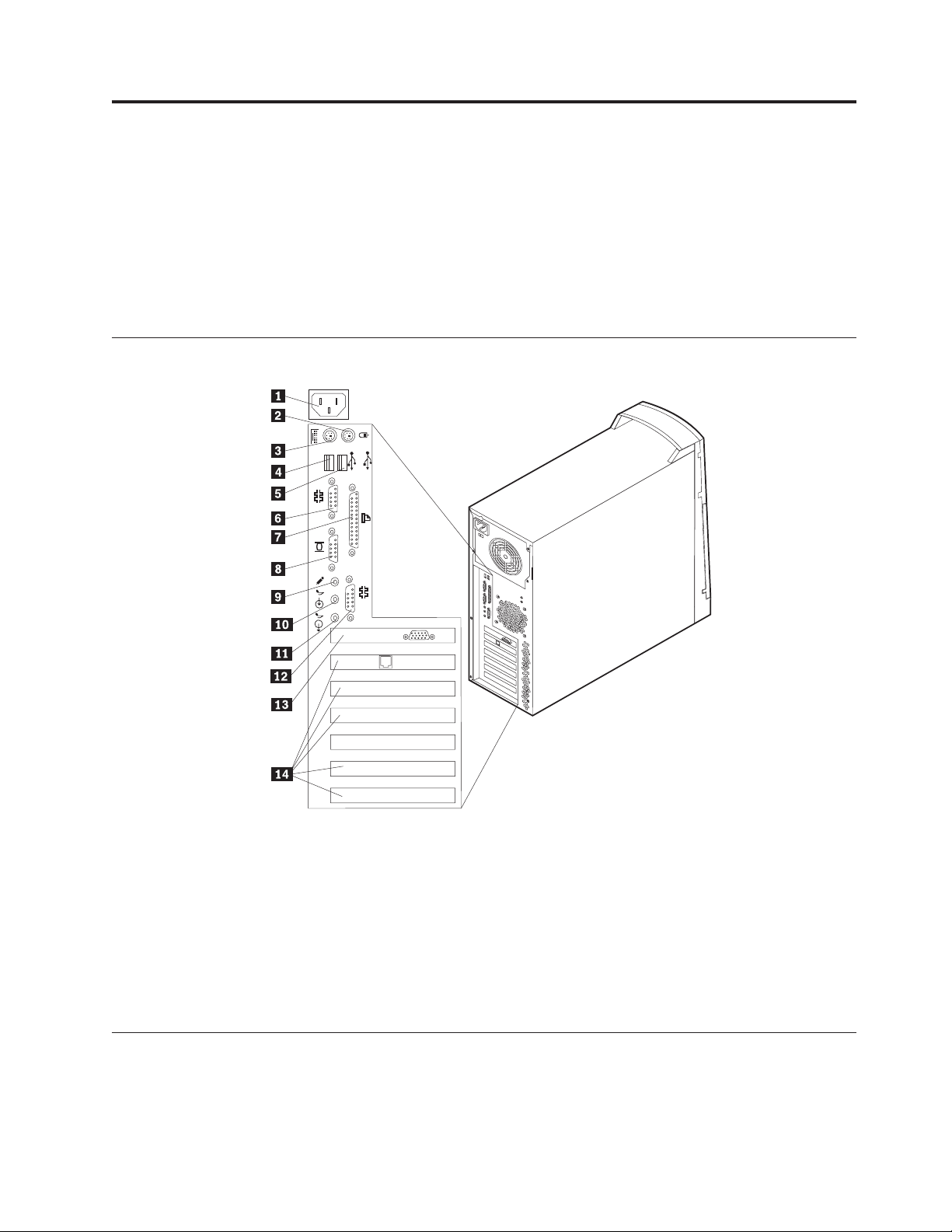
Input/Output connectors
2
1
1
2
Installing adapters . . . . . . . . . . . . 22
Adapter slots . . . . . . . . . . . . . 22
AGP adapter . . . . . . . . . . . . . 24
Audio adapter . . . . . . . . . . . . 25
ADSL modem . . . . . . . . . . . . 25
Home PNA network adapter . . . . . . . 25
Replacing the cover . . . . . . . . . . . . 26
1 Power connector 10 Audio in connector
2 Mouse connector 11 Audio out connector
3 Keyboard connector 12 Serial connector 2
4 USB connector 1 13 AGP slot
5 USB connector 2 14 PCI slot 1
6 Serial connector 1 14 PCI slot 2
7 Parallel connector 14 PCI slot 3
8 Monitor connector 14 PCI slot 4
9 Microphone connector 14 PCI slot 5
Removing the cover
1. Remove the two back thumb screws.
2. Disengage the keylock (if any) on the side of the computer.
© Copyright IBM Corp. 2000 15
Page 22
3. Push the side cover toward the rear, using the two embosses at the back of the
cover.
4. Remove the cover.
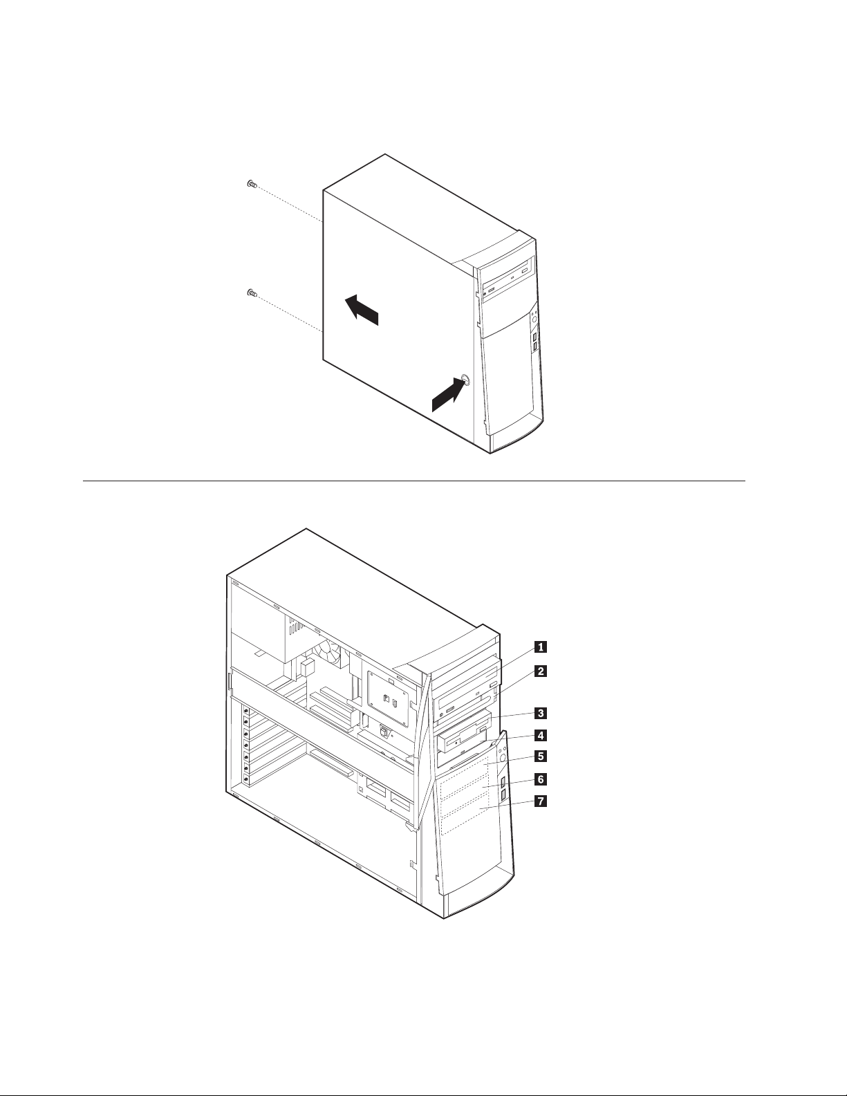
Internal drive removal and replacement
16 Hardware Maintenance Manual A40 Type 6840 A40P Type 6841 A40i Type 2271: IBM NetVista Computer
Page 23
1 Bay 1 - Max Height: 41.3 mm (1.6 in.)
CD-ROM drive (standard in some models)
5.25-inch hard disk drive
2 Bay 2 - Max Height: 41.3 mm (1.6 in.)
5.25-inch hard disk drive
3.5-inch hard disk drive (requires a mounting bracket)
CD-ROM drive
DVD-ROM drive
3 Bay 3 - Max Height: 25.4 mm (1.0 in.)
3.5-inch diskette drive
4 Bay 4 - Max Height: 25.4 mm (1.0 in.)
Hard disk drive
3.5-inch removable drive
5 Bay 5 - Max Height: 25.4 mm (1.0 in.)
Hard disk drive
6 Bay 6 - Max Height: 25.4 mm (1.0 in.)
Hard disk drive
7 Bay 7 - Max Height: 25.4 mm (1.0 in.)
Hard disk drive
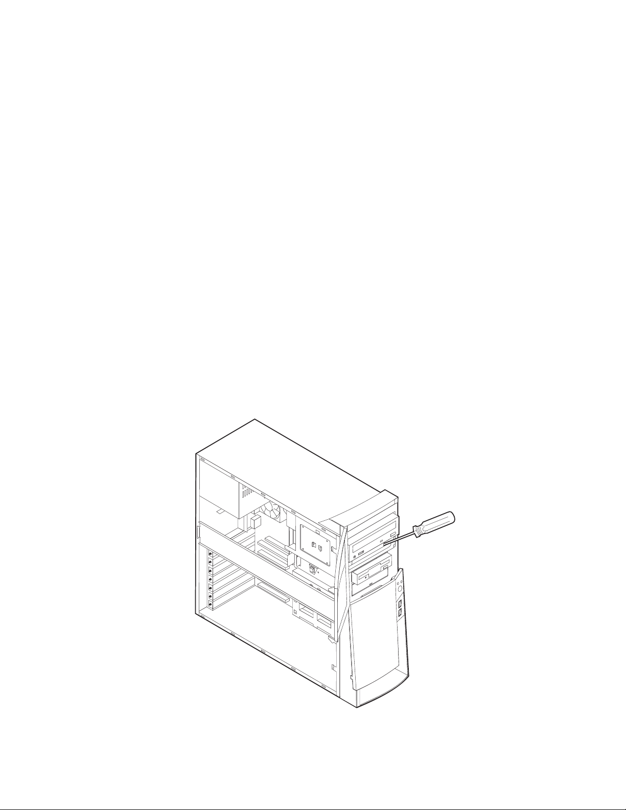
Installing internal drives in bays 1, 2, 3 and 4
1. Remove the cover (see “Removing the cover” on page 15).
2. If the drive you are installing is a removable-media drive, remove the bay
panel from the front bezel.
3. Insert a flat–bladed screwdriver into one of the slots on the static shield in the
drive bay into which you are installing the drive and gently pry the static
shield loose from the drive bay.
Chapter 4. Installing Options 17
Page 24
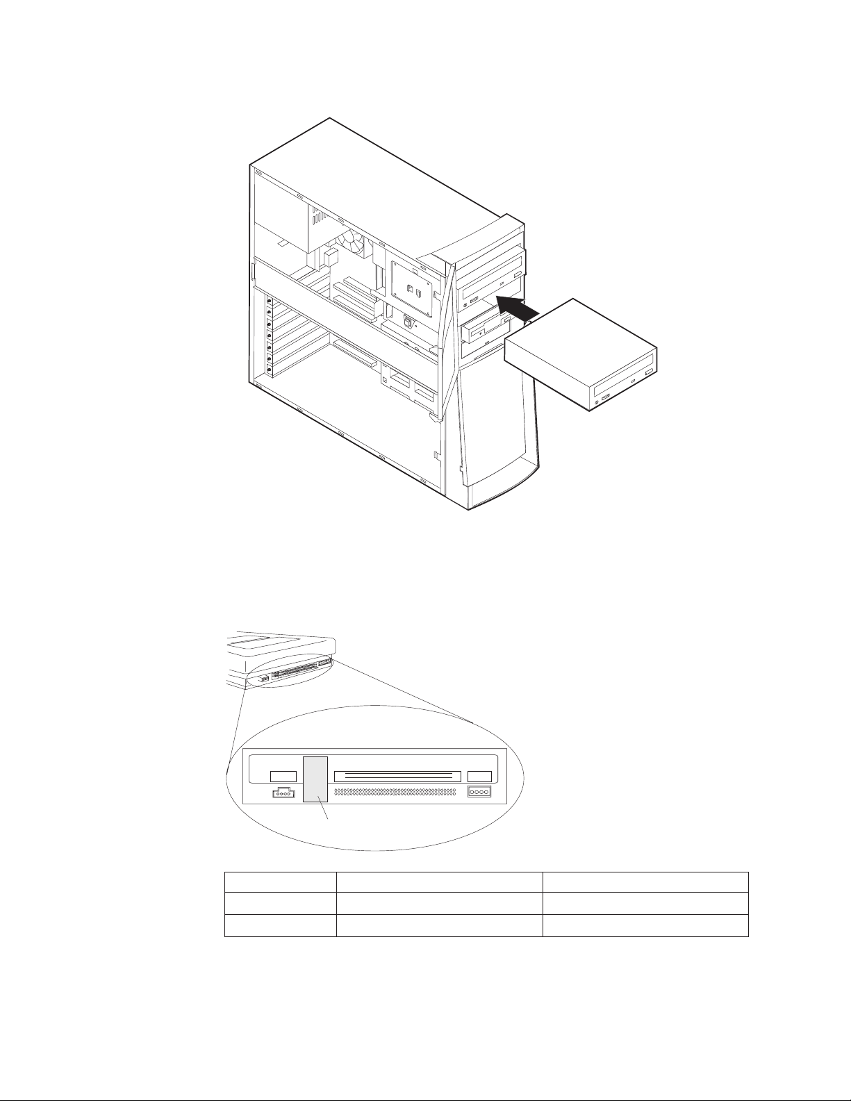
4. Install the drive into the bay. Align the screw holes and insert the two screws.
5. Connect the power and signal cables to the drive.
CD-ROM drive jumper settings
CD-ROM and PC/CD-ROM drives use jumpers or tabs to set the drives as primary
(master) or secondary (slave). Refer to the drive connector labels or the figures
below for the drive settings.
AUDIO
RGGL
See Jumper
Settings Below
CD-ROM Primary (Master) Secondary (Slave)
40X : : : :
48X : : : :
IDE INTERFACE
39
40
1
2
DC INPUT
5V GG 12V
Installing internal drives in bays 5, 6 and 7
1. Remove the cover (see “Removing the cover” on page 15).
18 Hardware Maintenance Manual A40 Type 6840 A40P Type 6841 A40i Type 2271: IBM NetVista Computer
Page 25
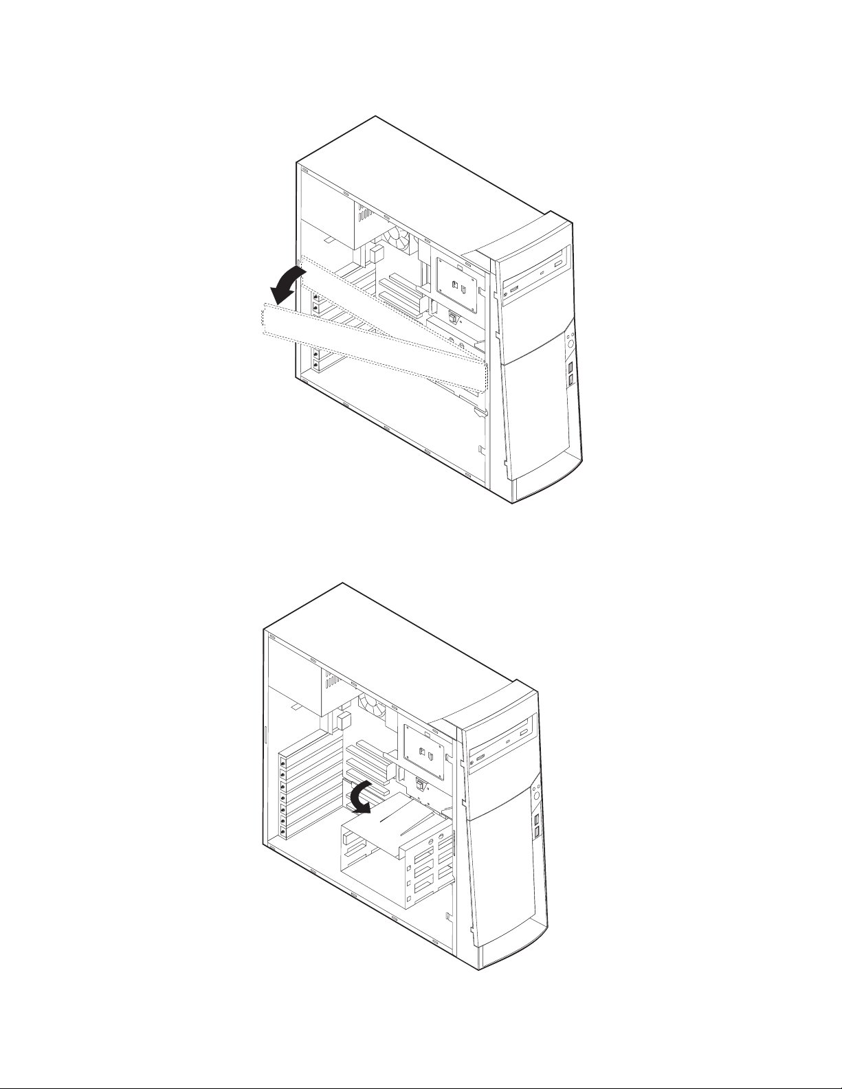
2. Remove the side support bar.
3. Remove the front EMC shield for the specific drive bay.
4. Pivot the lower drive bay cage outward from the computer, into the locked
position.
Chapter 4. Installing Options 19
Page 26
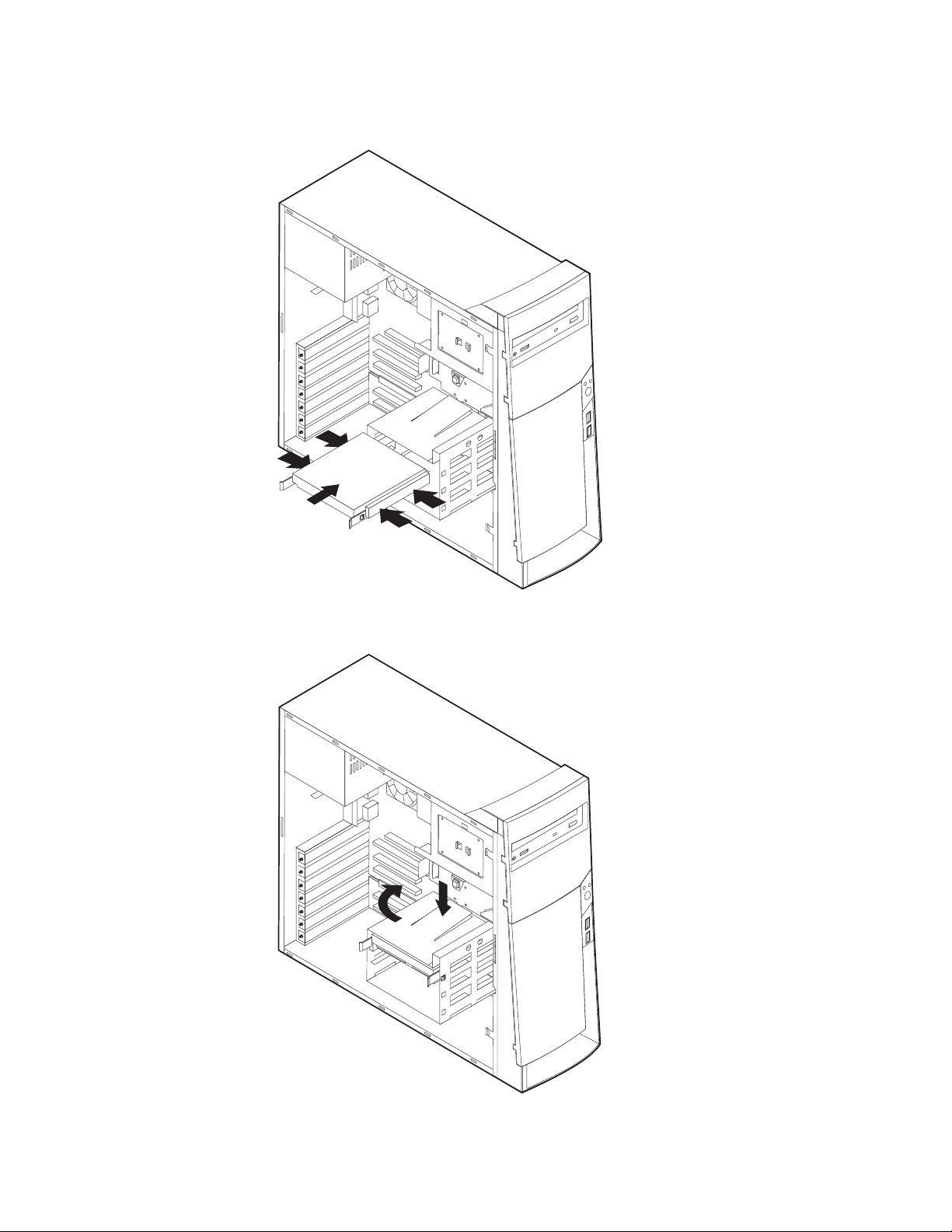
5. Mount DASD rails on the drive you wish to install and slide the drive along
the rail guides into the unoccupied drive bay.
6. Press the tab that holds the cage in the open position and swing the cage back
into operating position.
7. Connect the cables to the drive.
8. Connect the power and signal cables to the drive.
20 Hardware Maintenance Manual A40 Type 6840 A40P Type 6841 A40i Type 2271: IBM NetVista Computer
Page 27
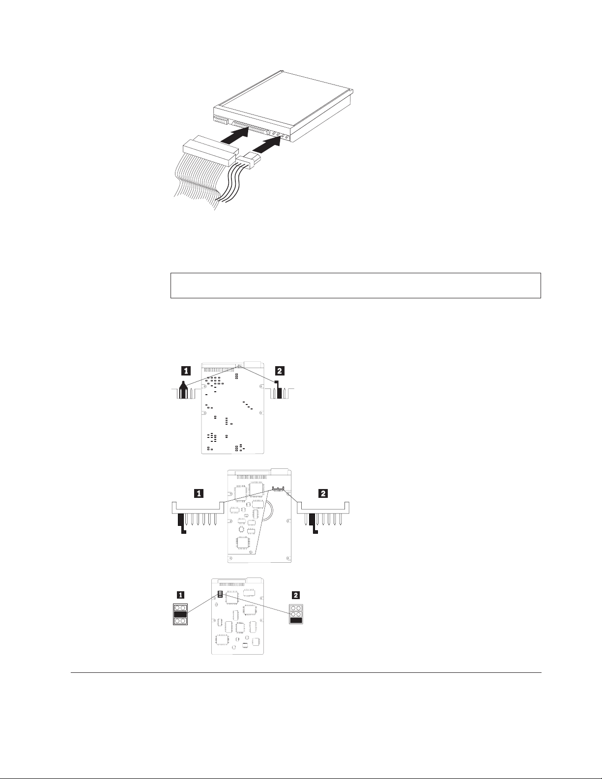
Hard disk drive jumper settings
IDE hard disk drives for the NetVista series computers use jumpers to set the
drives as primary (master) or secondary (slave).
Note: For drives not shown below, refer to the label on the hard disk drive for the hard
disk drive settings.
1Primary (Master) Hard Disk Drive
2Secondary (Slave) Hard Disk Drive
Installing a security U-bolt
To install a U-bolt, do the following:
1. Remove the cover.
Chapter 4. Installing Options 21
Page 28
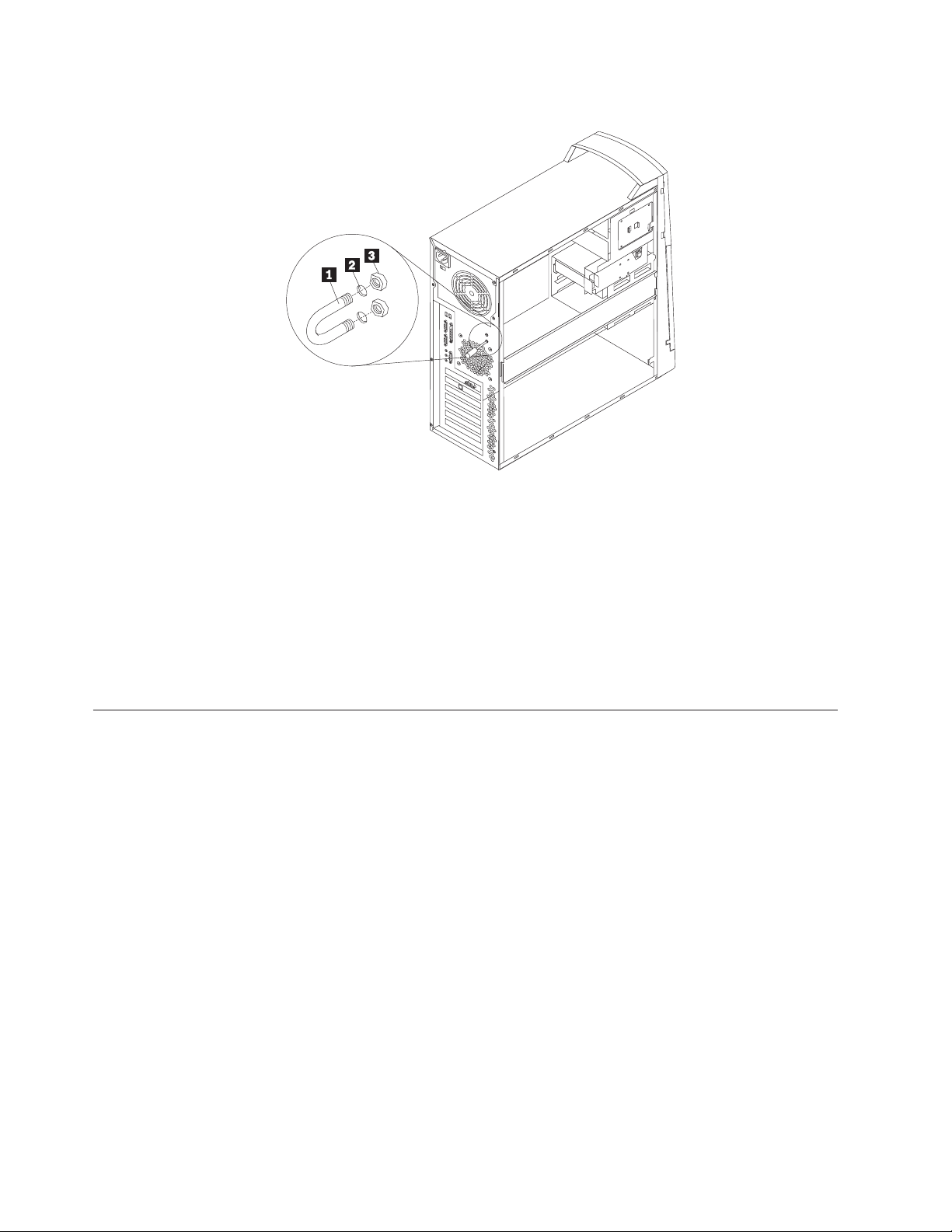
2. Remove the two metal knockouts.
1 U-bolt
2 Bolt holes
3 Nuts
3. Insert the U-bolt through the rear panel. Attach and tighten the nuts with an
appropriately sized or adjustable wrench.
4. Replace the computer cover. See “Replacing the cover” on page 26.
5. Thread the cable through the U-bolt and around an object that is not a part of
or permanently secured to the building structure or foundation, and from
which it cannot be removed; then fasten the cable ends together with a lock.
Installing adapters
Adapter slots
To install an adapter in a PCI or AGP expansion slot, do the following:
1. Remove the cover (see “Removing the cover” on page 15).
22 Hardware Maintenance Manual A40 Type 6840 A40P Type 6841 A40i Type 2271: IBM NetVista Computer
Page 29
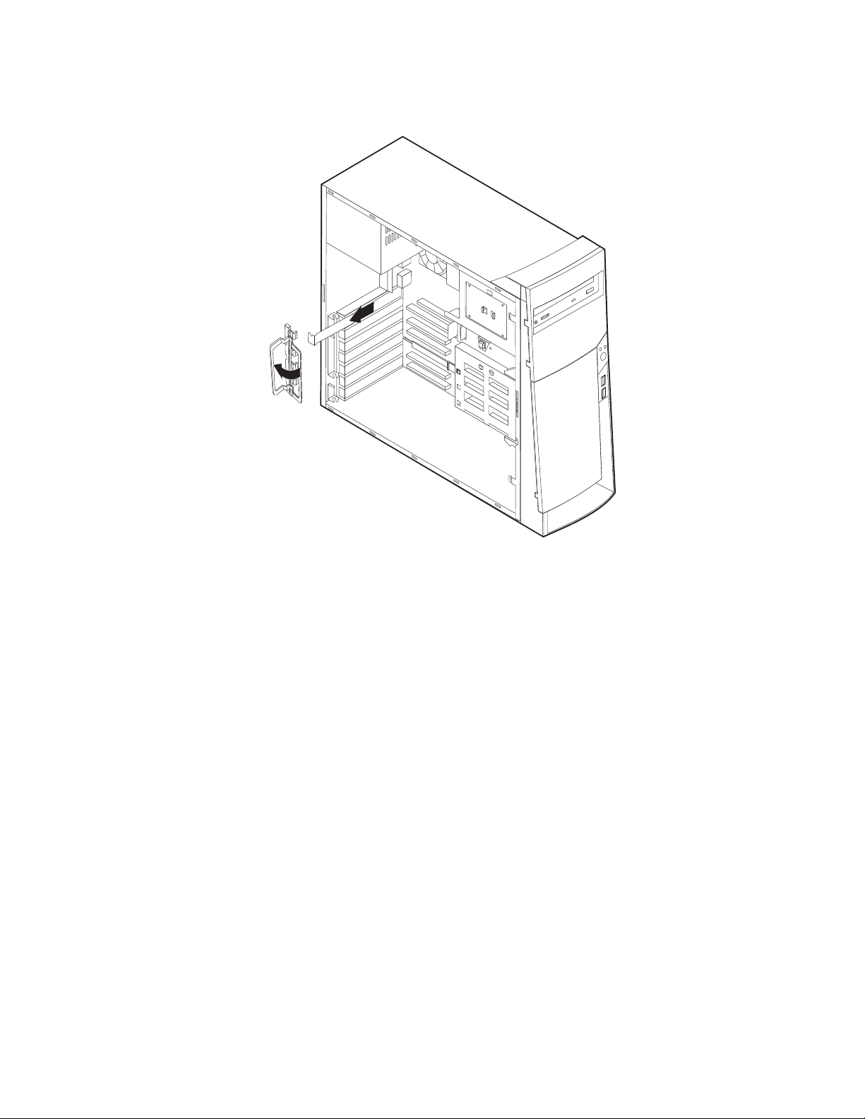
2. Remove the blue adapter card retainer and slot cover for the appropriate
expansion slot.
3. Remove the adapter from its static-protective package.
4. Install the adapter into the appropriate slot on the system board.
™
Note: If you are installing a Wake on LAN
supported network adapter, attach
the Wake on LAN cable that came with the adapter to the Wake on LAN
connector on the system board. If you also want to take advantage of the
Alert on LAN feature of the computer, you must install the network
adapter in PCI slot 1. For the location of PCI slot 1 and the Wake on
LAN connector, see the diagram of the system board on the inside of the
computer.
Chapter 4. Installing Options 23
Page 30
5. Install the adapter card retainer.
6. Replace the cover and connect the cables.
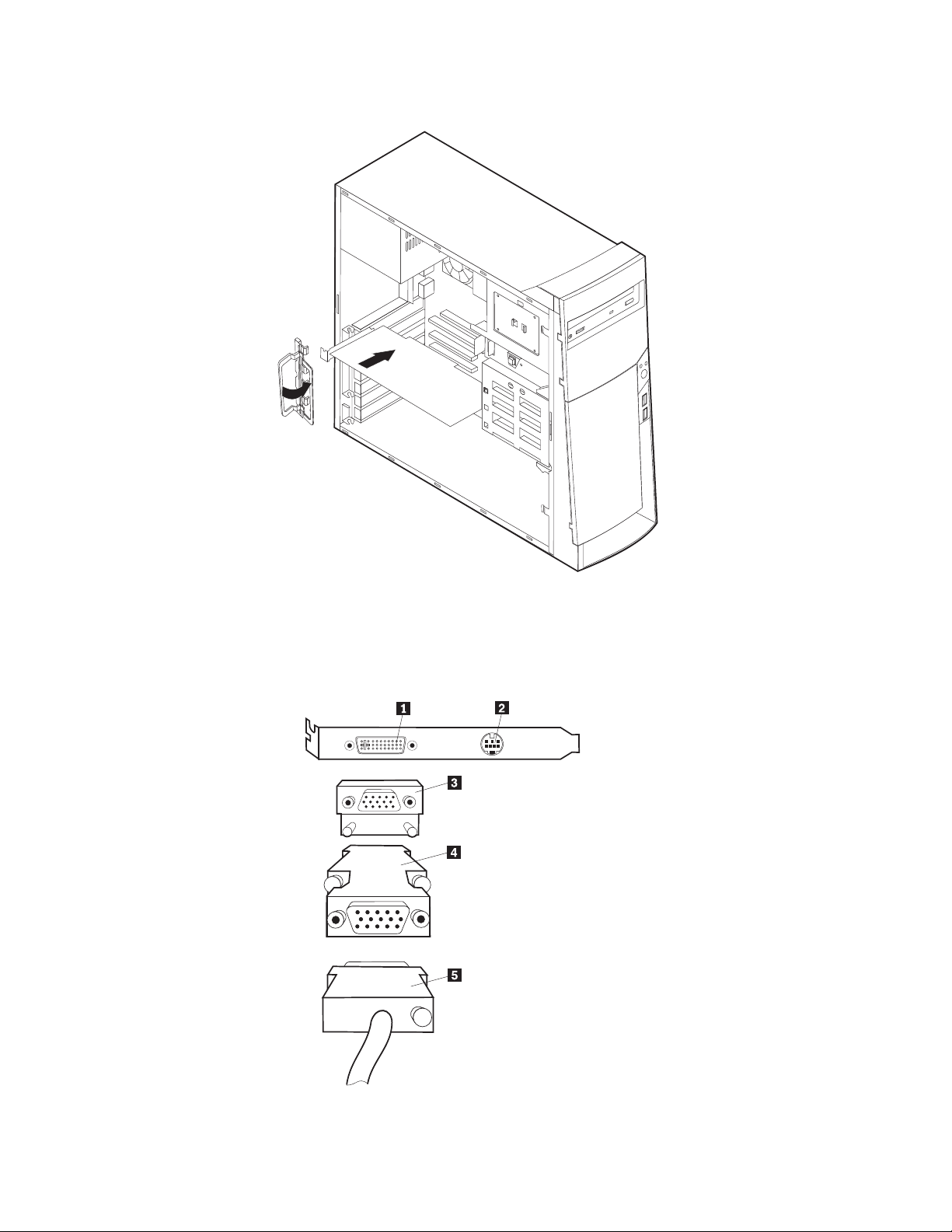
AGP adapter
Some models come with a high-performance AGP video adapter. In some AGP
adapters, the DVI connector is replaced by a regular VGA connector.
24 Hardware Maintenance Manual A40 Type 6840 A40P Type 6841 A40i Type 2271: IBM NetVista Computer
Page 31

Connector Description
1 Digital video interface
(DVI) connector
2 S-Video connector Used to attach a television set that has a S-Video connector.
3 SVGA monitor
converter
4 SVGA monitor
converter
Used to attach a digital monitor. This connector provides
the signals necessary to support the Display Power
Management Signaling (DPMS) standard.
The S-Video cable (required to connect the television set to
the adapter) is a separately purchased item.
Used to attach an analog SVGA monitor to the AGP DVI
connector. This SVGA converter is not used in this machine
type.
Used to attach an analog SVGA monitor to the AGP DVI
connector.
Audio adapter
1 MIDI/joystick connector
2 Audio line-out connector
3 Microphone connector
4 Audio line-in connector
Connector
ADSL modem
Depending on how the user’s home or office is wired, the ADSL modem uses
either wires 2 and 5 or wires 3 and 4 of the telephone-line wall connector. Refer to
the label on the back of the ADSL modem and set the switch on the back of the
ADSL modem to match the wiring scheme. If you do not know which wiring
scheme to use, contact the user’s ADSL service provider.
Home PNA network adapter
Some models have a Home Phoneline Network Alliance network adapter with an
integrated V.90 modem. In addition to its modem function, this adapter enables the
user to use the telephone wiring in the user’s home for peer-to-peer networking.
To use the Home PNA Network adapter, the Intel AnyPoint software must be
installed from the Software Selections CD. Each computer on the home PNA
network must have a PNA network adapter and the associated software installed.
For information about using the PNA network adapter or the AnyPoint software,
refer to the AnyPoint documentation (provided with models that come with PNA
network adapters only).
Each computer on a home PNA network must be connected directly to a
telephone-line wall connector. If the user has more computers than telephone-line
wall connectors in a room, he/she must use a telephone splitter at the wall
connector.
Chapter 4. Installing Options 25
Page 32

Replacing the cover
1. Position the cover on the chassis, aligning the tabs on the cover with the slots
on the chassis.
2. Slide the cover toward the front bezel of the computer until the cover is fully
closed.
3. Replace the two thumb screws and engage the keylock (if any).
26 Hardware Maintenance Manual A40 Type 6840 A40P Type 6841 A40i Type 2271: IBM NetVista Computer
Page 33

Chapter 5. FRU Replacements
Computer exploded view . . . . . . . . . . 28
A40/A40P/A40i system board layout . . . . . 29
System board locations . . . . . . . . . 29
System board jumper settings . . . . . . . 29
Clear CMOS/Flash Boot Block Recovery . . . 30
Processor Speed Settings . . . . . . . . 30
System board memory . . . . . . . . . . 30
Installing memory . . . . . . . . . . 30
PCI extender card removal . . . . . . . . . 31
Replacing a system board . . . . . . . . . 31
Replacing a processor . . . . . . . . . . . 32
Replacing the speaker . . . . . . . . . . . 32
Power supply . . . . . . . . . . . . . 33
20-pin main power supply connection . . . . 33
Power supply removal . . . . . . . . . . 34
© Copyright IBM Corp. 2000 27
Page 34

Computer exploded view
28 Hardware Maintenance Manual A40 Type 6840 A40P Type 6841 A40i Type 2271: IBM NetVista Computer
Page 35

A40/A40P/A40i system board layout
34
33
32
31
System board locations
1CPU fan connector 18PCI slot 5
2Microprocessor 19 PCI slot 4
3DIMM 0 20 PCI slot 3
4DIMM 1 21 PCI slot 2
5Power LED connector 22 PCI slot 1
6RFID connector 23 AGP slot
7Front USB connector 24 CD-ROM audio
8Secondary IDE connector 25 Speaker connector
9Diskette connector 26 Audio output
10Primary IDE connector 27 Audio input
11Power connector 28 Serial port 2
12CMOS clear/recovery jumper 29 Microphone input
13Fan connector 30 Monitor port
14Battery 31 Parallel port
15SCSI adapter LED connector 32 Serial port 1
16 Alert on LAN 33 USB connectors
17 Wake on LAN 34 Mouse and keyboard connectors
System board jumper settings
The following table contains the jumper setting information. (D) indicates the
default setting.
Chapter 5. FRU Replacements 29
Page 36

Clear CMOS/Flash Boot Block Recovery
Use the recovery jumper setting to Clear CMOS or to Flash Boot Block Recover.
Jumper Setting Description
CMOS Reset 2-3 CMOS Reset/Flash Recovery
Mode
1-2 (D) Normal Mode
Note: The A40/A40P/A40i CMOS clear/recovery jumper pins are numbered as follows:
v Pin 1 is the farthest from the battery.
v Pins 2 and 3 are below pin 1, as seen in the System Board layout.
Processor Speed Settings
Processor speed for type 2271/6840/6841 computers are fixed and are determined
by the processor. There are no settings required.
System board memory
Installing memory
When installing DIMMs, the following rules apply:
v Fill each system memory connector sequentially, starting at DIMM 0.
v Use 3.3 V, 133 MHz, unbuffered, SDRAM non-parity DIMMs.
v Use only 64, 128, or 256 MB DIMMs in any combination.
To install a memory module, do the following:
1. Remove the AGP adapter.
2. Locate the DIMM connectors.
3. If the retaining clips are not already open, open them.
30 Hardware Maintenance Manual A40 Type 6840 A40P Type 6841 A40i Type 2271: IBM NetVista Computer
Page 37

4. Install the DIMM straight down into the connector until the retaining clips
close. Make sure the notches in the DIMM align with the tabs on the connector.
PCI extender card removal
1. Remove the cover (see “Removing the cover” on page 15).
2. Remove the machine chassis foot that is in front of the extender card.
3. Remove the 2 screws that hold the PCI extender card in place.
4. Pull the card down (not out) firmly on both sides until it detaches from the
system board.
Notches
Replacing a system board
Important:
Before replacing a system board, back up Asset information by using the “Asset EEPROM
backup” on page 12.
Notes:
1. The BIOS and Vital Product Data (VPD) for the computer you are servicing must be
installed on the new system board (FRU) after it is installed in the computer. To do
this, you must run the Flash Update program using the Flash Update diskette. See
“BIOS levels” on page 87, “Vital product data” on page 86, and “Flash (BIOS/VPD)
update procedure” on page 88.
2. Always ensure the latest level of BIOS is installed on the computer. A down level BIOS
may cause false errors and unnecessary replacement of the system board.
3. The processor is a separate FRU from the system board and is not included with the
system board FRU.
4. If the new system board does not correct the problem, reinstall the options on the old
system board, reinstall the old system board, then replace the processor.
To replace the system board, do the following:
1. Remove the cover (see “Removing the cover” on page 15).
2. Remove the video card.
3. Remove the machine chassis foot that is in front of the PCI extender card.
4. Remove the extender card (see “PCI extender card removal” on page 31).
5. Remove the 7 screws that attach the system board to the chassis.
Chapter 5. FRU Replacements 31
Page 38

6. Remove the board from the chassis.
7. Remove the processor from the old system board and install it on the new
system board.
8. Remove any of the following installed options on the old system board, and
install them on the new system board.
v Memory modules
9. Ensure that the new system board jumper settings match the old system board
jumper settings.
Replacing a processor
Make sure the processor is fully seated in its socket and that the goal post latches
are engaged.
Important:
1. Make sure the fansink and air baffle (if any) are installed to prevent processor
overheating.
2. If the processor is not installed correctly, the system board and the processor can be
damaged.
Replacing the speaker
1. Remove the cover (see “Removing the cover” on page 15).
32 Hardware Maintenance Manual A40 Type 6840 A40P Type 6841 A40i Type 2271: IBM NetVista Computer
Page 39

2. The speaker is secured by one tab on either side and two at the bottom. Firmly
push the speaker up from the bottom until it comes out from the tabs.
Power supply
20-pin main power supply connection
If the power-on indicator is not on, the power supply fan is not running, or the
computer will not power-off, use the following procedures.
Check/Verify FRU/Action
Check the following for proper installation.
v Power Cord
v On/Off Switch connector
v On/Off Switch Power Supply connector
v System Board Power Supply connectors
v Microprocessor(s) connection
Check the power-on switch for continuity. Power Cord
Check the power-on switch for continuity. Power-on Switch
Reseat
See “A40/A40P/A40i system board layout” on page 29 for connector locations.
Attention:
These voltages must be checked with the power supply cables connected to the system
board
Chapter 5. FRU Replacements 33
Page 40

Pin Signal Function
1 3.3 V +3.3 V dc
2 3.3 V +3.3 V dc
3 COM Ground
4 5 V +5 V dc
5 COM Ground
6 5 V +5 V dc
7 COM Ground
8 POK Power Good
9 5VSB Standby Voltage
10 12 V +12 V dc
11 3.3 V +3.3 V dc
12 -12 V -12 V dc
13 COM Ground
14 PS-ON DC Remote Enable
15 COM Ground
16 COM Ground
17 COM Ground
18 No voltage Not used
19 5 V +5 V dc
20 5 V +5 V dc
If the voltages are not correct, and the power cord is good, replace the power
supply.
Power supply removal
1. Remove the power cable.
2. Remove the cover (see “Removing the cover” on page 15).
3. Remove the four screws that secure the power supply to the back of the
chassis.
34 Hardware Maintenance Manual A40 Type 6840 A40P Type 6841 A40i Type 2271: IBM NetVista Computer
Page 41

4. Remove the power supply.
Chapter 5. FRU Replacements 35
Page 42

36 Hardware Maintenance Manual A40 Type 6840 A40P Type 6841 A40i Type 2271: IBM NetVista Computer
Page 43

Chapter 6. Symptom-to-FRU Index
SIMM/DIMM/RIMM memory errors . . . . . . 37
Hard disk drive boot error . . . . . . . . . 38
Diagnostic error codes . . . . . . . . . . . 39
Beep symptoms . . . . . . . . . . . . . 57
The Symptom-to-FRU index lists error symptoms and possible causes. The most
likely cause is listed first. Always begin with Chapter 1, “General Checkout,” on
page 1. This index can also be used to help you decide which FRUs to have
available when servicing a computer. If you are unable to correct the problem
using this index, go to “Undetermined problems” on page 75.
Notes:
v If you have both an error message and an incorrect audio response, diagnose the error
message first.
v If you cannot run the diagnostic tests or you get a diagnostic error code when running a
test, but did receive a POST error message, diagnose the POST error message first.
v If you did not receive any error message, look for a description of your error symptoms
in the first part of this index.
v Check all power supply voltages before you replace the system board (see “Power
supply” on page 33).
v Check the hard disk drive jumper settings before you replace a hard disk drive (see
“Hard disk drive jumper settings” on page 21).
Important:
No-beep symptoms . . . . . . . . . . . . 58
POST error codes . . . . . . . . . . . . 59
Miscellaneous error messages . . . . . . . . 73
Undetermined problems . . . . . . . . . . 75
Some errors are indicated with a series of beep codes (see “Beep symptoms” on page 57).
Type 2271/6840/6841 computers default to come up quiet (no beep and no memory count
and checkpoint code display) when no errors are detected by POST. To enable beep and
memory count and checkpoint code display when a successful POST occurs, do the
following:
1. Select Start Options in the Configuration/Setup Utility program (see “Setup Utility
program” on page 7).
2. Set Power-On Self-Test to Enhanced.
The processor is a separate FRU from the system board; the processor is not included with
the system board FRU.
SIMM/DIMM/RIMM memory errors
The following SIMM/DIMM/RIMM error messages are issued by the diagnostic
programs.
Error FRU/Action
2xx-1y
A memory error was detected in SIMM
socket Y.
Replace the SIMM in the socket identified by
the last digit of the error code.
Re-run the test.
If the same error code occurs again, replace
the system board.
© Copyright IBM Corp. 2000 37
Page 44

Error FRU/Action
2xx-2y
A memory error was detected in
DIMM/RIMM socket Y
Corrupt BIOS
Replace the DIMM/RIMM in the socket
identified by the last digit of the error code.
Re-run the test.
If the same error code occurs again, replace
the system board or where memory is on
the processor card, replace the processor
card.
Reflash the BIOS.
Information in BIOS is not as expected.
Not able to find expected DMI information
from BIOS.
Memory controller chipset vendor ID does
not match expected value.
Test aborted by user Restart test.
Note: Y is the SIMM/DIMM/RIMM socket number. Use the System Board Layout
section in the latest Hardware Maintenance Manual (HMM) to reference the
memory sockets.
Hard disk drive boot error
A hard disk drive boot error (error codes 1962 and I999030X) can have the
following causes.
Error FRU/Action
The start-up drive is not in the boot
sequence in configuration.
No operating system installed on the boot
drive.
The boot sector on the start-up drive is
corrupted.
The drive is defective. Replace the hard disk drive.
Perform boot block recovery.
Replace the system board.
Check the configuration and ensure the
start-up drive is in the boot sequence.
Install an operating system on the boot
drive.
The drive must be formatted, do the
following:
1. Attempt to access and recover (back-up)
the failing hard disk drive.
2. Using the operating systems programs,
format the hard disk drive.
3. Go to “Preparing the hard disk drive for
use” on page 13.
38 Hardware Maintenance Manual A40 Type 6840 A40P Type 6841 A40i Type 2271: IBM NetVista Computer
Page 45

Diagnostic error codes
Refer to the following diagnostic error codes when using the diagnostic tests. See
″Diagnostics″ on page 7 for the specific type for information about the diagnostic
programs.
In the following index, X can represent any number.
Diagnostic Error Code FRU/Action
000-000-XXX
BIOS Test Passed
000-002-XXX
BIOS Timeout
000-024-XXX
BIOS Addressing test failure
000-025-XXX
BIOS Checksum Value error
000-026-XXX
FLASH data error
000-027-XXX
BIOS Configuration/Setup error
000-034-XXX
BIOS Buffer Allocation failure
000-035-XXX
BIOS Reset Condition detected
000-036-XXX
BIOS Register error
000-038-XXX
BIOS Extension failure
000-039-XXX
BIOS DMI data error
000-195-XXX
BIOS Test aborted by user
000-196-XXX
BIOS test halt, error threshold exceeded
1. No action
1. Flash the system
2. System board
1. Flash the system
2. System board
1. Flash the system
2. Boot block
3. System board
1. Flash the system
2. Boot block
3. System board
1. Run Setup
2. Flash the system
3. Boot block
4. System board
1. Reboot the system
2. Flash the system
3. Run memory test
4. System board
1. Flash the system
2. System board
1. Flash the system
2. Boot block
3. System board
1. Flash the system
2. Adapter card
3. System board
1. Flash the system
2. System board
1. Information
2. Re-start the test, if necessary
1. Press F3 to review the log file
2. Re-start the test to reset the log file
Chapter 6. Symptom-to-FRU Index 39
Page 46

Diagnostic Error Code FRU/Action
000-197-XXX
BIOS test warning
000-198-XXX
BIOS test aborted
000-199-XXX
BIOS test failed, cause unknown
000-250-XXX
BIOS APM failure
000-270-XXX
BIOS ACPI failure
001-000-XXX
System Test Passed
001-00X-XXX
System Error
001-01X-XXX
System Error
001-024-XXX
System Addressing test failure
001-025-XXX
System Checksum Value error
001-026-XXX
System FLASH data error
001-027-XXX
System Configuration/Setup error
001-032-XXX
System Device Controller failure
001-034-XXX
System Device Buffer Allocation failure
001-035-XXX
System Device Reset condition detected
001-036-XXX
System Register error
1. Make sure the component that is called
out is connected and/or enabled
2. Re-run test
3. Component that is called out in warning
statement
4. Component under test
1. If a component is called out, make sure
it is connected and/or enabled
2. Flash the system and re-test
3. Go to the ″Undetermined problems″
section
1. Go to the ″Undetermined problems″
section
2. Flash the system and re-test
3. Replace component under function test
1. Flash the system
2. System board
1. Flash the system
2. System board
1. No action
1. System board
1. System board
1. System board
1. Flash the system
2. System board
1. Flash the system
2. System board
1. Run Setup
2. Flash the system
3. System board
1. System board
1. Reboot the system
2. Flash the system
3. Run memory test
4. System board
1. System board
1. System board
40 Hardware Maintenance Manual A40 Type 6840 A40P Type 6841 A40i Type 2271: IBM NetVista Computer
Page 47

Diagnostic Error Code FRU/Action
001-038-XXX
System Extension failure
001-039-XXX
System DMI data structure error
001-040-XXX
System IRQ failure
001-041-XXX
System DMA failure
001-195-XXX
System Test aborted by user
001-196-XXX
System test halt, error threshold exceeded
001-197-XXX
System test warning
1. Adapter card
2. System board
1. Flash the system
2. System board
1. Power-off/on system and re-test
2. System board
1. Power-off/on system and re-test
2. System board
1. Information
2. Re-start the test, if necessary
1. Press F3 to review the log file
2. Re-start the test to reset the log file
1. Make sure the component that is called
out is connected and/or enabled
2. Re-run test
3. Component that is called out in warning
statement
001-198-XXX
System test aborted
4. Component under test
1. If a component is called out, make sure
it is connected and/or enabled
2. Flash the system and re-test
3. Go to the ″Undetermined problems″
section
001-199-XXX
System test failed, cause unknown
1. Go to the ″Undetermined problems″
section
2. Flash the system and re-test
001-250-XXX
System ECC error
001-254-XXX
001-255-XXX
3. Replace component under function test
1. System board
1. System board
001-256-XXX
001-257-XXX
System DMA error
001-260-XXX
001-264-XXX
System IRQ error
001-268-XXX
System IRQ1 failure
001-269-XXX
System IRQ2 failure
001-270-XXX
System IRQ3 failure
1. System board
1. Device on IRQ1
2. System board
1. Device on IRQ2
2. System board
1. Device on IRQ3
2. System board
Chapter 6. Symptom-to-FRU Index 41
Page 48

Diagnostic Error Code FRU/Action
001-271-XXX
System IRQ4 failure
001-272-XXX
System IRQ5 failure
001-273-XXX
System IRQ6
(diskette drive) failure
001-274-XXX
System IRQ7 failure
001-275-XXX
System IRQ8 failure
001-276-XXX
System IRQ9 failure
001-277-XXX
System IRQ10 failure
001-278-XXX
System IRQ11 failure
001-279-XXX
System IRQ12 failure
001-280-XXX
System IRQ13 failure
001-281-XXX
System IRQ14
(hard disk drive) failure
001-282-XXX
System IRQ15 failure
001-286-XXX
001-287-XXX
001-288-XXX
System Timer failure
001-292-XXX
System CMOS
RAM error
001-293-XXX
System CMOS Battery
001-298-XXX
System RTC date/time update failure
001-299-XXX
System RTC periodic interrupt failure
001-300-XXX
System RTC Alarm failure
1. Device on IRQ4
2. System board
1. Device on IRQ5
2. System board
1. Diskette Cable
2. Diskette drive
3. System board
1. Device on IRQ7
2. System board
1. Device on IRQ8
2. System board
1. Device on IRQ9
2. System board
1. Device on IRQ10
2. System board
1. Device on IRQ11
2. System board
1. Device on IRQ12
2. System board
1. Device on IRQ13
2. System board
1. Hard disk drive cable
2. Hard disk drive
3. System board
1. Device on IRQ15
2. System board
1. System board
1. Run Setup and re-test
2. System board
1. Battery
2. System board
1. Flash the system
2. System board
1. System board
1. System board
42 Hardware Maintenance Manual A40 Type 6840 A40P Type 6841 A40i Type 2271: IBM NetVista Computer
Page 49

Diagnostic Error Code FRU/Action
001-301-XXX
System RTC Century byte error
005-000-XXX
Video Test Passed
005-00X-XXX
Video error
005-010-XXX
005-011-XXX
005-012-XXX
1. Flash the system
2. System board
1. No action
1. Video card, if installed
2. System board
1. Video card, if installed
2. System board
005-013-XXX
Video Signal failure
005-016-XXX
Video Simple Pattern
test failure
005-024-XXX
Video Addressing test failure
005-025-XXX
Video Checksum Value error
005-027-XXX
Video Configuration/Setup error
1. Video Ram
2. Video card, if installed
3. System board
1. Video card, if installed
2. System board
1. Video card, if installed
2. System board
1. Run Setup
2. Video drivers update
3. Video card, if installed
005-031-XXX
Video Device Cable failure
4. System board
1. Video cable
2. Monitor
3. Video card, if installed
005-032-XXX
Video Device Controller failure
005-036-XXX
Video Register error
005-038-XXX
System BIOS extension failure
005-040-XXX
Video IRQ failure
005-195-XXX
Video Test aborted by user
005-196-XXX
Video test halt, error threshold exceeded
4. System board
1. Video card, if installed
2. System board
1. Video card, if installed
2. System board
1. Video card, if installed
2. System board
1. Video card, if installed
2. System board
1. Information
2. Re-start the test, if necessary
1. Press F3 to review the log file
2. Re-start the test to reset the log file
Chapter 6. Symptom-to-FRU Index 43
Page 50

Diagnostic Error Code FRU/Action
005-197-XXX
Video test warning
005-198-XXX
Video test aborted
005-199-XXX
Video test failed, cause unknown
005-2XX-XXX
005-3XX-XXX
Video subsystem error
006-000-XXX
Diskette interface Test Passed
006-0XX-XXX
Diskette interface error
006-195-XXX
Diskette interface Test aborted by user
006-196-XXX
Diskette interface test halt, error threshold
exceeded
006-197-XXX
Diskette interface test warning
006-198-XXX
Diskette interface test aborted
006-199-XXX
Diskette interface test failed, cause unknown
006-25X-XXX
Diskette interface Error
1. Make sure the component that is called
out is connected and/or enabled
2. Re-run test
3. Component that is called out in warning
statement
4. Component under test
1. If a component is called out, make sure
it is connected and/or enabled
2. Flash the system and re-test
3. Go to the ″Undetermined problems″
section
1. Go to the ″Undetermined problems″
section
2. Flash the system and re-test
3. Replace component under function test
1. Video card, if installed
2. System board
1. No action
1. Diskette drive Cable
2. Diskette drive
3. System board
1. Information
2. Re-start the test, if necessary
1. Press F3 to review the log file
2. Re-start the test to reset the log file
1. If a component is called out, make sure
it is connected and/or enabled
2. Re-run test
3. Component that is called out in warning
statement
4. Component under test
1. If a component is called out, make sure
it is connected and/or enabled
2. Flash the system and re-test
3. Go to the ″Undetermined problems″
section
1. Go to the ″Undetermined problems″
section
2. Flash the system and re-test
3. Replace component under function test
1. Diskette drive cable
2. Diskette drive
3. System board
44 Hardware Maintenance Manual A40 Type 6840 A40P Type 6841 A40i Type 2271: IBM NetVista Computer
Page 51

Diagnostic Error Code FRU/Action
011-000-XXX
Serial port Interface Test Passed
011-001-XXX
Serial port Presence
1. No action
1. Remove external serial device, if
present
2. Run setup, enable port
011-002-XXX
011-003-XXX
Serial port Timeout/Parity error
011-013-XXX
011-014-XXX
3. System board
1. System board
1. System board
Serial port Control Signal/Loopback test
failure
011-015-XXX
Serial port External Loopback failure
011-027-XXX
Serial port Configuration/Setup error
011-03X-XXX
011-04X-XXX
Serial port failure
011-195-XXX
Serial port Test aborted by user
011-196-XXX
Serial port test halt, error threshold exceeded
011-197-XXX
Serial port test warning
1. Wrap plug
2. System board
1. Run Setup, enable port
2. Flash the system
3. System board
1. System board
1. Information
2. Re-start the test, if necessary
1. Press F3 to review the log file
2. Re-start the test to reset the log file
1. Make sure the component that is called
out is connected and/or enabled
2. Re-run test
3. Component that is called out in warning
statement
011-198-XXX
Serial port test aborted
4. Component under test
1. If a component is called out, make sure
it is connected and/or enabled
2. Flash the system and re-test
3. Go to the ″Undetermined problems″
section
011-199-XXX
Serial port test failed, cause unknown
1. Go to the ″Undetermined problems″
section
2. Flash the system and re-test
011-2XX-XXX
Serial port signal failure
014-000-XXX
Parallel port Interface Test Passed
3. Replace component under function test
1. External serial device
2. System board
1. No action
Chapter 6. Symptom-to-FRU Index 45
Page 52

Diagnostic Error Code FRU/Action
014-001-XXX
Parallel port Presence
014-002-XXX
014-003-XXX
Parallel port Timeout/Parity error
014-013-XXX
014-014-XXX
Parallel port Control Signal/Loopback test
failure
014-015-XXX
Parallel port External Loopback failure
014-027-XXX
Parallel port Configuration/Setup error
014-03X-XXX
014-04X-XXX
Parallel port failure
014-195-XXX
Parallel port Test aborted by user
014-196-XXX
Parallel port test halt, error threshold
exceeded
014-197-XXX
Parallel port test warning
014-198-XXX
Parallel port test aborted
014-199-XXX
Parallel port test failed, cause unknown
014-2XX-XXX
014-3XX-XXX
Parallel port failure
015-000-XXX
USB port Interface Test Passed
015-001-XXX
USB port Presence
1. Remove external parallel device, if
present
2. Run setup, enable port
3. System board
1. System board
1. System board
1. Wrap plug
2. System board
1. Run Setup, enable port
2. Flash the system
3. System board
1. System board
1. Information
2. Re-start the test, if necessary
1. Press F3 to review the log file
2. Re-start the test to reset the log file
1. Make sure the component that is called
out is connected and/or enabled
2. Re-run test
3. Component that is called out in warning
statement
4. Component under test
1. If a component is called out, make sure
it is connected and/or enabled
2. Flash the system and re-test
3. Go to the ″Undetermined problems″
section
1. Go to the ″Undetermined problems″
section
2. Flash the system and re-test
3. Replace component under function test
1. External parallel device
2. System board
1. No action
1. Remove USB device(s) and re-test
2. System board
46 Hardware Maintenance Manual A40 Type 6840 A40P Type 6841 A40i Type 2271: IBM NetVista Computer
Page 53

Diagnostic Error Code FRU/Action
015-002-XXX
USB port Timeout
015-015-XXX
USB port External Loopback failure
015-027-XXX
USB port Configuration/Setup error
015-032-XXX
USB port Device Controller failure
015-034-XXX
USB port buffer
allocation failure
1. Remove USB device(s) and re-test
2. System board
1. Remove USB device(s) and re-test
2. System board
1. Flash the system
2. System board
1. System board
1. Reboot the system
2. Flash the system
3. Run memory test
015-035-XXX
USB port Reset condition detected
015-036-XXX
USB port Register error
015-040-XXX
USB port IRQ failure
015-195-XXX
USB port Test aborted by user
015-196-XXX
USB port test halt, error threshold exceeded
015-197-XXX
USB port test warning
4. System board
1. Remove USB device(s) and re-test
2. System board
1. System board
1. Run setup and check for conflicts
2. Flash the system
3. System board
1. Information
2. Re-start the test, if necessary
1. Press F3 to review the log file
2. Re-start the test to reset the log file
1. Make sure the component that is called
out is connected and/or enabled
2. Re-run test
3. Component that is called out in warning
statement
015-198-XXX
USB port test aborted
4. Component under test
1. If a component is called out, make sure
it is connected and/or enabled
2. Flash the system and re-test
3. Go to the ″Undetermined problems″
section
015-199-XXX
USB port test failed, cause unknown
1. Go to the ″Undetermined problems″
section
2. Flash the system and re-test
018-000-XXX
PCI Card Test Passed
018-0XX-XXX
PCI Card Failure
3. Replace component under function test
1. No action
1. Riser card, if installed
2. System board
Chapter 6. Symptom-to-FRU Index 47
Page 54

Diagnostic Error Code FRU/Action
018-195-XXX
PCI Card Test aborted by user
018-196-XXX
PCI Card test halt, error threshold exceeded
018-197-XXX
PCI Card test warning
018-198-XXX
PCI Card test aborted
018-199-XXX
PCI Card test failed, cause unknown
018-250-XXX
PCI Card Services error
020-000-XXX
PCI Interface Test Passed
020-0XX-XXX
PCI Interface error
020-195-XXX
PCI Test aborted by user
020-196-XXX
PCI test halt, error threshold exceeded
020-197-XXX
PCI test warning
020-198-XXX
PCI test aborted
1. PCI card
2. Information
3. Re-start the test, if necessary
1. Press F3 to review the log file
2. Re-start the test to reset the log file
1. Make sure the component that is called
out is connected and/or enabled
2. Re-run test
3. Component that is called out in warning
statement
4. Component under test
1. Make sure the component that is called
out is connected and/or enabled
2. Flash the system and re-test
3. Go to the ″Undetermined problems″
section
1. Go to the ″Undetermined problems″
section
2. Flash the system and re-test
3. Replace component under function test
1. PCI card
2. Riser card, if installed
3. System board
1. No action
1. PCI card
2. Riser card, if installed
3. System board
1. Information
2. Re-start the test, if necessary
1. Press F3 to review the log file
2. Re-start the test to reset the log file
1. Make sure the component that is called
out is connected and/or enabled
2. Re-run test
3. Component that is called out in warning
statement
4. Component under test
1. If a component is called out, make sure
it is connected and/or enabled
2. Flash the system and re-test
3. Go to the ″Undetermined problems″
section
48 Hardware Maintenance Manual A40 Type 6840 A40P Type 6841 A40i Type 2271: IBM NetVista Computer
Page 55

Diagnostic Error Code FRU/Action
020-199-XXX
PCI test failed, cause unknown
1. Go to the ″Undetermined problems″
section
2. Flash the system and re-test
020-262-XXX
PCI system error
3. Replace component under function test
1. PCI card
2. Riser card, if installed
3. System board
025-000-XXX
IDE interface Test Passed
025-00X-XXX
025-01X-XXX
IDE interface failure
1. No action
1. IDE signal cable
2. Check power supply
3. IDE device
025-027-XXX
IDE interface Configuration/Setup error
4. System board
1. IDE signal cable
2. Flash the system
3. IDE device
025-02X-XXX
025-03X-XXX
025-04X-XXX
IDE Interface failure
025-195-XXX
IDE interface Test aborted by user
025-196-XXX
IDE interface test halt, error threshold
exceeded
025-197-XXX
IDE interface test warning
4. System board
1. IDE signal cable
2. Check power supply
3. IDE device
4. System board
1. Information
2. Re-start the test, if necessary
1. Press F3 to review the log file
2. Re-start the test to reset the log file
1. Make sure the component that is called
out is connected and/or enabled
2. Re-run test
3. Component that is called out in warning
statement
025-198-XXX
IDE interface test aborted
4. Component under test
1. If a component is called out, make sure
it is connected and/or enabled
2. Flash the system and re-test
3. Go to the ″Undetermined problems″
section
025-199-XXX
IDE interface test failed, cause unknown
1. Go to the ″Undetermined problems″
section
2. Flash the system and re-test
030-000-XXX
SCSI interface Test Passed
3. Replace component under function test
1. No action
Chapter 6. Symptom-to-FRU Index 49
Page 56

Diagnostic Error Code FRU/Action
030-00X-XXX
030-01X-XXX
SCSI interface failure
030-027-XXX
SCSI interface Configuration/Setup error
030-03X-XXX
030-04X-XXX
SCSI interface error
030-195-XXX
SCSI interface Test aborted by user
030-196-XXX
SCSI interface test halt, error threshold
exceeded
030-197-XXX
SCSI interface test warning
030-198-XXX
SCSI interface test aborted
030-199-XXX
SCSI interface test failed, cause unknown
035-000-XXX
RAID interface Test Passed
035-0XX-XXX
RAID interface Failure
035-195-XXX
RAID interface Test aborted by user
1. SCSI signal cable
2. Check power supply
3. SCSI device
4. SCSI adapter card, if installed
5. System board
1. SCSI signal cable
2. Flash the system
3. SCSI device
4. SCSI adapter card, if installed
5. System board
1. SCSI signal cable
2. Check power supply
3. SCSI device
4. SCSI adapter card, if installed
5. installed System board
1. Information
2. Re-start the test, if necessary
1. Press F3 to review the log file
2. Re-start the test to reset the log file
1. Make sure the component that is called
out is connected and/or enabled
2. Re-run test
3. Component that is called out in warning
statement
4. Component under test
1. If a component is called out, make sure
it is connected and/or enabled
2. Flash the system and re-test
3. Go to the ″Undetermined problems″
section
1. Go to the ″Undetermined problems″
section
2. Flash the system and re-test
3. Replace component under function test
1. No action
1. RAID signal cable
2. RAID device
3. RAID adapter card, if installed
4. System board
1. Information
2. Re-start the test, if necessary
50 Hardware Maintenance Manual A40 Type 6840 A40P Type 6841 A40i Type 2271: IBM NetVista Computer
Page 57

Diagnostic Error Code FRU/Action
035-196-XXX
RAID interface test halt, error threshold
exceeded
035-197-XXX
RAID interface test warning
1. Press F3 to review the log file
2. Re-start the test to reset the log file
1. Make sure the component that is called
out is connected and/or enabled
2. Re-run test
3. Component that is called out in warning
statement
035-198-XXX
RAID interface test aborted
4. Component under test
1. If a component is called out, make sure
it is connected and/or enabled
2. Flash the system and re-test
3. Go to the ″Undetermined problems″
section
035-199-XXX
RAID interface test failed, cause unknown
1. Go to the ″Undetermined problems″
section
2. Flash the system and re-test
071-000-XXX
Audio port Interface Test Passed
071-00X-XXX
071-01X-XXX
071-02X-XXX
Audio port error
071-03X-XXX
Audio port failure
3. Replace component under function test
1. No action
1. Run Setup
2. Flash the system
3. System board
1. Speakers
2. Microphone
3. Audio card, if installed
071-04X-XXX
Audio port failure
071-195-XXX
Audio port Test aborted by user
071-196-XXX
Audio port test halt, error threshold
exceeded
071-197-XXX
Audio port test warning
4. System board
1. Run Setup
2. Audio card, if installed
3. System board
1. Information
2. Re-start the test, if necessary
1. Press F3 to review the log file
2. Re-start the test to reset the log file
1. Make sure the component that is called
out is connected and/or enabled
2. Re-run test
3. Component that is called out in warning
statement
071-198-XXX
Audio port test aborted
4. Component under test
1. If a component is called out, make sure
it is connected and/or enabled
2. Flash the system and re-test
3. Go to the ″Undetermined problems″
section
Chapter 6. Symptom-to-FRU Index 51
Page 58

Diagnostic Error Code FRU/Action
071-199-XXX
Audio port test failed, cause unknown
071-25X-XXX
Audio port failure
080-000-XXX
Game Port interface Test Passed
080-XXX-XXX
Game Port interface Error
080-195-XXX
Game Port interface Test aborted by user
080-196-XXX
Game Port interface test halt, error threshold
exceeded
080-197-XXX
Game Port interface test warning
080-198-XXX
Game Port interface test aborted
080-199-XXX
Game Port interface test failed, cause
unknown
086-000-XXX
Mouse Port interface Test Passed
086-001-XXX
Mouse Port interface Presence
086-032-XXX
Mouse Port interface Device controller
failure
086-035-XXX
Mouse Port interface Reset
086-040-XXX
Mouse Port interface IRQ failure
086-195-XXX
Mouse Port interface Test aborted by user
1. Go to the ″Undetermined problems″
section
2. Flash the system and re-test
3. Replace component under function test
1. Speakers
2. Audio card, if installed
3. System board
1. No action
1. Remove the game port device and
re-test the system
1. Information
2. Re-start the test, if necessary
1. Press F3 to review the log file
2. Re-start the test to reset the log file
1. Make sure the component that is called
out is connected and/or enabled
2. Re-run test
3. Component that is called out in warning
statement
4. Component under test
1. If a component is called out, make sure
it is connected and/or enabled
2. Flash the system and re-test
3. Go to the ″Undetermined problems″
section
1. Go to the ″Undetermined problems″
section
2. Flash the system and re-test
3. Replace component under function test
1. No action
1. Mouse
2. System board
1. Mouse
2. System board
1. Mouse
2. System board
1. Run Setup
2. Mouse
3. System board
1. Information
2. Re-start the test, if necessary
52 Hardware Maintenance Manual A40 Type 6840 A40P Type 6841 A40i Type 2271: IBM NetVista Computer
Page 59

Diagnostic Error Code FRU/Action
086-196-XXX
Mouse Port interface test halt, error
threshold exceeded
086-197-XXX
Mouse Port interface test warning
1. Press F3 to review the log file
2. Re-start the test to reset the log file
1. Make sure the component that is called
out is connected and/or enabled
2. Re-run test
3. Component that is called out in warning
statement
086-198-XXX
Mouse Port interface test aborted
4. Component under test
1. If a component is called out, make sure it
is connected and/or enabled
2. Flash the system and re-test
3. Go to the ″Undetermined problems″
section
086-199-XXX
Mouse Port interface test failed, cause
unknown
089-000-XXX
Microprocessor Test Passed
089-XXX-XXX
Microprocessor failure
089-195-XXX
Microprocessor Test aborted by user
089-196-XXX
Microprocessor test halt, error threshold
exceeded
089-197-XXX
Microprocessor test warning
1. Go to the ″Undetermined problems″
section
2. Flash the system and re-test
3. Replace component under function test
1. No action
1. Microprocessor(s)
2. System board
1. Information
2. Re-start the test, if necessary
1. Press F3 to review the log file
2. Re-start the test to reset the log file
1. Make sure the component that is called
out is connected and/or enabled
2. Re-run test
3. Component that is called out in warning
statement
089-198-XXX
Microprocessor test aborted
089-199-XXX
Microprocessor test failed, cause unknown
4. Component under test
1. Flash the system and re-test
2. Go to the ″Undetermined problems″
section
1. If a component is called out, make sure
it is connected and/or enabled
2. Go to the ″Undetermined problems″
section
3. Flash the system and re-test
170-000-XXX
Voltage Sensor(s) Test Passed
170-0XX-XXX
Voltage Sensor(s) failure
4. Replace component under function test
1. No action
1. Flash system
2. System board
Chapter 6. Symptom-to-FRU Index 53
Page 60

Diagnostic Error Code FRU/Action
170-195-XXX
Voltage Sensor(s) Test aborted by user
170-196-XXX
Voltage Sensor(s) test halt, error threshold
exceeded
170-197-XXX
Voltage Sensor(s) test warning
170-198-XXX
Voltage Sensor(s) test aborted
170-199-XXX
Voltage Sensor(s) test failed, cause unknown
170-250-XXX
170-251-XXX
Voltage Sensor(s) Voltage limit error
170-254-XXX
Voltage Sensor(s) Voltage Regulator Module
error
175-000-XXX
Thermal Sensor(s) Test Passed
175-0XX-XXX
Thermal Sensor(s) failure
175-195-XXX
Thermal Sensor(s) Test aborted by user
175-196-XXX
Thermal Sensor(s) test halt, error threshold
exceeded
175-197-XXX
Thermal Sensor(s) test warning
175-198-XXX
Thermal Sensor(s) test aborted
1. Information
2. Re-start the test, if necessary
1. Press F3 to review the log file
2. Re-start the test to reset the log file
1. Make sure the component that is called
out is connected and/or enabled
2. Re-run test
3. Component that is called out in warning
statement
4. Component under test
1. If a component is called out, make sure
it is connected and/or enabled
2. Flash the system and re-test
3. Go to the ″Undetermined problems″
section
1. Go to the ″Undetermined problems″
section
2. Flash the system and re-test
3. Replace component under function test
1. Power supply
2. System board
1. Voltage Regulator Module (VRM)
2. Microprocessor
3. System board
1. No action
1. Flash system
2. System board
1. Information
2. Re-start the test, if necessary
1. Press F3 to review the log file
2. Re-start the test to reset the log file
1. Make sure the component that is called
out is connected and/or enabled
2. Re-run test
3. Component that is called out in warning
statement
4. Component under test
1. If a component is called out, make sure
it is connected and/or enabled
2. Flash the system and re-test
3. Go to ″Undetermined problems″ section
54 Hardware Maintenance Manual A40 Type 6840 A40P Type 6841 A40i Type 2271: IBM NetVista Computer
Page 61

Diagnostic Error Code FRU/Action
175-199-XXX
Thermal Sensor(s) test failed, cause
unknown
175-250-XXX
175-251-XXX
Thermal Sensor(s) limit error
1. Go to the ″Undetermined problems″
section
2. Flash the system and re-test
3. Replace component under function test
1. Check fans
2. Check Power supply
3. Microprocessor
185-000-XXX
Asset Security Test Passed
185-XXX-XXX
Asset Security failure
185-278-XXX
Asset Security Chassis Intrusion
201-000-XXX
System Memory Test Passed
201-XXX-XXX
System Memory error
202-000-XXX
System Cache Test Passed
202-XXX-XXX
System Cache error
206-000-XXX
Diskette Drive Test Passed
206-XXX-XXX
Diskette Drive error
4. System board
1. No action
1. Flash system
2. System board
1. Assure Asset Security Enabled
2. C2 Cover Switch
3. System board
1. No action
1. Replace the memory module called out
by the test
2. System board
1. No action
1. Cache, if removable
2. System board
3. Microprocessor
1. No action
1. Diskette Drive Cable
2. Check power supply voltages
3. Diskette drive
215-000-XXX
CD-ROM Drive Test Passed
215-XXX-XXX
CD-ROM Drive error
4. System board
1. No action
1. CD-ROM Drive Cable
2. Check power supply voltages
3. CD-ROM drive
217-000-XXX
Hard Disk Drive Test Passed
217-25X-XXX
217-26X-XXX
Hard Disk Drive (IDE) error
4. System board
1. No action
1. Hard Disk Drive Cable
2. Check power supply voltages
3. Hard Disk drive (IDE)
4. System board
Chapter 6. Symptom-to-FRU Index 55
Page 62

Diagnostic Error Code FRU/Action
217-28X-XXX
217-29X-XXX
Hard Disk Drive (SCSI) error
220-000-XXX
Hi-Capacity Cartridge Drive Test Passed
220-XXX-XXX
Hi-Capacity Cartridge Drive error
301-XXX-XXX
Keyboard error
301-000-XXX
Keyboard Test Passed
302-000-XXX
Mouse Test Passed
302-XXX-XXX
Mouse error
303-000-XXX
Joystick Test Passed
303-XXX-XXX
Joystick error
305-000-XXX
Monitor DDC Test Passed
305-250-XXX
Monitor DDC self test failure
415-000-XXX
Modem Test Passed
415-XXX-XXX
Modem error
1. Hard Disk Drive Cable
2. Check power supply voltages
3. Hard Disk drive (SCSI)
4. SCSI adapter card
5. System board
1. No action
1. Remove the Hi-Capacity Cartridge
Drive and re-test the system
1. Keyboard
2. Check and test mouse
3. System board
1. No action
1. No action
1. Mouse
2. Check and test Keyboard
3. System board
1. No action
1. Remove the Joystick and re-test the
system
1. No action
1. Run Setup to enable DDC
2. Cable
3. Monitor
4. Video card
5. System board
1. No action
1. Remove the Modem and re-test the
system
56 Hardware Maintenance Manual A40 Type 6840 A40P Type 6841 A40i Type 2271: IBM NetVista Computer
Page 63

Beep symptoms
Beep symptoms are short tones or a series of short tones separated by pauses
(intervals without sound). See the following examples.
Beeps Description
1-2-X
4 Four continuous beeps
Use the following table to diagnose beep symptoms.
Beep Symptom FRU/Action
1-1-3
CMOS read-write error
1-1-4
ROM BIOS check error
1-2-X
DMA error
1-3-X
1-4-4
1-4-X
Error detected in first 64 KB of RAM
2-1-1, 2-1-2
2-1-X
First 64 KB of RAM failed
2-2-2
2-2-X
First 64 KB of RAM failed
2-3-X
2-4-X
3-1-X
DMA register failed
3-2-4
Keyboard controller failed
v One beep
v A pause (or break)
v Two beeps
v A pause (or break)
v Any number of breaks
1. Run Setup
2. System Board
1. System Board
1. System Board
1. Memory Module
2. System Board
1. Keyboard
2. System Board
1. Memory Module
2. System Board
1. Run Setup
2. System Board
1. Memory Module
2. System Board
1. Video Adapter (if installed)
2. System Board
1. Memory Module
2. System Board
1. Memory Module
2. System Board
1. Run Setup
2. Memory Module
3. System Board
1. System Board
1. System Board
2. Keyboard
Chapter 6. Symptom-to-FRU Index 57
Page 64

Beep Symptom FRU/Action
3-3-4
Screen initialization failed
3-4-1
Screen retrace test detected an error
3-4-2
POST is searching for video ROM
4
All other beep code sequences
One long and one short beep during POST.
Base 640 KB memory error or shadow RAM
error
One long beep and two or three short beeps
during POST.
(Video error)
Three short beeps during POST
Continuous beep
Repeating short beeps
1. Video Adapter (if installed)
2. System Board
Display
1. Video Adapter (if installed)
2. System Board
3. Display
1. Video Adapter (if installed)
2. System Board
1. Video Adapter (if installed)
2. System Board
1. System Board
1. Memory Module
2. System Board
1. Video Adapter (if installed)
2. System Board
1. See “System board memory” on page
30.
2. System Board
1. System Board
1. Keyboard stuck key?
2. Keyboard Cable
3. System Board
No-beep symptoms
58 Hardware Maintenance Manual A40 Type 6840 A40P Type 6841 A40i Type 2271: IBM NetVista Computer
Important:
Type 2271/6840/6841 computers default to come up quiet (no beep and no memory count
and checkpoint code display) when no errors are detected by POST.
To enable beep and memory count and checkpoint code display when a successful POST
occurs, do the following:
1. Select Start Options in the Configuration/Setup Utility program (see “Setup Utility
program” on page 7).
2. Set Power-On Self-Test to Enhanced.
Symptom/Error FRU/Action
No beep during POST but computer works
correctly.
1. System Board
Page 65

Symptom/Error FRU/Action
No beep during POST.
POST error codes
Each time you power-on the system, it performs a series of tests that check the
operation of the system and some options. This series of tests is called the
Power-On Self-Test, or POST. POST does the following operations.
v Checks some basic system-board operations
v Checks the memory operation
v Starts the video operation
v Verifies that the diskette drive is working
v Verifies that the hard disk drive is working
1. See “Undetermined problems” on page
75.
2. System Board
3. Memory Module
4. Any Adapter or Device
5. Riser Card
6. Power Cord
7. Power Supply
If the POST finishes without detecting any problems, a single beep sounds and the
first screen of the operating system or application program appears.
Note:
Type 2271/6840/6841 computers default to come up quiet (no beep and no memory count
and checkpoint code display) when no errors are detected by POST.
To enable beep and memory count and checkpoint code display when a successful POST
occurs, do the following:
1. Select Start Options in the Configuration/Setup Utility program (see “Setup Utility
program” on page 7).
2. Set Power-On Self-Test to Enhanced.
If the POST detects a problem, an error message appears on the screen. A single
problem can cause several error messages to appear. When you correct the cause of
the first error message, the other error messages probably will not appear on the
screen the next time you turn on the system.
In the following index, X can represent any number.
POST Error Code FRU/Action
000
SCSI Adapter not enabled
02X
1. Verify adapter device and Bus Master
1. SCSI Adapter
fields are enabled in PCI configuration
program. See documentation shipped
with computer.
Chapter 6. Symptom-to-FRU Index 59
Page 66

POST Error Code FRU/Action
08X
Check SCSI terminator installation.
101
System board interrupt failure
102
System board timer error
106
110
System board memory parity error
111
I/O channel parity error
114
Adapter ROM error
129
Internal cache test error
151
Real-time clock failure
161
Bad CMOS battery
162
Configuration mismatch
162
And unable to run diagnostics
1. SCSI Cable
2. SCSI Terminator
3. SCSI Device
4. SCSI Adapter
1. System Board
1. System Board
1. System Board
1. Memory Module
2. System Board
1. Reseat adapters
2. Any adapter
3. Riser card
4. System Board
1. Adapter Memory
2. System Board
3. Riser card
1. Processor
2. L2 Cache Memory
3. System Board
1. System Board
1. Run Setup
2. CMOS Backup Battery (see “Safety
Information” on page 125)
3. System Board
1. Run Setup and verify Configuration
2. Had a device been added, removed,
changed location? If not, suspect that
device.
3. Power-on external devices first, then
power-on computer
4. CMOS Backup Battery (see “Safety
Information” on page 125)
System Board
5. System Board
6. Riser card
1. Diskette Drive
2. System Board
3. Diskette Drive Cable
4. Riser card
60 Hardware Maintenance Manual A40 Type 6840 A40P Type 6841 A40i Type 2271: IBM NetVista Computer
Page 67

POST Error Code FRU/Action
163
Clock not updating or invalid time set
1. Time and Date Set?
2. CMOS Backup Battery (see “Safety
Information” on page 125)
164
POST detected a base memory or extended
memory size mismatch error or RIMM
socket 3 is populated with a RIMM memory
module
166
Boot Block Check Sum Error
3. System Board
1. Run Setup. Check System Summary
menu for memory size change. (See
“Setup Utility program” on page 7.)
2. Run the Extended Memory Diagnostic
tests
1. Run Flash Recovery using Boot Block.
See “Flash recovery boot block jumper”
on page 88.
167
Microprocessor installed that is not
supported by the current POST/BIOS
168
Alert on LAN error
2. System Board
1. Run Setup. Check Stepping level for
the BIOS level needed, then perform
the flash update.
2. Processor
1. Run Setup. Check to see that Ethernet
and Alert on LAN are enabled.
2. System Board
17X, 18X
175
3. Riser card
1. C2 Security
1. Run Configuration. See “Setup Utility
program” on page 7.
176
177
Corrupted Administrator Password
178
183
184
No RFID Antenna
2. System Board
1. Covers were removed from the
computer
1. System Board
1. System Board
1. Enter the administrator password
1. Make sure Asset Care and Asset ID are
enabled in Configuration/Setup
2. RFID Antenna
3. System Board
185
Corrupted boot sequence
186
187
189
4. Riser card
1. Set configuration and reinstall the boot
sequence
1. System Board
1. Clear Administration password
2. System Board
1. More than three password attempts
were made to access the computer
Chapter 6. Symptom-to-FRU Index 61
Page 68

POST Error Code FRU/Action
190
Chassis intrusion detector was cleared. This
is information only, no action required. If
this code does not clear:
1XX
Not listed above
201, 20X
Memory data error
225
229
External cache test error
262
POST detected a base memory or extended
memory type error
301
303
With an 8603 error
303
With no 8603 error
3XX
Not listed above
5XX
601
602
1. System Board
1. System Board
1. Run Enhanced Diagnostics Memory
Test
2. Memory Module
3. System Board
1. Unsupported Memory
1. L2 Cache Memory
2. System Board
1. Run Setup. Check System Summary
menu for memory. (See “Setup Utility
program” on page 7.)
2. Run the Extended Memory Diagnostic
tests.
1. Keyboard
2. Keyboard Cable
3. System Board
1. Mouse
2. Keyboard
3. Keyboard Cable
4. System Board
1. Keyboard
2. Keyboard Cable
3. System Board
1. Keyboard
2. Keyboard Cable
3. System Board
1. Video Adapter (if installed)
2. System Board
1. Diskette Drive A
2. Diskette Drive Cable
3. System Board
4. Riser card
1. Bad Diskette?
2. Verify Diskette and retry
62 Hardware Maintenance Manual A40 Type 6840 A40P Type 6841 A40i Type 2271: IBM NetVista Computer
Page 69

POST Error Code FRU/Action
604
And able to run diagnostics
1. Run Setup and verify diskette
configuration settings
2. Diskette Drive A/B
3. Diskette Drive Cable
4. System Board
605
POST cannot unlock the diskette drive
5. Riser card
1. Diskette Drive
2. Diskette Drive Cable
3. System Board
662
4. Riser card
1. Diskette drive configuration error or
wrong diskette drive type. Run Setup
6XX
Not listed above
Configuration
1. Diskette Drive
2. System Board
3. Riser card
4. External Drive Adapter
5. Diskette Drive Cable
™
Fast SCSI Adapter
762
Math coprocessor configuration error
7XX
Not listed above
962
Parallel port configuration error
9XX
1047
107X
Check SCSI terminator installation
6. Power Supply
1. Run Setup
2. Processor
3. System Board
1. Processor
2. System Board
1. Run Configuration
2. Parallel Adapter (if installed)
3. System Board
1. Printer
2. System Board
1. 16-Bit AT
1. Check SCSI terminator installation
2. SCSI Cable
3. SCSI Terminator
4. SCSI Device
1101
Serial connector error, possible system board
failure
1101, 1102, 1106, 1108, 1109
1107
5. SCSI Adapter
1. Run diagnostics
1. System Board
2. Any Serial Device
1. Communications Cable
2. System Board
Chapter 6. Symptom-to-FRU Index 63
Page 70

POST Error Code FRU/Action
1102
Card selected feedback error
1103
Port fails register check
1106
Serial option cannot be turned off
1107
1110
Register test failed
1116
Interrupt error
1117
Failed baud rate test
1162
Serial port configuration error
11XX
Not listed above
1201
1202, 1206, 1208, 1209, 12XX
1207
13XX
1402
Printer not ready
1403
No paper error, or interrupt failure
1404
System board timeout failure
1405
Parallel adapter error
1406
Presence test error
14XX
Not listed above. Check printer before
replacing system board
15XX
1692
Boot sequence error
1. Run diagnostics
1. Run diagnostics
2. System Board
1. Run diagnostics
2. System Board
1. Serial Device Cable
2. System Board
1. Run diagnostics
2. System Board
1. Run diagnostics
1. Run diagnostics
1. Run Configuration
2. Serial Adapter
(if installed)
3. System Board
1. System Board
1. System Board
2. Any Serial Device
1. Dual Async Adapter/A
2. System Board
3. Any Serial Device
1. Communications Cable
2. Dual Async Adapter/A
1. Game Adapter
Information only
Information only
1. Run diagnostics
1. Run diagnostics
1. Run diagnostics
1. Printer
2. System Board
1. SDLC Adapter
1. Run FDISK to ensure at least one active
partition is set active
64 Hardware Maintenance Manual A40 Type 6840 A40P Type 6841 A40i Type 2271: IBM NetVista Computer
Page 71

POST Error Code FRU/Action
16XX
1762
Hard disk drive configuration error
1780 (Disk Drive 0)
1781 (Disk Drive 1)
1782 (Disk Drive 2)
1783 (Disk Drive 3)
1. 36/38 Workstation Adapter
1. Run Configuration. (See “Setup Utility
program” on page 7.)
1. See “Power supply” on page 33.
2. Hard Disk Drive
3. System Board
4. Riser card
5. Hard Disk Cable
180X, 188X
PCI configuration or resource error
6. Power Supply
1. Run Setup and verify PCI/ISA
configuration settings.
2. If necessary, set ISA adapters to Not
available to allow PCI adapters to
properly configure.
3. Remove any suspect ISA adapters.
4. Rerun diagnostics.
1962
Boot sequence error
209X
20XX
Not listed above
21XX
5. PCI Adapter
1. Possible hard disk drive problem; see
“Hard disk drive boot error” on page
38.
1. Diskette Drive
2. Diskette Cable
1. BSC Adapter
1. SCSI Device
2. 16-bit AT Fast SCSU adapter
2401, 2402
If screen colors change
2401, 2402
If screen colors are OK
2409
2410
2462
Video memory configuration error
3. Alternate BSC adapter
1. Display
1. System Board
2. Display
1. Display
1. System Board
2. Display
1. Check cable connections
2. Run Setup and verify video
configuration settings
3. Video Memory Modules
4. Video Adapter (if installed)
4611, 4630
5. System Board
1. Multiport/2 Interface Board
2. Multiport/2 Adapter
Chapter 6. Symptom-to-FRU Index 65
Page 72

POST Error Code FRU/Action
4612, 4613, 4640, 4641
4650
46XX
Not listed above
5600
5962
An IDE device (other than hard drive)
configuration error
62XX
63XX
64XX
71XX
74XX
76XX
78XX
79XX
80XX
84XX
8601, 8602
8603, 8604
86XX
Not listed above
89XX
91XX
1. Memory Module Package
2. Multiport/2 Adapter
1. Multiport/2 Interface Cable
1. Multiport/2 Adapter
2. Multiport/2 Interface
Board
3. Memory Module
1. Financial System Controller Adapter
1. Run Configuration
2. CD-ROM Drive
3. CD-ROM Adapter
4. Zip or other ATAPI device
5. System Board
6. Riser card
1. 1st Store Loop Adapter
2. Adapter Cable
1. 2nd Store Loop Adapter
2. Adapter Cable
1. Network Adapter
1. Voice Adapter
1. Video Adapter
(if installed)
1. Page Printer Adapter
1. High Speed Adapter
1. 3117 Adapter
1. PCMCIA Adapter
1. Speech Adapter
2. Speech Control Assy.
1. Pointing Device (Mouse)
2. System Board
1. System Board
2. Pointing Device
(Mouse)
1. Mouse
2. System Board
1. PC Music Adapter
2. MIDI Adapter Unit
1. Optical Drive
2. Adapter
66 Hardware Maintenance Manual A40 Type 6840 A40P Type 6841 A40i Type 2271: IBM NetVista Computer
Page 73

POST Error Code FRU/Action
96XX
1. SCSI Adapter
2. Any SCSI Device
3. System Board
10101, 10102, 10104, 10105, 10106, 10107,
10108, 10109, 10111,
10112, 10113, 10114,
10115, 10116
10103, 10110, 101171
4. Riser card
1. Have customer verify correct operating
system device drivers are installed and
operational.
2. Modem
1. System Board
2. Data/Fax Modem
10117
Not listed above
3. Riser card
1. Check system speaker
2. Check PSTN cable
3. External DAA
(if installed)
10118
4. Modem
1. Run diagnostics and verify the correct
operation of the modem slot
10119
10120
2. Modem
1. Diagnostics detected a non-IBM modem
2. Modem
1. Check PSTN Cable
2. External DAA
(if installed)
10132, 10133, 10134,
10135, 10136, 10137,
3. Modem
1. Modem
10138, 10139, 10140,
10141, 10142, 10143,
10144, 10145, 10146,
10147, 10148, 10149,
10150, 10151, 10152
10153
1. Data/Fax Modem
2. System Board
101XX
Not listed above
3. Riser card
1. Modem Adapter/A
2. Data/Fax Modem
3. System Board
10450, 10451, 10490,
10491, 10492, 10499
Read/write error
4. Riser card
1. Run diagnostics
2. Hard Disk Drive
3. System Board
10452
Seek test error
4. Riser card
1. Run diagnostics
Chapter 6. Symptom-to-FRU Index 67
Page 74

POST Error Code FRU/Action
10453
Wrong drive type?
10454
Sector buffer test error
10455, 10456
Controller error
10459
Drive diagnostic command error
10461
Drive format error
10462
Controller seek error
10464
Hard Drive read error
10467
Drive non-fatal seek error
10468
Drive fatal seek error
10469
Drive soft error count exceeded
10470, 10471, 10472
Controller wrap error
10473
Corrupt data. Low level format might be
required
10480
10481
ESDI drive D seek error
10482
Drive select acknowledgement bad
106X1
10635
10651, 10660
106XX
Not listed above
107XX
Information only
1. Run diagnostics
1. Run diagnostics
Information only
1. Run diagnostics
1. Run diagnostics
1. Run diagnostics
1. Run diagnostics
1. Run diagnostics
1. Run diagnostics
1. Run diagnostics
Information only
1. Hard Disk Drive (ESDI)
2. Drive Cable
3. System Board
1. Run diagnostics
1. Run diagnostics
1. Check Configuration
2. Ethernet Adapter
1. Power-off computer, wait ten seconds
then power-on the computer
2. Ethernet Adapter
1. Check Cables
2. Ethernet Adapter
1. Ethernet Adapter
1. 5.25-inch External
Diskette Drive
2. 5.25-inch Diskette
Drive Adapter/A
68 Hardware Maintenance Manual A40 Type 6840 A40P Type 6841 A40i Type 2271: IBM NetVista Computer
Page 75

POST Error Code FRU/Action
109XX
Check the adapter cables
1. ActionMedia
Adapter/A
2. System Board
3. Riser card
112XX
This adapter does not have cache
119XX
121XX
136XX
137XX
141XX
143XX
14710, 14711
148XX
14901, 14902,
1491X, 14922
14932
161XX
164XX
16500
1. SCSI Adapter
2. Any SCSI Device
3. System Board
4. Riser card
1. 3119 Adapter
1. Modem Adapter
2. Any Serial Device
3. System Board
4. Riser card
1. ISDN Primary Rate Adapter
2. System Board
3. Riser card
1. System Board
1. Realtime Interface Coprocessor
Portmaster
Adapter/A
1. Japanese Display Adapter
2. System Board
3. Riser card
1. System Board Video Adapter
2. Adapter Video Memory
1. Video Adapter
1. Video Adapter
(if installed)
2. System Board
3. Riser card
4. Display (any type)
1. External Display
2. Video Adapter
1. FaxConcentrator Adapter
1. 120 MB Internal Tape Drive
2. Diskette Cable
3. System Board
4. Riser card
1. 6157 Tape Attachment
2. Adapter
Chapter 6. Symptom-to-FRU Index 69
Page 76

POST Error Code FRU/Action
16520, 16540
166XX, 167XX
18001 to 18029
18031 to 18039
185XXXX
20001 to 20003
20004
20005 to 20010
200XX
Not listed above
20101 to 20103
20104
20105 to 20110
Image Adapter/A
Memory Test failure indicated by graphic of
adapter
206XX
1. 6157 Streaming Tape Drive
2. 6157 Tape Attachment Adapter
1. Token Ring Adapter
2. System Board
3. Riser card
1. Wizard Adapter
2. Wizard Adapter Memory
1. Wizard Adapter Cable
1. DBCS Japanese Display Adapter/A
2. System Board
3. Riser card
1. Image Adapter/A
Image-I Adapter/A
2. Memory Module DRAM, VRAM
1. Memory Module DRAM, VRAM
2. Image Adapter/A
Image-I Adapter/A
1. Image Adapter/A
Image-I Adapter/A
2. Memory Module DRAM, VRAM
1. Image Adapter/A
2. Image-I Adapter/A
3. Memory Module DRAM, VRAM
4. System Board
5. Riser card
1. Printer/Scanner Option
2. Image Adapter/A
3. Memory Module DRAM, VRAM
1. Memory Module DRAM, VRAM
2. Printer/Scanner Option
3. Image Adapter/A
1. Printer/Scanner Option
2. Image Adapter/A
3. Memory Module DRAM, VRAM
1. Replace memory module (shown in
graphic)
1. SCSI-2 Adapter
2. Any SCSI Device
3. System Board
4. Riser card
70 Hardware Maintenance Manual A40 Type 6840 A40P Type 6841 A40i Type 2271: IBM NetVista Computer
Page 77

POST Error Code FRU/Action
208XX
Verify there are no duplicate SCSI ID
settings on the same bus.
210XXXX
Internal bus, size unknown
210XXX1
External bus, size unknown
Tape Drive amber LED remains on
1. Any SCSI Device
1. SCSI Hard Disk Drive
2. SCSI Adapter or System Board
3. SCSI Cable
4. SCSI ID Switch (on some models)
1. Tape Drive
2. SCSI Cable (internal)
Tape Drive green ″in use″ LED fails to come
on
3. SCSI Adapter or System Board
1. Tape Drive
2. SCSI Adapter or System Board
3. SCSI Cable (internal)
Tape automatically ejected from drive
SCSI ID on rotary switch does not match
SCSI ID set in configuration. Verify drive
switches inside cover are set to zero
Tape sticks or breaks in drive.
Verify that the tapes used meet ANSI
standard X3B5
212XX
213XX
214XX
215XXXC, 215XXXD, 215XXXE, 215XXXU
If an external device, and power-on LED is
off, check external voltages
4. SCSI Cable (external)
1. Tape Cassette
Drive
1. Rotary Switch Circuit Board
2. Circuit Board Cable
3. Tape Drive
1. Tape Cassette
1. SCSI Printer
2. Printer Cable
1. SCSI Processor
1. WORM Drive
1. CD-ROM Drive I
2. CD-ROM Drive II
Enhanced CD-ROM Drive II
Any CD-ROM Drive
3. SCSI Cable
216XX
217XX
If an external device, and power-on LED is
off, check external voltages
218XX
Check for multi CD tray or jukebox
219XX
24201Y0, 24210Y0
Be sure wrap plug is attached
4. SCSI Adapter or System Board
1. Scanner
1. Rewritable Optical Drive
2. SCSI Adapter or System Board
3. SCSI Cable
1. Changer
1. SCSI Communications Device
1. ISDN/2 Adapter
2. ISDN/2 Wrap Plug
3. ISDN/2 Communications Cable
Chapter 6. Symptom-to-FRU Index 71
Page 78

POST Error Code FRU/Action
273XX
27501, 27503, 27506, 27507
27502, 27504, 27510, 27511, 27533, 27534,
27536, 27537
27509
27512
27535
27554
27555, 27556
27557
27558, 27559, 27560, 27561
27562
27563, 27564
275XX
27801 to 27879
27880 to 27889
999030X
Hard disk reset failure
1. 1 Mbps Micro Channel
2. Infrared LAN Adapter
1. ServerGuard Adapter
2. System Board
3. Riser card
1. ServerGuard Adapter
1. Remove redundant adapters, run Auto
Configuration program, then retest.
1. WMSELF.DGS diagnostics file is
missing
2. WMSELF.DGS diagnostics file is incorrect
1. 3V Lithium Backup Battery
2. ServerGuard Adapter
1. Internal Temperature out of range
2. ServerGuard Adapter
1. ServerGuard Adapter
2. Power Supply
1. 7.2V NiCad Main Battery Pack
2. ServerGuard Adapter
1. PCMCIA Type II Modem
2. ServerGuard Adapter
1. External Power Control not connected
2. External Power Control
3. ServerGuard Adapter
1. External Power Control
2. ServerGuard Adapter
1. Update diagnostic software
1. Personal Dictation System
2. Adapter
3. System Board
1. External FRU
(Speaker, Microphone)
1. Possible hard disk drive problem; see
“Hard disk drive boot error” on page
38.
72 Hardware Maintenance Manual A40 Type 6840 A40P Type 6841 A40i Type 2271: IBM NetVista Computer
Page 79

Miscellaneous error messages
Message/Symptom FRU/Action
CMOS Backup Battery inaccurate
Changing colors
Computer will not power-off. See “Power
supply” on page 33.
Computer will not RPL from server
Computer will not Wake On LAN (if
applicable)
Dead computer. See “Power supply” on
page 33.
Diskette drive in-use light remains on or
does not light when drive is active.
Flashing cursor with an otherwise blank
display.
Incorrect memory size during POST
1. CMOS Backup Battery (see “Safety
Information” on page 125)
2. System Board
1. Display
1. Power Switch
2. System Board
3. Riser card
1. Ensure that network is in startup
sequence as first device or first device
after diskette
2. Ensure that network adapter is enabled
for RPL
3. Network adapter (Advise network
administrator of new MAC address)
1. Check power supply and signal cable
connections to network adapter
2. Ensure that the operating system settings
are set to enable Wake on LAN
3. Ensure Wake On LAN feature is enabled
in Setup/Configuration (see “Setup
Utility program” on page 7)
4. Ensure network administrator is using
correct MAC address
5. Ensure no interrupt or I/O address
conflicts
6. Network adapter (advise network
administrator of new MAC address)
1. Power Supply
2. System Board
3. Riser card
1. Diskette Drive
2. System Board
3. Diskette Drive Cable
4. Riser card
1. System Board
2. Primary Hard Disk Drive
3. Hard Disk Drive Cable
4. Riser card
1. Run the Memory tests
2. Memory Module
3. System Board
Chapter 6. Symptom-to-FRU Index 73
Page 80

Message/Symptom FRU/Action
″Insert a Diskette″ icon appears with a
known-good diagnostics diskette in the first
3.5-inch diskette drive.
Intensity or color varies from left to right of
characters and color bars
No power or fan not running
Non-system disk or disk error-type message
with a known-good diagnostic diskette.
Other display symptoms not listed above
(including blank or illegible display)
Power-on indicator or hard disk drive in-use
light not on, but computer works correctly
Printer problems
Program loads from the hard disk with a
known-good diagnostics diskette in the first
3.5-inch diskette drive
RPL computer cannot access programs from
its own hard disk.
RPL computer does not RPL from server
Serial or parallel port device failure (system
board port)
Serial or parallel port device failure (adapter
port)
1. System Board
2. Diskette Drive Cable
3. Riser card
4. Network Adapter
1. Display
2. System Board
1. See “Power supply” on page 33.
1. Diskette Drive
2. System Board
3. Diskette Drive Cable
4. Riser card
1. Display
2. System Board
1. Power Supply
2. System Board
3. LED Cables
1. Printer
1. Run Setup
2. Diskette Drive
3. Diskette Drive Cable
4. System Board
5. Riser card
6. Power Supply
1. If network administrator is using
LCCM Hybrid RPL, check startup
sequence:
a. First device - network
b. Second device - hard disk
2. Hard disk drive
1. Check startup sequence
2. Check the network adapter LED status
1. External Device Self-Test OK?
2. External Device
3. Cable
4. System Board
1. External Device Self-Test OK?
2. External Device
3. Cable
4. Alternate Adapter
5. System Board
74 Hardware Maintenance Manual A40 Type 6840 A40P Type 6841 A40i Type 2271: IBM NetVista Computer
Page 81

Message/Symptom FRU/Action
Some or all keys on the keyboard do not
work
Undetermined problems
Check the power supply voltages (see “Power supply” on page 33). If the voltages
are correct, return here and continue with the following steps.
1. Power-off the computer.
2. Remove or disconnect the following components (if installed) one at a time.
a. Non-IBM devices
b. External devices (modem, printer, or mouse)
c. Any adapters
d. Riser card
e. Memory modules
Before removing or replacing memory modules, see “System board
memory” on page 30.
f. Extended video memory
g. External Cache
h. External Cache RAM
i. Hard disk drive
j. Diskette drive
3. Power-on the computer to re-test the system.
4. Repeat steps 1 through 3 until you find the failing device or adapter.
1. Keyboard
2. Keyboard Cable
3. System Board
If all devices and adapters have been removed, and the problem continues, replace
the system board (see “Replacing a system board” on page 31).
Chapter 6. Symptom-to-FRU Index 75
Page 82

76 Hardware Maintenance Manual A40 Type 6840 A40P Type 6841 A40i Type 2271: IBM NetVista Computer
Page 83

Chapter 7. Parts
23
7
6
5
4
3
2
1
8
9
10
11
12
22
20
21
19
18
17
16
13
14
15
© Copyright IBM Corp. 2000 77
Page 84

Parts listing
The parts listing supports the following models: xxU, xxS, xxP, xxC, xxD, xxM,
xxV, xxF, xxS, xxG, xxT.
Index System (types 2271/6840/6841) FRU No.
1 Cap Handle Kit (all) 19K4934
2 Support Handle (all) 19K4936
3 Bezel Blanks Kit (all) 19K4938
4 CD-ROM Drive - Read/Write
(2271 - EAx, ECx, GBx, GCx, TAx, TBx)
(6840/6841 - none)
4 CD-ROM Drive - 48x
(6840 - CAx, EAx, GAx, DTG, TAx, VAU, VAA, VAT, VBU, VBF,
VBA, VBT, VCC, VCM, VCV, VCD)
(6841 - EAx, GAx, TAx, VAU, VCJ)
4 12X DVD
(2271 - EBx, ECx, GAx, GCx, TAx, TBx)
4 CD-ROM Drive - 48x
(2271 - none)
(6840 - CAx, EAx, GAx, DTG, TAx)
(6841 - EAx, GAx, TAx)
5 Front Bezel Assembly (all) 19K4937
6 Power Button Kit (all) 19K4940
7 Bezel Door (all) 24P9090
7 Bezel Door (all) 19K4939
8 Panel with icon (all) 19K4941
9 3.5″ 1.44MB Diskette Drive (2271- all) 75H9550
9 3.5″ 1.44MB Diskette Drive (Primary) l0L6097
9 3.5″ 1.44MB Diskette Drive (Optional) 93F2361
9 3.5″ 1.44MB Diskette Drive - Japan
(6841 - all)
9 3.5″ 1.44MB Diskette Drive - Japan 75H9552
9 3.5″ 1.44MB Diskette Drive - Japan
(6840 - all)
10 Control Panel Assembly (all) 19K4935
11 Speaker Assembly
(2271 - none)
(6840/6841 - all)
12 Card Guide Assembly (all) 19K4947
13 Support Bracket (all) 19K4944
14 DASD Rotating Cage Assembly (all) 19K4931
15 20GB Hardfile EIDE 5400 rpm
(2271 - EAx, EBx, ECx)
(6840 - CAx, EAx, DTG)
(6841 - EAx)
15 30GB Hardfile EIDE 7200 rpm
(2271 - GAx, GBx, GCx, TAx, TBx)
(6840 - GAx, TAx, VAU, VAA, VAT, VBU, VBF, VBA, VBT)
(6841 - GAx, TAx, VAU, VCJ)
15 40GB Hardfile EIDE 7200 rpm
(6840 - VCC, VCM, VCV, VCD)
16 Door Without Latch Opening (all) 19K4932
17 Memory 128MB SDRAM
(2271 - all)
(6840 - CAx, EAx, GAx, DTG, P2U, R2U, TAx, T2U, VBU, VBF,
VBA, VBT, VCC, VCM, VCV, VCD)
(6841 - EAx, GAx, TAx, T2U)
09N0897
19K1529
09N0905
09N0735
41H7675
06P5293
19K4929
19K1560
19K1567
19K1568
33L3074
78 Hardware Maintenance Manual A40 Type 6840 A40P Type 6841 A40i Type 2271: IBM NetVista Computer
Page 85

Index System (types 2271/6840/6841) FRU No.
17 Memory 128MB SDRAM
33L3076
(2271 - none)
(6840 - VAU, VAA, VAT)
(6841 - VAU, VCJ)
18 Fan Sink, non-IHS, 533 - 866 MHz
10K1689
(2271 - EAx, EBx, ECx, E2U)
(6840 - CAx, C1U, EAx, E1U, DTG, P2U)
(6841 - EAx, E1U)
18 Fan Sink, non-IHS, 900 - 933
06P2458
(2271 - GAx, GBx, GCx, G2U, TAx)
(6840 - GAx, G1U, R2U)
(6841 - GAx, G1U)
18 Fan Sink, non-IHS, 1 GHz
22P2457
(2271 - TBx, T2U) (6840 - TAx, T2U, VAU, VAA, VAT, VBU, VBF,
VBA, VBT, VCC, VCM, VCV, VCD)
(6841 - TAx, T2U, VAU, VCJ)
18 Fan Sink, IHS, 866 - 1.10 GHz
22P4370
(2271 - GAx, GBx, GCx, G2U, TAx, TBx, T2U) (6840 - GAx, G1U,
R2U, TAx, T2U, VAU, VAA, VAT, VBU, VBF, VBA, VBT, VCC,
VCM, VCV, VCD)
(6841 - GAx, G1U, TAx, T2U, VAU, VCJ)
18 PIII Coppermine 800MHz
(6840 - CAx, C1U, DTG)
18 PIII Coppermine 800MHz (100 Bus/800MHz/128Kb L2 Cache)
19K7535
24P5784
″DO″ STEP LEVEL Flip Chip with Fansink 19K7160 (Note:
PRIME P/N TO 25P0834)
(6840 - CAx, C1U, DTG)
18 PIII Coppermine 800MHz (100 Bus/800MHz/128Kb L2 Cache)
25P0834
″CO″ STEP LEVEL Flip Chip with Fansink 19K7160 (Note:
OPTIONAL P/N TO 24P5784)
(6840 - CAx, C1U, DTG)
18 PIII Coppermine 866MHz
19K7536
(2271 - EAx, EBx, ECx, E2U)
(6840 - EAx, E1U, P2U)
(6841 - EAx, E1U)
18 PIII Coppermine 933MHz
19K7537
(2271 - GAx, GBx, GCx, G2U, TAx)
(6840 - GAx, G1U, R2U)
(6841 - GAx, G1U)
18 PIII Coppermine 1 GHz PROCESSOR
24P9479
(2271 - TBx, T2U) (6840 - TAx, T2U, VAU, VAA, VAT, VBU, VBF,
VBA, VBT, VCC, VCM, VCV, VCD)
(6841 - TAx, T2U, VAU, VCJ)
19 SYST BD W/O MEM/PROC MERLOT W/O POV Card
09K9982
(2271/6840/6841- all)
19 System Board Merlot W/POV Card
10K1195
(2271/6840 - none)
(6841 - all)
19 PCI Extender Card (all) 10K0880
20 200W Power Supply (all) 00N7704
20 200W Power Supply - Japan
00N7727
(2271 - ECG, GCG, TAG, TBG)
(6840 - CAG, DTG, TAG)
(6841 - EAJ, GAJ, GAG, TAG, VCJ)
20 200W Power Supply - China
00N7728
(6840 - CAC, EAC, GAC, TAC, VCC)
21 Card I/O Edge Retainer (all) 19K4945
22 Cover Assembly, Side & Top (all) 19K4933
Chapter 7. Parts 79
Page 86

Index System (types 2271/6840/6841) FRU No.
23 Bezel Release Bar (all) 19K4946
Chassis Assembly (all) 19K4930
Side Panel With Nameplate (all) 19K4942
Speakers
(2271 - all)
(6840/6841 - none)
Speaker Brick - GB/UK
(2271 - ECG, GCG, TAG, TBG)
(6840/6841 - none)
Speaker Brick - US/Taiwan/Canada
(2271 - ECU, GCU, E2U, G2U, T2U)
(6840/6841 - none)
Speaker Brick - GB/UK 10K2589
(2271 - ECG, GCG, TAG, TBG)
Speaker Brick - EMEA
(2271 - ECG, GCG, TAG, TBG)
(6840/6841 - none)
Speaker Brick - EMEA
(2271 - ECG, GCG, TAG, TBG)
(6840/6841 - none)
EMC Planar Shield (all) 09N5770
Lock Assembly (all) 22P1483
Foot Kit (all) 12J4506
Snap-In Foot (all) 01N2196
RFID Antenna (all) 03K9654
C2 Switch Assembly (all) 09K9827
DASD Rail Kit (all) 19K5331
Matrox G200LE Video Adapter
(6840 - DTG)
NVidia P09/32MB Video Adapter
(2271 - GAx, GBx, GCx)
(6840 - GAx, TAx, VCC, VCM, VCV, VCD)
(6841 - GAx, TAx, VCJ)
NVidia AGP4/16MB Video Adapter
(2271 - none)
(6840/6841 - EAx)
ATI Radeon 32MB Video Adapter (Card)
(6840 - C1U)
ATI Radeon 32MB Video Adapter (Card)
(2271 - TBG)
ATI Audio/Video Cable Assemblies
(2271 - TBx)
(6840 - C1U)
NV11 32MB Video Card with TV Out
(2271 - TAx)
Video Card 4xAGP Dongle
(2271 - all)
(6840/6841 - all)
Cable Hardfile - ATA (all) 37L4525
Cable Diskette Drive (all) 76H4228
Mouse - 2 Button
(2271 - E2U, G2U, T2U) (6840 - all)
(6841 - TAx ,T2U, VAU, VCJ)
Mouse - Scrollpoint
(2271 - EAx, EBx, ECx, GAx, GBx, GCx, TAx, TBx)
(6841 - EAx, E1U, GAx, G1U)
Misc. Hardware Kit (all) 09N5764
10K2601
25P5703
10K2587
25P5704
10K2591
06P3769
09N5033
19K5340
22P1063
06P7133
06P7131
22P1069
37L5566
10L6145
28L1865
80 Hardware Maintenance Manual A40 Type 6840 A40P Type 6841 A40i Type 2271: IBM NetVista Computer
Page 87

Index System (types 2271/6840/6841) FRU No.
Modem - Universal
(2271 - all except ECU, GCU)
(6840/6841 - none)
Modem - Domestic
(2271 - ECU, GCU)
(6840/6841 - none)
Cable Hardfile - ATA (2-Drop) (all) 37L5098
Audio Cable (all) 75H9219
CDROM Audio Cable (all) 09N1782
Dual USB Cable (all) 22P1188
PCI 10/100 Ethernet Adapter
(6840 - DTG)
Roulette Ethernet Adapter
(2271 - TBx)
(6840 - GAx, TAx, VAU, VAA, VAT, VBU, VBF, VBA, VBT, VCC,
VCM, VCV, VCD)
(6841 - EAx, GAx, TAx, VAU, VCJ)
Lithium Battery (all) 33F8354
EMC Shield For 5.25″ Bay (all) 19K5548
EMC Shield For 3.5″ Bay (all) 19K4943
NVidia AGP4/32MB Video Adapter 10K1291
(2271 - EAx, EBx, ECx)
CABLE HARDFILE - ATA 37L4525
19K2963
19K2965
06P3797
19K4885
Keyboards (PCNext Lite Pearl White)
US English 37L2514
French Canadian 058 37L0912
French Canadian 044 37L2515
LA/Spanish 37L2516
Brazil - Portugese 28L1826
Arabic 37L2518
Belgium - French 37L2519
Belgium - English 37L2520
Bulgarian 37L2521
Czech 37L2522
Danish 37L2523
Dutch 37L2524
French 37L2525
German 37L2526
Greek 37L2527
Hebrew 37L2528
Hungarian 37L2529
Italian 37L2531
Norwegian 37L2532
Polish 37L2533
Portugese 37L2534
Romanian 37L2535
Russian 37L2536
Serbian - Cyrrian 37L2537
Slovak 37L2538
Spanish 37L2539
Swedish/Finnish 37L2540
Swiss - French/German 37L2541
Chapter 7. Parts 81
Page 88

Turkish - ID 179 37L2542
Turkish - ID 440 37L2543
UK English 37L2544
Yugoslavian 37L2545
UK English (ISO) 37L2546
Japanese 37L2547
Chinese 37L2548
Korean 28L1860
Thai 37L2550
82 Hardware Maintenance Manual A40 Type 6840 A40P Type 6841 A40i Type 2271: IBM NetVista Computer
Page 89

Computer Power Cords
Arabic 14F0033
Australian 93F2365
Belgian 1339520
Bulgarian 1339520
Canadian 93F2364
Czech 1339520
Denmark 13F9997
Finland 1339520
France 1339520
German 1339520
Hungarian 1339520
Israel 14F0087
Italian 14F0069
Latin American 6952301
Netherlands 1339520
New Zealand 93F2365
Norwegian 1339520
Polish 1339520
Portuguese 1339520
Serbian 1339520
Slovakian 1339520
South African 14F0015
Spanish 1339520
Swiss 1339520
Swiss - French/German 14F0051
US English 93F2364
UK - Ireland 14F0033
Yugoslavian 1339520
Chile 14F0069
Argentina, Paraguay, & Uruguay 36L8880
Recovery CDs - Machine Type 6840, 6841
ME AE Recovery CD 32P4235
ME AP Recovery CD 32P4225
ME BR Recovery CD 32P4231
ME CF Recovery CD 32P4230
ME CZ Recovery CD 32P4245
ME DK Recovery CD 32P4233
ME FI Recovery CD 32P4238
ME FR Recovery CD 32P4226
ME GK Recovery CD 32P4249
ME GR Recovery CD 32P4227
ME HB Recovery CD 32P4237
ME HU Recovery CD 32P4243
ME IT Recovery CD 32P4229
ME LA Recovery CD 32P4228
ME NL Recovery CD 32P4234
ME NO Recovery CD 32P4239
ME PL Recovery CD 32P4240
ME PO Recovery CD 32P4241
ME RU Recovery CD 32P4242
Chapter 7. Parts 83
Page 90

ME SK Recovery CD 32P4247
ME SL Recovery CD 32P4244
ME SP Recovery CD 32P4232
ME SV Recovery CD 32P4236
ME TH Recovery CD 32P4248
ME TR Recovery CD 32P4246
ME US Recovery CD 32P4223
ME UK Recovery CD 32P4224
Recovery CDs Win 98 Machine - Type 6840, 6841
Win 98 SE AP Recovery CD 32P4274
Win 98 SE UK Recovery CD 32P4273
Win 98 SE US Recovery CD 32P4272
Recovery CDs Win 2000 - Machine Type 6840, 6841
Win 2000 CNR AP Recovery CD 32P4254
Win 2000 SMB AP Recovery CD 32P4251
Win 2000 CNR BR Recovery CD 32P4261
Win 2000 CNR CF Recovery CD 32P4260
Win 2000 CNR DK Recovery CD 32P4263
Win 2000 CNR FI Recovery CD 32P4266
Win 2000 CNR FR Recovery CD 32P4256
Win 2000 CNR GR Recovery CD 32P4257
Win 2000 CNR HU Recovery CD 32P4269
Win 2000 CNR IT Recovery CD 32P4259
Win 2000 CNR LA (sp) Recovery CD 32P4258
Win 2000 CNR NL Recovery CD 32P4264
Win 2000 CNR NO Recovery CD 32P4267
Win 2000 CNR PL Recovery CD 32P4268
Win 2000 CNR RU Recovery CD 32P4270
Win 2000 CNR SP Recovery CD 32P4262
Win 2000 CNR SV Recovery CD 32P4265
Win 2000 CNR TH Recovery CD 32P4271
Win 2000 CNR UK Recovery CD 32P4255
Win 2000 SMB UK Recovery CD 32P4252
Win 2000 CNR US Recovery CD 32P4253
Win 2000 SMB US Recovery CD 32P4250
Special tools
The following tools are required to service the computer models/types listed in
this section of the service manual
v Volt-ohm meter, IBM P/N 73G5404
v Wrap Plug, IBM P/N 72X8546
84 Hardware Maintenance Manual A40 Type 6840 A40P Type 6841 A40i Type 2271: IBM NetVista Computer
Page 91

Chapter 8. Additional Service Information
Security features . . . . . . . . . . . . . 85
Passwords . . . . . . . . . . . . . . 85
Power-on password . . . . . . . . . 85
Removing a power-on password . . . . . 85
Administrator password . . . . . . . . 86
Administrator password control . . . . . 86
Operating system password . . . . . . . 86
Vital product data . . . . . . . . . . . 86
Management Information Format (MIF) . . . . 86
Alert on LAN . . . . . . . . . . . . 87
BIOS levels . . . . . . . . . . . . . . 87
Flash (BIOS/VPD) update procedure . . . . . . 88
Flash recovery boot block jumper . . . . . . . 88
Security features
Security features in this section include the following:
v Passwords
v Vital Product Data
v Management Information Format (MIF)
v Alert on LAN
Passwords
The following section provides information about computer hardware and
software-related passwords.
v Power-on Password
v Administrator Password
v Operating System Password
Power management . . . . . . . . . . . 89
Automatic configuration and power interface
(ACPI) BIOS . . . . . . . . . . . . . 89
Advanced Power Management . . . . . . . 89
Automatic Hardware Power Management
features . . . . . . . . . . . . . . . 89
Setting Automatic Hardware Power Management
features . . . . . . . . . . . . . . . 90
Automatic Power-On features . . . . . . . 90
Network settings . . . . . . . . . . . . 90
Flash over LAN (update POST/BIOS over
network) . . . . . . . . . . . . . . 91
Wake on LAN . . . . . . . . . . . . 91
Power-on and Administrator passwords are set in the Setup Utility program. See
“Setup Utility program” on page 7 for information about running the Setup Utility.
Power-on password
A power-on password denies access to the computer by an unauthorized user
when the computer is powered on. When a power-on password is active, the
password prompt appears on the screen each time the computer is powered on.
The computer starts after the proper password is entered.
Removing a power-on password
To service a computer with an active and unknown power-on password, power-off
the computer and use the following procedure.
© Copyright IBM Corp. 2000 85
Note: On some models, this procedure will also remove the administrator password.
1. Unplug the power cord and remove the top cover.
2. Refer to “A40/A40P/A40i system board layout” on page 29 to find the
recovery jumper.
3. Move the recovery jumper from normal to clear.
4. Power-on the computer. The system senses the change in the position and
erases the password. It is necessary to move the jumper back to the previous position.
Page 92

5. Remind the user to enter a new password when service is complete.
Administrator password
The administrator password is used to restrict access to the Configuration/Setup
Utility program. If the administrator password is activated, and you do not enter
the administrator password, the configuration can be viewed but not changed.
Note:
Type 2271/6840/6841 computers have Enhanced Security Mode. If Enhanced Security
mode is enabled and there is no password given, the computer will act as if Enhanced
Security is disabled.
If Enhanced Security is Enabled and an administrator password is given, the administrator
password must be entered to use the computer. If the administrator password is lost or
forgotten, the system board in the computer must be replaced in order to regain access to
the Configuration/Setup Utility program.
Administrator password control
The Administrator password is set in the Setup Configuration. Refer to “Setup
Utility program” on page 7.
Operating system password
An operating system password is very similar to a power-on password and denies
access to the computer by an unauthorized user when the password is activated.
The computer is unusable until the password is entered and recognized by the
computer.
Vital product data
Each computer has a unique Vital Product Data (VPD) code stored in the
nonvolatile memory on the system board. After you replace the system board, the
VPD must be updated. To update the VPD, see “Flash (BIOS/VPD) update
procedure” on page 88.
Management Information Format (MIF)
Management Information Format (MIF) is a file used to maintain a list of the
system unit serial number along with all serialized components (for example,
system board, riser card, memory, and processor).
At the time of computer manufacture, the EPROM will be loaded with the serial
numbers of the system and all major components. The customer will have access to
the MIF file via the DMI MIF Browser that is installed with the preload and is also
available on the SSCD that is provided with the system.
A company called Retain-a-Group is a central data warehouse offering serial
number data management. Retain-a-Group acts as a focal point to law
enforcement. The customer has the option to purchase serial number information
and services from Retain-a-Group. It is the customer’s responsibility to maintain
the MIF file and to inform Retain-a-Group of any changes to the file.
Some customers may request their servicers to assist them in maintaining the MIF
file when serialized components are replaced during hardware service. This
assistance is between the customer and the servicer. The servicer can use the DMI
MIF Browser to update the MIF information in the EPROM. It is anticipated that
some servicers might charge for this service.
86 Hardware Maintenance Manual A40 Type 6840 A40P Type 6841 A40i Type 2271: IBM NetVista Computer
Page 93

To update the EPROM using the DMI MIF Browser, use the following procedure.
1. Click Start from the desktop, then Programs.
2. Select IBM SystemView Agent
3. Select the Serial Number Information icon
4. Click the plus sign to expand.
5. Select the component you want to view or edit.
6. Double click on the component you want to change.
7. Enter new data in the Value field, then click Apply.
Alert on LAN
Alert on LAN provides notification of changes in the computer, even when the
computer power is turned off. Working with DMI and Wake on LAN
technologies, Alert on LAN helps to manage and monitor the hardware and
software features of the computer. Alert on LAN generates notifications to the
server of these occurrences:
v Computer disconnected from the network
v Computer unplugged from the power outlet
v All POST errors
v Operating system or POST hang condition
®
BIOS levels
Alert on LAN events are configured to be Enabled or Disabled from the LAN
server only, and not from the computer. See the LAN administrator for
configuration status information.
An incorrect level of BIOS can cause false error and unnecessary FRU replacement.
Use the following information to determine the current level of BIOS installed in
the computer, the latest BIOS available for the computer, and where to obtain the
latest level of BIOS.
v Current Level BIOS information
– Run the Configuration Utility to determine the level of BIOS installed.
v Sources for determining the latest level BIOS available
1. IBM PC Company Home Page
http://www.ibm.com/pc/us/
2. PC PartnerInfo-Technical Database (CTSTIPS.NSF)
3. HelpCenter
4. Levels 1 and 2 Support
5. RETAIN
®
®
v Sources for obtaining the latest level BIOS available
1. IBM PC Company Home Page
http://www.ibm.com/pc/us/
2. PC PartnerInfo-Technical Database (CTSTIPS.NSF)
3. HelpCenter
4. Levels 1 and 2 Support
To update (flash) the BIOS, see “Flash (BIOS/VPD) update procedure” on page 88.
Chapter 8. Additional Service Information 87
Page 94

Flash (BIOS/VPD) update procedure
Attention:
Refer to the information label located inside the system unit cover for any model-specific
information.
1. Power-off the computer.
2. Insert the flash update diskette into drive A.
3. Power-on the computer.
4. When the Update Utility appears; select the country/keyboard, then press
Enter.
5. If the computer serial number was previously recorded, the number is
displayed with an option to update it. Press Y to update the serial number.
6. Type the 7-digit serial number of the computer you are servicing, then press
Enter.
7. Follow the instructions on the screen to complete the flash (BIOS/VPD) update
procedure.
Flash recovery boot block jumper
Attention:
If an interruption occurs during a Flash/BIOS upgrade, the BIOS might be left in an
unusable state. The Boot Block jumper enables you to restart the system and recover the
BIOS.
To perform a Flash/BIOS recovery using the recovery jumper, use the following
procedure.
1. Power-off the computer and remove the cover.
2. Move the system board recovery jumper to the clear position. Refer to
“A40/A40P/A40i system board layout” on page 29 or the label inside the
computer for more information.
3. Insert the upgrade diskette into the diskette drive.
4. Power-on the computer. The IBM Logo will appear.
5. When the Flash Update Utility appears, select the country/keyboard, then press
Enter.
6. If the computer serial number was previously recorded, the number is
displayed with an option to update it. Press Y to update the serial number.
7. Type the 7-digit serial number of the computer you are servicing, then press
Enter.
8. Follow the instructions on the screen to complete the flash (BIOS/VPD) update
procedure.
9. When you are instructed to reboot the computer, power-off the computer and
move the recovery jumper to the normal position. Then replace the cover and
power-on the computer.
88 Hardware Maintenance Manual A40 Type 6840 A40P Type 6841 A40i Type 2271: IBM NetVista Computer
Page 95

Power management
Power management reduces the power consumption of certain components of the
computer such as the system power supply, processor, hard disk drives, and some
monitors. Advanced Power Management and Rapid Resume
features of some personal computers.
Automatic configuration and power interface (ACPI) BIOS
Being an ACPI BIOS system, the operating system is allowed to control the power
management features of the computer and the setting for Advanced Power
Management (APM) BIOS mode are ignored. Not all operating systems support
ACPI BIOS mode.
Advanced Power Management
Energy-saving settings can be viewed and changed by using the Advanced Power
Management menu in the Configuration/Setup Utility program.
Attention:
If a device, such as a monitor, does not have power-management capabilities, it can be
damaged when exposed to a reduced-power state. Before making energy-saving selections
for the monitor, check the documentation supplied with the monitor to see if it supports
Display Power Management Signaling (DPMS).
™
Manager are
Automatic Hardware Power Management features
Automatic Hardware Power Management can reduce the power states of the
computer, processor, and monitor (if the monitor supports DPMS) if they are
inactive for a predetermined length of time.
There are three levels of specified time that the computer must be inactive before
the power management options that are selected take effect. Select the amount of
time that is offered within each level.
Level 1 Set time from 5 minutes to 4 hours.
Level 2 Set time from 10 minutes to 5 hours.
Level 3 Set time from 15 minutes to 6 hours.
At each level, you can define the amount of energy savings by specifying values
for the following options.
v
System Power
– Select On for the computer to remain on.
– Select Off for the computer to shut down.
v
Processor Speed
Set the microprocessor to be disabled, or to run at 1, 10, 25, or 50 percent of its
internal clock speed.
v
Display
Set display to be disabled or to be reduced at these power states:
Chapter 8. Additional Service Information 89
Page 96

– Standby: Screen is blank, but can be restored immediately when any activity
is detected.
– Suspend: Monitor uses less power than in Standby mode. Screen image is
restored after a few seconds when any activity is detected.
– Off: Monitor power is off. Press Monitor power button to restore power. On
some monitors, you might have to depress the power button twice.
Setting Automatic Hardware Power Management features
1. Start the Configuration/Setup Utility program (see “Setup Utility program” on
page 7).
2. Select Advanced Power Management from the Configuration/Setup Utility
program menu.
3. Select the APM BIOS Mode and be sure it is set to Enabled. If it is not, press
Left Arrow (}) or Right Arrow (Æ) to change the setting.
4. Select Automatic Hardware Power Management.
5. Set Automatic Hardware Power Management to Enabled.
6. Select values for the three categories of power management (system power,
processor speed, and display), as necessary.
7. Set Hard Disk to Enabled or Disabled.
Note: This does not apply to SCSI drives.
8. Press Esc twice to return to the Configuration/Setup Utility program menu.
9. Before you exit from the program, select Save Settings from the
Configuration/Setup Utility program menu.
10. To exit from the Configuration/Setup Utility program, press Esc and follow
the instructions on the screen.
Automatic Power-On features
The Automatic Power-On features within the Power Management menu allow you
to enable and disable features that turn on the computer automatically.
v Serial Port A Ring Detect: With this feature set to Enabled and an external
modem connected to serial port (COM1), the computer will turn on
automatically when a ring is detected on the modem.
v PCI Modem Ring Detect: With this feature set to Enabled , the computer will
turn on automatically when a ring is detected on the internal modem.
v PCI Wake Up: This feature allow PCI cards that support this capability to wake
the system.
v Wake Up on Alarm: You can specify a date and time at which the computer will
be turned on automatically. This can be either a single event or a daily event.
v Wake on LAN: If the computer has a properly configured token-ring or Ethernet
LAN adapter card that is Wake on LAN-enabled and there is remote network
management software, you can use the IBM-developed Wake on LAN feature.
When you set Wake on LAN to Enabled, the computer will turn on when it
receives a specific signal from another computer on the local area network
(LAN). For further information, see “Wake on LAN” on page 91.
Network settings
This section applies only to computers that are linked to a network.
90 Hardware Maintenance Manual A40 Type 6840 A40P Type 6841 A40i Type 2271: IBM NetVista Computer
Page 97

The Configuration/Setup Utility program includes settings that can be enabled and
disabled to configure the network interface in the computer. These settings are the
following:
v Flash over LAN (Update POST/BIOS over Network)
v Wake on LAN
Flash over LAN (update POST/BIOS over network)
Note: For local Flash (BIOS/VPD) update, see “Flash (BIOS/VPD) update
procedure” on page 88.
This setting is used to enable or disable the Flash over LAN feature. When the
feature is enabled, the system programs, in the computer, can be updated remotely
from a network server. If the administrator password is set in the computer, it does
not have to be entered by the server.
To access the Flash over LAN setting, use the following procedure.
1. Start the Configuration/Setup Utility program. See “Setup Utility program” on
page 7.
2. Select System Security.
3. Select POST/BIOS Update from the Configuration/Setup Utility program
menu.
4. To enable Flash over LAN, select Enabled. To disable Flash over LAN, select
Disabled.
5. Press Esc twice to return to the Configuration/Setup Utility program menu.
6. Before you exit from the program, select Save Settings from the
Configuration/Setup Utility program menu.
7. To exit from the Configuration/Setup Utility program, press Esc and follow the
instructions on the screen.
Wake on LAN
This setting is used to enable or disable the IBM-developed Wake on LAN feature.
This feature makes it possible for the computer to be turned on remotely by a
network server. Remote network management software must be used in
conjunction with this feature.
To access the Wake on LAN setting, use the following procedure.
1. Start the Configuration/Setup Utility program. See “Setup Utility program” on
page 7.
2. Select Advanced Power Management.
3. Select Automatic Power On from the program menu.
4. Select Wake on LAN from the Automatic Power On menu.
5. To enable Wake on LAN, select Enabled. To disable Wake on LAN, select
Disabled.
6. Press Esc until you return to the Configuration/Setup Utility program menu.
7. Before you exit from the program, select Save Settings from the
Configuration/Setup Utility program menu.
8. To exit from the Configuration/Setup Utility program, press Esc and follow the
instructions on the screen.
Chapter 8. Additional Service Information 91
Page 98

92 Hardware Maintenance Manual A40 Type 6840 A40P Type 6841 A40i Type 2271: IBM NetVista Computer
Page 99

Chapter 9. About this manual
This manual contains service and reference information for the IBM® NetVista
Series computer types 2271/6840/6841.
This manual is divided into product service sections (by machine chassis) and a
related service section, as follows:
v The product service sections include procedures for isolating problems to a FRU,
a Symptom-to-FRU Index, additional service information and an illustrated parts
catalog.
v The related service section includes safety notices and safety information, and
problem determination tips.
Note:
This manual is intended for trained servicers who are familiar with IBM Personal
Computer products. Use this manual along with advanced diagnostic tests to troubleshoot
problems effectively.
Before servicing an IBM product, be sure to review the “Safety notices (multi-lingual
translations)” on page 95 and “Safety Information” on page 125.
Important Safety Information
Be sure to read all caution and danger statements in this book before performing
any of the instructions.
TM
Prenez connaissance de toutes les consignes de type Attention et Danger avant de
procéder aux opérations décrites par les instructions.
Lesen Sie alle Sicherheitshinweise, bevor Sie eine Anweisung ausführen.
Accertarsi di leggere tutti gli avvisi di attenzione e di pericolo prima di effettuare
qualsiasi operazione.
Leia todas as instruções de cuidado e perigo antes de executar qualquer operação.
© Copyright IBM Corp. 2000 93
Page 100

Lea atentamente todas las declaraciones de precaución y peligro ante de llevar a
cabo cualquier operación.
94 Hardware Maintenance Manual A40 Type 6840 A40P Type 6841 A40i Type 2271: IBM NetVista Computer
 Loading...