

Page 1

8265 Nways ATM Switch IBM
Installation Guide
SA33-0441-02
Page 2

Page 3

8265 Nways ATM Switch IBM
Installation Guide
SA33-0441-02
Page 4

Note|
Before using this information and the product it supports, be sure to read the general information under Appendix C, “Notices”
on page 69.
Third Edition (September 1998)
The information contained in this manual is subject to change from time to time. Any such changes will be reported in subsequent
revisions.
Order publications through your IBM representative or the IBM branch office serving your locality. Publications are not stocked at the
address given below.
A form for readers' comments appears at the back of this publication. If the form has been removed, address your comments to:
IBM France
Centre d'Etudes et Recherches
Service 0798 - BP 79
06610 La Gaude
France
FAX: 33 4 93 24 77 97
IBM Internal Use: LGERCF at IBMFR
Internet: lgercf@fr.ibm.com
When you send information to IBM, you grant IBM a non-exclusive right to use or distribute the information in any way it believes
appropriate without incurring any obligation to you.
Copyright International Business Machines Corporation 1994, 1998. All rights reserved.
Note to U.S. Government Users — Documentation related to restricted rights — Use, duplication or disclosure is subject to
restrictions set forth in GSA ADP Schedule Contract with IBM Corp.
Page 5

Contents
Figures . . . . . . . . . . . . . . . . . . . . . . . . . . . . . . . . . . . . . . . . . . . . . . . . . . . . . . . vii
Safety Information . . . . . . . . . . . . . . . . . . . . . . . . . . . . . . . . . . . . . . . . . . . . . . . . ix
General Safety . . . . . . . . . . . . . . . . . . . . . . . . . . . . . . . . . . . . . . . . . . . . . . . . . . . ix
Safety Notice for United Kingdom ........................................ ix
About this Book .................................................. xi
Who Should Use this Book ............................................ xi
How to Use This Book ............................................... xi
Prerequisite Knowledge . . . . . . . . . . . . . . . . . . . . . . . . . . . . . . . . . . . . . . . . . . . . xi
Where to Find More Information ......................................... xi
Chapter 1. Introduction . . . . . . . . . . . . . . . . . . . . . . . . . . . . . . . . . . . . . . . . . . . . . 1
Before You Begin .................................................. 1
Installation Summary . . . . . . . . . . . . . . . . . . . . . . . . . . . . . . . . . . . . . . . . . . . . . . . . 2
Chapter 2. Unpacking the 8265 ........................................ 3
8265 Shipping Group Contents .......................................... 3
Removing the Switch From the Shipping Box ................................. 4
Unpacking the 8265 Switch .......................................... 4
Additional Components . . . . . . . . . . . . . . . . . . . . . . . . . . . . . . . . . . . . . . . . . . . . . . 6
Unpacking Components . . . . . . . . . . . . . . . . . . . . . . . . . . . . . . . . . . . . . . . . . . . . 6
Chapter 3. Installing the Chassis ....................................... 7
Installing the Cable Management Tray in a Rack ............................... 8
Pre-installation Guidelines . . . . . . . . . . . . . . . . . . . . . . . . . . . . . . . . . . . . . . . . . . . 9
Installing the Tray ................................................ 10
Installing the 8265 in a Rack ........................................... 11
Pre-installation Precautions . . . . . . . . . . . . . . . . . . . . . . . . . . . . . . . . . . . . . . . . . . 12
Pre-installation Guidelines . . . . . . . . . . . . . . . . . . . . . . . . . . . . . . . . . . . . . . . . . . . 13
Installing the Switch in a Telco Rack ..................................... 15
Installing the Switch in a Metric Rack .................................... 16
Installing the Switch on a Table or Shelf .................................... 17
Chapter 4. Installing Power Supplies .................................... 19
Installing an AC Power Supply .......................................... 20
Installing a DC Power Supply ........................................... 21
Before You Begin ................................................ 21
Preparing and Installing the DC Input Power Cords ............................ 23
Installing the DC Power Supply Unit ..................................... 25
Installing the Power Supply Bay Grille ...................................... 26
Chapter 5. Installing Modules . . . . . . . . . . . . . . . . . . . . . . . . . . . . . . . . . . . . . . . . . 27
Before You Start .................................................. 27
Unpacking Modules . . . . . . . . . . . . . . . . . . . . . . . . . . . . . . . . . . . . . . . . . . . . . . . . 28
Installing the Control Point and Switch Module ................................. 29
Before You Begin ................................................ 29
Installing the PCMCIA Card .......................................... 30
Installing the Memory Upgrade ........................................ 31
Installing the Module .............................................. 32
Copyright IBM Corp. 1994, 1998 iii
Page 6

Installing the Controller Module .......................................... 33
Considerations When Installing Two Controller Modules .......................... 33
Installing the Module .............................................. 33
Guidelines for Installing 8265 Media Modules ................................. 35
Cautionary Guidelines . . . . . . . . . . . . . . . . . . . . . . . . . . . . . . . . . . . . . . . . . . . . . 35
Installation Guidelines . . . . . . . . . . . . . . . . . . . . . . . . . . . . . . . . . . . . . . . . . . . . . 36
Guidelines for Installing 8260 ATM Media Modules ............................ 37
Chapter 6. Attaching a Configuration Console ............................... 39
Configuring the Modem .............................................. 40
Example Parameter Settings ........................................... 41
ASCII Terminal Cabling .............................................. 43
VT100 Emulation on PS/2 ............................................. 44
Chapter 7. Completing the Installation ................................... 45
Checking Your Installation ............................................. 45
Powering on the 8265 ............................................... 46
DC Power Source ................................................ 46
AC Power Source ................................................ 46
Verifying Your Installation ............................................. 47
Verifying Power Supply Operation ...................................... 48
Verifying Fan Operation ............................................ 49
Verifying Controller Module Operation .................................... 50
Verifying Control Point and Switch Module Installation ........................... 51
Verifying Configuration Console Installation ................................. 53
Appendix A. Troubleshooting . . . . . . . . . . . . . . . . . . . . . . . . . . . . . . . . . . . . . . . . . 55
Troubleshooting Fault Conditions ........................................ 55
Specific CPSW2 Module Problems ...................................... 57
Problems After Power-On .......................................... 57
Problems When Hot-Plugging ....................................... 58
Appendix B. Maintenance . . . . . . . . . . . . . . . . . . . . . . . . . . . . . . . . . . . . . . . . . . . 59
Routine Maintenance . . . . . . . . . . . . . . . . . . . . . . . . . . . . . . . . . . . . . . . . . . . . . . . 60
Replacing a Defective Power Supply ...................................... 61
Replacing an AC Power Supply ........................................ 62
Replacing a -48 Volt DC Power Supply ................................... 64
Replacing a -48 Volt DC Power Supply Cable ............................... 65
Replacing a Defective Fan Unit .......................................... 66
Replacing a Defective Controller Module .................................... 68
Appendix C. Notices . . . . . . . . . . . . . . . . . . . . . . . . . . . . . . . . . . . . . . . . . . . . . . . 69
Product Page/Warranties . . . . . . . . . . . . . . . . . . . . . . . . . . . . . . . . . . . . . . . . . . . . . 69
Statement of Limited Warranty .......................................... 70
Production Status . . . . . . . . . . . . . . . . . . . . . . . . . . . . . . . . . . . . . . . . . . . . . . . . 70
The IBM Warranty ................................................ 70
Warranty Service . . . . . . . . . . . . . . . . . . . . . . . . . . . . . . . . . . . . . . . . . . . . . . . . 71
Extent of Warranty ............................................... 71
Limitation of Liability .............................................. 72
Warranty and Maintenance Service ...................................... 73
Industry Standards Reflected in This Product ................................. 75
European Union (EU) Statement ......................................... 76
Year 2000 Statement ............................................... 76
Electronic Emission Notices ............................................ 77
iv IBM 8265: Installation Guide
Page 7

Radio Frequency Interference (RFI) Compliance ................................ 79
NEBS Certification . . . . . . . . . . . . . . . . . . . . . . . . . . . . . . . . . . . . . . . . . . . . . . . . . 80
Trademarks and Service Marks ......................................... 82
Bibliography . . . . . . . . . . . . . . . . . . . . . . . . . . . . . . . . . . . . . . . . . . . . . . . . . . . . 83
8265 Documentation . . . . . . . . . . . . . . . . . . . . . . . . . . . . . . . . . . . . . . . . . . . . . . . . 83
Related Documentation . . . . . . . . . . . . . . . . . . . . . . . . . . . . . . . . . . . . . . . . . . . . . . 83
ATM Forum . . . . . . . . . . . . . . . . . . . . . . . . . . . . . . . . . . . . . . . . . . . . . . . . . . . . . 83
Contents v
Page 8

vi IBM 8265: Installation Guide
Page 9

Figures
1. Unpacking the Switch Shipping Box .................................... 4
2. Cable Management Tray Rack Mount Positions ............................. 9
3. Installing a Clip Nut in the Rack ...................................... 10
4. Installing the Cable Management Tray in a Rack ............................ 10
5. Telco and Metric Rack Screw Locations ................................. 13
6. Attaching a Rubber Foot to the 8265 Switch ............................... 17
7. 8265 Power Supply Locations ....................................... 19
8. Installing an AC Power Supply ....................................... 20
9. -48 Volt DC Power Supply ......................................... 22
10. -48 Volt DC Input Power Cord ....................................... 23
11. Connecting the Red/Black Wires ..................................... 24
12. Connecting the Cable Ground Wire .................................... 24
13. -48 Volt DC Power Supply Keyed-Connector .............................. 25
14. Installing the Power Supply Bay Grille .................................. 26
15. 8265 Control Point and Switch Module .................................. 29
16. Installing a Controller Module ....................................... 34
17. Modem Cable Attachment (Part Number 59G0278) ........................... 41
18. ASCII Terminal Cabling ........................................... 43
19. PC or PS/2 Cabling ............................................. 44
20. 8265 Controller Module LEDs ....................................... 50
21. 8265 CPSW2 Module LEDs ........................................ 52
22. Replacing a Defective Power Supply ................................... 62
23. Replacing a Defective Fan Unit ...................................... 66
Copyright IBM Corp. 1994, 1998 vii
Page 10

viii IBM 8265: Installation Guide
Page 11

Safety Information
General Safety
The IBM 8265 Nways ATM Switch complies with the following industry safety standards or their updated
versions:
Safety of Information Technology Equipment:
Number Date Description
IEC 950 1991 International Standard
C22.2 No. 950 1989 (Canadian Standard)
UL 1950 1991 (U.S.A. Standard)
EN 60 950 1992 (European CENELEC Standard)
AS/NZS 3260 1993 (New Zealand Standard)
Safety of Laser Products:
Number Date Description
IEC 825-1 1993 Equipment Classification, Requirements, and User's
Guide
IEC 825-2 1993 Safety of Optical Fiber Communications Systems
EN 60825-1 1993 (European CENELEC IEC 825-1 Standard)
EN 60825-2 1993 (European CENELEC IEC 825-2 Standard)
Safety Notice for United Kingdom
The network adapter interfaces housed within the IBM 8265 Nways ATM Switches are approved
separately, each one having its own independent approval number. These interface adapters, supplied by
IBM, do not use or contain excessive voltages. An excessive voltage is one that exceeds 42.4 V peak ac
or 60 Vdc. They interface with the IBM 8265 Nways ATM Switch using Safety Extra Low Voltages (SELV)
only. In order to maintain the separate (independent) approval of the IBM adapters, it is essential that
other optional cards, not supplied by IBM, do not use mains voltages or any other excessive voltages.
Seek advice from a competent engineer before installing other adapters not supplied by IBM.
Copyright IBM Corp. 1994, 1998 ix
Page 12

x IBM 8265: Installation Guide
Page 13

About this Book
This book gives a description of the activities required to unpack, prepare, and install the IBM 8265
Nways ATM Switch and accessories.
Who Should Use this Book
This book is intended for the following people at your site:
Hardware installer.
How to Use This Book
This book is divided into the following chapters and appendixes. It essentially covers all the activities
necessary to install your 8265.
Chapter 1 provides a summary of the installation steps required to install the 8265.
Chapter 2 describes the basic and optional components, and how to unpack them.
Chapter 3 describes how to install the 8265 chassis in a rack or on a table or shelf.
Chapter 4 describes how to install the power supplies (AC or DC).
Chapter 5 details how to install the Control Point and Switch, Controller, and media modules.
Chapter 6 explains how to attach a configuration console to the 8265.
Chapter 7 describes how to complete the installation of the 8265, by checking that the required
components are installed, powering on the 8265, and verifying that the installed components
are working properly.
Appendix A provides troubleshooting information.
Appendix B details maintenance and service procedures.
Appendix C contains various notices related to this product.
Prerequisite Knowledge
This book assumes that you are familiar with the IBM 8265 Nways ATM Switch, as described in the
8265 Nways ATM Switch Product Description
, GA33–0449.
Where to Find More Information
IBM
Refer to the “Bibliography” on page 83 for a list of IBM manuals that contain related information and
publications for the 8265 switch.
World Wide Web ;You can access the latest news and information about IBM network products, customer
service and support, and microcode upgrades via the Internet, at the URL:
http://www.networking.ibm.com
Copyright IBM Corp. 1994, 1998 xi
Page 14

xii IBM 8265: Installation Guide
Page 15

Chapter 1. Introduction
This chapter describes the steps required to install your IBM 8265 Nways ATM Switch.
These steps are explained in detail in later chapters of this book.
Before You Begin
The 8265 ATM Switch is designed for easy access, maintenance, installation, and upgrade by service
personnel. When installing the switch, be sure to comply with the environmental and power guidelines
given in the
Ambient (room) Temperature: 10 to 40° Celsius (50 to 104° Fahrenheit)
Relative humidity: 8–85%, non-condensing
Power source (AC or DC) within 6 feet (approximately 2.7 meters)
Safety regulations stipulate that the table, shelf or rack on which the 8265 rests should be able to
support at least three times the weight of a fully loaded 8265. A fully loaded 8265 weighs
approximately 120 lbs., or 54 kg, so the table, shelf, or rack must be able to support 360 lbs. or 163
kg.
IBM 8265 Nways ATM Switch Planning and Site Preparation Guide
, SA33-0460. In particular:
That the surface on which the 8265 is to be installed is level.
Copyright IBM Corp. 1994, 1998 1
Page 16

Installation Summary
Table 1 describes the installation steps and the order in which you perform them.
Table 1. Installation Steps
Step Description See
1 Unpack the 8265 and components. page 3
2 Check that you have all the required components. pages 3 to 6
3 Install the cable management tray in the rack if you plan to install the
8265 in a rack (optional).
4 Install the 8265 chassis in a rack or on a table or shelf page 11 or 17
5 Install the power supplies (AC or DC). page 20 or 21
6 Install the power supply bay grille. page 26
7 Install the Control Point and Switch module(s). page 29
8 Install the Controller module(s). Optional when CPSW2 Control Point
and Switch modules used.
9 Determine the number, types, and slot locations of media modules
you plan to install in the 8265 before installing your first module.
10 Connect a configuration console to the Control Point and Switch
module.
11 Check that you have installed all the required components. page 45
12 Power on the 8265. page 46
13 Verify that all components are operating correctly. page 47
page 8
page 33
page 36
page 39
2 IBM 8265: Installation Guide
Page 17

Chapter 2. Unpacking the 8265
This chapter describes how to unpack the 8265 chassis and additional components.
8265 Shipping Group Contents
An 8265 ATM Switch is automatically shipped with the following components:
17-slot chassis, with the following components already installed:
– Backplane
– Three fan units
– Fourteen blank single-slot faceplates
– Two blank Control Point and Switch module slot faceplates
– Two blank Controller Module slot faceplates
– Two rack mount flanges
A power supply bay grille to manage power supply cords
Cables and connectors for connecting a configuration console:
– Adaptor DTE/DCE Cable DB9/DB25
– Interposer "Null modem"
– Gender Changer
8265 installation hardware (includes screws and clip nuts needed to assemble the 8265)
Rubber feet kit for table or shelf installations (consists of 4 rubber feet and 4 screws).
Copyright IBM Corp. 1994, 1998 3
Page 18
Removing the Switch From the Shipping Box
This section explains how to unpack your switch. Refer to the section earlier in this chapter for a list of
shipped items.
Note: All shipping boxes are reusable. After removing all contents, replace the packing materials and
store the shipping box for future use.
Unpacking the 8265 Switch
To remove a switch from the shipping box:
1. Place the switch shipping box on the floor or on a table.
CAUTION:
UL safety requirements stipulate that a table used to support the switch and shipping box prior
to table top switch installation should be capable of supporting approximately three times the
weight of the switch as shipped.
Switch weight as shipped averages about 49 lbs. (22 kg), so a table used to support the hub
must support 147 lbs. (66 kg).
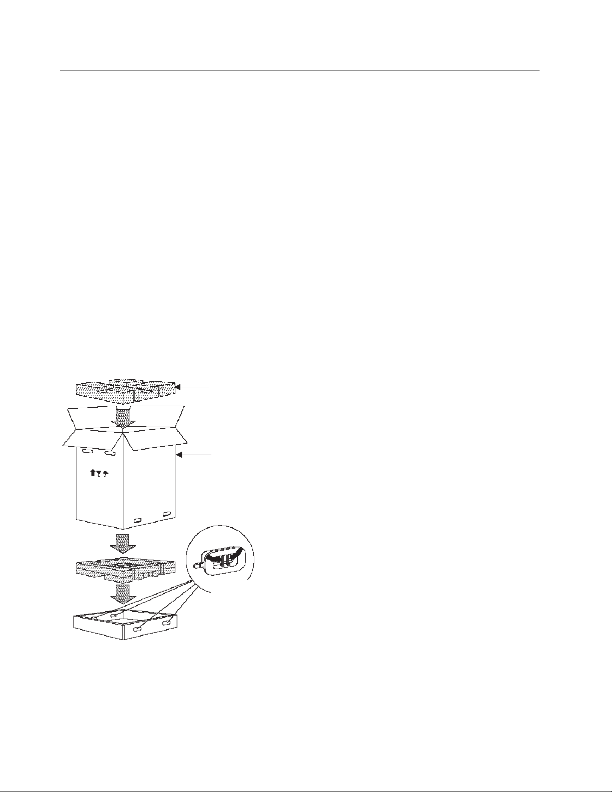
2. Cut the tape that covers the seam on the top of the box and remove the foam packing material. To
remove the foam packing material, pull it straight up.
3. Squeeze and remove the locking inserts at the bottom of the box.
Foam packing
material
Corrugated
sleeve
To remove the locking
inserts, press the inner
latch mechanism together
to release them and then
pull them out.
Figure 1. Unpacking the Switch Shipping Box
4. Remove the corrugated sleeve by pulling it straight up.
5. Pull off the tape from the top of the bag that covers the switch.
6. Remove the bag by pulling it straight up.
7. Remove the power supply grille from the switch shipping box.
4 IBM 8265: Installation Guide
Page 19

8. Place the switch next to the rack or on the table on which it will be installed. Be sure to stand the
switch on its bottom (do not lay the switch down on its top or back).
9. Place all packing materials in the switch shipping box and store the box for future use.
Note: Do not remove blank faceplates from the switch until after the switch has been installed in its
desired location. If modules do not slide easily into the switch, it may be because the switch has
been lifted after some or all blank faceplates have been removed.
Chapter 2. Unpacking the 8265 5
Page 20

Additional Components
The following components are required to operate the 8265 (these components are ordered separately
from the 8265 chassis):
Power supplies (at least two are required), either:
– 415 W AC (Feature Code 8027), or
– 295 W DC –48 V (Feature Code 8026 or 8028)
You cannot mix AC and DC power supplies.
Control Point and Switch (CPSW) module(s), either:
– Feature Code 6501 (standard model), or
– Feature Code 6502 (enhanced model, also referred to as CPSW2), with integrated power control.
One Control Point and Switch module is required for normal operation. A second module made be
installed for redundancy purposes, provided both modules are of the same type.
Controller module(s) (Feature Code 8000)
Only required when the standard CPSW module (Feature Code 6501) is used. May be installed in
conjuction with CPSW2 module (Feature Code 6502) if you prefer power control to be handled by a
Controller module instead of the CPSW2 module.
One Controller module is required for normal operation. A second module made be installed for
redundancy purposes.
A PCMCIA card containing the Control Point and Switch microcode. This card must be inserted in the
Control Point and Switch module before the module is inserted in the 8265. The following cards are
available:
– Base microcode with UNI and IISP functions (Feature Code 6545)
– Enhanced microcode with UNI, IISP, and PNNI functions (Feature Code 6546)
Media modules (at least one is required).
Check that these components are available before commencing the installation of the 8265.
The following components are optional (and are ordered separately from the 8265 chassis):
Rack Mount Kit, Part Number 25H1834.
Cable Management Tray, Part Number 13J8751.
16 MB Memory upgrade (Feature Code 6516) for the standard Control Point and Switch modules
(Feature Code 6501).
Note: This memory upgrade is required when running the enhanced version of microcode.
Documentation CD-ROM (automatically included when PCMCIA card ordered), Feature Code 6508.
Unpacking Components
Unpack components only when you are ready to install them. Instructions and guidelines for unpacking
components are given in each section later in the book.
6 IBM 8265: Installation Guide
Page 21

Chapter 3. Installing the Chassis
This chapter describes step by step instructions to install the chassis in a rack, or on a table or shelf.
Note: The information and procedures in this chapter should be used only by service personnel
CAUTION:
To reduce the possibility of personal injury or serious damage to the switch, install the switch with
the help of a partner.
This is especially important for rack installations because you must hold the switch in place while
securing the switch to the rack.
Copyright IBM Corp. 1994, 1998 7
Page 22

Installing the Cable Management Tray in a Rack
The Cable Management Tray manages module cables at the front of the 8265 by feeding them under the
8265 and out the back. Use is optional. The Cable Management Tray kit includes:
Two rack-mount flanges (used to secure the tray to the rack)
Installation rack-mount hardware (screws and clip nuts)
Cable Management Tray.
This section describes:
Pre-installation guidelines
Installing the Cable Management Tray.
8 IBM 8265: Installation Guide
Page 23
Pre-installation Guidelines
Before installing the cable management tray in a rack, determine which cable management tray rack
mount position is best for you by examining the following:
Location in the rack where the switch will be installed (refer to “Pre-installation Guidelines” on
page 13).
Depth of the rack in to which the switch will be installed.
Space required for ventilation. A minimum of 15 cm (6 in.) is required between the rear of the 8265
and the nearest wall or vertical surface.
Room required for module cables to bend.
Proximity of other devices in the rack and their installation or environmental requirements.
Figure 2 shows cable management tray rack mount positions.
Flush Mount
5/8" (1.6 cm) Recess
2 1/8" (5.4 cm) Recess
2 3/4" (7.0 cm) Recess
Figure 2. Cable Management Tray Rack Mount Positions
Table 2 provides cable management tray rack settings.
Table 2. Rack Mount Settings for Cable Management Tray
Setting Description
Flush mount Mounts the tray flush with the front of the rack.
5/8-inch (1.6 cm) recess Recesses the tray 5/8-inch (1.6 cm) from the front of the rack.
2 1/8-inch (5.4 cm) recess Recesses the tray 2 1/8-inch (5.4 cm) from the front of the rack.
2 3/4-inch (7.0 cm) recess Recesses the tray 2 3/4-inch (7.0 cm) from the front of the rack.
Select any rack position that is at least 28 inches (approximately 71 cm) from the top of the rack or the
next higher unit in the rack.
Be sure to select a rack position that leaves you enough room to install the cable management tray below
the installed switch.
Chapter 3. Installing the Chassis 9
Page 24
Installing the Tray
To install the Cable Management Tray in the selected rack:
1. Attach the two rack mount flanges (supplied) to the Cable Management Tray using the flathead screws
provided (eight, 8-32 x 1/4-inch screws, four per side). Install the screws using a Phillips- head
screwdriver. Installed Cable Management Tray rack mount flanges are shown in Figure 4.
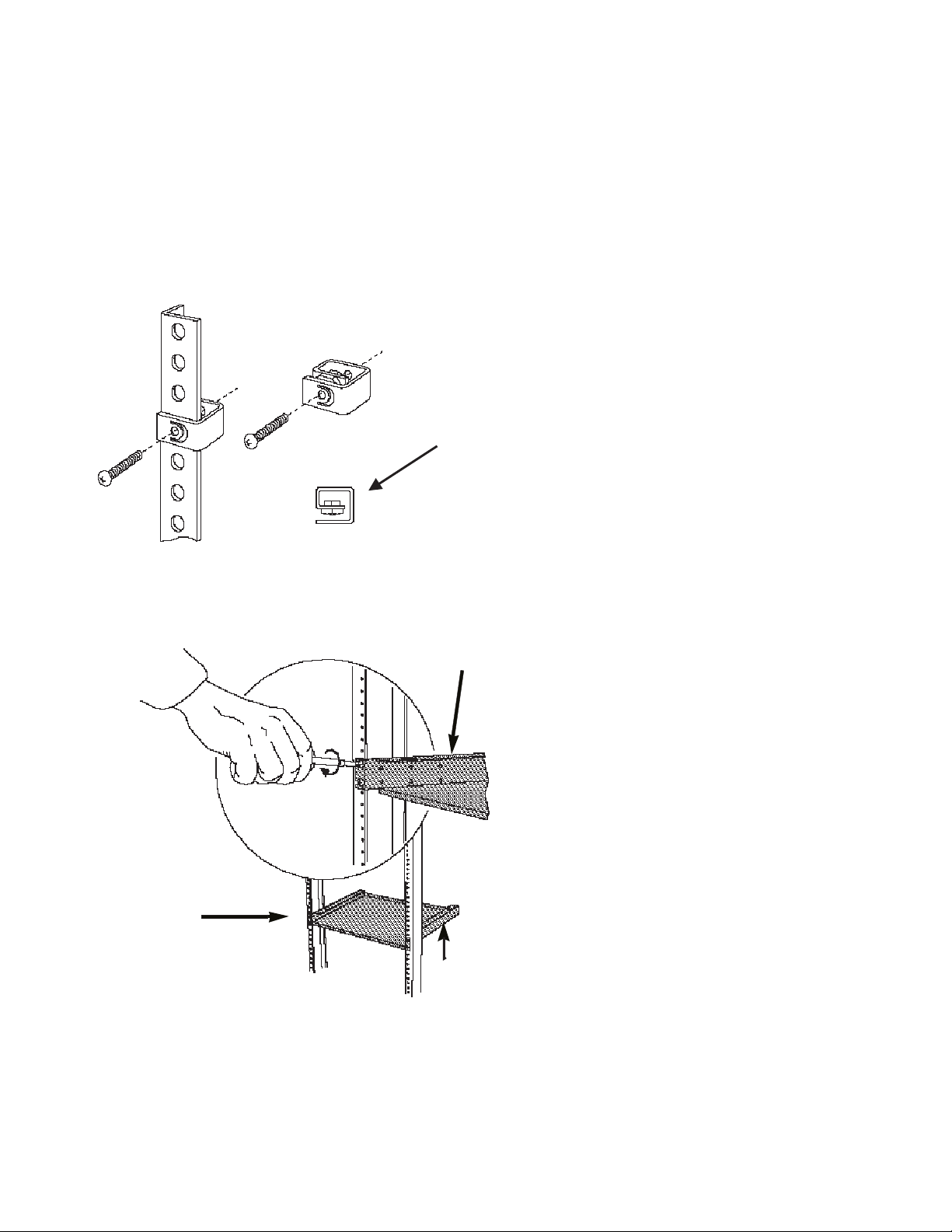
2. Install the clip nuts provided (four) onto the front of the rack at the position where the Cable
Management Tray will be attached. Figure 3 shows the clip nut installation.
Be sure to thread the screw
through this nut to securely
attach each clip nut to the rack.
Figure 3. Installing a Clip Nut in the Rack
Figure 4 shows the Cable Management Tray in the rack.
Installed rack
mount flange
Installed cable
management
tray
Installed rack
mount flange
Figure 4. Installing the Cable Management Tray in a Rack
3. Place the Cable Management Tray in the rack and attach the tray to the front of the rack using the
screws provided (four, 10-32 x 1/2-inch screws). Install the screws with a Phillips head screwdriver.
10 IBM 8265: Installation Guide
Page 25

Installing the 8265 in a Rack
This section describes:
Pre-installation Precautions
Pre-installation Guidelines
Installing the Switch in a Telco Rack
Installing the Switch in a Metric Rack.
Use the following rack mount installation precautions guidelines to ensure safety and optimal performance.
These precautions and guidelines apply to all versions of the switch. Review all guidelines prior to
installation.
All rack mount illustrations provided in this chapter show the switch installed in a Telco rack.
Chapter 3. Installing the Chassis 11
Page 26

Pre-installation Precautions
Before installing the 8265 in an equipment rack, observe the following precautions:
Because the equipment rack environment can cause increased ambient temperatures and reduced air
flow, review the switch specifications and site requirements contained in
Planning and Site Preparation Guide
To ensure mechanical stability and to avoid circuit overloading and improper grounding, follow the rack
manufacturer's instructions for rack installation. If the instructions are unclear, consult a qualified
electrician.
For proper ventilation, install the switch in a rack that has an open back.
With a full complement of modules and load-sharing power supplies, the 8265 Switch weighs
approximately 120 lbs. (54 kg). Therefore, install your switch before you install modules and power
supplies.
, SA33-0460.
IBM 8265 Nways ATM Switch
12 IBM 8265: Installation Guide
Page 27
Pre-installation Guidelines
Before mounting the 8265 in a rack:
1. First make sure the selected rack can support at least three times the weight of a fully- loaded switch.
2. Bolt the rack to the floor.
3. Brace the top of the rack to the wall.
4. Ensure that there is sufficient vertical space in your rack for each 8265 you wish to install.
5. Install patch panels in the rack for easier cable management.
6. Rack mount flanges are set to flush mount at the factory. If desired, change the rack mount flange
position by removing the screws that attach each flange to the switch. When re-installing the rack
mount flanges on the switch, make sure both flanges are set to the same position before you re-install
the screws. Also, make certain that all removed screws are re-installed correctly.
7. When installing the switch, continue to support the weight of the switch until after you have installed
four of the eight screws (two screws per rack mount flange). Install the four remaining screws to fully
secure both rack mount flanges to the rack.
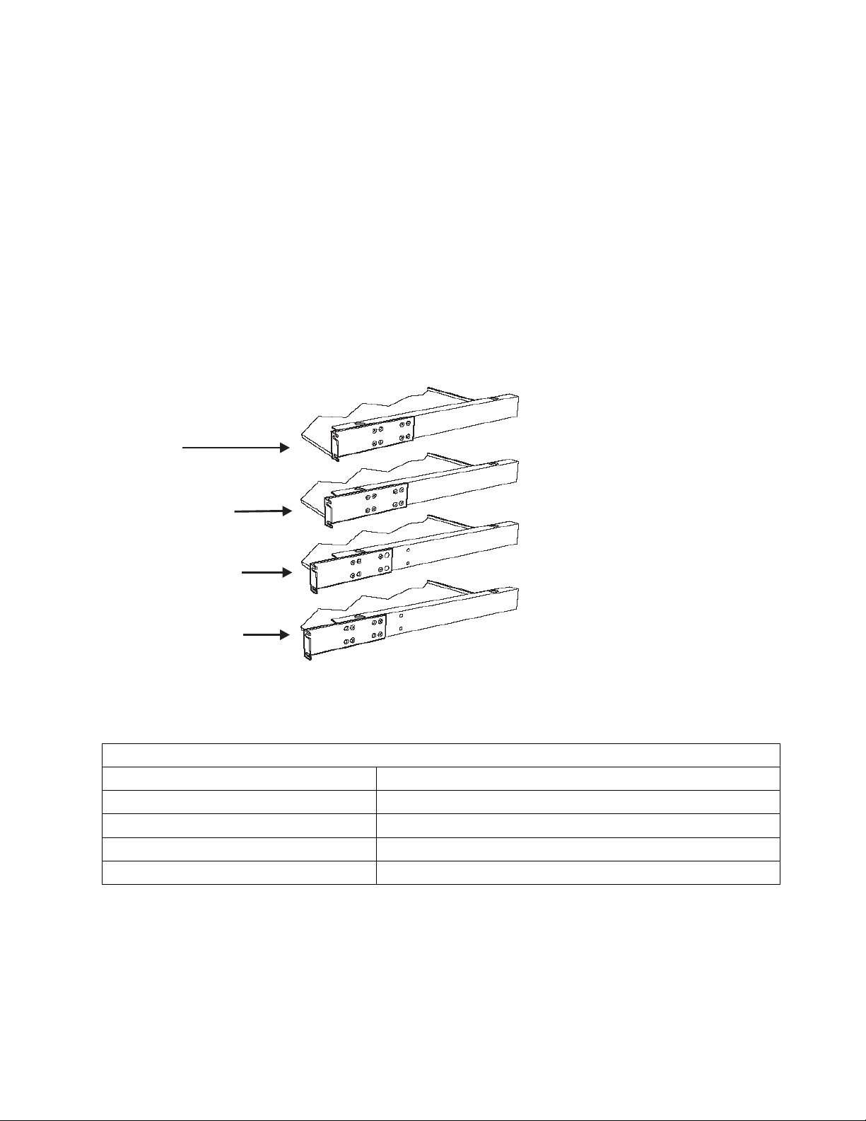
Telco rack and Metric rack screw locations are shown in Figure 5
Screw position (Telco rack)
Screw position (Metric rack)
Screw position (Telco rack)
Screw position (Metric rack)
Screw position (Metric rack)
Screw position (Telco rack)
Screw position (Metric rack)
Screw position (Telco rack)
Figure 5. Telco and Metric Rack Screw Locations
8. Install the Cable Management Tray beneath the switch. The tray is designed to manage the cables
attached to the front of the switch by feeding them under and through the back of the unit. Use of the
cable tray is optional. You can mount the cable tray onto the rack in one of four positions. Mount the
switch using the same rack mount position settings as those used to mount the cable tray.
Chapter 3. Installing the Chassis 13
Page 28

CAUTION:
You can install the switch in the rack either before or after you install the Cable Management
Tray, but the tray must be installed below the switch. Never allow an installed cable tray to
support the weight of the switch. The weight of a switch resting on a rack mounted cable tray
may cause the tray to buckle or separate from the rack. Personal injury may result.
14 IBM 8265: Installation Guide
Page 29

Installing the Switch in a Telco Rack
To install the switch in a Telco rack:
1. Install each of the 8 clip nuts provided onto each side of the front of the rack (4 clip nuts per rack
mount flange). Install each clip nut behind a hole into which you plan to install a trusshead screw.
(See Figure 5 on page 13.)
2. Slide the switch into the rack until both rack mount flanges are flush with the front of the rack.
CAUTION:
Continue to support the weight of the switch until after you have installed four of the eight
screws (2 screws per rack-mount flange).
If you attempt to place the weight of the rack-mounted 8265 switch on fewer than four fully
installed screws, the switch may drop off of the rack. Personal injury or serious damage to the
switch may result.
3. Match the uppermost open slot on each rack mount flange with the corresponding hole on the rack.
Hold the switch in place until you complete step 4. The remaining three open slots on each rack
mount flange automatically line up when each uppermost open slot is matched to a hole on the rack.
4. Secure the switch to the rack with the screws provided (eight, 10-32 x 1/2-inch screws):
a. Install one screw in the uppermost open slot on
b. Install an additional screw in each rack mount flange, and tighten all screws completely before you
allow the weight of the switch to rest (unaided) on the rack. A fully installed screw is flush with the
surface of each rack mount flange.
c. Install the remaining screws in open slots on each rack mount flange (for a total of four screws per
rack mount flange). Install each screw so it is (approximately) equidistant from the screw installed
directly above it and the screw installed directly below it. Tighten the screws completely.
each
of the rack mount flanges.
Chapter 3. Installing the Chassis 15
Page 30

Installing the Switch in a Metric Rack
Note: When installing the switch in a metric rack, install the screws in the
To install the switch in a Metric Rack:
1. Install each of the eight clip nuts provided onto the front of the rack (install four clip nuts per rack
mount flange). Install each clip nut behind a hole into which you plan to install a trusshead screw.
(See Figure 5 on page 13.)
2. Slide the switch into the rack until the switch is flush with the front of the rack.
CAUTION:
Continue to support the weight of the switch until after you have installed four of the eight
screws (2 screws per rack-mount flange).
If you attempt to place the weight of the rack-mounted 8265 switch on fewer than four fully
installed screws, the switch may drop off of the rack. Personal injury or serious damage to the
switch may result.
3. Match the uppermost closed slot on each rack mount flange to the uppermost hole on the rack where
you previously installed a clip nut. Do not attempt to install screws in open slots on either rack mount
flange. Hold the switch in place until you complete step 4
4. Secure the switch to the rack with the screws provided (eight, 10-32 x 1/2-inch screws).
a. Install one screw in the uppermost closed slot on each rack mount flange.
b. Install an additional screw in each rack mount flange, and tighten all screws completely before you
allow the weight of the switch to rest (unaided) on the rack. A fully installed screw is flush with the
surface of each rack mount flange.
closed
slots.
c. Install the remaining screws in closed slots on each rack mount flange (for a total of four screws
per rack mount flange). Install each screw so it is (approximately) equidistant from the screw
installed directly above it and the screw installed directly below it. Tighten all screws completely.
16 IBM 8265: Installation Guide
Page 31

Installing the Switch on a Table or Shelf
Though it is recommended that you install the 8265 switch in a rack, you can also install the switch on a
table or shelf.
CAUTION:
Do not use the Cable Management Tray when installing the switch on a table top or shelf.
If you choose to install the rubber feet, be advised that the switch could tip over under certain
conditions. Hardware damage or personal injury may result.
Safety regulations state that the selected table or shelf must be able to support at least three times
the weight of a fully loaded switch.
To install the 8265 switch on a table or shelf:
1. If you wish to install the rubber feet to the switch, lay the switch on its side on the table or shelf so the
bottom of the switch is accessible.
2. Optionally, remove the rubber feet (4) and the screws supplied (4) from the plastic bag in which they
were shipped and fasten the rubber feet to the bottom of the switch with the screws.
Figure 6 shows how to attach the rubber feet to the bottom of the switch.
Figure 6. Attaching a Rubber Foot to the 8265 Switch
3. Reposition the switch on the table or shelf so it rests squarely on the table or shelf. Ensure module
and power supply slots are unobstructed and easy to reach.
Chapter 3. Installing the Chassis 17
Page 32

18 IBM 8265: Installation Guide
Page 33

Chapter 4. Installing Power Supplies
This chapter describes how to install power supplies in an 8265.
For information on the power requirements for AC and DC power supplies, refer to the
ATM Switch Planning and Site Preparation Guide
, SA33-0460.
IBM 8265 Nways
Figure 7 shows the installation locations for the four power supplies, marked PS1, PS2, PS3, and PS4.
POWER
POWER
SUPPLY
SUPPLY
21
21
4
4
3
3
F
F
A
AN
N
1
1
2
2
3
3
ACT
A
S
STB
CT
T
B
Y
Y
T
T
E
E
M
M
P
P
L
L
E
ED
D
TE
T
E
ST
S
T
P
P
O
O
W
W
R
R
E
ER
E
E
R
S
S
ET
E
T
PS1 PS2 PS3 PS4
Figure 7. 8265 Power Supply Locations
Copyright IBM Corp. 1994, 1998 19
Page 34

Installing an AC Power Supply
You can install power supplies in any of the power supply slots. A factory label located directly below the
power supply slots identifies the slot number associated with each power supply.
To install a power supply:
1. Remove the blank faceplate covering each slot in which you will install a power supply. Keep this
blank faceplate for later use.
2. Set the ON/OFF (I/O ) switch on the front of the power supply you are installing to the OFF (O)
position before inserting the power supply into the switch.
3. Slide the power supply into the selected power supply slot. Push the power supply unit into the switch
until the front panel of the power supply is flush with the front of the switch. The rear power supply
connectors should now be firmly seated into the 8265 power supply connectors.
O
I
Figure 8. Installing an AC Power Supply
4. Fasten the power supply to the 8265 by tightening the two screws on the power supply faceplate.
Ensure that both screws are securely fastened (finger-tight).
5. Plug the power cord into the power supply unit socket.
6. Set the power supply's ON/OFF (I/O) switch to the ON (I) position.
7. Repeat steps 1 through 6 for subsequent power supplies.
20 IBM 8265: Installation Guide
Page 35

Installing a DC Power Supply
This section describes how to prepare and install the -48 Volt DC power supply and power cord in your
8265.
CAUTION:
Only trained electrical service personnel must make connections and disconnections to the -48
Volt DC power source.
A circuit breaker (short-circuit protection) must be set up in the main power source. This circuit
must be grounded to a safety ground. For each power supply use one 20-A protection device to
protect the cabling of the -48 Volt DC power supply against short-circuits.
To comply with UL requirements, the -48 Volt DC Power Supply must only be installed in a
rack-mounted 8265 installed in an enclosed cabinet.
The -48 Volt Power Supply switch only shuts off the output side of the power supply.
Before You Begin
This section describes what you should know before you begin installing the -48 Volt DC Power Supply in
your 8265:
1. Verify that the power source is compatible with the voltage and tolerances specified on the input rating
plate located on the power supply unit. The nominal value is -48 Volt DC, 11 Amps.
2. Remove the following items from the shipping box:
Power supply unit
Power input cable
Bags containing the terminal rings.
The -48 Volt DC power supply ships with 3 bags of terminal rings:
– Part Number AMP 320563, contains 1 terminal ring for only the green/yellow ground wire.
– Part Number AMP 31890, contains 4 terminal rings for the red and black wires.
– Part Number AMP 31880, contains 4 terminal rings for the red and black wires.
The -48 Volt DC power supply ships with different size terminal rings. One terminal ring is for only the
green/yellow ground wire. The remaining terminal rings are used with the red and black wires. Choose
the correct the terminal rings to support your installation.
The AMP part number for the terminal crimping tool is AMP # 58433-2 (this includes the correct
crimping die set). The AMP Die Set part number is 58423-1 (for people that already have the crimping
tool with other dies).
Chapter 4. Installing Power Supplies 21
Page 36

3. Set the power supply ON/STANDBY switch to the Standby position.
Figure 9 shows the front panel of the -48 Volt DC power supply with the ON/STANDBY switch.
Serial Number
Input Rating Label
Warnings Label
STANDBY Position
ON/STANDBY Switch
ON Position
Figure 9. -48 Volt DC Power Supply
Keyed-Connector
22 IBM 8265: Installation Guide
Page 37

Preparing and Installing the DC Input Power Cords
Note: The following terminal ring installation shows how you install terminal rings to the power cord. The
installer should adapt the building DC input and make the power cord connection using the
terminal rings shipped with the power supply or whatever method is necessary to meet system
installation requirements. For compatibility with the building power source, the installer chooses
which size terminals rings are to be crimped on the power cord wires.
To prepare and install the -48 Volt DC input power cords:
1. Obtain the power supply cables that you removed from the shipping boxes. The input power cables
have 3 groups of wires. Each wire is labeled with the corresponding voltage. The 2 red wires are
labeled 48VDC and the 2 black wires are labeled 0VDC.
Figure 10 shows the -48V DC input power cord.
Terminal Ring
2 Black Wires
(0 Volt Return)
Figure 10. -48 Volt DC Input Power Cord
2 Red Wires (-48 Volt DC)
1 Green/Yellow Ground Wire
Safety Label
Keyed-Connector
Note: To comply with UL requirements, the power cords must be routed through a rack or cabinet
raceway to the rack or cabinet distribution panel delivering the -48 Volt DC input power. The
cables may be routed to the back using the cable tray option of the 8265.
2. Fit the terminal rings to each wire of the power cords and tighten them with a crimping tool according
to the AMP rings size. Each wire has a terminal ring at the end.
3. Connect the cable ground wire (green/yellow) to the premises ground system.
CAUTION:
You must install the green/yellow ground wire before installing any of the red or black wires.
4. Take the 2 black wires and connect them to the positive (+) symbol on the power source (zero Volt
return).
Chapter 4. Installing Power Supplies 23
Page 38

5. Take the 2 red wires and connect them to the minus (-) symbol of the power source (-48 Volt).
Figure 11 shows how to connect the red and black wires.
For 0 Volt return
and -48 Volt
Red/Black Wire
Figure 11. Connecting the Red/Black Wires
Terminal Ring
Flat Washer
Screw
6. (Optional). Additional rack grounding can be achieved by connecting a ground cable from the 8265
chassis to the rack.
Figure 12 shows how to connect the additional ground cable, for standard and 'Bellcore' installations.
For Ground Terminal For Ground Terminal
Terminal Ring
Star Washer
Green/Yellow Ground Wire
Figure 12. Connecting the Cable Ground Wire
Screw
Star Washers
Green/Yellow Ground braid
"Bellcore" Installation"Standard" Installation
Tinned braid
or equivalent
Screws
Note: The power source should be labeled with minus (-) and positive (+) symbols.
24 IBM 8265: Installation Guide
Page 39

Installing the DC Power Supply Unit
To install the -48 Volt DC power supply unit:
1. Make certain that the ON/STANDBY switch on the unit is in the STANDBY (O) position.
2. After removing a blank faceplate that covers a power supply slot, carefully slide the power supply into
the selected slot of the 8265 chassis.
3. Fasten the power supply to the 8265 by tightening the two spring-loaded screws on the power supply
faceplate. Ensure that both screws are securely fastened (tighten the screws to 3 to 5 inch pounds).
4. Plug the keyed-connector into the power supply socket.
Figure 13 shows the power supply keyed-connector with strain relief.
Keyed-Connector
Strain Relief
Figure 13. -48 Volt DC Power Supply Keyed-Connector
5. Set the ON/STANDBY switch to the ON (I) position.
6. Repeat steps 1 through 5 for each subsequent power supply.
Chapter 4. Installing Power Supplies 25
Page 40

Installing the Power Supply Bay Grille
This section describes how to install the power supply bay grille for the 8265 switch.
Note: If your installation applies standard GR-63-CORE (Issue 1, October 1995), you should not install
this grille.
To install the power supply bay grille:
1. Remove the power supply bay grille from the switch shipping box.
2. Grasp both ends of the grille and place the two bottom tabs into the notches at the base of the power
supply bay.
3. Flex the grille so the tab on each end of the grille can be fitted into the corresponding notches on the
power supply bay.
4. Still flexing the grille, insert the tabs into each respective notch.
Figure 14. Installing the Power Supply Bay Grille
5. Once the tabs have been inserted in each notch, release the grille to complete the installation.
26 IBM 8265: Installation Guide
Page 41

Chapter 5. Installing Modules
This chapter describes the following:
How to install the 8265 Control Point and Switch module(s)
How to install the 8265 Controller module(s)
Guidelines for installing 8265 media modules
Guidelines for installing 8260 media modules.
Before You Start
Take the following precautions before unpacking any modules:
Do not remove components from their anti-static bags until you are ready to install the modules in the
8265. This avoids the possibility of having electrostatic discharge damage static-sensitive devices on
the components.
Always use a floor strap and grounded mat, or wear a grounded static discharge wrist strap whenever
you inspect or install a module. Alternatively, touch a grounded rack or another source of ground
before handling the module.
Verify that the module (and daughter cards if required) are correct by matching the part number listed
on the side of the shipping carton to the part number you ordered.
Copyright IBM Corp. 1994, 1998 27
Page 42

Unpacking Modules
When unpacking modules, follow these steps:
1. Remove the anti-static bag containing the module from the shipping carton.
2. Remove the module from the anti-static bag and inspect it for damage. Always handle modules by
their faceplates, being careful not to touch the internal components.
If the module appears damaged, put it back in the anti-static bag, and put the bag back into the
shipping carton. Then contact your local IBM dealer or IBM representative.
It is recommended that you retain the shipping carton and anti-static bag in case you later want to
repackage the module for storage or shipment.
28 IBM 8265: Installation Guide
Page 43

Installing the Control Point and Switch Module
Before You Begin
Before installing a Control Point and Switch module:
Make sure that you also have the PCMCIA card containing the Control Point and Switch microcode.
There are two versions, a basic version containing IISP and UNI protocols, and an enhanced version
with additional PNNI protocol. One of these MUST be installed on the module before the module is
installed in the 8265.
If you are installing the memory upgrade for the standard Control Point and Switch module, make sure
that it is to hand.
The memory module must be installed on the Control Point and Switch module before its insertion in
the 8265.
(CPSW2 module only) — Check that the Power Control jumper setting is in the correct position. To
use the integrated power control functions, the FORCE RCTL jumper must be in the OFF (down)
position. If you are using Controller modules for power management, the jumper must be in the ON
(up) position.
Important!: If you are installing two CPSW2 modules, the jumper setting must be the same on both
modules.
Attention: You must not install an 8260 CPSW module into the 8265.
Figure 15 illustrates the PCMCIA card slot, memory bank location, and the location of the Power Control
(FORCE RCTL) jumper (CPSW2 modules only).
PCMCIA Card
DRAM Memory
Banks
FORCE RCTL
Jumper
Figure 15. 8265 Control Point and Switch Module
Chapter 5. Installing Modules 29
Page 44

Installing the PCMCIA Card
To install a PCMCIA card:
1. Remove the card from its packaging.
2. Position the card so that it is just above the slot on the CPSW module, making sure that the edge with
the connectors is inserted first.
3. Slide the card into the slot.
4. Push gently downward until the card clicks into place. If the card does not seat properly, turn the card
over and try again. The card will not click into place when inserted back-to-front.
To remove a PCMCIA card, simply press down on the small lever on the left of the slot.
30 IBM 8265: Installation Guide
Page 45

Installing the Memory Upgrade
To install the memory upgrade:
1. Remove the memory module from its packaging.
2. Locate the end of the module that has a small notch.
3. Position the module above the vacant socket on the CPSW module, making sure that the end with the
notch is facing to the rear of the module.
4. Gently insert the module into the socket at 45 degrees.
5. Push gently downwards on the module until it clips into place.
To remove a memory module, release the clips at either end of the module, then slide the module
upwards gently and lift out.
Chapter 5. Installing Modules 31
Page 46

Installing the Module
To install a CPSW module:
1. Insert the CPSW module into slots 9 and 10, or 11 and 12 of the switch by matching the top and
bottom board guides as you slide the module cleanly into place (by pressing evenly on the top and
bottom of the faceplate).
2. Check that the module is plugged into the connectors on the ATM backplane.
3. Fasten the spring-loaded screws on the top and bottom of the front panel of the module to the chassis
using your finger. Do not over-tighten.
4. If the switch is already powered on, press the LED Test button to ensure that all LEDs are functional
(optional).
5. Repeat the above steps for the second module if you are installing two.
32 IBM 8265: Installation Guide
Page 47

Installing the Controller Module
Controller modules are only required when the standard CPSW module is to be used (Controller module
functionality is in-built in the enhanced CPSW2 module). Controller modules may be installed in
conjunction with a CPSW2 module if you prefer power management to be handled by the Controller
module instead of the CPSW2 module. When using Controller modules with CPSW2 module(s), the
FORCE RCTL jumper on the CPSW2 module(s) must be set to the ON position (see ,Figure 15 on
page 29 for the jumper location).
The 8265 Controller modules must be installed in the Controller module slots. These slots are located at
the lower right front corner of the switch, slot 18 (left) and slot 19 (right). Controller modules are not
designed for installation in any other slot.
The 8265 Controller module bay accommodates up to two Controller modules. Install at least one
Controller module for normal 8265 operation. Install a second Controller module to achieve Controller
module fault-tolerance.
Note: The second Controller module can only act as a backup for another Controller module. It cannot
act as a backup for a CPSW2 module using integrated power control.
Considerations When Installing Two Controller Modules
When two controller modules are to be installed, which module becomes the active depends on whether
the 8265 is powered on or not.
If the 8265 is not powered on, the controller module installed in slot 18 will become the active one
(and the module in slot 19 will become the standby module) when the 8265 is powered on, regardless
of the order in which they are installed.
If the 8265 is already powered on, the first controller module to be installed will become the active
one, irrespective of the slot used. It will also remain the active one when the second module is
installed later.
Installing the Module
To install a Controller module:
1. Remove the Controller module from the shipping carton.
2. Remove the Controller module from the anti-static bag and inspect it for damage. If the module
appears to be damaged, put it back in the anti-static bag, place it in the shipping carton, and contact
your local supplier.
3. Record the serial number and software version of your Controller Module. (Once the switch is
operational, you can view this information by entering the SHOW INVENTORY command at the
terminal prompt.)
4. If the controller slot is covered by a blank faceplate, remove the faceplate by turning the two
spring-loaded screws that hold the faceplate in place, counterclockwise. The Controller bay is located
at the lower right front corner of the switch.
Note: Each 8265 Controller module is equipped with an ejector that helps you to remove the
Controller module. This ejector can be in any position when you install the Controller module.
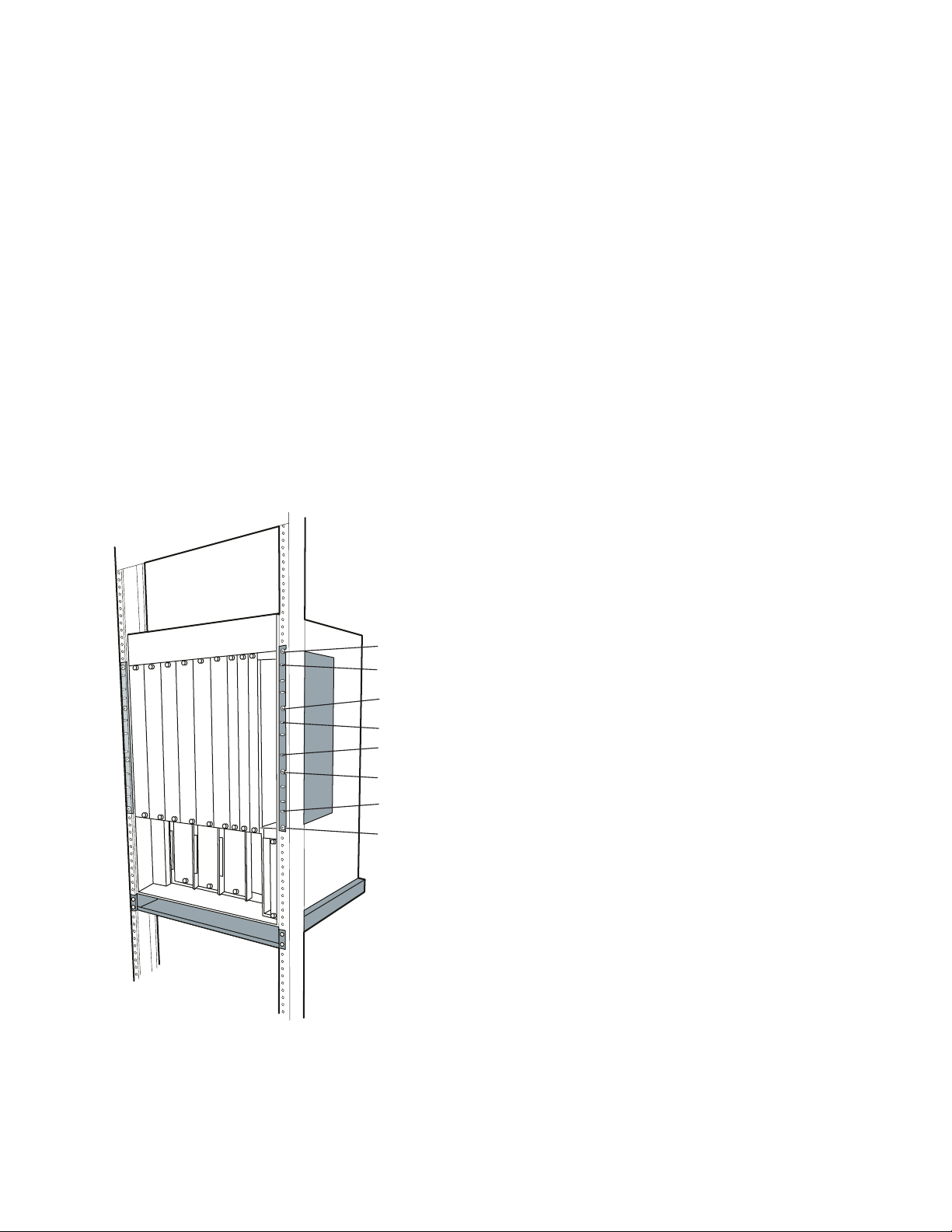
Figure 16 on page 34 shows how to insert a Controller module.
Chapter 5. Installing Modules 33
Page 48

Slide the Controller
Module into the
selected slots as
shown here.
Figure 16. Installing a Controller Module
5. Lock the ejector into place by applying pressure to the Controller module faceplate with one hand as
you pull up on the end of the ejector. Ensure that the Controller module remains fully seated in the
backplane connector as you close the Controller module ejector.
6. Lift the end of the ejector until the ejector locks into place.
7. Complete the installation by hand-turning each of the spring-loaded screws at the top and bottom of
the module in a clockwise direction. Do not overtighten the screws.
8. If you are using the Controller module(s) in conjunction with the CPSW2 module(s), make sure that
the FORCE RCTL jumper on the CPSW2 module is set to the ON position (on both CPSW2 modules
if two are installed).
Attention: To ensure adequate cooling airflow, install blank slot cover plates over
all
empty slots.
34 IBM 8265: Installation Guide
Page 49

Guidelines for Installing 8265 Media Modules
Before installing a media module, refer to the module-specific installation instructions that accompany your
module (See the Media Module Reference Guide). Some media modules require the installation of
daughter cards before the module is installed in the switch).
Note: It is not necessary to power down the switch when installing or removing media modules. You can
install or remove all media modules without disrupting switch operation.
This section describes guidelines for installing media modules. This section contains the following topics:
Cautionary guidelines
Installation guidelines
Guidelines for installing 8260 ATM media modules
Observe these guidelines when handling, installing, or removing an ATM module.
Cautionary Guidelines
Before you begin to install a module, review the following guidelines when handling a module:
Electrostatic discharge (ESD) can damage static-sensitive devices on circuit boards:
– Do not remove the module from its anti-static shielding bag until you are ready to install it.
– To ensure that static charge is removed, touch any installed module's fastener screw before
installing the module. This dissipates charge energy through the chassis to the grounded power
cord.
– Handle the module by the faceplate only.
Do not twist or otherwise force modules into the switch.
Chapter 5. Installing Modules 35
Page 50

Installation Guidelines
This section describes guidelines to follow when installing media modules.
1. 8265 media modules can be installed in slots 1–8 and 12–17. Slots 9, 10, and 11, are reserved for
Control Point and Switch modules.
Note: Slot 12 can be only be used in the following circumstances:
a. No CPSW module is installed in slot 11.
b. If the CPSW2 module is installed, the 8265 must be equipped with the backplane Part
Number 26L0112. Release 4 versions of the 8265 are equipped with this backplane. Older
versions of the 8265 are equipped with backplane Part Number 13J8689 and do not
support media modules in slot 12. The backplane part number can be displayed by
entering the the SHOW INVENTORY VERBOSE command. Alternatively, look for "Release
4" on the label to the left-hand side of the power supplies.
Table 3 lists the 8265 media modules that can be installed.
Table 3. Media Module Slot Availability
Module Feature Code
4-port 155 Mbps (MMF) 6540
4-port 155 Mbps (Flex) 6543
1-port 622 Mbps (MMF) 6511
1-port 622 Mbps (SMF) 6512
WAN 2.5 6561
MSS Server 2.5 5401
2. When deciding which available slot to use, consider the following:
If you intend to also install 8260 ATM modules, note that they can only be installed in slots 1, 3, 5,
and 7. See Table 4 on page 37 for the slot widths of the 8260 modules. Make sure that adjacent
slots are also available if you are installing a 2– or 3–slot module.
Note: 8260 modules can only operate in the 8265 when the standard CPSW module is installed.
They will not operate when the enhanced CPSW2 module is installed.
The media module slots are divided into three heat management areas:
– Slots 1 through 8
– Slots 6 through 13
– Slots 10 through 17.
If an overheat condition is detected (due to a fan failure, for example), then modules within that
area are selectively powered down, according to their power class settings, until the temperature
falls below the overheat threshold (how to set power class settings for modules is described in the
8265 Nways ATM Switch User's Guide
).
You should therefore install your most important modules in different management areas.
3. When installing a media module on which daughter cards are installed, take special care to insert the
host module straight into the slot. This ensures that daughter cards attached to the host module are
not damaged during host module installation.
36 IBM 8265: Installation Guide
Page 51

4. To assure proper installation, match the top and bottom board guides as you slide the module cleanly
into place. Do not attempt to push the module all the way into the switch until you verify that module
ejectors are open.
Note: If the 8265 is powered on, the Error LED on the 4-port 155 Mbps and 1-port 622 Mbps modules
will illuminate when the module is installed. This is because the module detects that there is no
signal present, as there is no cable connection to the module's port(s) at this time. The LED will
extinguish once a connection is made.
Guidelines for Installing 8260 ATM Media Modules
1. 8260 media modules can only operate in the 8265 when the standard CPSW module (Feature Code
6501) is installed. They will not operate with the enhanced version of the CPSW module (Feature
Code 6502).
2. 8260 media modules must only be installed in slots 1, 3, 5, and 7.
Slots 7 can only be used for a 3–slot module when there is no CPSW module installed in slot 9.
3. Some 8260 media modules must have a minimum FPGA level in order to operate in the 8265. The
modules must have this FPGA level, or higher, before being installed in the 8265.
If your 8260 module does not have the specified FPGA level (or higher), upgrade the module before
removing it from the 8260, using MES 5099. For information on how to upgrade FPGA code, refer to
IBM 8260 Nways Multiprotocol Switching Hub, ATM Control Point and Switch Module Installation and
User's Guide
, SA33-0326.
Table 4 lists the modules and the minimum FPGA levels required (if any).
Table 4. Minimum FPGA Levels Required for 8260 ATM Modules
Module Faceplate
Marking
4-port 100 Mbps A4-SC100 1 B50
12-port 25 Mbps A12-TP25 1 C30
2-port 155 Mbps A2-MB155 1 B50
3-port 155 Mbps A3-MB155 1 C31
ATM WAN A2-WAN 1 B50
ATM WAN 2 A8-WAN 1 C32
ATM Carrier A-CMU1 1 B50
ATM Carrier A-CMU2 2 B50
MSS Server A-MSS 2 B50
8271 ATM/Ethernet A-E12LS2 2 none
8271 ATM/Ethernet A-E12LS4 3 none
8272 ATM/Token-Ring A-TR8LS2 2 none
8272 ATM/Token-Ring A-TR8LS4 3 none
8281 ATM LAN Bridge A04MB-BRG 2 B50
Video Distribution A8-MPEG 2 none
Slot Width Required
FPGA Level
Chapter 5. Installing Modules 37
Page 52

38 IBM 8265: Installation Guide
Page 53

Chapter 6. Attaching a Configuration Console
You must attach an ASCII-type terminal to the RS-232 console port on the active CPSW module in order
to perform the initial configuration of the 8265. The connection can either be local or via modem.
If you use the modem cable delivered with the 8265 (Part Number 59G0278), you must also use the
supplied null modem adapter (Part Number 58F2861).
When the EIA-232 terminal attachment has a male connector, the gender changer (Part Number
58G4422) must be used.
1. Verify that the console and modem (if used) meet the factory defaults of the CPSW module. If they are
not compatible, you will not be able to communicate with the module. The default settings are:
9600 baud rate
8 data bits
No parity
1 stop bit.
2. Attach one end of an RS-232 cable to the 9-pin RS-232 console port on the front panel of the CPSW
module). Loop the cable through the Cable Management Tray (if installed) and attach the other end
(9-pin or 25-pin) into the appropriate port on the device.
3. After attaching a console to the CPSW RS-232 console port, make sure that the console is set up for
asynchronous serial communication.
How to set up the configuration console and enter command is described in the
Switch User's Guide
4. After connecting a modem to the console port, configure the modem by following the steps given in
the next section.
, SA33-0456.
IBM 8265 Nways ATM
Copyright IBM Corp. 1994, 1998 39
Page 54

Configuring the Modem
The CPSW module supports the use of dial-in modems with the following requirements:
The modem must be 100% Hayes-compatible
Any valid baud rate (300, 1200, 2400, 9600, 19200) may be used. 9600 is recommended.
The modem must be set to Dumb/Auto Answer mode.
To configure a modem, enter the following commands from the console to which the modem is attached:
1. Type at&F and press Enter (to restore the factory default settings).
2. Type at&dð and press Enter (to ignore changes in DTR status) If you have enabled automatic modem
hangup with the SET TERMINAL HANGUP ENABLE command and want to keep this setting, enter
at&d2and press Enter. This sets the DTR parameter so that hangup remains enabled when DTR
switches from ON to OFF.
3. Type atsð=1 and press Enter (to auto-answer on the first ring).
4. Type atsð? and press Enter (to verify the auto-answer if 001 is returned).
5. Type atq1 and press Enter (to ignore the result codes).
6. Type at&W and press Enter (to save the configuration changes).
7. Type at&Y and press Enter (to define the configuration as the new default).
8. Set the modem to Dumb mode (with command recognition disabled) by following the instructions in
the modem's user guide.
40 IBM 8265: Installation Guide
Page 55

Example Parameter Settings
Table 5 and Table 6 on page 42 show examples of EIA-232 xMM parameter settings for certain emulated
ASCII terminals.
Table 5. Entries for the IBM 3163, 3164, and 3101
Field Name 3163 3164 3101
Operating Mode ECHO ECHO ECHO
Interface RS-232C RS-232C RS-232C
Line Control IPRTS IPRTS IPRTS
Speed (bps) 9600 9600 9600
Parity No No No
Return Character CR CR CR
Stop Bit 1 1 1
Word Length (bits) 8 8 —
Response Time (ms) 100 100 —
Interruption Signal (ms) 500 500 —
A modem can also be used at lower speeds by using the appropriate xMM commands.
8265
Modem
Figure 17. Modem Cable Attachment (Part Number 59G0278)
Chapter 6. Attaching a Configuration Console 41
Page 56

Table 6. Entries for the IBM 3151
Menu Field Name Field Input
1. General Machine Mode 3151
Screen NORMAL
Row and Column 24 x 80
Scroll JUMP
Auto LF OFF
CRT Saver OFF
Line Wrap OFF
Forcing Insert OFF
Tab FIELD
2. Communication Operating Mode NOECHO
Line Speed (bps) 9600
Word Length (bits) 8
Parity NO
Stop Bit 1
Turnaround Character CR
Line Control IPRTS
Break Signal (ms) 170
Send Null Suppress OFF
3. Keyboard Enter RETURN
Return NEW LINE
New Line CR/LF
Send LINE
Insert Character MODE
42 IBM 8265: Installation Guide
Page 57

ASCII Terminal Cabling
8265
Figure 18. ASCII Terminal Cabling
Asynchronous
Terminal
Null Modem
Interposer
P/N 58F2861
Chapter 6. Attaching a Configuration Console 43
Page 58

VT100 Emulation on PS/2
Use emulation VT100 of communication manager to emulate an ASCII terminal.
8265
PS/2
Gender Changer
Interposer
P/N 58G4422
Null Modem
Interposer
P/N 58F2861
Figure 19. PC or PS/2 Cabling
Terminal
44 IBM 8265: Installation Guide
Page 59

Chapter 7. Completing the Installation
This chapter describes the following:
Checking that you have installed all required components.
Powering on the 8265.
Verifying that components are operating correctly.
Checking Your Installation
Use the following table to check that you have installed all the required components. Refer to the relevant
page if you have omitted a component.
Table 7 lists the items to have been installed.
Table 7. Installation Steps
Item Required/Optional See
Cable Management Tray optional page 8
DC power supply power cord preparation required if DC power used page 23
AC or DC power supplies 2 minimum required page 20 or 21
Power supply bay grille optional page 26
Control Point and Switch module(s). 1 minimum required page 29
PCMCIA card for CPSW module required page 30
Memory upgrade for CPSW module optional page 31
Controller module(s) 1 minimum required only when
standard CPSW used
Configuration console required page 39
page 33
Note: You should also have switched each power supply unit to ON.
Copyright IBM Corp. 1994, 1998 45
Page 60

Powering on the 8265
CAUTION:
When one or more power supplies are active, module and power supply slots carry electric
current. To avoid possible electric shock and damage to switch components, do not place hands,
tools, or other objects (other than properly installed modules and power supplies) into exposed
module or power supply slots. Do not allow liquids of any kind to contact exposed slots.
DC Power Source
CAUTION:
Connect the -48 Volt DC power supply to Safety Extra Low Voltage (SELV) only. Carefully read the
safety label attached to the power supply cord you received.
Make certain that the building power source is turned OFF (circuit breaker is in the OFF position).
1. Ensure that the -48 Volt building power source is turned OFF.
2. Plug the power cord for each power supply unit into the wall outlets.
3. Turn on the -48 Volt building power source.
The power supplies should now be fully operational.
AC Power Source
1. Plug the power cord for each power supply unit into the wall outlets.
The power supplies should now be fully operational.
46 IBM 8265: Installation Guide
Page 61

Verifying Your Installation
This section explains how to check that each component of the 8265 is correctly installed:
Power supply units
Fan units
Controller module
Control Point and Switch module
Configuration console.
Refer to the Media Module Reference Guide for information on media modules.
Chapter 7. Completing the Installation 47
Page 62

Verifying Power Supply Operation
To verify normal operation of an installed power supply or supplies, confirm that a power supply fault is not
indicated by checking the Power Supply LEDs.
There are four Power Supply LEDs, one for each power supply. These LEDs are located on the front
panel of the Controller modules and CPSW2 modules. Depending on your installation you should check
the LEDs on:
On the Controller module if you are using the standard CPSW module or the CPSW2 module with
integrated power control disabled (FORCE RCTL jumper set to ON on the CPSW2 module). If you
have two Controller modules installed, you should check the LEDs on the active module.
On the CPSW2 module if you are using the integrated power management functions (FORCE RCTL
jumper set to OFF on the CPSW module). If you have two CPSW2 modules installed, you should
check the LEDs on the active module. If you have CPSW2 modules installed, but have disabled power
management, you must check the LEDs on the active Controller module.
The LEDs are numbered 1 through 4, with 1 indicating the left-most power supply bay, and 4 indicating
the right-most power supply bay.
The LED for each unit installed should be lit. If any of the LEDs blinks or does not light for each installed
power supply when the 8265 is powered up, refer to Appendix A, “Troubleshooting” on page 55.
48 IBM 8265: Installation Guide
Page 63

Verifying Fan Operation
To verify that all fan units are operating normally:
Visually inspect all fans, making sure that each is turning without interruption.
Check that a fan fault is not indicated by checking the FAN LEDs. There are three FAN LEDs, one for
each fan unit. These LEDs are located on the front panel of the Controller modules and CPSW2
modules. Depending on your installation you should check the LEDs:
– On the Controller module if you are using the standard CPSW module or the CPSW2 module with
integrated power control disabled (FORCE RCTL jumper set to ON on the CPSW2 module). If you
have two Controller modules installed, you should check the LEDs on the active module.
– On the CPSW2 module if you are using the integrated power management functions (FORCE
RCTL jumper set to OFF on the CPSW2 module). If you have two CPSW2 modules installed, you
should check the LEDs on the active module. If you have CPSW2 modules installed, but have
disabled power management, you must check the LEDs on the active Controller module.
Each FAN LED should be on. If the LED is off or blinking, refer to Appendix A, “Troubleshooting” on
page 55.
Check that the Temp LED (on the active Controller module or the active Advantage CPSW module,
depending on which is being used for power management) is off, indicating normal 8265 internal
operating temperature.
If the LED is blinking or on, it indicates excessive internal operating temperature. This may mean that:
– One or more fans are not functioning normally
– Ventilation holes are blocked
– Fan exhaust temperature (internal 8265 operating temperature) is above 60 °C, (140 °F).
Fan exhaust temperature
each exhaust fan. Heat produced by circuit boards and power supplies accounts for most of this
warm air. Fan exhaust temperature is measured by a temperature sensor located at the rear of
each fan unit
is the temperature of air inside the 8265 as it passes out the back of
Chapter 7. Completing the Installation 49
Page 64

Verifying Controller Module Operation
To verify Controller module operation:
1. Press the LED test button and check that all LEDs illuminate. Then release the LED test button.
Repeat for the second Controller module if two are installed.
2. Check the STBY (Standby) and Active LEDs.
If one Controller module is installed, check:
a. that the STBY LED is off
b. that the Active LED is on
c. that the Power Supply LED is on for each power supply unit installed
d. that the FAN LEDs are on
e. that the Temperature LED is off.
If two Controller modules are installed, check:
– that the Active LED on the active Controller module is on.
– that the STBY LED on the active Controller module is off.
– that the Active LED on the standby Controller module is off.
– that the STBY LED on the standby Controller module is on.
If any of the LEDs fail the above checks, refer to Table 8 on page 55.
Figure 20 shows the location of the LEDs on the Controller module front panel.
POWER
Power Supply LEDs
SUPPLY
112
3
FAN
4
Power Supply LEDs
Fan1LED
Standby LED
LED Test Button
Reset Button
2
3
STBY
ACTIVE
8000-RCTL
TEMP
LED
TEST
HUB
RESET
Fan2LED
Fan3LED
Active LED
Temperature LED
Figure 20. 8265 Controller Module LEDs
For troubleshooting information, refer to page 55.
50 IBM 8265: Installation Guide
Page 65

Verifying Control Point and Switch Module Installation
You can verify that the Control Point and Switch module is correctly installed by checking the front panel:
The CPU Stop LED should be off.
When the 8265 is powered on (or reset), the Control Point and Switch module is initialized and the
System Status LCD displays the various steps of the initialization
1. INIT - initialization process is running.
2. If diagnostics are enabled, the following steps are shown while testing the first bank of DRAM
memory
– SET1, RFW1, RBW1, BRST.
3. CLR1 - first DRAM memory bank is being cleared.
4. If diagnostics are enabled, the following steps are shown while testing the second bank of DRAM
memory (if installed):
– SET2, RFW2, RBW2, BRST.
5. CLR2 - second DRAM memory bank is being cleared (if installed).
6. LOAD - operational code is being copied from the PCMCIA card into the DRAM.
Once the initialization has completed successfully, the System Status LCD will show either ACTV (on
the active CPSW module) or STBY (on the standby Control Point and Switch module when two are
installed). If neither are displayed, an error was encountered during initialization process:
– If the error was not critical, the code goes in Maintenance Mode and an error code and description
of the error is displayed.
– If the error was critical,---> ERROR is displayed. Press the Display Control button to view an
explanation of the error.
(CPSW2 Module only)
– Press the LED Test button and check that all LEDs illuminate. Then release the button. Repeat on
the second CPSW2 module if two are installed.
If no LEDs are illuminated, power off the 8265, remove the CPSW2 module and check that the
FORCE RCTL jumper is in the correct position:
- OFF (down), if you are using the integrated power control
- ON (up), if you are using Controller modules for power control. Check also that you have at
least one Controller module installed.
If you have two CPSW2 modules installed, check that the jumper setting is the same on both
modules.
– If you are using the integrated power control, on the active CPSW2 module:
- Check that the Power Supply LED is on for each power supply unit installed
- Check that the FAN LEDs are on
- Check that the Temperature LED is off.
If any of the LEDs fail the above checks, refer to Table 8 on page 55.
Figure 21 on page 52 shows the location of the LEDs on the CPSW2 module front panel.
Chapter 7. Completing the Installation 51
Page 66

System Status LCD
Reset LED
132
4
POWER
ATM Reset Button
SUPPLY
FAN 1
FAN 2
FAN 3
TEMP
LED
TEST
Figure 21. 8265 CPSW2 Module LEDs
Display Control Button
Power Supply LED's
FAN LED's
Temp
LED Test
RS-232 Console Port
RJ-45 Ethernet Port
If any of the LEDs fail the above checks, refer to Table 8 on page 55.
52 IBM 8265: Installation Guide
Page 67

Verifying Configuration Console Installation
Once the RS-232 connection is made to the CPSW module:
1. Check that "Press Enter" is displayed at the terminal.
2. After you press Enter, the following message should be displayed:
à ð
ATM Control Point and Switch Module
(c) Copyright IBM Corp. 1997, 1998. All rights reserved.
á
ñ
Chapter 7. Completing the Installation 53
Page 68

54 IBM 8265: Installation Guide
Page 69

Appendix A. Troubleshooting
This chapter offers suggestions for detecting and troubleshooting typical fault conditions in the switch and
for verifying Controller Module/CPSW2 module operation.
Troubleshooting Fault Conditions
Table 8 lists possible troubleshooting you can perform using LEDs. The LEDs listed are located on the
front panel of the Controller modules and CPSW2 modules. Depending on your installation you should
check the LEDs:
On the Controller module if you are using the standard CPSW module or the CPSW2 module with
integrated power control disabled (FORCE RCTL jumper set to ON on the CPSW2 module). If you
have two Controller modules installed, you should check the LEDs on the active module.
On the CPSW2 module if you are using the integrated power management functions (FORCE RCTL
jumper set to OFF on the CPSW2 module). If you have two CPSW2 modules installed, you should
check the LEDs on the active module. If you have CPSW2 modules installed, but have disabled power
management, you must check the LEDs on the active Controller module.
If you cannot correct a fault condition using any of the suggestions provided, contact your local service
representative for assistance.
Table 8 (Page 1 of 2). Troubleshooting Using the LED Indicators
LED State Possible Cause Corrective Action
Power
Supply
(1-4)
Off Power supply not installed. None
LED has failed. Press the LED Test button to verify LED
operation.
Blinking Power supply faulty. 1. Verify that the outlet is supplying
power.
2. Verify that the power cord is plugged in
at both ends and that the cord is
appropriate for your country's line
voltage.
3. Verify that the power switch on the
power supply is set to the ON position.
4. Verify that the power supply is fully
seated in the backplane connectors.
5. Verify that the power supply is not
overloaded. Set the power supply
switch to the OFF position, wait a few
moments, then set the power supply
switch to the ON position.
6. Check that the power supply
connectors on the backplane are not
damaged.
7. Replace the power supply if the
suggestions presented above do not
correct the problem (see page 61).
Copyright IBM Corp. 1994, 1998 55
Page 70

Table 8 (Page 2 of 2). Troubleshooting Using the LED Indicators
LED State Possible Cause Corrective Action
FAN (1-3) Off Fan is not installed or LED is
faulty.
Blinking Fan unit is malfunctioning or not
operational.
TEMP Off Switch temperature is normal, or
the LED is faulty.
Blinking Temperature in the switch is
higher than the allowable limit.
ACTIVE On Controller/CPSW module is in
Active mode.
Off Controller/CPSW module is in
Standby mode.
LED is faulty. Press the LED Test button to determine if
STBY On Controller/CPSW module is in
Standby mode.
Off LED is faulty. Press the LED Test button to determine if
Controller/CPSW module fuse
has blown.
Blinking Controller/CPSW module is
faulty.
Install fan unit or press the LED Test
button to determine if the LED is functional.
Replace the fan unit (see page 66).
Press the LED Test button to determine if
the LED is functional.
1. Verify that all fan units are operating
normally and that nothing is blocking
air flow through the front of the switch.
If air flow is blocked, heat build-up may
cause an overheat condition.
2. Verify that the required number of fan
units has been installed (never operate
the switch with fewer than two installed
and functioning fan units).
3. Verify that there is at least 3 inches (8
cm) of space behind the switch for
proper air flow. If air flow is blocked,
heat build-up may cause an overheat
condition.
4. Verify that all empty slots contain a
blank faceplate.
5. Lower the room temperature. Even if
all installed fan units are functioning
normally, excessively warm room air
circulated by installed fans may fail to
adequately cool the switch and
installed modules.
None.
Verify that the Standby LED is illuminated.
the LED is functional.
None.
the LED is functional.
Replace the module.
Reset the Standby Controller/CPSW
module. If a reset does not correct the
problem, replace the module.
56 IBM 8265: Installation Guide
Page 71

Specific CPSW2 Module Problems
Problems may occur when a CPSW2 module is installed with an incorrect power control jumper (FORCE
RCTL) setting. The setting is incorrect if:
The jumper is set to ON (up) and no controller module is installed.
The jumper setting differs from that of an already installed CPSW2 module.
The problems may occur:
after powering on the 8265
when inserting the CPSW2 module while the 8265 is powered on (hot-plugging).
To avoid these problems, you must ensure that the jumper setting on the CPSW2 module being installed
is correct, and, if applicable, matches that of the currently installed module. To check the current setting
on the active CPSW2 module without removing the module, enter the SHOW POWER ALL command.
Problems After Power-On
1. If a CPSW2 is installed with the FORCE RCTL jumper set to ON (up), and no Controller module is
installed:
The LEDs on the CPSW2 module will not illuminate, even when the TEST LED button is pressed.
Media modules cannot be connected to the network or enabled.
To resolve this problem you must:
a. Power off the 8265.
b. Either:
Install a Controller module should you not wish to use the integrated power control of the
CPSW2 module, or
Remove the CPSW2 module and move the jumper to the OFF (down) position. Then re-install
the module
c. Power on the 8265.
2. When two CPSW2 modules are installed with different jumper settings:
If the active CPSW2 module has an incorrect jumper setting:
– The LEDs on the (newly) active CPSW2 module will not illuminate, even when the TEST LED
button is pressed.
– Media modules cannot be connected to the network or enabled.
This occurs regardless of the setting on the second (standby) CPSW2 module.
If the standby CPSW2 module has an incorrect jumper setting:
– The 8265 will be operational provided that the active CPSW2 module's jumper position in the
correct (ON if Controller module installed). However, the 8265 will not be able to switch to the
backup CPSW2 module. When this is attempted:
- The LEDs on the (newly) active CPSW2 module will not illuminate, even when the TEST
LED button is pressed.
- Media modules cannot be connected to the network or enabled.
Should this problem occur, you must
a. Power off the 8265
Appendix A. Troubleshooting 57
Page 72

b. Remove the CPSW2 that has the incorrect jumper setting
c. Set the jumper to the correct position
d. Re-install the CPSW2 module
e. Power on the 8265.
Problems When Hot-Plugging: When installing CPSW2 modules into an already powered-on
8265, the following problems will occur if the power control jumper is in the incorrect position:
1. If the jumper is set to the ON (up) position, and you do not have a Controller module installed:
The LEDs on the CPSW2 module will not illuminate, even when the TEST LED button is pressed.
Media modules cannot be connected to the network or enabled.
To resolve this problem you must:
a. Power off the 8265.
b. Either:
Install a Controller module should you not wish to use the integrated power control of the
CPSW2 module, or
Remove the CPSW2 module and move the jumper to the OFF (down) position. Then re-install
the module
c. Power on the 8265.
2. If the jumper is set to the OFF position, but a Controller module is already installed:
a. Power off the 8265.
b. Either:
Install a Controller module should you not wish to use the integrated power control of the
CPSW2 module, or
Remove the CPSW2 module and move the jumper to the OFF (down) position. Then re-install
the module
c. Power on the 8265.
The CPSW2 module cannot take over power control from the Controller module.
Media modules cannot be connected to the network or enabled.
To resolve this problem you must:
a. Power off the 8265.
b. Either:
Remove the Controller module, should you wish to use the integrated power control functions
of the CPSW2 module, or
Remove the CPSW2 module and move the jumper to the ON (up) position. Then re-install the
module
c. Power on the 8265.
58 IBM 8265: Installation Guide
Page 73

Appendix B. Maintenance
This appendix describes the routine maintenance you should perform to keep your 8265 working at its
best. This appendix also provides instructions for replacing defective power supplies and fan units. The
following maintenance procedures are discussed:
Routine Maintenance
Replacing a Defective Power Supply
Replacing a Defective Fan Unit
Replacing a Defective Controller module.
Note: There are no user-serviceable parts on either the load-sharing power supplies or the fan units. If
these components fail, remove them as described in this Appendix and return them to your
supplier. Keep replacement power supply units and fan units at your site so they are available if
needed.
Copyright IBM Corp. 1994, 1998 59
Page 74

Routine Maintenance
On a regular basis, inspect your 8265 to verify that:
All blank 8265 faceplates are securely attached to the chassis.
At least two fans are running.
Attention: If only two fans are operational, system operation is not affected. However, you should
schedule the defective fan for prompt replacement. If fewer than two fans are operational, power off
the 8265 immediately. Do not attempt to power on again until at least two operational fans have been
installed. You should normally run the 8265 with a full complement of three fans.
Ventilation to the 8265 is unobstructed.
CPSW module, Controller module (if installed), and media module LEDs are functioning normally and
show normal readings.
All modules are securely seated in the backplane and firmly attached to the chassis.
Power requirements for all installed modules are met by the power supplies.
Power cords from each power supply are not frayed or damaged.
Cables running from each installed module are in good condition.
If rack mounted, the 8265 and the cable tray are securely attached to your rack.
60 IBM 8265: Installation Guide
Page 75

Replacing a Defective Power Supply
This section describes how to replace the following:
AC Power Supply
-48 Volt DC Power Supply.
The 8265 can accommodate up to four modular load-sharing AC or DC power supplies.
Note: When replacing a power supply, you must leave enough supplies running at all times to satisfy the
requirements of installed modules. If removal of a defective, but still functioning, power supply will
not cause a power deficit in the 8265, you can remove the faulty supply without losing power to a
module or modules. Before attempting to remove a power supply from the chassis, enter the
SHOW POWER BUDGET command to display current power conditions for the 8265.
Appendix B. Maintenance 61
Page 76

Replacing an AC Power Supply
CAUTION:
To avoid electric shock, be sure to set the faulty power supply's ON/OFF switch (I/O) to the OFF
(O) position, and to disconnect the power cord from both the power supply and the wall outlet
before attempting to remove the power supply from the chassis.
To replace a defective AC power supply:
1. If installed, remove the power supply bay grille to gain access to the power supply bay.
2. Set the defective power supply's ON/OFF switch (I/O) located on the front of the supply to the OFF
(O) position.
3. Remove the power cord from the wall outlet.
4. Remove the power cord from the power supply socket.
5. Loosen the spring-loaded screws that secure the power supply to the front of the 8265.
6. Pull the power supply straight out from the chassis, making certain you do not damage the connectors
on the rear of the supply or those on the power switching board.
7. Remove the replacement power supply from its shipping box and set the power supply's ON/OFF (I/O)
switch to the OFF (O) position.
CAUTION:
Be sure to use the same power type (AC) as the removed power supply.
8. Carefully slide the power supply into the selected power supply slot (the same slot from which the
defective supply was removed, or any other available power supply slot).
Figure 22 shows how to insert the power supply.
Figure 22. Replacing a Defective Power Supply
9. Hand-tighten the spring-loaded screws that secure the power supply to the front of the 8265.
62 IBM 8265: Installation Guide
Page 77

10. Plug the power cord into the socket on the power supply.
11. Plug the power cord into the wall outlet.
12. Set the power supply's ON/OFF switch (I/O) to the ON (I) position. The replacement power supply is
now fully operational.
13. Optionally, install the power supply bay grille (for installation instructions, refer to page 26).
14. Check the Power Supply LEDs (on the active Controller module, if installed, or active CPSW2 module)
to verify that the replacement power supply is functioning normally. All LEDs for installed power
supplies should be illuminated to indicate normal operation.
Appendix B. Maintenance 63
Page 78

Replacing a -48 Volt DC Power Supply
Follow these steps when removing the -48 Volt DC power supply without disconnecting the power cord.
See page 65 for information on replacing the -48 Volt DC power cable.
CAUTION:
Only trained electrical service personnel must make disconnections to the -48 Volt DC power
source.
1. If installed, remove the power supply bay grille to gain access to the power supply bay.
2. Set the defective power supply's ON/STANDBY switch to the STANDBY (O) position.
3. Turn off the power source circuit breaker, protecting the power supply you want to remove.
4. Unplug and remove the keyed cable connector from the power supply socket.
5. Loosen the spring-loaded screws on the power supply faceplate.
6. Carefully pull out the power supply from the slot of the chassis.
7. Remove the replacement power supply from its shipping box and set the power supply's
ON/STANDBY switch to the STANDBY (O) position.
8. Plug the keyed-connector into the power supply socket.
9. Carefully slide the power supply into the selected power supply slot (the same slot from which the
defective supply was removed, or any other available power supply slot).
CAUTION:
Be sure to use the same power type (DC) as the removed power supply. Do not mix AC and DC
power supplies.
10. Hand-tighten the spring-loaded screws that secure the power supply to the front of the switch.
11. Set the power supply's ON/STANDBY switch to the ON (I) position. The replacement power supply is
now fully operational.
12. Optionally, install the power supply bay grille (for installation instructions, refer to page 26.
13. Check the Power Supply LEDs (on the active Controller module, if installed, or active CPSW2 module)
to verify that the replacement power supply is functioning normally. All LEDs for installed power
supplies should be illuminated to indicate normal operation.
64 IBM 8265: Installation Guide
Page 79

Replacing a -48 Volt DC Power Supply Cable
CAUTION:
Only trained electrical service personnel must make disconnections to the -48 Volt DC power
source.
Follow these steps when replacing a -48 Volt DC power cord:
1. If installed, remove the power supply bay grille to gain access to the power supply bay.
2. Set the power supply ON/STANDBY switch to the STANDBY (O) position.
3. Turn off the power source circuit breaker, protecting the power supply whose cable you are replacing.
4. Unplug and remove the keyed cable connector from the power supply socket.
5. Disconnect the 2 red wires from the -48 Volts (- symbol).
6. Disconnect the 2 black wires from the 0 Volt (zero Volt) return (+ symbol).
7. Disconnect the cable ground wire from the terminal ground lugs.
8. Remove the cable.
9. Prepare a new cable as described in “Preparing and Installing the DC Input Power Cords” on
page 23.
10. Plug the keyed-connector into the power supply socket.
11. Set the power supply's ON/STANDBY switch to the ON (I) position.
12. Turn on the power source circuit breaker.
Appendix B. Maintenance 65
Page 80

Replacing a Defective Fan Unit
This section describes how to replace defective fans for the 8265.
The 8265s are shipped with three installed fan units (Part Number 25H1798). For normal operation, at
least two of these dedicated fan units must be running at all times. Power supply fans help to ventilate the
8265, but they are not designed to act as a substitute for dedicated fan units.
Attention: If more than one fan unit malfunctions, power off the 8265 immediately and do not attempt to
power up again until you have installed at least two fully functional fan units. To ensure optimal 8265
operation, always run the 8265 with a full complement of three fan units.
If only one fan unit malfunctions, you do not need to power off the 8265 before removing and replacing the
defective unit.
To replace a defective fan unit:
1. Remove and save the four corner screws that attach the fan unit to the rear of the 8265.
2. Carefully pull the fan unit straight out from the 8265 fan bay and, before completely removing the fan,
grasp the four-position fan connector cable and disconnect it from the 8265 (see Figure 23).
Fan Unit
Fan Connector
Cable
Fan Connector
Screw (one at each comer)
Figure 23. Replacing a Defective Fan Unit
3. Remove the replacement fan unit from its shipping box and carefully slide the fan into the slot formerly
occupied by the faulty unit. Connectors on the installed fan must be firmly seated in the corresponding
8265 connectors.
Note: The fan begins rotating the moment the unit is plugged in.
4. Verify that the replacement fan is flush with the back of the 8265.
5. Replace the four screws that secure the fan unit to the rear of the 8265.
6. Visually inspect all installed fans to verify that each is turning without interruption.
66 IBM 8265: Installation Guide
Page 81

7. Check the Fan LEDs (on the active Controller module, if installed, or active CPSW2 module) to
confirm that all fan units are indeed functioning normally. LEDs for installed fans should be illuminated
to indicate normal operation.
Appendix B. Maintenance 67
Page 82

Replacing a Defective Controller Module
Note: In a switch with two installed Controller modules, removal of the active Controller module causes a
fast reset (the standby Controller module becomes the active Controller module). In a switch with
one installed Controller module, removal of the Controller module causes the switch to go down.
To remove a Controller Module:
1. Loosen the screws at the top and bottom of the module faceplate until the screws disconnect from the
switch.
2. Grasp the end of the module ejector at the lower left corner of the faceplate, and pull it down. This
action causes the ejector to exert pressure on the switch, forcing the Controller Module out of the slot
so its faceplate can then be grasped.
3. Grasp the faceplate and pull the Controller module straight out of the slot.
Note: If you have a standby Controller module installed, make sure the Standby LED (STBY) is ON
before attempting to remove the active Controller module.
To insert a replacement module, see page 33.
68 IBM 8265: Installation Guide
Page 83

Appendix C. Notices
References in this publication to IBM products, programs, or services do not imply that IBM intends to
make these available in all countries in which IBM operates.
Any reference to an IBM product, program, or service is not intended to state or imply that only IBM's
product, program, or service may be used. Any functionally equivalent product, program, or service that
does not infringe any of IBM's intellectual property rights may be used instead of the IBM product,
program, or service. Evaluation and verification of operation in conjunction with other products, except
those expressly designated by IBM, is the user's responsibility.
IBM may have patents or pending patent applications covering subject matter in this document. The
furnishing of this document does not give you any license to these patents. You can send license
inquiries, in writing, to the IBM Corporation, IBM Director of Licensing, 500 Columbus Avenue, Thornwood,
New York 10594, U.S.A.
Product Page/Warranties
The following paragraph does not apply to the United Kingdom or to any country where such
provisions are inconsistent with local law.
INTERNATIONAL BUSINESS MACHINES CORPORATION PROVIDES THIS PUBLICATION "AS IS" WITHOUT
WARRANTY OF ANY KIND, EITHER EXPRESS OR IMPLIED, INCLUDING, BUT NOT LIMITED TO, THE
WARRANTIES OF MERCHANTABILITY OR FITNESS FOR A PARTICULAR PURPOSE.
Some states do not allow disclaimer of express or implied warranties in certain transactions, therefore this
statement may not apply to you.
Copyright IBM Corp. 1994, 1998 69
Page 84

Statement of Limited Warranty
The warranties provided by IBM in this Statement of Limited Warranty apply only to Machines you
originally purchase for your use, and not for resale, from IBM or an IBM authorized reseller. The term
"Machine" means an IBM machine, its features, conversions, upgrades, elements, or accessories, or any
combination of them. Machines are subject to these terms only if purchased in the United States or Puerto
Rico, or Canada, and located in the country of purchase. If you have any questions, contact IBM or your
reseller.
Production Status
Each Machine is manufactured from new parts, or new and serviceable used parts (which perform like
new parts). In some cases, the Machine may not be new and may have been previously installed.
Regardless of the Machine's production status, IBM's warranty terms apply.
The IBM Warranty
IBM warrants that each Machine 1) is free from defects in materials and workmanship and 2) conforms to
IBM's Official Published Specifications. IBM calculates the expiration of the warranty period from the
Machine's Date of Installation. The date on our receipt is the Date of Installation, unless IBM or your
reseller informs you otherwise.
During the warranty period, IBM or your reseller will provide warranty service under the type of service
designated for the Machine and will manage and install engineering changes that apply to the Machine.
IBM or your reseller will specify the type of service.
For a feature, conversion, or upgrade, IBM or your reseller may require that the Machine on which it is
installed be 1) the designated, serial-numbered Machine and 2) at an engineering-change level compatible
with the feature, conversion, or upgrade. Some of these transactions (called "Net-Priced" transactions)
may include additional parts and associated replacement parts that are provided on an exchange basis. All
removed parts become the property of IBM and must be returned to IBM.
Replacement parts assume the remaining warranty of the parts they replace.
If a Machine does not function as warranted during the warranty period, IBM or your reseller will repair or
replace it (with a Machine that is at least functionally equivalent) without charge. If IBM or your reseller is
unable to do so, you may return it to your place of purchase and your money will be refunded.
If you transfer a Machine to another user, warranty service is available to that user for the remainder of
the warranty period. You should give your proof of purchase and this Statement to that user.
70 IBM 8265: Installation Guide
Page 85

Warranty Service
To obtain warranty service for the Machine, you should contact your reseller or call IBM. In the United
States or Canada, call IBM at 1-800-IBM-SERV (426-7378). You may be required to present proof of
purchase.
Depending on the Machine, the service may be 1) a "Repair" service at your location (called "On-site") or
at one of IBM's or a reseller's service locations (called "Carry-in") or 2) an "Exchange" service, either
On-site or Carry-in.
When a type of service involves the exchange of a Machine or part, the item IBM or your reseller replaces
becomes its property and the replacement becomes yours. The replacement may not be new, but will be
in good working order and at least functionally equivalent to the item replaced.
It is your responsibility to:
1. Obtain authorization from the owner (for example, your lessor) to have IBM or your reseller service a
Machine that you do not own.
2. Where applicable, before service is provided:
a. follow the problem determination, problem analysis, and service request procedures that IBM or
your reseller provide,
b. secure all programs, data, and funds contained in a Machine,
c. inform IBM or your reseller of changes in a Machine's location, and
d. for a Machine with exchange service, remove all features, parts, options, alterations, and
attachments not under warranty service. Also, the Machine must be free of any legal obligations or
restrictions that prevent its exchange; and
3. Be responsible for loss of, or damage to, a Machine in transit when you are responsible for the
transportation charges.
Extent of Warranty
IBM does not warrant uninterrupted or error-free operation of a Machine.
Misuse, accident, modification, unsuitable physical or operating environment, improper maintenance by
you, or failure caused by a product for which IBM is not responsible may void the warranties.
THESE WARRANTIES REPLACE ALL OTHER WARRANTIES, EXPRESS OR IMPLIED, INCLUDING,
BUT NOT LIMITED TO, THE IMPLIED WARRANTIES OF MERCHANTABILITY AND FITNESS FOR A
PARTICULAR PURPOSE. HOWEVER, SOME LAWS DO NOT ALLOW THE EXCLUSION OF IMPLIED
WARRANTIES. IF THESE LAWS APPLY, THEN ALL EXPRESS AND IMPLIED WARRANTIES ARE
LIMITED IN DURATION TO THE WARRANTY PERIOD. NO WARRANTIES APPLY AFTER THAT
PERIOD.
In Canada, warranties include both warranties and conditions.
Some jurisdictions do not allow limitations on how long an implied warranty lasts, so the above limitation
may not apply to you.
Appendix C. Notices 71
Page 86

Limitation of Liability
Circumstances may arise where, because of a default on IBM's part (including fundamental breach) or
other liability (including negligence and misrepresentation), you are entitled to recover damages from IBM.
In each such instance, regardless of the basis on which you are entitled to claim damages, IBM is liable
only for:
1. Bodily injury (including death), and damage to real property and tangible personal property; and
2. The amount of any other actual loss or damage, up to the greater of $100,000 or the charge for the
Machine that is the subject of the claim.
Under no circumstances is IBM liable for any of the following:
1. Third-party claims against you for losses or damages (other than those under the first item listed
above);
2. Loss of, or damage to, your records or data; or
3. Economic consequential damages (including lost profits or savings) or incidental damages, even if IBM
is informed of their possibility.
Some jurisdictions do not allow the exclusion or limitation of incidental or consequential damages, so the
above limitation or exclusion may not apply to you.
This warranty gives you specific legal rights and you may also have other rights which vary from
jurisdiction to jurisdiction.
72 IBM 8265: Installation Guide
Page 87

Warranty and Maintenance Service
To obtain warranty or maintenance service for this machine, contact your reseller or call IBM:
In the U.S.A; or Canada, 1-800-IBM-SERV (426-7378)
For other countries, see the following list:
Country Code Telephone Number (from
outside of country)
Australia 61 29 35 44 000 13 24 26
Austria 43 11 70 60 11 70 63 630
Belgium 32 22 25 25 25 02 22 52 525
Denmark 45 45 96 50 50 80 31 10 10
Finland 358 94 591 98 00 42 60
France 33 23 85 57 777 08 01 63 12 13
Germany 49 70 31 15 27 20 01 80 52 53 553
Greece 30 16 88 12 20 16 80 17 00
Ireland 353 16 60 37 44 01 66 03 744
Israel 972 36 97 85 00 17 70 22 38 88
Italy 39 39 60 07 666 16 78 20 094
Japan 81 12 00 35 555 01 20 03 55 55
Korea 82 82 27 84 08 04
Netherlands 31 20 51 35 151 02 05 13 51 51
New Zealand 64 45 76 59 99 08 00 73 32 22
Norway 47 66 99 80 00 80 01 00 10
Portugal 351 17 91 50 00 17 91 51 15
Spain 34 13 87 66 11 90 11 00 000
South Africa 27 11 30 29 700 08 00 12 81 28
Sweden 46 87 93 10 00 02 03 11 010
Switzerland 41 16 43 66 33 08 00 55 54 54
Turkey 90 21 22 80 09 00 02 12 28 00 900
United Kingdom 44 17 05 49 29 49 09 90 42 64 26
Telephone Number (from
outside of country)
For countries that are not in the preceding list, contact your IBM Representative or your Country
Contact at the following Web server:
http://www.ibm.com/Assist
Select your country and click on Go.
For information about other services IBM can offer you, connect to the following Web server:
http://www.as.ibm.com
Note: When calling for service of this machine, you will be required to provide the following information:
'compact'.
Machine Type: 8265
Appendix C. Notices 73
Page 88

Models: 17S
Serial Number: Located on the 8265 chassis label.
74 IBM 8265: Installation Guide
Page 89

Industry Standards Reflected in This Product
The IBM 8265 Nways ATM Switch is designed according to the specifications of the following industry
standards as understood and interpreted by IBM as of October 1992.
International Organization for Standardization (ISO)
ISO 8802/1
ISO 8802/3
ISO 8802/5
IEEE (Institute of Electrical and Electronic Engineers)
802.1 Local area network (LAN) management and Internet working
802.3 Carrier sense multiple access and collision detection
802.5 Token passing ring
ANSI (American National Standard Institute)
The IBM Fiber Distribution Data Interface (FDDI) network is an implementation of the American National
Standards Institute (ANSI) X3T9.5 family of standards.
The IBM base standards for the implementation of the FDDI are:
ANSI X3.166-1990, FDDI physical layer medium-dependent (PMD), ISO 93/4-3
ANSI X3.148-1988, FDDI token-ring physical layer protocol (PHY), ISO 93/4-1
ANSI X3.139-1987, FDDI token-ring media access control (MAC)
ANSI X3.T9, 5/84-49 RFC 1285 FDDI station management (SMI).
ITU-T (International Telecommunications Union - Telecommunication)
The IBM standards for the implementation of ATM are:
Q.2110 Service Specific Connection-Oriented Protocol (SSCOP)
Q.2130 Service Specific Coordination Function (SSCF)
ATM Standards
The IBM 8265 Nways ATM Switch complies with the following ATM standards:
ATM User-Network Interface (UNI) Specifications V3.0, V3.1, and V4.0 ATM Forum
ATM Interim Inter-Switch Signalling (IISP), ATM Forum
ATM Public Network-to-Network Interface (PNNI) Phase 1, ATM Forum
LAN Emulation over ATM Specifications V1.0, ATM Forum
Q.2110 Service Specific Connection-Oriented Protocol (SSCOP), ITU, March 17, 1994
Q.2130 Service Specific Coordination Function (SSCF) for support of signaling at the user-network
interface, March 17, 1994
RFC1577 — Classical IP and ARP (Address Resolution Protocol over ATM.
Appendix C. Notices 75
Page 90

European Union (EU) Statement
This product is in conformity with the protection requirements of EU Council Directive 89/336/EEC on the
approximation of the laws of the Member States relating to electromagnetic compatibility. IBM can not
accept responsibility for any failure to satisfy the protection requirements resulting from a
non-recommended modification of the product, including the fitting of non-IBM option cards.
Year 2000 Statement
This product is Year 2000 ready. When used in accordance with its associated documentation, is capable
of correctly processing, providing, and/or receiving date data within and between the 20th and 21st
centuries, provided all other products (for example, software, hardware, and firmware) used with the
product properly exchange acurate date data with it.
76 IBM 8265: Installation Guide
Page 91

Electronic Emission Notices
Federal Communications Commission (FCC) Statement
Note: This equipment has been tested and found to comply with the limits for a Class A digital device,
pursuant to Part 15 of the FCC Rules. These limits are designed to provide reasonable protection
against harmful interference when the equipment is operated in a commercial environment. This
equipment generates, uses, and can radiate radio frequency energy and, if not installed and used
in accordance with the instruction manual, may cause harmful interference to radio
communications. Operation of this equipment in a residential area is likely to cause harmful
interference, in which case the user will be required to correct the interference at their own
expense.
Properly shielded and grounded cables and connectors must be used in order to meet FCC emission
limits. IBM is not responsible for any radio or television interference caused by using other than
recommended cables and connectors or by unauthorized changes or modifications to this equipment.
Unauthorized changes or modifications could void the user's authority to operate the equipment.
This device complies with Part 15 of the FCC Rules. Operation is subject to the following two conditions:
(1) this device may not cause harmful interference, and (2) this device must accept any interference
received, including interference that may cause undesired operation.
Industry Canada Compliance Statement
This Class A digital apparatus meets all requirements of the Canadian Interference-Causing Equipment
Regulations.
Avis de conformité aux normes d'Industrie Canada
Cet appareil numérique de la classe A respecte toutes les exigences du Règlement sur le matériel
brouilleur du Canada.
Japanese Voluntary Control Council for Interference (VCCI) Statement
This equipment is Class 1 Equipment (information equipment to be used in commercial and industrial
districts) which is in conformance with the standard set by Voluntary Control for Interference by Data
Processing Equipment and Electronic Office Machines (VCCI) with an aim to prevent radio interference in
commercial and industrial districts. This equipment could cause interference to radio and television
receivers when used in and around residential districts. Please handle the equipment properly according to
the instruction manual.
Power Line Harmonics (JEIDA) Statement
The guidelines of the power line harmonics required by JEIDA are satisfied.
Korean Communications Statement
Please note that this device has been approved for business use with regard to electromagnetic wave
interference. If you find this is not suitable for your use, you may exchange it for one designated for
non-business purposes.
New Zealand Statement
Attention: This is a Class A product. In a domestic environment, this product may cause radio
interference in which case you may be required to take adequate measures.
Appendix C. Notices 77
Page 92

Taiwanese Class A Warning Statement
This is a Class A product. In a domestic environment this product may cause radio interference in which
case the user will be required to take adequate measures.
78 IBM 8265: Installation Guide
Page 93

Radio Frequency Interference (RFI) Compliance
Class A digital device pursuant to part 15 of the Federal Communications Commissions (FCC) rules
VDE Class B
VCCI Class 1
EN 55022 requirement
CISPR22 Class A.
Appendix C. Notices 79
Page 94

NEBS Certification
The IBM 8265 Nways ATM Switch has successfully completed testing and evaluation by Bell
Communications Research, Inc, (Bellcore) and has met all requirements for NEBS certification. The
Bellcore analysis determines a device's environmental compatibility and acceptability for applications in
telco central office environments. The telecommunications industry considers NEBS certification a major
prerequisite for the selection of vendor products to be used in central offices. NEBS certification is also
viewed by procurers of private network equipment as an indicator of a product's industrial strength and
robustness.
Bellcore's NEBS evaluation addresses two key areas of environmental compatibility:
1. Electromagnetic compatibility criteria in the areas of:
electrostatic discharge
electromagnetic interference
lightning and AC power faults
electrical safety, bonding, and grounding.
2. Physical compatibility criteria in the areas of:
thermal and fire resistance
earthquake and office vibration
transportation and handling
acoustic noise.
Criteria are defined at three levels: desirable features and functions, conditional requirements, and
mandatory requirements being the most stringent. The 8265 has satisfied the highest level of criteria for all
attempted tests. These tests represent the exhaustive list of NEBS tests for level 3 certification with the
exception of "airborne contaminants". IBM will consider attempting the airborne contaminants test in the
future if required for specific application.
NEBS certification now gives both telco and private network customers the assurance that the 8265 can
meet the requirements of the most demanding segment of networking industry.
In addition to the 8265 chassis itself, the following components have, at the time of publication, received
NEBS certification:
CPSW2 module (Feature Code 6502)
Controller module (Feature Code 8000)
415 W AC power supply (Feature Code 8027)
295 W DC power supply (Feature Code 8028)
WAN 2.5 module (Feature Code 6561)
MSS Server 2.5 module (Feature Code 5401)
155 Mbps multimode fiber daughter card (Feature Code 6580)
155 Mbps singlemode fiber daughter card (Feature Code 6581)
E1/T1/J1 daughter card (Feature Code 6570)
E1/T1/J1 IMA daughter cards (Feature Codes 6670 and 6671)
DS3 daughter card (Feature Code 8502)
80 IBM 8265: Installation Guide
Page 95

OC3 singlemode fiber daughter card (Feature Code 8503)
STM1 singlemode fiber daughter card (Feature Code 8505).
Appendix C. Notices 81
Page 96

Trademarks and Service Marks
AIX, IBM, NetView, and Nways are trademarks of International Business Machines in the United States
and/or other countries.
ProComm is a trademark of Data Storm technologies Corporation.
UNIX is a registered trademark in the United States and other countries licensed exclusively throu X/Open
Company Ltd.
82 IBM 8265: Installation Guide
Page 97

Bibliography
8265 Documentation
For additional information on the IBM 8265 Nways ATM
Switch, please refer to the following documents. The
documents are included on the
Switch Documentation Library
IBM 8265 Nways ATM Switch Product Description
GA33-0449.
IBM 8265 Nways ATM Switch User's Guide
SA33-0456.
IBM 8265 Nways ATM Switch Command Reference
Guide
, SA33-0458.
IBM 8265 Nways ATM Switch Installation Guide
SA33-0441.
IBM 8265 Nways ATM Switch Planning and Site
Preparation Guide
IBM 8265 Nways ATM Switch Media Module Reference
Guide
, SA33-0459.
IBM 8265 Nways ATM Switch Problem Determination
and Service Guide
, GA33-0460.
, SY33-2128.
IBM 8265 Nways ATM
CD, SA33–0454.
,
,
,
Multiprotocol Switched Services (MSS) Server Service
and Maintenance Manual
Nways Multiprotocol Switched Services (MSS) Server
Module Installation and Initial Configuration Guide
GA27-4141.
Nways MAS/MRS/MSS/MSSC Library, Configuration
Program User's Guide for Nways Multiprotocol Access,
Routing and Switched Services
Nways Event Logging System Messages Guide
SC30-3682.
8271 LAN Switch Module Planning and Installation
Guide
, GA27-4162.
8272 LAN Switch Module Planning and Installation
Guide
, GA27-4163.
4-Port 10BASE-T & 3-Port 10BASE-FL UFCs Planning
and Installation Guide
100BASE-TX and 100BASE-FX Universal Feature
Cards Planning and Installation Guide
ATM 155 Mbps Multimode Fiber Universal Feature Card
Planning and Installation Guide
, GY27-0354.
,
, GC30-3830.
,
, GA27-4120.
, GA27-4096.
, GA27-4156.
These documents are also available via the Internet:
http://www.networking.ibm.com/did/8265bks.html
Related Documentation
The following related publications are included on the
IBM 8265 Nways ATM Switch Documentation Library
CD, SA33–0454.
Multiprotocol Switched Services (MSS) Server
Introduction and Planning Guide
A-MSS 2.5 Server Module / A-MSS Server Module
Quick Reference Card
Nways Multiprotocol Switched Services Server Interface
Configuration and Software User's Guide
Nways Multiprotocol Switched Services Configuring
Protocols and Features
, GX27-4018.
, SC30-3819.
, GC30-3820.
, SC30-3818.
2-Port Fiber and 4-Port UTP/STP Token-Ring Enhanced
Universal Feature Card Planning and Installation Guide
GA27-4168.
IBM Video Distribution Module User's Guide
GA27-4173.
The 8260 Nways ATM Kit Development Program, We
Carry Your Creativity to ATM
ATM Forum
For more information on ATM Forum specifications,
refer to the following:
UNI Specification – Versions 3.0, 3.1, and 4.0
P-NNI Specification Version 1.0
ILMI Specification Version 4.0
UNI Traffic Management Version 4.0
, GA33-0371.
,
,
Copyright IBM Corp. 1994, 1998 83
Page 98

Page 99

Readers' Comments — We'd Like to Hear from You
8265 Nways ATM Switch
Installation Guide
Publication No. SA33-0441-02
Please send us your comments concerning this book. We will greatly appreciate them and will consider
them for later releases of the present book.
If you prefer sending comments by FAX or electronically, use:
FAX: 33 4 93 24 77 97
IBM Internal Use: LGERCF at IBMFR
Internet: lgercf@fr.ibm.com
In advance, thank you.
Your comments:
Name Address
Company or Organization
Phone No.
Page 100

Readers' Comments — We'd Like to Hear from You
SA33-0441-02
IBM
Fold and Tape Please do not staple Fold and Tape
PLACE
POSTAGE
STAMP
HERE
Cut or Fold
Along Line
IBM France
Centre d'Etudes et Recherches
Service 0798 - BP 79
06610 La Gaude
France
Fold and Tape Please do not staple Fold and Tape
SA33-0441-02
Cut or Fold
Along Line
 Loading...