

Page 1

8265 Nways ATM Switch IBM
User's Guide
SA33-0456-02
Page 2

Page 3

8265 Nways ATM Switch IBM
User's Guide
SA33-0456-02
Page 4

Note!
Before using this information and the product it supports, be sure to read the general information under Appendix F, “Notices” on
page 179.
Third Edition (September 1998)
The information contained in this manual is subject to change from time to time. Any such changes will be reported in subsequent
revisions.
Order publications through your IBM representative or the IBM branch office serving your locality. Publications are not stocked at the
address given below.
A form for readers' comments appears at the back of this publication. If the form has been removed, address your comments to:
IBM France
Centre d'Etudes et Recherches
Service 0798 - BP 79
06610 La Gaude
France
FAX: (33) (0)4.93.24.77.97
E-mail: FRIBMQF5 at IBMMAIL
IBM Internal Use: LGERCF AT LGEPROFS
Internet: rcf_lagaude@vnet.ibm.com
When you send information to IBM, you grant IBM a non-exclusive right to use or distribute the information in any way it believes
appropriate without incurring any obligation to you.
Copyright International Business Machines Corporation 1994, 1998. All rights reserved.
Note to U.S. Government Users — Documentation related to restricted rights — Use, duplication or disclosure is subject to
restrictions set forth in GSA ADP Schedule Contract with IBM Corp.
Page 5

Contents
Figures . . . . . . . . . . . . . . . . . . . . . . . . . . . . . . . . . . . . . . . . . . . . . . . . . . . . . . . xi
About this Book .................................................. xiii
Who Should Use this Book ............................................ xiii
Prerequisite Knowledge . . . . . . . . . . . . . . . . . . . . . . . . . . . . . . . . . . . . . . . . . . . . . . xiii
Where to Find More Information ......................................... xiii
Terms Used in This Book ............................................. xiii
Part 1. Overview . . . . . . . . . . . . . . . . . . . . . . . . . . . . . . . . . . . . . . . . . . . . . . . 1
Chapter 1. Overview . . . . . . . . . . . . . . . . . . . . . . . . . . . . . . . . . . . . . . . . . . . . . . . 3
ATM Networks . . . . . . . . . . . . . . . . . . . . . . . . . . . . . . . . . . . . . . . . . . . . . . . . . . . 3
Network Components . . . . . . . . . . . . . . . . . . . . . . . . . . . . . . . . . . . . . . . . . . . . . . 4
Network Interfaces . . . . . . . . . . . . . . . . . . . . . . . . . . . . . . . . . . . . . . . . . . . . . . . 4
Switched Virtual Connections (SVCs) .................................... 5
Permanent Virtual Connections (PVCs) ................................... 5
Virtual Path Connections (VPCs) ....................................... 5
PNNI . . . . . . . . . . . . . . . . . . . . . . . . . . . . . . . . . . . . . . . . . . . . . . . . . . . . . . . 5
Keeping Control Point Code Up-to-Date ..................................... 6
Automatic Notification of Updates ....................................... 6
Chapter 2. Configuring the IBM 8265 .................................... 7
Before You Start .................................................. 7
Configuration Procedures . . . . . . . . . . . . . . . . . . . . . . . . . . . . . . . . . . . . . . . . . . . . . 7
Preparing the Switch for Operation ....................................... 8
Logging On to the 8265 ATM Switch ..................................... 8
Configuring Network Connections ........................................ 9
Managing the Switch Hardware ......................................... 10
Part 2. Preparing the 8265 ATM Switch .............................. 11
Chapter 3. Configuring Basic Parameters .................................. 13
Basic Configuration Steps ............................................. 13
Configuring the ATM Switch Address ...................................... 14
Using an ATM Host Name ........................................... 14
Setting CPSW Passwords ............................................. 15
Administrator Password . . . . . . . . . . . . . . . . . . . . . . . . . . . . . . . . . . . . . . . . . . . . 15
User Password . . . . . . . . . . . . . . . . . . . . . . . . . . . . . . . . . . . . . . . . . . . . . . . . . 16
Setting the Node Clock .............................................. 17
Switch Name . . . . . . . . . . . . . . . . . . . . . . . . . . . . . . . . . . . . . . . . . . . . . . . . . . . . 18
Service Contact Information ............................................ 19
Console Prompt . . . . . . . . . . . . . . . . . . . . . . . . . . . . . . . . . . . . . . . . . . . . . . . . . . 20
Console Timeout . . . . . . . . . . . . . . . . . . . . . . . . . . . . . . . . . . . . . . . . . . . . . . . . . . 21
Alert Settings . . . . . . . . . . . . . . . . . . . . . . . . . . . . . . . . . . . . . . . . . . . . . . . . . . . . 22
Hello Alerts . . . . . . . . . . . . . . . . . . . . . . . . . . . . . . . . . . . . . . . . . . . . . . . . . . . . 22
Authentication Alerts . . . . . . . . . . . . . . . . . . . . . . . . . . . . . . . . . . . . . . . . . . . . . . 23
Change Alerts . . . . . . . . . . . . . . . . . . . . . . . . . . . . . . . . . . . . . . . . . . . . . . . . . . 23
Memory Configuration . . . . . . . . . . . . . . . . . . . . . . . . . . . . . . . . . . . . . . . . . . . . . . . 24
Using Host Names in Place of Addresses ................................... 25
Copyright IBM Corp. 1994, 1998 iii
Page 6

Chapter 4. Configuring TCP/IP Settings ................................... 27
TCP/IP Configuration Steps ............................................ 27
IP Address and Subnetwork Mask ........................................ 28
Using an IP Host Name ............................................ 28
Default Gateway . . . . . . . . . . . . . . . . . . . . . . . . . . . . . . . . . . . . . . . . . . . . . . . . . . 28
ARP Server . . . . . . . . . . . . . . . . . . . . . . . . . . . . . . . . . . . . . . . . . . . . . . . . . . . . . 28
Chapter 5. Configuring LAN Emulation Settings ............................. 29
LANE Configuration Steps ............................................ 29
LEC Settings . . . . . . . . . . . . . . . . . . . . . . . . . . . . . . . . . . . . . . . . . . . . . . . . . . . . 30
Example . . . . . . . . . . . . . . . . . . . . . . . . . . . . . . . . . . . . . . . . . . . . . . . . . . . . . 30
LECS ATM Address ................................................ 31
ILMI MIB . . . . . . . . . . . . . . . . . . . . . . . . . . . . . . . . . . . . . . . . . . . . . . . . . . . . . 31
LECS Well Known Address .......................................... 31
Fixed PVC (0.17) ................................................ 31
Checking the LEC Configuration ....................................... 32
Setting Up LAN Emulation Servers (LES/BUS) ................................. 33
Starting a LES .................................................. 33
Displaying LES Parameters .......................................... 34
Stopping a LES ................................................. 34
LEC Access Control .............................................. 34
Chapter 6. Configuring SNMP and Web Server Parameters ....................... 35
SNMP Access Requirements ........................................... 35
Web Access Requirements ............................................ 35
Community Table . . . . . . . . . . . . . . . . . . . . . . . . . . . . . . . . . . . . . . . . . . . . . . . . . . 36
SNMP Access . . . . . . . . . . . . . . . . . . . . . . . . . . . . . . . . . . . . . . . . . . . . . . . . . . 36
Web Access . . . . . . . . . . . . . . . . . . . . . . . . . . . . . . . . . . . . . . . . . . . . . . . . . . . 36
Chapter 7. Working with Ports and Media Modules ............................ 37
Connecting Modules to the Network ....................................... 37
Enabling ATM Ports ................................................ 38
Displaying Module and Port Settings ...................................... 39
Module Settings . . . . . . . . . . . . . . . . . . . . . . . . . . . . . . . . . . . . . . . . . . . . . . . . . 39
Example – SHOW MODULE ........................................ 39
Example – SHOW MODULE VERBOSE ................................. 39
Example – SHOW MODULE ALL ..................................... 40
Port Settings . . . . . . . . . . . . . . . . . . . . . . . . . . . . . . . . . . . . . . . . . . . . . . . . . . . 41
Example – SHOW PORT ALL ....................................... 41
Example – SHOW PORT VERBOSE ................................... 42
Part 3. Configuring ATM Network Connections ........................ 43
Chapter 8. Linking to ATM Devices ..................................... 45
Linking to ATM User Devices (UNI) ....................................... 45
Linking PNNI Switches in the Same Peer Group (PNNI) ........................... 46
Linking Non-PNNI ATM Switches (IISP) ..................................... 47
Linking PNNI Switches in Different Peer Groups (IISP) ............................ 49
Defining Reachable Addresses .......................................... 51
For User Devices ................................................ 51
For IISP Switches ................................................ 51
For PNNI Switches Reachable Over IISP Links ............................... 51
For Non-Hierarchical PNNI Switches ..................................... 51
iv IBM 8265: User's Guide
Page 7

Scope of the Reachable Address ....................................... 51
Chapter 9. Linking Networks Through a WAN (VPCs) .......................... 53
Guidelines for VPCs ................................................ 53
Example: Linking PNNI Switches Across a WAN (PNNI VPC) ........................ 54
VPC Traffic Shaping ................................................ 55
Reachable Addresses and VPC Links ...................................... 56
Shifting the Range of VPI Values ........................................ 56
Chapter 10. Linking to E.164-Based Networks ............................... 57
E.164 Address Mapping Table .......................................... 57
Imbedded E.164 Addresses ............................................ 59
Chapter 11. PNNI Networks . . . . . . . . . . . . . . . . . . . . . . . . . . . . . . . . . . . . . . . . . . 61
Chapter 12. Managing Virtual Connections (PVCs and SVCs) ..................... 63
Setting Up PVCs .................................................. 63
Point-to-Point PVCs . . . . . . . . . . . . . . . . . . . . . . . . . . . . . . . . . . . . . . . . . . . . . . . . 64
Frame Discard . . . . . . . . . . . . . . . . . . . . . . . . . . . . . . . . . . . . . . . . . . . . . . . . . . 64
Point-to-Multipoint PVCs . . . . . . . . . . . . . . . . . . . . . . . . . . . . . . . . . . . . . . . . . . . . . . 65
Chapter 13. Managing ATM Traffic ...................................... 67
Bandwidth . . . . . . . . . . . . . . . . . . . . . . . . . . . . . . . . . . . . . . . . . . . . . . . . . . . . . . 67
Best Effort . . . . . . . . . . . . . . . . . . . . . . . . . . . . . . . . . . . . . . . . . . . . . . . . . . . . 67
Reserved Bandwidth . . . . . . . . . . . . . . . . . . . . . . . . . . . . . . . . . . . . . . . . . . . . . . 67
Policing . . . . . . . . . . . . . . . . . . . . . . . . . . . . . . . . . . . . . . . . . . . . . . . . . . . . . . . 68
ILMI Related Settings ............................................... 69
UNI Signalling Versions ............................................ 69
Duplicate ATM Addresses ........................................... 69
ILMI, Signalling, and Routing VPI.VCI Settings ................................. 70
Port Traffic Shaping ................................................ 71
Call Pacing . . . . . . . . . . . . . . . . . . . . . . . . . . . . . . . . . . . . . . . . . . . . . . . . . . . . . 72
Accounting . . . . . . . . . . . . . . . . . . . . . . . . . . . . . . . . . . . . . . . . . . . . . . . . . . . . . . 72
PNNI Path Selection ................................................ 73
Constant and Variable Bit Rate (CBR, rtVBR, and nrtVBR) ........................ 73
Available Bit Rate (ABR) ............................................ 73
Unspecified Bit Rate (UBR) .......................................... 74
Administrative Weight . . . . . . . . . . . . . . . . . . . . . . . . . . . . . . . . . . . . . . . . . . . . . . 74
Displaying Path Selection Settings ...................................... 74
PNNI Crankback . . . . . . . . . . . . . . . . . . . . . . . . . . . . . . . . . . . . . . . . . . . . . . . . . . 75
Chapter 14. Managing Network Access Security ............................. 77
Introduction . . . . . . . . . . . . . . . . . . . . . . . . . . . . . . . . . . . . . . . . . . . . . . . . . . . . . 77
Suggested Strategy . . . . . . . . . . . . . . . . . . . . . . . . . . . . . . . . . . . . . . . . . . . . . . . . 78
Global and Per-Port Security ........................................... 79
Enabling Security . . . . . . . . . . . . . . . . . . . . . . . . . . . . . . . . . . . . . . . . . . . . . . . . 79
Disabling Security . . . . . . . . . . . . . . . . . . . . . . . . . . . . . . . . . . . . . . . . . . . . . . . . 79
Displaying Security Settings .......................................... 80
The Access Control Address Table ....................................... 81
Creating Address Table Entries ........................................ 81
Removing a Table Entry ............................................ 81
Displaying Table Entries ............................................ 81
Working with the Address Table ....................................... 82
Uploading the Address Table to a Server ................................. 82
Contents v
Page 8

Manually Updating the Table ........................................ 82
Downloading the Address Table from a Server ............................. 83
Autolearn Values . . . . . . . . . . . . . . . . . . . . . . . . . . . . . . . . . . . . . . . . . . . . . . . . . . 84
Enabling Autolearn . . . . . . . . . . . . . . . . . . . . . . . . . . . . . . . . . . . . . . . . . . . . . . . 84
Displaying Autolearn Settings ......................................... 84
Violation Traps . . . . . . . . . . . . . . . . . . . . . . . . . . . . . . . . . . . . . . . . . . . . . . . . . . . 85
Enabling Violation Traps ............................................ 85
Displaying Violation Trap Settings ...................................... 85
The Violation Log .................................................. 86
Enabling the Violation Log ........................................... 86
Displaying Violation Log Settings ....................................... 86
Displaying the Log ............................................... 87
Displaying the Last Violation .......................................... 87
Clearing the Log ................................................. 87
Uploading the Violation Log to a Server ................................... 87
Default Values for New Ports ........................................... 88
Security Mode Default ............................................. 88
Autolearn Default . . . . . . . . . . . . . . . . . . . . . . . . . . . . . . . . . . . . . . . . . . . . . . . . 88
Suggestions . . . . . . . . . . . . . . . . . . . . . . . . . . . . . . . . . . . . . . . . . . . . . . . . . . 88
Violation Trapping Default ........................................... 89
Violation Logging Default ............................................ 89
Displaying Default Security Settings ..................................... 89
Saving and Reverting Security Settings ..................................... 90
Part 4. Managing the 8265 ATM Switch Hardware ...................... 91
Chapter 15. Management Tools . . . . . . . . . . . . . . . . . . . . . . . . . . . . . . . . . . . . . . . . 93
Displaying 8265 Information ............................................ 94
Displaying the Power System ........................................... 95
Displaying 8265 Module Information ....................................... 96
Show the Inventory of Modules ........................................ 96
SHOW INVENTORY . . . . . . . . . . . . . . . . . . . . . . . . . . . . . . . . . . . . . . . . . . . . . 96
SHOW INVENTORY VERBOSE ...................................... 97
Resetting Components . . . . . . . . . . . . . . . . . . . . . . . . . . . . . . . . . . . . . . . . . . . . . . . 98
Resetting Modules . . . . . . . . . . . . . . . . . . . . . . . . . . . . . . . . . . . . . . . . . . . . . . . 98
Resetting the 8265 ............................................... 98
Resetting the ATM Subsystem ........................................ 98
Chapter 16. Diagnostic Tools . . . . . . . . . . . . . . . . . . . . . . . . . . . . . . . . . . . . . . . . . 99
Startup Diagnostics . . . . . . . . . . . . . . . . . . . . . . . . . . . . . . . . . . . . . . . . . . . . . . . . . 99
ATM PING . . . . . . . . . . . . . . . . . . . . . . . . . . . . . . . . . . . . . . . . . . . . . . . . . . . . . . 99
Traces and Error Logs .............................................. 100
Setting Traces . . . . . . . . . . . . . . . . . . . . . . . . . . . . . . . . . . . . . . . . . . . . . . . . . 100
Uploading the Trace File to a Server .................................... 100
Uploading the Error Log to a Server .................................... 100
Port Mirroring . . . . . . . . . . . . . . . . . . . . . . . . . . . . . . . . . . . . . . . . . . . . . . . . . . . 101
Chapter 17. Managing the Power Subsystem .............................. 103
Budgeting Power . . . . . . . . . . . . . . . . . . . . . . . . . . . . . . . . . . . . . . . . . . . . . . . . . 104
Determining Switch Power Budget ..................................... 104
Displaying the Power Budget ....................................... 105
Increasing the Unallocated Power Budget ................................. 105
Establishing Power Fault-Tolerance ...................................... 106
vi IBM 8265: User's Guide
Page 9

Displaying Current Power Mode ....................................... 106
Changing the Power Mode .......................................... 107
8265 Module Power Up Strategy ........................................ 108
Default Power Up Strategy .......................................... 108
Specifying Power Up Order ......................................... 108
Power Class Settings ............................................. 109
Displaying the Current Slot Status ..................................... 109
Changing a Module's Power Class ..................................... 110
Power Class 10 Warnings ........................................ 110
8265 Module Power-Down Response ..................................... 111
Correcting a Power Deficit .......................................... 111
Powering Up With Insufficient Power .................................... 111
Power Supply Failure ............................................. 111
Power Down Due to Overheating ...................................... 111
Specifying Power Down Order ........................................ 112
Chapter 18. Managing the Intelligent Cooling Subsystem ....................... 113
Operating Temperature and FAN Status Indicators ............................. 114
Operating Temperature Indicators ..................................... 114
Fan Status Indicators ............................................. 115
Automatic 8265 Module Power-Down ................................... 115
Overheating . . . . . . . . . . . . . . . . . . . . . . . . . . . . . . . . . . . . . . . . . . . . . . . . . . . . 116
Overheat Conditions . . . . . . . . . . . . . . . . . . . . . . . . . . . . . . . . . . . . . . . . . . . . . 116
Overheat Management Areas ........................................ 116
Power-Down Strategy . . . . . . . . . . . . . . . . . . . . . . . . . . . . . . . . . . . . . . . . . . . . . 117
Recovery Strategy . . . . . . . . . . . . . . . . . . . . . . . . . . . . . . . . . . . . . . . . . . . . . . . 117
Saved Power Management Configurations .................................. 118
Chapter 19. Server Downloads and Uploads ............................... 119
Uploads to a Server ............................................... 120
Switch Configuration . . . . . . . . . . . . . . . . . . . . . . . . . . . . . . . . . . . . . . . . . . . . . 120
Access Control Address Table ....................................... 120
Security Violation Log ............................................. 120
Dumps . . . . . . . . . . . . . . . . . . . . . . . . . . . . . . . . . . . . . . . . . . . . . . . . . . . . . 121
Error Log . . . . . . . . . . . . . . . . . . . . . . . . . . . . . . . . . . . . . . . . . . . . . . . . . . . . 121
Traces . . . . . . . . . . . . . . . . . . . . . . . . . . . . . . . . . . . . . . . . . . . . . . . . . . . . . 121
Downloads from a Server ............................................ 122
Saved Switch Configuration ......................................... 122
Saved Access Control Address Table ................................... 122
Code Upgrades . . . . . . . . . . . . . . . . . . . . . . . . . . . . . . . . . . . . . . . . . . . . . . . . . . 123
CPSW Modules . . . . . . . . . . . . . . . . . . . . . . . . . . . . . . . . . . . . . . . . . . . . . . . . 123
Boot Microcode . . . . . . . . . . . . . . . . . . . . . . . . . . . . . . . . . . . . . . . . . . . . . . . 123
Operational Microcode . . . . . . . . . . . . . . . . . . . . . . . . . . . . . . . . . . . . . . . . . . 123
FPGA Picocode . . . . . . . . . . . . . . . . . . . . . . . . . . . . . . . . . . . . . . . . . . . . . . 123
ATM Media Modules ............................................. 124
FPGA Picocode . . . . . . . . . . . . . . . . . . . . . . . . . . . . . . . . . . . . . . . . . . . . . . 124
Microcode for WAN2 Daughter Cards .................................. 124
Power Controller Modules .......................................... 125
Boot Microcode . . . . . . . . . . . . . . . . . . . . . . . . . . . . . . . . . . . . . . . . . . . . . . . 125
Operational Microcode . . . . . . . . . . . . . . . . . . . . . . . . . . . . . . . . . . . . . . . . . . 125
Part 5. Appendixes . . . . . . . . . . . . . . . . . . . . . . . . . . . . . . . . . . . . . . . . . . . . 127
Contents vii
Page 10

Appendix A. ATM Address Formats .................................... 129
Network Prefix . . . . . . . . . . . . . . . . . . . . . . . . . . . . . . . . . . . . . . . . . . . . . . . . . . 130
End System Part ................................................. 131
Appendix B. Troubleshooting . . . . . . . . . . . . . . . . . . . . . . . . . . . . . . . . . . . . . . . . 133
Troubleshooting Prerequisites . . . . . . . . . . . . . . . . . . . . . . . . . . . . . . . . . . . . . . . . . 133
Diagnosing Problems Concerning the Power Supply ............................ 134
Diagnosing Problems Concerning the Configuration Console ....................... 135
Control Point and Switch Module Problems .................................. 137
Diagnosing Problems from the CPSW System Status LCD ....................... 138
Diagnosing Problems in the Hardware Configuration ............................ 139
8265 Cannot PING an ARP Client ..................................... 140
Two Devices Using IP Over a PVC Cannot Ping Each Other ...................... 141
PVC failure, Cause Code 3, on NNI or IISP ports ............................ 142
Problems with the ATM Network ........................................ 143
Checking ATM Address Registration .................................... 143
8265 Cannot PING the ARP Servers and Vice-versa .......................... 144
ATM Connection Problems ........................................... 145
Diagnosing LAN Emulation Problems ..................................... 147
8265 LEC Cannot Register to the LES/BUS ................................ 147
8265 LEC Cannot PING another Client and Vice-versa ......................... 149
ATM Forum LAN Emulation Ethernet and TCP/IP (DOS, OS/2) Not Working ............ 150
LAN Emulation JOIN failed. ATM Forum LE status xx .......................... 151
Problems in an IBM Proprietary LAN Emulation Environment ...................... 152
Network Access Security Problems ...................................... 155
All ATM Registration Attempts Rejected .................................. 155
Some ATM Registration Attempts Rejected ................................ 155
No ATM Addresses Displayed ........................................ 155
Address Cannot be Set: Limit Reached .................................. 155
Administrative Problems (Netview/SNMP/Telnet) .............................. 156
Getting Further Assistance ........................................... 159
TRACE Information . . . . . . . . . . . . . . . . . . . . . . . . . . . . . . . . . . . . . . . . . . . . . . 160
Appendix C. Error and Information Codes ................................ 161
Q.2931 Error Codes for Clear Causes ..................................... 161
Maintenance Codes . . . . . . . . . . . . . . . . . . . . . . . . . . . . . . . . . . . . . . . . . . . . . . . 163
Q93B Error Codes ................................................ 164
Appendix D. Alternate Configuration Methods .............................. 167
In-Band TELNET Connection .......................................... 168
Minimum Local Configuration ........................................ 168
Logon Procedure . . . . . . . . . . . . . . . . . . . . . . . . . . . . . . . . . . . . . . . . . . . . . . . 168
Ethernet Console Connection .......................................... 170
Setting the IP Address and Subnet Mask ................................. 170
Setting the Ethernet MAC Address ..................................... 170
SLIP Console Connection ............................................ 171
Returning to Normal (ASCII) Mode ..................................... 172
SLIP Support . . . . . . . . . . . . . . . . . . . . . . . . . . . . . . . . . . . . . . . . . . . . . . . . . . 172
TCP/IP for AIX version 3.2.5 ....................................... 173
TCP/IP V2.1.2 for IBM DOS V7 (no TFTP support) .......................... 173
TCP/IP V2.0 for OS/2 V3 (WARP) .................................... 173
ChameleonNFS V4.0 or V4.1 for Windows ............................... 173
Web Browser . . . . . . . . . . . . . . . . . . . . . . . . . . . . . . . . . . . . . . . . . . . . . . . . . . . 174
Required Web Browser Configuration ................................... 175
viii IBM 8265: User's Guide
Page 11

Accessing the 8265 .............................................. 175
Reconfiguring Local Configuration Console Settings ............................ 176
Saving Reconfigured Configuration Console Settings .......................... 176
Automatic Modem Hangup .......................................... 176
Appendix E. Using Maintenance Mode .................................. 177
Leaving Maintenance Mode ........................................... 178
Upgrading Microcode . . . . . . . . . . . . . . . . . . . . . . . . . . . . . . . . . . . . . . . . . . . . . . 178
CPSW Boot Microcode ............................................ 178
CPSW Operational Microcode ........................................ 178
Appendix F. Notices . . . . . . . . . . . . . . . . . . . . . . . . . . . . . . . . . . . . . . . . . . . . . . 179
Product Page/Warranties . . . . . . . . . . . . . . . . . . . . . . . . . . . . . . . . . . . . . . . . . . . . 179
Industry Standards Reflected in This Product ................................ 180
Trademarks and Service Marks ........................................ 181
Glossary . . . . . . . . . . . . . . . . . . . . . . . . . . . . . . . . . . . . . . . . . . . . . . . . . . . . . 183
Bibliography . . . . . . . . . . . . . . . . . . . . . . . . . . . . . . . . . . . . . . . . . . . . . . . . . . . 191
8265 Documentation . . . . . . . . . . . . . . . . . . . . . . . . . . . . . . . . . . . . . . . . . . . . . . . 191
Related Documentation . . . . . . . . . . . . . . . . . . . . . . . . . . . . . . . . . . . . . . . . . . . . . 191
ATM Forum . . . . . . . . . . . . . . . . . . . . . . . . . . . . . . . . . . . . . . . . . . . . . . . . . . . . 191
Contents ix
Page 12

x IBM 8265: User's Guide
Page 13

Figures
1. Components of an ATM Campus Network ................................ 3
2. UNI Link to a User Device ......................................... 45
3. PNNI Link to a PNNI Switch ........................................ 46
4. IISP Link to Non-PNNI Switch ....................................... 47
5. IISP Link to PNNI Switch in Different Peer Group ............................ 49
6. UNI, IISP, and PNNI VPC Links ...................................... 53
7. DCC - E.164 - DCC Address Translation (Mapping Table) ...................... 57
8. PVCs Across PNNI Links .......................................... 63
9. PVCs Across IISP PNNI Links ....................................... 63
10. Example Address Table ........................................... 82
11. Inband Uploads and Downloads ..................................... 119
12. NSAP Address Formats Supported in the 8265 ATM Subsystem .................. 129
13. Working in Remote CPSW Sessions .................................. 169
Copyright IBM Corp. 1994, 1998 xi
Page 14

xii IBM 8265: User's Guide
Page 15

About this Book
This book descibes how to use the IBM 8265 Nways ATM Switch.
The ATM commands that you enter at the console to manage the ATM subsystem are described in detail
in the
IBM 8265 Nways ATM Switch Command Reference Guide
Who Should Use this Book
This book is intended for the following people at your site:
ATM network administrator
ATM network operator.
Prerequisite Knowledge
To understand the information presented in this book, you should be familiar with:
, SA33-0458.
Features and characteristics of the IBM 8265 Nways ATM Switch as described in
ATM Switch Product Description
Principles of Asynchronous Transfer Mode (ATM) technology
ATM Forum UNI Specification Versions 3.0, 3.1, and 4.0.
ATM Forum LAN Emulation Specification Version 1.0.
ATM Forum P-NNI Specification Version 1.0.
, GA33-0449.
IBM 8265 Nways
Where to Find More Information
The publications for the CPSW module and associated product documentation are listed in the
“Bibliography” on page 191.
World Wide Web You can access the latest news and information about IBM network products, customer
service and support, and microcode upgrades via the Internet, at the URL:
http://www.networking.ibm.com
Terms Used in This Book
The term
Control Point and Switch Module.
Control Point
refers to the ATM Control Point located in the IBM 8265 Nways ATM Switch
The term
Guide
Copyright IBM Corp. 1994, 1998 xiii
Command Reference Guide
, SA33-0458.
refers to the
IBM 8265 Nways ATM Switch Command Reference
Page 16

xiv IBM 8265: User's Guide
Page 17

Part 1. Overview
Copyright IBM Corp. 1994, 1998 1
Page 18

2 IBM 8265: User's Guide
Page 19
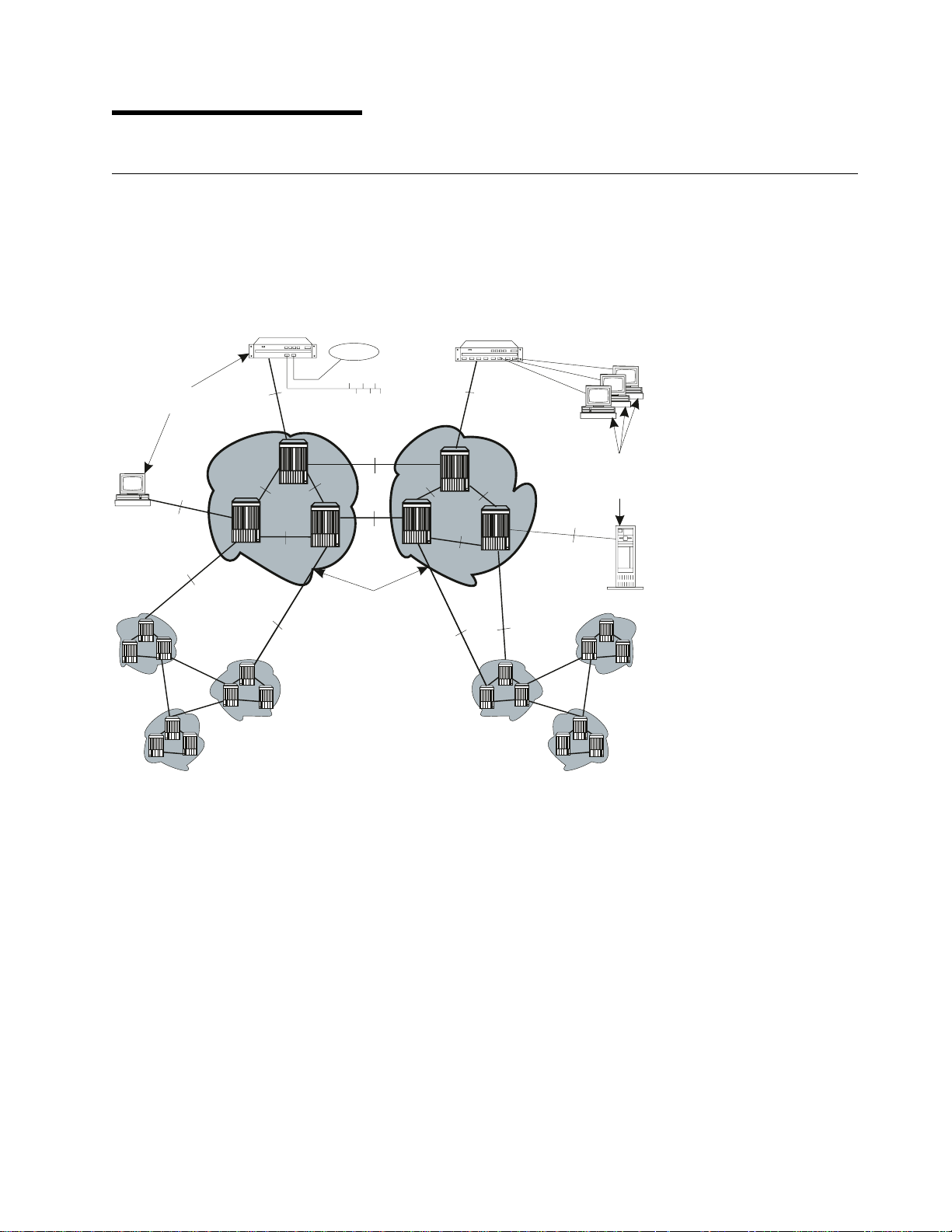
Chapter 1. Overview
ATM Networks
The purpose of an ATM network is to set up connections between ATM user devices, the two end points
of a connection.
IBM ATM subsystems can be interconnected in order to build a local, privately owned and administered
ATM network called an ATM Campus Network.
ATM
User
Devices
UNI
PNNI
PNNI
PNNI
UNI
PNNI
ATM
User
Devices
UNI
IISP
PNNI
IISP
Figure 1. Components of an ATM Campus Network
PNNI
ATM Peer groups
IISP
PNNI
UNI
IISP
Copyright IBM Corp. 1994, 1998 3
Page 20

Network Components
The terms used to describe the components of an ATM Campus Network are defined here:
ATM Campus Network
One or more interconnected ATM peer groups.
This set of peer groups is controlled by one administrative domain and a single
private owner using one network access protocol (UNI).
ATM Peer Group One or more ATM switches interconnected by PNNI interfaces, and sharing the
same peer group identifier.
ATM User Device An end system that encapsulates data into ATM cells and forwards them to the
ATM subsystem across a UNI interface. Examples of ATM user devices are:
Servers and workstations equipped with ATM adapters
ATM concentrators or workstations equipped with ATM adapters
Routers with ATM adapters
LAN ATM bridges.
The Control Point passes the network prefix of an ATM address to attached end
systems using the Interim Local Management Interface (ILMI) protocol.
Network Interfaces
The following protocols are defined in ATM standards for use across the interfaces connecting the
components of an ATM campus network:
UNI Defines the interface between an ATM user device (such as a terminal, router, bridge, server,
workstation, or concentrator equipped with an ATM adapter) and the ATM network. The ATM
subsystem supports the Private UNI as defined by the ATM Forum UNI Specifications V3.0,
V3.1 and V4.0, as well as UNI for Public carriers.
IISP Defines the interface between two ATM switches belonging to different ATM routing domains.
In the current release, IISP switches are used to interconnect PNNI peer groups.
Operator intervention is required in order to define the addresses reachable over IISP links.
You can define multiple IISP connections between two different peer groups.
PNNI Defines the interface between ATM switches in the same peer group.
The PNNI interface supports networking functions without the need of operator intervention,
such as routing, node failure and node recovery, backup, and topology management.
You can define multiple PNNI connections between two ATM switches.
VOID Defines an interface between an ATM switch and a Wide Area Network (WAN) that is used to
carry a Virtual Path Connection (VPC). ILMI is not supported on VOID ports, however when a
VP tunnel is defined, signalling is supported through the VP.
AUTO The interface is automatically set according to that of the incoming signal, as detected by ILMI.
4 IBM 8265: User's Guide
Page 21

Switched Virtual Connections (SVCs)
The IBM 8265 supports Switched Virtual Connections (SVCs), both Virtual Paths (VPs) and Virtual
Channels (VCs). SVCs can use either Reserved Bandwidth (CBR and VBR) or Best Effort (ABR and UBR)
routing.
Permanent Virtual Connections (PVCs)
The IBM 8265 supports Permanent Virtual Connections (PVCs), both Virtual Paths (VPs) and Virtual
Channels (VCs). Point-to-Point PVCs can be configured for Reserved Bandwidth (CBR and VBR) or Best
Effort (ABR and UBR) routing. Point-to-Multipoint PVCs can be configured for Reserved Bandwidth (CBR
and VBR) or Best Effort (UBR only) routing.
Virtual Path Connections (VPCs)
The IBM 8265 supports Virtual Path Connections (VPCs) as a means of extending ATM connectivity
across standard WAN connections. Each VPC can be of UNI, IISP, or PNNI type. The physical connection
to the WAN is made across a VOID or Public UNI interface.
PNNI
The IBM 8265 supports a multi-level PNNI hierarchy using a best-match algorithm for Summary
Addresses. Peer Group Identifiers may be derived from the NSAP prefix or may be defined explicitly.
IBM's PNNI routing supports:
CBR, rtVBR, and nrtVBR Reserved Bandwidth routing with shortest-path path selection
ABR Best Effort routing with precomputed or on-demand path selection
UBR Best Effort routing with widest-path or shortest-path path selection.
Chapter 1. Overview 5
Page 22

Keeping Control Point Code Up-to-Date
New versions of code for upgrading 8265 CPSW and media modules that are already in operation are
available via the Internet, at the following URL:
http://www.networking.ibm.com/8265/8265fix.html
This is the '8265 Microcode Upgrades' home page. From here, you can select the code for the appropriate
8265 module.
Automatic Notification of Updates
To automatically receive notification when microcode updates are available, register your e-mail address at
the following URL:
http://www.networking.ibm.com/8265/8265reg.html
6 IBM 8265: User's Guide
Page 23

Chapter 2. Configuring the IBM 8265
Before You Start
This chapter describes procedures for configuring your IBM 8265. Before beginning these procedures, be
sure you have:
1. Installed the ATM Workgroup Switch and attached a local configuration console, as described in the
IBM 8265 Installation Guide
2. Installed your ATM media modules, as described in the
For information on:
Using special console keyboard functions
Viewing command-line help
Entering ATM commands
see the
Configuration Procedures
Procedures in this chapter correspond to the three main parts of this manual. To configure the 8265,
follow the procedures described in each of the following sections:
“Preparing the Switch for Operation” on page 8
“Configuring Network Connections” on page 9
“Managing the Switch Hardware” on page 10.
IBM 8265 Command Reference Guide
Screen Samples
The example screen displays shown in this book are correct at the time of publication of this guide.
Actual displays may vary due to improvements in code or configuration options.
.
IBM 8265 Media Module Reference Guide
.
Copyright IBM Corp. 1994, 1998 7
Page 24

Preparing the Switch for Operation
To configure the ATM Workgroup Switch in preparation for connecting it to a network:
1.
Logon
to the 8265 as Administrator, as described in “Logging On to the 8265 ATM Switch.”
2. Configure the
page 13.
Note: It is recommended to perform the initial configuration of the basic switch settings using a
local configuration console, before connecting the 8265 to the network.
3. If you will be accessing the 8265 Control Point using Classical IP Over ATM, configure the
settings
Note: Configuring the 8265 over a TELNET connection can only occur after the IP settings have
4. If you will be accessing the 8265 Control Point using LAN Emulation Over ATM, configure the
LANE settings
5. If you will be using an SNMP application to manage the 8265 Control Point, configure the
settings as described in Chapter 6, “Configuring SNMP and Web Server Parameters” on page 35.
as described in Chapter 4, “Configuring TCP/IP Settings” on page 27.
been configured.
basic switch settings
as described in Chapter 5, “Configuring LAN Emulation Settings” on page 29.
as described in Chapter 3, “Configuring Basic Parameters” on
Logging On to the 8265 ATM Switch
When the configuration console is properly connected to the 8265, the screen below is displayed:
à ð
ATM Control Point Switch Telnet server at address 9.999.99.999
Press Enter
IP
SNMP
To log on to the switch:
1. Press Enter. The following prompt is displayed:
à ð
8265 ATM Control Point and Switch Module
(C) Copyright IBM Corp. 1997, 1998. All rights reserved.
Password:
2. Enter the Administrator password and press Enter. (The factory default Administrator password is
8265.)
Note: You have only ten seconds to enter a password when the password prompt is displayed. If you
do not enter a password, a timeout message is displayed. To re-display the password prompt
and start again, press Enter.
3. The console prompt appears, ready for receiving ATM commands:
à ð
8265ATM>
8 IBM 8265: User's Guide
Page 25

Configuring Network Connections
To configure ATM network connections from the ATM Control Point:
1. Configure the
“Working with Ports and Media Modules” on page 37.
2. To connect to switches across a WAN, configure
Chapter 9, “Linking Networks Through a WAN (VPCs)” on page 53.
3. To create PNNI peer groups, see the guidelines for configuring
as described in Chapter 11, “PNNI Networks” on page 61.
4. To define
Virtual Connections (PVCs and SVCs)” on page 63.
5. To manage and optimize
ATM Traffic” on page 67.
6. To control
Access Security” on page 77.
links
that connect the 8265 to other ATM devices, as described in Chapter 7,
PVCs
and to manage
access security
VPCs
(Virtual Path Connections), as described in
SVC
capacity, see the guidelines in Chapter 12, “Managing
ATM traffic
on the network, see the guidelines in Chapter 14, “Managing Network
on the 8265, see the guidelines in Chapter 13, “Managing
PNNI settings
(PNNI Card only)
Chapter 2. Configuring the IBM 8265 9
Page 26

Managing the Switch Hardware
To configure the ATM Workgroup Switch:
1. For general guidelines on commands used to display switch or module information, and to reset
modules or the switch, see Chapter 15, “Management Tools” on page 93.
2. To configure
the guidelines in Chapter 17, “Managing the Power Subsystem” on page 103
3. To configure the
Intelligent Cooling Subsystem” on page 113.
4. To
upload
to a Server” on page 120.
5. To
download
page 122.
6. To
update microcode
power controller module, see the guidelines in “Code Upgrades” on page 123.
power budgets
Intelligent Cooling Subsystem
switch or security settings, dumps, traces, or error logs, see the procedures in “Uploads
switch or security settings, see the procedures in “Downloads from a Server” on
or FPGA picocode on the CPSW module, any ATM media module, or a
for modules,
fault-tolerant
, see the guidelines in Chapter 18, “Managing the
operation, and
power-down
strategy, see
10 IBM 8265: User's Guide
Page 27

Part 2. Preparing the 8265 ATM Switch
Copyright IBM Corp. 1994, 1998 11
Page 28

12 IBM 8265: User's Guide
Page 29

Chapter 3. Configuring Basic Parameters
This chapter describes how to configure the ATM switch address and basic Control Point/Switch (CPSW)
module parameters.
Basic Configuration Steps
To configure the CPSW, follow the steps listed below.
1. Define the
on page 14.
2. Set the CPSW user and administrator
page 15.
3. Set the node
4. Define the switch
5. Record the service
on page 19.
6. Specify the console
7. Set the console
8. Enable the sending of
in “Alert Settings” on page 22.
9. Select the
type and volume of traffic the switch will be handling), as described in “Memory Configuration” on
page 24.
For a detailed description of each CPSW configuration command, see the
Guide
.
ATM address
clock
timeout
of the IBM 8265, as described in “Configuring the ATM Switch Address”
, as described in “Setting the Node Clock” on page 17.
name
, as described in “Switch Name” on page 18.
contact
and
prompt
, as described in “Console Prompt” on page 20.
value, as described in “Console Timeout” on page 21.
alert
messages to an SNMP workstation or the local console, as described
memory configuration
passwords
location
you want to apply to the 8265 Control Point (according to the
information, as described in “Service Contact Information”
, as described in “Setting CPSW Passwords” on
IBM 8265 Command Reference
Copyright IBM Corp. 1994, 1998 13
Page 30

Configuring the ATM Switch Address
When an 8265 is powered on for the first time, it automatically loads a default configuration, including a
default ATM address. If you have multiple switches in your network, the default ATM address must be
reconfigured so that each switch has a unique address.
The ATM address of the IBM 8265 is configured using the command SET PNNI NODE:0
ATM_ADDRESS.
Notes:
1. The PNNI commands necessary for working with the ATM address are available on both the PNNI
and the IISP code versions.
2. The following procedure describes how to set the address for the 8265 switch itself. For information on
setting up PNNI peer groups, see Chapter 11, “PNNI Networks” on page 61.
To configure the ATM address:
1. Set the address using the command SET PNNI NODE:0 ATM_ADDRESS, followed by the 20-byte
ATM address.
2. Activate the new address using the command COMMIT PNNI. This resets the ATM system.
To display the current ATM address, use the commands SHOW PNNI NODE:0, or SHOW
FUTURE_PNNI NODE:0. See Chapter 11, “PNNI Networks” on page 61 for further information on
these and related PNNI commands.
The following example sets the ATM address to
39.99.99.99.99.99.99.00.00.99.99.01.01.99.99.99.99.99.99.01.
à ð
8265ATM> set pnni node:ð atm_address: 39.99.99.99.99.99.99.ðð.ðð.99.99.ð1.ð1.99.
99.99.99.99.99.ð1
Using an ATM Host Name
To use define a
in Place of Addresses” on page 25.
host name
that can be used in place of the 8265's ATM address, see “Using Host Names
14 IBM 8265: User's Guide
Page 31

Setting CPSW Passwords
You can restrict access to switch configuration commands by defining two CPSW passwords:
The
The
See the
Administrator
(configuration) access. The factory default is 8265.
User
password, which provides access to a
commands, PING and TELNET. The factory default is a null string. If you assign the same password
for both Administrator and User, the User will have full access to all ATM commands.
IBM 8265 Command Reference Guide
password, which provides access to
subset
for more information on access to CPSW commands.
all
CPSW commands with read-write
of CPSW commands including most SHOW
Administrator Password
To define the Administrator Password:
1. Enter the command SET DEVICE PASSWORD ADMINISTRATOR and press Enter.
2. In the next three fields displayed, enter your current password and the new password (up to fifteen
characters) twice as shown below. For security purposes, the values you enter are not displayed
on the screen.
à ð
8265ATM> set device password administrator
Enter current administrator password: {old password}
New password: {new password}
Re-enter password: {new password}
Then press Enter. You are notified when your password is accepted:
à ð
Password changed.
3. To save the new password settings, use the command SAVE DEVICE or SAVE ALL.
The new administrator password will take effect the next time you log on to the CPSW.
Chapter 3. Configuring Basic Parameters 15
Page 32

User Password
1. Log on to the CPSW using the Administrator password.
2. Enter the command SET DEVICE PASSWORD USER and press Enter.
3. In the next three fields displayed, enter the administrator password and the new user password
(up to fifteen characters) twice as shown here:
à ð
8265ATM> set device password user
Enter current administrator password: {admin password}
New password: {new user password}
Re-enter password: {new user password}
Then press Enter. You are notified when the password is accepted:
à ð
Password changed.
4. To save the new password settings, use the command SAVE DEVICE or SAVE ALL.
16 IBM 8265: User's Guide
Page 33

Setting the Node Clock
You need to set the CPSW's 24-hour node clock only once, when you install the CPSW. When you set the
node clock, you establish a starting time, date, and day. To set the node clock use the SET CLOCK
command followed by the time and date parameters.
For example, the following command sets the node clock to 4:44 p.m. on September 20, 1998:
à ð
8265ATM> set clock 16:44 1998/ð9/2ð
The CPSW node clock uses its own battery and functions even when the CPSW is not operating.
Chapter 3. Configuring Basic Parameters 17
Page 34

Switch Name
To simplify the command parameters you need to enter to perform certain ATM tasks, you can assign a
unique name to each 8265. You can then use this name instead of the IP address to identify the 8265.
To set a unique name for the 8265, use the command SET DEVICE NAME followed by the name you
choose:
à ð
8265ATM> set device name helsinki
18 IBM 8265: User's Guide
Page 35

Service Contact Information
After installing the 8265 and logging on to the CPSW, you should enter the location details and the name
of the appropriate person to contact in case of a failure in the ATM subsystem or with the 8265.
To do so, enter the following commands:
1. SET DEVICE LOCATION to specify where the 8265 is installed
2. SET DEVICE CONTACT to specify the name of the service personnel to contact.
à ð
8265ATM> set device location
Enter text:
Building M4, ground floor, patch panel 1, hub number 4
8265ATM> set device contact
Enter text:
Network Manager, IBM Engineering Support, tel: 692-4444
8265ATM>
Chapter 3. Configuring Basic Parameters 19
Page 36

Console Prompt
It is recommended that you customize the prompt for each CPSW. This will help you recognize the CPSW
to which you are connected when you are logged on from a remote console.
The default prompt is:
à ð
8265ATM>
Suggestion: To make it easier to recognize the CPSW by its command prompt, set the prompt to the
name of the CPSW used in the SET DEVICE NAME command.
To customize the CPSW prompt, use the command SET TERMINAL PROMPT:
à ð
8265ATM>set terminal prompt ATM2>
ATM2>
20 IBM 8265: User's Guide
Page 37

Console Timeout
The TERMINAL TIMEOUT parameter is a safety precaution that lets you specify how long you can remain
logged on to the configuration console without entering any data from the keyboard. This prevents
unauthorized users from accessing the CPSW if you forget to log off the system. If no keystroke is entered
for the time period specified by SET TERMINAL TIMEOUT, the system automatically logs you off.
The default value for SET TERMINAL TIMEOUT is ð. This means that no timeout period is set and that
you cannot be automatically logged off from the system.
To specify a timeout value (in minutes), use the SET TERMINAL TIMEOUT command.
à ð
8265ATM>set terminal timeout 2
Chapter 3. Configuring Basic Parameters 21
Page 38

Alert Settings
You can configure the CPSW to issue alert messages when certain system events are detected. These
alerts can be trapped to an SNMP workstation, displayed on the configuration console, or both. There are
three types of alerts:
Hello
Authentication
Change.
Alerts are configured via the SET ALERT command. You can specify whether or not each type of alert is
to be trapped and sent to the trap receiver (using the TRAP parameter), and/or displayed at the local
configuration console (using the DISPLAY parameter).
By default, all alerts are set to NOTRAP and NODISPLAY. To display the current alert settings, use the
SHOW ALERT command.
Hello Alerts
A
Hello
alert is sent when:
The ATM subsytem is reset in one of the following ways:
– Pressing the ATM Reset button
– Entering the RESET command
– Powering off and powering on the 8265.
A LAN Emulation Client becomes active.
Any of the following parameters are changed:
– An agent's IP address (using the SET DEVICE IP_ADDRESS or SET DEVICE
LAN_EMULATION_CLIENT command)
– An agent's subnetwork mask (using the SET DEVICE IP_ADDRESS or SET DEVICE
LAN_EMULATION_CLIENT command)
– The ATM address of the ARP server (using the SET DEVICE ARP_SERVER command)
– The IP address of the default gateway (using the SET DEVICE DEFAULT_GATEWAY command)
– The memory configuration (using the SET DEVICE CONFIG_FUNCTIONS command).
A Hello alert is sent once a minute until an SNMP request is received. After 4 hours and 15 minutes, if no
request is received, it then shuts off and no Hello alert is sent for 6 hours. After 6 hours have elapsed,
Hello alerts are sent again for up to 4 hours and 15 minutes.
The following example directs Hello alerst to the trap receiver and the local configuration console:
à ð
8265ATM> set alert hello trap display
Alert set
22 IBM 8265: User's Guide
Page 39

Authentication Alerts
An
Authentication
community name is not valid for the attempted read or write operation.
The following example sends Authentication alerts to the local configuration console only:
à ð
8265ATM> set alert authentication notrap display
Alert set
alert is sent when an unauthorized user tries to access the 8265 and the IP address or
Change Alerts
A
Change
An ATM media module is isolated or reconnected
An ATM media module port is enabled or disabled
Time and date used on the ATM subsystem are reconfigured
Name, location, or service contact information for the CPSW module are reset.
alert is sent when any of the following changes are made:
The following example sends Change alerts to the trap receiver only:
à ð
8265ATM> set alert change trap nodisplay
Alert set
Chapter 3. Configuring Basic Parameters 23
Page 40

Memory Configuration
Depending on the type of CPSW module, the amount of memory installed, and the type and volume of
traffic the switch will be handling, select from among the predefined memory configurations available.
1. Check to see which memory configurations are available using the SET DEVICE
CONFIG_FUNCTIONS command:
à ð
8265ATM> set device config_functions help
Here are possible values :
number ! Name ! Comments
------------------------------------------------------------------------------Config 1 ! 32_P_P ! P2P
Config 2 ! 32_P_M ! Mixed
Current Memory Profile is 32_P_M.
8265ATM>
2. To see the details for a selected memory type enter help after selecting one of the available
configurations:
à ð
8265ATM> set device config_functions config_1 help
Configuration 1 is: 32_P_P
P2P
Number of VPCs : 512
Number of trees : 1ð
Number of branches : 32ððð
Number of parties : 1ðð
Number of PVCs : 512
Number of reachable addresses : 64
Number of dynamic addresses : 512
Number of E164 addresses : 6ð
LES : Disabled
8265ATM>
3. Select the memory configuration you want.
à ð
8265ATM> set device config_functions config_1
Configuration 1 is: 32_P_P
P2P
Number of VPCs : 512
Number of trees : 1ð
Number of branches : 32ððð
Number of parties : 1ðð
Number of PVCs : 512
Number of reachable addresses : 64
Number of dynamic addresses : 512
Number of E164 addresses : 6ð
LES : Disabled
Accepting this configuration will reset the ATM subsystem.
Are you sure ? (Y/N)
Note: Activating a LAN Emulation Server (LES) affects the memory configuration currently in use.
24 IBM 8265: User's Guide
Page 41

Using Host Names in Place of Addresses
You can define a host name to be used in place of any ATM or IP address using the SET HOST
command. This allows you to assign a meaningful, easy to remember name to devices on the network.
Note: Host names are not case-sensitive – for example,
For example, an 8265 located in Laboratory C with an ATM address of
39.99.99.99.99.99.99.00.00.99.99.01.01.99.99.99.99.55.86.01 could be called LabC. This can be set using
the SET HOST command as shown in the following example:
à ð
8265ATM>set host LabC atm 39.99.99.99.99.99.99.ðð.ðð.99.99.ð1.ð1.99.99.99.99.55.
86.ð1
An 8265 located in the Development Department with an IP address of 9.100.109.203 could be called
DevelA. This can be set using the SET HOST command as shown in the following example:
à ð
8265ATM>set host DevelA ip 9.1ðð.1ð9.2ð3
To display currently defined ATM and IP host names, use the SHOW HOST command.
LabC
and
labc
refer to the same switch.
Chapter 3. Configuring Basic Parameters 25
Page 42

26 IBM 8265: User's Guide
Page 43

Chapter 4. Configuring TCP/IP Settings
This chapter describes how to define the necessary TCP/IP settings to access the 8265 through a
Classical IP subnetwork.
TCP/IP Configuration Steps
To configure the TCP/IP settings, follow the steps listed below
1. Define the
on page 28.
2. Specify the IP address of the
3. Specify the ATM address of the
For a detailed description of each command, see the
IP address
and
subnetwork mask
default gateway
ARP server
, as described in “IP Address and Subnetwork Mask”
, as described in “Default Gateway” on page 28.
, as described in “ARP Server” on page 28.
IBM 8265 Command Reference Guide
.
Copyright IBM Corp. 1994, 1998 27
Page 44

IP Address and Subnetwork Mask
In order for SNMP to run properly, every device in the network must have a unique IP address. To set the
IP address and subnetwork mask of the CPSW, use the SET DEVICE IP_ADDRESS ATM command.
For example, the following command sets a unique IP address for a Classical IP over ATM subnetwork on
the CPSW and a subnetwork mask for an ATM class C device:
à ð
8265ATM> set device ip_address atm 195.44.45.48 FF.FF.FF.ðð
You can also assign a separate IP address to the CPSW when accessed via the Ethernet port on the front
panel of the CPSW by using the SET DEVICE IP_ADDRESS ETH command.
Using an IP Host Name
To use define a
in Place of Addresses” on page 25.
Default Gateway
The default gateway is the IP address of the gateway that will receive and forward packets whose
addresses are unknown to the ATM subnetwork. The default gateway is useful when sending CPSW alert
packets to a management workstation that is on a different network and is accessible via a router.
To specify the IP address of the default gateway, use the SET DEVICE DEFAULT_GATEWAY command:
à ð
8265ATM> set device default_gateway 195.44.45.26
ARP Server
The ARP (Address Resolution Protocol) server is used in a classical IP over ATM network to map IP
addresses to ATM addresses. This is necessary to permit communication between an ATM network and
SNMP stations in a Classical IP subnetwork.
To specify the ATM address of the ARP server, use the SET DEVICE ARP_SERVER command:
host name
that can be used in place of the 8265's ATM address, see “Using Host Names
à ð
8265ATM> set device arp_server 39.11.FF.22.99.99.99.ðð.ðð.ðð.ðð.ð1.49.11.11.11.
11.11.11.49
28 IBM 8265: User's Guide
Page 45

Chapter 5. Configuring LAN Emulation Settings
This chapter describes how to define the necessary LAN emulation (LANE) settings to access the 8265
through a LANE subnetwork.
Note: Activating a LAN Emulation Server (LES) affects the memory configuration currently in use (See
“Memory Configuration” on page 24.).
LANE Configuration Steps
To configure LANE settings, follow the steps listed below.
1. Configure the
2. Specify the access method for connecting to the
described in “LECS ATM Address” on page 31.
3. To start a
Servers (LES/BUS)” on page 33.
For a detailed description of each command, see the
Lan Emulation Client (LEC)
Lan Emulation Server (LES/BUS)
, as described in “LEC Settings” on page 30.
, follow the instructions in “Setting Up LAN Emulation
LAN Emulation Configuration Server (LECS)
IBM 8265 Command Reference Guide
.
, as
Copyright IBM Corp. 1994, 1998 29
Page 46

LEC Settings
In order for SNMP to run properly, every device in the network must have a unique IP address. In a LAN
emulation subnetwork, you must use the SET DEVICE LAN_EMULATION_CLIENT command to assign a
unique IP address and subnetwork mask to the CPSW.
To configure the LEC, use the SET DEVICE LAN_EMULATION_CLIENT command with the following
parameters:
LAN type (Ethernet or Token-Ring)
IP address
Subnetwork Mask
Individual MAC address
Associated LES ATM address
Notes:
1. You should start the LES (whether internal or external) before you configure the LEC, in order to get
its ATM address (via the SHOW LAN_EMUL SERVERS command).
2. The LEC may be Ethernet or Token-Ring. If Ethernet, then you must specify the Ethernet type (either
DIX or 802.3.) It is possible to specify one Ethernet and one Token-Ring LEC simultaneously.
3. If two LECs are configured, they must have different IP addresses, even if they are connected to
different LESs.
4. The MAC address must be in a 802.3 format. Local and universal administrated MAC addresses are
supported.
5. The associated LES ATM address is the address of a LES monitoring the emulated LAN. The LES
must be a LE Forum compliant LES, connected to an 8265 switch or 8285 ATM Workgroup Switch.
6. The maximum frame size and emulated LAN name are provided by the associated LES.
7. The SET DEVICE LAN_EMULATION_CLIENT command automatically starts the LEC.
8. No command to stop the LEC is available.
9. The first time the SET DEVICE LAN_EMULATION_CLIENT command is used, you must configure all
parameters before saving the configuration settings (no default values are provided). Once the
configuration settings have been saved, it is possible to change only one parameter at a time using
the SET DEVICE LAN_EMULATION_CLIENT command.
Example
For example, to configure an Ethernet LEC:
à ð
8265ATM> set device lan_emulation_client eth eth_type DIX ip_address 9.1ðð.2ð.55
ip_address:9.1ðð.1ð2.98 mac_address:185ð93928473 subnet_mask:ðð.44.82.56 no_lecs
_with_les:lesð24a
Client starting.
8265ATM>
After the eth parameter, the other parameters may be entered in any order.
30 IBM 8265: User's Guide
Page 47

LECS ATM Address
Some Lan Emulation Clients (LECs) determine the ATM address of their associated LES from the LAN
Emulation Configuration Server (LECS). The CPSW supports these LECs with three separate methods for
establishing a connection to the LECS:
ILMI MIB
LECS Well Known Address
Fixed PVC (0.17).
ILMI MIB
The LEC can get the unicast ATM address by doing a GETNEXT on the variable atmSrvcRegATMAddress
in the ILMI MIB.
For LECs that use this method of addressing, you must define the LECS ATM address in each ATM
switch that deals with these LECs. You define the LECS ATM address with the SET LAN_EMUL
CONFIGURATION_SERVER command.
à ð
8265ATM> set lan_emul configuration_server 39.99.99.99.99.99.99.ðð.ðð.99.99.ð1.
84.ðC.11.8ð.95.4F.13.ðð
You may define several ATM addresses. at any given time.
LECS Well Known Address
The LEC can directly call on one of two LEC Well Known Addresses, which are:
47.ðð.79.ðð.ðð.ðð.ðð.ðð.ðð.ðð.ðð.ðð.ðð.ðð.Að.3E.ðð.ðð.ð1.ðð
and
C5.ðð.79.ðð.ðð.ðð.ðð.ðð.ðð.ðð.ðð.ðð.ðð.ðð.Að.3E.ðð.ðð.ð1.ðð
Note: In order to use this method, the LEC must be able to make calls to the WKA. If the LECS does
not support calls to the WKA, you must use another addressing method.
Fixed PVC (0.17)
If the LEC requires a connection via fixed PVC, you must use the command SET PVC to define a PVC for
virtual connection on the LEC side with vpi.vci equal to 0.17. When defining a PVC for virtual channel
connection (VCC), the range of allowed VCI values includes the value 17.
The following example defines a PVC on the LEC side with vpi-vci equal to 0.17 going to the LECS side:
à ð
8265ATM> set pvc 1.2 1 this_hub_port:2.3 5 channel_point_to_point ð.17 ð.33 best
_effort
PVC set and started.
8265ATM>
Chapter 5. Configuring LAN Emulation Settings 31
Page 48

Checking the LEC Configuration
To check the configuration of the LECS ATM addresses, enter the following command:
à ð
8265ATM> show lan_emul configuration_server
Index ATM address
------------------------------------------------------------------------------ 1 39.99.99.99.99.99.99.ðð.ðð.ðð.ðð.ð1.94.ðð.82.65.82.65.ðð.ðð
2 39.99.99.99.99.99.99.ðð.ðð.ðð.ðð.ð1.94.ðð.82.65.82.62.ð2.ð2
8265ATM>
32 IBM 8265: User's Guide
Page 49

Setting Up LAN Emulation Servers (LES/BUS)
You can define either one or two separate LAN Emulation Servers (LESs). Either one, or both, may be
Token Ring or Ethernet. If you start two LESs, the maximum number of LECs (128) applies to both LESs
combined
When you start a LES, its associated BUS is automatically started.
.
Starting a LES
To start a LES, use the SET LAN_EMUL SERVER command.
For example, to start an Ethernet LES:
1. Define the LES parameters using SET LAN_EMUL SERVER and press Enter. You are prompted
for the name of the LES:
à ð
8265ATM> set lan_emul server 1 start eth 4 2 4544
Emulated LAN Name:
2. Type the name you want to assign to the LES and press Enter:
à ð
8265ATM> set lan_emul server 1 start eth 4 2 4544
Emulated LAN Name: LAN1eth
Starting server.
8265ATM>
Chapter 5. Configuring LAN Emulation Settings 33
Page 50

Displaying LES Parameters
Use the SHOW LAN_EMUL SERVERS command to display the current status and parameters defined for
both LESs:
à ð
8265ATM> show lan_emul servers
-------------------------------------------------------------------------------
--------------------------- LAN Emulation Server 1 ---------------------------Status : Running.
LAN type : Ethernet.
Actual ELAN name : "IBM_ETHERNET_LAN1".
Desired ELAN name : "".
Actual max frame size : 1516.
Desired max frame size: 1516.
ATM address : 39.99.99.99.99.99.99.ðð.ðð.99.99.ð1.5ð.5ð.5ð.5ð.5ð.5ð.5ð.ð2
LEC Id Range : 1 to 3.
Current number of operational clients : 1ð.
-------------------------------------------------------------------------------
--------------------------- LAN Emulation Server 2 ---------------------------Status : Running.
LAN type : Token Ring.
Actual ELAN name : "IBM_TOKEN_RING_LAN2".
Desired ELAN name : "".
Actual max frame size : 4544.
Desired max frame size: 4544.
ATM address : 39.99.99.99.99.99.99.ðð.ðð.99.99.ð1.5ð.5ð.5ð.5ð.5ð.5ð.5ð.ð3
LEC Id Range : 4 to 6.
Current number of operational clients : 4.
8265ATM>
Stopping a LES
Use the STOP parameter on the SET LAN_EMUL SERVER command to stop a LES.
For example to stop emulated LAN number 2:
à ð
8265ATM> set lan_emul server 2 stop
Stopping a LES also stops its associated BUS.
Depending on the number of LECs that are connected to the LES, there may be a delay from the time the
command is issued to the time the LES is completely stopped. For this reason, you should verify that the
LES has stopped using the SHOW LAN_EMUL SERVERS command before trying to start the LES again.
LEC Access Control
The LECs connected to an LES must have their Emulated LAN Name set equal to that of the LES, if it is
specified. LECs with a non-empty name that is different from that of the LES will be rejected.
34 IBM 8265: User's Guide
Page 51

Chapter 6. Configuring SNMP and Web Server Parameters
Carry out the procedures in this section only if you want to manage your ATM subsystem from an
SNMP workstation or from a web browser attached to the network.
SNMP Access Requirements
If you want to manage the ATM subsystem from an SNMP workstation, you may access the 8265 through
either a Classical IP subnetwork or a LAN Emulation subnetwork.
The steps required to set the SNMP parameters depend on the type of subnetwork you will use:
Classical IP over ATM subnetwork (IP)
1. Define the
Subnetwork Mask” on page 28.
2. Specify the IP address of the
page 28.
3. Specify the ATM address of the
4. Enable the sending of
5. Define the
LAN Emulation over ATM subnetwork (LE)
1. Configure the
2. Specify the IP address of the
page 28.
3. Enable the sending of
4. Define the
Note: Although it is expensive, nothing prevents you from using both subnetworks at the same time,
each subnetwork being independent from the other (no communication between them). In the latter
case an ARP server and an 802.3 LES are required. A single subnetwork must be chosen for the
Default Gateway.
IP address
community table
Lan Emulation Client (LEC)
community table
and
subnetwork mask
default gateway
ARP server
alert messages
as described in “Community Table” on page 36.
default gateway
alert messages
as described in “Community Table” on page 36.
, as described in “IP Address and
, as described in “Default Gateway” on
, as described in “ARP Server” on page 28.
, as described in “Alert Settings” on page 22.
, as described in “LEC Settings” on page 30.
, as described in “Default Gateway” on
, as described in “Alert Settings” on page 22.
Web Access Requirements
To access the 8265 Control Point integrated web server from a web browser attached to the network:
1. Define the
on page 28.
2. Add an entry to the
web server. See “Community Table” on page 36.
Copyright IBM Corp. 1994, 1998 35
IP address
community table
and
subnetwork mask
, as described in “IP Address and Subnetwork Mask”
for each IP address from which you will access the integrated
Page 52

Community Table
SNMP Access
The Community table defines which SNMP stations in the network can access information from the
CPSW, and which station(s) will receive a trap from the CPSW when an error is detected.
To create an entry in the Community table, use the SET COMMUNITY command. For example, the
following command specifies that a community name called ATMMGMT with an IP address of 195.44.45.244
has read-write access to the CPSW:
à ð
8265ATM> set community ATMMGMT 195.44.45.244 read_write
The community name parameter is
uppercase or lowercase letters exactly as you want it to appear. To display a list of existing community
names, use the SHOW COMMUNITY command.
case-sensitive
. Be sure, therefore, to enter the community name in
Web Access
The Community table also defines which IP addresses can access the integrated web server on the 8265
Control Point.
To create a web-access entry in the Community table, use the SET COMMUNITY command. For
example, the following command specifies that a community name called webmgr with an IP address of
195.44.22.544 can access the integrated web server:
à ð
8265ATM> set community webmgr 195.44.22.544 http_enable
Remember that the community name parameter is
case-sensitive
.
36 IBM 8265: User's Guide
Page 53

Chapter 7. Working with Ports and Media Modules
This chapter describes:
How to connect and disconnect a module from the network
How to enable ports and interfaces.
How to display module and port information.
Connecting Modules to the Network
Before the ports on a module can be enabled for operation, the module must be connected to the network.
To connect the module in slot 5 to the network:
à ð
8265ATM> set module 5 connected
When you connect a module to the network, you may also enable or disable all the ports on the module
together, at the same time:
à ð
8265ATM> set module 5 connected enable
Copyright IBM Corp. 1994, 1998 37
Page 54

Enabling ATM Ports
Before you can use the devices attached to media module ports, you must enable each port and configure
the type of interface used by the port to receive and transmit ATM data. For example, to enable port 2 of a
module in slot 1 as a UNI port:
à ð
8265ATM> set port 1.2 enable uni
Note that you can specify multiple ports on the same module within the same command, for example set
port 1.2 3 5 4 7 enable uni would enable ports 2, 3, 4, 5, and 7.
You can set a port to any of the ATM interfaces:
User-to-Network (UNI)
Interim Inter-Switch Signalling (IISP)
Private Network-to-Network (PNNI)
VOID
AUTO.
8260 Modules on the 8265
The number of PNNI ports that can be enabled on 8260 modules is restricted. The sum total
bandwidth of the ports cannot exceed 212 Mbps. For example
If you have a 4-port 100 Mbps module, you can only enable two of the ports (200 Mbps
bandwidth).
If you have a 12-port 25 Mbps module, you can enable up to 8 of the ports (200 Mbps bandwidth).
If you have a 3-port 155 Mbps module, you can only enable one of the ports. (155 Mbps
bandwidth).
38 IBM 8265: User's Guide
Page 55

Displaying Module and Port Settings
Module Settings
Enter the SHOW MODULE command to display information for a module installed in a specified slot, or to
display information for all modules and submodules installed in the 8265.
Example – SHOW MODULE: In the following example, the SHOW MODULE command displays
basic information for a controller module installed in slot 18.
à ð
8265ATM> show module 18
Slot Install Connect Operation General Information
---------------------------------------------------------------18 Y N Y Active Controller Module
8265ATM>
Example – SHOW MODULE VERBOSE: In the following example, SHOW MODULE VERBOSE
displays detailed information for a 4-port 155 Mbps module installed in slot 1:
à ð
8265ATM> show module 1 verbose
Slot Install Connect Operation General Information
---- ------- ------- --------- ---------------------------1 Y Y Y 8265 ATM 4-ports 155 Mbps Module
status: connected / hardware OK
P/N: 58G9878 EC level: D55931 Manufacture: VIME
Operational FPGA version : 6
Type Mode Status
------------------------------------------------------------------------
1.ð1:PNNI enabled UP
1.ð2:VOID enabled no activity
1.ð3:UNI enabled UP
1.ð4:UNI disabled
8265ATM>
enable / normal
Backup FPGA version : 6
Chapter 7. Working with Ports and Media Modules 39
Page 56

Example – SHOW MODULE ALL: In this example, SHOW MODULE ALL displays the following
information for all installed modules:
Slot location
Module name
Module version number
Network assignment
General information.
à ð
8265ATM> show module all
Slot Install Connect Operation General Information
-------------------------------------------------------------------------------1 Y n n 8265 ATM WAN 2 Module
2n n n3n n n4 Y Y Y 8265 ATM 4-ports 155 Mbps Module
5n n n6n n n7n n n8n n n9 Y Y Y 8265 ATM Control Point and Switch Module:Active
1ð Y n n <extension>
11 n n n 12 n n n 13 Y n n 8265 ATM 622 Mbps Module
14 Y n n 8265 ATM 4-ports 155 Mbps Module
15 Y n n 8265 ATM 622 Mbps Module
16 n n n 17 n n n 18 Y n Y Active Controller Module
19 n n n -
8265ATM>
á
ñ
40 IBM 8265: User's Guide
Page 57

Port Settings
Enter the SHOW PORT command to display information for one or more ports on the 8265.
Example – SHOW PORT ALL
à ð
8265ATM> show port all
Type Mode Status
-------------------------------------------------------------------------------
1.ð1: UNI enabled no activity
1.ð2:PNNI enabled no activity
1.ð3: UNI enabled UP
1.ð4: UNI enabled UP
Type Mode Status
------------------------------------------------------------------------------
3.ð1:UNI disabled
3.ð2:UNI disabled
3.ð3:PNNI enabled no activity
8265ATM>
The following information is displayed about each port:
Port Number of the port on the CPSW.
Type Type of ATM interface used (UNI, IISP, PNNI).
Mode Whether the port has been enabled or disabled using the SET PORT command.
Status Operational status of the port.
The following statuses are displayed during normal port operation:
DOWN: Establishing *
DOWN: Configuring *
DOWN: Retrieving *
UP: Registering *
UP
If any other port status is displayed, or if any of the transient statuses (marked with * in the list)
are displayed continuously, see the “Problem Determination” section in the
Module Reference Guide
.
IBM 8265 Media
Chapter 7. Working with Ports and Media Modules 41
Page 58

Example – SHOW PORT VERBOSE
à ð
8265ATM> show port 8.1 verbose
Type Mode Status
-------------------------------------------------------------------------------
8.ð1: UNI disabled
UNI Type : Private
Signalling Version : Auto
ILMI status : DOWN:Not in service
ILMI vci : ð.16
RB Bandwidth : unlimited
Police admin. : on
Signalling vci : ð.5
RB Admin weight : 5ð4ð
NRB Admin weight : 5ð4ð
VPI range admin. : ð-15 (4 bits)
VCI range admin. : ð-1ð23 (1ð bits)
VPI range oper. : ð-15 (4 bits)
VCI range oper. : ð-1ð23 (1ð bits)
Connector : SC DUPLEX
Media : multimode fiber
Port speed : 155ððð kbps
Connection shaping : Off.
Remote device is active
Frame format : SONET STS-3c
Scrambling mode : frame and cell
Clock mode : internal
Signal Detect : active
RDOOL Status : inactive
Loss Of Signal : inactive
Loss Of Frame : inactive
Line FERF : inactive
Line AIS : inactive
Path FERF : inactive
Path AIS : inactive
Loss Of Pointer : inactive
Loss Cell Delineation : inactive
Out Of Frame : inactive
B1 Errors Counter : ð
HCS Errors Counter : ð
8265ATM>
The Information displayed depends on the settings available for the port type.
42 IBM 8265: User's Guide
Page 59

Part 3. Configuring ATM Network Connections
Copyright IBM Corp. 1994, 1998 43
Page 60

44 IBM 8265: User's Guide
Page 61

Chapter 8. Linking to ATM Devices
This chapter discusses the basic procedures for linking ATM ports on the 8265 ATM Switch directly to:
ATM User Devices
Non-PNNI ATM Switches
PNNI ATM Switches
To link the 8265 to another ATM switch across a WAN, see the procedures in Chapter 9, “Linking
Networks Through a WAN (VPCs)” on page 53.
Linking to ATM User Devices (UNI)
UNI
Figure 2. UNI Link to a User Device
To link one port on the 8265 directly to an ATM User Device (such as a Server or LAN ATM Bridge):
1. Connect the port's module to the network using the SET MODULE command.
2. Enable the port as UNI using the SET PORT command, defining any traffic management settings
that are needed.
à ð
8265ATM> set module 7 connected
Slot 7:Module set.
8265ATM> set port 7.1 enable uni bandwidth_rb:1ðð
7.ð1:Port set
8265ATM>
3. If the device does not support ILMI address registration, use SET REACHABLE ADDRESS to
define the reachable address prefix necessary to reach the device. (See “Defining Reachable
Addresses” on page 51 for further information.)
Lan Switch
Emulated
Ethernet Stations
à ð
8265ATM> set reachable address 5.2 96 39.99.99.99.99.99.99.ðð.ðð.99.99.ð8
Entry set.
8265ATM>
If several reachable addresses on a PNNI switch share the same network prefix, they should be
entered as a PNNI summary address to reduce routing overhead. See Chapter 11, “PNNI
Networks” on page 61 for details on configuring summary addresses.
For guidelines on configuring traffic management settings, see Chapter 13, “Managing ATM Traffic” on
page 67.
Copyright IBM Corp. 1994, 1998 45
Page 62

Linking PNNI Switches in the Same Peer Group (PNNI)
Peer Group A
Local
PNNI
PNNI
Figure 3. PNNI Link to a PNNI Switch
(Requires the PNNI Code Card.)
To link one port on the 8265 directly to an ATM switch that supports PNNI routing:
1. On the local switch, connect the port's module to the network using the SET MODULE command.
2. On the local switch, enable the port as PNNI using the SET PORT command, defining any traffic
management settings that are needed.
à ð
LOCAL> set module 4 connected
Slot 4:Module set.
LOCAL> set port 4.2 enable PNNI
4.ð2:Port set
LOCAL>
Remote
PNNI
3. On the remote switch, connect the port's module to the network using the SET MODULE
command.
4. On the remote switch, enable the port as PNNI using the SET PORT command, defining any
traffic management settings that are needed.
à ð
REMOTE> set module 8 connected
Slot 8:Module set.
REMOTE> set port 8.4 enable PNNI
8.ð4:Port set
REMOTE>
For guidelines on configuring traffic management settings, see Chapter 13, “Managing ATM Traffic” on
page 67.
46 IBM 8265: User's Guide
Page 63

Linking Non-PNNI ATM Switches (IISP)
Local
Remote
IISP
IISP
Figure 4. IISP Link to Non-PNNI Switch
IISP
When linking to another ATM switch using IISP, one switch must be defined as "NETWORK" and the
other switch defined as "USER".
To link one port on the 8265 directly to an ATM switch that does not support PNNI routing:
1. On the local switch, connect the port's module to the network using the SET MODULE command.
2. On the local switch, enable the port as IISP using the SET PORT command, defining any traffic
management settings that are needed.
à ð
LOCAL> set module 5 connected
Slot 5:Module set.
LOCAL> set port 5.2 enable IISP network bandwidth_rb:125
5.ð2:Port set
LOCAL>
3. On the local switch, use SET REACHABLE ADDRESS to define the reachable address prefix of
the remote switch, and of any devices attached to the remote switch that do not support ILMI
registration. (See “Defining Reachable Addresses” on page 51 for further information.)
à ð
LOCAL> set reachable address 5.2 96 39.99.99.99.99.99.99.ðð.ðð.99.99.1ð
Entry set.
LOCAL>
Note: Do not specify a VPI when defining a reachable address on an IISP link.
4. On the remote switch, connect the port's module to the network using the SET MODULE
command.
5. On the remote switch, enable the port as IISP using the SET PORT command, defining any traffic
management settings that are needed.
à ð
REMOTE> set module 3 connected
Slot 3:Module set.
REMOTE> set port 3.1 enable IISP user bandwidth_rb:125
3.ð1:Port set
REMOTE>
Chapter 8. Linking to ATM Devices 47
Page 64

6. On the remote switch, use SET REACHABLE ADDRESS to define the reachable address prefix of
the local switch, and of any devices attached to the local switch that do not support ILMI
registration.
à ð
REMOTE> set reachable address 5.2 96 39.99.99.99.99.99.99.ðð.ðð.99.99.ð8
Entry set.
REMOTE>
For guidelines on configuring traffic management settings, see Chapter 13, “Managing ATM Traffic” on
page 67.
48 IBM 8265: User's Guide
Page 65

Linking PNNI Switches in Different Peer Groups (IISP)
Peer Group A Peer Group B
Local
Remote
IISP
PNNI
Figure 5. IISP Link to PNNI Switch in Different Peer Group
PNNI
(Requires the PNNI Code Card.)
When linking to a PNNI switch in another peer group, you use IISP, and one switch must be defined as
"NETWORK" and the other switch defined as "USER".
To link one port on the 8265 to an ATM switch in another peer group:
1. On the local switch, connect the port's module to the network using the SET MODULE command.
2. On the local switch, enable the port as IISP using the SET PORT command, defining any traffic
management settings that are needed.
à ð
LOCAL> set module 5 connected
Slot 5:Module set.
LOCAL> set port 5.2 enable IISP network bandwidth_rb:125
5.ð2:Port set
LOCAL>
3. On the local switch, use SET REACHABLE ADDRESS to define the reachable address prefix of
the remote switch, and of any devices attached to the remote switch that do not support ILMI
registration. (See “Defining Reachable Addresses” on page 51 for further information.)
à ð
LOCAL> set reachable address 5.2 96 39.99.99.99.99.99.99.ðð.ðð.99.99.1ð
Entry set.
LOCAL>
Note: Do not specify a VPI when defining a reachable address on an IISP link.
4. On the remote switch, connect the port's module to the network using the SET MODULE
command.
5. On the remote switch, enable the port as IISP using the SET PORT command, defining any traffic
management settings that are needed.
à ð
REMOTE> set module 3 connected
Slot 3:Module set.
REMOTE> set port 3.1 enable IISP user bandwidth_rb:125
3.ð1:Port set
REMOTE>
Chapter 8. Linking to ATM Devices 49
Page 66

6. On the remote switch, use SET REACHABLE ADDRESS to define the reachable address prefix of
the local switch, and of any devices attached to the local switch that do not support ILMI
registration.
à ð
REMOTE> set reachable address 5.2 96 39.99.99.99.99.99.99.ðð.ðð.99.99.ð8
Entry set.
REMOTE>
For guidelines on configuring traffic management settings, see Chapter 13, “Managing ATM Traffic” on
page 67.
50 IBM 8265: User's Guide
Page 67

Defining Reachable Addresses
The PNNI protocol automatically determines routing information for all devices in a PNNI hierarchical peer
group. In those circumstances where PNNI cannot automatically determine this information, you must
provide it manually, by defining entries in the table of Reachable Addresses.
For User Devices
When a user device that does not support ILMI address registration is linked to an ATM network (over a
UNI link), you must define a reachable address entry at the UNI link that encompasses the ATM address
of the user device.
For IISP Switches
When linking two ATM switches that do not support PNNI (for example, an 8265 running on the IISP code
card), you must define reachable address entries that encompass all ATM addresses to be reached
through the IISP link.
For PNNI Switches Reachable Over IISP Links
When linking to another PNNI peer group over an IISP link, you must define reachable address entries at
the IISP link that encompass all ATM addresses to be reached in the other peer group.
For Non-Hierarchical PNNI Switches
Linking a hierarchical PNNI peer group to a non-hierarchical peer group requires special consideration
when defining reachable address entries.
Scope of the Reachable Address
To limit the distribution of the reachable address to a a specified PNNI level (or
organizational/administrative scope), use the SCOPE parameter on the SET REACHABLE ADDRESS
command.
Organizational levels correspond to PNNI routing levels as follows:
Scope Level Scope Level
1-3 96 11-12 48
4-5 80 13-14 32
6-7 72 15 0
8-10 64
Chapter 8. Linking to ATM Devices 51
Page 68

52 IBM 8265: User's Guide
Page 69

Chapter 9. Linking Networks Through a WAN (VPCs)
Guidelines for VPCs
Virtual Path Connections (VPCs), also known as VP tunneling, allow ATM switches to connect to each
other across Wide Area Network (WAN) links. When an 8265 is physically attached to a WAN, and a VPC
is established across the WAN link, the device attached at the other side of the WAN appears to the local
switch as if it were an adjacent device. A VPC extends the connectivity of the 8265 and can provide
multiple VP tunnels across the same physical WAN link.
VPCs are created using the SET VPC_LINK command, and may only be created on VOID ports. Each
VPC can be of UNI, IISP, PNNI, or AUTO type, and is functionally equivalent to the corresponding
physical link. This means that ILMI, signalling, and routing may be defined separately on each VPC.
Figure 6 shows various possible VPC configurations.
Peer Group A
VOID Link
VOID Link
PNNI
C
VP
I
UN
Lan Switch
Emulated
Ethernet Stations
Figure 6. UNI, IISP, and PNNI VPC Links
WAN
PNNI
PNNI
VOID Link
Peer Group B
Note: The maximum permissible number of VPCs depends on the memory configuration currently in use
(See “Memory Configuration” on page 24.)
Copyright IBM Corp. 1994, 1998 53
Page 70

Example: Linking PNNI Switches Across a WAN (PNNI VPC)
(Requires the PNNI Code Card.)
To link the 8265 across a WAN to a another switch that supports PNNI routing:
1. On the local switch, connect the port's module to the network using the SET MODULE command.
2. On the local switch, enable the port as VOID using the SET PORT command, defining any traffic
management settings that are needed.
à ð
LOCAL> set module 4 connected
Slot 4:Module set.
LOCAL> set port 4.2 enable VOID
4.ð2:Port set
LOCAL>
3. On the local switch, define a VPC on the VOID port.
à ð
LOCAL> set vpc_link 4.2 15 enable PNNI bandwidth: 13ð
Accepted
LOCAL>
4. On the remote switch, connect the port's module to the network using the SET MODULE
command.
5. On the remote switch, enable the port as VOID using the SET PORT command, defining any
traffic management settings that are needed.
à ð
REMOTE> set module 8 connected
Slot 8:Module set.
REMOTE> set port 8.4 enable PNNI
8.ð4:Port set
REMOTE>
6. On the remote switch, define the same VPC on the VOID port.
à ð
REMOTE> set vpc_link 8.4 15 enable PNNI bandwidth: 13ð
Accepted
REMOTE>
For guidelines on configuring traffic management settings, see Chapter 13, “Managing ATM Traffic” on
page 67.
54 IBM 8265: User's Guide
Page 71

VPC Traffic Shaping
VPC Traffic Shaping regulates traffic out to a lower rate than the line speed. Control at the VPC level
means that the switch can have different shaping values for different VPCs that are active on the same
port.
Note: VPC Traffic shaping not available on 8260 modules.
To define traffic shaping on a VPC, use the SET VPC_LINK command:
1. Define the total bandwidth of the VPC using the BANDWIDTH: parameter (mandatory).
2. Set the SHAPING: parameter to ON to enable traffic shaping.
3. Specify the traffic type on the VPC using the TUNNELED_SERVICE_CATEGORY: parameter:
CBR VBR only
ABR only
UBR only
CBR VBR, and ABR
CBR VBR, and UBR
ABR and UBR
CBR VBR, ABR, and UBR.
à ð
8265ATM> set vpc_link 5.1 3 enable uni bandwidth:5ðð shaping:on tunneled_servi
ce_category:cbr_vbr_only
Accepted
8265ATM>
Chapter 9. Linking Networks Through a WAN (VPCs) 55
Page 72

Reachable Addresses and VPC Links
When a VPC link connects to devices that do not support ILMI address registration, you must also define
reachable address prefixes for those devices using the SET REACHABLE_ADDRESS command.
If you define a VPC link of type IISP, check that the VPI of the VPC link is also defined in your reachable
address.
If several reachable addresses share the same network prefix in a PNNI network, they should be entered
as a PNNI summary address to reduce routing overhead. See Chapter 11, “PNNI Networks” on page 61
for details on configuring summary addresses.
See “Defining Reachable Addresses” on page 51 for more information on defining reachable addresses.
Shifting the Range of VPI Values
To create a new range of VPI values on a VOID port, you can specify a number to be added to the default
VPI values, using the VPI_OFFSET: parameter of the SET PORT command.
For example, with VPI_VCI set to 6.8, the default range of values is 0-63. To shift the range to 192-255,
use VPI_OFFSET:192.
Notes:
1. All VPCs must be defined with VPI values that are within the new range.
2. SVCs will be allocated using the smallest value in the VPI range (for example, vpi.vci 192.32, 192.33,
and so on).
3. The maximum VPI value (original value plus offset) is 255.
56 IBM 8265: User's Guide
Page 73

Chapter 10. Linking to E.164-Based Networks
The 8265 ATM Switch supports two methods of connecting private ATM networks through UNI links to an
E.164 public network:
E.164 Address Mapping Table
When the private networks being connected use DCC or ICD NSAP address formats, you must
create entries in an E.164 address table that will map reachable 20-byte ATM addresses to the
15-digit E.164 address used by the public network.
Imbedded E.164 Addresses
When the private ATM network uses the E.164 NSAP address format, the imbedded E.164
address can be automatically extracted for use by the public network.
Each method is described below. For further information on DCC, ICD, and E.164 ATM addresses, see
Appendix A, “ATM Address Formats” on page 129.
E.164 Address Mapping Table
On the edge switches on each side of the private network you must create a table that maps NSAP
addresses on the remote network to the corresponding E.164 address on the public network.
Each entry in the table maps one private NSAP address, or address prefix, to the E.164 address of the
public link used to reach the NSAP address. You must create mapping entries for both originating
addresses and destination addresses on the remote network.
When the call is made to the public network, the destination NSAP address is demoted to a sub-field for
transit across the public network. After leaving the public network, the destination NSAP address is
promoted again and the E.164 address is discarded. The same process occurs in the reverse direction.
Workstation A
Private
ATM Network A
E
N
1
S
6
A
4
P
Public
ATM Network
Workstation B
UNI:PublicUNI:Public
E
N
1
S
6
A
4
ATM Network B
P
Private
Figure 7. DCC - E.164 - DCC Address Translation (Mapping Table)
Copyright IBM Corp. 1994, 1998 57
Page 74

For example, in order to set up a connection between workstation A and workstation B in Figure 7 on
page 57 you define the link from A to B on the local edge switch:
1. Define the port on the edge switch that connects to the public network using the
UNI_TYPE:PUBLIC parameter of the SET PORT command.
2. Create the entry in the address mapping table that links the NSAP address of workstation B to the
E.164 address of the public network.
à ð
8265ATM> set port 5.2 enable uni uni_type:public user address_translation_method
:table 5.ð2:Port set
8265ATM> set e164 24 39.99.78 ðð3ð573ð2ð2673ð
Entry set.
8265ATM>
Then, you define the link from B to A on the remote edge switch:
3. Define the port on the edge switch that connects to the public network using the
UNI_TYPE:PUBLIC parameter of the SET PORT command.
4. Create the entry in the address mapping table that links the NSAP address of workstation A to the
E.164 address of the public network.
à ð
8265ATM> set port 3.1 enable uni uni_type:public user address_translation_method
:table 3.ð1:Port set
8265ATM> set e164 24 39.99.76 ðð3ð573ð2ð26728
Entry set.
8265ATM>
Note: The maximum permissible number of PVCs depends on the memory configuration currently in use
(See “Memory Configuration” on page 24.)
58 IBM 8265: User's Guide
Page 75

Imbedded E.164 Addresses
When the NSAP addresses in the private ATM network are in E.164 ATM format, address translation is
simplified. Address translation takes place automatically when the UNI port is defined as to use
IMBEDDED address translation.
To set up a connection between workstation A and workstation B in Figure 7 on page 57 you define the
link from A to B on the local edge switch:
1. Define the port on the edge switch that connects to the public network using the
UNI_TYPE:PUBLIC parameter of the SET PORT command.
à ð
8265ATM> set port 5.2 enable uni uni_type:public user address_translation_method
:imbedded_e164 5.ð2:Port set
8265ATM>
Then, you define the link from B to A on the remote edge switch:
2. Define the port on the edge switch that connects to the public network using the
UNI_TYPE:PUBLIC parameter of the SET PORT command.
à ð
8265ATM> set port 3.1 enable uni uni_type:public user address_translation_method
:imbedded_e164 3.ð1:Port set
8265ATM>
Chapter 10. Linking to E.164-Based Networks 59
Page 76

60 IBM 8265: User's Guide
Page 77

Chapter11.PNNINetworks
Guidelines for configuring PNNI Peer Groups and managing PNNI traffic are described in the separate
document:
PNNI: What It Is, What It Does, and How to Configure It.
Copyright IBM Corp. 1994, 1998 61
Page 78

62 IBM 8265: User's Guide
Page 79

Chapter 12. Managing Virtual Connections (PVCs and SVCs)
The IBM 8265 ATM Switch supports Switched Virtual Connections (SVCs) and Permanent Virtual
Connections (PVCs) in both point-to-point and point-to-multipoint configurations.
SVCs are established dynamically on the request of a user device.
PVCs are permanent connections established by a network administrator.
Note: The maximum permissible number of PVC connections depends on the memory configuration
currently in use (See “Memory Configuration” on page 24.)
Setting Up PVCs
The 8265 ATM Switch supports two types of PVC: point-to-point and point-to-multipoint. Both Virtual
Path Connections (VPCs) and Virtual Channel Connections (VCCs) are supported for each type. Each
PVC can be defined with either Best-Effort or Reserved Bandwidth, and with or without Frame-Discard
enabled.
PVCs are defined by their origin and destination endpoint ports. The endpoints of a PVC may reside on
the same 8265 switch or may cross multiple links. Routing of a PVC across multiple links may be:
Dynamic, by defining a single PVC to the destination end-point and letting PNNI determine the route.
This type of routing can only occur across PNNI links.
PVC
PNNI PNNI PNNI
Figure 8. PVCs Across PNNI Links
Fixed, by defining end-to-end PVCs across multiple IISP links until the destination end-point is
reached. This type of routing is required when creating a PVC across IISP links.
PVC PVC PVC PVC
IISP IISP IISP
Figure 9. PVCs Across IISP PNNI Links
Notes:
1. VPI.VCI settings must fall within the VPI.VCI range defined for the end-point ports. The VPI.VCI range
on the local and remote end-point ports of a PVC must be identical.
2. PVC settings are automatically saved to NVRAM after the PVC is successfully started.
3. If a network failure occurs after a PVC has been established, the ATM system will make up to 20
attempts, after 15-second intervals, to re-establish the PVC. An already established PVC can be
re-activated manually using the ACTIVATE parameter in the SET PVC command.
Copyright IBM Corp. 1994, 1998 63
Page 80

Point-to-Point PVCs
A point-to-point PVC is defined between one origin port and a single destination port.
The following example defines a point-to-point PVC (VCC):
Originating at local port 14.1
With a
Ending at port 3.2 on a switch with the ATM host name "athena"
With both local and remote
With Best-Effort bandwidth allocation.
à ð
8265ATM> set pvc 14.1 3 athena 42.ðð.ðð.ðð.ð3.ð2 channel_point_to_point \ \ bes
t_effort
PVC set and started.
8265ATM>
pvc_id
of 3
vpi.vci
selected automatically by ATM system
Frame Discard
To enable "smart" frame-discard (discard of ATM cells pertaining to the same discarded message) on a
selected PVC, use the FRAME_DISCARD parameter in the SET PVC command:
à ð
8265ATM> set pvc 14.3 4 helsinki 42.ðð.ðð.ðð.ð6.ð1 path_point_to_point 3 2 bes
t_effort frame_discard
PVC set and started.
8265ATM>
64 IBM 8265: User's Guide
Page 81

Point-to-Multipoint PVCs
A point-to-multipoint PVC consists of:
One Base PVC between an origin port and one destination port, plus
One or more Party PVCs between the origin port and each of the destination ports. Each Party PVC
inherits the bandwidth and frame-discard settings of the Base PVC it depends on.
To define a point-to-multipoint PVC (VPC) with 120 Kbps reserved bandwidth from local port 12.1 to 4
ports residing on a different module on the same local 8265:
1. Define the Base PVC:
à ð
8265ATM> set pvc 12.1 6 this_hub_port:5.1 path_point_to_multipoint \ \ reserved
_bandwidth:12ð
PVC set and started.
8265ATM>
2. Then define each of the 3 Party PVCs with IDs of 12, 13, and 14:
à ð
8265ATM> set party_pvc 12.1 6 12 this_hub_port:5.2 \
PVC set and started.
8265ATM> set party_pvc 12.1 6 13 this_hub_port:5.3 \
PVC set and started.
8265ATM> set party_pvc 12.1 6 14 this_hub_port:5.4 \
PVC set and started.
8265ATM>
Chapter 12. Managing Virtual Connections (PVCs and SVCs) 65
Page 82

66 IBM 8265: User's Guide
Page 83

Chapter 13. Managing ATM Traffic
This chapter discusses the following ATM traffic controls supported by the 8265 ATM Switch for ATM ports
and VPC links:
Bandwidth: Reserved and Best Effort
Policing
ILMI Related Settings
Control Connections
Port Traffic Shaping
Call Pacing
Accounting
PNNI Path Selection
PNNI Crankback
Bandwidth
The 8265 ATM Switch supports both Reserved-Bandwidth and Best-Effort connections.
Best Effort
Unspecified Bit Rate (UBR) and Available Bit Rate (ABR) are supported over Best-Effort connections. If
Reserved Bandwidth is not allocated on a port or VPC, Best Effort is used.
Reserved Bandwidth
The 8265 ATM Switch supports Continuous Bit Rate (CBR), both real-time and non-real-time Variable Bit
Rate (VBR-rt and VBR-nrt; supported as CBR) on Reserved Bandwidth connections.
To allocate Reserved Bandwidth on a port or VPC, use the BANDWIDTH_RB: parameter of the SET
PORT or SET VPC_LINK command. You may specify either an amount in Kbps or "UNLIMITED", which
allocates the maximum bandwidth allowable (85% of total port bandwidth).
à ð
8265ATM> set port 8.4 enable uni bandwidth_rb:225
8.ð4:Port set
8265ATM>
Notes:
1. Setting
or Available Bit Rate (ABR) connections can be established on the selected port.
2. Setting
MCR≠0) can be established on the selected port.
Copyright IBM Corp. 1994, 1998 67
rb_bandwidth
rb_bandwidth
equal to the port or VPC bandwidth means that no Unspecified Bit Rate (UBR)
equal to zero means that no RB connections (CBR, rtVBR, nrtVBR, ABR
Page 84

Policing
Policing on the 8265 ensures that contracts are respected at the Virtual Connection (VC) level by dropping
cells over contract. Policing is only available for CBR and VBR traffic only. To enable policing, use the
POLICING parameter of the SET PORT or SET VPC_LINK command:
à ð
8265ATM> set port 8.4 enable iisp policing:on
8.ð4:Port set
8265ATM>
Port policing is not available on 8260 modules.
68 IBM 8265: User's Guide
Page 85

ILMI Related Settings
UNI Signalling Versions
Ports and VPCs may be defined to use UNI 3.0, 3.1, or 4.0. By using the AUTO parameter, a port or VPC
will automatically adjust to the detected signal (this is the default).
à ð
8265ATM> set port 2.1 enable uni signalling_version:sign_3_1
8265ATM>
Duplicate ATM Addresses
Depending on network configuration and requirements, you can configure the ATM control point to allow or
disallow the acceptance of duplicate ATM addresses registered from ILMI:
Disallowing duplicate addresses may, for example, be useful for backup servers.
Allowing duplicate addresses may be useful for load balancing between switches.
To allow duplicate addresses, enter the following command:
à ð
8265ATM> set device duplicate_atm_addresses allowed
Chapter 13. Managing ATM Traffic 69
Page 86

ILMI, Signalling, and Routing VPI.VCI Settings
The default
ILMI: 0.16
Signalling: 0.5
Routing: 0.18
To change these to another
SIGNALLING_VPI_VCI, ROUTING_VPI_VCI) on the SET PORT parameter. To disable the setting on the
selected port, specify NONE.
For example, to change the ILMI
à ð
8265ATM> set port 3.1 enable uni ilmi_vpi_vci:3.12
3.ð1:Port set
8265ATM>
To disable ILMI on port 5.1, use the ILMI_VPI_VCI:NONE parameter:
à ð
8265ATM> set port 5.1 enable uni ilmi_vpi_vci:none
5.ð1:Port set
8265ATM>
vpi.vci
settings for ILMI, Signalling, and Routing (PNNI) control connections are:
vpi.vci
setting, use the corresponding parameter (ILMI_VPI_VCI,
vpi.vci
setting to 3.12:
70 IBM 8265: User's Guide
Page 87

Port Traffic Shaping
Traffic shaping on 8265 ATM ports is VC (Virtual Connection) shaping, which is applied in two ways,
depending on the traffic type:
For CBR and VBR connections, shaping is applied
For ABR and UBR connections, shaping is applied to a
specified for each type of connection.
Traffic shaping can be applied to any type of port using the CONNECTION_SHAPING parameter of the
SET PORT command.
To enable VC shaping on a selected port:
1. Set the CONNECTION_SHAPING parameter in the SET PORT command to ON
2. Select the UBR bandwidth to be applied to the port using the ALL_UBR: parameter. To disable
shaping for UBR connections use the NONE_UBR parameter.
3. Select the ABR bandwidth to be applied to the port using the ALL_ABR: parameter. To disable
shaping for ABR connections use the NONE_ABR parameter.
à ð
8265ATM> set port 4.3 enable uni connection_shaping:on none_ubr all_abr:15ð
4.ð3:Port set
8265ATM>
Notes:
1. The sum of the shaping bandwidths on a port cannot exceed the port's physical bandwidth.
per connection
bundle
of connections, with bandwidth
, at the output's peak cell rate.
2. When a port is configured with reserved bandwidth (using the BANDWIDTH_RB parameter):
If reserved bandwidth is specified on the selected port, then the sum of UBR and ABR shaped
bandwidths must not exceed the remaining bandwidth (that is, total physical bandwidth less the
reserved bandwidth).
If reserved bandwidth is set to UNLIMITED, then the sum of the UBR and ABR shaped
bandwidths on a port must not exceed the port's physical bandwidth. In this case, only the
remaining bandwidth (that is, total physical bandwidth less the UBR and ABR shaped bandwidth)
is allocated to reserved bandwidth.
3. VC shaping does not apply to control connections, such as ILMI.
4. In the case of a VPC link across a VOID port, shaping can be applied either:
As VP shaping on the connections of the VPC link (see “VPC Traffic Shaping” on page 55), if the
SHAPING parameter on the SET VPC_LINK command is set to ON.
As VC shaping on the port connections, which is described here.
Chapter 13. Managing ATM Traffic 71
Page 88

Call Pacing
Call pacing in the 8265 allows the pacing of new set-up requests to the Control Point following an
interruption in service. You can specify the length of the window, or pacing cycle, (up to 255 increments of
100 msec) and the maximum number of parallel calls (up to 255) to be admitted during each cycle. You
can optionally limit call pacing to set-up requests from a specific ATM address (the default is all
addresses.)
To enable call pacing, use the SET SIGNALLING CALL_PACING command:
à ð
8265ATM> set signalling call_pacing on 15ð 3ð
This call will reset the ATM subsystem.
Are you sure ? (Y/N)
Accounting
To enable per-connection accounting for all connections in the 8265 ATM Switch, use the SET DEVICE
ACCOUNTING command:
à ð
8265ATM> set device accounting:enable
This call will reset the ATM subsystem.
Are you sure ? (Y/N)
Notes:
1. Even when accounting on all connections is disabled using the SET DEVICE ACCOUNTING
command, counters on individual connections may still be enabled by network management software.
2. Enabling accounting on all connections reduces the maximum number of connections available.
72 IBM 8265: User's Guide
Page 89

PNNI Path Selection
IBM's PNNI supports three methods of path selection, corresponding to the following classes of traffic:
Constant Bit Rate (CBR), real time Variable Bit Rate (rt VBR), and non-real time Available Bit Rate (nrt
VBR)
Available Bit Rate (ABR)
Unspecified Bit Rate (UBR)
Constant and Variable Bit Rate (CBR, rtVBR, and nrtVBR)
Routing is On-Demand, corresponding to the demand appearing when processing a call from the network
(this is automatic and requires no configuration action from the ATM console):
Calls not satisfying the Generic Call Admission Control (GCAC) are pruned.
A shortest path is computed. This is the path with the smallest sum of administrative weights. If more
than one path is found with the same sum of administrative weights, the path with the highest
available bandwidth is chosen. See “Administrative Weight” on page 74 for more information.
Note: Point-to-multipoint calls are always processed as on-demand, shortest path.
Available Bit Rate (ABR)
IBM's PNNI Path Selection supports Available Bit Rate (ABR) calls in two ways:
Precomputed
The specific route is obtained via table look-ups, resulting in fast connection setup. The path is
computed according to the "widest path" criterion.
On-Demand
The path is computed according to the "shortest path" criterion, based on administrative
weights, as described under “Constant and Variable Bit Rate (CBR, rtVBR, and nrtVBR).” This
results in slower connection setups, but allows more optimization for the individual routes.
The default configured setting is "precomputed", which can be changed to "on-demand" by entering the
following command: This results in slower connection setups, but allows more optimization for the
individual routes.
à ð
8265ATM> set pnni path_selection abr:on_demand_path
Chapter 13. Managing ATM Traffic 73
Page 90

Unspecified Bit Rate (UBR)
IBM's PNNI Path Selection supports Unspecified Bit Rate (UBR) using Precomputed paths calculated in
two ways:
Shortest Path
The shortest path approach follows a two step algorithm. In step one, paths with minimal hop
count to the destination are selected. In the second step, the widest path approach is applied
to the previously selected group of shortest paths to select the final route.
This approach is favored when the network contains critical restraints such as links (VCIs,
VPIs) and/or switches that tend to become traffic bottlenecks. The drawback of the shortest
path approach, is its reduced load balancing capability.
Widest Path
The widest path approach finds the least loaded path in terms of bandwidth regardless of the
number of hops required to reach the destination.
This approach balances the load on the paths through a network in the absence of critical
constraints within that network.
The default configured setting is "widest_path", which can be changed to shortest path by entering the
following command:
à ð
8265ATM> set pnni path_selection ubr: shortest_path
Administrative Weight
Connections on ports and VPCs may be assigned relative ranking through the use of the Administrative
Weight parameter. Administrative Weights are used in calculating
Administrative Weights may be assigned for Reserved and Non-Reserved Bandwidth connections.
à ð
8265ATM> set vpc_link 5.2 3 enable uni bandwidth_rb:unlimited rb_admin_weight:2ðð6
8265ATM>
on-demand
path selections. Separate
Displaying Path Selection Settings
To display the current route modes, enter the following command:
à ð
8265ATM> show pnni path_selection
Unspecified bit rate : widest path.
Available bit rate : precomputed path.
8265ATM>
74 IBM 8265: User's Guide
Page 91

PNNI Crankback
The crankback function enables the PNNI Control Point to automatically establish an alternate link to a
target device when a failure occurs on the current route. Two methods for rerouting alternate paths are
supported:
Try Alternate Link (TAL)
This method retries establishing the connection on parallel links, without recomputing the route.
Try Alternate Route (TAR)
This method retries on alternate routes, which requires recomputing the route.
To enable or disable the crankback function, use the SET PNNI CRANKBACK command.
The follow example shows how to enable the crankback function with TAR set to OFF and TAL set to 5
retries.
à ð
8265ATM> set pnni crankback on tar_off tal_tries:5
To activate issue COMMIT after your last 'set pnni...' entry.
To cancel all changes since previous COMMIT, issue UNCOMMIT.
8265ATM>
You can view the current status of the crankback function with the SHOW PNNI CRANKBACK command.
Chapter 13. Managing ATM Traffic 75
Page 92

76 IBM 8265: User's Guide
Page 93

Chapter 14. Managing Network Access Security
This chapter describes
How Network Access Security operates
How to configure and manage the Network Access Security system.
Introduction
Access to the 8265 ATM network is provided for all types of ATM applications, regardless of whether the
ATM device is running LAN emulation, Classical IP, or native ATM. The purpose of access security is to
validate physical access to the ATM network.
When an ATM station connects to the ATM switch, it registers its ATM address through ILMI to the
connecting ATM switch. When network security access is enabled, the ATM address is validated (based
on the ILMI protocol, and using either the End System Identifier (ESI) or the full ATM address) against the
Access Control Address Table to determine if network access is granted. Stations that do not have ILMI
must have their address defined via the SET REACHABLE_ADDRESS command (see “Defining
Reachable Addresses” on page 51.)
Security can be implemented either globally (on all detected ports) or on an individual port basis.
The network access security system maintains a table of ATM addresses that are allowed access (either
at the switch or port level). If the registering address is not in the table, the ATM switch will disable the
port and report an SNMP trap. The last violation for each port can be displayed by the network
administrator. A maximum of 512 addresses can be maintained in the address table.
The network administrator uses an ATM Control Point configuration console, either via the RS-232
interface or via Telnet, to modify the security settings (the Administrator password is required).
In addition to maintaining address tables, the following functions are also available:
Autolearn function
Violation trapping
Violation logging
Default values for new ports
Copyright IBM Corp. 1994, 1998 77
Page 94

Suggested Strategy
If you only wish to have security on a few selected ports, the easiest way to do this is as follows:
1. SET SECURITY MODE NO_SECURITY (to stop the security system - only required if the system
is active). This command is described in “Enabling Security” on page 79.
2. SET SECURITY DEFAULT MODE NO_SECURITY (to disable security on all ports newly detected
after security is activated). This command is described in “Default Values for New Ports” on
page 88.
3. SET SECURITY MODE ACCESS_CONTROL (to start the access security system)
4. SET SECURITY PORT
ports). This command is described in “Enabling Security” on page 79.
Conversely, if you wish to have security on all or most ports, the easiest way to do this is as follows:
1. SET SECURITY MODE NO_SECURITY (to stop the security system - only required if the system
is active). This command is described in “Enabling Security” on page 79.
2. SET SECURITY DEFAULT MODE ACCESS_CONTROL (to enable security on all ports newly
detected when security is activated). This command is described in “Default Values for New Ports”
on page 88.
3. SET SECURITY MODE ACCESS_CONTROL (to start the access security system)
4. SET SECURITY PORT
security is not required). This command is described in “Enabling Security” on page 79.
After the basic security controls have been established, you can proceed with more specific security
settings:
5. Configure the ATM
groups of addresses, as described in “Creating Address Table Entries” on page 81.
6. Specify address
7. Configure
8. Configure
autolearn
violation traps
violation logging
slot.port
slot.port
access control address table
, as described in “Enabling Violation Traps” on page 85.
MODE ACCESS_CONTROL (to enable security on the required
MODE NO_SECURITY (to disable security on the ports for which
to enable access by specific ATM addresses or
controls, as described in “Enabling Autolearn” on page 84.
, as described in “Enabling the Violation Log” on page 86.
For a detailed description of each command, see the
IBM 8265 Command Reference Guide
.
78 IBM 8265: User's Guide
Page 95

Global and Per-Port Security
You can enable or disable security either globally (on all detected ports in the 8265) or on selected ports
only. To enable security on selected ports, security must be enabled globally.
These settings only apply to ports currently detected. Ports newly detected have security enabled or
disabled depending on the default mode setting (see “Security Mode Default” on page 88.)
Enabling Security
To enable security globally, use:
à ð
8265ATM> set security mode access_control
Note: If the access control server or an ARP server is connected via a UNI link, you must ensure that the
port to which it is connected has security disabled. Otherwise, the server(s) will not be able to
connect to the 8265 after a reset.
To enable security, for example, on port 5.3, enter:
à ð
8265ATM> set security port 5.3 mode access_control
Disabling Security
To disable security globally, enter:
à ð
8265ATM> set security mode no_security
To disable security on port 5.2, use:
à ð
8265ATM> set security port 5.2 no_security
Chapter 14. Managing Network Access Security 79
Page 96

Displaying Security Settings
To see the current security settings for one or more specific ports use the SHOW SECURITY PORT
command. To see the current global security settings, use SHOW SECURITY CONTROL:
à ð
8265ATM> show security control
mode autolearn trap log
------------------------------------------------------------------------------Control Flags NO_SECURITY ENABLED ACCESS_VIOLATION ACCESS_VIOLATION
8265ATM>
To see the current security settings on a specific port, use the SHOW SECURITY PORT command:
à ð
8265ATM> show security port all
slotport mode autolearn trap log
------------------------------------------------------------------------------ð1.ð1 ACCESS_CONTROL ðð DISABLED ENABLED
ð1.ð2 ACCESS_CONTROL ð1 DISABLED ACCESS_VIOLATION
ð1.ð3 NO_SECURITY ðð DISABLED ENABLED
ð1.ð4 NO_SECURITY ðð ACCESS_VIOLATION ENABLED
8265ATM>
80 IBM 8265: User's Guide
Page 97

The Access Control Address Table
Creating Address Table Entries
ATM address can be validated by comparing either the full ATM address (19 bytes) or just the ESI portion
(bytes 14 through 19) of the address to entries in the access control address table. Table entries can be
applied either to an individual port, or to all ports on the switch.
For example, to accept calls from a specific address on port 5.3, use:
à ð
8265ATM> set security atm_address 39.99.99.99.99.99.99.ðð.ðð.ðð.ðð.45.6ð.22.22.4
3.89.38.73 5.3
Alternatively, to validate calls to all ports based on an ESI only, enter:
à ð
8265ATM> set security esi_address 22.22.43.89.38.73 any
Note: You should not have both a full ATM address and ESI address authorized for the same range
(either any port or a specific port) when the full ATM address contains the same ESI address as
the ESI address specified by the SET SECURITY ESI_ADDRESS command. This may cause a
rejection of one of the addresses.
Removing a Table Entry
To remove an entry from the access control address table:
1. Locate the entry you want to remove using the SHOW SECURITY ATM_ADDRESS command
2. Clear the entry using CLEAR SECURITY ATM_ADDRESS.
Displaying Table Entries
To display the ATM addresses that have been granted access, for example on all ports.enter:
à ð
8265ATM> show security atm_address all
index port ATM_ADDRESS
------------------------------------------------------------------------------ 1 ð5.ð2 ðð.ðð.ðð.ðð.ðð.ðð.ðð.ðð.ðð.ðð.ðð.ðð.ðð.ð8.ðð.5A.EE.EE.EE
2 ðð.ðð ðð.ðð.ðð.ðð.ðð.ðð.ðð.ðð.ðð.ðð.ðð.ðð.ðð.ð8.ðð.5A.EE.EE.EF
3 ð5.ð1 39.99.99.99.99.99.99.ðð.ðð.ð1.57.ð8.ðð.5A.AA.AA.AA.AA.AA
4 ðð.ðð 39.99.99.99.99.99.99.ðð.ðð.ð1.57.ð8.ðð.5A.AA.AA.AA.AA.AB
5 ð5.ð3 39.99.99.99.99.99.99.ðð.ðð.99.99.58.58.ðð.8ð.ð5.A9.92.8D
8265ATM>
Note that the resulting display will show all addresses defined, (both ESI and ATM addresses).
Chapter 14. Managing Network Access Security 81
Page 98

Working with the Address Table
The access control address table may be uploaded, via TFTP, to a server for backup, or for manually
entering, updating, or removing ATM addresses. You can download the saved (or modified) table back
onto the 8265. If security is enabled, the new access control address table will automatically come into
effect.
Uploading the Address Table to a Server: To upload the access control address table to a
server, follow the procedures in “Access Control Address Table” on page 120.
Manually Updating the Table: If you intend to enter ATM addresses entries directly into the
access control address table while it is on the server (as opposed to using the terminal dialog or autolearn
function), you may find it helpful to first enter one address through the terminal dialog, which can then be
used as a base for your other addresses. Once you have done this, upload the access control address
table to the server as described in “Uploads to a Server” on page 120.
The access control address table file contains four fields:
ATM address field, which contains the address to be authorized
ATM mask field, which determines if the full address (19 bytes) or the ESI part of the address (bytes
14 through 19) are to be used for validation purposes.
The slot and port fields, which are to specify a particular port for which the address is authorized.
The following example shows a typical address table:
---- ATM address to be authorized ---- ---- address bytes to be checked ----- slot/port
ррррррррррррррррррррррррррр1р2р3р4р5р1 ррррррррррррррррррррррррррffffffffffff р1 р1
ррррррррррррррррррррррррррр1р2р3р4р5р2 ррррррррррррррррррррррррррffffffffffff р1 р2
ррррррррррррррррррррррррррр1р2р3р4р5р3 ррррррррррррррррррррррррррffffffffffff р2 р4
39р2р3р4р5р6р7р8р91р111213141516171819 ffffffffffffffffffffffffffffffffffffff рр рр
Figure 10. Example Address Table
Note that the value ðð ðð has been displayed for slot/port in line 4. This means that the address is
authorized for ANY port.
To enter a new address, perform the following steps:
1. Enter the address to be authorized (in hex). If you only want the ESI part of the address to be
validated, enter ðð for the first 13 bytes.
2. Enter the corresponding mask to be used. If the full address is to be validated, enter ff for all 19
bytes. If only the ESI part of the address is to be validated, enter ðð for the first 13 bytes.
3. Enter the port(s) for which the address is to be authorized. You can enter a specific port (slot and port
must be specified), or, if the address is to be authorized for ALL ports, you can specify ðð ðð.
You cannot specify the same address (either full or ESI) for multiple ports.
82 IBM 8265: User's Guide
Page 99

Downloading the Address Table from a Server: To download the access control address
table from a server, follow the procedures in “Saved Access Control Address Table” on page 122.
The changed access control address table will come into effect immediately if the access control address
table is downloaded to the 8265 and security is currently active.
If security is current disabled, you can still download the access control address table and check that your
changes are valid by entering the SHOW SECURITY ATM_ADDRESS command (invalid address settings
will not be downloaded and therefore will not be displayed).
Chapter 14. Managing Network Access Security 83
Page 100

Autolearn Values
To simplify the definition of addresses, an autolearn mode exists where the ATM switch automatically
learns the ATM addresses that register through ILMI and stores them into the access control address
table.
The autolearn function is enabled by specifying the number of addresses per port to be learned. If 0 is
specified, autolearning is disabled. When autolearn is enabled:
Each time a new address is learned, the number of addresses that can be learned is decreased by 1.
Once the value reaches 0, no further learning can take place.
Each ATM address learned for the port is automatically added to the list of authorized addresses for
this port.
You can configure the autolearn function to learn up to 16 ATM addresses per port at a time. You can
disable the autolearn function for a particular port by specifying that no addresses may be learned.
Enabling Autolearn
The autolearn function can be enabled or disabled either for all ports or for specific ports. To enable the
autolearn function for all ports, enter the following command:
à ð
8265ATM> set security autolearn enable
To set an autolearn value of 10 for port 14.2, enter the following command:
à ð
8265ATM> set security port 14.2 autolearn 1ð
To disable the autolearn function (no addresses may be learned) on a specific port, enter a value of 0.
Note: An MSS server can work with more than 16 internal addresses. When this is the case, it is advised
that you disable security on the port connected to the MSS server.
Displaying Autolearn Settings
To display global or per-port Autolearn settings, use the SHOW SECURITY CONTROL and SHOW
SECURITY PORT commands as described in “Displaying Security Settings” on page 80.
84 IBM 8265: User's Guide
 Loading...