

Page 1

Installation Instructions
IBM 8260 Nways Multiprotocol Switching Hub
Installation Instructions
for
ATM Control Point Version 3.1.9
PNNI
June 17 1998EC : F34705PN : 26L0227
Copyright IBM Corp. 1998
Page 1
Page 2

Installation Instructions
TABLE of CONTENTS
1 Upgrade synopsis
............................................
1.2 Copying Operational/Boot and FPGA A-CPSW Codes on your
workstation ................................................................
1.2 .1 Code from Distribution Diskettes .........................................
1.2 .2 Code download from the Web ...........................................
2 Upgrading the 8260
..............................................
2.2 Step 2: Download Inband the 8260 A-CPSW operational
microcode ................................................................
2.6 Step 6: Activate the new A-CPSW microcodes and the new
FPGA picocode ...........................................................
2.8 .1 Example of a migration to PNNI phase 1 (SEE FIGURE 3) .................
4
51.1 Prerequisites ..........................................................
5
5
7
71.3 In-Band download method .............................................
81.4 Out of Band Download method .........................................
9
92.1 Step 1: Saving Configuration before the upgrade .......................
10
102.3 Step 3 : Download Inband the 8260 A-CPSW FPGA picocode ...........
112.4 Step 4: Download Inband the 8260 A-CPSW boot microcode ...........
122.5 Step 5: Make the backup A-CPSW active ...............................
12
132.7 Step 7: Check the new levels of codes : ...............................
152.8 SET MINIMUM PNNI PHASE-1 PARAMETERS. ..........................
17
262.9 PUBLICATION UPDATE ...............................................
June 17 1998EC : F34705PN : 26L0227
Copyright IBM Corp. 1998
Page 2
Page 3
Installation Instructions
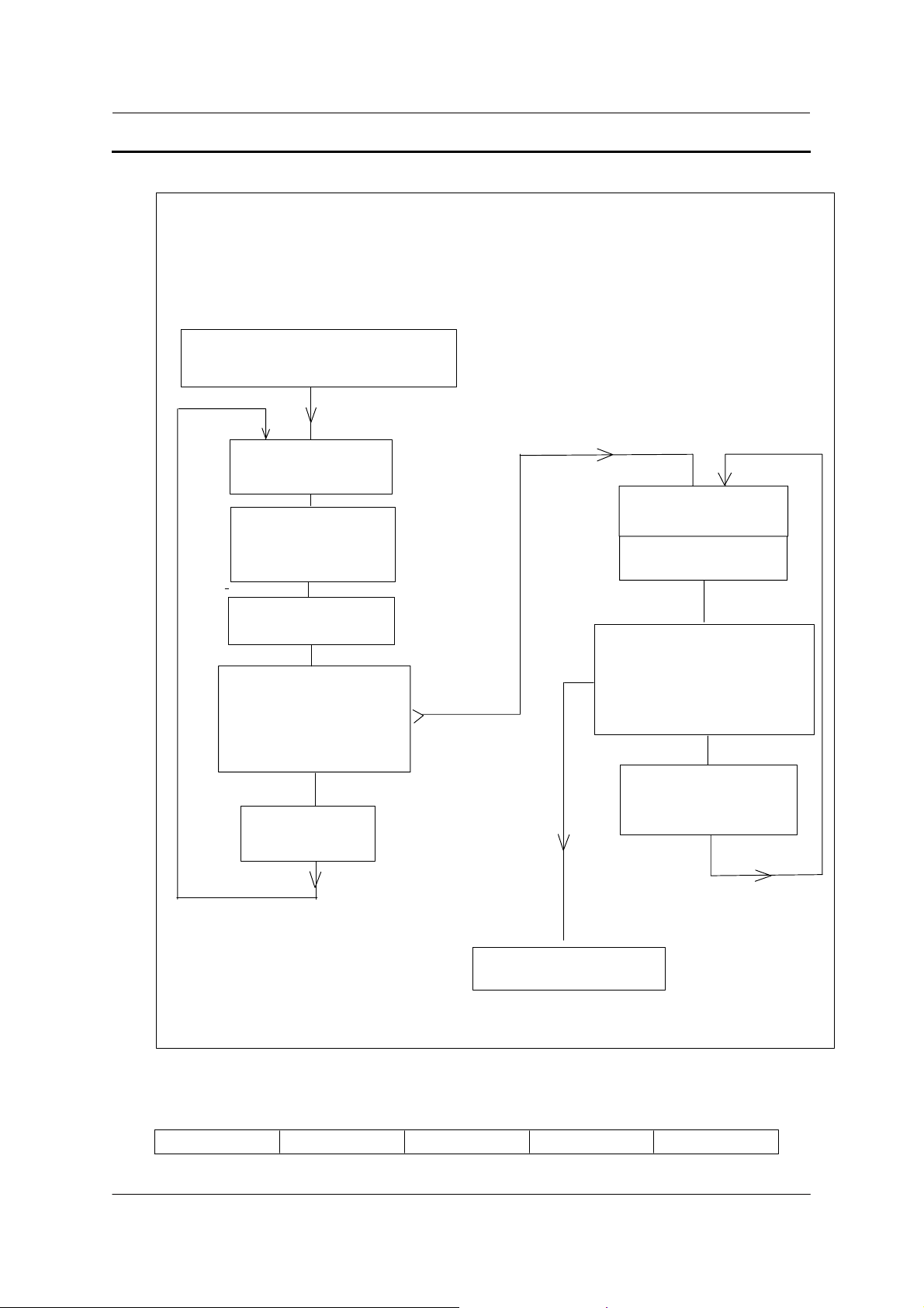
1 Upgrade synopsis
In-band code download on the A-CPSW
Save your configuration, to be able
to reload it in case of problems.
download A-CPSW
operational microcode
download A-CPSW
FPGA picocode
if necessary
(last level B52)
download A-CPSW
boot microcode
No
redundant CPSW, or
both CPSW
are downloaded
No
Make Redundant
A-CPSW active
step 2
step 3
step 4
step 5
Yes
step 1
Swap FPGA picocode
if necessary
Swap microcode
step 6
Noredundant CPSW, or
Yes
both A-CPSW microcode
are swapped ?
No
Make redundant
A-CPSW standby
step 8
Download completed
June 17 1998EC : F34705PN : 26L0227
Copyright IBM Corp. 1998
Page 3
Page 4

Installation Instructions
1.1 Prerequisites
The minimum FPGA level required for A-CPSW is B52.
1.2 Copying Operational/Boot and FPGA A-CPSW Codes
on your workstation
1.2 .1 Code from Distribution Diskettes
The present kit contains 2 diskettes :
1 The diskette, Part Number 26L0255, contains for A-CPSW 8260:
A notice file (READ8260.TXT)
A-CPSW FPGA picocde (SWPGAB52.ENC)
A-CPSW boot microcode (BOOTV319.BIN)
A soft copy of this installation instructions (II60V319.ps)
A soft copy of the release note (RN60V319.PS)
2 The diskette, Part Number 26L0256, contains:
A new MIB version 2.1 (8260V21.MIB)
A-CPSW operational microcode (8260V319.OPE)
1.2 .1.1 References
Release Note, Part number 26L0228, EC level F34705.
Installation Instructions for IBM Universal Code Download Kit, Part Number 80G3152
ATM Control Point and Switch Module, Installation and user's Guide (SA33-0326).
IBM 8285/8260 ATM Command Reference Guide (SA33-0385)
June 17 1998EC : F34705PN : 26L0227
Copyright IBM Corp. 1998
Page 4
Page 5

Installation Instructions
SA33-0452.
IBM 8260 Nways Multiprotocol Switching Hub
IBM 8285 Nways ATM Workgroup Switch
ATM Control Point Version 3
User's guide.
SA33-0453.
IBM 8260 Nways Multiprotocol Switching Hub
IBM 8285 Nways ATM Workgroup Switch
1.2 .1.2 Copying the Distribution Files on your workstation
1 Insert the distribution diskette part number 26L0255 in the workstation.
2 Copy from the diskette to the directory where you want the microcodes to reside, the following
files:
A-CPSW boot microcode, file name: BOOTV319.BIN.
A-CPSW FPGA picocode, file name: SWPGAB52.ENC.
3 Remove the distribution diskette part number 26L0255 from the workstation.
4 Insert the distribution diskette part number 26L0256 in the workstation.
5 Copy from the diskette to the directory where you want the microcodes to reside, the following
files:
A-CPSW operational microcode, file name: 8260V319.OPE.
6 Remove the distribution diskette part number 26L0256 from the workstation.
7 On an AIX Workstation make sure that the files can be read by all users :
Log in as "root"
Set the path to the microcode files directory
Enter: chmod a+r BOOTV319.BIN
Enter: chmod a+r 8260V319.OPE
Enter: chmod a+r SWPGAB52.ENC
1.2 .2 Code download from the Web
The code upgrade files posted on the Web are available to upgrade (or restore) a CPSW.
They consist of the boot and operational microcodes, the FPGA and MIB codes, so that text
files in plain text or PDF (Acrobat reader) format.
June 17 1998EC : F34705PN : 26L0227
Copyright IBM Corp. 1998
Page 5
Page 6

Installation Instructions
These files must be placed in a directory reachable through TFTP, like /tmp for a Unix/AIX
station, so that In-Band download toward the CPSW can be performed.
After package file has been downloaded and unzipped, on an AIX Workstation make sure
that the files can be read by all users :
Log in as "root" Set the
Enter: chmod a+r BOOTV319.BIN
Enter: chmod a+r 8260V319.OPE
Enter: chmod a+r SWPGAB52.ENC
path to the microcode files
directory
1.3 In-Band download method
You need to perform an inband download operation, using either:
ww
Classical IP mode. Make sure that your ATM network is configured for IP Over ATM
(RFC 1577). To configure your ATM network for IP over ATM:
1 Connect an ARP server to the ATM network. The ARP server will be used to map IP
addresses to ATM addresses.
2 For each A-CPSW module verify that the following parameters are configured:
Ø
ATM address of the ARP server
Ø
IP address and IP mask of the A-CPSW
Ø
IP address of the default gateway
3 Verify the IP connectivity to the ARP server by entering a PING command for each A-CPSW
module.
4 Verify the IP connectivity to the TFTP server by entering a PING command for each A-CPSW
module.
ww
Ethernet or Token Ring LAN-Emulation mode
Make sure your network is configured in Ethernet or Token Ring
LAN-Emulation.
To configure your network in Ethernet or Token Ring LAN-Emulation :
1. You must have an Ethernet or Token Ring LAN-Emulation Server configured and ready.
You can use the local LES of the 8260.
2. You must configure the Ethernet or Token Ring LAN-Emulation Client on your 8260.
3. You must have a TFTP Server somewhere in the IP network (either on the Emulated LAN,
either behind an IP Gateway), and the microcode files installed on that TFTP Server.
June 17 1998EC : F34705PN : 26L0227
Copyright IBM Corp. 1998
Page 6
Page 7

Installation Instructions
4. Check that you can PING the TFTP server from the 8260 LEC.
ww
Serial Line IP support (SLIP) mode.Make sure your workstation can act as a TFTP
server .
1. Set up a A-CPSW Configuration Console in SLIP Mode:
2. Then configuring the SLIP interface on the TFTP workstation will allow you to perform Inband
Download between your workstation and the A-CPSW.
3. The SLIP connection will be broken after a reset of the A-CPSW and connection will be
operational in normal mode.
1.4 Out of Band Download method
FPGA picocode cannot be downloaded using this method, only boot and operational.
Download can only be performed on active CPSW.
Once you have the code on your A-disk or hard disk, and you have connected your PC on the
RS232 port, using an RS232 emulated terminal, you have to type the following commands on
the command line:
MAINTAIN
DOWNLOAD OUT-OF-BAND BOOT (or OPERATIONAL)
You then have to choose the Xmodem protocol and select the path where your code is
located.
Note: This method is not recommended since it takes more time than the In-Band
method.
June 17 1998EC : F34705PN : 26L0227
Copyright IBM Corp. 1998
Page 7
Page 8

Installation Instructions
2 Upgrading the 8260
YOU SHOULD MIGRATE YOUR NETWORK CLUSTER BY CLUSTER AND YOU
SHOULD DOWNLOAD THE FPGA CODE AND MICROCODE ON ALL YOUR 8260
AND 8285 SWITCHES (in the cluster) BEFORE PERFORMING ANY SWAP
COMMAND.
Note that interoperability between v.2.x.x clusters and v.3.x.x peer groups is possible through
NNI/IISP respectively.
IMPORTANT
The following steps are showing an example of Inband Download.
You may log in to the A-CPSW console either locally using an ASCII terminal connected
to the A-CPSW console port, or remotely using a TELNET session. PLEASE, READ
WHAT FOLLOWS CAREFULLY :
1. If you have only one A-CPSW (no redundant) follow the steps 1 to 4 then the steps 6 to 8.
2. If you have two A-CPSWs modules (one redundant A-CPSW) follow the steps 1 to 5 for main
A-CPSW and the steps 2 to 4 then 6 for redundant A-CPSW .Then follow the steps 6, 7 and 8 on
main A-CPSW (see upgrade synopsis).
2.1 Step 1: Saving Configuration before the upgrade
It is recommended to perform the following steps with NO OPERATIONAL TRAFFIC
flowing in your ATM campus network. Typically, this would be scheduled as part of a
maintenance period. You should save all your configuration parameters before.
Before you begin the upgrade procedure we recommend to upload the configuration of each
8260 in your network :
1 Setup the TFTP parameters by entering the following commands:
SET TFTP SERVER_IP_ADDRESS <ip address of the TFTP server>
SET TFTP FILE_TYPE CONFIGURATION
SET TFTP FILE_NAME
Provide the full path of the file when prompted
2 Start the upload inband procedure by entering: UPLOAD
June 17 1998EC : F34705PN : 26L0227
Copyright IBM Corp. 1998
Page 8
Page 9

Installation Instructions
2.2 Step 2: Download Inband the 8260 A-CPSW
operational microcode
Upgrade the new active A-CPSW operational microcode as follows:
1 Configure the TFTP parameters by entering the following commands:
SET TFTP SERVER_IP_ADDRESS <ip address of the TFTP server>
SET TFTP FILE_TYPE OPERATIONAL
SET TFTP FILE_NAME
Type the full path name of the operational microcode file when prompted (its actual name is
indicated in the Readme file).
2 Make sure you can reach the TFTP server by entering:
PING <ip adress of the TFTP server>
(Stop PING by entering: Ctrl+C)
3 Start the download inband procedure by entering:
DOWNLOAD INBAND
When prompted, type "Y" to confirm.
4 Wait for successful termination of the download operation. The message
is displayed.
This may also be checked by displaying the TFTP last transfer result through the command:
"SHOW TFTP"
.
Download successful
The command "SHOW DEVICE" displays the downloaded operational code level as backup.
It should display : v. 3.1.9.
2.3 Step 3 : Download Inband the 8260 A-CPSW FPGA
picocode
This operation should be done only if your CPSW FPGA level is not uptodate, the latest
level is B52.
1 Configure the TFTP parameters by entering the following commands:
SET TFTP SERVER_IP_ADDRESS <ip address of the TFTP server>
SET TFTP FILE_TYPE FPGA
June 17 1998EC : F34705PN : 26L0227
Copyright IBM Corp. 1998
Page 9
Page 10
Installation Instructions
SET TFTP FILE_NAME
Type the full path name of the FPGA file when prompted
SET TFTP TARGET_MODULE <n>
SAVE TFTP
2 Make sure you can reach the TFTP server by entering:
PING <ip adress of the TFTP server>
(Stop PING by entering: Ctrl+C)
3 Start the download inband procedure by entering:
DOWNLOAD INBAND
When prompted, type "Y" to confirm.
4 Wait for successful termination of the download operation (it may take up to 10 minutes). The
message
This may also be checked by displaying the TFTP last transfer result with the command:
"SHOW TFTP".
Download successful
is displayed.
(n=9 or 11 depending of active A-CPSW position)
.
The command SHOW MODULE <n> VERBOSE (n=9 or 11 depending on A-CPSW active
position) displays the FPGA level in backup.
It should appear as B52.
2.4 Step 4: Download Inband the 8260 A-CPSW boot
microcode
Upgrade the new active A-CPSW boot microcode as follows:
1 Log in as the Administrator on the A-CPSW console
2 Perform the command:
SET DEVICE MIGRATION NOT_ALLOWED
3 Upgrade the A-CPSW boot microcode (Boot EEPROM) as follows:
Configure the TFTP parameters by entering the following commands:
SET TFTP SERVER_IP_ADDRESS <ip address of the TFTP server>
Ø
SET TFTP FILE_TYPE BOOT
Ø
SET TFTP FILE_NAME
Ø
Ø
Type the full path name of the boot microcode file when prompted (its actual name is
indicated in the Readme file).
June 17 1998EC : F34705PN : 26L0227
Copyright IBM Corp. 1998
Page 10
Page 11

Installation Instructions
Make sure you can reach the TFTP server by entering:
PING <ip address of the TFTP server>
(Stop PING by entering: Ctrl+C)
Start the download inband procedure by entering:
DOWNLOAD INBAND
Wait for successful termination of the download operation. The message Download
successful is displayed.
This may also be checked by displaying the TFTP last transfer result with the command:
"SHOW TFTP".
When prompted, type
"Y"
to confirm.
The command "SHOW DEVICE" displays the new BOOT code version which will become
active after an A-CPSW reset.
It should display: v.3.1.9.
If you have only one A-CPSW module go to step 6.
If you were upgrading your backup A-CPSW module go to step
6.
2.5 Step 5: Make the backup A-CPSW active
If you have a redundant A-CPSW make the backup one active by entering on the active
A-CPSW:
SET DEVICE ROLE SECONDARY
SAVE ALL
RESET ATM_SUBSYSTEM
Log in as the Administrator on the A-CPSW console
The hub will reset and the backup A-CPSW will become active. GO TO STEP 2.
2.6 Step 6: Activate the new A-CPSW microcodes and the
new FPGA picocode
DO NOT PERFORM ANY SWAP BEFORE HAVING DOWNLOADED :
1 OPERATIONAL CODE
June 17 1998EC : F34705PN : 26L0227
Copyright IBM Corp. 1998
Page 11
Page 12
Installation Instructions
2 FPGA CODE (If necessary)
3 BOOT CODE
4 Activate the new version of A-CPSW FPGA. picocode by entering the command:
SAVE ALL
SWAP FPGA_PICOCODE 9 (or 11).The telnet session, if any, is broken.
Login as Administrator on the A-CPSW console.
5 Activate the new version of A-CPSW microcode by entering the command:
SWAP MICROCODE
have to connect locally an ASCII terminal to the A-CPSW console port to get the connectivity
again.
Login as Administrator on the A-CPSW ASCII console.
6 If you do not have redundant A-CPSW, go to step 7.
If you had already swapped new FPGA picocode and microcode on both A-CPSW
modules go to step 7. Check the new levels of codes .
The following table lists the microcode and FPGA versions that
must be displayed at completion of the upgrade. Use the following commands
SHOW DEVICE
SHOW MODULE <n> VERBOSE
and confirm with
FPGA versionComponent
Y. Your remote TELNET session is broken and you
Flash EEPROM
version
Boot EEPROM
Version
v.3.1.9 v.3.1.9 B52A-CPSW
Now make this A-CPSW be secondary again as it was before the beginning of the
migration :
SET DEVICE ROLE SECONDARY
SAVE ALL
RESET ATM_SUBSYSTEM
The hub will reset and the backup A-CPSW will become active.
Perform the step 6 again on the other A-CPSW.
June 17 1998EC : F34705PN : 26L0227
Copyright IBM Corp. 1998
Page 12
Page 13

Installation Instructions
2.7 Step 7: Check the new levels of codes :
1 Login as ADMINISTRATOR on the active A-CPSW console
2 The following table lists the microcode and FPGA versions that must be displayed at
completion of the upgrade. Use the following commands
SHOW DEVICE
SHOW MODULE n VERBOSE
FPGA versionComponent
Flash EEPROM
version
Boot EEPROM
Version
v.3.1.9 v.3.1.9 B52A-CPSW
WARNING
Because of the major differences of operations between PNNI-1 and SSI, all your PVC
are cleared, all logical links and static routes will be deleted.
Before performing any swap, record your network parameters for LOGICAL LINK,
STATIC ROUTE, ATM ADDRESS and VPC (record those information on a sheet of
paper):
Example for CLUSTER 1:
1. HUBb>SHOW LOGICAL_LINK ALL will display
PORT VPI ACN SIDE MODE SIG TRAF BWITH STATUS INDEX
3.1 3 02 USER ENABLE 3.1 ANY 85000 UP 1
2. HUBb>SHOW STATIC ROUTE will display :
INDEX ACN STATIC ROUTE
1 02 39.99.99.99.99.99.99.00.00.88.88.03
3. HUBb>SHOW DEVICE will display :
ATM ADDRESS: 39.99.99.99.99.99.99.00.00.77.77.01.02.00.00.82.60.01.02.00
4. HUBb>SHOW PVC ALL will display :
port id type Vpi/Vci Port Vpi/Vci Hnb Party Role QOS Status
1.01 4 PTM-PVC 1/50 4.01 2/40 3 0 Primary BE
Active
June 17 1998EC : F34705PN : 26L0227
Copyright IBM Corp. 1998
Page 13
Page 14

Installation Instructions
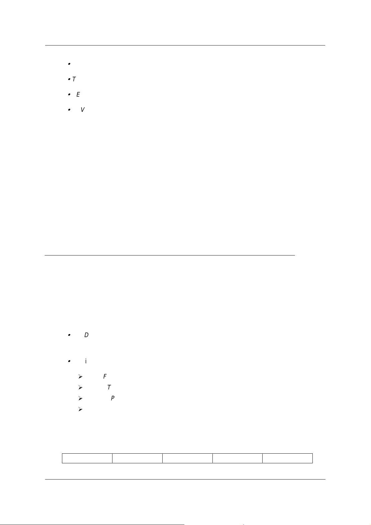
2.8 SET MINIMUM PNNI PHASE-1 PARAMETERS.
NOTE THAT INTEROPERABILITY BETWEEN V.2.X.X CLUSTERS AND
V.3.X.X PEER-GROUPS IS POSSIBLE THROUGH NNI AND IISP LINK
RESPECTIVELY.
Figure 2, represents a network configured with 8260/8285 at the ATM firmware
kit level MES5099. In this example there are two subnetworks (X and Y), three
clusters and four hubs, using UNI/SSI/NNI links. You should recognize in this
drawing the different components of your current network.
June 17 1998EC : F34705PN : 26L0227
Copyright IBM Corp. 1998
Page 14
Page 15

Installation Instructions
Subnetwork X (ATM address 39.99.99.99.99.99.0.9.77.77)
Cluster 1 (ACN=1)
WS 1
UNI
4.3
3.2 2.1
SSI
HUB a (HN=1)
Subnetwork Y (ATM address 39.99.99.99.99.99.99.0.0.88.88)
HUB b (HN=2)
3.1
vpi3
Cluster 2 (ACN=2)
4.1 5.1
vpi3
NNI
HUB c (HN=1)
Cluster 3 (ACN=3)
WS 2
NNI vpi0
WS 3
4.3
HUB d (HN=1)
6.1
Figure 2. Example of a network at the ATM firware kit level(MES 5099).
June 17 1998EC : F34705PN : 26L0227
Copyright IBM Corp. 1998
Page 15
Page 16

Installation Instructions
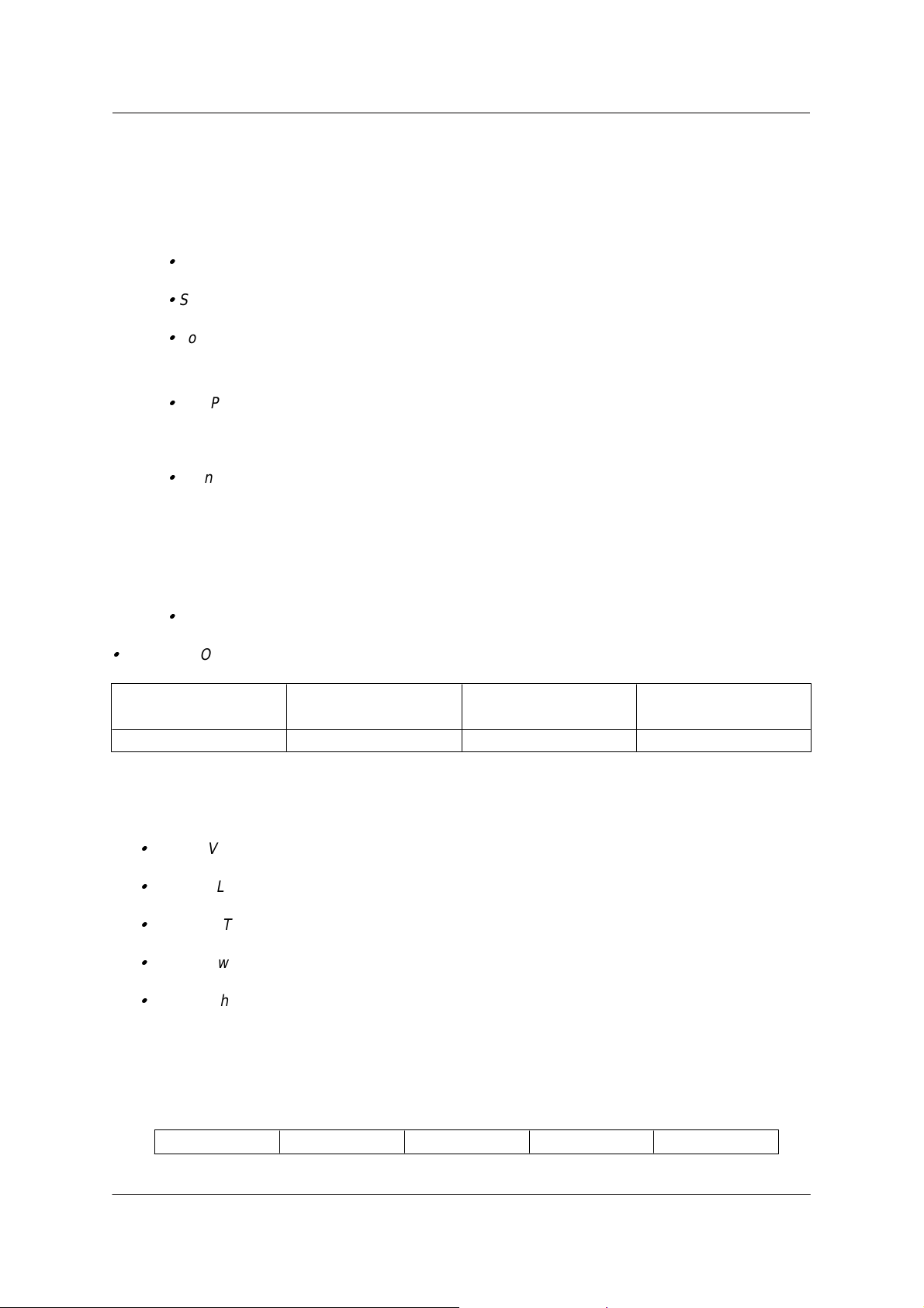
2.8 .1 Example of a migration to PNNI phase 1 (SEE FIGURE 3)
Figure 3 represents your network after migration to PNNI phase-1 (v.3.1.0).
You can note that
CLUSTER changes to PEER GROUP
SSI changes to PNNI
NNI changes to IISP.
June 17 1998EC : F34705PN : 26L0227
Copyright IBM Corp. 1998
Page 16
Page 17

Installation Instructions
Subnetwork X (ATM address 39.99.99.99.99.99.0.9.77.77)
Peer Group 1
WS 1
UNI
4.3
3.2 2.1
PNNI
HUB a (HN=1)
Subnetwork Y (ATM address 39.99.99.99.99.99.99.0.0.88.88)
HUB b (HN=2)
3.1
vpc3
IISP
void
Peer Group 2
4.1 5.1
vpc3
HUB c (HN=1)
Peer Group 3
WS 2
IISP vpc0
WS 3
4.3
HUB d (HN=1)
Figure 3. Example of a network in level PNNI phase 1 (v.3.1.0)
Copyright IBM Corp. 1998
June 17 1998EC : F34705PN : 26L0227
6.1
Page 17
Page 18

Installation Instructions
2.8 .1.1 Migration of PEER GROUP 1 - HUB a
---ATM ADDRESS SETTING ---------------------------------------------------
After having completed the swap, the ATM address has been migrated to the Node-0
ATM address, but the PNNI Summary Address was set to a default value. So you need
to enter the old ATM address again, with a new selector, by issuing the following
command :
o HUBa>set pnni node_0 atm_address:
39.99.99.99.99.99.99.00.00.77.77.01.01.00.00.82.60.01.01.01
o HUBa>SHOW FUTURE_PNNI NODE_0
Check your new ATM address.
o HUBa>COMMIT PNNI , the 8260 will be reset
The telnet session if any is broken.
Login as ADMINISTRATOR on the 8260 console.
o HUBa>SHOW PNNI NODE_0
Check your ATM address. It will display information about : LEVEL
ID, PEERGROUP ID, NODE ID.
--- PORT SETTING ---------------------------------------------------------------AUTOMATICALLY MIGRATED.
--- VIRTUAL PATH CHANNELS SETTING (VPCS) : --------------------------------
No VPC links need to be defined
--- REACHABLE ADDRESS SETTING : ------------------------------------------No REACHABLE ADDRESS need to be defined
2.8 .1.2 Migration of PEER GROUP 1 - HUB b
June 17 1998EC : F34705PN : 26L0227
Copyright IBM Corp. 1998
Page 18
Page 19

Installation Instructions
--- ATM ADDRESS SETTING ---------------------------------------------------
After having completed the swap, the ATM address has been migrated to the
Node-0 ATM address, but the PNNI Summary Address was set to a default value.
So you need to enter the old ATM address again, with a new selector, by issuing the
following command :
o HUBb>set pnni node_0 atm_address:
39.99.99.99.99.99.99.00.00.77.77.01.02.00.00.82.60.01.02.01
o HUBb>SHOW FUTURE_PNNI NODE_0
Check your new ATM address.
o HUBb>COMMIT PNNI, the 8260 will be reset
The telnet session if any is broken.
Login as ADMINISTRATOR on the 8260 console.
o HUBb>SHOW PNNI NODE_0
Check your ATM address. It will display information about : LEVEL
ID, PEERGROUP ID, NODE ID.
---- PORT SETTING -----------------------------------------------------------------
After having completed the swap, the SSI port automatically became an enabled PNNI
port and the NNI port became a disabled IISP port, so you need to re-enable the IISP
port only:
1. Enable all your old NNI port (now IISP) as VOID port.
HUBb>SET PORT 3.1 ENABLE VOID
2. SETTING FOR UNI PORT. No change is needed for the port set as UNI
before the migration, the port 4.3 of HUBb has been left after migration as UNI
enabled.
--- VIRTUAL PATH CHANNELS SETTING (VPCS) : --------------------------------
June 17 1998EC : F34705PN : 26L0227
Copyright IBM Corp. 1998
Page 19
Page 20

Installation Instructions
For each LOGICAL LINK in v2.x.x (if VPI was not equal to 0) you must define a VPC
link in v3.1.0 :
1. To set your new VPC_LINKS, YOU NEED THE V2.X.X PARAMETERS YOU
HAVE WRITTEN DOWN IN STEP 6.
example for old CLUSTER 1 HUB b (figure2), now PEER GROUP 1,HUB b (fig 3):
The VPI on the LOGICAL LINK 3.1 was 3.
Use VPI 3 to set up the new VPC_LINK.
HUBb>SET VPC_LINK 3.1 3 ENABLE IISP USER BANDWIDTH:85000
--- REACHABLE ADDRESS SETTING : -------------------------------------------
After having completed the swap, you lose your STATIC ROUTES and LOGICAL
LINKS
o Define the reachable address over the IISP link with your old static route and your
old VPI.
example for PEER GROUP 1 HUBb (figure3):
HUBb>SET REACHABLE_ADDRESS
3.1 96 39.99.99.99.99.99.99.00.00.77.77.02 VPI:3
3.1 96 39.99.99.99.99.99.99.00.00.88.88.03 VPI:3
o Check that your reachable address is active (Y) with the command:
example for PEER GROUP 1 HUBb (figure3):
HUBb>SHOW REACHABLE_ADDRESS 3.1
June 17 1998EC : F34705PN : 26L0227
Copyright IBM Corp. 1998
Page 20
Page 21

Installation Instructions
2.8 .1.3 Migration of PEER GROUP 2 - HUB c
--- ATM ADDRESS SETTING ---------------------------------------------------
After having completed the swap, the ATM address has been migrated to the Node-0
ATM address, but the PNNI Summary Address was set to a default value. So you need
to enter the old ATM address again, with a new selector, by issuing the following
command :
o HUBc>set pnni node_0 atm_address:
39.99.99.99.99.99.99.00.00.77.77.02.01.00.00.82.60.02.01.01
o HUBc>SHOW FUTURE_PNNI NODE_0
Check your new ATM address.
o HUBc>COMMIT PNNI, the 8260 will be reset
The telnet session if any is broken.
Login as ADMINISTRATOR on the 8260 console.
o HUBc>SHOW PNNI NODE_0
Check your ATM address. It will display information about : LEVEL
ID, PEERGROUP ID, NODE ID.
--- PORT SETTING ----------------------------------------------------------
After having completed the swap, all the NNI ports will become disa bled IISP ports, so you need to re-enable them : enable all your old
NNI ports (now IISP) as VOID ports.
1. HUBc>SET PORT 4.1 ENABLE VOID
2. Because in the example the vpc between hubc and hubd is ZERO, you can
define the port 5.1 as IISP:
HUBc>SET PORT 5.1 ENABLE IISP
3. SETTING FOR UNI PORT. No change is needed for the port set as UNI
before the migration.
June 17 1998EC : F34705PN : 26L0227
Copyright IBM Corp. 1998
Page 21
Page 22

Installation Instructions
--- VIRTUAL PATH CHANNELS SETTING (VPCS) : --------------------------------
For each LOGICAL LINK in v2.x.x (if VPI was not equal to 0) you must
define a VPC link in v3.1.0 :
1. To set your new VPC_LINKS, YOU NEED THE V2.X.X PARAMETERS YOU
HAVE WRITTEN DOWN IN STEP 6.
example for old CLUSTER 2 HUBc (figure2), now PEER GROUP 2,HUB c:
The VPI on the LOGICAL LINK 4.1 was 3.
Use VPI 3 to set up the new VPC_LINK on PORT 4.1.
HUBc>SET VPC_LINK 4.1 3 ENABLE IISP NETWORK
BANDWIDTH:85000
---REACHABLE ADDRESS SETTING : -------------------------------------------
After having completed the swap, you lose your STATIC ROUTES and LOGICAL LINKS
o Define the reachable address over the IISP link with your old static
route and your old VPI.
example to set up reachability to PEER GROUP 1 HUBb (figure3):
HUBc>SET REACHABLE_ADDRESS
4.1 96 39.99.99.99.99.99.99.00.00.77.77.01 VPI:3
example to set up reachability to PEER GROUP 3 HUBd (figure3):
HUBc>SET REACHABLE_ADDRESS
5.1 96 39.99.99.99.99.99.99.00.00.88.88.03
o Check that your reachable address is active (Y) with the command:
HUBc>SHOW REACHABLE_ADDRESS 5.1
HUBc>SHOW REACHABLE_ADDRESS 4.1
June 17 1998EC : F34705PN : 26L0227
Copyright IBM Corp. 1998
Page 22
Page 23

Installation Instructions
2.8 .1.4 Migration of PEER GROUP 3 - HUB d
--- ATM ADDRESS SETTING ---------------------------------------------------
After having completed the swap, the ATM address has been migrated to the Node-0
ATM address, but the PNNI Summary Address was set to a default value. So you need
to enter the old ATM address again, with a new selector, by issuing the following
command :
o HUBd>set pnni node_0 atm_address:
39.99.99.99.99.99.99.00.00.88.88.03.01.D0.E0.20.15.16.17.19
o HUBd>SHOW FUTURE_PNNI NODE_0
Check your new ATM address.
o HUBd>COMMIT PNNI, the 8260 will be reset
The telnet session if any is broken.
Login as ADMINISTRATOR on the 8260 console.
o HUBd>SHOW PNNI NODE_0
Check your ATM address. It will display information about : LEVEL
ID, PEERGROUP ID, NODE ID.
--- PORT SETTING ----------------------------------------------------------
After having completed the swap, your NNI port will become a disabled IISP port, so
you need to re-enable it :
Enable your old NNI port (now IISP) as IISP
Because in the example, the VPC between hubd and hubc is ZERO, you can define the
port 6.1 as IISP:
HUBd> SET PORT 6.1 ENABLE IISP
--- VIRTUAL PATH CHANNELS SETTING (VPCS) : --------------------------------
No VPCs links need to be defined
June 17 1998EC : F34705PN : 26L0227
Copyright IBM Corp. 1998
Page 23
Page 24

Installation Instructions
--- REACHABLE ADDRESS SETTING : -------------------------------------------
After having completed the swap, you lose your STATIC ROUTES and LOGICAL
LINKS
o Define the reachable address over the IISP link with your old static
route and your old VPI.
example to set up reachability to PEER GROUP 1 HUBa and b (figure3):
HUBd>SET REACHABLE_ADDRESS
6.1 96 39.99.99.99.99.99.99.00.00.77.77.01
example to set up reachability to PEER GROUP 2 HUBc (figure3):
HUBd>SET REACHABLE_ADDRESS
6.1 96 39.99.99.99.99.99.99.00.00.77.77.02
o Check that your reachable address is active (Y) with the command:
HUBd>SHOW REACHABLE_ADDRESS 6.1
--- NOW TRY TO PING.. ----------------------------------------------------
To be sure you have successfuly completed PNNI installation, in the case
you have set TCP/IP parameters in a classical IP or LAN Emulation
network, enter from HUB b, PING x.y.z.w where x.y.z.w is the HUB c ip
address then enter from HUB b, PING a.b.c.d where a.b.c.d is the HUB d ip
address
--- MIGRATION COMPLETE ----------------------------------------------------
You have successfully completed the MES 5511 upgrade.
June 17 1998EC : F34705PN : 26L0227
Copyright IBM Corp. 1998
Page 24
Page 25

Installation Instructions
2.9 PUBLICATION UPDATE
Insert the companion Release Note, Part number 26L0228, EC level F34705 in your
publications binder.
END OF DOCUMENT
June 17 1998EC : F34705PN : 26L0227
Copyright IBM Corp. 1998
Page 25
 Loading...