

Page 1

RS/6000
7012 Models 300 Series
Installation and Service Guide
SA38–0545–00
Page 2

First Edition (October 1997)
This edition notice applies to the
edition obsoletes all previous editions.
The following paragraph does not apply to the United Kingdom or any country where such
provisions are inconsistent with local law: THIS PUBLICATION IS PRINTED “AS IS” WITHOUT
WARRANTY OF ANY KIND, EITHER EXPRESS OR IMPLIED, INCLUDING, BUT NOT LIMITED TO, THE
IMPLIED WARRANTIES OF MERCHANTABILITY OR FITNESS FOR A PARTICULAR PURPOSE. Some
states do not allow disclaimer of express or implied warranties in certain transactions; therefore, this
statement may not apply to you.
This publication could include technical inaccuracies or typographical errors. Changes are periodically made
to the information herein; these changes will be incorporated in new editions of the publication.
It is possible that this publication may contain reference to, or information about, products (machines and
programs), programming, or services that are not announced in your country. Such references or
information must not be construed to mean that such products, programming, or services will be offered in
your country. Any reference to a licensed program in this publication is not intended to state or imply that
you can use only the licensed program indicated. You can use any functionally equivalent program instead.
AIX is a registered trademark of International Business Machines Corporation.
Copyright International Business Machines Corporation, 1991, 1997. All rights reserved.
Note to US Government Users – Documentation and programs related to restricted rights – Use,
duplication, or disclosure is subject to the restrictions set forth in the GSA ADP Schedule Contract.
R/S6000 7012 Models 300 Series Installation and Service Guide.
This
Page 3

Table of Contents
Communications Statements vii. . . . . . . . . . . . . . . . . . . . . . . . . . . . . . . . . . . . . . . . . . . .
Safety Notices xi. . . . . . . . . . . . . . . . . . . . . . . . . . . . . . . . . . . . . . . . . . . . . . . . . . . . . . . . . .
About This Book xiii. . . . . . . . . . . . . . . . . . . . . . . . . . . . . . . . . . . . . . . . . . . . . . . . . . . . . . . .
Chapter 1. Reference Information 1-1. . . . . . . . . . . . . . . . . . . . . . . . . . . . . . . . . . . . . . . .
System Unit Locations 1-1. . . . . . . . . . . . . . . . . . . . . . . . . . . . . . . . . . . . . . . . . . . . . . . . . . . .
Front View with Covers, Early Models 1-1. . . . . . . . . . . . . . . . . . . . . . . . . . . . . . . . . . . .
Front View with Covers, Later Models 1-2. . . . . . . . . . . . . . . . . . . . . . . . . . . . . . . . . . . .
Rear View without Covers, Models 320, 32E, 32H 1-2. . . . . . . . . . . . . . . . . . . . . . . . .
Rear View without Covers, Models 340, 34H, 350, 355, 360/36T, 365,
370/37T, 375 1-3. . . . . .
Rear View Models 380, 390, 39H, and 397 1-3. . . . . . . . . . . . . . . . . . . . . . . . . . . . . . . .
Front View without Covers, Early Models 1-4. . . . . . . . . . . . . . . . . . . . . . . . . . . . . . . . .
Front View without Covers – Later Models 1-4. . . . . . . . . . . . . . . . . . . . . . . . . . . . . . . .
Front View without Covers – Model 397 1-5. . . . . . . . . . . . . . . . . . . . . . . . . . . . . . . . . .
System Planar Connector Locations, Models 320, 32E, 32H 1-5. . . . . . . . . . . . . . . .
System Planar Connector Locations, Models 355, 365, 375 1-6. . . . . . . . . . . . . . . .
System Planar Connector Locations, Models 340, 34H, 350, 360/36T, 370/37T 1-6
System Planar Connector Locations Models 380 and 390 1-7. . . . . . . . . . . . . . . . . . .
System Planar Connector Locations Model 39H 1-7. . . . . . . . . . . . . . . . . . . . . . . . . . .
System Planar Connector Locations Model 397 1-8. . . . . . . . . . . . . . . . . . . . . . . . . . .
CPU Card Locations 1-8. . . . . . . . . . . . . . . . . . . . . . . . . . . . . . . . . . . . . . . . . . . . . . . . . . .
Memory 1-9. . . . . . . . . . . . . . . . . . . . . . . . . . . . . . . . . . . . . . . . . . . . . . . . . . . . . . . . . . . . . . . .
Model 39H 1-9. . . . . . . . . . . . . . . . . . . . . . . . . . . . . . . . . . . . . . . . . . . . . . . . . . . . . . . . . . . .
Model 397 1-9. . . . . . . . . . . . . . . . . . . . . . . . . . . . . . . . . . . . . . . . . . . . . . . . . . . . . . . . . . . .
Data and Power Flow 1-10. . . . . . . . . . . . . . . . . . . . . . . . . . . . . . . . . . . . . . . . . . . . . . . . . . . .
Bus-Attached Disk Drives, Models 320, 32E, and 32H 1-10. . . . . . . . . . . . . . . . . . . . . .
SCSI-Attached Disk Drives, Models 340, 34H, 350, 360/36T, 370/37T 1-11. . . . . . . .
SCSI-Attached Disk Drives, Models 355, 365, 375 1-11. . . . . . . . . . . . . . . . . . . . . . . . .
Data and Power Flow: SCSI Attached Disk Drives – Models 380, 390, 39H 1-12. . .
Data and Power Flow: SCSI Attached Disk Drives – Model 397 1-13. . . . . . . . . . . . . .
Specifications (all models except 380, 390, 39H, and 397) 1-14. . . . . . . . . . . . . . . . . . . .
Specifications Models 380, 390, 39H, and 397 1-15. . . . . . . . . . . . . . . . . . . . . . . . . . . . . . .
Power Cables 1-16. . . . . . . . . . . . . . . . . . . . . . . . . . . . . . . . . . . . . . . . . . . . . . . . . . . . . . . . . . .
Service Inspection Guide 1-17. . . . . . . . . . . . . . . . . . . . . . . . . . . . . . . . . . . . . . . . . . . . . . . . .
Chapter 2. Maintenance Analysis Procedures (MAPS) 2-1520-1. . . . . . . . . . . . . . . . . . . . .
MAP 1520: 7012 Power MAP 2-1520-1. . . . . . . . . . . . . . . . . . . . . . . . . . . . . . . . . . . . . . . . . . . . . .
MAP 1540: 7012 Minimum Machine Configuration 2-1540-1. . . . . . . . . . . . . . . . . . . . . . . . . . .
Chapter 3. Removal and Replacement Procedures 3-1. . . . . . . . . . . . . . . . . . . . . . . .
Preface iii
Page 4

Handling Static-Sensitive Devices 3-2. . . . . . . . . . . . . . . . . . . . . . . . . . . . . . . . . . . . . . . . . .
Rear Cover 3-3. . . . . . . . . . . . . . . . . . . . . . . . . . . . . . . . . . . . . . . . . . . . . . . . . . . . . . . . . . . . .
Top Cover 3-4. . . . . . . . . . . . . . . . . . . . . . . . . . . . . . . . . . . . . . . . . . . . . . . . . . . . . . . . . . . . . .
Front Cover 3-6. . . . . . . . . . . . . . . . . . . . . . . . . . . . . . . . . . . . . . . . . . . . . . . . . . . . . . . . . . . . .
Disk Drive (Bus-Attached): Models 320, 32E, 32H 3-8. . . . . . . . . . . . . . . . . . . . . . . . . . . .
Disk Drive (SCSI-Attached): Models 320, 32E, 32H 3-10. . . . . . . . . . . . . . . . . . . . . . . . . .
Disk Drive (SCSI-Attached): Models 340, 34H, 350, 355, 360/36T, 365,
370/37T, 375 3-12. . . . . .
Disk Drive: Models 380, 390, 39H, and 397 3-14. . . . . . . . . . . . . . . . . . . . . . . . . . . . . . . . .
Power Supply 3-16. . . . . . . . . . . . . . . . . . . . . . . . . . . . . . . . . . . . . . . . . . . . . . . . . . . . . . . . . . .
Power Supply (Models 380, 390, 39H, and 397) 3-18. . . . . . . . . . . . . . . . . . . . . . . . . . . . .
Diskette Drive 3-20. . . . . . . . . . . . . . . . . . . . . . . . . . . . . . . . . . . . . . . . . . . . . . . . . . . . . . . . . . .
Media Drive Removal for Models 380, 390, 39H, and 397 3-22. . . . . . . . . . . . . . . . . . . . .
Adapter Cards, Ethernet Riser Card, and External Diskette Riser Card 3-24. . . . . . . . . .
Setting the Ethernet Riser Card Jumpers 3-26. . . . . . . . . . . . . . . . . . . . . . . . . . . . . . . . . . . .
Attached Devices 3-28. . . . . . . . . . . . . . . . . . . . . . . . . . . . . . . . . . . . . . . . . . . . . . . . . . . . . . . .
CPU Card 3-30. . . . . . . . . . . . . . . . . . . . . . . . . . . . . . . . . . . . . . . . . . . . . . . . . . . . . . . . . . . . . .
CPU Card (Model 39H) 3-31. . . . . . . . . . . . . . . . . . . . . . . . . . . . . . . . . . . . . . . . . . . . . . . . . . .
Voltage Regulator Card (Model 39H) 3-33. . . . . . . . . . . . . . . . . . . . . . . . . . . . . . . . . . . . . . .
L2 Cache 3-34. . . . . . . . . . . . . . . . . . . . . . . . . . . . . . . . . . . . . . . . . . . . . . . . . . . . . . . . . . . . . . .
Fan and Air Duct (Model 39H Only) 3-35. . . . . . . . . . . . . . . . . . . . . . . . . . . . . . . . . . . . . . . .
Memory Card 3-37. . . . . . . . . . . . . . . . . . . . . . . . . . . . . . . . . . . . . . . . . . . . . . . . . . . . . . . . . . .
Memory SIMMs 3-39. . . . . . . . . . . . . . . . . . . . . . . . . . . . . . . . . . . . . . . . . . . . . . . . . . . . . . . . . .
System Planar 3-40. . . . . . . . . . . . . . . . . . . . . . . . . . . . . . . . . . . . . . . . . . . . . . . . . . . . . . . . . . .
Card Guide Frame 3-43. . . . . . . . . . . . . . . . . . . . . . . . . . . . . . . . . . . . . . . . . . . . . . . . . . . . . . .
Rear Fan 3-45. . . . . . . . . . . . . . . . . . . . . . . . . . . . . . . . . . . . . . . . . . . . . . . . . . . . . . . . . . . . . . .
Front Fan 3-46. . . . . . . . . . . . . . . . . . . . . . . . . . . . . . . . . . . . . . . . . . . . . . . . . . . . . . . . . . . . . . .
Key Lock 3-48. . . . . . . . . . . . . . . . . . . . . . . . . . . . . . . . . . . . . . . . . . . . . . . . . . . . . . . . . . . . . . .
Reset Switch 3-50. . . . . . . . . . . . . . . . . . . . . . . . . . . . . . . . . . . . . . . . . . . . . . . . . . . . . . . . . . . .
Serial Ports Flex Circuit (Models 340, 34H, 350, 355, 360/36T, 365,
370/37T, 375) 3-52. . . . . .
Serial Port (Models 380, 390, 39H, and 397) 3-53. . . . . . . . . . . . . . . . . . . . . . . . . . . . . . . .
Three-Digit Display: Models 320, 32E, 32H 3-54. . . . . . . . . . . . . . . . . . . . . . . . . . . . . . . . . .
Three-Digit Display Models 340, 34H, 350, 355, 360/36T, 365,
370/37T, and 375, 380, 390, 39H 3-55. . . . . .
Three-Digit Display, Model 397 3-56. . . . . . . . . . . . . . . . . . . . . . . . . . . . . . . . . . . . . . . . . . . .
T oroids 3-57. . . . . . . . . . . . . . . . . . . . . . . . . . . . . . . . . . . . . . . . . . . . . . . . . . . . . . . . . . . . . . . . .
Battery 3-58. . . . . . . . . . . . . . . . . . . . . . . . . . . . . . . . . . . . . . . . . . . . . . . . . . . . . . . . . . . . . . . . .
Contact Strips (Models 340, 34H, 350, 355, 360/36T, 365, 370/37T, 375) 3-59. . . . . . . .
Chapter 4. System Installation 4-1. . . . . . . . . . . . . . . . . . . . . . . . . . . . . . . . . . . . . . . . . . .
Chapter 5. Parts Information 5-1. . . . . . . . . . . . . . . . . . . . . . . . . . . . . . . . . . . . . . . . . . . . .
Appendix A. SCSI Device Address Record A-1. . . . . . . . . . . . . . . . . . . . . . . . . . . . . . . .
Index X-1. . . . . . . . . . . . . . . . . . . . . . . . . . . . . . . . . . . . . . . . . . . . . . . . . . . . . . . . . . . . . . . . . .
iv Installation and Service Guide
Page 5

Communications Statements
The following statement applies to this product. The statement for other products intended
for use with this product will appear in their accompanying manuals.
Federal Communications Commission (FCC) Statement
Note: This equipment has been tested and found to comply with the limits for a Class A
digital device, pursuant to Part 15 of the FCC Rules. These limits are designed to
provide reasonable protection against harmful interference when the equipment is
operated in a commercial environment. This equipment generates, uses, and can
radiate radio frequency energy and, if not installed and used in accordance with the
instruction manual, may cause harmful interference to radio communications.
Operation of this equipment in a residential area is likely to cause harmful
interference in which case the user will be required to correct the interference at his
own expense.
Properly shielded and grounded cables and connectors must be used in order to meet FCC
emission limits. Neither the provider or the manufacturer are responsible for any radio or
television interference caused by using other than recommended cables and connectors or
by unauthorized changes or modifications to this equipment. Unauthorized changes or
modifications could void the user’s authority to operate the equipment.
This device complies with Part 15 of the FCC Rules. Operation is subject to the following
two conditions: (1) this device may not cause harmful interference, and (2) this device must
accept any interference received, including interference that may cause undesired
operation.
European Union (EU) Statement
This product is in conformity with the protection requirements of EU Council Directive
89/336/EEC on the approximation of the laws of the Member States relating to
electromagnetic compatibility. The manufacturer cannot accept responsibility for any failure
to satisfy the protection requirements resulting from a non–recommended modification of
the product, including the fitting of option cards supplied by third parties. Consult with your
dealer or sales representative for details on your specific hardware.
This product has been tested and found to comply with the limits for Class A Information
Technology Equipment according to CISPR 22 / European Standard EN 55022. The limits
for Class A equipment were derived for commercial and industrial environments to provide
reasonable protection against interference with licensed communication equipment.
This is a Class A product. In a domestic environment this product may cause radio
interference in which case the user may be required to take adequate measures.
International Electrotechnical Commission (IEC) Statement
This product has been designed and built to comply with IEC Standard 950.
Preface v
Page 6
United Kingdom Telecommunications Safety Requirements
This equipment is manufactured to the International Safety Standard EN60950 and as such
is approved in the UK under the General Approval Number NS/G/1234/J/100003 for indirect
connection to the public telecommunication network.
The network adapter interfaces housed within this equipment are approved separately, each
one having its own independent approval number. These interface adapters, supplied by the
manufacturer, do not use or contain excessive voltages. An excessive voltage is one which
exceeds 70.7 V peak ac or 120 V dc. They interface with this equipment using Safe Extra
Low Voltages only. In order to maintain the separate (independent) approval of the
manufacturer’s adapters, it is essential that other optional cards, not supplied by the
manufacturer, do not use main voltages or any other excessive voltages. Seek advice from
a competent engineer before installing other adapters not supplied by the manufacturer.
Avis de conformité aux normes du ministère des Communications du
Canada
Cet appareil numérique de la classe A respecte toutes les exigences du Réglement sur le
matériel brouilleur du Canada.
Canadian Department of Communications Compliance Statement
This Class A digital apparatus meets the requirements of the Canadian
Interference-Causing Equipment Regulations.
VCCI Statement
The following is a summary of the VCCI Japanese statement in the box above.
This equipment is in the Class 1 category (information equipment to be used in
commercial and/or industrial areas) and conforms to the standards set by the Voluntary Control Council For Interference by Data Processing Equipment and Electronic Office Machines aimed at preventing radio interference in commercial and/
or industrial areas.
Consequently , when used in a residential area or in an adjacent area thereto, radio
interference may be caused to radios and TV receivers, etc.
Read the instructions for correct handling. VCCI–1.
vi Installation and Service Guide
Page 7

Electromagnetic Interference (EMI) Statement – Taiwan
The following is a summary of the EMI Taiwan statement above.
Warning: This is a Class A product. In a domestic environment this product may cause
radio interference in which case the user will be required to take adequate measures.
Radio Protection for Germany
Dieses Gerät ist berechtigt in Übereinstimmung mit dem deutschen EMVG vom 9.Nov.92
das EG-Konformitätszeichen zu führen.
Der Aussteller der Konformitätserklärung ist die IBM Germany.
Dieses Gerät erfüllt die Bedingungen der EN 55022 Klasse A. Für diese Klasse von
Geräten gilt folgende Bestimmung nach dem EMVG:
Geräte dürfen an Orten, für die sie nicht ausreichend entstört sind, nur mit besonderer
Genehmigung des Bundesministers für Post und Telekommunikation oder des
Bundesamtes für Post und Telekommunikation betrieben werden. Die Genehmigung wird
erteilt, wenn keine elektromagnetischen Störungen zu erwarten sind.
(Auszug aus dem EMVG vom 9.Nov.92, Para.3, Abs.4)
Hinweis:
Dieses Genehmigungsverfahren ist von der Deutschen Bundespost noch nicht veröffentlicht
worden.
Preface vii
Page 8

viii Installation and Service Guide
Page 9

Safety Notices
Note: For a translation of these notices, see
Number SA23-2652.
Definitions of Safety Notices
A
danger
or serious personal injury.
Danger
2-1520-1
3-18
3-28
4-2
A
caution
moderate or minor personal injury.
Caution
2-1520-1
3-28
3-58
4-2
4-3
notice indicates the presence of a hazard that has the potential of causing death
notices appear on the following pages:
notice indicates the presence of a hazard that has the potential of causing
notices appear on the following pages:
System Unit Safety Information
, Order
Preface ix
Page 10
Laser Safety Information
Note: The Optical Link Card (OLC) referred to in this information is part of the Serial Optic
Channel Converter assembly.
This system contains a laser product called the Optical Link Card (OLC). In the U.S., the
OLC is certified as a Class 1 laser product that conforms to the requirements contained in
the Department of Health and Human Services (DHHS) regulation 21 CFR Subchapter J.
Internationally, the OLC is certified as a Class 1 laser product that conforms to the
requirements contained in the International Electrotechnical Commission (IEC) standard 825
(1984), the Verband Deutscher Elektrotechniker (VDE) standard 0837 (1986), and the
CENELEC (European Committee for Electrotechnical Standardization) Harmonization
Document HD 482 S1 (1988). The German testing institute VDE assigned a certificate of
conformity to DIN IEC 825/VDE 0837/02.86 and CENELEC HD 482 S1/03.88; the certificate
registration number is 3642.
In addition, Statens Provningsanstalt (Swedish National Testing Institute) tested and
approved the OLC for use in Sweden as a Class 1 laser product and assigned the approval
number SP LA 89:184. The CDRH certification label and the VDE certificate of conformity
mark are located on the plastic retainer of the OLC product. Figure 1 shows the system
Class 1 information label required by IEC 825.
Class 1 laser products are not considered to be hazardous. The OLC internally contains a
gallium aluminum arsenide (GaAlAs) semiconductor laser diode emitting in the wavelength
range of 770 to 800 nanometers. This laser diode is a Class 3B laser that is rated at 5.0
milliwatts. The design of the OLC is such that access to laser radiation above a Class 1
level during operation, user maintenance, or service conditions is prevented.
CLASS 1 LASER PRODUCT
LASER KLASSE 1
LUOKAN 1 LASERLAITE
APPAREIL A LASER DE CLASSE 1
TO IEC 825:1984/CENELEC HD 482 S1
Figure 1. Class 1 System Information Label Required by the IEC 825 Standard
The Optical Link Card (OLC) must only be connected to another OLC or a compatible laser
product. Any compatible laser product must contain the open fiber link detection and laser
control safety system used in OLC. This is a requirement for correct operation of the optical
link. In addition, the OLC product is designed and certified for use in applications with
point-to-point optical links only. Using this product in any other type of optical link
configuration (for example, links containing optical splitters or star couplers) is considered
as not using the product correctly and may require that the user certify the laser product
again for conformance to the laser safety regulations.
x Installation and Service Guide
Page 11

About This Book
This book uses three-digit model numbers. You may have other documentation that uses
four-digit model numbers. For example, the model 32H in this book may be referred to as a
model 320H in other documentation. They are the same system units.
This book provides maintenance information that is specific to the 7012 system unit,
adapters, and attached devices that do not have their own service information. It also
contains Maintenance Analysis Procedures (MAPs) that are not common to other systems.
MAPs that are common to all systems are contained in
Channel Bus Systems
This book is used by the service technician for initial installation and to repair system
failures. This book assumes that the service technician has had training on the 7012
unit.
All information in this book pertaining to 7012 Model 397 also applies to 7030 Model 397.
Related Information
The
Diagnostic Information For Micro Channel Bus Systems
Section I, contains the maintenance information and procedures that are common to all
systems. The information and procedures in this book apply to any system unit that uses
the Diagnostic Programs. Section II contains reference information about adapters, devices,
and cabling for the system units. This manual also contains the removal and replacement
procedures for the logic boards on the disk drives. This manual provides the service
representative pin-out lists and cabling information to use in isolating problems with
customer cabling.
System Unit Safety Information
the danger and caution notices.
The
7012 300 Series Operator Guide
about the controls and features of the system unit.
Diagnostic Information For Micro
.
system
, Order Number SA23-2765,
, Order Number SA23-2652, contains translated versions of
, Order Number SA23-2623, provides information
The
Diskless Workstation Management Guide,
information about diskless workstations.
Each attached device has a
the information needed for that device.
Setup and Operator Guide
Order Number SC23–2433, contains
and
a Service Guide
that provides
Preface xi
Page 12
Chapter 1. Reference Information
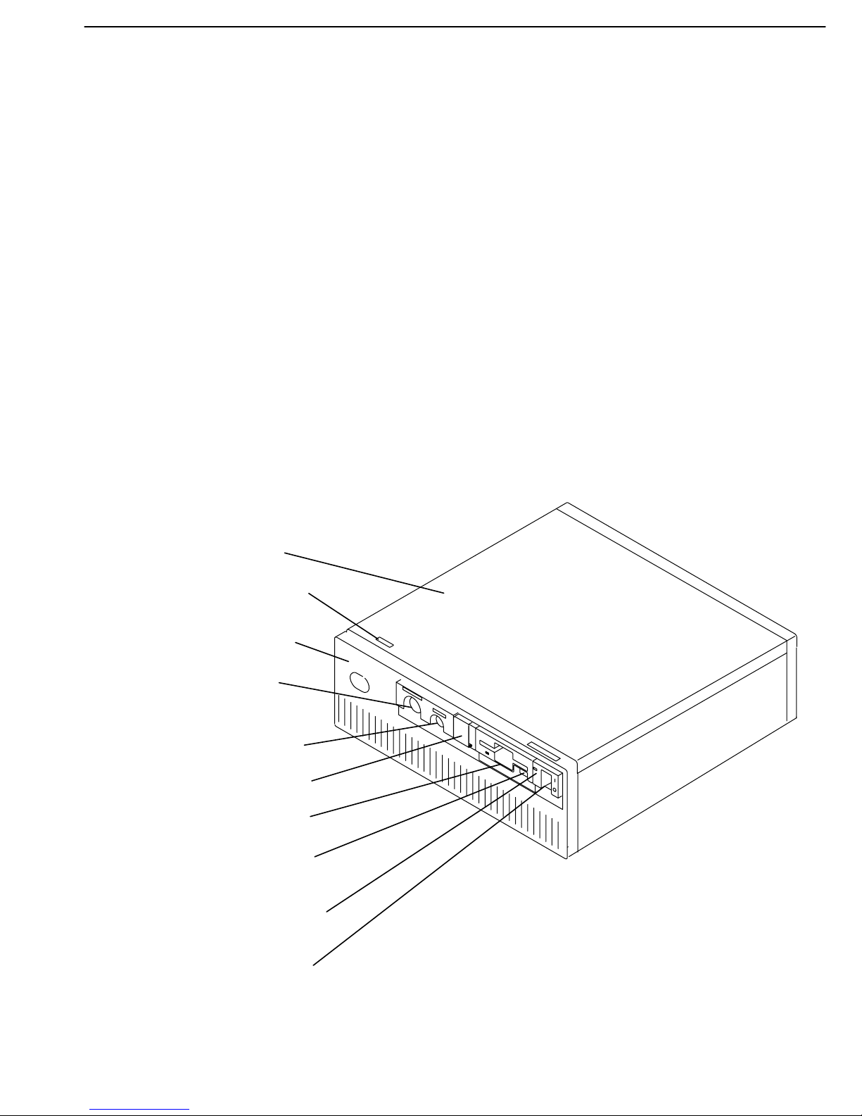
System Unit Locations
Use the following views of the system unit to locate the disk drive positions, connectors, and
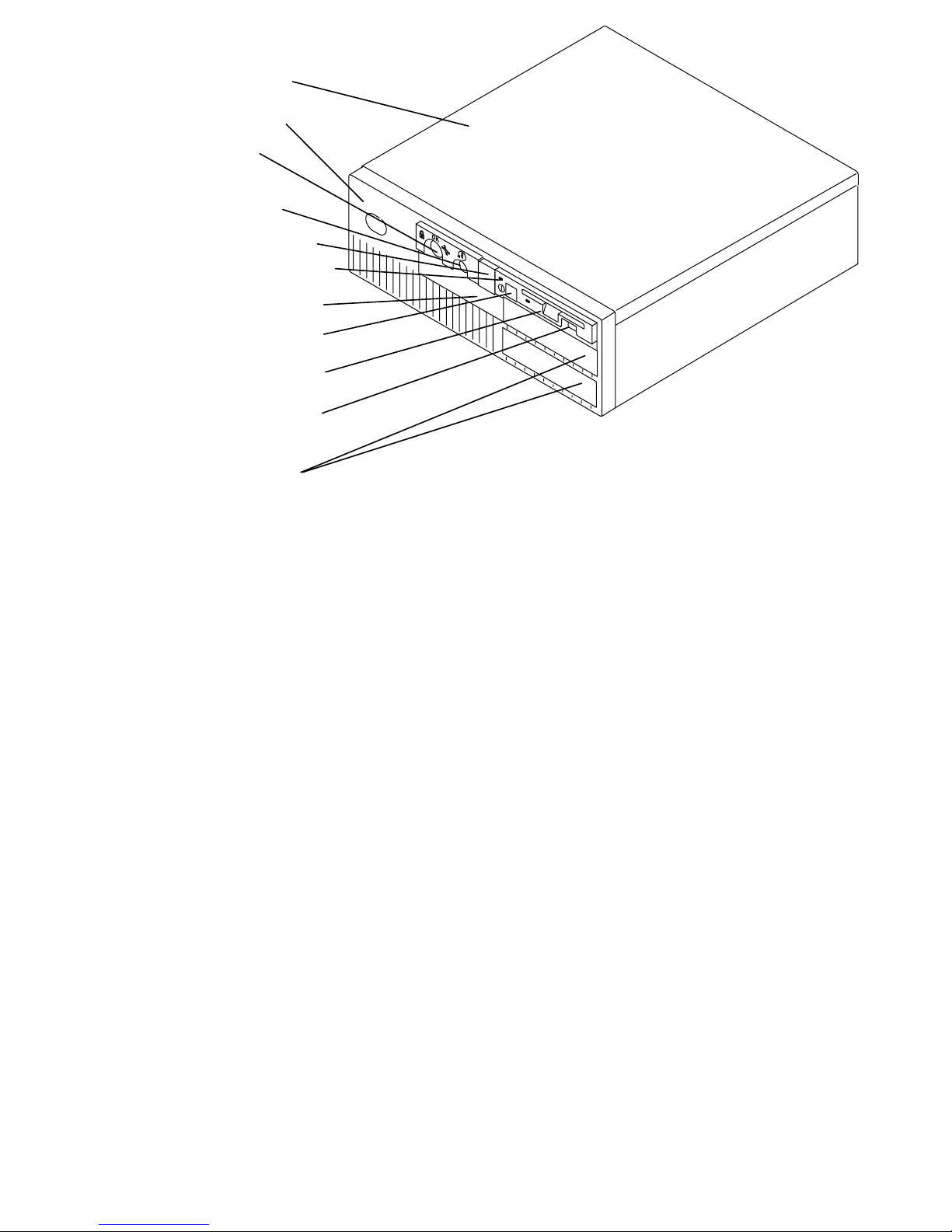
system board slot positions. The front of your system unit will resemble one of the following
two illustrations.
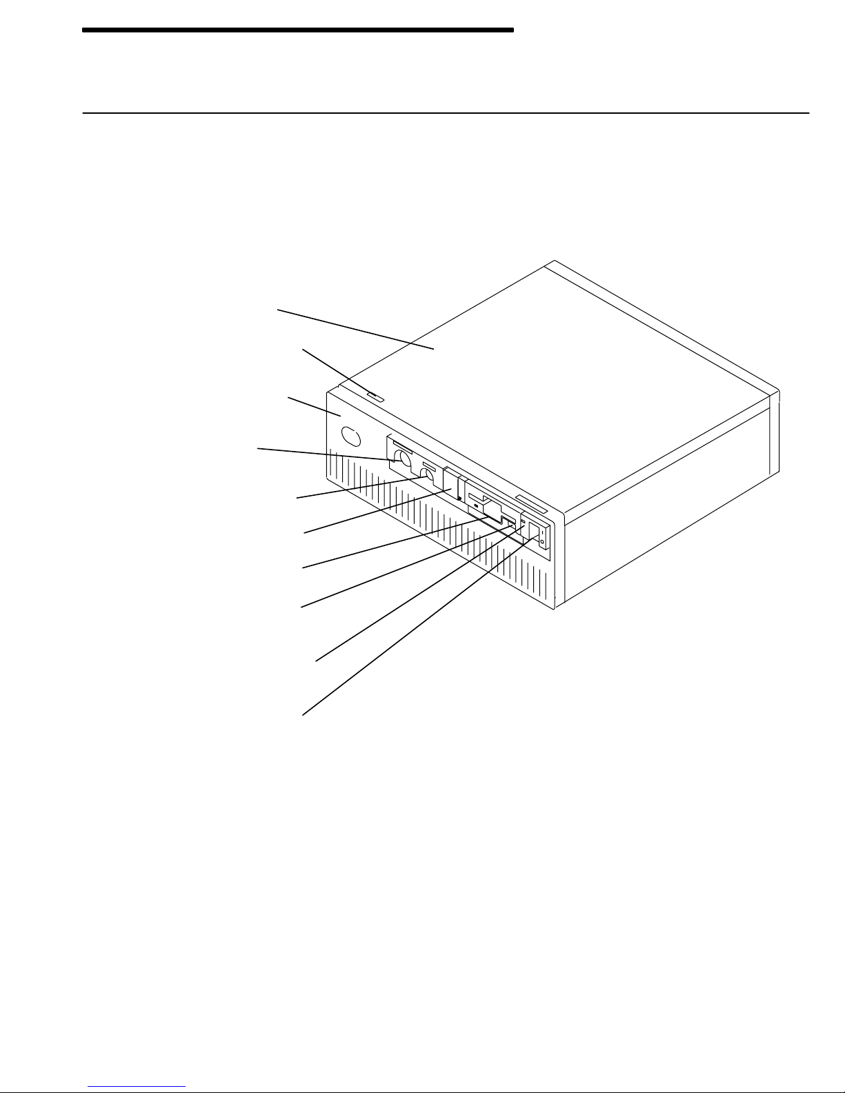
Front View with Covers, Early Models
Top Cover
Serial Number
Front Cover
Key Mode
Switch
Reset Button
3-Digit Display
Diskette Drive
Diskette-Eject
Button
Power-On Light
Power Switch
Reference Information 1-1
Page 13
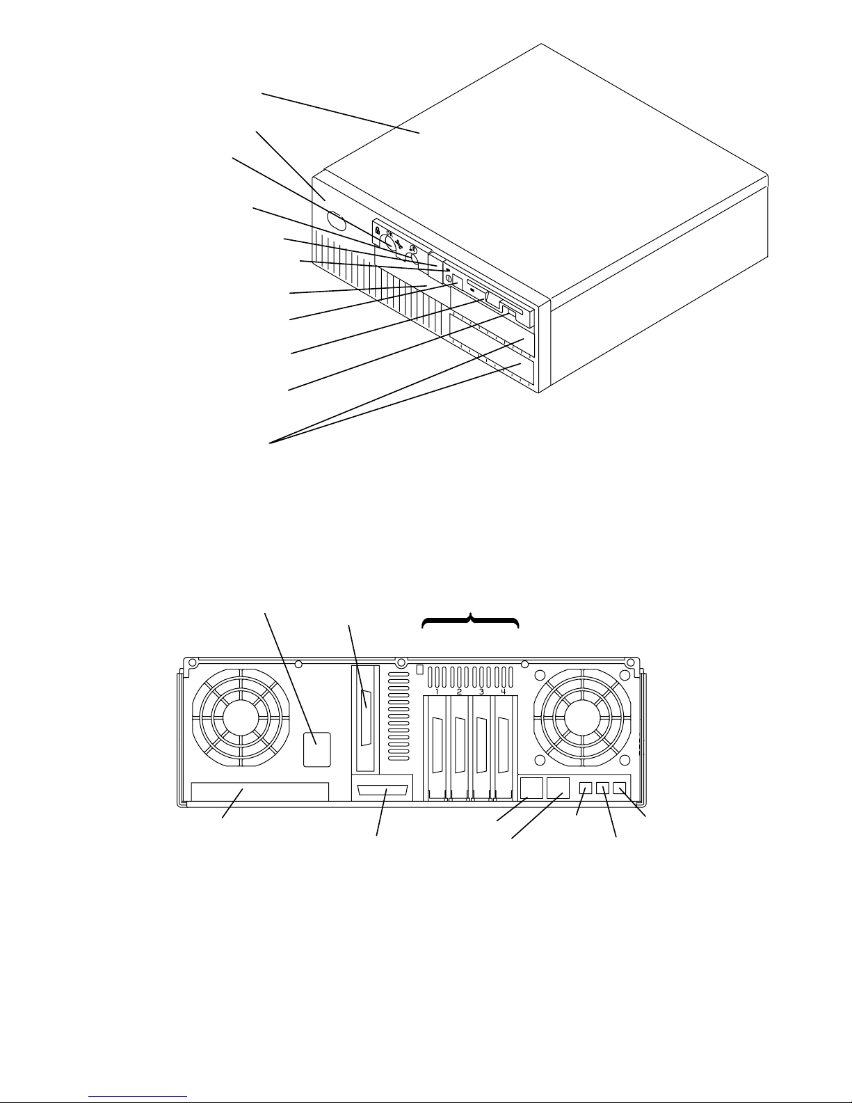
Front View with Covers, Later Models
Top Cover
Front Cover
Key Lock
Reset Button
3-Digit Display
Power-On Light
Serial Number
Power Button
Diskette Drive
Diskette-Eject
Button
Optional
Media Bays
Rear View without Covers, Models 320, 32E, 32H
Power
Plate
(Not on
all models)
Ethernet
Connector
Parallel Port
Adapter Positions
1234
Serial 1
Serial 2
Tablet
Mouse
Keyboard
1-2 Installation and Service Guide
Page 14
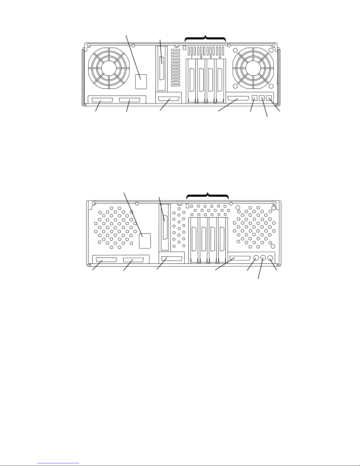
Rear View without Covers, Models 340, 34H, 350, 355, 360/36T, 365,
370/37T, 375
Power
Ethernet
SCSI PortSerial 1 Serial 2
Adapter Positions
Parallel Port
Rear View Models 380, 390, 39H, and 397
Power
Ethernet
Adapter Positions
Tablet
Mouse
Keyboard
S 1 S2
P
SCSI-2 PortSerial 1 Serial 2
Parallel Port
Tablet
Keyboard
Mouse
Reference Information 1-3
Page 15
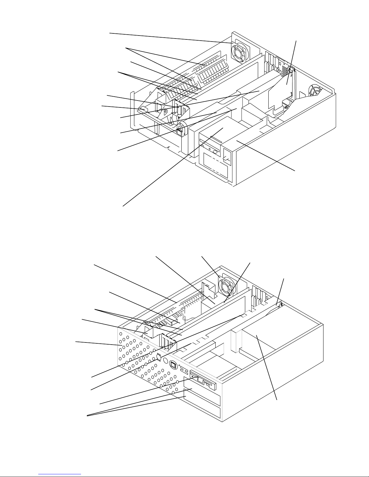
Front View without Covers, Early Models
The front of your system unit will resemble one of the following two illustrations.
Rear Fan
Memory Cards
CPU Card
Adapter and
Graphics Cards
Front Fan
Battery
Disk Drive C
Disk Drive D
Direct Bus
Attach Riser
Card
or
SCSI Bus
Extender Card
Ethernet Riser Card
Power Supply
Diskette Drive A
Front View without Covers – Later Models
Heat Sink
Memory Card
Memory Card or
Voltage Regulator
Card (Model 39H)
Adapter Cards
Front Fan
Multichip Cool-
ing Fan
(attached inside
the chassis)
Disk Drive C
Rear Fan
CPU Card or
CPU/Memory (Model 39H)
Ethernet Riser Card
Disk Drive D
Diskette Drive
Media Bays
1-4 Installation and Service Guide
Power Supply
Page 16
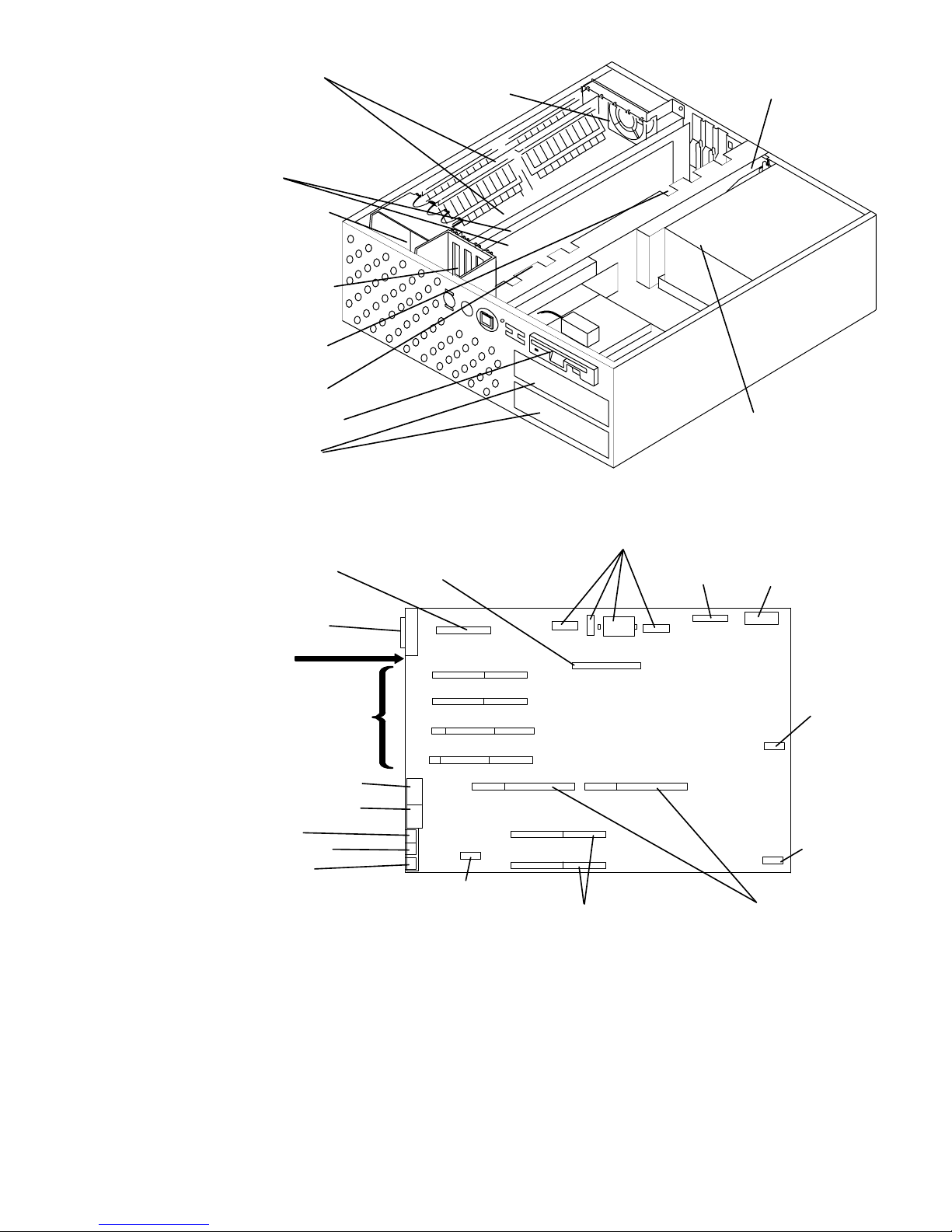
Front View without Covers – Model 397
Memory Card
(up to four)
Rear Fan
Adapter Cards
(up to four)
CPU Cooling
Fan and Heat
Sink
Adapter Card
Cooling Fan
Disk Drive C
Disk Drive D
Ethernet Riser Card
Diskette Drive
Media Bays
Power Supply
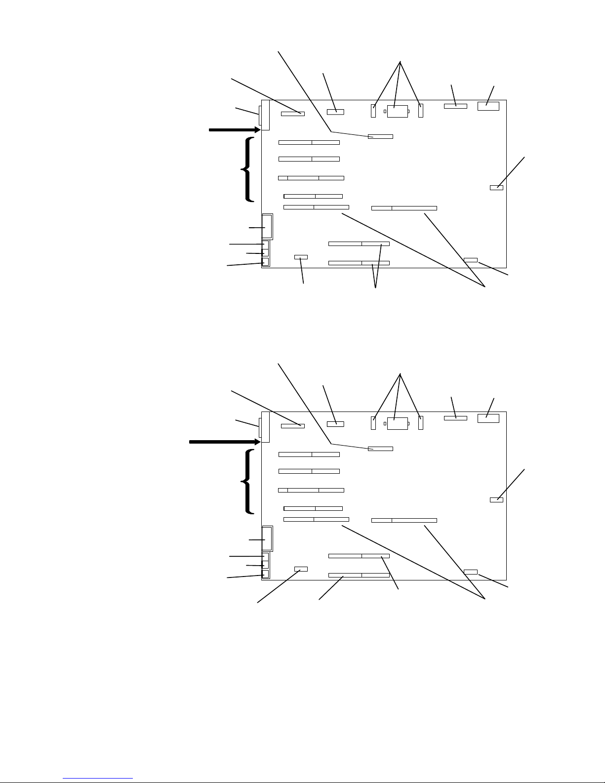
System Planar Connector Locations, Models 320, 32E, 32H
External Diskette
Adapter Card
Parallel Port
Rear of
System Unit
I/O Slots
Serial Port 1 (S1)
Serial Port 2 (S2)
Tablet (T)
Keyboard (K)
Mouse (M)
Disk Drive
Riser Card
J6
1
2
3
4
J5
J19
J18
J17
J1
J24
J14 J15
J7
Power Supply
J3
J25
J11
J10
J9
J8
J13
J12
B
C
J2
J4
J16
Diskette
J20
J22
A
J23
3-Digit
Display
J21
Key Mode
Switch
and Reset
Button
Battery
Rear Fan (Use
Optional cable,
(if provided)
Memory Cards CPU Card
Reference Information 1-5
Page 17
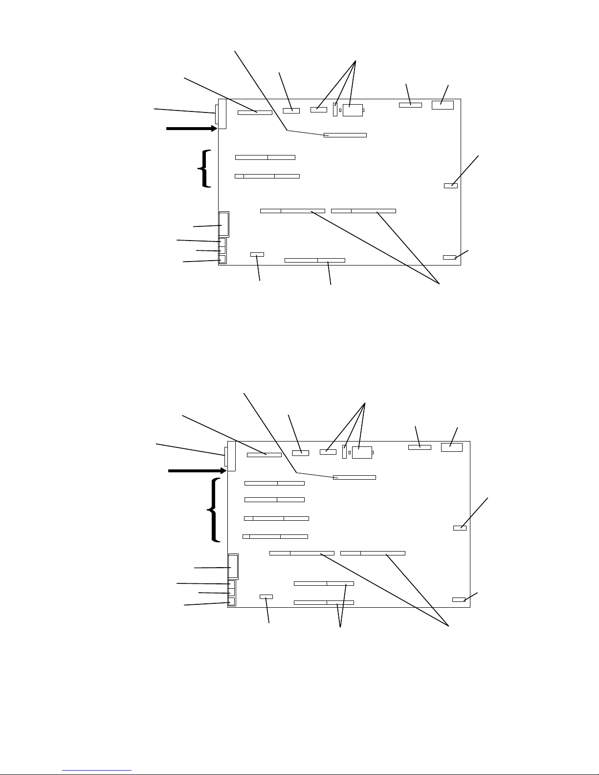
System Planar Connector Locations, Models 355, 365, 375
SCSI Bus
Extender Card
Ethernet
Riser Card
Serial Port
Extender
Cable
Power Supply
Diskette
3-Digit
Display
SCSI
Rear of
System Unit
I/O Slots
Parallel Port
Tablet (T)
Keyboard (K)
Mouse (M)
J16
J14
2
3
J8
J6
J7
J5
J1
Rear Fan Memory Card CPU Card
J27J15
J12
J11
J9 J19
J17
J25
J2
C
J24
J20
A
J22
J23
J21
Key Mode
Switch
and Reset
Button
Battery
System Planar Connector Locations, Models 340, 34H, 350, 360/36T,
370/37T
SCSI Bus
Extender Card
Ethernet
Riser Card
Serial Port
Extender
Cable
Power Supply
Diskette
3-Digit
Display
SCSI
Rear of
System Unit
I/O Slots
Parallel Port
Tablet (T)
Keyboard (K)
Mouse (M)
J16
J14
1
2
3
4
J8
J6
J7
J5
J1
Rear Fan Memory Cards CPU Card
J27J15
J13
J12
J11
J10
J9 J19
J18
J17
J25
J2
B
C
J20
J24
A
J23
J22
J21
Key Mode
Switch
and Reset
Button
Battery
1-6 Installation and Service Guide
Page 18
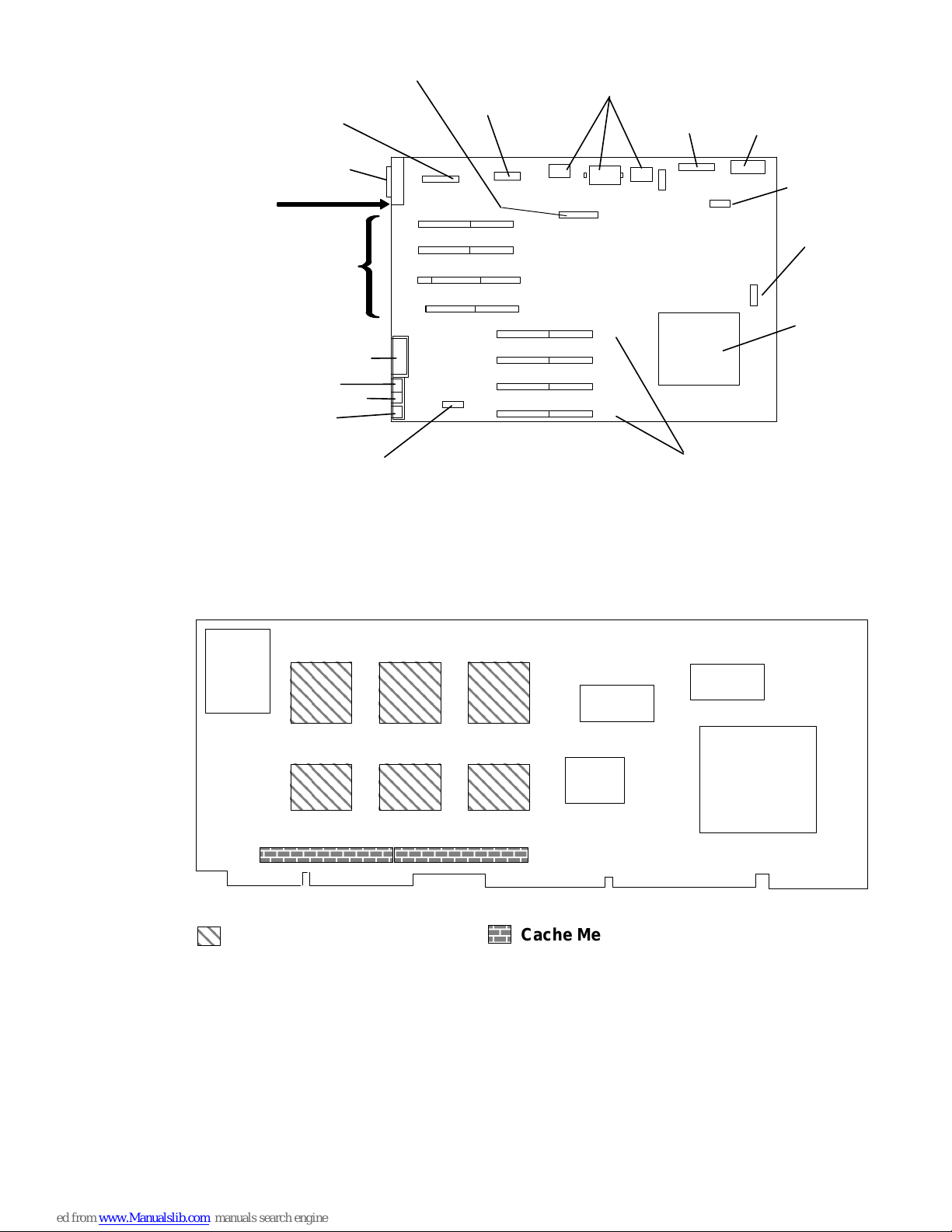
System Planar Connector Locations Models 380 and 390
SCSI Internal
Serial Port
Extender
Cable
J15
J8
J6
J7
J5
J1
Rear Fan Memory Cards CPU Card
J16
J9
Power Supply
J13
J12
J11
J10
J18
J17
J2J27
J19
B
C
Diskette
J20
J25
J24
A
Ethernet
Riser Card
SCSI-2
External
Rear of
System Unit
I/O Slots
Parallel Port
Tablet (T)
Keyboard (K)
Mouse (M)
Connector
J14
1
2
3
4
J22
3-Digit
Display
J23
J21
Key Mode
Switch
Reset
Button
Battery
System Planar Connector Locations Model 39H
SCSI Internal
Serial Port
Extender
Cable
J15
J8
J6
J5
J1
J9
J7
Memory Card
J16
Power Supply
J13
J12
J11
J10
J18
J17
H
Voltage Regulator
Card
Ethernet
Riser Card
SCSI-2
External
Rear of
System Unit
I/O Slots
Parallel Port
Tablet (T)
Keyboard (K)
Mouse (M)
Connector
J14
1
2
3
4
Rear Fan
J2J27
J24
J19
J25
Diskette
J20
J22
D (Memory)
A (CPU)
Memory and CPU
Card
Three-Digit
Display
J23
J21
Battery
Key Mode
Switch
Reset
Button
Reference Information 1-7
Page 19
System Planar Connector Locations Model 397
ББББББ
SCSI Internal
J8
J6
J5
J1
Serial Port
Extender
Cable
J15
J16
J7
Power Supply
J2J3
J13
J12
J11
J10
J28
J19
J18
J17
Ethernet
Riser Card
SCSI-2
External
Rear of
System Unit
I/O Slots
Parallel Port
Tablet (T)
Keyboard (K)
Mouse (M)
Connector
J14
1
2
3
4
Rear Fan Memory Cards
J24
F
B
D
H
J27
Diskette
J20
J25
J21
Three-Digit
Display
J23
J22
Battery
Key Mode
Switch
Reset
Button
CPU
CPU Card Locations
CPU Card, Models 380 and 390
Heat Sinks
Cache Memory
1-8 Installation and Service Guide
Page 20
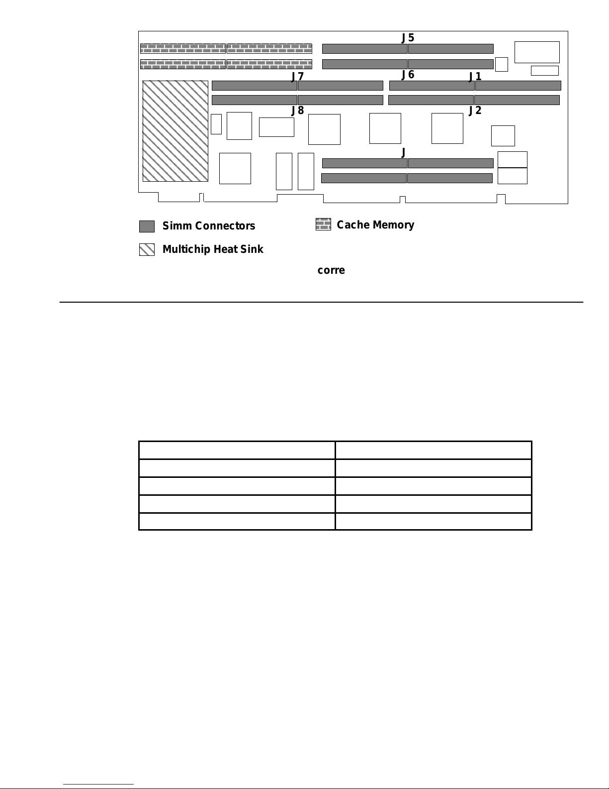
CPU Card, Model 39H
Memory
1
2
Simm Connectors
Multichip Heat Sink
Note: The numbers shown above correspond to actual SIMM locations.
J7
J8
Cache Memory
J5
J6
J3
J4
J1
J2
Model 39H
Model 397
The CPU card for the Model 39H has a different module arrangement than previous CPU
cards. Half of the memory is located on the CPU card, the other half is located on the
memory card.
The memory must be installed in pairs. Both memory pairs must have the same amount of
memory (MB). The following table pertains only to the Model 39H.
Memory on CPU Card
32MB CPU Memory SIMM (Base) 32MB Memory Card (Base)
64MB CPU Memory SIMM 64MB Memory Card
128MB CPU Memory SIMM 128MB Memory Card
256MB CPU Memory SIMM 256MB Memory Card
The memory modules for Model 397 must be installed either in pairs (2 cards) or quads (4
cards). Each card in a pair or quad must be of equal capacity.
If only a pair of memory modules is installed, use slots D and H. If a quad is installed, use
slots B and F, in addition to slots D and H.
Memory in Slot H
Reference Information 1-9
Page 21
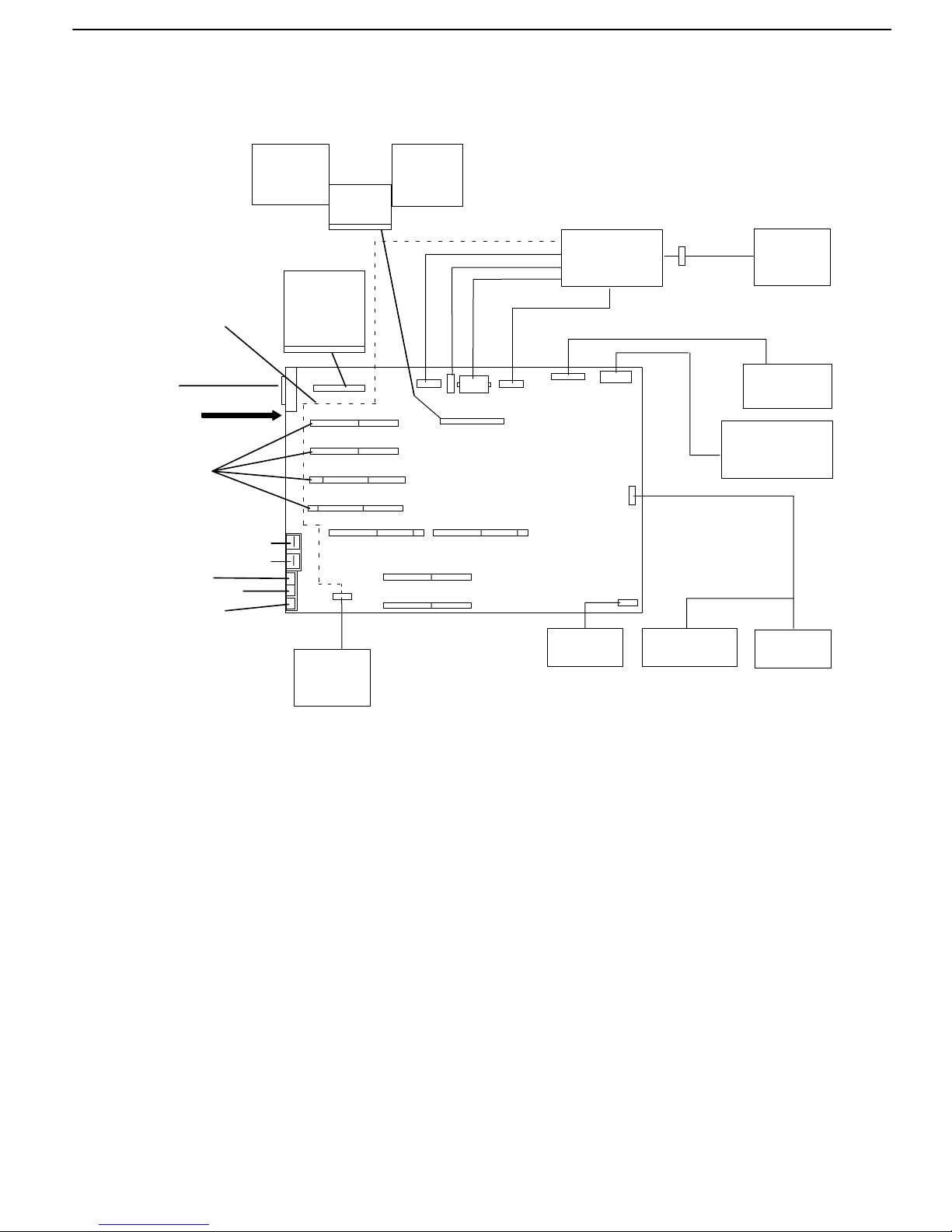
Data and Power Flow
Bus-Attached Disk Drives, Models 320, 32E, and 32H
Rear Fan Jumper
Cable – may be
present on some
systems.
Parallel
Port
Rear of
System Unit
Four I/O
Slots
Serial Port 1 (S1)
Serial Port 2 (S2)
Tablet (T)
Keyboard (K)
Mouse (M)
Disk
Drive
External
Diskette
Adapter
Card
Riser
Card
Disk
Drive
Power
Supply
Front
Fan
Diskette
3-Digit
Display
Rear
Fan
(Use optional
cable, if provided.)
Battery
Key Mode
Switch
Reset
Button
1-10 Installation and Service Guide
Page 22
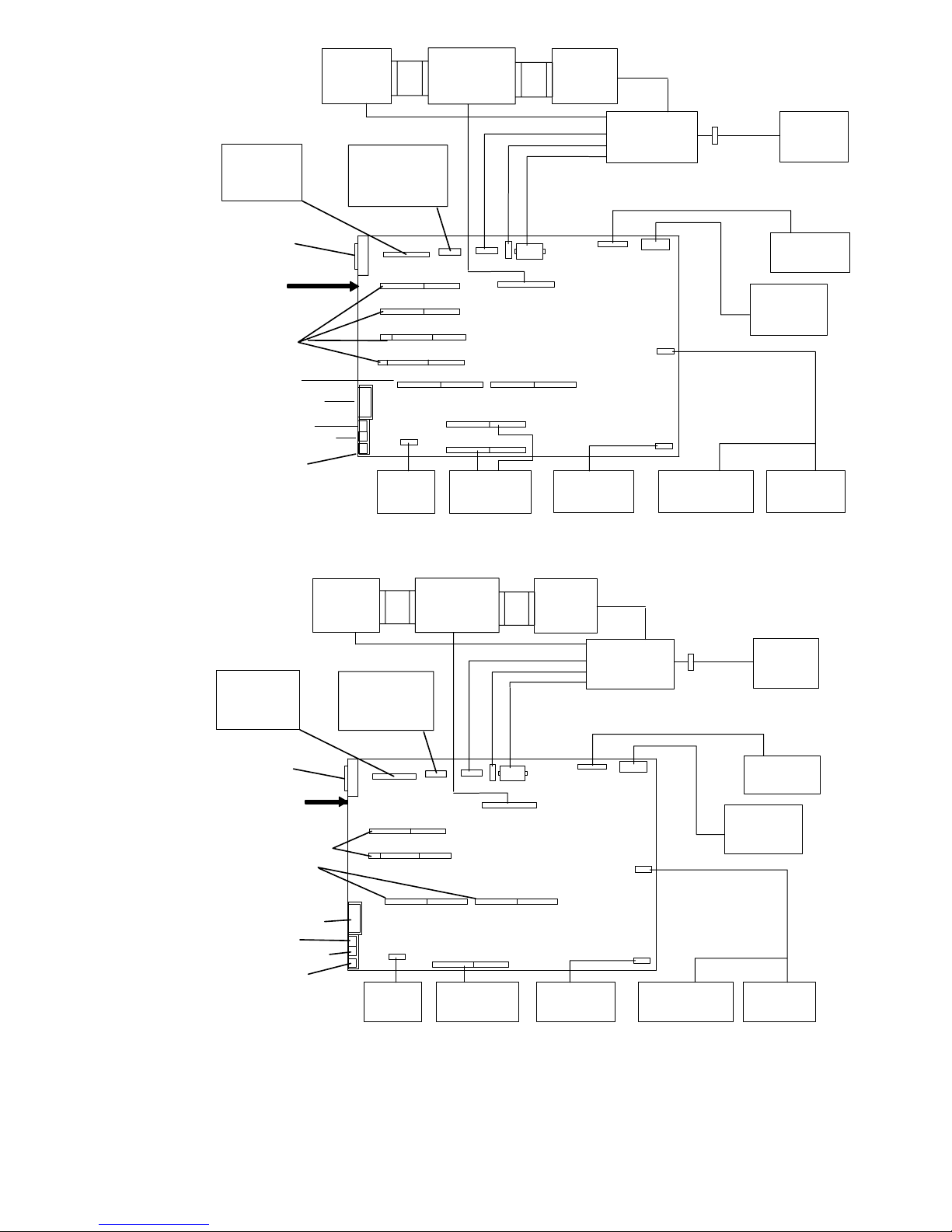
SCSI-Attached Disk Drives, Models 340, 34H, 350, 360/36T, 370/37T
Ethernet
Riser
Card
External
SCSI
Rear of
System Unit
Four I/O
Slots
CPU Card
Parallel Port
Tablet (T)
Keyboard (K)
Mouse (M)
Disk
Drive
Serial Port
Extender
Cable
Rear
Fan
SCSI Bus
Extension
Card
Memory
Cards
Disk
Drive
Battery
Power
Supply
Key Mode
Switch
Front
Fan
Diskette
3-Digit
Display
Reset
Button
SCSI-Attached Disk Drives, Models 355, 365, 375
Rear
Fan
SCSI Bus
Extension
Card
Memory
Card
Disk
Drive
Power
Supply
Battery
Ethernet
Riser
Card
External
SCSI
Rear of
System Unit
Two I/O Slots
CPU Card
Parallel Port
Tablet (T)
Keyboard (K)
Mouse (M)
Disk
Drive
Serial Port
Extender
Cable
Key Mode
Switch
Front
Fan
Diskette
3-Digit
Display
Reset
Button
Reference Information 1-11
Page 23
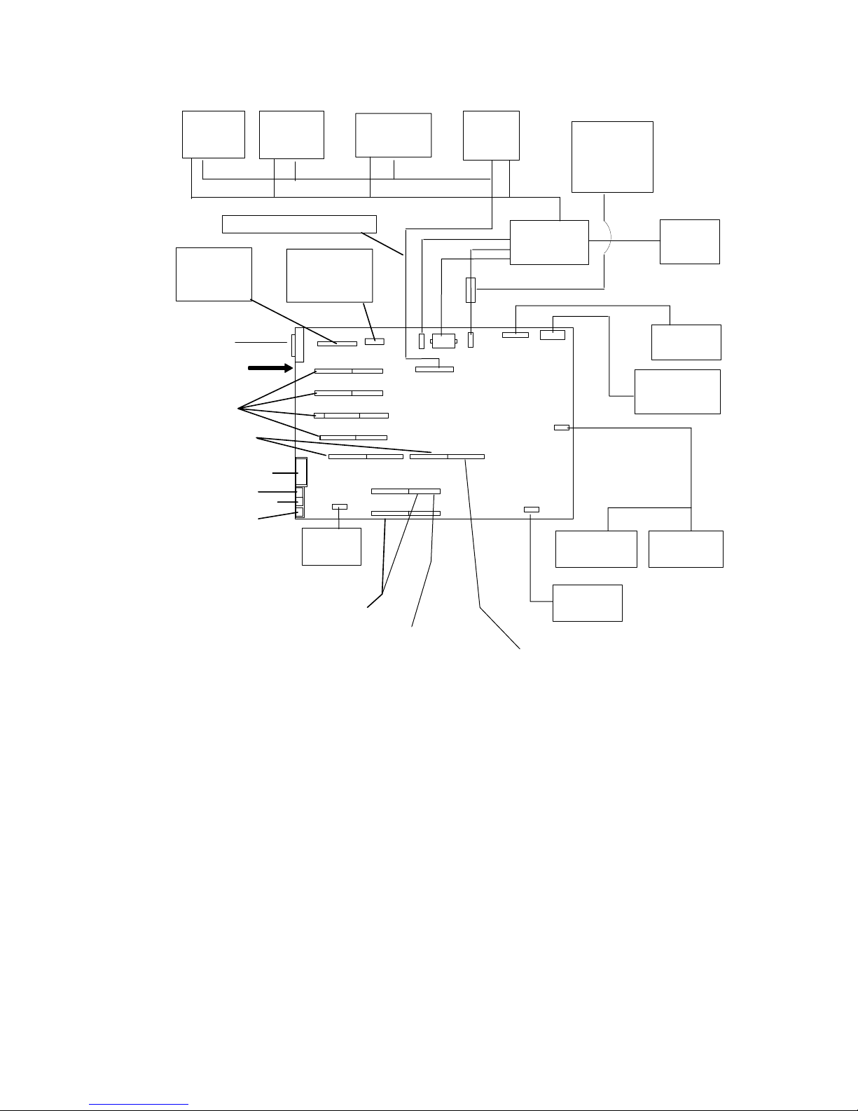
Data and Power Flow: SCSI Attached Disk Drives – Models 380, 390,
39H
Note: If external devices or cables are not connected to the external SCSI-2 connector, the
external SCSI-2 connector does not require a terminator.
Media
Drive
Ethernet
Riser
Card
External
SCSI-2
Rear of
System Unit
Four I/O
Slots
CPU Card
Parallel Port
Tablet (T)
Keyboard (K)
Mouse (M)
Media
Drive
Internal SCSI Cable
Serial Port
Extender
Cable
Rear
Fan
Disk
Drive
Disk
Drive
Power
Supply
Key Mode
Switch
Optional
Disk
Drive
Fan
Front
Fan
Diskette
3-Digit
Display
Reset
Button
Memory
Cards
Voltage Regulator
Card on Model 39H
Battery
Memory/CPU for
Model 39H
1-12 Installation and Service Guide
Page 24
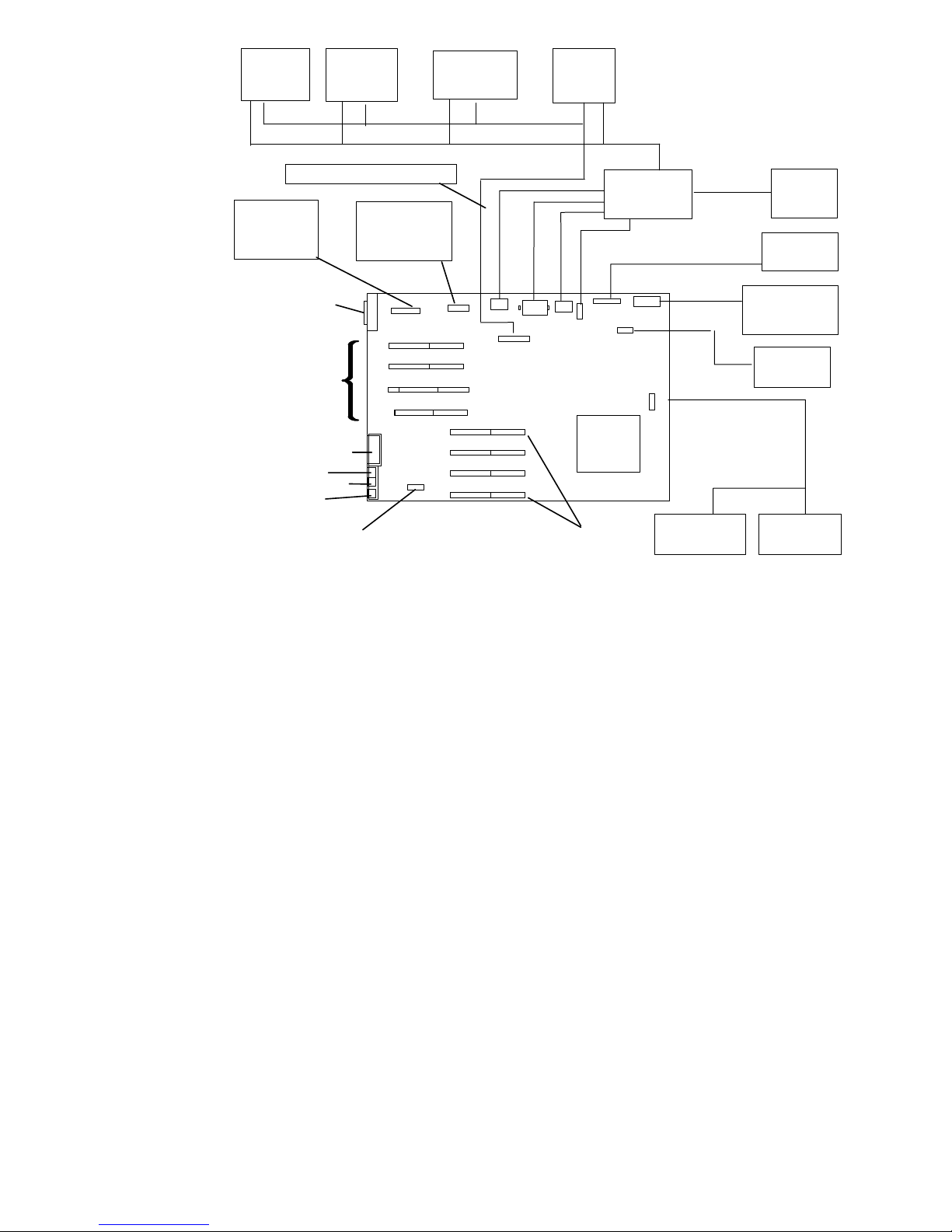
Data and Power Flow: SCSI Attached Disk Drives – Model 397
Media
Drive
Internal SCSI Cable
Ethernet
Riser
Card
SCSI-2
External
Rear of
System
Unit
Parallel Port
Tablet (T)
Keyboard (K)
Mouse (M)
I/O
Slots
Rear
Fan
Media
Drive
Serial Port
Extender
Cable
Disk
Drive
Disk
Drive
Memory
Cards
Power
Supply
Key Mode
Switch
Front
Fan
Diskette
3-Digit
Display
Battery
Reset
Button
Reference Information 1-13
Page 25

Specifications (all models except 380, 390, 39H, and 397)
Dimensions (Horizontal Position)
Height – 165 mm (6-1/2 inches) with foot
Depth – 525 mm (20-3/4 inches)
Width – 460 mm (18 inches)
Dimensions (Vertical Position)
Height – 470 mm (18-1/2 inches) with foot
Depth – 525 mm (20-3/4 inches)
Width – 280 mm (11-1/4 inches) at the foot
Weight (Maximum)
15.5 kg (34 pounds)
Operating Environment – Class B
Temperature – 16
Humidity – 8% to 80% noncondensing
Maximum Altitude – 2135 m (7000 feet)
Power Source Loading
0.7 k VA maximum
Power Supply
225 watts or 265 watts
Operating Voltage
100 V ac to 125 V ac; 50 Hz (Model 397)
200 V ac to 240 V ac; 60 Hz (Model 397)
Heat Output
1200 BTU per hour
° to 32° C (60° to 90° F)
1-14 Installation and Service Guide
Page 26

Specifications Models 380, 390, 39H, and 397
Dimensions (Horizontal Position)
Height: 162 mm (6.4 inches) with foot
Depth:
Width: 442 mm (17.4 inches)
Dimensions (Vertical Position)
Height: 454 mm (17.9 inches) with foot
Depth: 478 mm (18.8 inches)
Width: 241 mm (9.5 inches) at the foot
Weight (Maximum)
21.8 kg (48 pounds)
Operating Environment – Class B
Temperature: 16
Humidity: 8% to 80% noncondensing
Maximum Altitude: 2135 m (7000 feet)
Power Source Loading
0.7 k VA maximum
Power Supply
478 mm (18.8 inches)
° to 32° C (60° to 90° F)
275 watts
385 watts (Model 397)
Operating Voltage
100 V ac to 125 V ac; 50 Hz (Model 397)
200 V ac to 240 V ac; 60 Hz (Model 397)
Heat Output
1200 BTU per hour
Reference Information 1-15
Page 27

Power Cables
To avoid electrical shock, a power cable with a grounded attachment plug is provided. Use
only properly grounded outlets.
Power cables used in the U.S.A. and Canada are listed by Underwriter’s Laboratories (UL)
and certified by the Canadian Standards Association (CSA). These power cords consist of:
• Electrical cables, Type SVT or SJT.
• Attachment plugs complying with National Electrical Manufacturers Association (NEMA)
5-15P. That is:
“For 115 V operation, use a UL-listed cable set consisting of a minimum 18 AWG, Type
SVT or SJT three-conductor cord a maximum of 15 feet in length and a parallel blade,
grounding type attachment plug rated at 15 A, 125 V.”
“For 230 V operation in the U.S.A. use a UL-listed cable set consisting of a minimum 18
AWG, Type SVT or SJT three-conductor cable a maximum of 15 feet in length, and a
tandem blade, grounding type attachment plug rated at 15 A, 250 V.”
• Appliance couplers complying with International Electrotechnical Commission (IEC)
Standard 320, Sheet C13.
Power cables used in other countries consist of the following:
• Electrical cables, type HD21.
• Attachment plugs approved by the appropriate testing organization for the specific
countries where they are used.
“For units set at 230 V (outside U.S.A.): use a cable set consisting of a minimum 18 AWG
cable and grounding type attachment plug rated 15 A, 250 V. The cable set should have
the appropriate safety approvals for the country in which the equipment will be installed
and should be marked ‘HAR’.”
Refer to “Chapter 5. Parts Information” to find the power cables that are available.
1-16 Installation and Service Guide
Page 28
Service Inspection Guide
Perform a service inspection on the system when:
• The system is inspected for a maintenance agreement.
• Service is requested and service has not recently been performed.
• An alterations and attachments review is performed.
• Changes have been made to the equipment that may affect the safe operation of the
equipment.
• External devices that have their own power cable are added.
If the inspection indicates an unacceptable safety condition, the condition must be corrected
before servicing the machine.
Note: The correction of any unsafe condition is the responsibility of the owner of the
system.
Your system unit will resemble one of the following illustrations.
Do the following:
1. Check the covers (see the illustration) for sharp edges and for damage or alterations that
expose the internal parts of the system unit.
2. Check the covers for proper fit to the system unit. They should be in place and secure
with the screws tight.
Early Models
Top Cover
Serial Number
Front Cover
Key Mode
Switch
Reset Button
3-Digit Display
Diskette Drive
Diskette-Eject
Button
Power-On Light
Power Switch
Reference Information 1-17
Page 29
Models 380, 390, 39H, and 397
Top Cover
Front Cover
Key Lock
Reset Button
3-Digit Display
Power-On Light
Serial Number
Power Button
Diskette Drive
Diskette-Eject
Button
Optional
Media Bays
1-18 Installation and Service Guide
Page 30
3. If installed in the vertical position, ensure that the foot is securely attached and is stable.
4. Set the power switch of the system unit to Off.
5. Remove the covers.
6. Check for alterations or attachments. If there are any, check for obvious safety hazards
such as broken wires, sharp edges, or broken insulation.
7. Check the internal cables for damage.
8. Check for dirt, water, and any other contamination within the system unit.
9. Check the voltage label on the back of the system unit to ensure that it matches the
voltage at the outlet.
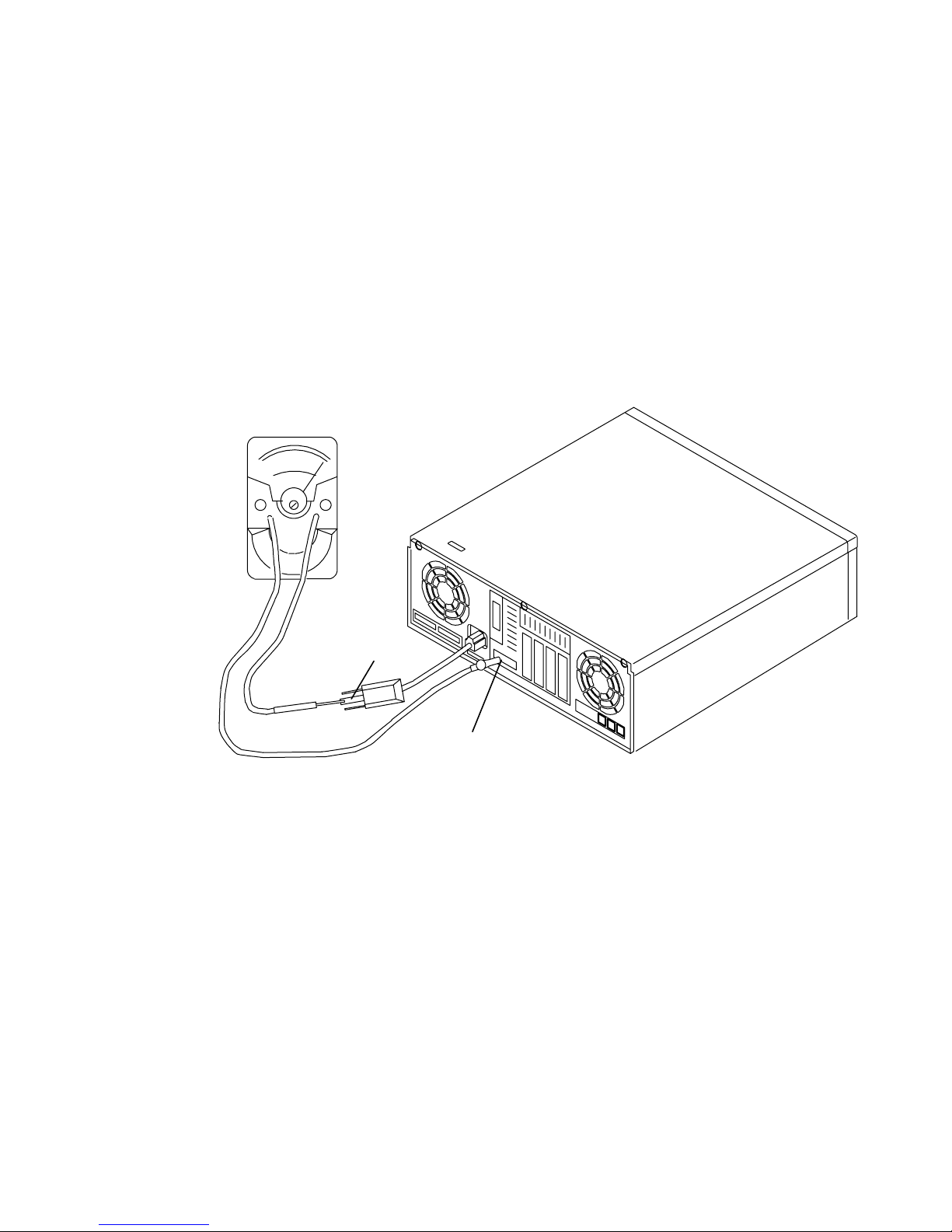
10. Check the external power cable for damage.
11. With the external power cable connected to the system unit, check for 0.1 ohm or less
resistance in this illustrationbetween the ground lug on the external power cable plug
and a jack screw on the parallel connector.
The following illustration is a typical representation of the rear view of a system unit.
Ground Lug
Jack Screw
12. If the system unit passes the test in the previous step, install the covers.
13. Check each external device that has its own power cable:
a. For damage to the power cord.
b. For the correct grounded power cable.
c. With the external power cable connected to the device, check for 0.1 ohm or less
resistance between the ground lug on the external power cable plug and the metal
frame of the device.
Reference Information 1-19
Page 31

Chapter 2. Maintenance Analysis Procedures (MAPS)
MAP 1520: 7012 Power MAP
Notes:
1. This is not a start of call MAP. Use this Power MAP only if you have been directed
here from a MAP step in the
Systems
2. All information in this MAP pertaining to 7012 Model 397 also applies to 7030
Model 397.
This procedure is used to locate power problems in the 7012. If a problem is detected, this
procedure helps you to isolate the problem to a failing field replaceable unit (FRU).
Observe the following safety notice during service procedures.
.
Diagnostic Information For Micro Channel Bus
Note: For a translation of this notice, see
DANGER
An electrical outlet that is not correctly wired could place hazardous voltage
on metal parts of the system or the products that attach to the system. It is
the responsibility of the customer to ensure that the outlet is correctly wired
and grounded to prevent an electrical shock.
Before installing or removing signal cables, ensure that the power cables for the
system unit and all attached devices are unplugged.
When adding or removing any additional devices to or from the system, ensure
that the power cables for those devices are unplugged before the signal cables
are connected. If possible, disconnect all power cables from the existing system
before you add a device.
Use one hand, when possible, to connect or disconnect signal cables to prevent
a possible shock from touching two surfaces with different electrical potentials.
During an electrical storm, do not connect cables for display stations, printers,
telephones, or station protectors for communication lines.
CAUTION:
This product is equipped with a three-wire power cable and plug for the user’s
safety. Use this power cable in conjunction with a properly grounded electrical outlet
to avoid electrical shock.
System Unit Safety Information
.
DANGER
To prevent shock hazard, disconnect the power cable from the electrical
outlet before relocating the system.
Maintenance Analysis Procedures (MAPs)
2-1520-1
Page 32

Step 1
Be sure that the external power cable to the system unit has continuity, is plugged into both
the system unit and the power outlet, and that the power outlet has been wired correctly
with the correct voltage
Did you find a problem?
NO Go to Step 2.
Step 2
(from Step 1)
YES Correct the problem. Go to “Map 0410: Repair Checkout” in the
Information For Micro Channel Bus Systems
1. Set the power switch on the system unit to Off.
2. Follow the procedure in “Top Cover Removal” on page 3-4.
Attention: P2 and P25 must be connected and disconnected at the same time.
3. Disconnect the P2 and P25 power supply connectors from the system planar.
4. Disconnect the power connectors P3 and P4 from the disk drives or from the system
planar.
5. Connect the power cable.
6. Set the power switch on the system unit to On. Wait 10 seconds before answering the
following question.
Did the power-on light come on and stay on, and are all the fans running
continuously?
.
Diagnostic
Step 3
(from Step 2)
NO Go to Step 3.
YES Go to Step 5.
Did the power-on light come on and go off?
NO Exchange the power supply. Refer to the “Power Supply” removal
procedure on page 3-16. Go to “Map 0410: Repair Checkout” in the
Diagnostic Information For Micro Channel Bus Systems
YES Go to Step 4.
.
2-1520-2
Installation and Service Guide
Page 33

Step 4
(from Step 3)
This problem can be caused by one of the following FRUs:
• Front fan
• Rear fan
Note: It is likely that the voltage regulator has failed when power is supplied and the power
light is on for one second or less. The same symptom will occur when the voltage
regulator is not connected to the CPU card.
• Voltage regulator card (Model 39H)
• System planar (Models 340, 34H, 350, 355, 360/36T, 365, 370/37T, and 375 , 380, 390,
397 if the rear fan is failing)
• Power supply.
The power supply will not stay on if it does not sense the rotation of the cooling fans.
Note: The power supply does not sense the fans that cool the disk drives if the fans have
only two wires and comes on independent of the operation of the front or rear fans.
These fans will not cause the power supply to shutdown.
When the front or rear fans are not connected or are not operating, the power supply
will usually power on for approximately three seconds before shutting down.
1. Set the power switch on the system unit to Off.
2. Test each fan by connecting a new fan. Refer to the “Rear Fan” removal procedure on
page 3-45 and the “Front Fan” removal procedure on page 3-46.
3. Set the power switch on the system unit to On. Wait 10 seconds before answering the
following question.
Did the power-on light come on and stay on?
NO Repeat this step until the defective fan is identified or all the fans have been
tested.
One of the remaining FRUs is defective.
To test each FRU, exchange the FRUs in the following order:
1. Voltage regulator card (Model 39H)
2. System planar (Models 340, 34H, 350, 355, 360/36T, 365, 370/37T,
375, 380, 390, and 397 if the rear fan is failing)
3. Power supply
If the symptom did not change and all the FRUs have been exchanged go
to Step 5.
YES Exchange the defective fan. Go to “Map 0410: Repair Checkout” in the
Diagnostic Information For Micro Channel Bus Systems
.
Maintenance Analysis Procedures (MAPs)
2-1520-3
Page 34

Step 5
(from Steps 2 and 4)
1. Set the power switch on the system unit to Off.
2. Connect the power supply connectors P2 and P25 to the system planar.
3. Set the power switch on the system unit to On. Wait 10 seconds before answering the
Did the power-on light come on and stay on?
NO Go to Step 6.
YES Go to Step 9.
Step 6
(from Step 5)
1. Set the power switch on the system unit to Off.
2. Disconnect the diskette drive cable P20 from the system planar.
Attention: P2 and P25 must be connected and disconnected at the same time.
following question.
Step 7
(from Step 6)
3. Set the power switch on the system unit to On. Wait 10 seconds before answering the
following question.
Did the power-on light come on and stay on?
NO Go to Step 7.
YES Exchange the diskette drive. Go to “Map 0410: Repair Checkout” in the
Diagnostic Information For Micro Channel Bus Systems
1. Set the power switch on the system unit to Off.
2. Disconnect and remove the disk drive frame from the system planar.
3. Set the power switch on the system unit to On. Wait 10 seconds before answering the
following question.
Did the power-on light come on and stay on?
NO Go to Step 11.
YES Go to Step 8.
.
2-1520-4
Installation and Service Guide
Page 35

Step 8
(from Step 7)
1. Set the power switch on the system unit to Off.
2. Disconnect and remove the front disk drive from the frame.
3. Install the disk drive frame in the system planar.
4. For Models 320, 32E, and 32H with SCSI-attached rear disk drive, connect the data
cable to the disk drive and the SCSI adapter on the system planar.
5. Set the power switch on the system unit to On. Wait 10 seconds before answering the
following question.
Did the power-on light come on and stay on?
NO One of the remaining FRUs is defective.
To test each FRU, exchange the FRUs in the following order:
1. Rear disk Drive
2. Data cable (Models 320, 32E, and 32H with SCSI-attached disk drives)
3. Riser card (Models 320, 32E, and 32H with bus-attached disk drives)
4. SCSI bus extender card (Models 340, 34H, 350, 355, 360/36T, 365,
370/37T ,375, 380, 390, 39H, and 397)
5. System planar (Models 340, 34H, 350, 355, 360/36T, 365, 370/37T,
375, 380, 390, 39H, 397 and models 320, 32E, and 32H with
bus-attached disk drives)
If the symptom did not change and all the FRUs have been exchanged go
to Step 11.
YES Exchange the front disk drive. Go to “Map 0410: Repair Checkout” in the
Diagnostic Information For Micro Channel Bus Systems
.
Maintenance Analysis Procedures (MAPs)
2-1520-5
Page 36

Step 9
(from Step 5)
Step 10
(from Step 9)
1. Set the power switch on the system unit to Off.
2. For Models 340, 34H, 350, 355, 360/36T, 365, 370/37T, and 375, 380, 390, 39H, 397,
and models 320, 32E, and 32H with SCSI-attached disk drives, connect power
connector P3 to the rear disk drive.
For Models 320, 32E, and 32H with bus-attached disk drives, connect power connector
P3 to the system planar.
3. Set the power switch on the system unit to On. Wait 10 seconds before answering the
following question.
Did the power-on light come on and stay on?
NO Exchange the rear disk drive. Go to “Map 0410: Repair Checkout” in the
Diagnostic Information For Micro Channel Bus Systems
YES Go to Step 10.
.
1. Set the power switch on the system unit to Off.
2. For Models 340, 34H, 350, 355, 360/36T, 365, 370/37T, and 375, 380, 390, 39H, 397,
and models 320, 32E, and 32H with SCSI-attached disk drives,connect power
connector P4 to the front disk drive.
For Models 320, 32E, and 32H with bus-attached disk drives, connect power connector
P4 to the system planar.
3. Set the power switch on the system unit to On. Wait 10 seconds before answering the
following question.
Did the power-on light come on and stay on?
NO Exchange the front disk drive. Go to “Map 0410: Repair Checkout” in the
Diagnostic Information For Micro Channel Bus Systems
YES Go to Step 11.
.
2-1520-6
Installation and Service Guide
Page 37

Step 11
(from Steps 7, 8, and 10)
1. Set the power switch on the system unit to Off.
2. Remove one memory card at a time from the system planar. Refer to the “Memory Card”
removal procedure on page 3-37.
3. Be sure the power has been off at least 15 seconds.
4. Set the power switch on the system unit to On. Wait 10 seconds before answering the
following question.
Did the power-on light come on and stay on?
NO Repeat this step until the defective memory card is identified or all the
YES The last memory card that you removed is defective. Exchange the
Step 12
memory cards have been removed.
If all the memory cards have been removed, go to Step 12.
memory card. Go to “Map 0410: Repair Checkout” in the
Information For Micro Channel Bus Systems
.
Diagnostic
(from Step 11)
1. Set the power switch on the system unit to Off.
2. Remove the CPU card from the system planar.
3. Set the power switch on the system unit to On. Wait 10 seconds before answering the
following question.
Did the power-on light come on and stay on?
NO Go to Step 13.
YES Exchange the CPU card. Go to “Map 0410: Repair Checkout” in the
Diagnostic Information For Micro Channel Bus Systems
.
Maintenance Analysis Procedures (MAPs)
2-1520-7
Page 38

Step 13
(from Step 12)
Step 14
1. Set the power switch on the system unit to Off.
2. Record the slot numbers of the adapters, label and record the location of any cables
attached to the adapters.
3. Remove one of the adapters from the I/O planar. Refer to the “Adapters, Ethernet Riser
Card, External Diskette Riser Card” removal procedure on page 3-24.
4. Set the power switch on the system unit to On. Wait 10 seconds before answering the
following question.
Did the power-on light come on and stay on?
NO Repeat this step until the defective adapter is identified or all the adapters
have been removed.
If the symptom did not change and all the adapters have been removed go
to Step 20.
YES Go to Step 14.
(from Step 13)
Step 15
(from Step 14)
Look at the adapter that was removed.
Were there any cables attached to the adapter before it was removed?
NO Go to Step 15.
YES Go to Step 17.
Some adapters may have FRUs on them.
Does the failing adapter have any FRUs?
NO Exchange the failing adapter. Go to “Map 0410: Repair Checkout” in the
Diagnostic Information For Micro Channel Bus Systems
YES Go to Step 16.
.
2-1520-8
Installation and Service Guide
Page 39

Step 16
(from Step 15)
Step 17
(from Step 14)
1. Set the power switch on the system unit to Off.
2. Remove the FRUs on the adapter.
3. Replace the failing adapter.
4. Set the power switch on the system unit to On. Wait 10 seconds before answering the
following question.
Did the power-on light come on and stay on?
NO Exchange the failing adapter. Go to “Map 0410: Repair Checkout” in the
Diagnostic Information For Micro Channel Bus Systems
YES One of the FRUs you removed from the adapter is failing. If only one FRU
was removed, exchange it. Otherwise, replace the FRUs, one at a time,
until you identify the failing FRU. Go to “Map 0410: Repair Checkout” in the
Diagnostic Information For Micro Channel Bus Systems
.
.
1. Set the power switch on the system unit to Off.
2. Replace the adapter without connecting any cables to it.
3. Set the power switch on the system unit to On. Wait 10 seconds before answering the
following question.
Did the power-on light come on and stay on?
NO Exchange the adapter. Go to “Map 0410: Repair Checkout” in the
Diagnostic Information For Micro Channel Bus Systems
YES Go to Step 18.
.
Maintenance Analysis Procedures (MAPs)
2-1520-9
Page 40

Step 18
(from Step 17)
Step 19
(from Step 18)
1. Set the power switch on the system unit to Off.
2. Connect one of the cables that was removed to the adapter.
3. Set the power switch on the system unit to On. Wait 10 seconds before answering the
following question.
Did the power-on light come on and stay on?
NO If the cable is removable from the attached device, go to Step 19.
If the cable cannot be removed from the attached device, exchange or
repair the device. Go to “Map 0410: Repair Checkout” in the
Information For Micro Channel Bus Systems
YES Repeat this step until the defective cable is identified or all the cables are
connected. Go to “Map 0410: Repair Checkout” in the
Information For Micro Channel Bus Systems
.
.
Diagnostic
Diagnostic
Step 20
(from Step 13)
1. Set the power switch on the system unit to Off.
2. Disconnect the cable from the attached device.
3. Set the power switch on the system unit to On. Wait 10 seconds before answering the
following question.
Did the power-on light come on and stay on?
NO Exchange the cable. Go to “Map 0410: Repair Checkout” in the
Information For Micro Channel Bus Systems
YES Exchange or repair the device. Go to “Map 0410: Repair Checkout” in the
Diagnostic Information For Micro Channel Bus Systems
1. Set the power switch on the system unit to Off.
2. Disconnect the key mode/reset switch connector P22 from the system planar.
3. Set the power switch on the system unit to On. Wait 10 seconds before answering the
following question.
.
.
Diagnostic
Did the power-on light come on and stay on?
NO Go to Step 21.
YES Exchange the key mode/reset switch. Go to “Map 0410: Repair Checkout”
in the
2-1520-10
Installation and Service Guide
Diagnostic Information For Micro Channel Bus Systems
.
Page 41

Step 21
(from Step 20)
Step 22
(from Step 21)
1. Set the power switch on the system unit to Off.
2. Disconnect the three-digit display connector P23 from the system planar.
3. Set the power switch on the system unit to On. Wait 10 seconds before answering the
following question.
Did the power-on light come on and stay on?
NO Go to Step 22.
YES Exchange the three-digit display. Go to “Map 0410: Repair Checkout” in the
Diagnostic Information For Micro Channel Bus Systems
1. Set the power switch on the system unit to Off.
2. Record the locations of all external cables; then disconnect the cables that are plugged
into connectors S1, S2, P, K, T, and M on the rear of the system unit.
.
Step 23
(from Step 22)
3. Set the power switch on the system unit to On. Wait 10 seconds before answering the
following question.
Did the power-on light come on and stay on?
NO For Models 340, 34H, 350, 355, 360/36T, 365, 370/37T, and 375, 380, 390,
39H, and 397 go to Step 23.
For Models 320, 32E, and 32H, exchange the system planar. Go to “Map
0410: Repair Checkout” in the
Bus Systems
YES Go to Step 24.
1. Set the power switch on the system unit to Off.
2. Disconnect connector P16 from the system planar.
3. Set the power switch on the system unit to On. Wait 10 seconds before answering the
following question.
Did the power-on light come on and stay on?
.
Diagnostic Information For Micro Channel
NO Exchange the system planar. Go to “Map 0410: Repair Checkout” in the
YES Exchange the serial port flex cable. Go to “Map 0410: Repair Checkout” in
Diagnostic Information For Micro Channel Bus Systems
the
Diagnostic Information For Micro Channel Bus Systems
Maintenance Analysis Procedures (MAPs)
.
.
2-1520-11
Page 42

Step 24
(from Step 22)
Step 25
(from Step 24)
1. Set the power switch on the system unit to Off.
2. Connect one of the cables that was removed.
3. Set the power switch on the system unit to On. Wait 10 seconds before answering the
following question.
Did the power-on light come on and stay on?
NO If the cable is removable from the attached device, go to Step 25.
If the cable cannot be removed from the attached device, exchange or
repair the device. Go to “Map 0410: Repair Checkout” in the
Information For Micro Channel Bus Systems
YES Repeat this step until all the cables are connected. Go to “Map 0410:
Repair Checkout” in the
Systems
.
Diagnostic Information For Micro Channel Bus
.
Diagnostic
1. Set the power switch on the system unit to Off.
2. Disconnect the cable from the attached device.
3. Set the power switch on the system unit to On. Wait 10 seconds before answering the
following question.
Did the power-on light come on and stay on?
NO Exchange the cable. Go to “Map 0410: Repair Checkout” in the
Information For Micro Channel Bus Systems
YES Exchange or repair the device. Go to “Map 0410: Repair Checkout” in the
Diagnostic Information For Micro Channel Bus Systems
.
.
Diagnostic
2-1520-12
Installation and Service Guide
Page 43

MAP 1540: 7012 Minimum Machine Configuration
Notes:
1. This is not a start of call MAP. You should use these MAPs only if you have been
directed here from a MAP step in the
Common Diagnostics and Service Guide.
2. All information in this MAP pertaining to 7012 Model 397 also applies to 7030
Model 397.
This MAP is used to locate defective FRUs not found by normal diagnostics. For this
procedure, diagnostics are run on a minimum-configured system. If a failure is detected on
the minimum-configured system, the remaining FRUs are exchanged one at a time until the
failing FRU is identified. If a failure is not detected, FRUs are added back until the failure
occurs. The failure is then isolated to the failing FRU.
The MAP steps on the following pages instruct you to reduce the system to one or more of
the following configurations:
POWERstation and POWERserver
Note: Refer to “Reading Flashing 888 Numbers” in the
Channel Bus Systems
On the Model 39H, the memory SIMMs are located on the CPU card. Memory must
be installed in pairs and the amount of memory installed on the CPU card must be
equal to the amount of memory installed on the memory card.
• System planar, CPU card (Model 39H without memory SIMMs), key mode/reset switch,
voltage regulator card (Model 39H), and the three-digit display panel.
If no failure is detected, a 213 or the flashing 888 sequence “888-103-12X-X43” (X can
be any number) is displayed in the three-digit display. Any other response means one of
the remaining FRUs is failing.
• System planar, CPU card, key mode/reset switch, the three-digit display panel, and
memory cards.
If no failure is detected, two or more numbers between 221 and 296 alternate in the
three-digit display or a solid 262 will be displayed (see page in the Supplement). Any
other response means one of the remaining FRUs is failing.
• System planar, CPU card, key mode/reset switch, the three-digit display panel, memory
cards, diskette drive, and a terminal attached to a serial port or a keyboard, display, and
graphics adapter.
If no failure is detected, the Operating Instructions frame is displayed when the
diagnostics are loaded and the system console is selected. Any other response means
one of the remaining FRUs is failing.
for information about reading flashing 888 sequences.
Diagnostic Information For Micro
Maintenance Analysis Procedures 2-1540-1
Page 44

Step 1
(from Steps 3, 7, 8, 9, and 14)
1. Ensure that the diagnostics and the operating system are shut down.
2. Turn the key mode switch to the Service position.
3. Set the power switch on the system unit to Off.
4. Insert the first diagnostic diskette into the diskette drive.
5. Set the power switch on the system unit to On.
6. Find the symptom in the following table that best matches the symptom on your system,
and then perform the associated task.
Information in
three-digit dis-
play
Nothing Diagnostic Operating Screen is displayed Go to Step 14.
c07 The diskette drive “In-Use” light is on Insert the next diagnostic
Other conditions Do this:
diskette.
Wait for one of the other
symptoms in this table to
occur.
888 flashing Go to Step 2.
Two or more num-
bers between 221
and 296 are displayed alternately.
c31 Instructions to select the system console
c05 The diskette drive “In-Use” light is on The diagnostic diskette is
299 or less Digits on solid for more than 3 minutes,
300 or greater Digits on solid for more than 3 minutes,
570 Digits on solid for more than 3 minutes,
First diagnostic diskette is loaded Go to Step 7.
Follow the instructions on
displayed on the screen.
and the power light is on.
and the power light is on.
and the power light is on.
the screen. Wait for one of
the other symptoms in this
table to occur.
probably bad. Insert the
same diskette from a du-
plicate diagnostic set. If
the duplicate diskette
causes the same symp-
tom, Go to Step 7.
Go to Step 2.
Go to Step 7.
Down level SCSI-2 code.
Run diagnostics with re-
movable media.
Any symptom not listed above. Go to Step 2.
2-1540-2 Installation and Service Guide
Page 45

Step 2
(from Steps 1 and 16)
1. Set the power switch on the system unit to Off.
2. Record the slot numbers of the Micro Channel adapters, label and record the location of
any cables attached to the adapters. Remove all the adapters from the system planar.
3. Record the slot numbers of the memory cards and then remove all the memory cards
from the system planar. If the system is a Model 39H, remove all memory SIMMs from
the CPU card.
4. Remove the L2 cache SIMM, if installed, from the CPU card.
5. Disconnect and remove the disk drive frame and disk drives.
6. Disconnect the diskette drive connector P20 from the system planar.
7. For Models 320, 32E, and 32H, remove the external diskette drive riser card (if installed).
For Models 340, 34H, 350, 355, 360/36T, 365, 370/37T, and 375 380, 390, 39H, and
397 remove the serial port extender cable connector P16 and the Ethernet riser card
from the system planar. Disconnect any external SCSI devices or the terminator from the
external SCSI connector.
8. Disconnect any cables that are plugged into connectors S1, S2, P, K, T, and M on the
rear of the system unit.
9. Set the power switch on the system unit to On.
10.Wait for one of the following conditions to occur:
• The system stops for at least three minutes and a constant number, character, or
symbol is displayed in the three-digit display and the power light is on.
• The system stops and a flashing 888 is displayed in the three-digit display.
• The power light does not come on, or the power light comes on but does not stay on.
Is a 213 or the flashing 888 sequence 888-103-12X-X43 (X can be any number)
displayed in the three-digit display?
NO Go to Step 3.
YES Go to Step 4.
Maintenance Analysis Procedures 2-1540-3
Page 46

Step 3
(from Step 2)
One of the FRUs remaining in the system unit is defective.
To test each FRU, exchange the FRUs in the following order:
1. CPU card
2. L2 cache SIMM if removed from CPU card.
3. System planar
4. Key mode/reset switch assembly
5. Three-digit display
6. Power supply.
The system is working correctly if it stops and the number 213 or the flashing 888 sequence
888-103-12X-X43 (X can be any number) is displayed in the three-digit display. If this
occurs, the last FRU you exchanged is defective.
1. Set the power switch on the system unit to Off.
2. Install one memory card. If the system is a Model 39H, install the removed memory
SIMMs on the CPU card. Verify that all SIMMs installed on the CPU card are the same
size.
3. Set the power switch on the system unit to On.
Is a 213 or the flashing 888 sequence 888-103-12X-X43 (X can be any number)
displayed in the three-digit display?
NO Reinstall the original FRU.
Repeat this step until the defective FRU is identified or all the FRUs have
been exchanged.
If the symptom did not change and all the FRUs have been exchanged, call
your service support person for assistance.
If the symptom has changed, check for loose cards, cables, and obvious
problems. If you do not find a problem, return to Step 1 in this MAP and
follow the instructions for the new symptom.
YES Go to “Map 0410: Repair Checkout” in the
POWERstation and
POWERserver Common Diagnostics and Service Guide.
2-1540-4 Installation and Service Guide
Page 47

Step 4
(from Step 2)
No failure was detected with this configuration.
1. Set the power switch on the system unit to Off.
2. Install one memory card.
For Models 340, 34H, 350, 355, 360/36T, 365, 370/37T, and 375, 380, 390, 39H, and 397,
disconnect the signal and power connectors from all the disk drives and plug the disk drive
frame into the system planar. Install the SCSI terminator on the external SCSI connector if it
was previously removed.
1. Set the power switch on the system unit to On.
2. Wait for one of the following conditions to occur:
• The system stops and two or more numbers with values between 221 and 296 are
displayed alternately in the three-digit display.
• For Models 340, 34H, 350, 355, 360/36T, 365, 370/37T, and 375, 380, 390, 39H, and
397, the system stops with a value of 243 for up to six minutes and then changes to to a
value of 262.
• The system stops for at least three minutes and a constant number, character, or symbol
is displayed in the three-digit display and the power light is on.
• The system stops and a flashing 888 is displayed in the three-digit display.
• The power light does not come on, or the power light comes on but does not stay on.
Did the system stop and are two or more numbers between the values of 221 and
296 displayed alternately in the three-digit display or, is the number 262 displayed
in the three–digit display?
NO Go to Step 5.
YES Repeat this step until the defective memory card is identified or all the
memory cards are installed and tested.
After all memory is installed and tested, set the power switch on the system
unit to Off.
Connect the signal cable for the 3.5-inch diskette drive P20 to the system
planar. Go to Step 7, substep 6.
Maintenance Analysis Procedures 2-1540-5
Page 48

Step 5
(from Step 4)
The failure may be caused by a defective SIMM on the last memory card installed. To
isolate the failing SIMM in a pair of SIMMs, do the following:
1. Set the power switch on the system unit to Off. Using a pair of operational SIMMs for the
type of memory card used, install the pair of SIMMs in locations 1 and 2 on one of the
suspected memory cards.
2. Set the power switch on the system unit to On. If operational, the system will stop and
two or more numbers with values between 221 and 296 are displayed alternately in the
three-digit display, or a solid 262 will be displayed.
• For Models 340, 34H, 350, 355, 360/36T, 365, 370/37T, and 375, 380, 390, 39H, and
397, the system stops with a value of 243 for up to six minutes and then changes to to a
value of 262.
3. If the system still fails, continue testing the SIMMs in pairs (locations 3 and 4, 5 and 6, 7
and 8) until the system does not fail, or all the SIMMs on the suspected memory cards
have been tested.
Were you able to isolate the failed pair of SIMMs?
NO Exchange the memory card. If this does not correct the problem, go to Step
6.
YES Go to “Map 0410: Repair Checkout” in the
POWERserver Common Diagnostics and Service Guide.
POWERstation and
2-1540-6 Installation and Service Guide
Page 49

Step 6
(from Step 5)
One of the FRUs remaining in the system unit is defective.
To test each FRU, exchange the FRUs in the following order:
1. System planar
2. CPU card (if a Model 39H, memory SIMMs must be installed)
3. Voltage regulator card (Model 39H)
4. Power supply.
The system is working correctly if it stops and two or more numbers between 221 and 296
are displayed in the three-digit display or a solid 262 is displayed. If this occurs, the last
FRU you exchanged is defective.
For Models 340, 34H, 350, 355, 360/36T, 365, 370/37T, and 375, 380, 390, 39H, and 397,
the system stops with a value of 243 for up to six minutes and then changes to to a value of
262.
1. Set the power switch on the system unit to Off.
2. Exchange one of the FRUs in the list.
3. Set the power switch on the system unit to On.
Did the system stop and are two or more numbers between the values of 221 and
296 displayed alternately in the three-digit display or is the number 262 displayed in
the three-digit display?
NO Reinstall the original FRU.
Repeat this step until the defective FRU is identified or all the FRUs have
been exchanged.
If the symptom did not change and all the FRUs have been exchanged, call
your service support person for assistance.
If the symptom has changed, check for loose cards, cables, and obvious
problems. If you do not find a problem, return to Step 1 in this MAP and
follow the instructions for the new symptom.
YES Go to “Map 0410: Repair Checkout” in the
POWERstation and
POWERserver Common Diagnostics and Service Guide.
Maintenance Analysis Procedures 2-1540-7
Page 50

Step 7
(from Steps 1 and 4)
1. Set the power switch on the system unit to Off.
2. Record the slot numbers of the Micro Channel adapters, label and record the location of
3. Disconnect and remove the disk drive frame and disk drives.
4. For Models 320, 32E, and 32H, remove the external diskette drive riser card (if installed).
5. Disconnect any cables that are plugged into connectors S1, S2, P, K, T, and M on the
6. Insert the first diagnostic diskette into the diskette drive.
7. Set the power switch on the system unit to On.
8. Wait for one of the following conditions to occur:
any cables attached to the adapters. Remove all the adapters from the I/O planar.
For all other Models, remove the serial port extender cable connector P16 and the
Ethernet riser card from the system planar.
rear of the system unit.
• The 3.5-inch diskette drive in-use light is on and c05 or c07 is displayed in the
three-digit display.
• The system stops for at least three minutes and a constant number, character, or
symbol is displayed in the three-digit display and the power light is on.
• The system stops and two or more numbers with values between 221 and 296 are
displayed alternately in the three-digit display.
• The system stops and a flashing 888 is displayed in the three-digit display
• The power light does not come on, or the power light comes on but does not stay on.
Is the 3.5-inch diskette drive in-use light on and c07 displayed in the three-digit
display.
NO One of the FRUs remaining in the system unit is defective.
In the following order, exchange the FRUs that have not been exchanged:
1. Diskette drive
2. Diskette drive signal cable
3. Key mode/reset switch assembly
4. System planar
5. CPU card
6. Voltage regulator card (Model 39H)
7. Power supply.
Repeat this step until the defective FRU is identified or all the FRUs have
been exchanged.
If the symptom did not change and all the FRUs have been exchanged, call
your service support person for assistance.
If the symptom has changed check for loose cards, cables, and obvious
problems. If you do not find a problem, return to Step 1 in this MAP and
follow the instructions for the new symptom.
YES Go to Step 8.
2-1540-8 Installation and Service Guide
Page 51

Step 8
(from Step 7)
1. Set the power switch on the system unit to Off.
2. Install and connect the disk drive frame and disk drives.
3. For Models 320, 32E, and 32H with SCSI-attached disk drives, install the SCSI adapter
in the I/O planar and reconnect the signal cable to the SCSI adapter.
4. For Models 320, 32E, and 32H with SCSI-attached disk drives, and Models 340, 34H,
350, 355, 360/36T, 365, 370/37T, and 375, 380, 390, 39H, and 397, disconnect the
signal and power connectors from all the disk drives.
For Models 320, 32E, and 32H with bus-attached disk drives, disconnect the power
connectors P3 and P4 from the system planar.
5. Insert the first diagnostic diskette into the diskette drive.
6. Set the power switch on the system unit to On.
7. Wait for one of the following conditions to occur:
• The 3.5-inch diskette drive in-use light is on and c05 or c07 is displayed in the
three-digit display.
• The system stops for at least three minutes and a constant number, character, or
symbol is displayed in the three-digit display and the power light is on.
• The system stops and two or more numbers with values between 221 and 296 are
displayed alternately in the three-digit display.
• The system stops and a flashing 888 is displayed in the three-digit display.
• The power light does not come on, or the power light comes on but does not stay on.
Is the 3.5-inch diskette drive in-use light on and c07 displayed in the three-digit
display.
NO One of the FRUs remaining in the system unit is defective.
In the following order, exchange the FRUs that have not been exchanged:
• For Models 320, 32E, and 32H with bus-attached or SCSI-attached disk
drives:
1. Rear disk drive (if bus-attached)
2. Front disk drive (if bus-attached)
3. Riser card (if present)
4. SCSI adapter (if present)
Note: Refer to
Diagnostics and Service Guide
Blowing”.
POWERstation and POWERserver Common
, “ SCSI-1 Adapter Fuse
5. SCSI cable (if present)
6. SCSI terminator
7. System planar
8. Power supply.
Maintenance Analysis Procedures 2-1540-9
Page 52

• For Models 340, 34H, 350, 355, 360/36T, 365, 370/37T, 375, 380, 390,
39H, and 397:
1. SCSI bus extender card
Step 9
Note: Refer to
2. SCSI cable
3. SCSI terminator
4. System planar
5. Power supply.
Repeat this step until the defective FRU is identified or all the FRUs have
been exchanged.
If the symptom did not change and all the FRUs have been exchanged, call
your service support person for assistance.
If the symptom has changed, check for loose cards, cables, and obvious
problems. If you do not find a problem, return to Step 1 in this MAP and
follow the instructions for the new symptom.
YES Go to Step 9.
POWERstation and POWERserver Common
Diagnostics and Service Guide
Fuse Blowing and PTC Tripping.
, Chapter One; SCSI-1 Adapter
(from Step 8)
1. Set the power switch on the system unit to Off.
2. Connect the signal and power connectors for the disk drives one at a time. Start with the
connectors for the drive that contains the bootable operating system software.
3. Remove any diskette from the diskette drive.
4. Set the power switch on the system unit to On.
5. Wait for one of the following conditions to occur:
• The three-digit display is blank.
• The system stops and c31 is displayed in the three-digit display.
• The system stops for at least three minutes and a constant number, character, or
symbol is displayed in the three-digit display and the power light is on.
• The system stops and two or more numbers with values between 221 and 296 are
displayed alternately in the three-digit display.
• The system stops and a flashing 888 is displayed in the three-digit display.
• The power light does not come on, or the power light comes on but does not stay on.
Is c31 displayed in the three-digit display or is the three-digit display blank?
NO The last SCSI device that you connected is defective.
Exchange the defective device.
Repeat this step until the signal and power connectors for all the disk drives
have been connected.
2-1540-10 Installation and Service Guide
Page 53

If the symptom did not change and all the disk drives have been
exchanged, in the following order exchange the FRUs that have not been
exchanged:
• For Models 320, 32E, and 32H with bus-attached or SCSI-attached disk
drives:
1. Riser card (if present)
2. SCSI adapter (if present)
Note: Refer to
Diagnostics and Service Guide
POWERstation and POWERserver Common
, Chapter One; SCSI-1 Adapter
Fuse Blowing.
3. SCSI cable (if present)
4. System planar
5. Power supply.
• For Models 340, 34H, 350, 355, 360/36T, 365, 370/37T, and 375,380,
390, 39H, and 397:
1. SCSI bus extender card
Note: Refer to
Diagnostics and Service Guide
POWERstation and POWERserver Common
, Chapter One; Integrated
SCSI Fuse Blowing .
2. SCSI cable
3. System planar
4. Voltage regulator card (Model 39H)
5. Power supply.
If the symptom did not change and all the FRUs have been exchanged, call
your service support person for assistance.
If the symptom has changed, check for loose cards, cables, and obvious
problems. If you do not find a problem, return to Step 1 in this MAP and
follow the instructions for the new symptom.
YES Repeat this step until the signal and power connectors for all the disk drives
have been connected.
For Models 320, 32E, and 32H, go to Step 11.
For Models 340, 34H, 350, 355, 360/36T, 365, 370/37T, and 375, 380, 390,
39H, and 397, go to Step 10.
Maintenance Analysis Procedures 2-1540-11
Page 54

Step 10
(from Step 9)
1. Set the power switch on the system unit to Off.
2. Connect the serial port extender cable P16 to the system planar.
3. Insert the first diagnostic diskette into the diskette drive.
4. Set the power switch on the system unit to On.
5. Wait for one of the following conditions to occur:
• The 3.5-inch diskette drive in-use light is on and c05 or c07 is displayed in the
three-digit display.
• The system stops and c31 is displayed in the three-digit display.
• The system stops for at least three minutes and a constant number, character, or
symbol other than c31 is displayed in the three-digit display and the power light is on.
• The system stops and two or more numbers with values between 221 and 296 are
displayed alternately in the three-digit display.
• The system stops and a flashing 888 is displayed in the three-digit display.
• The power light does not come on, or the power light comes on but does not stay on.
Is c07 or c31 displayed in the three-digit display or is the three-digit display blank?
NO Exchange the serial port extender cable. Go to “Map 0410: Repair
Checkout” in the
and Service Guide.
YES Go to Step 11.
POWERstation and POWERserver Common Diagnostics
2-1540-12 Installation and Service Guide
Page 55

Step 11
(from Steps 9 and 10)
1. Set the power switch on the system unit to Off.
2. Connect the cables that were plugged into connectors S1, S2, P, K, T, and M on the rear
of the system unit.
3. Insert the first diagnostic diskette into the diskette drive.
4. Set the power switch on the system unit to On.
5. Wait for one of the following conditions to occur:
• The DIAGNOSTIC OPERATING INSTRUCTIONS screen is displayed.
• The system stops and c31 is displayed in the three-digit display.
• The 3.5-inch diskette drive in-use light is on and c07 is displayed in the three-digit
• The system stops for at least three minutes and a constant number, character, or
• The system stops and two or more numbers with values between 221 and 296 are
display. Insert the next diagnostic diskette. Continue this substep until all diskettes are
loaded, c31 is displayed in the three-digit display, or the DIAGNOSTICS OPERATING
INSTRUCTIONS screen is displayed.
symbol other than c31 is displayed in the three-digit display and the power light is on.
displayed alternately in thethree-digit display.
• The system stops and a flashing 888 is displayed in the three-digit display.
• The power light does not come on, or the power light comes on but does not stay on.
Is the DIAGNOSTIC OPERATING INSTRUCTIONS screen displayed or is c31
displayed in the three-digit display?
NO Go to the Problem Determination procedures (test procedures) for the
devices attached to the SIO ports and test those devices. If a problem is
found, follow the procedures for correcting the problem on that device.
YES Go to Step 12.
Maintenance Analysis Procedures 2-1540-13
Page 56

Step 12
(from Step 11)
The system is working correctly with this configuration. One of the FRUs (adapters) that you
removed is probably defective.
1. Set the power switch on the system unit to Off.
2. Install a FRU (adapter) and connect any cables and devices that were attached to it.
3. Insert the first diagnostic diskette into the diskette drive.
4. Set the power switch on the system unit to On.
5. Wait for one of the following conditions to occur:
• The DIAGNOSTIC OPERATING INSTRUCTIONS screen is displayed.
• The system stops and c31 is displayed in the three-digit display.
• The 3.5-inch diskette drive in-use light is on and c07 is displayed in the three-digit
display. Insert the next diagnostic diskette. Continue this substep until all diskettes are
loaded or c31 is displayed in the three-digit display.
• The system stops for at least three minutes and a constant number, character, or
symbol other than c31 is displayed in the three-digit display and the power light is on.
• The system stops and two or more numbers with values between 221 and 296 are
displayed alternately in the three-digit display.
• The system stops and a flashing 888 is displayed in the three-digit display.
• The power light does not come on, or the power light comes on but does not stay on.
Is the DIAGNOSTIC OPERATING INSTRUCTIONS screen displayed or is c31
displayed in the three-digit display?
NO Go to Step 13.
YES Repeat this step until all of the FRUs (adapters) are installed.
Go to “Map 0410: Repair Checkout” in the
POWERstation and
POWERserver Common Diagnostics and Service Guide.
2-1540-14 Installation and Service Guide
Page 57

Step 13
(from Step 12)
1. Set the power switch on the system unit to Off.
2. Starting with the devices, disconnect a device or cable connector from the last adapter
installed.
3. Insert the first diagnostic diskette into the diskette drive.
4. Set the power switch on the system unit to On.
5. Wait for one of the following conditions to occur:
• The DIAGNOSTIC OPERATING INSTRUCTIONS screen is displayed.
• The system stops and c31 is displayed in the three-digit display.
• The 3.5-inch diskette drive in-use light is on and c07 is displayed in the three-digit
display. Insert the next diagnostic diskette. Continue this substep until all diskettes are
loaded or c31 is displayed in the three-digit display.
• The system stops for at least three minutes and a constant number, character, or
symbol other than c31 is displayed in the three-digit display and the power light is on.
• The system stops and two or more numbers with values between 221 and 296 are
displayed alternately in the three-digit display.
• The system stops and a flashing 888 is displayed in the three-digit display.
• The power light does not come on, or the power light comes on but does not stay on.
Is the DIAGNOSTIC OPERATING INSTRUCTIONS screen displayed or is c31
displayed in the three-digit display?
NO Repeat this step until the defective device or cable is identified or all the
devices and cables have been disconnected.
One of the FRUs remaining in the system unit is defective.
To test each FRU, exchange the FRUs in the following order:
1. Adapter (last one installed)
2. System planar
3. CPU card
4. Voltage regulator card (Model 39H)
5. Power supply.
If the symptom did not change and all the FRUs have been exchanged, call
your service support person for assistance.
If the symptom has changed, check for loose cards, cables, and obvious
problems. If you do not find a problem, return to Step 1 in this MAP and
follow the instructions for the new symptom.
YES The last device or cable you disconnected is defective.
Exchange the defective device or cable.
Go to “Map 0410: Repair Checkout” in the
POWERstation and
POWERserver Common Diagnostics and Service Guide.
Maintenance Analysis Procedures 2-1540-15
Page 58

Step 14
(from Step 1)
1. Set the power switch on the system unit to Off.
2. Record the slot numbers of the adapters, label and record the location of any cables
attached to the adapters. Remove all the adapters from the system planar except the
display adapter (if installed and the attached display will be the system console).
3. Disconnect any cables that are plugged into connectors S1, S2, P, K, T, and M on the
rear of the system unit.
Note: If a terminal attached to S1 or S2 will be the system console, do not disconnect it.
If a display attached to a display adapter will be the system console, do not disconnect
the keyboard.
4. Insert the first diagnostic diskette into the diskette drive.
5. Set the power switch on the system unit to On.
6. Wait for one of the following conditions to occur:
• The DIAGNOSTIC OPERATING INSTRUCTIONS screen is displayed
• The system stops and c31 is displayed in the three-digit display. Follow the
instructions on the display to select your console display.
• The 3.5-inch diskette drive in-use light is on and c07 is displayed in the three-digit
display. Insert the next diagnostic diskette. Continue this substep until all diskettes are
loaded, c31 is displayed in the three-digit display, or the DIAGNOSTICS OPERATING
INSTRUCTIONS screen is displayed.
• The system stops for at least 3 minutes and a constant number, character, or symbol
other than c31 is displayed in the three-digit display and the power light is on.
• The system stops and two or more numbers with values between 221 and 296 are
displayed alternately in the three-digit display.
• The system stops and a flashing 888 is displayed in the three-digit display.
• The power light does not come on, or the power light comes on but does not stay on.
Is the DIAGNOSTIC OPERATING INSTRUCTIONS screen displayed?
NO The symptom has changed. Check for loose cards, cables, and obvious
problems. If you do not find a problem, return to Step 1 in this MAP and
follow the instructions for the new symptom.
YES Go to Step 15.
2-1540-16 Installation and Service Guide
Page 59

Step 15
(from Step 14)
Step 16
1. Press the Enter key.
2. If the terminal type has not been defined, you must use the Initialize Terminal option on
the FUNCTION SELECTION menu to initialize the AIX operating system environment
before you can continue with the diagnostics. This is a separate and different operation
than selecting the console display.
3. Select Advanced Diagnostics Routines.
4. When the DIAGNOSTIC MODE SELECTION menu displays, select System Verification.
5. Select System Checkout.
Did you get an SRN?
NO One of the adapters or devices you removed is causing the problem. Install
the adapters and devices one at a time to determine the failing adapter or
device. Test the system after each adapter or device is installed.
YES Go to Step 16.
(from Step 15)
Look at the FRU part numbers associated with the SRN.
Have you exchanged all the FRUs that correspond to the failing function codes?
NO Exchange the FRU with the highest failure percentage that has not been
changed.
Repeat this step until all the FRUs associated with the SRN have been
replaced or System Checkout runs with no trouble found. Run System
Checkout after each FRU is exchanged.
Go to “Map 0410: Repair Checkout” in the
POWERserver Common Diagnostics and Service Guide.
YES Go to Step 2.
POWERstation and
Maintenance Analysis Procedures 2-1540-17
Page 60

Chapter 3. Removal and Replacement Procedures
All information in these procedures pertaining to 7012 Model 397 also applies to 7030 Model
397.
Observe the following safety notice during service procedures.
Note: For a translation of this notice, see
DANGER
An electrical outlet that is not correctly wired could place hazardous voltage
on metal parts of the system or the products that attach to the system. It is
the responsibility of the customer to ensure that the outlet is correctly wired
and grounded to prevent an electrical shock.
Before installing or removing signal cables, ensure that the power cables for the
system unit and all attached devices are unplugged.
When adding or removing any additional devices to or from the system, ensure
that the power cables for those devices are unplugged before the signal cables
are connected. If possible, disconnect all power cables from the existing system
before you add a device.
Use one hand, when possible, to connect or disconnect signal cables to prevent a
possible shock from touching two surfaces with different electrical potentials.
During an electrical storm, do not connect cables for display stations, printers,
telephones, or station protectors for communication lines.
CAUTION:
This product is equipped with a three-wire power cable and plug for the user’s safety.
Use this power cable in conjunction with a properly grounded electrical outlet to
avoid electrical shock.
System Unit Safety Information
.
DANGER
To prevent shock hazard, disconnect the power cable from the electrical outlet
before relocating the system.
Removal and Replacement Procedures 3-1
Page 61

Handling Static-Sensitive Devices
Attention: Adapters, planars, diskette drives, and disk drives are sensitive to static
electricity discharge. These devices are wrapped in antistatic bags, as shown in this
illustration, to prevent this damage.
Take the following precautions:
• Do not remove the device from the antistatic bag until you are ready to install the device
in the system unit.
• If you have an antistatic wrist strap available, use it while handling the device.
• With the device still in its antistatic bag, touch it to a metal frame of the system.
• Grasp cards and boards by the edges. Hold drives by the frame. Avoid touching the
solder joints or pins.
• If you need to lay the device down while it is out of the antistatic bag, lay it on the
antistatic bag. Before you pick it up again, touch the antistatic bag and the metal frame of
the system at the same time.
• Handle the devices carefully in order to prevent permanent damage.
3-2 Installation and Service Guide
Antistatic Bag
Page 62

Rear Cover
Note: Not all models have rear covers. If your model has a rear cover, use the following
Removal
1. Grab the lower-right and lower-left corners and tilt the bottom of the rear cover out about
2. Pull the rear cover off.
Rear Cover
procedure for removal and replacement.
30 degrees. The cover retainers are located at the lower outside edges.
Replacement
1. Attach the top edge of the rear cover.
2. Rotate the bottom of the rear cover to the front and push it into place.
1
2
Removal and Replacement Procedures 3-3
Page 63

Top Cover
Removal
Note: If the machine is normally operated in the vertical position, it may be helpful to
remove the base and proceed with the machine in the horizontal position.
1. Set the power switches of the attached devices to Off.
2. Set the power switch of the system unit to Off.
3. Disconnect the power cable.
4. Set the key mode switch to the Service position. This unlocks the top cover for removal.
5. If your system unit has a rear cover, do the removal procedure in “Rear Cover” on page
3-3.
6. Loosen the top cover screws.
Attention: On models 340 and 350, be careful not to damage the contact strip on the right
of the power supply.
7. If your system unit has handles, use the handles to slide the top cover to the rear and lift
it off.
Attention: Do not operate the system unit with the covers removed. Operating with covers
on ensures adequate cooling of the components.
The following illustration is a rear view representation of a system unit.
Top Cover Screws
Handles
Replacement
1. Depending on your system unit model, either align the holes at the rear of the top cover
with the two pins on the frame; or, place the top cover on the base with the front tab in
the slot
2. Slide the cover to the front. Ensure that the front lip seats; and depending on your
system unit model, the rear hooks are seated under the rear lip.
3-4 Installation and Service Guide
Page 64

3. Tighten the top cover screws.
4. Set the key mode switch back to its normal position.
5. If your system unit has a rear cover, do the replacement procedure in “Rear Cover” on
page 3-3.
6. Connect the power cable.
7. Set the power switches of the attached devices to On.
8. Set the power switch of the system unit to On.
The following illustration is a rear view representation of a system unit.
Top Cover Screws
Handles
Removal and Replacement Procedures 3-5
Page 65

Front Cover
Removal
1. Set the power switches of the attached devices to Off.
2. Set the power switch of the system unit to Off.
3. Disconnect the power cable.
4. Set the key mode switch to the Service position.
5. Remove the key from the key mode switch.
6. Remove media from the diskette drive.
7. If your system unit has a rear cover, do the removal procedure in “Rear Cover” on page
8. Do the “Top Cover” removal procedure on page 3-4.
9. Lift the latch/latches to unhook the cover.
10.Depending on your system unit, rotate the top of the front cover forward about 45
11. On some system units, the cover can be placed at the front of the machine without
3-3.
degrees and pull forward or, pivot the left side of the front cover outward and remove.
disconnecting the key lock and mode switch cable (P22).
Attention: Do not operate the system unit with the covers removed. Operating with the
covers on ensures adequate cooling of the components.
Your system unit will resemble one of the following illustrations.
Except for Models 380,
390, 39H, and 397
Latches
1
2
Latch
1
Models 380, 390,
39H, and 397
3-6 Installation and Service Guide
Page 66

Replacement
1. Depending on your system unit model, align and insert the tabs at the bottom, or, insert
2. Depending on your system unit model, rotate the top of the front cover into place, or,
3. Depending on your system unit mode, push the latches into their closed positions;
4. Do the “Top Cover” replacement procedure on page 3-4.
5. If your system unit model has a rear cover, do the replacement procedure in “Rear
6. Connect the power cable.
7. Replace the key in the key mode switch and turn it to the Normal position.
8. Set the power switches of the attached devices to On.
9. Set the power switches of the system unit to On.
the tabs at the right side of the front cover.
pivot the left side of the front cover into place.
or,snap the cover into position.
Cover” on page 3-3.
Removal and Replacement Procedures 3-7
Page 67

Disk Drive (Bus-Attached): Models 320, 32E, 32H
Note: A system may have two bus-attached, or two SCSI-attached, or a combination of
one SCSI and one bus-attached drive. For models 320, 32E, and 32H
SCSI-attached drives, see page 3-10.
Note: Refer to “Handling Static-Sensitive Devices” on page 3-2 before removing or
installing adapters in this system.
Removal
1. Set the power switches of the attached devices to Off.
2. Set the power switch of the system unit to Off.
3. Unplug the power cable.
4. Do the removal procedure in “Rear Cover” on page 3-3.
5. Do the removal procedure in “Top Cover” on page 3-4
Note: If one of the drives is a SCSI-attached drive, remove the power cable from the SCSI
drive.
6. Pull the frame latch forward.
7. Lift the frame assembly out.
8. Remove the four screws from the disk drive.
9. Remove the disk drive by carefully unplugging it from the riser card, using a side-to-side
motion.
10. Slide the riser card out.
Latch
Frame Assembly
Riser Card
Disk Drives
3-8 Installation and Service Guide
Page 68

Replacement
Attention: If you move the disk drive from a colder or warmer environment than the room
where it will be used, allow the disk drive to gradually reach the temperature of the room. By
allowing the disk drive time to acclimate, data loss or permanent damage to the disk drive
can be avoided. The proper time is at least one hour for each 10°C (18°F) of difference
between the storage environment and the operating environment.
1. Slide the riser card into the guides in the disk drive frame.
2. Using a side-to-side motion, carefully plug the disk drive into the riser card.
3. Install the four screws into the disk drive.
4. Ensure that the power supply connectors P3 and P4 are connected into J3 and J4 on the
Note: If the frame contains a combination of one SCSI and one bus-attached drives, either
5. If a SCSI drive is present, route the SCSI signal cable under the rear drive.
6. Install the frame assembly and push the latch to its closed position.
7. Do the replacement procedure in “Top Cover” on page 3-4.
planar.
P3 or P4 are attached to the SCSI drive instead of J3 or J4 on the planar. Also, the
cable from the SCSI drive must be attached to the SCSI I/O controller.
8. Do the replacement procedure in “Rear Cover” on page 3-3.
9. Plug in the power cable.
10. Set the power switches of the attached devices to On.
11. Set the power switch of the system unit to On.
Removal and Replacement Procedures 3-9
Page 69

Disk Drive (SCSI-Attached): Models 320, 32E, 32H
Reference to the Small Computer Systems Interface (SCSI) Input/Output controller is
abbreviated as SCSI I/O controller in this publication.
Note: A system may have two SCSI-attached, two bus-attached, or a combination of one
SCSI and one bus-attached drive. For the bus-attached drive, see page 3-8.
Note: Refer to “Handling Static-Sensitive Devices” on page 3-2 before removing or
installing adapters in this system.
Removal
1. Set the power switches of the attached devices to Off.
2. Set the power switch of the system unit to Off.
3. Unplug the power cable.
4. Do the removal procedure in “Rear Cover” on page 3-3.
5. Do the removal procedure in “Top Cover” on page 3-4.
6. Remove the cable from the SCSI adapter card. Leave the other end attached to the drive
or drives.
7. If a front drive is installed, disconnect the power supply connector (P4) from the front
drive or drives.
8. Pull the frame latch forward.
9. If a drive is installed in the rear position, partially pull the frame up and disconnect the
power supply connector (P3) from the rear drive.
10. Remove the frame assembly.
11. Remove the SCSI cable from the disk drive.
12. Remove the disk drive from the frame (four screws in each drive).
Frame
Assembly
P3
Latch
P4
Disk Drives
SCSI
Cable
3-10 Installation and Service Guide
Page 70

Replacement
Attention: If you move the disk drive from a colder or warmer environment than the room
where it will be used, allow the disk drive to gradually reach the temperature of the room. By
allowing the disk drive time to acclimate, data loss or permanent damage to the disk drive
can be avoided. The proper time is at least one hour for each 10°C (18°F) of difference
between the storage environment and the operating environment.
1. Set the address settings of the new disk drive the same as the settings of the old drive.
2. Install the disk drive in the frame.
3. Connect the cable to the drive or drives. Ensure that the keys on the connectors match.
Note: If you have only one drive, plug the power supply connector (P3 or P4) for the empty
4. Plug in the power supply connector (P3) to the rear drive and install the frame assembly.
5. Ensure that the latch is in its closed position.
6. Connect the cable to the SCSI card.
For more information, refer to Chapter 9 of
Bus Systems
The cable must be routed under the disk drive frame assembly.
position into the appropriate planar connector. For specific locations, refer to the
“System Planar Location Connector” figures starting on page 1-5.
.
Diagnostic Information For Micro Channel
7. Plug in the power supply connector (P4) to the front drive.
8. Do the replacement procedure in “Top Cover” on page 3-4.
9. Do the replacement procedure in “Rear Cover” on page 3-3.
10. Plug in the power cable.
11. Set the power switches of the attached devices to On.
12. Set the power switch of the system unit to On.
Removal and Replacement Procedures 3-11
Page 71

Disk Drive (SCSI-Attached): Models 340, 34H, 350, 355, 360/36T,
365, 370/37T, 375
Reference to the Small Computer Systems Interface (SCSI) Input/Output controller is
abbreviated as SCSI I/O controller in this publication.
Note: Refer to “Handling Static-Sensitive Devices” on page 3-2 before removing or
installing drives in this system.
Removal
1. Set the power switches of the attached devices to Off.
2. Set the power switch of the system unit to Off.
3. Disconnect the power cable.
4. Do the removal procedure in “Rear Cover” on page 3-3.
5. Do the removal procedure in “Top Cover” on page 3-4.
6. If a front drive is installed, disconnect the power supply connector (P4) from the front
drive.
7. Pull the frame latch forward.
8. If a drive is installed in the rear position, partially pull the frame up and disconnect the
power supply connector (P3) from the rear drive.
9. Remove the frame assembly.
10. Using the pull loops, remove the SCSI cables from the disk drives.
11. Remove the disk drive from the frame (four screws in each drive).
12. Remove the two screws from the riser card.
13. Slide the riser card out.
LatchFrame
Assembly
P4P3
SCSI
Cable
Disk
Drives
3-12 Installation and Service Guide
Page 72

Replacement
Attention: If you move the disk drive from a colder or warmer environment than the room
where it will be used, allow the disk drive to gradually reach the temperature of the room. By
allowing the disk drive time to aacclimate, data loss or permanent damage to the disk drive
can be avoided. The proper time is at least one hour for each 10°C (18°F) of difference
between the storage environment and the operating environment.
1. Slide the riser card into the guides in the frame assembly.
2. Replace the two screws for the riser card.
3. Set the address settings of the new disk drive the same as the settings of the old drive.
4. Install the disk drive in the frame.
5. Connect the cable or cables between the drive and the bus extender card. Ensure that
Note: If you have only one disk drive, plug the power supply connector for the empty
6. Plug in the power supply connector (P3) to the rear drive and install the frame assembly.
For more information, refer to Chapter 9 of
Bus Systems
the keys on the connectors match.
position into its planar connector. For locations, see “Data and Power Flow” in
Chapter 1.
.
Diagnostic Information For Micro Channel
7. Ensure that the latch is in its closed position.
8. Plug in the power supply connector (P4) to the front disk drive.
9. Do the replacement procedure in “Top Cover” on page 3-4.
10. Do the replacement procedure in “Rear Cover” on page 3-3.
11. Plug in the power cable.
12. Set the power switches of the attached devices to On.
13. Set the power switch of the system unit to On.
Removal and Replacement Procedures 3-13
Page 73

Disk Drive: Models 380, 390, 39H, and 397
References to the small computer systems interface (SCSI) input/output controller is
abbreviated as SCSI I/O controller in this publication.
Note: Refer to “Handling Static-Sensitive Devices” on page 3-1.
Removal
14.Set the power switches of the attached devices to Off.
15.Set the power switch of the system unit to Off.
16.Disconnect the power cable.
17.Do the “Top Cover” removal procedure on page 3-4.
18.Remove the shipping screw at the rear of the system unit. (The screw retains the disk
drive frame assembly during shipping, and can be discarded after system installation.)
19.Remove the frame assembly.
20.Disconnect the power supply connectors from the drives.
21.Disconnect the internal SCSI cable from the drives using the pull loops.
22.Remove the disk drive from the frame (four screws in each drive).
Models 380, 390, 39H
P3 (C)
HookFrame
Assembly
P4 (D)
Disk
Drives
SCSI
Cable
3-14 Installation and Service Guide
Page 74

Replacement
Attention: If you move the disk drive from a colder or warmer environment than the room
where it will be used, allow the disk drive to gradually reach the temperature of the room. By
allowing the disk drive time to acclimate, data loss or permanent damage to the disk drive
can be avoided. The proper time is at least one hour for each 10°C (18°F) of difference
between the storage environment and the operating environment.
1. Set the address settings of the new disk drive the same as the settings of the old drive.
2. Install the disk drive in the frame.
3. Connect the SCSI cable to the drives. Ensure that the keys on the connectors match.
4. Plug in the power supply connector to the drives.
5. Install the front of the frame assembly first. The lower front alignment tab must locate in
6. Then pivot the rear of the frame assembly into place. There are hooks and alignment
7. Do the “Top Cover” replacement procedure on page 3-4.
For more information, refer to Chapter 9 of
Bus Systems
its slot.
tabs in the front and rear.
.
Diagnostic Information For Micro Channel
8. Connect the power cable.
9. Set the power switches of the attached devices to On.
10. Set the power switch of the system unit to On.
Model 397
Assembly
P4 (D)
P3 (C)
SCSI
Cable
HookFrame
Disk
Drives
Removal and Replacement Procedures 3-15
Page 75

Power Supply
For Models 380, 390, 39H, and 397, refer to the procedure on page 3-18.
Removal
For a translation of the following notice, see
SA23-2652.
DANGER
Do not attempt to open the covers of the power supply. Power supplies are
not serviceable and are to be replaced as a unit.
1. Set the power switches of the attached devices to Off.
2. Set the power switches of the system unit to Off.
3. Remove the power cord from the electrical outlet first, then from the power supply.
4. Do the removal procedure in “Rear Cover” on page 3-3.
5. Do the removal procedure in “Top Cover” on page 3-4.
6. Do the removal procedure in “Front Cover” on page 3-6.
7. Do removal procedure in “Diskette Drive” on page 3-20.
8. Disconnect all power supply cables.
9. Remove the external diskette or Ethernet card.
System Unit Safety Information
, Order Number
10. Remove the ground strap screw at the planar.
11. Remove the power supply mounting screw.
Attention: On models 340 and 350, be careful not to damage the contact strip on the right
of the power supply.
12. Slide the power supply forward and out.
Front
Mounting
Screw
P26
(Front Fan)
P4 (Disk)
P2 (I/O Power Connector)
Aligning
Tabs
Ground Strap
3-16 Installation and Service Guide
P3 (Disk)
P25 (Power Control)
P27 (Rear Fan)
(May be present on
some systems.)
Page 76

Replacement
1. Ensure that the aligning tabs are not bent.
Attention: On later system units, those that have the slot under the power supply, be careful
not to bend the grounding fingers at the rear of the system unit when you install the power
supply.
2. Lay the power supply approximately 25 mm (one inch) in front of its installed position and
3. Install the power supply mounting screw.
4. Install the ground strap screw.
5. Install the external diskette or Ethernet riser card.
6. Connect the cables. For SCSI-attached drives, connect P3 and P4 directly to the drives.
Note: Ensure that P25 is properly connected to protect the memory cards.
7. Do the replacement procedure in “Diskette Drive” on page 3-20.
8. Do the replacement procedure in “Front Cover” on page 3-6.
9. Do the replacement procedure in “Top Cover” on page 3-4.
10. Do the replacement procedure in “Rear Cover” on page 3-3.
push it to the rear to engage the tabs with the slots at the rear of the system unit.
11. Plug the power cable into the power supply first, then plug it into the wall outlet.
12. Set the power switches of the attached devices to On.
13. Set the power switch of the system unit to On.
Removal and Replacement Procedures 3-17
Page 77

Power Supply (Models 380, 390, 39H, and 397)
Removal
For a translation of the following notice, see
SA23-2652.
DANGER
Do not attempt to open the covers of the power supply. The power supply is
not serviceable and is to be replaced as a unit.
14. Set the power switches of the attached devices to Off.
15. Set the power switch of the system unit to Off.
16. Unplug the power cord from the electrical outlet first, and then disconnect from the
power supply.
17. Do the “Top Cover” removal procedure on page 3-4.
18. Disconnect all power supply cables.
19. Loosen the power supply mounting screw at the front of the power supply unit.
20. Lift the front of the power supply slightly, and then slide it forward approximately 5mm
and then lift it out.
Models 380, 390, 39H
Front
System Unit Safety Information
P28
(Media)
P29
, order number
P3 (Disk)
P27 (Rear Fan)
P25
Power
Control
P30
(On/Off)
P26
(Front Fan)
P4 (Disk)
P2
I/O Power
Connector
3-18 Installation and Service Guide
Page 78

Replacement
1. Be sure that the aligning tabs on the base are not bent.
2. Place the power supply approximately 5 mm (one-quarter inch) in front of its installed
3. Push it to the rear to engage the tabs on the base with the slots on the power supply.
4. Tighten the power supply mounting screw.
5. Connect the cables.
Note: Ensure that the P25 connector is properly connected to protect the memory cards.
6. Do the “Top Cover” replacement procedure on page 3-4.
7. Connect the power cable into the power supply first, then plug it into the electrical outlet.
8. Set the power switches of the attached devices to On.
9. Set the power switch of the system unit to On.
position. The mounting screw should align with the keyway hole in the power supply.
Model 397
P3 (Power)
Front
P31 (Front Fan)
P26
(Front Fan)
P28
(Media)
P25
Power
Control
(Media)
P29
P30
(On/Off)
P27 (Power)
P5 (Disk)
P4 (Disk)
P2
I/O Power
Connector
Removal and Replacement Procedures 3-19
Page 79

Diskette Drive
Removal
1. Set the power switches of the attached devices to Off.
2. Set the power switches of the system unit to Off.
3. If the system unit model has a rear cover, do the Rear Cover removal procedure on
page 3-3.
4. Do the “Top Cover” removal procedure on page 3-4.
5. For all models, except 380, 390, 39H, and 397, do the Front Cover removal procedure on
page 3-6.
6. If the system unit is a model 380, 390, 39H, or 397, remove the screw on the left side of
the diskette drive plate. If there is also an optional disk drive fan installed, lay it on top of
the power supply. For all other models disconnect the diskette drive cable connector from
the planar (P20) and pull up on the latch.Remove the screw on the left side of the
diskette drive plate. If there is also an optional disk drive fan installed, lay it on top of the
power supply.
7. If the system unit is a model 380, 390, 39H, or 397, slide the diskette drive assembly
back and lift up; for all other models slide the drive assembly forward and pull up.
8. If the system unit is a model 380, 390, 39H, or 397, remove the four screws that hold the
diskette drive to the metal plate; for all other models, disconnect the cable from the
diskette drive.
Models 380, 390,
39H, and 397
Cable
3-20 Installation and Service Guide
Page 80

All other models
Replacement
1. If the system unit is a model 380, 390, 39H, or 397, mount the diskette drive on the metal
2. If the system unit is a model 380, 390, 39H, or 397, place the diskette drive in position
3. Push the drive back to its installed position.
4. If the system unit is a model 380, 390, 39H, or 397, connect the cable to the diskette
5. For all models, except 380, 390, 39H, and 397, do the Front Cover replacement
6. Do the Top Cover replacement procedure on page 3-4.
Latch
plate and screw into place. For all other models, place the cable under the drive
assembly and ensure that the cable does not interfere with the four tabs. Fold the cable
as shown.
and replace the screw on the left side of the diskette drive. If you have an optional DASD
fan installed, put it back into place on the diskette drive plate. For all other models, align
the four tabs on the drive with their holes on the power supply.
drive. For all other models push down on the latch, plug the diskette drive cable
connector labeled P20 into the connector labeled J20 on the planar, and plug the cable
connector labeled “Drive A” into the rear of the diskette drive.
procedure on page 3-6.
Cable
7. If your system unit moded has a rear cover, do the Rear Cover replacement procedure
on page3-3.
8. Set the power switches of the attached devices to On.
9. Set the power switches of the system unit to On.
Removal and Replacement Procedures 3-21
Page 81

Media Drive Removal for Models 380, 390, 39H, and 397
Notes:
Removal
1. For a translation of this notice, see
2. This caution only applies to the CD-ROM drive.
CAUTION:
A Class 3 laser is contained in the device. Do not attempt to operate the device while
it is disassembled. Do not attempt to open the covers of the device, as it is not
serviceable and is to be replaced as a unit.
1. Remove any media from the drive.
2. Set the power switches of the attached devices to Off.
3. Set the power switch of the system unit to Off.
4. Do the “Top Cover” removal procedure on page 3-4.
5. Do the “Front Cover” removal procedure on page 3-6.
6. Disconnect the power cable and SCSI connectors from the media devices.
7. Push the latch on the left inside of the metal cover housing to release the media drive
from the housing.
8. Slide the drive assembly out the front.
System Unit Safety Information
.
9. Record the address.
10.Remove the four rail screws to detach the drive assembly from the rails. Retain the
screws.
Rail
(Each Side)
3-22 Installation and Service Guide
Page 82

Replacement
1. Using the four rail screws, attach the drive assembly to the rails.
2. Set the address, matching the drive being replaced. For new installations, assign a SCSI
3. Push the drive into the media bay to the installed position.
4. Plug the cable connectors into the drive.
Attention: Some 4 mm tape drives can be misplugged. Visually align the drive connector
pins with the cable connector holes.
5. Do the “Front Cover” replacement procedure on page 3-6.
6. Do the “Top Cover” replacement procedure on page 3-4.
7. Set the power switches of the attached devices to On.
8. Set the power switch of the system unit to On.
address of 5 or 6.
Removal and Replacement Procedures 3-23
Page 83

Adapter Cards, Ethernet Riser Card, and External Diskette
Riser Card
Removal
Note: Refer to “Handling Static-Sensitive Devices” on page 3-2 before removing or
installing adapters in this system.
Facing the back of the system unit, there are four vertical adapter slots, and each slot is
covered with a bracket. Also, there is a special slot for an optional external diskette riser
card or Ethernet riser card. Each bracket is held in place by a knurled knob.
1. Set the power switches of the attached devices to Off.
2. Set the power switch of the system unit to Off and unplug the external power cable.
3. If the system unit has a rear cover, do the rear cover removal procedure on page 3-3.
4. Do the Top Cover removal procedure on page 3-4.
5. Note the location of the adapter.
6. Disconnect any attached device and internal cables from the adapter.
7. Loosen the knurled knob that holds the adapter card bracket.
8. If the adapter has a card extender that holds the front end of the adapter, release the
extender by pressing the locking tab to the side.
9. Grasp the adapter by the pull tabs and pull it out of the slot.
Locking Tab
Card Extender
Models 380, 390,
39H, and 397
Locking Tab
Card Extender
3-24 Installation and Service Guide
Page 84

Replacement
Note: If you are replacing the Ethernet riser card, ensure that the jumpers on the new card
Replace in the reverse order. When replacing the adapter, ensure that the plate of the
adapter bracket is under the knurled knob and is in contact with the card guide (for a
grounding path) at the top of the adapter bracket.
Note: To avoid having the Ethernet riser card short out against the cover, rock the card
are set the same as on the old card. Refer to “Setting the Ethernet Riser Card
Jumpers” on page 3-26.
toward the front of the machine.
Removal and Replacement Procedures 3-25
Page 85

Setting the Ethernet Riser Card Jumpers
Thick/Thin Ethernet Riser
Note: Follow the correct shutdown and power down procedure, and remove the Ethernet
riser card from the system unit.
The thick/thin Ethernet riser card comes shipped configured for the thin (BNC) Ethernet
interface. The configuration is set by two removable jumper blocks that fit over two of the
three rows of pins that are located on the riser card. Follow these steps to change the
configuration:
1. Pull each of the two jumper blocks off of the configuration jumper block.
2. Replace the two jumper blocks on the upper two rows of pins to configure for the thick
connector, or on the lower two rows for the thin connector.
Thick/Thin Ethernet Card Jumper Positions
Jumpers in “Thick” Position
Jumpers in “Thin” Position
Thick/Thin
Fuse
Jumpers
Thick Connector
Thin Connector
3-26 Installation and Service Guide
Page 86

Twisted-Pair Ethernet Riser
Note: Follow correct shutdown and power procedure and remove the Ethernet riser from
the system unit.
The twisted-pair Ethernet riser comes with a single jumper panel marked LINK with the
words ON and OFF on either side. This jumper is used to make the twisted-pair Ethernet
riser compatible with IEEE 802.3 10 base T Ethernet networks. The twisted-pair riser is
shipped with the jumper set to the ON position.
If the network is not 10 base T, move the LINK jumper to the OFF position.
Twisted Pair Ethernet Card Jumper Position
OFF
Empty Pin
LINK
Jumper
Link Integrity
Jumper
ON
LINK
Jumper
Empty Pin
Jumper in “Off” PositionJumper in “On” Position
ONOFF
Green LED
Indicator
Twisted-Pair
Connector
The single green LED on the twisted-pair riser lights when the riser is properly connected to
a 10 base T network and the power to the system unit is on. If the green LED does not
come on, there could be several possible problems. The twisted-pair cable is defective or
not connected, the network is not a 10 base T network, or the Ethernet riser card is not
properly installed in the system unit.
Removal and Replacement Procedures 3-27
Page 87

Attached Devices
For a translation of the following notices, see
SA23-2652.
DANGER
An electrical outlet that is not correctly wired could place hazardous voltage
on metal parts of the system or the devices that attach to the system. It is the
responsibility of the customer to ensure that the outlet is correctly wired and
grounded to prevent an electrical shock.
Before installing or removing signal cables, ensure that the power cables for the
system unit and all attached devices are unplugged.
When adding or removing any additional devices to or from the system, ensure
that the power cables for those devices are unplugged before the signal cables
are connected. If possible, disconnect all power cables from the existing system
before you add a device.
Use one hand, when possible, to connect or disconnect signal cables to prevent a
possible shock from touching two surfaces with different electrical potentials.
During an electrical storm, do not connect cables for display stations, printers,
telephones, or station protectors for communications lines.
CAUTION:
This product is equipped with a three-wire power cable and plug for the user’s safety.
Use this power cable in conjunction with a properly grounded electrical outlet to
avoid electrical shock.
System Unit Safety Information
, Order Number
3-28 Installation and Service Guide
Page 88

Removal
1. Set the power switches of all attached devices to Off.
2. Set the power switch of the system unit to Off and unplug the external cable.
3. Unplug the external power cables to the attached devices.
4. If the system unit has a rear cover, do the rear cover removal procedure on page 3-3.
5. Disconnect the device signal cable from the adapter.
6. If the device has one or more toroids, refer to “Toroids” on page 3-57.
Models 320, 32E, 32H (Later System Units):
External
Diskette
(Optional)
Power
Plate (not on all models)
Models 340, 34H,350, 355, 360/36T, 365, 370/37T, 375:
Ethernet
Power
Serial 1
Models 380, 390, 39H, and 397
Serial 2
Parallel Port
SCSI Port
Adapter Positions
1234
Adapter Positions
1234
Tablet
Keyboard
Mouse
Serial 1 Serial 2
T ablet
Keyboard
Mouse
Parallel Port
Ethernet
Power
Replacement
Replace in the reverse order.
S 1 S2
Tablet
P
1234
SCSI PortSerial 1 Serial 2
Adapter Positions
Removal and Replacement Procedures 3-29
Parallel Port
Keyboard
Mouse
Page 89

CPU Card
Removal
Note: Refer to “Handling Static-Sensitive Devices” on page 3-2 before removing or
installing the CPU card in this system. For Model 39H, refer to the “CPU Card for
Model 39H” removal procedure on page 3-31.
1. Set the power switches of the attached devices to Off.
2. Set the power switch of the system unit to Off.
3. If the system unit has a rear cover, do the rear cover removal procedure on page 3-3.
4. Do the Top Cover removal procedure on page 3-4.
5. On Models 340 and 350, remove the CPU shield.
6. Make a note of its position and remove the CPU card.
Note: For specific system planar connector locations refer to pages1-5 and 1-6.
1
2
3
4
Figure 2. System Planar Connector locations illustration.
Replacement
Reminder to Service Representative: After you exchange the CPU card, notify the
customer that the unique identification number of the system unit has changed. The
customer needs to update the authorization number for any program that uses the
identification number for access.
J14
J8
J6
J5
J1
J15
J7
J16
J13
J12
J11
J10
J9 J19
J18
J17
J27
J25
J2
B
C
J24
J20
A
J23
CPU Card
Connector
J22
J21
1. Align the CPU card with the front and rear card guides and the connector, and then press
the CPU card down into the connector.
2. Replace the CPU shield on Models 340 and 350.
3. Do the Top Cover replacement procedure on page 3-4.
4. If the system unit has a rear cover, do the rear cover replacement procedure on page
3-3.
5. Set the power switches of the attached devices to On.
6. Set the power switch of the system unit to On.
3-30 Installation and Service Guide
Page 90

CPU Card (Model 39H)
Note: Refer to “Handling Static-Sensitive Devices” before removing or installing the CPU
card in this system.
Removal
1. Set the power switches of the attached devices to Off.
2. Set the power switch of the system unit to Off.
3. Set the key mode switch to the Service position.
4. Remove the top cover by loosening the two thumbscrews located on the back of the
system unit. Slide the cover to the rear of the system unit, and then lift it straight up.
5. Remove the CPU support bracket.
6. Pull up on the CPU card and the voltage regulator card at the same time until you can
unplug the voltage regulator card from the CPU card. Once you have unplugged the
voltage regulator card from the CPU card, push the voltage regulator card back into
place.
CPU Support Bracket
Voltage
Regulator
Card
CPU Card
Heat Sink
Removal and Replacement Procedures 3-31
Page 91

Replacement
Reminder to Service Representative: After you exchange the CPU card, notify the
customer that the unique identification number of the system unit has changed. The
customer needs to update the authorization number for any program that uses the
identification number for access.
1. Plug the voltage regulator card into the CPU card.
2. Align the CPU card with the front and rear card guides and the connector, and then press
3. Replace the CPU support bracket.
4. Replace the top cover.
5. Set the power switches of the attached devices to On.
6. Set the power switch of the system unit to On.
the CPU card down into the connector.
3-32 Installation and Service Guide
Page 92

Voltage Regulator Card (Model 39H)
Note: Refer to “Handling Static-Sensitive Devices” on page 3-2 before removing or
installing the CPU card in this system.
Removal
1. Set the power switches of the attached devices to Off.
2. Set the power switch of the system unit to Off.
3. Set the key mode switch to the Service position.
4. Remove the top cover by loosening the two thumbscrews located on the back of the
system unit. Slide the cover to the rear of the system unit and lift it straight up.
5. Remove the CPU support bracket.
6. Pull up on the CPU card and the voltage regulator card at the same time.
7. Unplug the voltage regulator card from the CPU card.
8. Remove the voltage regulator card from its slot.
CPU Support Bracket
Voltage
Regulator
Card
Replacement
1. Plug the voltage regulator card into the CPU card.
CPU Card
2. Align the voltage regulator card and the CPU card with the card guides and the card
connectors, and then press the voltage regulator card and the CPU card down into the
connectors.
3. Replace the CPU support bracket.
4. Replace the top cover.
5. Set the power switch of the system unit to On.
6. Set the power switches of the attached devices to On.
Removal and Replacement Procedures 3-33
Page 93

L2 Cache
Removal
Note: Refer to “Handling Static-Sensitive Devices”“Handling Static-Sensitive Devices” on
page 3-2 before removing or installing the CPU card in this system.
1. Depending on the type of CPU card, do either the “CPU Card” removal procedure on
page 3-30 or the “CPU Card for the Model 39H” removal procedure on page 3-31.
2. Pull the release tab on the L2 cache connector away from the CPU card
3. Pull the L2 cache out of the connector on the CPU card, and then remove the L2 cache.
Models 380 and 390
CPU Card
L2 Cache
Connector
Release Tab
Model 39H
CPU Card
Release
Tabs
Notch
L2 Cache
L2 Cache
Connectors
Notch
Replacement
Replace in the reverse order.
3-34 Installation and Service Guide
L2 Cache
Page 94

Fan and Air Duct (Model 39H Only)
Removal
1. Set the power switches of the attached devices to Off.
2. Set the power switch of the system unit to Off.
3. Remove the top cover by loosening the two thumbscrews located on the back of the
system unit. Slide the cover to the rear of the system unit and lift it straight up.
4. Remove the CPU support bracket.
5. Pull up on the CPU card and the voltage regulator card at the same time until you can
unplug the voltage regulator card from the CPU card.
6. Remove the voltage regulator card from its slot.
7. Remove the CPU card from its slot.
8. To remove the fan and the air duct as a single unit, push the fan shock mounts through
the holes of the system unit frame and disconnect the fan cable from the existing front
fan connector located at the right side of the hard file mounting frame.
To remove just the air duct, gently pull the air duct toward the rear of the system unit until
it is loosened from the fan and then lift out.
CPU Support Bracket
Voltage
Regulator
Card
Rear Fan
CPU Card
Removal and Replacement Procedures 3-35
Page 95

Replacement
9. Remove the fan from the air duct by pulling the fan gently away from the air duct.
1. If the fan was removed, install the fan back into position in the air duct. Place the fan into
position on the system unit frame and pull the shock mounts through the holes in the
system unit frame and reconnect the fan cable to the front fan connector located on the
right side of the hard file mounting frame.
2. Plug the voltage regulator card into the CPU card and align both cards in their slots and
connectors, and press down firmly.
3. Install the CPU support bracket.
4. Replace the top cover.
5. Set the power switch of the system unit to On.
6. Set the power switches of the attached devices to On.
3-36 Installation and Service Guide
Page 96

Memory Card
Note: Refer to “Handling Static-Sensitive Devices” on page 3-2 before removing or
Removal
1. Set the power switches of the attached devices to Off.
2. Set the power switch of the system unit to Off.
3. If the system unit has a rear cover, do the Rear Cover removal procedure on page 3-3.
4. Do the Top Cover removal procedure on page 3-4.
5. Remove the CPU card.
Attention: The latches on the SIMM connectors break easily . Handle them carefully.
6. Remove the memory card by lifting on the bottom edge of the card.
7. To remove the SIMMs from the memory card, refer to “Memory SIMMs” on page 3-39.
installing memory cards in this system.
All Models Except
Models 380, 390,
39H, and 397
Note: Model 39H contains only one memory card, and Model 397 contains two or four
memory cards.
Models 380, 390,
39H, and 397
Memory Cards
Memory
Cards
Removal and Replacement Procedures 3-37
Page 97

Replacement
1. Align the memory card with the front and rear card guides and the connector, and press
2. Replace the CPU card.
3. Do the Top Cover replacement procedure on page 3-4.
4. If the system unit has a rear cover, do the Rear Cover replacement procedure on page
5. Set the power switches of the attached devices to On.
6. Set the power switch of the system unit to On.
the card down into the connector.
3-3.
3-38 Installation and Service Guide
Page 98

Memory SIMMs
Removal
1. Do the removal procedure in “Memory Card” on page 3-37.
Attention: The latches on the SIMM connectors break easily. Handle them carefully.
2. Release the retainer tabs by pulling them away from the ends of the SIMM.
3. Rotate the SIMM away from the center of the card and pull it away from the socket.
Replacement
1. Place the SIMM in the keyed socket on the memory card; then press the SIMM into the
socket and then toward the center of the memory card until the retainers snap into place.
2. Do the replacement procedure in “Memory Card” on page 3-37.
Note: SIMM locations are shown below.
Retainer
Tabs
SIMM 1
SIMM 2
SIMM 3
SIMM 4
SIMM 5
SIMM 6
SIMM 7
SIMM 8
Memory board SIMM positions vary and are numbered as follows:
5
6
1
2
5
6
7
8
1
2
3
4
7
8
3
4
5
6
7
8
3
4
1
2
Removal and Replacement Procedures 3-39
Page 99

System Planar
Note: Refer to “Handling Static-Sensitive Devices” on page 3-2 before removing or
Removal
1. Set the power switches of the attached devices to Off.
2. Set the power switch of the system unit to Off.
3. Disconnect the power cable.
4. If the system unit model has a rear cover, do the Rear Cover removal procedure on page
3-3.
5. Perform the Top Cover removal procedure on page 3-4.
6. For all system unit models except models 380, 390, 39H, and 397, do the Front Cover
removal procedure on page 3-6.
7. If the system unit model is a 380, 390, 39H, or 397, lift up the disk drive frame assembly
and lay it on the power supply. For all other models, do the appropriate disk drive
removal procedure for your system unit located in the “Disk Drive” section of this chapter.
But, leave the disk drives in the frame.
8. For all models except 380, 390, 39H, and 397, do the Power Supply removal procedure
on page 3-16, but leave the diskette drive on the power supply.
installing the system planar in this system.
9. Record the external adapter cable positions and remove all cables.
10.Record the card positions and remove all cards and I/O slot brackets.
11.Record the other I/O cable positions and remove the other I/O cables (such as the
keyboard and mouse).
12.Remove the rear card guide bracket. (Model 397)
13.Remove the rear fan assembly.
14.Perform the Card Guide Frame removal procedure on page 3-43, but leave the front fan
in the card guide frame. Note that the longest screw goes through the option card down
stop.
15. For all models except 380, 390, 39H, and 397, do the Rear Fan removal procedure on
page 3-45.
16.Record the positions of the remaining system planar mounting screws and remove them.
17.Remove the stand-off screws from the parallel port and the SCSI port connectors at the
rear of the system unit. On the Models 340, 34H, 350, 355, 360/36T, 365, 370/37T, and
375, remove the two additional screws from the SCSI port.
18. For all models except 380, 390, 39H, and 397, carefully pry the EMI ground strip off the
system planar (the strip may have sharp edges).
19.Remove the system planar from the base.
3-40 Installation and Service Guide
Page 100

Models 380, 390, 39H, and 397
39H Planar
Card
Guide
Frame
Screws
397 Planar
Planar Aligning
Pins
Planar (All
other models)
7012 Base
(all models except 380,
390, 39H, and 397)
Rear Aligning Pin
Planar
(all models except
380, 390, 39H, and
397)
Card Guide
Screws
EMI Ground Strip
(not on models
380, 390, 39H, and 397)
Front Aligning
Pin
Ground Strap Screw
(On all models except 380, 390,
39H, and 397)
Two Additional Screws on SCSI Port,
Models 340, 34H, 350, 355, 360/36T,
365, 370/37T, and 375 only:
Stand-off Screws
on Parallel Port
Replacement
1. Be sure to tell the customer that time and date need to be reset after system planar
replacement.
2. For all models except 380, 390, 39H, and 397, as you install the EMI ground strip, ensure
that the system planar aligning tab (under the mouse connector) is under the system
planar.
3. Install the stand-off screws on the parallel port.
Removal and Replacement Procedures 3-41
 Loading...