

Page 1

ERserver
IBM
pSeries 630 Model 6C4 and Model 6E4
User’s Guide
SA38-0606-00
Page 2

Page 3

ER ser ver
IBM
pSeries 630 Model 6C4 and Model 6E4
User’s Guide
SA38-0606-00
Page 4

First Edition (August 2002)
Before using this information and the product it supports, read the information in “Safety Notices” on page ix,
Appendix A, “Environmental Notices” on page 169, and Appendix B, “Notices” on page 171.
A reader’s comment form is provided at the back of this publication. If the form has been removed, address comments
to Information Development, Department H6DS-905-6C006, 11501 Burnet Road, Austin, Texas 78758-3493. To send
comments electronically, use this commercial internet address: aix6kpub@austin.ibm.com. Any information that you
supply may be used without incurring any obligation to you.
© International Business Machines Corporation, 2002. All rights reserved. Note to U.S. Government Users -Documentation related to restricted rights -- Use, duplication or disclosure is subject to restrictions set forth is GSA
ADP Schedule Contract with IBM Corp.
Page 5

Contents
Safety Notices ........................ix
Rack Safety Instructions .....................ix
Electrical Safety ........................x
Laser Safety Information .....................xi
Laser Compliance ......................xi
Data Integrity and Verification ..................xiii
About This Book .......................xv
ISO 9000..........................xv
Online Publications ......................xv
Related Publications ......................xv
Ergonomic Information .....................xvi
Trademarks.........................xvi
Chapter 1. Introducing the System .................1
System Features .......................1
Bus Architecture.......................1
Processors ........................1
Memory .........................2
Media Drives ........................2
Power supply........................2
Keyboard .........................2
Mouse ..........................2
Operator Panel .......................3
Input/Output Ports ......................3
Security Features ......................4
Front View.........................4
Rear View.........................6
Operator Panel .......................8
Chapter 2. Using the System ...................9
Starting the System Unit .....................9
Stopping the System Unit.....................9
Reading the Operator Panel Display .................9
Operator Panel.......................10
Component LEDs ......................11
Using the Keyboards ......................16
Using the Three-Button Mouse ..................17
Handling the Mouse Correctly ..................17
Caring for the Mouse.....................17
Cleaning the Mouse .....................18
Using the 3.5-Inch Diskette Drive..................1919
Write-Protecting 3.5-Inch Diskettes ................19
Loading and Unloading the 3.5-Inch Diskette .............20
Using the CD-ROM Drive ....................20
Front View of CD-ROM Drive ..................21
iii
Page 6

Understanding the Status Lights .................21
Handling Compact Discs ...................22
Other Handling Considerations .................22
Loading a Compact Disc ...................23
Opening the Tray Manually...................23
Playing an Audio CD .....................23
Using the Service Processor and Service Director Features .........24
Service Processor......................24
Service Director ......................25
Chapter 3. Using the Service Processor...............27
Service Processor Menus ....................27
Accessing the Service Processor Menus Locally............28
Accessing the Service Processor Menus Remotely ...........28
Saving and Restoring Service Processor Settings ...........28
Menu Inactivity.......................28
General User Menu ......................29
Privileged User Menus .....................31
Main Menu ........................31
Service Processor Setup Menu .................33
Passwords ........................34
System Power Control Menu ..................40
System Information Menu ...................45
Language Selection Menu ...................51
Call-In/Call-Out Setup Menu ..................52
Modem Configuration Menu ..................53
Serial Port Selection Menu ...................54
Serial Port Speed Setup Menu .................54
Telephone Number Setup Menu .................55
Call-Out Policy Setup Menu ..................56
Customer Account Setup Menu .................57
Call-out Test Menu .....................57
Service Processor Parameters in Service Mode (Full System Partition) .....57
System Power-On Methods ...................58
Service Processor Reboot/Restart Recovery ..............59
Boot (IPL) Speed ......................59
Failure During Boot Process ..................59
Failure During Normal System Operation ..............59
Service Processor Reboot/Restart Policy Controls ...........59
System Firmware Updates ....................61
General Information on System Firmware Updates ...........61
Determining the Level of Firmware on the System ...........62
System Firmware Update Using a Locally Available Image ........62
Updating System Firmware From the Service Processor Menus ......63
Updating System Firmware from the AIX Service Aids ..........63
Updating System Firmware from the AIX Command Line .........63
Updating System Firmware from a NIM Server ............64
Recovery Mode ......................64
Configuring and Deconfiguring Processors or Memory...........64
Run-Time CPU Deconfiguration (CPU Gard) .............65
iv pSeries 630 Model 6C4 and Model 6E4 User’s Guide
Page 7

Service Processor System Monitoring - Surveillance ...........65
System Firmware Surveillance..................65
Operating System Surveillance .................66
Call-Out (Call-Home)......................67
Console Mirroring .......................68
System Configuration ....................68
Service Processor Error Logs ...................69
LCD Progress Indicator Log ...................70
Service Processor Operational Phases ................71
Pre-Standby Phase .....................71
Standby Phase.......................72
Bring-Up Phase ......................73
Runtime Phase.......................73
Chapter 4. Using System Management Services ............75
Select Language .......................76
Change Password Options ....................77
Set Privileged-Access Password .................77
View Error Log ........................77
Setup Remote IPL (Initial Program Load) ...............78
Change SCSI Settings .....................82
Select Console........................83
Select Boot Options ......................83
Select Boot Devices ......................86
Display Current Settings.....................88
Restore Default Settings ....................88
Multiboot Startup .......................89
Exiting System Management Services ................89
Chapter 5. Using the Standalone and Online Diagnostics ........91
Standalone and Online Diagnostics Operating Considerations ........91
Selecting a Console Display ..................91
Identifying the Terminal Type to the Diagnostics Programs ........91
Undefined Terminal Types ...................92
Running Online Diagnostics from CD-ROM .............92
Running Standalone Diagnostics from a Network Installation Management (NIM)
Server .........................92
Running Online Diagnostics ...................96
Running the Diagnostics from a TTY Terminal .............97
Online Diagnostics Mode of Operation ................97
Running the Online Diagnostics in Service Mode (Service Mode IPL).....98
Running the Online Diagnostics in Concurrent Mode ..........99
Running the Online Diagnostics in Maintenance Mode .........100
Running System Verification When Connected to a Hardware Management
Console (HMC) .....................101
Standalone Diagnostic Operation .................103
Running the Standalone Diagnostics ...............103
Chapter 6. Introducing Tasks and Service Aids............105
Tasks ..........................106
Contents v
Page 8

Add Resource to Resource List ..................107
AIX Shell Prompt ......................107
Analyze Adapter Internal Log...................108
Backup and Restore Media ...................108
Certify Media ........................109
Change Hardware Vital Product Data ................112
Configure Dials and LPF Keys ..................113
Configure ISAAdapter .....................113
Configure Reboot Policy ....................114
Configure Remote Maintenance Policy ...............115
Configure Ring Indicate Power-On Policy...............117
Configure Surveillance Policy...................117
Create Customized Configuration Diskette ..............118
Delete Resource from Resource List ................118
Disk Maintenance ......................118
Disk to Disk Copy .....................119
Display/Alter Sector.....................120
Display Configuration and Resource List ...............121
Display Firmware Device Node Information ..............121
Display Hardware Error Report ..................121
Display Hardware Vital Product Data ................121
Display Machine Check Error Log .................122
Display Microcode Level ....................122
Display or Change Bootlist ...................122
Display or Change Diagnostic Run-Time Options ............123
Display Previous Diagnostic Results ................124
Display Resource Attributes ...................124
Display Service Hints .....................124
Display Software Product Data ..................125
Display System Environmental Sensors ...............125
Examples ........................126
Display Test Patterns .....................127
Display USB Devices .....................127
Download Microcode .....................127
Download Microcode to PCI SCSI RAID Adapter ...........127
Download Microcode to Disk Drive Attached to a PCI SCSI RAID Adapter 127
Download Microcode to a PCI FC-AL Adapter ............128
Download Microcode to DVD-RAM Attached to a PCI SCSI Adapter.....128
Download Microcode to Disk Attached to PCI SCSI Adapter .......128
Download Microcode to Other Devices ..............129
Fibre Channel RAID Service Aids .................129
Flash SK-NET FDDI Firmware ..................130
Format Media........................130
Hardfile Attached to SCSI Adapter (non-RAID) ............130
Hardfile Attached to PCI SCSI RAID Adapter ............131
Optical Media.......................131
Diskette Format ......................132
Gather System Information ...................132
Generic Microcode Download ..................132
Hot-Plug Task........................132
vi pSeries 630 Model 6C4 and Model 6E4 User’s Guide
Page 9

PCI Hot Plug Manager ....................133
SCSI Hot Swap Manager ...................135
RAID Hot Plug Devices ...................136
Local Area Network Analyzer...................136
Log Repair Action ......................136
Periodic Diagnostics .....................137
PCI RAID Physical Disk Identify..................137
Process Supplemental Media ..................137
Run Diagnostics .......................138
Run Error Log Analysis ....................138
Run Exercisers .......................138
Exerciser Commands (CMD) ..................139
Abbreviations .......................139
Memory Exerciser .....................140
Tape Exerciser ......................140
Diskette Exerciser .....................140
CD-ROM Exerciser .....................140
Save or Restore Hardware Management Policies ............141
SCSI Bus Analyzer ......................142
SCSD Tape Drive Service Aid ..................143
Spare Sector Availability ....................144
SSA Service Aid .......................144
System Fault Indicator .....................145
System Identify Indicator ...................146
Update Disk-Based Diagnostics ..................146
Update System or Service Processor Flash ..............146
7135 RAIDiant Array Service Aid .................148
Command Examples ....................149
7318 Serial Communications Network Server Service Aid .........149
Chapter 7. Verifying the Hardware Operation ............151
Running System Verification When Not Connected to an Hardware Management
Console (HMC) ......................151
Step 1. Considerations Before Running This Procedure .........151
Step 2. Loading the Diagnostics.................152
Step 3. Running the Verification Procedure .............153
Step 4. Performing Additional System Verification ...........153
Step 5. Stopping the Diagnostics ................153
Running System Verification When Connected to an HMC .........154
Step 1. Running Online Diagnostics in Service Mode..........154
Step 2. Running the Verification Procedure .............155
Step 3. Performing Additional System Verification ...........155
Step 4. Stopping the Diagnostics ................155
Chapter 8. Hardware Problem Determination ............157
Problem Determination Using the Standalone or Online Diagnostics ......157
Step 2 .........................157
Problem Determination When Unable to Load Diagnostics .........164
Appendix A. Environmental Notices................169
Contents vii
Page 10

Product Recycling and Disposal..................169
Environmental Design .....................169
Acoustical Noise Emissions ...................169
Declared Acoustical Noise Emissions ................170
Appendix B. Notices .....................171
Appendix C. General Attributes Required When Using a TTY Terminal ...173
Additional Communication Attributes ................174
Additional Keyboard Attributes ..................175
Additional Printer Attributes ...................176
Appendix D. Firmware Updates .................177
Determining the Level of Firmware on the System............177
System Firmware Update Using a Locally Available Image .........177
Appendix E. Service Processor Setup and Test ...........179
Service Processor Setup Checklist .................179
Testing the Setup ......................180
Testing Call-In ......................180
Testing Call-Out ......................180
Serial Port Configuration ...................181
Appendix F. Modem Configurations................183
Sample Modem Configuration Files ................183
Generic Modem Configuration Files ...............183
Specific Modem Configuration Files ...............183
Configuration File Selection ...................184
Examples for Using the Generic Sample Modem Configuration Files ....185
Customizing the Modem Configuration Files.............186
IBM 7852-400 DIP Switch Settings................187
Xon/Xoff Modems .....................187
Ring Detection ......................188
Terminal Emulators .....................188
Recovery Procedures ....................188
Transfer of a Modem Session ..................189
Recovery Strategy .....................190
Prevention Strategy.....................190
Modem Configuration Sample Files ................191
Sample File modem_m0.cfg ..................191
Sample File modem_m1.cfg ..................193
Sample File modem_z.cfg...................195
Sample File modem_z0.cfg ..................197
Sample File modem_f.cfg ...................199
Sample File modem_f0.cfg ..................201
Sample File modem_f1.cfg ..................203
Index ..........................207
viii pSeries 630 Model 6C4 and Model 6E4 User’s Guide
Page 11

Safety Notices
A
danger
death or serious personal injury. Danger notices appear on the following pages:
v x
A
caution
moderate or minor personal injury. Caution notices appear on the following pages:
v x
v xi
v 20
notice indicates the presence of a hazard that has the potential of causing
notice indicates the presence of a hazard that has the potential of causing
Note: For a translation of these notices, see
number SA23-2652.
Rack Safety Instructions
v Do not install this unit in a rack where the internal rack ambient temperatures will
exceed 40 degrees C.
v Do not install this unit in a rack where the air flow is compromised. Any side, front or
back of the unit used for air flow through the unit must not be in direct contact with
the rack.
v Care should be taken to ensure that a hazardous condition is not created due to
uneven mechanical loading when installing this unit in a rack. If the rack has a
stabilizer it must be firmly attached before installing or removing this unit.
v Consideration should be given to the connection of the equipment to the supply
circuit so that overloading of circuits does not compromise the supply wiring or
overcurrent protection. To provide the correct power connection to the rack, refer to
the rating labels located on the equipment in the rack to determine the total power
requirement for the supply circuit.
v An electrical outlet that is not correctly wired could place hazardous voltage on the
metal parts of the system or the devices that attach to the system. It is the
responsibility of the customer to ensure that the outlet is correctly wired and
grounded to prevent an electrical shock.
System Unit Safety Information
, order
ix
Page 12

Electrical Safety
Observe the following safety instructions any time you are connecting or disconnecting
devices attached to the workstation.
When using or servicing your system keep the following in mind:
v The ac power interface connector is considered the main power disconnect device.
v This system has redundant power supply capabilities, meaning that it has the ability
DANGER
to have two power supplies running simultaneously in the same system unit. When
instructed to disconnect the power source, ensure that all power cables have been
unplugged.
An electrical outlet that is not correctly wired could place hazardous voltage
on metal parts of the system or the devices that attach to the system. It is the
responsibility of the customer to ensure that the outlet is correctly wired and
grounded to prevent an electrical shock.
Before installing or removing signal cables, ensure that the power cables for
the system unit and all attached devices are unplugged.
When adding or removing any additional devices to or from the system,
ensure that the power cables for those devices are unplugged before the
signal cables are connected. If possible, disconnect all power cables from the
existing system before you add a device.
Use one hand, when possible, to connect or disconnect signal cables to
prevent a possible shock from touching two surfaces with different electrical
potentials.
During an electrical storm, do not connect cables for display stations, printers,
telephones, or station protectors for communications lines.
D05
CAUTION:
This product is equipped with a three-wire power cable and plug for the user’s
safety. Use this power cable with a properly grounded electrical outlet to avoid
electrical shock.
C01
DANGER
To prevent electrical shock hazard, disconnect all power cables from the
electrical outlet before relocating the system.
D01
x pSeries 630 Model 6C4 and Model 6E4 User’s Guide
Page 13

Laser Safety Information
CAUTION:
This product may contain a CD-ROM which is a class 1 laser product.
C29
Laser Compliance
All lasers are certified in the U.S. to conform to the requirements of DHHS 21 CFR
Subchapter J for class 1 laser products. Outside the U.S., they are certified to be in
compliance with the IEC 825 (first edition 1984) as a class 1 laser product. Consult the
label on each part for laser certification numbers and approval information.
CAUTION:
All IBM laser modules are designed so that there is never any human access to
laser radiation above a class 1 level during normal operation, user maintenance,
or prescribed service conditions. Data processing environments can contain
equipment transmitting on system links with laser modules that operate at
greater than class 1 power levels. For this reason, never look into the end of an
optical fiber cable or open receptacle. Only trained service personnel should
perform the inspection or repair of optical fiber cable assemblies and receptacles.
C25
Safety Notices xi
Page 14

xii pSeries 630 Model 6C4 and Model 6E4 User’s Guide
Page 15

Data Integrity and Verification
IBM computer systems contain mechanisms designed to reduce the possibility of
undetected data corruption or loss. This risk, however, cannot be eliminated. Users who
experience unplanned outages, system failures, power fluctuations or outages, or
component failures must verify the accuracy of operations performed and data saved or
transmitted by the system at or near the time of the outage or failure. In addition, users
must establish procedures to ensure that there is independent data verification before
relying on such data in sensitive or critical operations. Users should periodically check
the IBM support websites for updated information and fixes applicable to the system and
related software.
xiii
Page 16

xiv pSeries 630 Model 6C4 and Model 6E4 User’s Guide
Page 17

About This Book
This book provides information about the pSeries 630 Model 6C4 and Model 6E4,
specifically how to use the system, use diagnostics and service aids, and verify system
operation. In this book, the pSeries 630 Model 6C4 and Model 6E4 are hereafter
referred to as the ″system.″
ISO 9000
ISO 9000 registered quality systems were used in the development and manufacturing
of this product.
Online Publications
IBM Eserver pSeries publications are available online. To access the online books,
visit our Web site at: http://www.ibm.com/servers/eserver/pseries/library/hardware_docs/
Related Publications
The following publications provide additional information about your system unit:
v The
SA38-0605, contains information on how to set up and cable the system, install and
remove options, and verify system operation.
v The
SA38-0604, contains reference information, maintenance analysis procedures
(MAPs), error codes, removal and replacement procedures, and a parts catalog.
v The
order number SA38-0509, contains diagnostic information, service request numbers
(SRNs), and failing function codes (FFCs).
v The
Multiple Bus Systems
adapters, devices, and cables for your system. This manual is intended to
supplement the service information found in the
Diagnostic Information for Multiple Bus Systems
v The
information to help you plan your installation.
v The
of safety information used throughout this book.
v The
information regarding slot restrictions for adapters that can be used in this system.
pSeries 630 Model 6C4 and Model 6E4 Installation Guide
pSeries 630 Model 6C4 and Model 6E4 Service Guide
RS/6000
RS/6000
Site and Hardware Planning Guide
System Unit Safety Information
PCI Adapter Placement Reference
Eserver
Eserver
pSeries Diagnostic Information for Multiple Bus Systems
pSeries Adapters, Devices, and Cable Information for
, order number SA38-0516, contains information about
RS/6000
.
, order number SA38-0508, contains
, order number SA23-2652, contains translations
, order number SA38-0538, contains
, order number
Eserver
, order number
,
pSeries
xv
Page 18

Ergonomic Information
After you have set up your system, we encourage you to visit the Healthy Computing
Web site. Good ergonomic practice is important to get the most from your workstation
and to avoid discomfort. This means that the equipment and the workplace should be
arranged to suit your individual needs and the kind of work you do.
The Healthy Computing Web site gives ergonomic guidelines to help you understand
the ergonomic considerations that you should know when working at a computer
workstation. The address is: http://www.us.pc.ibm.com/healthycomputing
Trademarks
The following terms are trademarks of International Business Machines Corporation in
the United States, other countries, or both:
v AIX
v Eserver
v IBM
v PowerPC
v pSeries
v Service Director
Other company, product, and service names may be trademarks or service marks of
others.
xvi pSeries 630 Model 6C4 and Model 6E4 User’s Guide
Page 19
Chapter 1. Introducing the System
This chapter provides information about the system features of the pSeries 630 Model
6C4 and Model 6E4. The Model 6C4 is a rack mount system and the Model 6E4 is a
deskside system.
System Features
Bus Architecture
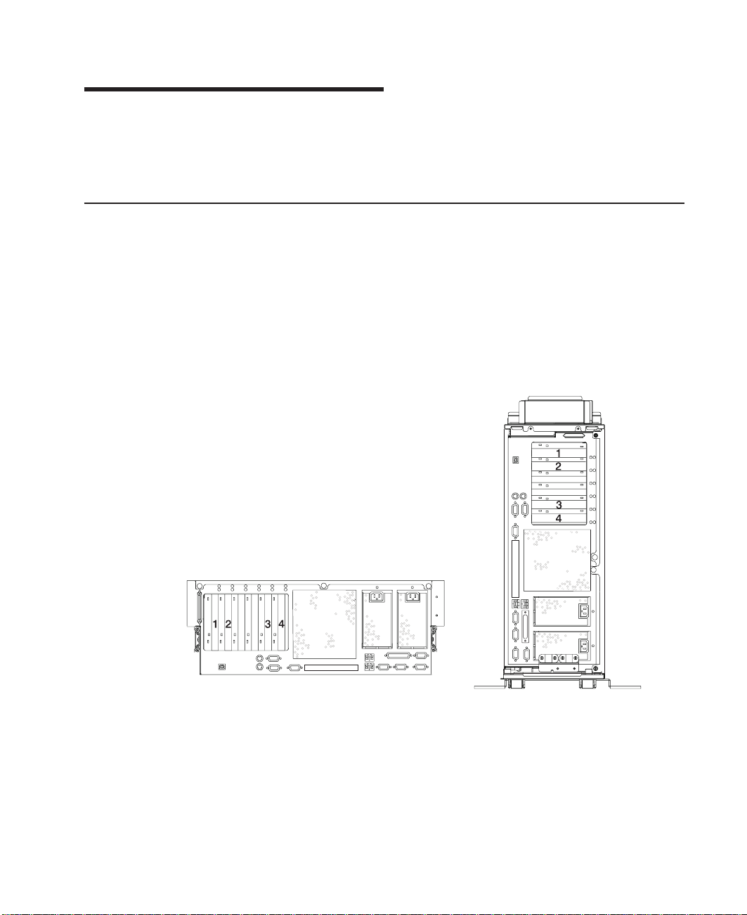
Four PCI slots are available. Slots numbered 3 and 4 are 64-bit capable at 133 MHz,
3.3 volts. Use these slots with PCI adapters that demand high performance. Slots
numbered 1 and 2 are 64-bit capable at 66 MHz, 3.3 volts. Use these slots with PCI
adapters that do not demand high performance. All slots are capable of running either
64-bit or 32-bit adapters. However, a 32-bit adapter operates in a 32-bit mode and
shows no performance advantage while running in a 64-bit slot. The following
illustration shows the PCI Adapter Slot locations when viewing from the rear of the
system.
Processors
v One and two-way cards with POWER4 1.0 GHz microprocessors.
Note: Only a single 1-way card is allowed per server at one time; therefore, a 3-way
configuration is unavailable.
v An upgrade from a 1-way (FC 5131) to a 2-way (FC 5132) is available by feature
conversion.
v 32 MB L3 cache per-processor card
1
Page 20

Memory
Media Drives
v 1 GB to 32 GB ECC DDR SDRAM memory
v Memory DIMMs plug into the processor cards (8 DIMM slots per card).
v DIMMs must be populated in quads (a single memory feature contains four DIMMs).
v Memory quads may be different memory sizes.
v A system with a single processor card (1- or 2-way) may have a maximum of 16 GB
of memory based on the maximum memory feature available.
Two media bays are part of the typical system configuration. One of the media bays will
be configured with either CD-ROM or DVD-RAM.
v Media bay 1 can accommodate an IDE CD-ROM or a SCSI DVD-RAM. (The
DVD-RAM will read CD-ROM installation media.)
v Media bay 2 can accommodate a DVD-RAM, diskette drive, or tape drive. Contact
your sales representative to check the availablility of 8 mm tape drives.
Four hot-plug disk-drive bays:
v 18.2 GB to 293.6 GB of disk storage
v The following disk drive sizes and speeds are available:
– 18.2 GB Ultra3 10K RPM 1 inch
– 36.4GB Ultra3 10K RPM 1 inch
– 73.4 GB Ultra3 10K RPM 1 inch
– 36.4 GB Ultra3 15K RPM 1 inch
Contact your sales representative for an updated listing of hot-plug disk-drive sizes.
Power supply
Up to two power supplies maximum per system; the second power supply is for
redundant power.
v AC input type 120V/240V
v Single phase
Keyboard
v Standard: 101-key enhanced keyboard
v 101/102 or 106-key enhanced keyboard is also available
Mouse
v Three-button
2 pSeries 630 Model 6C4 and Model 6E4 User’s Guide
Page 21

Operator Panel
v 32-character LED diagnostics display
v LEDs for power on, attention, SCSI activity, and LAN activity
v Buttons for power on, system reset, and service processor reset
System Reset
Service Processor Reset
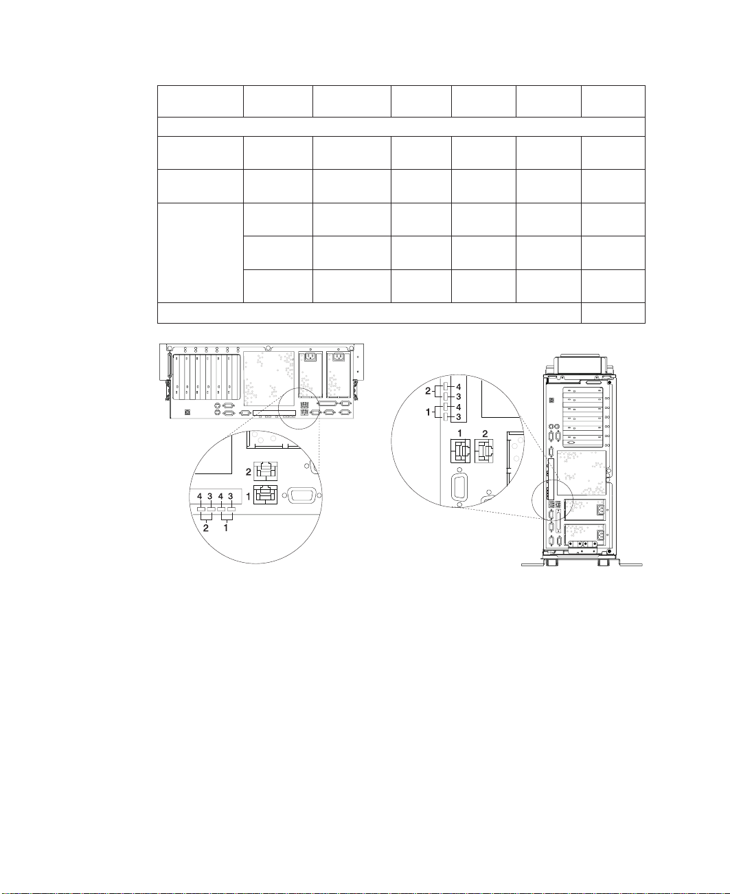
Input/Output Ports
v One 25-pin parallel
v Keyboard
v Mouse
v Two Ultra3 SCSI (one to internal 4-pack disk drive backplane, one to external VHDCI
mini 68-pin port)
v Integrated Drive Electronics (IDE)
v Two 10/100 Ethernet (IEEE 802.3 compliant)
v Three serial ports. Serial port 1 (S1) has two physical connectors, one RJ-48 located
in front on the operator panel, and a 9-pin D-shell located on the rear of the chassis.
The other two serial ports are 9-pin D-shell connectors and are located on the rear of
the system chassis.
Current usage for the serial port connectors are as follows:
Dumps AIX (if dump is enabled) and reboots.
Resets the service processor (standby mode).
Serial Port
Number
Serial Port 1 (S1
Front)
Serial Port 1 (S1
Rear)
Serial Port 2 (S2) Rear of the
Serial Port 3 (S3) Rear of the
Location Applicable Usage Examples
Operator Panel Service Agent, PDA System Management Applications
Rear of the
System
System
System
(for example: handheld devices, laptop sytems), Service
Processor menus
Service Processor menus, Service Agent, PDA System
Management Applications (interface cable required)
Service Processor menus, HACMP
HACMP, UPS, and Modems
Note: Serial port 1 is never used to run HACMP or UPS. If you are configuring your
system to run HACMP and UPS concurrently, you must connect HACMP to
serial port 2 and UPS to serial port 3.
port 2. If you decide to diconnect HACMP, you
Do Not
run UPS connected to serial
must
reset the service
processor reset pin-hole switch before running another application. The
service processor reset pin-hole switch is located on the operator panel.
Chapter 1. Introducing the System 3
Page 22
Security Features
Model 6C4 and Model 6E4 allow you to set the following types of passwords to limit
access to these systems:
v General-access password - set only from the service processor menus. It provides
limited access to the service processor menus and is usually available to all users
who are allowed to power on the system.
v Privileged-access password - Set from the service processor menus or from System
Management Services (SMS) utilities. Used by the system administrator or root user
and allows access to all service processor functions.
Front View
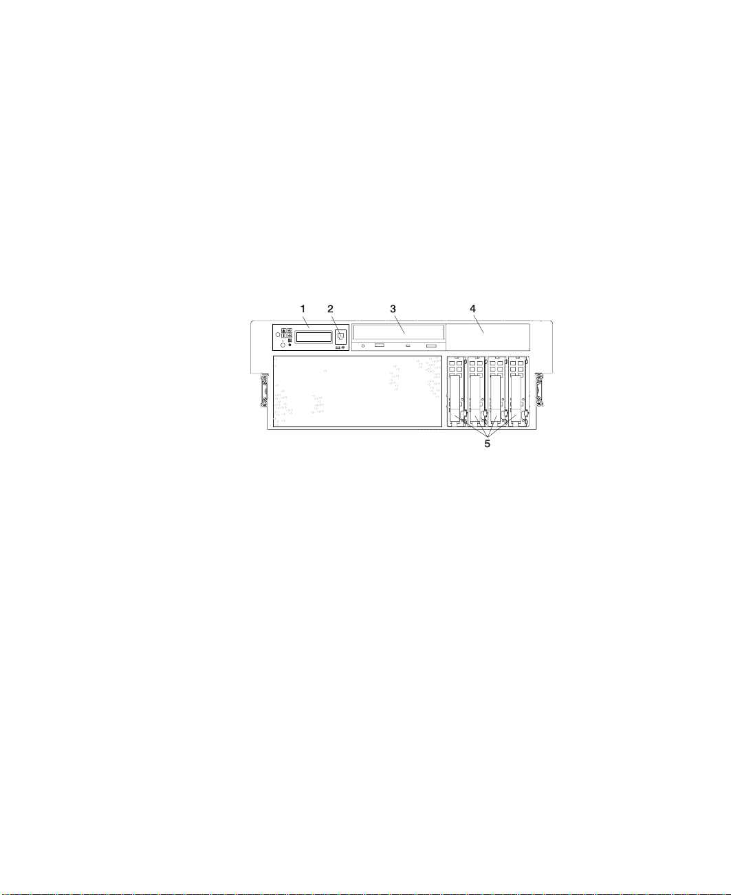
Model 6C4
1 Operator Panel
2 Front Serial Connector
3 IDE CD-ROM Drive
4 Media Bay
5 Hot-Plug Disk Drives
4 pSeries 630 Model 6C4 and Model 6E4 User’s Guide
Page 23
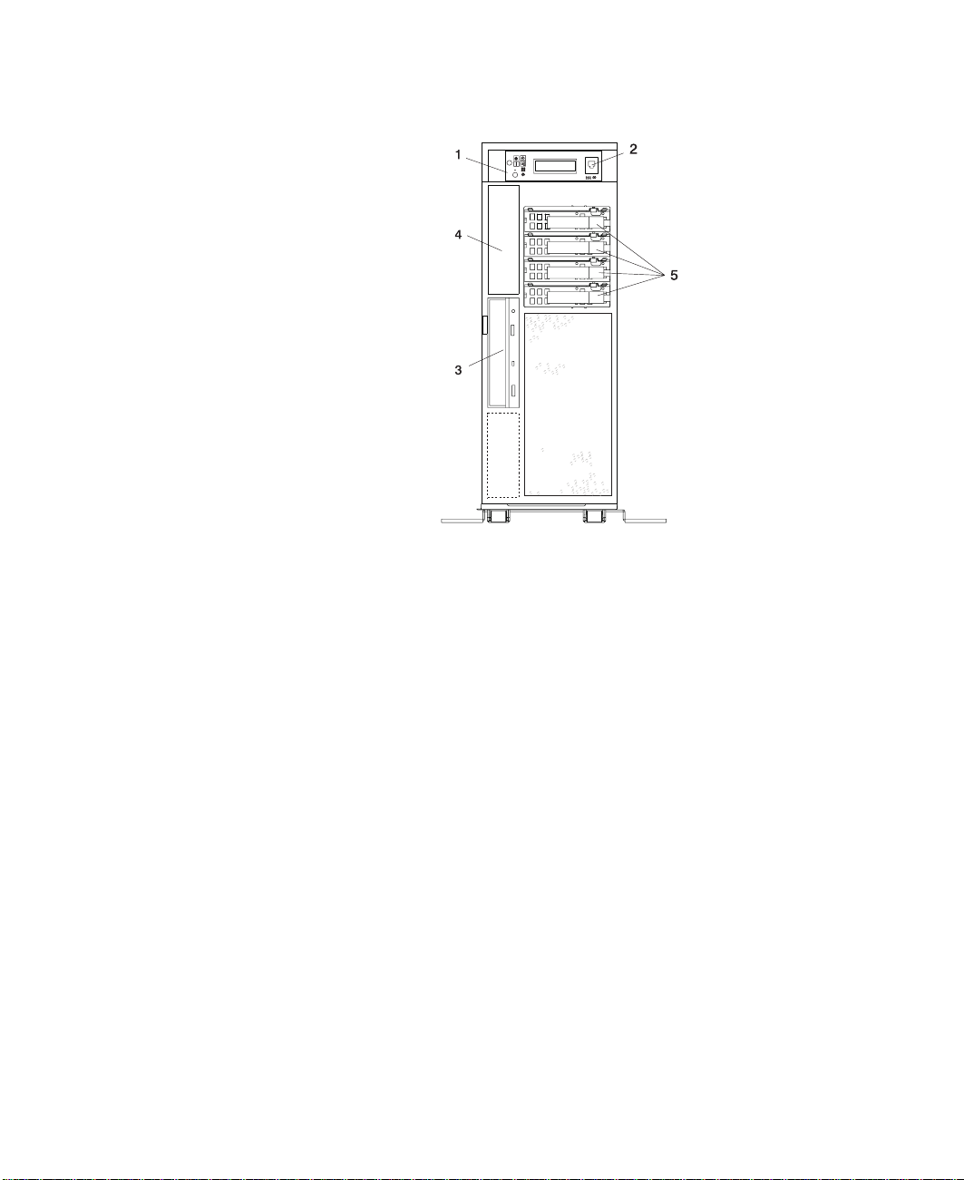
Model 6E4
1 Operator Panel
2 Front Serial Connector
3 IDE CD-ROM Drive
4 Media Bay
5 Hot-Plug Disk Drives
Chapter 1. Introducing the System
5
Page 24
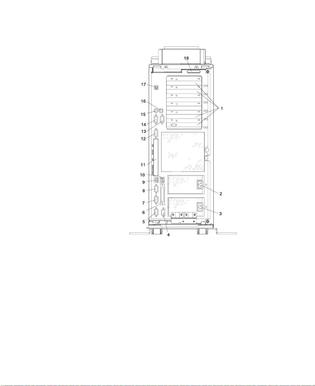
Rear View
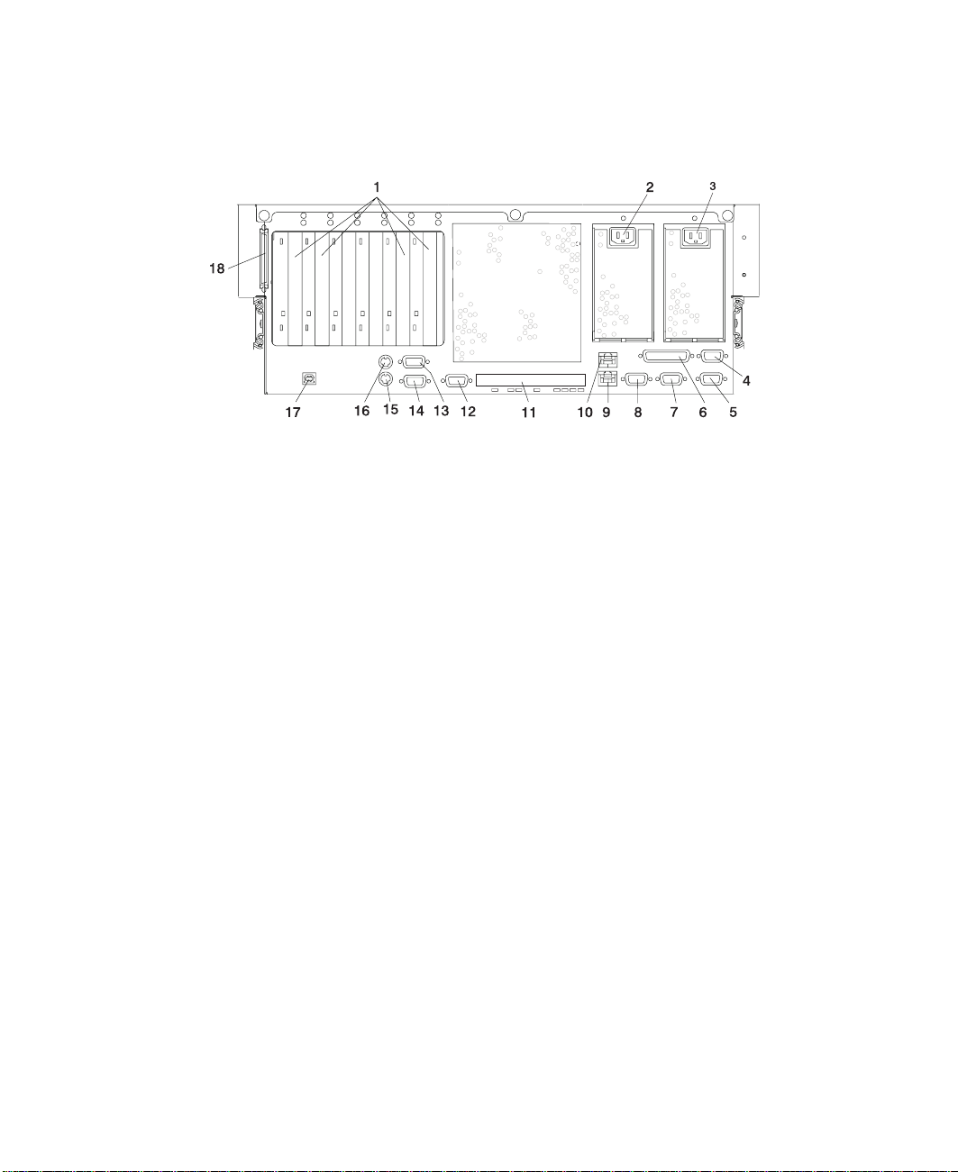
Model 6C4
1 4 PCI slots 64-Bit 10 Ethernet Connector 2
2 Redundant Power Cable Receptacle 11 Connector Cover (These connectors
3 Primary Power Cable Receptacle 12 Serial Connector 2
4 System Power
Control Network Connector
SPCN2
5 System Power
Control Network Connector
SPCN1
6 Parallel Connector 15 Mouse Connector
7 Hardware Management
Console Connector
HMC2
8 Hardware Management
Console Connector
HMC1
9 Ethernet Connector 1 18 External SCSI Connector
are not used with your system.)
13 Serial Connector 3
14 Serial Connector 1
16 Keyboard Connector
17 Rack Indicator
6 pSeries 630 Model 6C4 and Model 6E4 User’s Guide
Page 25
Model 6E4
1 4 PCI slots 64-Bit 10 Ethernet Connector 2
2 Redundant Power Cable Receptacle 11 Connector Cover (These connectors
3 Primary Power Cable Receptacle 12 Serial Connector 2
4 System Power
Control Network Connector
SPCN2
5 System Power
Control Network Connector
SPCN1
6 Parallel Connector 15 Mouse Connector
7 Hardware Management
Console Connector
HMC2
8 Hardware Management
Console Connector
HMC1
9 Ethernet Connector 1 18 External SCSI Connector
are not used with your system.)
13 Serial Connector 3
14 Serial Connector 1
16 Keyboard Connector
17 Rack Indicator
Chapter 1. Introducing the System
7
Page 26
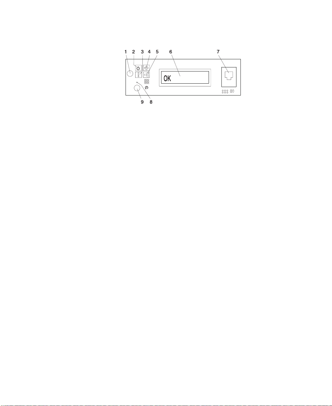
Operator Panel
1 Power-On Button 6 Operator Panel Display
2 Power-On LED 7 (FS1) Front Serial
Connector (RJ48 Connector)
3 Attention LED 8 Service Processor Reset
Switch (Pinhole)
4 SCSI Port Activity LED 9 System Reset Button
5 Ethernet Port Activity LED
8 pSeries 630 Model 6C4 and Model 6E4 User’s Guide
Page 27

Chapter 2. Using the System
This chapter provides information on how to start and use the system.
Starting the System Unit
1. Set the power switches of the attached devices to On.
Note: When the system is plugged in but not powered on, the Power-On LED
flashes slowly.
2. If the LED is not flashing and OK is not displayed, ensure that the power cord,
located at the back of the system unit, is plugged into a grounded electrical outlet.
3. If this does not solve the problem, go to Chapter 8, “Hardware Problem
Determination” on page 157.
4. Press the Power-On button.
When you press the Power-On button, the Power-On LED comes on, and the
system starts a POST (power-on self-test).
During POST, progress codes display in the operator panel display.
5. If the Power-On LED does not come on and there is no indication of power when
you press the Power-On button, go to Chapter 8, “Hardware Problem Determination”
on page 157.
Stopping the System Unit
Attention: When you use the shutdown procedure for your system, follow the correct
shutdown procedure before you stop the system. Failure to do so can result
in the loss of data. The system is powered down by the shutdown
procedure.
1. At a command line, type shutdown to stop the operating system.
2. After you shut down the operating system, set the power switches of any attached
devices to Off.
3. If you will be servicing the system, unplug the system-unit power cable from the
electrical outlet.
Reading the Operator Panel Display
The operator panel display is used to:
v Track the progress of the system unit self-tests and configuration program
v Display codes when the operating system comes to an abnormal end
v Display system messages
9
Page 28
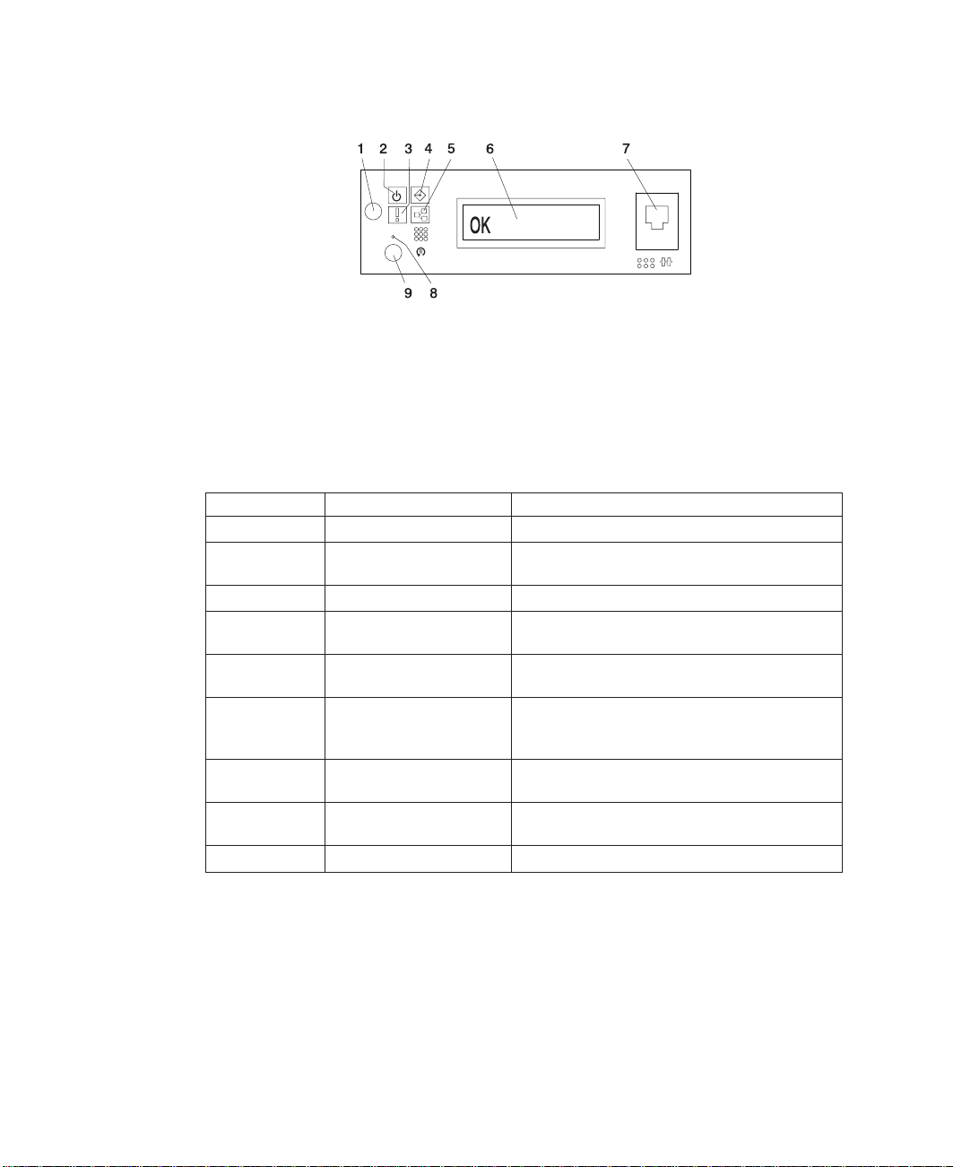
Operator Panel
1 Power-On Button 6 Operator Panel Display
2 Power LED 7 (FS1) Front Serial
3 Attention LED 8 Service Processor Reset
4 SCSI Port Activity 9 System Reset Button
5 Ethernet Port Activity
Number Component Name Component Description
1 Power-On Button Turns the system power on and off.
2 Power LED Normal State - LED is on when system is
3 Attention LED Normal State - LED is off.
4 SCSI Port Activity Normal State - LED is on when there is SCSI
5 Ethernet Port Activity Normal State - LED is on when there is Ethernet
6 Operator Panel Display Displays current status of system startup, or
7 Front Serial Connector
(FS1)
8 Service Processor Reset
Switch (Pinhole)
9 System Reset Button Resets the system
connected to a power source.
activity.
activity.
diagnostic information in the event of a hardware
problem.
Serial port uses RJ48 connector. Use to plug in
external devices at the front of the system unit.
Service Personnel Use
Connector (RJ48 Connector)
Switch (Pinhole)
10 pSeries 630 Model 6C4 and Model 6E4 User’s Guide
Page 29

Component LEDs
Individual LEDs are located on or near the failing components. The LEDs are located
either on the component itself or on the carrier of the component (for example, memory
card, fan, memory module, CPU). LEDs are either green or amber.
Green LEDs indicate one of two things:
v Electrical power is present.
v Activity is occuring on a link. (The system could be sending or receiving information.)
Amber-colored LEDs indicate a fault or identify condition. If your system or one of the
components on your system has an amber-colored LED turned on or blinking, identify
the problem and take the appropriate action to restore the system to normal.
The following table identifies the location, color and status of your system component
LEDs.
Chapter 2. Using the System 11
Page 30

Unit
(FRU)
Rack
Indicator
System
Unit
Fans Identify Fan Top Amber
Power
Supply
(AC)
Disk
Drives
(DASD)
Optional
Media
PCI
Adapter
Connectors
(Slots)
LED
Function
Drawer
Sum
AC Input Green (1x) No Input AC Good N/A
Attention
Power
Input
Source
Fault Power
DC Output
Good
Activity
Remove
Identify
Activity
Identify
Location LED
Top of
Rack
Operator
Panel +
Rear
Operator
Panel +
Rear
Power
Supply
Front +
Top
Supply
Front +
Top
Power
Supply
Front +
Top
DASD
Board
DASD
Board
Chassis
Rear,
Inside
System
Next to
Adapter
Chassis
Rear,
Inside
System
Next to
Adapter
Color
Power and Packaging LEDs
Amber
(1x)
Amber
(2x)
Green (2x)
(4x)
Green (1x) No Input AC Input
Amber
(1x)
Green (1x)
Green (4x) No Activity Activity N/A
Amber
(4x)
Electronics Component LEDs
Green Refer to the Following PCI Adapter Table
Amber Refer to the Following PCI Adapter Table
OFF ON Blink
Normal Fault Identify
Normal Fault Identify
No AC System
On
Normal Fault N/A
Good
Normal N/A Identify- Power
DC Off DC Good Standby
Normal Action Identify
No LED
v Standby - slow
v transition of power
on/off - fast
N/A
Control Comm. Failed
.25 Hz
12 pSeries 630 Model 6C4 and Model 6E4 User’s Guide
Page 31

Unit
(FRU)
Memory
DIMMs
CEC
Backplane
Processor
Board
PCI Riser
Card
Disk Drive
Backplane
PCI Adapter Table
LED Inactivity Active Identify Action
Green + Amber (2
LEDs)
LED
Function
Identify Processor
Identify CEC
Identify Processor
Identify PCI Riser
Location LED
Housing
(Top)
Backplane
Housing
(Top)
Card
Green - Off
Amber - Off
Color
Power and Packaging LEDs
Amber
(8x)
Amber
(1x)
Amber
(1x)
Amber
(1x)
Green - On
Amber - Off
OFF ON Blink
Normal Identify
Normal Identify
Normal Identify
Normal Identify
No LED
Green - On
Amber - Blinking
Green - Off
Amber - Blinking
Chapter 2. Using the System
13
Page 32
Component LED
RIO Port Identify CEC
SCSI Port Activity Operator
Ethernet Port
Ethernet 1,
Ethernet 2
For more about the Ethernet connections see the following illustration.
Function
Mode
Activity
Activity
Location LED
Port LED Indicators
Backplane
Panel
Chassis Rear Green
Chassis Rear Green
Operator
Panel
Color
Amber
(2x)
Green
(1x)
(2x)
(2x)
Green
(1x)
OFF ON Blink
Normal N/A Identify
No Activity Activity
10 Mbit
Mode
No Activity Activity
No Activity Activity
100 Mbit
Mode
1 Ethernet 1 Connector and LED
2 Ethernet 2 Connector and LED
3 Mode
4 Activity
14 pSeries 630 Model 6C4 and Model 6E4 User’s Guide
Page 33

Resetting the LEDs
After the repair action is completed, do the following:
1. Log in as root user.
2. At the command line, type diag.
3. Select Task Selection.
4. Select Log Repair Action.
5. Select the device that was repaired.
6. Press F10 to exit diagnostics.
If the Attention LED remains on after you have completed the repair action and reset
the LEDs, call for service support.
Reporting the Problem
After you have determined which component is failing, report the problem.
1. Record the following information before calling for service:
v Machine type and model number
v Server serial number
v Any error codes that appear in the operator panel display or console
v The adapter or device containing the lit amber-colored LED
2. Call for service. You will be given the choice to replace the failing component
yourself or have a service representative replace it for you. If you decide to replace
the failing component, go to “Repair Action” for instructions.
Repair Action
After you have determined which component is failing, a repair action is necessary.
1. Run the system verification procedure. Refer to Installing Options in the
Model 6C4 and Model 6E4 Installation Guide
installation, removal and replacement.
2. Record the following information before calling for service:
v Machine type and model
v Server serial number
v Any error codes that appear in the operator panel display or on the console
v Any LEDs that are lit on the indicator panel
3. Call for service.
4. After the repair action is completed, go to “Resetting the LEDs”, and reset the
LEDs.
for instructions on component
Chapter 2. Using the System 15
pSeries 630
Page 34

Using the Keyboards
There are several keyboards available for the system. The keyboards have various
keys that enter data and control the cursor location. The keyboards can be engraved for
the languages of various countries.
The functions of each keyboard depend on the software used. The character sets for
the keyboards are contained and explained in the documentation for your operating
system.
Esc F1 F2 F3 F4 F6 F7 F8F5 F9 F10 F11 F12 Pause
!
123
QWER YUIT OP
Tab
Caps
Lock
Shift
Ctrl Alt
Function Keys
@
#
$% &
4567
ASDFGHJKL :
ZXCVBNM
*
8
()
90
<
>
,
_
-
;
Alt Ctrl
Num
Caps
Print
Scroll
Screen
SysRq
+
Backspace
=
"
,
?
Shift
/.
Insert
Delete
Enter
Lock
Lock
Break
Page
Home
Up
Page
End
Down
Lock
Num
/*-
Lock
789
Home PgUp
654
321
End
PgDn
.
0
Ins Del
Scroll
Lock
+
Enter
Typewriter Keys
Control
Keys
Numeric
Keypad
The keyboard is divided into four sections:
v
Function keys
are multipurpose keys and their function is controlled by the operating
system.
v
Typewriter keys
are similar to a standard typewriter. Their function is controlled by
the software.
v
Control keys
move the cursor on the screen and do programmed control functions.
The movement and functions depend upon the application used.
v
Numeric keypad
is arranged like a calculator to help when typing numbers.
On all of the keyboards, you can adjust the tilt position for typing comfort. To tilt the
keyboard, pull out on the keyboard legs. The legs snap into position. To decrease the
tilt of the keyboard, rotate the keyboard legs until they snap into the bottom of the
keyboard case.
The keyboard cable plugs into the keyboard connector at the rear of the system.
16 pSeries 630 Model 6C4 and Model 6E4 User’s Guide
Page 35

Using the Three-Button Mouse
The mouse is a hand-operated locating device. A three-button mouse is available for
use with the system. Consult your application publication for the exact use of the
three-button mouse.
You can use the mouse to perform such functions as positioning a cursor, selecting
items from a menu, or moving around in your document much easier and faster than if
you used only the keyboard. The cursor moves exactly as you move the mouse on a
flat surface, such as a desktop.
With the mouse buttons, you can perform functions such as selecting and deselecting
options, extending your selection, or choosing a command. The precise function of your
mouse depends on the software you are using.
The mouse cable plugs into the mouse connector at the rear of the system.
Handling the Mouse Correctly
For best operation, handle the mouse with care. Incorrect handling can damage the
mouse.
Do not:
v Operate the mouse on cloth, unfinished wood, newspaper, or carpet.
v Drop or hit the mouse.
v Carry the mouse by holding onto the cable.
v Expose the mouse to extreme temperatures or direct sunlight.
v Place the mouse in liquid spills.
Caring for the Mouse
The operating surface for the mouse should be smooth, clean, and flat. For example,
you can operate the mouse on the following surfaces:
v Finished wood
v Glass
v Enamel
v Plastic
v Paper (except newspaper)
v Metal
Chapter 2. Using the System 17
Page 36

Rough surfaces collect contaminants that can be transferred to the interior of the mouse
by the ball. Rough surfaces can also cause the pads located on the bottom of the
mouse to prematurely wear. A deeply pitted surface could cause erratic operation of the
mouse. The surface you use should be free from spills, dirt, dust, lint, wax, eraser dust,
and other foreign matter.
To care for the mouse:
v Inspect the work surface for spills or other contaminants.
v Dust the work surface.
v If you are using a paper pad, inspect it for wear and replace it if necessary.
Cleaning the Mouse
Use the following steps to clean the mouse:
1. Remove the retaining ring by turning it counterclockwise, in the direction of the
arrow, as shown in the illustration.
Retaining Ring
Ball
Cavity
2. Remove the ball.
3. Inspect the ball for contaminants. Wipe it clean with a dry, lint-free cloth.
4. If the ball is dirty, wash it in warm, soapy water. Rinse and wipe the ball with a
lint-free cloth until dry.
5. Inspect the ball cavity in the mouse for foreign materials. If there are any foreign
materials, remove them.
6. Replace the ball.
7. Replace the retaining ring on the mouse and align it with the open slots in the ball
cavity.
8. Turn the retaining ring clockwise until the open slots are covered and you hear the
ring snap into place.
18 pSeries 630 Model 6C4 and Model 6E4 User’s Guide
Page 37

Using the 3.5-Inch Diskette Drive
A 1.44 MB diskette drive is an optional feature for this system. Contact your sales
representative before purchasing a diskette drive for this system.
The 1.44 MB diskette drive can format, read, and write diskettes compatible with the
following diskette drives:
v 1.0 MB diskettes with 720 KB formatted data capacity
v 2.0 MB diskettes with 1.44 MB formatted data capacity (High Density)
Format the diskette according to its specified capacity.
Write-Protecting 3.5-Inch Diskettes
Write-protecting diskettes is necessary so that important information is not accidentally
lost. When diskettes are write-protected, you can read information from the diskettes,
but you cannot write information to them.
There is a write-protect tab on the 3.5-inch diskette. To locate the write-protect tab, turn
the diskette over with the label facing down.
To prevent writing onto a diskette, slide the write-protect tab to open the protect slot, as
shown in the illustration.
To allow writing onto a diskette, slide the write-protect tab to cover the protect slot, as
shown in the illustration.
Chapter 2. Using the System 19
Page 38

Loading and Unloading the 3.5-Inch Diskette
To load a diskette into the drive, insert the diskette in the diskette drive with the labeled
metal shutter first. Push the diskette into the drive until you hear a click. The click
indicates that the diskette is securely in position in the drive.
To unload the diskette, push the diskette-unload button. The diskette unloads partially
from the drive. Remove the diskette.
Using the CD-ROM Drive
CAUTION:
A class 1 laser is contained in the device. Do not attempt to operate the drive
while it is disassembled. Do not attempt to open the covers of the drive as it is
not serviceable and is replaced as a unit.
C07
This section describes the features of the 40X SCSI-2 CD-ROM drive and provides
instructions for handling the drive and CD-ROM discs. The CD-ROM is a half-high,
5.25-inch, 8-bit, single-ended, tray-loading drive. Its features include the following:
v SCSI-2 interface supports both synchronous and asynchronous data transfer
v High-speed data transfer rate of 2100 KB per second (14X) at inner diameter and
4800 KB per second (32X) at outer diameter due to constant RPM spin rate
v High-speed synchronous burst rate of 10 MB per second
v Average random access time of 90 ms
v Loading tray accommodates both 8-cm discs (in the horizontal orientation only) and
12-cm discs
v Reads multi-session discs
v Reads CD-recordable discs
v Reads CD-RW discs
v Supports all major CD-ROM formats: Mode 1, Mode 2, XA, CDDA, and audio
v Headphone output and line output for audio
20 pSeries 630 Model 6C4 and Model 6E4 User’s Guide
Page 39

Front View of CD-ROM Drive
1 2
6
Understanding the Status Lights
The status lights indicate the operational status of the drive. The various conditions are
as follows:
If light is: Condition is:
Off Drive is in standby mode with or without a disc loaded.
Blinking (green) Any of the following:
On (amber) Hardware error condition found during initialization.
5
1 Compact Disc Tray
2 Emergency Eject Hole
3 Load/Unload Button
4 Status Light
5 Volume Control
6 Headphone Jack
v Drive tray is inserted. The light blinks while the drive
v Drive is reading data. The light blinks while data is being
v Drive is in Play Audio Mode. The light blinks while the audio
Note: If this occurs, contact your service representative.
4 3
completes the initialization checkout.
read.
is playing.
Chapter 2. Using the System 21
Page 40

Handling Compact Discs
Compact discs are high-density media that must be handled with care and kept clean to
ensure that they remain readable. Use the following precautions to ensure reliability:
v Hold the compact disc by the edges. Do not touch the surface of the compact disc.
v To remove dust or fingerprints, wipe the compact disc from the center to the outside
of the compact disc as shown, using a lint-free cloth.
Attention: Wiping the compact disc in a circular direction can cause loss of data.
v Do not write on the surface.
v Do not store or place the compact disc in direct sunlight.
v Do not use benzene, thinners, or other cleaners to clean the compact disc.
v Do not bend the compact disc.
Other Handling Considerations
Be sure to take the following additional precautions when you use the CD-ROM drive:
v Remove compact discs from the tray before you move the drive anywhere.
v Do not place the drive where any of the following conditions exist:
– High temperature
– High humidity
– Excessive dust
– Excessive vibration or sudden shock
– Inclined surface
– Direct sunlight
v Do not insert foreign objects into the drive.
v Do not remove the drive covers or attempt to service the drive yourself.
22 pSeries 630 Model 6C4 and Model 6E4 User’s Guide
Page 41
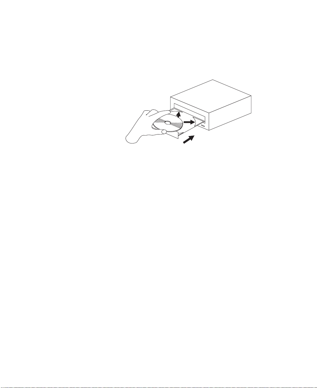
Loading a Compact Disc
To load a compact disc into the drive, do the following:
1. Press the Load/Unload button to open the tray. The tray slides out of the drive.
2. Place the compact disc in the tray with the label facing up.
3. Press the Load/Unload button, or gently push in the tray, to close the tray.
Note: Be sure that none of the vertical retaining tabs are extended when you use
the drive in the horizontal position.
Opening the Tray Manually
The compact disc tray automatically opens when you press the Load/Unload button. If it
does not automatically open, follow these steps to force it open manually:
1. Shut down and turn off the power to your system.
2. Insert the straightened end of a paper clip into the emergency eject hole until you
feel some resistance. If you are not sure where the emergency eject hole is located,
see “Front View of CD-ROM Drive” on page 21.
3. Continue to push in the paper clip while you pull out the tray with your fingernail.
4. Pull the tray completely open and remove the disc. It is normal for the tray to make
a clicking sound while you are pulling it open.
Playing an Audio CD
To play an audio CD, you must have headphones connected to the headphone jack
located on the front of the drive, or connected to the line-out connector located on the
back of the system. You must also have an audio software application installed.
The headphone jack provides the connection for headphones using a 3.5-mm (1/8")
stereo mini-plug. The volume control adjusts the audio output level for the headphones.
Chapter 2. Using the System 23
Page 42

Using the Service Processor and Service Director Features
The service processor and service director features protect users against unnecessary
system downtime by keeping support personnel (both internal and external) aware of
any unexpected changes in the system environment. In combination, the two features
provide a flexible solution to automated system maintenance.
Service Processor
The service processor runs on its own power boundary and continually monitors
hardware attributes, the AIX operating system, and the environmental conditions within
the system. Any system failure which prevents the system from returning to an
operational state (a fully functional AIX operating system) is reported by the service
processor. The service processor is controlled by firmware and does not require the AIX
operating system to be operational to perform its tasks. If any system failures are
detected, the service processor has the ability to take predetermined corrective actions.
The methods of corrective actions are:
v Surveillance
v Call Home
v AIX operating system monitoring
Surveillance is a function in which the service processor monitors the system through
heartbeat communication with the system firmware. The
that the firmware can monitor. During system startup, the firmware surveillance monitor
is automatically enabled to check for heartbeats from the firmware. If a heartbeat is not
detected within a default period, the service processor cycles the system power and
attempts to restart until the system either restarts successfully, or a predetermined retry
threshold is reached. In the event the service processor is unsuccessful in bringing the
system online (or in the event that the user asked to be alerted to any service
processor-assisted restarts), the system can call home to report the error.
heartbeat
is a periodic signal
The call home function can be initialized to call either a service center telephone
number, a customer administration center, or a digital pager telephone number. The
service processor can be configured to stop at the first successful call to any of the
numbers listed, or can be configured to call every number provided. If connected to the
service center, the service processor transmits the relevant system information (the
system’s serial number and model type) and service request number (SRN). If
connected to a digital pager service, the service processor inputs a customer voice
telephone number defined by the customer. An established sequence of digits or the
telephone number to a phone near the failed system could be used to signal a system
administrator to a potential system failure.
During normal operations, the service processor can also be configured to monitor the
AIX operating system. If AIX does not respond to the service processor heartbeat, the
service processor assumes the operating system is hung. The service processor can
automatically initiate a restart and, if enabled, initiate the call home function to alert the
appropriate parties to the system hang. Enabling operating system surveillance also
affords AIX the means to detect any service processor failures and report those failures
to the service director application.
24 pSeries 630 Model 6C4 and Model 6E4 User’s Guide
Page 43

Unlike the service director, the service processor cannot be configured in a client/server
environment where one system can be used to manage all dial-out functionally for a set
of systems.
Prior to installing the service director feature, ensure that you have the latest levels of
service processor microcode and system firmware. You also need a properly configured
modem. For more information on configuring a modem, see “Call-In/Call-Out Setup
Menu” on page 52.
Service Director
The Service Director is a software extension to the AIX operating system that monitors
the system while the AIX operating system is running. The Service Director monitors
and analyzes all recoverable system failures, and, if needed, can automatically place a
service call to a service center (without user intervention).
The service center receives the machine type/serial number, host name, SRN, and a
problem description. The service center analyzes the problem report and, if warranted,
dispatches a service person to the customer site. The service center also determines if
any hardware components need to be ordered prior to the service person’s arrival.
The Service Director code also gives the user the option to establish a single system as
the problem reporting server. A single system, accessible over the user network, can be
used as the central server for all the other systems on the local area network (LAN) that
are running the Service Director application. If the Service Director application on a
remote client decides a service request needs to be placed, the client forwards the
information to the Service Director server, which dials the service center telephone
number from its locally attached modem. In this scenario, the user only needs to
maintain a single analog line for providing call-out capabilities for a large set of servers.
When used in a scalable parallel (SP) environment, a client/server type implementation
is configured. The Service Director client code runs on each of the SP nodes. The
server component runs on the control workstation. In the event of any system failures,
the relevant information is transmitted to the control workstation through the integrated
Ethernet. After it has been alerted to the system failure, the control workstation initiates
actions to prepare and send the service request.
A modem is required for enabling automated problem reporting to the service center.
Configuration files for several types of modems are included as part of the Service
Director package. Refer to “Call-In/Call-Out Setup Menu” on page 52 for more
information on configuring your modem.
Chapter 2. Using the System 25
Page 44

26 pSeries 630 Model 6C4 and Model 6E4 User’s Guide
Page 45

Chapter 3. Using the Service Processor
Notes:
1. Any section of this chapter that reference partioned systems or partitioning a system
do not pertain to Model 6C4 or Model 6E4.
2. The information in this chapter regarding the configuring of serial ports, and
modems attached to those serial ports, applies only to the serial ports (S1 and S2)
on the CEC backplane (location U0.1-P1). None of this information is applicable to
the serial ports, or modems attached to those serial ports, on the HMC.
The service processor runs on its own power boundary and continually monitors
hardware attributes and the environmental conditions within the system. The service
processor is controlled by firmware and does not require the AIX operating system to be
operational to perform its tasks.
The service processor menus allow you to configure service processor options, as well
as enable and disable functions.
Service processor menus are available using an ASCII terminal or an HMC virtual
terminal window when OK is displayed on the operator panel or when the service
processor has detected a system problem (such as a surveillance failure).
Service Processor Menus
The service processor menus are divided into the following groups:
v General user menu - the user must know the general-access password.
v Privileged user menus - the user must know the privileged-access password.
If the system is powered off, the service processor menus can be accessed locally or
remotely on the following:
v Serial port 1 (S1)
v Serial port 2 (S2)
v HMC
27
Page 46

Accessing the Service Processor Menus Locally
Service processor menus can be accessed by opening a virtual terminal window on the
HMC, or by attaching an ASCII terminal to serial port 1 (S1) or serial port 2 (S2). After
OK displays in the operator panel, press any key on the keyboard to signal the service
processor.
Note: The service processor menus cannot be accessed simultaneously on a virtual
terminal window on the HMC and on an ASCII terminal. Accessing the menus on
the HMC locks out access to the ASCII terminals and vice versa.
When you gain access, the service processor prompts you for a password (if one is
set), and when verified, displays the service processor menus.
The service processor menu prompt, represented by 0> or 1>, indicates the serial port
to which the terminal is connected.
v An ASCII terminal can have the following prompts:
– 0> indicates serial port 1 (S1)
– 1> indicates serial port 2 (S2)
v The HMC always indicates a prompt of 0>
Accessing the Service Processor Menus Remotely
If your system has a modem connected to serial port 1 or serial port 2 and is configured
for call-in (see “Modem Configuration Menu” on page 53), the service processor menus
can be accessed remotely as follows:
1. With the system powered off, call in from a remote terminal.
2. The service processor detects ring-indicate and prompts you for a password (if one
is set). When verified, the service processor menus display remotely.
Saving and Restoring Service Processor Settings
All the settings that you make (except language) from the service processor menus can
be backed up either for recovering from a fault that may corrupt these settings, or for
replicating these settings to other servers that include a service processor.
The service aid, Save or Restore Hardware Management Policies, can be used to save
your settings after initial setup or whenever the settings must be changed for system
operation purposes.
It is strongly recommended that you use this service aid for backing up service
processor settings to protect the usefulness of the service processor and the availability
of the system. Refer to “Save or Restore Hardware Management Policies,” in
“Introduction to Tasks and Service Aids” for information about this service aid.
Menu Inactivity
The service processor exits menu mode after ten minutes of inactivity and displays a
message indicating that it has done so. Pressing any key on the virtual terminal window
causes the main menu to display.
28 pSeries 630 Model 6C4 and Model 6E4 User’s Guide
Page 47

General User Menu
The menu options presented to the general user are a subset of the options available to
the privileged user. The user must know the general-access password, if one is set, to
access this menu.
1. Power-on System
2. Power-off System
3. Read VPD Image from Last System Boot
4. Read Progress Indicators from Last System Boot
5. Read Service Processor Error Logs
6. Read System POST Errors
99. Exit from Menus
0>
v Power-on System
Allows the user to start the system using the current virtual terminal window as the
active console.
v Power-off System
This option is not available on this system.
v Read VPD Image from Last System Boot
Displays manufacturer vital product data, such as serial numbers, part numbers, and
so on, that were stored from the system boot prior to the one in progress now, for the
entire system.
GENERAL USER MENU
Chapter 3. Using the Service Processor 29
Page 48

v Read Progress Indicators from Last System Boot
Displays a number of the boot progress indicators, which may include service
processor checkpoints, IPL checkpoints, or AIX configuration codes, from the
previous system boot. This information can be useful in diagnosing system faults.
Note: If you are running one or more logical partitions, enter the partition ID (0-15)
to display progress indicators for that partition since the last system boot. If
your system is running in Full System Partition mode, this option automatically
displays details from partition 0.
The progress indicator codes are listed from top (latest) to bottom (oldest).
This information is not stored in nonvolatile storage. If the system is powered off
using the power-on button on the operator panel, this information is retained. If the
ac power is disconnected from the system, this information will be lost. For an
example, refer to “LCD Progress Indicator Log” on page 70.
v Read Service Processor Error Logs
Displays the service processor error logs. For an example, refer to “Service
Processor Error Logs” on page 69.
v Read System POST Errors
Displays additional error log information (this option is only for service personnel).
v Exit from Menus
Selecting this option will exit the service processor menus. You can re-enter the
menus by pressing any key on the console.
30 pSeries 630 Model 6C4 and Model 6E4 User’s Guide
Page 49

Privileged User Menus
The following menus are available to privileged users only. The user must know the
privileged-access password, if one is set, to access these menus.
Main Menu
A listing at the top of the main menu contains the following:
v Your system’s current firmware version
v The firmware copyright notice
v The system name given to your system during setup
You need the firmware version for reference when you either update or repair the
functions of your service processor.
The system name, an optional field, is the name that your system reports in problem
messages. This name helps your support team (for example, your system administrator,
network administrator, or service representative) to more quickly identify the location,
configuration, and history of your system. Set the system name, from the main menu,
using option 6.
Chapter 3. Using the Service Processor 31
Page 50

Note: The information under the Service Processor Firmware heading in the following
Main Menu illustration is example information only.
Service Processor Firmware
VERSION: RH011007
Copyright 2001 IBM Corporation
SYSTEM NAME
MAIN MENU
1. Service Processor Setup Menu
2. System Power Control Menu
3. System Information Menu
4. Language Selection Menu
5. Call-In/Call-Out Setup Menu
6. Set System Name
99. Exit from Menus
0>
v Service Processor Setup Menu
See “Service Processor Setup Menu” on page 33 for more information.
v System Power Control Menu
See “System Power Control Menu” on page 40 for more information.
v System Information Menu
See “System Information Menu” on page 45 for more information.
v Language Selection Menu
See “Language Selection Menu” on page 51 for more information.
v Call-In/Call-Out Setup Menu
See “Call-In/Call-Out Setup Menu” on page 52 for more information.
v Set System Name
Allows setting of the system name.
32 pSeries 630 Model 6C4 and Model 6E4 User’s Guide
Page 51

Service Processor Setup Menu
The following Service Processor Setup Menu is accessed from the Main Menu:
SERVICE PROCESSOR SETUP MENU
1. Change Privileged Access Password
2. Change General Access Password
3. Enable/Disable Console Mirroring:
Currently Enabled
4. Start Talk Mode
5. OS Surveillance Setup Menu
6. Reset Service Processor
7. Reprogram Flash EPROM Menu
8. Serial Port Snoop Setup Menu
9. Scan Log Dump Setup Menu:
Currently As Needed
98. Return to Previous Menu
99. Exit from Menus
0>
Note: Unless otherwise stated in menu responses, settings become effective when a
menu is exited using option 98 or 99.
Chapter 3. Using the Service Processor 33
Page 52

Passwords
Passwords can be any combination of up to eight alphanumeric characters. You can
enter longer passwords, but the entries are truncated to include only the first eight
characters. The privileged-access password can be set from service processor menus
or from System Management Services (SMS) utilities (see Chapter 4, “Using System
Management Services” on page 75). The general-access password can be set only
from service processor menus.
For security purposes, the service processor counts the number of attempts to enter
passwords. The results of not recognizing a password within this error threshold are
different, depending on whether the attempts are being made locally (at the system) or
remotely (through a modem). The error threshold is three attempts.
If the error threshold is reached by someone entering passwords at the system, the
service processor commands the system to resume the initial program load (IPL). This
action is taken based on the assumption that the system is in an adequately secure
location with only authorized users having access. Such users must still successfully
enter a login password to access AIX.
If the error threshold is reached by someone entering passwords remotely, the service
processor commands the system to power off to prevent potential security attacks on
the system by unauthorized remote users. The following table lists what you can access
with the privileged-access password and the general-access password.
Privileged
Access
Password
None None Service processor MAIN MENU displays.
Set None Users with the password see the service processor
Set Set Users see menus associated with the entered
General
Access
Password
Resulting Menu
MAIN MENU. Users without password cannot log in.
password.
34 pSeries 630 Model 6C4 and Model 6E4 User’s Guide
Page 53

v Change Privileged-Access Password
Set or change the privileged-access password. It provides the user with the capability
to access all service processor functions. This password is usually used by the
system administrator or root user.
v Change General-Access Password
Set or change the general-access password. It provides limited access to service
processor menus, and is usually available to all users who are allowed to power on
the system, especially remotely.
Note: The general-access password can only be set or changed after the
privileged-access password is set.
v Enable/Disable Console Mirroring
Console mirroring is supported on serial port 1 (S1) and serial port 2 (S2). When
console mirroring is enabled, the service processor sends information to all serial
ports. The serial port from which console mirroring is enabled is referred to as the
active port
. The
mirror port
is determined when keyboard input is detected from one
of the other ports. From this point on, the service processor sends information only to
the active port and the mirror port. This capability can be enabled by local or remote
users, providing local users with the capability to monitor remote sessions. Console
mirroring can be enabled for the current session only. For more information, see
“Console Mirroring” on page 68.
v Start Talk Mode
In a console-mirroring session, it is useful for those who are monitoring the session
to be able to communicate with each other. Selecting Start Talk Mode activates the
keyboards and displays for such communications while console mirroring is
established. This is a full duplex link, so message interference is possible. Alternating
messages between users works best.
Chapter 3. Using the Service Processor 35
Page 54

v OS Surveillance Setup Menu
This menu can be used to set up operating system (OS) surveillance.
OS Surveillance Setup Menu
1. Surveillance:
Currently Enabled
2. Surveillance Time Interval:
2 minutes
3. Surveillance Delay:
2 minutes
98. Return to Previous Menu
0>
– Surveillance
Can be set to Enabled or Disabled.
– Surveillance Time Interval
Can be set to any number from 2 through 255.
– Surveillance Delay
Can be set to any number from 0 through 255.
Refer to “Service Processor System Monitoring - Surveillance” on page 65 for more
information about surveillance.
v Reset Service Processor
If this option is selected, entering Y causes the service processor to reboot.
v Reprogram Flash EPROM Menu
This option requires a diskette drive to be installed in the system. If this option is
selected, and no diskette drive is present in the system, the service processor will
indicate ″Not Supported″ on the screen.
This option updates the system EPROMs. After entering Y to indicate that you want
to continue, you are prompted to enter the update diskettes. Follow the instructions
on the screen. When the update is complete, the service processor reboots.
All system EPROMs that can be reprogrammed are updated at the same time and
are as follows:
– System power control network programming
– Service processor programming
– System firmware programming
– Run-Time Abstraction Services
36 pSeries 630 Model 6C4 and Model 6E4 User’s Guide
Page 55

v Serial Port Snoop Setup Menu
This menu can be used to set up serial port snooping, in which the user can
configure serial port 1 as a ″catch-all″ reset device.
From the service processor main menu, select option 1, service processor setup
menu, then select option 8 (Serial Port Snoop Setup Menu).
SERIAL PORT SNOOP SETUP MENU
1. System reset string:
Currently Unassigned
2. Snoop Serial Port:
Currently Unassigned
98. Return to Previous Menu
1>
Use the Snoop Serial Port option to select the serial port to snoop.
Note: Only serial port 1 is supported.
Use the system reset string option to enter the system reset string, which resets the
machine when it is detected on the main console on Serial Port 1.
After serial port snooping is correctly configured, at any point after the system is
booted to AIX, whenever the reset string is typed on the main console, the system
uses the service processor reboot policy to restart.
Because pressing Enter after the reset string is not required, make sure that the
string is not common or trivial. A mixed-case string is recommended.
v Scan Log Dump Policy
A scan dump is the collection of chip data that the service processor gathers after a
system malfunction, such as a checkstop or hang. The scan dump data may contain
chip scan rings, chip trace arrays, and SCOM contents.
The scan dump data are stored in the system control store. The size of the scan
dump area is approximately 4 MB.
During the scan log dump, A8xx (in the range A810 to A8FF) displays in the operator
panel. The xx characters will change as the scan log dump progresses. If the xx
characters do not change after five minutes, the service processor is hung and must
be reset.
When the scan log dump is complete, depending on how the reboot policy is set, the
system will either:
– Go to the standby state (and the service processor menus will be available),
indicated by OK or STBY in the operator panel
OR
– Attempt to reboot.
Chapter 3. Using the Service Processor 37
Page 56

Scan Log Dump Setup Menu
1. Scan Log Dump Policy:
Currently As Needed
2. Scan Log Dump Content:
Currently As Requested
3. Immediate Dump
98. Return to Previous Menu
0> 1
Select from the following options:
(As Needed=2, Always=3)
Enter New Option:
0>
The scan log dump policy can be set to the following:
2 = As Needed
The processor run-time diagnostics record the dump data based on the
error type. This is the default value.
3 = Always
Selecting this option allows the service processor to record a scan log dump
for all error types.
The scan log dump policy can also be set from the Tasks menu in the AIX service
aids.
Option 2 displays the following screen:
Scan Log Dump Setup Menu
1. Scan Log Dump Policy:
Currently As Needed
2. Scan Log Dump Content:
Currently As Requested
3. Immediate Dump
98. Return to Previous Menu
0> 2
Select from the following options:
(As Requested=1, Optimum=2, Complete=3, Minimum=4)
Enter New Option:
0>
38 pSeries 630 Model 6C4 and Model 6E4 User’s Guide
Page 57

The scan log dump content can be set to the following:
1 = As Requested
The processor run-time diagnostics will select the contents of the dump file
based on the type of error that occurs. This is the default.
2 = Optimum
The dump will include the smallest amount of information to diagnose a
hardware error.
3 = Complete
The dump will include as much information as possible to allow the complete
analysis of hardware and software errors.
4 = Minimum
The dump will include the smallest amount of information possible (a minimum
number of hardware scan log rings).
The complete dump will take the longest time to finish; it may take as long as 1.5 hours
on a fully configured system.
Option 3, Immediate Dump, can only be used when the system is in the standby state
with power on. It is used to dump the system data after a checkstop or machine check
occurs when the system firmware is running, or when the operating system is booting
or running.
The scan log dump content can also be set from the Tasks menu in the AIX diagnostic
service aids.
If a valid dump file already exists, the dump control code will stop because the contents
of the prior dump must be protected.
Chapter 3. Using the Service Processor 39
Page 58

System Power Control Menu
This menu is used to set power control options. Other menus that control boot options
are available from this menu.
SYSTEM POWER CONTROL MENU
1. Enable/Disable Unattended Start Mode:
Currently Enabled
2. Ring Indicate Power-On Menu
3. Reboot/Restart Policy Setup Menu
4. Power-On System
5. Power-Off System
6. Enable/Disable Fast System Boot
Currently Fast Boot
7. Boot Mode Menu
98. Return to Previous Menu
99. Exit from Menus
0>
v Enable/Disable Unattended Start Mode
Use this option to instruct the service processor to restore the power state of the
system after a temporary power failure. Unattended start mode can also be set
through the System Management Services (SMS) menus. This option is intended to
be used on systems that require automatic power-on after a power failure. For more
information, see “System Power-On Methods” on page 58.
40 pSeries 630 Model 6C4 and Model 6E4 User’s Guide
Page 59

v Ring Indicate Power-On Menu
RING INDICATE POWER-ON MENU
1. Ring indicate power-on :
Currently Enabled
2. Number of rings:
Currently 3
30. Refresh Modem Settings
98. Return to Previous Menu
Ring indicate power-on is enabled by default on both serial port 1 (S1) and serial port
2 (S2). When ring indicate power-on is enabled, call-in is disabled.
If ring indicate power-on is enabled and call-in is already enabled, you will be asked
to confirm your choice. Refer to the message displayed on your screen.
If the ring indicate power-on setting is changed, you must select option 30, Refresh
Modem Settings to update the modem settings. If Refresh Modem Settings is
selected, and the modem(s) have not been configured, you will be asked to configure
the modems first. See “Call-In/Call-Out Setup Menu” on page 52 for information on
configuring modems.
Option 2 is used to set the number of rings.
Chapter 3. Using the Service Processor 41
Page 60

v Reboot/Restart Policy Setup Menu
The following menu controls the Reboot/Restart Policy:
Reboot/Restart Policy Setup Menu
1. Number of reboot attempts:
Currently 1
2. Use OS-Defined restart policy?
Currently No
3. Enable supplemental restart policy?
Currently Yes
4. Call-Out before restart:
Currently Disabled
98. Return to Previous Menu
0>
Reboot
system reset or power on.
is the process of bringing up the system hardware; for example, from a
Restart
is activating the operating system after the system
hardware is reinitialized. Restart must follow a successful reboot.
– Number of reboot attempts - If the system fails to successfully complete the
boot process, it attempts to reboot the number of times specified. Entry values
equal to or greater than 0 are valid. Only successive failed reboot/restart attempts
are counted.
– Use OS-Defined restart policy - Allows the service processor to react in the
same way that the operating system does to major system faults by reading the
setting of the operating system parameter Automatically Restart/Reboot After a
System Crash. This parameter might already be defined, depending on the
operating system or its version or level. If the operating system automatic restart
setting is defined, it can be set to respond to a major fault by restarting or by not
restarting. See your operating system documentation for details on setting up
operating system automatic restarts. The default value is No.
42 pSeries 630 Model 6C4 and Model 6E4 User’s Guide
Page 61

– Enable supplemental restart policy - The default setting is Yes. When set to
Yes, the service processor restarts the system when the system loses control as
detected by service processor surveillance, and either:
The Use OS-Defined restart policy is set to No.
OR
The Use OS-Defined restart policy is set to Yes, and the operating system
has no automatic restart policy.
– Call-Out before restart (Enabled/Disabled) - If a restart is necessary due to a
system fault, and you are running a full system partition, you can enable the
service processor to call out and report the event. This option can be valuable if
the number of these events becomes excessive, which might signal a bigger
problem.
v Power-On System
Allows immediate power-on of the system.
v Power-Off System
This option is not available on this system.
v Enable/Disable Fast System Boot
Allows the user to select the IPL type, mode, and speed of the system boot.
Attention: Selecting the fast IPL results in several diagnostic tests being skipped
and a shorter memory test being run.
Chapter 3. Using the Service Processor 43
Page 62

v Boot Mode Menu
The Boot Mode Menu allows you to select a boot mode.
Boot Mode Menu
1. Boot to SMS Menu:
Currently Disabled
2. Service Mode Boot from Saved List:
Currently Disabled
3. Service Mode Boot from Default List:
Currently Disabled
4. Boot to Open Firmware Prompt:
Currently Disabled
98. Return to Previous Menu
0>
To select a boot mode, select a number and press Enter. The item corresponding to
the selected number toggles between Disabled to Enabled. If a boot mode is
Enabled, the boot mode selected is performed, and the Disabled/Enabled selection is
reset to Disabled. The following describes each boot mode:
– Boot to SMS Menu
When this selection is enabled, the system boots to the System Management
Services (SMS) Menu.
– Service Mode Boot from Saved List
This selection causes the system to perform a service mode boot using the
service mode boot list saved in NVRAM. If the system boots AIX from the disk
drive and AIX diagnostics are loaded on the disk drive, AIX boots to the
diagnostics menu.
Using this option to boot the system is the preferred way to run online diagnostics.
– Service Mode Boot from Default List
This selection is similar to
Service Mode Boot from Saved List
, except the system
boots using the default boot list that is stored in the system firmware. This is
normally used to try to boot customer diagnostics from the CD-ROM drive.
Using this option to boot the system is the preferred way to run standalone
diagnostics.
– Boot to Open Firmware
This option should only be used by service personnel to obtain additional debug
information. When this selection is enabled, the system boots to the open
firmware prompt.
44 pSeries 630 Model 6C4 and Model 6E4 User’s Guide
Page 63

System Information Menu
This menu provides access to system configuration information, error logs, system
resources, and processor configuration.
SYSTEM INFORMATION MENU
1. Read VPD Image from Last System Boot
2. Read Progress Indicators from Last System Boot
3. Read Service Processor Error Logs
4. Read System POST Errors
5. Read NVRAM
6. Read Service Processor Configuration
7. Processor Configuration/Deconfiguration Menu
8. Memory Configuration/Deconfiguration Menu
9. Power Control Network Utilities Menu
10. LED Control Menu
98. Return to Previous Menu
99. Exit from Menus
0>
v Read VPD Image from Last System Boot
Displays manufacturer’s vital product data (VPD), such as serial numbers, part
numbers, and so on, that was stored from the system boot prior to the one in
progress now. VPD from all devices in the system is displayed.
v Read Progress Indicators from Last System Boot
Displays a number of the boot progress indicators, which may include Service
Processor checkpoints, IPL checkpoints, or AIX configuration codes, from the
previous system boot. This information can be useful in diagnosing system faults.
The progress indicator codes are listed from top (latest) to bottom (oldest).
This information is not stored in nonvolatile storage. If the system is powered off
using the power-on button on the operator panel, this information is retained. If the
ac power is disconnected from the system, this information will be lost. For an
example, refer to “LCD Progress Indicator Log” on page 70.
v Read Service Processor Error Logs
Displays error conditions detected by the service processor. Refer to “Service
Processor Error Logs” on page 69 for an example of this error log.
v Read System POST Errors
This option should only be used by service personnel to obtain additional debug
information.
v Read NVRAM
Displays Non Volatile Random Access Memory (NVRAM) content.
Chapter 3. Using the Service Processor 45
Page 64

v Read Service Processor Configuration
Displays current service processor configuration.
v Processor Configuration/Deconfiguration Menu
Enable/Disable CPU Repeat Gard
CPU repeat gard will automatically deconfigure a CPU during a system boot
if a processor has failed BIST (power-on self-test), caused a machine check
or check stop, or has reached a threshold of recoverable errors. The
processor will remain deconfigured until repeat gard is disabled or the
processor is replaced.
The default is enabled.
For more information, see “Configuring and Deconfiguring Processors or
Memory” on page 64.
Runtime Recoverable Error Repeat Gard
The runtime recoverable error repeat gard flag controls the deallocation of
the memory if a recoverable error occurs during runtime. If a recoverable
memory error occurs, and runtime recoverable error repeat gard is disabled,
the system will continue running with no change in the memory
configuration. If a recoverable memory error occurs, and runtime
recoverable error repeat gard is enabled, the memory quad in which the
error occurred will be garded out (taken offline).
The default is disabled.
This menu allows the user to change the system processor configuration. If it is
necessary to take one of the processors offline, use this menu to deconfigure a
processor, and then reconfigure the processor at a later time. An example of this
menu follows:
PROCESSOR CONFIGURATION/DECONFIGURATION MENU
77. Enable/Disable CPU Repeat Gard: Currently Enabled
1. 0 3.0 (00) Configured by system 2. 1 3.1 (00) Deconfigured by system
3. 24 4.0 (00) Configured by system 4. 25 4.1 (00) Configured by system
98. Return to Previous Menu
0>
Note: This table is built from vital product data collected during the last boot
sequence. The first time the system is powered on, or after the system’s
nonvolatile RAM (NVRAM) has been erased, this table may be empty. The
table is rebuilt during the next boot into AIX.
The fields of the previous table represent the following:
Column 1
(1.) Menu selection index.
46 pSeries 630 Model 6C4 and Model 6E4 User’s Guide
Page 65

Column 2
(0) Logical processor device number assigned by AIX. You can display
these logical device numbers by issuing the following command on the AIX
command line:
lsdev -C | grep proc
Column 3
(3.0) Processor address list used by the service processor.
Column 4
(00) Error status of the processors.
The error status of each processor is indicated by AB, where B indicates the number
of errors and A indicates the type of error according to the following:
1. Bring-up failure
2. Run-time non-recoverable failure
3. Run-time recoverable failure
4. Group integrity failure
5. Non-repeat-gardable error. The resource may be reconfigured on the next boot.
A status of 00 indicates that the CPU has not had any errors logged against it by the
service processor.
To enable or disable CPU repeat gard, use menu option 77. CPU repeat gard is
enabled by default.
If CPU repeat gard is disabled, processors that are in the ″deconfigured by system″
state will be reconfigured. These reconfigured processors are then tested during the
boot process, and if they pass, they remain online. If they fail the boot testing, they
are deconfigured even though CPU repeat gard is disabled.
The failure history of each CPU is retained. If a processor with a history of failures is
brought back online by disabling repeat gard, it remains online if it passes testing
during the boot process. However, if repeat gard is enabled, the processor is taken
offline again because of its history of failures.
Note: The processor numbering scheme used by the service processor is different
from the numbering scheme used by AIX. Consult the AIX documentation
before configuring or deconfiguring a processor to ensure that the correct
processor is selected.
Note: The number of processors available to AIX can be determined by issuing the
following command on the AIX command line: bindprocessor -q
v Memory Configuration/Deconfiguration Menu
Enable/Disable Memory Repeat Gard
Memory repeat gard will automatically deconfigure a quad of memory during
a system boot if a memory DIMM has failed BIST (power-on self-test),
caused a machine check or check stop, or has reached a threshold of
recoverable errors. The quad will remain deconfigured until repeat gard is
disabled or the memory is replaced.
Chapter 3. Using the Service Processor 47
Page 66

The default is enabled.
For more information, see “Configuring and Deconfiguring Processors or
Memory” on page 64.
These menus allow the user to change the system memory configuration. If it is
necessary to take one of the memory DIMMs offline, this menu allows you to
deconfigure a DIMM, and then reconfigure the DIMM at a later time.
When this option is selected, a menu displays. The following is an example of this
menu:
MEMORY CONFIGURATION/DECONFIGURATION MENU
77. Enable/Disable Memory Repeat Gard: Currently Enabled
78. Runtime Recoverable Error Repeat Gard: Currently Disabled
1. Memory card
98. Return to Previous Menu
After you select the memory card option by entering 1, a menu displays, allowing the
selection of a memory DIMM. The following is an example of this menu.
MEMORY CONFIGURATION/DECONFIGURATION MENU
1. 3.16(00) Configured by system 2. 3.17(00) Configured by system
3. 3.18(00) Configured by system 4. 3.19(00) Configured by system
5. 4.24(00) Configured by system 6. 4.25(00) Configured by system
7. 4.26(00) Configured by system 8. 4.27(00) Configured by system
98. Return to Previous Menu
Note: This table is built from vital product data collected during the last boot
sequence. The first time the system is powered on, or after the system’s
nonvolatile RAM (NVRAM) has been erased, this table may be empty. The
table is rebuilt during the next boot into AIX.
The fields in the previous table represent the following:
Column 1
1. Menu selection index/DIMM number
Column 2
xx.xx : DIMM address used by service processor
Column 3
(00) Error status
The error status of the each memory DIMM is indicated by AB, where B indicates the
number of errors and A indicates the type of error according to the following table:
48 pSeries 630 Model 6C4 and Model 6E4 User’s Guide
Page 67

1. Bring-up failure
2. Run-time non-recoverable failure
3. Run-time recoverable failure
4. Group integrity failure
5. Non-repeat-gardable error. The resource may be reconfigured on the next boot.
An error status of 00 (for example, 3.16(00)) indicates that the memory DIMM has
not had any errors logged against it by the service processor.
To change the memory configuration, select the number of the memory DIMM. The
memory DIMM state will change from configured to deconfigured or from
deconfigured to configured.
In the previous example menu, each line shows two DIMMs and indicates whether
they are configured.
To enable or disable Memory Repeat Gard, use menu option 77 of the Processor
Configuration/Deconfiguration Menu.
The failure history of each DIMM is retained. If a DIMM with a history of failures is
brought back online by disabling Repeat Gard, it remains online if it passes testing
during the boot process. However, if Repeat Gard is enabled, the DIMM is taken
offline again because of its history of failures.
v Power Control Network Utilities Menu
POWER CONTROL NETWORK UTILITIES MENU
1. Lamp Test for all Operator Panels
2. Display I/O Type
3. Change I/O Type
98. Return to Previous Menu
0>
– Lamp Test for All Operator Panels
Selecting this option tests the media drawer operator panel’s indicators by causing
them to blink on and off for approximately 30 seconds.
– Display I/O Type
This option is not available on this system.
– Change I/O Type
Use this option to change the I/O type after a service action or configuration
change, if the I/O type is incorrect. If this option is chosen, you will be asked to
make the following entries:
1. For the I/O drawer address, type 1.
2. For the I/O type, type A3.
Chapter 3. Using the Service Processor 49
Page 68

If either value is not valid, a failure message displays on the console. Press Enter
to return to the Power Control Network Utilities Menu.
v LED Indicator Menu
This menu displays the state of the processor subsystem disturbance/system
attention LED. Use this menu to toggle the attention/fault LEDs between identify
(blinking) and off. An example of this menu follows:
LED Indicator
1. CEC LED at location U0.1 Currently in IDENTIFY state
98. Return to Previous Menu
Enter LED index
0>
The processor subsystem disturbance/system attention LED is on the operator panel.
50 pSeries 630 Model 6C4 and Model 6E4 User’s Guide
Page 69

Language Selection Menu
The service processor menus and messages are available in various languages. This
menu allows selecting languages in which the service processor and system firmware
menus and messages are displayed.
LANGUAGE SELECTION MENU
1. English
2. Francais
3. Deutsch
4. Italiano
5. Espanol
98. Return to Previous Menu
99. Exit from Menus
0>
Note: Your virtual terminal window must support the ISO-8859 character set to
correctly display languages other than English.
Chapter 3. Using the Service Processor 51
Page 70

Call-In/Call-Out Setup Menu
Note: The information in this section regarding the configuring of serial ports, and
modems attached to those serial ports, applies only to the serial ports (S1 and
S2) on the CEC backplane (location U0.1-P1). These serial ports are normally
used for call-in and call-out.
The call-out function is normally handled by the Service Focal Point running on
the HMC.
None of these menus are applicable to the serial ports, or modems attached to
those serial ports, on the HMC.
CALL-IN/CALL-OUT SETUP MENU
1. Modem Configuration Menu
2. Serial Port Selection Menu
3. Serial Port Speed Setup Menu
4. Telephone Number Setup Menu
5. Call-Out Policy Setup Menu
6. Customer Account Setup Menu
7. Call-Out Test
98. Return to Previous Menu
99. Exit from Menus
0>
v Modem Configuration Menu, see “Modem Configuration Menu” on page 53.
v Serial Port Selection Menu, see “Serial Port Selection Menu” on page 54.
v Serial Port Speed Setup Menu, see “Serial Port Speed Setup Menu” on page 54.
v Telephone Number Setup Menu, see “Telephone Number Setup Menu” on page 55.
v Call-Out Policy Setup Menu, see “Call-Out Policy Setup Menu” on page 56.
v Customer Account Setup Menu, see “Customer Account Setup Menu” on page 57.
v Call-Out Test tests the configuration after the modem is installed and configured
correctly.
Note: If the system is running in Partition mode, this option is not supported.
52 pSeries 630 Model 6C4 and Model 6E4 User’s Guide
Page 71

Modem Configuration Menu
Note: This option applies only to a modem attached to serial port 1 (S1) or serial port 2
(S2) on the CEC backplane.
The first two lines of the Modem Configuration Menu contain status of the current
selections. Selections are made in the sections labeled Modem Ports and Modem
Configuration File Name. Select the serial port that you want to activate and then select
the modem configuration file for the modem on the port. If you want to set up all of the
serial ports with modems, make your selections one port at a time.
Modem Configuration Menu
Port 1 Modem Configuration File Name:
Port 2 Modem Configuration File Name:
To make changes, First select the port and then the configuration file
name
Modem Ports:
1. Serial port 1
2. Serial port 2
Modem Configuration File Name:
5. none9. modem_z_sp
6. modem_f_sp 10. modem_m1_sp
7. modem_f0_sp 11. modem_m0_sp
8. modem_f1_sp 12. modem_m1_sp
30. Save configuration to NVRAM and Configure modem
98. Return to Previous Menu
0>
For information on choosing a modem configuration file, see “Sample Modem
Configuration Files” on page 183 and “Transfer of a Modem Session” on page 189.
Chapter 3. Using the Service Processor 53
Page 72

Serial Port Selection Menu
This menu allows you to enable or disable the call-in and call-out functions of each
serial port in any combination.
Serial Port Selection Menu
1. Serial Port 1 Call-Out:
Currently Disabled
2. Serial Port 2 Call-Out:
Currently Disabled
3. Serial Port 1 Call-In:
Currently Disabled
4. Serial Port 2 Call-In:
Currently Disabled
98. Return to Previous Menu
0>
Call-in and ring indicate power-on cannot be enabled at the same time. If ring-indicate
power-on is already enabled and you try to enable call-in, a message prompts you for
confirmation. Refer to the message displayed on the screen.
Serial Port Speed Setup Menu
This menu allows you to set serial port speed to enhance terminal performance or to
accommodate modem capabilities.
Serial Port Speed Setup Menu
1. Serial Port 1 Speed:
Currently 9600
2. Serial Port 2 Speed:
Currently 9600
98. Return to Previous Menu
0>
A serial port speed of 9600 baud or higher is recommended. The following are valid
serial port speeds:
50 600 4800
75 1200 7200
110 1800 9600
134 2000 19200
150 2400 38000
300 3600 57600
54 pSeries 630 Model 6C4 and Model 6E4 User’s Guide
115200
Page 73

Telephone Number Setup Menu
Note: These menus are available, however, the function of calling out to report a
system failure is normally handled by the Service Focal Point application running
on the HMC.
Use this menu to set or change the telephone numbers for reporting a system failure.
Telephone Number Setup Menu
1. Service Center Telephone Number:
Currently Unassigned
2. Customer Administration Center Telephone Number:
Currently Unassigned
3. Digital Pager Telephone Number:
Currently Unassigned
4. Customer Voice Telephone Number:
Currently Unassigned
5. Customer System Telephone Number:
Currently Unassigned
98. Return to Previous Menu
0>
v Service Center Telephone Number is the number of the service center computer.
The service center usually includes a computer that takes calls from servers with
call-out capability. This computer is referred to as the
messages in a specific format to which the service processor conforms.
For more information about the format and catcher computers, refer to the readme
file in the AIX /usr/samples/syscatch directory. Contact your service provider for the
correct service center telephone number to enter. Until you have that number, leave
this field unassigned.
v Customer Administration Center Telephone Number is the number of the System
Administration Center computer (catcher) that receives problem calls from servers.
Contact your system administrator for the correct telephone number to enter here.
Until you have that number, leave this field unassigned.
v Digital Pager Telephone Number is the number for a numeric pager carried by
someone who responds to problem calls from your system. Contact your
administration center representative for the correct telephone number to enter. For
test purposes, use a test number, which you can change later (see the note on page
67).
catcher
. The catcher expects
Note: If the system is running in Partition mode, call-out is disabled. However, if the
system is booted in Full System Partition mode, at least one of the preceding
three telephone numbers must be assigned in order for the call-out test to
complete successfully.
Chapter 3. Using the Service Processor 55
Page 74

v Customer Voice Telephone Number is the telephone number of a phone near the
system or answered by someone responsible for the system. This is the telephone
number left on the pager for callback. For test purposes, use a test number, which
you can change later.
v Customer System Telephone Number is the telephone number to which your
system’s modem is connected. The service or administrative center representatives
need this number to make direct contact with your system for problem investigation.
This is also referred to as the
Call-Out Policy Setup Menu
Call out settings can be set using the following menu:
CALL-OUT POLICY SETUP MENU
1. Call-Out policy (First/All):
Currently First
2. Remote timeout, (in seconds):
Currently 120
3. Remote latency, (in seconds):
Currently 2
4. Number of retries:
Currently 2
98. Return to Previous Menu
0>
call-in
phone number.
v Call-Out policy can be set to first or all. If call-out policy is set to first, the
service processor stops at the first successful call-out to one of the following
numbers in the order listed:
1. Service Center
2. Customer Administrative Center
3. Pager
If call-out policy is set to all, the service processor attempts a call-out to all of the
following numbers in the order listed:
1. Service Center
2. Customer Administrative Center
3. Pager
v Remote timeout and remote latency are functions of your service provider’s catcher
computer. Either use the defaults or contact your service provider for recommended
settings.
v Number of retries is the number of times you want the system to retry calls that
failed to complete.
56 pSeries 630 Model 6C4 and Model 6E4 User’s Guide
Page 75

Customer Account Setup Menu
This menu allows users to enter information that is specific to their account.
Customer Account Setup Menu
1. Customer Account Number:
Currently Unassigned
2. Customer RETAIN Login userid:
Currently Unassigned
3. Customer RETAIN login password:
Currently Unassigned
98. Return to Previous Menu
0>
v Customer Account Number is assigned by your service provider for record-keeping
and billing. If you have an account number, enter it. Otherwise, leave this field
unassigned.
v Customer RETAIN Login User ID and Customer RETAIN Login Password apply
to a service function to which your service provider might have access. If your
service provider does not use RETAIN, leave these fields unassigned .
Call-out Test Menu
Tests the configuration after the modem is installed and configured. In order for this test
to execute successfully, at least one of the following numbers must be assigned:
v Service center telephone number
v Customer administration center telephone number
v Digital pager telephone number
Service Processor Parameters in Service Mode (Full System Partition)
When the system is in service mode, the following service-processor parameters are
suspended:
v Unattended Start Mode
v Reboot/Restart Policy
v Call-Out
v Surveillance
When service mode is exited, the service processor parameters revert to the customer
settings.
Chapter 3. Using the Service Processor 57
Page 76

System Power-On Methods
This section discusses the following system power-on methods:
v Power-on Switch
v Service Processor Menus
Privileged users can power on the system by selecting the System Control Power
Menu option from the main menu and then selecting the Power-on System option
from the System Power Control Menu. General users should select Power-on
System on the General User Menu.
v Remote Power-on via Ring-Indicate Signal
The system automatically powers on when it detects a ″ring indicate″ signal from a
modem attached to serial port 1 (S1) or serial port 2 (S2).
A remote user can call the system to activate ring detection by the modem. Listen for
a few more rings than the threshold number for starting the system. The system
powers on without answering the call.
v Unattended start mode - refer to Enable/Disable Unattended Start Mode on page
40.
The service processor can be enabled to recover from the loss of ac power (see
Enable/Disable Unattended Power-On Mode in the SYSTEM POWER CONTROL
MENU). When ac power is restored, the system returns to the power state at the
time ac loss occurred. For example, if the system was powered on when ac loss
occurred, it reboots/restarts when power is restored. If the system was powered off
when ac loss occurred, it remains off when power is restored.
v Timed power-on - refer to the shutdown -t command on servers using AIX.
Working in conjunction with AIX, the service processor in your system can operate a
timer, much like the wake-up timer on your clock radio. You can set the timer so that
your system powers on at a certain time after shutting down. The timer is
battery-operated, so power interruptions that occur while the system is off do not
affect its accuracy. Refer to the AIX shutdown -t command for details on setting the
timer.
Note: If an ac power loss is in progress when the timed power-on attempt occurs,
the system cannot power on when ac power is restored.
v Follow-up to a Failed Boot Attempt
The service processor initiates a power-on sequence if a failed boot attempt is
detected (due to a hardware or software failure).
v Fast or Slow Boot (IPL)
Using the service processor menus, you can select the IPL type, mode, and speed of
your system.
Attention: Selecting fast IPL results in several diagnostic tests being skipped and a
shorter memory test being run.
58 pSeries 630 Model 6C4 and Model 6E4 User’s Guide
Page 77

Service Processor Reboot/Restart Recovery
Reboot
reset or power-on. The boot process ends when control passes to the operating system
process.
describes bringing the system hardware back up; for example, from a system
Restart
reinitialized. Restart must follow a successful reboot.
describes activating the operating system after the system hardware is
Boot (IPL) Speed
When the system enters reboot recovery, slow IPL is automatically started, which gives
the POST an opportunity to locate and report any problems that might otherwise be
unreported.
Failure During Boot Process
During the boot process, either initially after system power-on or upon reboot after a
system failure, the service processor monitors the boot progress. If progress stops, the
service processor can reinitiate the boot process (reboot) if enabled to do so. The
service processor can re-attempt this process according to the number of retries
selected in the Reboot/Restart Policy Setup Menu.
Failure During Normal System Operation
When the boot process completes and control transfers to the operating system (OS),
the service processor can monitor operating system activity (see the Set Surveillance
Parameters option in the SERVICE PROCESSOR SETUP MENU). If OS activity stops
due to a hardware- or software-induced failure, the service processor can initiate a
reboot/restart process based on the settings in the Service Processor Reboot/Restart
Policy Setup Menu and the OS automatic restart settings (see the operating system
documentation).
If you are using the AIX operating system, the menu item under SMIT for setting the
restart policy is Automatically Reboot After Crash. The default is false. When the
setting is true, and if the service processor parameter ″Use OS-Defined Restart Policy″
is yes (the default), the service processor takes over for AIX to reboot/restart after a
hardware or surveillance failure.
Service Processor Reboot/Restart Policy Controls
The operating system’s automatic restart policy (see operating system documentation)
indicates the operating system response to a system crash. The service processor can
be instructed to refer to that policy by the Use OS-Defined Restart Policy setup menu.
If the operating system has no automatic restart policy, or if it is disabled, then the
service processor-restart policy can be controlled from the service processor menus.
Use the Enable Supplemental Restart Policy selection.
Chapter 3. Using the Service Processor 59
Page 78

Use OS-Defined restart policy - The default setting is no. If set to yes, this causes the
service processor to refer to the OS Automatic Restart Policy setting and take action
(the same action the operating system would take if it could have responded to the
problem causing the restart).
When this setting is no, or if the operating system did not set a policy, the service
processor refers to enable supplemental restart policy for its action.
Enable supplemental restart policy - The default setting is yes. If set to yes, the
service processor restarts the system when the operating system loses control and
either:
The Use OS-Defined restart policy is set to No.
OR
The Use OS-Defined restart policy is set to Yes and the operating system has no
automatic restart policy.
Refer to “Service Processor Reboot/Restart Recovery” on page 59.
The following table describes the relationship among the operating system and service
processor restart controls:
OS Automatic
reboot/restart
after crash setting
None No
None No
Service processor to
use OS-Defined
restart policy?
1
1
Service Processor
Enable supplemental
restart policy?
No
1
Yes
System response
Restarts
None Yes No
No
Yes
No
Yes
1
1
1
1
Restarts
Restarts
Restarts
None Yes Yes
2
False
2
False
2
False
2
False
True No
True No
1
No
1
No
Yes No
Yes Yes
1
1
True Yes No Restarts
True Yes Yes
1
Service processor default
2
AIX default
1
Restarts
60 pSeries 630 Model 6C4 and Model 6E4 User’s Guide
Page 79

System Firmware Updates
This section provides information and instructions for updating the system firmware. You
may need to perform these steps if you are installing an option or if your support
representative has instructed you to update your firmware.
Downloading the firmware update image and update instructions from the Web is
preferred.
Always check the pSeries and RS/6000 Support Web site for the latest firmware images
and update instructions. The Web address is: http://www.rs6000.ibm.com/support/micro
If you cannot download from the Web, do the following:
v If the system is running, but access to the Web is not available, see “System
Firmware Update Using a Locally Available Image” on page 62.
v If the system cannot be powered on, but the service processor menus are available,
see “Updating System Firmware From the Service Processor Menus” on page 63.
v If the service processor programming has been corrupted, the service processor will
automatically enter recovery mode when power is applied to the system. For more
information on recovery mode, go to “Recovery Mode” on page 64.
To check the level of firmware that is currently on the system, see “Determining the
Level of Firmware on the System” on page 62.
General Information on System Firmware Updates
All the system firmware types that can be reprogrammed are updated at the same time.
They are:
v System power control network programming
v Service processor programming
v IPL programming
v Run-time abstraction services
It is strongly recommended that you create a set of firmware update diskettes from the
Web site as soon as possible after a system is installed. The diskette images can be
downloaded to any personal computer, pSeries, or RS/6000 system with Internet
access. This method and contacting your service representative are the only two ways
to acquire a set of firmware update diskettes; they cannot be created by using the
service processor menus or by using AIX.
Retain and store the latest firmware diskettes each time the firmware gets updated in
the event that the firmware becomes corrupted and must be reloaded.
Download the detailed instructions, as well as the latest flash images, from the following
Web address: http://www.rs6000.ibm.com/support/micro. Before doing a system
firmware update, check the Web site for the latest code and images. Do not attempt a
firmware update if you are unsure of the image you have, or of the procedure required
for the update.
Chapter 3. Using the Service Processor 61
Page 80

The images are available on the Web site in either DOS format or AIX (backup) format:
v If downloading to a PC, download the DOS image and follow the instructions. The
diskettes that are created will be in AIX (backup) format.
v If downloading to a pSeries or RS/6000 system, follow the instructions to create an
image on a disk drive or on diskettes.
Determining the Level of Firmware on the System
Note: This information may be superseded by the information that is available on the
Web site listed below. Always check the Web site for the latest images and
instructions for checking the firmware level. The Web address is:
http://www.rs6000.ibm.com/support/micro
The firmware level is denoted by XXYYMMDD, where XX = model designation, YY =
year, MM = month, and DD = day of the release.
The firmware level can be determined by either of the following methods:
v On the AIX command line, by typing:
lscfg -vp|grep -p Platform
A line that begins with ROM level (alterable).. displays the firmware level that is
currently on the system.
v Looking at the top of the service processor main menu.
System Firmware Update Using a Locally Available Image
To update the system firmware using a locally available image, perform the following
steps:
1. Log in as root user.
2. If the /tmp/fwupdate directory does not exist, create it by issuing the following
command:
mkdir /tmp/fwupdate
3. The firmware update file must be downloaded or copied into the /tmp/fwupdate
directory on the system. This can be done by using the ftp command to get the
image from an ftp server or NFS-mounting the directory on the host system.
The firmware updated file can also be transferred to the target system by backing
up the image onto diskettes from another server and restoring it into the
/tmp/fwupdate directory.
After the firmware update file has been downloaded or copied into the
/tmp/fwupdate directory, verify its existence by entering the following command:
ls /tmp/fwupdate/RR*.img
The update file will have the format RRyymmdd.img. The RR indicates that this is
an update image for your system: yy is the year, mm is the month, and dd is the
day of the update file.
62 pSeries 630 Model 6C4 and Model 6E4 User’s Guide
Page 81

4. After the update file has been written to the /tmp/fwupdate directory, enter the
following commands:
cd /usr/lpp/diagnostics/bin
./update_flash -f /tmp/fwupdate/RRyymmdd.img
Attention: Do not overlook the periods (.) in the commands shown above. AIX
commands are case-sensitive. Type them exactly as shown.
You will be asked for confirmation to proceed with the firmware update and the required
reboot. If you confirm, the system will apply the new firmware, reboot, and return to the
AIX prompt. This may take up to ten minutes depending on the configuration of the
system.
Attention: On some systems, the message Wait for rebooting before stopping
may display on the system console. Do not turn off the system until the system has fully
rebooted to the AIX login prompt. If a shutdown is necessary at that time, log in as root
user and issue the shutdown command.
While the update is in progress, you will see Rebooting... on the display for several
minutes.
The firmware update is complete.
Updating System Firmware From the Service Processor Menus
This procedure requires a diskette drive to be installed in the system. This procedure
also requires a set of firmware update diskettes in backup format.
The service processor menus are available while the system is powered off. As a
privileged user, from the service processor main menu, select Service Processor
Setup, then select Reprogram Flash EPROM Menu. The update process requests
update diskettes as needed.
Updating System Firmware from the AIX Service Aids
Note: This service aid is supported only in online diagnostics.
Refer to the detailed instructions that are provided on the Web site with the latest
image.
Updating System Firmware from the AIX Command Line
Refer to the detailed instructions that are provided on the Web site with the latest
image.
Note: The update process can take up to sixty minutes, and the system reboots itself
during the update process.
Chapter 3. Using the Service Processor 63
Page 82

Updating System Firmware from a NIM Server
Refer to “Running Standalone Diagnostics from a Network Installation Management
(NIM) Server” on page 92.
Recovery Mode
If the service processor detects that its programming has been corrupted when it is
powering up to standby mode, it will enter recovery mode. In recovery mode, it will ask
for the firmware update diskettes by putting eight-digit codes on the operator panel.
The eight-digit codes are as follows:
Code Action
A1FD 0000 System firmware has been corrupted and must be reflashed.
A1FD 0001 Insert update diskette 1.
A1FD 0002 Insert update diskette 2.
A1FD 0003 Insert update diskette 3.
A1FD 000n Insert update diskette n.
Notes:
1. If the wrong diskette is inserted at any time, or if the diskette is left in the drive after
it has been read, B1FD 001F is displayed, indicating that the wrong diskette is in the
drive.
2. If B1FD 001A is displayed at any time during the process, the service processor must
be reset by activating the pinhole reset switch on the primary drawer operator panel.
After the update process is complete, the service processor resets itself and goes
through a complete reboot.
Configuring and Deconfiguring Processors or Memory
All failures that crash the system with a machine check or check stop, even if
intermittent, are reported as a diagnostic callout for service repair. To prevent the
recurrence of intermittent problems and improve the availability of the system until a
scheduled maintenance window, processors and memory DIMMs with a failure history
are marked ″bad″ to prevent their being configured on subsequent boots. This function
is called repeat gard.
A processor or memory DIMM is marked ″bad″ under the following circumstances:
v A processor or memory DIMM fails built-in self-test (BIST) or power-on self-test
(POST) testing during boot (as determined by the service processor).
v A processor or memory DIMM causes a machine check or check stop during runtime,
and the failure can be isolated specifically to that processor or memory DIMM (as
determined by the processor runtime diagnostics in the service processor).
v A processor or memory DIMM reaches a threshold of recovered failures that results
in a predictive callout (as determined by the processor run-time diagnostics in the
service processor).
64 pSeries 630 Model 6C4 and Model 6E4 User’s Guide
Page 83

During boot time, the service processor does not configure processors or memory
DIMMs that are marked “bad.”
If a processor or memory DIMM is deconfigured, the processor or memory DIMM
remains offline for subsequent reboots until it is replaced or repeat gard is disabled.
The repeat gard function also provides the user with the option of manually
deconfiguring a processor or memory DIMM, or re-enabling a previously deconfigured
processor or memory DIMM.
For information about configuring or deconfiguring a processor, see the Processor
Configuration/Deconfiguration Menu on page 46. For information on configuring or
deconfiguring a memory DIMM, see the Memory Configuration/Deconfiguration Menu on
page 47. Both of these menus are submenus under the System Information Menu. You
can enable or disable CPU Repeat Gard or Memory Repeat Gard using the Processor
Configuration/Deconfiguration Menu.
Run-Time CPU Deconfiguration (CPU Gard)
L1 instruction cache recoverable errors, L1 data cache correctable errors, and L2 cache
correctable errors are monitored by the processor runtime diagnostics (PRD) code
running in the service processor. When a predefined error threshold is met, an error log
with warning severity and threshold exceeded status is returned to AIX. At the same
time, PRD marks the CPU for deconfiguration at the next boot. AIX will attempt to
migrate all resources associated with that processor to another processor and then stop
the defective processor.
Service Processor System Monitoring - Surveillance
Surveillance is a function in which the service processor monitors the system, and the
system monitors the service processor. This monitoring is accomplished by periodic
samplings called
heartbeats
.
Surveillance is available during the following phases:
v System firmware bringup (automatic)
v Operating system runtime (optional)
System Firmware Surveillance
System firmware surveillance is automatically enabled during system power-on. It
cannot be disabled by the user, and the surveillance interval and surveillance delay
cannot be changed by the user.
If the service processor detects no heartbeats during system IPL (for a set period of
time), it cycles the system power to attempt a reboot. The maximum number of retries
is set from the service processor menus. If the fail condition persists, the service
processor leaves the machine powered on, logs an error, and displays menus to the
user. If Call-out is enabled, the service processor calls to report the failure and displays
the operating-system surveillance failure code on the operator panel.
Chapter 3. Using the Service Processor 65
Page 84

Operating System Surveillance
Operating system surveillance provides the service processor with a means to detect
hang conditions, as well as hardware or software failures, while the operating system is
running. It also provides the operating system with a means to detect a service
processor failure caused by the lack of a return heartbeat.
Operating system surveillance is not enabled by default, allowing you to run operating
systems that do not support this service processor option.
You can also use service processor menus and AIX service aids to enable or disable
operating system surveillance.
For operating system surveillance to work correctly, you must set these parameters:
v Surveillance enable/disable
v Surveillance interval
The maximum time the service processor should wait for a heartbeat from the
operating system before timeout.
v Surveillance delay
The length of time to wait from the time the operating system is started to when the
first heartbeat is expected.
Surveillance does not take effect until the next time the operating system is started after
the parameters have been set.
If desired, you can initiate surveillance mode immediately from service aids. In addition
to the three options above, a fourth option allows you to select immediate surveillance,
and rebooting of the system is not necessarily required.
If operating system surveillance is enabled (and system firmware has passed control to
the operating system), and the service processor does not detect any heartbeats from
the operating system, the service processor assumes the system is hung and takes
action according to the reboot/restart policy settings. See “Service Processor
Reboot/Restart Recovery” on page 59.
If surveillance is selected from the service processor menus which are only available at
bootup, then surveillance is enabled by default as soon as the system boots. From
service aids, the selection is optional.
66 pSeries 630 Model 6C4 and Model 6E4 User’s Guide
Page 85

Call-Out (Call-Home)
Note: The call-out function is handled by the Service Focal point application on the
Hardware Management Console (HMC).
The service processor can call out (call-home) when it detects one of the following
conditions:
v System firmware surveillance failure
v Operating system surveillance failure (if supported by operating system)
v Restarts
v Critical hardware failure
v Abnormal operating system termination
To enable the call-out feature, do the following:
1. Connect a modem to any serial port.
2. Set up the following using the service processor menus or diagnostic service aids:
v Enable call-out for the serial port where the modem is connected.
v Enter the modem configuration file name.
v Set up site-specific parameters (phone numbers for call-out, call-out policy,
number of call-out retries, and so on).
3. To call out before restart, set Call-out before restart to ENABLED from the
Reboot/Restart Policy Setup menu.
Note: Some modems, such as IBM 7857-017, are not designed for the paging function.
Although they can be used for paging, they will return an error message when
they do not get the expected response from another modem. Therefore, even
though the paging was successful, the error message will cause the service
processor to retry, continuing to place pager calls for the number of retries
specified in the call-out policy setup menu. These retries result in redundant
pages.
Chapter 3. Using the Service Processor 67
Page 86

Console Mirroring
Console mirroring allows a user on one serial port to monitor the service processor
activities on another serial port. This can be done on the locally attached HMC virtual
terminal window or windows remotely attached through modems. Console mirroring is
supported on any combination of locally or remotely attached monitors.
The serial port from which console mirroring is enabled is called the
mirror port is determined when keyboard input is detected from one of the other two
serial ports. From this point forward, the service processor sends information to the
active port and the mirror port only. Console mirroring ends when the service processor
releases control of the serial ports to the system firmware.
Console mirroring is supported on serial port 1 (S1), serial port 2 (S2), and serial port 3
(S3). Remote attachment through modem is supported on serial port 1 (S1) and serial
port 2 (S2).
System Configuration
The following describes the configuration for console mirroring:
v Service processor
v Modem connected to one serial port and enabled for incoming calls
v Local HMC virtual terminal window connected to the other serial port. This local
terminal can be connected directly to your system or connected through another
modem.
Console mirroring can be started by either of the following methods:
v Remote session first, then local session added:
1. Remote session is already in progress.
2. Remote user uses service processor menus to enable console mirroring, allowing
both consoles to be active.
v Local session first, then remote session added:
1. Local session is already in progress.
2. The service processor receives a call from the remote user.
3. The local user selects the option to enable console mirroring. The service
processor immediately begins mirroring service processor menus.
primary port
. The
68 pSeries 630 Model 6C4 and Model 6E4 User’s Guide
Page 87

Service Processor Error Logs
The service processor error logs, an example of which follows, contain error conditions
detected by the service processor.
1. 11/30/99 19:41:56 Service Processor Firmware Failure
B1004999
Enter error number for more details.
Press Return to continue, or ’x’ to return to menu.
Press "C" to clear error log, any other key to continue. >
Note: The time stamp in this error log is coordinated universal time (UTC), which is
also referred to as Greenwich mean time (GMT). AIX error logs have additional
information available and can time stamp with local time.
Entering an error number provides nine words of system reference code (SRC) data; an
example menu follows.
Detail: 6005
SRC
-----------------------------------
word11:B1004999 word12:0110005D word13:00000000
word14:00000000 word15:00001111 word16:00000000
word17:B1004AAA word18:0114005D word19:A4F1E909
B1004999
Press Return to continue, or ’x’ to return to menu.
Error Log
If Return is pressed, the contents of NVRAM will be dumped 320 bytes at a time,
starting at address 0000.
Chapter 3. Using the Service Processor 69
Page 88

LCD Progress Indicator Log
The following is an example of the LCD progress indicator log. It shows the types of
entries that can appear in the log, and is for example purposes only.
The progress indicator codes are listed from top (latest) to bottom (oldest).
B0FF
0539..17
0538..17
0539..17
0538..17
0539..17
0581
0538..17
0539..12
0538..12
0539..
0821..01-K1-00
0539..
0728..01-R1-00-00
0539..
0664..40-60-00-1,0
0539..
0777..U0.1-P2-I1/E1
0539..
0742..U0.1-P2-I2/E1
0539..
0776..U0.1-P2-I3/T1
E139
E1FB
E139
Press Return to continue, or ’x’ to return to menu. >
E183
EAA1..U0.1-P1-I4
E172..U0.1-P1
E172..U0.1-P1-I4
E172..U0.1-P1
94BB
9109
9380
9108
9107
9106
9105
9118
9104
9103
9102
90FD
LCD Progress Indicator Log
70 pSeries 630 Model 6C4 and Model 6E4 User’s Guide
Page 89

Service Processor Operational Phases
This section provides a high-level flow of the phases of the service processor.
SP Power Applied
Pre-Standby Phase
Standby Phase SP Menus Available
Bring-Up Phase SMS Menus Available
Run-time Phase AIX Login Prompt Available
Pre-Standby Phase
This phase is entered when the system is connected to a power source. The system
may or may not be fully powered on. This phase is exited when the power-on self-tests
(POSTs) and configuration tasks are completed.
The pre-standby phase components are:
v Service Processor Initialization - Service processor performs any necessary hardware
and software initialization.
v Service Processor POST - Service processor conducts Power-on self-tests on its
various work and code areas.
v Service Processor Unattended Start Mode Checks - To assist fault recovery. If
unattended start mode is set, the service processor automatically reboots the system.
The service processor does not wait for user input or power-on command, but moves
through the phase and into the bring-up phase. Access the SMS menus or the
service processor menus to reset the unattended start mode.
Chapter 3. Using the Service Processor 71
Page 90

Standby Phase
The standby phase can be reached in either of the following ways:
v With the system off and power connected (the normal path), recognized by OK in the
LCD display.
OR
v With the system on after an operating system fault, recognized by an 8-digit code in
the LCD display.
In the standby phase, the service processor takes care of some automatic duties and is
available for menus operation. The service processor remains in the standby phase
until a power-on request is detected.
The standby phase components are as follows:
v Modem Configuration
The service processor configures the modem (if installed) so that incoming calls can
be received, or outgoing calls can be placed.
v Dial In
Monitor incoming phone line to answer calls, prompt for a password, verify the
password, and remotely display the standby menu. The remote session can be
mirrored on the local HMC virtual terminal window if the system is so equipped and if
the user enables this function.
v Menus
The service processor menus are password-protected. Before you can access them,
you need either the general user-password or privileged-user password.
Service processor menus are available on ASCII terminals attached to the serial
ports on the system, and on terminal emulators. On HMC-managed systems, service
processor menus are also available on the HMC graphical user interface.
72 pSeries 630 Model 6C4 and Model 6E4 User’s Guide
Page 91

Bring-Up Phase
The bring-up phase components are as follows:
v Retry Request Check
v Dial Out
v Update Operator Panel
v Environmental Monitoring
v System Firmware Surveillance (Heartbeat Monitoring)
v Responding to System Processor Commands
Runtime Phase
This phase includes the tasks that the service processor performs during steady-state
execution of the operating system.
v Environmental Monitoring
v Responding to System Processor Commands
v Run-Time Surveillance
v HMC surveillance
The service processor checks to see if the previous boot attempt failed. If the
specified number of failures are detected, the service processor displays an error
code and places an outgoing call to notify an external party if the user has enabled
this option.
The service processor can dial a preprogrammed telephone number in the event of
an IPL failure. The service processor issues an error report with the last reported IPL
status indicated and any other available error information.
The service processor displays operator panel data on the HMC virtual terminal
window if a remote connection is active.
The service processor provides expanded error recording and reporting.
The service processor monitors and times the interval between system firmware
heartbeats.
The service processor responds to any command issued by the system processor.
The service processor monitors voltages, temperatures, and fan speeds (on some
servers).
The service processor responds to any command issued by the system processor.
If the device driver is installed and surveillance enabled, the service processor
monitors the system heartbeat. If the heartbeat times out, the service processor
places an outgoing call. This is different from the bring-up phase scenario, where the
specified number of reboot attempts are made before placing an outgoing call.
On an HMC-managed system, the service processor monitors the communication link
between the managed system and the HMC. If the service processor detects that this
communication link has been broken, it will post an error to the operating system
running on the managed system.
Chapter 3. Using the Service Processor 73
Page 92

74 pSeries 630 Model 6C4 and Model 6E4 User’s Guide
Page 93

Chapter 4. Using System Management Services
Use the system management services menus to view information about your system or
partition, and to perform tasks such as setting a password, changing the boot list, and
setting the network parameters.
To start the text-based System Management Services, press the number 1 key on the
terminal or in the virtual terminal window on the HMC after the word keyboard appears
and before the word speaker appears. After the text-based System Management
Services starts, the following screen displays.
Main Menu
1 Select Language
2 Change Password Options
3 View Error Log
4 Setup Remote IPL (Initial Program Load)
5 Change SCSI Settings
6 Select Console
7 Select Boot Options
--------------------------------------------------------------------------------------------------
Navigation keys:
--------------------------------------------------------------------------------------------------
Type the number of the menu item and press Enter or Select a Navigation key: _
Note: The System Management Services can also be started using the Service
Processor Boot Mode Menu. See page 44.
X = eXit System Management Services
On all menus except the Main Menu, there are several navigation keys:
M Return to the main menu.
ESC Return to the previous menu.
X Exit the System Management Services and start the operating system.
If X is entered, you are asked to confirm your choice to exit the SMS menus
and start the operating system.
75
Page 94

When there is more than one page of information to display, there are two additional
navigation keys:
N Display the next page of the list.
P Display the previous page of the list.
Note: The lowercase navigation key has the same effect as the uppercase key that is
On each menu screen, you are given the option of choosing a menu item and pressing
enter (if applicable), or selecting a navigation key.
Select Language
Note: Your TTY must support the ISO-8859 character set to properly display languages
This option allows you to change the language used by the text-based System
Management Services menus.
shown on the screen. For example, ″m″ or ″M″ takes you back to the main
menu.
other than English.
SELECT LANGUAGE
1. English
2. Francais
3. Deutsch
4. Italiano
5. Espanol
-------------------------------------------------------------------------------------------------Navigation keys:
M = return to main menu
ESC key = return to previous screen X = eXit System Management Services
-------------------------------------------------------------------------------------------------Type the number of the menu item and press Enter or Select a Navigation key: _
76 pSeries 630 Model 6C4 and Model 6E4 User’s Guide
Page 95

Change Password Options
The Change Password Options menu enables you to select from password utilities.
Password Utilities
1 Set Privileged-Access Password
2 Remove Privileged-Access Password
--------------------------------------------------------------------------------------------------
Navigation keys:
M = return to main menu
ESC key = return to previous screen X = eXit System Management Services
--------------------------------------------------------------------------------------------------
Type the number of the menu item and press Enter or Select a Navigation key: _
Set Privileged-Access Password
The privileged-access password protects against the unauthorized starting of the
system programs.
Note: If the privileged-access password has been enabled, you are asked for the
privileged-access password at startup every time you boot your system.
If you previously had set a privileged-access password and want to remove it, select
Remove Privileged-Access Password.
View Error Log
Use this option to view or clear your system’s error log. A menu similar to the following
displays when you select this option.
Error Log
Entry 1. 01/04/96 12:13:22 25A80011 00-00
Entry 2. no error logged
1. Clear error log
--------------------------------------------------------------------------------------------------
Navigation keys:
M = return to main menu
ESC key = return to previous screen X = eXit System Management Services
--------------------------------------------------------------------------------------------------
Type the number of the menu item and press Enter or Select a Navigation key: _
Date Time Error Code Location
Note: The time stamp in his error log is coordinated universal time (UTC), which is also
referred to as Greenwich mean time (GMT). AIX error logs have more
information available and can time stamp with your local time.
Chapter 4. Using System Management Services 77
Page 96

Setup Remote IPL (Initial Program Load)
This option allows you to enable and set up the remote startup capability of your
system unit. You must first specify the network parameters.
Network Parameters
1. IP Parameters
2. Adapter Parameters
3. Ping Test
-------------------------------------------------------------------------------------------------Navigation keys:
M = return to main menu
ESC key = return to previous screen X = eXit System Management Services
-------------------------------------------------------------------------------------------------Type the number of the menu item and press Enter or Select a Navigation key: _
Selecting the IP (Internet Protocol) Parameters option displays the following menu.
IP Parameters
1. Client IP Address [000.000.000.000]
2. Server IP Address [000.000.000.000]
3. Gateway IP Address [000.000.000.000]
4. Subnet Mask [255.255.255.000]
-------------------------------------------------------------------------------------------------Navigation keys:
M = return to main menu
ESC key = return to previous screen X = eXit System Management Services
-------------------------------------------------------------------------------------------------Type the number of the menu item and press Enter or Select a Navigation key: _
To change IP parameters, type the number of the parameters for which you want to
change the value.
Attention: If the client system and the server are on the same subnet, set the
gateway IP address to [0.0.0.0].
78 pSeries 630 Model 6C4 and Model 6E4 User’s Guide
Page 97

Selecting the Adapter Parameters option allows you to view an adapter’s hardware
address, as well as configure network adapters that require setup. A menu similar to the
following displays.
Device Slot Hardware Address
1. 10/100 Ethernet Adapter 4:U0.1-P1-I4/E1 000629aca72d
2. 10/100 Ethernet Adapter Integrated:U0.1-P1/E1 0020357A0530
3. High Speed Token-Ring Adapter 1:U0.1-P1-I1/T1 000629be04e1
4. Gigabit Ethernet PCI Adapter 3:U0.1-P1-I3/E1 0004ac7c9ec7
--------------------------------------------------------------------------------------------------
Navigation keys:
M = return to main menu
ESC key = return to previous screen X = eXit System Management Services
--------------------------------------------------------------------------------------------------
Type the number of the menu item and press Enter or Select a Navigation key: _
Entering adapter parameters on these screens will automatically update the parameters
on the ping test screen.
Selecting an adapter on this menu displays configuration menus for that adapter:
10/100 Ethernet TP PCI Adapter
1. Data Rate [Auto]
2. Full Duplex [Yes]
--------------------------------------------------------------------------------------------------
Navigation keys:
M = return to main menu
ESC key = return to previous screen X = eXit System Management Services
--------------------------------------------------------------------------------------------------
Type the number of the menu item and press Enter or Select a Navigation key: _
Chapter 4. Using System Management Services 79
Page 98

Selecting the Data Rate option allows you the change the media employed by the
Ethernet adapter:
Data Rate
1. 10 Mbps
2. 100 Mbps
3. Auto
-------------------------------------------------------------------------------------------------Navigation keys:
M = return to main menu
ESC key = return to previous screen X = eXit System Management Services
-------------------------------------------------------------------------------------------------Type the number of the menu item and press Enter or Select a Navigation key: _
Selecting the Full Duplex option allows you to change how the Ethernet adapter
communicates with the network:
Full Duplex
1. Yes
2. No
3. Auto
-------------------------------------------------------------------------------------------------Navigation keys:
M = return to main menu
ESC key = return to previous screen X = eXit System Management Services
-------------------------------------------------------------------------------------------------Type the number of the menu item and press Enter or Select a Navigation key: _
Select Ping, from the Network Parameters Menu, to test a connection to a remote
system unit. After selecting the Ping option, you must choose which adapter
communicates with the remote system.
80 pSeries 630 Model 6C4 and Model 6E4 User’s Guide
Page 99

Adapter Parameters
Device Slot Hardware Address
1. 10/100 Ethernet Adapter 4:U0.1-P1-I4/E1 000629aca72d
2. 10/100 Ethernet Adapter Integrated:U0.1-P1/E1 0020357A0530
3. High Speed Token-Ring Adapter 1:U0.1-P1-I1/T1 000629be04e1
4. Gigabit Ethernet PCI Adapter 3:U0.1-P1-I3/E1 0004ac7c9ec7
--------------------------------------------------------------------------------------------------
Navigation keys:
M = return to main menu
ESC key = return to previous screen X = eXit System Management Services
--------------------------------------------------------------------------------------------------
Type the number of the menu item and press Enter or Select a Navigation key: _
After selecting an adapter, you will be asked to set the parameters for the adapter; a
menu similar to the following will be displayed:
Adapter Parameters
10/100 Ethernet Adapter
1. Data Rate [Auto]
2. Full Duplex [Auto]
3. Continue with Ping
--------------------------------------------------------------------------------------------------
Navigation keys:
M = return to main menu
ESC key = return to previous screen X = eXit System Management Services
--------------------------------------------------------------------------------------------------
Type the number of the menu item and press Enter or Select a Navigation key: _
Chapter 4. Using System Management Services 81
Page 100

After choosing which adapter to use to ping the remote system, and setting its
parameters, you must provide the addresses needed to communicate with the remote
system.
Ping Test
1. Client IP Address [129.132.4.20]
2. Server IP Address [129.132.4.10]
3. Gateway IP Address [129.132.4.30]
4. Subnet Mask [255.255.255.0]
5. Execute Ping Test
-------------------------------------------------------------------------------------------------Navigation keys:
M = return to main menu
ESC key = return to previous screen X = eXit System Management Services
-------------------------------------------------------------------------------------------------Type the number of the menu item and press Enter or Select a Navigation key: _
If changes to the adapter parameters must be made on this screen, entering those
changes will not automatically update the adapter parameters screen. You must go
back to the adapter parameters menu to make changes.
Notes:
1. Once the ping test is initiated, it may take up to 60 seconds to return a result.
2. If the ping test passes or fails, the firmware will stop and wait for a key to be
pressed before continuing.
Change SCSI Settings
This option allows you to view and change the addresses of the SCSI controllers
attached to your system.
SCSI Utilities
1. Hardware Spin Up Delay
2. Change SCSI Id
-------------------------------------------------------------------------------------------------Navigation keys:
M = return to main menu
ESC key = return to previous screen X = eXit System Management Services
-------------------------------------------------------------------------------------------------Type the number of the menu item and press Enter or Select a Navigation key: _
82 pSeries 630 Model 6C4 and Model 6E4 User’s Guide
 Loading...