

Page 1

IBM Personal Computer
PC 300 Series
IntelliStation
Volume 3:
Hardware
Maintenance
Manual
June, 2000
We Want Your Comments!
(Please see page 339)
This Manual Supports:
300 Series, Type
IntelliStation, Type
6584
6594
6866
6867
Page 2

Page 3

IBM Personal Computer
PC 300 Series
IntelliStation
Volume 3:
Hardware
Maintenance
Manual
June, 2000
We Want Your Comments!
(Please see page 339)
IBM
Page 4

Note
Before using this information and the product it
supports, be sure to read the general information
under “Notices” on page 348.
Second Edition (January 2000)
The following paragraph does not apply to the United
Kingdom or any country where such provisions are
inconsistent with local law: INTERNATIONAL
BUSINESS MACHINES CORPORATION PROVIDES THIS
PUBLICATION “AS IS” WITHOUT WARRANTY OF ANY
KIND, EITHER EXPRESS OR IMPLIED, INCLUDING, BUT
NOT LIMITED TO, THE IMPLIED WARRANTIES OF
MERCHANTABILITY OR FITNESS FOR A PARTICULAR
PURPOSE. Some states do not allow disclaimer of
express or implied warranties in certain transactions,
therefore, this statement may not apply to you.
This publication could include technical inaccuracies or
typographical errors. Changes are periodically made to
the information herein; these changes will be incorporated
in new editions of the publication. IBM may make
improvements and/or changes in the product(s) and/or the
program(s) described in this publication at any time.
This publication was developed for products and services
offered in the United States of America. IBM may not offer
the products, services, or features discussed in this
document in other countries, and the information is subject
to change without notice. Consult your local IBM
representative for information on the products, services,
and features available in your area.
Requests for technical information about IBM products
should be made to your IBM reseller or IBM marketing
representative.
Copyright International Business Machines
Corporation 2000. All rights reserved.
Note to U.S. Government users–Documentation related to
Restricted rights–Use, duplication, or disclosure is subject
to restrictions set forth in GSA ADP Schedule Contract
with IBM Corp.
ii IBM PC 300/IntelliStation Vol 3 HMM
Page 5

About this manual
This (Volume 3) manual contains service and reference
information for the IBM Personal Computer 300 Series,
and the IBM Profession Workstation IntelliStation Type
computers listed in front of this manual.
For other type PC300/700, IntelliStation computers, refer
to:
IBM Personal Computer, Volume 1, Hardware
Maintenance Manual, form number S83G-7789
IBM Personal Computer, Volume 2, Hardware
Maintenance Manual, (including the Aptiva
2173/2178/2198), form number, S00N-4019.
This manual is divided into product service sections, by
type, and a related service section as follows:
The product service sections include procedures for
isolating problems to a FRU, a Symptom-to-FRU
Index, additional service information, models listing,
and an illustrated parts catalog.
The related service section includes safety notices
and safety information, and problem determination
tips.
Important
This manual is intended for trained servicers who are
familiar with IBM Personal Computer products. Use
this manual along with advanced diagnostic tests to
troubleshoot problems effectively.
Before servicing an IBM product, be sure to review the
“Safety notices (multi-lingual translations)” on
page 308 and “Safety information” on page 332.
Important safety information
Be sure to read all caution and danger statements in this
book before performing any of the instructions.
Leia todas as instruções de cuidado e perigo antes de
executar qualquer operação.
iii
Page 6
Prenez connaissance de toutes les consignes de type
Attention et
Danger avant de procéder aux opérations décrites par les
instructions.
Lesen Sie alle Sicherheitshinweise, bevor Sie eine
Anweisung ausführen.
Accertarsi di leggere tutti gli avvisi di attenzione e di
pericolo prima di effettuare qualsiasi operazione.
iv IBM PC 300/IntelliStation Vol 3 HMM
Page 7

Lea atentamente todas las declaraciones de precaución y
peligro ante
de llevar a cabo cualquier operación.
v
Page 8

Related publications
The following publications are available for IBM products.
For more information, contact IBM or an IBM Authorized
Dealer.
For Information About See Publication
PC300/700 and IntelliStation
computers - Volume 1 HMM
PC300 and IntelliStation
computers (Including Aptiva
2173, 2178, 2198) - Volume
2 HMM
PS/2 Computers IBM Personal System/2
PS/ValuePoint Computers IBM PS/ValuePoint
Laptop, Notebook, Portable,
and ThinkPad Computers
(L40, CL57, N45, N51,
P70/P75, ThinkPad 300,
350, 500, 510, 710T,
Expansion Unit, Dock I,
Dock II)
ThinkPad Computers
(ThinkPad 340, 355, 360,
370, 700, 701, 720, 750,
755)
ThinkPad Computers
(ThinkPad 365, 560, 760,
SelectaDock)
Monitors (Displays)
(February 1993)
Monitors
(December 1993)
IBM Monitors (P/G Series)
(June 1996)
IBM 2248 Monitor
(February 1996)
Disk Array technology
overview and using the IBM
RAID Configuration Program
Installation Planning for
Personal System/2
computers
Installation Planning for
Advanced Personal
System/2 Servers
IBM Personal Computer
Hardware Maintenance
Manual Volume 1
(S83G-7789)
IBM Personal Computer
Hardware Maintenance
Manual Volume 2
(S00N-4019)
Hardware Maintenance
Manual (S52G-9971)
Hardware Maintenance
Service and Reference
(S61G-1423)
IBM Mobile Systems
Hardware Maintenance
Manual Volume 1
(S82G-1501)
IBM Mobile Systems
Hardware Maintenance
Manual Volume 2
(S82G-1502)
IBM Mobile Systems
Hardware Maintenance
Manual Volume 3
(S82G-1503)
IBM PS/2 Display HMM
Volume 1 (SA38-0053)
IBM Color Monitor HMM
Volume 2 (S71G-4197)
IBM Monitor HMM
Volume 3 (S52H-3679)
IBM Monitor HMM
Volume 4 (S52H-3739)
Configuring Your Disk Array
booklet (S82G-1506)
Personal System/2
Installation Planning and
Beyond (G41G-2927)
Advanced PS/2 Servers
Planning and Selection
Guide (GG24-3927)
vi IBM PC 300/IntelliStation Vol 3 HMM
Page 9

Contents
About this manual ................. iii
Important safety information .......... iii
Related publications . . . . . . . . . . . . . . . . vi
IBM PC Enhanced Diagnostics error codes ... 1
PC 300 - 6584/6594 ............... 21
General checkout . . . . . . . . . . . . . . . . . 24
Diagnostics and test information .......... 32
Product description . . . . . . . . . . . . . . . . 43
Additional service information ........... 46
Computer exploded view (Type 6584) ....... 61
Computer exploded view (Type 6594) ....... 70
System board layout ............... 77
Riser cards (Type 6584) .............. 79
Riser card (Type 6594) .............. 81
Symptom-to-FRU index . . . . . . . . . . . . . . 82
Undetermined problem . . . . . . . . . . . . . 104
Model tables - Country/Region/Language ..... 105
Parts (Type 6584) ................ 113
Parts (Type 6594) ................ 115
IntelliStation - 6866 .............. 121
General checkout . . . . . . . . . . . . . . . . 124
Diagnostics and test information ......... 132
Product description . . . . . . . . . . . . . . . 142
Additional service information .......... 144
Computer exploded view (Type 6866) ...... 163
System board layout .............. 183
Symptom-to-FRU index . . . . . . . . . . . . . 185
Beep symptoms . . . . . . . . . . . . . . . . 186
Undetermined problem . . . . . . . . . . . . . 206
Model tables - Country/Region/Language ..... 207
Parts (Type 6866) ................ 215
IntelliStation - 6867 .............. 221
General checkout . . . . . . . . . . . . . . . . 224
Diagnostics and test information ......... 232
Product description . . . . . . . . . . . . . . . 243
Additional service information .......... 245
Computer exploded view (Type 6867) ...... 260
System board layout .............. 269
Riser card (Type 6867) ............. 271
Symptom-to-FRU index . . . . . . . . . . . . . 272
Undetermined problem . . . . . . . . . . . . . 294
Model tables - Country/Region/Language ..... 295
Parts (Type 6867) ................ 301
Related Service Information .......... 307
Safety notices (multi-lingual translations) ..... 308
Safety information . . . . . . . . . . . . . . . . 332
Copyright IBM Corp. 2000 vii
Page 10

Miscellaneous information . . . . . . . . . . . . 337
Send us your comments! ............ 339
Do you need technical references? ........ 340
Problem determination tips ........... 341
Notices . . . . . . . . . . . . . . . . . . . . . 348
viii IBM PC 300/IntelliStation Vol 3 HMM
Page 11

IBM PC Enhanced Diagnostics error
codes
Refer to the following Diagnostic Error Codes when using
the IBM PC Enhanced Diagnostics test. See “Diagnostic
and test information” section for information about the IBM
PC Enhanced Diagnostics program.
In the following index, “X” can represent any number.
Diagnostic Error Code FRU/Action
000-000-XXX
BIOS Test Passed
000-002-XXX
BIOS Timeout
000-024-XXX
BIOS Addressing test failure
000-025-XXX
BIOS Checksum Value error
000-026-XXX
FLASH data error
000-027-XXX
BIOS Configuration/Setup
error
000-034-XXX
BIOS Buffer Allocation
failure
000-035-XXX
BIOS Reset Condition
detected
000-036-XXX
BIOS Register error
000-038-XXX
BIOS Extension failure
000-039-XXX
BIOS DMI data error
000-195-XXX
BIOS Test aborted by user
000-196-XXX
BIOS test halt, error
threshold exceeded
1. No action
1. Flash the system
2. System board
1. Flash the system
2. System board
1. Flash the system
2. Boot block
3. System board
1. Flash the system
2. Boot block
3. System board
1. Run Setup
2. Flash the system
3. Boot block
4. System board
1. Reboot the system
2. Flash the system
3. Run memory test
4. System board
1. Flash the system
2. System board
1. Flash the system
2. Boot block
3. System board
1. Flash the system
2. Adapter card
3. System board
1. Flash the system
2. System board
1. Information
2. Re-start the test, if
need to
1. Depress F3 to review
the log file.
2. Re-start the test to
reset the log file.
Copyright IBM Corp. 2000 1
Page 12

Diagnostic Error Code FRU/Action
000-197-XXX
BIOS test warning
000-198-XXX
BIOS test aborted
000-199-XXX
BIOS test failed, cause
unknown
000-250-XXX
BIOS APM failure
000-270-XXX
BIOS ACPI failure
001-000-XXX
System Test Passed
001-00X-XXX
System Error
001-01X-XXX
System Error
001-024-XXX
System Addressing test
failure
001-025-XXX
System Checksum Value
error
001-026-XXX
System FLASH data error
001-027-XXX
System Configuration/Setup
error
001-032-XXX
System Device Controller
failure
001-034-XXX
System Device Buffer
Allocation failure
1. Make sure
component that is
called out is enabled
and/or connected
2. Re-run test
3. Component that is
called out in warning
statement
4. Component under test
1. If a component is
called out, make sure
it is enabled and/or
connected
2. Flash the system and
re-test
3. Go to the
“Undetermined
problem” section.
1. Go to “Undetermined
problem” section.
2. Flash the system and
re-test.
3. Replace component
under function test.
1. Flash the system
2. System board
1. Flash the system
2. System board
1. No action
1. System board
1. System board
1. System board
1. Flash the system
2. System board
1. Flash the system
2. System board
1. Run Setup
2. Flash the system
3. System board
1. System board
1. Reboot the system
2. Flash the system
3. Run memory test
4. System board
2 IBM PC 300/IntelliStation Vol 3 HMM
Page 13

Diagnostic Error Code FRU/Action
001-035-XXX
System Device Reset
condition detected
001-036-XXX
System Register error
001-038-XXX
System Extension failure
001-039-XXX
System DMI data structure
error
001-040-XXX
System IRQ failure
001-041-XXX
System DMA failure
001-195-XXX
System Test aborted by
user
001-196-XXX
System test halt, error
threshold exceeded
001-197-XXX
System test warning
001-198-XXX
System test aborted
001-199-XXX
System test failed, cause
unknown
001-250-XXX
System ECC error
001-254-XXX
001-255-XXX
001-256-XXX
001-257-XXX
System DMA error
1. System board
1. System board
1. Adapter card
2. System board
1. Flash the system
2. System board
1. Power-off/on system
2. System board
1. Power-off/on system
2. System board
1. Information
2. Re-start the test, if
1. Depress F3 to review
2. Re-start the test to
1. Make sure
2. Re-run test
3. Component that is
4. Component under test
1. If a component is
2. Flash the system and
3. Go to “Undetermined
1. Go to “Undetermined
2. Flash the system and
3. Replace component
1. System board
1. System board
and re-test
and re-test
need to
the log file.
reset the log file.
component that is
called out is enabled
and/or connected
called out in warning
statement
called out, make sure
it is enabled and/or
connected
re-test
problem” section.
problem” section.
re-test
under function test.
IBM PC Enhanced Diagnostics error codes 3
Page 14

Diagnostic Error Code FRU/Action
001-260-XXX
001-264-XXX
System IRQ error
001-268-XXX
System IRQ1 failure
001-269-XXX
System IRQ2 failure
001-270-XXX
System IRQ3 failure
001-271-XXX
System IRQ4 failure
001-272-XXX
System IRQ5 failure
001-273-XXX
System IRQ6 (diskette
drive) failure
001-274-XXX
System IRQ7 failure
001-275-XXX
System IRQ8 failure
001-276-XXX
System IRQ9 failure
001-277-XXX
System IRQ10 failure
001-278-XXX
System IRQ11 failure
001-279-XXX
System IRQ12 failure
001-280-XXX
System IRQ13 failure
001-281-XXX
System IRQ14 (hard disk
drive) failure
001-282-XXX
System IRQ15 failure
001-286-XXX
001-287-XXX
001-288-XXX
System Timer failure
001-292-XXX
System CMOS RAM error
001-293-XXX
System CMOS Battery
001-298-XXX
System RTC date/time
update failure
001-299-XXX
System RTC periodic
interrupt failure
1. System board
1. device on IRQ1
2. System board
1. device on IRQ2
2. System board
1. device on IRQ3
2. System board
1. device on IRQ4
2. System board
1. device on IRQ5
2. System board
1. Diskette Cable
2. Diskette drive
3. System board
1. device on IRQ7
2. System board
1. device on IRQ8
2. System board
1. device on IRQ9
2. System board
1. device on IRQ10
2. System board
1. device on IRQ11
2. System board
1. device on IRQ12
2. System board
1. device on IRQ13
2. System board
1. Hard disk drive Cable
2. Hard disk drive
3. System board
1. device on IRQ15
2. System board
1. System board
1. Run Setup and
re-test
2. System board
1. Battery
2. System board
1. Flash the system
2. System board
1. System board
4 IBM PC 300/IntelliStation Vol 3 HMM
Page 15

Diagnostic Error Code FRU/Action
001-300-XXX
System RTC Alarm failure
001-301-XXX
System RTC Century byte
error
005-000-XXX
Video Test Passed
005-00X-XXX
Video error
005-010-XXX
005-011-XXX
005-012-XXX
005-013-XXX
Video Signal failure
005-016-XXX
Video Simple Pattern test
failure
005-024-XXX
Video Addressing test
failure
005-025-XXX
Video Checksum Value
error
005-027-XXX
Video Configuration/Setup
error
005-031-XXX
Video Device Cable failure
005-032-XXX
Video Device Controller
failure
005-036-XXX
Video Register error
005-038-XXX
System BIOS extension
failure
005-040-XXX
Video IRQ failure
005-195-XXX
Video Test aborted by user
005-196-XXX
Video test halt, error
threshold exceeded
1. System board
1. Flash the system
2. System board
1. No action
1. Video card, if
2. System board
1. Video card, if
2. System board
1. Video Ram
2. Video card, if installed
3. System board
1. Video card, if
2. System board
1. Video card, if
2. System board
1. Run Setup
2. Video drivers update
3. Video card, if installed
4. System board
1. Video cable
2. Monitor
3. Video card, if installed
4. System board
1. Video card, if
2. System board
1. Video card, if
2. System board
1. Video card, if
2. System board
1. Video card, if
2. System board
1. Information
2. Re-start the test, if
1. Depress F3 to review
2. Re-start the test to
installed
installed
installed
installed
installed
installed
installed
installed
need to
the log file.
reset the log file.
IBM PC Enhanced Diagnostics error codes 5
Page 16

Diagnostic Error Code FRU/Action
005-197-XXX
Video test warning
005-198-XXX
Video test aborted
005-199-XXX
Video test failed, cause
unknown
005-2XX-XXX
005-3XX-XXX
Video subsystem error
006-000-XXX
Diskette interface Test
Passed
006-0XX-XXX
Diskette interface error
006-195-XXX
Diskette interface Test
aborted by user
006-196-XXX
Diskette interface test halt,
error threshold exceeded
006-197-XXX
Diskette interface test
warning
1. Make sure
component that is
called out is enabled
and/or connected
2. Re-run test
3. Component that is
called out in warning
statement
4. Component under test
1. If a component is
called out, make sure
it is enabled and/or
connected
2. Flash the system and
re-test
3. Go to “Undetermined
problem” section.
1. Go to “Undetermined
problem” section.
2. Flash the system and
re-test
3. Replace component
under function test.
1. Video card, if
installed
2. System board
1. No action
1. Diskette drive Cable
2. Diskette drive
3. System board
1. Information
2. Re-start the test, if
need to
1. Depress F3 to review
the log file.
2. Re-start the test to
reset the log file.
1. Make sure
component that is
called out is enabled
and/or connected
2. Re-run test
3. Component that is
called out in warning
statement
4. Component under test
6 IBM PC 300/IntelliStation Vol 3 HMM
Page 17

Diagnostic Error Code FRU/Action
006-198-XXX
Diskette interface test
aborted
006-199-XXX
Diskette interface test failed,
cause unknown
006-25X-XXX
Diskette interface Error
011-000-XXX
Serial port Interface Test
Passed
011-001-XXX
Serial port Presence
011-002-XXX
011-003-XXX
Serial port Timeout/Parity
error
011-013-XXX
011-014-XXX
Serial port Control
Signal/Loopback test failure
011-015-XXX
Serial port External
Loopback failure
011-027-XXX
Serial port
Configuration/Setup error
011-03X-XXX
011-04X-XXX
Serial port failure
011-195-XXX
Serial port Test aborted by
user
011-196-XXX
Serial port test halt, error
threshold exceeded
1. If a component is
2. Flash the system and
3. Go to “Undetermined
1. Go to “Undetermined
2. Flash the system and
3. Replace component
1. Diskette drive Cable
2. Diskette drive
3. System board
1. No action
1. Remove external
2. Run setup, enable port
3. System board
1. System board
1. System board
1. Wrap plug
2. System board
1. Run Setup, enable
2. Flash the system
3. System board
1. System board
1. Information
2. Re-start the test, if
1. Depress F3 to review
2. Re-start the test to
called out, make sure
it is enabled and/or
connected
re-test
problem” section.
problem” section.
re-test
under function test.
serial device, if
present
port
need to
the log file.
reset the log file.
IBM PC Enhanced Diagnostics error codes 7
Page 18

Diagnostic Error Code FRU/Action
011-197-XXX
Serial port test warning
011-198-XXX
Serial port test aborted
011-199-XXX
Serial port test failed, cause
unknown
011-2XX-XXX
Serial port signal failure
014-000-XXX
Parallel port Interface Test
Passed
014-001-XXX
Parallel port Presence
014-002-XXX
014-003-XXX
Parallel port Timeout/Parity
error
014-013-XXX
014-014-XXX
Parallel port Control
Signal/Loopback test failure
014-015-XXX
Parallel port External
Loopback failure
014-027-XXX
Parallel port
Configuration/Setup error
014-03X-XXX
014-04X-XXX
Parallel port failure
014-195-XXX
Parallel port Test aborted by
user
1. Make sure
component that is
called out is enabled
and/or connected
2. Re-run test
3. Component that is
called out in warning
statement
4. Component under test
1. If a component is
called out, make sure
it is enabled and/or
connected
2. Flash the system and
re-test
3. Go to “Undetermined
problem” section.
1. Go to “Undetermined
problem” section.
2. Flash the system and
re-test
3. Replace component
under function test.
1. External serial device
2. System board
1. No action
1. Remove external
parallel device, if
present
2. Run setup, enable port
3. System board
1. System board
1. System board
1. Wrap plug
2. System board
1. Run Setup, enable
port
2. Flash the system
3. System board
1. System board
1. Information
2. Re-start the test, if
need to
8 IBM PC 300/IntelliStation Vol 3 HMM
Page 19

Diagnostic Error Code FRU/Action
014-196-XXX
Parallel port test halt, error
threshold exceeded
014-197-XXX
Parallel port test warning
014-198-XXX
Parallel port test aborted
014-199-XXX
Parallel port test failed,
cause unknown
014-2XX-XXX
014-3XX-XXX
Parallel port failure
015-000-XXX
USB port Interface Test
Passed
015-001-XXX
USB port Presence
015-002-XXX
USB port Timeout
015-015-XXX
USB port External Loopback
failure
015-027-XXX
USB port
Configuration/Setup error
015-032-XXX
USB port Device Controller
failure
015-034-XXX
USB port buffer allocation
failure
1. Depress F3 to review
2. Re-start the test to
1. Make sure
2. Re-run test
3. Component that is
4. Component under test
1. If a component is
2. Flash the system and
3. Go to “Undetermined
1. Go to “Undetermined
2. Flash the system and
3. Replace component
1. External parallel
2. System board
1. No action
1. Remove USB
2. System board
1. Remove USB
2. System board
1. Remove USB
2. System board
1. Flash the system
2. System board
1. System board
1. Reboot the system
2. Flash the system
3. Run memory test
4. System board
the log file.
reset the log file.
component that is
called out is enabled
and/or connected
called out in warning
statement
called out, make sure
it is enabled and/or
connected
re-test
problem” section.
problem” section.
re-test
under function test.
device
Device(s) and re-test
Device(s) and re-test
Device(s) and re-test
IBM PC Enhanced Diagnostics error codes 9
Page 20

Diagnostic Error Code FRU/Action
015-035-XXX
USB port Reset condition
detected
015-036-XXX
USB port Register error
015-040-XXX
USB port IRQ failure
015-195-XXX
USB port Test aborted by
user
015-196-XXX
USB port test halt, error
threshold exceeded
015-197-XXX
USB port test warning
015-198-XXX
USB port test aborted
015-199-XXX
USB port test failed, cause
unknown
018-000-XXX
PCI Card Test Passed
018-0XX-XXX
PCI Card Failure
018-195-XXX
PCI Card Test aborted by
user
018-196-XXX
PCI Card test halt, error
threshold exceeded
1. Remove USB
Device(s) and re-test
2. System board
1. System board
1. Run setup and check
for conflicts
2. Flash the system
3. System board
1. Information
2. Re-start the test, if
need to
1. Depress F3 to review
the log file.
2. Re-start the test to
reset the log file.
1. Make sure
component that is
called out is enabled
and/or connected
2. Re-run test
3. Component that is
called out in warning
statement
4. Component under test
1. If a component is
called out, make sure
it is enabled and/or
connected
2. Flash the system and
re-test
3. Go to “Undetermined
problem” section.
1. Go to “Undetermined
problem” section.
2. Flash the system and
re-test
3. Replace component
under function test.
1. No action
1. PCI card
2. Riser card, if installed
3. System board
1. Information
2. Re-start the test, if
need to
1. Depress F3 to review
the log file.
2. Re-start the test to
reset the log file.
10 IBM PC 300/IntelliStation Vol 3 HMM
Page 21

Diagnostic Error Code FRU/Action
018-197-XXX
PCI Card test warning
018-198-XXX
PCI Card test aborted
018-199-XXX
PCI Card test failed, cause
unknown
018-250-XXX
PCI Card Services error
020-000-XXX
PCI Interface Test Passed
020-0XX-XXX
PCI Interface error
020-195-XXX
PCI Test aborted by user
020-196-XXX
PCI test halt, error threshold
exceeded
020-197-XXX
PCI test warning
020-198-XXX
PCI test aborted
1. Make sure
2. Re-run test
3. Component that is
4. Component under test
1. If a component is
2. Flash the system and
3. Go to “Undetermined
1. Go to “Undetermined
2. Flash the system and
3. Replace component
1. PCI card
2. Riser card, if installed
3. System board
1. No action
1. PCI card
2. Riser card, if installed
3. System board
1. Information
2. Re-start the test, if
1. Depress F3 to review
2. Re-start the test to
1. Make sure
2. Re-run test
3. Component that is
4. Component under test
1. If a component is
2. Flash the system and
3. Go to “Undetermined
component that is
called out is enabled
and/or connected
called out in warning
statement
called out, make sure
it is enabled and/or
connected
re-test
problem” section.
problem” section.
re-test
under function test.
need to
the log file.
reset the log file.
component that is
called out is enabled
and/or connected
called out in warning
statement
called out, make sure
it is enabled and/or
connected
re-test
problem” section.
IBM PC Enhanced Diagnostics error codes 11
Page 22

Diagnostic Error Code FRU/Action
020-199-XXX
PCI test failed, cause
unknown
020-262-XXX
PCI system error
025-000-XXX
IDE interface Test Passed
025-00X-XXX
025-01X-XXX
IDE interface failure
025-027-XXX
IDE interface
Configuration/Setup error
025-02X-XXX
025-03X-XXX
025-04X-XXX
IDE Interface failure
025-195-XXX
IDE interface Test aborted
by user
025-196-XXX
IDE interface test halt, error
threshold exceeded
025-197-XXX
IDE interface test warning
025-198-XXX
IDE interface test aborted
025-199-XXX
IDE interface test failed,
cause unknown
1. Go to “Undetermined
problem” section.
2. Flash the system and
re-test
3. Replace component
under function test.
1. PCI card
2. Riser card, if installed
3. System board
1. No action
1. IDE signal cable
2. Check power supply
3. IDE device
4. System board
1. IDE signal cable
2. Flash the system
3. IDE device
4. System board
1. IDE signal cable
2. Check power supply
3. IDE device
4. System board
1. Information
2. Re-start the test, if
need to
1. Depress F3 to review
the log file.
2. Re-start the test to
reset the log file.
1. Make sure
component that is
called out is enabled
and/or connected
2. Re-run test
3. Component that is
called out in warning
statement
4. Component under test
1. If a component is
called out, make sure
it is enabled and/or
connected
2. Flash the system and
re-test
3. Go to “Undetermined
problem” section.
1. Go to “Undetermined
problem” section.
2. Flash the system and
re-test
3. Replace component
under function test.
12 IBM PC 300/IntelliStation Vol 3 HMM
Page 23

Diagnostic Error Code FRU/Action
030-000-XXX
SCSI interface Test Passed
030-00X-XXX
030-01X-XXX
SCSI interface failure
030-027-XXX
SCSI interface
Configuration/Setup error
030-03X-XXX
030-04X-XXX
SCSI interface error
030-195-XXX
SCSI interface Test aborted
by user
030-196-XXX
SCSI interface test halt,
error threshold exceeded
030-197-XXX
SCSI interface test warning
030-198-XXX
SCSI interface test aborted
030-199-XXX
SCSI interface test failed,
cause unknown
035-000-XXX
RAID interface Test Passed
1. No action
1. SCSI signal cable
2. Check power supply
3. SCSI device
4. SCSI adapter card, if
5. System board
1. SCSI signal cable
2. Flash the system
3. SCSI device
4. SCSI adapter card, if
5. System board
1. SCSI signal cable
2. Check power supply
3. SCSI device
4. SCSI adapter card, if
5. System board
1. Information
2. Re-start the test, if
1. Depress F3 to review
2. Re-start the test to
1. Make sure
2. Re-run test
3. Component that is
4. Component under test
1. If a component is
2. Flash the system and
3. Go to “Undetermined
1. Go to “Undetermined
2. Flash the system and
3. Replace component
1. No action
installed
installed
installed
need to
the log file.
reset the log file.
component that is
called out is enabled
and/or connected
called out in warning
statement
called out, make sure
it is enabled and/or
connected
re-test
problem” section.
problem” section.
re-test
under function test.
IBM PC Enhanced Diagnostics error codes 13
Page 24

Diagnostic Error Code FRU/Action
035-0XX-XXX
RAID interface Failure
035-195-XXX
RAID interface Test aborted
by user
035-196-XXX
RAID interface test halt,
error threshold exceeded
035-197-XXX
RAID interface test warning
035-198-XXX
RAID interface test aborted
035-199-XXX
RAID interface test failed,
cause unknown
071-000-XXX
Audio port Interface Test
Passed
071-00X-XXX
071-01X-XXX
071-02X-XXX
Audio port error
071-03X-XXX
Audio port failure
071-04X-XXX
Audio port failure
071-195-XXX
Audio port Test aborted by
user
1. RAID signal cable
2. RAID device
3. RAID adapter card, if
installed
4. System board
1. Information
2. Re-start the test, if
need to
1. Depress F3 to review
the log file.
2. Re-start the test to
reset the log file.
1. Make sure
component that is
called out is enabled
and/or connected
2. Re-run test
3. Component that is
called out in warning
statement
4. Component under test
1. If a component is
called out, make sure
it is enabled and/or
connected
2. Flash the system and
re-test
3. Go to “Undetermined
problem” section.
1. Go to “Undetermined
problem” section.
2. Flash the system and
re-test
3. Replace component
under function test.
1. No action
1. Run Setup
2. Flash the system
3. System board
1. Speakers
2. Microphone
3. Audio card, if installed
4. System board
1. Run Setup
2. Audio card, if installed
3. System board
1. Information
2. Re-start the test, if
need to
14 IBM PC 300/IntelliStation Vol 3 HMM
Page 25

Diagnostic Error Code FRU/Action
071-196-XXX
Audio port test halt, error
threshold exceeded
071-197-XXX
Audio port test warning
071-198-XXX
Audio port test aborted
071-199-XXX
Audio port test failed, cause
unknown
071-25X-XXX
Audio port failure
080-000-XXX
Game Port interface Test
Passed
080-XXX-XXX
Game Port interface Error
080-195-XXX
Game Port interface Test
aborted by user
080-196-XXX
Game Port interface test
halt, error threshold
exceeded
080-197-XXX
Game Port interface test
warning
1. Depress F3 to review
2. Re-start the test to
1. Make sure
2. Re-run test
3. Component that is
4. Component under test
1. If a component is
2. Flash the system and
3. Go to “Undetermined
1. Go to “Undetermined
2. Flash the system and
3. Replace component
1. Speakers
2. Audio card, if installed
3. System board
1. No action
1. Remove the game
1. Information
2. Re-start the test, if
1. Depress F3 to review
2. Re-start the test to
1. Make sure
2. Re-run test
3. Component that is
4. Component under test
the log file.
reset the log file.
component that is
called out is enabled
and/or connected
called out in warning
statement
called out, make sure
it is enabled and/or
connected
re-test
problem” section.
problem” section.
re-test
under function test.
port device and
re-test the system
need to
the log file.
reset the log file.
component that is
called out is enabled
and/or connected
called out in warning
statement
IBM PC Enhanced Diagnostics error codes 15
Page 26

Diagnostic Error Code FRU/Action
080-198-XXX
Game Port interface test
aborted
080-199-XXX
Game Port interface test
failed, cause unknown
086-000-XXX
Mouse Port interface Test
Passed
086-001-XXX
Mouse Port interface
Presence
086-032-XXX
Mouse Port interface Device
controller failure
086-035-XXX
Mouse Port interface Reset
086-040-XXX
Mouse Port interface IRQ
failure
086-195-XXX
Mouse Port interface Test
aborted by user
086-196-XXX
Mouse Port interface test
halt, error threshold
exceeded
086-197-XXX
Mouse Port interface test
warning
086-198-XXX
Mouse Port interface test
aborted
1. If a component is
called out, make sure
it is enabled and/or
connected
2. Flash the system and
re-test
3. Go to “Undetermined
problem” section.
1. Go to “Undetermined
problem” section.
2. Flash the system and
re-test
3. Replace component
under function test.
1. No action
1. Mouse
2. System board
1. Mouse
2. System board
1. Mouse
2. System board
1. Run Setup
2. Mouse
3. System board
1. Information
2. Re-start the test, if
need to
1. Depress F3 to review
the log file.
2. Re-start the test to
reset the log file.
1. Make sure
component that is
called out is enabled
and/or connected
2. Re-run test
3. Component that is
called out in warning
statement
4. Component under test
1. If a component is
called out, make sure
it is enabled and/or
connected
2. Flash the system and
re-test
3. Go to “Undetermined
problem” section.
16 IBM PC 300/IntelliStation Vol 3 HMM
Page 27

Diagnostic Error Code FRU/Action
086-199-XXX
Mouse Port interface test
failed, cause unknown
089-000-XXX
Microprocessor Test Passed
089-XXX-XXX
Microprocessor failure
089-195-XXX
Microprocessor Test aborted
by user
089-196-XXX
Microprocessor test halt,
error threshold exceeded
089-197-XXX
Microprocessor test warning
089-198-XXX
Microprocessor test aborted
089-199-XXX
Microprocessor test failed,
cause unknown
170-000-XXX
Voltage Sensor(s) Test
Passed
170-0XX-XXX
Voltage Sensor(s) failure
170-195-XXX
Voltage Sensor(s) Test
aborted by user
170-196-XXX
Voltage Sensor(s) test halt,
error threshold exceeded
1. Go to “Undetermined
2. Flash the system and
3. Replace component
1. No action
1. Microprocessor(s)
2. System board
1. Information
2. Re-start the test, if
1. Depress F3 to review
2. Re-start the test to
1. Make sure
2. Re-run test
3. Component that is
4. Component under test
1. If a component is
2. Flash the system and
3. Go to “Undetermined
1. Go to “Undetermined
2. Flash the system and
3. Replace component
1. No action
1. Flash system
2. System board
1. Information
2. Re-start the test, if
1. Depress F3 to review
2. Re-start the test to
problem” section.
re-test
under function test.
need to
the log file.
reset the log file.
component that is
called out is enabled
and/or connected
called out in warning
statement
called out, make sure
it is enabled and/or
connected
re-test
problem” section.
problem” section.
re-test
under function test.
need to
the log file.
reset the log file.
IBM PC Enhanced Diagnostics error codes 17
Page 28

Diagnostic Error Code FRU/Action
170-197-XXX
Voltage Sensor(s) test
warning
170-198-XXX
Voltage Sensor(s) test
aborted
170-199-XXX
Voltage Sensor(s) test
failed, cause unknown
170-250-XXX
170-251-XXX
Voltage Sensor(s) Voltage
limit error
170-254-XXX
Voltage Sensor(s) Voltage
Regulator Module error
175-000-XXX
Thermal Sensor(s) Test
Passed
175-0XX-XXX
Thermal Sensor(s) failure
175-195-XXX
Thermal Sensor(s) Test
aborted by user
175-196-XXX
Thermal Sensor(s) test halt,
error threshold exceeded
175-197-XXX
Thermal Sensor(s) test
warning
1. Make sure
component that is
called out is enabled
and/or connected
2. Re-run test
3. Component that is
called out in warning
statement
4. Component under test
1. If a component is
called out, make sure
it is enabled and/or
connected
2. Flash the system and
re-test
3. Go to “Undetermined
problem” section.
1. Go to “Undetermined
problem” section.
2. Flash the system and
re-test
3. Replace component
under function test.
1. Power supply
2. System board
1. Voltage Regulator
Module (VRM)
2. Microprocessor
3. System board
1. No action
1. Flash system
2. System board
1. Information
2. Re-start the test, if
need to
1. Depress F3 to review
the log file.
2. Re-start the test to
reset the log file.
1. Make sure
component that is
called out is enabled
and/or connected
2. Re-run test
3. Component that is
called out in warning
statement
4. Component under test
18 IBM PC 300/IntelliStation Vol 3 HMM
Page 29

Diagnostic Error Code FRU/Action
175-198-XXX
Thermal Sensor(s) test
aborted
175-199-XXX
Thermal Sensor(s) test
failed, cause unknown
175-250-XXX
175-251-XXX
Thermal Sensor(s) limit
error
185-000-XXX
Asset Security Test Passed
185-XXX-XXX
Asset Security failure
185-278-XXX
Asset Security Chassis
Intrusion
201-000-XXX
System Memory Test
Passed
201-XXX-XXX
System Memory error
202-000-XXX
System Cache Test Passed
202-XXX-XXX
System Cache error
206-000-XXX
Diskette Drive Test Passed
206-XXX-XXX
Diskette Drive error
215-000-XXX
CD-ROM Drive Test Passed
215-XXX-XXX
CD-ROM Drive error
1. If a component is
2. Flash the system and
3. Go to “Undetermined
1. Go to “Undetermined
2. Flash the system and
3. Replace component
1. Check fans
2. Check Power supply
3. Microprocessor
4. System board
1. No action
1. Assure Asset
2. Flash system
3. System board
1. C2 Cover Switch
2. System board
1. No action
1. Replace the memory
2. System board
1. No action
1. Cache, if removable
2. System board
3. Microprocessor
1. No action
1. Diskette Drive Cable
2. Check power supply
3. Diskette drive
4. System board
1. No action
1. CD-ROM Drive Cable
2. Check power supply
3. CD-ROM drive
4. System board
called out, make sure
it is enabled and/or
connected
re-test
problem” section.
problem” section.
re-test
under function test.
Security Enabled
module called out by
the test
voltages
voltages
IBM PC Enhanced Diagnostics error codes 19
Page 30

Diagnostic Error Code FRU/Action
217-000-XXX
Hard Disk Drive Test
Passed
217-25X-XXX
217-26X-XXX
Hard Disk Drive (IDE) error
217-28X-XXX
217-29X-XXX
Hard Disk Drive (SCSI)
error
220-000-XXX
Hi-Capacity Cartridge Drive
Test Passed
220-XXX-XXX
Hi-Capacity Cartridge Drive
error
301-000-XXX
Keyboard Test Passed
301-XXX-XXX
Keyboard error
302-000-XXX
Mouse Test Passed
302-XXX-XXX
Mouse error
303-000-XXX
Joystick Test Passed
303-XXX-XXX
Joystick error
305-000-XXX
Monitor DDC Test Passed
305-250-XXX
Monitor DDC self test failure
415-000-XXX
Modem Test Passed
415-XXX-XXX
Modem error
1. No action
1. Hard Disk Drive
Cable
2. Check power supply
voltages
3. Hard Disk drive (IDE)
4. System board
1. Hard Disk Drive
Cable
2. Check power supply
voltages
3. Hard Disk drive (SCSI)
4. SCSI adapter card
5. System board
1. No action
1. Remove the
Hi-Capacity Cartridge
Drive and re-test the
system
1. No action
1. Keyboard
2. Check and test Mouse
3. System board
1. No action
1. Mouse
2. Check and test
Keyboard
3. System board
1. No action
1. Remove the Joystick
and re-test the
system
1. No action
1. Run Setup to enable
DDC
2. Cable
3. Monitor
4. Video card
5. System board
1. No action
1. Remove the Modem
and re-test the
system
20 IBM PC 300/IntelliStation Vol 3 HMM
Page 31

PC 300 - 6584/6594
This section contains the general checkout procedures,
additional service information, computer exploded view,
Symptom-to-FRU indexes, undetermined problem, model
tables, and parts listings for the IBM PC 300, type
6584/6594 computer.
Note
Service information is the same for types 6584/6594
computers, unless specifically identified as type 6584
which is the desktop computer.
Note
This manual and the diagnostic tests are intended to
only
test
including adapter cards, accelerator boards, options,
or non-IBM devices, can give false errors and invalid
computer responses. If you remove a non-IBM device
and the symptom goes away, the problem is with the
device you removed.
General checkout . . . . . . . . . . . . . . . . . 24
Diagnostics and test information .......... 32
IBM products. Non-IBM products of any kind
Module test menu and hardware configuration
report . . . . . . . . . . . . . . . . . . . . 27
Keyboard . . . . . . . . . . . . . . . . . . . 28
Printer . . . . . . . . . . . . . . . . . . . . 28
Power supply . . . . . . . . . . . . . . . . . 29
20-pin main power supply connection ...... 30
Display . . . . . . . . . . . . . . . . . . . . 31
Power-on self-test (POST) ........... 32
POST beep codes ............... 32
Error code format ............... 33
IBM PC Enhanced Diagnostics ......... 34
Starting the IBM PC Enhanced Diagnostics
Program . . . . . . . . . . . . . . . . . . . 34
Navigating through the diagnostic programs . . . 34
Running diagnostic tests ............ 35
Test selection . . . . . . . . . . . . . . . . . 35
IBM PC Enhanced Memory Diagnostics ..... 35
Alert On LAN test ............... 36
Asset ID test ................. 36
Test results . . . . . . . . . . . . . . . . . . 36
Hard File Smart Test .............. 37
IBM Fixed Disk Optimized Test ......... 37
Quick and Full erase - hard drive ........ 38
Iomega Zip Drive Test ............. 38
Asset EEPROM backup ............ 38
Viewing the test log .............. 39
RIMM memory errors ............ 39
Setup Utility program .............. 41
Copyright IBM Corp. 2000
21
Page 32

Hard disk drive boot error ........... 41
When to use the Low-Level Format program . . 42
Preparing the hard disk drive for use ...... 42
Product description . . . . . . . . . . . . . . . . 43
Specifications Type 6584 ............ 44
Specifications Type 6594 ............ 45
Additional service information ........... 46
Replacing a processor ............. 46
Replacing a system board ........... 47
Security features . . . . . . . . . . . . . . . . 47
Passwords . . . . . . . . . . . . . . . . . . 47
Power-on password . . . . . . . . . . . . . 48
Administrator password . . . . . . . . . . . 49
Administrator password control ....... 49
Operating system password ......... 49
Vital Product Data ............... 49
Management Information Format (MIF) ..... 49
Alert on LAN2 ................. 50
Hard disk drive jumper settings ......... 51
IDE hard disk drive settings ......... 51
CD-ROM drive jumper settings ......... 52
BIOS levels . . . . . . . . . . . . . . . . . . 53
Flash (BIOS/VPD) update procedure ...... 54
Flash recovery boot block ........... 54
Power management . . . . . . . . . . . . . . 55
Advanced Configuration and Power Interface
(ACPI) BIOS . . . . . . . . . . . . . . . 55
Advanced Power Management ....... 55
Automatic Hardware Power Management
features . . . . . . . . . . . . . . . . . 55
Setting Automatic Hardware Power
Management features . . . . . . . . . . . 56
Automatic Power-On features ........ 56
Network settings . . . . . . . . . . . . . . . . 57
Flash over LAN (update POST/BIOS over network) 57
Wake on LAN ................. 58
System board memory ............. 59
RIMM diagnostic approach ........... 59
Computer exploded view (Type 6584) ....... 61
Input/Output connectors . . . . . . . . . . . . 62
Top and front cover removal .......... 63
CD-ROM/hard drive bracket .......... 64
CD-ROM drive removal ............ 64
Hard drive removal .............. 65
EIDE cable routing ............... 65
SCSI cable routing ............... 65
Diskette drive removal ............. 66
System board removal ............. 67
System board installation ............ 67
Riser card removal ............... 68
Power supply removal ............. 68
Fan and speaker bracket removal ........ 69
Computer exploded view (Type 6594) ....... 70
Input/Output connectors . . . . . . . . . . . . 71
22 IBM PC 300/IntelliStation Vol 3 HMM
Page 33

Access cover removal ............. 72
Top handle cover removal ........... 72
Front bezel removal/replacement ........ 73
System board removal ............. 74
System board installation ............ 74
Hard disk bracket removal ........... 74
Hard disk drive in non removable drive cage . . 75
Tab removal . . . . . . . . . . . . . . . . . . 76
Fan cage, air baffle, speaker/card guide removal 76
System board layout ............... 77
System board locations ............ 77
System board jumper settings ......... 78
Riser cards (Type 6584) .............. 79
Riser card (Type 6594) .............. 81
Symptom-to-FRU index . . . . . . . . . . . . . . 82
Beep symptoms . . . . . . . . . . . . . . . . 83
No beep symptoms .............. 84
POST error codes ............... 86
Miscellaneous error messages ........ 101
Undetermined problem . . . . . . . . . . . . . 104
Model tables - Country/Region/Language ..... 105
Type/Model configuration tables (6584/6594) . 106
Parts (Type 6584) ................ 113
Parts listing . . . . . . . . . . . . . . . . . 114
Parts (Type 6594) ................ 115
Parts listing . . . . . . . . . . . . . . . . . 116
Special tools . . . . . . . . . . . . . . . . 119
PC 300 - 6584/6594 23
Page 34

General checkout
This general checkout procedure is for Type 6584/6594
computers.
Attention
The drives in the computer you are servicing might
have been rearranged or the drive startup sequence
changed. Be extremely careful during write operations
such as copying, saving, or formatting. Data or
programs can be overwritten if you select an incorrect
drive.
Diagnostic error messages appear when a test program
finds a problem with a hardware option. For the test
programs to properly determine if a test
Aborted
, the test programs check the error-return code at
test completion. See “IBM PC Enhanced Diagnostics” on
page 34.
General error messages appear if a problem or conflict is
found by an application program, the operating system, or
both. For an explanation of these messages, refer to the
information supplied with that software package.
Notes
1. Before replacing any FRUs, ensure the latest
level of BIOS is installed on the system. A
down-level BIOS might cause false errors and
unnecessary replacement of the system board.
For more information on how to determine and
obtain the latest level BIOS, see “BIOS levels” on
page 53.
2. If multiple error codes are displayed, diagnose
the first error code displayed.
3. If the computer hangs with a POST error, go to
“Symptom-to-FRU index” on page 82.
4. If the computer hangs and no error is displayed,
go to “Undetermined problem” on page 104.
5. If an installed device is not recognized by the
diagnostics program, that device might be
defective.
Passed, Failed
, or
The power-on default is quick bring-up. To enable
Enhanced bring-up, select the Start Options in the
Configuration/Setup Utility program (see “Setup Utility
program” on page 41) then, enable Power On Status.
001
– Power-off the computer and all external devices.
– Check all cables and power cords.
– Make sure the system board is seated properly.
– Set all display controls to the middle position.
(Step 001 continues)
24 IBM PC 300/IntelliStation Vol 3 HMM
Page 35

001 (continued)
– Insert the IBM PC Enhanced Diagnostics diskette into
drive A.
– Power-on all external devices.
– Power-on the computer.
– Check for the following response:
1. Readable instructions or the Main Menu.
Note
Type 6584/6594 computers default to come up quiet
(No beep and no memory count and checkpoint
code display) when no errors are detected by
POST.
To enable Beep and memory count and checkpoint
code display when a successful POST occurs:
Enable Power on Status in setup. See “Setup
Utility program” on page 41.
DID YOU RECEIVE THE CORRECT RESPONSE?
Yes No
002
If the Power Management feature is enabled, do the
following:
1. Start the Configuration/Setup Utility program
(see “Setup Utility program” on page 41)
2. Select Power Management from the
Configuration/Setup Utility program menu.
3. Select APM
4. Be sure APM BIOS Mode is set to Disabled.
If it is not, press Left Arrow (←) or Right Arrow
(→) to change the setting.
5. Select Automatic Hardware Power
Management.
6. Set Automatic Hardware Power Management
to Disabled.
– or –
Go to the “IBM PC Enhanced Diagnostics” on
page 34.
003
Run the IBM PC Enhanced Diagnostics test. If necessary,
refer to “Diagnostics and test information” on page 32.
If you receive an error, replace the part that the
diagnostic program calls out or go to “IBM PC
Enhanced Diagnostics” on page 34.
If the test stops and you cannot continue, replace the
last device tested.
If the computer has incorrect keyboard responses, go
to “Keyboard” on page 28.
(Step 003 continues)
PC 300 - 6584/6594
25
Page 36

003 (continued)
If the printer has incorrect responses, go to “Printer”
on page 28.
If the display has problems such as jittering, rolling,
shifting, or being out of focus, go to “Display” on
page 31.
(CONTINUED)
26 IBM PC 300/IntelliStation Vol 3 HMM
Page 37

Module test menu and hardware
configuration report
Depending on the diagnostics version level you are using,
the installed devices in the computer are verified in one of
two ways:
1. At the start of the diagnostic tests, the Module Test
Menu is displayed. Normally, all installed devices in
the computer are highlighted on the menu.
2. At the start of the diagnostic tests, the main menu
appears. From this menu, select System Info then
select Hardware Configuration from the next menu.
Normally, all installed devices in the computer are
highlighted on this report.
If an installed device is not recognized by the diagnostics
program:
The diagnostic code for the device is not on the
diagnostic diskette. Run the diagnostics provided
with that device.
The missing device is defective or it requires an
additional diskette or service manual.
An unrecognizable device is installed.
A defective device is causing another device not to be
recognized.
The SCSI controller failed (on the system board or
SCSI adapter).
Use the procedure in “Undetermined problem” on
page 104 to find the problem.
If a device is missing from the list, replace it. If this does
not correct the problem, use the procedure in
“Undetermined problem” on page 104.
PC 300 - 6584/6594 27
Page 38

Keyboard
Note
If a mouse or other pointing device is attached,
remove it to see if the error symptom goes away. If
the symptom goes away, the mouse or pointing device
is defective.
001
– Power-off the computer.
– Disconnect the keyboard cable from the system unit.
– Power-on the computer and check the keyboard cable
connector on the system unit for the voltages shown.
All voltages are ± 5%.
Pin
1
2
3
4
5
6
ARE THE VOLTAGES CORRECT?
Yes No
Voltage (Vdc)
+5.0
Reserved
Ground
+5.0
+5.0
Reserved
002
Replace the system board.
6
4
2
5
3
1
003
On keyboards with a detachable cable, replace the cable.
If the problem remains or if the cable is permanently
attached to the keyboard, replace the keyboard. If the
problem remains, replace the system board.
Printer
1. Make sure the printer is properly connected and
powered on.
2. Run the printer self-test.
If the printer self-test does not run correctly, the problem is
in the printer. Refer to the printer service manual.
If the printer self-test runs correctly, install a wrap plug in
the parallel port and run the diagnostic tests to determine
which FRU failed.
If the diagnostic tests (with the wrap plug installed) do not
detect a failure, replace the printer cable. If that does not
correct the problem, replace the system board or adapter
connected to the printer cable.
28 IBM PC 300/IntelliStation Vol 3 HMM
Page 39

Power supply
If the power-on indicator is not on, the power-supply fan is
not running, or the computer will not power-off, do the
following.
Check/Verify FRU/Action
1. Verify that the
voltage-selector switch
is set for the correct
voltage.
2. Check the following for
proper installation.
Power Cord
On/Off Switch
connector
On/Off Switch
Power Supply
connector
System Board
Power Supply
connectors
microprocessor(s)
connection
3. Check the power cord
for proper continuity.
4. Check the power-on
switch for continuity.
Correct the
voltage-selector switch
setting.
Reseat
Power Cord
Power-on Switch
If the above are correct, check the following voltages.
PC 300 - 6584/6594 29
Page 40

20-pin main power supply connection
See “System board layout” on page 77 for connector
location.
Attention
These voltages must be checked with the power
supply cables connected to the system board.
1
11
Pin Signal Function
1 3.3 V +3.3 V dc
2 3.3 V +3.3 V dc
3 COM Ground
4 5 V +5 V dc
5 COM Ground
6 5 V +5 V dc
7 COM Ground
8 POK Power Good
9 5VSB Standby Voltage
10 12 V +12 V dc
11 3.3 V +3.3 V dc
12 -12 V -12 V dc
13 COM Ground
14 PS-ON DC Remote Enable
15 COM Ground
16 COM Ground
17 COM Ground
18 -5 V -5 V dc
19 5 V +5 V dc
20 5 V +5 V dc
10
20
If the voltages are not correct, and the power cord is good,
replace the power supply.
30 IBM PC 300/IntelliStation Vol 3 HMM
Page 41

Display
If the screen is rolling, replace the display assembly. If
that does not correct the problem, replace the video
adapter (if installed) or replace the system board.
If the screen is not rolling, do the following to run the
display self-test:
1. Power-off the computer and display.
2. Disconnect the display signal cable.
3. Power-on the display.
4. Turn the brightness and contrast controls clockwise to
their maximum setting.
5. Check for the following conditions:
You should be able to vary the screen intensity
by adjusting the contrast and brightness controls.
The screen should be white or light gray, with a
black margin (test margin) on the screen.
Note
The location of the test margin varies with the
type of display. The test margin might be on the
top, bottom, or one or both sides.
If you do not see any test margin on the screen,
replace the display. If there is a test margin on the
screen, replace the video adapter (if installed) or
replace the system board.
Note
During the first two or three seconds after the
display is powered on, the following might occur
while the display synchronizes with the computer.
Unusual patterns or characters
Static, crackling, or clicking sounds
A “power-on hum” on larger displays
A noticeable odor might occur on new displays or
displays recently removed from storage.
These sounds, display patterns, and odors are
normal; do not replace any parts.
If you are unable to correct the problem, go to
“Undetermined problem” on page 104.
PC 300 - 6584/6594
31
Page 42

Diagnostics and test information
The following tools are available to help identify and
resolve hardware-related problems:
Power-on self-test (POST)
POST Beep Codes
Error Code Format
IBM PC Enhanced Diagnostics
Power-on self-test (POST)
Each time you power-on the system, it performs a series of
tests that check the operation of the system and some
options. This series of tests is called the
self-test
, or
POST
. POST does the following:
Checks some basic system-board operations
Checks the memory operation
Starts the video operation
Verifies that the diskette drive is working
Verifies that the hard disk drive is working
If the POST finishes without detecting any problems, a
single beep sounds and the first screen of your operating
system or application program appears.
Note
Type 6584/6594 computers default to come up quiet
(No beep and no memory count and checkpoint code
display) when no errors are detected by POST.
To enable Beep and memory count and checkpoint
code display when a successful POST occurs:
1. Enable Power on Status in setup. See “Setup
Utility program” on page 41.
power-on
If the POST detects a problem, an error message appears
on your screen. A single problem can cause several error
messages to appear. When you correct the cause of the
first error message, the other error messages probably will
not appear on the screen the next time you turn on the
system.
POST beep codes
The Power On Self-Test generates a beeping sound to
indicate successful completion of POST or to indicate that
the tests detect an error.
One beep and the appearance of text on the display
indicates successful completion of the POST. More than
one beep indicates that the POST detects an error.
32 IBM PC 300/IntelliStation Vol 3 HMM
Page 43

Note
Type 6584/6594 computers default to come up quiet
(No beep and no memory count and checkpoint code
display) when no errors are detected by POST.
To enable Beep and memory count and checkpoint
code display when a successful POST occurs:
1. Enable Power on Status in setup. See “Setup
Utility program” on page 41.
Error code format
This section provides an explanation of the encoded
non-SCSI and SCSI POST error codes.
Error messages are displayed on the screen as three, four,
five, eight, twelve, or thirteen digits. An “X” in an error
message can be any number or letter. The shorter POST
errors are highlighted in the Symptom-to-FRU Index.
Some digits will represent different information for SCSI
errors versus non-SCSI errors.
The following figure shows which digits display the shorter
POST errors. The figure also defines additional SCSI
information.
Notes
Non-IBM device error codes and documentation
supersede this list.
Duplicate SCSI ID settings will cause misleading
error symptoms or messages.
RDDDPLSCB QEET
│└┬┘│││││ │└┤└─ Test state
│ │ │││││ │ └── Error code Extension
│ │ │││││ └──── Qualifier
│ │ │││││
│ │ ││││└───── Bus (ð=internal 1=external)
│ │ │││└────── Capacity of the device
│ │ ││└─────── Slot number of the device
│ │ │└──────── LUN (usually ð)
│ │ └───────── PUN (SCSI ID #)
│ │
│ └─────────── Device Number
└───────────── Reserved Digit (usually ð)
PC 300 - 6584/6594
33
Page 44

IBM PC Enhanced Diagnostics
The IBM PC Enhanced Diagnostics programs use a full
range of diagnostic utilities to determine the operating
condition of the computers hardware components. The
user interface is WaterGate's PC-Doctor which serves as
the control program for running the IBM PC Enhanced
Memory Diagnostics and the suite of diagnostic tests
provided by PC-Doctor.
The IBM PC Enhanced Diagnostics are available on-line
and can be downloaded from:
http://www.ibm.com/pc/us/
Select Support
Select IBM IntelliStation Support
Select Downloadable Files
Select Diagnostics
This diagnostic diskette includes:
A new user interface (WaterGate Software's
PC-Doctor)
– This interface serves as the control program for
running both the IBM PC Enhanced Memory
Diagnostics and the suite of diagnostic tests
provided by PC-Doctor.
IBM PC Enhanced Memory Diagnostics
– The memory diagnostic tests determine which
memory module (RIMM) is defective and report
the socket where the failing module is located.
The Memory diagnostics can run a quick and full
test of the system. Diagnostics can also be run
on a single RIMM.
Note
See “IBM PC Enhanced Diagnostics” for the IBM PC
Enhanced Diagnostics error codes.
Starting the IBM PC Enhanced
Diagnostics Program
To start the program:
1. Shut down and power-off the system.
2. Wait 10 seconds.
3. Insert the IBM PC Enhanced Diagnostics Diskette into
diskette drive A.
4. Power-on the system.
The initial diagnostics menu will be displayed.
Navigating through the diagnostic
programs
Use either the mouse or the keyboard to navigate through
the Enhanced Diagnostics program.
34 IBM PC 300/IntelliStation Vol 3 HMM
Page 45

Use the cursor movement keys to navigate within the
menus.
The Enter key is used to select a menu item.
The Esc key is used to back up to the previous
menu.
For online help select F1.
Running diagnostic tests
There are four ways to run the diagnostic tests:
1. Using the cursor movement keys, highlight Run
Normal Test or Run Quick Test from the
Diagnostics Menu and then press Enter.
This will automatically run a pre-defined group of tests
from each test category. Run Normal Test runs a
more extensive set of tests than does Run Quick
Test and takes longer to execute.
2. Press F5 to automatically run all selected tests in all
categories. See “Test selection.”
3. From within a test category, press Ctrl-Enter to
automatically run only the selected tests in that
category. See “Test selection.”
4. Using the cursor movement keys, highlight a single
test within a test category and then press Enter. This
will run only that test.
Press Esc at any time to stop the testing process.
Test results, (N/A, PASSED, FAILED, ABORTED), are
displayed in the field beside the test description and in the
test log. See “Viewing the test log” on page 39.
Test selection
To select one or more tests:
1. Open the corresponding test category.
2. Using the cursor movement keys, highlight the
desired test.
3. Press Space bar.
A selected test is marked with a chevron, >>.
Pressing the space bar again de-selects a test and
removes the chevron.
4. Repeat steps 2 and 3 above to select all desired
tests.
IBM PC Enhanced Memory Diagnostics
The IBM PC Enhanced Memory Diagnostics provide the
capability to identify a particular memory module (RIMM)
which fails during testing. Use the System Board Layout
section to reference the memory sockets, or select F1
twice to load the Online Manual and select Chapter 11
'DIMM/RIMM Locator'.
Follow the steps below to locate the IBM PC Enhanced
Memory Diagnostics test options.
PC 300 - 6584/6594
35
Page 46

1. Select the DIAGNOSTICS option on the toolbar and
press Enter.
2. Highlight either the 'Memory Test-Full' or 'Memory
Test-Quick option and press Enter.
Memory Test-Full
The full memory test will take about 80 seconds per
MB of memory and will detect marginal, intermittent,
and solid (stuck) memory failures.
Memory Test-Quick
The quick memory test will take about 20 seconds per
MB of memory and will detect solid (stuck) memory
failures only.
Notes
Either level of memory testing can be performed on all
memory or a single RIMM socket.
Only sockets containing a RIMM can be selected for
testing. C-RIMM sockets are noted by ........ besides
the test description.
Alert On LAN test
The Alert On LAN test does the following:
Determines if Alert On LAN is supported on the
system.
Checks the revision ID register.
Verifies the EEPROM checksum.
Validates that a software alert can be sent.
Asset ID test
The Asset ID test does the following:
Determines if Asset ID is supported on the system.
Verifies the EEPROM areas.
Performs an antenna detection test.
Test results
IBM PC Enhanced Diagnostic test results will produce this
error code format:
Function
Code
Function Code: Represents the feature or function
Failure Type: Represents the type of error
DeviceID: Contains the component's unit-id which
36 IBM PC 300/IntelliStation Vol 3 HMM
Failure
Type
DeviceID Date ChkDigits Text
within the PC.
encountered.
corresponds to either a fixed disk drive,
removable media drive, serial or
parallel port, processor, specific RIMM,
or a device on the PCI bus.
Page 47

Date: Contains the date on which the
diagnostic test was run. Date is
retrieved from CMOS and displayed
using the YYYYMMDD format.
ChkDigits: Contains a 2-digit check-digit value to
ensure that:
Diagnostics were run on the
specified date
Diagnostics were run on the
specified IBM computer
The diagnostic error code is
recorded correctly
Text: Description of the error.
Note
See “IBM PC Enhanced Diagnostics error codes” on
page 1 for error code listings.
Hard File Smart Test
Use the Hard File Smart Test when the system
management tool has detected a hard file SMART alert.
The Smart Test does the following:
Interrogates IDE devices for support of the SMART
instruction set.
Issues a ENABLE SMART command to make sure
SMART functionality is active.
Checks the SMART RETURN STATUS command to
determine if any thresholds have been exceeded.
If thresholds have been exceeded, an error message is
shown, and the test fails. If no SMART is supported by
the drive, the test returns with N/A.
IBM Fixed Disk Optimized Test
The IBM Fixed Disk Optimized Test provide the capability
to identify particular areas of a hard file which fails during
testing. This test also provide a method of correcting
certain types of errors.
To select the Fixed Disk Optimized Test:
1. Select the diagnostic option on the toolbar and press
Enter.
2. Select the Fixed Disk Optimized Test
3. Select Hard Drives - NORMAL TEST to run a
complete hard file test.
4. Select Hard Drives - PRESENCE TEST to run a test
to check the drive controller and report any SMART
information that the drive has detected.
PC 300 - 6584/6594 37
Page 48

Quick and Full erase - hard drive
The IBM PC Enhanced Diagnostics Program offers two
hard drive format utilities:
Quick Erase Hard Drive
Full Erase Hard Drive
The Quick Erase Hard Drive provides a DOS utility that
performs the following:
Destroys the Master Boot Record (MBR) on the hard
drive.
Destroys all copies of the FAT Table on all partitions
(both the master and backup).
Destroys the partition table.
Provides messages that warn the user that this is a
non-recoverable process.
The Full Erase Hard Drive provides a DOS utility that
performs the following:
Performs all the steps in Quick Erase.
Provides a DOS utility that writes random data to all
sectors of the hard drive.
Provide an estimate of time to completion along with
a visual representation of completion status.
Provides messages that warn the user that this is a
non-recoverable process.
Important
Make sure customer backs up all data before using
the Quick or Full Erase function.
To select the Quick Erase or Full Erase Hard Drive utility:
1. Select the UTILITY option on the toolbar and press
enter.
2. Select either the QUICK ERASE or FULL ERASE
HARD DISK option and then, follow the instructions.
Iomega Zip Drive Test
Use the Iomega Zip Drive Test to test the zip drive and the
drive interface. The test takes about 20 seconds to run.
The default tests the following:
Controller
Max Seek (50 times)
Random Seek (300 sectors)
Asset EEPROM backup
When replacing a system board, this utility allows the
backup of all Asset information from the EEPROM to
diskette. This utility also restores data to the EEPROM
from diskette after replacement of the system board.
To run this utility:
38 IBM PC 300/IntelliStation Vol 3 HMM
Page 49

Select Utility
Select Asset EEPROM Backup
follow instructions on screen.
Viewing the test log
Errors reported by the diagnostic test will be displayed by
the program as a failed test.
To view details of a failure or to view a list of test results,
do the following from any test category screen:
Press F3 to activate the log File
Press F3 again to save the file to diskette or F2 to
print the file.
RIMM memory errors: SIMM/DIMM/RIMM error
messages issued by the IBM PC Enhanced Diagnostics:
Message Failure Found Recommended
2xx-1y
(for SIMMs)
2xx-2y
(for
DIMMs/RIMMs)
A memory error
was detected in
SIMM socket Y
A memory error
was detected in
DIMM/RIMM
socket Y
Actions
Replace the
SIMM in the
socket identified
by the last digit of
the error code.
Re-run the test.
If the same error
code occurs
again, replace
the system
board.
Replace the
DIMM/RIMM in
the socket
identified by the
last digit of the
error code.
Re-run the test.
If the same error
code occurs
again, replace
the system board
or where memory
is on the
processor card,
replace the
processor card.
PC 300 - 6584/6594 39
Page 50

Message Failure Found Recommended
Corrupt BIOS Information in
Test aborted by
user
Note:
"Y" is the SIMM/DIMM/RIMM socket number. Use the
System Board Layouts section in the latest Hardware
Maintenance Manual, HMM, to reference the memory
sockets.
BIOS is not as
expected.
Not able to find
expected DMI
information from
BIOS.
Memory controller
chipset vendor ID
does not match
expected value.
User stopped
test.
Actions
Reflash the
BIOS.
Perform boot
block recovery.
Replace the
system board.
Restart test.
40 IBM PC 300/IntelliStation Vol 3 HMM
Page 51

Setup Utility program
Attention
A customized setup configuration (other than default
settings) might exist on the computer you are
servicing. Running the Setup Utility program might
alter those settings. Note the current configuration
settings and verify that the settings are in place when
service is complete. To start the Setup Utility
program, see “Setup Utility program.”
The Setup Utility (configuration) program is stored in the
permanent memory of the computer. This program
includes settings for the following:
System Summary
Product Data
Devices and I/O Ports
Start Options
Date and Time
System Security
Advanced Setup
ISA Legacy Resources
Power Management
To run the Setup Utility program, do the following:
1. Power-off the computer and wait for a few seconds
until all in-use lights go off.
2. Power-on the computer.
3. When the Setup Utility prompt appears on the screen
during start-up, press F1. The Setup Utility menu
appears.
4. Follow the instructions on the screen.
5. When finished, select System Summary to verify that
any configuration changes have been accepted.
Hard disk drive boot error
A hard disk drive boot error (error codes 1962 and
I999030X) can be caused by the following:
Cause Actions
The start-up drive is not in
the boot sequence in
configuration.
No operating system
installed on the boot drive.
PC 300 - 6584/6594 41
Check the configuration and
ensure the start-up drive is
in the boot sequence.
Install an operating system
on the boot drive.
Page 52

Cause Actions
The boot sector on the
start-up drive is corrupted.
The drive is defective. Replace the hard disk drive.
The drive must be
formatted, do the following:
1. Attempt to access and
recover (back-up) the
failing hard disk drive.
2. Using the operating
systems programs,
format the hard disk
drive.
3. Go to “Preparing the
hard disk drive for use”
on page 42.
When to use the Low-Level Format
program
Notes
1. The low-level format is not available on all
diagnostic diskettes.
2. Before formatting the hard disk drive, make a
back-up copy of the files on the drive to be
formatted.
Use the Low-Level Format program:
When you are installing software that requires a
low-level format
When you get recurring messages from the test
programs directing you to run the Low-Level Format
program on the hard disk
As a last resort before replacing a hard disk drive
Preparing the hard disk drive for use
When the Low-Level Format program is finished, restore to
the hard disk all the files that you previously backed up.
1. Partition the remainder of the hard disk for your
operating system. (The commands vary with the
operating system. Refer to your operating-system
manual for instructions.)
2. Format the hard disk using your operating system.
(The commands vary with the operating system.
Refer to your operating-system manual for
instructions.)
3. Install the operating system.
You are now ready to restore the files.
42 IBM PC 300/IntelliStation Vol 3 HMM
Page 53

Product description
The PC 300 Type 6584/6594 computers are available in
4 x 5, (Four drive bays, Five I/O adapter slots which
includes an AGP slot) as Type 6584 desktop and 6 x7,
(Six drive bays, Seven I/O adapter slots, which includes an
AGP slot) as Type 6594 micro-tower models.
Note
Service information is the same for types 6584 and
6594 computers, unless specifically identified as type
6584 or 6594.
Type 6584 is the desktop
Type 6594 is the micro-tower
Security
– Administrator password
– Cover lock
– Power-on password
– Operating system password
– U-bolt and cable (Optional for some models)
CMOS backup battery (lithium)
Common parts
(Varies with each model, see “Type/Model
configuration tables (6584/6594)” on page 106.)
– Diskette drive
– Hard disk drive
– Keyboard
– Power supply
– Mouse
Specifications Information (ISO/ANSI)
The model specifications information on the following
pages was determined in controlled acoustical
environments according to procedures specified by the
American National Standards Institute (ANSI) S12.10 and
ISO 7779, and are reported in accordance with ISO 9296.
Actual sound pressure levels in your location might differ
from the average values stated because of room
reflections and other nearby noise sources. The declared
sound power levels indicate an upper limit, below which a
large proportion of machines will operate.
PC 300 - 6584/6594
43
Page 54

Specifications Type 6584
Feature Description
Size Depth: 450 mm (17.7 inches)
Weight Weight: 11.3 kg (25 lb)
Environment Air temperature:
Heat Output Approximate heat output in BTUs per
Electrical Input Sine-wave input (47 to 63 Hz) required.
Airflow Approximately 0.56 cubic
Acoustical
Noise Emission
Values
Height: 134 mm (5.3 inches)
Width: 447 mm (17.6 inches)
1
- System on: 10° to 35°C
(50° to 95°F)
- System off: 10° to 50°C
(50° to 122°F)
Humidity:
- System on: 8% to 80%
- System off: 8% to 80%
Maximum altitude: 3048 m (10,000 ft)
hour:
- Minimum: 245 BTU (70 watts)
- Maximum: 700 BTU (204 watts)
Low range input voltage:
- Minimum: 90 V ac
- Maximum: 137 V ac
High range input voltage:
- Minimum: 180 V ac
- Maximum: 265 V ac
Input kVA (approximately):
- Maximum (as shipped): 0.08 kVA
meters/minute (20 CFM)
Average sound pressure levels:
At operator position:
- 41 dB operating
- 34 dB idle
At bystander position (1 meter):
- 34 dB operating
- 29 dB idle
Declared (upper limit) sound power
levels:
- 5.0 bels operating
- 4.5 bels idle
2
1
Maximum configuration weight depends on options installed.
Figures above are a system fully populated with options.
2
Maximum power and heat specifications are based on the
145-watt maximum capacity of the system power supply.
3
For additional information, see the
available from IBM.
ISO Supplier's Declaration
44 IBM PC 300/IntelliStation Vol 3 HMM
Page 55

Specifications Type 6594
Feature Description
Size Depth: 445 mm (17.5 inches)
Weight Weight: 17.3 kg (38 lb)
Environment Air temperature:
Heat Output Approximate heat output in BTUs per
Electrical Input Sine-wave input (47 to 63 Hz) required.
Airflow Approximately 0.56 cubic
Acoustical
Noise Emission
Values
Height: 492 mm (19.4 inches)
Width: 200 mm (7.9 inches)
Fully configured
- System on: 10° to 35°C
- System off: 10° to 50°C
Humidity:
- System on: 8% to 80%
- System off: 8% to 80%
Maximum altitude: 3048 m (10,000 ft)
hour:
- Minimum: 245 BTU (70 watts)
- Maximum: 969 BTU (285 watts)
Low range input voltage:
- Minimum: 90 V ac
- Maximum: 137 V ac
High range input voltage:
- Minimum: 180 V ac
- Maximum: 265 V ac
Input kVA (approximately):
- Maximum (as shipped): 0.08 kVA
meters/minute (20 CFM)
Average sound pressure levels:
At operator position:
- 35 dB operating
- 33 dB idle
At bystander position (1 meter):
- 32 dB operating
- 29 dB idle
Declared (upper limit) sound power
levels:
- 4.8 bels operating
- 4.5 bels idle
4
(50° to 95°F)
(50° to 122°F)
5
4
Maximum configuration weight depends on options installed.
Figures above are a system fully populated with options.
5
Maximum power and heat specifications are based on the
200-watt maximum capacity of the system power supply.
6
For additional information, see the
available from IBM.
ISO Supplier's Declaration
PC 300 - 6584/6594 45
Page 56

Additional service information
The following additional service information supports the
PC 300 types 6584/6594 computer.
“Replacing a processor”
“Replacing a system board” on page 47
“Security features” on page 47
“Passwords” on page 47
“Vital Product Data” on page 49
“Management Information Format (MIF)” on page 49
“Alert on LAN2” on page 50
“Hard disk drive jumper settings” on page 51
“CD-ROM drive jumper settings” on page 52
“BIOS levels” on page 53
“Flash (BIOS/VPD) update procedure” on page 54
“Flash recovery boot block” on page 54
“Power management” on page 55
“Network settings” on page 57
“Flash over LAN (update POST/BIOS over network)”
on page 57
“Wake on LAN” on page 58
“System board memory” on page 59
Replacing a processor
Make sure the processor is fully seated in its socket and
that the goal post latches are engaged.
Important
Make sure the air baffle is installed to prevent
processor overheating.
If the processor is not installed correctly, the
system board and the processor can be
damaged.
46 IBM PC 300/IntelliStation Vol 3 HMM
Page 57

Replacing a system board
Notes
1. The BIOS and Vital Product Data (VPD) for the
computer you are servicing must be installed on
the new system board (FRU) after it is installed in
the computer. To do this, you must run the
Flash Update program using the Flash Update
diskette. See “BIOS levels” on page 53 “Vital
Product Data” on page 49, and “Flash
(BIOS/VPD) update procedure” on page 54.
2. Always ensure the latest level of BIOS is installed
on the computer. A down level BIOS may cause
false errors and unnecessary replacement of the
system board.
3. The processor is a separate FRU from the
system board and is not included with the system
board FRU. If you are instructed to replace the
system board, do the following.
4. Remove the processor from the old system board
and install it on the new system board.
5. Remove any of the following installed options on
the old system board, and install them on the
new system board.
Memory modules (RIMM and C-RIMM)
6. Ensure that the new system board jumper
settings match the old system board jumper
settings.
7. If the new system board does not correct the
problem, reinstall the options on the old system
board, reinstall the old system board, then
replace the processor.
Security features
Security features in this section include:
Passwords
Vital Product Data
Management Information Format (MIF)
Alert on LAN2
Passwords
The following provides information about computer
hardware and software-related passwords:
Power-on Password
Administrator Password
Operating System Password
Power-on and Administrator passwords are set in the
Setup Utility program. See “Setup Utility program” on
page 41 for information about running the Setup Utility.
PC 300 - 6584/6594
47
Page 58

Power-on password: A power-on password denies
access to the computer by an unauthorized user when the
computer is powered on. When a power-on password is
active, the password prompt appears on the screen each
time the computer is powered on. The computer starts
after the proper password is entered.
Removing a power-on password
To service a computer with an active and unknown
power-on password, power-off the computer and do the
following:
Note
On some models, this procedure will also remove the
administrator password.
1. Unplug the power cord and remove the top cover.
2. Refer to “System board layout” on page 77 to find the
recovery jumper.
3. Move the recovery jumper from 'normal' to 'clear'.
4. Power-on the computer. The system senses the
change in the position and erases the password.
It is necessary to move the jumper back to the
previous position.
5. Remind the user to enter a new password when
service is complete.
48 IBM PC 300/IntelliStation Vol 3 HMM
Page 59

Administrator password: The administrator
password is used to restrict access to the
Configuration/Setup Utility program. If the administrator
password is activated, and you do not enter the
administrator password, the configuration can be viewed
but not changed.
Note
Type 6584/6594 has Enhanced Security Mode. If
Enhanced Security mode is enabled and there is no
password given, the computer will act as if Enhanced
Security is disabled.
If Enhanced Security is Enabled and an administrator
password is given, the administrator password must
be entered to use the computer. If the administrator
password is lost or forgotten, the system board in the
computer must be replaced in order to regain access
to the Configuration/Setup Utility program.
Administrator password control The
Administrator password is set in the Setup Configuration.
Refer to “Setup Utility program” on page 41
Operating system password: An operating
system password is very similar to a power-on password
and denies access to the computer by an unauthorized
user when the password is activated. The computer is
unusable until the password is entered and recognized by
the computer.
Vital Product Data
Each computer has a unique Vital Product Data (VPD)
code stored in the nonvolatile memory on the system
board. After you replace the system board, the VPD must
be updated. To update the VPD, see “Flash (BIOS/VPD)
update procedure” on page 54.
Management Information Format (MIF)
Management Information Format (MIF) is a file used to
maintain a list of the system unit serial number along with
all serialized components; for example: system board,
riser card, memory, and processor.
At the time of computer manufacture, the EPROM will be
loaded with the serial numbers of the system and all major
components. The customer will have access to the MIF
file via the DMI MIF Browser that is installed with the
preload and is also available on the SSCD provided with
the system.
A company called Retain-a-Group is a central data
warehouse offering serial number data management.
Retain-a-Group acts as a focal point to law enforcement.
PC 300 - 6584/6594
49
Page 60

The customer has the option to purchase serial number
information and services from Retain-a-Group. It is the
customer's responsibility to maintain the MIF file and to
inform Retain-a-Group of any changes to the file.
Some customers may request their servicers to assist
them in maintaining the MIF file when serialized
components are replaced during hardware service. This
assistance is between the customer and the servicer. The
servicer can use the DMI MIF Browser to update the MIF
information in the EPROM. It is anticipated that some
servicers might charge for this service.
To update the EPROM using the DMI MIF Browser:
1. Click Start from the desktop, then Programs.
2. Select IBM SystemView Agent.
3. Select Serial Number Information icon.
4. Click the plus sign to expand.
5. Select the component you want to view or edit.
6. Double click on the component you want to change.
7. Enter new data in the Value field, then click Apply.
Alert on LAN2
Alert on LAN2 provides notification of changes in the
computer, even when the computer power is turned off.
Working with DMI and Wake on LAN technologies, Alert on
LAN2 helps to manage and monitor the hardware and
software features of the computer. Alert on LAN2
generates notifications to the server of these occurrences:
Computer disconnected from the network
Computer unplugged from the power outlet
All POST errors
Operating system or POST hang condition
Alert on LAN2 events are configured to be Enabled or
Disabled from the LAN server only, and not from the
computer. See the LAN administrator for configuration
status information.
50 IBM PC 300/IntelliStation Vol 3 HMM
Page 61
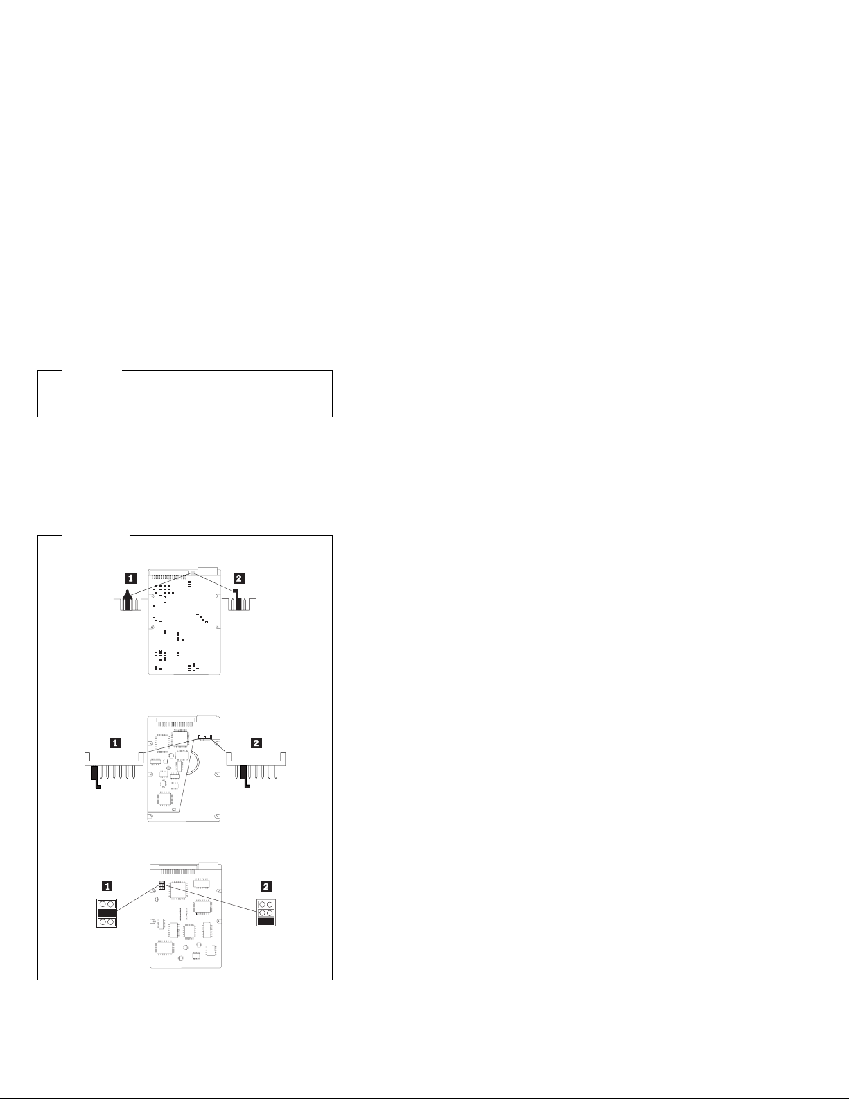
Hard disk drive jumper settings
IDE hard disk drives for the PC 300 series computers use
jumpers to set the drives as primary (master) or secondary
(slave).
Attention
For drives not shown below, refer to the label on the
hard disk drive for the hard disk drive settings.
IDE hard disk drive settings
.1/ Primary (Master) Hard Disk Drive
.2/ Secondary (Slave) Hard Disk Drive
IDE Drives
PC 300 - 6584/6594 51
Page 62

CD-ROM drive jumper settings
CD-ROM and PC/CD-ROM drives use jumpers or tabs to
set the drives as primary (master) or secondary (slave).
Refer to the drive connector labels or the figures below for
the drive settings.
AUDIO
RGGL
IDE INTERFACE
39
40
1
2
See Jumper
Settings Below
CD-ROM, PD/CD-ROM
Type
2X CD-ROM
FRU 06H5906
4X CD-ROM
FRU 06H7654
6X CD-ROM : : J : J :
8X CD-ROM : : J : J :
6X PD/CD-ROM : : J : J :
16X Max CD-ROM : : J : J :
24X Max CD-ROM : : J : J :
32X Max CD-ROM : : J : J :
40X Max CD-ROM : : J : J :
48X Max CD-ROM : : J : J :
Primary
Secondary
(Master)
: : J : : : J : : :
: : J : : : J : : :
DC INPUT
5V GG 12V
(Slave)
52 IBM PC 300/IntelliStation Vol 3 HMM
Page 63

BIOS levels
An incorrect level of BIOS can cause false error and
unnecessary FRU replacement. Use the following
information to determine the current level of BIOS installed
in the computer, the latest BIOS available for the
computer, and where to obtain the latest level of BIOS.
Current Level BIOS information.
– Run the Configuration Utility to determine the
level of BIOS installed.
Sources for determining the latest level BIOS
available.
1. IBM PC Company Home Page
http://www.ibm.com/pc/us/
2. PC PartnerInfo-Technical Database
(CTSTIPS.NSF)
3. Bulletin Board System (BBS)
4. HelpCenter
5. Levels 1 and 2 Support
6. RETAIN
Sources for obtaining the latest level BIOS available.
1. IBM PC Company Home Page
http://www.ibm.com/pc/us/
2. PC PartnerInfo-Technical Database
(CTSTIPS.NSF)
3. Bulletin board system (BBS)
4. HelpCenter
5. Levels 1 and 2 Support
To update (flash) the BIOS, see “Flash (BIOS/VPD) update
procedure” on page 54.
PC 300 - 6584/6594
53
Page 64

Flash (BIOS/VPD) update procedure
Attention
Refer to the information label located inside the
system unit cover for any model-specific information.
1. Power-off the computer.
2. Insert the flash update diskette into drive A.
3. Power-on the computer.
4. When the Update Utility appears; select your
country/keyboard, then press Enter.
5. If the computer serial number was previously
recorded, the number is displayed with an option to
update it. Press Y to update the serial number.
6. Type the 7-digit serial number of the computer you
are servicing; then, press Enter.
7. Follow the instructions on the screen to complete the
flash (BIOS/VPD) update procedure.
Flash recovery boot block
Attention
If an interruption occurs during a Flash/BIOS upgrade,
the BIOS might be left in an unusable state. The Boot
Block jumper enables you to restart the system and
recover the BIOS.
To perform a Flash/BIOS recovery using the recovery
jumper:
1. Power-off the computer and remove the cover.
2. Move the system board recovery jumper to the clear
position. Refer to “System board layout” on page 77
or the information label inside the computer for more
information.
3. Insert the upgrade diskette into the diskette drive.
4. Power-on the computer. The IBM Logo will appear.
5. When the Flash Update Utility appears; select your
country/keyboard, then press Enter.
6. If the computer serial number was previously
recorded, the number is displayed with an option to
update it. Press Y to update the serial number.
7. Type the 7-digit serial number of the computer you
are servicing; then, press Enter.
8. Follow the instructions on the screen to complete the
flash (BIOS/VPD) update procedure.
9. When you are instructed to reboot the computer,
power-off the computer and move the recovery
jumper to the normal position. Then, replace the
cover and power-on the computer.
54 IBM PC 300/IntelliStation Vol 3 HMM
Page 65

Power management
Power management reduces the power consumption of
certain components of the computer such as the system
power supply, processor, hard disk drives, and some
monitors. Advanced Power Management and Rapid
Resume Manager are features of some personal
computers.
Advanced Configuration and Power
Interface (ACPI) BIOS: Being an ACPI BIOS
system, the operating system is allowed to control the
power management features of the computer and the
setting for Advanced Power Management (APM) BIOS
mode are ignored. Not all operating systems support ACPI
BIOS mode.
Advanced Power Management: Energy-saving
settings can be viewed and changed by using the
Advanced Power Management menu in the
Configuration/Setup Utility program.
Attention
If a device, such as a monitor, does not have
power-management capabilities, it can be damaged
when exposed to a reduced-power state. Before
making energy-saving selections for the monitor,
check the documentation supplied with the monitor to
see if it supports Display Power Management
Signaling (DPMS).
Automatic Hardware Power Management
features: Automatic Hardware Power Management
can reduce the power states of the computer, processor,
and monitor (if monitor supports DPMS) if they are inactive
for a predetermined length of time.
There are three levels of specified time that the computer
must be inactive before the power management options
that are selected take effect. Select the amount of time
that is offered within each level.
Level 1 Set time from 5 minutes to 4 hours.
Level 2 Set time from 10 minutes to 5 hours.
Level 3 Set time from 15 minutes to 6 hours.
At each level, you can define the amount of energy
savings by specifying values for the following options:
System Power:
– Select On for the computer to remain on.
– Select Off for the computer to shut down.
Display:
PC 300 - 6584/6594
55
Page 66

Set display to be disabled or to be reduced at these
power states:
– Standby: Screen is blank, but can be restored
immediately when any activity is detected.
– Suspend: Monitor uses less power than in
Standby mode. Screen image is restored after a
few seconds when any activity is detected.
– Off: Monitor power is off. Press Monitor power
button to restore power. On some monitors, you
might have to depress the power button twice.
Setting Automatic Hardware Power
Management features
1. Start the Configuration/Setup Utility program (see
“Setup Utility program” on page 41).
2. Select Power Management from the
Configuration/Setup Utility program menu.
3. Select the APM BIOS Mode and be sure it is set to
Enabled. If it is not, press Left Arrow (←) or Right
Arrow (→) to change the setting.
4. Select Automatic Hardware Power Management.
5. Set Automatic Hardware Power Management to
Enabled.
6. Select values for the two levels of power
management (system power and display), as
necessary.
7. Set IDE Drives to Enabled or Disabled.
Note: This does not apply to SCSI drives.
8. Select Low Power Entry Activity Monitor and
enable or disable the listed options.
9. Select Low Power Exit Activity Monitor and enable
or disable the listed options.
10. Press Esc twice to return to the Configuration/Setup
Utility program menu.
11. Before you exit from the program, select Save
Settings from the Configuration/Setup Utility program
menu.
12. To exit from the Configuration/Setup Utility program,
press Esc and follow the instructions on the screen.
Automatic Power-On features: The Automatic
Power-On features within the Power Management menu
allow you to enable and disable features that turn the
computer on automatically.
Serial Port Ring Detect: With this feature set to
Enabled and an
port (COM1), the computer will turn on automatically
when a ring is detected on the modem.
56 IBM PC 300/IntelliStation Vol 3 HMM
external
modem connected to serial
Page 67

Modem Ring Detect: With this feature set to
Enabled, the computer will turn on automatically
when a ring is detected on the internal modem.
Wake Up on Alarm: You can specify a date and
time at which the computer will be turned on
automatically. This can be either a single event or a
daily event.
PCI Wake Up: PCI Wake Up uses PCI Power
Management Enabled (PME) to wake up the
computer when using token-ring, Ethernet LAN
adapters, modems, or other PCI cards capable of
waking up the computer. When you set PCI Wake
Up to Enabled, the computer will turn on when it
receives a specific signal from another computer on
when it receives a specific signal from another
computer on the local area network (LAN) or from a
modem signal.
Wake on LAN features can be used on the 6584 and
6594 computers. For further information, see “Wake
on LAN” on page 58.
Network settings
This section applies only to computers linked to a network.
The Configuration/Setup Utility program includes settings
that can be enabled and disabled to configure the network
interface in the computer. These settings are:
Flash over LAN (Update POST/BIOS over Network)
Wake on LAN
Flash over LAN (update POST/BIOS
over network)
Note: For local Flash (BIOS/VPD) update, see “Flash
(BIOS/VPD) update procedure” on page 54.
This setting is used to enable or disable the Flash over
LAN feature. When the feature is enabled, the system
programs, in the computer, can be updated remotely from
a network server. If the administrator password is set in
the computer, it does not have to be entered by the server.
To access the Flash over LAN setting:
1. Start the Configuration/Setup Utility program. See
“Setup Utility program” on page 41.
2. Select System Security.
3. Select POST/BIOS Update from the
Configuration/Setup Utility program menu.
4. To enable Flash over LAN, select Enabled.To
disable Flash over LAN, select Disabled.
5. Press Esc twice to return to the Configuration/Setup
Utility program menu.
PC 300 - 6584/6594
57
Page 68

6. Before you exit from the program, select Save
Settings from the Configuration/Setup Utility program
menu.
7. To exit from the Configuration/Setup Utility program,
press Esc and follow the instructions on the screen.
Wake on LAN
This setting is used to enable or disable the
IBM-developed Wake on LAN feature. This feature makes
it possible for the computer to be turned on remotely by a
network server. Remote network management software
must be used in conjunction with this feature.
To access the Wake on LAN setting:
1. Start the Configuration/Setup Utility program. See
“Setup Utility program” on page 41.
2. Select Advanced Power Management.
3. Select Automatic Power On from the program menu.
4. Select Wake on LAN from the Automatic Power On
menu.
5. To enable Wake on LAN, select Enabled. To disable
Wake on LAN, select Disabled.
6. Press Esc until you return to the Configuration/Setup
Utility program menu.
7. Before you exit from the program, select Save
Settings from the Configuration/Setup Utility program
menu.
8. To exit from the Configuration/Setup Utility program,
press Esc and follow the instructions on the screen.
58 IBM PC 300/IntelliStation Vol 3 HMM
Page 69

System board memory
The following matrix cross-references the name of the
computer (printed on the logo) and the size, speed, and
type of memory modules supported in the computer.
Note
RAMBUS inline memory module (RIMM) is used in the
type 6584/6594 computer. RIMM modules are not
compatible with SIMM or DIMM memory modules.
Refer to the information below regarding RIMM
memory for type 6584, 6594.
Computer
Name
PC 300
Type 6584/
6594
128 MB
256 MB
512 MB
Maximum
RIMM Memory Module
Size Memory Type
PC700/
PC800
PC800 only
RDRAM
ECC/
Non-ECC
Note
For maximum 512 MB configuration, two 256 MB
PC800 memory RIMMs must be installed. PC700
memory RIMMs can not be used.
Supported RIMM memory configuration
Type 6584/6594 has two RIMM memory sockets. RIMM
sockets must either have a RIMM memory module or a
C-RIMM (RIMM Continuity module) installed. There can
be no empty RIMM sockets. At least one socket must
have a RIMM memory module installed.
If new memory is to be added, remove a C-RIMM and
install the new RIMM.
If memory is to be removed, remove the RIMM and
install a C-RIMM.
RIMM sizes of 128 MB and 256 MB are acceptable.
RIMM sockets can be filled in any order. ECC or
non-ECC, RAMBUS dynamic random access memory
(RDRAM) are supported.
Note
Mixed RIMM speeds will run at the lower speed.
RIMM diagnostic approach
Identify any Beep or POST codes. See “Symptom-to-FRU
index” on page 82.
Use the IBM PC Enhanced Diagnostics program to run
memory tests. See “IBM PC Enhanced Diagnostics error
codes” on page 1.
PC 300 - 6584/6594
59
Page 70

Procedures to determine memory errors:
1. If a memory error occurs, and the system is
operational, run memory diagnostics.
2. If a memory error occurs, and the system is not
operational:
a. Remove one RIMM module at a time until the
system comes up.
Note
All unused RIMM sockets must have a
C-RIMM installed.
b. Run memory diagnostics.
c. Install the other RIMM and run diagnostics again
to identify the failing RIMM.
60 IBM PC 300/IntelliStation Vol 3 HMM
Page 71

Computer exploded view (Type 6584)
I/O connectors and removal procedures for the cover,
CD-ROM/hard drive bracket, CD-ROM drive, hard drive,
EIDE and SCSI cable routing, Diskette drive, system
board, riser card, power supply, and fan/speaker bracket
removal are on the following pages.
PC 300 - 6584/6594 61
Page 72

Input/Output connectors
Monitor
Parallel
USB 2
USB 1
Serial 2
2
2
1
1
Serial 1
Mouse
Keyboard
62 IBM PC 300/IntelliStation Vol 3 HMM
Page 73

Top and front cover removal
Pull
Latches
To remove top and front cover:
1. Pull left and right pull latches forward then pull cover
forward.
2. Lift cover up from the chassis.
To install top and front cover:
1. Slide cover down onto the chassis about 4-inches
(10.16 cm) from the rear of chassis.
2. Slide cover back to engage the left and right latches.
PC 300 - 6584/6594
63
Page 74

CD-ROM/hard drive bracket
To open the CD-ROM/hard drive bracket:
1. Remove the top cover.
2. Slide the plastic spring loaded cage retainer to the
left.
3. Lift the cage up and swing it back to the service
position.
CD-ROM drive removal
To remove the CD-ROM drive:
1. Remove the top cover.
2. Put the CD-ROM/hard drive bracket in its service
position.
3. Disconnect the CD-ROM signal and power cables.
4. Remove two screws securing the CD-ROM drive.
5. Pull the CD-ROM drive out of the bracket.
64 IBM PC 300/IntelliStation Vol 3 HMM
Page 75

Hard drive removal
To remove the hard drive:
1. Remove the top cover.
2. Put the CD-ROM/hard drive bracket in its service
position.
3. Disconnect the hard drive signal and power cables.
4. Push in on the left and right plastic tabs of the hard
drive rails.
5. Pull the hard drive out of the bracket.
Note
Remove the plastic rails from the old hard drive and
install them on the new hard drive.
EIDE cable routing
Primary
Secondary
SCSI cable routing
PC 300 - 6584/6594 65
Page 76

Diskette drive removal
To remove the diskette drive:
1. Remove the top cover.
2. Disconnect the diskette drive signal and power
cables.
3. Remove the front screw of the diskette drive cage.
4. Pull the diskette drive out of the chassis.
5. Remove the two side screws from the diskette drive
cage.
6. Remove the diskette drive from its cage.
66 IBM PC 300/IntelliStation Vol 3 HMM
Page 77

System board removal
Latch
System Board
Rail
Tab
Lift
Here
Lift
Here
Tab
System Board
To remove the system board:
1. Remove the top cover.
2. Remove all cables connected to the system board.
3. Remove the AGP card, if installed.
4. Remove the retainer side bracket thumb screw.
5. Swing open the retainer side bracket and remove it
from the chassis.
6. Lift up on the system board right-hand rail tab to
disengage it from the bottom of the chassis.
7. Rotate the latch handle to disengage the system
board.
System board installation
System Board
Push
Here
Hole
Tab
Tab
Pull
Here
Rotate the latch handle and firmly push in on the end of
the right-hand rail to engage the tab in the opening of the
chassis.
PC 300 - 6584/6594
67
Page 78

Riser card removal
To remove the riser card:
1. Remove the top cover.
2. Remove the system board.
3. Disconnect all cables from the front and back of the
riser card.
4. Remove the two top screws securing the riser card.
5. Remove the riser card from the chassis.
Power supply removal
Note
1. Make sure the power supply voltage switch is set
to the proper operating voltage; 115V or 230V.
To remove the power supply:
1. Remove the top cover.
2. Disconnect the power supply connectors.
3. Remove the four screws securing the power supply to
the chassis.
4. Move power supply inward, then lift out of the
chassis.
68 IBM PC 300/IntelliStation Vol 3 HMM
Page 79

Fan and speaker bracket removal
Note
1. If you remove the LED/power cable or the RFID
antenna cable, make sure it is routed the same
way it was installed.
2. When removing the C2 switch assembly from the
fan bracket, use care to pry the switch
(alternating at both ends of the switch) from its
mounting studs.
3. Make sure the RFID antenna cable is grounded
to the chassis by its grounding lug.
To remove the fan bracket:
1. Remove the top cover.
2. Remove the air duct.
3. Disconnect the fan and speaker connectors.
4. Push on the outside tab to release the bracket from
the chassis.
5. Swing the bracket inward and then pull it from the
chassis.
PC 300 - 6584/6594
69
Page 80

Computer exploded view (Type 6594)
I/O connectors and removal procedures for the access
cover, top handle cover, system board, hard disk drive,
tab, and fan cage, air baffle, and card guide are on the
following pages.
70 IBM PC 300/IntelliStation Vol 3 HMM
Page 81

Input/Output connectors
Microphone
Line In
Line Out
Parallel
USB 1
Serial 1
Keyboard
USB 2
2
1
1
Serial 2
2
Mouse
PC 300 - 6584/6594 71
Page 82

Access cover removal
CoverRelease
Tab
Socket7
Socket7
Unlock cover from back of the system unit before removing
cover.
Top handle cover removal
Attention
Do not lift handle cover too high or the tabs will break.
72 IBM PC 300/IntelliStation Vol 3 HMM
Page 83

Front bezel removal/replacement
PC 300 - 6584/6594 73
Page 84

System board removal
System Board
Rail
Lift
Here
Latch
Tab
Lift
Here
Tab
System board installation
System Board
Push
Here
Hard disk bracket removal
System Board
Tab
Hole
Pull
Here
Tab
74 IBM PC 300/IntelliStation Vol 3 HMM
Page 85
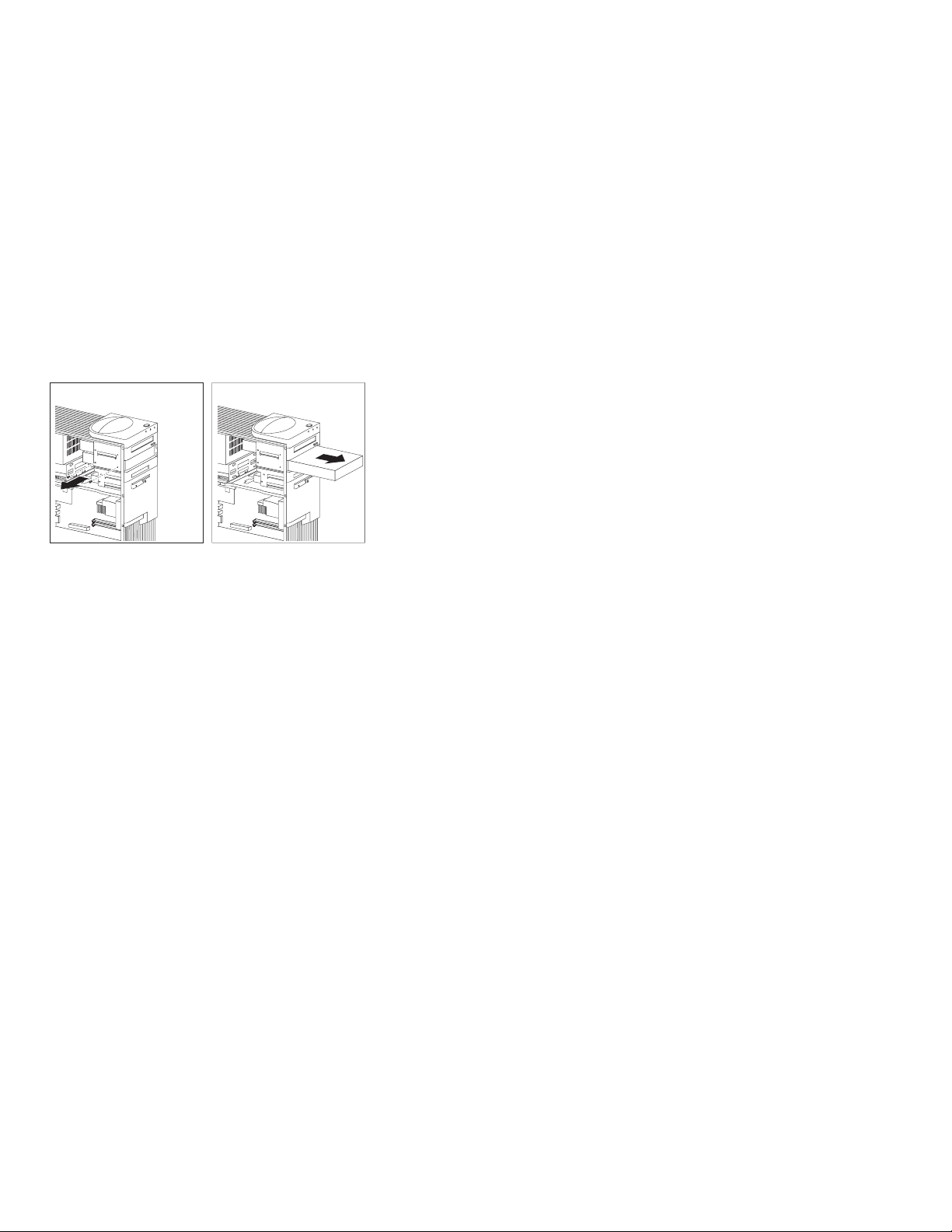
Hard disk drive in non removable drive
cage
PC 300 - 6584/6594 75
Page 86

Tab removal
Fan cage, air baffle, speaker/card guide
removal
Push in on the latches as shown by arrows to release the
fan cage, air baffle, or speaker/card guide.
Note
After releasing the latch on the speaker/card guide,
slide it away from the latch to disengage it from the
chassis.
76 IBM PC 300/IntelliStation Vol 3 HMM
Page 87

System board layout
123
System board locations
.1/ Processor fan connector (not used)
.2/ Processor socket
.3/ RIMM socket 1
.4/ RIMM socket 2
.5/ AGP connector
.6/ Battery
.7/ Keyboard/Mouse connectors
.8/ Serial 1,2 connectors
.9/ USB connectors
.1ð/ Recovery jumper
.11/ PC PCI connector (not used)
.12/ Parallel connector
.13/ Line Out connector
.14/ Line In connector
.15/ Microphone connector
PC 300 - 6584/6594
77
Page 88

System board jumper settings
The following table contains the jumper setting information.
(D) indicates the default setting.
Clear CMOS/Flash Boot Block Recovery
Use the recovery jumper setting to Clear CMOS or to
Flash Boot Block Recover.
Jumper Setting Description
Recovery 2-3 (clear)
1-2 (D)
(normal)
Processor Speed Settings
Processor speed for the PC 300 type 6584/6594
computers are fixed and are determined by the processor.
There are no settings required.
Diskette Write Access
Diskette Write Enable and Write Protect options are
changed in the Setup Configuration. See “Setup Utility
program” on page 41.
Clear CMOS/
Flash Recovery
Mode
Normal Mode
78 IBM PC 300/IntelliStation Vol 3 HMM
Page 89

Riser cards (Type 6584)
Riser card, ISA/PCI, front view
CD
Audio
ISA1
System Board
Connector
Power
Speaker
RFID
LEDs
Riser card, PCI, front view
CD
Audio
PCI
PCI1
ISA2
Tamper
Fan
Alert
on
LAN
SCSI
LED
Wake
on LAN
FDD
Connector
PCI
PCI2
PCI
PCI3
PCI
Power
LEDs
Alert
on
LAN
RFID
Speaker
Tamper
Fan
SCSI
LED
Wake
on
LAN
FDD Connector
PC 300 - 6584/6594 79
Page 90

Riser card, back view (both cards)
Power Connector
Primary IDE
Secondary IDE
80 IBM PC 300/IntelliStation Vol 3 HMM
Page 91

Riser card (Type 6594)
CD
Audio
System Board
Connector
Alert on LAN
Power
PCI
Diskette
IDE Secondary
IDE Primary
Hard Disk Fan 1
Hard Disk Fan 2
Front Fan
Power/LED
Wake
on LAN
RF ID
Speaker
Tamper
SCSI LED
PC 300 - 6584/6594 81
Page 92

Symptom-to-FRU index
The Symptom-to-FRU index lists error symptoms and
possible causes. The most likely cause is listed first.
Always begin with “General checkout” on page 24. See
“IBM PC Enhanced Diagnostics error codes” on page 1
when running diagnostics. This index can also be used to
help you decide which FRUs to have available when
servicing a computer. If you are unable to correct the
problem using this index, go to “Undetermined problem” on
page 104.
Notes
If you have both an error message and an
incorrect audio response, diagnose the error
message first.
If you cannot run the diagnostic tests or you get
a diagnostic error code when running a test, but
did receive a POST error message, diagnose the
POST error message first.
If you did not receive any error message, look for
a description of your error symptoms in the first
part of this index.
Check all power supply voltages before you
replace the system board. (See “Power supply”
on page 29.)
Check the hard disk drive jumper settings before
you replace a hard disk drive. (See “Hard disk
drive jumper settings” on page 51.)
Important
1. Some errors are indicated with a series of beep
codes. (See “Beep symptoms” on page 83.)
Type 6584/6594 computers default to come up
quiet (No beep and no memory count and
checkpoint code display) when no errors are
detected by POST. To enable Beep and memory
count and checkpoint code display when a
successful POST occurs:
Enable Power on Status in setup. See
“Setup Utility program” on page 41.
2. The processor is a separate FRU from the
system board; the processor is not included with
the system board FRU.
82 IBM PC 300/IntelliStation Vol 3 HMM
Page 93

Beep symptoms
Beep symptoms are short tones or a series of short tones
separated by pauses (intervals without sound). See the
following examples.
Beeps Description
1-2-X One Beep
4 Four continuous beeps
Beep Symptom FRU/Action
1-1-3
CMOS read/write error
1-1-4
ROM BIOS check error
1-2-X
DMA error
1-3-X 1. RIMM Memory
1-4-4 1. Keyboard
1-4-X
Error detected in first 64 KB
of RAM.
2-1-1, 2-1-2 1. Run Setup
2-1-X
First 64 KB of RAM failed.
2-2-2 1. Video Adapter
2-2-X
First 64 KB of RAM failed.
2-3-X 1. Memory Module
2-4-X 1. Run Setup
3-1-X
DMA register failed.
3-2-4
Keyboard controller failed.
A pause (or break)
Two beeps
A pause (or break)
Any number of beeps
1. Run Setup
2. System Board
1. System Board
1. System Board
Module
see“System board
memory” on page 59
2. C-RIMM
3. System Board
2. System Board
1. Memory Module
2. System Board
2. System Board
1. Memory Module
2. System Board
(if installed)
2. System Board
1. Memory Module
2. System Board
2. System Board
2. Memory Module
3. System Board
1. System Board
1. System Board
2. Keyboard
PC 300 - 6584/6594 83
Page 94

Beep Symptom FRU/Action
3-3-4
Screen initialization failed.
3-4-1
Screen retrace test detected
an error.
3-4-2
POST is searching for video
ROM.
4 1. Video Adapter
All other beep code
sequences.
One long and one short
beep during POST.
Base 640 KB memory error
or shadow RAM error.
One long beep and two or
three short beeps during
POST.
(Video error)
Three short beeps during
POST.
Continuous beep. 1. System Board
Repeating short beeps. 1. Keyboard stuck key?
1. Video Adapter
(if installed)
2. System Board
3. Display
1. Video Adapter
(if installed)
2. System Board
3. Display
1. Video Adapter
(if installed)
2. System Board
(if installed)
2. System Board
1. System Board
1. Memory Module
2. System Board
1. Video Adapter
(if installed)
2. System Board
1. See “System board
memory” on page 59.
2. System Board
2. Keyboard Cable
3. System Board
No beep symptoms
Note
Type 6584/6594 computers default to come up quiet
(No beep and no memory count and checkpoint code
display) when no errors are detected by POST.
To enable Beep and memory count and checkpoint
code display when a successful POST occurs:
Enable Power on Status in setup. See “Setup
Utility program” on page 41.
Symptom/Error FRU/Action
No beep during POST but
computer works correctly.
84 IBM PC 300/IntelliStation Vol 3 HMM
1. System Board
Page 95

Symptom/Error FRU/Action
No beep during POST. 1. See “Undetermined
problem” on
page 104.
2. System Board
3. Memory Module
4. Any Adapter or Device
5. Riser Card
6. Power Cord
7. Power Supply
PC 300 - 6584/6594 85
Page 96

POST error codes
In the following index, “X” can represent any number.
POST Error Code FRU/Action
000
SCSI Adapter not enabled.
02X 1. SCSI Adapter
08X
Check SCSI terminator
installation.
101
System board interrupt
failure.
102
System board timer error.
106 1. System Board
110
System board memory
parity error.
111
I/O channel parity error.
114
Adapter ROM error.
129
Internal cache test error.
151
Real-time clock failure.
161
Bad CMOS battery.
1. Verify adapter device
and Bus Master fields
are enabled in PCI
configuration
program. See
documentation
shipped with
computer.
1. SCSI Cable
2. SCSI Terminator
3. SCSI Device
4. SCSI Adapter
1. System Board
1. System Board
1. Memory Module
2. System Board
1. Reseat adapters
2. Any Adapter
3. Riser card
4. System Board
1. Adapter Memory
2. System Board
3. Riser card
1. Processor
2. L2 Cache Memory
3. System Board
1. System Board
1. Run Setup
2. CMOS Backup Battery
(See page “Safety
information” on
page 332.)
3. System Board
86 IBM PC 300/IntelliStation Vol 3 HMM
Page 97

POST Error Code FRU/Action
162
Configuration mismatch.
162
And unable to run
diagnostics.
163
Clock not updating or invalid
time set.
164
POST detected a base
memory or extended
memory size mismatch
error.
or
RIMM socket 3 is populated
with a RIMM memory
module.
166
Boot Block Check Sum
Error
167
Microprocessor installed
that is not supported
by the current POST/BIOS.
1. Run Setup and verify
2. Had a device been
3. Power-on external
4. CMOS Backup Battery
5. System Board
6. Riser card
1. Diskette Drive
2. System Board
3. Diskette Drive Cable
4. Riser card
1. Time and Date Set?
2. CMOS Backup Battery
3. System Board
1. Run Setup. Check
2. Run the Extended
3. Replace RIMM
1. Run Flash Recovery
2. System Board
1. Run Setup. Check
2. Processor
Configuration
added, removed,
changed location? If
not, suspect that
device.
devices first, then
power-on computer.
(See page “Safety
information” on
page 332.)
(See page “Safety
information” on
page 332.)
System Summary
menu for memory
size change. (See
“Setup Utility
program” on
page 41.)
Memory Diagnostic
tests.
memory module in
socket 3 with a
C-RIMM
using Boot Block.
See “Flash recovery
boot block” on
page 54
Stepping level for the
BIOS level needed,
then perform the
flash update.
PC 300 - 6584/6594 87
Page 98

POST Error Code FRU/Action
168
Alert on LAN2 error
17X, 18X 1. C2 Security
175 1. Run Configuration
176 1. Covers were removed
177
Corrupted Administrator
Password.
178 1. System Board
183 1. Enter the
184
No RFID Antenna
185
Corrupted boot sequence.
186 1. System Board
187 1. Clear Administration
189 1. More than three
190
Chassis intrusion detector
was cleared.
This is information only, no
action required.
If this code does not clear:
1XX
Not listed above.
201, 20X
Memory data error.
225 1. Unsupported Memory
1. Run Setup. Check to
see that Ethernet and
Alert on LAN2 are
enabled.
2. System Board
3. Riser card
(See “Setup Utility
program” on
page 41.)
2. System Board
from the computer.
1. System Board
administrator
password
1. Make sure Asset
Care and Asset ID
are enabled in
Configuration/Setup.
2. RFID Antenna
3. System Board
4. Riser card
1. Set configuration and
reinstall the boot
sequence.
password
2. System Board
password attempts
were made to access
the computer.
1. System Board
1. System Board
1. Run Enhanced Diag.
Memory Test
2. Memory Module
3. System Board
88 IBM PC 300/IntelliStation Vol 3 HMM
Page 99

POST Error Code FRU/Action
229
External cache test error.
262
POST detected a base
memory or extended
memory type error.
301 1. Keyboard
303
With an 8603 error.
303
With no 8603 error.
3XX
Not listed above.
5XX 1. Video Adapter
601 1. Diskette Drive A
602 1. Bad Diskette ?
604
And able to run diagnostics.
605
POST cannot unlock the
diskette drive.
662 1. Diskette drive
1. L2 Cache Memory
2. System Board
1. Run Setup. Check
System Summary
menu for memory
type change. (See
“Setup Utility
program” on
page 41.)
2. Run the Extended
Memory Diagnostic
tests.
2. Keyboard Cable
3. System Board
1. Mouse
2. Keyboard
3. Keyboard Cable
4. System Board
1. Keyboard
2. Keyboard Cable
3. System Board
1. Keyboard
2. Keyboard Cable
3. System Board
(if installed)
2. System Board
2. Diskette Drive Cable
3. System Board
4. Riser card
2. Verify Diskette and
retry.
1. Run Setup and verify
diskette configuration
settings
2. Diskette Drive A/B
3. Diskette Drive Cable
4. System Board
5. Riser card
1. Diskette Drive
2. Diskette Drive Cable
3. System Board
4. Riser card
configuration error or
wrong diskette drive
type, run Setup
Configuration.
PC 300 - 6584/6594 89
Page 100

POST Error Code FRU/Action
6XX
Not listed above.
762
Math coprocessor
configuration error.
7XX
Not listed above.
962
Parallel port configuration
error.
9XX 1. Printer
1047 1. 16-Bit AT Fast SCSI
107X
Check SCSI terminator
installation.
1101
Serial connector error,
possible system board
failure.
1101, 1102, 1106,
1108, 1109
1107 1. Communications
1102
Card selected feedback
error.
1103
Port fails register check.
1106
Serial option cannot
be turned off.
1107 1. Serial Device Cable
1110
Register test failed.
1116
Interrupt error.
1. Diskette Drive
2. System Board
3. Riser card
4. External Drive Adapter
5. Diskette Drive Cable
6. Power Supply
1. Run Setup
2. Processor
3. System Board
1. Processor
2. System Board
1. Run Configuration
2. Parallel Adapter
(if installed)
3. System Board
2. System Board
Adapter
1. Check SCSI
terminator
installation.
2. SCSI Cable
3. SCSI Terminator
4. SCSI Device
5. SCSI Adapter
1. Run Enhanced
Diagnostics
1. System Board
2. Any Serial Device
Cable
2. System Board
1. Run Enhanced
Diagnostics
1. Run Enhanced
Diagnostics
2. System Board
1. Run Enhanced
Diagnostics
2. System Board
2. System Board
1. Run Enhanced
Diagnostics
2. System Board
1. Run Enhanced
Diagnostics
90 IBM PC 300/IntelliStation Vol 3 HMM
 Loading...