

Page 1

Hardware Maintenance Service
for Service Lev el A
Machine Type 6832/6833
Page 2

First Edition (March, 2001)
The following paragraph does not apply to any state
or country where such provisions are inconsistent
with local law: INTERNATIONAL BUSINESS
MACHINES CORPORATION PROVIDES THIS
PUBLICATION “AS IS” WITHOUT WARRANTY OF
ANY KIND, EITHER EXPRESSED OR IMPLIED,
INCLUDING, BUT NOT LIMITED TO, THE IMPLIED
WARRANTIES OF MERCHANTABILITY OR
FITNESS FOR A PARTICULAR PURPOSE.
References to IBM products, programs, or services
do not imply t hat IBM intends to make them available
outside the United St ates. This publication could
include technical inaccuracies or typographical
errors. Changes are periodically made to the
information herein; these changes will be made in
later editions. IBM may make improvements and/or
changes in the product(s) and/or the program(s) at
any time. Addr ess com ments abo ut t his pu blica tion t o
IBM Corporation, Dept. E23/962-2, 455 Park Place,
Lexington, KY 40511-1856, USA. Information you
supply may be used by IBM without obligation. For
copies of publications related to thi s product, call toll
free 1-800-IBM-7282 in the Continental U.S.A. In
Canada, call toll free 1-800-465-7999.
© Copyright International Business Machines
Corporation 2001.
All rights reserved.
Note to U.S. Government Users - Documentation
related to restricted rights - Use, duplication or
disclosure is subject to restri ctions set forth in GSA
ADP Schedule Contract with IBM Corp.
Page 3

Contents
Contents ..............................................................iii
Notices ............. ............ ............... .............. .......... vii
Safety Information ................................................viii
Laser Co m p lia n c e Stat ement .. ......... .......... ........x x xi
Trademarks ....................................................... xxxii
Preface .... ... .... ..... ... ..... .... ..... ... ..... .... ..... ... ..... ... xxxiii
Genera l In fo r m a ti o n .. .. .......... ......... .......... .......... .. 1
Introduction ............................................................2
Product Overview ...... ................................... .. ........3
Process or ............. .............. ...................... ....... 3
Memory ........................................................... 3
External Ports .................................................. 4
Diskette Drive ..................................................4
Hard Disk Drive ...............................................4
DVD-ROM Drive ..............................................5
Multime dia .... .......... .......... ....... .......... .......... ....5
Power Management ........................... .. ...........5
Power Supply ............................. ........... .. .. ......6
Internal Cabling ...............................................6
Keyboard ......................................................... 6
Mouse ............................................................. 6
Hardware Interfaces ...............................................7
CMOS Res e t .. ... .......... ......... ................. .......... ....... 9
User Password .....................................................10
Flash (BIOS) Upda te P ro c e dure ......... ................. 1 1
BIOS Co nf ig u ration/Se tu p Ut ilit y .. ......... .......... .....12
Working with the Configuration/Setup
Utility M e nu .. ... .. .......... .......... ......... .......... .....12
Main Menu ......... ............ ...............................13
Advanc ed Me nu ....... ... .. .......... .......... .......... .. 16
Security Menu ......... .. ....................................20
Power Menu ................... ............. .............. ....21
Boot Menu .......... ................................... .. .. ....21
Exit Menu ......................................................21
Specific ations . ........ ......... .......... ....... .......... .......... 2 3
Dimension (widt h x depth x height) ............ .. .23
Weight . .............. ............ ............... ............... .. 23
Environment . ............... .............. ............. ....... 23
Power consumption ....................................... 23
Electrical input .............. .................................23
Operating Requir e m e n ts . ... ................. .......... .......24
iii
Page 4

Check P ro c ed ur e s . ... .. ................. .......... .......... .. 2 5
Introduction .......................................................... 26
Start .....................................................................27
Index of Symptoms, Messages, Error Codes,
or Beeps ............. .. ............................................. ...32
Troubleshooting ...................................................48
Factor y- In s ta ll e d S to r age De v ic e s ...... ... .. .....48
Factory-I nstalled Modem Card ....................... ......52
Audio (Not Supported by Diagnostics Program) ..54
CD/DVD - R OM D riv e ................. .......... .......... ....... 5 7
Memory ............. .............. ............. .............. .......... 59
Keyboard .............................................................. 60
Mouse .................................................................. 61
Power Supply ........ .. .............. ...............................63
Monitor ..................... ...................... ............ .......... 66
Undetermined Prob lems ........ .. .. ......................... .68
Diagnostic Aids .................................................. 71
Introduction .......................................................... 72
Power-O n S e lf T est ..... ......... .......... .......... .......... .. 7 3
Diagnostic Diskette .................. .............. ........... ...75
Using the Diagnosti c Diskette .......................75
Using Diagnostic Pr ogram from
Recovery CD ................................................. 76
Diagnos tics Prog ram Fe a tu r e s .. .......... .......... 77
Repair In fo r m a t io n .... ......... .......... .......... .......... .. 8 1
Remova ls and R ep la c e me n ts ... .......... .......... .......82
Handling ESD-Sensitive Parts .............................83
Cover .......... .......... ......... ................. .......... .....86
Bay Pane ls ... ... ......... .......... .......... .......... .......88
Bay 1 and 2- 5.25-In. Bay
(Internal or External Access) .........................89
Bay 3 - 3.5-I n. Bay
(Internal or External Access) .........................90
Bay 4 - 3.5-I n. Bay
(External Access for Diskette Drive) .............91
Front Panel .......... ..........................................95
Power Supply ............... .. ......................... ......96
AGP Card ...................................................... 99
Adapter Cards .............................................100
Memory(RIMM) ........................................... 101
Intel Pent iu m 4 Wil la m e tt e Pro c e s sor .... .. ... 1 0 4
System B a cku p Ba tt e ry . .......... .......... .......... 1 0 6
Indica to r LED a n d Ca bl e .... ................. ........107
iv
Page 5

System B o a rd .. ......... .......... .......... .......... .....108
Parts/Test Point Locations ..............................111
Introduction ........................................................ 112
System Board Jumpers and Connectors ..........113
Power Supply Connecto rs and Vol tages ...........115
Network Cards ................................................... 118
Factory-I nstalled Modem Card Layout ...............119
Video Cards .......................................................120
Nvidia TNT2 M64, 32MB .............................120
Nvidia GeForce2 GTS Pro NV15, 64MB .....121
ATI RADEON, 32MB (US) .......................... 121
ATI RADEON, 32MB (EMEA) ..................... 122
1394 Card ..........................................................124
3.5-In. Hard Disk Drive Jumper Settings ............ 125
CD-ROM Drive ...................................................127
CD-ROM Drive Rear Panel Connectors
and Jumpers ...............................................129
CD-ROM R/W Drive ...........................................130
CD-ROM R/W Drive Rear Panel
Connectors and Jumpers ............................ 131
DVD-ROM Drive .......................................... 132
DVD-ROM Drive Rear Panel Connectors
and Jumpers ...............................................133
RIMM Configurations .........................................134
System Board Connector Pin Si gnals .............. ..135
Monitor Port Signals .................................... 135
Serial Port Signals .......................................135
Parallel Port Signals .................................... 136
Mouse Port Signals ..................................... 136
Keyboard Port Signals ......... .. ............ .. .......136
Diskette Drive Cable Connector Signals .....137
IDE Cable Connector Signals .....................138
Safety In s p ec t io n Guide .............. .......... .......... 1 3 9
General Guidelines ............................................140
6832 Parts Catalog ...........................................141
Abbreviations ..................................................... 142
System Assembly ..............................................143
Assembly 1: System Unit ............................143
Assembly 2: Diskette and Hard Drive .........145
Assembly 3: CD/DVD-ROM Drive,
Adapter Ca r d a nd S pe a k e r ..... ................. ... 146
Assembly 4: Power Cord .............................148
Assembly 5: Keyboard and Mouse ............. 149
v
Page 6

Assembly 6: Recovery CD ..........................151
6833 Parts Catalog ...........................................153
Abbreviations ..................................................... 154
System Assembly ..............................................155
Assembly 1: System Unit ............................155
Assembly 2: Diskette and Hard Drive .........157
Assembly 3: CD/DVD-ROM Drive,
Adapter Ca r d a nd S pe a k e r ..... ................. ... 158
Assembly 4: Power Cord .............................159
Assembly 5: Keyboard and Mouse ............. 160
Assembly 6: Recovery CD ..........................162
6832 Appendix A. FRU Number List ...............163
6833 Appendix A. FRU Number List ...............167
Appendix B. Online Support Information ......171
Index .. ... ..... .... ... ..... ..... .... ... ..... ..... .. ..... ..... ..... .. ...173
vi
Page 7

Notices
References in this publication to IBM produc ts,
programs, or ser vices do not imply that IBM intends
to make these avail able in all countries in which I BM
operates. Any r eference to an IBM product , program,
or service is not intended to state or imply that only
IBM's product, program, or service may be used. Any
functionally equivalent produ ct, program, or service
that does not infringe any of IBM's intellectual
property rights, or other legally pr otectable rights,
may be used instead of the IBM product, program, or
service. References in this publication to IBM
products, programs, or services are purely hardwarerelated and do not cover circumstances of software
problems. Evaluation and verification of operation in
conjunctio n wit h othe r product s, pr ogram , or serv ices,
except those expressly designated by IBM are the
user's responsibility.
IBM may have patents or pending patent applications
coveri ng su b je c t m a tt er in th is doc u m e n t. T he
featuring of these patents, pending or otherwise, in
this document does not give you any license to these
patents. You can send li cense inquires, in writ ing, to
the IBM director of Commercial Relations, IBM
Corporation, Purchase, NY10577.
Voltage Supply Switch Settings
Your IBM Personal Computer might have voltage
switches, whi ch must be set correctly for your voltage
supply. If your monitor or system unit has a voltage
switch, complete these steps to make sure each
switch is set correctly:
1. Determine the correct voltage switch setting for
your area:
Voltage Supply Range Voltage Switch Setting
100-12 7 V 115 V
200-24 0 V 230 V
2. Locate the voltage switch on the back of your
monitor or syste m unit. If the setting shown on the
switch is:
•
Correct: start setting up your IBM computer.
•
Incorrect: change the voltage switch setting.
Notices vii
Page 8

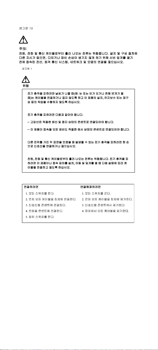
Safety Information
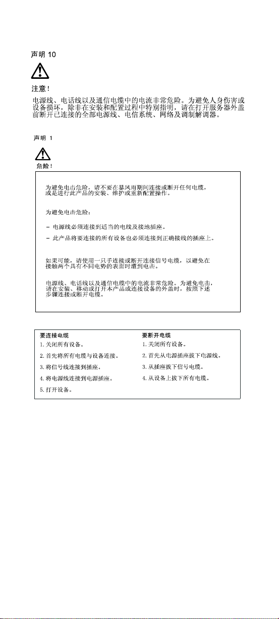
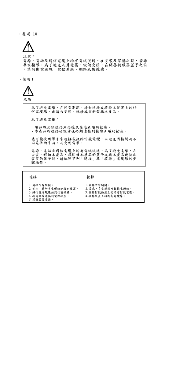
DANGER
To avoid a shock hazard, do not connect or
disconnect any cables or perform installation,
maintenance, or reconf igurati on of this product during
an electrical storm.
To avoid shock hazard:
•
The power cord must be connected to a properly
wired and grounded receptacle.
•
Any equipment to which this product will be
attached must al so be con nected to properl y wired
receptacles.
When possible, use one hand to connect or
disconnect si gnal cables to prevent a poss ible shock
from touching two surfaces with different electrical
potentials.
Electrical cur rent from power, telephone, and
communications cable s is hazardou s. To avoi d shock
hazard, connect and disconnect cables as described
following when installing, moving, or opening covers
of this product or at tached devices.
To Connect
1. Turn Everything OFF.
2. First, attach all cables to
devices.
3. Attach signal cables to
receptacles.
4. Attach power cord(s) to
outlet.
5. Turn device ON
To Disconnect
1. Turn Everything OFF.
2. First, remove power
cord(s) from outlet.
3. Remove signal cables
from receptacles.
4. Remove all cables from
devices.
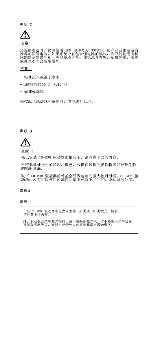
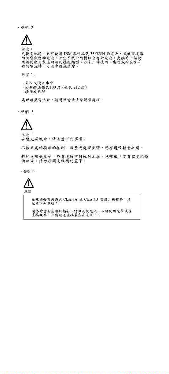
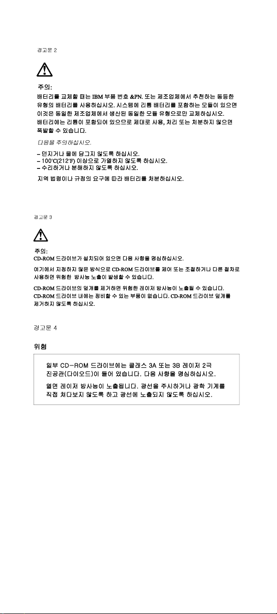
IMPORTANT:
When replacing the battery , use only IBM Part
Number 33F8354 or an equivalen t type battery
recommended by the manufacturer. If your
system has a module containing a lithium
battery, replace it only with the same module
type made by the same manufacturer. The
viii
Page 9

battery contains lithium and can explode if not
properly used, handled, or disposed of.
Do not:
•
Throw or immerse into water
•
Heat to more than 100°C (212°F)
•
Repair or disassemble
Dispose of the batter y as required by local ordinances
or regulations.
IMPORTANT:
When a CD-ROM drive is installed, note the following.
Use of controls or adjustments or perfor ma nce of
procedures other than those specified herein might
result in hazardous radiation exposure.
Removing the covers of the CD-ROM drive could
result in exposur e to hazardou s laser ra diation. Ther e
are no serviceable parts inside the CD-ROM dri ve.
Do not remove the CD-ROM drive covers .
DANGER
Some CD-ROM drives contain an embedded Class
3A or Class 3B laser diode. Note the followi ng.
Laser radiation when open. Do not stare into the
beam, do not view directl y with optical instrum ents,
and avoid direct exposure to the beam.
IMPORTANT:
Electrical cur rent from power, telephone, and
communication cables can be hazardous. To avoid
personal i njury or equipment damage, d isconnect the
attached power cords, telecommunications systems,
networks, and modem s before you open the server
covers, unles s instructed otherwise i n the i n stallation
and configuration procedures.
Notices ix
Page 10

PERIGO:
Para evitar choq ues elétricos, não conec te ou
desconecte nenhum cabo, nem efetue instala ção,
manutenção ou reconfiguração deste prod uto
durante uma tempestade com raios.
Para evitar choq ues elétricos:
•
O cabo de alimentação deve ser conectado a um
receptáculo corretamente instalado e aterrado.
•
Todos os equipamentos aos quais este produt o
será conectado devem também ser conectados a
receptáculos corretamente instalados.
Quando possível, utilize uma das mãos para
conectar ou desconectar cabos de sinal, para evitar
um possível choque ao tocar duas superfícies com
potenciais elétricos diferentes.
A corrente elétri ca proveniente de cabos de
alimentação, de telefone e de comunicação é
perigosa. Para evitar choques elétricos, conecte e
desconect e os cabos conforme descrito a seguir, ao
instalar, movimentar ou abr ir tampas deste produto
ou de dispositivos conectados.
Para Conectar
1.DESLIGUE tudo.
2.Conecte primeiro tod os
oscabos nosdispositivos.
3.Conecte os cabos de sinal
nos receptáculos.
4.Conecte o(s) cabo(s) de
alimentação nas
tomadas.
5.LIGUE o dispos itivo
x
Para Desconectar
1.DESLIGUE tudo.
2.Remova primeiro o(s)
cabo(s) de alimentação
das tomadas.
3.Remo va os cabo s de si nal
dos receptáculos.
4.Remova todos os cabos
dos dispositivos
Page 11

CUIDADO:
Ao substituir a bat eria, utilize apenas o Número de
Peça IBM 33F8354 ou um tipo de bat eria equ ivale nte
recomendado pelo fabricante. Se seu sistema
possuir um módulo com uma bateria de lítio,
substitua-o apenas pelo mesmo tipo de módulo,
produzido pelo mesmo fabricante. A bateria contém
lítio e pode explodir se não for utilizada, manuseada
e descartada de forma adequada.
Não:
•
Jogue ou coloque na água
•
Aqueça a mais de 100°C (212°F)
•
Conserte nem desmonte.
Descarte a bateria conforme requerido pelas
disposições e regulamentações locais.
CUIDADO:
Quando uma unidade de CD-ROM estiver instalada,
observe o seguint e.
A utilização de controles ou ajustes ou a execução de
procedimentos diferentes daqueles especificados
nesta publicação pode resultar em exposição
perigosa à radiação.
A remoção das tampas da unidade de CD-ROM pode
resultar em exposição a radiação perigosa de laser.
Não existem peças que possam ser consertadas no
interior da unidade de CD-ROM. Não re mov a as
tampas da unidade de CD-ROM.
PERIGO:
Algumas unidades de CD-ROM cont ém um diodo de
laser da Classe 3A ou da Classe 3B. Obser ve o
seguinte.
Radiação de laser quando aberto. Não olhe
diretamente para o feixe de laser, não olhe
Not ic es xi
Page 12

diretamente com instrumentos óticos, e evite
exposição direta ao raio.
CUIDADO:
A corrente elétri ca proveniente de cabos de
alimentação, de telefone e de comunicação é
perigosa. Para evitar ferimentos pessoais ou danos
aos equipamentos, desconecte os cabos de
alimentação, sistemas de telecomunicação, redes e
modems antes de abrir as t amp as do servidor, a
menos que receba outras instruções nos
procedimentos de instalação e configuração.
xii
Page 13
Notices xiii
Page 14
xiv
Page 15
Notices xv
Page 16
xvi
Page 17

PERIGO:
Pour éviter tout risque de choc électrique, ne
manipulez aucun câble et n'effectuez aucune
opération d'installation, d'entretien ou de
reconfiguration de ce produit au cours d'un orage.
Pour éviter tout risque de choc électrique :
•
Les cordons d'alimentation du présent produit et
de tous les apparei ls qui lui sont conne ctés doivent
être branchés sur des socles de prise de coura nt
correctement câblés et mis à la terre.
Afin d'éviter tout risque de choc électrique provenant
d'une différence de potentiel de terre, n'utilisez
qu'une main, lorsque cela est possible, pour
connecter ou déconnecter les cordons d'interface.
Le courant élect rique passant dans les câbl es de
communication, ou les cordons téléphoniques et
d'alimentati on peut être dangereux. Pour éviter tout
risque de choc élec tr ique, lorsque vous installez ou
que vous déplacez le pr ésent produit ou des
périphéri ques qui lui sont raccordés, reportez-vous
aux instructions ci-dessous pour connecter et
déconnecte r le s différents cor dons.
Connexion
1. Mettez les unit és hors
tension.
2. Commencez par
brancher tous les
cordons sur les unités.
3. Branchez les câbles
d'interface sur les prises.
4. Branchez les cordons
d'alimentation sur un
socle de prise de
couran t.
5. Mettez les unit és sous
tension.
Déconnexion
1. Mettez les unités hors
tension.
2. Commencez pas
débrancher les cordons
alimentation des socles
de prise de courant.
3. Débranchez les câbles
d'interface des p rises.
4. Débranchez tous les
câbles des unités.
Not ic es xvii
Page 18

ATTENTION:
Remplacez la pile usagée par une pile de référence
identique exclusivement - voir la référence IBM - ou
par une pile équivalente recommandée par le
fabricant. Si votre système est doté d'un modul e
contenant une pile au li thium, vous devez le
remplacer uniq uem ent par un module identique ,
produit par le même fabricant. La pile contient du
lithium et présente donc u n risque d'explos ion en cas
de mauvaise manipulation ou utilisation.
•
Ne la jetez pas à l'eau.
•
Ne l'exposez pas à une température supérieure à
100°C.
•
Ne cherchez pas à la répare r ou à la démont er.
Pour la mise au rebut, reportez-vous à la
réglementation en vigueur.
ATTENTION:
Si une unité de CD-ROM est installée, prenez
connaissance des informations sui vantes :
Pour éviter tout ri sque d'exposition au rayon laser,
respectez les consignes de réglage et d'utilisation
des commandes, ainsi que les procédures décrites
dans le présent document.
Pour éviter une exp osition directe au rayon l aser,
n'ouvrez pas l'unité de CD-ROM. Vous ne pouvez
effectuer aucune opération de maintenance à
l'intérieur.
PERIGO:
Certaines unités de CD-ROM contiennent une diode
laser de classe 3A ou 3B. Prenez connaissance des
informati ons suivantes :
Rayonnement laser lorsque le carter est ouvert.
Évitez de regard er fixement le faisceau ou de
xviii
Page 19

l'observe r à l'aide d'instruments optiques. Évitez une
exposition directe au rayon.
ATTENTION:
Le courant électrique circulant dans les câbles de
communication et les cordons téléphoniques et
d'alimentati on peut être dangereux. Pour votre
sécurité et ce ll e de l'équipement, avant de ret irer les
carters du serv eur, mettez celui-ci hors tension et
déconnectez ses cordons d'alimentation, ainsi que
les câbles qui le relient aux réseaux, aux systèmes
de télécommunication et aux modems (sauf
instruct ion contr aire ment ionnée dans les procédu res
d'installation et de configuration)
.
Notices xix
Page 20

VORSICHT:
Aus Sicherheitsgründen bei Gewitter an diesem
Gerät keine Kabel anschließen oder lösen. Ferner
keine Installations-, Wartungs- oder
Rekonfigurationsarbeiten durc hführen.
Aus Sicherheitsgründen:
•
Gerät nur an eine Schutzkontaktsteckdose mit
ordnungsgemäß geerdetem Schutzkontak t
anschließen.
•
Alle angeschlossenen Geräte ebenfalls an
Schutzkontaktsteckdosen mit ord nungsgemäß
geerdetem Schutzkontakt anschlie ßen.
Signalkabel möglichst einhändig anschließen oder
lösen, um einen Str om schlag durch Berühren von
Oberflächen mit unterschiedlichem elektrischem
Potential zu vermeiden.
Elektrische Spannungen von Netz-, Telefon- und
Datenübertragungsleitungen sind gefährlich. Um
einen Stromschl ag zu vermeiden, nur nach den
Anweisungen arbei ten, die für Installati on, Transport
oder Öffnen von Gehäusen dieses Produkts oder
angeschlossenen Einheiten gelten.
Kabel anschließen
1.Alle Geräte ausschalten
und Netzstecker ziehen.
2.Zuerst alle Kabel an
Einheiten anschließen.
3.Signalkabe l an
Anschlußbuchsen
anschließen.
4.Netzstecker an Steckdose
anschließen.
5.Ger ät ei ns ch al t e n.
xx
Kabel lösen
1.Alle Geräte ausschalten.
2.Zuerst Netzstecker von
Steckdose lösen.
3.Signalkabe l von
Anschlußbuchsen lösen.
4.Alle Kabel von Einheiten
lösen.
Page 21

ACHTUNG:
Eine verbraucht e Batterie nur durch eine Batterie mit
der IBM Teilenummer 33F8354 oder durch eine vom
Hersteller empfohlene Batterie erset zen. Wenn Ihr
System ein Modul mit einer Lithium-Batterie enthält,
ersetzen Sie es immer mit dem selben Modultyp vom
selben Hersteller. Die Batterie enthält Lithium und
kann bei unsachgemäßer Verwendung, Handhabung
oder Entsorgung explodieren.
Die Batterie nich t
•
mit Wasse r in Berührung bringen.
•
über 100 C erhitzen.
•
reparieren oder zerlegen.
Die örtlichen Best imm ungen für die Entsorgung von
Sondermüll beachten.
ACHTUNG:
Wenn ein CD-ROM-Laufwerk installiert ist, beachten
Sie folgendes. Steuer- und Einstellelemente sowie
Verfahren nur entsprechend den Anweisungen im
vorliegenden Handbuch einsetzen. Andernfalls kann
gefährliche Laserstrahlung auftreten.
Das Entfernen der Abdeckungen des CD-ROMLaufwerks kann zu gef ährlicher Laserstrahlung
führen. Es befinden sich keine Teile innerhalb des
CD-ROM-Laufwerks, die vom Benutzer gewartet
werden müssen. Die Verkleidung des CD-ROMLaufwerks nicht öffnen.
VORSICHT:
Manche CD-ROM-Laufwerke enthalten eine
eingebaute Laser diode der Klasse 3A oder 3B. Die
nachfolgend aufgeführten Punkte beachten.
Laserstrahlung bei geöffneter Tür. Niemals direkt in
den Laserstrahl sehen, nicht direkt mit optischen
Notices xxi
Page 22

Instrumenten betrachten und den Strahlungsbereich
meiden.
ACHTUNG:
An Netz-, Telefon- und Datenleitungen können
gefährliche elektrische Spannungen anliegen. Um
eine Gefährdung des Benutzers oder Beschädigung
des Geräts zu vermeiden, ist der Server
auszuschalten. Die Verbindung zu den
angeschlossenen Netzkabeln,
Telekommunikationssystemen, Netzwerken und
Modems ist vor dem Öffnen des Servergehäuses zu
unterbrechen (sofern in Installations- und
Konfigurationsanweisungen nicht anders angegeben)
PERICOLO:
Per evitare il per icolo di scosse elettriche durante i
temporali, non collegare o scollega re cavi, non
effett uare l'installaz ione, la manutenzione o la
riconfigurazione di questo prodotto.
Per evitare il per icolo di scosse elettriche:
•
collegare il cavo di alimentazione ad una presa
elettrica corr ettamente cablata e muni ta di terra di
sicurezza;
•
collegare qualsiasi apparecchiatura collegata a
questo prodotto ad una presa elettrica
correttamente cablata e munita di terra di
sicurezza.
Quando possibile, collegare o scollegare i cavi di
segnale con una sola mano per evitare il rischio di
scosse derivant i dal contatto con due superfici a
diverso potenziale elettrico.
La corrente elettrica circolante nei cavi di
alimentazi one, del telefono e di segnale è pericolosa.
Per evitare scos se elettriche, collegare e scollegare
xxii
Page 23

icavi come descri tto quando si effettuano
l'install azione, la rimozione o l' apertura dei coperch i
di questo prodotto o durante il collegamento dell e
unità.
Per collegare
1.SPEGNERE tutti i
dispositivi.
2.Collegare prima tutti I cavi
alle unit à.
3.Collegare i cavi di segnale
alle prese.
4.Collegare il(i) cavo(i) di
alimentazione alla presa
elettrica.
5.ACCENDERE le unità.
Per scollegare
1.SPEGNERE tutti i
dispositivi.
2.Rimuovere prima il(i)
cavo(i) di alimentazione
dalla presa elettrica.
3.Rimuovere i cavi di
segnale dalle prese.
4.Rimu overe t utt i i cavi da lle
unità.
ATTENZIONE:
Quando si sostit uisce la batteria, uti lizzare solo una
batteria IBM o batterie dello stesso ti po o di ti po
equivalent e consigliate dal produtt ore. Se il sistema
di cui si dispone è provvisto di un modulo contenente
una batteri a al litio, sostituire tale batter ia solo con un
tipo di modulo uguale a quello fornito dal produttore.
La batteri a cont iene l iti o e può es plo dere se util izzat a,
maneggiata o smalti ta impropriamente.
Evitare di:
•
Gettarla o immergerla in acqua
•
Riscaldarla ad una t emperatura s uperiore ai 100° C
•
Cercare di ripararla o smaltirla
Smaltire se condo la nor mativa i n vig ore (D. Lgs 22 del
5/2/97) e successive disposizioni nazionali e locali.
Notices xxiii
Page 24

ATTENZIONE:
Quando è installata un'unità CD-ROM, notare quanto
segue:
L'utilizz o di controlli, regolazioni o l'esecuzione di
procedure non descritti nel presente manuale
possono provocare l'esposizione a radiazioni
pericolose.
L'apertura di un'unità CD-ROM può determinare
l'esposi zione a radiazioni laser pericolose. All'interno
dell'unità CD-ROM non vi sono parti su cui effettuare
l'assistenza tecnica. Non rimuovere i coperchi
dell'unità CD-ROM.
PERICOLO:
Alcune unità CD-ROM contengono all'interno un
diodo laser di Classe 3A o Classe 3B. Prestare
attenzione a quanto segue:
Aprendo l'unità vengono emesse radiazioni laser.
Non fissare il fascio, non guardarlo direttamente con
strumenti ottici ed evitare l'esposizione diretta al
fascio.
ATTENZIONE:
La corrente circolante nei cavi di alimentazione, del
telefono e di segnale è pericolosa. Per evit are
situazioni pericolose per le persone o
danneggiamen ti all'apparecchiatura, scoll egare i cavi
di alimenta zione, i si stemi di tel ecomuni ca zioni , le r eti
e ed i modem prima di aprire i coper chi del servente
se non diversamente indicato nelle procedure di
installazione e configurazio ne.
xxiv
Page 25
Notices xxv
Page 26
xxvi
Page 27

PELIGRO:
Para evitar una pos ibl e descarga eléctrica, no
conecte ni desconecte los cables ni lleve a cabo
ninguna operación de instalación, de mantenimiento
o de reconfigura ción de este producto durante una
tormenta eléctrica.
Para evitar una pos ibl e descarga:
•
El cable de alimentación debe conectarse a un
receptáculo con una instalación eléctrica correcta
y con toma de tierra.
•
Los aparatos a los que se cone cte este producto
también deben estar conectados a receptáculos
con la debida instalación eléctrica.
Cuando sea posible, utilice una sola mano para
conectar o desconectar los cables de señal a fin de
evitar una posible descarga al tocar dos superficies
con distinto potencial eléctrico.
La corriente eléctrica de los cables de
comunicaciones, teléfono y alimentación puede
resultar peligrosa. Para evitar una posible descarga,
siga las indicaciones de conexión y desconexión de
los cables siempr e que tenga que instalar, mover o
abrir las cubiertas de este producto o de los
dispositivos acoplados.
Instrucciones de
conexión
1.Apague todos los
componentes (OFF).
2.En primer lugar, conecte
todos los cables a los
dispositivos.
3.Conecte los cables de
señal a los receptáculos.
4.Conecte los cables de
alimentación a las tomas.
5.Encienda el dispositivo
(ON).
Instrucci one s de
desconexión
1.Encienda todos los
componentes (ON).
2.En primer lu gar, retire los
cables de alimentación de
las tomas.
3.Ret ire los ca bles de señal
de los receptáculos.
4.Retire todos los cables de
los dispositivos.
Notices xxvii
Page 28

IMPORTANT:
Al cambiar la baterí a, utilice únicamente l a bater ía
IBM Número de pieza 33F8354 o un tipo de batería
equivalent e recomendado por el fabricante. Si el
sistema tiene un módulo que contie ne una baterí a de
litio, sustitúyalo únicamente por el mismo tipo de
módulo del mismo fabr icant e. La ba tería conti ene li tio
y puede explotar si no se utili za, manipula o desecha
correctamente.
Lo que no debe hacer
•
Tirar o sumergir el producto en agua.
•
Exponer el product o a una temperatura superi or a
100°C.
•
Reparar o desmontar el producto.
Cuando quiera desechar la batería, siga la s
disposici ones y reglamentaci ones locales.
IMPORTANT:
Cuando instale una unidad de CD-ROM, tenga en
cuenta la siguiente información.
Si se llevan a cabo controles o ajustes o se utili zan
métodos que no se atengan a lo aquí especificado,
se puede producir una exposición peligrosa a las
radiaciones.
Si se retiran las cubiertas de la unidad de CD-ROM,
se puede producir una peligrosa exposición a
radiaciones de láser. Dentro de la unidad de CDROM no existen piezas reparables. No retire las
cubiertas de la unidad de CD-ROM.
PELIGRO:
Algunas unida des de CD-ROM ti enen incor porado un
diodo de láser de Clase 3A o de Clase 3B Tenga en
cuenta la siguiente información.
xxviii
Page 29

Cuando la unidad est á abierta se generan emisiones
de rayos láser. No dirija la mirada al haz, no lo
observe direct am ente con instrumentos ópticos y
evite la exposición directa.
IMPORTANT:
La corriente eléctrica de los cables de
comunicaciones , de teléf ono y de aliment ación puede
resultar peligrosa. Para evitar posibles lesiones o
daños del aparato, desconecte los cables de
alimentaci ón, los sistemas de telec om unicaciones,
las redes y los módem s antes de abrir las cubiertas
del servidor, salvo que se indique lo contrario en las
instrucci ones de las operaciones de instalación y
configuración.
Notices xxix
Page 30

Laser Compliance Statement
The CD-ROM drive in the computer is a laser
product. The CD-ROM drive' s classification label
(sample shown below) is l ocated on the drive.
CLASS 1 LASER PRODUCT
APPAREIL A LASER CLASSE 1
LASER KLASSE 1
LUOKAN 1 LASERLAITE
PRODUIT LASER
CATEGORIE 1
The CD-ROM drive is certified in the U.S. to conform
to the requirements of the Department of Health and
Human Services 21 Code of Federal Regulations
(DHHS 21 CFR) Subchapter J for Class 1 laser
products.
In other countries, the drive is certifi ed to conform to
the requirements of EN60825.
Class 1 laser products are not considered to be
hazardous. The CD-ROM drive has an internal Cl ass
1, 0.5-milliwatt, aluminum gallium-arsenide laser that
operates at a wavelength of 760 to 810 manomet ers.
The design of the laser system and the CD-ROM
drive ensures t hat there is no exposure to laser
radiation above a Class 1 level during normal
operation, user maintenance, or s ervi cing conditions .
xxx
Page 31

Trademarks
The following are tr adem arks of the IBM Corporation
in the United States or other countries or both:
AT
HelpCenter
IBM
Operating System/2
OS/2
Personal System/ 2
PS/1
PS/2
Intel, Pentium, MMX, Ether Express, and LANDesk
are trademarks or registered trademar ks of Intel
Corporation.
Microsoft, MS- DO S, W indows, and Windows NT are
trademarks or re gistered trademarks of Microsoft
Corporation.
Other company, product, and service names may be
trademarks or ser vice marks of others.
Notices xxx i
Page 32

Preface
This manual c ont ains s ervic e inf ormatio n for the
& 6833 Service Level A (SL-A)
Personal Computer, worldwide. This manual is
intended to be used as a stand-alone document to
service machine type 6832 & 6833 products. It is
divided into the following chapters:
Notices
notices required to service this comp uter.
Genera l In fo r m a ti o n
this manual.
Check Procedures
instruct ions that aid in locating the fa il ing Field
Replaceable Unit (FRU).
Diagnostic Aids
tools for isolating failures.
Repairing Information
descripti ons to disassemble and reassemble the
computer.
Parts/T est Poi nt Location s
descripti ons of the locations of the major parts,
jumpers, and connectors.
Safety Inspect ion Guide
inspecting a machine for safety problems before
putting the machine under a Maintenance
Agreement.
Parts Catalog
and part numbers for individual FRUs.
Appendix A, FRU Number Index
numbers listed in numerical order.
contains import ant safety information and
contains a brief description of
provides step- by-step
explains how to use the diagno stics
contains illustrations and
contains descrip ti ons, illustrati ons,
model of the IBM
contains illustrati ons and
contains information about
contains part
6832
xxxii
Page 33

General Information
Introduction ............................................................2
Product Overview ...... ................................... .. ........3
Process or ............. .............. ...................... ....... 3
Memory ........................................................... 3
External Ports) ................................................4
Diskette Drive ..................................................4
Hard Disk Drive ...............................................4
DVD-ROM Drive ..............................................5
Multime dia .... .......... .......... ....... .......... .......... ....5
Power Management ........................... .. ...........5
Power Supply ............................. ........... .. .. ......6
Internal Cabling ...............................................6
Monitor (Not included with some models) .......6
Keyboard ......................................................... 6
Mouse ............................................................. 6
Hardware Interfaces ...............................................7
CMOS Res e t .. ... .......... ......... ................. .......... ....... 9
User Password .....................................................10
Flash (BIOS) Upda te P ro c e dure ......... ................. 1 1
BIOS Co nf ig u ration/Se tu p Ut ilit y .. ......... .......... .....12
Working with the Configuration/
Setup Uti lity Menu .... .......... .......... .......... .......12
Main Menu ......... ............ ...............................13
Advanc ed Me nu ....... ... .. .......... .......... .......... .. 16
Security Menu ......... .. ....................................20
Power Menu ................... ............. .............. ....21
Boot Menu .......... ................................... .. .. ....21
Exit Menu ......................................................21
Specific ations . ........ ......... .......... ....... .......... .......... 2 3
Dimension (widt h x depth x height) ............ .. .23
Weight . .............. ............ ............... ............... .. 23
Environment . ............... .............. ............. ....... 23
Power consumption ....................................... 23
Electrical input .............. .................................23
Operating Requir e m e n ts . ... ................. .......... .......24
General Information 1
Page 34

Introduction
This chapter giv es a general o vervi ew of t he Personal
Computer Type 6832 and 6833, describes the
standard and optional features, and detail s its
functional and environmental specifications.
2 IBM Desktop System HMM
Page 35

Product Overview
Personal Computer Type 6832 and 6833 has thr ee
PCI slots and supports the Pentium 4 Willamette
processor family with Socket W processor package
type.
The Personal Computer Type 6832 and 6833
supports Accel erated Graphics Port (AGP) 2X / 4X,
which allows installed system memory to be used as
texture memory, yielding a huge texture footpri nt to
enhance 3D graphical display performance.
Listed below are 6832 and 6833 system features:
Processor
•
Socket W connector.
•
Detachable CPU fan sink.
•
128 KB of on-chip level one (L1) cache
•
256 KB level two (L2) ca che s upport for Wil lamett e
•
Intel Pentium 4 Williamette processor; 400MHz
front side bus, 1.30/ 1.40/1.50GHz, Stre aming
SIMD Extensions 2 (SSE2) extends MMX
SSE technology
•
Dual channel RDRAM
TH
and
Memory
•
184-pin Direct Rambus Dynam ic Random Access
Memory (DRDRAM), Rambus in-line Memory
Module (RIMM) sock ets.
- 4 RIMM sockets.
- 64MB, 128MB and 256MB RIMM.
- PC-133, 2.5V, capable of delivery up to 1.6GB
per second, 8-layer, oper ating at 800MHz, 16-bi t/
serial data output speed with gold contacts
- Maximum memory is 1.5GB
RDRAM
Technology
64MB 16MB 512MB
128MB 32MB 1GB
256MB 64MB 1.5GB
Increments
Maximum
(2 channels)
General Information 3
Page 36

Externa l P o rt s
•
One multi-mode parallel port (25-pin D-type
connector)
•
One serial port (9-pi n D-sub connector)
•
One keyboard port and one mouse port
•
Four USB ports (2 on port bracket , the other 2 on
the front panel)
•
One Game/MIDI port (15-p in D-sub connector)
•
Microphone-in jack
•
Speaker-out jack
•
Line-in jack
•
One floppy port (up to 2.88MB, 3 mode support)
Diskette Drive
•
One external 3.5 “ drive for 2.88MB, 1.44MB or
720KB diskette
•
Two 5. 25” drives for 1.2MB or 360KB diskette
•
Support 3-mode drive
Hard Disk Drive
•
3.5-in., 1-i n. hei ght IDE drive. (3.5-in may be in
acoustic mounti ng bracket), and 7200rpm.
•
128 KB “look-ahead” cache memory inside the
hard disk drive .
•
Average and minimum 12 ms seek ti m e, access
time varies for the har d disk drive and the hard
disk drive manufacturer.
4 IBM Desktop System HMM
Page 37

DVD-ROM Drive
•
5.25-in. high-performance, 8X/40X DVD-ROM
IDE/AT drive.
•
Read data and audio play from standard, mini
DVD-ROM and audio compact discs (audio CDs).
DVD media supported on DVD models.
Multimedia
•
A pair of external active speakers with a power
adapter or a pair of passi ve speakers.
•
Noise canceling microphone available.
Power Management
•
Support ACPI (Advanced Conf igurati on and Power
Interface) power management.
•
ACPI v1.04 and APM v1.2 compliant
•
CPU clock throttli ng and clock stop control for
complete ACPI S3 state suppor t
•
PCI bus clock run, Power Management enable
(PME) control, PCI/CPU color generator stop
control.
•
Power-on Switch must support Soft-Off and
Full-Off.
- Touch for 1 second or less to put system on
Suspend state.
- Touch and hold for 4 seconds to put system on
Full-Off state (Po we r Suppl y standby remains).
•
System enters stand by mo de if any of f o llowing
conditions ar e met:
- Execute standby fro m Wind ows 98 Star t menu
- Pre ss sys te m pow e r bu tto n if it is se t to act as
standby functi on
- System is idle and the standby timer set in the
Windows 98 Power Management Property
elapses
•
8 bytes of BIOS scratch register
General Information 5
Page 38

Power Supply
•
PC-98 compatible 200W ATX power supply
•
Switchable high/l ow voltage selection
Internal Cabling
•
Two 40- pin ribbon cables for hard di sk drives and
CD/DVD-ROM drive.
•
One 34-pin ribbon cable for A T diskette drive.
•
One 4-pin (2-wire) cabl e for hard disk drive
light-emi tting diode (LED).
•
One 3-pin (3-wire) cabl e for power light-emit ti ng
diode (LED).
•
One 2-pin (2-wire) cabl e for power switch.
Keyboard
•
104-key, rubber dome Rapid Access™III E
keyboard with 1.8-m (5. 8-ft.) cable
•
104-key, PC Next Lite Chicony™ keyboard with
1.8-m (5.8-ft.) cable
Mouse
•
2 Button PS/2 Logitech™ mouse with 1.8-m (5.8ft.) cable
•
3 Button USB ScrollPoint™ III mouse with 1.8-m
(5.8-ft.) cable
6 IBM Desktop System HMM
Page 39

Hardware Interfaces
The following peripheral interfaces for adapters,
options, and drives are supported in the system unit.
Item Interface
Expans ion slot for
I/O adapter cards
Hard disk drives Two Dual Channel Bus Master IDE
DVD- RO M dr i ve 5.2 5- i n. high-pe rforman ce , 8X/ 4 0X
Diske t te dri v e AT diskette in terface
Video Physic al inte rface i s compatible with
Modem
(only for 6832)
Audio Compatible to AC’97
Pointing device IBM PS/2-compatible mouse
Keyboar d device IBM PS/2-compatib le keyboard
Serial port Support on e hig h s pe ed N S 16 C55 0
Three PCI (Peripheral Component
Interconnect) v2.2 compatible
expansion slots that operates at 33
MHz bus speed.
ports support Ult ra ATA/100, PIO
Mode 3/4, ATAPI IDE CD-ROM, CDR, CD-RW, and LS120.
DVD-ROM IDE/AT drive.
Support Bootable CD-ROM Format
specification version 1.0.
Compliant to Audio-CD, Video-CD,
CD-ROM/XA, Karaoke-CD, and
Photo-CD (both single and multisession) format.
the IBM Personal System/2 (PS/2)
VGA interface.
Support Accelerated Graphics Port
(AGP)
One 56.6 Kbps PCI modem adapter
card with data/fax features.
compatible UART s with send/receive
16 bytes FIFOs
RS232D electric al interface
compliant
General Information 7
Page 40

Item Interface
Parallel port Supports SPP (IBM PC/XT, PC/AT,
Game port Game port interface for joystick. It
USB Supports Universal UHCI
PS/2) compatible, EPP (IEEE 1284
compliance), ECP (IEEE 1284
compliance) interface.
IEEE 1284 compliant
also su pp or t s MIDI.
Specification for USB 1.1
8 IBM Desktop System HMM
Page 41

CMOS Reset
This system does not deny access to Configuration/
Setup Utility, if Supervis or Password is not set.
Execute “Load Setup Defaul t” in BI O S Confi guration/
Setup Utility to cle ar the corrupted CMOS data. See
“Load Setup Defaults” on page 21.
General Information 9
Page 42

User Password
A user password denies access to the system by an
unauthorized user when the system is powered on.
When a user password is active, the password
prompt appears on the screen each time the system
is powered on. The system starts after the proper
password is entered. See “User Password” on page
20 for more information about how to change, remove
and set password in Configuration/Setup Utility.
In some cases, you might be required to service a
system with an active and unknown user password.
To clear a password from the system, follow these
steps.
1. Turn of f system unit.
2. Unplug power cable from the el ectrical outlet.
IMPORTANT:
power cord plugged into the electrical outlet.
The power supply maint ains +5 Vdc of sta ndby
power when the power cord is plugged.
System damage might result if the power cord
is not unplugged during jumper setting.
3. Set JP20 to 2-3 position t o clear BIOS setting as
original manufacture setting. See “System Board
Jumpers and Connectors” on page 1 13.
IMPORTANT:
must enter a password in the Configuration/Set up
Utility. If Enhance d Security is enabled and the
password is forg ott en, the system board must be
replaced.
Do not attempt these steps with the
To reinstall the password, the user
10 IBM Desktop System HMM
Page 43

Flash (BIOS) Update Procedure
1. Prepare a bootable DOS diskette wi th
PHLASH16.EXE, and one XXXXXXX.WPH files
NOTE:
2. Insert the disket te and boot from drive A.
WARNING:
3. At the DOS prompt, type
4. The program updates the BIOS automatically.
WARNING:
5. Power o ff system after the BIOS is com p letel y
The PHLASH16.EXE is flash ut ility pr ograms.
The XXXXXXX.WPH is BIOS source code
binary file.
Do not boot with any memory related
driver such as HIMEM.SYS, EMS.SYS....
A:> PHLASH16
XXXXXXX.WPH
BIOS is programming, or the flash ROM will be
destroyed.
updated.
then press
Do not turn off th e system power while the
Enter
.
General Information 11
Page 44

BIOS Configuration/Setup Utility
Main Advanced Security Power Boot Exit
IBM BIOS Version P9KT05AUS
Language: [English (US)]
System Time: [XX:XX:XX]
System Date: [XX/XX XXXX]
Legacy Diskette A: [1.44/1.25MB 3 ½”]
Legacy Diskette B: [Disabled]
♦
Primary Master [40982MB]
♦
Primary Slave [None]
♦
Secondary Master [CD-ROM]
♦
Secondary Slave [None]
System Memory: 127MB
F1:Help
↓↓↓↓↑↑↑↑
Up/Down Enter:Select Sub-Menu ESC:Exit
-/+:ChangeValues F9:Setup Defaults F10:Save&Exit
↵↵↵↵
Select Menu
The Configuration/Setup Utility lets you rev iew and
change importan t informati on about the com puter and
its hardware.
Working with the Configuration/Setup
Utility Menu
Starting the Configuration/Setup Utility
Follow these ste ps to enter Setup when the comput er
is off:
1. Turn on you r monitor.
2. Press and hold F1.
3. Turn on the system unit.
If you have previo usly set a password, you are
prompted to type in the password after you press the
F1
key. Refer to the Configuration/Setup Utility Main
Menu below.
The following t abl e li sts spe cifi c keys o n t he keyboar d
that will help you move t hrough the Configuration/
Setup Utility Menus :
Keys Function
F1 Pres s t h is key if you wa nt he lp f or a
selected menu option.
12 IBM Desktop System HMM
Page 45

Keys Function
Down- or uparrow key
Enter Press this key to choose a
Esc After vi ewi ng or ma ki ng ch ange s t o
-/+ Press this key if you want to
F9 Restore setup defaults
F10 Press this key if you want to save
<-- Select menu
Use these arrow keys to go up and
down for highlighting an option on
the menu. (Press the Enter key to
choose the option.)
highlighted option from a menu, or
select sub-menu.
the settings on a menu, press this
key to exit the menu.
collap se / e xtend ite ms
and exit the current settings for a
line
Changing Parameter Settings
In the Configuration/Setup Utility Menus, the
configuration information that you can change is
enclosed in brackets like these: [ ]. You cannot
change any informat ion that is not enclosed in
brackets or is shown in grey instead of black color.
Use the up- or down- arrow keys to highlight options
then press
the setting of a particular parameter, highlight the
setting then use th e left- or r ight- arrow key to change
the setting. Refe r to the Confi guration/Setup Utility
help for details on the configurable parameters in
each menu.
Enter
to display a menu. When changi ng
Main Menu
To view general hardware information about your
computer, select the Configuration/Setup Utility Main
Menu.
Setup automatic ally updates this menu when you do
either of the followi ng:
•
Add or change hardware on your computer
•
Make changes to other me nus in Setup and save
General Information 13
Page 46

those changes
To view the computer information such as the BIOS
Version, System Time, System Date, and Diskette A,
B, the items are conf i gured and sho wn aut omatical ly.
For language disp layed, you can choo se from English
(US), Spanish, French, Deutsch, Italian, Netherlands
and Japanese. The default language is English (US).
In Main Menu, you can also find further information
for drivers as below.
Primary Master
Type
Default is Au to .
Multi-Sector Transfers
Default is 16 sectors.
LBA Mode Control
Default is Enabled.
32 Bit I/O
Default is Disabled.
Tr ansfer Mode
Default is Fa s t PI O 4
Ultra DMA Mode
Default is Mode 5.
Primary Slave
Type
Default is Disabled.
Multi-Sector Transfers
Default is Disabled.
LBA Mode Control
Default is Disabled.
14 IBM Desktop System HMM
Page 47

32 Bit I/O
Default is Disabled.
Tr ansfer Mode
Default is Standard.
Ultra DMA Mode
Default is Disabled.
Secondary Master
Type
Default is Au to .
Multi-Sector Transfers
Default is 16 sectors.
LBA Mode Control
Default is Enabled.
32 Bit I/O
Default is Disabled.
Tr ansfer Mode
Default is Fa s t PI O 4
Ultra DMA Mode
Default is Mode 2.
Secondary Slave
Type
Default is Disabled.
Multi-Sector Transfers
Default is Disabled.
LBA Mode Control
Default is Disabled.
General Information 15
Page 48

32 Bit I/O
Default is Disabled.
Tr ansfer Mode
Default is Standard.
Ultra DMA Mode
Default is Disabled.
Advanced Menu
If you want to see advanc ed inf ormation of the
system, such as C ache Memory, PCI Devi ce details,
enter Advanced Menu to identify or verify the settings
in the computer.
Plug & Play O/S
Plug & Play O/S can work, if the OS is Windows 95/
98 or 2000. The default is No.
Reset Configuration Data
This parameter will enable BIOS to reset
configuration data. The default is No.
Legacy USB Support
This parameter will enable or disable USB device
operation in DOS environment. The default is set to
Enabled.
Default Primary Video Adapter
The default primary video adapter for the system is
PCI.
Boot-time Diagnostic Screen
This parameter can enable or disable diagnostic
screen during boo t- time. The default is Disabled.
QuickBoot Mode
This parameter can enable or di sable qui ck boot func tion. The default is Enabled.
NumLock
This parameter can set ON or OFF the number lock
function. The default is ON.
16 IBM Desktop System HMM
Page 49

Advanced Chipset Control
This sub-menu displays information of graphics
aperture and memory gap.
Graphics Aperture
This parameter shows the size of graphics aperture.
Enable Memory Gap
This parameter ena bles or disables memory gap
function. The defaul t is Disabled.
Cache Memory
This sub-menu shows information of cache memory
size, cache vid eo, cache base, and cache extended
memory area.
Memory Cache
This parameter ena bles or disables memory cache
function. The default is Enabled.
Cache System BIOS Area
This parameter has options of Write Protect or
uncached options. The default is Writ e Prot ect.
Cache Video BIOS Area
This parameter has options of Write Protect or
uncached options. The default is Writ e Prot ect.
Cache Base 0-512K
This parameter has options of Write Protect or
uncached options. The default is Writ e Prot ect.
Cache Base 512K-640K
This parameter has options of Write Protect or
uncached options. The default is Writ e Prot ect.
Cache Extended Memory Area
This parameter has options of Write Protect or
uncached options. The default is Writ e Prot ect.
Cache A000-AFFF
The default is Disabled.
General Information 17
Page 50

Cache B000-BFFF
The default is Disabled.
Cache C800-CBFF
The default is Disabled.
Cache CC00-CFFF
The default is Disabled.
Cache D000-D3FF
The default is Disabled.
Cache D400-D7FF
The default is Disabled.
Cache D800-DBFF
The default is Disabled.
Cache DC00-DFFF
The default is Disabled.
Cache E000-E3FF
The default is Disabled.
Cache E400-E7FF
The default is Disabled.
Cache E800-EBFF
The default is Disabled.
Cach e E C 00-EFFF
The default is Disabled.
I/O Device Configuration
This sub-menu shows information of large disk
access mode, local bus IDE adapter, serial port,
parallel port, floppy disk controller and audio.
Large Disk Access Mode
The default is DOS. The other opti on is Ot her.
18 IBM Desktop System HMM
Page 51

Local Bus IDE Adapter
The available options are Both, Disabled, Primary
and Secondary. The default is Both.
Serial Port A
The available options are Auto, Disabled and
Enabled. The default i s Auto.
Parallel Port
The available options are Enabled, Auto and
Disabled. The default is Enabled.
Base I/O Add re s s
The available options are 378, 278, and 3BC. The
default is 378.
Interrupt
The available opti ons are IRQ7 and IRQ 5. The
default is IRQ7.
Mode
The available options are ECP, Output Only, Bidirectional and EPP. The default is ECP.
DMA Channel
The available options are DMA3 and DMA1. The
default is DMA3.
Floppy Disk Controller
The available options are Enabled, Disabled and
Auto. The default is Enabled.
Base I/O Add re s s
The available options are Primary and Secondary.
The default is Primary.
Audio
The available optio ns are Enabled and Disabled. The
default is Enabled.
PCI Device, Slot #1/Slot #2/Slot #3
This sub-menu shows information of Option ROM
Scan, Enable Master, and latency Timer.
General Information 19
Page 52

Option ROM Scan
The options ar e Enabled an d Disabl ed. Defau lt val ue
is Enabled.
Enable Master
The options ar e Enabled an d Disabl ed. Defau lt val ue
is Disabled.
Latency Timer
The options are Default, 0020h, 0040h, 0060h,
0080h, 00A0h, 00C0h and 00E0h. Default value is
Default.
Security Menu
If you want to see informat ion of password, such as
Supervisor Pass word, User Password , enter Secu rity
Menu to review the setti ngs in the computer.
Supervisor Password
This parameter is Clear, if you didn’t setup any
Supervisor Password.
Set Supervisor Password
For setting supervi sor passwo rd, cl ick Ent er . Another
Sub-Menu will show, ask you to key-in new password
twice. Once done, pre ss Esc return to Security
Menu.
Clear All Password
Press Enter to clear all password settings.
User Password
This parameter is Clear, if you didn’t setup any user
password.
Set User Password
For setting use r password, click Enter. Another SubMenu will show, ask you to key-in new password
twice. Once done, pre ss Esc return to Security
Menu.
20 IBM Desktop System HMM
Page 53

Password on Boot
This paramete r wil l enab le or di sable check passwor d
when booting the syst em . The default is Disabled.
Power Menu
There is only one parame ter in this menu. The
parameter disable or enable power savings. Default
is Disabled.
Boot Menu
This menu shows information regarding system boot.
Exit Menu
If you want to setup exit procedures, choose Exit
Menu. There are Exit Saving Changes, Exit
Discarding Changes, Load Setup Defaults, Discard
Changes, and Save Changes.
Exit Savin g Changes
After changing any parameter in the Setup
Configuration setting, return to Confi guration/Setup
Utility Exit Menu and select Exit Saving Changes to
save all the setti ngs you have changed. Click Yes, to
save the configu ration changes and exit.
Exit Disca rdi ng C ha n ge s
Press Esc to return to the Main Menu when you hav e
finished viewing settings and maki ng changes. Then,
Select Exit Menu, from this location, you can cho ose
Exit Discarding Changes to exit Setup but without
saving your changes.
Load Setup Defaults
The computer is already configured for use. The
original configuration settings, also called factory or
default setti ngs, are stored in the CMOS. Setup
includes an option Load Setup Defaults that lets you
reload the original configuration at any time.
To load the default set tings, follow these st eps:
1. Use down-arrow k ey to s elect Load Setup Def ault s
in Exit Menu. A dialog box appea rs confirming if
you want to load the default settings.
2. Use the left-arrow key to select Yes, the n press
Enter.
3. Press Esc to exit Setu p.
General Information 21
Page 54

A dialog box appears confirming if you want to
save the settin gs (i n this case, the default set tings
that you reloaded).
4. Use the left-arrow key to select Yes, the n press
Enter to exit.
You must load the Setup default settings in the
following instances:
•
When you replace the system battery.
•
When you customize the system configurati on
settings and some resource assignments conflict
causing the computer to stop responding.
Discard Changes
Select this par amet er, there wi ll be another sub-menu
asking you to confir m loading pr evi ous confi gurati on.
The default val ue is Y es. If Yes, all the changes
made before will be undone.
Save Changes
Select this par amet er, there wi ll be another sub-menu
asking you to confirm saving configurat ion changes.
The default val ue is Y es. If Yes, all the changes
made before will be saved.
22 IBM Desktop System HMM
Page 55

Specifications
Dimension (width x depth x height)
•
System unit: 194mm x 381 mm x 381 mm
Weight
•
System unit: 10.22kg ( 22. 5lb)
Environment
•
Temperature for system unit:
- Operating: 10
- Non-operating: -10
: -20
(Storage package)
•
Humidity for system unit:
- Operating: 20% to 80% RH
- Non-operating: 20% to 80% RH, unpacked
:20% to 80% RH, Storage package
•
Vibration
- Operating : 5~16.2 Hz ; 0.38mm (peak to peak)
16.2~250 Hz ; 0.2 G
- Non-operating : 5~27.1 Hz; 0.6G
2 7.1~50 Hz; 0. 4mm(peak to peak )
50~500 Hz; 2.0 G
to 35°C (50° to 95°F)
°
to 60°C (14° to 140°F)
°
to 60°C (-4° to 140°F)
°
Power consumption
- System unit: Maximum 95 Watts
Electrical input
•
Input voltage for system unit (Sine-wave inp ut is
required)
•
Low Range: 100 to 120 Vrms
•
High Range: 200 to 240 Vrm s
General Information 23
Page 56

Operating Requirements
All machines requ ir e two power inputs: one for the
system unit and one for the monitor display.
The system unit comes with a volt age sel ec tor s witch,
allowing selection of voltage of eith er 115 Vac or 230
Vac. This switch must be in the 230 Va c p osition
when the machine is plugged into a 230 Vac electrical
outlet.
The required power input for the monitor (Not
included with some models) shipped with the system
unit is auto-sensing type and does not require any
voltage switch adjustment.
24 IBM Desktop System HMM
Page 57

Chec k Procedures
Introduction .......................................................... 26
Start .....................................................................27
Index of Symptoms, Messages, Error Codes,
or Beeps ............. .. ............................................. ...32
Troubleshooting ...................................................48
Factor y- In s ta ll e d S to r age De v ic e s ...... ... .. .....48
Factory-I nstalled Modem Card ....................... ......52
Audio (Not Supported by Diagnostics Program) ..54
CD/DVD - R OM D riv e ................. .......... .......... ....... 5 7
Memory ............. .............. ............. .............. .......... 59
Keyboard .............................................................. 60
Mouse .................................................................. 61
Power Supply ........ .. .............. ...............................63
Monitor ..................... ...................... ............ .......... 66
Undetermined Prob lems ........ .. .. ......................... .68
Check Procedures 25
Page 58

Introduction
This chapter contains the check procedures used to
diagnose the causes of product failures. The
diagnostic inf ormation consists of:
Start:
This is the starting point for any diagnostic
action. Based on high-level symptoms, th e check
procedure directs you to mor e detailed procedur es to
help resolve machi ne failures.
Index of Symptoms, Messages, Error Codes, or
Beeps:
Beeps, and Erro r Symp toms list sympt oms along with
their probable causes, and direct you to the
applicable check procedur es to help res olve machin e
failures . These tables also list the fie ld replaceable
units (FRUs) most li kely to cause a particular
problem.
Check Procedures:
procedure or the Index of Symptoms, Messages,
Error Codes, or Beeps tabl es point you to a specific
check procedure, proceed to t hat section. If there are
any notes or instructions at the top of the page, read
them before you begin with the procedure. Carefully
read each step of the check procedure and perform
the steps as inst ructed. If you do not remember the
location of a specific part or test point, or an
adjustment or remo val procedure, see the chap ter
that contains that inf ormation. Always return to the
check procedure after you do this. In some cases,
you are referre d to ot her check procedures to detect
the cause of the failure.
The tables f or BIOS Error Messages, Codes,
When the Start check
26 IBM Desktop System HMM
Page 59

Start
This is the entry point for all check procedur es. The
check procedures use failure symptoms , Power-On
Self Test (POST) error codes, or beeps to help
determine the defective field replac eable unit (FRU).
Follow the suggested check procedures or use the
diagnostic s dis kette to determine the problem FRU.
IMPORTANT:
determined that the error is not a result of
software, loo se contacts, or dirty component
surfaces. Any FRU change should be verified
by running a complete test (“Diagnostics - All
Tests” in PC-Doctor diagnostics program).
This book comes with a dia gnostic program disket te.
This diskette should be used ONLY with
6833
IBM Personal Computers. Do not use this
diskette on oth er models.
POST error codes and error messages are displayed
on the screen after the IBM logo. Meanwhile, error
beeps could be issued to help diagnose syste m
problem. Please refer to “Index of Symptoms,
Messages, Error Codes, or Beeps” on page 32 for
additional help.
All voltages in the check procedures are positive
unless otherwise indicated. Use frame ground for all
voltage checks unless otherwise specified.
NOTE:
a FRU and the error message persists, an
option adapter card might be causing the
failure. Remove all option adapter cards, one
at a time, until the error changes or the
problem is no longer apparent. Replace the
last option adapter card removed.
The hard disk drive contains pre-loaded software. Be
sure to reload the software on the primary hard disk
drive (Drive C) when replacing it.
IMPORTANT:
servicing may have been rearranged, or the
drive startup sequence has changed. Be
extremely careful during write operations, such
as copying, savi ng, or formatting. Data or
programs can be overwri tt en if you select an
incorrect drive.
Replace FRUs ONLY when it is
6832 and
If the check pr ocedures in struct you to replace
The drives in the system you are
Ask the customer to back up
Check Procedures 27
Page 60

any additional softwar e from the hard disk
drive before you reload the software.
How to Diagnose Combin ed FRUs: If an adapter or
device consist s of more than one FRU, any of the
FRUs might cause an error code. Before replacing
the device or adapter, remove the FRUs one by one
to see if the sympto ms change.
If a newly replaced FRU does not correct the
problem: If you have reached this point of the check
procedures and were instructed to replace a FRU but
doing so did not correct the problem, reinstall the
original FRU and go throug h “Start” again.
If you want to print a copy of a Configuration/Setup
Utility screen to an attached printer, press Print
Screen key while the following screen is displayed.
READ THE FOLLOWING:
Human Error is a cause for concern when applie d
to check procedures. It exists in every first time
set of analysis proc edures. It is therefore
essential f or effective and time-efficie nt servicing
that each stage of every procedure be verified.
(For example: When a sym ptom is f ound, or when
a symptom appears to have been cur ed; the
preceding steps shoul d be repeated for accuracy
of analysis.)
001 - START
•
To begin, note the following:
•
Disable the setti ng of “F ast POST Mode” in
Configuration/ Setup Utility.
•
To disable or reset the power-on password, see
“User Password” on page 10.
•
Disconnect all external cables and devices
including spea kers and microphone from the
system unit, exc ept for the keyboard, mouse, and
monitor.
•
Power off the syst em unit (unplug the power cord)
before moving it or when replacing FRUs.
•
Remove all adapt er cards, except for the factoryinstalled mode m adap ter card and any other IBM
Personal Computer factory-installed adapter
cards.
•
Disconnect all drives except:
28 IBM Desktop System HMM
Page 61

- 3.5-in. diskett e drive
- Hard disk drive
- IBM Personal Compute r factory-instal led devices
(such as a CD-ROM drive)
•
Ensure that all power cor ds and cables are
connected properly.
•
Ensure that the monitor brightness and contrast
controls are not turned down.
•
Power on the system unit.
NOTE: Some monitor s have a det ach able sys tem I/O
signal cable between the monitor and the
system unit. In this case, check this signal
cable before replacing the unit. See “Monitor
Port Signals” on page 135 for pin identificati on.
•
Ensure correct moni tor refre s h rate.
•
Note any symptoms, messages, error codes, or
beeps.
•
Make sure that t here a re no disk ettes or CDs in the
drives.
002 - DOES AN IBM LOGO SCREEN APPEAR?
(YES, READ AHEAD. NO, GO TO STEP 004.)
•
Insert diagno sti cs diskette in the diskette drive.
003 - DOES SYSTEM LOAD THE DIAGNOSTICS
PROGRAM FROM THE DISKETTE DRIVE? (YES,
READ AHEAD. NO, GO TO STEP 004.)
•
Follow the instruc tions on the screen and selec t
Utility from the diagnostics program menu.
•
Select Tech Support Form from the menu, press
F5 to execute, then generate a system
configuration report.
•
Compare the system configuration list with the
actual devices installed in system.
NOTE: If necessary, remove the machine cover and
visually compare the devices installed in
system to those shown in the system
configuration report.
•
Go to step 006.
Check Procedures 29
Page 62

004 - DO ANY MESSAGES, ERROR CODES, OR
SYMPTOMS APPEAR? (YES, READ AHEAD. NO,
GO TO STEP 005)
•
Go to “Index of Symptoms, Mess ages, Error
Codes, or Beeps” on page 32.
•
End.
005 -
•
If the keyboard responds incorrectly, go to
“Keyboard” on page 60.
•
If monitor problems appear , such as jittering,
shifting, or bei ng out of focus, go to “Monitor ” on
page 66.
006 - DOES THE SYSTEM CONFIGURATI ON
REPORT CORRECTL Y IDENTI FY THE DEVICES
INSTALLED IN SYSTEM? (YES, READ AHEAD.
NO, GO TO STEP 007.)
•
Select Diagnost ics from the diagnostics pr ogram
menu.
•
Select and execute All Tests.
- G o to s t ep 008.
007 -
•
The system configuration report shows only those
devices support ed by the diagnostics diskette.
•
If a device i s missi ng fr om the list and is not fac tory
installed, refer to the service manual provided for
that device.
008 - DO THE DIAGNOSTICS FINISH WITHOUT
ANY ERRORS? (YES, READ AHEAD. NO, GO TO
STEP 009.)
•
If the Diagnostics \ All Tests did not detect a failure
but the system sti ll indicates a failure:
- Check all adapter card jumper settings.
- Check all adapter car d sw it ch settings.
- Check all adapter card cables and connectors.
Make sure that all of the above ar e set correctly
and show the corr ect volta ges and con tinuity. Replace any defective c ables or adapt er cards. See
“Parts/Test Point Locations” on page 111.
- Run the Diagnostics \ All Tests again.
30 IBM Desktop System HMM
Page 63

- If an error or other symptom is dis played, go to
“Index of Symptoms, Messag es, Err or Codes, or
Beeps” on page 32.
- If no error can be detected or the symptom is intermittent, go to “Undetermined Proble ms” on
page 68.
•
End
009 -
•
If the last test stops and you cannot continue, f ir st
make sure all switches, power connectors, cables,
and jumpers are set correc tly an d show the cor rect
voltages and continuity.
•
T a ke no te of any messag es, error codes, be eps, or
new symptoms. Go to “Index of Symptoms,
Messages, Error Codes , or Beeps” on page 32.
•
If there is no error symp tom or the error symptom
is intermitte nt, go to “ U ndetermined Proble ms” on
page 68.
Check Procedures 31
Page 64

Index of Sym ptom s, M essa ges, E rror Codes, or Beeps
How to Use Error Messages:
error codes, and beeps combinations tha t occur to
diagnose failures. If more than one failure occurs,
begin the diagnosis from the first failure that
appeared. The cause of the first failure can re sult in
false messages, error codes, or beeps. If you did not
receive any messages, error codes, or beeps, see if
the symptom is listed in “Table 2-3 Error Symptoms
List” on page 38.
CAUTION:
POST:
machine, such as the Power-On Self Te st (POST).
The machine performs the POST each time it is
powered on. Use this inf ormation throughout the
diagnostic procedures. The POST is a series of
system checks and initializations that verify the
correct operation of the base system.
When you have deemed it necessary to
replace a FRU, and have done so, you must
run a total system check to ensure that no
other acti vity has been affected by the change.
This system check can be done through the
diagnostics program (Select Diagnostics, then
select and execute All Tests from PC-Doctor).
Some diagnostic aids are resident in the
Use the messages,
After a successful POST, the system attempts to load
the operati ng system. The sys tem can be cust omi zed
for different startup (boot) met hods by the BIOS
Configuration/Setup Utility. See “BIOS Configurat ion/
Setup Utility” on page 12.
The system's default startup sequence automatically
looks for the operating system files in the hard disk if
these files are not found in the diskette.
WARNING:
Table 2-1 lists BIOS error codes, messa ges, and t heir
possible causes. Table 2-2 lis ts BIOS beeps and their
possible causes. Table 2-3 lists error symptoms and
their possible causes. The most likel y cause is listed
first. M ake sure you comple te al l i tems in the cause or
32 IBM Desktop System HMM
Remember that POST does not test all
areas, but only those that allow the system to
operate well enough to run the diagnostics
program.
Page 65

“Action/FRU” column. When servicing a system ,
always begin with “Start” on page 27.
If you are unable to correct the problem using these
two index tables , go to “Undeter mined Problems” on
page 68.
NOTE:
1. If an error message and incorrect audio response
occur, diagnose the error mes sage first.
2. If you cannot run the di agnosti cs prog ram t ests bu t
did receive a POST error code and message, use
“Table 2-1 POST Error Codes and Messages List”
on page 34 to diagnose system problems.
3. If you cannot run the di agnosti cs prog ram t ests bu t
did receive POST er ror beeps, use See “Table 2-2
BIOS Error Beeps List” on page 37 t o diagnose
system problems.
4. If you did not recei ve any err or m essage, l ook for a
description of your error symptoms in “Table 2-3
Error Symptoms List” on page 38.
IMPORTANT: Check all power supply voltages,
switch, and jum per settings bef ore you replace
the system boa rd. Also chec k the power suppl y
voltages if you have a “system no-power”
condition.
5. If you are unable to correc t the problem by using
the “BIOS Error Codes, Messages, And Beeps
List” table and “Err or Symptoms List” table, go to
“Undetermined Pro blems” on page 68.
Check Procedures 33
Page 66

Table 2-1 POST Error Codes and Message s List
NOTE:
To diagnose a problem, first find the BIOS error
messages or codes in left column. If directed to a
check procedure, replace the FRU indicated in the
check p roc ed ur e. If no che ck pr oce du re is i n di cat ed,
the first Action/FRU listed in right column is the most
likely cause.
BIOS Error Codes,
Messages
0200
Failure Fixed Disk
0210
Stuck Key
0211
Keyboard Error
0212
Keyboard Controller Failed
0230
Shadow RAM Failed at
Offset: nnnn
0231
System RAM Failed at
Offset: nnnn
0232
Extend ed RAM Fail e d at
Offset: nnnn
0250
System Battery is DeadReplac e an d R un SET U P
0251
System CMOS Checksum
Bad-De fault Configuration
Used
Action/FRU
1. Check to se e if fix ed
disk is attached
properly.
2. Run Setup. Find out if
the fixed disk ty pe is
correctly identified.
3. Check the indicated
disk, by trying to fix
anoth er one.
1. Check key board
2. Check sys tem board
1. Re-connect keyboard
2. Enter Configuration/
Setup Utility and load
the default sett ings
3. Check key board
4. Check sys tem board
1. Check key board
controller
1. Inse rt the memo ry
module s in the RIMM
sockets properly, then
reboot t h e sy st em
2. Memory module. See
“005 -” on page 59 to
replac e me mory
module
3. System board
1. Check system battery.
If replaced, re-run
Setup
1. Run Setup. Load the
default settings, or
enter Setup to key- in
your own values.
2. Check sys tem battery
34 IBM Desktop System HMM
Page 67

Table 2-1 POST Error Codes and Message s List
NOTE:
To diagnose a problem, first find the BIOS error
messages or codes in left column. If directed to a
check procedure, replace the FRU indicated in the
check p roc ed ur e. If no che ck pr oce du re is i n di cat ed,
the first Action/FRU listed in right column is the most
likely cause.
BIOS Error Codes,
Messages
0260
System Timer Error
0270
Real Time Clock Error
0271
Check Date and Time
Settings
0280
Previous Boot IncompleteDefault Configuration Used
0281
Memory Size Found by
POST Differed from CMOS
02B0
Diskette Drive A Error
02B1
Diskette Drive B Error
02B2
Incorrect Drive A Type-Run
SETUP
Action/FRU
1. Check sys tem board
1. Run Setup. Reset the
Real- Time cl oc k .
1. Run Setup. Verify if the
wait- state c onfi gur ation
is corre ct.
1. Check sys tem battery
1. Re-connect floppy disk
drive
2. Enter Configuration/
Setup Utility and load
the default sett ings .
3. Floppy disk drive
4. System board
1. Re-connect floppy disk
drive
2. Enter Configuration/
Setup Utility and load
the default sett ings .
3. Floppy disk drive
4. System board
1. Re-connect floppy disk
drive
2. Enter Configuration/
Setup Utility and load
the default sett ings .
3. Floppy disk drive
4. System board
Check Procedures 35
Page 68

Table 2-1 POST Error Codes and Message s List
NOTE:
To diagnose a problem, first find the BIOS error
messages or codes in left column. If directed to a
check procedure, replace the FRU indicated in the
check p roc ed ur e. If no che ck pr oce du re is i n di cat ed,
the first Action/FRU listed in right column is the most
likely cause.
BIOS Error Codes,
Messages
02B3
Incorrect Drive B Type-Run
SETUP
02D0
System Cache Error-Cache
Disabled
02F0
CPU ID:
02F4
EISA CMOS Not Writeable
Action/FRU
1. Re-connect floppy disk
drive
2. Enter Configuration/
Setup Utility and load
the default sett ings .
3. Floppy disk drive
4. System board
1. Replace processor
1. Check CPU
1. Check EISA CMOS
36 IBM Desktop System HMM
Page 69

Table 2-2 BIOS Error Beeps List
NOTE:
To diagnose a pr oblem, f irst find the BIO S beeps i n
left c ol umn . I f dir e cted t o a ch ec k pr oced ur e , r ep lace
the FRU indicated in the check procedure. If no
check procedure is indicated, the first Action/FRU
listed in right column is the most likely cause.
BIOS Error Beeps Action/FRU
1-2-2-3
BIOS ROM checksum
1-3-1-1
Test DRAM refresh
1-3-1-3
Test 8742 Keyboa rd
controller
1-3-4-1
RAM failure on address line
1-3-4-3
RAM fai lu r e on data
2-1-2-3
Check ROM copyright
notice
2-2-3-1
Test for un ex p ec ted
interrupts
1-2
Checksum failure on option
ROM
1. Bootblock r ecovery
2. Check ROM
3. Check System board
1. Check RIMM
2. Check system board.
1. Check keyboar d
2. Refresh BIOS
3. Check system board
1. Check RIMM
1. Check RIMM
1. Bootblock r ecovery
2. Check system board
1. Check components one
by one
1. Check video card
2. Bootblock r ecovery
3. Check system board
Check Procedures 37
Page 70

T
able 2-3 Error Symptoms List
NOTE:
T o diagnose a problem, first find the error symptom
in the left column. If directed to a check procedure,
replace the FRU indicated in the check procedure. If
no check procedure is indicated, the first Action/
FRU listed in right column is the most likely cause.
Error Symptoms Action/FRU
Processor / Processor Fan
NOTE:
Processor fan does not run
but power suppl y fan runs.
Processo r test failed. 1. Process or.
NOTE:
Memory test failed. 1. See “Memory” on page
Normall y, the proc ess or fa n sh ou ld b e oper a tiv e,
and the pr ocess or clock sett ing sh ould be e xact ly
set to match its speed requirement before
diagnosing any processor problems.
1. Ensure that th e system
is not in power saving
mode and the “Stop
CPU clock in sleep
state” is not set to Y es.
See “Power
Manage ment” on page
5.
2. With the system power
on, measure the
voltag e of pr o c es so r
fan conn ec tor FN2. Its
reading should be
+12Vdc. See “System
Board Jumpers and
Connec tors” on pag e
113.
3. Processor fan.
4. System board.
2. System board.
System Board and Me mory
Ensure t hat the memory modules are inst alled
properly and the contact l eads are clean before
diagnosing any system problems.
59.
2. System board
38 IBM Desktop System HMM
Page 71

Error Symptoms Action/FRU
Incorrect memory size
shown or repeated during
POST.
System works but fails to
enter power saving mode
when the Power
Management Mode is set to
[Enabl ed], and powe r
saving ti mer set i n BIOS h as
elapsed.
Syste m ha ngs befor e
system boot.
Syste m hangs aft er sy s t em
boot.
Blinking cursor only; system
does not work.
1. Inse rt the memo ry
module s in the RIMM
sockets properly, then
reboot t h e sy st em .
2. Memory module. See
“005 -” on page 59 to
replac e me mory
module.
3. System board.
1. Enter Configuration/
Setup Utility and load
default settings.
2. In Windows ME or
Windows 2K, check
settings in Power
Management Property
of Control Panel.
3. Reload software from
Recovery CD.
1. Se e “Ind ex of
Symptoms, Messages,
Error Codes, or Beeps”
on page 32.
2. Se e “Und etermined
Problems” on page 68
1. Execute a system test
(“Diagnostics / All
Tests” in PC-Doctor
diagnostics program)
and set it to stop at
“Halt on Error” to see
the potential cause of
the probl em .
2. “Undetermined
Problems” on page 68.
1. Se e “Sta r t ” on page 27.
2. Diskette/IDE drive
connection/cables
3. Diskette/IDE disk
drives
4. Se e “Und etermined
Problems” on page 68
5. System board
Check Procedures 39
Page 72

Error Symptoms Action/FRU
Diskette Drive
NOTE:
Media and drive are
mismatched.
Diskette drive does not
work.
Diskette drive read/write
error.
Diskette drive LED comes
on for more than 2 minute s
when reading data.
Ensure t hat the diskette drive is configured
correctly in Configuration/Setup Utility and its
read/w rite hea d is clean before diagnosing any
diskette drive problems.
1. Ensure that the diskette
drive is configured
correctly in the Disk
Drives of Configuration/
Setup Uti lit y . See “ Hard
Disk Drive” on page 4.
2. Ensure that the diskette
drive is correctly
formatted.
3. Dis k ette drive
connection/cable
4. Dis k ette drive
5. System board
1. Ensure that the diskette
drive is not set to
[None] in the Disk
Drives of Configuration/
Setup Uti lit y . See “ Hard
Disk Drive” on page 4.
2. Dis k ette drive powe r
3. Dis k ette drive
connection/cable
4. Dis k ette drive
5. System board
1. Diskette.
2. Ensure that the diskette
drive is not set to [Write
protect] in the Security
Option s of
Configuration/Setup
Utility.
3. Dis k ette drive cab le .
4. Dis k ette drive .
5. System board.
1. Diskette
2. Dis k ette drive
connection/cable
3. Dis k ette drive
4. System board
40 IBM Desktop System HMM
Page 73

Error Symptoms Action/FRU
Diskette drive LED fails to
light, and the drive is unable
to access fo r more than 2
minutes.
Diskette drive test failed. 1. Diskette
Hard Disk Drive
NOTE:
Hard disk drive test failed. 1. Enter Configuration/
Hard disk drive format error. 1. Enter Configuration/
Hard disk drive write error. 1. Enter Configuration/
Ensure hard disk dr ive is configured correctly in
Configuration/Setup Utility, and cables/jumpers
are set cor re ct ly befo r e di agno si ng any ha rd di sk
drive problems.
1. Diskette
2. Dis k ette drive powe r
3. Dis k ette drive
connection/cable
4. Dis k ette drive
5. System board
2. Dis k ette drive
3. Dis k ette drive cab le
4. System board
Setup Utility and Load
default settings.
2. Hard disk drive cable.
3. Hard di sk drive.
4. System board.
Setup Utility and Load
default settings.
2. Hard disk drive cable.
3. Hard di sk drive.
4. System board.
Setup Utility and Load
default settings.
2. Hard di sk drive.
Check Procedures 41
Page 74

Error Symptoms Action/FRU
Hard di sk driv e LE D f a ils to
light, but system operates
normally.
CD/DVD-ROM Drive
NOTE:
CD/DVD-ROM drive LED
flashes for more th an 30
seconds before LED
shutting off.
Software asks to reinstall
disc.
Softwa re displays a re ading
CD/DVD error.
CD/DVD-ROM drive LED
doesn' t come on but works
normally.
Ensure CD/DVD-ROM drive is configured
correc tly in Config ur at i on /S e tu p Ut il ity, and
cable s /ju m pers are set co r re ctly and its las er
beam is cl ean before diagnosi ng any CD/DV DROM drive problems.
1. With the system power
on, measure the
voltag e of ha r d di sk
LED connector CN6.
The reading should be:
CN6 HDD Idle /
Active
pin-1 pin-1 +5 Vdc/ -pin-2 pin-2 +5 Vdc/
0Vdc
pin-3 pin-3 +5 Vdc/
0Vdc
pin-4 pin-4 +5Vdc/ --
2. Se e “Sy ste m Boar d
Jumpers and
Connec tors” on pag e
113.
3. Hard drive LED cable.
1. CD/DVD may have dirt
or foreign material on it.
Check with a known
good di sc.
2. CD/DVD is not inserted
properly.
3. CD/DVD is damaged.
1. CD/DVD-ROM drive
42 IBM Desktop System HMM
Page 75

Error Symptoms Action/FRU
CD/DVD-ROM drive cannot
load or eject whe n the
system is turned on and its
eject b utton is pressed and
held.
CD/DVD-ROM drive does
not read and there are no
error codes or messages
are disp layed.
CD/DVD-ROM drive can
play audi o CD bu t no soun d
output.
1. See “CD-ROM
Emergency-exit
<option 1>” on page
128 and “CD-ROM
Emergency-exit
<option 2>” on page
128.
2. Disconnect all cables
from CD/DVD-ROM
drive except power
cable, then press eject
button to try to unload
the disk .
3. CD/DVD-ROM drive
power.
4. CD/DVD-ROM drive
1. CD may have dirt or
foreign material on it.
Check with a known
good di sc.
2. Ensure that the CD/
DVD-ROM driver is
installed properly. See
“CD/DVD-ROM Drive”
on page 57.
3. CD/DVD-ROM drive.
1. Ensure that the
headphone jack of the
CD/DVD-ROM has an
output, then check if
the audio cable from
CD/DVD-ROM drive to
system board CN20 is
connected properly.
See “System Board
Jumpers and
Connec tors” on pag e
113.
2. Turn up the sound
volume.
3. Speaker power/
connection/cable.
4. CD/DVD-ROM drive.
Check Procedures 43
Page 76

Error Symptoms Action/FRU
Real-Time Clock
Real-time clock is
inaccurate.
Audio software program
invokes but no sound
come s fr o m speaker s .
Data/fa x modem soft ware
program inv okes bu t ca nnot
receive/send da ta/fax
Fax modem software
program invokes but has no
sound ou tput. (Dat a files are
received normally; voi ce
from modem cannot be
produced , bu t syst em sou nd
feature works normally.)
1. Ensure that the
information in the Date
and Time of
Configuration/Setup
Utili t y is set co r rectly.
2. Load default settings.
3. CMOS battery.
4. System board
Audio
1. Speaker power/
connection/cable.
Modem
1. Se e “Fa cto ry - In st alled
Modem Car d” on pa ge
52.
1. Ensure that the modem
voice-in cable f rom
modem ada pt er c ard t o
system board CN21 is
connected properly.
See “System Board
Jumpers and
Connec tors” on pag e
113.
2. “Factory-Installed
Modem Car d” on pa ge
52.
44 IBM Desktop System HMM
Page 77

Error Symptoms Action/FRU
Modem ri ng ca nnot wa ke u p
system fro m suspend mode.
Video and Monitor
Video memory test failed.
Video adapter failed.
Disp la y pr o bl e m :
- Incorrect colors
- No high intensity
- Missing, broken, or
incorre ct characters
- Blank monitor(dark)
- Blank monitor(bright)
- Distorted image
- Unreadable monitor
- Other monitor problems
1. Ensure the “Modem
Wake-Up on Ring” in
Configuration/Setup
Utility is set to
[Enabled]. “Power
Manage ment” on page
5.
2. If PCI modem card is
used, reinsert the
modem card to P CI s lot
firmly or replace
modem card.
3. If ISA modem card is
used, ensure the
modem ring-in cable
from the modem card
to system board CN16
is connected properly.
See “System Board
Jumpers and
Connec tors” on pag e
113.
4. In Windows ensure that
telep hone appl icatio n is
configured correctly for
your modem and set to
receiv e me ssages an d/
or fax.
1. Remove all non
factor y -in s t al le d cards.
2. Load default settings (if
screen is readable).
3. System board
1. Monitor signal
connection/cable.
2. Monitor
3. Video adapter card
4. System board
Check Procedures 45
Page 78

Error Symptoms Action/FRU
Display changing colors. 1. Monitor signal
connection/cable
2. Monitor
3. System board
Display problem not listed
above (including blank or
illegi bl e mo nitor).
Parallel/Serial Ports
Execute “Load B IOS Default Settings” in
NOTE:
Configuration/Setup Utility to confirm ports' presence
before diagnosing any parallel/serial ports problems.
Serial or parallel port loopback test failed.
Printing failed. 1. Ensure that the printer
Print er problems . 1. Re f er to th e se rvi ce
Game port does not
respond or does not work.
1. “Monitor” on page 66.
2. Load default settings
(if screen is readable).
3. System board
1. Make su re that the
LPT# or COM# yo u tes t
is the same as is set in
Configuration/Setup
Utility.
2. Loop-back.
3. System board.
driver is pr op erly
installed.
2. Refer to the service
manual for the printer.
3. Printer.
4. Printer cable.
5. System board.
manual for the printer.
Joystick
1. Connect a joystick to
the game port, then
execute “Interactive
Test/Joystick” test in
PC-Doctor diagnostics
program.
2. System board.
46 IBM Desktop System HMM
Page 79

Error Symptoms Action/FRU
Diagnostic Program
Diagnostics pr o gr a m s
cannot be executed.
Missing diagnostics file(s). 1. Diagnos tics diskette.
Some or all keys on
keyboard do not work.
Power Supply
Pressing power switch does
not turn off system. (Only
unplug ging po wer co rd f r om
electric al outl et can tur n off
system.)
Pressing power switch does
not turn on system.
Executing software
shutdown from
Windwos2000, Windows
ME, or Windows NT Start
menu does not turn off
system. (Only pressing
power switch can turn off
the system).
No system power, or power
supply fan is not running.
Other Problems
Any other problems. 1. See “Undetermined
1. Re boot the syst em
from the diagnostics
diskette.
2. Load default settings.
3. Diagnostics diskette.
4. Memory module.
5. System board.
Keyboard
1. “Keyboard” on page 60.
1. Po w er switch cable
assembly
2. “Power Supply” on
page 63
1. Po w er switch cable
assembly.
1. Load default settings.
2. Reload software from
Recovery CD.
1. “Power Supply” on
page 63
2. System board.
Problems” on page 68
Check Procedures 47
Page 80

Troubleshooting
Failing Part s or Assem blies:
generally help you trace a problem to one part or
assembly. The last step of the specific check
procedure you are usi ng indicates that a part or
assembly is fai li ng. You should inspect the part or
assembly before you decide to replace it. It might be
loose, dirty, or in need of a small repair. The check
procedures might lead you to two, or even three,
possible failing parts or assemblies. The parts that
might be failing are listed in order of the most
probable failure. Also, the FRU parts are defined as
replaced units and are not repaired in the fie ld.
Measuring Voltages:
instruct you to measure voltages on cable pl ugs and
electronic board connectors. If you are asked to
measure voltage at several places on a plug or
connector, a chart next to or near the instruction
indicates the numb er of the plug or connect or , the pin
numbers you should measure, the signal name, and
the correct voltage for the condition you are
measuring. Measure the voltage only at the pi ns
listed in the chart. Remember to set the meter on the
correct scale and to put the meter leads in the correct
position fo r the voltage you are asked to measur e.
NOTE:
Use frame ground as the groun d reference.
Attach the black (ground) lead of meter to
frame ground, except where specified
otherwise.
Some check procedure steps
The check procedur es
Factory-I n stalled St o ra g e D evices
Use this check procedure to t est any factory-installed
drives, including Zip drives.
ATTENTION:
settings in the Configurati on/Setup Uti lity (oth er
than default setti ngs) on the computer you are
servicing. Running the Configuration/Setup
Utility might alter those settings. Take note of
the current settings and verify that the
customer settings are in place when service is
complete.
48 IBM Desktop System HMM
The customer may have custom ized
Page 81

NOTE: If you cannot access the hard disk drive or
load a diskette from Drive A or load a CD from
the CD-ROM drive, make sure that the
Configuration/Setup Utility has the startup
sequence set wit h dis kette, CD RO M, and har d
disk drives.
001 - START
•
Insert the diagnosti cs diskette into the dis kette
drive.
•
Power-off then power- on the system unit.
002 - DO ANY POST MESSAGES, ERROR
CODES, BEEPS, OR SYMPTOMS OCCUR? (YES,
READ AHEAD. NO, GO TO STEP 003)
•
Go to “Index of Symptoms, Messages, Error
Codes, or Beeps” on page 32.
•
End.
003 -
•
Select Utilit y from the menu.
•
Select and execute Tech Support Form from the
menu to generate a system conf iguration report.
•
Compare the system configuration list with the
actual devices installed in system.
NOTE: If necessary, remove the cover and visually
compare the devices installed in the system
unit to those shown in the Tech Support Form.
004 - IF THE NUMBER OF DISKETTE, HARD
DISK, OR CD-ROM DRIVE IS NOT CORRECT,
READ AHEAD; OR GO TO STEP 005.
•
Check the cable installation of all disk drives.(See
“System Board Jumpe rs and Connect ors” on page
113)
- Diskette drive shoul d be connected to the system
board connector FLOPPY.
- IDE Primary Channel Master and Slave Drives in
Configuration/Setup Utility should be connected
to the system board connector PRIMARY.
- IDE Secondary Channel Master and Sla ve
Drives in Configuration/Setup Utility should be
connected to the system board connector SECONDARY.
Check Procedures 49
Page 82

NOTE: The CD-ROM drive that comes with system
unit should be configured as IDE Secondary
Channel Master device.
•
Check all power supply voltages, switch, and
jumper settings before you replace the system
board. (See “System Board Jumpers and
Connectors” on page 113)
•
Check the power supply voltages if you have a
“system no-power” condition. See “Po w er Suppl y
Connectors and Voltages” on page 115.
•
Check the hard disk and CD-ROM drives jumper
settings. See “3.5-In. Hard Disk Drive Jumper
Settings” on page 125. Check the voltages of all
disk drive power connectors. See “Power Supply
Connectors and Voltages” on page 115.
•
Correct the parameter settings under Disk Drives
in the Configuration/Setup Utility. See “Hard Disk
Drive” on page 4.
- In the Configuration/Se tup Uti lit y, check t hat the
correct drive size is set for the flagged drive
shown in the System Information.
•
Enter Configurati on/Setup Utility and load default
settings.
If the problem remains , chec k the conti nuit y on the
drive and the cable and replace it if necessary. If
that does not fix the pro blem, replace the syste m
board.
•
End.
005 -
•
Select Diagn ostic s fro m the PC- Doct or di agnosti cs
program main menu. Select and execute Floppy
Disk Test if you want to test diskette drive. Select
and execute Hard Disk Test if you want to t est har d
disk drive.
•
Select Interactive Tests from the PC-Doctor
diagnostics program main menu, then select and
execute CD-ROM/DVD Test if you want to test CDROM drive.
50 IBM Desktop System HMM
Page 83

•
If the diagnostics program did not detect a failure,
but the system sti ll displays a failur e:
- If an error or other symptom appears, go to “Index of Symptoms, Messages, Error Codes, or
Beeps” on page 32.
- If no error can be detected or the symptom is intermittent, go to “Undetermined Proble ms” on
page 68.
•
End.
Check Procedures 51
Page 84

Factory-Installed Modem Card
NOTE:
001 - START
•
•
•
•
•
NOTE:
002 -
•
•
•
•
The factory- installed modem is a 56.6 Kbps
modem with a cable of microphone-in and
speaker-out from system board.
In Windows ME or Windows 2K Device Manager,
ensure that the modem is not configured with a
conflicting COM port and IRQ setting.
Ensure that the communi cation software is
configured with th e correct COM and IRQ settings
(same COM port and IRQ as the modem).
Ensure that all commun ication parameters (baud
rate, data, stop and parity bits) are properly
configured and ar e identical on both sides.
Connect the phone line to the LINE port of the
modem card.
Power off the syst em unit.
Check the outside phone line by con necti ng a
working telephone to t he telephone wall jack.
Listen for a dial ton e to ensur e that the phone
line is good.
Insert the diagnostics diskette into the diskette
drive.
Power on the system unit.
Select Diagnost ics menu.
Select All Tests, then execute Modem test.
003 - DOES THE MODEM PASS THE TEST? (YES,
READ AHEAD. NO, GO TO STEP 004.)
•
Power off the syst em unit.
•
Remove all adapter cards.
•
Connect a hard disk drive wi th pr e-l oaded
Windows ME or Windows 2K.
•
Power on the system unit.
•
Perform the foll owing steps under Windows ME or
Windows 2K.
NOTE:
52 IBM Desktop System HMM
If an operati ng system other than Micr osoft
Windows ME or Windows 2K is installed, the
Page 85

program screens and icons may differ from
these instruc ti ons.
1. Start Microsoft Windows ME or Windows 2K.
2. Select the Start icon.
3. Select Program, then select Accessories, Hyper
Terminal.
4. Select an on-line service station, dia l and connect
to it.
004 - CAN THE MODEM DIAL OUT AND
CONNECT TO ANY BBS SUCCESSFULL Y? (YES,
READ AHEAD. NO, GO TO STEP 005.)
•
The modem adapter functi ons normally.
•
End.
005 -
•
Ensure that Windows ME or Windows 2K is
properly installed, then power off t he system unit.
•
Plug the modem adapter card into a different PCI
expansion slot.
•
Go to step 002.
•
If the error symptom sti ll remains, replace the
modem adapter card.
•
End.
Check Procedures 53
Page 86

Audio (Not Supporte d by Diagno stics Program)
IMPORTANT:
be carried out in the PC-Doctor DOS
diagnostics program. It is, however, possible to
carry out a dial tone test for the modem.
While performi ng thi s check, you may need to
enter and exit Microsoft Windows ME or
Windows 2K sever al times. When instructed to
select an icon or button, double click on the
item with the mouse.
NOTE:
Windows ME or Windows 2K, see the user’s
guide that came with the computer.
If an operating system other than Microsoft
Windows ME or Windows 2K is installed, the
program screens and icons may differ from
these instruc ti ons.
001 - START
•
Power off the syst em unit.
•
Remove all adapter cards.
•
Connect a hard disk drive wi th pr e-l oaded
Windows ME or Windows 2K.
•
Power on the system unit.
•
Load default settings in setup (audio may be
disabled).
Audio tests for the sound car d cannot
For more information about using Microsoft
002 - DO ANY POST MESSAGES, ERROR
CODES, BEEPS, OR SYMPTOMS APPEAR? (YES,
READ AHEAD. NO, GO TO STEP 003)
•
Go to “Index of Symptoms, Mess ages, Error
Codes, or Beeps” on page 32.
•
End.
003 - DO ANY MESSAGES OR ERROR CODES
DISPLAY AFTER POST COMPLETES BUT
BEFORE MICROSOFT Windows ME or Windows
2K ST ARTS? (YES, READ AHEAD. NO, GO TO
STEP 004)
NOTE:
•
54 IBM Desktop System HMM
If POST does not complete, answer this
question “No.”
Ensure that Windows ME or Windows 2K is
Page 87

properly installed.
•
End.
004 -
•
Perform the following under Windows ME or
Windows 2K.
NOTE: If an operating system other than Microsoft
Windows ME or Windows 2K is installed, the
program screens and icons may differ from
these instruc ti ons.
1. Start Microsoft Windows ME or Windows 2K.
2. Select the Start icon.
3. Select Settings, then select Control Panel.
4. Select the Sound icon.
5. In the Sound window, select chimes from the
Names field. (To test other adapter card software,
select an action fr om a menu in that software.)
005 - IS THE PREVIEW BUTTON, OR ACTION IN
OTHER SOFTWARE, SELECTABLE ON THE
SCREEN (SHOWN IN BLACK AND NOT GRAY)?
(YES, GO TO STEP 006. NO, READ AHEAD.)
•
Ensure that Windows ME or Windows 2K is
properly installed.
•
Go to step 001.
006 -
•
Select the Preview button fr om the Sound window.
007 - DO YOU HEAR ANY SOUND FROM THE
SPEAKER? (YES, READ AHEAD. NO, GO TO
STEP 008.)
•
The audio feature is fun cti oning normally. Click
Cancel to close the dialog box. Exit Microsoft
Windows ME or Windows 2K.
•
If the symptom remains or has changed, go to
“Index of Symptoms, Mess ages, Error Codes, or
Beeps” on page 32.
•
End.
008 -
•
Make sure that the volum e control is not turned
low.
Check Procedures 55
Page 88

•
Make sure that the spe aker and i ts ad apter ar e not
damaged.
•
Make sure that the speaker is plugged in speakout jack. See “System Board Jumpers and
Connectors” on page 113.
•
If the er ror cannot be resolved, repl ace the system
board.
•
End.
56 IBM Desktop System HMM
Page 89

CD/DVD-ROM Drive
001 - START
•
Insert the diagnostics diskette into the diskette
drive and ensure that there is no CD/DVD in the
CD/DVD-ROM drive.
•
002 - DO YOU SEE A MESSAGE “NO CD/DVDROM DRIVE OR MSCDEX DEVICE DRIVER
INSTALLED.”? (YES, READ AHEAD. NO, GO TO
003.)
•
•
•
•
003 - DO THE TESTS OF OPEN/CLOSE TRA Y BY
DIAGNOSTICS PROGRAM AND BY DEPRESSING
CD/DVD-ROM DRIVE BUTTON WORK? (YES,
READ AHEAD. NO, GO TO STEP 006.)
•
Interactive Tests
Select
execute
Exit the diagnostics program and power off the
system.
Check and ensure that the CD/DVD-ROM drive
power cable and audio and data cables are not
damaged and are connected properly.
Check and ensure that the CD/DVD-ROM drive
driver is loaded correctly.
Load default settings.
Load a known good data CD/DVD into the CD/
DVD-ROM drive and try to read its content by
typing DIR at DOS prompt.
CD/DVD-ROM Test.
menu, then select and
004 - CAN A CD/DVD BE READ FROM THE CD/
DVD-ROM DRIVE? (YES, THEN T HE CD/DVD-ROM
DRIVE FUNCTIONS NORMALLY. NO, READ
AHEAD.)
•
Try reading the CD/DVD with a known good CD/
DVD-ROM drive.
Check Procedures 57
Page 90

005 - IS THE CD/DVD STILL NOT READABLE?
(YES, READ AHEAD. NO, GO TO STEP 006.)
•
Replace system board.
•
End.
006 -
•
Replace CD/DVD-ROM drive.
•
End.
58 IBM Desktop System HMM
Page 91

Memory
001 - START
•
Power off the system unit.
•
Insert the diagnosti cs diskette into the dis kette
drive.
•
Ensure that all RIMMs are installed correctly.
•
Power on the system unit.
•
Take note of any messages, error codes, or
symptoms.
002 - DO YOU RECEIVE POST MEMORY ERROR
MESSAGE? (YES, READ AHEAD. NO, GO TO
STEP003)
•
Enter Configuration/Setup Utility then reboot the
system. Take note of any messages, error codes,
or symptoms. If the error message remains, go to
step 005.
003 -
•
Follow the screen instr uctions to run the Memory
test.
004 - DOES THE MEMORY TEST COMPLETE
WITHOUT AN ERROR? (YES, READ AHEAD. NO,
GO TO STEP005)
•
The system memory is now func tioning correctly.
If you suspect an intermittent problem, run the
Memory test again.
•
End.
005 -
•
Replace each RIMM, one at a time, with a known
working RIMM of the same size and type.
•
If the problem does not appear, it means that the
last RIMM replaced is defective. If all RIMMs on
the system board, have been replaced and the
problem remains, replace system board.
•
Go to step 001.
NOTE:
If system board has no me mo ry installed, you
will hear L-L-S-S-S. (L: lo ng beep, S: short
beep) beeps during POST.
Check Procedures 59
Page 92

Keyboard
001 - START
•
Power off syste m unit and ensure the keyboard
plug is connected properly.
002 -
•
Insert the diagnostics diskette into the diskette
drive and power on the system unit.
•
Select Interactive Tests menu, then execute
Keyboard test.
003 - DOES THE KEYBOARD FUNCTION
CORRECTLY? (YES, READ AHEAD. NO, GO TO
STEP 004.)
•
Keyboard is functioning normally.
•
End.
004 - ARE THERE ANY STUCK KEYS OR ANY
GRIME IN THE GAP OF KEYCAPS? (YES, READ
AHEAD. NO, GO TO STEP 005.)
•
Power off the syst em unit. Carefully remo ve the
grime and solve the st uck keys problem.
•
Go to step 001.
005 - ARE THERE ANY BROKEN PINS IN THE
KEYBOARD PLUG? (YES, GO TO STEP 007. NO,
READ AHEAD.)
•
Try with a known good keyboard.
006 - DOES THE ERROR SYMPTOM STILL
REMAIN? (YES, READ AHEAD. NO, GO TO STEP
007.)
•
Replace the system boar d.
•
End.
007 -
•
Replace the keyboard.
•
End.
60 IBM Desktop System HMM
Page 93

Mouse
NOTE:
001 - START
•
•
002 -
•
•
•
•
003 - DO YOU SEE THE MOUSE CURSOR IN THE
DIAGNOSTICS PROGRAM? (YES, READ AHEAD.
NO, GO TO STEP 011)
•
004 - DOES THE MOUSE BUTTON WORK? (YES,
READ AHEAD. NO, GO TO STEP 007)
•
A sticking key butt on ca n cause th e mouse t o
operate incorrectly. If you suspect this, go to
“Keyboard” on page 60.
Make sure that the mouse bal l turns freely.
Make sure that the mouse pl ug connects properly.
Power off the syst em unit.
Insert the diagnostics diskette into the diskette
drive.
Power on the system unit.
Select Interactive Tests menu, then execute
Mouse test.
T es t right (le ft) button and check i f r ight ( left ) but ton
works.
Test mouse cursor movement.
005 - DOES THE MOUSE MOVE SMOOTHL Y AND
KEEP X AND Y COORDINATES CHANGED? (YES,
READ AHEAD. NO, GO TO STEP 006)
•
Mouse is functioning normally.
•
End.
006 -
•
Power off the syst em unit.
•
Open mouse bottom cover and clean track ball.
•
Go to step 002.
007
•
Power off the syst em unit.
•
Check the mouse plug.
Check Procedures 61
Page 94

008 - ARE THERE ANY BROKEN PINS IN THE
MOUSE PLUG? (YES, GO TO STEP 010. NO,
READ AHEAD.)
•
Try with a known good mouse.
009 - DO THE ERROR SYMPTOMS STILL
REMAIN? (YES, READ AHEAD. NO, GO TO STEP
010.)
•
Replace the system boar d.
•
End.
010 -
•
Replace the mouse.
•
End.
011 -
•
Exit diagnostics program.
•
Ensure that the mouse driver is properly installed.
•
Go to step 002.
62 IBM Desktop System HMM
Page 95

Power Supply
001 - START
•
Power off (unplug) the system unit. Check the
power cord for continuity. Replace if necessary.
•
Check for the correct line voltage from the power
outlet, and veri fy tha t the vol tage sel ector switc h (if
present) is set to the correct voltage.
•
Power on the system unit.
002 - DOES THE POWER SUPPLY FAN RUN?
(YES, GO TO STEP 003. NO, GO TO STEP 004.)
003 - DOES THE SYSTEM FAIL TO SHUT OFF
WHEN THE ON/OFF SWITCH IS PRESSED? (YES,
READ AHEAD. NO, GO TO STEP 005.)
•
You might have a damaged on/off switch cable
assembly.
•
Disconnect the on/off switch cable assembly
connector from the power supply connector and
take an ohm reading.
•
Go to step 007.
004 -
•
Disconnect the power cord from the back of the
system unit.
•
Disconnect all power and switch cable connectors
from the system board and the power supply.
•
Disconnect the power connectors to all drives .
•
Connect any on e o f the po wer conn ect or t o s ystem
board or drive as power load f or dr iving up power
supply.
•
Reconnect the power cor d and tur n on the power
supply.
Check Procedures 63
Page 96

005 - DOES THE POWER SUPPLY FAN RUN?
(YES, READ AHEAD. NO, GO TO STEP 009)
•
With the system powe red on and the power supply
fan running, chec k the voltages of the power
supply connectors for the system board and all
drive connecto rs, as shown in the f ollowing f igures .
Pin-hole side view Cable side view
006 - ARE THE VOLT AGES CORRECT AND DOES
THE FAN RUN? (YES, READ AHEAD. NO, GO TO
STEP 009.)
•
The power supply is working normally.
•
If you suspect the on/off switch cabl e assembly,
see Step 003.
•
If the fan continues to run when all connectors are
plugged back in, go to See “Undetermined
Problems” on page 68.
•
If the fan stops running when a drive connector is
plugged back in, go to “Start” on page 27.
64 IBM Desktop System HMM
Page 97

007 - DO YOU HAVE AN OHM READING WHEN
THE SWITCH IS PRESSED AND AN OPEN
READING WHEN THE SWITCH IS RELEASED?
(YES, READ AHEAD. NO, GO TO STEP 008.)
•
Replace the on/off switch cable assembly.
008 -
•
Replace the system board .
•
End.
009 -
•
Replace the power supply.
•
End.
Check Procedures 65
Page 98

Monitor
First, set the system to VGA mode. To do this in
Windows ME or Windows 2K, depress the F8 function
key during startup. Safe mode (VGA) will be set for
Windows ME or Windows 2K. Use the operating
system's video setup to change the monitor
resolution.
The monitors that come with the system are DDC2A/
B or DDC1/2B+ (Display Data Channel) compliant.
While starting Windows ME or Windows 2K, the
DDC2 monitor passes resolution and frequency
information to the system. The system interprets the
data and sets up the prop er refresh rate.
If the monitor type is set to the power saving mode,
the screen remains black and the LED lights or
flashes in amber color. When the monitor is turned on
alone, or is tu rned on and connec ted to a po were d-of f
system unit, t he mo nit or LED blinks in amber color.
Under the nor mal oper at ing co nditi ons, t he LED li ghts
in green color.
NOTE:
Some monitors h ave a det achable syst em I/O
signal cable between the monitor and the
system unit. Check the line voltage, power
cord, and continuity for the system I/O signal
cable before replacing the monitor. See
“Monitor Port Signals” on page 135 for pin
identification.
001 - START
•
Power off the system unit and monitor.
•
Remove all adapter cards.
•
Make sure that the monitor I/O signal cable is
properly conn ected t o the sys tem un it and mon it or.
•
Make sure that the power cords are properly
connected to the system unit an d monitor, and that
the line voltage is correct.
•
Make sure that the monito r contrast and
brightness cont rols are not turned too low.
•
Make sure that the diagno sti cs diskette is in the
diskette drive.
•
Power on the monitor, and wait 20 seconds.
•
Power on the system unit.
66 IBM Desktop System HMM
Page 99

NOTE: If the monitor was not sol d together with the
system unit, you may need to refer to the
service information provided with the monitor.
002 - IS THE SCREEN READABLE? (YES, READ
AHEAD. NO, GO TO STEP 004)
NOTE: If the screen shows a bli nking cursor with no
memory count running, answer this question
“No.”
•
Select Interactive Tests from the Main Menu.
•
Select and execute Video test from the menu.
•
Follow the prompts and perform the video test.
•
Go to“Index of Symptoms, Messages, Error
Codes, or Beeps” on page 32.
•
You might have to adjust the monitor controls to
obtain the best image.
003 - DOES THE MONITOR SUCCESSFULLY
P ASS ALL TESTS? (YES, READ AHEAD. NO, GO
TO STEP 004)
•
You have successfully completed the video
diagnostics tests. If the problem rema ins, go to
“Index of Symptoms, Mess ages, Error Codes, or
Beeps” on page 32
•
End.
004 -
•
Power off the system unit.
•
Remove the hard disk driv e system cable.
•
Power on the system unit.
005 - IS THE SCREEN STILL NOT READABLE?
•
Replace the monitor. If the symptom remains,
replace the system board.
•
End.
Check Procedures 67
Page 100

Undetermined Problems
If an error code, err or message or error beeps is
present, go to “Index of Symptoms, Messages, Err or
Codes, or Beeps” on page 32. If you did not receive
any messages, error codes, or beeps, see if the
symptom is listed in “T able 2-3 Error Symptoms List”
on page 38. If you still cannot solve the problem,
continue with this check:
1. Check the power supply voltages (See “Power
Supply Connectors and Voltages” on page 115). If
the voltages are correct, return here and cont inue
with the following step s:
2. Power off the syst em unit.
3. Perform the foll owing chec ks, o ne b y one, un til you
have isolated the prob lem FRU (re fer to “Parts/
Test Point Locations” on page 111 for locations):
- Load default settings in setup.
- Check all system board jumper positions and
switch settings.
- Check all adapter car d jumper positions.
- Check all device jumper positions.
- Check all cables and connectors for proper in-
stallation.
4. If the jumpers, switch, and voltage settings are
correct, continue with the following steps:
•
Remove or disconnect the fol lowi ng, one at a time:
- Non-IBM devices
- External device s
- Any adapter card (modem card or video card, if
installed)
- CD-ROM drive
- Diskette drive
- Hard disk drive
-RIMM
- Processor
- System board
5. Power on the system unit.
6. Repeat steps 2 throug h 5 unti l you find the failing
device or adapter.
7. If software related, reload software from Recovery
CD.
68 IBM Desktop System HMM
 Loading...