

Page 1

Hard w a r e Mainte nance Manual
IBM NetVista Computer Types 6058,
6059, 6269, 6568, 6569,
6578, 6579, 6648, 6649
Page 2

Page 3

Hard w a r e Mainte nance Manual
IBM NetVista Computer Types 6058,
6059, 6269, 6568, 6569,
6578, 6579, 6648, 6649
Page 4

Note:
Before using this information and the product it supports, be sure to read the general information
under “Notices” on page 228.
Second Edition (November 2000)
The following paragraph does not apply to the United Kingdom or any country where such provisions are
inconsistent with local law:
INTERNATIONAL BUSINESS MACHINES CORPORATION PROVIDES THIS PUBLICATION ″AS IS″ WITHOUT
ANY WARRANTY OF ANY KIND, EITHER EXPRESS OR IMPLIED, INCLUDING, BUT NOT LIMITED TO, THE
LIMITED WARRANTIES OF MERCHANTABILITY OR FITNESS FOR A PARTICULAR PURPOSE. Some states do not
allow disclaimers or express or implied warranties in certain transactions; therefore, this statement may not apply to
you.
This publication could include technical inaccuracies or typographical errors. Changes are periodically made to the
information herein; these changes will be incorporated in new editions of the publication. IBM may make
improvements or changes in the products or the programs described in this publication at any time.
Requests for technical information about IBM products should be made to your IBM Authorized Dealer or your IBM
Marketing Representative.
© Copyright International Business Machines Corporation 2000. All rights reserved.
US Government Users Restricted Rights – Use, duplication or disclosure restricted by GSA ADP Schedule Contract
with IBM Corp.
Page 5

About this manual
This manual contains service and reference information for the IBM
®
NetVistaTMSeries computer types 6058, 6059, 6269, 6568, 6569, 6578, 6579,
6648, 6649.
This manual is divided into product service sections (by machine chassis) and
a related service section, as follows:
v The product service sections include procedures for isolating problems to a
FRU, a Symptom-to-FRU Index, additional service information and an
illustrated parts catalog.
v The related service section includes safety notices and safety information,
and problem determination tips.
Note: This manual is intended for trained servicers who are familiar with
IBM Personal Computer products. Use this manual along with
advanced diagnostic tests to troubleshoot problems effectively.
Before servicing an IBM product, be sure to review the “Safety notices
(multi-lingual translations)” on page 189 and “Safety information” on
page 185.
© Copyright IBM Corp. 2000 iii
Page 6

Important Safety Information
Be sure to read all caution and danger statements in this book before
performing any of the instructions.
Prenez connaissance de toutes les consignes de type Attention et Danger
avant de procéder aux opérations décrites par les instructions.
Lesen Sie alle Sicherheitshinweise, bevor Sie eine Anweisung ausführen.
Accertarsi di leggere tutti gli avvisi di attenzione e di pericolo prima di
effettuare qualsiasi operazione.
Leia todas as instruções de cuidado e perigo antes de executar qualquer
operação.
Lea atentamente todas las declaraciones de precaución y peligro ante de llevar
a cabo cualquier operación.
iv Hardware Maintenance Manual: IBM NetVista Computer Types 6058, 6059, 6269, 6568, 6569, 6578, 6579, 6648,
6649
Page 7
About this manual v
Page 8

vi Hardware Maintenance Manual: IBM NetVista Computer Types 6058, 6059, 6269, 6568, 6569, 6578, 6579, 6648,
6649
Page 9

Related Publications
The following publications are available for IBM products. For more
information, contact IBM or an IBM Authorized Dealer.
For Information About: See Publication:
®
PC300/700
and IntelliStation®computers -
Volume 1 Hardware Maintenance Manual
®
PC300
Aptiva
and IntelliStation computers (Including
®
2173) - Volume 2 Hardware Maintenance
IBM Personal Computer HMM Volume 1
(S83G-7789)
IBM Personal Computer HMM Volume 2
(S00N-4019)
Manual
PC300 and IntelliStation computers - Volume 3
Hardware Maintenance Manual
®
Computers IBM Personal System/2 HMM (S52G-9971)
PS/2
PS/ValuePoint
®
Computers IBM PS/ValuePoint Hardware Maintenance
IBM Personal Computer HMM Volume 3
(S09N-8603)
Service and Reference (S61G-1423)
Laptop, Notebook, Portable, and ThinkPad
®
IBM Mobile Systems HMM Volume 1 (S82G-1501)
Computers (L40, CL57, N45, N51, P70/P75,
ThinkPad 300, 350, 500, 510, 710T, Expansion Unit,
Dock I, Dock II)
ThinkPad Computers (340, 355, 360, 370, 700, 701,
IBM Mobile Systems HMM Volume 2 (S82G-1502)
720, 750, 755)
ThinkPad Computers (365, 560, 760, SelectaDock) IBM Mobile Systems HMM Volume 3 (S82G-1503)
Monitors (Displays) (February 1993) IBM PS/2 Display HMM Volume 1 (SA38-0053)
Monitors (December 1993) IBM Color Monitor HMM Volume 2 (S71G-4197)
IBM Monitors (P/G Series) (June 1996) IBM Monitor HMM Volume 3 (S52H-3679)
IBM 2248 Monitor (February 1996) IBM Monitor HMM Volume 4 (S52H-3739)
Disk Array technology overview and using the
Configuring Your Disk Array booklet (S82G-1506)
IBM RAID Configuration Program
Installation Planning for Personal System/2
computers
Installation Planning for Advanced Personal
System/2 Servers
Personal System/2 Installation Planning and
Beyond (G41G-2927)
Advanced PS/2 Servers Planning and Selection
Guide (GG24-3927)
© Copyright IBM Corp. 2000 vii
Page 10

viii Hardware Maintenance Manual: IBM NetVista Computer Types 6058, 6059, 6269, 6568, 6569, 6578, 6579, 6648,
6649
Page 11

Contents
About this manual .........iii
Important Safety Information ......iv
RelatedPublications ........vii
Chapter 1. IBM PC Enhanced Diagnostics
error codes ............1
Chapter 2. Types 6568/6569/6648/6649 . . 21
Product description .........23
Specifications Information (ISO/ANSI) . . 24
Specifications - Types
6568/6569/6648/6649 ........24
General checkout ..........26
Module test menu and hardware
configurationreport........28
Keyboard ............29
Printer.............29
Power supply ..........30
20-pin main power supply connection . . 31
Display ............32
Diagnostics, test and recovery information . . 33
Power-On Self-Test (POST) ......33
POST beep codes .........33
Errorcodeformat.........34
Product Recovery Program menu ....34
IBM PC Enhanced Diagnostics .....35
Enhanced Diagnostics download or
diskette ...........35
Navigating through the diagnostics
programs...........36
Running diagnostics tests .....36
Test selection..........36
IBM PC Enhanced Memory Diagnostics 36
Alert-On LAN
Asset ID
™
™
test .......37
test .........37
Testresults..........37
Hard file Smart test .......38
IBM Fixed Disk Optimized Test . . . 38
Quick and Full erase - hard drive . . . 39
Iomega Zip drive test .......40
Asset EEPROM backup ......40
Viewing the test log .......40
SIMM/DIMM/RIMM memory errors 40
Setup Utility program ........41
Hard disk drive boot error ......42
When to use the Low-Level Format
program............42
Preparing the hard disk drive for use . . 43
Additional service information ......44
Replacing a processor ........45
Replacing a system board ......45
Security features .........46
Passwords ..........46
Vital product data ........47
Management Information Format (MIF) 47
Alert on LAN .........48
Hard disk drive jumper settings ....48
CD-ROM drive jumper settings ....49
BIOSlevels...........49
Flash (BIOS/VPD) update procedure. . . 50
Flash recovery boot block jumper ....50
Power management ........51
Automatic configuration and power
interface (ACPI) BIOS .......51
Advanced Power Management ....51
Automatic Hardware Power
Management features .......52
Setting Automatic Hardware Power
Management features .......52
AutomaticPower-Onfeatures....53
Network settings .........53
Flash over LAN (update POST/BIOS
overnetwork).........54
WakeonLAN.........54
System board memory .......55
Supported memory configuration . . . 55
Computer exploded view -
Types 6568/6569/6648/6649 ......55
Input/Output connectors ......56
Cover removal ..........57
Replacingthecover........57
EMC shield (CD-ROM drive bay) ....58
EMC shield (system board) ......58
Installing adapters .........59
Adapter slots .........59
CD-ROM drive removal and replacement 60
Internal drive removal .......63
3.5″ drive removal ........63
Hard drive removal .......64
© Copyright IBM Corp. 2000 ix
Page 12

Fan/speaker bracket removal .....64
Power supply removal .......65
Components of the riser card .....65
A40 and A40P system board layout ....67
System board locations .......67
A40/A40P System board jumper settings 67
A40/A40P Clear CMOS/Flash Boot
BlockRecovery.........67
A40/ A40P Processor Speed Settings . . 68
A40/A40P Diskette Write Access . . . 68
Symptom-to-FRUindex........69
Beepsymptoms..........70
No-beepsymptoms ........72
POST error codes .........72
Miscellaneous error messages .....87
Undetermined problems ........90
Model tables - Country/Region/Language . . 91
Parts - Types 6568/6569/6648/6649 ....92
Parts listing ...........93
Keyboards - 6568/6569
(PCNext Lite Pearl White) .....95
Keyboards - 6648/6649
(PCNextLiteBlack).......96
ComputerPowerCords......98
Display and Monitor Information . . . 98
Special tools ...........98
Chapter 3. Types 6058/6059/6269/6578/6579 99
Product description .........101
Specifications Information (ISO/ANSI) 102
Specifications -
Types 6058/60596269/6578/6579....102
General checkout ..........104
Module test menu and hardware
configurationreport........106
Keyboard ...........107
Printer............107
Power supply ..........108
20-pin main power supply connection 109
Display............110
Diagnostics, test and recovery information 111
Power-On Self-Test (POST) ......111
POST beep codes .........112
Errorcodeformat.........112
Product Recovery Program menu . . . 112
IBM PC Enhanced Diagnostics ....113
Enhanced Diagnostics download or
diskette ...........113
Navigating through the diagnostics
programs ..........114
Running diagnostics tests .....114
Test selection .........114
IBM PC Enhanced Memory
Diagnostics ..........115
Alert-On LAN test .......115
Asset ID test .........115
Testresults..........115
Hard file Smart test .......117
IBM Fixed Disk Optimized Test . . . 117
Quick and Full erase - hard drive . . 119
Iomega Zip drive test ......119
Asset EEPROM backup ......120
Viewing the test log .......120
SIMM/DIMM/RIMM memory errors 121
Setup Utility program .......122
Hard disk drive boot error ......123
When to use the Low-Level Format
program............123
Preparing the hard disk drive for use . . 123
Additional service information .....124
Replacing a processor .......125
Replacing a system board ......125
Security features .........125
Passwords..........126
Vital product data........127
Management Information Format
(MIF)............127
Alert on LAN .........128
Hard disk drive jumper settings ....128
CD-ROM drive jumper settings ....129
BIOSlevels...........129
Flash (BIOS/VPD) update procedure . . 130
Flash recovery boot block jumper . . . 131
Power management ........131
Automatic configuration and power
interface (ACPI) BIOS ......131
Advanced Power Management . . . 131
Automatic Hardware Power
Management features ......132
Setting Automatic Hardware Power
Management features ......132
AutomaticPower-Onfeatures....133
Network settings .........133
Flash over LAN (update POST/BIOS
overnetwork).........134
WakeonLAN.........135
System board memory .......135
Supported memory configuration . . 135
Computer exploded view -
Types 6058/6059/6269/6578/6579 ....136
x Hardware Maintenance Manual: IBM NetVista Computer Types 6058, 6059, 6269, 6568, 6569, 6578, 6579, 6648,
6649
Page 13

Input/Output connectors - Type 6269 . . 137
Input/Output connectors - Types
6058/6059/6578/6579 .......138
Cover removal ..........139
Replacingthecover.......139
EMC shield (front) ........140
EMC shield (system board) .....140
Installing adapters ........140
Adapter slots .........140
Air duct (Types 6058/6059/6278/6279) 141
CD-ROM drive removal.......142
Fan/speaker bracket removal .....142
Hard drive removal ........143
Power supply removal .......144
A20 system board layout (Type 6269) . . . 146
System board locations .......146
A20 System board jumper settings . . . 146
A20 Clear CMOS/Flash Boot Block
Recovery...........146
A20 Processor Speed Settings ....147
A20 Diskette Write Access .....147
A40/A40P system board layout
(Types 6058/6059/6578/6579)......148
System board locations .......148
A40/A40P System board jumper settings 148
A40/A40P Clear CMOS/Flash Boot
BlockRecovery ........149
A40/A40P Processor Speed Settings 149
A40/A40P Diskette Write Access. . . 149
Symptom-to-FRUindex........150
Beepsymptoms.........150
No-beepsymptoms........152
POST error codes .........153
Miscellaneous error messages .....167
Undetermined problems .......171
Model tables - Country/Region/Language 172
Parts - Types 6058/6059/6269/6578/6579 173
Parts listing ...........174
Keyboards - PCNext Lite Pearl White 180
ComputerPowerCords......181
RecoveryCDs.........182
Display and Monitor Information . . 182
Special tools .........183
Chapter 4. Related Service Information 185
Safety information .........185
General safety ..........185
Electrical safety .........186
Safety inspection guide .......188
Handling electrostatic discharge-sensitive
devices ............189
Grounding requirements ......189
Safety notices (multi-lingual translations) 189
Send us your comments! .......227
Problem determination tips ......227
Notices .............228
Trademarks............229
Miscellaneous Information .......229
Acronyms, Abbreviations, and Terms . . 229
Contents xi
Page 14

xii Hardware Maintenance Manual: IBM NetVista Computer Types 6058, 6059, 6269, 6568, 6569, 6578, 6579, 6648,
6649
Page 15

Chapter 1. IBM PC Enhanced Diagnostics error codes
Refer to the following Diagnostic Error Codes when using the IBM PC
Enhanced Diagnostics test. See the ″Diagnostic and test information″ section
for the specific model for information about the IBM PC Enhanced
Diagnostics program.
In the following index, X can represent any number.
Diagnostic Error Code FRU/Action
000-000-XXX BIOS Test Passed
000-002-XXXBIOS Timeout
000-024-XXXBIOS Addressing test failure
000-025-XXXBIOS Checksum Value error
000-026-XXXFLASH data error
000-027-XXXBIOS Configuration/Setup error
000-034-XXXBIOS Buffer Allocation failure
000-035-XXXBIOS Reset Condition detected
000-036-XXXBIOS Register error
1. No action
1. Flash the system
2. System board
1. Flash the system
2. System board
1. Flash the system
2. Boot block
3. System board
1. Flash the system
2. Boot block
3. System board
1. Run Setup
2. Flash the system
3. Boot block
4. System board
1. Reboot the system
2. Flash the system
3. Run memory test
4. System board
1. Flash the system
2. System board
1. Flash the system
2. Boot block
3. System board
© Copyright IBM Corp. 2000 1
Page 16

Diagnostic Error Code FRU/Action
000-038-XXXBIOS Extension failure
000-039-XXXBIOS DMI data error
000-195-XXXBIOS Test aborted by user
000-196-XXXBIOS test halt, error threshold
exceeded
000-197-XXXBIOS test warning
000-198-XXXBIOS test aborted
000-199-XXXBIOS test failed, cause unknown
000-250-XXXBIOS APM failure
000-270-XXXBIOS ACPI failure
001-000-XXXSystem Test Passed
001-00X-XXXSystem Error
001-01X-XXXSystem Error
001-024-XXXSystem Addressing test failure
001-025-XXXSystem Checksum Value error
001-026-XXXSystem FLASH data error
1. Flash the system
2. Adapter card
3. System board
1. Flash the system
2. System board
1. Information
2. Re-start the test, if necessary
1. Press F3 to review the log file
2. Re-start the test to reset the log file
1. Make sure the component that is called out is
connected and/or enabled
2. Re-run test
3. Component that is called out in warning statement
4. Component under test
1. If a component is called out, make sure it is
connected and/or enabled
2. Flash the system and re-test
3. Go to the ″Undetermined problems″ section
1. Go to the ″Undetermined problems″ section
2. Flash the system and re-test
3. Replace component under function test
1. Flash the system
2. System board
1. Flash the system
2. System board
1. No action
1. System board
1. System board
1. System board
1. Flash the system
2. System board
1. Flash the system
2. System board
2 Hardware Maintenance Manual: IBM NetVista Computer Types 6058, 6059, 6269, 6568, 6569, 6578, 6579, 6648,
6649
Page 17

Diagnostic Error Code FRU/Action
001-027-XXXSystem Configuration/Setup error
1. Run Setup
2. Flash the system
3. System board
001-032-XXXSystem Device Controller failure
001-034-XXXSystem Device Buffer Allocation
failure
1. System board
1. Reboot the system
2. Flash the system
3. Run memory test
4. System board
001-035-XXXSystem Device Reset condition
detected
001-036-XXXSystem Register error
001-038-XXXSystem Extension failure
1. System board
1. System board
1. Adapter card
2. System board
001-039-XXXSystem DMI data structure error
1. Flash the system
2. System board
001-040-XXXSystem IRQ failure
1. Power-off/on system and re-test
2. System board
001-041-XXXSystem DMA failure
1. Power-off/on system and re-test
2. System board
001-195-XXXSystem Test aborted by user
1. Information
2. Re-start the test, if necessary
001-196-XXXSystem test halt, error threshold
exceeded
001-197-XXXSystem test warning
1. Press F3 to review the log file
2. Re-start the test to reset the log file
1. Make sure the component that is called out is
connected and/or enabled
2. Re-run test
3. Component that is called out in warning statement
4. Component under test
001-198-XXXSystem test aborted
1. If a component is called out, make sure it is
connected and/or enabled
2. Flash the system and re-test
3. Go to the ″Undetermined problems″ section
Chapter 1. IBM PC Enhanced Diagnostics error codes 3
Page 18

Diagnostic Error Code FRU/Action
001-199-XXXSystem test failed, cause unknown
001-250-XXXSystem ECC error
001-254-XXX
001-255-XXX
001-256-XXX
001-257-XXXSystem DMA error
001-260-XXX
001-264-XXXSystem IRQ error
001-268-XXXSystem IRQ1 failure
001-269-XXXSystem IRQ2 failure
001-270-XXXSystem IRQ3 failure
001-271-XXXSystem IRQ4 failure
001-272-XXXSystem IRQ5 failure
001-273-XXXSystem IRQ6(diskette drive)
failure
001-274-XXXSystem IRQ7 failure
001-275-XXXSystem IRQ8 failure
001-276-XXXSystem IRQ9 failure
001-277-XXXSystem IRQ10 failure
001-278-XXXSystem IRQ11 failure
1. Go to the ″Undetermined problems″ section
2. Flash the system and re-test
3. Replace component under function test
1. System board
1. System board
1. System board
1. Device on IRQ1
2. System board
1. Device on IRQ2
2. System board
1. Device on IRQ3
2. System board
1. Device on IRQ4
2. System board
1. Device on IRQ5
2. System board
1. Diskette Cable
2. Diskette drive
3. System board
1. Device on IRQ7
2. System board
1. Device on IRQ8
2. System board
1. Device on IRQ9
2. System board
1. Device on IRQ10
2. System board
1. Device on IRQ11
2. System board
4 Hardware Maintenance Manual: IBM NetVista Computer Types 6058, 6059, 6269, 6568, 6569, 6578, 6579, 6648,
6649
Page 19

Diagnostic Error Code FRU/Action
001-279-XXXSystem IRQ12 failure
1. Device on IRQ12
2. System board
001-280-XXXSystem IRQ13 failure
1. Device on IRQ13
2. System board
001-281-XXXSystem IRQ14(hard disk drive)
failure
1. Hard disk drive cable
2. Hard disk drive
3. System board
001-282-XXXSystem IRQ15 failure
1. Device on IRQ15
2. System board
001-286-XXX
001-287-XXX
1. System board
001-288-XXXSystem Timer failure
001-292-XXXSystem CMOS RAM error
1. Run Setup and re-test
2. System board
001-293-XXXSystem CMOS Battery
1. Battery
2. System board
001-298-XXXSystem RTC date/time update
failure
001-299-XXXSystem RTC periodic interrupt
failure
001-300-XXXSystem RTC Alarm failure
001-301-XXXSystem RTC Century byte error
1. Flash the system
2. System board
1. System board
1. System board
1. Flash the system
2. System board
005-000-XXXVideo Test Passed
005-00X-XXXVideo error
1. No action
1. Video card, if installed
2. System board
005-010-XXX
005-011-XXX
005-012-XXX
1. Video card, if installed
2. System board
005-013-XXXVideo Signal failure
005-016-XXXVideo Simple Pattern test failure
1. Video Ram
2. Video card, if installed
3. System board
Chapter 1. IBM PC Enhanced Diagnostics error codes 5
Page 20

Diagnostic Error Code FRU/Action
005-024-XXXVideo Addressing test failure
005-025-XXXVideo Checksum Value error
005-027-XXXVideo Configuration/Setup error
005-031-XXXVideo Device Cable failure
005-032-XXXVideo Device Controller failure
005-036-XXXVideo Register error
005-038-XXXSystem BIOS extension failure
005-040-XXXVideo IRQ failure
005-195-XXXVideo Test aborted by user
005-196-XXXVideo test halt, error threshold
exceeded
005-197-XXXVideo test warning
005-198-XXXVideo test aborted
1. Video card, if installed
2. System board
1. Video card, if installed
2. System board
1. Run Setup
2. Video drivers update
3. Video card, if installed
4. System board
1. Video cable
2. Monitor
3. Video card, if installed
4. System board
1. Video card, if installed
2. System board
1. Video card, if installed
2. System board
1. Video card, if installed
2. System board
1. Video card, if installed
2. System board
1. Information
2. Re-start the test, if necessary
1. Press F3 to review the log file
2. Re-start the test to reset the log file
1. Make sure the component that is called out is
connected and/or enabled
2. Re-run test
3. Component that is called out in warning statement
4. Component under test
1. If a component is called out, make sure it is
connected and/or enabled
2. Flash the system and re-test
3. Go to the ″Undetermined problems″ section
6 Hardware Maintenance Manual: IBM NetVista Computer Types 6058, 6059, 6269, 6568, 6569, 6578, 6579, 6648,
6649
Page 21

Diagnostic Error Code FRU/Action
005-199-XXXVideo test failed, cause unknown
1. Go to the ″Undetermined problems″ section
2. Flash the system and re-test
3. Replace component under function test
005-2XX-XXX
005-3XX-XXXVideo subsystem error
006-000-XXXDiskette interface Test Passed
006-0XX-XXXDiskette interface error
1. Video card, if installed
2. System board
1. No action
1. Diskette drive Cable
2. Diskette drive
3. System board
006-195-XXXDiskette interface Test aborted by
user
006-196-XXXDiskette interface test halt, error
threshold exceeded
006-197-XXXDiskette interface test warning
1. Information
2. Re-start the test, if necessary
1. Press F3 to review the log file
2. Re-start the test to reset the log file
1. If a component is called out, make sure it is
connected and/or enabled
2. Re-run test
3. Component that is called out in warning statement
4. Component under test
006-198-XXXDiskette interface test aborted
1. If a component is called out, make sure it is
connected and/or enabled
2. Flash the system and re-test
3. Go to the ″Undetermined problems″ section
006-199-XXXDiskette interface test failed, cause
unknown
1. Go to the ″Undetermined problems″ section
2. Flash the system and re-test
3. Replace component under function test
006-25X-XXXDiskette interface Error
1. Diskette drive cable
2. Diskette drive
3. System board
011-000-XXXSerial port Interface Test Passed
011-001-XXXSerial port Presence
1. No action
1. Remove external serial device, if present
2. Run setup, enable port
3. System board
011-002-XXX
011-003-XXXSerial port Timeout/Parity error
1. System board
Chapter 1. IBM PC Enhanced Diagnostics error codes 7
Page 22

Diagnostic Error Code FRU/Action
011-013-XXX
011-014-XXXSerial port Control
Signal/Loopback test failure
011-015-XXXSerial port External Loopback
failure
011-027-XXXSerial port Configuration/Setup
error
011-03X-XXX
011-04X-XXXSerial port failure
011-195-XXXSerial port Test aborted by user
011-196-XXXSerial port test halt, error
threshold exceeded
011-197-XXXSerial port test warning
011-198-XXXSerial port test aborted
011-199-XXXSerial port test failed, cause
unknown
011-2XX-XXXSerial port signal failure
014-000-XXXParallel port Interface Test Passed
014-001-XXXParallel port Presence
014-002-XXX
014-003-XXXParallel port Timeout/Parity error
1. System board
1. Wrap plug
2. System board
1. Run Setup, enable port
2. Flash the system
3. System board
1. System board
1. Information
2. Re-start the test, if necessary
1. Press F3 to review the log file
2. Re-start the test to reset the log file
1. Make sure the component that is called out is
connected and/or enabled
2. Re-run test
3. Component that is called out in warning statement
4. Component under test
1. If a component is called out, make sure it is
connected and/or enabled
2. Flash the system and re-test
3. Go to the ″Undetermined problems″ section
1. Go to the ″Undetermined problems″ section
2. Flash the system and re-test
3. Replace component under function test
1. External serial device
2. System board
1. No action
1. Remove external parallel device, if present
2. Run setup, enable port
3. System board
1. System board
8 Hardware Maintenance Manual: IBM NetVista Computer Types 6058, 6059, 6269, 6568, 6569, 6578, 6579, 6648,
6649
Page 23

Diagnostic Error Code FRU/Action
014-013-XXX
014-014-XXXParallel port Control
1. System board
Signal/Loopback test failure
014-015-XXXParallel port External Loopback
failure
014-027-XXXParallel port Configuration/Setup
error
1. Wrap plug
2. System board
1. Run Setup, enable port
2. Flash the system
3. System board
014-03X-XXX
014-04X-XXXParallel port failure
014-195-XXXParallel port Test aborted by user
1. System board
1. Information
2. Re-start the test, if necessary
014-196-XXXParallel port test halt, error
threshold exceeded
014-197-XXXParallel port test warning
1. Press F3 to review the log file
2. Re-start the test to reset the log file
1. Make sure the component that is called out is
connected and/or enabled
2. Re-run test
3. Component that is called out in warning statement
4. Component under test
014-198-XXXParallel port test aborted
1. If a component is called out, make sure it is
connected and/or enabled
2. Flash the system and re-test
3. Go to the ″Undetermined problems″ section
014-199-XXXParallel port test failed, cause
unknown
1. Go to the ″Undetermined problems″ section
2. Flash the system and re-test
3. Replace component under function test
014-2XX-XXX
014-3XX-XXXParallel port failure
015-000-XXXUSB port Interface Test Passed
015-001-XXXUSB port Presence
1. External parallel device
2. System board
1. No action
1. Remove USB device(s) and re-test
2. System board
015-002-XXXUSB port Timeout
1. Remove USB device(s) and re-test
2. System board
Chapter 1. IBM PC Enhanced Diagnostics error codes 9
Page 24

Diagnostic Error Code FRU/Action
015-015-XXXUSB port External Loopback
failure
015-027-XXXUSB port Configuration/Setup
error
015-032-XXXUSB port Device Controller failure
015-034-XXXUSB port bufferallocation failure
015-035-XXXUSB port Reset condition detected
015-036-XXXUSB port Register error
015-040-XXXUSB port IRQ failure
015-195-XXXUSB port Test aborted by user
015-196-XXXUSB port test halt, error threshold
exceeded
015-197-XXXUSB port test warning
015-198-XXXUSB port test aborted
015-199-XXXUSB port test failed, cause
unknown
018-000-XXXPCI Card Test Passed
1. Remove USB device(s) and re-test
2. System board
1. Flash the system
2. System board
1. System board
1. Reboot the system
2. Flash the system
3. Run memory test
4. System board
1. Remove USB device(s) and re-test
2. System board
1. System board
1. Run setup and check for conflicts
2. Flash the system
3. System board
1. Information
2. Re-start the test, if necessary
1. Press F3 to review the log file
2. Re-start the test to reset the log file
1. Make sure the component that is called out is
connected and/or enabled
2. Re-run test
3. Component that is called out in warning statement
4. Component under test
1. If a component is called out, make sure it is
connected and/or enabled
2. Flash the system and re-test
3. Go to the ″Undetermined problems″ section
1. Go to the ″Undetermined problems″ section
2. Flash the system and re-test
3. Replace component under function test
1. No action
10 Hardware Maintenance Manual: IBM NetVista Computer Types 6058, 6059, 6269, 6568, 6569, 6578, 6579, 6648,
6649
Page 25

Diagnostic Error Code FRU/Action
018-0XX-XXXPCI Card Failure
1. Riser card, if installed
2. System board
018-195-XXXPCI Card Test aborted by user
1. PCI card
2. Information
3. Re-start the test, if necessary
018-196-XXXPCI Card test halt, error threshold
exceeded
018-197-XXXPCI Card test warning
1. Press F3 to review the log file
2. Re-start the test to reset the log file
1. Make sure the component that is called out is
connected and/or enabled
2. Re-run test
3. Component that is called out in warning statement
4. Component under test
018-198-XXXPCI Card test aborted
1. Make sure the component that is called out is
connected and/or enabled
2. Flash the system and re-test
3. Go to the ″Undetermined problems″ section
018-199-XXXPCI Card test failed, cause
unknown
1. Go to the ″Undetermined problems″ section
2. Flash the system and re-test
3. Replace component under function test
018-250-XXXPCI Card Services error
1. PCI card
2. Riser card, if installed
3. System board
020-000-XXXPCI Interface Test Passed
020-0XX-XXXPCI Interface error
1. No action
1. PCI card
2. Riser card, if installed
3. System board
020-195-XXXPCI Test aborted by user
1. Information
2. Re-start the test, if necessary
020-196-XXXPCI test halt, error threshold
exceeded
1. Press F3 to review the log file
2. Re-start the test to reset the log file
Chapter 1. IBM PC Enhanced Diagnostics error codes 11
Page 26

Diagnostic Error Code FRU/Action
020-197-XXXPCI test warning
020-198-XXXPCI test aborted
020-199-XXXPCI test failed, cause unknown
020-262-XXX
PCI system error
025-000-XXX
IDE interface Test Passed
025-00X-XXX
025-01X-XXXIDE interface failure
025-027-XXXIDE interface Configuration/Setup
error
025-02X-XXX
025-03X-XXX
025-04X-XXXIDE Interface failure
025-195-XXXIDE interface Test aborted by user
025-196-XXXIDE interface test halt, error
threshold exceeded
1. Make sure the component that is called out is
connected and/or enabled
2. Re-run test
3. Component that is called out in warning statement
4. Component under test
1. If a component is called out, make sure it is
connected and/or enabled
2. Flash the system and re-test
3. Go to the ″Undetermined problems″ section
1. Go to the ″Undetermined problems″ section
2. Flash the system and re-test
3. Replace component under function test
1. PCI card
2. Riser card, if installed
3. System board
1. No action
1. IDE signal cable
2. Check power supply
3. IDE device
4. System board
1. IDE signal cable
2. Flash the system
3. IDE device
4. System board
1. IDE signal cable
2. Check power supply
3. IDE device
4. System board
1. Information
2. Re-start the test, if necessary
1. Press F3 to review the log file
2. Re-start the test to reset the log file
12 Hardware Maintenance Manual: IBM NetVista Computer Types 6058, 6059, 6269, 6568, 6569, 6578, 6579, 6648,
6649
Page 27

Diagnostic Error Code FRU/Action
025-197-XXXIDE interface test warning
1. Make sure the component that is called out is
connected and/or enabled
2. Re-run test
3. Component that is called out in warning statement
4. Component under test
025-198-XXXIDE interface test aborted
1. If a component is called out, make sure it is
connected and/or enabled
2. Flash the system and re-test
3. Go to the ″Undetermined problems″ section
025-199-XXXIDE interface test failed, cause
unknown
1. Go to the ″Undetermined problems″ section
2. Flash the system and re-test
3. Replace component under function test
030-000-XXXSCSI interface Test Passed
030-00X-XXX
030-01X-XXXSCSI interface failure
1. No action
1. SCSI signal cable
2. Check power supply
3. SCSI device
4. SCSI adapter card, if installed
5. System board
030-027-XXXSCSI interface
Configuration/Setup error
1. SCSI signal cable
2. Flash the system
3. SCSI device
4. SCSI adapter card, if installed
5. System board
030-03X-XXX
030-04X-XXXSCSI interface error
1. SCSI signal cable
2. Check power supply
3. SCSI device
4. SCSI adapter card, if installed
5. installed System board
030-195-XXXSCSI interface Test aborted by
user
030-196-XXXSCSI interface test halt, error
threshold exceeded
1. Information
2. Re-start the test, if necessary
1. Press F3 to review the log file
2. Re-start the test to reset the log file
Chapter 1. IBM PC Enhanced Diagnostics error codes 13
Page 28

Diagnostic Error Code FRU/Action
030-197-XXXSCSI interface test warning
030-198-XXXSCSI interface test aborted
030-199-XXXSCSI interface test failed, cause
unknown
035-000-XXXRAID interface Test Passed
035-0XX-XXXRAID interface Failure
035-195-XXXRAID interface Test aborted by
user
035-196-XXXRAID interface test halt, error
threshold exceeded
035-197-XXXRAID interface test warning
035-198-XXXRAID interface test aborted
035-199-XXXRAID interface test failed, cause
unknown
071-000-XXXAudio port Interface Test Passed
1. Make sure the component that is called out is
connected and/or enabled
2. Re-run test
3. Component that is called out in warning statement
4. Component under test
1. If a component is called out, make sure it is
connected and/or enabled
2. Flash the system and re-test
3. Go to the ″Undetermined problems″ section
1. Go to the ″Undetermined problems″ section
2. Flash the system and re-test
3. Replace component under function test
1. No action
1. RAID signal cable
2. RAID device
3. RAID adapter card, if installed
4. System board
1. Information
2. Re-start the test, if necessary
1. Press F3 to review the log file
2. Re-start the test to reset the log file
1. Make sure the component that is called out is
connected and/or enabled
2. Re-run test
3. Component that is called out in warning statement
4. Component under test
1. If a component is called out, make sure it is
connected and/or enabled
2. Flash the system and re-test
3. Go to the ″Undetermined problems″ section
1. Go to the ″Undetermined problems″ section
2. Flash the system and re-test
3. Replace component under function test
1. No action
14 Hardware Maintenance Manual: IBM NetVista Computer Types 6058, 6059, 6269, 6568, 6569, 6578, 6579, 6648,
6649
Page 29

Diagnostic Error Code FRU/Action
071-00X-XXX
071-01X-XXX
071-02X-XXX
Audio port error
071-03X-XXXAudio port failure
1. Run Setup
2. Flash the system
3. System board
1. Speakers
2. Microphone
3. Audio card, if installed
4. System board
071-04X-XXXAudio port failure
1. Run Setup
2. Audio card, if installed
3. System board
071-195-XXXAudio port Test aborted by user
1. Information
2. Re-start the test, if necessary
071-196-XXXAudio port test halt, error
threshold exceeded
071-197-XXXAudio port test warning
1. Press F3 to review the log file
2. Re-start the test to reset the log file
1. Make sure the component that is called out is
connected and/or enabled
2. Re-run test
3. Component that is called out in warning statement
4. Component under test
071-198-XXXAudio port test aborted
1. If a component is called out, make sure it is
connected and/or enabled
2. Flash the system and re-test
3. Go to the ″Undetermined problems″ section
071-199-XXXAudio port test failed, cause
unknown
1. Go to the ″Undetermined problems″ section
2. Flash the system and re-test
3. Replace component under function test
071-25X-XXXAudio port failure
1. Speakers
2. Audio card, if installed
3. System board
080-000-XXXGame Port interface Test Passed
080-XXX-XXXGame Port interface Error
1. No action
1. Remove the game port device and re-test the
system
080-195-XXXGame Port interface Test aborted
by user
1. Information
2. Re-start the test, if necessary
Chapter 1. IBM PC Enhanced Diagnostics error codes 15
Page 30

Diagnostic Error Code FRU/Action
080-196-XXXGame Port interface test halt,
error threshold exceeded
080-197-XXXGame Port interface test warning
080-198-XXXGame Port interface test aborted
080-199-XXXGame Port interface test failed,
cause unknown
086-000-XXXMouse Port interface Test Passed
086-001-XXXMouse Port interface Presence
086-032-XXXMouse Port interface Device
controller failure
086-035-XXXMouse Port interface Reset
086-040-XXXMouse Port interface IRQ failure
086-195-XXXMouse Port interface Test aborted
by user
086-196-XXXMouse Port interface test halt,
error threshold exceeded
086-197-XXXMouse Port interface test warning
1. Press F3 to review the log file
2. Re-start the test to reset the log file
1. Make sure the component that is called out is
connected and/or enabled
2. Re-run test
3. Component that is called out in warning statement
4. Component under test
1. If a component is called out, make sure it is
connected and/or enabled
2. Flash the system and re-test
3. Go to the ″Undetermined problems″ section
1. Go to the ″Undetermined problems″ section
2. Flash the system and re-test
3. Replace component under function test
1. No action
1. Mouse
2. System board
1. Mouse
2. System board
1. Mouse
2. System board
1. Run Setup
2. Mouse
3. System board
1. Information
2. Re-start the test, if necessary
1. Press F3 to review the log file
2. Re-start the test to reset the log file
1. Make sure the component that is called out is
connected and/or enabled
2. Re-run test
3. Component that is called out in warning statement
4. Component under test
16 Hardware Maintenance Manual: IBM NetVista Computer Types 6058, 6059, 6269, 6568, 6569, 6578, 6579, 6648,
6649
Page 31

Diagnostic Error Code FRU/Action
086-198-XXXMouse Port interface test aborted
1. If a component is called out, make sure it is
connected and/or enabled
2. Flash the system and re-test
3. Go to the ″Undetermined problems″ section
086-199-XXXMouse Port interface test failed,
cause unknown
1. Go to the ″Undetermined problems″ section
2. Flash the system and re-test
3. Replace component under function test
089-000-XXXMicroprocessor Test Passed
089-XXX-XXXMicroprocessor failure
1. No action
1. Microprocessor(s)
2. System board
089-195-XXXMicroprocessor Test aborted by
user
089-196-XXXMicroprocessor test halt, error
threshold exceeded
089-197-XXXMicroprocessor test warning
1. Information
2. Re-start the test, if necessary
1. Press F3 to review the log file
2. Re-start the test to reset the log file
1. Make sure the component that is called out is
connected and/or enabled
2. Re-run test
3. Component that is called out in warning statement
4. Component under test
089-198-XXXMicroprocessor test aborted
1. Flash the system and re-test
2. Go to the ″Undetermined problems″ section
089-199-XXXMicroprocessor test failed, cause
unknown
1. If a component is called out, make sure it is
connected and/or enabled
2. Go to the ″Undetermined problems″ section
3. Flash the system and re-test
4. Replace component under function test
170-000-XXXVoltage Sensor(s) Test Passed
170-0XX-XXXVoltage Sensor(s) failure
1. No action
1. Flash system
2. System board
170-195-XXXVoltage Sensor(s) Test aborted by
user
170-196-XXXVoltage Sensor(s) test halt, error
threshold exceeded
1. Information
2. Re-start the test, if necessary
1. Press F3 to review the log file
2. Re-start the test to reset the log file
Chapter 1. IBM PC Enhanced Diagnostics error codes 17
Page 32

Diagnostic Error Code FRU/Action
170-197-XXXVoltage Sensor(s) test warning
170-198-XXXVoltage Sensor(s) test aborted
170-199-XXXVoltage Sensor(s) test failed, cause
unknown
170-250-XXX
170-251-XXXVoltage Sensor(s) Voltage limit
error
170-254-XXXVoltage Sensor(s) Voltage
Regulator Module error
175-000-XXXThermal Sensor(s) Test Passed
175-0XX-XXXThermal Sensor(s) failure
175-195-XXXThermal Sensor(s) Test aborted by
user
175-196-XXXThermal Sensor(s) test halt, error
threshold exceeded
175-197-XXXThermal Sensor(s) test warning
175-198-XXXThermal Sensor(s) test aborted
1. Make sure the component that is called out is
connected and/or enabled
2. Re-run test
3. Component that is called out in warning statement
4. Component under test
1. If a component is called out, make sure it is
connected and/or enabled
2. Flash the system and re-test
3. Go to the ″Undetermined problems″ section
1. Go to the ″Undetermined problems″ section
2. Flash the system and re-test
3. Replace component under function test
1. Power supply
2. System board
1. Voltage Regulator Module (VRM)
2. Microprocessor
3. System board
1. No action
1. Flash system
2. System board
1. Information
2. Re-start the test, if necessary
1. Press F3 to review the log file
2. Re-start the test to reset the log file
1. Make sure the component that is called out is
connected and/or enabled
2. Re-run test
3. Component that is called out in warning statement
4. Component under test
1. If a component is called out, make sure it is
connected and/or enabled
2. Flash the system and re-test
3. Go to ″Undetermined problems″ section
18 Hardware Maintenance Manual: IBM NetVista Computer Types 6058, 6059, 6269, 6568, 6569, 6578, 6579, 6648,
6649
Page 33

Diagnostic Error Code FRU/Action
175-199-XXXThermal Sensor(s) test failed,
cause unknown
1. Go to the ″Undetermined problems″ section
2. Flash the system and re-test
3. Replace component under function test
175-250-XXX
175-251-XXXThermal Sensor(s) limit error
1. Check fans
2. Check Power supply
3. Microprocessor
4. System board
185-000-XXXAsset Security Test Passed
185-XXX-XXXAsset Security failure
1. No action
1. Flash system
2. System board
185-278-XXXAsset Security Chassis Intrusion
1. Assure Asset Security Enabled
2. C2 Cover Switch
3. System board
201-000-XXXSystem Memory Test Passed
201-XXX-XXXSystem Memory error
1. No action
1. Replace the memory module called out by the
test
2. System board
202-000-XXXSystem Cache Test Passed
202-XXX-XXXSystem Cache error
1. No action
1. Cache, if removable
2. System board
3. Microprocessor
206-000-XXXDiskette Drive Test Passed
206-XXX-XXXDiskette Drive error
1. No action
1. Diskette Drive Cable
2. Check power supply voltages
3. Diskette drive
4. System board
215-000-XXXCD-ROM Drive Test Passed
215-XXX-XXXCD-ROM Drive error
1. No action
1. CD-ROM Drive Cable
2. Check power supply voltages
3. CD-ROM drive
4. System board
217-000-XXXHard Disk Drive Test Passed
1. No action
Chapter 1. IBM PC Enhanced Diagnostics error codes 19
Page 34

Diagnostic Error Code FRU/Action
217-25X-XXX
217-26X-XXXHard Disk Drive (IDE) error
217-28X-XXX
217-29X-XXXHard Disk Drive (SCSI) error
220-000-XXXHi-Capacity Cartridge Drive Test
Passed
220-XXX-XXXHi-Capacity Cartridge Drive
error
301-XXX-XXXKeyboard error
301-000-XXXKeyboard Test Passed
302-000-XXXMouse Test Passed
302-XXX-XXXMouse error
303-000-XXXJoystick Test Passed
303-XXX-XXXJoystick error
305-000-XXXMonitor DDC Test Passed
305-250-XXXMonitor DDC self test failure
415-000-XXX
Modem Test Passed
415-XXX-XXXModem error
1. Hard Disk Drive Cable
2. Check power supply voltages
3. Hard Disk drive (IDE)
4. System board
1. Hard Disk Drive Cable
2. Check power supply voltages
3. Hard Disk drive (SCSI)
4. SCSI adapter card
5. System board
1. No action
1. Remove the Hi-Capacity Cartridge Drive and
re-test the system
1. Keyboard
2. Check and test mouse
3. System board
1. No action
1. No action
1. Mouse
2. Check and test Keyboard
3. System board
1. No action
1. Remove the Joystick and re-test the system
1. No action
1. Run Setup to enable DDC
2. Cable
3. Monitor
4. Video card
5. System board
1. No action
1. Remove the Modem and re-test the system
20 Hardware Maintenance Manual: IBM NetVista Computer Types 6058, 6059, 6269, 6568, 6569, 6578, 6579, 6648,
6649
Page 35

Chapter 2. Types 6568/6569/6648/6649
Product description .........23
Specifications Information (ISO/ANSI) . . 24
Specifications - Types
6568/6569/6648/6649 ........24
General checkout ..........26
Module test menu and hardware
configurationreport........28
Keyboard ............29
Printer.............29
Power supply ..........30
20-pin main power supply connection . . 31
Display ............32
Diagnostics, test and recovery information . . 33
Power-On Self-Test (POST) ......33
POST beep codes .........33
Errorcodeformat.........34
Product Recovery Program menu ....34
IBM PC Enhanced Diagnostics .....35
Enhanced Diagnostics download or
diskette ...........35
Navigating through the diagnostics
programs...........36
Running diagnostics tests .....36
Test selection..........36
IBM PC Enhanced Memory Diagnostics 36
Alert-On LAN
Asset ID
™
™
test .......37
test .........37
Testresults..........37
Hard file Smart test .......38
IBM Fixed Disk Optimized Test . . . 38
Quick and Full erase - hard drive . . . 39
Iomega Zip drive test .......40
Asset EEPROM backup ......40
Viewing the test log .......40
SIMM/DIMM/RIMM memory errors 40
Setup Utility program ........41
Hard disk drive boot error ......42
When to use the Low-Level Format
program............42
Preparing the hard disk drive for use . . 43
Additional service information ......44
Replacing a processor ........45
Replacing a system board ......45
Security features .........46
Passwords ..........46
Power-onpassword......46
Removing a power-on password . . 46
Administrator password .....47
Administrator password control . . 47
Operating system password ....47
Vital product data ........47
Management Information Format (MIF) 47
Alert on LAN .........48
Hard disk drive jumper settings ....48
CD-ROM drive jumper settings ....49
BIOSlevels...........49
Flash (BIOS/VPD) update procedure. . . 50
Flash recovery boot block jumper ....50
Power management ........51
Automatic configuration and power
interface (ACPI) BIOS .......51
Advanced Power Management ....51
Automatic Hardware Power
Management features .......52
Setting Automatic Hardware Power
Management features .......52
AutomaticPower-Onfeatures....53
Network settings .........53
Flash over LAN (update POST/BIOS
overnetwork).........54
WakeonLAN.........54
System board memory .......55
Supported memory configuration . . . 55
Computer exploded view -
Types 6568/6569/6648/6649 ......55
Input/Output connectors ......56
Cover removal ..........57
Replacingthecover........57
EMC shield (CD-ROM drive bay) ....58
EMC shield (system board) ......58
Installing adapters .........59
Adapter slots .........59
CD-ROM drive removal and replacement 60
Internal drive removal .......63
3.5″ drive removal ........63
Hard drive removal .......64
Fan/speaker bracket removal .....64
Power supply removal .......65
Components of the riser card .....65
A40 and A40P system board layout ....67
© Copyright IBM Corp. 2000 21
Page 36

System board locations .......67
A40/A40P System board jumper settings 67
A40/A40P Clear CMOS/Flash Boot
BlockRecovery.........67
A40/ A40P Processor Speed Settings . . 68
A40/A40P Diskette Write Access . . . 68
Symptom-to-FRUindex........69
Beepsymptoms..........70
No-beepsymptoms ........72
POST error codes .........72
Miscellaneous error messages .....87
Undetermined problems ........90
Model tables - Country/Region/Language . . 91
Parts - Types 6568/6569/6648/6649 ....92
Parts listing ...........93
Keyboards - 6568/6569
(PCNext Lite Pearl White) .....95
Keyboards - 6648/6649
(PCNextLiteBlack).......96
ComputerPowerCords......98
Display and Monitor Information . . . 98
Special tools ...........98
22 Hardware Maintenance Manual: IBM NetVista Computer Types 6058, 6059, 6269, 6568, 6569, 6578, 6579, 6648,
6649
Page 37

Product description
The NetVista type 6568/6569/6648/6649 computers are available in2x3(two
I/O adapter slots plus Ethernet, and three drive bays).
v Type 6568 and 6569 are the white desktop types with the A40 and A40P
system boards, respectively.
v Type 6648 and 6649 are the black desktop types with the A40 and A40P
system boards, respectively.
v Security
– Administrator password
– Cover lock
– Power-on password
– Operating system password
– U-bolt and cable (optional for some models)
v CMOS backup battery (lithium)
v Common parts
– Diskette drive
– Hard disk drive
– Keyboard
– Power supply
– Mouse
Chapter 2. Types 6568/6569/6648/6649 23
Page 38

Specifications Information (ISO/ANSI)
The machine type specifications information on the following pages was
determined in controlled acoustical environments according to procedures
specified by the American National Standards Institute (ANSI) S12.10 and ISO
7779, and are reported in accordance with ISO 9296. Actual sound pressure
levels in your location might differ from the average values stated because of
room reflections and other nearby noise sources. The declared sound power
levels indicate an upper limit, below which a large proportion of machines
will operate.
Specifications - Types 6568/6569/6648/6649
Feature Description
Size Depth: 360 mm (14.2 inches)
Height: 87 mm (3.43 inches)
Width: 345 mm (13.6 inches)
Weight Minimum configuration as shipped:
8.2kg(18lb)
Maximum configuration as shipped:
8.6kg(19lb)
Environment Air temperature:
v System on: 10 to 35 C
(50to95F)
v System off: 10 to 43 C
(50to110F)
Humidity:
v System on: 8% to 80%
v System off: 8% to 80%
Maximum altitude: 2134 m (7000 ft.)
Heat Output Approximate heat output in BTUs per hour:
v Minimum:
205 BTU/hr. (60 watts)
v Maximum:
375 BTU/hr. (110 watts)
24 Hardware Maintenance Manual: IBM NetVista Computer Types 6058, 6059, 6269, 6568, 6569, 6578, 6579, 6648,
6649
Page 39

Feature Description
Electrical Input Sine-wave input (47 to 63 Hz) required
Input voltage range:
v Minimum: 90 V AC
v Maximum: 265 V AC
Input kVA (approximately):.
v Minimum: 0.08 kVA
v Maximum: 0.16 kVA (as shipped)
Airflow Approximately 0.25 cubic meters/minute (9 cubic feet/minute)
Acoustical Noise Emission
Values
Average sound pressure levels:
At operator position:
v 43 dB operating
v 38 dB idle
At bystander position (1 meter):
v 37 dB operating
v 33 dB idle
Declared (upper limit) sound power levels:
v 5.1 bels operating
v 4.8 bels idle
For additional information, see the ISO Supplier’s Declaration, which is
available from IBM.
Chapter 2. Types 6568/6569/6648/6649 25
Page 40

General checkout
This general checkout procedure is for type 6568/6569/6648/6649 computers.
Attention:
Diagnostic error messages appear when a test program finds a problem with a
hardware option. For the test programs to properly determine if a test Passed,
Failed or Aborted, the test programs check the error-return code at test
completion. See “IBM PC Enhanced Diagnostics” on page 35.
General error messages appear if a problem or conflict is found by an
application program, the operating system, or both. For an explanation of
these messages, refer to the information supplied with that software package.
Notes:
1.
2. Before replacing any FRUs, ensure that the latest level of BIOS is installed
3. If multiple error codes are displayed, diagnose the first error code
4. If the computer hangs with a POST error, go to “Symptom-to-FRU index”
5. If the computer hangs and no error is displayed, go to “Undetermined
6. If an installed device is not recognized by the diagnostics program, that
The drives in the computer you are servicing might have been
rearranged or the drive startup sequence changed. Be extremely
careful during write operations such as copying, saving or
formatting. Data or programs can be overwritten if you select an
incorrect drive.
Type 6568/6569/6648/6649 computers default to come up quiet (no beep
and no memory count and checkpoint code display) when no errors are
detected by POST.
To enable beep and memory count and checkpoint code display when a
successful POST occurs, do the following:
a. Select Start Options in the Configuration/Setup Utility program (see
“Setup Utility program” on page 41).
b. Set Power-On Self-Test to Enhanced.
on the system. A down-level BIOS might cause false errors and
unnecessary replacement of the system board. For more information on
how to determine and obtain the latest level BIOS, see “BIOS levels” on
page 49.
displayed.
on page 69.
problems” on page 90.
device might be defective.
26 Hardware Maintenance Manual: IBM NetVista Computer Types 6058, 6059, 6269, 6568, 6569, 6578, 6579, 6648,
6649
Page 41

001
1. Power-off the computer and all external devices.
2. Check all cables and power cords.
3. Make sure the system board is seated properly.
4. Set all display controls to the middle position.
5. Power-on all external devices.
6. Power-on all external devices.
7. Power-on the computer.
8. Check for the following response:
v Readable instructions or the Main Menu.
DID YOU RECEIVE THE CORRECT RESPONSE?
If NO, continue to 002.
If YES, proceed to 003.
002
If the Power Management feature is enabled, do the following:
1. Start the Configuration/Setup Utility program (see “Setup Utility
program” on page 41)
2. Select Power Management from the Configuration/Setup Utility program
menu.
3. Select APM.
4. Be sure APM BIOS Mode is set to Disabled. If it is not, press Left Arrow
(}) or Right Arrow (Æ) to change the setting.
5. Select Automatic Hardware Power Management.
6. Set Automatic Hardware Power Management to Disabled.
-or-
Go to “IBM PC Enhanced Diagnostics” on page 35.
003
Run the IBM PC Enhanced Diagnostics test. If necessary, refer to “Diagnostics,
test and recovery information” on page 33.
v If you receive an error, replace the part that the diagnostic program calls
out or go to “IBM PC Enhanced Diagnostics” on page 35.
v If the test stops and you cannot continue, replace the last device tested.
Chapter 2. Types 6568/6569/6648/6649 27
Page 42

v If the computer has incorrect keyboard responses, go to “Keyboard” on
page 29.
v If the printer has incorrect responses, go to “Printer” on page 29.
v If the display has problems such as jittering, rolling, shifting, or being out
of focus, go to “Display” on page 32.
Module test menu and hardware configuration report
Depending on the diagnostics version level you are using, the installed
devices in the computer are verified in one of two ways.
1. At the start of the diagnostic tests, the Module Test Menu is displayed.
Normally, all installed devices in the computer are highlighted on the
menu.
2. At the start of the diagnostic tests, the main menu appears. From this
menu, select System Info, then select Hardware Configuration from the
next menu. Normally, all installed devices in the computer are highlighted
on this report.
If an installed device is not recognized by the diagnostics program, then
review the following:
v The diagnostic code for the device is not in the Enhanced Diagnostics
utility. Run the diagnostics provided with that device.
v The missing device is defective or it requires an additional diskette or
service manual.
v An unrecognizable device is installed.
v A defective device is causing another device not to be recognized.
v The SCSI controller failed (on the system board or SCSI adapter).
v Use the procedure in “Undetermined problems” on page 90 to find the
problem.
If a device is missing from the list, replace it. If this does not correct the
problem, use the procedure in “Undetermined problems” on page 90.
28 Hardware Maintenance Manual: IBM NetVista Computer Types 6058, 6059, 6269, 6568, 6569, 6578, 6579, 6648,
6649
Page 43

Keyboard
Note: If a mouse or other pointing device is attached, remove it to see if the
001
- Power-off the computer.
Disconnect the keyboard cable from the system unit.
Power-on the computer and check the keyboard cable connector on the
system unit for the voltages shown.
All voltages are 5%.
error symptom goes away. If the symptom goes away, the mouse or
pointing device is defective.
Printer
Pin
1
2
3
4
5
6
Voltage (Vdc)
+5.0
Reserved
Ground
+5.0
+5.0
Reserved
6
4
2
5
3
1
ARE THE VOLTAGES CORRECT?
If NO, continue with 002.
If YES, proceed to 003.
002
Replace the system board.
003
On keyboards with a detachable cable, replace the cable. If the problem
remains or if the cable is permanently attached to the keyboard, replace the
keyboard. If the problem remains, replace the system board.
1. Make sure the printer is properly connected and powered on.
2. Run the printer self-test.
If the printer self-test does not run correctly, the problem is in the printer.
Refer to the printer service manual.
Chapter 2. Types 6568/6569/6648/6649 29
Page 44

If the printer self-test runs correctly, install a wrap plug in the parallel port
and run the diagnostic tests to determine which FRU failed.
If the diagnostic tests (with the wrap plug installed) do not detect a failure,
replace the printer cable. If that does not correct the problem, replace the
system board or adapter connected to the printer cable.
Power supply
If the power-on indicator is not on, the power supply fan is not running, or
the computer will not power-off, use the following procedures.
Check/Verify FRU/Action
Check the following for proper installation.
v Power Cord
v On/Off Switch connector
v On/Off Switch Power Supply connector
v System Board Power Supply connectors
v Microprocessor(s) connection
Check the power-on switch for continuity. Power Cord
Check the power-on switch for continuity. Power-on Switch
If the above are correct, check the following voltages.
Reseat
30 Hardware Maintenance Manual: IBM NetVista Computer Types 6058, 6059, 6269, 6568, 6569, 6578, 6579, 6648,
6649
Page 45

20-pin main power supply connection
See “A40 and A40P system board layout” on page 67 for connector locations.
Attention
These voltages must be checked with the power supply cables connected
to the system board.
Pin Signal Function
1 3.3 V +3.3 V dc
2 3.3 V +3.3 V dc
3 COM Ground
4 5V +5Vdc
5 COM Ground
6 5V +5Vdc
7 COM Ground
8 POK Power Good
9 5VSB Standby Voltage
10 12 V +12 V dc
11 3.3 V +3.3 V dc
12 -12V -12Vdc
13 COM Ground
14 PS-ON DC Remote Enable
15 COM Ground
16 COM Ground
17 COM Ground
18 No voltage Not used
19 5V +5Vdc
20 5V +5Vdc
If the voltages are not correct, and the power cord is good, replace the power
supply.
Chapter 2. Types 6568/6569/6648/6649 31
Page 46

Display
If the screen is rolling, replace the display assembly. If that does not correct
the problem, replace the video adapter (if installed) or replace the system
board.
If the screen is not rolling, use the following procedure to run the display
self-test.
1. Power-off the computer and display.
2. Disconnect the display signal cable.
3. Power-on the display.
4. Turn the brightness and contrast controls clockwise to their maximum
setting.
5. Check for the following conditions.
v You should be able to vary the screen intensity by adjusting the contrast
and brightness controls.
v The screen should be white or light gray, with a black margin (test
margin) on the screen.
Note: The location of the test margin varies with the type of display. The
test margin might be on the top, bottom, or one or both sides.
If you do not see any test margin on the screen, replace the display. If
there is a test margin on the screen, replace the video adapter (if installed)
or replace the system board.
Note: During the first two or three seconds after the display is powered
on, the following might occur while the display synchronizes with
the computer.
v Unusual patterns or characters
v Static, crackling, or clicking sounds
v A “power-on” hum on larger displays
A noticeable odor might occur on new displays or displays recently
removed from storage.
These sounds, display patterns, and odors are normal. Do not
replace any parts.
If you are unable to correct the problem, go to “Undetermined problems” on
page 90.
32 Hardware Maintenance Manual: IBM NetVista Computer Types 6058, 6059, 6269, 6568, 6569, 6578, 6579, 6648,
6649
Page 47

Diagnostics, test and recovery information
The following tools are available to help identify and resolve hardware-related
problems.
v Power-On Self-Test (POST)
– POST Beep Codes
– Error Code Format
v IBM PC Enhanced Diagnostics
v Recovery utility
– Full recovery
– Partial recovery
v Repair utility
Power-On Self-Test (POST)
Each time you power-on the system, it performs a series of tests that check
the operation of the system and some options. This series of tests is called the
Power-On Self-Test,orPOST. POST does the following operations.
v Checks some basic system-board operations
v Checks the memory operation
v Starts the video operation
v Verifies that the diskette drive is working
v Verifies that the hard disk drive is working
If the POST finishes without detecting any problems, a single beep sounds
and the first screen of the operating system or application program appears.
Note: Type 6568/6569/6648/6649 computers default to come up quiet (no
beep and no memory count and checkpoint code display) when no
errors are detected by POST. To enable beep and memory count and
checkpoint code display when a successful POST occurs, do the
following:
1. Select Start Options in the Configuration/Setup Utility program
(see “Setup Utility program” on page 41).
2. Set Power-On Self-Test to Enhanced.
If the POST detects a problem, an error message appears on the screen. A
single problem can cause several error messages to appear. When you correct
the cause of the first error message, the other error messages probably will not
appear on the screen the next time you turn on the system.
POST beep codes
The Power-On Self-Test generates a beeping sound to indicate successful
completion of POST or to indicate that the tests detect an error.
Chapter 2. Types 6568/6569/6648/6649 33
Page 48

One beep and the appearance of text on the display indicates successful
completion of the POST. More than one beep indicates that the POST detects
an error.
Error code format
This section provides an explanation of the encoded non-SCSI and SCSI POST
error codes.
Error messages are displayed on the screen as three, four, five, eight, twelve,
or thirteen digits. An X in an error message can be any number or letter. The
shorter POST errors are highlighted in the Symptom-to-FRU Index. Some
digits will represent different information for SCSI errors versus non-SCSI
errors.
The following figure shows which digits display the shorter POST errors. The
figure also defines additional SCSI information.
RDDDPLSCB QEET
est state
T
rror code Extension
E
ualifier
Q
us (0=internal 1=external)
B
apacity of the device
C
lot number of the device
S
UN (usually 0)
L
UN (SCSI ID #)
P
evice Number
D
eserved Digit (usually 0)
R
Notes:
1. Non-IBM device error codes and documentation supersede this list.
2. Duplicate SCSI ID settings will cause misleading error symptoms or
messages.
Product Recovery Program menu
Type 6568/6569/6648/6649 machines have recovery and diagnostics programs
on a separate hard drive partition. The recovery CD and Enhanced
Diagnostics diskette are not shipped with the machine or the HMM. To
download diagnostics tests or to order a recovery CD, see “Enhanced
Diagnostics download or diskette” on page 35.
At startup, after the machine tests the DIMM memory (if Power-on Self Test is
set to Enhanced), the machine displays the following:
To start the Product Recovery Program, press F11
After depressing F11, you are given the following options.
v Full recovery
34 Hardware Maintenance Manual: IBM NetVista Computer Types 6058, 6059, 6269, 6568, 6569, 6578, 6579, 6648,
6649
Page 49

This utility reformats the hard drive and restores all original files.
v Partial recovery
This utility reformats the hard drive and restores the Windows operating
system and all device drivers
v Repair
This is the emergency repair utility, and should not be used to install
Windows components.
v System utilities
1. Run diagnostics
This selection accesses the IBM PC Enhanced Diagnostics.
2. System info
3. Create recovery/ repair diskette
IBM PC Enhanced Diagnostics
The IBM PC Enhanced Diagnostics programs use a full range of diagnostic
utilities to determine the operating condition of the computer’s hardware
components.
The diagnostic program includes the following:
v PC-Doctor’s Diagnostic Software
This interface serves as the control program for running both the IBM PC
Enhanced Memory Diagnostics and the suite of diagnostic tests provided by
PC-Doctor.
v IBM PC Enhanced Memory Diagnostics
The memory diagnostic tests determine which memory module (SIMM or
DIMM) is defective and report the socket where the failing module is
located. The Memory diagnostics can run a quick and full test of the
system. Diagnostics can also be run on a single SIMM or DIMM.
Note: See “Chapter 1. IBM PC Enhanced Diagnostics error codes” on page 1
for the specific error codes.
Enhanced Diagnostics download or diskette
The IBM PC Enhanced Diagnostics are available on-line at
http://www.ibm.com/
v Select Support.
v Select Desktop computing from the ″Search by Category″ pull-down menu.
v Select NetVista from the ″Product Family″ list.
v Search for the machine type in the ″Quick Path″ box on the left.
v Select Diagnostics from the ″Downloadable files by Category″ menu or
select the link to PC Enhanced Diagnostics from the ″Downloadable files
by date″ list.
Chapter 2. Types 6568/6569/6648/6649 35
Page 50

Navigating through the diagnostics programs
Use the cursor movement keys to navigate within the menus.
v The Enter key is used to select a menu item.
v The Esc key is used to back up to the previous menu.
v For online help select F1.
Running diagnostics tests
There are four ways to run the diagnostic tests.
1. Using the cursor movement keys, highlight Run Normal Test or Run
Quick Test from the Diagnostics Menu and then press Enter.
This will automatically run a pre-defined group of tests from each test
category. Run Normal Test runs a more extensive set of tests than does
Run Quick Test and takes longer to execute.
2. Press F5 to automatically run all selected tests in all categories. See ″Test
Selection″.
3. From within a test category, press Ctrl-Enter to automatically run only the
selected tests in that category. See ″Test Selection″.
4. Using the cursor movement keys, highlight a single test within a test
category, then press Enter. This will run only that test.
Press Esc at any time to stop the testing process.
Test results, (N/A, PASSED, FAILED, ABORTED), are displayed in the field
beside the test description and in the test log. See “Viewing the test log” on
page 40.
Test selection
To select one or more tests, use the following procedure.
1. Open the corresponding test category.
2. Using the cursor movement keys, highlight the desired test.
3. Press the space bar.
A selected test is marked by >>. Pressing the space bar again de-selects a
test and removes the chevron.
4. Repeat steps 2 and 3 above to select all desired tests.
IBM PC Enhanced Memory Diagnostics
The IBM PC Enhanced Memory Diagnostics provide the capability to identify
a particular memory module (SIMM or DIMM) which fails during testing. Use
the System Board Layout section to reference the memory sockets, or select F1
twice to load the Online Manual and select Chapter 11, ″SIMM/DIMM/RIMM
Locator″.
36 Hardware Maintenance Manual: IBM NetVista Computer Types 6058, 6059, 6269, 6568, 6569, 6578, 6579, 6648,
6649
Page 51

Follow the steps below to locate the IBM PC Enhanced Memory Diagnostics
test options.
1. Select the DIAGNOSTICS option on the toolbar and press Enter.
2. Highlight either the Memory Test-Full or Memory Test-Quick option and
press Enter.
3. Memory Test-Full
The full memory test will take about 80 seconds per MB of memory and
will detect marginal, intermittent, and solid (stuck) memory failures.
4. Memory Test-Quick
The quick memory test will take about 20 seconds per MB of memory and
will detect solid (stuck) memory failures only.
Notes
Either level of memory testing can be performed on all memory or a
single SIMM or DIMM socket.
Only sockets containing a SIMM or DIMM can be selected for testing.
Unpopulated sockets are noted by ........ beside the test description.
Alert-On LAN™test
The Alert On LAN test does the following:
v Determines if Alert On LAN is supported on the system.
v Checks the revision ID register.
v Verifies the EEPROM checksum.
v Validates that a software alert can be sent.
™
Asset ID
test
The Asset ID test does the following:
v Determines if Asset ID is supported on the system.
v Verifies the EEPROM areas.
v Performs an antenna detection test.
Test results
IBM PC Enhanced Diagnostic test results will produce the following error
code format:
Function Code Failure Type DeviceID Date ChkDigits Text
v Function Code:
Represents the feature or function within the PC.
v Failure Type:
Chapter 2. Types 6568/6569/6648/6649 37
Page 52

Represents the type of error encountered.
v DeviceID:
Contains the component’s unit-ID which corresponds to either a fixed disk
drive, removable media drive, serial or parallel port, processor, specific
SIMM or DIMM, or a device on the PCI bus.
v Date:
Contains the date on which the diagnostic test was run. The date is
retrieved from CMOS and displayed using the YYYYMMDD format.
v ChkDigits:
Contains a 2-digit check-digit value to ensure the following:
– Diagnostics were run on the specified date.
– Diagnostics were run on the specified IBM computer.
– The diagnostic error code is recorded correctly.
v Text:
Description of the error.
Note
See “Chapter 1. IBM PC Enhanced Diagnostics error codes” on page 1 for
error code listings.
Hard file Smart test
Use the Hard File Smart Test when the system management tool has detected
a hard file SMART alert.
The Smart test does the following:
v Interrogates IDE devices for support of the SMART instruction set.
v Issues a ENABLE SMART command to make sure SMART functionality is
active.
v Checks the SMART RETURN STATUS command to determine if any
thresholds have been exceeded.
If thresholds have been exceeded, an error message is shown, and the test
fails. If no SMART is supported by the drive, the test returns with ″N/A″.
IBM Fixed Disk Optimized Test
You can use the IBM Fixed Disk Optimized Test to identify a particular area
of a hard disk that fails during testing. You can also use this test to correct
types of errors.
To run the Fixed Disk Optimized Test, do the following:
1. From the toolbar, select Diagnostics.
38 Hardware Maintenance Manual: IBM NetVista Computer Types 6058, 6059, 6269, 6568, 6569, 6578, 6579, 6648,
6649
Page 53

2. Select Fixed Disk Optimized Test.
3. Select one of the tests:
v Hard Disk Test - Full performs a complete test of the hard disk drive.
v Hard Disk Test - Quick performs a subset of the full hard disk tests.
v Start SMART Hard Disk Test initiates an IDE extended offline self-test.
v SMART Hard Disk Test Results runs the IDE extended offline self-test
and displays the results.
You can run the Start SMART Hard Disk Test and then continue with other
diagnostics tests before running the Hard Drive Self-Test Results.
Quick and Full erase - hard drive
The IBM PC Enhanced Diagnostics Program offers two hard drive format
utilities:
v Quick Erase Hard Drive
v Full Erase Hard Drive
The Quick Erase Hard Drive provides a DOS utility that performs the
following steps.
v Destroys the Master Boot Record (MBR) on the hard drive.
v Destroys all copies of the FAT Table on all partitions (both the master and
backup).
v Destroys the partition table.
v Provides messages that warn the user that this is a non-recoverable process.
The Full Erase Hard Drive provides a DOS utility that performs the following
steps.
v Performs all the steps in Quick Erase.
v Provides a DOS utility that writes random data to all sectors of the hard
drive.
v Provide an estimate of time to completion along with a visual
representation of completion status.
v Provides messages that warn the user about non-recoverable process.
Important
Make sure that the customer backs up all data before using the Quick or
Full Erase function.
To select the Quick Erase or Full Erase Hard Drive utility, use the following
procedure.
Chapter 2. Types 6568/6569/6648/6649 39
Page 54

1. Select the UTILITY option on the toolbar and press Enter.
2. Select either the QUICK ERASE or FULL ERASE HARD DISK option and
follow the instructions.
Iomega Zip drive test
Use the Iomega Zip Drive Test to test the Zip drive and the drive interface.
The test takes about 20 seconds to run.
The default tests the following:
v Controller
v Max Seek (50 times)
v Random Seek (300 sectors)
Asset EEPROM backup
When replacing a system board, this utility allows the backup of all Asset
information from the EEPROM to diskette. This utility also restores data to
the EEPROM from diskette after replacement of the system board.
To run this utility, use the following procedure.
v Select Utility
v Select Asset EEPROM Backup
v Follow instructions on screen.
Viewing the test log
Errors reported by the diagnostic test will be displayed by the program as a
failed test.
To view details of a failure or to view a list of test results, use the following
procedure from any test category screen.
v Press F3 to activate the log file.
v Press F3 again to save the file to diskette or F2 to print the file.
SIMM/DIMM/RIMM memory errors
SIMM/DIMM/RIMM error messages issued by the IBM PC Enhanced
Diagnostics.
Message Failure Found Recommended Actions
2xx-1y A memory error was detected in
SIMM socket Y.
Replace the SIMM in the socket
identified by the last digit of the
error code.
Re-run the test.
If the same error code occurs
again, replace the system board.
40 Hardware Maintenance Manual: IBM NetVista Computer Types 6058, 6059, 6269, 6568, 6569, 6578, 6579, 6648,
6649
Page 55

Message Failure Found Recommended Actions
2xx-2y A memory error was detected in
DIMM/RIMM socket Y
Corrupt BIOS Information in BIOS is not as
expected.
Not able to find expected DMI
information from BIOS.
Memory controller chipset
vendor ID does not match
expected value.
Test aborted by user User stopped test. Restart test.
Replace the DIMM/RIMM in the
socket identified by the last digit
of the error code.
Re-run the test.
If the same error code occurs
again, replace the system board
or where memory is on the
processor card, replace the
processor card.
Reflash the BIOS.
Perform boot block recovery.
Replace the system board.
Note: Y is the SIMM/DIMM/RIMM socket number. Use the System Board
Layout section in the latest Hardware Maintenance Manual (HMM) to
reference the memory sockets.
Setup Utility program
Attention
A customized setup configuration (other than default settings) might
exist on the computer you are servicing. Running the Setup Utility
program might alter those settings. Note the current configuration
settings and verify that the settings are in place when service is
complete.
The Setup Utility (configuration) program is stored in the permanent memory
of the computer. This program includes settings for the following:
v System Summary
v Product Data
v Devices and I/O Ports
v Start Options
v Date and Time
v System Security
Chapter 2. Types 6568/6569/6648/6649 41
Page 56

v Advanced Setup
v Power Management
To run the Setup Utility program, use the following procedure.
1. Power-off the computer and wait for a few seconds until all in-use lights
go off.
2. Power-on the computer.
3. When the Setup Utility prompt appears on the screen during start-up,
press F1. The Setup Utility menu will appear.
4. Follow the instructions on the screen.
5. When finished, select System Summary to verify that any configuration
changes have been accepted.
Hard disk drive boot error
A hard disk drive boot error (error codes 1962 and I999030X) can have the
following causes.
Cause Action
The start-up drive is not in the boot sequence in
configuration.
No operating system installed on the boot drive. Install an operating system on the boot drive.
The boot sector on the start-up drive is corrupted. The drive must be formatted, do the following:
The drive is defective. Replace the hard disk drive.
Check the configuration and ensure the start-up
drive is in the boot sequence.
1. Attempt to access and recover (back-up) the
failing hard disk drive.
2. Using the operating systems programs, format
the hard disk drive.
3. Go to “Preparing the hard disk drive for use”
on page 43.
When to use the Low-Level Format program
Notes
1. The low-level format is not available on all diagnostic diskettes.
2. Before formatting the hard disk drive, make a back-up copy of the
files on the drive to be formatted.
Use the Low-Level Format program in the following situations:
v When you are installing software that requires a low-level format.
v When you get recurring messages from the test programs directing you to
run the Low-Level Format program on the hard disk.
42 Hardware Maintenance Manual: IBM NetVista Computer Types 6058, 6059, 6269, 6568, 6569, 6578, 6579, 6648,
6649
Page 57

v As a last resort before replacing a hard disk drive.
Preparing the hard disk drive for use
When the Low-Level Format program is finished, restore to the hard disk all
the files that you previously backed up.
1. Partition the remainder of the hard disk for the operating system. (The
commands vary with the operating system. Refer to the operating system
manual for instructions.)
2. Format the hard disk using the operating system. (The commands vary
with the operating system. Refer to the operating system manual for
instructions.)
3. Install the operating system.
You are now ready to restore the files.
Chapter 2. Types 6568/6569/6648/6649 43
Page 58

Additional service information
The following additional service information supports types
6568/6569/6648/6649.
v “Replacing a processor” on page 45
v “Replacing a system board” on page 45
v “Security features” on page 46
v “Passwords” on page 46
v “Vital product data” on page 47
v “Management Information Format (MIF)” on page 47
v “Alert on LAN” on page 48
v “Hard disk drive jumper settings” on page 48
v “CD-ROM drive jumper settings” on page 49
v “BIOS levels” on page 49
v “Flash (BIOS/VPD) update procedure” on page 50
v “Flash recovery boot block jumper” on page 50
v “Power management” on page 51
v “Network settings” on page 53
v “Flash over LAN (update POST/BIOS over network)” on page 54
v “Wake on LAN” on page 54
v “System board memory” on page 55
44 Hardware Maintenance Manual: IBM NetVista Computer Types 6058, 6059, 6269, 6568, 6569, 6578, 6579, 6648,
6649
Page 59

Replacing a processor
Make sure the processor is fully seated in its socket and that the goal post
latches are engaged.
Important
v Make sure the air baffle is installed to prevent processor overheating.
v If the processor is not installed correctly, the system board and the
processor can be damaged.
Replacing a system board
Important
Before replacing a system board, back up Asset information with
PC-Doctor by using the “Asset EEPROM backup” on page 40.
Notes
1. The BIOS and Vital Product Data (VPD) for the computer you are
servicing must be installed on the new system board (FRU) after it is
installed in the computer. To do this, you must run the Flash Update
program using the Flash Update diskette. See “BIOS levels” on
page 49, “Vital product data” on page 47, and “Flash (BIOS/VPD)
update procedure” on page 50.
2. Always ensure the latest level of BIOS is installed on the computer. A
down level BIOS may cause false errors and unnecessary replacement
of the system board.
3. The processor is a separate FRU from the system board and is not
included with the system board FRU. If you are instructed to replace
the system board, use the following procedure.
a. Remove the processor from the old system board and install it on
the new system board.
b. Remove any of the following installed options on the old system
board, and install them on the new system board.
v Memory modules
c. Ensure that the new system board jumper settings match the old
system board jumper settings.
d. If the new system board does not correct the problem, reinstall
the options on the old system board, reinstall the old system
board, then replace the processor.
Chapter 2. Types 6568/6569/6648/6649 45
Page 60

Security features
Security features in this section include the following:
v Passwords
v Vital Product Data
v Management Information Format (MIF)
v Alert on LAN
Passwords
The following section provides information about computer hardware and
software-related passwords.
v Power-on Password v Administrator Password v Operating System Password
Power-on and Administrator passwords are set in the Setup Utility program.
See “Setup Utility program” on page 41 for information about running the
Setup Utility.
Power-on password: A power-on password denies access to the computer by
an unauthorized user when the computer is powered on. When a power-on
password is active, the password prompt appears on the screen each time the
computer is powered on. The computer starts after the proper password is
entered.
Removing a power-on password: To service a computer with an active and
unknown power-on password, power-off the computer and use the following
procedure.
Note
On some models, this procedure will also remove the administrator
password.
1. Unplug the power cord and remove the top cover.
2. Refer to “A40 and A40P system board layout” on page 67 to find the
recovery jumper.
3. Move the recovery jumper from normal to clear.
4. Power-on the computer. The system senses the change in the position and
erases the password. It is necessary to move the jumper back to the previous
position.
5. Remind the user to enter a new password when service is complete.
46 Hardware Maintenance Manual: IBM NetVista Computer Types 6058, 6059, 6269, 6568, 6569, 6578, 6579, 6648,
6649
Page 61

Administrator password: The administrator password is used to restrict
access to the Configuration/Setup Utility program. If the administrator
password is activated, and you do not enter the administrator password, the
configuration can be viewed but not changed.
Note
Type 6568/6569/6648/6649 has Enhanced Security Mode. If Enhanced
Security mode is enabled and there is no password given, the computer
will act as if Enhanced Security is disabled.
If Enhanced Security is Enabled and an administrator password is given,
the administrator password must be entered to use the computer. If the
administrator password is lost or forgotten, the system board in the
computer must be replaced in order to regain access to the
Configuration/Setup Utility program.
Administrator password control: The Administrator password is set in the
Setup Configuration. Refer to “Setup Utility program” on page 41.
Operating system password: An operating system password is very similar
to a power-on password and denies access to the computer by an
unauthorized user when the password is activated. The computer is unusable
until the password is entered and recognized by the computer.
Vital product data
Each computer has a unique Vital Product Data (VPD) code stored in the
nonvolatile memory on the system board. After you replace the system board,
the VPD must be updated. To update the VPD, see “Flash (BIOS/VPD)
update procedure” on page 50.
Management Information Format (MIF)
Management Information Format (MIF) is a file used to maintain a list of the
system unit serial number along with all serialized components (for example,
system board, riser card, memory, and processor).
At the time of computer manufacture, the EPROM will be loaded with the
serial numbers of the system and all major components. The customer will
have access to the MIF file via the DMI MIF Browser that is installed with the
preload and is also available on the SSCD that is provided with the system.
A company called Retain-a-Group is a central data warehouse offering serial
number data management. Retain-a-Group acts as a focal point to law
enforcement. The customer has the option to purchase serial number
Chapter 2. Types 6568/6569/6648/6649 47
Page 62

information and services from Retain-a-Group. It is the customer’s
responsibility to maintain the MIF file and to inform Retain-a-Group of any
changes to the file.
Some customers may request their servicers to assist them in maintaining the
MIF file when serialized components are replaced during hardware service.
This assistance is between the customer and the servicer. The servicer can use
the DMI MIF Browser to update the MIF information in the EPROM. It is
anticipated that some servicers might charge for this service.
To update the EPROM using the DMI MIF Browser, use the following
procedure.
1. Click Start from the desktop, then Programs.
2. Select IBM SystemView Agent
3. Select the Serial Number Information icon
4. Click the plus sign to expand.
5. Select the component you want to view or edit.
6. Double click on the component you want to change.
7. Enter new data in the Value field, then click Apply.
Alert on LAN
Alert on LAN provides notification of changes in the computer, even when
the computer power is turned off. Working with DMI and Wake on LAN
®
technologies, Alert on LAN helps to manage and monitor the hardware and
software features of the computer. Alert on LAN generates notifications to the
server of these occurrences:
v Computer disconnected from the network
v Computer unplugged from the power outlet
v All POST errors
v Operating system or POST hang condition
Alert on LAN events are configured to be Enabled or Disabled from the LAN
server only, and not from the computer. See the LAN administrator for
configuration status information.
Hard disk drive jumper settings
IDE hard disk drives for the NetVista series computers use jumpers to set the
drives as primary (master) or secondary (slave).
Note
For drives not shown below, refer to the label on the hard disk drive for
the hard disk drive settings.
48 Hardware Maintenance Manual: IBM NetVista Computer Types 6058, 6059, 6269, 6568, 6569, 6578, 6579, 6648,
6649
Page 63

1Primary (Master) Hard Disk Drive
2Secondary (Slave) Hard Disk Drive
CD-ROM drive jumper settings
Type 6568/6569/6648/6649 machines support only the 24X slim CD-ROM
drive. Thus there are no primary versus secondary jumper settings.
BIOS levels
An incorrect level of BIOS can cause false error and unnecessary FRU
replacement. Use the following information to determine the current level of
BIOS installed in the computer, the latest BIOS available for the computer, and
where to obtain the latest level of BIOS.
v Current Level BIOS information
– Run the Configuration Utility to determine the level of BIOS installed.
v Sources for determining the latest level BIOS available
1.
IBM PC Company Home Page
http://www.ibm.com/pc/us/
Chapter 2. Types 6568/6569/6648/6649 49
Page 64

2. PC PartnerInfo-Technical Database (CTSTIPS.NSF)
3. HelpCenter
4. Levels 1 and 2 Support
5. RETAIN
®
®
v Sources for obtaining the latest level BIOS available
1.
IBM PC Company Home Page
http://www.ibm.com/pc/us/
2. PC PartnerInfo-Technical Database (CTSTIPS.NSF)
3. HelpCenter
4. Levels 1 and 2 Support
To update (flash) the BIOS, see “Flash (BIOS/VPD) update procedure” on
page 50.
Flash (BIOS/VPD) update procedure
Attention
Refer to the information label located inside the system unit cover for
any model-specific information.
1. Power-off the computer.
2. Insert the flash update diskette into drive A.
3. Power-on the computer.
4. When the Update Utility appears; select the country/keyboard, then press
Enter.
5. If the computer serial number was previously recorded, the number is
displayed with an option to update it. Press Y to update the serial number.
6. Type the 7-digit serial number of the computer you are servicing, then
press Enter.
7. Follow the instructions on the screen to complete the flash (BIOS/VPD)
update procedure.
Flash recovery boot block jumper
Attention
If an interruption occurs during a Flash/BIOS upgrade, the BIOS might
be left in an unusable state. The Boot Block jumper enables you to restart
the system and recover the BIOS.
To perform a Flash/BIOS recovery using the recovery jumper, use the
following procedure.
50 Hardware Maintenance Manual: IBM NetVista Computer Types 6058, 6059, 6269, 6568, 6569, 6578, 6579, 6648,
6649
Page 65

1. Power-off the computer and remove the cover.
2. Move the system board recovery jumper to the clear position. Refer to
“A40 and A40P system board layout” on page 67 or the label inside the
computer for more information.
3. Insert the upgrade diskette into the diskette drive.
4. Power-on the computer. The IBM Logo will appear.
5. When the Flash Update Utility appears, select the country/keyboard, then
press Enter.
6. If the computer serial number was previously recorded, the number is
displayed with an option to update it. Press Y to update the serial number.
7. Type the 7-digit serial number of the computer you are servicing, then
press Enter.
8. Follow the instructions on the screen to complete the flash (BIOS/VPD)
update procedure.
9. When you are instructed to reboot the computer, power-off the computer
and move the recovery jumper to the normal position. Then replace the
cover and power-on the computer.
Power management
Power management reduces the power consumption of certain components of
the computer such as the system power supply, processor, hard disk drives,
and some monitors. Advanced Power Management and Rapid Resume
Manager are features of some personal computers.
™
Automatic configuration and power interface (ACPI) BIOS
Being an ACPI BIOS system, the operating system is allowed to control the
power management features of the computer and the setting for Advanced
Power Management (APM) BIOS mode are ignored. Not all operating systems
support ACPI BIOS mode.
Advanced Power Management
Energy-saving settings can be viewed and changed by using the Advanced
Power Management menu in the Configuration/Setup Utility program.
Attention
If a device, such as a monitor, does not have power-management
capabilities, it can be damaged when exposed to a reduced-power state.
Before making energy-saving selections for the monitor, check the
documentation supplied with the monitor to see if it supports Display
Power Management Signaling (DPMS).
Chapter 2. Types 6568/6569/6648/6649 51
Page 66

Automatic Hardware Power Management features
Automatic Hardware Power Management can reduce the power states of the
computer, processor, and monitor (if the monitor supports DPMS) if they are
inactive for a predetermined length of time.
There are three levels of specified time that the computer must be inactive
before the power management options that are selected take effect. Select the
amount of time that is offered within each level.
Level 1 Set time from 5 minutes to 4 hours.
Level 2 Set time from 10 minutes to 5 hours.
Level 3 Set time from 15 minutes to 6 hours.
At each level, you can define the amount of energy savings by specifying
values for the following options.
v
System Power
– Select On for the computer to remain on.
– Select Off for the computer to shut down.
v
Processor Speed
Set the microprocessor to be disabled,ortorunat1, 10, 25,or50 percent of
its internal clock speed.
v
Display
Set display to be disabled or to be reduced at these power states:
– Standby: Screen is blank, but can be restored immediately when any
activity is detected.
– Suspend: Monitor uses less power than in Standby mode. Screen image
is restored after a few seconds when any activity is detected.
– Off: Monitor power is off. Press Monitor power button to restore power.
On some monitors, you might have to depress the power button twice.
Setting Automatic Hardware Power Management features
1. Start the Configuration/Setup Utility program (see “Setup Utility
program” on page 41).
2. Select Advanced Power Management from the Configuration/Setup
Utility program menu.
3. Select the APM BIOS Mode and be sure it is set to Enabled. If it is not,
press Left Arrow (}) or Right Arrow (Æ) to change the setting.
4. Select Automatic Hardware Power Management.
52 Hardware Maintenance Manual: IBM NetVista Computer Types 6058, 6059, 6269, 6568, 6569, 6578, 6579, 6648,
6649
Page 67

5. Set Automatic Hardware Power Management to Enabled.
6. Select values for the three categories of power management (system
power, processor speed, and display), as necessary.
7. Set Hard Disk to Enabled or Disabled.
Note: This does not apply to SCSI drives.
8. Press Esc twice to return to the Configuration/Setup Utility program
menu.
9. Before you exit from the program, select Save Settings from the
Configuration/Setup Utility program menu.
10. To exit from the Configuration/Setup Utility program, press Esc and
follow the instructions on the screen.
Automatic Power-On features
The Automatic Power-On features within the Power Management menu allow
you to enable and disable features that turn on the computer automatically.
v Serial Port A Ring Detect: With this feature set to Enabled and an external
modem connected to serial port (COM1), the computer will turn on
automatically when a ring is detected on the modem.
v PCI Modem Ring Detect: With this feature set to Enabled , the computer
will turn on automatically when a ring is detected on the internal modem.
v PCI Wake Up: This feature allow PCI cards that support this capability to
wake the system.
v Wake Up on Alarm: You can specify a date and time at which the
computer will be turned on automatically. This can be either a single event
or a daily event.
v Wake on LAN: If the computer has a properly configured token-ring or
Ethernet LAN adapter card that is Wake on LAN-enabled and there is
remote network management software, you can use the IBM-developed
Wake on LAN feature. When you set Wake on LAN to Enabled, the
computer will turn on when it receives a specific signal from another
computer on the local area network (LAN). For further information, see
“Wake on LAN” on page 54.
Network settings
This section applies only to computers that are linked to a network.
The Configuration/Setup Utility program includes settings that can be
enabled and disabled to configure the network interface in the computer.
These settings are the following:
v Flash over LAN (Update POST/BIOS over Network)
v Wake on LAN
Chapter 2. Types 6568/6569/6648/6649 53
Page 68

Flash over LAN (update POST/BIOS over network)
Note: For local Flash (BIOS/VPD) update, see “Flash (BIOS/VPD) update
procedure” on page 50.
This setting is used to enable or disable the Flash over LAN feature. When the
feature is enabled, the system programs, in the computer, can be updated
remotely from a network server. If the administrator password is set in the
computer, it does not have to be entered by the server.
To access the Flash over LAN setting, use the following procedure.
1. Start the Configuration/Setup Utility program. See “Setup Utility
program” on page 41.
2. Select System Security.
3. Select POST/BIOS Update from the Configuration/Setup Utility program
menu.
4. To enable Flash over LAN, select Enabled. To disable Flash over LAN,
select Disabled.
5. Press Esc twice to return to the Configuration/Setup Utility program
menu.
6. Before you exit from the program, select Save Settings from the
Configuration/Setup Utility program menu.
7. To exit from the Configuration/Setup Utility program, press Esc and
follow the instructions on the screen.
Wake on LAN
This setting is used to enable or disable the IBM-developed Wake on LAN
feature. This feature makes it possible for the computer to be turned on
remotely by a network server. Remote network management software must be
used in conjunction with this feature.
To access the Wake on LAN setting, use the following procedure.
1. Start the Configuration/Setup Utility program. See “Setup Utility
program” on page 41.
2. Select Advanced Power Management.
3. Select Automatic Power On from the program menu.
4. Select Wake on LAN from the Automatic Power On menu.
5. To enable Wake on LAN, select Enabled. To disable Wake on LAN, select
Disabled.
6. Press Esc until you return to the Configuration/Setup Utility program
menu.
7. Before you exit from the program, select Save Settings from the
Configuration/Setup Utility program menu.
54 Hardware Maintenance Manual: IBM NetVista Computer Types 6058, 6059, 6269, 6568, 6569, 6578, 6579, 6648,
6649
Page 69
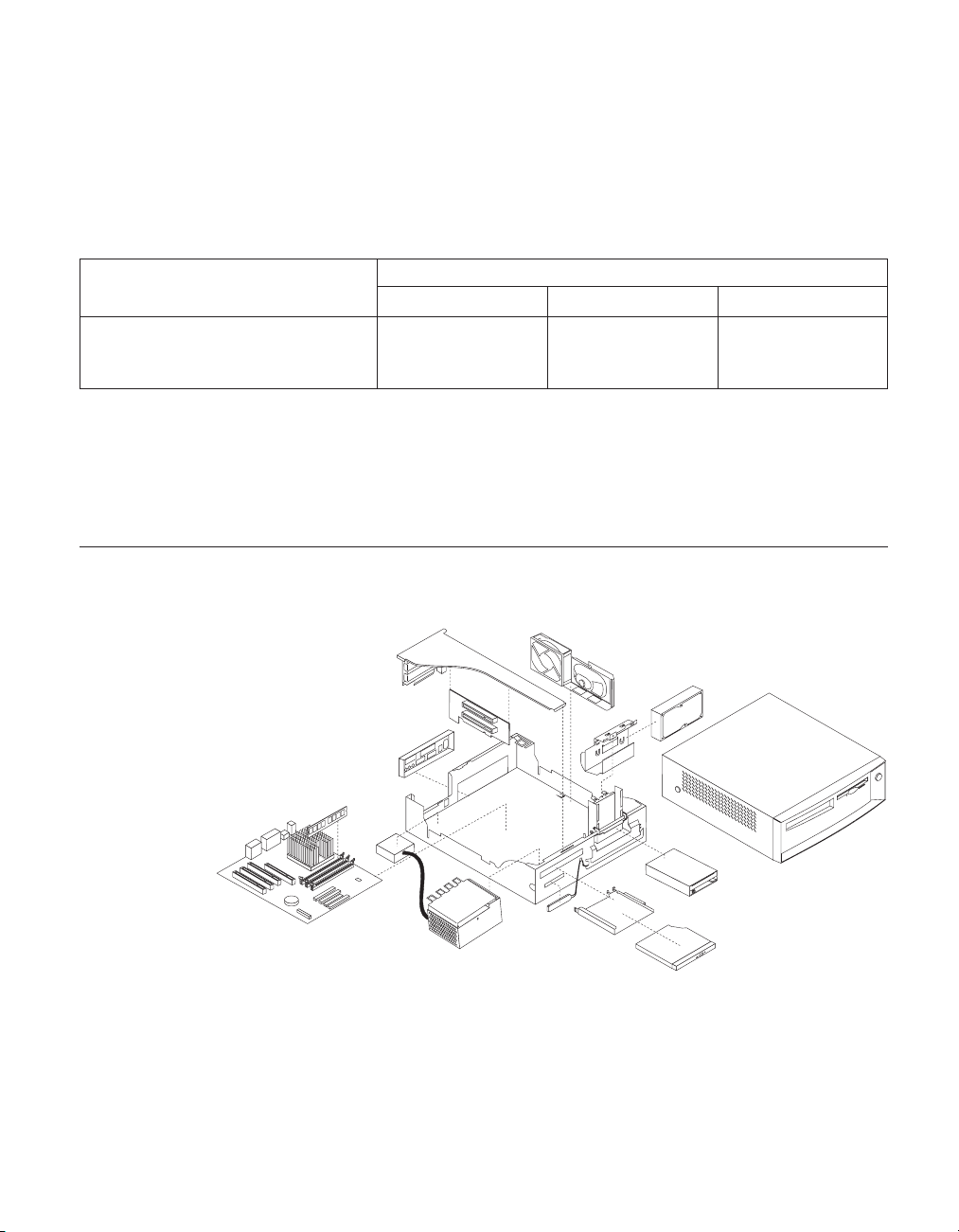
8. To exit from the Configuration/Setup Utility program, press Esc and
follow the instructions on the screen.
System board memory
The following matrix cross-references the name of the computer (printed on
the logo) and the size, speed, and type of memory modules supported in the
computer.
Computers Memory Module
Size Speed Type
Types6568/6569/6648/6649 64 MB128 MB256
MB
133 MHz SDRAMNon-
Supported memory configuration
DIMM sizes of 64 MB, 128 MB and 256 MB are acceptable. Start filling DIMM
socket 0, then 1. Use 3.3 V unbuffered 133 MHz SDRAM non-parity DIMMs
only.
Computer exploded view Types 6568/6569/6648/6649
ParityIndustry
Standard
Chapter 2. Types 6568/6569/6648/6649 55
Page 70
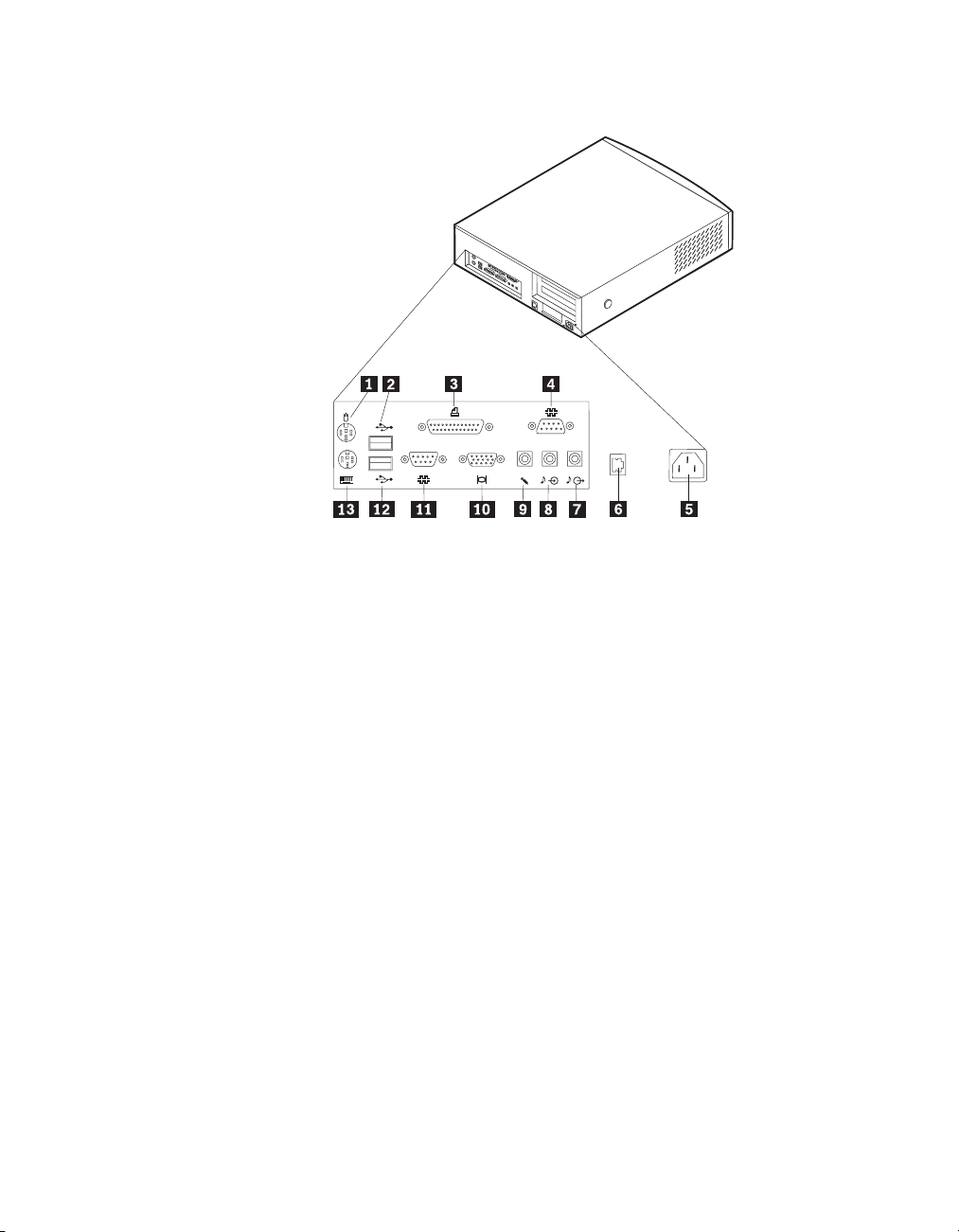
Input/Output connectors
2
1
1Mouse 8Audio input connector
2USB connector 2 9Microphone connector
3Parallel connector 10Monitor connector
4Serial connector 2 (joystick/MIDI connector in
some models)
5Power connector 12USB connector 1
6Ethernet connector 13Keyboard connector
7Audio output connector
11Serial connector 1
56 Hardware Maintenance Manual: IBM NetVista Computer Types 6058, 6059, 6269, 6568, 6569, 6578, 6579, 6648,
6649
Page 71
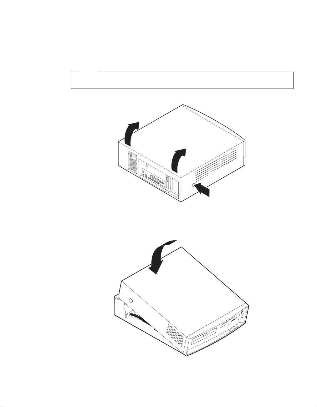
Cover removal
Firmly press the cover latch buttons on both sides. Pull up the back end of
cover, and swing the cover toward the front of the computer.
Note
The front panel is integrated with the top cover.
Replacing the cover
Position the cover over the chassis and pivot the cover down over the
computer until the cover snaps into place.
Chapter 2. Types 6568/6569/6648/6649 57
Page 72
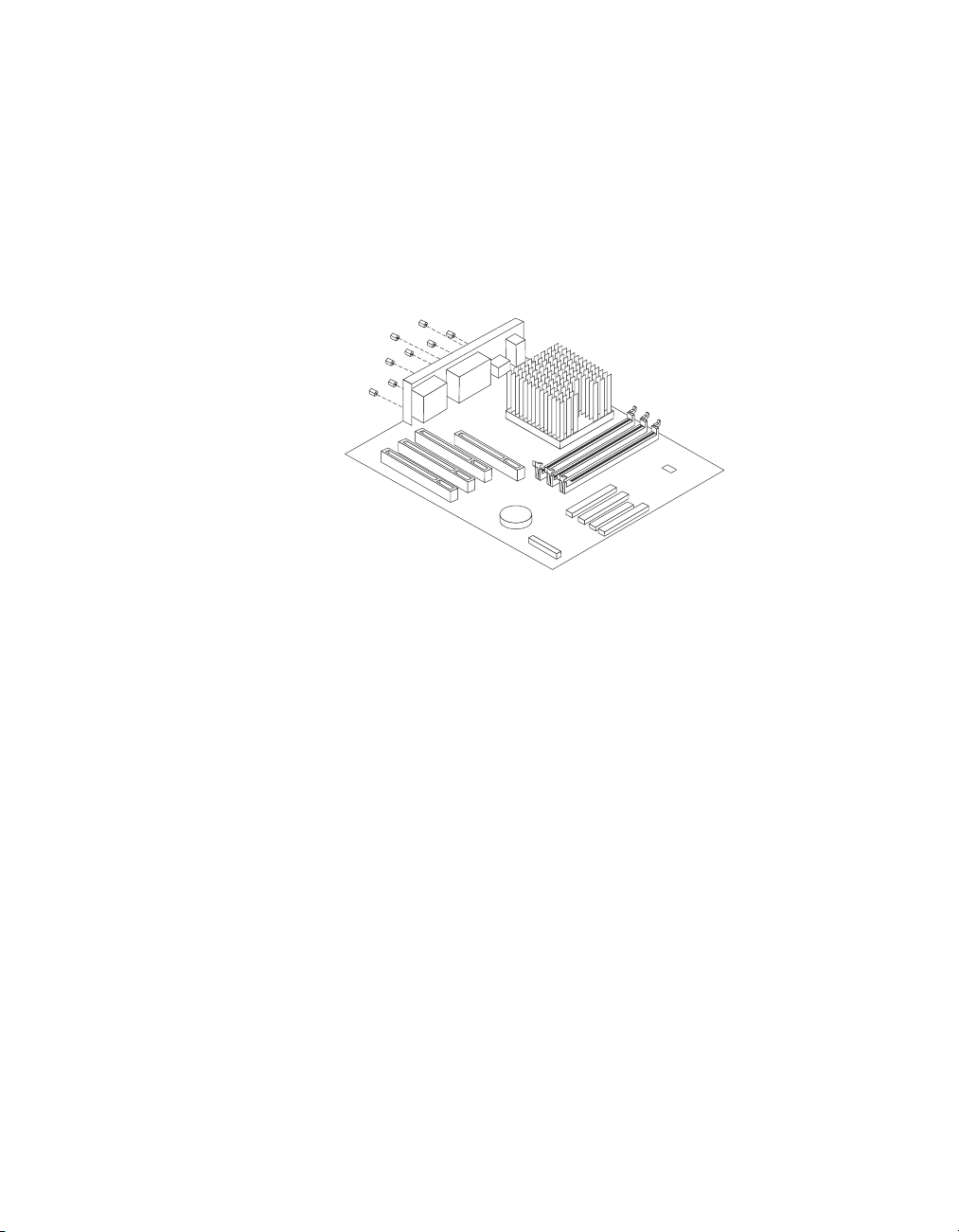
EMC shield (CD-ROM drive bay)
To remove the EMC shield:
1. Remove the front cover.
2. Remove the single screw that holds the EMC shield in place.
EMC shield (system board)
To remove the EMC shield from the system board:
1. Remove the eight I/O screws that hold the EMC shield in place.
58 Hardware Maintenance Manual: IBM NetVista Computer Types 6058, 6059, 6269, 6568, 6569, 6578, 6579, 6648,
6649
Page 73

Installing adapters
Adapter slots
To install an adapter in a PCI expansion slot:
1. Remove the riser card housing and place the housing on its side with the
adapter slots facing up.
2. Remove the adapter from its static-protective package.
3. Remove the screw and adapter slot cover for the adapter slot into which
you installing the adapter.
4. Install the adapter and insert the retaining screw.
Note: If you are installing a Wake on LAN supported network adapter,
attach the Wake on LAN cable that came with the adapter to the
Chapter 2. Types 6568/6569/6648/6649 59
Page 74

Wake on LAN connector on the system board. If you also want to
take advantage of the Alert on LAN feature of the computer, you
must install the network adapter in PCI slot 1. For the location of
PCI slot 1 and the Wake on LAN connector, see the diagram of the
system board on the inside of the computer.
5. Replace the riser card housing.
6. Replace the cover.
CD-ROM drive removal and replacement
1. Remove the riser card housing (see “Installing adapters” on page 59).
2. Remove the retaining lever and cable from the rear of the drive.
60 Hardware Maintenance Manual: IBM NetVista Computer Types 6058, 6059, 6269, 6568, 6569, 6578, 6579, 6648,
6649
Page 75
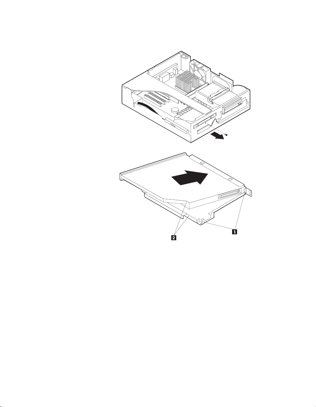
3. Remove the CD-ROM drive bracket retaining screw from the front of the
chassis and remove the CD-ROM drive bracket from the drive bay.
4. Install the slimline CD-ROM drive into the drive bay bracket, aligning the
tabs on the bay bracket 1 with the rear of the slimline CD-ROM drive
2and the tiny holes in the drive with the retaining pins in the drive bay
bracket.
5. Press the CD-ROM drive against the retaining spring in the bracket until
the drive is squarely oriented in the bracket and release the drive. You
should hear a slight click as the drive is secured into the bracket.
Chapter 2. Types 6568/6569/6648/6649 61
Page 76

6. Insert the CD-ROM drive and the bracket into the drive bay and replace
the screw.
7. Install the cable and replace the retaining lever behind the CD-ROM.
62 Hardware Maintenance Manual: IBM NetVista Computer Types 6058, 6059, 6269, 6568, 6569, 6578, 6579, 6648,
6649
Page 77

Internal drive removal
Note: The internal drive assembly is designed to latch firmly into place.
When pivoting the drive cage out, you will feel some initial resistance,
so you should pull firmly until the drive cage swings out. Inversely,
when you swing the cage back into the machine case, you should feel a
slight resistance until the cage snaps solidly back into place.
1. Pivot the drive bay cage up and toward the front of the computer.
2. Latch the handle to the front of the chassis, so that the drive cage stays
upright.
3.5″ drive removal
1. Remove the two screws from the right side of the drive. Lift the drive out.
Note: Be sure to place the 3.5″ drive cable under the single tab on the bottom
of the drive cage. Press the cable down so that the cable folds
underneath the drive cage, toward the front of the chassis, instead of
folding back toward the system board. This will ensure the 3.5″ drive
cable is not pinched when the drive cage is firmly placed into its
horizontal operating position.
Chapter 2. Types 6568/6569/6648/6649 63
Page 78

Hard drive removal
1. Latch the drive cage in the upright position.
2. Remove the 3.5″ drive cable from the tab at the bottom of the drive cage.
3. Remove the screw that holds the HD bracket, and lift the tabs that hold
the bracket in place. Lift the drive back and up.
4. Remove the HD cable from the drive and from the bottom of the drive
cage. Note the placement of the cable under the three tabs.
5. Remove the four screws on the side and bottom, and take the HD out of
the bracket.
Note: When replacing the HD in the drive cage, place the cable under the
three tabs at the bottom of the drive cage. Be sure to fold the 3.5″ drive
cable properly under the cage (see ″Note″ in “3.5″ drive removal” on
page 63).
Fan/speaker bracket removal
1. Locate the metal tab that secures the fan/speaker bracket to the chassis (on
the bottom of the bracket, just below the rear end of the speaker).
64 Hardware Maintenance Manual: IBM NetVista Computer Types 6058, 6059, 6269, 6568, 6569, 6578, 6579, 6648,
6649
Page 79

2. Press down on the tab, slide the bracket back and lift up.
Power supply removal
1. Remove the CD-ROM drive (see “CD-ROM drive removal and
replacement” on page 60).
2. Remove the two screws that secure the power supply to the front of the
chassis. Remove the two screws that secure the power cord plug to the
back of the chassis.
3. Locate the two tabs that secure the CD-ROM drive bracket to the back of
the power supply. Push in the two tabs and remove the bracket.
4. Lift out the power supply and plug.
Components of the riser card
The following illustration shows the location of PCI connectors on the riser
card. The Ethernet disable jumper pins (as seen in the diagram below) are
numbered as follows:
Chapter 2. Types 6568/6569/6648/6649 65
Page 80
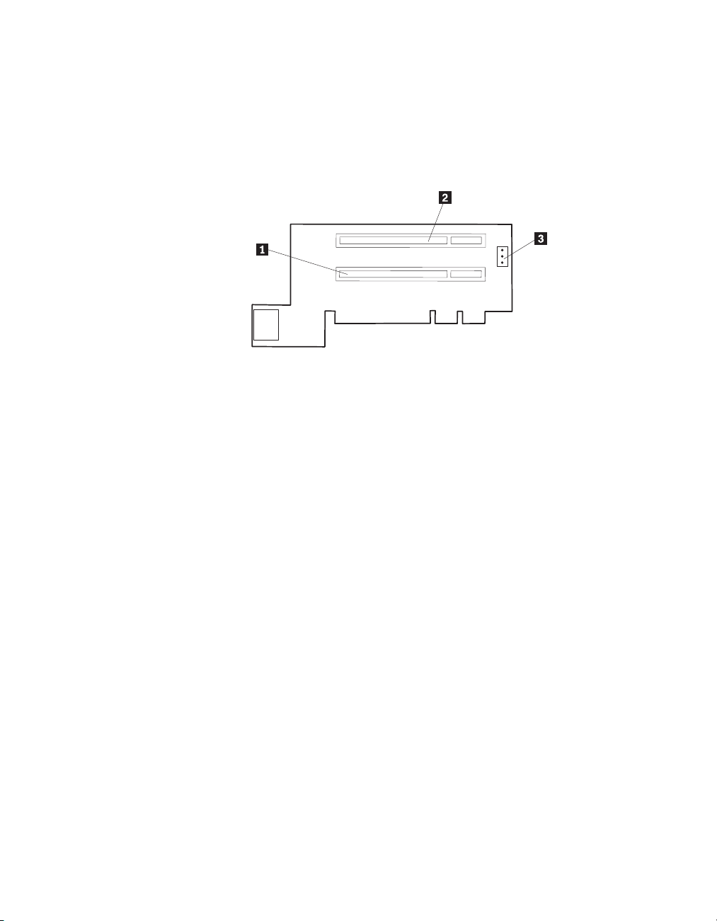
v Pin 1 is at the top.
v Pin 2 is in the middle.
v Pin 3 is at the bottom.
To enable Ethernet, jumper pins 1-2. To disable Ethernet, jumper pins 2-3.
1 PCI slot 1 3 Ethernet disable jumper
2 PCI slot 2
66 Hardware Maintenance Manual: IBM NetVista Computer Types 6058, 6059, 6269, 6568, 6569, 6578, 6579, 6648,
6649
Page 81
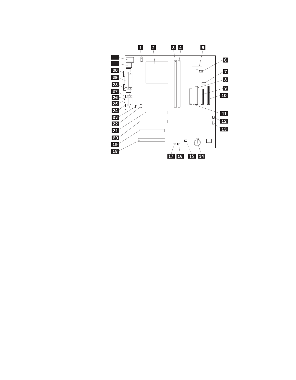
A40 and A40P system board layout
32
31
System board locations
1 #2 fan connector 17 Wake on LAN
2 Microprocessor 18 PCI slot 3
3 DIMM 0 19 PCI slot 2
4 DIMM 1 20 PCI slot 1
5 Power LED connector 21 AGP connector
6 RFID connector 22 CD-ROM audio
7 Front USB connector 23 Speaker connector
8 Secondary IDE connector 24 Audio output
9 Diskette connector 25 Audio input
10 Primary IDE connector 26 Serial port 2
11 Power connector 27 Microphone input
12 CMOS clear/recovery jumper 28 Monitor port
13 #1 fan connector 29 Parallel port
14 Battery 30 Serial port 1
15 SCSI adapter LED connector 31 USB connectors
16 Alert on LAN 32 Mouse and keyboard connectors
A40/A40P System board jumper settings
The following table contains the jumper setting information. (D) indicates the
default setting.
A40/A40P Clear CMOS/Flash Boot Block Recovery
Use the recovery jumper setting to Clear CMOS or to Flash Boot Block
Recover.
Chapter 2. Types 6568/6569/6648/6649 67
Page 82

Note: The A40/A40P CMOS clear/recovery jumper pins are numbered as
follows:
v Pin 1 is the farthest from the battery.
v Pins 2 and 3 are below pin 1, as seen in the A40/A40P System Board
layout.
Jumper Setting Description
CMOS Reset 2-3 CMOS Reset/Flash Recovery Mode
1-2 (D) Normal Mode
A40/ A40P Processor Speed Settings
Processor speed for type 6568/6569/6648/6649 computers are fixed and are
determined by the processor. There are no settings required.
A40/A40P Diskette Write Access
Diskette Write Enable and Write Protect options are changed in the Setup
Configuration. See “Setup Utility program” on page 41.
68 Hardware Maintenance Manual: IBM NetVista Computer Types 6058, 6059, 6269, 6568, 6569, 6578, 6579, 6648,
6649
Page 83

Symptom-to-FRU index
The Symptom-to-FRU index lists error symptoms and possible causes. The
most likely cause is listed first. Always begin with “General checkout” on
page 26. See “Chapter 1. IBM PC Enhanced Diagnostics error codes” on page 1
when running diagnostics. This index can also be used to help you decide
which FRUs to have available when servicing a computer. If you are unable to
correct the problem using this index, go to “Undetermined problems” on
page 90.
Notes
v If you have both an error message and an incorrect audio response,
diagnose the error message first.
v If you cannot run the diagnostic tests or you get a diagnostic error
code when running a test, but did receive a POST error message,
diagnose the POST error message first.
v If you did not receive any error message, look for a description of
your error symptoms in the first part of this index.
v Check all power supply voltages before you replace the system board.
(See “Power supply” on page 30.)
v Check the hard disk drive jumper settings before you replace a hard
disk drive. (See “Hard disk drive jumper settings” on page 48.)
Important
1.
Some errors are indicated with a series of beep codes (see “Beep
symptoms” on page 70).
Type 6568/6569/6648/6649 computers default to come up quiet (no
beep and no memory count and checkpoint code display) when no
errors are detected by POST. To enable beep and memory count and
checkpoint code display when a successful POST occurs, do the
following:
a. Select Start Options in the Configuration/Setup Utility program
(see “Setup Utility program” on page 41).
b. Set Power-On Self-Test to Enhanced.
2. The processor is a separate FRU from the system board; the processor
is not included with the system board FRU.
Chapter 2. Types 6568/6569/6648/6649 69
Page 84

Beep symptoms
Beep symptoms are short tones or a series of short tones separated by pauses
(intervals without sound). See the following examples.
Beeps Description
1-2-X
4 Four continuous beeps
Use the following table to diagnose beep symptoms.
Beep Symptom FRU/Action
1-1-3CMOS read-write error
1-1-4ROM BIOS check error
1-2-XDMA error
1-3-X
1-4-4
1-4-XError detected in first 64 KB of RAM
2-1-1, 2-1-2
2-1-XFirst 64 KB of RAM failed
2-2-2
2-2-XFirst 64 KB of RAM failed
2-3-X
v One beep
v A pause (or break)
v Two beeps
v A pause (or break)
v Any number of breaks
1. Run Setup
2. System Board
1. System Board
1. System Board
1. Memory Module
2. System Board
1. Keyboard
2. System Board
1. Memory Module
2. System Board
1. Run Setup
2. System Board
1. Memory Module
2. System Board
1. Video Adapter (if installed)
2. System Board
1. Memory Module
2. System Board
1. Memory Module
2. System Board
70 Hardware Maintenance Manual: IBM NetVista Computer Types 6058, 6059, 6269, 6568, 6569, 6578, 6579, 6648,
6649
Page 85

Beep Symptom FRU/Action
2-4-X
1. Run Setup
2. Memory Module
3. System Board
3-1-XDMA register failed
3-2-4Keyboard controller failed
1. System Board
1. System Board
2. Keyboard
3-3-4Screen initialization failed
1. Video Adapter (if installed)
2. System Board
Display
3-4-1Screen retrace test detected an error
1. Video Adapter (if installed)
2. System Board
3. Display
3-4-2POST is searching for video ROM
1. Video Adapter (if installed)
2. System Board
4
1. Video Adapter (if installed)
2. System Board
All other beep code sequences
One long and one short beep during POST.Base
640 KB memory error or shadow RAM error
One long beep and two or three short beeps
during POST.(Video error)
Three short beeps during POST
1. System Board
1. Memory Module
2. System Board
1. Video Adapter (if installed)
2. System Board
1. See “System board memory” on page 55
2. System Board
Continuous beep
Repeating short beeps
1. System Board
1. Keyboard stuck key?
2. Keyboard Cable
3. System Board
Chapter 2. Types 6568/6569/6648/6649 71
Page 86
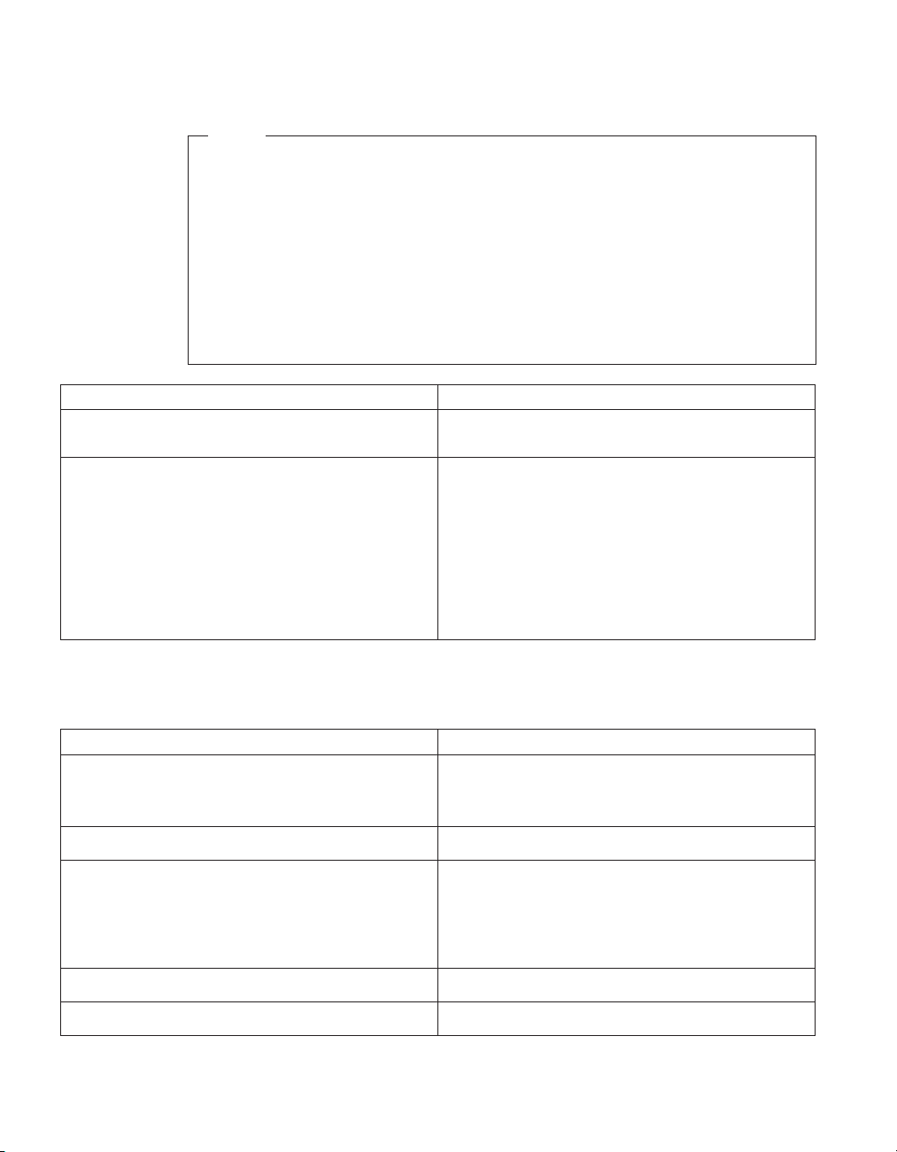
No-beep symptoms
Note
Type 6568/6569/6648/6649 computers default to come up quiet (no beep
and no memory count and checkpoint code display) when no errors are
detected by POST.
To enable beep and memory count and checkpoint code display when a
successful POST occurs, do the following:
1. Select Start Options in the Configuration/Setup Utility program (see
“Setup Utility program” on page 41).
2. Set Power-On Self Test to Enhanced.
Symptom/Error FRU/Action
No beep during POST but computer works
correctly.
No beep during POST.
1. System Board
1. See “Undetermined problems” on page 90
2. System Board
3. Memory Module
4. Any Adapter or Device
5. Riser Card
6. Power Cord
7. Power Supply
POST error codes
In the following index, X can represent any number.
POST Error Code FRU/Action
000SCSI Adapter not enabled
02X
08XCheck SCSI terminator installation.
101System board interrupt failure
102System board timer error
1. Verify adapter device and Bus Master fields
are enabled in PCI configuration program.
See documentation shipped with computer.
1. SCSI Adapter
1. SCSI Cable
2. SCSI Terminator
3. SCSI Device
4. SCSI Adapter
1. System Board
1. System Board
72 Hardware Maintenance Manual: IBM NetVista Computer Types 6058, 6059, 6269, 6568, 6569, 6578, 6579, 6648,
6649
Page 87

POST Error Code FRU/Action
106
110System board memory parity error
1. System Board
1. Memory Module
2. System Board
111I/O channel parity error
1. Reseat adapters
2. Any adapter
3. Riser card
4. System Board
114Adapter ROM error
1. Adapter Memory
2. System Board
3. Riser card
129Internal cache test error
1. Processor
2. L2 Cache Memory
3. System Board
151Real-time clock failure
161Bad CMOS battery
1. System Board
1. Run Setup
2. CMOS Backup Battery (see “Safety
information” on page 185)
3. System Board
162Configuration mismatch
1. Run Setup and verify Configuration
2. Had a device been added, removed, changed
location? If not, suspect that device.
3. Power-on external devices first, then power-on
computer
4. CMOS Backup Battery (see “Safety
information” on page 185)
System Board
5. System Board
6. Riser card
162And unable to run diagnostics
1. Diskette Drive
2. System Board
3. Diskette Drive Cable
4. Riser card
163Clock not updating or invalid time set
1. Time and Date Set?
2. CMOS Backup Battery (see “Safety
information” on page 185)
3. System Board
Chapter 2. Types 6568/6569/6648/6649 73
Page 88

POST Error Code FRU/Action
164POST detected a base memory or extended
memory size mismatch error or RIMM socket 3 is
populated with a RIMM memory module
166Boot Block Check Sum Error
167Microprocessor installed that is not supported
by the current POST/BIOS
168Alert on LAN error
17X, 18X
175
176
177Corrupted Administrator Password
178
183
184No RFID Antenna
185Corrupted boot sequence
186
187
1. Run Setup. Check System Summary menu for
memory size change. (See “Setup Utility
program” on page 41.)
2. Run the Extended Memory Diagnostic tests
1. Run Flash Recovery using Boot Block. See
“Flash recovery boot block jumper” on
page 50.
2. System Board
1. Run Setup. Check Stepping level for the
BIOS level needed, then perform the flash
update.
2. Processor
1. Run Setup. Check to see that Ethernet and
Alert on LAN are enabled.
2. System Board
3. Riser card
1. C2 Security
1. Run Configuration. See “Setup Utility
program” on page 41.
2. System Board
1. Covers were removed from the computer
1. System Board
1. System Board
1. Enter the administrator password
1. Make sure Asset Care and Asset ID are
enabled in Configuration/Setup
2. RFID Antenna
3. System Board
4. Riser card
1. Set configuration and reinstall the boot
sequence
1. System Board
1. Clear Administration password
2. System Board
74 Hardware Maintenance Manual: IBM NetVista Computer Types 6058, 6059, 6269, 6568, 6569, 6578, 6579, 6648,
6649
Page 89

POST Error Code FRU/Action
189
1. More than three password attempts were
made to access the computer
190Chassis intrusion detector was cleared. This is
information only, no action required. If this code
1. System Board
does not clear:
1XXNot listed above
201, 20XMemory data error
1. System Board
1. Run Enhanced Diagnostics Memory Test
2. Memory Module
3. System Board
225
229External cache test error
1. Unsupported Memory
1. L2 Cache Memory
2. System Board
262POST detected a base memory or extended
memory type error
1. Run Setup. Check System Summary menu for
memory. (See “Setup Utility program” on
page 41.)
2. Run the Extended Memory Diagnostic tests.
301
1. Keyboard
2. Keyboard Cable
3. System Board
303With an 8603 error
1. Mouse
2. Keyboard
3. Keyboard Cable
4. System Board
303With no 8603 error
1. Keyboard
2. Keyboard Cable
3. System Board
3XXNot listed above
1. Keyboard
2. Keyboard Cable
3. System Board
5XX
1. Video Adapter (if installed)
2. System Board
601
1. Diskette Drive A
2. Diskette Drive Cable
3. System Board
4. Riser card
Chapter 2. Types 6568/6569/6648/6649 75
Page 90

POST Error Code FRU/Action
602
1. Bad Diskette?
2. Verify Diskette and retry
604And able to run diagnostics
1. Run Setup and verify diskette configuration
settings
2. Diskette Drive A/B
3. Diskette Drive Cable
4. System Board
5. Riser card
605POST cannot unlock the diskette drive
1. Diskette Drive
2. Diskette Drive Cable
3. System Board
4. Riser card
662
1. Diskette drive configuration error or wrong
diskette drive type; run Setup Configuration
6XXNot listed above
1. Diskette Drive
2. System Board
3. Riser card
4. External Drive Adapter
5. Diskette Drive Cable
6. Power Supply
762Math coprocessor configuration error
1. Run Setup
2. Processor
3. System Board
7XX Not listed above
1. Processor
2. System Board
962 Parallel port configuration error
1. Run Configuration
2. Parallel Adapter (if installed)
3. System Board
9XX
1. Printer
2. System Board
1047
1. 16-Bit AT
™
Fast SCSI Adapter
76 Hardware Maintenance Manual: IBM NetVista Computer Types 6058, 6059, 6269, 6568, 6569, 6578, 6579, 6648,
6649
Page 91

POST Error Code FRU/Action
107XCheck SCSI terminator installation
1. Check SCSI terminator installation
2. SCSI Cable
3. SCSI Terminator
4. SCSI Device
5. SCSI Adapter
1101Serial connector error, possible system board
failure
1101, 1102, 1106, 1108, 1109
1. Run Enhanced Diagnostics
1. System Board
2. Any Serial Device
1107
1. Communications Cable
2. System Board
1102Card selected feedback error
1103Port fails register check
1. Run Enhanced Diagnostics
1. Run Enhanced Diagnostics
2. System Board
1106Serial option cannot be turned off
1. Run Enhanced Diagnostics
2. System Board
1107
1. Serial Device Cable
2. System Board
1110Register test failed
1. Run Enhanced Diagnostics
2. System Board
1116Interrupt error
1117Failed baud rate test
1162 Serial port configuration error
1. Run Enhanced Diagnostics
1. Run Enhanced Diagnostics
1. Run Configuration
2. Serial Adapter
(if installed)
3. System Board
11XXNot listed above
1201
1. System Board
1. System Board
2. Any Serial Device
1202, 1206, 1208, 1209, 12XX
1. Dual Async Adapter/A
2. System Board
3. Any Serial Device
Chapter 2. Types 6568/6569/6648/6649 77
Page 92

POST Error Code FRU/Action
1207
13XX
1402Printer not ready Information only
1403No paper error, or interrupt failure Information only
1404System board timeout failure
1405Parallel adapter error
1406Presence test error
14XXNot listed above. Check printer before
replacing system board
15XX
1692Boot sequence error
16XX
1762Hard disk drive configuration error
1780 (Disk Drive 0)1781 (Disk Drive 1)1782 (Disk
Drive 2)1783 (Disk Drive 3)
180X, 188XPCI configuration or resource error
1962Boot sequence error
209X
1. Communications Cable
2. Dual Async Adapter/A
1. Game Adapter
1. Run Enhanced Diagnostics
1. Run Enhanced Diagnostics
1. Run Enhanced Diagnostics
1. Printer
2. System Board
1. SDLC Adapter
1. Run FDISK to ensure at least one active
partition is set active
1. 36/38 Workstation Adapter
1. Run Configuration (See “Setup Utility
program” on page 41)
1. See “Power supply” on page 30
2. Hard Disk Drive
3. System Board
4. Riser card
5. Hard Disk Cable
6. Power Supply
1. Run Setup and verify PCI/ISA configuration
settings.
2. If necessary, set ISA adapters to Not available to
allow PCI adapters to properly configure.
3. Remove any suspect ISA adapters.
4. Rerun diagnostics.
5. PCI Adapter
1. Possible hard disk drive problem; see “Hard
disk drive boot error” on page 42
1. Diskette Drive
2. Diskette Cable
78 Hardware Maintenance Manual: IBM NetVista Computer Types 6058, 6059, 6269, 6568, 6569, 6578, 6579, 6648,
6649
Page 93

POST Error Code FRU/Action
20XXNot listed above
21XX
1. BSC Adapter
1. SCSI Device
2. 16-bit AT Fast SCSU adapter
3. Alternate BSC adapter
2401, 2402If screen colors change
2401, 2402If screen colors are OK
1. Display
1. System Board
2. Display
2409
2410
1. Display
1. System Board
2. Display
2462Video memory configuration error
1. Check cable connections
2. Run Setup and verify video configuration
settings
3. Video Memory Modules
4. Video Adapter (if installed)
5. System Board
4611, 4630
1. Multiport/2 Interface Board
2. Multiport/2 Adapter
4612, 4613, 4640, 4641
1. Memory Module Package
2. Multiport/2 Adapter
4650
46XXNot listed above
1. Multiport/2 Interface Cable
1. Multiport/2 Adapter
2. Multiport/2 Interface
Board
3. Memory Module
5600
5962An IDE device (other than hard drive)
configuration error
1. Financial System Controller Adapter
1. Run Configuration
2. CD-ROM Drive
3. CD-ROM Adapter
4. Zip or other ATAPI device
5. System Board
6. Riser card
Chapter 2. Types 6568/6569/6648/6649 79
Page 94

POST Error Code FRU/Action
62XX
63XX
64XX
71XX
74XX
76XX
78XX
79XX
80XX
84XX
8601, 8602
8603, 8604
86XXNot listed above
89XX
91XX
96XX
10101, 10102, 10104, 10105, 10106, 10107, 10108,
10109, 10111,
10112, 10113, 10114,
10115, 10116
1. 1st Store Loop Adapter
2. Adapter Cable
1. 2nd Store Loop Adapter
2. Adapter Cable
1. Network Adapter
1. Voice Adapter
1. Video Adapter
(if installed)
1. Page Printer Adapter
1. High Speed Adapter
1. 3117 Adapter
1. PCMCIA Adapter
1. Speech Adapter
2. Speech Control Assy.
1. Pointing Device (Mouse)
2. System Board
1. System Board
2. Pointing Device
(Mouse)
1. Mouse
2. System Board
1. PC Music Adapter
2. MIDI Adapter Unit
1. Optical Drive
2. Adapter
1. SCSI Adapter
2. Any SCSI Device
3. System Board
4. Riser card
1. Have customer verify correct operating system
device drivers are installed and operational.
2. Modem
80 Hardware Maintenance Manual: IBM NetVista Computer Types 6058, 6059, 6269, 6568, 6569, 6578, 6579, 6648,
6649
Page 95

POST Error Code FRU/Action
10103, 10110, 101171
1. System Board
2. Data/Fax Modem
3. Riser card
10117Not listed above
1. Check system speaker
2. Check PSTN cable
3. External DAA
(if installed)
4. Modem
10118
1. Run Diagnostics and verify the correct
operation of the modem slot
2. Modem
10119
1. Diagnostics detected a non-IBM modem
2. Modem
10120
1. Check PSTN Cable
2. External DAA
(if installed)
3. Modem
10132, 10133, 10134,
10135, 10136, 10137,
1. Modem
10138, 10139, 10140,
10141, 10142, 10143,
10144, 10145, 10146,
10147, 10148, 10149,
10150, 10151, 10152
10153
1. Data/Fax Modem
2. System Board
3. Riser card
101XXNot listed above
1. Modem Adapter/A
2. Data/Fax Modem
3. System Board
4. Riser card
10450, 10451, 10490,
10491, 10492, 10499Read/write error
1. Run Enhanced Diagnostics
2. Hard Disk Drive
3. System Board
4. Riser card
10452Seek test error
1. Run Enhanced Diagnostics
Chapter 2. Types 6568/6569/6648/6649 81
Page 96

POST Error Code FRU/Action
10453Wrong drive type? Information only
10454Sector buffer test error
10455, 10456Controller error
10459Drive diagnostic command error Information only
10461Drive format error
10462Controller seek error
10464Hard Drive read error
10467Drive non-fatal seek error
10468Drive fatal seek error
10469Drive soft error count exceeded
10470, 10471, 10472Controller wrap error
10473Corrupt data. Low level format might be
required
10480
10481ESDI drive D seek error
10482Drive select acknowledgement bad
106X1
10635
10651, 10660
106XXNot listed above
107XX
1. Run Enhanced Diagnostics
1. Run Enhanced Diagnostics
1. Run Enhanced Diagnostics
1. Run Enhanced Diagnostics
1. Run Enhanced Diagnostics
1. Run Enhanced Diagnostics
1. Run Enhanced Diagnostics
1. Run Enhanced Diagnostics
1. Run Enhanced Diagnostics
Information only
1. Hard Disk Drive (ESDI)
2. Drive Cable
3. System Board
1. Run Enhanced Diagnostics
1. Run Enhanced Diagnostics
1. Check Configuration
2. Ethernet Adapter
1. Power-off computer, wait ten seconds then
power-on the computer
2. Ethernet Adapter
1. Check Cables
2. Ethernet Adapter
1. Ethernet Adapter
1. 5.25-inch External
Diskette Drive
2. 5.25-inch Diskette
Drive Adapter/A
82 Hardware Maintenance Manual: IBM NetVista Computer Types 6058, 6059, 6269, 6568, 6569, 6578, 6579, 6648,
6649
Page 97

POST Error Code FRU/Action
109XXCheck the adapter cables
1. ActionMedia
Adapter/A
2. System Board
3. Riser card
112XXThis adapter does not have cache
1. SCSI Adapter
2. Any SCSI Device
3. System Board
4. Riser card
119XX
121XX
1. 3119 Adapter
1. Modem Adapter
2. Any Serial Device
3. System Board
4. Riser card
136XX
1. ISDN Primary Rate Adapter
2. System Board
3. Riser card
137XX
141XX
1. System Board
1. Realtime Interface Coprocessor Portmaster
Adapter/A
143XX
1. Japanese Display Adapter
2. System Board
3. Riser card
14710, 14711
1. System Board Video Adapter
2. Adapter Video Memory
148XX
14901, 14902,
1491X, 14922
1. Video Adapter
1. Video Adapter
(if installed)
2. System Board
3. Riser card
4. Display (any type)
14932
1. External Display
2. Video Adapter
161XX
1. FaxConcentrator Adapter
Chapter 2. Types 6568/6569/6648/6649 83
Page 98

POST Error Code FRU/Action
164XX
16500
16520, 16540
166XX, 167XX
18001 to 18029
18031 to 18039
185XXXX
20001 to 20003
20004
20005 to 20010
200XXNot listed above
20101 to 20103
1. 120 MB Internal Tape Drive
2. Diskette Cable
3. System Board
4. Riser card
1. 6157 Tape Attachment
2. Adapter
1. 6157 Streaming Tape Drive
2. 6157 Tape Attachment Adapter
1. Token Ring Adapter
2. System Board
3. Riser card
1. Wizard Adapter
2. Wizard Adapter Memory
1. Wizard Adapter Cable
1. DBCS Japanese Display Adapter/A
2. System Board
3. Riser card
1. Image Adapter/A
Image-I Adapter/A
2. Memory Module DRAM, VRAM
1. Memory Module DRAM, VRAM
2. Image Adapter/A
Image-I Adapter/A
1. Image Adapter/A
Image-I Adapter/A
2. Memory Module DRAM, VRAM
1. Image Adapter/A
2. Image-I Adapter/A
3. Memory Module DRAM, VRAM
4. System Board
5. Riser card
1. Printer/Scanner Option
2. Image Adapter/A
3. Memory Module DRAM, VRAM
84 Hardware Maintenance Manual: IBM NetVista Computer Types 6058, 6059, 6269, 6568, 6569, 6578, 6579, 6648,
6649
Page 99

POST Error Code FRU/Action
20104
1. Memory Module DRAM, VRAM
2. Printer/Scanner Option
3. Image Adapter/A
20105 to 20110
1. Printer/Scanner Option
2. Image Adapter/A
3. Memory Module DRAM, VRAM
Image Adapter/A Memory Test failure indicated
by graphic of adapter
206XX
1. Replace memory module (shown in graphic)
1. SCSI-2 Adapter
2. Any SCSI Device
3. System Board
4. Riser card
208XXVerify there are no duplicate SCSI ID
settings on the same bus.
210XXXXInternal bus, size
unknown210XXX1External bus, size unknown
1. Any SCSI Device
1. SCSI Hard Disk Drive
2. SCSI Adapter or System Board
3. SCSI Cable
4. SCSI ID Switch (on some models)
Tape Drive amber LED remains on
1. Tape Drive
2. SCSI Cable (internal)
3. SCSI Adapter or System Board
Tape Drive green ″in use″ LED fails to come on
1. Tape Drive
2. SCSI Adapter or System Board
3. SCSI Cable (internal)
4. SCSI Cable (external)
Tape automatically ejected from drive
1. Tape Cassette
Drive
SCSI ID on rotary switch does not match SCSI ID
set in configuration. Verify drive switches inside
cover are set to zero
1. Rotary Switch Circuit Board
2. Circuit Board Cable
3. Tape Drive
Tape sticks or breaks in drive. Verify that the tapes
used meet ANSI standard X3B5
212XX
1. Tape Cassette
1. SCSI Printer
2. Printer Cable
213XX
1. SCSI Processor
Chapter 2. Types 6568/6569/6648/6649 85
Page 100

POST Error Code FRU/Action
214XX
215XXXC, 215XXXD, 215XXXE, 215XXXUIf an
external device, and power-on LED is off, check
external voltages
216XX
217XXIf an external device, and power-on LED is
off, check external voltages
218XXCheck for multi CD tray or jukebox
219XX
24201Y0, 24210Y0Be sure wrap plug is attached
273XX
27501, 27503, 27506, 27507
27502, 27504, 27510, 27511, 27533, 27534, 27536,
27537
27509
27512
27535
27554
27555, 27556
1. WORM Drive
1. CD-ROM Drive I
2. CD-ROM Drive II
Enhanced CD-ROM Drive II
Any CD-ROM Drive
3. SCSI Cable
4. SCSI Adapter or System Board
1. Scanner
1. Rewritable Optical Drive
2. SCSI Adapter or System Board
3. SCSI Cable
1. Changer
1. SCSI Communications Device
1. ISDN/2 Adapter
2. ISDN/2 Wrap Plug
3. ISDN/2 Communications Cable
1. 1 Mbps Micro Channel
2. Infrared LAN Adapter
1. ServerGuard Adapter
2. System Board
3. Riser card
1. ServerGuard Adapter
1. Remove redundant adapters, run Auto
Configuration program, then retest.
1. WMSELF.DGS diagnostics file is missing
2. WMSELF.DGS diagnostics file is incorrect
1. 3V Lithium Backup Battery
2. ServerGuard Adapter
1. Internal Temperature out of range
2. ServerGuard Adapter
1. ServerGuard Adapter
2. Power Supply
86 Hardware Maintenance Manual: IBM NetVista Computer Types 6058, 6059, 6269, 6568, 6569, 6578, 6579, 6648,
6649
 Loading...