

Page 1

IBM Personal Computer Ty pe s 2179 and 6643
Hardw are Maintenance Manual
Page 2

Page 3

IBM Personal Computer Ty pe s 2179 and 6643
Hardw are Maintenance Manual
Page 4

to
©
US
:
Note: Before using this information and the product it supports, be sure to read the general information under “Notices” on page
116.
Third Edition (July 2004)
INTERNATIONAL BUSINESS MACHINES CORPORATION PROVIDES THIS PUBLICATION “AS IS” WITHOUT
WARRANTY OF ANY KIND, EITHER EXPRESS OR IMPLIED, INCLUDING, BUT NOT LIMITED TO, THE
IMPLIED WARRANTIES OF MERCHANTABILITY OR FITNESS FOR A PARTICULAR PURPOSE. Some states do
not allow disclaimer of express or implied warranties in certain transactions, therefore, this statement may not
apply to you.
This publication could include technical inaccuracies or typographical errors. Changes are periodically made to the
information herein; these changes will be incorporated in new editions of the publication. IBM may make
improvements and/or changes in the product(s) and/or the program(s) described in this publication at any time.
This publication was developed for products and services offered in the United States of America. IBM may not
offer the products, services, or features discussed in this document in other countries, and the information is subject
change without notice. Consult your local IBM representative for information on the products, services, and
features available in your area.
Requests for technical information about IBM products should be made to your IBM reseller or IBM marketing
representative.
Copyright International Business Machines Corporation 2004. All rights reserved.
Government Users Restricted Rights – Use, duplication or disclosure restricted by GSA ADP Schedule Contract
with IBM Corp.
Page 5
v
a
v
Be
©
About this manual
Important safety information . . . . . . . . iii
This manual contains service and reference information for the IBM Personal
Computer, Types 2179 and 6643.
This manual is divided into product service sections, by type, and a related service
section as follows:
The product service sections include procedures for isolating problems to a FRU,
Symptom-to-FRU Index, additional service information, and an illustrated
parts catalog.
The related service section includes safety notices and safety information, and
problem determination tips.
Attention:
This manual is intended for trained servicers who are familiar with IBM Personal
Computer products. Use this manual along with advanced diagnostic tests to
troubleshoot problems effectively.
Before servicing an IBM product, be sure to review the “Safety notices
(multi-lingual translations)” on page 77 and “Safety information” on page 102.
Important safety information
sure to read all caution and danger statements in this book before performing
any of the instructions.
Online support . . . . . . . . . . . .iv
Leia todas as instruções de cuidado e perigo antes de executar qualquer operação.
Copyright IBM Corp. 2004
iii
Page 6
iv
Prenez connaissance de toutes les consignes de type Attention et
Danger avant de procéder aux opérations décrites par les instructions.
Lesen Sie alle Sicherheitshinweise, bevor Sie eine Anweisung ausführen.
Accertarsi di leggere tutti gli avvisi di attenzione e di pericolo prima di effettuare
qualsiasi operazione.
Lea atentamente todas las declaraciones de precaución y peligro ante de llevar a
cabo cualquier operación.
Online support
Use the World Wide Web (WWW) to download Diagnostic, BIOS Flash, and Device
Driver files, and Documents.
The Web address is:
http://www.ibm.com/support
Hardware Maintenance Manual
Page 7

©
Contents
About this manual . . . . . . . . . . iii
Important safety information . . . . . . . . iii
Online support . . . . . . . . . . . .iv
Chapter 1. General checkout . . . . . .1
General Checkout . . . . . . . . . . . . .1
Module test menu and hardware configuration
report . . . . . . . . . . . . . . . .2
Chapter 2. General information . . . . .3
Features . . . . . . . . . . . . . . . .3
Security . . . . . . . . . . . . . . .3
Specifications . . . . . . . . . . . . . .3
Chapter 3. Diagnostics . . . . . . . .5
Setup Utility program . . . . . . . . . . .5
Diagnostics and test information . . . . . . .5
IBM PC Enhanced Diagnostics . . . . . . . .6
Diagnostics program download . . . . . . .6
Starting the IBM PC Enhanced Diagnostics
Program . . . . . . . . . . . . . . .6
Navigating through the diagnostics programs . .7
Running diagnostics tests . . . . . . . . .7
Test selection . . . . . . . . . . . . .7
IBM PC Enhanced Memory Diagnostics . . . .7
Alert-On LAN test . . . . . . . . . . .8
Asset ID test . . . . . . . . . . . . .8
Test results . . . . . . . . . . . . . .8
Hard file Smart test . . . . . . . . . . .9
Fixed Disk Optimized Test . . . . . . . . .9
Quick and Full erase - hard drive . . . . . .9
Iomega Zip drive test . . . . . . . . . .10
Asset EEPROM backup . . . . . . . . .10
Viewing the test log . . . . . . . . . .10
Hard disk drive boot error . . . . . . . .11
When to use the Low-Level Format program . .12
Preparing the hard disk drive for use . . . . .12
Chapter 4. FRU replacements . . . . .13
Moving The Computer . . . . . . . . . .13
System board layout . . . . . . . . . . .14
CMOS Clear jumper settings . . . . . . . .15
Processor Speed Settings . . . . . . . . . .15
System Board Memory . . . . . . . . . .15
Removing a DIMM . . . . . . . . . . . .15
Installing a DIMM . . . . . . . . . . . .16
Power Supply . . . . . . . . . . . . .16
20-pin main power supply connection . . . . .16
Display . . . . . . . . . . . . . . . .17
Computer exploded view (Types 2179 and 6643) . .18
Input/Output connectors . . . . . . . . . .19
Controls and status indicators . . . . . . . .20
Rear bucket housing (rear cover) removal . . . .21
Upper base cover and base cover wing removal . .22
Hard disk drive removal . . . . . . . . . .23
Rear EMC cover assembly removal . . . . . .23
Diskette drive/CD-ROM drive/DVD drive removal 24
Removing the drives from the drive bracket
assembly . . . . . . . . . . . . . .24
Speaker assembly removal . . . . . . . . .25
Battery removal and installation . . . . . . .25
Fan removal . . . . . . . . . . . . . .26
Power supply removal . . . . . . . . . . .26
Processor removal . . . . . . . . . . . .28
System board removal . . . . . . . . . . .29
Power inverter board removal . . . . . . . .29
Chassis assembly removal . . . . . . . . .31
Front bezel removal . . . . . . . . . . .32
LCD removal . . . . . . . . . . . . . .32
LCD Receiver card removal . . . . . . . . .33
Installing the Receiver card . . . . . . . .34
Hinge assembly removal . . . . . . . . . .34
Chapter 5. Symptom-to-FRU Index . . .35
Beep symptoms . . . . . . . . . . . . .35
Hard disk drive boot error . . . . . . . . .36
IBM Enhanced Diagnostic error codes . . . . .37
POST error codes . . . . . . . . . . . .54
Undetermined problems . . . . . . . . . .56
Chapter 6. Parts listing . . . . . . . .57
System Type 2179 . . . . . . . . . . . .57
System Type 6643 . . . . . . . . . . . .61
Keyboards . . . . . . . . . . . . . . .64
Keyboards . . . . . . . . . . . . . . .65
Computer power cords . . . . . . . . . .66
Chapter 7. Additional service
information . . . . . . . . . . . . .69
Security . . . . . . . . . . . . . . .69
Passwords . . . . . . . . . . . . . .69
Power-on password . . . . . . . . .69
Removing a power-on password . . . .69
Administrator password . . . . . . . .70
Administrator password control . . . . .70
Operating system password . . . . . . .70
Vital product data . . . . . . . . . . .70
Alert on LAN . . . . . . . . . . . .70
Hard disk drive jumper settings . . . . . .70
IDE hard disk drive settings . . . . . . .71
CD-ROM drive/DVD drive jumper settings . .71
BIOS levels . . . . . . . . . . . . .71
CMOS Clear Procedure . . . . . . . . .72
Flash (BIOS/VPD) update procedure . . . . .72
Power management . . . . . . . . . .73
Advanced Configuration and Power Interface
(ACPI) BIOS . . . . . . . . . . . . . .73
Advanced Power Management . . . . . . . .73
Automatic Hardware Power Management features 73
Copyright IBM Corp. 2004
v
Page 8

vi
Setting Automatic Hardware Power Management
features . . . . . . . . . . . . . . . .73
Automatic Power-On features . . . . . . . .74
Network settings . . . . . . . . . . . .74
Flash over LAN (update POST/BIOS over network) 74
Wake on LAN . . . . . . . . . . . . .75
Chapter 8. Related service information 77
Safety notices (multi-lingual translations) . . . .77
Safety information . . . . . . . . . . . . 102
General safety . . . . . . . . . . . . 102
Grounding requirements . . . . . . . . 102
Electrical safety . . . . . . . . . . . . 102
Handling electrostatic discharge-sensitive
devices . . . . . . . . . . . . . . 104
Safety inspection guide . . . . . . . . . 104
Problem determination tips . . . . . . . . . 106
File updates . . . . . . . . . . . . . 106
Adding adapters to the system . . . . . . 106
Software considerations . . . . . . . . . 107
BIOS . . . . . . . . . . . . . . 107
Drivers . . . . . . . . . . . . . 107
Hardware considerations . . . . . . . . 108
System resource conflicts . . . . . . . . 109
Miscellaneous information . . . . . . . . . 111
Acronyms, Abbreviations, and Terms . . . . 111
Send Us Your Comments! . . . . . . . . .114
Notices . . . . . . . . . . . . . . .116
Trademarks . . . . . . . . . . . . . .117
Hardware Maintenance Manual
Page 9

or
to
1.
2.
3. If
4. If
5. If
6. If
7. If an
1.
2.
3.
4.
CD
5.
6.
7.
a.
b.
©
Chapter 1. General checkout
General Checkout
This general checkout procedure is for types 2179 and 6643 computers.
Attention:
The drives in the computer you are servicing might have been rearranged or the drive startup sequence changed. Be
extremely careful during write operations such as copying, saving or formatting. Data or programs can be
overwritten if you select an incorrect drive.
Diagnostic error messages appear when a test program finds a problem with a
hardware option. For the test programs to properly determine if a test Passed, Failed
Aborted, the test programs check the error-return code at test completion. See
“IBM PC Enhanced Diagnostics” on page 6.
General error messages appear if a problem or conflict is found by an application
program, the operating system, or both. For an explanation of these messages, refer
the information supplied with that software package.
Notes:
Use Beep codes and the IBM Enhanced Diagnostics to diagnose and fix problems.
Types 2179 and 6643 computers default to come up quiet (no beep and no memory count and checkpoint code
display) when no errors are detected.
Before replacing any FRUs, ensure that the latest level of BIOS is installed on the system. A down-level BIOS
might cause false errors and unnecessary replacement of the system board. For more information on how to
determine and obtain the latest level BIOS, see “BIOS levels” on page 71.
there is a Beep code, go to “Beep symptoms” on page 35.
multiple error codes are displayed, diagnose the first error code displayed.
the computer hangs with a POST error, go to “POST error codes” on page 54.
the computer hangs and no error is displayed, go to “Undetermined problems” on page 56.
installed device is not recognized by the diagnostics program, that device might be defective.
001
Power-off the computer and all external devices.
Check all cables and power cords.
Set all display controls to the middle position.
Insert the IBM Enhanced Diagnostics diskette into drive A or the CD into the
drive.
Power-on all external devices.
Power-on the computer.
Check for the following response:
One or two beeps (depending on the diagnostics version level).
Readable instructions or the Main Menu.
Copyright IBM Corp. 2004
YOU RECEIVE THE CORRECT RESPONSE?
DID
1
Page 10

If
If
1.
2.
3.
4. Be
5.
6.
OR 7. Go to
v If
go to
v If
v If
1. At
2. At
If an
v
v
v An
v A
v
v
If a
2
If NO, continue to 002.
YES, proceed to 003.
002
the Power Management feature is enabled, do the following:
Start the Configuration/Setup Utility program (see “Setup Utility program” on
page 5.)
Select Power Management from the Configuration/Setup Utility program
menu.
Select APM.
sure APM BIOS Mode is set to Disabled. If it is not, press Left Arrow (}) or
Right Arrow (Æ) to change the setting.
Select Automatic Hardware Power Management.
Set Automatic Hardware Power Management to Disabled.
“IBM PC Enhanced Diagnostics” on page 6.
003
Run the IBM PC Enhanced Diagnostics test. If necessary, refer to “Diagnostics and
test information” on page 5.
you receive an error, replace the part that the diagnostic program calls out or
“IBM PC Enhanced Diagnostics” on page 6.
the test stops and you cannot continue, replace the last device tested.
the LCD display has problems such as black screen, blinking on-off, or the
screen pallet color is wrong, go to “Display” on page 17.
Module test menu and hardware configuration report
Depending on the diagnostics version level you are using, the installed devices in
the computer are verified in one of two ways:
the start of the diagnostic tests, the Module Test Menu is displayed.
Normally, all installed devices in the computer are highlighted on the menu.
the start of the diagnostic tests, the main menu appears. From this menu,
select System Info then select Hardware Configuration from the next menu.
Normally, all installed devices in the computer are highlighted on this report.
installed device is not recognized by the diagnostics program:
The diagnostic code for the device is not on the diagnostics provided with that
device
The missing device is defective or it requires an additional diskette or service
manual.
unrecognizable device is installed.
defective device is causing another device not to be recognized.
The SCSI controller failed (on the system board or SCSI adapter).
Use the procedure in “Undetermined problems” on page 56 to find the problem.
device is missing from the list, replace it. If this does not correct the problem,
use the procedure in “Undetermined problems” on page 56.
Hardware Maintenance Manual
Page 11
v
v
v
v
v
v
v
v
v
v
v
©
Chapter 2. General information
Features . . . . . . . . . . . . . . . .3
Security . . . . . . . . . . . . . . .3
Features
The IBM Personal Computer Types 2179 and 6643 come with:
One EIDE hard disk drive
One 3.5-inch diskette drive
One CD-ROM drive or DVD-ROM drive
Two low-profile PCI adapter slots
Five USB connectors
Security
Power-on and administrator passwords
Rear bucket cover lock
Startup sequence control
Unattended start mode
Diskette and hard disk I/O control
Alert on LAN
Specifications
Specifications . . . . . . . . . . . . . .3
Specifications Information (ISO/ANSI)
The following machine type specifications information was determined in
controlled acoustical environments according to procedures specified by the
American National Standards Institute (ANSI) S12.10 and ISO 7779, and are
reported in accordance with ISO 9296. Actual sound pressure levels in your
location might differ from the average values stated because of room reflections
and other nearby noise sources. The declared sound power levels indicate an
upper limit, below which a large proportion of machines will operate.
Size
Weight
Depth: 261 mm (10.28 inches)
Height: 414 mm (16.3 inches)
Width: 413 mm (16.26 inches)
Minimum configuration as shipped:
10.1 kg (22.27 lb.)
Copyright IBM Corp. 2004
3
Page 12

v
v
v
v
v
v
v
v
v
v
v
At
v - 41 dB
v - 34 dB
v - 34 dB
v - 29 dB
v -
v -
4
Environment
Heat Output
Electrical Input
Air temperature:
System on: 5 to 35 C
(41 to 95 F)
System off: -10 to 60 C
(14 to 140 F)
Humidity:
System on: 8% to 80%
System off: 8% to 80%
Maximum
altitude: 3048 m (10,000 ft.)
Approximate heat output in BTUs per hour:
Minimum:
340 BTU/hr. (100 watts)
Maximum:
2385 BTU/hr. (700 watts)
Sine-wave input (50 to 60 Hz) required
Low range input voltage:
Minimum: 100 V AC
Maximum: 127 V AC
High range input voltage:
Minimum: 200 V AC
Maximum: 240 V AC
Airflow
Acoustical Noise
Emission Values
Input
kVA (approximately):
Maximum (as shipped): 0.07 kVA
Approximately 0.56 cubic meters/minute
(20 cubic feet/minute)
Average sound pressure levels:
operator position:
operating
idle
At
bystander position (1 meter):
operating
idle
Declared
(upper limit) sound power levels:
5.3 bels operating
4.7 bels idle
Hardware Maintenance Manual
Page 13

A
v
v
v
v
v
v
v
v
1.
2.
3.
4.
5.
v
v
©
Chapter 3. Diagnostics
Setup Utility program . . . . . . . . . . .5
Diagnostics and test information . . . . . . .5
IBM PC Enhanced Diagnostics . . . . . . . .6
Diagnostics program download . . . . . . .6
Starting the IBM PC Enhanced Diagnostics
Program . . . . . . . . . . . . . . .6
Navigating through the diagnostics programs . .7
Running diagnostics tests . . . . . . . . .7
Test selection . . . . . . . . . . . . .7
IBM PC Enhanced Memory Diagnostics . . . .7
Alert-On LAN test . . . . . . . . . . .8
Asset ID test . . . . . . . . . . . . .8
Test results . . . . . . . . . . . . . .8
Hard file Smart test . . . . . . . . . . .9
Fixed Disk Optimized Test . . . . . . . . .9
Quick and Full erase - hard drive . . . . . .9
Iomega Zip drive test . . . . . . . . . .10
Asset EEPROM backup . . . . . . . . .10
Viewing the test log . . . . . . . . . .10
Hard disk drive boot error . . . . . . . .11
When to use the Low-Level Format program . .12
Preparing the hard disk drive for use . . . . .12
Setup Utility program
Attention:
customized setup configuration (other than default settings) might exist on the computer you are servicing.
Running the Setup Utility program might alter those settings. Note the current configuration settings and verify that
the settings are in place when service is complete.
The Setup Utility (configuration) program is stored in the permanent memory of
the computer. This program includes settings for the following:
System Summary
Product Data
Devices and I/O Ports
Start Options
Date and Time
Advanced Setup
System Security
Power Management
Diagnostics and test information
Copyright IBM Corp. 2004
run the Setup Utility program, use the following procedure.
To
Power-off the computer and wait for a few seconds until all in-use lights go off.
Power-on the computer.
When the Setup Utility prompt appears on the screen during start-up, press F1.
The Setup Utility menu will appear.
Follow the instructions on the screen.
When finished, select System Summary to verify that any configuration
changes have been accepted.
The following tools are available to help identify and resolve hardware-related
problems:
Beep Codes
IBM PC Enhanced Diagnostics
5
Page 14

1.
2.
3.
4.
5. If
to
by
To
v Go to
v
v
v
v
v
v A
–
–
To
1.
6
Notes:
Types 2179 and 6643 computers default to come up quiet (No Beep and no memory
count and checkpoint code display) when no errors are detected.
Use Beep codes and the IBM Enhanced Diagnostics to diagnose and fix problems.
Check all power supply voltages before you replace the system board. (See “Power
Supply” on page 16).
Check the hard disk drive jumper settings before you replace a hard disk drive. (See
“Hard disk drive jumper settings” on page 70).
you can not run the IBM Enhanced Diagnostics program, go to “Undetermined
problems” on page 56.
IBM PC Enhanced Diagnostics
The IBM PC Enhanced Diagnostics program uses a full range of diagnostic utilities
determine the operating condition of the computer’s hardware components. The
user interface is PC-Doctor which serves as the control program for running the
IBM PC Enhanced Memory Diagnostics and the suite of diagnostic tests provided
PC-Doctor.
For a complete list of error codes and messages, see Chapter 5, “Symptom-to-FRU
Index,” on page 35.
Diagnostics program download
download the Diagnostics program, do the following:
http://www.ibm.com/pc/us/
Select Support.
Select IntelliStation or Type from the ″Product Family″ list.
Select Brand/Product home page.
Select Downloadable files.
Select Diagnostics.
diagnostic diskette includes:
This
user interface (WaterGate Software’s PC-Doctor)
This interface serves as the control program for running both the IBM PC
Enhanced Memory Diagnostics and the suite of diagnostic tests provided by
PC-Doctor.
IBM PC Enhanced Memory Diagnostics
v
The memory diagnostic tests determine which DIMM is defective and report
the socket where the failing DIMM is located. The Memory diagnostics can
run a quick and full test of the system.
Note:
See “IBM Enhanced Diagnostic error codes” on page 37 for the IBM PC Enhanced
Diagnostics error codes.
Starting the IBM PC Enhanced Diagnostics Program
start the program:
Shut down and power-off the system.
Hardware Maintenance Manual
Page 15

3.
4.
v
v
v
v
1.
2.
3.
4.
To
1.
2.
3.
A
4.
1.
2.
Wait 10 seconds.
Insert the IBM PC Enhanced Diagnostics Diskette into diskette drive A.
Power-on the system.
The initial diagnostics menu will be displayed.
Navigating through the diagnostics programs
Use either the mouse or the keyboard to navigate through the Enhanced
Diagnostics program.
Use the cursor movement keys to navigate within the menus.
The Enter key is used to select a menu item.
The Esc key is used to back up to the previous menu.
For online help select F1.
Running diagnostics tests
There are four ways to run the diagnostic tests.
Using the cursor movement keys, highlight Run Normal Test or Run Quick
Test from the Diagnostics menu and then press Enter.
This will automatically run a pre-defined group of tests from each test category.
Run Normal Test runs a more extensive set of tests than does Run Quick Test
and takes longer to execute.
Press F5 to automatically run all selected tests in all categories. See ″Test
Selection″.
From within a test category, press Ctrl-Enter to automatically run only the
selected tests in that category. See ″Test Selection″.
Using the cursor movement keys, highlight a single test within a test category,
then press Enter. This will run only that test.
Esc at any time to stop the testing process.
Press
Test results, (N/A, PASSED, FAILED, ABORTED), are displayed in the field beside
the test description and in the test log. See “Viewing the test log” on page 10.
Test selection
select one or more tests, use the following procedure.
Open the corresponding test category.
Using the cursor movement keys, highlight the desired test.
Press the Space Bar.
selected test is marked with a chevron >>. Pressing the space bar again
de-selects a test and removes the chevron.
Repeat steps 2 and 3 above to select all desired tests.
IBM PC Enhanced Memory Diagnostics
The IBM PC Enhanced Memory Diagnostics provide the capability to identify a
particular memory module (SIMM, DIMM, or RIMM) which fails during testing.
Use the System Board Layout section to reference the memory sockets, or select
F1twice to load the Diagnostics online manual and select ″DIMM Locator″.
Follow the steps below to locate the Memory Diagnostic tests options.
Select the DIAGNOSTICS option on the toolbar and press Enter.
Chapter 3. Diagnostics
7
Page 16
3. v
v
v
v
v
v
v
v
v
v
v
v
or a
v
v
8
2.
Highlight either the Memory Test-Full or Memory Test-Quick option and press
Enter.
Memory Test-Full
The full memory test will take about 80 seconds per MB of memory and will
detect marginal, intermittent, and solid (stuck) memory failures.
Memory Test-Quick
The quick memory test will take about 20 seconds per MB of memory and
will detect solid (stuck) memory failures only.
Notes:
Either level of memory testing can be performed on all memory or a selected DIMM socket.
Only DIMM sockets containing a DIMM can be selected for testing. Unpopulated sockets are noted by ........ beside
the test description.
Function Code
Alert-On LAN
The Alert On LAN test does the following:
Determines if Alert On LAN is supported on the system.
Checks the revision ID register.
Verifies the EEPROM checksum.
Validates that a software alert can be sent.
Asset ID
™
test
The Asset ID test does the following:
Determines if Asset ID is supported on the system.
Verifies the EEPROM areas.
Performs an antenna detection test.
Test results
IBM PC Enhanced Diagnostic test results will produce the following error code
format:
Failure Type
Function Code:
Represents the feature or function within the PC.
Failure Type:
Represents the type of error encountered.
DeviceID:
Contains the component’s unit-ID which corresponds to either a fixed disk
drive, removable media drive, serial or parallel port, processor, specific DIMM,
device on the PCI bus.
Date:
Contains the date on which the diagnostic test was run. The date is retrieved
from CMOS and displayed using the YYYYMMDD format.
ChkDigits:
Contains a 2-digit check-digit value to ensure the following:
™
test
DeviceID
Date
ChkDigits
Text
Hardware Maintenance Manual
Page 17

–
–
v
v
v
no
To
1.
2.
3.
4.
v
v
v
v
v
v
–
Diagnostics were run on the specified date.
Diagnostics were run on the specified IBM computer.
The diagnostic error code is recorded correctly.
v
Text:
Description of the error.
Note:
See “IBM Enhanced Diagnostic error codes” on page 37 for error code listings.
Hard file Smart test
Use the Hard File Smart Test when the system management tool has detected a
hard file SMART alert.
The Smart test does the following:
Interrogates IDE devices for support of the SMART instruction set.
Issues a ENABLE SMART command to make sure SMART functionality is
active.
Checks the SMART RETURN STATUS command to determine if any thresholds
have been exceeded.
thresholds have been exceeded, an error message is shown, and the test fails. If
If
SMART is supported by the drive, the test returns with ″N/A″.
Fixed Disk Optimized Test
You can use the Fixed Disk Optimized Test to identify a particular area of a hard
disk that fails during testing. You can also use this test to correct types of errors.
run the Fixed Disk Optimized Test, do the following:
From the toolbar, select Diagnostics.
Select Fixed Disk Optimized Test.
Select Hard Drives - Normal Test to run a complete hard file test.
Select Hard Drives - Presence Test to run a test to check the drive controller
and report any SMART information that the drive has detected.
Quick and Full erase - hard drive
The IBM PC Enhanced Diagnostics Program offers two hard drive format utilities:
Quick Erase Hard Drive
Full Erase Hard Drive
Quick Erase Hard Drive provides a DOS utility that performs the following
The
steps.
Destroys the Master Boot Record (MBR) on the hard drive.
Destroys all copies of the FAT Table on all partitions (both the master and
backup).
Destroys the partition table.
Provides messages that warn the user that this is a non-recoverable process.
Full Erase Hard Drive provides a DOS utility that performs the following
The
steps.
Chapter 3. Diagnostics
9
Page 18

v
v
v
To
1.
2.
v
v
v
To
v
v
v
To
v
v
10
v
Performs all the steps in Quick Erase.
Provides a DOS utility that writes random data to all sectors of the hard drive.
Provide an estimate of time to completion along with a visual representation of
completion status.
Provides messages that warn the user about non-recoverable process.
Important: Make sure that all data is backed up before using the Quick or Full Erase functions.
select the Quick Erase or Full Erase Hard Drive utility, use the following
procedure.
Select the UTILITY option on the toolbar and press Enter.
Select either the QUICK ERASE or FULL ERASE HARD DISK option and
follow the instructions.
Iomega Zip drive test
Use the Iomega Zip Drive Test to test the Zip drive and the drive interface. The
test takes about 20 seconds to run.
The default tests the following:
Controller
Max Seek (50 times)
Random Seek (300 sectors)
Asset EEPROM backup
When replacing a system board, this utility allows the backup of all Asset
information from the EEPROM to diskette. This utility also restores data to the
EEPROM from diskette after replacement of the system board.
run this utility, use the following procedure.
Select Utility
Select Asset EEPROM Backup
Follow instructions on screen.
Viewing the test log
Errors reported by the diagnostic test will be displayed by the program as a failed
test.
view details of a failure or to view a list of test results, use the following
procedure from any test category screen.
Press F3 to activate the log file.
Press F3 again to save the file to diskette or F2 to print the file.
Memory
Enhanced Diagnostics:
Hardware Maintenance Manual
Errors: SIMM/DIMM/RIMM error messages issued by the IBM PC
Page 19
A
A
or
A
No
1.
2.
3. Go to
Message
2xx-1y
(For SIMMs)
2xx-2y
(for DIMMs/RIMMs)
Corrupt BIOS
Test aborted by user.
Note:
Failure Found
memory error was
detected in SIMM socket Y
memory error was
detected in DIMM/RIMM
pair socket Y
Information in BIOS is not as
expected.
Not
able to find expected
DMI information from BIOS.
Memory
control chipset
vendor ID does not match
expected value.
User stopped test.
Recommended Actions
Replace the SIMM in the
socket identified by the last
digit of the error code.
Re-run
If
the Test
the same error code occurs
again, replace the system
board.
Replace the DIMM/RIMM in
the socket identified by the
last digit of the error code.
Re-run
If
the Test
the same error code occurs
again, replace the memory
board
where memory is on the
processor card, replace the
processor card.
Reflash the BIOS.
Perform
Replace
boot block recovery.
the system board.
Restart test.
″Y″ is the SIMM/DIMM/RIMM socket number. Use the System Board memory section to
reference the memory sockets.
Hard disk drive boot error
hard disk drive boot error (error code 1962 can be caused by the following:
Cause
The start-up drive is not in the boot
sequence in configuration.
operating system installed on the boot
drive.
The boot sector on the start-up drive is
corrupted.
The drive is defective.
Action
Check the configuration and ensure the
start-up drive is in the boot sequence.
Install an operating system on the boot
drive.
The drive must be formatted, do the
following:
Attempt to access and recover (back-up)
the failing hard disk drive.
Using the operating systems programs,
format the hard disk drive.
“Preparing the hard disk drive for
use” on page 12.
Replace the hard disk drive.
Chapter 3. Diagnostics
11
Page 20

1.
2.
v
v
v As a
1.
2.
3.
12
When to use the Low-Level Format program
Notes
The low-level format is not available on all diagnostic diskettes.
Before formatting the hard disk drive, make a backup copy of the files on the drive to be formatted.
Use the Low-Level Format program in the following situations:
When you are installing software that requires a low-level format.
When you get recurring messages from the test programs directing you to run
the Low-Level Format program on the hard disk.
last resort before replacing a hard disk drive.
Preparing the hard disk drive for use
When the Low-Level Format program is finished, restore to the hard disk all the
files that you previously backed up.
Partition the remainder of the hard disk for the operating system. (The
commands vary with the operating system. Refer to the operating system
manual for instructions.)
Format the hard disk using the operating system. (The commands vary with
the operating system. Refer to the operating system manual for instructions.)
Install the operating system.
are now ready to restore the files.
You
Hardware Maintenance Manual
Page 21
1.
2.
3.
4.
5.
6. If
on
©
Chapter 4. FRU replacements
Moving The Computer . . . . . . . . . .13
System board layout . . . . . . . . . . .14
CMOS Clear jumper settings . . . . . . . .15
Processor Speed Settings . . . . . . . . . .15
System Board Memory . . . . . . . . . .15
Removing a DIMM . . . . . . . . . . . .15
Installing a DIMM . . . . . . . . . . . .16
Power Supply . . . . . . . . . . . . .16
20-pin main power supply connection . . . . .16
Display . . . . . . . . . . . . . . . .17
Computer exploded view (Types 2179 and 6643) . .18
Input/Output connectors . . . . . . . . . .19
Controls and status indicators . . . . . . . .20
Rear bucket housing (rear cover) removal . . . .21
Upper base cover and base cover wing removal . .22
Hard disk drive removal . . . . . . . . . .23
Rear EMC cover assembly removal . . . . . .23
Moving The Computer
Take the following precautions before moving the Type 2179 or Type 6643
computer.
Diskette drive/CD-ROM drive/DVD drive removal 24
Removing the drives from the drive bracket
assembly . . . . . . . . . . . . . .24
Speaker assembly removal . . . . . . . . .25
Battery removal and installation . . . . . . .25
Fan removal . . . . . . . . . . . . . .26
Power supply removal . . . . . . . . . . .26
Processor removal . . . . . . . . . . . .28
System board removal . . . . . . . . . . .29
Power inverter board removal . . . . . . . .29
Chassis assembly removal . . . . . . . . .31
Front bezel removal . . . . . . . . . . .32
LCD removal . . . . . . . . . . . . . .32
LCD Receiver card removal . . . . . . . . .33
Installing the Receiver card . . . . . . . .34
Hinge assembly removal . . . . . . . . . .34
Copyright IBM Corp. 2004
Remove all media from the drives.
Power-off the computer and all attached devices. The hard disk drive
automatically parks the read/write heads to prevent damage to the hard disk.
Unplug the power cords from the electrical outlets.
Disconnect the communication, modem, and/or network cables from their
outlets first, then from the computer.
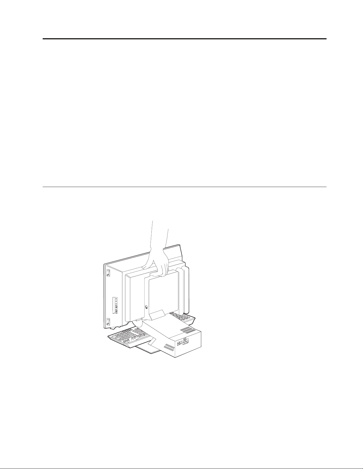
Disconnect all attached device cables from the computer.
you are moving the computer a short distance, you can carry the keyboard
the computer base.
13
Page 22
IR
14
7.
Lift the computer as shown and take care not to let the keyboard slide off the
base.
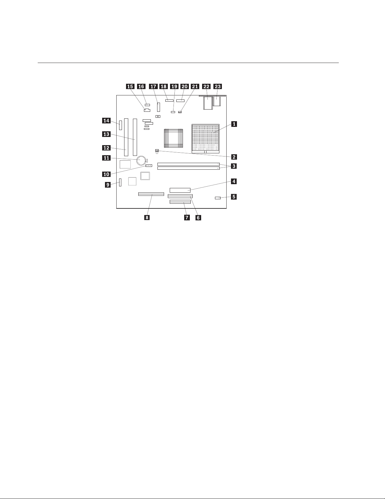
System board layout
3 2 1
1
2
3
4
5
6
7
8
9
Microprocessor connector
System fan connector (not used)
DIMM connectors
Power connector
Inverter connector
CD-ROM drive or DVD drive connector
Diskette drive connector
Hard disk drive connector
LCD connector
10 CMOS clear jumper
11 Battery
12 PCI expansion slot
13 PCI expansion slot
14 Reserved (not used)
15
CD-ROM or DVD-ROM audio connector
16 Speaker connector
17
USB connector
18 BTN (button) connector
19
20 Audio I/O and USB connector
21
Hardware Maintenance Manual
(Infra Red) connector
CPU fan connector (fan located on EMC shield)
Page 23
To
in
Be
22 Ethernet connector
23
PS/2 keyboard and mouse connector.
CMOS Clear jumper settings
CMOS Clear Jumper
1.2
2.3
clear CMOS, see “CMOS Clear Procedure” on page 72.
Processor Speed Settings
Processor FSB speed for the IBM Personal Computer Types 2179 and 6643 are set
the Setup Utility (configuration) program. There are no jumper settings for
processor speed.
System Board Memory
Types 2179 and 6643 use PC133 Non-Parity DIMM memory modules.
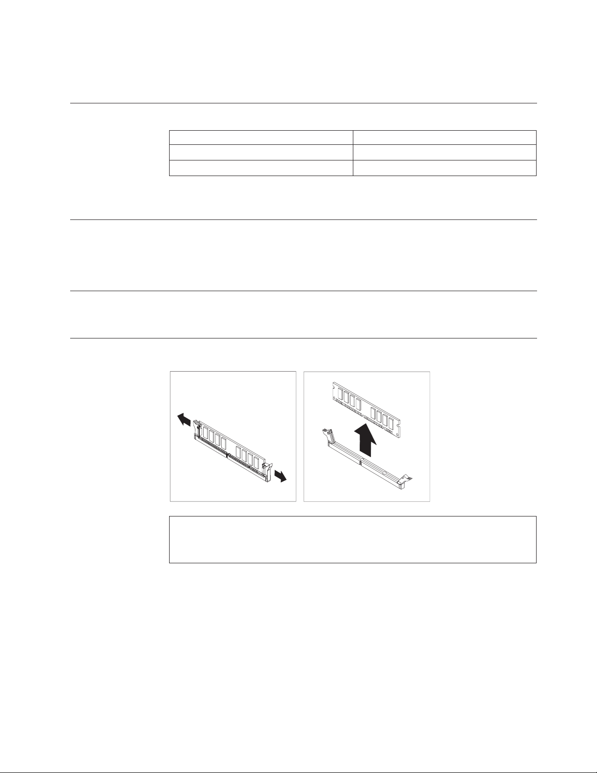
Removing a DIMM
Description
Normal
Clear CMOS
Note:
careful not to push too hard on the retaining clips, because the DIMM might eject too
quickly.
Chapter 4. FRU replacements
15
Page 24
1.
2.
If
v
v
v
v
If
1
2
3
4 5 V +5 V dc 16
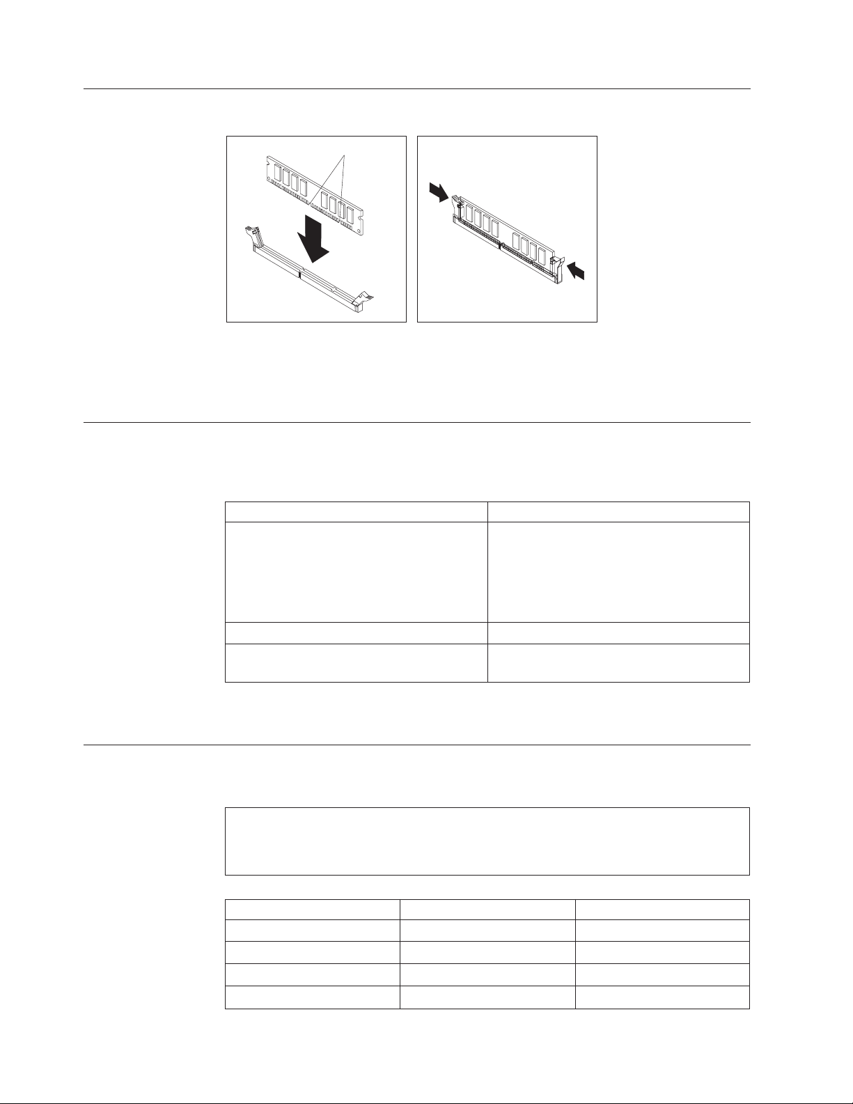
Installing a DIMM
Notches
Position the DIMM above the connector so that the two notches on the bottom
edge of the module align properly with the empty connector.
Firmly push the module straight down into the connector until the retaining
clips pop up and fit snugly around both ends of the module.
Power Supply
the power-on indicator is not on, the power-supply fan is not running, or the
computer will not power-off, do the following:
Check/Verify
Check the following for proper installation.
Power Cord
On/Off Switch connector
System Board Power Supply connectors
microprocessor(s) connection
Check the power cord for proper continuity. Power Cord
Check the power-on switch for continuity
when pressed.
the above are correct, check the following voltages.
20-pin main power supply connection
See “System board layout” on page 14.
Attention:
FRU/Action
Reseat
Power-on Switch
These voltages must be checked with the power supply cables connected to the system
board.
Pin
Hardware Maintenance Manual
Signal
3.3 V
3.3 V
COM
Function
+3.3 V dc
+3.3 V dc
Ground
Page 25
5
6 5 V +5 V dc 7
8
9
10 12 V
11
12
13
14
DC
15
16
17
18 -5 V -5 V dc 19 5 V +5 V dc 20 5 V +5 V dc If
is 8 or
If
1.
2.
3.
If
1.
a.
b.
If
If
1.
2.
3.
If
1.
Pin
Signal
COM
COM
POK
5VSB
3.3 V
-12 V
COM
PS-ON
COM
COM
COM
Function
Ground
Ground
Power Good
Standby Voltage
+12 V dc
+3.3 V dc
-12 V dc
Ground
Remote Enable
Ground
Ground
Ground
Display
the voltages are not correct, and the power cord is good, replace the power
supply.
Note:
The number of defective pixels to qualify a TFT LCD panel to be replaced under warranty
more for all types 2179 and 6643 computers.
the screen has no display (black screen), do the following:
Replace power supply.
Replace inverter card.
Reseat/replace receiver board (receiver board is behind the LCD display.
the screen comes on, then, quickly goes black, do the following:
Check power supply fan. If fan is running:
Replace inverter board.
Replace receiver board.
2.
Power supply fan is not running, replace the power supply.
the screen pallet color is wrong, do the following:
Replace LCD signal cable.
Replace receiver board.
Replace system board.
there are scaling problems, do the following:
Assure latest level video drivers are installed.
Chapter 4. FRU replacements
17
Page 26
If
is 8 or
18
2.
Replace system board.
you are unable to correct the problem, go to “Undetermined problems” on page
56.
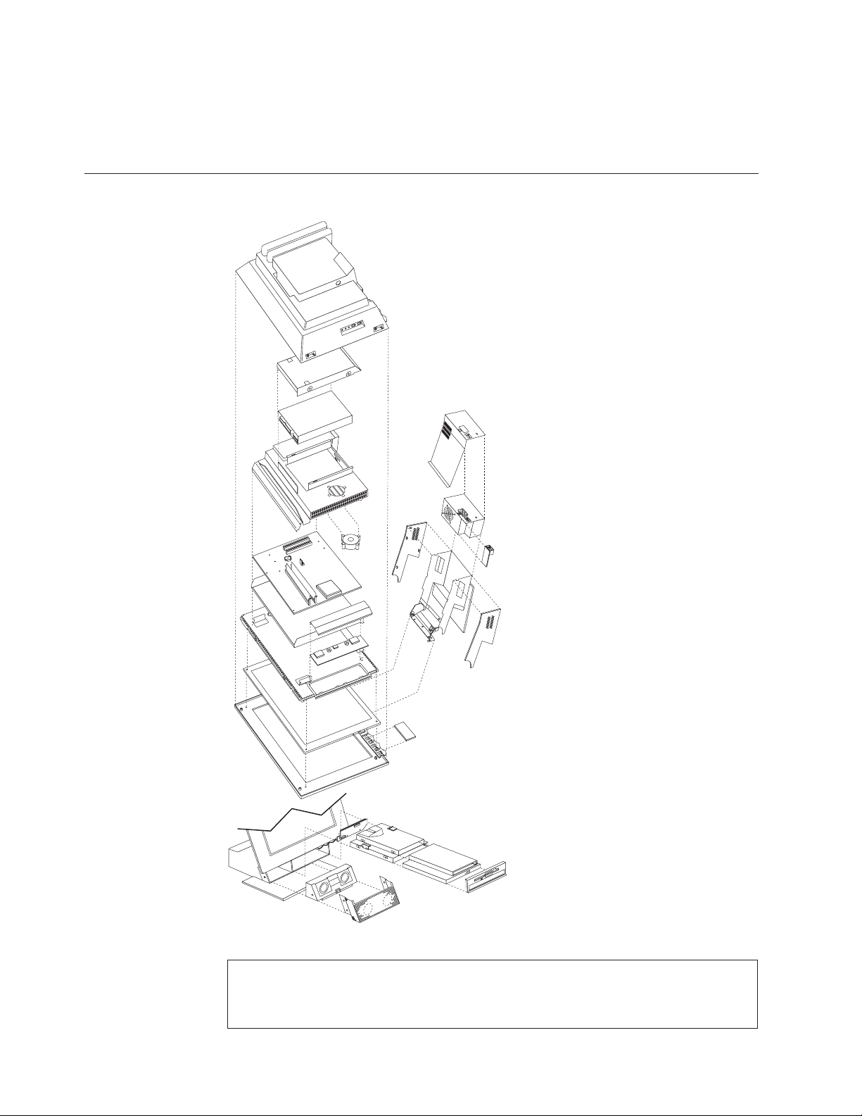
Computer exploded view (Types 2179 and 6643)
I/O connectors and removal procedures are described on the following pages.
Note:
The number of defective pixels to qualify a TFT LCD panel to be replaced under warranty
Hardware Maintenance Manual
more for all types 2179 and 6643 computers.
Page 27
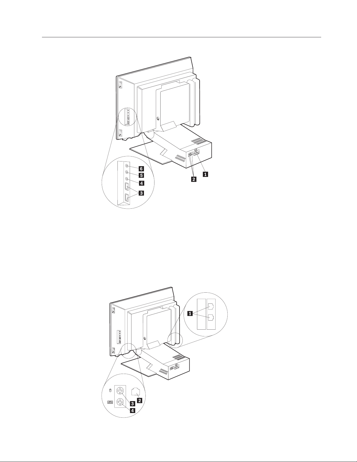
Input/Output connectors
1
2
3
4
5
6
Power connector
USB connector
USB keyboard and mouse connector
Audio line in connector
Audio line out connector
Microphone connector
Chapter 4. FRU replacements
19
Page 28
20
1
2
3
4
Modem connector
Ethernet connector
PS/2 mouse connector
PS/2 keyboard connector
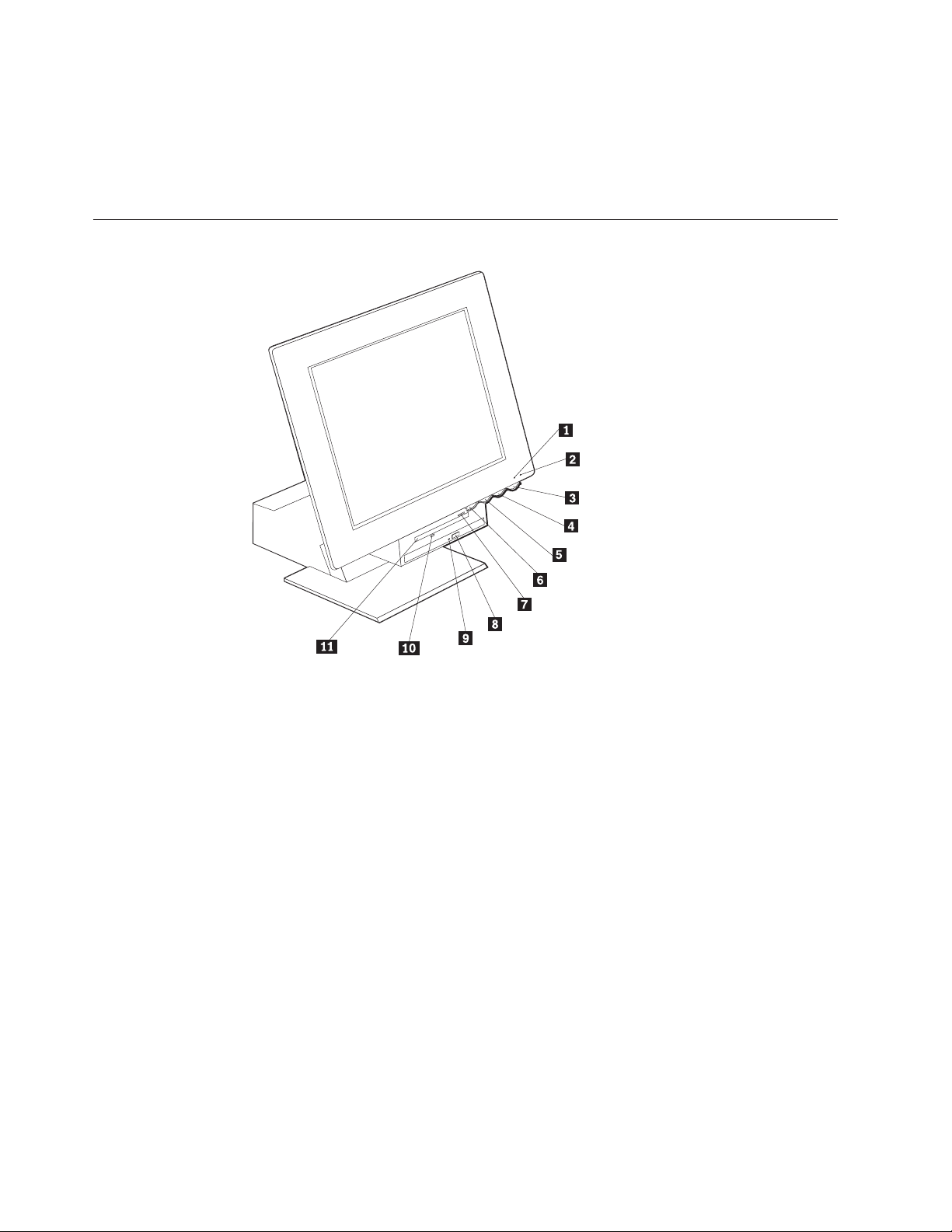
Controls and status indicators
1
2
3
4
5
6
7
8
9
Hard disk drive ″in use″ indicator
Power/Standby indicator
Power button
LCD brightness decrease switch
LCD brightness increase switch
Device bay release button
Diskette eject button
CD-ROM drive or DVD-ROM drive eject button
CD-ROM drive or DVD-ROM drive
10 Diskette drive ″in use″ indicator
11
Diskette drive
Hardware Maintenance Manual
Page 29
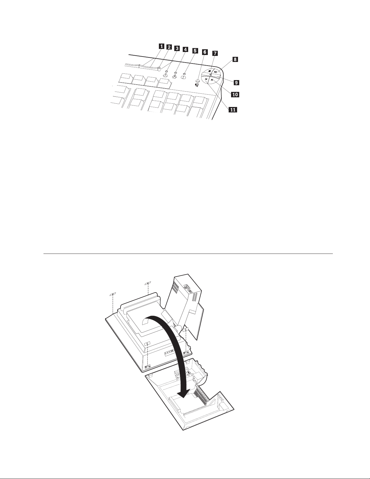
–
+
1
2
3
4
5
6
7
8
9
Standby button
Standby LED
Num Lock LED
Caps Lock LED
Scroll Lock LED
Mute button
Stop button
Play/Pause button
Volume control
10 Next track button
11
Previous track button
Rear bucket housing (rear cover) removal
Chapter 4. FRU replacements
21
Page 30
1.
2.
3.
or
1.
2.
3.
4.
5.
to
to
1.
2.
22
Note:
Before servicing, disconnect all cables attached to the computer.
For proper cooling, do not operate the computer without all covers in place.
When placing the monitor on a flat surface, place it on a padded surface such as cloth
paper towels to protect the monitor and monitor bezel from scratches.
Turn off the computer and all attached devices.
Unplug the power cord.
Pry off the four snap-on screw covers.
Unscrew the four captured screws.
Carefully lift rear bucket housing up to clear the rear EMC cover and rotate it
the position as shown.
Note:
When replacing the rear bucket housing assembly, make sure the small coil spring attached
the device bay release button is properly positioned against the inside of the rear cover.
The device bay release button will not work correctly if the spring is not in the proper
position.
Upper base cover and base cover wing removal
Remove the upper base cover by pulling out on the rear bottom part of the
cover.
Gently pry the two base cover wings from the hinge stand assembly. Note the
positions of the plastic tabs 1.
Hardware Maintenance Manual
Page 31

1.
2. To
3.
4.
1.
Hard disk drive removal
Remove the rear bucket housing, see “Rear bucket housing (rear cover)
removal” on page 21.
release the hard disk drive, use a flat-blade screw driver to pry the latch as
shown.
Rotate the hard disk drive outward, and disconnect the power and signal
cables from the drive.
Lift the hard disk drive up and back to release the hook from the rear EMC
cover.
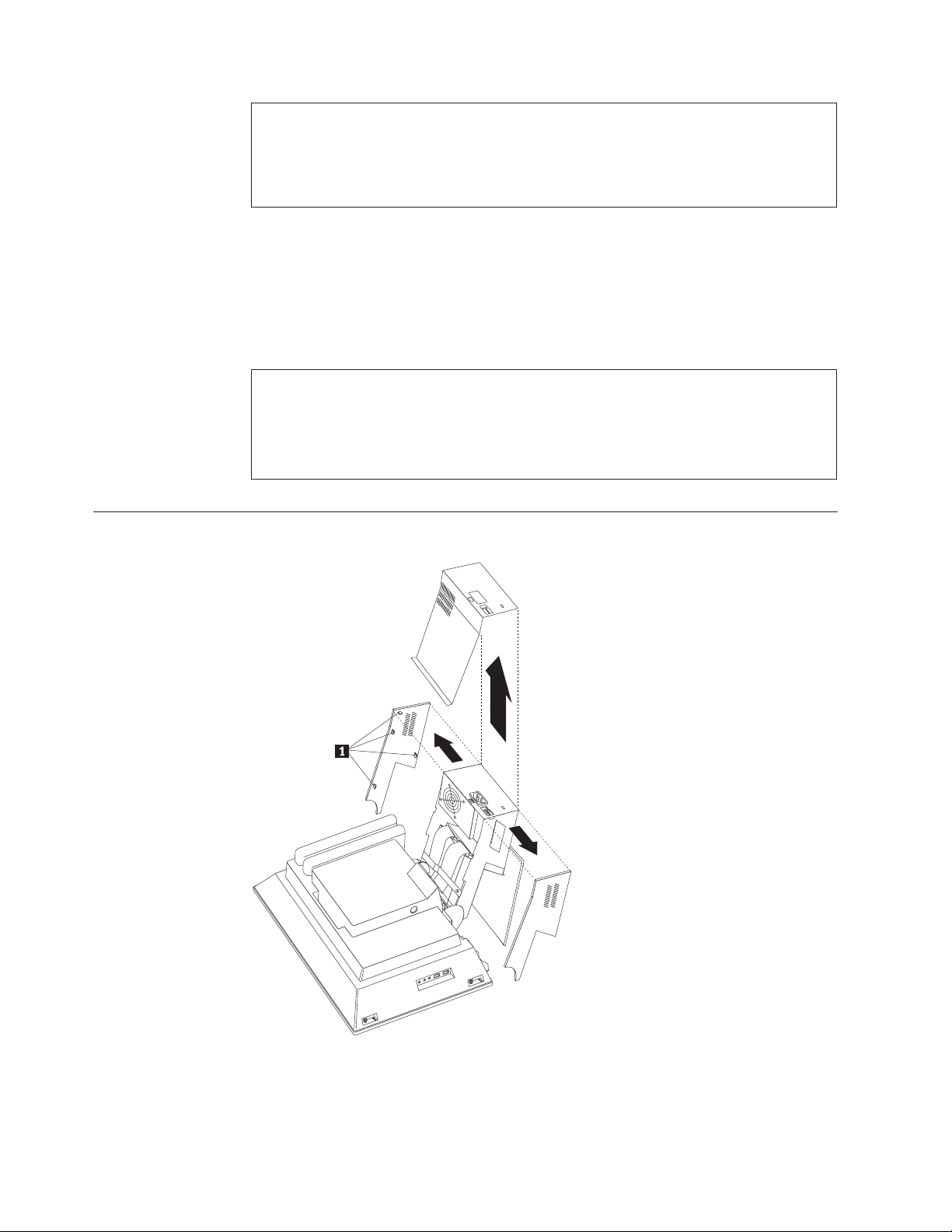
Rear EMC cover assembly removal
The rear EMC cover must be removed in order to remove the system board.
Remove the rear bucket housing, see “Rear bucket housing (rear cover)
removal” on page 21.
Chapter 4. FRU replacements
23
Page 32

3.
1.
2.
3.
4.
5.
6.
7.
1.
2.
3.
24
2.
Remove the four thumb screws holding the system board cover.
Lift the rear EMC cover up and rotate it as shown by the arrow. It is not
necessary to remove the hard disk drive assembly.
Diskette drive/CD-ROM drive/DVD drive removal
Remove the upper base cover, see“Upper base cover and base cover wing
removal” on page 22.
Release the drive unit device bay to the down position.
Remove the device bay bezel by gently pulling it out from both sides.
Unplug the two signal cables from the interface card.
Push the two white plastic release clips on the top and side of the drive
assembly forward to release the drive assembly from the device bay.
Unplug the other two cables (power and speaker) from the interface card.
Remove the drive bracket assembly from the front of the device bay.
Removing the drives from the drive bracket assembly
Unplug the back interface card from the drives.
Remove the eight screws from both drives.
Pull drives out from the drive bracket assembly.
Hardware Maintenance Manual
Page 33

1.
2.
3.
4.
5.
6.
7.
8.
9.
1.
2.
3.
4.
5.
6.
Speaker assembly removal
Remove the upper base cover, see “Upper base cover and base cover wing
removal” on page 22.
Remove both left and right base cover wings.
Remove two side screws that secure the metal speaker grill.
Place the LCD down on a soft covered flat surface.
Remove the bottom plate stand (6 screws).
Remove the rear bucket housing, see “Rear bucket housing (rear cover)
removal” on page 21.
Remove the rear EMC cover, see “Rear EMC cover assembly removal” on
page 23.
Remove the two speaker cables from the system board.
Remove two side screws holding the speaker assembly.
10.
Pull speaker assembly out through the front opening.
Battery removal and installation
Turn off the computer and all attached devices.
Unplug the power cord.
Remove the rear bucket housing, see “Rear bucket housing (rear cover)
removal” on page 21.
Locate the battery.
Remove the old battery.
Insert the new battery.
Chapter 4. FRU replacements
25
Page 34

To
1.
2.
3.
26
Fan removal
remove the rear bucket housing-fan do the following:
Remove the rear bucket housing, see “Rear bucket housing (rear cover)
removal” on page 21.
Remove the rear EMC cover assembly, see “Rear EMC cover assembly
removal” on page 23.
Remove the fan assembly (four screws) from the EMC cover assembly.
Power supply removal
Note:
Make sure the power supply voltage switch is set to the proper operating voltage; 115V or
230V.
Hardware Maintenance Manual
Page 35

1.
2.
3.
4.
5.
6.
7.
8.
9.
To remove the power supply, do the following:
Disconnect the power cable.
Remove the two base cover wings and the upper base cover from the hinge
stand assembly, see “Upper base cover and base cover wing removal” on page
22.
Remove the rear EMC cover assembly, see “Rear EMC cover assembly
removal” on page 23.
Disconnect the hard disk drive power cable.
Disconnect the diskette drive power cable.
Disconnect the power supply cable from the system board.
Remove the USB card from the top of the power supply (two screws).
Remove the cable retainer on top of the hinge stand assembly.
Remove the power supply screws.
10.
Lift the power supply up and out of the chassis.
Chapter 4. FRU replacements
27
Page 36

1.
2.
3.
4. If
5.
6.
28
Processor removal
Remove the rear bucket housing, see “Rear bucket housing (rear cover)
removal” on page 21.
Remove the rear EMC cover assembly, see “Rear EMC cover assembly
removal” on page 23.
Release the processor heatsink clip as shown above.
installed, disconnect the processor fan cable.
Lift the processor socket lever to the up position.
Attention: Be careful not to damage the processor pins.
Lift the processor straight up from its socket.
Hardware Maintenance Manual
Page 37

1.
2.
3.
4.
5.
6.
1.
2. Do
System board removal
Remove the rear bucket housing, see “Rear bucket housing (rear cover)
removal” on page 21.
Remove the rear EMC cover assembly, see “Rear EMC cover assembly
removal” on page 23.
Disconnect all cables attached to the system board.
Unplug any installed PCI cards.
Remove the nine system board screws.
Lift the system board from the chassis assembly.
Power inverter board removal
Attention:
Unplug the power cord from the computer before servicing the Power inverter board.
not power on the computer unless the power inverter board cover with insulator is
properly installed.
Chapter 4. FRU replacements
29
Page 38

2.
3.
4.
30
1.
Remove the rear bucket housing, see “Rear bucket housing (rear cover)
removal” on page 21.
Remove the four power inverter board cover screws. Use the tamper resistant
screw driver, IBM part number 19K3624, to remove these screws.
Disconnect the two end cables and the LCD cable from the power inverter
board.
Remove the two screws from the power inverter board.
Hardware Maintenance Manual
Page 39

1.
2.
3.
4.
5.
6.
7.
8.
Chassis assembly removal
Remove the rear bucket housing, see “Rear bucket housing (rear cover)
removal” on page 21.
Remove the rear EMC cover assembly, see “Rear EMC cover assembly
removal” on page 23.
Disconnect all cables attached to the system board.
Unplug any installed PCI cards.
Remove the nine system board screws.
Lift the system board from the chassis assembly.
Remove the two screws as shown.
Pull the chassis assembly forward, then up to remove it from the LCD housing
assembly.
Chapter 4. FRU replacements
31
Page 40

1.
2.
3.
32
Front bezel removal
LCD removal
Remove the rear bucket housing, see “Rear bucket housing (rear cover)
removal” on page 21.
Remove the four corner screws securing the bezel to the LCD housing
assembly.
Gently pull the bezel from the LCD housing. Note the plastic tabs on the bezel.
Hardware Maintenance Manual
Page 41

v
v
v Be
8 or
1.
2.
3.
4.
5.
6. As
7.
8.
1.
2.
3.
Notes:
Protect the LCD panel from being scratched.
Lay the LCD panel down on a flat clean surface over a cloth or other soft material that
will protect it from being scratched.
careful not to allow other items to come close to the LCD panel as those items might
touch the panel and scratch it.
Note:
The number of defective pixels to qualify a TFT LCD panel to be replaced under warrant is
more for all types 2179 and 6643 computers.
Remove the rear bucket housing, see “Rear bucket housing (rear cover)
removal” on page 21.
Remove the four corner screws securing the bezel to the LCD housing
assembly.
Gently pull the bezel from the LCD housing. Note the plastic tabs on the bezel.
Unplug the top and bottom LCD connectors from the power inverter card.
Remove the four corner screws from the front of the LCD panel to remove the
LCD panel to remove the LCD panel.
you remove the LCD panel, feed the cables through the holes on the LCD
housing assembly.
Unplug the cable to the Receiver card.
The LCD panel can now be removed.
LCD Receiver card removal
Perform the previous LCD removal procedure, see “LCD removal” on page 32.
Remove the two screws from the receiver card being careful to keep the plastic
screw washers and the plastic stand-offs.
Lift up on the receiver card to unplug it from the LCD panel.
Chapter 4. FRU replacements
33
Page 42

1.
2.
3.
4.
5.
1.
2.
3.
4.
5.
6.
7.
8.
34
Installing the Receiver card
Lay the LCD panel on a flat protected surface.
Put each stand-off on the threaded holes of the LCD panel.
Place the receiver card over the stand-offs and by visual site line up the
receiver card holes with the stand-offs.
Lower the receiver card down on the stand-offs and put mild pressure on the
left side of the card in order to seat the card into its connectors.
Install the two screws with the plastic washers into the two mounting holes of
the receiver card to secure the card to the LCD panel.
Hinge assembly removal
Remove the rear bucket housing, see “Rear bucket housing (rear cover)
removal” on page 21.
Remove the rear EMC cover assembly, see “Rear EMC cover assembly
removal” on page 23.
Remove the upper base cover, see “Upper base cover and base cover wing
removal” on page 22.
Remove left and right base cover wings.
Disconnect the two signal cables from the system board that connects to the
diskette drive and CD-ROM drive.
Disconnect the power supply cables from the system board.
Disconnect the USB card cable from the system board.
Remove the three screws from the hinge assembly being careful to hold and
support either assembly so it will not drop.
Hardware Maintenance Manual
Page 43

1.
2.
3.
v
v A
v
v A
v
4
1
1.
2.
3.
3
1.
2.
4
1.
2.
5
1.
2.
6
1.
2.
©
Chapter 5. Symptom-to-FRU Index
Beep symptoms . . . . . . . . . . . . .35
Hard disk drive boot error . . . . . . . . .36
IBM Enhanced Diagnostic error codes . . . . .37
The Symptom-to-FRU index lists error symptoms and possible causes. The most
likely cause is listed first. Always begin with Chapter 2, “General information,” on
page 3. This index can also be used to help you decide which FRUs to have
available when servicing a computer. If you are unable to correct the problem
using this index, go to “Undetermined problems” on page 56.
Important:
Types 2179 and 6643 computers come up quiet (no beep and no memory count and
checkpoint code display) when no errors are detected.
Use Beep codes and the IBM Enhanced Diagnostics to diagnose and fix problems.
The processor is a separate FRU from the system board; the processor is not included
with the system board FRU.
Beep symptoms
Beep symptoms are short tones or a series of short tones separated by pauses
(intervals without sound). See the following examples.
Beeps
1-2-X
POST error codes . . . . . . . . . . . .54
Undetermined problems . . . . . . . . . .56
Description
One beep
pause (or break)
Two beeps
pause (or break)
Any number of breaks
Four continuous beeps
Copyright IBM Corp. 2004
Use the following table to diagnose beep symptoms.
Beep Symptom
Refresh failure
Base 64KB memory failure
Timer not operational
Processor error
8042-Gate A20 failure
FRU/Action
Run IBM Enhanced Diagnostics
Memory module
System board
Memory module
System board
Memory module
System board
Processor
System Board
System Board
Keyboard
35
Page 44

7
1.
2.
8
1.
2.
9
1.
10
1.
11
1.
A
No
1.
2.
3. Go to
36
Beep Symptom
Processor exception interrupt error
Display memory read/write error
ROM Checksum error
CMOS shutdown register read/write error
Cache error/External Cache bad
Hard disk drive boot error
hard disk drive boot error (error codes 1962 and I999030X) can have the
following causes.
Error
The start-up drive is not in the boot
sequence in configuration.
operating system installed on the boot
drive.
The boot sector on the start-up drive is
corrupted.
The drive is defective.
FRU/Action
Processor
System Board
Memory module
System Board
System Board
System Board
System Board
FRU/Action
Check the configuration and ensure the
start-up drive is in the boot sequence.
Install an operating system on the boot
drive.
The drive must be formatted, do the
following:
Attempt to access and recover (back-up)
the failing hard disk drive.
Using the operating systems programs,
format the hard disk drive.
“Preparing the hard disk drive for
use” on page 12.
Replace the hard disk drive.
Hardware Maintenance Manual
Page 45

In
1. No
1.
2.
1.
2.
1.
2.
3.
1.
2.
3.
1.
2.
3.
4.
1.
2.
3.
4.
1.
2.
1.
2.
3.
1.
2.
3.
1.
2.
1.
2.
1.
2.
IBM Enhanced Diagnostic error codes
Refer to the following diagnostic error codes when using the diagnostic tests. See
“Diagnostics and test information” on page 5 for the specific type for information
about the diagnostic programs.
the following index, X can represent any number.
Diagnostic Error Code
000-000-XXX
BIOS Test Passed
000-002-XXX
BIOS Timeout
000-024-XXX
BIOS Addressing test failure
000-025-XXX
BIOS Checksum Value error
000-026-XXX
FLASH data error
000-027-XXX
BIOS Configuration/Setup error
000-034-XXX
BIOS Buffer Allocation failure
000-035-XXX
BIOS Reset Condition detected
000-036-XXX
BIOS Register error
000-038-XXX
BIOS Extension failure
000-039-XXX
BIOS DMI data error
000-195-XXX
BIOS Test aborted by user
000-196-XXX
BIOS test halt, error threshold exceeded
FRU/Action
action
Flash the system
System board
Flash the system
System board
Flash the system
Boot block
System board
Flash the system
Boot block
System board
Run Setup
Flash the system
Boot block
System board
Reboot the system
Flash the system
Run memory test
System board
Flash the system
System board
Flash the system
Boot block
System board
Flash the system
Adapter card
System board
Flash the system
System board
Information
Re-start the test, if necessary
Press F3 to review the log file
Re-start the test to reset the log file
Chapter 5. Symptom-to-FRU Index
37
Page 46

1.
2.
3.
4.
1. If a
it is
2.
3. Go to
1. Go to
2.
3.
1.
2.
1.
2.
1. No
1.
1.
1.
1.
2.
1.
2.
1.
2.
3.
1.
1.
2.
3.
4.
1.
1.
38
Diagnostic Error Code
000-197-XXX
BIOS test warning
000-198-XXX
BIOS test aborted
000-199-XXX
BIOS test failed, cause unknown
000-250-XXX
BIOS APM failure
000-270-XXX
BIOS ACPI failure
001-000-XXX
System Test Passed
001-00X-XXX
System Error
001-01X-XXX
System Error
001-024-XXX
System Addressing test failure
001-025-XXX
System Checksum Value error
001-026-XXX
System FLASH data error
001-027-XXX
System Configuration/Setup error
001-032-XXX
System Device Controller failure
001-034-XXX
System Device Buffer Allocation failure
001-035-XXX
System Device Reset condition detected
001-036-XXX
System Register error
FRU/Action
Make sure the component that is called
out is connected and/or enabled
Re-run test
Component that is called out in warning
statement
Component under test
component is called out, make sure
connected and/or enabled
Flash the system and re-test
the ″Undetermined problems″
section
the ″Undetermined problems″
section
Flash the system and re-test
Replace component under function test
Flash the system
System board
Flash the system
System board
action
System board
System board
System board
Flash the system
System board
Flash the system
System board
Run Setup
Flash the system
System board
System board
Reboot the system
Flash the system
Run memory test
System board
System board
System board
Hardware Maintenance Manual
Page 47

1.
2.
1.
2.
1.
2.
1.
2.
1.
2.
1.
2.
1.
2.
3.
4.
1. If a
it is
2.
3. Go to
1. Go to
2.
3.
1.
1.
1.
1.
2.
1.
2.
1.
2.
Diagnostic Error Code
001-038-XXX
System Extension failure
001-039-XXX
System DMI data structure error
001-040-XXX
System IRQ failure
001-041-XXX
System DMA failure
001-195-XXX
System Test aborted by user
001-196-XXX
System test halt, error threshold exceeded
001-197-XXX
System test warning
001-198-XXX
System test aborted
001-199-XXX
System test failed, cause unknown
001-250-XXX
System ECC error
001-254-XXX
001-255-XXX
001-256-XXX
001-257-XXX
System DMA error
001-260-XXX
001-264-XXX
System IRQ error
001-268-XXX
System IRQ1 failure
001-269-XXX
System IRQ2 failure
001-270-XXX
System IRQ3 failure
FRU/Action
Adapter card
System board
Flash the system
System board
Power-off/on system and re-test
System board
Power-off/on system and re-test
System board
Information
Re-start the test, if necessary
Press F3 to review the log file
Re-start the test to reset the log file
Make sure the component that is called
out is connected and/or enabled
Re-run test
Component that is called out in warning
statement
Component under test
component is called out, make sure
connected and/or enabled
Flash the system and re-test
the ″Undetermined problems″
section
the ″Undetermined problems″
section
Flash the system and re-test
Replace component under function test
System board
System board
System board
Device on IRQ1
System board
Device on IRQ2
System board
Device on IRQ3
System board
Chapter 5. Symptom-to-FRU Index
39
Page 48

1.
2.
1.
2.
1.
2.
3.
1.
2.
1.
2.
1.
2.
1.
2.
1.
2.
1.
2.
1.
2.
1.
2.
3.
1.
2.
1.
1.
2.
1.
2.
1.
2.
1.
1.
40
Diagnostic Error Code
001-271-XXX
System IRQ4 failure
001-272-XXX
System IRQ5 failure
001-273-XXX
System IRQ6
(diskette drive) failure
001-274-XXX
System IRQ7 failure
001-275-XXX
System IRQ8 failure
001-276-XXX
System IRQ9 failure
001-277-XXX
System IRQ10 failure
001-278-XXX
System IRQ11 failure
001-279-XXX
System IRQ12 failure
001-280-XXX
System IRQ13 failure
001-281-XXX
System IRQ14
(hard disk drive) failure
001-282-XXX
System IRQ15 failure
001-286-XXX
001-287-XXX
001-288-XXX
System Timer failure
001-292-XXX
System CMOS
RAM error
001-293-XXX
System CMOS Battery
001-298-XXX
System RTC date/time update failure
001-299-XXX
System RTC periodic interrupt failure
001-300-XXX
System RTC Alarm failure
FRU/Action
Device on IRQ4
System board
Device on IRQ5
System board
Diskette Cable
Diskette drive
System board
Device on IRQ7
System board
Device on IRQ8
System board
Device on IRQ9
System board
Device on IRQ10
System board
Device on IRQ11
System board
Device on IRQ12
System board
Device on IRQ13
System board
Hard disk drive cable
Hard disk drive
System board
Device on IRQ15
System board
System board
Run Setup and re-test
System board
Battery
System board
Flash the system
System board
System board
System board
Hardware Maintenance Manual
Page 49

1.
2.
1. No
1.
2.
1.
2.
1.
2.
3.
1.
2.
1.
2.
1.
2.
3.
4.
1.
2.
3.
4.
1.
2.
1.
2.
1.
2.
1.
2.
1.
2.
1.
2.
Diagnostic Error Code
001-301-XXX
System RTC Century byte error
005-000-XXX
Video Test Passed
005-00X-XXX
Video error
005-010-XXX
005-011-XXX
005-012-XXX
005-013-XXX
Video Signal failure
005-016-XXX
Video Simple Pattern
test failure
005-024-XXX
Video Addressing test failure
005-025-XXX
Video Checksum Value error
005-027-XXX
Video Configuration/Setup error
005-031-XXX
Video Device Cable failure
005-032-XXX
Video Device Controller failure
005-036-XXX
Video Register error
005-038-XXX
System BIOS extension failure
005-040-XXX
Video IRQ failure
005-195-XXX
Video Test aborted by user
005-196-XXX
Video test halt, error threshold exceeded
FRU/Action
Flash the system
System board
action
Video card, if installed
System board
Video card, if installed
System board
Video Ram
Video card, if installed
System board
Video card, if installed
System board
Video card, if installed
System board
Run Setup
Video drivers update
Video card, if installed
System board
Video cable
Monitor
Video card, if installed
System board
Video card, if installed
System board
Video card, if installed
System board
Video card, if installed
System board
Video card, if installed
System board
Information
Re-start the test, if necessary
Press F3 to review the log file
Re-start the test to reset the log file
Chapter 5. Symptom-to-FRU Index
41
Page 50

1.
2.
3.
4.
1. If a
it is
2.
3. Go to
1. Go to
2.
3.
1.
2.
1. No
1.
2.
3.
1.
2.
1.
2.
1. If a
it is
2.
3.
4.
1. If a
it is
2.
3. Go to
1. Go to
2.
3.
1.
2.
3.
42
Diagnostic Error Code
005-197-XXX
Video test warning
005-198-XXX
Video test aborted
005-199-XXX
Video test failed, cause unknown
005-2XX-XXX
005-3XX-XXX
Video subsystem error
006-000-XXX
Diskette interface Test Passed
006-0XX-XXX
Diskette interface error
006-195-XXX
Diskette interface Test aborted by user
006-196-XXX
Diskette interface test halt, error threshold
exceeded
006-197-XXX
Diskette interface test warning
006-198-XXX
Diskette interface test aborted
006-199-XXX
Diskette interface test failed, cause unknown
006-25X-XXX
Diskette interface Error
FRU/Action
Make sure the component that is called
out is connected and/or enabled
Re-run test
Component that is called out in warning
statement
Component under test
component is called out, make sure
connected and/or enabled
Flash the system and re-test
the ″Undetermined problems″
section
the ″Undetermined problems″
section
Flash the system and re-test
Replace component under function test
Video card, if installed
System board
action
Diskette drive Cable
Diskette drive
System board
Information
Re-start the test, if necessary
Press F3 to review the log file
Re-start the test to reset the log file
component is called out, make sure
connected and/or enabled
Re-run test
Component that is called out in warning
statement
Component under test
component is called out, make sure
connected and/or enabled
Flash the system and re-test
the ″Undetermined problems″
section
the ″Undetermined problems″
section
Flash the system and re-test
Replace component under function test
Diskette drive cable
Diskette drive
System board
Hardware Maintenance Manual
Page 51

1. No
1.
2.
3.
1.
1.
1.
2.
1.
2.
3.
1.
1.
2.
1.
2.
1.
2.
3.
4.
1. If a
it is
2.
3. Go to
1. Go to
2.
3.
1.
2.
1. No
Diagnostic Error Code
011-000-XXX
Serial port Interface Test Passed
011-001-XXX
Serial port Presence
011-002-XXX
011-003-XXX
Serial port Timeout/Parity error
011-013-XXX
011-014-XXX
Serial port Control Signal/Loopback test
failure
011-015-XXX
Serial port External Loopback failure
011-027-XXX
Serial port Configuration/Setup error
011-03X-XXX
011-04X-XXX
Serial port failure
011-195-XXX
Serial port Test aborted by user
011-196-XXX
Serial port test halt, error threshold exceeded
011-197-XXX
Serial port test warning
011-198-XXX
Serial port test aborted
011-199-XXX
Serial port test failed, cause unknown
011-2XX-XXX
Serial port signal failure
014-000-XXX
Parallel port Interface Test Passed
FRU/Action
action
Remove external serial device, if
present
Run setup, enable port
System board
System board
System board
Wrap plug
System board
Run Setup, enable port
Flash the system
System board
System board
Information
Re-start the test, if necessary
Press F3 to review the log file
Re-start the test to reset the log file
Make sure the component that is called
out is connected and/or enabled
Re-run test
Component that is called out in warning
statement
Component under test
component is called out, make sure
connected and/or enabled
Flash the system and re-test
the ″Undetermined problems″
section
the ″Undetermined problems″
section
Flash the system and re-test
Replace component under function test
External serial device
System board
action
Chapter 5. Symptom-to-FRU Index
43
Page 52

1.
2.
3.
1.
1.
1.
2.
1.
2.
3.
1.
1.
2.
1.
2.
1.
2.
3.
4.
1. If a
it is
2.
3. Go to
1. Go to
2.
3.
1.
2.
1. No
1.
2.
44
Diagnostic Error Code
014-001-XXX
Parallel port Presence
014-002-XXX
014-003-XXX
Parallel port Timeout/Parity error
014-013-XXX
014-014-XXX
Parallel port Control Signal/Loopback test
failure
014-015-XXX
Parallel port External Loopback failure
014-027-XXX
Parallel port Configuration/Setup error
014-03X-XXX
014-04X-XXX
Parallel port failure
014-195-XXX
Parallel port Test aborted by user
014-196-XXX
Parallel port test halt, error threshold
exceeded
014-197-XXX
Parallel port test warning
014-198-XXX
Parallel port test aborted
014-199-XXX
Parallel port test failed, cause unknown
014-2XX-XXX
014-3XX-XXX
Parallel port failure
015-000-XXX
USB port Interface Test Passed
015-001-XXX
USB port Presence
FRU/Action
Remove external parallel device, if
present
Run setup, enable port
System board
System board
System board
Wrap plug
System board
Run Setup, enable port
Flash the system
System board
System board
Information
Re-start the test, if necessary
Press F3 to review the log file
Re-start the test to reset the log file
Make sure the component that is called
out is connected and/or enabled
Re-run test
Component that is called out in warning
statement
Component under test
component is called out, make sure
connected and/or enabled
Flash the system and re-test
the ″Undetermined problems″
section
the ″Undetermined problems″
section
Flash the system and re-test
Replace component under function test
External parallel device
System board
action
Remove USB device(s) and re-test
System board
Hardware Maintenance Manual
Page 53

1.
2.
1.
2.
1.
2.
1.
1.
2.
3.
4.
1.
2.
1.
1.
2.
3.
1.
2.
1.
2.
1.
2.
3.
4.
1. If a
it is
2.
3. Go to
1. Go to
2.
3.
1. No
1.
2.
Diagnostic Error Code
015-002-XXX
USB port Timeout
015-015-XXX
USB port External Loopback failure
015-027-XXX
USB port Configuration/Setup error
015-032-XXX
USB port Device Controller failure
015-034-XXX
USB port buffer
allocation failure
015-035-XXX
USB port Reset condition detected
015-036-XXX
USB port Register error
015-040-XXX
USB port IRQ failure
015-195-XXX
USB port Test aborted by user
015-196-XXX
USB port test halt, error threshold exceeded
015-197-XXX
USB port test warning
015-198-XXX
USB port test aborted
015-199-XXX
USB port test failed, cause unknown
018-000-XXX
PCI Card Test Passed
018-0XX-XXX
PCI Card Failure
FRU/Action
Remove USB device(s) and re-test
System board
Remove USB device(s) and re-test
System board
Flash the system
System board
System board
Reboot the system
Flash the system
Run memory test
System board
Remove USB device(s) and re-test
System board
System board
Run setup and check for conflicts
Flash the system
System board
Information
Re-start the test, if necessary
Press F3 to review the log file
Re-start the test to reset the log file
Make sure the component that is called
out is connected and/or enabled
Re-run test
Component that is called out in warning
statement
Component under test
component is called out, make sure
connected and/or enabled
Flash the system and re-test
the ″Undetermined problems″
section
the ″Undetermined problems″
section
Flash the system and re-test
Replace component under function test
action
Riser card if installed
System board
Chapter 5. Symptom-to-FRU Index
45
Page 54

1.
2.
3.
1.
2.
1.
2.
3.
4.
1.
2.
3. Go to
1. Go to
2.
3.
1.
2.
3.
1. No
1.
2.
3.
1.
2.
1.
2.
1.
2.
3.
4.
1. If a
it is
2.
3. Go to
46
Diagnostic Error Code
018-195-XXX
PCI Card Test aborted by user
018-196-XXX
PCI Card test halt, error threshold exceeded
018-197-XXX
PCI Card test warning
018-198-XXX
PCI Card test aborted
018-199-XXX
PCI Card test failed, cause unknown
018-250-XXX
PCI Card Services error
020-000-XXX
PCI Interface Test Passed
020-0XX-XXX
PCI Interface error
020-195-XXX
PCI Test aborted by user
020-196-XXX
PCI test halt, error threshold exceeded
020-197-XXX
PCI test warning
020-198-XXX
PCI test aborted
FRU/Action
PCI card
Information
Re-start the test, if necessary
Press F3 to review the log file
Re-start the test to reset the log file
Make sure the component that is called
out is connected and/or enabled
Re-run test
Component that is called out in warning
statement
Component under test
Make sure the component that is called
out is connected and/or enabled
Flash the system and re-test
the ″Undetermined problems″
section
the ″Undetermined problems″
section
Flash the system and re-test
Replace component under function test
PCI card
Riser card, if installed
System board
action
PCI card
Riser card, if installed
System board
Information
Re-start the test, if necessary
Press F3 to review the log file
Re-start the test to reset the log file
Make sure the component that is called
out is connected and/or enabled
Re-run test
Component that is called out in warning
statement
Component under test
component is called out, make sure
connected and/or enabled
Flash the system and re-test
the ″Undetermined problems″
section
Hardware Maintenance Manual
Page 55

1. Go to
2.
3.
1.
2.
3.
1. No
1.
2.
3.
4.
1.
2.
3.
4.
1.
2.
3.
4.
1.
2.
1.
2.
1.
2.
3.
4.
1. If a
it is
2.
3. Go to
1. Go to
2.
3.
1. No
Diagnostic Error Code
020-199-XXX
PCI test failed, cause unknown
020-262-XXX
system error
PCI
025-000-XXX
interface Test Passed
IDE
025-00X-XXX
025-01X-XXX
IDE interface failure
025-027-XXX
IDE interface Configuration/Setup error
025-02X-XXX
025-03X-XXX
025-04X-XXX
IDE Interface failure
025-195-XXX
IDE interface Test aborted by user
025-196-XXX
IDE interface test halt, error threshold
exceeded
025-197-XXX
IDE interface test warning
025-198-XXX
IDE interface test aborted
025-199-XXX
IDE interface test failed, cause unknown
030-000-XXX
SCSI interface Test Passed
FRU/Action
the ″Undetermined problems″
section
Flash the system and re-test
Replace component under function test
PCI card
Riser card, if installed
System board
action
IDE signal cable
Check power supply
IDE device
System board
IDE signal cable
Flash the system
IDE device
System board
IDE signal cable
Check power supply
IDE device
System board
Information
Re-start the test, if necessary
Press F3 to review the log file
Re-start the test to reset the log file
Make sure the component that is called
out is connected and/or enabled
Re-run test
Component that is called out in warning
statement
Component under test
component is called out, make sure
connected and/or enabled
Flash the system and re-test
the ″Undetermined problems″
section
the ″Undetermined problems″
section
Flash the system and re-test
Replace component under function test
action
Chapter 5. Symptom-to-FRU Index
47
Page 56

1.
2.
3.
4.
5.
1.
2.
3.
4.
5.
1.
2.
3.
4.
5.
1.
2.
1.
2.
1.
2.
3.
4.
1. If a
it is
2.
3. Go to
1. Go to
2.
3.
1. No
1.
2.
3.
4.
1.
2.
48
Diagnostic Error Code
030-00X-XXX
030-01X-XXX
SCSI interface failure
030-027-XXX
SCSI interface Configuration/Setup error
030-03X-XXX
030-04X-XXX
SCSI interface error
030-195-XXX
SCSI interface Test aborted by user
030-196-XXX
SCSI interface test halt, error threshold
exceeded
030-197-XXX
SCSI interface test warning
030-198-XXX
SCSI interface test aborted
030-199-XXX
SCSI interface test failed, cause unknown
035-000-XXX
RAID interface Test Passed
035-0XX-XXX
RAID interface Failure
035-195-XXX
RAID interface Test aborted by user
FRU/Action
SCSI signal cable
Check power supply
SCSI device
SCSI adapter card, if installed
System board
SCSI signal cable
Flash the system
SCSI device
SCSI adapter card, if installed
System board
SCSI signal cable
Check power supply
SCSI device
SCSI adapter card, if installed
installed System board
Information
Re-start the test, if necessary
Press F3 to review the log file
Re-start the test to reset the log file
Make sure the component that is called
out is connected and/or enabled
Re-run test
Component that is called out in warning
statement
Component under test
component is called out, make sure
connected and/or enabled
Flash the system and re-test
the ″Undetermined problems″
section
the ″Undetermined problems″
section
Flash the system and re-test
Replace component under function test
action
RAID signal cable
RAID device
RAID adapter card, if installed
System board
Information
Re-start the test, if necessary
Hardware Maintenance Manual
Page 57

1.
2.
1.
2.
3.
4.
1. If a
it is
2.
3. Go to
1. Go to
2.
3.
1. No
1.
2.
3.
1.
2.
3.
4.
1.
2.
3.
1.
2.
1.
2.
1.
2.
3.
4.
1. If a
it is
2.
3. Go to
Diagnostic Error Code
035-196-XXX
RAID interface test halt, error threshold
exceeded
035-197-XXX
RAID interface test warning
035-198-XXX
RAID interface test aborted
035-199-XXX
RAID interface test failed, cause unknown
071-000-XXX
Audio port Interface Test Passed
071-00X-XXX
071-01X-XXX
071-02X-XXX
port error
Audio
071-03X-XXX
Audio port failure
071-04X-XXX
Audio port failure
071-195-XXX
Audio port Test aborted by user
071-196-XXX
Audio port test halt, error threshold
exceeded
071-197-XXX
Audio port test warning
071-198-XXX
Audio port test aborted
FRU/Action
Press F3 to review the log file
Re-start the test to reset the log file
Make sure the component that is called
out is connected and/or enabled
Re-run test
Component that is called out in warning
statement
Component under test
component is called out, make sure
connected and/or enabled
Flash the system and re-test
the ″Undetermined problems″
section
the ″Undetermined problems″
section
Flash the system and re-test
Replace component under function test
action
Run Setup
Flash the system
System board
Speakers
Microphone
Audio card, if installed
System board
Run Setup
Audio card, if installed
System board
Information
Re-start the test, if necessary
Press F3 to review the log file
Re-start the test to reset the log file
Make sure the component that is called
out is connected and/or enabled
Re-run test
Component that is called out in warning
statement
Component under test
component is called out, make sure
connected and/or enabled
Flash the system and re-test
the ″Undetermined problems″
section
Chapter 5. Symptom-to-FRU Index
49
Page 58

1. Go to
2.
3.
1.
2.
3.
1. No
1.
1.
2.
1.
2.
1.
2.
3.
4.
1. If a
it is
2.
3. Go to
1. Go to
2.
3.
1. No
1.
2.
1.
2.
1.
2.
1.
2.
3.
1.
2.
50
Diagnostic Error Code
071-199-XXX
Audio port test failed, cause unknown
071-25X-XXX
Audio port failure
080-000-XXX
Game Port interface Test Passed
080-XXX-XXX
Game Port interface Error
080-195-XXX
Game Port interface Test aborted by user
080-196-XXX
Game Port interface test halt, error threshold
exceeded
080-197-XXX
Game Port interface test warning
080-198-XXX
Game Port interface test aborted
080-199-XXX
Game Port interface test failed, cause
unknown
086-000-XXX
Mouse Port interface Test Passed
086-001-XXX
Mouse Port interface Presence
086-032-XXX
Mouse Port interface Device controller
failure
086-035-XXX
Mouse Port interface Reset
086-040-XXX
Mouse Port interface IRQ failure
086-195-XXX
Mouse Port interface Test aborted by user
FRU/Action
the ″Undetermined problems″
section
Flash the system and re-test
Replace component under function test
Speakers
Audio card, if installed
System board
action
Remove the game port device and
re-test the system
Information
Re-start the test, if necessary
Press F3 to review the log file
Re-start the test to reset the log file
Make sure the component that is called
out is connected and/or enabled
Re-run test
Component that is called out in warning
statement
Component under test
component is called out, make sure
connected and/or enabled
Flash the system and re-test
the ″Undetermined problems″
section
the ″Undetermined problems″
section
Flash the system and re-test
Replace component under function test
action
Mouse
System board
Mouse
System board
Mouse
System board
Run Setup
Mouse
System board
Information
Re-start the test, if necessary
Hardware Maintenance Manual
Page 59

1.
2.
1.
2.
3.
4.
1. If a
is
2.
3. Go to
1. Go to
2.
3.
1. No
1.
2.
1.
2.
1.
2.
1.
2.
3.
4.
1.
2. Go to
1. If a
it is
2. Go to
3.
4.
1. No
1.
2.
Diagnostic Error Code
086-196-XXX
Mouse Port interface test halt, error
threshold exceeded
086-197-XXX
Mouse Port interface test warning
086-198-XXX
Mouse Port interface test aborted
086-199-XXX
Mouse Port interface test failed, cause
unknown
089-000-XXX
Microprocessor Test Passed
089-XXX-XXX
Microprocessor failure
089-195-XXX
Microprocessor Test aborted by user
089-196-XXX
Microprocessor test halt, error threshold
exceeded
089-197-XXX
Microprocessor test warning
089-198-XXX
Microprocessor test aborted
089-199-XXX
Microprocessor test failed, cause unknown
170-000-XXX
Voltage Sensor(s) Test Passed
170-0XX-XXX
Voltage Sensor(s) failure
FRU/Action
Press F3 to review the log file
Re-start the test to reset the log file
Make sure the component that is called
out is connected and/or enabled
Re-run test
Component that is called out in warning
statement
Component under test
component is called out, make sure it
connected and/or enabled
Flash the system and re-test
the ″Undetermined problems″
section
the ″Undetermined problems″
section
Flash the system and re-test
Replace component under function test
action
Microprocessor(s)
System board
Information
Re-start the test, if necessary
Press F3 to review the log file
Re-start the test to reset the log file
Make sure the component that is called
out is connected and/or enabled
Re-run test
Component that is called out in warning
statement
Component under test
Flash the system and re-test
the ″Undetermined problems″
section
component is called out, make sure
connected and/or enabled
the ″Undetermined problems″
section
Flash the system and re-test
Replace component under function test
action
Flash system
System board
Chapter 5. Symptom-to-FRU Index
51
Page 60

1.
2.
1.
2.
1.
2.
3.
4.
1. If a
it is
2.
3. Go to
1. Go to
2.
3.
1.
2.
1.
2.
3.
1. No
1.
2.
1.
2.
1.
2.
1.
2.
3.
4.
1. If a
it is
2.
3. Go to
52
Diagnostic Error Code
170-195-XXX
Voltage Sensor(s) Test aborted by user
170-196-XXX
Voltage Sensor(s) test halt, error threshold
exceeded
170-197-XXX
Voltage Sensor(s) test warning
170-198-XXX
Voltage Sensor(s) test aborted
170-199-XXX
Voltage Sensor(s) test failed, cause unknown
170-250-XXX
170-251-XXX
Voltage Sensor(s) Voltage limit error
170-254-XXX
Voltage Sensor(s) Voltage Regulator Module
error
175-000-XXX
Thermal Sensor(s) Test Passed
175-0XX-XXX
Thermal Sensor(s) failure
175-195-XXX
Thermal Sensor(s) Test aborted by user
175-196-XXX
Thermal Sensor(s) test halt, error threshold
exceeded
175-197-XXX
Thermal Sensor(s) test warning
175-198-XXX
Thermal Sensor(s) test aborted
FRU/Action
Information
Re-start the test, if necessary
Press F3 to review the log file
Re-start the test to reset the log file
Make sure the component that is called
out is connected and/or enabled
Re-run test
Component that is called out in warning
statement
Component under test
component is called out, make sure
connected and/or enabled
Flash the system and re-test
the ″Undetermined problems″
section
the ″Undetermined problems″
section
Flash the system and re-test
Replace component under function test
Power supply
System board
Voltage Regulator Module (VRM)
Microprocessor
System board
action
Flash system
System board
Information
Re-start the test, if necessary
Press F3 to review the log file
Re-start the test to reset the log file
Make sure the component that is called
out is connected and/or enabled
Re-run test
Component that is called out in warning
statement
Component under test
component is called out, make sure
connected and/or enabled
Flash the system and re-test
″Undetermined problems″ section
Hardware Maintenance Manual
Page 61

1. Go to
2.
3.
1.
2.
3.
4.
1. No
1.
2.
1.
2. C2
3.
1. No
1.
by
2.
1. No
1.
2.
3.
1. No
1.
2.
3.
4.
1. No
1.
2.
3.
4.
1. No
1.
2.
3.
4.
Diagnostic Error Code
175-199-XXX
Thermal Sensor(s) test failed, cause
unknown
175-250-XXX
175-251-XXX
Thermal Sensor(s) limit error
185-000-XXX
Asset Security Test Passed
185-XXX-XXX
Asset Security failure
185-278-XXX
Asset Security Chassis Intrusion
201-000-XXX
System Memory Test Passed
201-XXX-XXX
System Memory error
202-000-XXX
System Cache Test Passed
202-XXX-XXX
System Cache error
206-000-XXX
Diskette Drive Test Passed
206-XXX-XXX
Diskette Drive error
215-000-XXX
CD-ROM Drive Test Passed
215-XXX-XXX
CD-ROM Drive error
217-000-XXX
Hard Disk Drive Test Passed
217-25X-XXX
217-26X-XXX
Hard Disk Drive (IDE) error
FRU/Action
the ″Undetermined problems″
section
Flash the system and re-test
Replace component under function test
Check fans
Check Power supply
Microprocessor
System board
action
Flash system
System board
Assure Asset Security Enabled
Cover Switch
System board
action
Replace the memory module called out
the test
System board
action
Cache, if removable
System board
Microprocessor
action
Diskette Drive Cable
Check power supply voltages
Diskette drive
System board
action
CD-ROM Drive Cable
Check power supply voltages
CD-ROM drive
System board
action
Hard Disk Drive Cable
Check power supply voltages
Hard Disk drive (IDE)
System board
Chapter 5. Symptom-to-FRU Index
53
Page 62

1.
2.
3.
4.
5.
1. No
1.
1.
2.
3.
1. No
1. No
1.
2.
3.
1. No
1.
1. No
1.
2.
3.
4.
5.
1. No
1.
v
v
v
v
v
54
Diagnostic Error Code
217-28X-XXX
217-29X-XXX
Hard Disk Drive (SCSI) error
220-000-XXX
Hi-Capacity Cartridge Drive Test Passed
220-XXX-XXX
Hi-Capacity Cartridge Drive error
301-XXX-XXX
Keyboard error
301-000-XXX
Keyboard Test Passed
302-000-XXX
Mouse Test Passed
302-XXX-XXX
Mouse error
303-000-XXX
Joystick Test Passed
303-XXX-XXX
Joystick error
305-000-XXX
Monitor DDC Test Passed
305-250-XXX
Monitor DDC self test failure
415-000-XXX
Modem
Test Passed
415-XXX-XXX
Modem error
FRU/Action
Hard Disk Drive Cable
Check power supply voltages
Hard Disk drive (SCSI)
SCSI adapter card
System board
action
Remove the Hi-Capacity Cartridge
Drive and re-test the system
Keyboard
Check and test mouse
System board
action
action
Mouse
Check and test Keyboard
System board
action
Remove the Joystick and re-test the
system
action
Run Setup to enable DDC
Cable
Monitor
Video card
System board
action
Remove the Modem and re-test the
system
POST error codes
Each time you power-on the system, it performs a series of tests that check the
operation of the system and some options. This series of tests is called the
Power-On Self-Test, or POST. POST does the following operations:
Checks some basic system-board operations
Checks the memory operation
Starts the video operation
Verifies that the diskette drive is working
Verifies that the hard disk drive is working
Hardware Maintenance Manual
Page 63

To
1.
2.
If
1.
2.
3.
1.
2.
3.
1.
2.
3.
1.
2.
1.
2.
3.
1.
1.
a
If the POST finishes without detecting any problems, a single beep sounds and the
first screen of the operating system or application program appears.
Note:
Types 2179 and 6643 computers default to come up quiet (no beep and no memory count
and checkpoint code display) when no errors are detected by POST.
enable beep and memory count and checkpoint code display when a successful POST
occurs, do the following:
Select Start Options in the Configuration/Setup Utility program (see “Setup Utility
program” on page 5).
Set Power-On Self-Test to Enhanced.
the POST detects a problem, an error message appears on the screen. A single
problem can cause several error messages to appear. When you correct the cause of
the first error message, the other error messages probably will not appear on the
screen the next time you turn on the system.
POST Error Code
161
Bad CMOS battery
162
CMOS checksum error
163
Clock not updating or invalid time set
164
POST detected a memory size decrease
301 Keyboard error
662 Diskette drive configuration error
1762
Hard disk drive configuration error
FRU/Action
Run Setup, reload defaults, set
Date/Time
CMOS Backup Battery (see “Safety
information” on page 102)
System Board
Run Setup, reload defaults, set
Date/Time
CMOS Backup Battery (see “Safety
information” on page 102)
System Board
Time and Date Set?
CMOS Backup Battery (see “Safety
information” on page 102)
System Board
Run Setup. Check System Summary
menu for memory size change. (See
“Setup Utility program” on page 5.)
Run the Extended Memory Diagnostic
tests
Keyboard
Keyboard Cable
System Board
Diskette drive configuration error or
wrong diskette drive type. Run Setup
Configuration
Run Configuration. (See “Setup Utility
program” on page 5.) This occurs when
drive is added or removed.
Chapter 5. Symptom-to-FRU Index
55
Page 64

An
1.
2.
3.
4.
1.
2.
a.
b.
c.
d.
e.
4.
56
POST Error Code
5962
IDE device (other than hard drive)
configuration error
Undetermined problems
Check the power supply voltages (see “Power Supply” on page 16). If the voltages
are correct, return here and continue with the following steps.
Power-off the computer.
Remove or disconnect the following components (if installed) one at a time.
Non-IBM devices
External devices (modem, printer, or mouse)
Any adapters
Diskette drive
Memory modules
Before removing or replacing memory modules, see “System Board
Memory” on page 15.
3.
Power-on the computer to re-test the system.
Repeat steps 1 through 3 until you find the failing device or adapter.
FRU/Action
Run Configuration
CD-ROM/DVD/CD-RW Drive. This
occurs when a drive is added or
removed.
System Board
Riser card if installed
all devices and adapters have been removed, and the problem continues, replace
If
the system board (see “System board removal” on page 29).
Hardware Maintenance Manual
Page 65

©
Chapter 6. Parts listing
1
2
3
4
5
7
13
14
15
16
24
17
18
19
6
8
12
9
10
11
20
21
22
23
25
26
27
System Type 2179
Type 2179 parts listing supports the following models: 700, 750, 50A, 52A, 90S, 90T,
90K, 968, 50J, 70F, 71U, 71F, 51J, 77U, 53A, 91G, 97G, 51Q, 53U, 52C, 52M, 52H, 77F,
81U, 81F, 81G, 84Q, 84J, 86U, 86S, 86H, 86Y, 86G, 86A, 88U, GG1, 85C, 85D, 85M,
85V
Copyright IBM Corp. 2004
30
28
29
57
Page 66

1
2
3
4
5
5
5
5
5
6
6
7
8
8
8
8
8
8
9
10
10
11
58
Index
System (Type 2179)
PCI housing (Scuba Housing) (all models)
Rear bucket housing (all models) (Includes rear housing, USB audio card
bracket, keylock cover, keylock assembly, PCI housing, screws, and USB
audio label)
Audio/USB board (Line-in, Mic-in, head Phone-out) (all models)
Hard disk drive bracket assembly (Includes hard disk drive bracket, 4
ground clips (shielding) and 4 grommets (dampers) (all models)
10GB HDD, 3.5″, 5400 RPM (models 700, 50A, 90S, 90T, 90K, 70F, GG1)
15GB HDD, 3.5″, 5400 RPM (models 750, 52A, 968, 50J)
20GB HDD, 3.5″, 5400 RPM (models 77U, 53A, 97G, 71U, 71F, 91G, 53U,
52C, 52M, 52H, 77F, 81U, 81F, 81G, 86U, 86S, 86H, 86Y, 86G, 86A, 88U)
30GB HDD, 3.5″, 7200 RPM (model 51J, 51Q)
40GB HDD, 3.5″, 7200 RPM (model 84Q, 84J, 85C, 85D, 85M, 85V)
Rear EMC cover assembly (Includes rear EMC cover, rear handle, 2 pan
head screws, handle bar, rear cover, PCI cover and Hard drive clip) (models
700, 750, 50A, 52A, 90S, 90T, 90K, 968, 50J, 70F, 71U, 71F, 51J, 77U, 53A,
91G, 97G, 51Q, 53U, 52C, 52M, 52H, 77F, GG1)
Rear EMC cover assembly (Includes rear EMC cover, rear handle, 2 pan
head screws, handle bar, rear cover, PCI cover and Hard drive clip), Air
duct (models 81U, 81F, 81G,84Q, 84J, 86U, 86S, 86H, 86Y, 86G, 86A, 88U,
85C, 85D, 85M, 85V)
Upper base cover assembly (Includes upper cover, cable shield, USB label,
voltage switch label, and mesh upper cover) (all models)
Power supply - 110W (models 700, 750, 50A, 52A, 90S, 90T, 90K, 968, 70F,
71U, 71F, 77U, 53A, 51Q, 53U, 52C, 52M, 52H, 77F, GG1)
Power supply - 110W (Japan) (models 50J, 51J)
Power supply - 110W (EMEA) (models 968, 91G, 97G)
Power supply - 115W (non-PFC) (models 81U, 81F, 84Q, 86U, 86S, 86H, 86Y,
86A, 88U, 85C, 85D, 85M, 85V)
Power supply - 115W (Japan) (model 84J)
Power supply - 115W (EMEA) (models 81G, 86G)
Rear USB (3 Port) Board (all models)
Hinge stand assembly (Base assembly) for CD-ROM drives - including plate
stand (Includes hinge assembly, device bay, device bay sector gear, device
bay idle gear, spring coil bushing, device bay coil holder, ITM damper,
device bay spring coil, spring coil bolt, drop downslide plate, drop down
spring, washer, cable stand holder, pin good spacer support, M3L5 flange
screw, M3L3 K-head screw and M3L5 flat screw) (models 700, 50A, 90S,
90T, 90K, 50J, 70F, 71U, 71F, 77U, 91G, 77F, GG1)
Hinge stand assembly (Base assembly) for DVD drives - including plate
stand (Includes hinge assembly, device bay, device bay sector gear, device
bay idle gear, spring coil bushing, device bay coil holder, ITM damper,
device bay spring coil, spring coil bolt, drop down slide plate, drop down
spring, washer, cable stand holder, pin good spacer support, M3L5 flange
screw, M3L3 K-head screw and M3L5 flat screw) (models 750, 52A, 968, 51J,
53A, 97G, 51Q, 53U, 52C, 52M, 52H, 84Q, 84J, 86U, 86S, 86H, 86Y, 86G, 86A,
85C, 85D, 85M, 85V)
Base cover wings (Left and Right) (all models)
FRU No.
09N3282
09N3281
09N3274
19K3408
09N2629
09N2630
09N2631
09N0925
24P6070
19K2627
19K2627
09N2645
09N3267
19K3405
24P6082
24P6068
24P6069
24P6083
09N3273
19K2630
19K3515
19K2632
Hardware Maintenance Manual
Page 67

12
12
13
14
14
15
15
15
up to
15
15
16
16
16
16
16
16
16
16
17
18
19
20
21
22
22
Index
System (Type 2179)
System fan (models 700, 750, 50A, 52A, 90S, 90T, 90K, 968, 50J, 70F, 71U,
71F, 51J, 77U, 53A, 91G, 97G, 51Q, 53U, 52C, 52M, 52H, 77F, GG1)
System fan, Dual bearing (models 81U, 81F, 81G, 84Q, 84J, 86U, 86S, 86H,
86Y, 86G, 86A, 88U, 85C, 85D, 85M, 85V)
Battery, Lithium (all models)
64MB DIMM module (PC133) (models 700, 90S, 90T, 90K,968, 50J, 70F, 71U,
71F, 51J, 91G, 51Q, 81U, 81F, 81G, 84Q, 84J)
128 MB DIMM module (PC133) (models 52A, 750, 77U, 53A, 97G, 53U, 52C,
52M, 52H, 77F, 86U, 86S, 86H, 86Y, 86G, 86A, 88U, GG1, 85C, 85D, 85M,
85V)
System board, (no processor, no memory) supports 66 MHz. FSB (models
700, 90S, 90T, 90K, 50J, 70F, 71U, 71F, 91G, GG1)
System board, (w/PIO) supports Celeron (models 81U, 81F, 81G)
System board, (no processor, no memory) supports 133 MHz. FSB and PIII
667MHz (models 750, 52A, 968)
System board, (no processor, no memory) supports 133 MHz. FSB and PIII
above 667MHz (models 51Q, 51J, 53U, 53A, 77U, 97G, 52C, 52M, 52H, 77F)
System board, (w/PIO) supports 933 MHz and above (models 84Q, 84J,
86U, 86S, 86H, 86Y, 86G, 86A, 88U, 85C, 85D, 85M, 85V)
Processor, Intel 370, PPGA, Celeron 533-66 MHz. (models 700, 50A, 90S,
90T, 90K, 70F)
Processor, Intel 370, PPGA, Celeron 600-66 MHz. (model 50J)
Processor, Intel 370, FCPGA, Celeron 633-66 MHz. (models 71U, 71F, 91G,
GG1)
Processor, Intel 370, FCPGA, Celeron 733-66 MHz. (models 81U, 81F, 81G)
Processor, Intel 370, FCPGA, PIII 600-133 MHz. (models 750, 52A, 968)
Processor, Intel 370, FCPGA, PIII 800-133 MHz. (models 77U, 53A, 51J, 97G,
51Q, 53U, 77F)
Processor, Intel 370, FCPGA, PIII 866-133 MHz (models 52C, 52M, 52H)
Processor, Intel 370, FCPGA, PIII 1.0 GHz-133 (models 84Q, 84J, 86U, 86S,
86H, 86Y, 86G, 86A, 88U, 85C, 85D, 85M, 85V)
Chassis assembly (houses the system board) (Includes chassis, edge saddle
cable clip, I/O port shield/label, LP port brackets, one port bracket screw
and expansion PCI bracket) (all models)
Power inverter board cover with insulator (all models)
LCD Power inverter board (high voltage) (all models)
LCD Housing assembly (Includes LCD housing assembly and insulator
plate assembly) (all models)
TFT (LCD) Panel (all models)
Button Board (Power-on/suspend, Brightness up/down) (models 700, 750,
50A, 52A, 90S, 90T, 90K, 968, 50J, 70F, 71U, 71F, 51J, 77U, 53A, 91G, 97G,
51Q, 53U, 52C, 52M, 52H, 77F, GG1)
Button Board (Power-on/suspend, Brightness up/down) (models 81U, 81F,
81G, 84Q, 84J, 86U, 86S, 86H, 86Y, 86G, 86A, 88U, 85C, 85D, 85M, 85V)
FRU No.
09N2628
24P6065
33F8354
09N2626
09N2627
09N2625
09N2625
19K3597
22P2434
24P6067
09N3275
19K3601
22P2317
22P6073
09N3277
22P2319
22P2320
24P6072
19K2628
19K3623
09N3268
19K2629
09N2671
09N3271
24P6078
Chapter 6. Parts listing
59
Page 68

23
23
23
24
25
26
27
28
28
28
28
28 8x
29
30
IR
60
Index
System (Type 2179)
Front bezel, Black, (Includes black bezel, button release, button power, hard
drive/LED lens and screw) (models 700, 750, 50A, 52A, 90S, 90T, 90K, 968,
70F, 71U, 71F, 77U, 53A, 91G, 97G, 51Q, 53U, 52C, 52M, 52H, 77F, 81U, 81F,
81G, 84Q, 86U, 86S, 86H, 86Y, 86G, 86A, 88U, 85C, 85D, 85M, 85V)
Front bezel, Silver, (Includes silver bezel, button release, button power, hard
drive/LED lens and screw) (models 50J, 51J, 84J)
Custom front bezel for model GG1
DASD Interface (FDD/CD-ROM board) (all models)
FDD/CD-ROM Drive Bracket Asm (Includes FDD bracket, CD bracket, 2
device bay clips, device release button, device release button (left) and 2
device release springs) (all models)
3.5″, diskette drive, Slim 3-Models (700, 750, 50A, 52A, 90S, 90T, 90K, 968,
50J, 70F, 71U, 71F, 51J, 77U, 53A, 91G, 97G, 51Q, 53U, 52C, 52M, 52H, 77F,
81U, 81F, 81G, 84Q, 84J, 86U, 86S, 86H, 86Y, 86G, 86A, 88U, GG1, 85C, 85D,
85M, 85V)
Device Bay Bezel Asm (Includes LED lens and bezel) (all models)
10-24X, CD-ROM drive, Slim (models 700, 50A, 90S, 90T, 90K, 50J, 70F, 71U,
71F, 91G, 81U, 81F, 81G)
4x4x32, CD-R/W, Slim (model 77U, 77F)
8x4x32, CD-R/W, Slim (model 88U)
6X, DVD drive, Slim (models 750, 52A, 968)
DVD drive, Slim (models 51J, 53A, 97G, 51Q, 53U, 52C, 52M, 52H, 84Q,
84J, 86U, 86S, 86H, 86Y, 86G, 86A, 85C, 85D, 85M, 85V)
Speaker Grill (all models)
Speaker assembly, Internal (Pair), LG05 (all models)
Cable - Audio USB (System board to Side Audio USB) (all models)
Cable - Button (System board to Button board) (all models)
Cable - CD/DVD-ROM Audio (all models)
Cable - CD/DVD-ROM drive ribbon (all models)
Cable - FDD Ribbon (all models)
Cable - HDD Ribbon (all models)
Cable - Inverter (System board to Inverter board) (all models)
Cable - IR (System board to IR Board) (all models)
Cable - LCD Signal (System board to Receiver board) (all models)
Cable - Rear USB (System board to Rear USB board) (all models)
Cable - Slim line diskette drive Ribbon (all models)
Heatsink for Celeron processors (models 700, 50A, 90S, 90T, 90K, 50J, 70F)
Heatsink for Pentium III processors (models 750, 52A, 968, 71U, 71F, 51J,
77U, 53A, 91G, 97G, 51Q, 53U, 52C, 52M, 52H, 77F, GG1)
Heatsink for Pentium III & Celeron processors (models 81U, 81F, 81G, 84Q,
84J, 86U, 86S, 86H, 86Y, 86G, 86A, 88U, 85C, 85D, 85M, 85V)
Board (Communicates with External Peripherals, shared data) (all
models)
Lever assembly (Drop Down) white plastic push button (Includes
cone/button spring, lever shaft, top lever holder and device drop lever) (all
models)
FRU No.
19K3410
09N3284
31P4100
09N3270
19K2633
09N2674
19K3406
09N2675
09N2676
24P6074
09N2677
22P2321
09N2672
09N2658
09N2668
09N2666
09N2670
09N2661
09N2659
09N2660
09N2664
09N2665
09N2669
09N2667
09N2662
09N2656
09N2657
24P6063
09N3272
19K3407
Hardware Maintenance Manual
Page 69

1
2
3
4
5
5 20 GB
5
5
Index
System (Type 2179)
Microphone, Andrea Headset NC8 (models 50A, 52A, 50J, 968, 90S, 90T,
90K, 700, 750, 70F)
Modem, Askey-Monopack-1456VQH87, LP NA/LA/SA/AP-N (models 700,
750, 90S, 90T, 90K, 50J, 70F, 71U, 71F, 51J, 77U, 53U, 52C, 52M, 52H, 77F,
81U, 81F, 84J, 86U, 86S, 86H, 86Y, 88U, 85C, 85D, 85M, 85V)
Modem, Askey-Monopack-1456VQH87 (INT), LP
EMEA/ANZ/India/Singapore (models 50A, 52A, 53A, 51Q, 84Q, 86A, 85C,
85D, 85M, 85V)
Modem, GVC-Monopack-F-1156IV/R9C, LP NA/LA/SA/AP-N (models
700, 750, 90S, 90T, 90K, 50J, 70F, 71U, 71F, 51J, 77U, 53U, 52C, 52M, 52H,
77F, 81U, 81F, 84J, 86U, 86S, 86H, 86Y, 88U, 85C, 85D, 85M, 85V)
Modem, GVC-Monopack-F-1156IV+/R9C (WT2), LP
EMEA/ANZ/INDIA/Singapore (models 50A, 52A, 968, 53A, 91G, 97G,
51Q, 81G, 84Q, 86G, 86A)
Mouse, Scrollpoint III (SP 3), USB, Black (models 700, 750, 50A, 52A, 90S,
90T, 90K, 968, 70F, 71U, 71F, 53A, 91G, 97G, 51Q, 53U, 77U, 52C, 52M, 52H,
77F, 81U, 81F, 81G, 84Q, 86U, 86S, 86H, 86Y, 86G, 86A, 88U, 85C, 85D, 85M,
85V)
Mouse, Scrollpoint III (SP 3), USB, Metallic Silver (Japan) (models 50J, 51J,
84J)
Mouse, Scrollpoint III Wireless (RF), USB, Black (models: none)
Mouse, Standard Sleek, Black (model GG1)
Screw Pack (Includes 4 rubber feet and screws) (all models)
Screw Driver, Tamper Resistant for removing Power Inverter board (all
models)
Flash ROM Module, w/Basic level BIOS (all models)
FRU No.
19K3403
19K3353
19K3354
19K3351
19K3352
09N5527
09N5529
19K1991
10L6149
19K2634
19K3624
22P2310
System Type 6643
Type 6643 parts listing supports the following models: 11U, 11F, 11S, 12U, 12F, 12S,
13U, 13F, 13G, 13S, 14U, 14F, 14G, 14S, 13J, 13A, 13D, 13Q, 21U, 21F, 22U, 22F, 23U,
23F, 23A, 24D, 23Q, 24U, 24F, 24G, 22G, 41J
Index
System (Type 6643)
PCI Housing (Scuba Housing) (all models)
Rear bucket housing (Includes rear housing, USB audio card bracket,
keylock cover, keylock assembly, PCI housing, screws, and USB audio label)
(all models)
Audio/USB board (Line-in, Mic-in, head Phone-out) (all models)
Hard disk drive bracket assembly (Includes hard disk drive bracket, 4
ground clips (shielding) and 4 grommets (dampers) (all models)
10GB HDD, 3.5″, 5400 RPM (models 11U, 11F, 11S, 12U, 12F, 12S)
HDD, 3.5″, 5400 RPM (models 21U, 21F, 22U, 22F, 22G)
20GB HDD, 3.5″, 7200 RPM (models 13U, 13F, 13G, 13S, 14U, 14F, 14G, 14S,
13J, 13A, 13D, 13Q)
30GB HDD, 3.5″, 7200 RPM (models 23U, 23F, 23A, 24D, 23Q, 24U, 24F,
24G, 41J)
FRU No.
09N3282
09N3281
09N3274
19K3408
09N2629
09N2631
09N2632
09N0925
Chapter 6. Parts listing
61
Page 70

6
7
8
8
9
10
11
12
13
14 64 MB
14
15
15
16
16
16
16
16
17
18
19
20
21
22
23
62
Index
System (Type 6643)
Rear EMC cover assembly (Includes rear EMC cover, rear handle, 2 pan
head screws, handle bar, rear cover, PCI cover and Hard drive clip) (all
models)
Upper Base cover assembly (Includes upper cover, cable shield, USB label,
voltage switch label, and mesh upper cover) (all models)
Power supply - 110W (models 11U, 11F, 11S, 12U, 2F, 13U, 13F, 13G, 13S,
14U, 14F, 14G, 14S, 13A, 13D, 13Q, 21U, 21F, 22U, 22F, 23U, 23F, 23A, 24D,
23Q, 24U, 24F, 24G, 22G)
Power supply - 110W (Japan) (models 13J, 41J)
Rear USB (3 Port) Board (all models)
Hinge Stand assembly (Base assembly) for CD-ROM drives - including
plate stand (Includes hinge assembly, device bay, device bay sector gear,
device bay idle gear, spring coil bushing, device bay coil holder, ITM
damper, device bay spring coil, spring coil bolt, drop down slide plate,
drop down spring, washer, cable stand holder, pin good spacer support,
M3L5 flange screw, M3L3 K-head screw and M3L5 flat screw) (all models)
Base cover wings (Left and Right) (all models)
System fan (all models)
Battery, Lithium (all models)
DIMM module (PC133) (models 11U, 11F, 1S, 13U, 13F, 13S, 13J, 13A,
13D, 13Q, 21U, 21F, 23U, 23F, 23A, 23Q, 41J)
128 MB DIMM module (PC133) (models 12U, 12F, 12S, 14U, 14F, 14S, 14G,
13G, 22U, 22F, 24U, 24F, 24G, 22G, 24D)
System board, (no processor, no memory) supports 66 MHz. FSB (models
11U, 11F, 11S, 12U, 12F, 12S)
System board, (no processor, no memory) supports 133 MHz. FSB (models
13U, 13F, 13G, 13S, 14U, 14F, 14G, 14S, 13J, 13A, 13D, 13Q, 21U, 21F, 22U,
22F, 23U, 23F, 23A, 24D, 23Q, 24U, 24F, 24G, 22G, 41J)
Processor, Intel 370, FCPGA, Celeron 566-66 MHz. (models 11U, 11F, 12U,
12F, 11S, 12S)
Processor, Intel 370, FCPGA, PIII 667-133 MHz. (models 13U, 13F, 13G, 13S,
14U, 14F, 14G, 14S, 13J, 13A, 13D, 13Q)
Processor, Intel 370, FCPGA, PIII 800-133 MHz. (models 21U, 21F, 22U, 22F,
22G, 41J)
Processor, Intel 370, FCPGA, PIII 866-133 MHz. (models 23U, 23F, 23A, 24D,
23Q, 24U, 24F, 24G)
Processor, Intel 370, FCPGA, PIII 1.0 GHz-133 (model 32U)
Chassis assembly (houses the system board) (Includes chassis, edge saddle
cable clip, I/O port shield/label, LP port brackets, one port bracket screw
and expansion PCI bracket) (all models)
Power Inverter board cover with Insulator (all models)
LCD Power inverter board (high voltage) (all models)
LCD Housing assembly (Includes LCD housing assembly and insulator
plate assembly) (all models)
TFT (LCD) Panel (all models)
Button board (Power-on/suspend, Brightness up/down) (all models)
Front bezel, Black, (Includes black bezel, button release, button power, hard
drive/LED lens and screw) (all models)
FRU No.
19k2627
09N2645
09N3267
19K3405
09N3273
19K2630
19K2632
09N2628
33F8354
09N2626
09N2627
09N2625
19K3597
09N3276
09N3278
22P2319
22P2320
24P6072
19K2628
19K3623
09N3268
19K2629
09N2671
09N3271
19K3410
Hardware Maintenance Manual
Page 71

24
25
2
26
27
28
29
30
IR
Index
System (Type 6643)
DASD Interface (FDD/CD-ROM board) (all models)
FDD/CD-ROM drive bracket assembly (Includes FDD bracket, CD bracket,
device bay clips, device release button, device release button (left) and 2
device release springs) (all models)
3.5″, diskette drive, Slim 3-Mode (all models)
Device Bay bezel assembly (Includes LED lens and bezel) (all models)
10-24X, CD-ROM drive, Slim (all models)
Speaker grill (all models)
Speaker assembly, Internal (Pair), LG05 (all models)
Cable - Audio USB (System Board to Side Audio USB) (all models)
Cable - Button (System board to Button board) (all models)
Cable - CD/DVD-ROM audio (all models)
Cable - CD/DVD-ROM drive ribbon (all models)
Cable - FDD Ribbon (all models)
Cable - HDD Ribbon (all models)
Cable - Inverter (System board to Inverter board) (all models)
Cable - IR (System board to IR board) (all models)
Cable - LCD Signal (System board to Receiver board) (all models)
Cable - Rear USB (System board to Rear USB board) (all models)
Cable - Slim Line Diskette drive Ribbon (all models)
Etherjet 10/100 adapter with Alert On LAN, Lake Clark (all models)
Heatsink for Celeron Processors (models 11U, 11F, 12U, 12F, 11S, 12S)
Heatsink for Pentium III processors (models 13U, 13F, 13G, 13S, 14U, 14F,
14G, 14S, 13J, 13A, 13D, 13Q, 21U, 21F, 22U, 22F, 23U, 23F, 23A, 24D, 23Q,
24U, 24F, 24G, 22G, 41J)
Board (Communicates with External Peripherals, shared data) (all
models)
Lever assembly (Drop down) white plastic push button (Includes
cone/button spring, lever shaft, top lever holder and device drop lever) (all
models)
Mouse, Scrollpoint III (SP 3), USB, Black (all models)
Screw Pack (Includes 4 rubber feet and screws) (all models)
Screw Driver, Tamper resistant for removing Power Inverter board (all
models)
Flash ROM module, w/Basic level BIOS (all models)
FRU No.
09N3270
19K2633
09N2674
19K3406
09N2675
09N2672
09N2658
09N2668
09N2666
09N2670
09N2661
09N2659
09N2660
09N2664
09N2665
09N2669
09N2667
09N2662
09N3266
09N2656
09N2657
09N3272
19K3407
09N5527
19K2634
19K3624
22P2310
Chapter 6. Parts listing
63
Page 72

v
v
US
64
Keyboards
Type 2179 - USB RAK3 Stealth Black
Note:
Japanese keyboard is Platinum Mist Silver Color.
Keyboards are USB interface, no adapter, with 2 USB ports.
Keyboards - Type 2179
English, US/CAN/China/ANZ (models 700, 750, 50A, 52A, 71U, 53A,
51Q, 53U, 77U, 52C, 81U, 86U, 86A, 86Q, 85C, 85D, 85M, 85V)
French/Canadian 445 (models 70F, 71F, 77F, 81F)
Latin America/Spanish (models 90S, 90T, 90K, 86S, 86H, 86Y)
Arabic (models 968, 91G, 97G, 81G, 86G)
Belgian-French (models 968, 81G, 86G)
Belgian-UK (models 968, 81G, 86G)
Bulgarian (models TBD)
Chinese/US, Hong Kong/Taiwan (TC) (models 52M, 52H)
Czech (models TBD)
Danish (models 968, 91G, 97G, 81G, 86G)
Dutch (models 968, 91G, 97G, 81G, 86G)
French (models 968, 91G, 97G, 81G, 86G)
German (models 968, 91G, 97G, 81G, 86G)
Greek (models TBD)
Hebrew (models TBD)
Hungarian (models TBD)
Icelandic (models TBD)
Italian (models 968, 91G, 97G, 81G, 86G)
Japanese (Platinum Mist Silver Color) (models 50J, 51J, 84J)
Korean (models TBD)
Norwegian (models 968, 91G, 97G, 81G, 86G)
Polish (models TBD)
Portuguese (models TBD)
Romania (models TBD)
Russian (models TBD)
Russian/Cyrillic (models TBD)
Serbian/Cyrillic (models TBD)
Slovakian (models TBD)
Spanish (models 968, 81G, 86G)
Swedish/Finn (models 968, 91G, 97G, 81G, 86G)
Swiss French/German (models 968, 81G, 86G)
Thailand (models TBD)
Turkish (ID 179) (models TBD)
Turkish (ID 440) (models TBD)
FRU
09N5670
09N5680
09N5690
09N5671
09N5672
09N5673
09N5674
09N5675
09N5676
09N5677
09N5678
09N5679
09N5682
09N5683
09N5684
09N5685
09N5686
09N5687
09N5688
09N5689
09N5691
09N5692
09N5693
09N5694
09N5695
09N5696
09N5697
09N5698
09N5699
09N5700
09N5701
09N5702
09N5704
09N5703
Hardware Maintenance Manual
Page 73

UK
US
RF
PC
US
Keyboards - Type 2179
English (models 968, 91G, 97G, 81G, 86G)
International (models TBD)
Yugoslavian/Latin (models TBD)
Brazil/Portuguese (models TBD)
Rapid Access Wireless (RF)
Keyboards - Type 2179
Kit (contains keyboard, mouse, receiver and pubs) (model 88U)
Next, Black
Keyboards - Type 2179
English (model GG1)
Keyboards
Type 6643 - USB Standard Stealth Black
Note: Keyboards are USB interface, no adapter, no USB ports.
FRU
09N5705
09N5706
09N5707
09N5708
FRU
22P5183
FRU
37L2551
Keyboards - Type 6643
Arabic
Belgian-French
Belgian-UK
Brazil/Portugal
Bulgarian
Chinese/US Hong Kong/Taiwan (TC)
Czech
Danish
Dutch
French
French/Canadian
German
Greek
Hebrew
Hungarian
Icelandic
Italian
Japanese
Korean
Latin/Spanish
Norwegian
Polish
FRU
09N5591
09N5592
09N5593
09N5628
09N5594
09N5595
09N5596
09N5597
09N5598
09N5599
09N5601
09N5602
09N5603
09N5604
09N5605
09N5606
09N5607
09N5608
09N5609
09N5610
09N5611
09N5612
Chapter 6. Parts listing
65
Page 74

UK
US
US
66
Keyboards - Type 6643
Portuguese
Romania
Russian
Russian/Cyrillic
Serbian/Cyrillic
Slovakian
Spanish
Swed/Fin
Swiss French/German
Thailand
Turkish (ID 179)
Turkish (ID 440)
English
English, US/CAN/China
International
Yugoslavian/Latin
FRU
09N5613
09N5614
09N5615
09N5616
09N5617
09N5618
09N5619
09N5620
09N5621
09N5622
09N5624
09N5623
09N5625
09N5590
09N5626
09N5627
Computer power cords
Straight, inline, 6 foot, black
Power Cords - Type 2179
US, Latin America (Lo Volt), Canada, Mexico, Peru, Columbia, Ecuador,
Venezuela, Bolivia, Panama, El Salvador, Honduras, Nicaragua, Dominican
Republic, Guatamala, Taiwan, Saudi Arabia, Thailand (models 700, 750, 90S,
70F, 71U, 71F, 77U, 53U, 52H, 77F, 81U, 81F, 84Q, 86U, 86S, 88U, 91G, 97G,
81G, 86G, GG1, 85V)
APU Countries (??) (model 90K)
France, Germany, Sweden, Norway, Netherlands, Finland, Belgium, Bosnia,
Croatia, Egypt, Greece, Hungary, Poland, Portugal, Romania, Slovenia,
Spain, Turkey, Latin America (Hi Volt) (models 91G, 97G, 81G, 86G, 86H)
United Kingdom, Hong Kong, Singapore, United Arab Emirate (Dubai)
(models 91G, 97G, 51Q, 52M, 81G, 84Q, 86G, 85D, 85M)
Denmark (models 91G, 97G, 81G, 86G)
Italy, Chile (models 91G, 97G, 81G, 86G)
Japan (models 50J, 51J, 84J)
China (models 52C, 85C)
Australia, New Zealand (models 50A, 52A, 53A, 32A)
FRU
6952301
36L8879
13F9978
14F0032
13F9996
14F0068
36L9015
02K0545
13F9939
Six foot, right angle, black
Power Cords - Type 2179
Argentina (models TBD)
France, Germany, Sweden, Norway, Netherlands, Finland (model 968)
Latin-America Hi Voltage (model 90T)
Hardware Maintenance Manual
FRU
36L8875
13F9975
6952403
Page 75

El
Six foot, right angle, black
Power Cords - Type 2179
United Kingdom, Hong Kong, Singapore (model 968)
Denmark (model 968)
Italy, Chile (model 968)
FRU
14F0029
13F9993
14F0065
Power Cords - Type 6643
Argentina
Australia
Bolivia
Brazil
Canada
Chile
China
Columbia
Costa Rica
Denmark
Dominican Republic
Ecuador
Salvador
Finland
France
Germany
Guatemala
Haiti
Honduras
Italy
Japan
Latin-America Hi Voltage (2179 only)
Mexico
Netherlands
New Zealand
Nicaragua
Norway
Panama
Peru
Sweden
Taiwan
U.S.
U.K.
Venezuela
FRU
36L8875
13F9936
13F9956
13F9956
13F9956
14F0065
02K0542
13F9956
13F9956
13F9993
13F9956
13F9956
13F9956
13F9975
13F9975
13F9975
13F9956
13F9956
13F9956
14F0065
34G0228
6952403
13F9956
13F9975
13F9936
13F9956
13F9975
13F9956
13F9956
13F9975
13F9956
13F9956
14F0029
13F9956
Chapter 6. Parts listing
67
Page 76

v A
v
68
The following tools are required to service these computers:
volt-ohm meter, IBM P/N 73G5404
Tamper resistant screw driver IBM P/N 19K3624
Hardware Maintenance Manual
Page 77

v
v
v
v
v
A
To
1.
2.
3.
4.
5.
6.
7.
8.
9.
©
Chapter 7. Additional service information
Security . . . . . . . . . . . . . . .69
Passwords . . . . . . . . . . . . . .69
Power-on password . . . . . . . . .69
Removing a power-on password . . . .69
Administrator password . . . . . . . .70
Administrator password control . . . . .70
Operating system password . . . . . . .70
Vital product data . . . . . . . . . . .70
Alert on LAN . . . . . . . . . . . .70
Hard disk drive jumper settings . . . . . .70
IDE hard disk drive settings . . . . . . .71
CD-ROM drive/DVD drive jumper settings . .71
BIOS levels . . . . . . . . . . . . .71
Security
Security features in this section include the following:
Power-on and Administrator Passwords
Alert on LAN
Passwords
The following section provides information about computer hardware and
software-related passwords.
Power-on Password
Administrator Password
Operating System Password
CMOS Clear Procedure . . . . . . . . .72
Flash (BIOS/VPD) update procedure . . . . .72
Power management . . . . . . . . . .73
Advanced Configuration and Power Interface
(ACPI) BIOS . . . . . . . . . . . . . .73
Advanced Power Management . . . . . . . .73
Automatic Hardware Power Management features 73
Setting Automatic Hardware Power Management
features . . . . . . . . . . . . . . . .73
Automatic Power-On features . . . . . . . .74
Network settings . . . . . . . . . . . .74
Flash over LAN (update POST/BIOS over network) 74
Wake on LAN . . . . . . . . . . . . .75
Power-on
and Administrator passwords are set in the Setup Utility program. See
“Setup Utility program” on page 5 for information about running the Setup Utility.
Power-on password
power-on password denies access to the computer by an unauthorized user
when the computer is powered on. When a power-on password is active, the
password prompt appears on the screen each time the computer is powered on.
The computer starts after the proper password is entered.
Removing a power-on password:
unknown power-on password, power-off the computer and use the following
procedure:
Unplug the power cord.
Remove the rear bucket housing and rear EMC cover assembly.
Refer to “System board layout” on page 14 to find the CMOS jumper.
Change the CMOS jumper from pins 1,2 to pins 2,3.
Power-on the computer. The system senses the change in the switch setting and
erases the password.
Power-off the computer.
Change the CMOS jumper back to pins 1,2.
Install the rear EMC cover assembly and rear bucket housing.
Remind the user to enter a new password when service is complete.
service a computer with an active and
Copyright IBM Corp. 2004
69
Page 78

If
An
v
v
v
v
on
70
Administrator password
The administrator password is used to restrict access to the Configuration/Setup
Utility program. If the administrator password is activated, and you do not enter
the administrator password, the configuration can be viewed but not changed.
Note:
Types 2179 and 6643 have Enhanced Security Mode. If Enhanced Security mode is enabled
and there is no password given, the computer will act as if Enhanced Security is disabled.
Enhanced Security is Enabled and an administrator password is given, the administrator
password must be entered to use the computer. If the administrator password is lost or
forgotten, the system board in the computer must be replaced in order to regain access to
the Configuration/Setup Utility program.
Administrator password control
The Administrator password is set in the Setup Configuration. Refer to “Setup
Utility program” on page 5.
Operating system password
operating system password is very similar to a power-on password and denies
access to the computer by an unauthorized user when the password is activated.
The computer is unusable until the password is entered and recognized by the
computer.
Vital product data
Each computer has a unique Vital Product Data (VPD) code stored in the
nonvolatile memory on the system board. After you replace the system board, the
VPD must be updated. To update the VPD, see “Flash (BIOS/VPD) update
procedure” on page 72.
Alert on LAN
Alert on LAN provides notification of changes in the computer, even when the
computer power is turned off. Working with DMI and Wake on LAN
technologies, Alert on LAN helps to manage and monitor the hardware and
software features of the computer. Alert on LAN generates notifications to the
server of these occurrences:
Computer disconnected from the network
Computer unplugged from the power outlet
All POST errors
Operating system or POST hang condition
®
Alert
server only, and not from the computer. See the LAN administrator for
configuration status information.
Hard disk drive jumper settings
The IDE hard disk drive uses a jumper to set the drive as primary (master) or
secondary (slave).
Attention:
Types 2179 and 6643 use a single drop cable with a hard disk drive jumper setting as
Primary.
Hardware Maintenance Manual
LAN events are configured to be Enabled or Disabled from the LAN
Page 79

1
2
v
v
An
v
–
IDE hard disk drive settings
Primary (Master) Hard Disk Drive
Secondary (Slave) Hard Disk Drive
CD-ROM drive/DVD drive jumper settings
3
2
1
The slim CD-ROM drive and DVD drive are connected to the DASD interface
board. The DASD interface board includes connectors for the two signal cables,
power and speaker cables and jumper pins:
Primary (master) pins 1,2
Secondary (slave) pins 2,3
BIOS levels
incorrect level of BIOS can cause false error and unnecessary FRU replacement.
Use the following information to determine the current level of BIOS installed in
the computer, the latest BIOS available for the computer, and where to obtain the
latest level of BIOS.
Current Level BIOS information
Run the Configuration Utility to determine the level of BIOS installed.
Chapter 7. Additional service information
71
Page 80

1.
2. PC
3.
4.
5.
1.
2. PC
3.
4.
1.
2.
3.
4.
5.
6.
7.
8.
9.
1.
2.
3.
4.
5. If
6.
7.
72
v
Sources for determining the latest level BIOS available
IBM Home Page, Support
http://www.ibm.com/pc/us/
PartnerInfo-Technical Database (CTSTIPS.NSF)
IBM Support Center
Levels 1 and 2 Support
RETAIN
v
Sources for obtaining the latest level BIOS available
®
IBM Home Page, Support
http://www.ibm.com/pc/us/
PartnerInfo-Technical Database (CTSTIPS.NSF)
Support Center
Levels 1 and 2 Support
To update (flash) the BIOS, see “Flash (BIOS/VPD) update procedure.”
CMOS Clear Procedure
Power-off the computer
Unplug the power cord.
Remove the rear bucket housing.
Remove the rear EMC shield.
Move the CMOS Clear jumper from pins 1,2 to pins 2.3 (See “System board
layout” on page 14).
Power-on the computer. This will erase the CMOS information.
Power-off the computer.
Unplug the power cord.
Move the CMOS Clear jumper from pins 2,3 back to pins 1,2.
10.
Install the rear EMC shield.
11.
Install the rear bucket housing.
12.
Power-on the computer.
Flash (BIOS/VPD) update procedure
Power-off the computer.
Insert the flash update diskette into drive A.
Power-on the computer.
When the Update Utility appears; select the country/keyboard, then press
Enter.
the computer serial number was previously recorded, the number is
displayed with an option to update it. Press Y to update the serial number.
Type the 7-digit serial number of the computer you are servicing, then press
Enter.
Follow the instructions on the screen to complete the flash (BIOS/VPD) update
procedure.
Hardware Maintenance Manual
Page 81

At
v
–
–
–
is
–
–
1.
2.
Power management
Power management reduces the power consumption of certain components of the
computer such as the system power supply, processor, hard disk drives, and some
monitors. Advanced Power Management and Rapid Resume
™
features of some personal computers.
Advanced Configuration and Power Interface (ACPI) BIOS
Being an ACPI BIOS system, the operating system is allowed to control the power
management features of the computer and the setting for Advanced Power
Management (APM) BIOS mode are ignored. Not all operating systems support
ACPI BIOS mode.
Advanced Power Management
Energy-saving settings can be viewed and changed by using the Advanced Power
Management menu in the Configuration/Setup Utility program.
Manager are
Automatic Hardware Power Management features
Automatic Hardware Power Management can reduce the power states of the
computer, processor, and monitor (if the monitor supports DPMS) if they are
inactive for a predetermined length of time.
There are three levels of specified time that the computer must be inactive before
the power management options that are selected take effect. Select the amount of
time that is offered within each level.
Level 1
Level 2
Level 3
each level, you can define the amount of energy savings by specifying values
for the following options.
System Power
Select On for the computer to remain on.
Select Off for the computer to shut down.
Display
v
Set display to be disabled or to be reduced at these power states:
Standby: Screen is blank, but can be restored immediately when any activity
detected.
Suspend: Monitor uses less power than in Standby mode. Screen image is
restored after a few seconds when any activity is detected.
Off: Monitor power is off. Press Monitor power button to restore power. On
some monitors, you might have to depress the power button twice.
Set time from 5 minutes to 4 hours.
Set time from 10 minutes to 5 hours.
Set time from 15 minutes to 6 hours.
Setting Automatic Hardware Power Management features
Start the Configuration/Setup Utility program (see “Setup Utility program” on
page 5).
Select Advanced Power Management from the Configuration/Setup Utility
program menu.
Chapter 7. Additional service information
73
Page 82

4.
5.
6.
7.
v
v
v
v
8.
9.
To
to
v
v
be
v
or
Up to
v
v
74
3.
Select the APM BIOS Mode and be sure it is set to Enabled. If it is not, press
Left Arrow (}) or Right Arrow (Æ) to change the setting.
Press Esc to go back one screen.
Select Automatic Hardware On.
Set Automatic Hardware Power On to Enabled.
Enable or disable the following:
Wake On Lan
Wake Up On Alarm
PCI Modem Ring Detect
PCI Wake Up
Press Esc twice to return to the Configuration/Setup Utility program menu.
Before you exit from the program, select Save Settings from the
Configuration/Setup Utility program menu.
10.
exit from the Configuration/Setup Utility program, press Esc and follow
the instructions on the screen.
Automatic Power-On features
The Automatic Power-On features within the Power Management menu allow you
enable and disable features that turn on the computer automatically.
PCI Modem Ring Detect: With this feature set to Enabled the computer will
turn on automatically when a ring is detected on the modem.
Wake Up on Alarm: You can specify a date and time at which the computer will
turned on automatically. This can be either a single event or a daily event.
PCI Wake Up: PCI Wake Up uses PCI Power Management Enabled (PME) to
wake up the computer when using token-ring, Ethernet LAN adapters, modems,
other PCI cards capable of waking up the computer. When you set PCI Wake
Enabled, the computer will turn on when it receives a specific signal from
another computer on the Local Area Network (LAN) or from a modem signal.
Wake on LAN features can be used on the types 2179 and 6643 computers. For
further information, see “Wake on LAN” on page 75.
Network settings
This section applies only to computers that are linked to a network.
The Configuration/Setup Utility program includes settings that can be enabled and
disabled to configure the network interface in the computer. These settings are the
following:
Flash over LAN (Update POST/BIOS over Network)
Wake on LAN
Flash over LAN (update POST/BIOS over network)
Note:
For local Flash (BIOS/VPD) update, see “Flash (BIOS/VPD) update procedure” on page
72.
Hardware Maintenance Manual
Page 83

To
1.
2.
3.
4. To
5.
6.
7. To
To
1.
2.
3.
4.
5. To
6.
7.
8. To
This setting is used to enable or disable the Flash over LAN feature. When the
feature is enabled, the system programs in the computer can be updated remotely
from a network server. If the administrator password is set in the computer, it does
not have to be entered by the server.
access the Flash over LAN setting, use the following procedure.
Start the Configuration/Setup Utility program. See “Setup Utility program” on
page 5.
Select System Security.
Select POST/BIOS Update from the Configuration/Setup Utility program
menu.
enable Flash over LAN, select Enabled. To disable Flash over LAN, select
Disabled.
Press Esc twice to return to the Configuration/Setup Utility program menu.
Before you exit from the program, select Save Settings from the
Configuration/Setup Utility program menu.
exit from the Configuration/Setup Utility program, press Esc and follow the
instructions on the screen.
Wake on LAN
This setting is used to enable or disable the IBM-developed Wake on LAN feature.
This feature makes it possible for the computer to be turned on remotely by a
network server. Remote network management software must be used in
conjunction with this feature.
access the Wake on LAN setting, use the following procedure.
Start the Configuration/Setup Utility program. See “Setup Utility program” on
page 5.
Select Advanced Power Management.
Select Automatic Power On from the program menu.
Select Wake on LAN from the Automatic Power On menu.
enable Wake on LAN, select Enabled. To disable Wake on LAN, select
Disabled.
Press Esc until you return to the Configuration/Setup Utility program menu.
Before you exit from the program, select Save Settings from the
Configuration/Setup Utility program menu.
exit from the Configuration/Setup Utility program, press Esc and follow the
instructions on the screen.
Chapter 7. Additional service information
75
Page 84

76
Hardware Maintenance Manual
Page 85

v
v
v
v
v
v
v
v
To
To
v
v
©
Chapter 8. Related service information
Safety notices (multi-lingual translations) . . . .77
Software considerations . . . . . . . . . 107
Safety information . . . . . . . . . . . . 102
General safety . . . . . . . . . . . . 102
Grounding requirements . . . . . . . . 102
Electrical safety . . . . . . . . . . . . 102
Handling electrostatic discharge-sensitive
devices . . . . . . . . . . . . . . 104
Safety inspection guide . . . . . . . . . 104
Problem determination tips . . . . . . . . . 106
File updates . . . . . . . . . . . . . 106
Hardware considerations . . . . . . . . 108
System resource conflicts . . . . . . . . 109
Miscellaneous information . . . . . . . . . 111
Acronyms, Abbreviations, and Terms . . . . 111
Send Us Your Comments! . . . . . . . . .114
Notices . . . . . . . . . . . . . . .116
Trademarks . . . . . . . . . . . . . .117
Adding adapters to the system . . . . . . 106
Safety notices (multi-lingual translations)
The caution and danger safety notices in this section are provided in the following
languages.
English
Portuguese (Brazil)
Chinese
French
German
Italian
Korean
Spanish
BIOS . . . . . . . . . . . . . . 107
Drivers . . . . . . . . . . . . . 107
Copyright IBM Corp. 2004
DANGER
avoid a shock hazard, do not connect or disconnect any cables or perform installation,
maintenance, or reconfiguration of this product during an electrical storm.
avoid shock hazard:
The power cord must be connected to a properly wired and earthed receptacle.
Any equipment to which this product will be attached must also be connected to
properly wired receptacles.
When
possible, use one hand to connect or disconnect signal cables to prevent a possible
shock from touching two surfaces with different electrical potentials.
Electrical current from power, telephone, and communications cables is hazardous. To
avoid shock hazard, connect and disconnect cables as described following when installing,
moving, or opening covers of this product or attached devices.
77
Page 86

To
1.
2.
3.
4.
5.
1.
2.
3.
4.
Do
v
v
v
78
To Connect
Turn Everything OFF.
First, attach all cables to devices.
Attach signal cables to receptacles
Attach power cord(s) to outlet.
Disconnect
Turn Everything OFF.
First, remove power cord(s) from outlet.
Remove signal cables from receptacles.
Remove all cables from devices.
Turn device ON.
Note: In the UK, by law, the telephone cable
must be connected after the power cord.
Note: In the UK, the power cord must be
disconnected after the telephone cable.
CAUTION:
When replacing the battery, use only IBM Part Number 33F8354 or an equivalent
type battery recommended by the manufacturer. If your system has a module
containing a lithium battery, replace it only with the same module type made by
the same manufacturer.
The battery contains lithium and can explode if not properly used, handled, or
disposed of.
not:
Throw or immerse into water
Heat to more than 100°C (212°F)
Repair or disassemble
Dispose of the battery as required by local ordinances or regulations.
CAUTION:
When a CD-ROM drive is installed, note the following.
Use of controls or adjustments or performance of procedures other than those
specified herein might result in hazardous radiation exposure.
Removing the covers of the CD-ROM drive could result in exposure to hazardous
laser radiation. There are no serviceable parts inside the CD-ROM drive. Do not
remove the CD-ROM drive covers.
DANGER
Some CD-ROM drives contain an embedded Class 3A or Class 3B laser diode. Note the
following.
Laser radiation when open. Do not stare into the beam, do not view directly with optical
instruments, and avoid direct exposure to the beam.
Hardware Maintenance Manual
Page 87

≥ 55 kg
≥ 32 kg (70.5 lbs)
(121.2 lbs)
CAUTION:
Use safe lifting practices when lifting your machine.
CAUTION:
Electrical current from power, telephone, and communication cables can be
hazardous. To avoid personal injury or equipment damage, disconnect the attached
power cords, telecommunications systems, networks, and modems before you open
the server covers, unless instructed otherwise in the installation and configuration
procedures.
Chapter 8. Related service information
79
Page 88

v O
v
A
1.
2.
3.
4.
5.
1.
2.
3.
4.
80
PERIGO
Para evitar choques elétricos, não conecte ou desconecte nenhum cabo, nem efetue
instalação, manutenção ou reconfiguração deste produto durante uma tempestade com
raios.
Para evitar choques elétricos:
cabo de alimentação deve ser conectado a um receptáculo corretamente instalado e
aterrado.
Todos os equipamentos aos quais este produto será conectado devem também ser
conectados a receptáculos corretamente instalados.
Quando
possível, utilize uma das mãos para conectar ou desconectar cabos de sinal, para
evitar um possível choque ao tocar duas superfícies com potenciais elétricos diferentes.
corrente elétrica proveniente de cabos de alimentação, de telefone e de comunicação é
perigosa. Para evitar choques elétricos, conecte e desconecte os cabos conforme descrito a
seguir, ao instalar, movimentar ou abrir tampas deste produto ou de dispositivos
conectados.
Para Conectar
DESLIGUE tudo.
Conecte primeiro todos os cabos nos
dispositivos.
Conecte os cabos de sinal nos
receptáculos.
Conecte o(s) cabo(s) de alimentação nas
Para Desconectar
DESLIGUE tudo.
Remova primeiro o(s) cabo(s) de
alimentação das tomadas.
Remova os cabos de sinal dos
receptáculos.
Remova todos os cabos dos dispositivos.
tomadas.
LIGUE o dispositivo.
Hardware Maintenance Manual
Page 89

Ao
de
v
v
v
A
A
Cuidado:
substituir a bateria, utilize apenas o Número de Peça IBM 33F8354 ou um tipo
bateria equivalente recomendado pelo fabricante. Se seu sistema possuir um
módulo com uma bateria de lítio, substitua-o apenas pelo mesmo tipo de módulo,
produzido pelo mesmo fabricante. A bateria contém lítio e pode explodir se não for
utilizada, manuseada e descartada de forma adequada.
Não:
Jogue ou coloque na água
Aqueça a mais de 100°C (212°F)
Conserte nem desmonte.
Descarte a bateria conforme requerido pelas disposições e regulamentações locais.
Cuidado:
Quando uma unidade de CD-ROM estiver instalada, observe o seguinte.
utilização de controles ou ajustes ou a execução de procedimentos diferentes
daqueles especificados nesta publicação pode resultar em exposição perigosa à
radiação.
remoção das tampas da unidade de CD-ROM pode resultar em exposição a
radiação perigosa de laser. Não existem peças que possam ser consertadas no
interior da unidade de CD-ROM. Não remova as tampas da unidade de CD-ROM.
PERIGO
Algumas unidades de CD-ROM contém um diodo de laser da Classe 3A ou da Classe 3B.
Observe o seguinte.
Radiação de laser quando aberto. Não olhe diretamente para o feixe de laser, não olhe
diretamente com instrumentos óticos, e evite exposição direta ao raio.
Chapter 8. Related service information
81
Page 90

≥ 55 kg
A
82
≥ 32 kg (70.5 lbs)
(121.2 lbs)
Cuidado:
Utilize práticas seguras para levantamento de peso ao levantar sua máquina.
Cuidado:
corrente elétrica proveniente de cabos de alimentação, de telefone e de
comunicação é perigosa. Para evitar ferimentos pessoais ou danos aos
equipamentos, desconecte os cabos de alimentação, sistemas de telecomunicação,
redes e modems antes de abrir as tampas do servidor, a menos que receba outras
instruções nos procedimentos de instalação e configuração.
Hardware Maintenance Manual
Page 91

Chapter 8. Related service information
83
Page 92

84
Hardware Maintenance Manual
Page 93

Chapter 8. Related service information
85
Page 94

86
Hardware Maintenance Manual
Page 95

Chapter 8. Related service information
87
Page 96

v
Le
1.
2.
3.
4.
un
5.
1.
2.
3.
4.
88
DANGER
Pour éviter tout risque de choc électrique, ne manipulez aucun câble et n’effectuez aucune
opération d’installation, d’entretien ou de reconfiguration de ce produit au cours d’un
orage.
Pour éviter tout risque de choc électrique:
Les cordons d’alimentation du présent produit et de tous les appareils qui lui sont
connectés doivent être branchés sur des socles de prise de courant correctement câblés et
mis à la terre.
Afin
d’éviter tout risque de choc électrique provenant d’une différence de potentiel de
terre, n’utilisez qu’une main, lorsque cela est possible, pour connecter ou déconnecter les
cordons d’interface.
courant électrique passant dans les câbles de communication, ou les cordons
téléphoniques et d’alimentation peut être dangereux. Pour éviter tout risque de choc
électrique, lorsque vous installez ou que vous déplacez le présent produit ou des
périphériques qui lui sont raccordés, reportez-vous aux instructions ci-dessous pour
connecter et déconnecter les différents cordons.
Connexion
Mettez les unités hors tension.
Commencez par brancher tous les
cordons sur les unités.
Branchez les câbles d’interface sur les
prises.
Branchez les cordons d’alimentation sur
socle de prise de courant.
Mettez les unités sous tension.
Déconnexion
Mettez les unités hors tension
Commencez pas débrancher les cordons
alimentation des socles de prise de
courant.
Débranchez les câbles d’interface des
prises.
Débranchez tous les câbles des unités.
Hardware Maintenance Manual
Page 97

la
v Ne la
v Ne
v Ne
Si
de
Attention:
Remplacez la pile usagée par une pile de référence identique exclusivement - voir
référence IBM - ou par une pile équivalente recommandée par le fabricant. Si
votre système est doté d’un module contenant une pile au lithium, vous devez le
remplacer uniquement par un module identique, produit par le même fabricant. La
pile contient du lithium et présente donc un risque d’explosion en cas de mauvaise
manipulation ou utilisation.
jetez pas à l’eau.
l’exposez pas à une température supérieure à 100° C.
cherchez pas à la réparer ou à la démonter.
Pour la mise au rebut, reportez-vous à la réglementation en vigueur.
Attention:
une unité de CD-ROM est installée, prenez connaissance des informations
suivantes:
Pour éviter tout risque d’exposition au rayon laser, respectez les consignes de
réglage et d’utilisation des commandes, ainsi que les procédures décrites dans le
présent document.
Pour éviter une exposition directe au rayon laser, n’ouvrez pas l’unité de CD-ROM.
Vous ne pouvez effectuer aucune opération de maintenance à l’intérieur.
DANGER
Certaines unités de CD-ROM contiennent une diode laser de classe 3A ou 3B. Prenez
connaissance des informations suivantes:
Rayonnement laser lorsque le carter est ouvert. évitez de regarder fixement le faisceau ou
l’observer à l’aide d’instruments optiques. évitez une exposition directe au rayon.
Chapter 8. Related service information
89
Page 98

≥ 55 kg
Ce
Le
90
≥ 32 kg (70.5 lbs)
(121.2 lbs)
Attention:
produit pèse un poids considérable. Faites-vous aider pour le soulever.
Attention:
courant électrique circulant dans les câbles de communication et les cordons
téléphoniques et d’alimentation peut être dangereux. Pour votre sécurité et celle de
l’équipement, avant de retirer les carters du serveur, mettez celui-ci hors tension et
déconnectez ses cordons d’alimentation, ainsi que les câbles qui le relient aux
réseaux, aux systèmes de télécommunication et aux modems (sauf instruction
contraire mentionnée dans les procédures d’installation et de configuration).
Hardware Maintenance Manual
Page 99

v
v
1.
2.
3.
4.
5.
1.
2.
3.
4.
VORSICHT
Aus Sicherheitsgründen bei Gewitter an diesem Gerät keine Kabel anschließen oder lösen.
Ferner keine Installations-, Wartungs- oder Rekonfigurationsarbeiten durchführen.
Aus Sicherheitsgründen:
Gerät nur an eine Schutzkontaktsteckdose mit ordnungsgemäß geerdetem Schutzkontakt
anschließen.
Alle angeschlossenen Geräte ebenfalls an Schutzkontaktsteckdosen mit ordnungsgemäß
geerdetem Schutzkontakt anschließen.
Signalkabel
möglichst einhändig anschließen oder lösen, um einen Stromschlag durch
Berühren von Oberflächen mit unterschiedlichem elektrischem Potential zu vermeiden.
Elektrische Spannungen von Netz-, Telefon- und Datenübertragungsleitungen sind
gefährlich. Um einen Stromschlag zu vermeiden, nur nach den Anweisungen arbeiten, die
für Installation, Transport oder öffnen von Gehäusen dieses Produkts oder angeschlossenen
Einheiten gelten.
Kabel anschließen
Alle Geräte ausschalten und Netzstecker
ziehen.
uerst alle Kabel an Einheiten anschließen.
ZSignalkabel an Anschlußbuchsen
anschließen.
Kabel lösen
Alle Geräte ausschalten.
Zuerst Netzstecker von Steckdose lösen.
Signalkabel von Anschlußbuchsen lösen.
Alle Kabel von Einheiten lösen.
Netzstecker an Steckdose anschließen.
Gerät einschalten.
Chapter 8. Related service information
91
Page 100
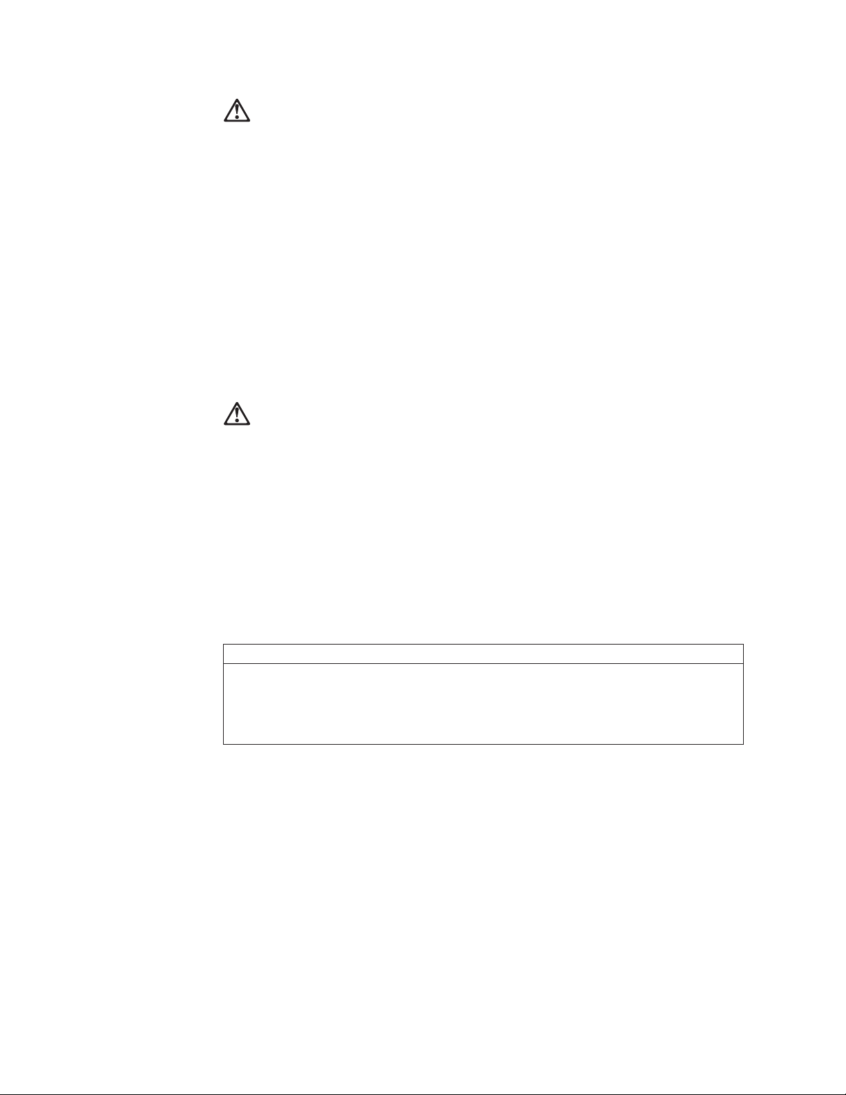
v
v
v
92
Achtung:
Eine verbrauchte Batterie nur durch eine Batterie mit der IBM Teilenummer
33F8354 oder durch eine vom Hersteller empfohlene Batterie ersetzen. Wenn Ihr
System ein Modul mit einer Lithium-Batterie enthält, ersetzen Sie es immer mit
dem selben Modultyp vom selben Hersteller.Die Batterie enthält Lithium und kann
bei unsachgemäßer Verwendung, Handhabung oder Entsorgung explodieren.
Die Batterie nicht
mit Wasser in Berührung bringen.
über 100 C erhitzen.
reparieren oder zerlegen.
Die örtlichen Bestimmungen für die Entsorgung von Sondermüll beachten.
Achtung:
Wenn ein CD-ROM-Laufwerk installiert ist, beachten Sie folgendes. Steuer- und
Einstellelemente sowie Verfahren nur entsprechend den Anweisungen im
vorliegenden Handbuch einsetzen. Andernfalls kann gefährliche Laserstrahlung
auftreten.
Das Entfernen der Abdeckungen des CD-ROM-Laufwerks kann zu gefährlicher
Laserstrahlung führen. Es befinden sich keine Teile innerhalb des
CD-ROM-Laufwerks, die vom Benutzer gewartet werden müssen. Die Verkleidung
des CD-ROM-Laufwerks nicht öffnen.
VORSICHT
Manche CD-ROM-Laufwerke enthalten eine eingebaute Laserdiode der Klasse 3A oder 3B.
Die nachfolgend aufgeführten Punkte beachten.
Laserstrahlung bei geöffneter Tür. Niemals direkt in den Laserstrahl sehen, nicht direkt mit
optischen Instrumenten betrachten und den Strahlungsbereich meiden.
Hardware Maintenance Manual
 Loading...