

Page 1

Hardware Maintenance Service
for Serv ice Level A
Machine Type 2284
Page 2

First Editio n (September, 2000)
The following paragraph does not apply to any state
or country where such provisions are inco ns i stent
with local law: INTERNATIONAL BUSINESS
MACHINES CORPORATION PROVIDES THIS
PUBLICATION “AS IS” WITHOUT WARRANTY OF
ANY KIND, EITHER EXPR ESSED OR IMPLIED,
INCLUDING, B UT NOT LIMITED T O, THE IM PLIED
WARRANTIES OF MERC HANTABILITY OR
FITNESS FO R A PARTICULAR PURPOSE.
References to IBM products, programs, or services
do not imply that IBM intends t o make them available
outside the United States. This publication could
include technical inaccuracies or typographical
errors. Changes are periodically made to the
information herein; these changes will be made in
later editions. IBM may m ake improvements and/or
changes in the product(s) and/or the program(s) at
any time. Address comment s about this publication to
IBM Corporation, Dep t . E23/962-2, 455 Park Place,
Lexington, KY 40511-1856, USA . Information you
supply may be used by IBM without obligation. For
copies of pub lica tions related to this product, call toll
free 1-800-IBM-7282 in the Continental U.S.A. In
Canada, call toll free 1- 8 00-465-7999.
© Copyright Internat i ona l B usi ne s s Machines
Corporation 2000.
All rights reserved.
Note to U.S. Governme n t Users - Documentation
related to restricted righ ts - Use , duplication or
disclosure is subject to restrictions set forth in GSA
ADP Schedul e Contra ct with IBM Corp.
Page 3

Contents
Contents ..............................................................iii
Notices ................................................................vii
Safety In forma t ion .. .. .. .. .. .. .... .. .. .. .. .. .... .. .. .. .. ..........viii
Laser Compliance Statement .............................xxxi
Trademarks ....................................................... xxxii
Preface ...... ............ .......... ............ .......... ........... xxxiii
General Information .............................................1
Introduction ............................................................2
Product Over vi ew ...... .............. ...............................3
Processor.........................................................3
Memory ............................................................3
External Po rts.......... .. .............. .. .. .....................4
Diskette Drive...................................................4
Hard Disk Drive .............. .. .. .. .. .. .. .. .. .. .. .. .. ..........4
DVD-ROM Drive...............................................5
Multimedia........................................................5
Power Managem ent.... .... .... .. .... .... .... .... .. .........5
Power Supply.... .. .... .... .. .... .. .... .... .. .... .. .............6
Internal Ca bling.. .... .... .... .... .. .... .... .... .... ............6
Monitor (Not included with some models) ........6
Keyboard..........................................................7
Mouse ..............................................................7
Hardware I n terf a ces ....... .. .. .. .. .. .. .. .. .. .. .. .. .. .. .. ..........8
CMOS Reset .... ...... ...... ...... ...... ...... ...... ................10
Power-On Pa ssword .. ........ ...... ........ ........ ............11
Flash (BIOS) Update Procedure ........ ........ ..........12
BIOS-contained Model Number and
Serial Number ......................................................13
BIOS Configurat ion/S etup Utility ........ ...... ...... ......14
Working with the Configuration/Setup
Utility Menu . .. ...... .... .... .... .... .... ...... .... .............14
Viewing Syst e m Information, and
Product Data ................. .. .............. .. ...............17
Devices and I/ O ports.... .. .... .. .. .... .. .. .... .. .........17
Startup Options ..............................................20
Date and Time.......... .. .... .. .. .. .. .. .. .. .... .. .. ..........21
Advanced Setup........... ...... ........ ...... ..............23
Power Managem en t Setup........ .... .. .... .... .......24
Specifications . .......... .......... .......... .......... .............. 29
Dimension (width x dep th x height)........... .....29
Weight............................................................29
Environment...................................................29
iii
Page 4

Power consump ti on . .... .. .... .... .... .... .... .. ...........29
Electrical input.......... .... .... .... .... .. .... .... ............29
Operating Requir ements . ........ ...... ...... ........ .........30
Check Procedur es ..... ........ ...... ........ ...... ............31
Introduction ..........................................................32
Start .....................................................................33
Index of Symptoms, Messages, Error Codes,
or Beeps ...............................................................38
Troubleshooting ...................................................54
Factory-Installed Storage Devices .................54
Factory-Installed Modem Card ...... ................ .......58
Audio (Not S u pported by Diagno sti c s Program) ..60
CD/DVD-ROM Drive ............................................63
Memory ................................................................65
Keyboard ....... .............. .............. .............. .............66
Mouse ..................................................................67
Power Supply ........... .. .... .... .. .... .. .... .... .. .... ............69
Monitor .................................................................72
Undetermined P rob lems ......... .. .... .... .. .... .... .........74
Diagnostic Aids ... ...... ...... ........ ...... ...... ...............77
Introduction ..........................................................78
Power-On Se lf Test ............ ........ ........ ...... ............79
Diagnostic Diskette ..............................................81
Using the Diagnostic Diskette .......................81
Using Diagnostic Program from
Recovery CD .. .. .. .... .. .. .. .. .. .... .. .. .. .. .. .... ...........82
Diagnostics Pr ogram Featu r es ........ .. .. .... ......83
Repair Information .............................................85
Removals and Replacements ............. .......... .......86
Handling E SD- S e nsi t ive Parts ................ .. .. .. .......87
Cover..............................................................90
Bay Panels........ ........ ........ ........ ........ .............92
Bay 1- 5.25-In. Bay
(Internal or E xt ernal Access).... .. .. .. ................93
Bay 3 - 3.5-In. Ba y
(Internal or E xt ernal Access).... .. .. .. ................94
Bay 4 - 3.5-In. Ba y
(External Acce ss for D i skette Drive ) ..............94
Front Panel........ .. .............. .. .. .............. ...........96
Power Supply.... .. .... .... .. .... .. .... .... .. .... .. ...........97
Adapter Ca rds ............................ .. ..................98
Memory(DIMM) ..............................................99
AMD K7 Du ron Processor... .. .. .............. .......100
iv
Page 5

System Backup Batte r y.. .. .. .... .. .. .. .... .. .. ........102
Indicator LED and Cable ............ .. .. .. .. .. ........103
System Board............ .. .. .... .. .. .. .. .. .. .. .............104
Parts/Test P oint Locations .... .... .. .... .... .. ..........107
Introduction ........................................................108
System Board Jump ers a n d Connectors ...........109
Power Supp ly Connec t ors and Voltages ...........111
Network Cards ...................................................113
Factory-Installed Modem Card Layout ...............114
Video Cards ....... .. .. .. .. .. .. .. .. .. .. .. .. .. .. .. .. .. .. ............115
Nvidia M64 w / T V Out, 32MB ............... .. ......115
Nvidia NV10 w/ TV Out, 32MB..... .. .. .. .. .. ......115
3.5-In. Hard Disk Drive Jumper Settings ............117
CD-ROM Drive ...................................................119
CD-ROM Drive Rear Panel Connectors
and Jumpers ......... .... .. .. .. .. .. .... .. .. .. .. .. ...........121
CD-ROM R/W Drive ...........................................122
CD-ROM R/W Drive Rear Panel
Connectors and Jumpers...... ........ ........ .......123
DVD-ROM Drive...........................................124
DVD-ROM Drive Rear Panel Connectors
and Jumpers ......... .... .. .. .. .. .. .... .. .. .. .. .. ...........125
DIMM C on figurations .. ...... .... ...... ...... ...... ...........126
System Board Conne ctor P in Signals ... .. .. .. .. .....127
Monitor Port Signals.....................................127
Serial Port Signals........................................127
Parallel Port Si gnals.......... .. .. .............. .........128
Mouse Port Signals............... .. .. .... .. .. .. .........128
Keyboard P ort Signals ..... .. .. .. .. .. .. .. .. .. .. ........128
Diskette Drive C a b le C o nne ctor Signals......129
IDE Ca ble C o nnector Signals .............. .. ......130
Safety Inspect ion Guide .. ...... ........ ........ ..........131
General Guidelines .............. .... ...... ...... ..............132
Parts Catalog ....................................................133
Abbreviations .....................................................134
System A ss embly ............ ...... ...... ...... ...... ..........135
Assembly 1: System Unit.............................135
Assembly 2: Diskette and Hard Drive ..........137
Assembly 3: CD/DVD-ROM Drive,
Adapter Ca rd and Speaker . .............. .. .. .......138
Assembly 4: Pow e r Cord........ .. .. .. .. .. .. .. ........141
Assembly 5: Keyboard and Mouse ..............142
v
Page 6

Appendix A. FRU Number List ........................143
Appendix B. Online Support Information ......147
Index .......... .............. .............. .............. ..............149
vi
Page 7

Notices
References in this publicatio n to IBM products,
programs, or servic e s do not imply th a t IBM intends
to mak e these availabl e in all countr ies in whic h IB
operates. An y ref erence to an IBM prod uct , program,
or service is n ot i ntend e d to stat e or imply that only
IBM's product, program , o r service may be used. Any
functionally equivalent p roduct, program, or service
that does not infringe any of IBM's intellectual
property rights, or other legally protectable rights,
may be used instead of the IBM product, program, or
service. Re fer ence s in t his publica tion t o IBM
products, programs, or services are purely hardwarerelated and do not c over ci rcumst an ces of soft ware
problems. Evaluation and verification of operation in
conjunction with other products, program, or services,
except those expressly designated by IBM are the
user's responsibility.
IBM may have patents or pending patent applications
covering subject matter in t his document. The
featuring of these patents, p ending or o th e rwise, in
this document does n ot g ive you any l i cense to these
patents. You can send license inquires, in writing, to
the IBM director of C om mercial Relat ion s, IBM
Corporation, P ur c hase, NY10577.
Voltage Supply Switch Settings
Your IBM Personal Computer might have voltage
switches, whi c h must b e set c orr ectly for your voltage
supply. If your monitor or system unit has a voltage
switch, complete these steps to make sure each
switch is set correctly:
1. Determine the co rre ct v ol t age swit c h s et t ing for
your ar ea:
Voltage Supply Range Voltage Switch Setting
100-127 V 115 V
200-240 V 230 V
2. Locate the voltage switch on the back of your
monitor or system unit. If the setting shown on the
switch is:
•
Correct: start setting up your IB M c om puter.
•
Incorrect: change the voltage switch setting.
Notices vii
Page 8

Safety Information
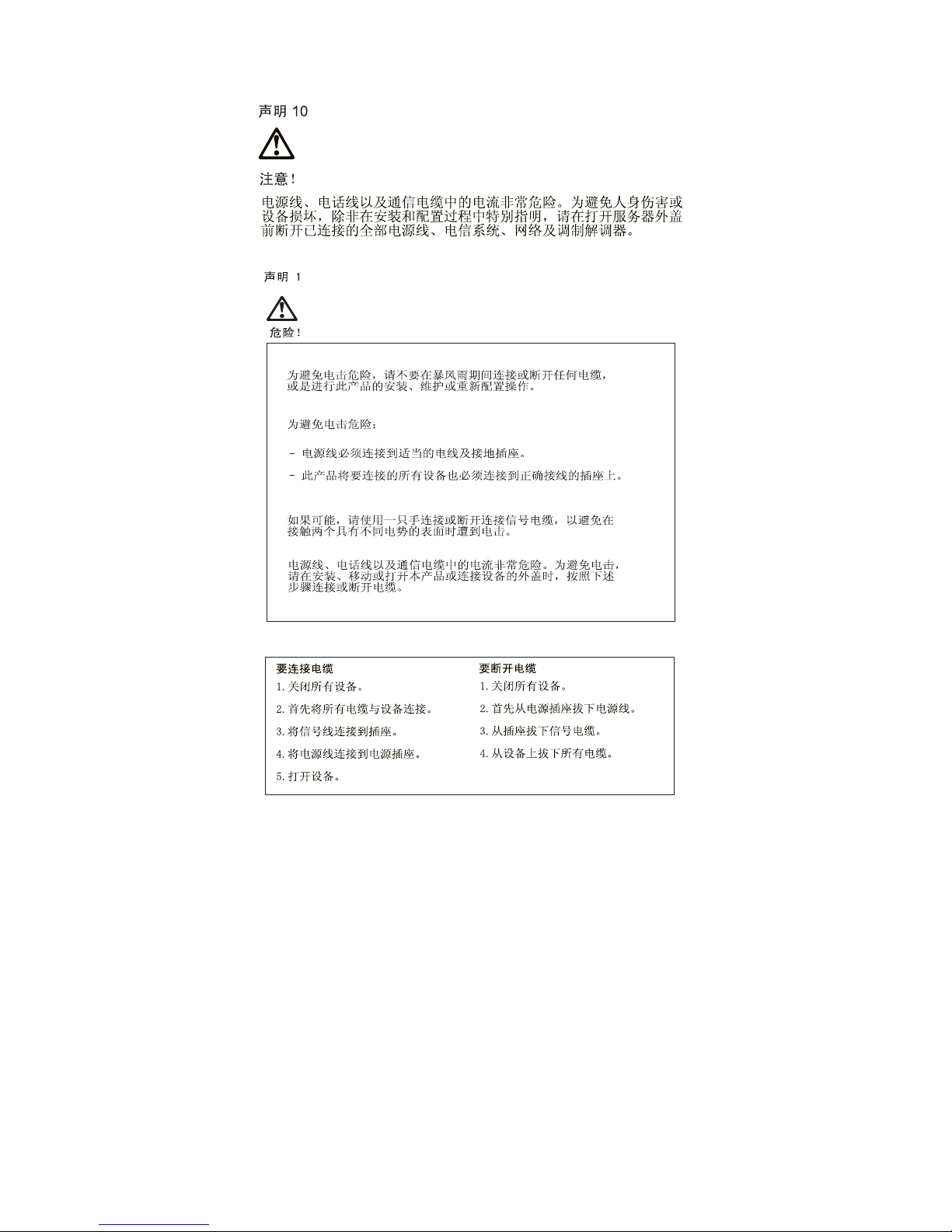
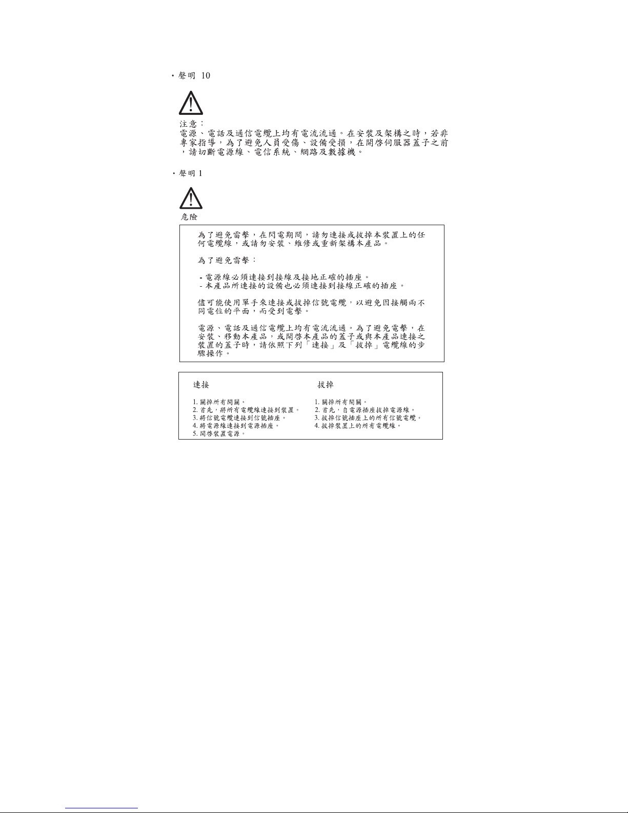
DANGER
To avoid a shoc k hazar d, do n ot connect or
disconnect any cable s or perform insta llation,
maintenance, or reconfiguration of this product during
an elec tr ic al storm.
To avoid shock hazard:
•
The power cor d m u s t be c on nected to a properly
wired and earthed receptacle.
•
Any equipm ent to which t his prod u ct will be
attached must also be conn ect ed to p ro perly wired
receptacles.
When possib l e , use one hand t o connect or
disconnect signal c a bles t o prevent a poss ible shock
from touching two surfaces with differe nt el ec trical
potentials.
Electrical c urr ent fr om power, telephone, and
communications cab les is haz ardou s. To avoid shock
hazard, co nnect and disconnect cables as described
following when installing, m ovin g, or o p ening covers
of this product or attached devices.
To Connect
1. Turn Everything OFF.
2. First, attach all cables to
devices.
3. Attach signal cables to
receptacles.
4. Attach power cord(s) to
outlet.
5. Turn device ON
To Disconnect
1. Turn Eve r y thi ng O FF.
2. First, remove power
cord(s) from outlet.
3. Remove signal cables
from receptacles.
4. Remove all cables from
devices.
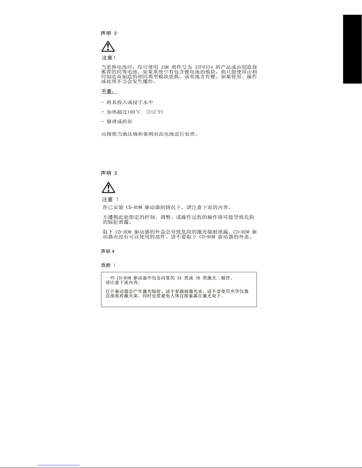
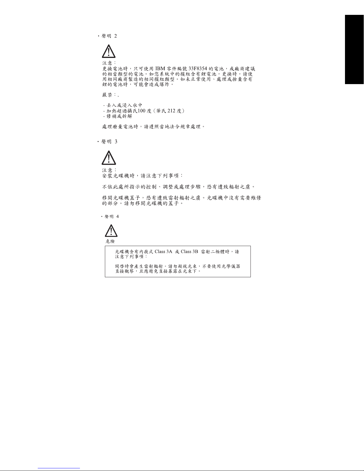
IMPORTANT:
When replacing the battery, use only IBM Part
Number 33F8354 or an equivalent type battery
recommended by the man ufacturer. If your
system has a module containing a lithium
battery, rep lace i t only wit h t he s ame module
type made by the same m an ufa cturer. The
viii
Page 9

battery contains lithium and can explode if not
properly used, handled, or disposed of.
Do not:
•
Throw or immers e into water
•
Heat to more than 100°C (212°F)
•
Repair or disassemble
Dispose th e battery as required by local ordinances
or regulations.
IMPORTANT:
When a CD-ROM drive is installed, note the following.
Use of con tr ols or adj ustme nts or per fo rm ance of
procedures other than those specified herein might
result in hazardous radiation exposure.
Removing th e c ove rs of th e CD - R OM drive could
result in exposure to hazardous laser radiation. There
are no servi ce ab le parts insi de th e CD-R OM drive.
Do not remove th e CD-ROM d r i ve c overs.
DANGER
Some CD-R OM drives contain an embedded Class
3A or Class 3B laser diode. Note the foll owing.
Laser radiation when open. Do not sta re into the
beam, do not view direc tly with opt ical ins truments,
and avoid direct exposure to the beam.
IMPORTANT:
Electrical c urr ent fr om power, telephone, and
communicat ion c ables ca n be ha zardous. To avoid
personal injury or equipmen t damage , disconnect the
attached power cords, telecommunications systems,
networks, and modems before you open the server
covers, unless instructed otherwise in the installation
and configuratio n procedures.
Notices ix
Page 10

PERIGO:
Para evitar choques elétricos, não conecte ou
desconecte nenhum cabo, nem efetue instalação,
manutenção ou reconfiguração deste produto
durante uma tempestade com raios.
Para evitar choques elétricos:
•
O cabo de alimentação deve ser conectado a um
receptáculo corretamente instalado e aterrado.
•
Todos o s e quip am e ntos aos quais este produto
será conectado devem também ser conectados a
receptáculos corret a m ente instalados.
Quando possível, utilize uma das mãos para
conectar ou desconectar cabos de sinal, para evitar
um possível choque ao tocar duas superfícies com
potenci ais el étricos difere nte s.
A corrente elétrica provenie nt e de cabos de
alimentação, de telefone e de comunicação é
perigosa. Para evitar choques elétricos, conecte e
desconecte os cabos conforme descrito a seguir, ao
instalar, movimentar ou abrir tampa s deste produto
ou de dispositivos conectados.
Para Conectar
1.DESLIGU E tudo.
2.Conecte primeiro todos
oscabos nosdispositivos.
3.Con ecte os cabos de sinal
nos receptáculos.
4.Conecte o(s) cabo(s) de
alimentação nas
tomadas.
5.LIGUE o dispositivo
x
Para D e sconec t ar
1.DESLIGUE tudo.
2.Rem ov a prim eiro o(s)
cabo(s) de alimentação
das tomadas.
3.Remova os cabos de sinal
dos receptáculos.
4.Rem ova to dos os cabos
dos dispositivos
Page 11

CUIDADO:
Ao substituir a bateria, utilize apenas o Número de
Peça IBM 33F8354 ou um tipo de bateria equivalente
recomendado pelo fabricante. Se seu sistema
possuir um módulo com uma bateria de lítio,
substitua-o apenas pelo mesmo tipo de módulo,
produzido pelo mesmo fabricante. A bateria contém
lítio e pode explodir se não for utilizada, manuseada
e descartada de f orma adequada.
Não:
•
Jogue ou coloque na água
•
Aqueça a mais de 100°C (212°F)
•
Conserte nem desmonte.
Descarte a bat eri a con forme requerido pelas
disposições e regulamen tações locais.
CUIDADO:
Quando uma unid ade de CD-ROM estiver instalada,
observe o seguinte.
A utilização de cont roles ou ajustes ou a execu ção de
procedimentos diferentes daqueles especificados
nesta publica ção pode resultar em exposi ção
perigosa à radiação.
A remoção das tampas da unidade de CD-ROM pode
resultar em exposição a radiação perigosa de laser.
Não existem peças que possa m ser consertadas no
interior da unidade de CD-ROM. Não remova as
tampas da unidade d e CD-ROM.
PERIGO:
Algumas un idades de CD-ROM contém um diodo de
laser da Classe 3A ou da Classe 3B . Observe o
seguinte.
Radiação de las er quand o aberto. Não olhe
diretamente para o feixe de laser, não olhe
Not ices xi
Page 12

direta mente com instrumentos óti cos, e evite
exposição direta ao raio.
CUIDADO:
A corrente elétrica provenie nt e de cabos de
alimentação, de telefone e de comunicação é
perigosa. Para evitar ferimentos pessoais ou danos
aos equipamentos, desconecte os cabos de
alimentação, sistemas de telecomunicação, redes e
modems antes de abrir as ta mpa s d o servidor, a
menos que receba outras instruções nos
procedimentos de instalação e configuração.
xii
Page 13
Notices xiii
Page 14
xiv
Page 15
Notices xv
Page 16
xvi
Page 17
PERIGO:
Pour éviter tout risque de choc électrique, ne
manipulez aucun câble et n'effect u ez aucune
opération d'installation, d'entretien ou de
reconfigurati on de ce produit au cours d'un orage.
Pour éviter tout risque de choc électrique :
•
Les cordons d'alimentation du présent produit et
de tous le s appareils qui lui sont conne ctés doivent
être branchés sur des socles de prise de courant
correctement câblés et mis à la te r re.
Afin d'éviter tout risque de choc électrique provenant
d'une différence de potentiel de terre, n'utilisez
qu'une mai n, l ors que cela es t possible , pour
connecter ou déconnect e r les c ordons d'interface.
Le courant électrique passant dans les câbles de
communication, ou les cordons téléphoniques et
d'alimentation peut être dangereux. Pour éviter tout
risque de c hoc électrique, l orsq ue v ou s installez ou
que vous déplacez le présent produit ou des
périphériques qui lui sont raccordés, reportez-vous
aux instructions ci-dessous pour connecter et
déconnecter les différents cordons.
Connexion
1. Mettez les unités hors
tension.
2. Comm encez par
brancher tous les
cordons sur les unités.
3. Br anchez les câbles
d'interface sur les prises.
4. Br anchez les cor dons
d'alimentation sur un
socle de prise de
courant.
5. Mettez les unités sous
tension.
Déconnexion
1. Met t ez l es u ni tés hors
tension.
2. Com me n ce z pa s
débrancher les cordons
alimentation des socles
de prise de courant.
3. Débranchez les câbles
d'interface des prises.
4. Débranchez t ous les
câbles des unités.
Notices xvi i
Page 18

ATTENTION:
Remplacez la pile usagée par une pile de référence
identique exclusivement - voir la référence IBM - ou
par une pile équivalente recomma n d ée par le
fabricant. Si votre système est doté d'un module
contenant une pile au lith ium, vo us devez le
remplacer uniquement par un module identique,
produit par le même fabricant. La pil e contient du
lithium et présente donc un risque d'ex plosion en cas
de mauvaise manipulation ou utilisation.
•
Ne la jetez pas à l'eau.
•
Ne l'exposez pas à une tempéra ture supérieure à
100°C.
•
Ne cherchez pas à la réparer ou à la démonter.
Pour la mise a u reb ut, report ez-vo u s à la
réglementation en vigueur.
ATTENTION:
Si une unité de CD-ROM est installée, prenez
connaissance des informations suivantes :
Pour éviter tout r is que d'exp osition au ra yon laser,
respectez les consignes de réglage et d'utilisation
des commandes, ainsi que les procédures décrites
dans le prés ent d o cument.
Pour éviter une expositi o n direct e au rayon laser,
n'ouvrez pas l'unité de CD-ROM. Vous ne pouvez
effectuer aucune opération de maintenance à
l'intérieur.
PERIGO:
Certaine s unités de CD-ROM contiennent une diode
laser de classe 3A ou 3B . Prenez conna issance des
infor m a tions sui vantes :
Rayonnement laser lorsque le carter est ouvert.
Évitez de regard er fixement le faisceau ou de
xviii
Page 19

l'observer à l'aide d'instruments optiques. Évitez une
exposition directe au rayon.
ATTENTION:
Le courant électriqu e ci rcu la n t dans les câbles de
communication et les cordons téléphoniques et
d'alimentation peut être dangereux. Pour votre
sécurité et celle de l'équipement, avant de retirer les
carters du serveur, mettez celui-c i hors t ension et
déconnectez ses cordons d'alimentation, ainsi que
les câbles qui le relient aux réseau x, aux systèmes
de télécommunication et aux modems (sauf
instr uct ion contraire mentionnée dans les procédures
d'installati on et de confi gu ration)
.
Notices xix
Page 20

VORSICHT:
Aus Siche rheitsgründen bei Gewitter an diese
Gerät keine Kabel anschließen oder lösen. Ferner
keine Installa tions-, W artungs- oder
Rekonfigurationsarbeiten durchführen.
Aus Siche rheitsgründen:
•
Gerät nur an eine Schutzkontaktsteckdose mit
ordnungsgemäß geerdetem Schutzkontakt
anschließen.
•
Alle an ges chl ossenen Geräte ebenfalls an
Schutzkontakts teckdo se n mit ordnung sgemäß
geerdetem Schutzkontakt anschließen.
Signal kabel möglichst einhändig anschließen oder
lösen, um einen Stromschlag durch Berühren von
Oberflächen mit unterschiedlichem elektrischem
Potential zu vermeiden.
Elektrisc he Sp ann u ngen von Netz-, Telefon- und
Datenübertra gu ng slei t unge n sin d ge fährlich. Um
einen Stromschlag z u v ermeiden, nur nach den
Anweisungen arbeiten, die für Installation, Transport
oder Öffnen von Gehäusen dieses Produkts oder
angeschlossenen Einheiten gelten.
Kabel anschließen
1.Alle Geräte ausschalten
und Netzstecker ziehen.
2.Zuerst alle Kabel an
Einheiten anschließen.
3.Signalkabel an
Anschlußbuchsen
anschließen.
4.Netzst ecker an Steckdose
anschließen.
5.Gerät ein schalten.
xx
Kabel lösen
1.Alle Geräte ausscha lten.
2.Zuerst Netzstecker von
Steckdose lösen.
3.Signalkabel von
Anschlußbuchs en lösen.
4.Alle Kabel von Einheiten
lösen.
Page 21

ACHTUNG:
Eine verbrau chte Ba t terie nur durch eine Batterie mit
der IBM Teilenummer 33F8354 oder durch eine vo
Hersteller emp f ohl ene Ba tter i e ersetzen. Wenn Ihr
System ein Modul m it einer Lith iu m-Batterie enthält,
ersetzen Sie es i mm er mit dem selben Modultyp vom
selben Hersteller. Die Batterie enthält Lithium und
kann bei unsach gemäßer Verwendung, Handhabung
oder Entso rgu ng exp lod ieren.
Die Batterie nicht
•
mit Wasser in Berührung bringen.
•
über 100 C er hitzen.
•
reparieren od e r zerlegen.
Die örtlichen Bestimmungen für die Entsorgung von
Sondermüll beachten.
ACHTUNG:
Wenn ein CD -ROM- La u f w er k installie rt is t, beachten
Sie folgend es. S teue r- und Einstellelemente sowie
Verfahren n u r entsp r ech e nd de n Anweisungen im
vorliegenden Handbuch ein setzen. Andernfalls kann
gefährliche Laserstr ahlu ng auftreten.
Das Entfernen der Abdeckungen des CD-ROMLaufwerks kann zu gefährlicher Laserstrahlung
führen. Es befinden sich keine Teile innerhalb des
CD-ROM-Laufwerks, d i e vo m Benutz er g ewartet
werden müssen. Die Verkleidung des CD-ROM-
Laufwerks nicht öffnen.
VORSICHT:
Manche CD-RO M-L aufw erke enthalten eine
eingebaute Laserdiode der Klasse 3A oder 3B. Die
nachfolgend aufgeführten Punkt e beachten.
Laserstr ah lu ng bei geöffneter Tür. Niemals di rekt in
den Laserstr a hl s ehen, nicht direkt mit optischen
Notices xxi
Page 22

Instrument en betrachten und den Strahlun gsbereich
meiden.
ACHTUNG:
An Netz-, Telefon- und Datenleitungen können
gefährliche elektrische Spannungen anliegen. Um
eine Gefährdung des Benutzers oder Beschädigung
des Geräts zu vermeiden, ist der Server
auszuschalten. Die Verbindung zu den
angeschlossenen Netzk abeln,
Telekommuni ka tio nss ystemen, Netz werken und
Modems ist vor dem Öffnen des Servergehäuses zu
unterbrechen (sofern in Installations- und
Konfigurations a n we isung en nicht anders angegeben)
PERICOLO:
Per evitare il perico lo di scosse elettriche duran te i
temporali, non collegare o scolleg a r e cavi, non
effettuare l'installazione, la manutenzione o la
riconfigurazione di questo prodotto.
Per evitare il pericolo di scosse elettriche:
•
collegare i l c avo di alime n tazione ad una presa
elettrica correttamente cabl ata e munita di terra di
sicurezza;
•
collegare qualsia si apparecchia tura collegata a
questo prodotto ad una presa elettrica
correttam ent e ca blata e munita di terra di
sicurezza.
Quando possibile, collegare o scollegare i cavi di
segnale con una sola mano per evitare il rischio di
scosse derivan ti dal conta tto co n due su perfici a
diverso potenziale elettrico.
La corr ente elettrica ci rc ola nte nei cavi di
alimentazione, del telefono e di segnale è pericolosa.
Per evitare sc osse elettriche , collegare e s c ollegare
xxii
Page 23
icavi come des c ritto quando si effettuano
l'installazione, la rimozione o l'apertura dei coperchi
di questo prodotto o durante il collegamento delle
unità.
Per collegare
1.SPEGNE RE tutti i
dispositivi.
2.Collegare prima tutti I cavi
alle unità.
3.Col le gare i c av i di se gn al e
alle prese.
4.Collegare il(i) cavo(i) di
alimentazione alla presa
elettrica.
5.ACCENDERE le unità.
Per scollegare
1.SPEGNE RE tu tti i
dispositivi.
2.Rimuovere prima il(i)
cavo(i) di alimentazione
dalla presa elettrica.
3.Rimuovere i cavi di
segnale dalle prese.
4.Rimuovere tutti i cavi dalle
unità.
ATTENZIONE:
Quando si sostituisce la batteria, utilizzare solo una
batteria IBM o batterie d ell o stesso tipo o di tipo
equivalente consig lia te d al p rodutto re . Se il sistema
di cui si dispone è provvisto di un modulo contenente
una batteria al litio, sostituire tale batteria solo con un
tipo di modulo uguale a quello fornito dal produttore.
La batteria con tiene litio e può esplod er e se utilizzata,
maneggiata o smaltita i mpro priamente.
Evitare di:
•
Gettarla o immergerla in acqua
•
Riscaldarla ad una temperatura superiore ai 100°C
•
Cercare di ripararla o smaltirla
Smaltire secondo la normativa in vigore (D.Lgs 22 del
5/2/97) e succ e s s iv e dispos iz ioni n az ionali e locali.
Notices xxiii
Page 24

ATTENZIONE:
Quando è installata un'unità CD- ROM, notare quanto
segue:
L'utilizzo di controlli, regolazioni o l' ese cuzione di
procedure non descri t ti n e l presente manuale
possono provocare l 'esp osiz io ne a radiazioni
pericolose.
L'apertura di un'unità CD-ROM pu ò determinare
l'esposizione a radiazioni laser pericolose. All'interno
dell'unità CD-ROM non vi sono parti su cui effettuare
l'assistenza tecni ca. Non rimuovere i coperchi
dell'unità CD-ROM.
PERICOLO:
Alc une un it à CD- ROM contengono all'interno un
diodo laser di Classe 3 A o Classe 3B. Prestare
attenzione a quanto segue:
Aprendo l' un ità vengono emesse radiazioni laser.
Non fissare il fascio, non guardarlo direttamente con
strumenti otti ci ed evitare l' esp osiz io ne diretta al
fascio.
ATTENZIONE:
La corrente circolante nei cavi di alimentazione, del
telefono e di segnale è pericolosa. Per evitare
situazioni pericolose per le persone o
danneggiamenti all'apparecchiatura, scollegare i cavi
di alimentazione, i sistemi di telecomunicazioni, le reti
e ed i modem prima di aprire i coperchi del se rvente
se non diversamente indicato nelle procedure di
installazione e configurazione.
xxiv
Page 25
Notices xxv
Page 26
xxvi
Page 27
PELIGRO:
Para evitar una posible descarga eléctrica, no
conecte ni desco necte lo s cabl es ni lleve a cabo
ninguna operación de instalación, de mantenimiento
o de reconfiguración de este producto durante una
torm enta eléctrica.
Para evitar un a pos ible descarga:
•
El cable de alimentación debe conectarse a un
receptáculo con una instalación eléctrica correcta
y con toma de t i erra.
•
Los aparatos a los q u e s e conecte es te producto
también deben estar conectados a re ceptáculos
con la debida instalación eléctrica.
Cuando sea posible , utilice un a sola mano para
conectar o desconect ar los cables de señal a fin de
evitar una posible descarga al tocar dos superficies
con dis tinto potencial eléctrico.
La corr ie nte eléctrica de los cables de
comuni ca ci on es , te l éfono y alimentación puede
resultar p eligrosa. Para evitar u na p osi ble descarga,
siga las indicaciones de conexión y desconexión de
los cables siempre que tenga q ue instalar, mover o
abrir las cubiertas de este producto o de los
dispositivos acoplados.
Instr u cciones d e
conexión
1.Ap ague to do s los
componentes (OFF).
2.En primer lugar, conecte
todos los cables a los
dispositivos.
3.Conecte los cables de
señal a los receptáculos.
4.Conecte los cables de
alimentación a las tomas.
5.En cienda el di sposit iv o
(ON).
Inst r ucciones d e
desconexión
1.Encienda todos los
componentes (ON).
2.En primer lu gar, r etire los
cables de alimentación de
las tomas.
3.Retire los cables de señal
de los receptáculos.
4.Retire todos los cables de
los dispositivos.
Notices xxvii
Page 28

IMPORTANT:
Al cambiar la bater ía, utilice únicamente la batería
IBM Núme ro de pieza 33F8354 o un tipo de batería
equivalente recomendado por el fabricante. Si el
sistema tiene un módulo que contiene una batería de
litio, sustitúyalo únicamente por el mismo tipo de
módulo del mismo fabric ante. La batería contiene litio
y puede exp lot ar si no se u tiliza, manipula o desecha
correctamente.
Lo que no debe hacer
•
Tirar o sumergir el producto en agua.
•
Exponer el producto a una temperatura superior a
100°C.
•
Reparar o desmontar el producto.
Cuando quiera desechar la batería, siga las
disposiciones y reglamentaciones locales.
IMPORTANT:
Cuando instale una unidad de CD-ROM, tenga en
cuenta la siguiente información.
Si se llevan a cabo co ntr ol es o ajust e s o se utilizan
métodos que no se atengan a lo aquí especificado,
se puede producir una exposición peligrosa a las
radiaciones.
Si se retiran las c ubie rtas de la un i dad de CD-ROM,
se puede producir una pe ligro sa exposición a
radiaciones de láser. Dentro de la unidad de CD-
ROM no exis t en pi e za s re pa r abl es . No re tir e las
cubiertas de la unidad de CD-ROM.
PELIGRO:
Algunas unidades de CD-ROM tienen incorporado un
diodo de láser de Clase 3A o de Clase 3B Tenga en
cuenta la siguiente información.
xxviii
Page 29

Cuando la unidad e stá abierta se generan emisiones
de rayos láser. No dirija la mirada al haz, no lo
observe directamente con instrumentos ópticos y
evite la exposición directa.
IMPORTANT:
La corr ie nte eléctrica de los cables de
comunicac io nes , de teléfono y de alimentación puede
resultar peligrosa. Para evitar posibles lesiones o
daños del aparato, desconecte los cables de
alimentación, los sistemas d e teleco m unicaciones,
las redes y los módems antes de abrir las cubiertas
del servid or, salvo que se in dique lo co ntrario en las
instr ucciones de las operaciones de instala ción y
configuración.
Notices xxix
Page 30

Laser Compliance Statement
The CD-ROM drive in the computer is a laser
product. Th e C D- ROM d rive's classification label
(sample shown below) is located on the drive.
CLA SS 1 LASER PRODUCT
APP A R E I L A LA SER CLASSE 1
LAS E R K LASSE 1
LUOKAN 1 LASERLAITE
PRODUIT LASE
CATEGORIE 1
The CD-ROM drive is certified in the U.S. t o conform
to the requirements of the Department of Health and
Human Services 21 Code of Federal Regulations
(DHHS 21 CFR) Subchapter J for Class 1 laser
products.
In other c ount ries, the drive is ce rtified t o conform to
the requirement s of EN60825.
Class 1 laser products are not considered to be
hazardous. T h e C D- ROM drive has an internal Class
1, 0.5-milliwatt, aluminum gallium-arsenide laser that
operates at a wavelength of 760 to 810 manometers.
The design of t he laser system and the CD-ROM
drive ensur es th at the r e is n o exposur e to laser
radiation above a Class 1 level during n o r mal
operation, us er maintenan ce, or servicing conditions.
xxx
Page 31

Trademarks
The following are trademarks of the IB M Corporation
in the United State s or other countries or both:
AT
HelpCenter
IBM
Operating System/2
OS/2
Personal System/2
PS/1
PS/2
Intel, Pentium, MMX, EtherExpress, and LANDesk
are trademar ks or re g istered tradema rks of Intel
Corporation.
Microsoft, MS-DOS, Windows, and Windows NT are
trademarks or reg istered tra dem arks of Microsoft
Corporation.
Other company, p roduct, and serv i c e n ames may be
trademarks or service marks of others.
Notices xx x i
Page 32

Preface
This manual contains service information for the
Service Level A (SL-A)
Computer, worldwide. T his manual is intended to be
used as a stand-a lone d o cume n t to service m achine
type 2284 products. It is divided into the following
chapters:
Notices
notices required to service this computer.
General Information
this manual.
Check Procedu res
instructions that aid in locating the failing Field
Replaceable Un it (FRU).
Diagnostic Aids
tools for iso lati n g failures.
Repa ir in g Informat io n
descriptions to disassemble and reassemble the
computer.
contai ns im portant safe ty infor mation and
explains how to use the diagnostics
model of the IBM Personal
contains a brief description of
provides step-by-step
contains illustrations and
2284
Parts/Test Point Locations
descriptions of the loca t io ns of the major parts,
jumpers, and connectors.
Safety Inspe ct i on Gu ide
inspecting a machine for safety problems before
putting the ma c hine u n der a Maintenance
Agreement.
Parts Catal o g
and part numbers for individual FRUs.
Appendix A, FRU Number Index
numbers listed in numerical order.
contains descripti on s, i llus tr ations,
contains illustrations and
contains information about
contains part
xxxii
Page 33

Notices xxx i i i
Page 34

xxxiv
Page 35

General Information
Introduction ............................................................2
Product Over vi ew ...... .............. ...............................3
Processor.........................................................3
Memory ............................................................3
External Po rts.......... .. .............. .. .. .....................4
Diskette Drive...................................................4
Hard Disk Drive .............. .. .. .. .. .. .. .. .. .. .. .. .. ..........4
DVD-ROM Drive...............................................5
Multimedia........................................................5
Power Managem ent.... .... .... .. .... .... .... .... .. .........5
Power Supply.... .. .... .... .. .... .. .... .... .. .... .. .............6
Internal Ca bling.. .... .... .... .... .. .... .... .... .... ............6
Monitor (Not included with some models) ........6
Keyboard..........................................................7
Mouse ..............................................................7
Hardware I n terf a ces ....... .. .. .. .. .. .. .. .. .. .. .. .. .. .. .. ..........8
CMOS Reset .... ...... ...... ...... ...... ...... ...... ................10
Power-On Pa ssword .. ........ ...... ........ ........ ............11
Flash (BIOS) Update Procedure ........ ........ ..........12
BIOS-contained Model Number and
Serial Number ......................................................13
BIOS Configurat ion/S etup Utility ........ ...... ...... ......14
Working with the Configuration/Setup
Utility Menu . .. ...... .... .... .... .... .... ...... .... .............14
Viewing Syst e m Information, and
Product Data ................. .. .............. .. ...............17
Devices and I/ O ports.... .. .... .. .. .... .. .. .... .. .........17
Startup Options ..............................................20
Date and Time.......... .. .... .. .. .. .. .. .. .. .... .. .. ..........21
Advanced Setup........... ...... ........ ...... ..............23
Power Managem en t Setup........ .... .. .... .... .......24
Specifications . .......... .......... .......... .......... .............. 29
Dimension (width x dep th x height)........... .....29
Weight............................................................29
Environment...................................................29
Power consump ti on . .... .. .... .... .... .... .... .. ...........29
Electrical input.......... .... .... .... .... .. .... .... ............29
Operating Requir ements . ........ ...... ...... ........ .........30
General Information 1
Page 36

Introduction
This chapter gives a general overview of the Personal
Computer Type 2284, describes the standard and
optional features, and details its functional and
environmental specifications.
2 IBM Desktop System HMM
Page 37

Product Overview
Personal Computer T yp e 2284 has three PCI slots
and supports the A M D K7 D uro n pro cessor family
with Soc k et A processor package type.
The Personal Computer Type 2284 supports
Accele rated Graphi cs Port (AGP) 2X / 4X, which
allows installed sys tem memory to be use d as texture
memory, yielding a huge texture fo otprint to enhance
3D graphica l display perfor mance.
Listed below are 2284 system features:
Processor
•
Socket A connector.
•
Detachable CPU fan sink .
•
128 KB of on-chip level one (L 1 ) cache
•
64 KB level two (L2) cache support for Duron
•
AMD K7 processor; 200MHz fro nt s ide bus, 600/
700MHz, 0.18 M icrons, with 3DNow!
™
technology
•
Multiple parallel x86 instruction decoders
Memory
•
168-pin Sy n chr ono u s Dynamic Random Access
Memory (SDRAM), Dual in-line Memory Module
(DIMM) sockets.
- 3 memory sockets.
- 8MB, 16M B, 32 MB, 64MB , 12 8MB and 256MB
DIMM.
- PC-100/ 133 (8-128 M-bit, ECC , 133MHz,
3.3volt) DIMMs with gold contacts
- Maximum memory is 768MB
General Information 3
Page 38

External Port
•
2x/4x AGP v id e o card (15-pin V G A connector)
•
Multi-Mode Para llel port (25-pin D-ty pe c onnector)
•
Serial port (9-pin D-su b connecto r). 2284 has one
serial ports, serial port 1
•
Keyboard and mou se port
•
Four USB ports (2 on port bracket, the other 2 on
the front panel)
•
Game/MIDI port (15-pin D-sub c onnector)
•
Microphone-in jack
•
Speaker-ou t jack
•
Line-in jack
•
Telepho ne li n e-o ut c on ne ct o r (modem adapter
card avai lable)
•
Telepho ne li ne- i n connector (modem adapter card
available)
•
RJ-45 conn ect or (adapter card available)
Diskette Drive
•
3.5 “ drive for 2.88MB, 1.44MB o r 720KB diskette
•
5.25” drive for 1.2MB or 360KB diskette
•
Support 3-mode drive
Hard Disk Drive
•
3.5-in., 1-in. height IDE drive. (3.5-in may be in
acoustic mounting bracket), and 7200rpm.
•
128 KB “look-ahead” cache memory inside the
hard disk drive.
•
Average and minimum 12 ms seek time, access
time varies for the hard disk drive and the hard
disk drive manufacturer.
4 IBM Desktop System HMM
Page 39

DVD-ROM Drive
•
5.25-in. hig h-performance, 8X /40X DVD-ROM
IDE/AT drive.
•
Read data an d audi o play from standard, mini
DVD-ROM and a u di o compact discs ( audio CDs).
DVD media supported on DVD models.
Multimedia
•
A pair of ext erna l ac tive speakers w i th a power
adapter o r a pair of pa s s i ve s peakers.
•
Noise cance li ng microphone available.
Power Management
•
Support both ACPI (Advanced Configuration and
Power Interface) and l egacy (A P M) power
management.
•
ACPI v1.0 and APM v1.2 compliant
•
CPU cl ock thr ot tl i ng and clock stop control for
complete ACPI S1 and S 5 stat e support
•
PCI bus clock run, Po w e r Management enable
(PME) co ntrol, PCI/CPU color gen erator stop
control.
•
Power-on Switch m ust s uppor t So ft-O f f and
Full-Off.
- Touch for 1 s e con d or l ess to put system on
Suspend state.
- Touch and hold for 4 seconds to put system on
Full-Off state ( P ower Supply standby r emains).
•
System enters standby mode if any of following
conditions are met:
- Execu te s ta ndby fro m Windows 9 8 Start menu
- Press system power button if it sets to act as
standby f unction
- System is idle and the standby timer set in the
Windows 98 Power Management Property
elapses
•
8 bytes of BIOS scratch register
General Information 5
Page 40

Power Su p ply
•
PC-98 compatib le 145W ATX power supply
•
Switchable high/low voltage selection
Internal C ab l ing
•
Two 40-pin ribbon cables for hard disk drives and
CD/DVD-ROM drive.
•
One 34-pin ri bbon cab l e for AT diskette drive.
•
One 4-pin (2-wire ) cabl e f or ha rd disk drive
ligh t -em it ti ng di ode (L ED ).
•
One 3-pin (3-wire ) cabl e f o r power l ight -emitting
diode (LED).
•
One 2-pin (2-wire ) cabl e f o r power switch.
Monitor (Not included with some models)
•
Super Video Graphics Array (SVGA) monitor.
•
VESA power savin g mo de compliant.
•
Connector for a detachable grounded 3-wire
power cord
•
1.8-m (5.8 -f t.) signal cable attached
•
Auto-sensi ng power inp u t for 100 Vac to 240 Vac
•
15" (13.7" vi ew ab l e i mage size) monitor
- 0.28-mm dot pitc h
- Autom atic scanning horizo nta l frequencies from
30 KHz to 54 KHz or 30 KHz to 69 KHz
(for Japan)
- Vertical frequencies between 50 Hz and 120 Hz.
- DDC2A/ B o r DDC1/ 2 B + sup port ( f o r Japan)
- OSD (On-Screen Display) menu (for Japan)
•
17" (15.7" vi ew ab l e i mage size) monitor
- 0.28-mm or 0.27-mm dot pitch (for Japan)
- Autom atic scanning horizo nta l frequencies from
30 KHz to 69 KHz or 30 KHz to 72 KHz
(for Japan)
- Vertical frequencies between 50 Hz and 120 Hz.
- DDC1/2B+ support and OSD (On-Screen
Display) menu
6 IBM Desktop System HMM
Page 41

Keyboard
•
104-key, rubber dome Rapid Access™II keyboard
with 1.8- m (5. 8- ft . ) cable
Mouse
•
4 Button PS/2 Sleek or ScrollPoint™II mouse with
1.8-m (5.8-ft.) cable
General Information 7
Page 42

Hardwar e Interfaces
The following peripheral interfaces for adapters,
options, and dri v e s a re su p ported in the system unit.
Item Interface
Expansion slot for
I/O adapter cards
Hard disk drives Four PCI local bus Enhanced IDE
DVD-ROM drive 5.25- in. high-p erformance , 8X /40X
Diske tte drive AT diske tte interface
Video Physical interface is compatible with
Three PCI (Peripheral Component
Interconnect) v2.2 compatible
expansion slots that operates at 33
MHz bus speed.
v1.0 co mpatib le hard di sk dr i ve
inte r faces that support :
- PIO mo de up to 6 mode
- DMA 32-bit access
- Ultra 33/66 Synchronous DMA (3 3/
66M bytes/sec).
DVD-ROM IDE/AT drive.
Support Bootable CD-ROM Format
specification version 1.0.
Compliant to Audio-CD, Video-CD,
CD-ROM/XA, Karaoke-CD, and
Photo-CD (both single and multi
session) format.
the IBM Personal Sy ste m/ 2 ( PS/ 2 )
VGA inte rface .
Support Accelerated Graphics Port
(AGP)
Modem One 56.6 Kbps PCI modem adapter
Audio Compatible to AC99
Poin ting device IBM PS /2-compatib le mouse
Keyboard device IBM PS/2-compatible keyboard
Serial port Support one high speed NS 16C550
8 IBM Desktop System HMM
card with data/fax/voice or non-voice
features.
compatible UART s with send/rec eive
16 bytes FIFOs
RS232D electrical inte r face
compliant
Page 43

Item Interface
Parallel port Supports SPP (IBM PC/XT, PC/AT,
PS/2) compatible, EPP (IEEE 1284
compliance), ECP (IEEE 1284
compliance) interface.
IEEE 1284 compliant
Game port Game port interface for joystick. I t
also supports MIDI.
USB Supports Universal UHCI
Specification for USB 1.1
General Information 9
Page 44

CMOS Reset
This system does not deny access to Configuration/
Setup Utility, if Administrative Pas swo rd is not set.
Execute “Load BIOS Default Settings” in BIOS
Configuration /S etup Ut ilit y to cle a r the corrupted
CMOS data. See “Loadin g Def a u l t Set t ings” on page
16.
10 IBM Desktop System HMM
Page 45

Power-On Password
A power- on password denies access to the system by
an unauthorized user when the system i s powered
on. When a power-on password is active, the
password p ro mpt appe ars on the sc re en each time
the system is powered on. The system starts after the
proper password is enter ed. See “Power-On
password” on page 21 f or more information about
how to change, remove and se t password in
Configuration /S etup Ut ility.
In some cas es, y o u might be required to service a
system with an active and unknown power-on
password. To cl ear a pas s word from the system,
follow these steps .
1. Turn off system unit.
2. Unplug pow er cable from the electrical outlet.
IMPORTANT:
power cord p lug ge d into the electrical outlet.
The power supply maintai n s +5 V d c of standby
power wh e n the po w e r cord is plugged.
System damage might result if the p ower cord
is not u np l ugged durin g jumper setting.
3. Set JP14 to 2-3 p osition to clear BIOS setting as
original manufacture setting. See “System Board
Jumpers and Connectors” on page 109.
4. Set JP7 back to the 1-2 position to enable
password check process. See “Sys tem B oard
Jumpers and Connectors” on page 109.
IMPORTANT:
must enter a pass w o rd in the Configuration/Setup
Utility. If Enhanced Security is enabled and the
password is forgotten, the system board must be
replaced.
Do not attempt these steps with the
To reinstall the password, the user
General Information 11
Page 46

Flash ( BIOS) Update Procedure
NOTE:
1. Prepare a bootable DOS diskette with
NOTE:
2. Insert the diske tte and boot from drive A.
WARNING:
3. At the DOS prompt, type
4. The program updates the BIOS automatically.
IMPORTANT:
WARNING:
The flash update procedure does not change
the model number and serial number
information in BIOS.
AWDFLASH.EXE, and one XXXXXXX.BIN files
The AWDFLASH.EXE ar e flash utility
programs. The one VXXYYZZ.RN file has the
BIOS checksum information. The
XXXXXXX.BIN is BIOS source code binary file.
Do not boot with any memor y related
driver such as HIMEM.S YS, EMS.SYS....
A:> AWDAFLASH
XXXXXXX .BIN /PY/SN/CD/CP
Verify the BIOS checksum value shown
on screen is the same a s the one in
VXXYYZZ.RN file.
Do not turn off the system power while the
BIOS is programmin g, or the flash ROM will be
destroyed.
then press
Enter
.
5. Power off system after the BIOS is completely
updated.
12 IBM Desktop System HMM
Page 47

BIOS-contained Model Number and
Serial Number
The model nu mbe r an d serial number information is
stored in BIOS ROM and displayed in the “Product
Data” of Configuration/Setup Utility main menu. If a
service repair is completed by replacing a new
system board or a new BIOS ROM, then you are
required to input the original system's model number
and serial number into the new BIOS ROM.
Follow these s teps to input the model number and
seri a l number to BIO S:
1. Prepare a diskette with DMICFG.EXE file.
2. At the DOS prompt, type
3. When update sys t em pr oduct name, at the DOS
prompt type
[String]
For example:
[String] : Type 2284
type
2174”
NOTE:
4. When update system serial number, at the DOS
NOTE:
5. Enter BIOS setting to di s pla y a n d verify your input
.
You can type a maximum of 32 chara ct ers. If
you have a string with spaces, type
the string.
prompt typ e
Enter the serial number and press
continue. You ca n typ e a maximum of 32
characters (without spaces).
product number and seri al number information.
A:> D M ICF G.EXE/ type 01 05
.
A:>DMICFG.EXE/ t y pe 01 05 “Type
A:>DMICFG.EXE/ type 01 07 [String]
A:>DMICFG.exe
“ “
Enter
.
to quote
to
.
General Information 13
Page 48

BIOS Configuratio n/Setup Utilit y
The Conf iguration/Setup Ut ility lets you review and
change important information about the computer and
its hardware.
Working with the Configuration/Setup
Utility Menu
Sta r ti ng th e Confi gu r ation /S etup Uti lity
Follow these steps to enter Setup when the computer
is off:
1. Turn on your monitor.
2. Press and hold F1.
3. Turn on the system unit.
If you have prev iousl y set a passwo r d , you are
prompted to type in the password after you press the
F1
key. Refer to the Configuration/Setup Utility Main
Menu bel ow.
Configuration/Setup Utility
Select Options:
•
System Summary
•
Product Data
•
Device s and I/O Ports
•
Start Options
•
Date and Time
•
System Security
•
Advanced Setup
•
Power Management Setup
Save & Ex it Setup
Load Default Se ttin gs
Exit Without Sa ving
↓↓↓↓↑↑↑↑Move Enter:Select F1:Help
F10:Save ESC:Exit
14 IBM Desktop System HMM
Page 49

The following table lis ts sp ecifi c keys on the keyboard
that will help y o u move through the Configuration/
Setup Utility Menus:
Keys Function
Down- or uparrow key
Left- or rightarrow key
F1 P ress this key if you want help for a
Esc After vi ewi ng or maki ng chan ge s to
Enter Press this key to choose a
F10 Press this key if you wa nt to save
F7 Press this key if you wa nt to load
Use these arrow keys to highlight
an option on the menu. (Press the
Enter key to choose the option.)
Use these arrow keys to make a
selection and change an option's
setting. On some menus, you can
use these keys to move from one
field to an ot her.
selected menu option.
the settings on a menu, press this
key t o exit the menu.
highlighted option fro m a men u
the current settings for a line
the factory default settings from the
selected brackets.
F5 P re ss this key if y ou wan t to re sto re
item previo us setting
Changing P arameter Setting s
In the Configuration/Set up Util i ty M enus, the
configuration information that you can change is
enclosed in brackets like these: [ ]. You cannot
change any information that is not enclosed in
brackets. Use the up- or down- arrow keys to
highlight opti o ns then press
When changi ng the setting of a particular parameter,
highlight th e setting t hen us e the left- or right- arrow
key to ch ange the setting. Refer to the Configuration/
Setup Utilit y he lp for details on the configurable
parameters in each menu.
Enter
to display a menu.
General Information 15
Page 50

Save & Exit Settings
After changing any parame te r in t h e S etup
Configuration se tt ing , ret urn to Configu ratio n/Setup
Utility main menu and sel e c t Save & Exit Setup to
save all the settings you have changed. Then, exit the
Configuration/S etup Ut ilit y menu.
Loading D e fa ult Settings
The computer is already configured for use. The
original configuration settings , also called factory or
default settings, ar e st ored in the C MOS. Setup
includes an option Load Default Settings that lets you
reload the original configuration at any time.
To load the de faul t settings, follow these steps:
1. Use down-arrow key to select load default settings.
A dialog box appears confirming if you want to
load the default settings.
2. Use the l ef t -a rrow k ey to select Yes, then p r ess
Enter
.
3. Press
A dialog box appears confirming if you want to
save the setting s (in this c ase, the default settings
that you reloaded).
4. Use the l ef t -a rrow k ey to select Yes, then p r ess
Enter
Utility.
You must load the Setup default settings in the
following instances:
•
When you replace the sys tem battery.
•
When you customiz e the sy st em c onfiguration
settings and some resource assignments conflict
causing t he compu ter to sto p responding.
Esc
to exit Setup.
to save the changes in Configuration/Setup
16 IBM Desktop System HMM
Page 51

Exiting Without Saving
Press
finished viewing settings and making changes. Fro
this locat ion, y o u c an ex it Set up but w itho u t saving
your changes.
Esc
to return to the Main Menu when you have
Viewin g Sy st em Inf orm at io n , and
Product Data
To vie w g ene r al har d ware information about your
computer, select the Sy stem Summary option fro
the Configuration/Setup Utility main menu. The items
displayed in the System Summary menu are not
configurable.
Setup automatically updates this menu when you do
either of the fo l l owing:
•
Add or change hardware on your computer
•
Make chang es to othe r menus in Setup and save
those changes
To view the computer infor mation suc h as the
machine type/model, flash EEPROM revision level,
system serial number, BIOS version, BIOS date, and
BIOS mode, s ele ct t he Product D ata option from the
Configuration/S etup Ut ilit y main men u. L i ke in the
System Summary menu, the items d ispla y ed are not
configurable.
Devices and I/O ports
If you install USB devices, video, IDE drives, audio, or
network drive, BIOS a uto-detects the presence of
these de vices. Enter Configuration/Setup Utility to
identify or verify the type of drive in stal led in the
computer.
Diskette D rive A
This option displays the si z e and storage capacity of
the currentl y installed diskette drive . The default is
1.44 MB, 3.5 in..
Diskette D rive B
This option displays the si z e and storage capacity of
the currently installed diske tte driv e. Empty drive
bays are indicated with a “None” default setting.
General Information 17
Page 52

Serial Port Setup
Onboard Serial Port 1
It comes with one 9-pin s er ial po rts. This parameter
will be al lowed to set Auto, Disab l ed, or the base
address such as 3F8/IRQ4, 2F8/IRQ3, 3E8/IRQ4, or
2E8/IRQ3 f or seri al port . The defau lt i s s et to Auto.
Parallel Port Setup
Onboard P aral lel Port
Your co mpu ter c o m e s wi t h one para ll el p ort. This
parameter shows the base address to activate the
parallel port. The default base address is 378h and
the default IRQ is 7.
Onboard Parallel Mode
There are four sel ec tion for this param eter Normal,
EPP, ECP, ECP/EPP. The default setting is Normal.
ECP Mode Use DMA
When Onboard parallel Mode is set to ECP or ECP/
EPP, this paramete r be com es configurable.
Otherwise, it will be unchangeable and the default
setting is 3.
Parallel Port EPP Type
When Onboard parallel Mode is set to EPP or ECP/
EPP, this paramete r be com es configurable.
Otherwise, it will be unchangeable and the default
setting is EPP1.9.
USB Setup
Onboard USB
The item Universal Seri al Bus (USB) pa rameter is
allowed to set as Enabled and Disabled . The default
setting is Enabled.
USB Keyboard Support
The default setting is set to Disabled while the
parameter Onboard USB is Enabled. If Onboard
USB is set to Disabled , this item is not configuable.
18 IBM Desktop System HMM
Page 53

USB Mouse Support
This parameter enables or dis ables the use of a USB
keyboard outside of Windows. The default is
Disabled. It is not configurable if Onboard USB is set
to Disabled.
IDE Dr iv es Setu p
IDE Prefetch Mode
The default setting is Enabled. IDE prefetch mode
can improve performance of your system for fast
drive accesses. If install a primary and/or secondary
add-in IDE interface, set this field to Disabled if the
interface does not suppo rt p re f etch.
Audio Setup
Onboard Sound
This parameter enables or disables the onboard
audio controller chips et. Th is item does not appear in
the menu if there is no physical audio chipset on the
system board. The default setting is Enabled.
Onboard L egac y Audio
This parameter enables or disables the onboard
audio controller chipset to function in DOS
environment. The default is Enabled.
IMPORTANT: When onboard legacy audio is set to
Enabled, the below six parameters can be
configurabled as I/O base address and IRQ
assignment and so on.
Sound Blast er
The default is Disabled.
SB I/O Base Address
The defau lt is set to 220H.
SB IRQ Select
The defau lt is IRQ5.
MPU-401 --Enable d
The defau lt is Enabled.
General Information 19
Page 54

MPU-401 I/Q Address
NOTE: The default is 330-333H
Game Por t (200-207H)
NOTE: T he de f aul t is Enab le d.
Startup Options
From the Configura tion/Setup Ut il ity main menu,
select Start Options to view or change start-up
configuration se ttin gs.
Startup Sequence
The startup sequence is used when the system is
powered on by the power switch. The startup device
will include Floppy, LS120, HDD-0, SCSI, CDROM,
HDD-1, HDD-2, HDD-3, ZIP100, LAN and Disabled.
First Boo t Device
The defau lt is set t o Floppy.
Second Bo o t Device
The default setting is HDD-0.
Third Boot Device
The defau lt is CD-ROM.
Boot Ot her Devi ce
The default value is Enabled.
Keyboard NumLock Status
This parameter displays when the NumLock function
on t h e keyboard tur n s on automatic a lly each time you
turn your computer on. Y o u c an set this t o On or Off.
The defau lt is On.
Disketteless Operation
When enabled, th e BIOS issu e s th e seek command
to the diskette drive during POST to move diskette
drive head f orward and backward. The default is
enabled.
20 IBM Desktop System HMM
Page 55

Keyboardless Operation
When enabled, th e BIOS issu e s th e seek command
to the keyboard to m o ve f ast e r duri n g P O ST. The
default is enable d .
Power On Self Test
When set t o En a ble d, wh i ch is the default, this
parameter allows the system to boot faster by
skipping some power-on self-test (POST) routines.
Date and Time
From the Configura tion/Setup Ut il ity main menu,
select the Date and Time option to view or change the
system clock f r om the Da te and Time menu. If you
want to ch ange the syst em date , enter t he date in the
format sho wn on the screen.
If you change the time, enter the time in 24-hour
format (hours, minutes, seconds). For example:
- 12 mi dnight is 00:00:00
- 12 noon is 12:00:00
- 1 p.m. is 13:00:00
When setting date and time, p ress the
arrow key
saved as you type it.
to highlight a field. The date and time are
up-
or
down-
Power-On password
Select this para m eter and pre s s the
to display t he Po wer-o n Password window. In this
window, you can set u p a passw ord to restrict the use
of your comp ute r. You can also cha nge or remove the
password.
If you set up a power-on password, you must type this
password each time you turn on your computer. If you
do not key in t he c o rrect password, you cannot use
your computer. You must also type this pass w ord if
you want to enter Setup.
Setting a P o wer-On Password
1. Press F1 to enter Configuration/Setup Utility.
2. From the Configuration/ Setup Utility main menu,
select System Sec urity and th en [Power-On
Password].
down arrow ke y
3. Highlight the [Power-On Password] parameter and
press the
Enter
key to display the Power-On
General Information 21
Page 56

Password window.
4. Type a password consistin g of up to eight
characters, then press Enter.
5. Retype the password then press Ente r.
6. Press Enter again to confirm the setting of the
password. Pr essing Esc aborts the password
setting.
After pressing Enter, the Power-On P assword
window disappears. The [Power-On Password]
parameter automatically is set completely.
7. Press Esc to return to Configuration/Setup Utility
main menu.
8. Press Esc to exit Setup and reboot the system.
Answer Yes when prompted to save settings.
The next tim e you turn on the system, and If you
press F1 during POST to enter Configuration/Setup
Utility, you must key in the password.
If you were not able to set a password after
performing the above p roce dure, or should you
encounter any error message when setting a
password , refer to “Power-On Password” on pa ge 11
about how to set the hardwa r e jumper to clear
password ch eck.
Changing the Power-On Password
1. Enter Co nfigur ation /Set up Utility.
2. Key in you r current pass word when prompted.
3. From the Configuration/ Setup Utility main menu,
select System Sec urity, then [Power-On
Password] Optio ns.
4. Type in a new pas sword then press Enter.
5. Retype the new p a s sword then press Enter.
6. Press Esc twice to return to the Configuration/
Setup Utilit y main menu.
7. Press Save Settings to save the password and
press Exit to exit Configuration/Setup Utility menu,
and then reboot the system.
Delete Power-On Password
1. Enter Co nfigur ation /Set up Uti l ity a nd select
System Sec u rity O pt io ns, then [Power-On
password] Options.
2. Leave empty on Power-on password w indows,
22 IBM Desktop System HMM
Page 57

and then press Enter. The message appears on
the screen a s below:
“PASSWORD DISABLED!!!“
Press any key t o continue ........
3. Return t o Configura ti on/S etu p Ut ilit y main menu.
4. Select Sa v e a nd Exit Setup to save and exit
Setup and reboot the system.
Administrator Password
IMPORTANT: When bot h Po w e r -On password and
Administrator pass wo rd are setu p with
password, you must enter Power-On password
to get in the Configuration/Setup Utility. All the
setting in the BIOS will not be configurable.
Otherwise, aft er typing in administa tor
password and enter the Configuration /Setup
Utilit y men u , y o u can change all the Setup
settings.
For the basic administr ator passwo rd set ting, follow
the same rule with Power-On Password to set up,
change, or delete a password.
Advanced Setup
IMPORTANT: Items o n t he following menus control
advanced hardware features. If they are
configured incorrectly, the system might
malfunction.
Cache Control
CPU Internal Cache
This parameter enables or disables the first-level or
internal memory, that is, the memory integrated into
the CPU. The default setting is Enabled.
External Cache
This parameter enables or disable the external cache
is incorporated in the CPU module.
ROM Shadowing
Video BIOS S h a dow
The default is Enabled. Video BIOS Shadow means
to copy video displa y card BIOS into th e DRAM area.
This enhances s ystem perf ormance bec ause DRA
access tim e is fast er than ROM.
General Information 23
Page 58

IMPORTANT: The se six ite ms are for shadowing
ROM code on other expansion cards. Before
you set these parameters, you need to know
the specific addresses of that ROM code. If you
do not know this information, enable all the
ROM shadow se ttings.
C8000-CBFFF Shadow
The default is Disabled.
CC000-CFFFF Shadow
The defau lt is set t o Disabled.
D0000-D3FFF S hadow
The default is Disabled.
D4000-D7FFF S hadow
The default is Disabled.
D8000-DBFFF Shadow
The default is Disabled.
DC000-DFFFF Shadow
The defau lt is set t o Disabled.
Power Management Setup
ACPI function
The ACPI (Advanced Configuration and Power
Interface) feature enables the operating system to
monitor and control the amount of pow er supplied to
each device attached to the system. When enabled,
ACPI uses the OS (oper ati ng sy stem) to turn off the
peripheral devic es ( s u ch as a CD-ROM) that are not
in use. The defa ul t setti ng is Enabled.
APM
Power Management
This parameter allo w s you to select the type (or
degree) of power sa ving such as U ser Define, Min.
Saving, a nd M ax . S avi n g as well as is directly
effected on the following modes HDD Power Down,
Doze Mode and Suspend Mode.
24 IBM Desktop System HMM
Page 59

The default of Power Management is set to User
Define, so it allows you to set each mode individually.
HDD Power Down
Whatever Power Management is set, the ranges are
from 1 min. to 15 min. and Disabl ed. The default is
Disabled.
Doze Mode
While Power Management is set to User Define, this
ranges are from 1 min. to 1 hour. and Disabled. The
default is Disabled.
While Power Management is set to Min Saving, this
parameter will b e 1 min.
While Power Management is set to Max Saving, this
parameter will be 1 hour.
Suspend Mode
While Power Management is set to User Define, this
ranges are from 1 min. to 1 hour. and Disabled. The
default is Disabled.
While Power Management is set to Min Saving, this
parameter will b e 1 min.
While Power Management is set to Max Saving, this
parameter will be 1 hour.
PM Control by APM
When set to Yes, an Advanced Power Management
device will be acti v ated to e n hance t he M a x . Power
Savi ng mo de an d st op the CPU int er na l cloc k.
When set t o No, th e Max. Power Saving is not
enabled.
Video Off Option
Based on an inacti vity tim e-o ut, th e system will enter
power saving management modes. There are three
modes, Always On, Suspend -> Off, a nd All Modes ->
Off, to determine whether turn off the monitor. The
default is Suspend -> Off.
General Information 25
Page 60

Video Off Method
This determines the mann e r in w hich the m onitor is
blanked. The default is s et t o V/ H SYNC+Blank.
When V/ H S Y NC+B lan k is chosen, this selection will
cause the system to turn of f the vertical and
horizontal synchronization ports and write blanks to
the video buffer.
The parameter is set to DPMS Support, it will initial
display power management signaling.
When set t o Bla n k Screen, this option only writes
blanks to the v ideo buffer.
Activity M onitor
VGA The default is OFF. When set to On, you can
set the LAN to awaken the system.
LPT & COM When LPT/COM is selected, any
activity from one of the listed system peripheral
devices or IRQs wakes up the system. LPT/COM is
selected as the default.
HDD & FDD When the HDD & FDD is set to On, any
activity from one of the listed system peripheral
devices wakes up the system. The default is On.
PCI Master When PCI Master is set to On, any
activity from one of th e list system peripheral devices
wakes up the system. The default is Off.
Primary INTR
This item is u sed t o enable or disable the de tection of
IRQ3-15 or NMI interrupt events for power down state
transition. Normally, this is applied to th e network
card. The default is On.
IMPORTANT: The following are used to enable or
disable the IR Q resour ces wh i ch assign each
system interrupt a t ype , depending on the type
of device using the interrupt.
IRQ3 (CO M2) The default is Enabled.
IRQ4 (CO M1) The default is Enabled.
IRQ5 (LPT2) The default is Enabled.
IRQ6 (Floppy Disk) The default is Enabled.
IRQ7 (LPT 1) The default is Enabled.
26 IBM Desktop System HMM
Page 61

IRQ8 (RTC Alarm) The default is Enabled.
IRQ9 (IRQ2 Redir) The default is Disabled.
IRQ10 (Reser ved ) The default is Disabled.
IRQ11 (Reserved) The default is Disabled.
IRQ12 (PS/2 Mouse ) The default is Enabled.
IRQ13 (Copro c essor) The default is Enabled.
Automatic Power On
Power On by PCI Card
This option allows the user to boot from the PCI
device after the system is turned on. The default is
Disabled.
Modem Ring Resume
This parameter enables or disables an input signal on
the serial Ring I ndi cat or (RI) line (an inco m ing call on
the modem) to awaken the system from a soft off
state. The default is Disabled.
RTC Alarm Resume.
When Enable d , y ou can set the date a nd time at
which the RTC (real-time clock) alarm wakes the
system from suspend mode. The default is Disabled.
Date (Month)
When RTC Alarm Resume is set to Disabled, it is not
configurable.
Resume T ime (hh:m m :ss)
When RTC Alarm Resume is set to Disabled, it is not
configurable.
Soft-Off by PWRBTW
When the power button is pr essed for more than 4
seconds, it forces the system to enter the Soft-Off
state when the system has “hung“. The default is set
to Instant-Off.
ACPI Sus p en d Type
When ACPI mode is set to S1(POS), all the
components are workin g normally, only the processor
General Information 27
Page 62

is in suspend state. When it is set to S3(STR), only
the system memory is working, the rest of the
components are in s uspend state. The default is
S3(STR).
28 IBM Desktop System HMM
Page 63

Specifications
Dimension (width x depth x height)
•
System unit: 190mm x 370 mm x 384 mm
Weight
•
System unit: 12.7kg ( 28lb)
Environmen
•
Temperature for system unit:
- Operating: 10
- Non-operating: -10
: -20
(Storage package)
•
Humidity for system unit:
- Operating: 20% to 80% RH
- Non-operat ing: 20% to 80% RH, unpacked
:20% to 80% RH, Storage package
•
Vibration
- Opera ting : 5~ 16.2 Hz ; 0.38mm (peak to peak)
16.2~250 Hz ; 0.2 G
- Non-oper ating : 5~27.1 Hz; 0.6G
27.1~50 Hz; 0.4mm(peak to peak)
50~500 Hz; 2.0 G
to 35°C (50° to 95°F)
°
to 60°C (14° to 140°F)
°
to 60°C (-4° to 140°F)
°
Power co nsump tion
- System unit: Maximum 95 Watts
Electrical inp u t
•
Input v ol tag e for s ystem unit (Sine-wave inp ut is
required)
•
Low Rang e: 100 to 120 Vrms
•
High Range: 200 to 240 Vrms
General Information 29
Page 64

Operating Requirements
All machines r eq uire two power i npu ts : one for the
system unit an d one for the monitor display.
The system unit comes with a voltage selector switch,
allowing se l ec tion of volta g e of either 1 1 5 V ac or 230
Va c. This switch must be in the 230 Vac position
when the mach ine is plugged into a 230 Vac electrical
outlet.
The required power input for the monitor (Not
included with some models ) shipped with the system
unit is auto-sensing type and d oes not require any
voltage switch adjust ment.
30 IBM Desktop System HMM
Page 65

Check Procedures
Introduction ..........................................................32
Start .....................................................................33
Index of Symptoms, Messages, Error Codes,
or Beeps ...............................................................38
Troubleshooting ...................................................54
Factory-Installed Storage Devices .................54
Factory-Installed Modem Card ...... ................ .......58
Audio (Not S u pported by Diagno sti c s Program) ..60
CD/DVD-ROM Drive ............................................63
Memory ................................................................65
Keyboard ....... .............. .............. .............. .............66
Mouse ..................................................................67
Power Supply ........... .. .... .... .. .... .. .... .... .. .... ............69
Monitor .................................................................72
Undetermined P rob lems ......... .. .... .... .. .... .... .........74
Check Pro cedures 31
Page 66

Introduction
This chapter contains the check procedures used to
diagnose the ca u ses of product fa ilu res. The
diagnostic informati on co nsi sts of:
Start:
action. Based on high-level symptoms, the check
procedure direct s you to more det ail ed p roc edures to
help resolve machine failures.
Index of Symptoms, Messages , Error C o des, or
Beeps:
Beeps, and Error Symptoms list symptoms along with
their probable causes, and direct you to the
applicable check p roc edu res to help resol ve machine
failures. Th ese tables also l is t the field replac eable
units (FRUs ) mo st likel y t o cause a par ticular
problem.
Check Procedu res:
procedure or the I n dex of Symptoms , Mes sages,
Error Codes, or Beeps tables point you to a specific
check procedure, proceed to that section. If there are
any not es or instruc tion s at the top of the page, read
them before you begin with the procedure. Carefully
read each step of the check pr ocedure and perform
the steps as i n st r uct ed. If you do not remember the
location of a specific part or test point, or an
adjustment o r removal proced u r e, see the chapter
that contains that information. Always return to the
check procedure afte r you do this. In some cases,
you are referred to other check procedures to detect
the cause of the failure.
This is the starting point for any diagnostic
The tables for BIOS Error Messages, Codes,
When the Start check
32 IBM Desktop System HMM
Page 67

Start
This is the entry point for all check procedu res. The
check procedures use failure symptoms, Po we r -On
Self Te st (POST) error codes, o r beeps to help
determine the defective field replaceab le unit (FRU).
Follow the suggested check procedures or use the
diagnostics di skette t o d ete rmine the problem FRU.
IMPORTANT:
determined that t he error is not a result of
software , loose c o nta cts, or dirty co mponent
surfaces . Any F R U change should be verified
by running a complete test (“Diagnostics - All
Tests” in PC-Doctor dia gnos tics program).
This book comes with a diagnostic program diskette.
This diskette should be used ONLY with
Service Level A ( S L-A)
Do not us e th is diskette on other models.
POST error codes and error messages are displayed
on the screen after the IBM logo. Meanwhile, error
beeps could be issued to help diagnose syste
problem. Please refer to “Index of Sympt oms,
Messages , Error Codes, or Beeps” on page 38 for
additional help.
All voltages in the check proc edu res a r e pos itive
unless otherwise indicated. Use frame ground for all
voltage checks unless otherwise specified.
Replace FRUs ONLY when it is
2284
IBM Personal Computers.
IMPORTANT:
located at the back of the machine, just above
the connector for the power cable. If the
system does not power on aft er p re s s ing the
power button situated on the front of the
machine, p leas e c hec k the power cable and
the Power Overrid e switch. If the Power
Override switch is switched on, no power is
supplied to the system.
NOTE:
If the check procedures instruct you to replace
a FRU and the error message persists, an
option adapter card might be causing the
failure. Remove all option adapter cards, one
at a time, until the error cha nges or the
problem is no longer apparent. R eplace the
last option adapter card removed.
There is a Power Override switch
Check Pro cedures 33
Page 68

The hard disk dri ve contains pre-loaded software. Be
sure to reload the software on the primary hard disk
drive (Drive C) when replacing it.
IMPORTANT: The drives in the sys tem you are
servicing may h a ve been rearranged, or the
drive startup sequence has changed. Be
extremely careful during write operations, such
as copying, saving, or formatti ng. Data or
programs can be overwri t ten if y ou select an
incorrect dri ve. Ask the customer to back up
any addition a l softwar e from the hard disk
drive before you reload the software.
How to Diagnose C ombined FRUs: If an adapter or
device consi st s of more t han one FRU, a n y of the
FRUs might cause an error code. Before replacing
the device or adapter, remove the FRUs one by one
to see if the symptoms change.
If a newl y replaced FRU does not correct the
problem: If you have reached this point of the check
procedures and w er e inst r uc t ed to rep lac e a FRU but
doing so did not correct the problem, reinstall the
original FRU an d go throu gh “Start” again.
If you want to print a copy of a Configuration/Setup
Utility screen to an attached printer, press Print
Screen key while the follow i ng s c reen is d isp l ayed.
READ THE FOLLOWING:
Human Er ror is a caus e for concern w h e n applied
to check procedures. It exists in every first time
set of an a lysis pr oced ure s. I t is th erefore
essential for effective and time-efficient servicing
that each stage of every procedure be verified.
(For example: When a symptom is found, or when
a symptom appears to ha v e bee n cured; the
preceding steps should be repeated for accuracy
of anal ysis.)
001 - START
•
To begin , note the following:
•
Disable the se tting of “Fast POST Mode” in
Configuration/S et up Utility.
•
To dis abl e or r es e t the po wer -on password, see
“Power-On Password” on page 11.
•
Disconnect all ext e rnal cables and devi ces
34 IBM Desktop System HMM
Page 69

including speakers and microphone from the
system unit, ex c ept for the ke yboa r d, mous e, and
monitor.
•
Power off the system unit (unplug the power cord)
before m oving it or when replacing FRUs.
•
Remove all adapter cards, e xcept for the factoryinstalled modem adapter ca rd and any other IB
Personal C omputer factory- i ns ta lled adapter
cards.
•
Disconnect all drives except:
- 3.5-in. diskette drive
- Hard disk drive
- IBM Personal Computer factory-installed devices
(such as a CD-ROM d rive)
•
Ensure that all power cord s a nd c ables are
connected properly.
•
Ensure that the monitor brightness and co ntrast
controls are not turned down.
•
Power on the system unit.
NOTE: Some monitors have a detachable system I/O
signal cable b e tween the m onitor and the
system unit. In this case, c heck th is signal
cabl e before repla cin g t he un it. See “Monitor
Port Signals” on page 127 for pin identification.
•
Ensure correct mon itor refresh rate.
•
Note any sy mpto ms, mess age s, e rror codes, or
beeps.
•
Make sure that there are no d is kette or CD in the
drives.
002 - DOE S AN IBM LOGO SCREEN APPEAR?
(YES, READ AHEAD. NO, GO TO STEP 004.)
•
Insert d iagnostics diskette in the diskette drive.
003 - DOES SYSTEM LOAD THE DIA GNOSTICS
PROGRAM FRO M T H E D I S K E T T E DRIVE? (YES,
READ AH E AD. NO, GO TO STEP 004.)
•
Follow the inst ruct ions o n the screen and select
Utility fr o m t he diagnostics p rog ra m menu.
•
Select Tech Support Form from the menu, press
F5 to execute, then generate a system
configuration report.
Check Pro cedures 35
Page 70

•
Compare the system configuration list with the
actual devi ces i n stalled in sy st em.
NOTE: If neces sary, remove the mac h i ne cover and
visually compare the devices installed in
system to those sho wn in the system
configuration report.
•
Go to s tep 006.
004 - DO ANY MESSAGES, ERROR CODES, OR
SYMPTOMS APPEAR? (YES, READ AHEAD. NO,
GO TO STE P 005)
•
Go to “Index o f S y m ptom s, Me ssages, Error
Codes, or Beep s” on page 38.
•
End.
005 -
•
If the keyboard responds incorrectly, go to
“Keyboard” on page 66.
•
If monitor p r obl ems appear, such as jittering,
shifting, or being out of focus, go to “Monitor” on
page 72.
006 - DOES THE SYSTEM CONFIGURATION
REPORT CO R R E CTLY IDENTI F Y T H E DEVICES
INSTALLED IN SYSTEM? (YES, READ AHEAD.
NO, GO TO STEP 007.)
•
Select Diagnostics from the diagnostics program
menu.
•
Select and execute All Tests.
- Go to step 008.
007 -
•
The system conf igur at i on report shows only those
devices suppo r t ed by the diagnostics diskette.
•
If a device is mis sing from the list and is not factory
installed, refer to the service manual provided for
that de vi c e.
008 - DO THE DIAGNOSTICS FINIS H WITHOUT
ANY ERRORS? (YES, READ AHEAD. NO, GO TO
STEP 009.)
•
If the Diagnostic s \ All T es ts d id not detect a failure
but the sys tem still indicates a failure:
36 IBM Desktop System HMM
Page 71

- Check all adapt er card jumper settings.
- Check all adap t er c a r d swi tc h settings.
- Check all adap t er c a rd cables and connectors.
Make su re that all of the above a re set corr ectly
and show the correct voltages and continuity. Replace any defective cables or adapter cards. See
“Parts/Test Point Locati ons” on page 107.
- Run the Diagnostics \ All Tests again.
- If an error or other symptom is displayed, go to
“Ind ex of Sympt o ms, Messages, Error Code s , or
Beeps” on page 38.
- If no error can be detect ed or the symptom is intermittent, go to “Undetermined Problems” on
page 74.
•
End
009 -
•
If the last tes t sto p s and you cannot continue, first
make sure al l s witc hes, po wer connectors , cables,
and jumpers are set correctly and show the correct
voltages and continuity.
•
Take note of any messages, error codes, beeps, or
new s ymptoms . Go to “Index of Symptoms,
Messages, Error Codes, or Beeps” on page 38.
•
If there is n o err or symptom or the error symptom
is intermittent, go to “Undetermined Problems” on
page 74.
Check Pro cedures 37
Page 72

Index of Symptoms, Messages, Error
Codes, or Beeps
How to Us e Error Messages:
error codes, and beeps combinat i ons t hat occur to
diagnose failur es. If more than one failure occurs,
begin the diagnosis from the first failure that
appeared. The cause of the first fa ilu re can result in
false message s, error codes, or beeps. If you did not
receive any messages, error codes, or beeps, see if
the sy mptom is listed in “Table 2-3 Error Symptoms
List” on page 45.
CAUTION:
POST:
machine, such as the Power-On Self Tes t (POST).
The machine performs the POST each time it is
powered on. Use this information throughout the
diagnostic procedures. The POST is a series of
system checks and initiali zations that verify the
correct operation of the base system.
When you have deemed it nec essary to
replace a FRU, and have done so, you must
run a total system check to ensur e th at no
other activit y h a s been affected by the change.
This syst em chec k can b e done through the
diagnostics program (Select Diagnostics, then
select and execute Al l Tests from PC-Do ctor).
Some diagnostic aids are resident in the
Use the messages,
After a success ful POST, the system attempts to load
operating sys te m. T h e syste m can be custom ized for
different startup (boot) m e thods by t he C onfiguration/
Setup Utility. “Startup Options” on page 20.
The system's default startup sequence automatically
looks for the operating system files in the hard disk if
these files are not found in the diskette.
WARNING:
areas, but only those that allow the system to
operate w ell enough to run the diagnostics
program.
Table 2-1 lists BIOS error codes, messages, and their
possible ca uses. Tabl e 2- 2 lists BIOS beeps and their
possible causes. Table 2-3 lists error symptoms and
their possible caus es . T he m ost l ik e ly cause is listed
first. Make sure you complete all items in the cause or
“Action/FRU” column. When servicing a system,
always begin with “Start” on page 33.
Remember that POST does not test all
38 IBM Desktop System HMM
Page 73

If you are unable to correct the problem using these
two index tables, go to “Undete rmined Problems” on
page 74.
NOTE:
1. If an error mess age a nd inc o rre ct a udio response
occur, diagnose the error message first.
2. If you cannot run the dia gnost ics prog ram tests but
did recei ve a POST erro r code and message, use
“Table 2-1 PO ST Err o r Codes and Mess ages List”
on page 40 to diagnose system problems.
3. If you cannot run the dia gnost ics prog ram tests but
did receive a POST error beeps, use See “Table 2-
2 BIOS Error Beeps Lis t” on page 44 to diagnose
system problems.
4. If you did not receive any error message, look for a
description of your error symptoms in “T able 2-3
Error Symptoms List” on page 45.
IMPORTANT: Check al l po wer sup ply v oltages,
switch, and jumper settings before you replace
the system board. Also check the power supply
voltages if you have a “system no-power”
condition.
5. If you are unable to c orr ect the prob l em by using
the “BIOS Error Codes, Messages , A nd Beeps
List” table and “Err or Symptoms L ist” table, go to
“Undetermined Pr ob lems ” on page 74.
Check Pro cedures 39
Page 74

Table 2-1 POST Er ror C odes and Messages List
NOTE:
To diagnose a pr oble m, firs t find the BIOS error
mess ag es or code s in l eft colu m n. If di re ct ed to a
check procedure, replace the FRU indicated in the
check procedure. If no check procedure is indicated,
the first Action/FRU listed in right column is the most
likely cause.
BIOS Error Codes,
Messages
Real Time Clock Error
CMOS Battery Has Failed
CMOS Checksum Error
Disk Bo ot Failure, Insert
System Disk And Press
Enter
Diskette Drives Or Types
Mism atch Err or-Run Se tup
Display Switch Is Set
Incorrectly
Action/FRU
1. Enter Configuration/
Setup Utility and load the
default settings.
2. CMOS battery.
3. System board.
1. Insert a bootable floppy
disk into fl oppy drive.
2. Check if floppy drive fails.
3. C heck if system board
fails.
1. Enter Configuration/
Setup Utility to
reconfigure the drive type
correctly.
1. Enter Configuration/
Setup Utility to
reco nfigure V ideo
Setting.
Display Type Has Changed
Sinc e Last Boot
EISA Configu ration
Checksum Error
Please Run EISA
Configuration Utility
EISA Configu ration Is Not
Complete
Please Run EISA
Configuration Utility
1. Enter Configuration/
Setup Utility to configure
new display type.
2. Adapter Card
1. N o E SIA slot available.
1. N o E SIA slot available.
40 IBM Desktop System HMM
Page 75

Table 2-1 POST Er ror C odes and Messages List
NOTE:
To diagnose a pr oble m, firs t find the BIOS error
mess ag es or code s in l eft colu m n. If di re ct ed to a
check procedure, replace the FRU indicated in the
check procedure. If no check procedure is indicated,
the first Action/FRU listed in right column is the most
likely cause.
BIOS Error Codes,
Messages
Error Encountered
Initializing Hard Drive
Error Initializing Hard Disk
Controller
Action/FRU
1. Enter Configuration/
Setup Utility to load the
default setting
2. IDE hard disk drive power
3. ID E hard disk drive cable/
connection
4. IDE hard disk drive
1. Enter Configuration/
Setup Utility to load the
default setting
2. C heck IDE driv e jump er
See “3.5-In. Hard Disk
Drive Jumper Settin gs”
on page 11 7.
3. ID E hard disk driv e power
4. ID E hard disk drive cable/
connection
5. IDE hard disk drive
6. System board
Floppy Disk CNT R LR Er ror
Or No CNTRLR Present
Invalid EISA Configuration
Please Run EISA
Configuration Utility
Keyboard Err or or No
Keyboard Pres e nt
1. Enter Configuration/
Setup Utility to load the
default setting
2. Diskette drive cable/
connection
3. Diskette drive
4. System board
1. N o E SIA slot available
1. Re-connect keyboar d
2. Enter Configuration/
Setup Utility and load the
default settings
3. keyboard
4. System board
Check Pro cedures 41
Page 76

Table 2-1 POST Er ror C odes and Messages List
NOTE:
To diagnose a pr oble m, firs t find the BIOS error
mess ag es or code s in l eft colu m n. If di re ct ed to a
check procedure, replace the FRU indicated in the
check procedure. If no check procedure is indicated,
the first Action/FRU listed in right column is the most
likely cause.
BIOS Error Codes,
Messages
Memory Ad dre ss Error at
.......
Memory Pa rity Error
at.............
Memory Size Has Changed
Sinc e Last Boot
Memory Verify Error
at............
RAM Parity Error-Checking
For Segment..
Offending Ad dress Not
Found
Offending Segment
Pres s A Key To Re boot 1. Message Only
1. Insert the memory
2. Memory module. See
3. System board
1. Enter Configuration/
2. Remove all adapter cards
3. System board
Action/FRU
modules in the DIMM
sockets prope rly, t hen
reboot the system
“005 -” on page 65 to
replace memory module
Setup Utility and load the
default settings.
that are NOT fa ctoryinstalled, then reboot the
system.
Should Be Empty But EISA
Board Found
Please Run EISA
Configuration Utility
Should Have E ISA Board
But Not Found
Please Run EISA
Configuration Utility
Slot Not Em p ty 1. No ESIA slot avai lable
System Halted, (CTRL- ALT-
DEL) To Reboot.....
Wrong Board in Slot
Please Run EISA
Configuration Utility
1. N o E SIA slot available
1. N o E SIA slot available
1. Message Only
1. N o E SIA slot available
42 IBM Desktop System HMM
Page 77

Table 2-1 POST Er ror C odes and Messages List
NOTE:
To diagnose a pr oble m, firs t find the BIOS error
mess ag es or code s in l eft colu m n. If di re ct ed to a
check procedure, replace the FRU indicated in the
check procedure. If no check procedure is indicated,
the first Action/FRU listed in right column is the most
likely cause.
BIOS Error Codes,
Messages
Floppy Disk( s ) Fail (8 0) 1. Re-conne ct floppy dis k
2. Enter Configuration/
3. Floppy disk driv e
4. System board
Floppy Disk( s ) Fail (4 0) 1. Re-conne ct floppy dis k
2. Enter Configuration/
3. Floppy disk driv e
Hard Disk(s) Fail (80)
Hard Disk(s) Fail (40)
1. Enter Configuration/
2. C heck IDE driv e jump er.
3. IDE hard disk drive
4. ID E hard disk drive cable/
5. IDE hard disk drive.
6. System board
Action/FRU
drive
Setup Utility and load the
default settings.
drive
Setup Utility and load the
default settings.
Setup Utility and load the
default setting
See “3.5-In. Hard Disk
Drive Jumper Settin gs”
on page 11 7.
power.
connection.
Hard Disk(s) Fail (20)
Hard Disk(s) Fail (10)
Hard Disk(s) Fail (08) 1. Hard disk drive
1. Enter Configuration/
Setup Utility and load the
default setting
2. IDE hard disk drive
power.
3. ID E hard disk drive cable/
connection.
4. IDE hard disk drive.
Check Pro cedures 43
Page 78

Table 2-1 POST Er ror C odes and Messages List
NOTE:
To diagnose a pr oble m, firs t find the BIOS error
mess ag es or code s in l eft colu m n. If di re ct ed to a
check procedure, replace the FRU indicated in the
check procedure. If no check procedure is indicated,
the first Action/FRU listed in right column is the most
likely cause.
BIOS Error Codes,
Messages
Keyboard Is Lock OutUnlock The Key
Manufacturing POST loop 1. Message only
BIOS ROM Checksum
error-System Halted
Memory Test F ail 1. Enter Configu r ation/
1. Enter Configuration/
2. Keyboard
3. System board
1. Clear CMOS and reboot
2. BIOS RO M
3. System board
2. Memory
3. System board.
Action/FRU
Setup Utility and load the
default settings.
again.
Setup Utility and load the
default settings.
Table 2 -2 BIO S Error Beeps List
NOTE:
To diagnose a pr oble m, firs t find the BIOS error
beeps in left column. If directed to a check
procedure, replace the FRU indicated in the check
procedure. If no check procedure is indicated, the
first A c ti o n/FRU listed in ri ght col umn is the mo s t
likely cause.
BIOS Error Beeps
(L:lo ng beep, S:short be e p)
L-L.... (Repeate dly)
System DRAM has error
L-S-S
Video has error
44 IBM Desktop System HMM
Action/FRU
1. Insert the memory
modules in the DIMM
sockets properly, then
reboot the system.
2. Memory module. See
“005 -” on page 65 to
replace memory module.
3. System boar
1. Video adapter c ar d
2. System boar
Page 79

T
able 2-3 Error Sym p toms L ist
NOTE:
To diagnose a problem, first find the error symptom
in the left column. If directed to a check procedure,
replace the FRU indicated in the check procedure. If
no check proced ure is indicat ed , the first A ction/
FRU listed in right column is the mo st li kely c ause.
Error Symptoms Action/FRU
Processor / Processor Fan
NOTE:
Processor fa n does not run
but po w er suppl y fan runs.
Proc es so r te st fail ed. 1. P rocessor.
Normally, the processor fan should be operative,
and the processor clock set ti ng s hould be exac tly
set to match its sp eed requirement before
diagnosing any processor problems.
1. E n sure that the sy stem is
not in power savi ng mode
and the “Stop CPU clock
in sleep state” is not set
to Yes. Se e “Power
Management” on page 5.
2. With the system power
on, measure the voltage
of processor fan
connector FN2. Its
reading should be
+12Vdc . Se e “System
Board Jumper s and
Connectors” on page
109.
3. Processor fan.
4. System board.
2. System board.
NOTE:
properly and the contact leads are clean before
diagnosing any system problems.
Memory test fa iled. 1. S ee “Memory” on page
System Board and Memory
Ensure that the memory modules are installed
65.
2. System board
Check Pro cedures 45
Page 80

Error Symptoms Action/FRU
Incorrect me m ory size
show n or repeated during
POST.
System works bu t fails to
enter power saving mode
when the Power
Mana gement M o de is set t o
[Enabled], and power
saving time r set in B IOS has
elapsed.
System hangs before
system boot.
1. Insert the memory
modules in the DIMM
sockets prope rly, t hen
reboot the system.
2. Memory module. See
“005 -” on page 65 to
replace memory module.
3. System board.
1. Enter Configuration/
Setup Utility and load
default settings.
2. In Wind ows 98, check
settings in Power
Management Property of
Control Panel.
3. R e load so ftware from
Recovery CD.
1. See “Index of Symptoms,
Messages, Error Codes,
or Beeps” on page 38.
2. See “Undetermined
Problems” on page 74
System hangs after system
boot.
Blin king cur s or only; system
does n ot work.
Diskette Drive
NOTE:
Ensure that th e diskette driv e is configured
correctly in Configuration/Setup Utility and its read/
write head is cl ean before diagnosing any diskette
drive problems.
1. Execute a system test
(“Diagnostics / A ll Tests”
in PC-Doctor diagno stics
program) and set it to
stop at “Halt on Error” to
see the potenti al cause of
the problem.
2. “Undetermined
Problems” on page 74.
1. See “Start” on page 33.
2. Diskette/IDE drive
connection/cables
3. Diskette/IDE disk drives
4. See “Undetermined
Problems” on page 74
5. System board
46 IBM Desktop System HMM
Page 81

Error Symptoms Action/FRU
Media and drive are
mismatched.
Diskette drive does not
work.
1. E n sure th at the dis kette
drive is configured
correctly in the Disk
Drives of Configuration/
Setup Utility. See “Hard
Disk Drive” on page 4.
2. E n sure th at the dis kette
drive is correctly
formatted.
3. Diskette drive
connection/cable
4. Diskette drive
5. System board
1. E n sure th at the dis kette
drive is not set to [None]
in the Dis k Dr i ve s of
Configuration/Setup
Utility . See “Hard Disk
Drive” on page 4.
2. Diskette dri ve power
3. Diskette drive
connection/cable
4. Diskette drive
5. System board
Diske tte drive read /w ri te
error.
Diskette drive LED comes
on for more t h an 2 minute s
when r e ading data.
Diskette drive LED fails to
light, and t he drive is unable
to acce s s for mo r e than 2
minutes.
1. Diskette.
2. E n sure th at the dis kette
drive is not set to [Write
prote c t ] in th e S e curity
Options of Configuration/
Setup Utility.
3. Diskette drive cable.
4. Diskette drive.
5. System board.
1. Diskette
2. Diskette drive
connection/cable
3. Diskette drive
4. System board
1. Diskette
2. Diskette dri ve power
3. Diskette drive
connection/cable
4. Diskette drive
5. System board
Check Pro cedures 47
Page 82

Error Symptoms Action/FRU
Diske tte dri ve test fail ed. 1. D is kette
2. Diskette drive
3. Diskette drive cable
4. System board
Hard Disk Drive
NOTE:
Hard disk drive test failed. 1. Enter Configuration/
Hard disk driv e format error. 1. Enter Configuration/
Hard disk drive write error. 1. Enter Configuration/
Ensure hard disk drive is configured correctly in
Configura tion/Se tup Utility, cable/jumper are set
correctly before diagnosing any hard disk drive
problems.
Setup Utility and Load
default settings.
2. Hard disk driv e ca ble.
3. Hard disk drive.
4. System board.
Setup Utility and Load
default settings.
2. Hard disk driv e ca ble.
3. Hard disk drive.
4. System board.
Setup Utility and Load
default settings.
2. Hard disk drive.
Hard disk drive LED fa ils to
lig ht, but system o pe rates
normally.
1. With the system power
on, measure the voltage
of hard disk LED
connector CN6. The
reading should be:
CN6 HDD Idle /Active
pin-1 pin-1 +5Vdc/ pin-2 pin-2 +5Vdc/0Vdc
pin-3 pin-3 +5Vdc/0Vdc
pin-4 pin-4 +5Vdc/ -
2. See “System Board
Jumpers and
Connectors” on page
109.
3. Hard drive LED cable.
48 IBM Desktop System HMM
Page 83

Error Symptoms Action/FRU
CD/DVD-ROM Drive
NOTE:
CD/DVD-ROM drive LED
fla s hes for more than 30
seconds before LED
shutti ng off.
Software as k s to reinsta ll
disc.
Software displa ys a readin g
CD/DVD error.
CD/DVD-ROM drive LED
doesn't come on but works
normally.
CD/DVD-ROM drive cannot
load or eject when the
system is t urned on and its
eject button is pressed and
held.
Ensure CD/DVD-ROM drive is configured correctly
in Co nfiguration/Setup Utility, cable/jumper a re s e t
correctly and its laser beam is clean before
diagnosing any CD / DVD-ROM drive problems.
1. CD/DVD may have dirt or
foreign materi al on i t.
Check with a know n good
disc.
2. C D/DVD is not inserte d
properly.
3. C D / DVD is damaged.
1. C D/D VD-ROM drive
1. See “CD-ROM
Emergency-exit <option
1>” on page 120 and
“CD-ROM Emergencyexit <option 2> ” on page
120.
2. Disconnect all cables
from CD/DVD-ROM drive
except power cable, then
pres s eject bu tton to try
to un lo ad the disk.
3. C D/D VD-ROM drive
power.
4. C D/D VD-ROM drive
CD/DVD-RO M drive does
not read and there a re no
error codes or messages
are displayed.
1. CD may have dirt or
foreign materi al on i t.
Check with a know n good
disc.
2. E n sure th at the C D / DV D ROM driver is installed
properly. See “CD/DVD-
ROM Drive” on page 63.
3. C D/D VD-ROM drive.
Check Pro cedures 49
Page 84

Error Symptoms Action/FRU
CD/DVD-ROM drive can
play audio CD but no sound
output.
Real-Time Clock
Real-time clock is
inaccurate.
1. E n sure th at the
headphone jack of the
CD/DVD-ROM has an
output, th en c heck if th e
audio cable from CD/
DVD-ROM drive to
system board CN20 is
connected properly. See
“System Boa r d Jumpers
and Con ne ct or s ” on page
109.
2. Turn up the sound
volume.
3. Speaker power/
connection/cable.
4. C D/D VD-ROM drive.
1. E n sure th at the
information in the Date
and Time of
Configuration/Setup
Utility is set corr ectl y . See
“Date and Time” on page
21.
2. Load default settings.
3. CMOS battery.
4. System board
Audio
Audio software program
invokes but no sound
comes from speakers.
Modem
Data/fax modem software
program invokes but cannot
recei ve/send data/fax
Fax modem software
program invokes but has no
sound output. (Data files are
received normally; voice
from modem cannot be
produ ced, bu t syste m sound
feature works normally.)
1. Speaker power/
connection/cable.
1. See “Factory-Installed
Modem Card” on page
58.
1. E n sure that the m odem
voice-in cable from
modem adapter card to
system board CN21is
connected properly. See
“System Boa r d Jumpers
and Con ne ct or s ” on page
109.
2. “Factory-Installed Modem
Card” on page 58 .
50 IBM Desktop System HMM
Page 85

Error Symptoms Action/FRU
Modem ring cannot wake up
sys tem from s uspend mod e.
1. E n sure the “Modem
Wake-U p on Ring” in
Configuration/Setup
Utility is set to [Enabled].
“Powe r M a na ge me nt ” on
page 5.
2. If PCI modem card is
used, reinsert the modem
card to PCI slot firmly or
replace modem card.
3. If ISA m odem card is
used, ensu re the modem
ring-in cable from the
modem card to system
board CN16 is connected
properly. See “System
Board Jumper s and
Connectors” on page
109.
4. In Win 98 ensure that
telephone application is
conf ig ured co r r ectly for
your modem and set to
receive messages and/or
fax.
Video and Monitor
Video memory test failed.
Video adapter failed.
1. Remove all non factoryinsta lled cards.
2. Load default settings (if
screen is readable).
3. System board
Display problem:
- Incorrect colors
- No high intensity
- Missing, broken, or
incor rect characters
1. Monitor signal
connection/cable.
2. Monitor
3. Video ad ap ter card
4. System board
- Blank monitor(dark)
- Blank monitor(bright)
- Distorted image
- Unreadable monitor
- Other monitor problems
Displ ay changing colo rs . 1. Monitor si gnal
connection/cable
2. Monitor
3. System board
Check Pro cedures 51
Page 86

Error Symptoms Action/FRU
Display problem not listed
above (including blank or
illegible moni to r).
1. “Monitor” on page 72.
2. Load default setting s
(if screen is readable).
3. System board
Parallel/Serial Ports
NOTE:
Execute “Load BIOS De fault Settin gs” in
Configura tion/Setup Ut ility to confirm port s' pres ence
bef ore diag no sing any parall el/seri al ports proble ms.
Serial or parallel port loopback test failed.
1. Make sure that the LPT#
or COM# you test is the
same as is set in
Configuration/Setup
Utility
2. Loop-back.
3. System board.
Printing failed. 1. Ensure that the printer
driver is properly
installed.
2. Refer to the service
manual for the printer .
3. Printer
4. Printer cable.
5. System board.
Printer problems. 1. Refer to the service
manual for the printer .
Joystick
Game port does not
res po nd or does not work.
1. Connect a joystick to the
game port, then execute
“Interactive T est/Joystick”
test in PC- D octo r
diagno sti cs progr am .
2. System board.
Dia g nostic Program
Diagnostics prog ra ms
cannot be executed .
1. Reboot the system from
the diagnostics diskette.
2. Load default settings.
3. Diagnostics diske tt e .
4. Memory module.
5. System board.
Missing diagnostics file(s). 1. Diagnostics disket te.
Keyboard
Some or all keys on
1. “Keyboard” on page 66.
keyboar d do not work.
52 IBM Desktop System HMM
Page 87

Error Symptoms Action/FRU
Power Su pply
Pressi ng power switc h does
not tu rn off syste m. (O nly
unplug power co rd from
electrical outlet can turn off
system.)
Pressi ng power switc h does
not turn on system.
Executing softw a re
shutdown from Windows98
Start menu does not turn off
sys tem. (Only pressing
power switch c an tu rn off
the system).
No system power, or power
supply fan i s not ru nning.
1. Power switch cable
assembly
2. “Power Supply” on page
69
1. E n sure the power
override switch (situated
at the back of the
machine, just above the
connector for the power
cable) is not set to off.
2. Power switch cable
assembly
1. Load default settings.
2. R e load so ftware from
Recovery CD.
1. “Power Supply” on page
69
2. System board.
Other Problems
Any other pr oblems. 1. See “Undetermined
Problems” on page 74
Check Pro cedures 53
Page 88

Troubleshooting
Failing Parts or Assemblies:
generally hel p yo u trace a problem t o one part or
assembly. The last step of the specific check
procedure you are using indicates that a part or
assembly is failing. You should inspect the part or
assembly before you decide to replace it. It might be
loose, dirty, or in need of a small repair. The check
procedures might lead you to two, or even three,
possible failing parts o r ass emb li es. The parts that
might be failing are listed in order of the most
probable failure. Also, the F RU parts are defined as
replaced units and are not r epaired in the field.
Measuring Voltages:
instruct you to meas ure v ol tag e s o n cable plugs and
electronic board connectors. If you are asked to
measure voltage at several places o n a plug or
connector, a chart next to or near t he instruction
indicates the number of the pl ug or connector, the pin
numbers you should measure, the signal name, and
the correct v olta ge f o r the condition you are
measuring. Measure the voltage only at the pins
listed in the chart. Remember to set the meter on the
correct scale and to put the meter lea d s in the correct
position for t he volta ge you are asked to measure.
Some check procedure steps
The check procedures
NOTE:
Use frame ground as the ground reference.
Attach the black (ground) lead of meter to
frame ground, except whe re specified
otherwise.
Factory-Installed Storage Devices
Use this check procedure to test an y factor y -i n stalled
drives, includin g Zip drives.
ATTENTION:
settings in the Configuration/Setup Utility (other
than default settings) on the c o mputer you are
servicing. Runni ng the Configuration/Setup
Utility might alter those settings. Take note of
the current settings and verify that the
customer settings are in place when service is
complete.
The customer may have customized
54 IBM Desktop System HMM
Page 89

NOTE: If you cannot acces s th e hard disk drive or
load a diskette from Drive A or load a CD from
the CD-ROM drive, make sure that the
Configuration/S et up Utili t y has the startup
sequence set with diskette, CD ROM, and hard
disk drives.
001 - START
•
Insert the diagnostics diske t te into the diskette
drive.
•
Power-off then power-on the system unit.
002 - DO ANY POST MESSAGES, ERROR
CODES, BEEPS, O R SYM P T O MS OCCUR? (YES,
READ AH E AD. NO, GO TO STEP 003)
•
Go to “Index of Symptoms, Messages, Error
Codes, or Beep s” on page 38.
•
End.
003 -
•
Select Utility from the menu.
•
Select and execu t e Tech Support Form from the
menu to gene r at e a s y s tem con figura tion report.
•
Compare the system configuration list with the
actual devices installed in system.
NOTE: If neces sary, remove the cover and visually
compare the devices installed in the system
unit to thos e s ho wn in the Tech S u pport Form.
004 - IF THE NUMBER OF DISKETTE, HARD
DISK, OR CD-R OM DRIVE IS NOT CORRECT,
READ AH EA D ; OR GO TO STEP 005.
•
Check the c abl e inst al lati on of al l disk drives.(See
“System Board Jumpers and Connectors” on page
109)
- Diskette drive should be connected to the system
board connec tor CN14.
- IDE Primary Channel Master and Slave Drives in
Configur at ion/Setup Utility should be connected
to the syste m board con nector CN13.
- IDE Se c ondary Channel Maste r and Slave
Drives in Configurati on/Setup Utility should be
connected to the system board connector CN12.
Check Pro cedures 55
Page 90

NOTE: The CD-ROM drive that comes with s yste
unit should be configured as IDE Secondary
Channel M as ter device.
•
Check all power suppl y volta ges, sw i tch, and
jumper settings bef ore you rep lace the system
board. (See “System Board Jumpers and
Connectors” on page 109)
•
Check the power supply voltages if you have a
“system no-power” condition. See “Power Supply
Connecto rs and Voltages” on page 111.
•
Check the hard disk and CD- ROM drives jumper
settings. See “3.5-In. Hard Disk Drive Jumper
Settings” on page 11 7 . Ch e ck t h e v oltages of all
disk drive power connectors. See “Power Supply
Connecto rs and Voltages” on page 111.
•
Correct the par am eter settings under D isk Drives
in the Confi gura tio n/Se tu p Ut ilit y. See “Hard Disk
Drive” on page 4.
- In the Configu r atio n /Se tup Utility, check that the
correct d r iv e size is set for the flagged drive
shown in the System Information. See “Viewing
System Information, and Product Data” on page
17.
•
Enter Configuration/Setup Utility and load default
settings.
If the problem remains, check the continuity on the
drive and the cab le and replace it i f necessary. If
that does not fix the problem, replace the syste
board.
•
End.
005 -
•
Select Diagnostics from the PC-Doctor diagnostics
program main menu. Select and execute Floppy
Disk Test if y o u want to test disk ett e d ri v e. Select
and execute Hard Disk T est if you want to test hard
disk drive.
•
Select Interactive Tests from the PC-Doctor
diagnostics program main menu, then select and
execute CD-ROM/DVD Test if you want to test CDROM drive.
56 IBM Desktop System HMM
Page 91

•
If the diagnostics program did not detect a failure,
but the syste m still displays a failure:
- If an error or other symptom appears, go to “In-
dex of Symptoms, Messages, Error Codes, or
Beeps” on page 38.
- If no error can be detect ed or the symptom is intermittent, go to “Undetermined Problems” on
page 74.
•
End.
Check Pro cedures 57
Page 92

Facto ry-Installed Mode m Card
NOTE:
001 - START
•
•
•
•
•
NOTE:
The factory-i n st a lle d mode m is a 56.6 Kbps
modem with a cable of microphone-in and
speaker-out from system board.
In Windows 98 Device Manager, ensure that the
modem is not configured with a conflicting COM
port and IRQ setting.
Ensure that the communication software is
configured wit h the corr ect COM and IRQ se ttings
(same CO M port and IRQ as the modem).
Ensure tha t al l communication parameters (baud
rate, data, stop and parity bits) are properly
configured and are identical on both sides.
Connect the phone line to the LINE port of the
modem card.
Power off the system unit.
Check the outside phone line by connecting a
working telephone to the telephone wall jack.
Listen f or a d ia l tone to ensure that the phone
line is good.
002 -
•
Insert the diag nostic s disk ette in to the diskette
drive.
•
Power on the system unit .
•
Select Diag nostics menu.
•
Select All Tests, then execute Modem test.
003 - DOE S THE MODEM PASS THE TEST? (YES,
READ AH E AD. NO, GO TO STEP 004.)
•
Power off the system unit.
•
Remove all adapter cards.
•
Connect a hard dis k d r iv e wit h pre-loaded
Windows 98.
•
Power on the system unit.
•
Perform the following steps under Windows 98.
NOTE:
If an operating system other than Microsoft
Windows 9 8 is installed, th e pr ogr am screens
and icons may differ from these instructions.
58 IBM Desktop System HMM
Page 93

1. Start Microsoft Windows 98.
2. Select the Start icon.
3. Select Program, then select Accessories, H yper
Terminal.
4. Select an on-line service station, dial and connect
to it.
004 - CAN THE MODEM D IAL OUT AND
CONNECT T O A N Y BBS SUCCESSFULLY? (YES,
READ AH E AD. NO, GO TO STEP 005.)
•
The modem adapter functions normally.
•
End.
005 -
•
Ensure that Windows 98 i s properly install ed, then
power off the sy s te m unit.
•
Plug the mode m adapter card into a different PCI
expansion slot.
•
Go to s tep 002.
•
If the error sympt om stil l remains , re place the
modem adapter card.
•
End.
Check Pro cedures 59
Page 94

Audio (Not Supported by Diagnostics
Program)
IMPORTANT:
be carried o ut i n the PC-Doctor DOS
diagnostics program. It is, howeve r, possible to
carry out a dial tone test for the modem.
While performi n g this check, you may need to
enter and exit Microsoft Windows 98 several
times. When instructed to select an icon or
button, double click on the item with the
mouse.
NOTE:
001 - START
•
•
•
For more inf ormati on about using Microsoft
Windows 98, see the user’s guide that came
with the compu ter.
If an operating system other than Microsoft
Windows 9 8 is installed, th e pr ogr am screens
and icons may differ from t h ese instruc tions.
Power off the system unit.
Remove all adapter cards.
Connect a hard dis k d r iv e wit h pre-loaded
Windows 98.
Audio tes ts for the so und c ard cannot
•
Power on the system unit.
•
Load default settings in setup (audi o may be
disabled).
002 - DO ANY POST MESSAGES, ERROR
CODES, BEEPS, O R SYMPTO M S APPEAR? (YES,
READ AH E AD. NO, GO TO STEP 003)
•
Go to “Index o f S y m ptom s, Me ssages, Error
Codes, or Beep s” on page 38.
•
End.
003 - DO ANY MESSAGES OR ERROR CODES
DISPLAY AFTER POST COMPLETES BUT
BEFORE MIC RO S OFT WINDOWS 98 STARTS?
(YES, READ AHEAD. NO, GO TO STEP 004)
NOTE:
•
•
If POST does not complete, answer this
question “No.”
Ensure tha t W indo w s 98 is properly i nstalled.
End.
60 IBM Desktop System HMM
Page 95

004 -
•
Perform the following under Windows 98.
NOTE: If an operating system other than Microsoft
Windows 9 8 is installed, th e pr ogr am screens
and icons may differ from these instructions.
1. Start Microsoft Windows 98.
2. Select the Start icon.
3. Select Settings, then select Control Panel.
4. Select the Sound icon.
5. In the S ound window, select chimes from the
Names field. (T o test other adapter card software,
select an action from a menu in that software.)
005 - IS THE PREVIEW BUTTON, OR ACTION IN
OTHER SOFTWARE, SELECTABLE ON THE
SCREEN ( S HO WN IN BLACK AND NOT GRAY)?
(YES, GO TO STEP 006. N O , REA D AHEAD.)
•
Ensure th at Windows 98 i s properly installed.
•
Go to step 001.
006 -
•
Select the Preview button from the Sound window.
007 - DO YOU H EAR ANY S OUND FROM THE
SPEAKER? (YES, READ AHEAD. NO, GO TO
STEP 008.)
•
The audio feature is functioning normally. Click
Cancel to close the dialog box. Exit Microsoft
Windows 98.
•
If the symptom remains or has changed, go to
“Index of Symptoms, Messages, Error Codes, or
Beeps” on page 38.
•
End.
008 -
•
Make sure that the volume contro l i s not turned
low.
•
Make sure that t h e speaker and its adapter are not
damaged.
•
Make sure that the speaker is plu gged in speakout jack. See “System Board Jumpers and
Connectors” on page 109.
Check Pro cedures 61
Page 96

•
If the error cannot be resolved, replace the system
board.
•
End.
62 IBM Desktop System HMM
Page 97

CD/DVD-ROM Drive
001 - START
•
Insert the diag nostic s disk ette in to the diskette
drive and ensure that there is no CD/DVD in the
CD/DVD-ROM drive.
•
Select
execute
002 - DO YOU SEE A MESSAGE “NO CD/DVD-
ROM DRIVE OR MSCDEX DEVICE DRIVER
INSTALLED.”? (YES, RE A D AHEAD. NO, GO TO
003.)
•
Exit the diagnostics program and power off the
system
•
Check and ensure that the CD/ DV D- R OM drive
power cable and audio and data cables are not
damaged a n d are connec ted properly.
•
Check and ensure that the CD/ DV D- R OM drive
driver is loaded correctly.
•
Load default settings.
003 - DO THE TESTS OF OPEN/CLOSE TRAY BY
DIAGNOSTICS PROG RAM AND BY DEPRESSING
CD/DVD-ROM DRIVE B U T TON WORK? (YES,
READ AH E AD. NO, GO TO STEP 006.)
Interacti ve Tests
CD/DVD-ROM Test.
menu, then select and
•
Load a known good data CD/DVD into the CD/
DVD-ROM drive and try to read its content by
typing DIR at DOS prompt.
004 - CAN A CD/ D V D B E REA D FROM THE CD/
DVD-ROM DRIVE? (YES, THEN THE CD/DVD-ROM
DRIVE FUNCTIONS NORMALLY. NO, READ
AHEAD.)
•
Try reading the CD/DVD with a known good CD/
DVD-ROM drive.
Check Pro cedures 63
Page 98

005 - IS THE C D/DVD STILL NOT READABLE?
(YES, READ AHEAD. NO, GO TO STEP 006.)
•
Replace syst em board.
•
End.
006 -
•
Replace CD/DVD-ROM drive.
•
End.
64 IBM Desktop System HMM
Page 99

Memory
001 - START
•
Power off the system unit.
•
Insert the diagnostics diske t te into the diskette
drive.
•
Ensure that all DIMM s are installed c orrectly.
•
Power on the system unit.
•
Take note of an y me ssages , error c odes, or
symptoms.
002 - DO YOU RECEIV E POST MEMORY ERROR
MESSAGE? (YES, READ AHEAD. NO, GO TO
STEP003)
•
Enter Configuration/Setup Utility then reboot the
system. Take note of any messages, error codes,
or sy mptoms. If the er ro r message remains, go to
step 005.
003 -
•
Follow the screen ins tructions to ru n the Memory
test.
004 - DOES THE MEMORY TEST COMPLETE
WITHOUT AN ER R O R? (YES, READ A HEAD. NO,
GO TO STE P005)
•
The system memory is now functioning correctly.
If you suspec t an intermitte nt probl e m, run the
Memory test again.
•
End.
005 -
•
Replace each DIMM, on e at a time, with a known
working DI MM o f the same size and type.
•
If the problem does not appear, it means that the
last DIMM replaced is defectiv e. If a l l D IMMs on
the system bo ard, h a ve been replaced and the
problem re mains, replace system board.
•
Go to step 001.
NOTE:
If system board ha s no memory installed, you
will hear L-L-S-S-S. (L: l ong beep, S: short
beep) beeps during POST.
Check Pro cedures 65
Page 100

Keyboard
001 - START
•
Power off system unit and ensure the keyboard
plug is connected properly.
002 -
•
Insert the diag nostic s disk ette in to the diskette
drive and power o n the system unit.
•
Select Interactive Tests menu, then execute
Keyboard test.
003 - DO ES THE KEYBOARD FUNCTION
CORRECTLY? (YES, READ AHEAD. NO, GO TO
STEP 004.)
•
Keyboard is functioning normally.
•
End.
004 - ARE THERE ANY STUCK KEYS OR ANY
GRIME IN THE G A P OF KEYCAP S ? (YES, READ
AHEAD. NO, GO T O S TEP 005.)
•
Power off the system unit. Carefully remove the
grime and solve t he s t uck keys problem.
•
Go to s tep 001.
005 - ARE THERE ANY BROKEN PINS IN THE
KEYBOARD P L UG? (YES, GO TO STEP 007. NO,
READ AH EAD.)
•
Try with a kno wn goo d keyboard.
006 - DOES THE ERROR SYMPTOM STILL
REMAIN? (YES, READ AHEAD. NO, GO TO STEP
007.)
•
Replace the system board.
•
End.
007 -
•
Replace the keyboard.
•
End.
66 IBM Desktop System HMM
 Loading...