

Page 1

Page 2

Note
Before using this information and the product it supports, be sure to read the “Safety Information” on page v and
“Notices and trademarks” on page 51.
First Edition (January 2001)
© Copyright International Business Machines Corporation 2001. All rights reserved.
US Government Users Restricted Rights – Use, duplication or disclosure restricted by GSA ADP Schedule Contract with
IBM Corp.
Page 3

Contents
Safety Information . . . . . . . . . . . . . . . . . . . . v
Lithium battery notice . . . . . . . . . . . . . . . . . . . . . . . . . . vi
Modem safety information . . . . . . . . . . . . . . . . . . . . . . vi
Laser compliance statement. . . . . . . . . . . . . . . . . . . . . vii
About this book . . . . . . . . . . . . . . . . . . . . . ix
How this book is organized. . . . . . . . . . . . . . . . . . . . . . ix
Information resources. . . . . . . . . . . . . . . . . . . . . . . . . . ix
Chapter 1.Overview . . . . . . . . . . . . . . . . . . . 1
Identifying your computer . . . . . . . . . . . . . . . . . . . . . . . . 1
Desktop model computer . . . . . . . . . . . . . . . . . . . . . . 2
Microtower model computer . . . . . . . . . . . . . . . . . . . . 2
Features . . . . . . . . . . . . . . . . . . . . . . . . . . . . . . . . . . . . . 2
Specifications . . . . . . . . . . . . . . . . . . . . . . . . . . . . . . . . . 4
Physical specifications-desktop model. . . . . . . . . . . . 5
Physical specifications - microtower model . . . . . . . . 6
Available options . . . . . . . . . . . . . . . . . . . . . . . . . . . . . . 7
Tools required. . . . . . . . . . . . . . . . . . . . . . . . . . . . . . . . . 7
Handling static-sensitive devices . . . . . . . . . . . . . . . . . . 7
Chapter 2.Installing external options. . . . . 9
Locating the connectors on the front of your computer . .
. . . . . . . . . . . . . . . . . . . . . . . . . . . . . . . . . . . . . . . . . . . . 9
Locating the connectors on the rear of your computer. . .
. . . . . . . . . . . . . . . . . . . . . . . . . . . . . . . . . . . . . . . . . . . 11
Obtaining device drivers. . . . . . . . . . . . . . . . . . . . . . . . 13
Chapter 3.Installing internal options-
desktop model . . . . . . . . . . . . . . . . . . . . . . 15
Removing the cover . . . . . . . . . . . . . . . . . . . . . . . . . . . 15
Locating components . . . . . . . . . . . . . . . . . . . . . . . . . . 16
Installing options on the system board . . . . . . . . . . . . . 16
Accessing the system board. . . . . . . . . . . . . . . . . . . 16
Identifying parts on the system board. . . . . . . . . . . . 16
Installing memory . . . . . . . . . . . . . . . . . . . . . . . . . . . 18
Removing a DIMM . . . . . . . . . . . . . . . . . . . . . . . . 18
Installing a DIMM . . . . . . . . . . . . . . . . . . . . . . . . . 18
Installing adapters . . . . . . . . . . . . . . . . . . . . . . . . . . 19
Adapter slots. . . . . . . . . . . . . . . . . . . . . . . . . . . . . 19
Installing adapters . . . . . . . . . . . . . . . . . . . . . . . . 19
Installing internal drives . . . . . . . . . . . . . . . . . . . . . . . . 20
Drive specifications. . . . . . . . . . . . . . . . . . . . . . . . . . 20
Power and signal cables for internal drives . . . . . . . 21
Installing internal drives . . . . . . . . . . . . . . . . . . . . . . 22
Replacing the cover and connecting the cables. . . . . . 23
Chapter 4.Installing internal options-
microtower model . . . . . . . . . . . . . . . . . . . 25
Removing the cover . . . . . . . . . . . . . . . . . . . . . . . . . . . 25
Locating components . . . . . . . . . . . . . . . . . . . . . . . . . . 26
Removing the power supply . . . . . . . . . . . . . . . . . . . . . 26
Installing options on the system board . . . . . . . . . . . . . 28
Accessing the system board. . . . . . . . . . . . . . . . . . . 28
Identifying parts on the system board. . . . . . . . . . . . 28
Installing memory. . . . . . . . . . . . . . . . . . . . . . . . . . . 30
Removing a DIMM. . . . . . . . . . . . . . . . . . . . . . . . 30
Installing DIMMs . . . . . . . . . . . . . . . . . . . . . . . . . 30
Installing adapters. . . . . . . . . . . . . . . . . . . . . . . . 31
Adapter slots . . . . . . . . . . . . . . . . . . . . . . . . . . . . 31
Installing adapters . . . . . . . . . . . . . . . . . . . . . . . . 31
Installing internal drives. . . . . . . . . . . . . . . . . . . . . . . . 31
Drive specifications . . . . . . . . . . . . . . . . . . . . . . . . . 32
Power and signal cables for internal drives. . . . . . . 33
Installing internal drives. . . . . . . . . . . . . . . . . . . . . . 33
Replacing the cover and connecting the cables . . . . . 34
Chapter 5.Updating the computer configuration
. . . . . . . . . . . . . . . . . . . . . . . . . . . . . . . . . . 37
Configuration/Setup Utility menu . . . . . . . . . . . . . . . . 37
Viewing system information and product data. . . . . . . 38
Changing parameter settings. . . . . . . . . . . . . . . . . . 38
Load FDDless Defaults . . . . . . . . . . . . . . . . . . . . . . 38
Load Optimized Defaults . . . . . . . . . . . . . . . . . . . . . 38
Canceling the default settings . . . . . . . . . . . . . . . . . 38
Exiting Setup . . . . . . . . . . . . . . . . . . . . . . . . . . . . . . 39
Start Options . . . . . . . . . . . . . . . . . . . . . . . . . . . . . . . . 39
Startup Sequence . . . . . . . . . . . . . . . . . . . . . . . . . . 39
Virus Warning . . . . . . . . . . . . . . . . . . . . . . . . . . . . . 39
Quick Power-On Self Test. . . . . . . . . . . . . . . . . . . . 39
Boot Up Floppy Seek. . . . . . . . . . . . . . . . . . . . . . . . 40
Boot Up NumLock Status . . . . . . . . . . . . . . . . . . . . 40
Gate A20 Option . . . . . . . . . . . . . . . . . . . . . . . . . . . 40
Typematic Rate Setting . . . . . . . . . . . . . . . . . . . . . . 40
Typematic Rate (Chars/Sec) . . . . . . . . . . . . . . . . . . 40
Typematic Delay (Msec) . . . . . . . . . . . . . . . . . . . . . 40
Halt When Error occurence . . . . . . . . . . . . . . . . . . . 40
Halt On. . . . . . . . . . . . . . . . . . . . . . . . . . . . . . . . . . . 40
Date and Time. . . . . . . . . . . . . . . . . . . . . . . . . . . . . 41
Advanced Setup . . . . . . . . . . . . . . . . . . . . . . . . . . . . . 41
Power Management Setup . . . . . . . . . . . . . . . . . . . . . 41
Set Administrator Password . . . . . . . . . . . . . . . . . . . . 41
Set User Password . . . . . . . . . . . . . . . . . . . . . . . . . . . 41
Erasing a lost or forgotten password (clearing CMOS) . .
. . . . . . . . . . . . . . . . . . . . . . . . . . . . . . . . . . . . . . . . . . . 41
Appendix A.Changing the battery . . . . . . 43
Appendix B.Updating System Programs 45
System programs. . . . . . . . . . . . . . . . . . . . . . . . . . . . . 45
Appendix C.System address maps . . . . . 47
System memory map. . . . . . . . . . . . . . . . . . . . . . . . . . 47
I/O address map . . . . . . . . . . . . . . . . . . . . . . . . . . . . . 47
Appendix D.Interrupt request and direct
memory access channel assignments . . 49
Appendix E.Notices and trademarks. . . . 51
Trademarks . . . . . . . . . . . . . . . . . . . . . . . . . . . . . . . . . 51
Index. . . . . . . . . . . . . . . . . . . . . . . . . . . . . . 53
iii
Page 4

iv Contents
Page 5

Safety Information
DANGER
Electrical current from power, telephone, and communication cables is hazardous.
To avoid a shock hazard:
• Never turn on any equipment when there is evidence of fire, water, or structural
damage.
• Do not connect or disconnect any cables or perform installation, maintenance, or
reconfiguration of this product during an electrical storm.
• Connect all power cords to a properly wired and grounded electrical outlet.
• Connect to properly wired outlets any equipment that will be attached to this
product.
•When possible, use one hand only to connect or disconnect signal cables.
• Never turn on any equipment when there is evidence of fire, water, or structural
damage.
• Disconnect the attached power cords, telecommunications systems, networks, and
modems before you open the device covers, unless instructed otherwise in the
installation and configuration procedures.
• Connect and disconnect cables as described in the following table when installing,
moving, or opening covers on this product or attached devices.
To connect:
1. Turn everything OFF.
2. First, attach all cables to devices.
3. Attach signal cables to connectors.
4. Attach power cords to outlet.
5. Turn device ON.
DANGER
Le courant électrique provenant de l’alimentation, du téléphone et des câbles de
transmission peut présenter un danger.
Pour éviter tout risque de choc électrique :
• Ne manipulez aucun câble et n’effectuez aucune opération d’installation, d’entretien
ou de reconfiguration de ce produit au cours d’un orage.
• Branchez tous les cordons d’alimentation sur un socle de prise de courant
correctement câblé et mis à la terre.
• Branchez sur des socles de prise de courant correctement câblés tout équipement
connecté à ce produit.
• Lorsque cela est possible, n’utilisez qu’une seule main pour connecter ou
déconnecter les câbles d’interface.;
• Ne mettez jamais un équipement sous tension en cas d’incendie ou d’inondation, ou
en présence de dommages matériels.
• Avant de retirer les carters de l’unité, mettez celle-ci hors tension et déconnectez
ses cordons d’alimentation, ainsi que les câbles qui la relient aux réseaux, aux
systèmes de té lécommunication et aux modems (sauf instruction contraire
mentionnée dans les procédures d’installation et de configuration).
To disconnect:
1. Turn everything OFF.
2. First, remove power cords from
outlet.
3. Remove signal cables from
connectors.
4. Remove all cables from devices.
v
Page 6

• Lorsque vous installez, que vous déplacez, ou que vous manipulez le présent
produit ou des périphériques qui lui sont raccordés, reportez-vous aux instructions
ci-dessous pour connecter et déconnecter les différents cordons.
Lithium battery notice
CAUTION:
Danger of explosion if battery is incorrectly replaced.
When replacing the battery, use only IBM Part Number 33F8354 or an equivalent type
battery recommended by the manufacturer. The battery cont ains lithium and can explode
if not properly used, handled, or disposed of.
Do not:
• Throw or immerse into water
• Heat to more than 100°C (212°F)
• Repair or disassemble
Dispose of the battery as required by local ordinances or regulations.
Connexion:
1. Mettez les unités hors tension.
2. Commencez par brancher tous les
cordons sur les unités.
3. Branchez les câbles d’interface
sur des connecteurs.
4. Branchez les cordons
d’alimentation sur des prises.
5. Mettez les unités sous tension.
Déconnexion:
1. Mettez les unités hors tension.
2. Débranchez les cordons
d’alimentation des prises.
3. Débranchez les câbles d’interface
des connecteurs.
4. Débranchez tous les câbles des
unités.
ATTENTION
Danger d'explosion en cas de remplacement incorrect de la batterie.
Remplacer uniquement par une batterie IBM de type ou d'un type équivalent
recommandé par le fabricant. La batterie contient du lithium et peut exploser en cas de
mauvaise utilisation, de mauvaise manipulation ou de mise au rebut inappropriée.
Ne pas :
• Lancer ou plonger dans l'eau
• Chauffer à plus de 100°C (212°F)
• Réparer ou désassembler
Mettre au rebut les batteries usagées conformément aux règlements locaux.
Modem safety information
To reduce the risk of fire, electrical shock, or injury when using telephone equipment, always
follow basic safety precautions, such as:
• Never install telephone wiring during a lightening storm.
• Never install telephone jacks in wet locations unless the jack is specifically designed for
wet locations.
• Never touch uninsulated telephone wires or terminals unless the telephone line has been
disconnected at the network interface.
• Use caution when installing or modifying telephone lines.
• Avoid using a telephone (other than a cordless type) during an electrical storm. There may
be a remote risk of electric shock from lightning.
• Do not use the telephone to report a gas leak in the vicinity of the leak.
vi Safety Information
Page 7

Consignes de sécurité relatives au modem
Lors de l’utilisation de votre matériel téléphonique, il est important de respecter les consignes
ci-après afin de réduire les risques d’incendie, d’électrocution et d’autres blessures :
• N’installez jamais de cordons téléphoniques durant un orage.
• Les prises téléphoniques ne doivent pas être installées dans des endroits humides,
excepté si le modèle a été con u! à cet effet.
• Ne touchez jamais un cordon téléphonique ou un terminal non isolé avant que la ligne ait
été déconnectée du réseau téléphonique.
• Soyez toujours prudent lorsque vous procédez à l’installation ou à la modification de lignes
téléphoniques.
• Si vous devez téléphoner pendant un orage, pour éviter tout risque de choc électrique,
utilisez toujours un téléphone sans fil.
• En cas de fuite de gaz, n’utilisez jamais un téléphone situé à proximité de la fuite.
Laser compliance statement
Some IBM Personal Computer models are equipped from the factory with a CD-ROM drive or a
DVD-ROM drive. CD-ROM drives and DVD-ROM drives are also sold separately as options.
CD-ROM drives and DVD-ROM drives are laser products. These drives are certified in the U.S.
to conform to the requirements of the Department of Health and Human Services 21 Code of
Federal Regulations (DHHS 21 CFR) Subchapter J for Class 1 laser products. Elsewhere,
these drives are certified to conform to the requirements of the International Electrotechnical
Commission (IEC) 825 and CENELEC EN 60 825 for Class 1 laser products.
When a CD-ROM drive or a DVD-ROM drive is installed, note the following handling
instructions.
CAUTION:
Use of controls or adjustments or performance of procedures other than those specified
herein might result in hazardous radiation exposure.
Removing the covers of the CD-ROM drive or DVD-ROM drive could result in exposure to
hazardous laser radiation. There are no serviceable parts inside the CD-ROM drive or DVDROM drive. Do not remove the drive covers.
Some CD-ROM drives and DVD-ROM drives contain an embedded Class 3A or Class 3B laser
diode. Note the following statement.
DANGER
Laser radiation when open. Do not stare into the beam, do not view
directly with optical instruments, and avoid direct exposure to the beam.
DANGER
Certains mod les d'ordinateurs personnels sont " équipés d'origine d'une unité de CD-ROM ou
de DVD-ROM. Mais ces unités sont également vendues séparément en tant qu'options. L'unité
de CD-ROM/DVD-ROM est un appareil à laser. Aux État-Unis, l'unité de CD-ROM/DVD-ROM
est certifiée conforme aux normes indiquées dans le sous-chapitre J du DHHS 21 CFR relatif
aux produits à laser de classe 1. Dans les autres pays, elle est certifiée tre un produit # à laser
de classe 1 conforme aux normes CEI 825 et CENELEC EN 60 825.
Lorsqu'une unité de CD-ROM/DVD-ROM est installée, tenez compte des remarques suivantes:
A TTENTION: Pour éviter tout risque d'exposition au rayon laser , respectez les consignes
de réglage et d'utilisation des commandes, ainsi que les procédures décrites.
L'ouverture de l'unité de CD-ROM/DVD-ROM peut entraîner un risque d'exposition au rayon
laser. Pour toute intervention, faites appel à du personnel qualifié.
Certaines unités de CD-ROM/DVD-ROM peuvent contenir une diode à laser de classe 3A ou
3B. Tenez compte de la consigne qui suit:
vii
Page 8

DANGER
Rayonnement laser lorsque le carter est ouvert. Évitez toute exposition
directe des yeux au rayon laser. Évitez de regarder fixement le faisceau ou
de l’observer à l’aide d’instruments optiques.
viii Safety Information
Page 9

About this book
This publication provides instructions for installing most options into your computer. It also
contains information to help you decide which options to add to your computer.
How this book is organized
This book contains the following chapters and appendices:
• “Overview” on page 1 provides an introduction to the options available for your computer.
• “Installing external options” on page 9 provides information to orient you to the connectors
on your computer and instructions for installing external options and peripheral devices.
• “Installing internal options-desktop model” on page 15 provides instructions for removing
the cover and installing hard disk drives, memory, and adapters in the desktop model
computer.
• “Installing internal options-microtower model” on page 25 provides instructions for
removing the cover and installing hard disk drives, memory, and adapters in the microtower
model computer.
• “Updating the computer configuration” on page 37 provides instructions for updating the
computer configuration, installing device drivers, and erasing a lost or forgotten password.
• “Changing the battery” on page 43 provides instructions to help you change the battery if
you need to.
• “Updating System Programs” on page 45 provides instructions to help you update your
system programs and how to recover from a POST/BIOS update failure.
• “System address maps” on page 47 provides information for programmers describing the
address maps of the computer.
• “Interrupt request and direct memory access channel assignments” on page 49 provides
information about the interrupt and direct memory access channel assignments.
• “Notices and trademarks” on page 51 contains notice and trademark information.
Information resources
This publication is intended to provide the necessary instructions for installing most options into
your computer. This publication also includes an overview of computer features, locating
connectors, and updating configuration settings.
Access IBM, on your desktop, provides a link to more information about your computer.
For those with Internet access, the most up-to-date manuals for your computer are available
from the World Wide Web. To access this information, point your browser to:
http://www.ibm.com/pc/support
Type your machine type and model number in the Quick Path field, and click Go.
ix
Page 10

x About this book
Page 11
Adding hardware options to your computer is an easy way to increase its capabilities.
Instructions for installing external and internal options are included in this publication. When
adding an option, use these instructions along with the instructions that come with the option.
This chapter provides a brief introduction to the options and features that are available for your
computer. Also, important information about required tools, electrical safety, and static-sensitive
devices is included.
Important
Before you install any option, read “Safety Information” on page v. These precautions
and guidelines will help you work safely.
See Access IBM for general information about the use, operation, and maintenance of your
computer. Access IBM also contains information to help you solve problems and get repair
service or other technical assistance.
Identifying your computer
To properly install options, you will need to know the model of your computer. The best way to
identify your computer is by the machine type/model number. The machine type/model number
indicates the various features of the computer, such as the type of microprocessor and the
number of drive bays. You can find this number on the small label on the front of your computer.
An example of the machine type/model number is 2255-13A.
The information in this publication is for the desktop, and microtower model computers.
• The desktop type is 2255.
• The microtower type is 2275.
When it is necessary to distinguish between the models you will see references to the model
type. When the model is not specified, the information applies to all. See the following pages for
descriptions of the two basic types
.
1
Page 12
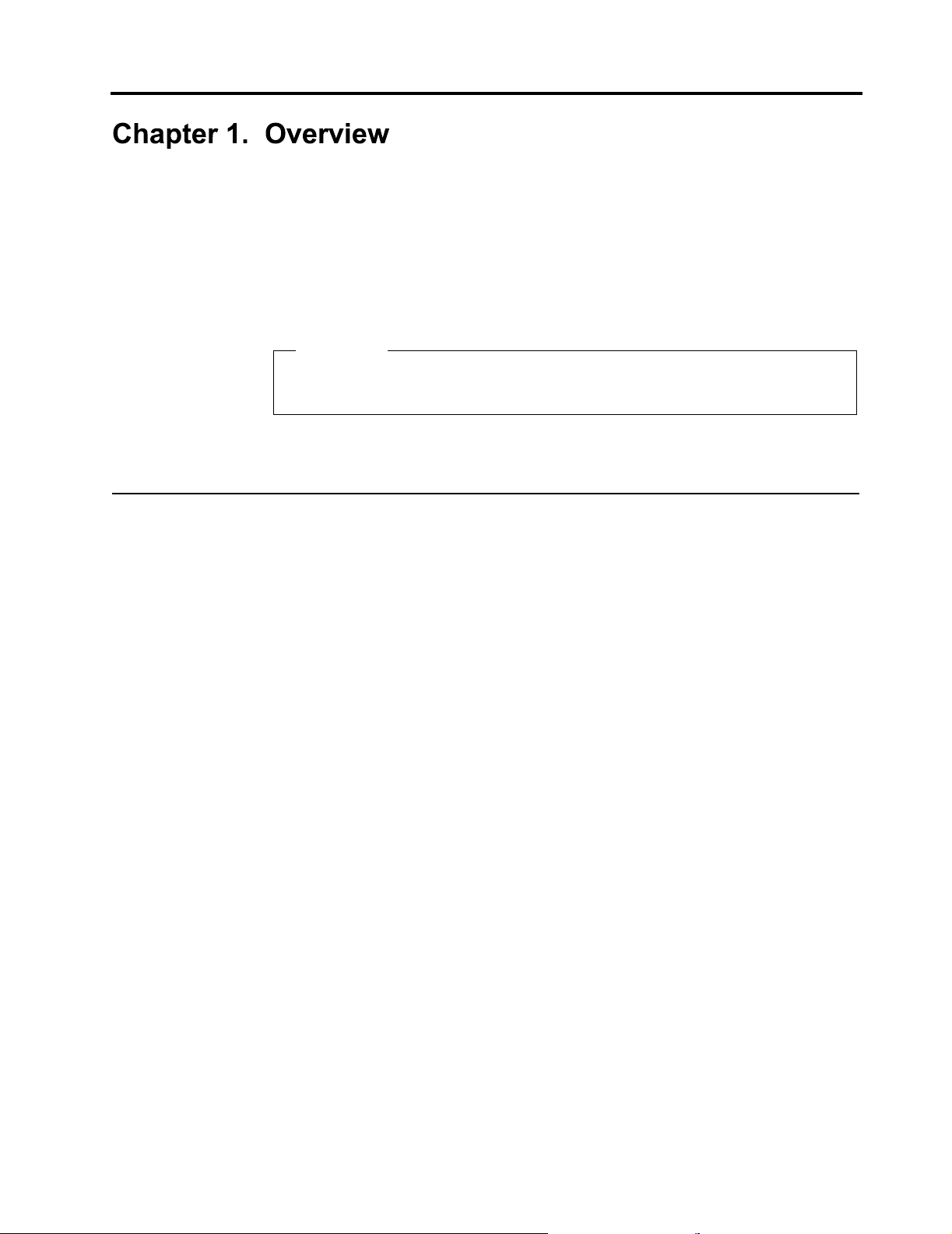
Desktop model computer
Desktop models come with a hard disk drive and diskette drive (only some models). Some
models come with a CD-ROM, DVD-ROM, or Combo drive. The power button is located on the
right side of the computer as you are facing it.
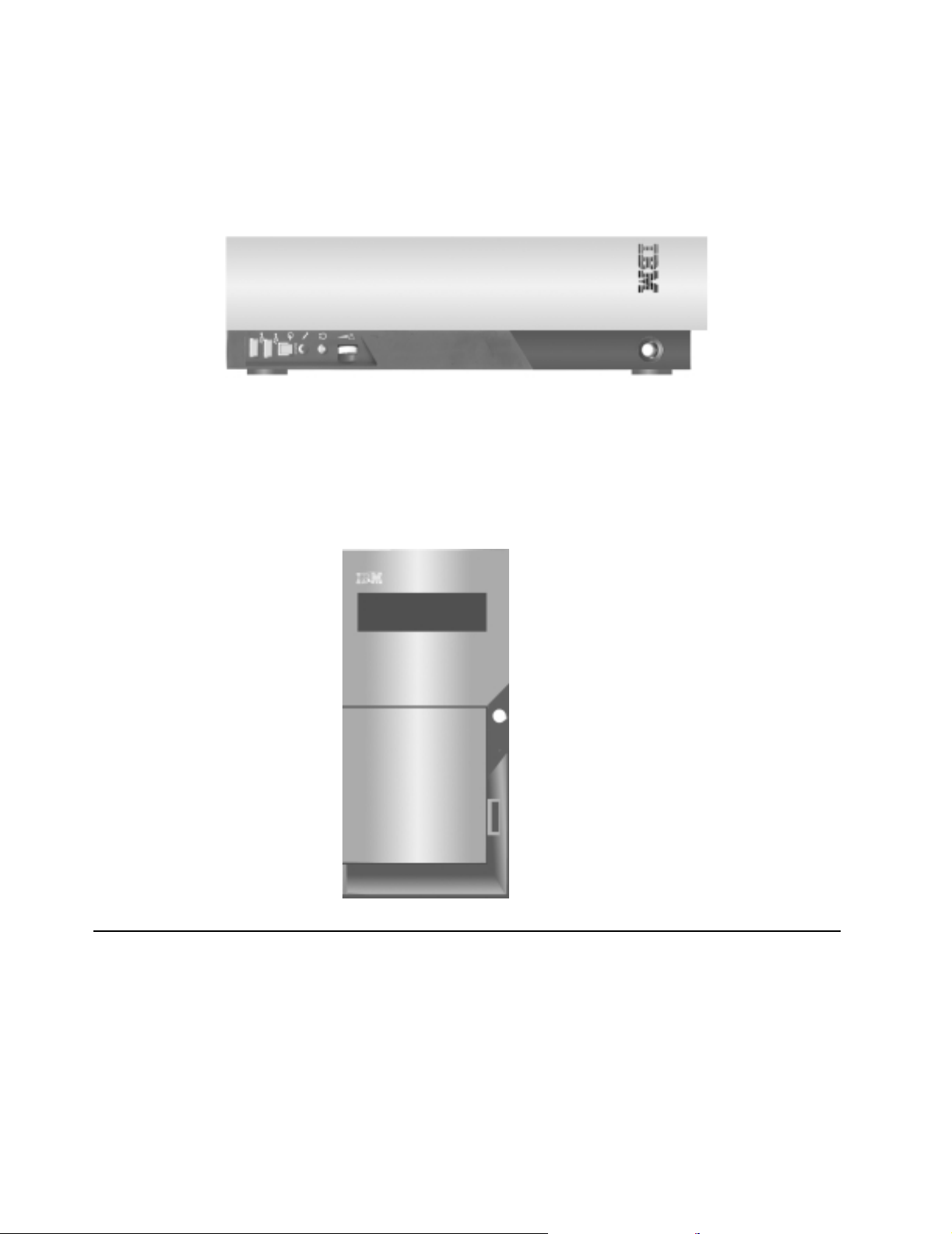
Microtower model computer
Microtower models come with a diskette drive and a hard disk drive. Some models come with a
CD-ROM, DVD-ROM, or Combo drive. The power button is located on the right side of the
computer as you are facing it.
Features
2 Overview
This section provides an overview of the computer features, standard software, and
specifications.
Not all models come with all features that are summarized here.
Microprocessor
AMD Duron™ microprocessor with 128KB L1 cache and 64 KB L2 cache or AMD Athlon™
microprocessor with 128KB L1 cache and 256 KB L2 cache memory
Page 13

Memory
• Support for SDRAM or dual in-line memory modules (DIMMs)
— 3.3 V, synchronous, 168-pin, unbuffered, 133 MHz nonparity dynamic random access
memory (SDRAM)
— 64 MB, 128 MB, and 256 MB unbuffered nonparity DIMMs for a maximum of 512 MB
— DIMM heights of 38.1 mm (1.5 inches)
Internal drives
• 3.5-inch, 1.44 MB diskette drive (some models)
• Internal hard disk drive
• EIDE CD-ROM, CD-RW, DVD-ROM, or Combo drive (some models)
Video controller
• Unified video memory technology
Audio subsystem
• 16-bit integrated Sound Blaster Pro compatible audio subsystem
Connectivity
•Modem
• 10/100 Mb Ethernet
System management features
• Wake on LAN
• Wake on Ring (in the Configuration/Setup Utility program, this feature is called Serial Port
Ring Detect for an external modem and Modem Ring Detect for an internal modem)
• Wake on Alarm
Input/output features
• 25-pin, ECP/EPP parallel connector
• One 9-pin serial connector
• Three or Four USB connectors
• PS/2 mouse connector
• PS/2 keyboard connector
• 15-pin monitor connector
• Audio line-in, Audio line-out and Microphone connectors
• S/PDIF connector (some models only)
• IEEE 1394 connector (some models only)
• Game port (some models only)
Expansion
• Drive bays:
— Desktop model: 3
— Microtower model: 4
• PCI expansion slots
— Desktop model: 3
— Microtower model: 3
• PCMCIA adapter (some desktop models)
Power
• 120 W or 155 W power supply with manual voltage selection switch
• Automatic 50/60 Hz input frequency switching
• Advanced Power Management support
• Advanced Configuration and Power Interface (ACPI) support
Security features
• Power-on and administrator passwords
• Lockable Cover (microtower models only)
• Startup sequence control
3
Page 14

Specifications
IBM standard software
Your computer might come with standard software. If it does, an operating system, device
drivers to support built-in features, and other support programs are included.
Operating systems (supported)
• Microsoft Windows Millennium Edition (Me)
Operating systems (tested for compatibility)
• Microsoft Window 2000
This section lists the physical specifications for the computer. The desktop and microtower
models have three 32-bit PCI expansion slots. The desktop models have three drive bays and
microtower models have 4 drive bays.
Note: The computer is classified as a Class A or Class B digital device. See the Quick
Reference for further information about this classification.
4 Overview
Page 15

Physical specifications-desktop model
Dimensions
Width: 88 mm (3.4 in.)
Height: 305 mm (12.0 in.)
Depth: 380 mm (14.9 in.)
Weight
Minimum configuration as shipped: 8.5 kg (18 lb)
Environment
Air temperature:
System on: 10° to 35° C (50° to 95° F)
System off: 10° to 43° C (50° to 110° F)
Maximum altitude: 2134 m (7000 ft)
Note: The maximum altitude, 2134 m (7000 ft),
is the maximum altitude at which the
specified air temperatures apply. At
higher altitudes, the maximum air
temperatures are lower than those
specified.
Humidity:
System on: 8% to 80%
System off: 8% to 80%
Electrical input
Input voltage:
Low range:
Minimum: 90 V ac
Maximum: 137 V ac
Input frequency range: 57–63 Hz
Voltage switch setting: 115 V ac
High range:
Minimum: 180 V ac
Maximum: 265 V ac
Input frequency range: 47–53 Hz
Voltage switch setting: 230 V ac
Input kilovolt-amperes (kVA) (approximate):
Minimum configuration as shipped: 0.08 kVA
Maximum configuration: 0.30 kVA
Heat output (approximate) in British thermal units (Btu)
per hour:
Minimum configuration: 13.7 Btu/hr (4 watts)
Maximum configuration: 341 Btu/HR (100 watts)
Airflow
Approximately 0.28 cubic meters per minute (10 cubic
feet per minute) maximum
Acoustical noise-emission values
Average sound-pressure levels:
At operator position:
Idle: 38 dBA
Operating: 43 dBA
At bystander position - 1 meter (3.3 ft):
Idle: 33 dBA
Operating: 37 dBA
Declared (upper limit) sound-power levels:
Idle: 3.75 bels
Operating: 4.99 bels
Note: These levels were measured in controlled
acoustical environments according to the
procedures specified by the American
National Standards Institute (ANSI) S12.10
and ISO 7779 and are reported in accordance
with ISO 9296. Actual sound-pressure levels
in a given location might exceed the average
values stated because of room reflections and
other nearby noise sources. The declared
sound-power levels indicate an upper limit,
below which a large number of computers will
operate.
Note: Power consumption and heat output vary
depending on the number and type of optional
features installed and the power-management
optional features in use.
5
Page 16

Physical specifications - microtower model
Dimensions
Width: 385 mm (15.1 in.)
Height: 192 mm (7.5 in.)
Depth: 388 mm (15.2 in.)
Weight
Minimum configuration as shipped: 9.3 kg (20 lb)
Environment
Air temperature:
System on: 10° to 35° C (50° to 95° F)
System off: 10° to 43° C (50° to 110° F)
Maximum altitude: 2134 m (7000 ft)
Note: The maximum altitude, 2134 m (7000 ft),
is the maximum altitude at which the
specified air temperatures apply. At
higher altitudes, the maximum air
temperatures are lower than those
specified.
Humidity:
System on: 8% to 80%
System off: 8% to 80%
Electrical input
Input voltage:
Low range:
Minimum: 90 V ac
Maximum: 137 V ac
Input frequency range: 57–63 Hz
Voltage switch setting: 115 V ac
High range:
Minimum: 180 V ac
Maximum: 265 V ac
Input frequency range: 47–53 Hz
Voltage switch setting: 230 V ac
Input kilovolt-amperes (kVA) (approximate):
Minimum configuration as shipped: 0.08 kVA
Maximum configuration: 0.3 kVA
Heat output (approximate in British thermal units (Btu) per
hour:
Minimum configuration: 13.7 Btu/hr (4 watts)
Maximum configuration: 341 Btu/HR (100 watts)
Airflow
Approximately 0.28 cubic meters per minute (10 cubic
feet per minute) maximum
Acoustical noise-emission values
Average sound-pressure levels:
At operator position:
Idle: 38 dBA
Operating: 43 dBA
At bystander position - 1 meter (3.3 ft):
Idle: 33 dBA
Operating: 37 dBA
Declared (upper limit) sound-power levels:
Idle: 3.75 bels
Operating: 4.99 bels
Note: These levels were measured in controlled
acoustical environments according to the
procedures specified by the American
National Standards Institute (ANSI) S12.10
and ISO 7779 and are reported in accordance
with ISO 9296. Actual sound-pressure levels
in a given location might exceed the average
values stated because of room reflections and
other nearby noise sources. The declared
sound-power levels indicate an upper limit,
below which a large number of computers will
operate.
Note: Power consumption and heat output vary
depending on the number and type of optional
features installed and the power-management
optional features in use.
6 Overview
Page 17

Available options
The following are some available options:
• External options
• Internal options
Tools required
To install some options in your computer, you might need a flat-blade and a Phillips
screwdriver. Additional tools might be needed for certain options. See the instructions that come
with the option.
— Parallel port devices, such as printers and external drives
— Serial port devices, such as external modems and digital cameras
— Audio devices, such as external speakers for the sound system
— USB devices, such as printers and scanners
— Monitor
— System memory
– Dual in-line memory modules (DIMMs)
— Adapters
– Peripheral component interconnect (PCI) adapters
— Internal drives
– CD-ROM drive or DVD-ROM drive
– Hard disk drive
– Diskette drives and other removable media drives
Handling static-sensitive devices
Static electricity, although harmless to you, can seriously damage computer components and
options.
When you add an option, do not open the static-protective package containing the option until
you are instructed to do so.
When you handle options and other computer components, take these precautions to avoid
static electricity damage:
• Limit your movement. Movement can cause static electricity to build up around you.
• Always handle components carefully. Handle adapters and memory modules by the edges.
Never touch any exposed circuitry.
• Prevent others from touching components.
• When you install a new option, touch the static-protective package containing the option to
a metal expansion-slot cover or other unpainted metal surface on the computer for at least
two seconds. This reduces static electricity in the package and your body.
• When possible, remove the option and install it directly in the computer without setting the
option down. When this is not possible, place the static-protective package that the option
came in on a smooth, level surface and place the option on it.
• Do not place the option on the computer cover or other metal surface.
7
Page 18

8 Overview
Page 19
This chapter shows the various external connectors on your computer to which you can attach
external options, such as external speakers, a printer, or a scanner. For some external options,
you must install additional software in addition to making the physical connection. When adding
an external option, use the information in this chapter to identify the required connector, and
then use the instructions that come with the option to help you make the connection and install
any software or device drivers that are required for the option.
Important
Before you install or remove any option, read “Safety Information” on page v. These
precautions and guidelines will help you work safely.
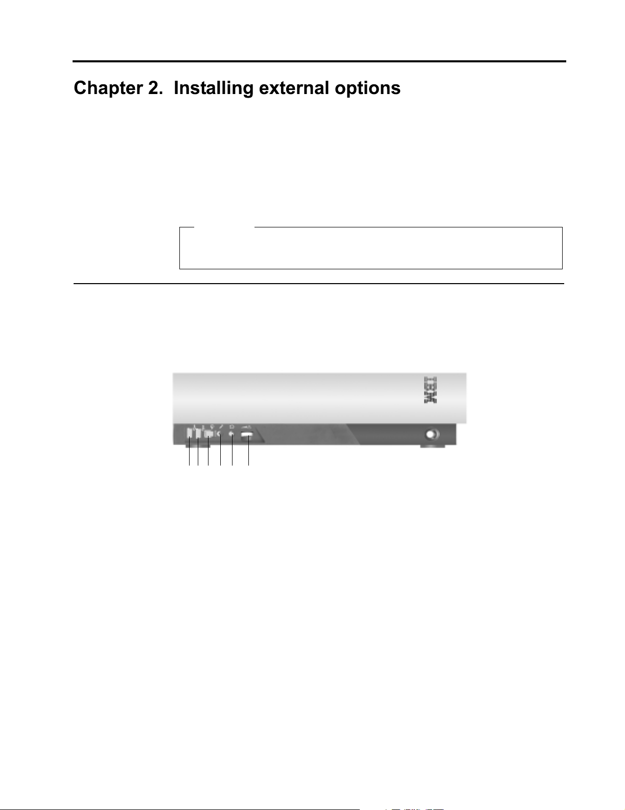
Locating the connectors on the front of your computer
The following illustration shows the location of the connectors on the front of the desktop
computer.
5
2
3
1
6
4
1 USB connector
2 USB connector (Some models are IEEE 1394 connector )
3 S/PDIF connector
4 Microphone connector
5 Headphone connector
6 Volume control knob
9
Page 20
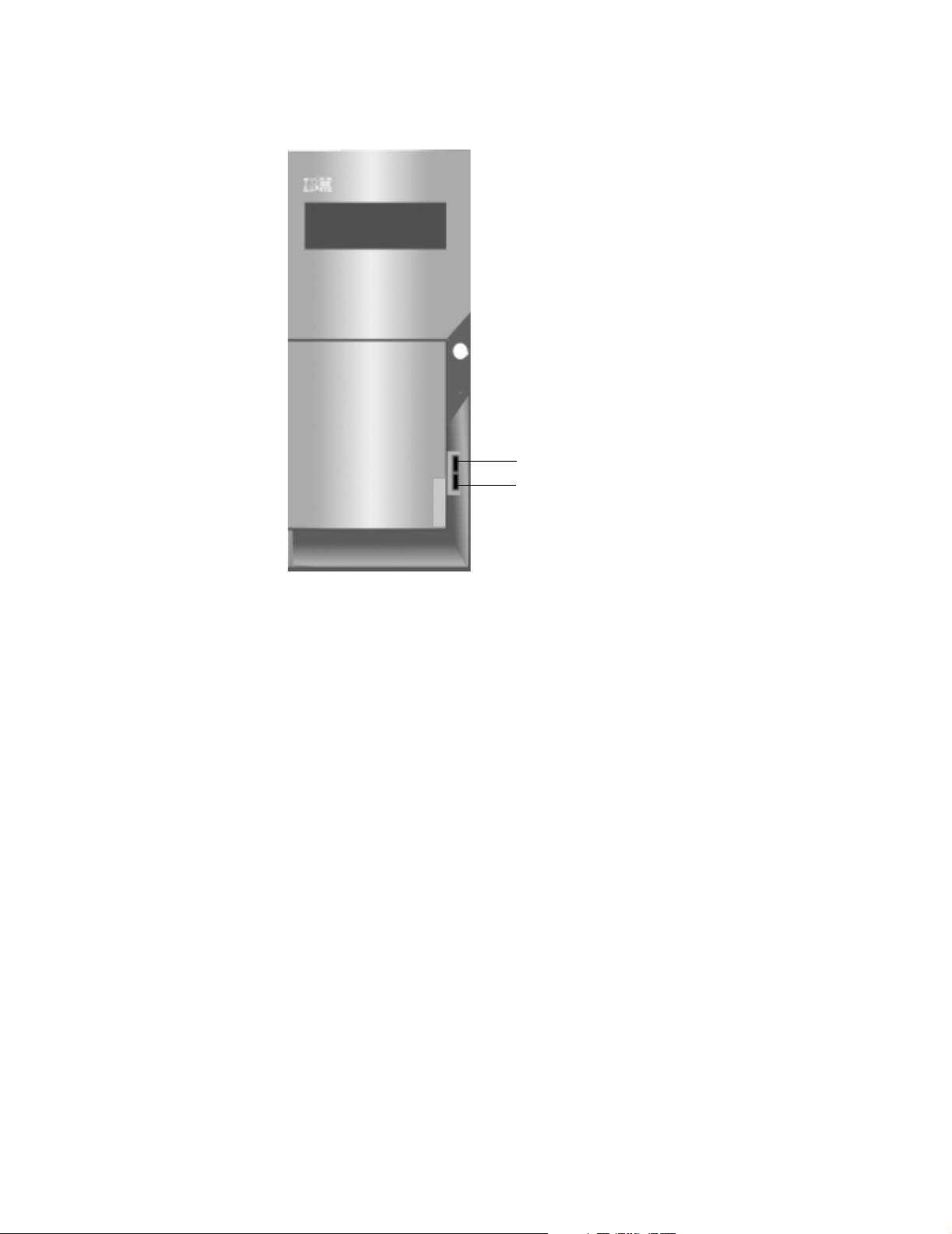
The following illustration shows the location of the connectors on the front of the microtower
computer.
1
2
1 Front USB connector
2 Front USB connector
10Installing external options
Page 21

Locating the connectors on the rear of your computer
The following illustration shows the location of the connectors on the rear of the desktop model.
3
567
14
13
12
11
10
1
9
2
8
1 LAN connector 8 USB connector
2 Game Port (some models only) 9 USB connector
3 Speaker out connector 10 Monitor connector
4 Power connector 11 Parallel connector
5 Microphone connector 12 Serial connector
6 Audio line-in connector 13 Keyboard connector
4
7 Audio line-out connector 14 Mouse connector
Note: The connectors on the rear of the computer have color-coded icons. Icons will help you
to determine where to connect the proper cables on your compute
r.
11
Page 22

The following illustration shows the location of the connectors on the rear of the microtower
model.
15
14
13
12
11
10
9
8
7
6
5
34
1
2
1 Power connector 9 USB connector
2 Speaker out connector 10 USB connector
3 S/PDIF connector (some models only) 11 Monitor connector
4 Game Port (some models only) 12 Parallel connector
5 Microphone connector 13 Serial connector
6 Audio line-in connector 14 Keyboard connector
7 Audio line-out connector 15 Mouse connector
8 LAN connector
Note: The connectors on the rear of the computer have color-coded icons. Icons will help you
to determine where to connect the proper cables on your computer.
Connector Description
Mouse connector Used to attach a mouse, trackball, or other pointing device that uses a mouse
connector.
Keyboard connector Used to attach a keyboard that uses a keyboard connector.
USB connectors Used to attach a device that requires a Universal Serial Bus (USB) connection, such as
a USB scanner or USB printer. If you have more than four USB devices, you can
purchase a USB hub, which you can use to connect additional USB devices.
Serial connectors Used to attach an external modem, serial printer, or other device that uses a 9-pin
serial connector.
Parallel connector Used to attach a parallel printer, parallel scanner, or any other device that requires a
25-pin parallel connection.
12Installing external options
Page 23

Connector Description
Monitor connector Used to attach a monitor. Some models might have two monitor connectors. There is
one on the system board.
Microphone connector Used to attach a microphone to your computer when you want to record voice or other
sounds on the hard disk if you use speech-recognition software.
Audio line-in connector Used to receive audio signals from an external audio device, such as a stereo system.
When you attach an external audio device, a cable is connected between the audio
line-out connector of the device and the audio line-in connector of the computer.
Audio line-out connector Used to send audio signals from the computer to external devices, such as powered
stereo speakers (speakers with built-in amplifiers), headphones, multimedia
keyboards, or the audio line-in connector on a stereo system or other external
recording device.
S/PDIF connector Used to connect personal audio device, for example, minidisk.
Obtaining device drivers
You can obtain device drivers for operating systems that are not standard at
http://www.ibm.com/pc/support/ on the World Wide Web. Installation instructions are provided
in README files with the device driver files.
13
Page 24

14Installing external options
Page 25

You can expand the capabilities of your computer by adding memory, drives, or adapters. When
adding an option, use these instructions along with the instructions that come with the option.
Removing the cover
Important:
Read ”Safety Information” on page v and ”Handling static-sensitive devices” on page 7
before removing the cover.
To remove the cover:
1. Shut down your operating system, remove any media (diskettes, CDs, from the drives, and
turn off all attached devices and the computer.
2. Unplug all power cords from electrical outlets.
3. Disconnect all cables attached to the computer. This includes power cords, input/output
(I/O) cables, and any other cables that are connected to the computer.
4. Remove the screw that secures the top cover at the rear of the system unit.
5. Hold both sides of the system unit top cover and push it foward about 1 inch (2.54cm).
Lift the top cover up to remove it completely.
15
Page 26

Locating components
The following illustration will help you locate the various components in your computer.
1
2
3
4
67
5
1 Power supply 5 Hard disk drive
2 PCI slot 6 CD-ROM, DVD-ROM, or other drive
3 System board 7 Diskette drive (some models only)
4 Microprocessor
Installing options on the system board
This section provides instructions for installing options, such as system memory and adapters,
on the system board.
Accessing the system board
To access the system board, you must remove the computer cover. For information on
removing the computer cover, see ”Removing the cover” on page 15. You might need to remove
adapters to access some components on the system board. For information about adapters,
see ”Installing adapters” on page 19. When disconnecting cables, be sure to note where they
are attached, so that you can correctly reattach them later.
Identifying parts on the system board
The system board, also called the planar or motherboard, is the main circuit board in your
computer. It provides basic computer functions and supports a variety of devices that are IBMinstalled or that you can install later.
16Installing internal options-desktop model
Page 27

1
24
2
3
4
23
22
21
20
19
18
17
16
10
11
12
14
13
15
9
5
6
7
8
Note: An illustration of the system board and additional information is provided on a label
located on the inside of the computer chassis.
1 PS/2 Keyboard and mouse connector 13 PCI Slot 3
2 CPU 462 pin socket 14 S/PDIF connector
3 DIMM 0 15 CD-ROM audio connector
4 DIMM 1 16 Speaker-out connector
5 Diskette drive connector 17 Microphone connector
6 Primary IDE connector 18 Audio line-in connector
7 Secondary IDE connector 19 Audio line-out connector
8 Flash ROM 20 Game Port (some models only)
9 CMOS battery connector 21 2 USB connectors and LAN connector
10 JP7 1-2: normal(default)
22 Monitor connector
2-3: CMOS clear
11 PCI Slot 1 23 Parallel connector
12 PCI Slot 2 24 Serial connetor
17
Page 28

Installing memory
Your computer has two connectors for installing dual in-line memory modules (DIMMs) that
provide up to a maximum of 512 MB of system memory.
Removing a DIMM
To remove a DIMM:
1. Locate the DIMM connectors. See ”Identifying parts on the system board” on page 16.
2. At both ends of the DIMM connector on the system board, slowly but firmly push outward
on the retaining clips until the module is loosened. Lift the DIMM out of the connector.
3. Store the DIMM in a static-protective package. Do not discard or lose this part. It might be
needed later if you change your memory configuration.
Installing a DIMM
When installing DIMMs, the following rules apply:
• Fill each system memory connector sequentially, starting at DIMM 0.
• Use 3.3 V, 133 MHz, unbuffered, SDRAM DIMMs.
• Use only 64, 128, or 256 MB DIMMs in any combination.
To install a DIMM:
1. Touch the static-protective package containing the DIMM to any unpainted metal surface in
the computer, and then remove the DIMM.
2. If the retaining clips are not already open, open them.
3. Position the DIMM above the connector so that the two notches on the bottom edge of the
module align properly with the empty connector.
4. Firmly push the module straight down into the connector until the retaining clips pop up and
fit snugly around both ends of the module.
18Installing internal options-desktop model
Page 29

Installing adapters
This section provides information and instructions for installing and removing adapters.
Adapter slots
Your computer has three expansion slots for peripheral component interconnect (PCI) adapter.
You can install a low profile PCI adapter card .
Installing adapters
To install an adapter:
1. Remove the cover. See ”Removing the cover” on page 15.
2. Remove the slot screw and slot cover for the appropriate expansion slot.
3. Install the adapter into the appropriate slot on the system board.
What to do next:
• To work with another option, go to the appropriate section.
• To complete the installation, go to ”Replacing the cover and connecting the cables”
on page 23.
19
Page 30

Installing internal drives
This section provides information and instructions for installing and removing internal drives.
Internal drives are devices that your computer uses to read and store data. You can add drives
to your computer to increase storage capacity and to enable your computer to read other types
of media. Some of the different drives that are available for your computer are:
• Hard disk drives
• CD-ROM drives
• Removable media drives
Internal drives are installed in bays. Within this book, the bays are referred to as bay 1, bay 2,
and so on.
When you install an internal drive, it is important to note what type and size of drive that you can
install in each bay. Also, it is important to correctly connect the internal drive cables to the
installed drive.
Drive specifications
Your computer comes with the following IBM-installed drives:
• A CD-ROM drive, DVD-ROM, or other type of drive in bay 2 (some models)
• A 3.5-inch hard disk drive in bay 1
• A 3.5-inch diskette drive in bay 3 (some models)
Models that do not have drives installed in bays 2 and 3 have a static shield and bay panel
installed.
The following illustration shows the locations of the drive bays.
3
2
1
The following table describes some of the drives that you can install in each bay and their height
requirements.
Bay 1 - Max Height: 25.4 mm (1.0 in.)
Bay 2 - Max Height: 41.3 mm (1.6 in.)
Bay 3 - Max Height: 25.4 mm (1.0 in.)
Notes:
1.Drives that are greater than 41.3 mm (1.6 in.) high cannot be installed.
2.Install removable media (tape or CD) drives in the accessible bay: bay 2 or 3.
20Installing internal options-desktop model
Page 31

Power and signal cables for internal drives
Your computer uses cables to connect integrated drive electronics (IDE) drives to the power
supply and to the system board. The following cables are provided:
• Four-wire power cables connect most drives to the power supply. At the end of these
cables are plastic connectors that attach to different drives; these connectors vary in size.
Also, certain power cables attach to the system board.
• Flat signal cables, also called ribbon cables, connect IDE and diskette drives to the system
board. There are two sizes of ribbon signal cables that come with your computer:
— The wider signal cable has two or three connectors.
– If the cable has three connectors, one of these connectors is attached to the drive,
one is a spare, and the third is attached to the primary or secondary IDE
connector on the system board.
– If the cable has two connectors, one of these connectors is attached to the hard
disk drive, and the other is attached to the primary or secondary IDE connector on
the system board.
Note: If you want to add another device, and your computer does not come with
a standard CD-ROM, you will need a second signal cable with three
connectors. You will need an 80-conductor ATA 100 signal cable if you are
replacing the existing signal cable or adding a second hard disk drive.
ATA 100 signal cables are color-coded. The blue connector is attached to
the system board, the black connector is attached to the master device,
and the gray middle connector is attached to the secondary (or slave)
device.
If your computer comes with a CD-ROM drive, it has an ATA 100 signal
cable. However, if you are installing a hard disk drive, you must change
the switch or jumper setting on the CD-ROM drive to secondary and
change the connector that is used for the CD-ROM drive to the gray
middle connector.
— The narrower signal cable has two connectors for attaching the diskette drive to the
diskette-drive connector on the system board.
Note: To locate connectors on the system board, see ”Identifying parts on the system board”
on page 16.
The following are some important points to remember when connecting power and signal
cables to internal drives:
• The drives that are standard in your computer come with power and signal cables attached.
If you replace any drives, it is important to remember which cable is attached to which
drive.
• When you install a drive, ensure that the drive connector at the end of the signal cable is
always connected to a drive; also, ensure that the drive connector at the other end is
connected to the system board. This reduces electronic noise from the computer.
• If two IDE devices are used on a single cable, one must be designated as the primary, or
master, device and the other as the secondary, or slave, device; otherwise, some of the
IDE devices might not be recognized by the computer. The primary or secondary
designation is determined by switch or jumper settings on each IDE device.
• If two IDE devices are on a single cable and only one is a hard disk drive, the hard disk
drive must be set as the master device.
• If you have only one IDE device on a cable, it must be set as master.
For help in selecting drives, cables, and other options for your computer, see ”Available options”
on page 7.
21
Page 32

Installing internal drives
To install an internal drive, following these steps.
Note: If your computer has a CD-ROM drive, you might need to remove the signal and power
1. Remove the cover (see ”Removing the cover” on page 15).
2. Lift the latch that secures the CD-ROM drive mounting tray.
cables from the drive.
3. Install the drive into the bay. Align the screw holes and insert the two screws.
4. Slide in the drive and engage the latch to secure drive cage.
5. Connect the power and signal cables to the drive.
22Installing internal options-desktop model
Page 33

Replacing the cover and connecting the cables
After working with options, you need to install any removed parts, replace the cover, and
reconnect any cables, including power cords and telephone lines. Also, depending on the option
that is installed, you might need to confirm the updated information in the Configuration/Setup
Utility program.
To replace the cover and connect cables to your computer:
1. Ensure that all components have been reassembled correctly and that no tools or loose
screws are left inside your computer.
2. Clear any cables that might impede the replacement of the cover.
3. Place the cover over the computer and slide it to the rear until it is fully closed.
4. Reconnect the external cables and cords to the computer. See “Chapter 2. Installing
external options,” on page 9.
5. To update the configuration, see “Chapter 5. Updating the computer configuration,” on
page 37.
23
Page 34

24Installing internal options-desktop model
Page 35

You can expand the capabilities of your computer by adding memory, drives, or adapters. When
adding an option, use these instructions along with the instructions that come with the option.
Removing the cover
Important:
Read “Safety Information” on page v and “Handling static-sensitive devices” on page 7
before removing the cover.
To remove the cover:
1. Shut down your operating system, remove any media (diskettes, CDs, or tapes) from the
drives, and turn off all attached devices and the computer.
2. Unplug all power cords from electrical outlets.
3. Disconnect all cables attached to the computer. This includes power cords, input/output
(I/O) cables, and any other cables that connected to the computer.
4. Remove the thumbscrews from the rear of the computer and slide the cover toward the rear
of the computer and lift the cover up and off.
25
Page 36

Locating components
The following illustration will help you locate the various components in your computer.
7
6
5
4
3
2
1
1 PCI slot 5 Diskette drive
2 System board 6 Optional drive bay
3 Hard disk drive 7 CD/DVD drive bay
4 Power supply
Removing the power supply
To perform some operations inside the computer, you might need to move the power supply to
access parts of the system board that are difficult to see or hard to reach. Use the following
procedure to provide easier access to the system board.
26Installing internal options-microtower model
Page 37

1. Remove the screw securing the power supply to the rear of the chassis.
2. Slide the power supply unit up toward the top of the chassis.
3. Rotate the power supply outward as shown.
4. Pull the power supply forward and carefully rotate it toward the front of the chassis. Lay it to
the side.
5. To replace the power supply, reverse these steps.
27
Page 38

Installing options on the system board
This section provides instructions for installing options, such as system memory and adapters,
on the system board.
Accessing the system board
To access the system board, you must remove the computer cover. For information on
removing the computer cover, see “Removing the cover” on page 25. You might need to move
the power supply aside or remove adapters to access some components on the system board.
For information about adapters, see “Installing adapters” on page 31. When disconnecting
cables, be sure to note where they are attached, so that you can correctly reattach them later.
Identifying parts on the system board
The system board, also called the planar or motherboard, is the main circuit board in your
computer. It provides basic computer functions and supports a variety of devices that are IBM-
installed or that you can install later.
28Installing internal options-microtower model
Page 39

1
24
23
22
21
20
19
18
17
16
14
13
15
2
10
11
12
3
4
5
6
7
8
9
Note: An illustration of the system board and additional information is provided on a label
located on the inside of the computer chassis.
1 PS/2 Keyboard and mouse connector 13 PCI Slot 3
2 CPU 462 pin socket 14 S/PDIF connector
3 DIMM 0 15 CD-ROM audio connector
4 DIMM 1 16 Speaker-out connector
5 Diskette drive connector 17 Microphone connector
6 Primary IDE connector 18 Audio line-in connector
7 Secondary IDE connector 19 Audio line-out connector
8 Flash ROM 20 Game Port (some models only)
9 CMOS battery connector 21 2 USB connectors and LAN connector
10 JP7 1-2: normal(default)
22 Monitor connector
2-3: CMOS clear
11 PCI Slot 1 23 Parallel connector
12 PCI Slot 2 24 Serial connetor
29
Page 40

Installing memory
Your computer has two connectors for installing dual in-line memory modules (DIMMs) that
provide up to a maximum of 512 MB of system memory.
Removing a DIMM
To remove a DIMM:
1. Locate the DIMM connectors. See “Identifying parts on the system board” on page 28.
2. At both ends of the DIMM connector on the system board, slowly but firmly push outward
on the retaining clips until the module is loosened. Lift the DIMM out of the connector.
3. Store the DIMM in a static-protective package. Do not discard or lose this part. It might be
needed later if you change your memory configuration.
Installing DIMMs
When installing DIMMs, the following rules apply:
• Fill each system memory connector sequentially, starting at DIMM 0.
• Use 3.3 V, 133 MHz, unbuffered, SDRAM DIMMs.
• Use only 64, 128, or 256 MB DIMMs in any combination.
To install a DIMM:
1. To locate the DIMM connectors. See “Identifying parts on the system board” on page 28.
2. If the retaining clips are not already open, open them.
3. Position the DIMM above the connector so that the two notches on the bottom edge of the
module align properly with the empty connector.
4. Firmly push the module straight down into the connector until the retaining clips pop up and
fit snugly around both ends of the module.
30Installing internal options-microtower model
Page 41

Installing adapters
This section provides information and instructions for installing and removing adapters.
Adapter slots
Your computer has three expansion slots for peripheral component interconnect (PCI) adapters.
You can install an adapter with length in 270 mm(10.6 in.), width in 106 mm(4.1 in.), and
thickness in 12 mm(0.47 in.).
Installing adapters
To install an adapter:
1. Remove the cover. See “Removing the cover” on page 25.
2. Remove the slot screw and slot cover for the appropriate expansion slot.
3. Remove the adapter from its static-protective package.
4. Install the adapter into the appropriate slot on the system board.
5. Install the screw that secures the adapter.
Installing internal drives
This section provides information and instructions for installing and removing internal drives.
Internal drives are devices that your computer uses to read and store data. You can add drives
to your computer to increase storage capacity and to enable your computer to read other types
of media. Some of the different drives that are available for your computer are:
• Hard disk drives
• CD-ROM drives or DVD-ROM drives
•Removable media drives
Internal drives are installed in bays. Within this book, the bays are referred to as bay 1, bay 2,
and so on.
When you install an internal drive, it is important to note what type and size of drive that you can
install in each bay. Also, it is important to correctly connect the internal drive cables to the
installed drive.
31
Page 42

Drive specifications
Your computer comes with the following IBM-installed drives:
• A CD-ROM, DVD-ROM, or other type of drive in bay 1
• An optional drive in bay 2
• A 3.5-inch diskette drive in bay 3
• A 3.5-inch hard disk drive in bay 4
Models that do not have drives installed in bays 1 and 2 have a static shield and bay panel
installed. The following illustration shows the locations of the drive bays.
1
2
3
4
The following table describes some of the drives that you can install in each bay and their height
requirements.
Bay 1 - Max Height: 41.3 mm (1.6 in.)
Bay 2 - Max Height: 41.3 mm (1.6 in.)
Bay 3 - Max Height: 25.4 mm (1.0 in.)
Bay 4 - Max Height: 25.4 mm (1.0 in.)
Notes:
1.Drives that are greater than 41.3 mm (1.6 in.) high cannot be installed.
2.Install removable media (tape or CD) drives in the accessible bays: bays 1 or 2.
32Installing internal options-microtower model
Page 43

Power and signal cables for internal drives
Your computer uses cables to connect integrated drive electronics (IDE) drives to the power
supply and to the system board. The following cables are provided:
• Four-wire power cables connect most drives to the power supply. At the end of these
cables are plastic connectors that attach to different drives; these connectors vary in size.
Also, certain power cables attach to the system board.
• Flat signal cables, also called ribbon cables, connect IDE and diskette drives to the system
board. There are two sizes of ribbon signal cables that come with your computer:
— The wider signal cable has two or three connectors.
– If the cable has three connectors, one of these connectors is attached to the drive,
one is a spare, and the third is attached to the primary or secondary IDE
connector on the system board.
– If the cable has two connectors, one of these connectors is attached to the hard
disk drive, and the other is attached to the primary or secondary IDE connector on
the system board.
Note: If you want to add another device, and your computer does not come with
a standard CD-ROM drive or DVD-ROM drive , you will need a second
signal cable with three connectors. You will need an 80-conductor ATA
100 signal cable if you are replacing the existing signal cable or adding a
second hard disk drive. ATA 100 signal cables are color-coded. The blue
connector is attached to the system board, the black connector is
attached to the master device, and the gray middle connector is attached
to the secondary (or slave) device.
If your computer comes with a CD-ROM drive or DVD-ROM drive, it has
an ATA 100 signal cable. However, if you are installing a hard disk drive,
you must change the switch or jumper setting on the CD-ROM drive or
DVD-ROM drive to secondary and change the connector that is used for
the CD-ROM drive or DVD-ROM drive to the gray middle connector.
— The narrower signal cable has two connectors for attaching the diskette drive to the
diskette-drive connector on the system board.
Note: To locate connectors on the system board, see “Identifying parts on the system board”
The following are some important points to remember when connecting power and signal
cables to internal drives:
• The drives that are standard in your computer come with power and signal cables attached.
• When you install a drive, ensure that the drive connector at the end of the signal cable is
• If two IDE devices are used on a single cable, one must be designated as the primary, or
• If two IDE devices are on a single cable and only one is a hard disk drive, the hard disk
• If you have only one IDE device on a cable, it must be set as master.
on page 28.
If you replace any drives, it is important to remember which cable is attached to which
drive.
always connected to a drive; also, ensure that the drive connector at the other end is
connected to the system board. This reduces electronic noise from the computer.
master, device and the other as the secondary, or slave, device; otherwise, some of the
IDE devices might not be recognized by the computer. The primary or secondary
designation is determined by switch or jumper settings on each IDE device.
drive must be set as the master device.
Installing internal drives
To install an internal drive:
1. Remove the cover (see “Removing the cover” on page 25).
Note: If your computer has a CD-ROM drive or DVD-ROM drive, you might need to
remove the signal and power cables from the drive.
33
Page 44

2. Remove the bay panel, and insert a flat-blade screwdriver into one of the slots on the static
shield in the drive bay into which you are installing the drive. Gently pry the static shield
loose from the drive bay.
3. Install the drive into the bay. Align the screw holes and insert the two screws.
4. If the drive you installed is a removable-media drive, place the bezel frame that comes with
your computer over the drive bay.
What to do next
• To work with another option, go to the appropriate section.
• To complete the installation, go to “Replacing the cover and connecting the cables”
on page 34.
Replacing the cover and connecting the cables
After working with options, you need to install any removed parts, replace the cover, and
reconnect any cables, including power cords and telephone lines. Also, depending on the option
that installed, you might need to confirm the updated information in the Configuration/Setup
Utility program.
To replace the cover and connect cables to your computer:
1. Ensure that all components have been reassembled correctly and that no tools or loose
screws are left inside your computer.
2. Clear any cables that might impede the replacement of the cover.
34Installing internal options-microtower model
Page 45

3. Position the cover over the chassis so that the front edge is approximately one inch away
from the front bezel.
4. Lower the cover down over the chassis so that the rail guides engage the rails.
5. Slide the cover forward. You might need to lift the front of the cover slightly to align it
properly.
6. Insert the three thumbscrews into the holes in the cover and the chassis and tighten.
7. Reconnect the external cables and cords to the computer. See “Installing external options”
on page 9.
Important:
When the power cord is first plugged in, the computer might appear to power on for a
few seconds, then power off. This is a normal sequence to enable the computer to
self-initialize.
35
Page 46

36Installing internal options-microtower model
Page 47

This chapter includes information about updating configuration settings. Your IBM Personal
Computer is already configured for immediate use. You can view your computer’s configuration
settings using the Configuration/Setup Utility. The Configuration/Setup Utility lets you view and
change important information about your computer and its hardware.The Configuration/Setup
Utility menu appears immediately after you press F1.
Configuration/Setup Utility menu
Configuration/Setup Utility
Select option:
System Summary
Product Data
Devices and I/O Ports
Start Options
Date and Time
Advanced Setup
Power Management Setup
Frequency Control
Load FDDless Defaults
Load Optimized Defaults
Set Administrator Password
Set User Password
Save & Exit Setup
Exit Without Saving
Move
Enter:select
F10:Save
F2:General Help
Esc:Exit
Note: The Configuration/Setup Utility menu that you see on your computer may look slightly
different from the menu shown here, but the options will operate just the same.
The Configuration/Setup Utility menu lists system configuration options. When you select one of
these options, a menu for that option appears.
The following table lists specific keys on the keyboard that will help you move through the Setup
menus.
Keys Function
↑ ↓ Use these arrow keys to highlight an option in a menu. (Press the Enter key to choose
the option.)
← → Use these arrow keys to change the value of a setting. In some menus, you can use
these keys to move from one field to another.
F10 Press this key to save your changes.
Enter Press this key to select a highlighted option from a menu.
Esc After viewing or making changes to the settings on a menu, press this
key to exit from the menu.
F2 Press this key if you want help for a selected item in a menu.
+ - Use the + and - keys to change the value in the Date and Time setting
menu.
Note: Not all of the above keys are available on every menu. The available keys in a menu
appear on the bottom of that menu.
37
Page 48

Viewing system information and product data
To view general hardware information about your computer, select the System Summary
option from the Configuration/Setup Utility menu. The items displayed in the System
Information menu are not configurable. Setup automatically updates this menu when you do
either of the following:
• Add or change hardware on your computer
• Make changes to other menus in Setup and save those changes
To view other computer information such as the model number, serial number, and BIOS
version and date, select the Product Data option from the Configuration/Setup Utility menu.
Like in the System Information menu, the items displayed are not configurable.
Changing parameter settings
In the Setup menus, all configuration information that you can change is enclosed in
brackets like these: [ ]. You cannot change any information that is not enclosed inbrackets.
Use the up- or down-arrow keys to highlight options then press Enter to display a menu.
When changing the setting of a particular parameter, highlight the setting then use the left- or
right-arrow key to change the setting.
Load FDDless Defaults
For models that do not include a diskette drive, this option allows you to reload optimized
settings for operating without a diskette drive.
If you have made changes in Setup but would like to restore the default settings, follow these
steps:
1.From the Configuration/Steup Utility menu, highlight the option, then press
Enter. A dialog box appears confirming if you want to Load FDDless Defaults.
2.Type Y to select Yes, then press Enter.
3.Highlight the Save & Exit Setup Option, then press Enter. A dialog box appears
SAVE to CMOS and EXIT(Y/N)?
Load Optimized Defaults
When you purchase an IBM personal computer, it is already configured for use. The original
configuration settings, also called factory or default settings, are stored in the CMOS. Setup
includes an option, Load Optimized Defaults, that lets you reload the original configuration at
any time. If you have made changes in Setup but would like to restore the default settings,
follow these steps:
1. From the Configuration/Setup Utility menu, highlight the option Load Optimized Defaults
then press Enter. A dialog box appears confirming if you want to Load Optimized Defaults.
2. Type Y to select Yes, then press Enter.
3. Highlight the Save & Exit Setup option, then press Enter. A dialog box appears saying
“SAVE to CMOS and EXIT (Y/N)?”
Canceling the default settings
You might make changes to the Setup parameter that you do not want to keep. To cancel the
changes that you have made, follow these steps:
1. Return to the Configuration/Setup Utility menu
2. Highlight the Exit Without Saving option then press Enter and Y. Then press Enter again.
The Setup program then clears all the changes that you made and resets the parameters to
the previous settings. These settings are the settings that were in place when you started
Setup.
38 Updating the computer configuration
Page 49

Exiting Setup
When you have finished viewing the settings and making changes, press Esc to return to the
Configuration/Setup Utility menu. From this location, you can exit Setup and save your
changes or exit without saving your changes.
To exit Setup without saving the changes, follow these steps:
1. From the Configuration/Setup Utility menu, press the Esc key.
2. A dialog box appears saying "Quit without Saving (Y/N)? ". Type Y, and then press Enter.
Note: You also can Exit the Setup by highlighting the Save & Exit Setup option or Exit
without Saving option and follow the dialog box directions.
To exit setup and save the changes, follow these steps:
1. From the Configuration/Setup Utility menu, select Save and Exit Setup. Then, press Enter.
2. A dialog box appears saying "Save to CMOS and EXIT (Y/N)? ". Type Y, and then press
Enter. The computer restarts using the new settings.
Start Options
The start options are settings that affect the way your computer acts when started.
Startup Sequence
This setting controls which devices your computer will attempt to read data from when it is
started.
Your computer can be started from several devices, including the hard disk drive, diskette
drive, and CD-ROM drive. The startup program looks for these devices in a selected
sequence. The startup sequence on your computer is preset from the factory to have the
computer start up from a CD-ROM, diskette, or hard disk. This startup sequence allows you
to start the diagnostic and recovery programs from the Product Recovery and Diagnostics
CD, use emergency diskettes to recover from a startup failure, and start from your hard disk
for normal day-to-day operation. In order to boot from the CD-ROM, place CD Drive before
HDD in the boot sequence list.
Virus Warning
This setting determines if the BIOS will monitor the boot sector and partition table of the hard
disk drive for any attempt at modification. If any attempt is made, the BIOS will halt the
system and an error message will appear.
Afterwards, if necessary, you will be able to run an anti-virus program to locate and remove
the problem before any damage is done.
Enabled Activates automatically when the system boots up causing a warning message
Disabled No warning message will appear when anything attempts to access the boot
Note: Many disk diagnostic programs that attempt to access the boot sector table can
to appear when anything attempts to access the boot sector or hard disk
partition table.
sector or hard disk partition table.
cause the above warning message. If you are running such a program, you can
avoid the virus warning by disabling the virus protection before you run the program.
After running the program, remember to re-enable virus protection.
Quick Power-On Self Test
This setting causes the computer to run a shortened power-on self test (POST). The
shortened POST takes less time to complete, but does not test the computer as thoroughly
as the normal POST.
Enabled Enable quick POST
Disabled Normal POST
39
Page 50

Boot Up Floppy Seek
This setting determines whether or not the computer will check for the presence of a diskette
drive at startup.
Boot Up NumLock Status
This setting determines the default state of the numeric keypad. By default, the system boots
up with NumLock on.
On The numeric keypad provides numeric functions.
Off The numeric keypad provides arrow-key, Home, PgUp, PgDn, End, Insert, and Delete
functions.
Gate A20 Option
This entry allows you to select how the gate A20 is handled. The gate A20 is a device used
to address memory above 1 Mbytes. Initially, the gate A20 was handled via a pin on the
keyboard. Today, while keyboards still provide this support, it is more common, and much
faster, for the system chipset to provide support for gate A20.
Normal keyboard
Fast chipset
Typematic Rate Setting
This setting determines whether or not the typematic (repeat) function is enabled. If the
typematic function is enabled and a key is held down, the key will repeat after a brief delay. If
the typematic function is disabled, the key will not repeat when held brief delay. If the
typematic function is disabled, the key will not repeat when held.
Enabled Enable typematic rate (repeat)
Disabled Disable typematic rate (no repeat)
Typematic Rate (Chars/Sec)
When the typematic rate is enabled, you can select the rate at which the keys are repeated.
Typematic Delay (Msec)
When the typematic rate is enabled, you can select the delay between when the key was first
depressed and when the acceleration begins.
Halt When Error occurence
This option allows system halt when POST error occur. Select "Enabled" system will halt and
"Disabled" system will halt for 5 seconds then POST continues
Halt On
Use this setting to determine under what conditions the power-on self test (POST) will halt
when errors are detected.
ALL errors System halts in case of any errors
No errors System won’t halt in case of any errors
ALL, But keyboard System halts except for the keyboard error
ALL, But diskette System halts except for the diskette error
ALL, But disk/key System halts except for the diskette or keyboard error
.
40 Updating the computer configuration
Page 51

Date and Time
Use this setting to set the date and time.
Advanced Setup
You can use these features to configure advanced hardware features. Do not attempt to
change these settings unless you have an advanced technical knowledge of computer
hardware. If these settings are configured incorrectly, the computer might not function
correctly.
Power Management Setup
The Power Management Setup allows you to configure your system to use the most effective
method of saving energy, while operating in a manner consistent with your own style of
computer use.
Set Administrator Password
In this option, you can set up a password to restrict access to the Setup Utility. You can also
change or remove the password.
If you set up a password for entering setup, you must type this password each time you want
to enter the Setup utility. If you do not type the correct password, you cannot enter Setup.
If you set up a password in this option, you can view and change the setting in the
Configuration/Setup Utility.
Set User Password
In this option, you can set up a password to restrict access to the Setup Utility or to your
system. You can also change or remove the password.
If you set up a system password, you must type this password each time you power on your
system.
If you set up a password in this option, you can only enter and view the setting in the
Configuration/Setup Utility.
Erasing a lost or forgotten password (clearing CMOS)
This section will explain how to remove the password or clear it.
To erase a forgotten password:
1. Turn off the computer and all attached devices.
2. Unplug the power cord.
3. Remove the cover. See ”Removing the cover” on page 15 (desktop models) and
”Removing the cover” on page 25 (microtower models).
4. Refer to ”Identifying parts on the system board” on page 16 (desktop models) and
”Installing options on the system board” on page 28 (microtower models).
5. Move the jumper JP7 from the “normal“ position to “CMOS clear“ position, then move
the jumper JP7 back to the “normal“ position.
6. Replace the cover and plug in the power cord. See ”Replacing the cover and connecting
the cables” on page 23 (desktop models), and ”Replacing the cover and connecting the
cables” on page 34 (microtower models).
7. Restart the computer, leave it on for approximately 10 seconds, and then turn off the
computer.
41
Page 52

42 Updating the computer configuration
Page 53

Your computer has a special type of memory that maintains the date, time, and settings for
built-in features, such as serial- and parallel-port assignments (configuration). A battery keeps
this information active when you turn off the computer.
The battery requires no charging or maintenance throughout its life; however, no battery lasts
forever. If the battery fails, the date, time, and configuration information (including passwords)
are lost. An error message is displayed when you turn on the computer.
Refer to “Lithium battery notice” on page vi for information about replacing and disposing of the
battery.
To change the battery:
1. Turn off the computer and all attached devices.
2. Unplug the power cord and remove the cover. See “Removing the cover” on page 15
(desktop model), “Removing the cover” on page 25 (microtower model).
3. Locate the battery. Refer to the system board label inside your computer or see “Identifying
parts on the system board” on page 16 (desktop model), or “Identifying parts on the system
board” on page 28 (microtower model).
4. If necessary, remove any adapters that impede access to the battery. See “Installing
adapters” on page 19 (desktop model), or “Installing adapters” on page 31 (microtower) for
more information.
5. Remove the old battery.
43
Page 54

6. Install the new battery.
7. Replace any adapters that were removed to gain access to the battery. See “Installing
adapters” on page 19 (desktop model), or “Installing adapters” on page 31 (microtower
model) for instructions for replacing adapters.
8. Replace the cover and plug in the power cord. See “Replacing the cover and connecting
the cables” on page 23 (desktop model), “Replacing the cover and connecting the cables”
on page 34 (microtower model) and the Quick Reference.
Note: When the computer is turned on for the first time after battery replacement, an error
message might be displayed. This is normal after replacing the battery.
9. Turn on the computer and all attached devices.
10. Use the Configuration/Setup Utility program to set the date and time and any passwords.
11. Dispose of the old battery as required by local ordinances or regulations.
44 Changing the battery
Page 55

The following contains information about updating system programs (POST/BIOS) and how to
recover from a POST/BIOS update failure.
System programs
System programs are the basic layer of software built into your computer. They include the
power-on self-test (POST), the basic input/output system (BIOS) code, and the
Configuration/Setup Utility program. POST is a set of tests and procedures that is performed
each time you turn on your computer. BIOS is a layer of software that translates instructions
from other layers of software into electrical signals that the computer hardware can understand.
You can use the Configuration/Setup Utility program to view and change the configuration and
setup of your computer.
Your computer system board has a module called electrically erasable programmable read-only
memory (EEPROM, also referred to as flash memory). You can easily update POST, BIOS, and
the Configuration/Setup Utility program by starting your computer using a flash update diskette
or by using the Remote Administration feature, if it is enabled.
IBM might make changes and enhancements to the system programs. When updates are
released, they are available as downloadable files on the World Wide Web (see Quick
Reference). Instructions for using the system programs updates are available in a README file
included in the update files.
To update system programs (flash the EEPROM):
1. Insert a system programs update (flash) diskette into the diskette drive (drive A) in your
2. Turn on the computer. If it is on already, you must turn it off and back on again. The update
computer. System programs updates are available at http://www.ibm.com/pc/support/ on
the World Wide Web.
begins.
45
Page 56

46Updating System Programs
Page 57

The following charts represent how the hard disk stores different types of information. Address
ranges and byte sizes are approximate.
System memory map
The first 640 KB of system board RAM is mapped starting at address hex 00000000. A 256 byte
area and a 1 KB area of this RAM are reserved for BIOS data. Memory can be mapped
differently if POST detects an error.
Table 1. System memory map.
I/O address map
The following table lists resource assignments for the I/O address map. Any addresses that are
not shown are reserved.
Table 2. I/O address map.
Address range
(decimal)
0~640 KB (000000 ~ 09FFFF) Main memory
640~768 KB (0A0000 ~ 0BFFFF) VGA memory
768~816 KB (0C0000 ~ CBFFFF) Video BIOS Memory
816~896 KB (0CC000 ~ 0DFFFF) ISA Card BIOS & Buffer Memory
896~960 KB (0E0000 ~ 0EFFFF)
960~1024 KB (0F0000 ~ 0FFFFF) System BIOS memory
Address range (hex) Description
BIOS Extension Memory
Setup and Post Memory
PCI Development BIOS
(100000 ~ Upper Limit) Main memory
(Upper Limit ~ 4 GB) PCI memory
Address (hex) Description
000-00F DMA controller-1
0020 – 0021 Interrupt controller 1
0022 – 003F General I/0 locations, available to PCI bus
040-043 System timer
060-060 Keyboard controller 8742
061-061 System Speaker
070-071 CMOS RAM Address and Real Time Clock
081-08F DMA controller-2
0A0-0A1 Interrupt controller-2
47
Page 58

Table 2. I/O address map.
Address (hex) Description
0C0-0DF DMA controller-2
0F0-0FF Math Co-Processor
170-177 Secondary IDE
1F0-1F7 Primary IDE
200-207 Game Port (some models only)
278-27F Parallel Printer Port 2
2F8-2FF Serial Asynchronous Port 2
378-37F Parallel Printer Port 1
3F0-3F5 Floppy Disk Controller
3F6-3F6 Secondary EIDE
3F7-3F7 Primary EIDE
3F8-3FF Serial Asynchronous Port 1
0CF8 Configuration Address Register
0CFC Configuration Data Register
778-77A Parallel Printer Port 1
48System address maps
Page 59

The following tables list one possible assignment for the IRQs and DMA channels.
Table 3. IRQ channel assignments.
IRQ System resource
NMI Critical system error
SMI System-management interrupt for power management
0Timer
1 Keyboard
2 Cascade interrupt from slave PIC
3COM2
4USB
5 Modem
6 Diskette controller
7LPT1
8 Real-time clock
9ACPI
10 Audio and IEEE1394
11 Ethernet, Video and Cardbus
12 Mouse port
13 Math coprocessor
14 Primary IDE (if present)
15 Secondary IDE (if present)
49
Page 60

Table 4. DMA channel assignments.
DMA channel Assignment
0 Available
1Audio
2 Floppy Diskette
3 Printer Port
4 Cascade
5 Available
6 Available
7 Available
50Interrupt request and direct memory access channel assignments
Page 61

This publication was developed for products and services offered in the U.S.A.
IBM may not offer the products, services, or features discussed in this document in other
countries. Consult your local IBM representative for information on the products and services
currently available in your area. Any reference to an IBM product, program, or service is not
intended to state or imply that only that IBM product, program, or service may be used. Any
functionally equivalent product, program, or service that does not infringe any IBM lectual
property right may be used instead. However, it is the user’s responsibility to evaluate and verify
the operation of any non-IBM product, program, or service.
IBM may have patents or pending patent applications covering subject matter described in this
document. The furnishing of this document does not give you any license to these patents. You
can send license inquiries, in writing, to:
IBM Director of Licensing
IBM Corporation
North Castle Drive
Armonk, NY 10504-1785
U.S.A.
The following paragraph does not apply to the United Kingdom or any country where
such provisions are inconsistent with local law: INTERNATIONAL BUSINESS MACHINES
CORPORATION PROVIDES THIS PUBLICATION "AS IS" WITHOUT WARRANTY OF ANY
KIND, EITHER EXPRESS OR IMPLIED, INCLUDING, BUT NOT LIMITED TO, THE IMPLIED
WARRANTIES OF NON-INFRINGEMENT, MERCHANTABILITY OR FITNESS FOR A
PARTICULAR PURPOSE. Some states do not allow disclaimer of express or implied warranties
in certain transactions, therefore, this statement may not apply to you.
This information could include technical inaccuracies or typographical errors. Changes are
periodically made to the information herein; these changes will be incorporated in new editions
of the publication. IBM may make improvements and/or changes in the product(s) and/or the
program(s) described in this publication at any time without notice.
Trademarks
IBM may use or distribute any of the information you supply in any way it believes appropriate
without incurring any obligation to you.
Any references in this publication to non-IBM Web sites are provided for convenience only and
do not in any manner serve as an endorsement of those Web sites. The materials at those Web
sites are not part of the materials for this IBM product, and use of those Web sites is at your own
risk.
The following terms are trademarks of the IBM Corporation in the United States or other
countries or both:
Asset ID
IBM
OS/2
ScrollPoint
Wake on LAN
Microsoft, Windows, and Windows NT are trademarks of Microsoft Corporation in the United
States, other countries, or both.
AMD Duron and AMD Athlon are trademarks of Advanced Micro Devices, Inc.
Other company, product, and service names may be trademarks or service marks of others.
51
Page 62

52Notices and trademarks
Page 63

Index
A
adapters
installing
desktop model 19
microtower model 31
slots 19, 31
address map
input/output (I/O) 47
system memory 47
audio
subsystem 3
C
cables
connecting 11, 23, 34
power 21, 33
power and signal 21, 33
changing the battery 43
channel assignments
DMA 50
IRQ 49
connectors
audio line-in 13
audio line-out 13
front 9
USB 12
keyboard 12
microphone 13
monitor 13
mouse 12
parallel 12
rear 11
audio line-in 13
audio line-out 13
keyboard 12
microphone 13
monitor 13
mouse 12
parallel 12
serial 12
USB 12
serial 12
USB 12
continuity DIMM) 18
cover
removing
desktop model 15
microtower model 25
replacing
desktop model 23
microtower model 34
D
device
drivers 13
DIMMs
installing 30
DMA channel assignments 50
drives
bays 3, 20, 32
CD 31
CD-ROM 20
diskette 7
DVD 7, 31
hard disk 7, 20, 31
installing 20, 22, 31, 33
internal 3, 7, 31, 33
removable media 7, 20, 31
specifications 20, 32
E
environment, operating 5, 6
I
input/output (I/O)
address map 47
features 3
installing
DIMM 18
DIMMs 30
internal drives 20
desktop model 22
microtower model 33
memory 18, 30
DIMM 18
installing adapters
desktop model 19
microtower model 31
installing options
internal
desktop model 15
microtower model 25
system board 16, 28
interrupt request (IRQ) channel assignments 49
L
locating components
desktop model 16
microtower model 26
M
memory
dual inline memory-modules (DIMMs) 30
installing 18, 30
map 47
DIMM 18
system 7, 18, 30
N
noise level 5, 6
O
options
available 7
external 7, 9
internal 7, 15, 25
P
power
Advanced Configuration and Power Interface (ACPI)
support 3
Advanced Power Management support 3
53
Page 64

cables 21, 33
signal 21, 33
R
recovering from a POST/BIOS update failure 45
removing
DIMM 18, 30
removing the cover
desktop model 15
microtower model 25
replacing the cover
desktop model 23
microtower model 34
S
security
features 3
subsystem
audio 3
system
board 16, 28
accessing 16, 28
identifying parts 16, 28
memory 7, 18, 30
memory map 47
system board
accessing 16, 28
identifying parts 16, 28
installing options 16, 28
system programs, updating 45
U
updating system programs 45
V
video
controller 3
54 Index
Page 65

Page 66

Part Number: 22P0801
 Loading...