

Page 1

2220 Nways BroadBand Switch
Models 300, 500, and 501
IBM
Service Guide
SY33-2121-01
Page 2

Page 3

2220 Nways BroadBand Switch
Models 300, 500, and 501
Service Guide
IBM
SY33-2121-01
Page 4

Note|
Before using this information and the product it supports, be sure to read the general information under “Notices” on page xi.
Second Edition (March 1999)
The information contained in this manual is subject to change from time to time. Any such changes will reported in subsequent
revisions.
Order publications through your IBM representative or the IBM branch office serving your locality. Publications are not stocked at the
address given below.
A form for readers' comments appears at the back of this publication. If the form has been removed, address your comments to:
IBM France
Centre d'Etudes et Recherches
Service 0798 - BP 79
06610 La Gaude
France
FAX: 33 4 93 24 77 97
IBM Internal Use: LGERCF at IBMFR
Internet: lgercf@fr.ibm.com
When you send information to IBM, you grant IBM a non-exclusive right to use or distribute the information in any way it believes
appropriate without incurring any obligation to you.
Copyright International Business Machines Corporation 1998, 1999. All rights reserved.
Note to U.S. Government Users — Documentation related to restricted rights — Use, duplication or disclosure is subject to
restrictions set forth in GSA ADP Schedule Contract with IBM Corp.
Page 5

Contents
Figures . . . . . . . . . . . . . . . . . . . . . . . . . . . . . . . . . . . . . . . . . vii
Tables . . . . . . . . . . . . . . . . . . . . . . . . . . . . . . . . . . . . . . . . . . . ix
Notices . . . . . . . . . . . . . . . . . . . . . . . . . . . . . . . . . . . . . . . . . . xi
European Union (EU) Statement ........................... xii
Year 2000 Statement ................................. xii
Electronic Emission Notices .............................. xii
Safety Notices for United Kingdom ........................ xiii
Safety Notice for Australia ............................. xiv
Telecommunication Connectivity Notices ...................... xiv
Notice to Users of Machines Installed in the U.S. ............... xiv
Notice to Users of Machines Installed in Canada ................ xv
Trademarks and Service Marks ........................... xvi
General and Product Safety ............................ xvii
Service Inspection Safety Procedures ........................ xvii
Safety and Disposal Instructions for Batteries ................... xvii
Service Inspection Safety Procedures ....................... xviii
Introduction . . . . . . . . . . . . . . . . . . . . . . . . . . . . . . . . . . . . . xviii
Sicherheitsüberprüfungen . . . . . . . . . . . . . . . . . . . . . . . . . . . . . . . xxv
Einführung . . . . . . . . . . . . . . . . . . . . . . . . . . . . . . . . . . . . . . xxv
Safety Label Locations .................................. xl
Safety Label Identifications .............................. xliv
About this Manual .................................. xlix
Aim of this Manual ................................... xlix
Who Should Read this Manual ............................ xlix
How this Manual is Organized ............................ xlix
Chapter 1. START - Finding a Service Procedure ............... 1-1
Service Operation via Nways Switch Administration Station ........... 1-2
Chapter 2. Introduction / Overview ........................ 2-1
Typical Broadband Network Based on 2220 .................... 2-1
2220 Models . . . . . . . . . . . . . . . . . . . . . . . . . . . . . . . . . . . . . . 2-2
2220 Control Panel Functions ............................ 2-3
Chapter 3. Nways Switch Administration Station Functions ........ 3-1
How to Start on the Local 2220 ........................... 3-1
How to Logon to the Remote 2220 ......................... 3-1
Nways Switch Administration Station Windows Overview ............. 3-5
How to Display the CMIP Status ........................... 3-8
How to Display the Alarm Desk .......................... 3-11
How to Display the Nways Switch Configuration ................. 3-13
How to Display the Test Event Desk ........................ 3-18
How to Find a TCP/IP Address ........................... 3-20
How to Display the Nways Switch Control Program Inventory and Level ... 3-22
How to Remove a Line or Trunk Cable ...................... 3-24
How to Perform the Emergency Trunk Unlock .................. 3-26
Copyright IBM Corp. 1998, 1999 iii
Page 6

Chapter 4. 2220 Diagnostics . . . . . . . . . . . . . . . . . . . . . . . . . . . . 4-1
2220 Diagnostics Available from the NAS ..................... 4-1
All Switch to Line Interface Tests .......................... 4-2
Switch to Line Interface Test ............................. 4-2
Line Interface Test ................................... 4-4
Line Wrap Plug Test .................................. 4-5
Line Loopback Test .................................. 4-6
2220 Trunk Loopback Test .............................. 4-6
Loop Line and Loop Trunk .............................. 4-7
How to Run the All Switch to Line Interface Test ................. 4-8
How to Run the Switch to Line Interface Test .................. 4-10
How to Run the Line Interface Test ........................ 4-12
How to Run the Line Loopback Test ........................ 4-15
How to Test an ACDC Power and Battery .................... 4-25
Chapter 5. 2220 Problem Determination ..................... 5-1
MAP 0500: 2220 Basic Verification ....................... 5-2
Chapter 6. 2220 FRU Exchange .......................... 6-1
MAP: Before Exchanging an FRU ........................ 6-1
Opening The Doors And Covers of 2220 Installed in 37 U Rack ........ 6-6
Opening The Doors And Covers of 2220 Installed in 29 U Rack ........ 6-7
2220 Component Locations ............................. 6-9
Locating System Components in the 2220 .................... 6-9
Format of Location Identifier ............................ 6-9
Module Connector Positions ........................... 6-10
2220 Model 300/500/501 in 37 U Rack Example ............... 6-11
2220 Model 300/500/501 in 29 U Rack Example ............... 6-12
2220 Model 300/500 Unit Identification Examples ................ 6-13
2220 Front View in 37 U Rack ......................... 6-15
2220 Rear View in 37 U Rack .......................... 6-16
2220 Front View in 29 U Rack ......................... 6-17
2220 Rear View in 29 U Rack .......................... 6-18
Identify the ACDC Power Type ......................... 6-19
Identify the DC48 Power Type .......................... 6-20
Identify the APC Type .............................. 6-21
Exchange an ACDC ............................... 6-22
Exchange an APC ................................. 6-27
Exchange an ARC ................................ 6-29
Exchange a Battery ................................ 6-30
Exchange a Board ................................ 6-34
MAP: Prerequisite to Exchange a Clock ................... 6-39
Exchange a Clock ................................. 6-43
MAP: Prerequisites for Exchanging a Clock Redrive ............ 6-45
Exchange a Clock Redrive ............................ 6-50
Exchange a DC48 Power Input ......................... 6-51
Exchange a DCD1 or DCD2 ........................... 6-53
Exchange a Fan Box ............................... 6-55
Exchange an LCEE ................................ 6-56
Exchange an LCEB ................................ 6-58
Exchange an LCPB ................................ 6-60
Exchange an LCPE ................................ 6-62
Exchange a LIC .................................. 6-64
Exchange a Control Panel ............................ 6-66
iv 2220 Models 300, 500, and 501: Service Guide
Page 7

MAP: Prerequisite to Exchange a Switch or Switch Redrive ........ 6-67
Exchange a Switch or Switch Redrive ..................... 6-69
After Exchanging a Switch or Switch Redrive ................. 6-71
Exchange a TPA ................................. 6-72
Exchange a Voice Server Adapter ....................... 6-73
Exchange a Voice Server Extension ...................... 6-74
Ending the Exchange Procedure .......................... 6-75
Leaving Procedure . . . . . . . . . . . . . . . . . . . . . . . . . . . . . . . . 6-75
Appendix A. Schematics . . . . . . . . . . . . . . . . . . . . . . . . . . . . . A-1
Power and Control Cables (With APC Type A) .................. A-2
Power 48 V DC Distribution (With APC Type A) ................. A-3
Power Control (With APC Type A) ......................... A-4
Control Panel and FAN Control (With APC Type A) ............... A-5
Power and Control Cables (With APC Type B) .................. A-6
Power 48 V DC Distribution (With APC Type B) ................. A-7
Power Control (With APC Type B) ......................... A-8
Control Panel and FAN Control (With APC Type B) ............... A-9
Clock Cables . . . . . . . . . . . . . . . . . . . . . . . . . . . . . . . . . . . . . A-10
Appendix B. Maintenance Aids . . . . . . . . . . . . . . . . . . . . . . . . . B-1
Clock Module LED Segment Reference ...................... B-1
Shipping Group Tools ................................ B-2
Appendix C. 2220 Power Consumption .................... C-1
2220 Power Limits .................................. C-1
2220 Base Machine and Modules Power Consumption ............. C-1
Appendix D. Parts Catalog . . . . . . . . . . . . . . . . . . . . . . . . . . . . D-1
How to Use This Parts Catalog ........................... D-2
Part Listing Glossary ................................. D-3
2220 Visual Index .................................. D-4
37 U Rack Visual Index ............................... D-5
29 U Rack Visual Index ............................... D-6
Catalog Section . . . . . . . . . . . . . . . . . . . . . . . . . . . . . . . . . . . . D-7
Assembly 1: 2220 Enclosure Assembly, Models 300, 500, and 501 ... D-8
Assembly 2: 2220 Control Panel and FAN Box Assembly ......... D-10
Assembly 3: 2220 AC/DC and DC Power Supply Assembly ........ D-12
Assembly 4: 2220 Board Assembly ...................... D-14
Assembly 5: 2220 Modules . . . . . . . . . . . . . . . . . . . . . . . . . . . D-16
Assembly 6: LCBB and LCBE Assembly ................... D-18
Assembly 7: Internal Cables Assembly .................... D-20
Assembly 8: 37 U RACK Assembly ...................... D-22
Assembly 9: 29 U RACK Assembly Side Covers .............. D-24
Assembly 10: 29 U RACK Assembly Top, Rear, and Front Covers .... D-26
Assembly 11: 29 U RACK Assembly Details ................. D-28
Assembly 12: 29 U RACK Assembly Rear Side ............... D-30
Assembly 13: Power Attachment Cord Assembly .............. D-32
Appendix E. Part Number Index ......................... E-1
Bibliography . . . . . . . . . . . . . . . . . . . . . . . . . . . . . . . . . . . . . X-1
Nways Switch Publications ............................. X-1
Nways 2220 Switch Manager Publications .................... X-1
Contents v
Page 8

Related Publications . . . . . . . . . . . . . . . . . . . . . . . . . . . . . . . . . X-1
World Wide Web ................................... X-1
Glossary . . . . . . . . . . . . . . . . . . . . . . . . . . . . . . . . . . . . . . . X-3
Index . . . . . . . . . . . . . . . . . . . . . . . . . . . . . . . . . . . . . . . . . . X-13
vi 2220 Models 300, 500, and 501: Service Guide
Page 9

Figures
0-1. 2220 Ground Wire A ............................ xix
0-2. 2220 Ground Wire B Between 2220-500and 2220-501 ......... xx
0-3. 2220 Ground Pin on Mainline ac/dc Power Cable ............ xxi
0-4. 2220 Ground Straps (Former Machine) .................. xxi
0-5. 2220 Ground Straps ............................. xxi
0-6. LCB Grounding via Screws ......................... xxii
0-7. LCB Grounding via Ground Wire .................... xxiii
0-8. Standard Connection . . . . . . . . . . . . . . . . . . . . . . . . . . . xxiii
0-9. Bellcore Specification Connection .................... xxiii
0-10. Schutzleiter A am 2220 .......................... xxvii
0-11. 2220 Schutzleiter B zwischen 2220-500 und 2220-501 ........ xxviii
0-12. Schutzleiterkontakt am Hauptnetzkabel des 2220 ........... xxix
0-13. Schutzleiter am 2220 (vorheriges Modell) ............... xxix
0-14. 2220 Schutzleiter . . . . . . . . . . . . . . . . . . . . . . . . . . . . . xxix
0-15. Erdung des Verteilerkastens über Schrauben .............. xxx
0-16. Erdung des Verteilerkastens über Schutzleiter .............. xxx
0-17. Standardanschluß . . . . . . . . . . . . . . . . . . . . . . . . . . . . . xxxi
0-18. Anschluß nach Bellcore-Norm ...................... xxxi
0-19. Safety Labels on Internal Front Cover ................... xl
0-20. Safety Labels on Internal Rear Board Cover ................ xl
0-21. Safety Labels on Internal Front Board Cover .............. xli
0-22. Safety Labels on Rear of the 2220 Rack ................. xli
0-23. Safety Label on LCB ............................ xlii
0-24. Safety Labels on Battery .......................... xliii
0-25. Power Label (PN 57G7919 and PN 57G7976) ............. xliv
0-26. Board Labels (PN 57G7920) ........................ xliv
0-27. Other Labels . . . . . . . . . . . . . . . . . . . . . . . . . . . . . . . . . xlv
0-28. Labels Used for Europe, Taiwan, and Brazil (PN 57G7959) ...... xlv
0-29. Labels Used for Other Countries (PN 57G7958) ............ xlvi
0-30. Power Rating Label for DC48 ....................... xlvi
0-31. Power Rating Label for ACDC ....................... xlvi
0-32. Label for 2220 Rack (PN 80G3929) ................... xlvii
0-33. Label for LCB (PN 80G3928) ...................... xlvii
3-1. Nways Switch Desktop Display ...................... 3-1
3-2. Example of Expanded Tree ......................... 3-4
3-3. Example of Expanded Tree ......................... 3-6
3-4. Example of Options Available for a Selected Resource ........ 3-7
3-5. Example of Options Available for a Switch ................ 3-7
3-6. Example of Expanded Tree ......................... 3-9
3-7. Search Options in the Alarm Desk Window .............. 3-12
3-8. Nways Switch Desktop Window ..................... 3-20
3-9. Nways Swith Installation Window .................... 3-20
3-10. Installation Program Main Menu ..................... 3-20
3-11. Example of TCP/IP address ....................... 3-21
3-12. Example of Nways Switch Control Program Software Inventory ... 3-23
4-1. Area Tested by Switch to Line Interface Test .............. 4-2
4-2. Area Tested by Switch to Line Interface Test on LIC511 ........ 4-2
4-3. Area tested by Switch to Line Interface Test with a Wrap Plug .... 4-3
4-4. Area tested by Switch to Line Interface Test with a Wrap Plug on
LIC511 . . . . . . . . . . . . . . . . . . . . . . . . . . . . . . . . . . . . 4-3
Copyright IBM Corp. 1998, 1999 vii
Page 10

4-5. Area Test by the Line Interface Test ................... 4-4
4-6. Area Tested by the Line Interface Test on LIC511 ........... 4-4
4-7. Area Tested by the Line Wrap Plug Test ................. 4-5
4-8. Area Tested by the Line Wrap Plug Test on LIC511 .......... 4-5
4-9. Area Tested by the Line Loopback Test ................. 4-6
4-10. Area Tested by the 2220 Trunk Loopback Test ............. 4-6
4-11. Loop Trunk and Loop Line on Remote 2220 ............... 4-7
4-12. Example of Test Selection ........................ 4-19
6-1. 2220 CPx Powering ............................. 6-2
6-2. 2220 . . . . . . . . . . . . . . . . . . . . . . . . . . . . . . . . . . . . . . 6-2
6-3. Module Locations . . . . . . . . . . . . . . . . . . . . . . . . . . . . . . 6-3
6-4. Front, Rear Door And Side Cover Latches for 37 U Rack ....... 6-6
6-5. Front, and Rear Door Opening for 29 U rack .............. 6-7
6-6. Side Cover Removing for 29 U rack ................... 6-8
6-7. 2220 Component Location in 37 U Rack ............... 6-11
6-8. 2220 Component Location in 29 U Rack ............... 6-12
6-9. 2220 Identification in 37 U Rack .................... 6-13
6-10. 2220 Identification in 29 U Rack .................... 6-14
6-11. 2220 Front View Location with NAS Type 7585 Installed in 37 U
Rack . . . . . . . . . . . . . . . . . . . . . . . . . . . . . . . . . . . . . 6-15
6-12. 2220 Rear View Location in 37 U Rack with NAS Type 7585
Installed . . . . . . . . . . . . . . . . . . . . . . . . . . . . . . . . . . . 6-16
6-13. 2220 Front View Location in 29 U Rack with NAS Type 6275
Installed . . . . . . . . . . . . . . . . . . . . . . . . . . . . . . . . . . . 6-17
6-14. 2220 Rear View Location in 29 U Rack with NAS type 6275
Installed . . . . . . . . . . . . . . . . . . . . . . . . . . . . . . . . . . . 6-18
6-15. APC Type Identification .......................... 6-21
6-16. 2220 Front View .............................. 6-39
6-17. 2220 Front View .............................. 6-45
6-18. 2220 Rear View .............................. 6-67
6-19. Display Power ON/OFF Switch ..................... 6-75
B-1. Clock Module LED Segment Reference ................ B-1
viii 2220 Models 300, 500, and 501: Service Guide
Page 11

Tables
4-1. Resources and Available Diagnostics ................... 4-1
6-1. FRU Exchange . . . . . . . . . . . . . . . . . . . . . . . . . . . . . . . . 6-4
6-2. Examples of Location for the 2220 Models 300, 500, and 501 ... 6-14
C-1. Maximum total consumption allowed. .................. C-1
C-2. Base Machine and Module Power Consumption ........... C-1
Copyright IBM Corp. 1998, 1999 ix
Page 12

x 2220 Models 300, 500, and 501: Service Guide
Page 13

Notices
References in this publication to IBM products, programs, or services do not imply
that IBM intends to make these available in all countries in which IBM operates.
Any reference to an IBM product, program, or service is not intended to state or
imply that only IBM's product, program, or service may be used. Any functionally
equivalent product, program, or service that does not infringe any of IBM's
intellectual property rights may be used instead of the IBM product, program, or
service. Evaluation and verification of operation in conjunction with other products,
except those expressly designated by IBM, is the user's responsibility.
IBM may have patents or pending patent applications covering subject matter in
this document. The furnishing of this document does not give you any license to
these patents. You can send license inquiries, in writing, to the IBM Director of
Licensing, IBM Corporation, 500 Colombus Avenue, Thornwood, New York 10594,
U.S.A. Commercial Relations, IBM Corporation, Purchase, NY 10577, U.S.A.
Copyright IBM Corp. 1998, 1999 xi
Page 14

European Union (EU) Statement
This product is in conformity with the protection requirements of EU Council
Directive 89/336/EEC on the approximation of the laws of the Member States
relating to electromagnetic compatibility. IBM can not accept responsibility for any
failure to satisfy the protection requirements resulting from a non-recommended
modification of the product, including the fitting of non-IBM option cards.
Year 2000 Statement
This product is Year 2000 ready. When used in accordance with its associated
documentation, it is capable of correctly processing, providing, and/or receiving
date data within and between the 20th and 21st centuries, provided all other
products (for example, software, hardware, and firmware) used with the product
properly exchange accurate date data with it.
For more information, refer to:
http://www.ibm.com/year2000
Electronic Emission Notices
Federal Communications Commission (FCC) Statement
Note: This equipment has been tested and found to comply with the limits for a
Class A digital device, pursuant to the Part 15 of FCC Rules. These limits are
designed to provide reasonable protection against harmful interference when the
equipment is operated in a commercial environment. This equipment generates,
uses, and can radiate radio frequency energy and, if not installed and used in
accordance with the instruction manual, may cause harmful interference to radio
communications. Operation of this equipment in a residential area is likely to cause
harmful interference, in which case the user will be required to correct the
interference at his own expense.
Properly shielded and grounded cables and connectors must be used in order to
meet FCC emission limits. IBM is not responsible for any radio or television
interference caused by using other than recommended cables and connectors or by
unauthorized changes or modifications to this equipment. Unauthorized changes or
modifications could void the user's authority to operate this equipment.
This device complies with Part 15 of the FCC Rules. Operation is subject to the
following two conditions: (1) this device may not cause harmful interference, and (2)
this device must accept any interference received, including interference that may
cause undesired operation.
Industry Canada Compliance Statement
This Class A digital apparatus complies with Canadian ICES-003.
Avis de conformité aux normes d'Industrie Canada
Cet appareil numérique de la classe A est conforme à la norme NMB-003 du
Canada.
xii 2220 Models 300, 500, and 501: Service Guide
Page 15

Japanese Voluntary Control Council for Interference (VCCI) Statement
This product is a Class A Information Technology Equipment and conforms to the
standards set by the Voluntary Control Council for Interference by Information
Technology Equipment (VCCI). In a domestic environment this product may cause
radio interference in which case the user may be required to take adequate
measures.
Harmonics Compliance (JEIDA)
This product conforms to the Harmonics Guideline (JEIDA). The input current of
this product is less than or equal to 20 A per phase.
Korean Communications Statement
Please note that this device has been certified for business use with regard to
electromagnetic interference. If you find this is not suitable for your use, you may
exchange it for one of residential use.
Taiwanese Class A Warning Statement
This is a Class A product. In a domestic environment this product may cause radio
interference in which case the user will be required to take adequate measures.
Safety Notices for United Kingdom
1. The IBM 2220 Nways BroadBand Switch is manufactured according to the
International Safety Standard EN 60950 and as such is approved in the UK
under the General Approval Number NS/G/1234/J/100003 for indirect
connection to the public telecommunication network.
2. The network adapter interfaces housed within the IBM 2220 Nways BroadBand
Switch are approved separately, each one having its own independent approval
number. These interface adapters, supplied by IBM, do not use or contain
excessive voltages. An excessive voltage is one that exceeds 42.4 V peak ac
or 60 V dc. They interface with the IBM 2220 Nways BroadBand Switch using
Safety Extra Low Voltages (SELV) only. In order to maintain the separate
(independent) approval of the IBM adapters, it is essential that other optional
cards, not supplied by IBM, do not use mains voltages or any other excessive
Notices xiii
Page 16

voltages. Seek advice from a competent engineer before installing other
adapters not supplied by IBM.
Safety Notice for Australia
In Australia, the LIC545 and LIC546 must be connected only to Safety Extra Low
Voltage (SELV) networks.
If an attachment to a Telephone Network Voltage (TNV) network is required, you
must use a LIC515 instead of a LIC545, and a LIC516 instead of a LIC546.
Telecommunication Connectivity Notices
Notice to Users of Machines Installed in the U.S.
This equipment complies with Part 68 of the FCC rules. On the LIC module of this
equipment is a label that contain, among other information, the FCC registration
number. If requested, this information must be provided to the telephone company.
If this equipment causes harm to the telephone network, the telephone company
will notify you in advance that temporary discontinuance of the service may be
required. If advance notice is not practical, the telephone company will notify you as
soon as possible. Also, you will be advised of your right to file a complaint with the
FCC if you feel it is necessary.
The telephone company may make changes in its facilities, equipment, operations,
or procedures, that could affect the operation of the equipment. If this happens, the
telephone company will provide advance notice in order for you to make the
necessary modifications to maintain uninterrupted service.
If you experience trouble with this equipment, please contact (800) IBM-SERV for
repair and warranty information. If the trouble is causing harm to the telephone
network, the telephone company may request you to remove the equipment from
the network until the problem is resolved.
No repair can be done by you, customer. Please contact (800) IBM-SERV.
This equipment cannot be used on telephone company-provided coin service.
Connection to Party Line Service is subject to state tariffs.
Equipment Ordering Information for U.S. Machines
This section provides information about Facility Interface Codes and Service Order
Codes that are needed to order the corresponding services to the carrier company.
Please refer to “Notice to Users of Machines Installed in the U.S.” for the legal
information related to the connection of this equipment to the telephone network.
LIC514
Facility Interface Code Service Order Code Module type
04DU9-BN 6.0F LIC514
04DU9-DN 6.0F LIC514
04DU9-1KN 6.0F LIC514
04DU9-1SN 6.0F LIC514
xiv 2220 Models 300, 500, and 501: Service Guide
Page 17

The standard connecting arrangement code for this equipment is:
Connector type 8-position miniature
Connector model RJ48C
Cable length 30 m (98 ft) maximum
R.E.N Not applicable.
LIC544
Facility Interface Code Service Order Code Module type
04DU9-BN 6.0P LIC544
04DU9-DN 6.0P LIC544
04DU9-1KN 6.0P LIC544
04DU9-1SN 6.0P LIC544
The standard connecting arrangement code for this equipment are:
Connector type 8-position miniature
Connector model Not Applicable
Cable length 30 m (98 ft) maximum
R.E.N Not applicable
or,
Connector type 15-position
Connector model DB15F
Cable length 30 m (98 ft) maximum
R.E.N Not applicable
Notice to Users of Machines Installed in Canada
The Industry Canada label identifies certified equipment. This certification means
that the equipment meets certain telecommunications network protective,
operational and safety requirements as prescribed in the appropriate Terminal
Equipment Technical Requirements document(s). The Department does not
guarantee the equipement will operate to the user's satisfaction.
Before installing this equipment, users should ensure that it is permissible to be
connected to the facilities of the local telecommunications company. The equipment
must also be installed using an acceptable method of connection. The customer
should be aware that compliance with the above conditions may not prevent
degradation of service in some situations.
Repairs to certified equipment should be coordinated by a representative
designated by the supplier. Any repairs or alterations made by the user to this
equipment, or equipment malfunctions, may give the telecommunications company
cause to request the user to disconnect the equipment.
Users should ensure for their own protection that the electrical ground connections
of the power utility, telephone lines and internal metallic water pipe system, if
present, are connected together. This precaution may be particularly important in
rural areas.
Notices xv
Page 18

Caution: Users should not attempt to make such connections themselves, but
should contact the appropriate electric inspection authority, or electrician, as
appropriate.
Equipment Ordering Information for Canadian Machines
LIC514:
Connector type 15-position or 8-position miniature
Connector model CA81A or CA48C
Cable length 30 m (98 ft) maximum
Load number Not applicable
Please refer to “Notice to Users of Machines Installed in Canada” on page xv for
the legal information related to the connection of this equipment to the telephone
network.
The standard connecting arrangement code for this equipment is:
LIC544:
Connector type 15-position or 8-position miniature
Connector model CA81A or CA48C
Cable length 30 m (98 ft) maximum
Load number Not applicable
Please refer to “Notice to Users of Machines Installed in Canada” on page xv for
the legal information related to the connection of this equipment to the telephone
network.
The standard connecting arrangement code for this equipment is:
Trademarks and Service Marks
The following terms, denoted by an asterisk (*), used in this publication, are
trademarks or service marks of IBM Corporation in the United States or other
countries:
IBM Nways OS/2
AT XGA NetView
RETAIN Presentation Manager
The following terms, denoted by a double asterisk (**), used in this publication, are
trademarks of other companies:
Hayes Hayes Microcomputer Products, inc.
xvi 2220 Models 300, 500, and 501: Service Guide
Page 19

General and Product Safety
This product meets the safety standards. For more information, see the
Nways BroadBand Switch Models 300, 500, and 501; Safety Information
GA33-0401 (P/N 80G4908), manual.
Service Inspection Safety Procedures
Service Inspection Safety Procedures - English
Sicherheitsüberprüfungen - Deutsch
Safety and Disposal Instructions for Batteries
When disposing of the batteries, follow procedures in accordance with your national
or local regulations for recycling the materials. If no regulation of this kind exists,
return the batteries to your equipment seller or to IBM.
2220
,
xviii
xxv
xxiv
Copyright IBM Corp. 1998, 1999 xvii
Page 20

Service Inspection Safety Procedures
Introduction
A safety inspection procedure for the 2220 should be performed:
When it is inspected for an IBM agreement
When IBM service is requested and no service has recently been performed by IBM
When an alterations and attachments review is performed
When changes have been made to the equipment that might affect its safety.
If the inspection indicates unacceptable safety conditions, the conditions must be corrected before IBM
services the equipment.
Note: The correction of any unsafe condition is the responsibility of the owner of the equipment.
The 2220 areas and functions checked through these procedures are:
1. External covers
2. Safety labels
3. Grounding (earthing)
4. Circuit breaker and circuit protector rating
5. Input power voltage
6. Power ON indicators
7. Emergency power OFF of the board
8. Cooling
Steps 1 through 8 must be performed Power OFF, as follows:
Main CBs switched OFF on the 2220.
All the equipment installed in the 2220 rack or connected to it is OFF.
Power supplies at customer premises are switched OFF.
On the 2220 do not remove the power cords and ground wire .A/ in order to maintain the ground
protection (see Figure 0-1 on page xix).
1.External Covers
Check that:
All external covers are present on the 2220.
Appropriate service clearances and accesses are provided around the racks with external covers
opened.
Leave all external covers opened to allow further inspection steps.
2.Safety Labels
Check that:
All the safety labels are at the places indicated by letters in “Safety Label Locations” on page xl.
Each label corresponds to the correct model as indicated by the letter as shown in “Safety Label
Identifications” on page xliv.
xviii 2220 Models 300, 500, and 501: Service Guide
Page 21
To check the labels on the ACDC and/or DC48 power input and on the battery (if present) you must
remove these FRUs. Refer to Chapter 6, “2220 FRU Exchange” on page 6-1 for detailed instructions.
3. Grounding (Earthing)
Note
In this book "ground", means that the equipment must be connected to the earth.
a. Grounding of the 2220, NAS, display, and modem to the Premises Grounding System
Electrical continuity is assured between their frame ground and premises grounding system,
through their power cords.
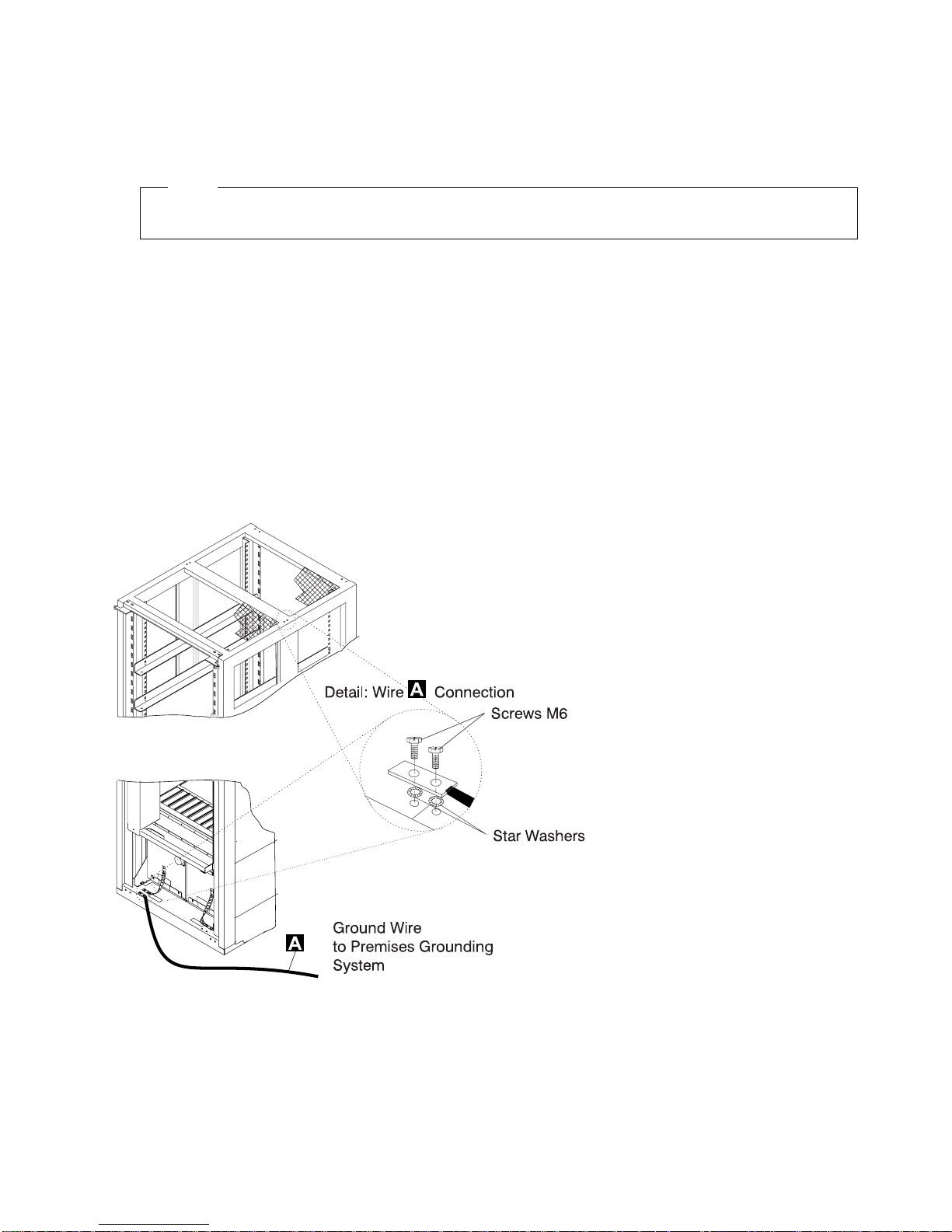
For the 2220-300 and the 2220-500, an additional ground wire .A/ is also used.
The 2220-501 is connected to the 2220-500 via a ground wire .B/ (see Figure 0-2 on
page xx).
1) 2220 Model 300 and 500 Ground Wire
Check the presence of ground wire .A/ on the 2220 (see Figure 0-1).
The ground wire .A/ can also be installed on the top of the 2220 Model 300/500 frame if
necessary.
Figure 0-1. 2220 Ground Wire A
General and Product Safety xix
Page 22
Notes:
a) .A/ Wire (PN 80G3815)
b) Screws (PN 43G3084)
c) Star washers (PN 1622348)
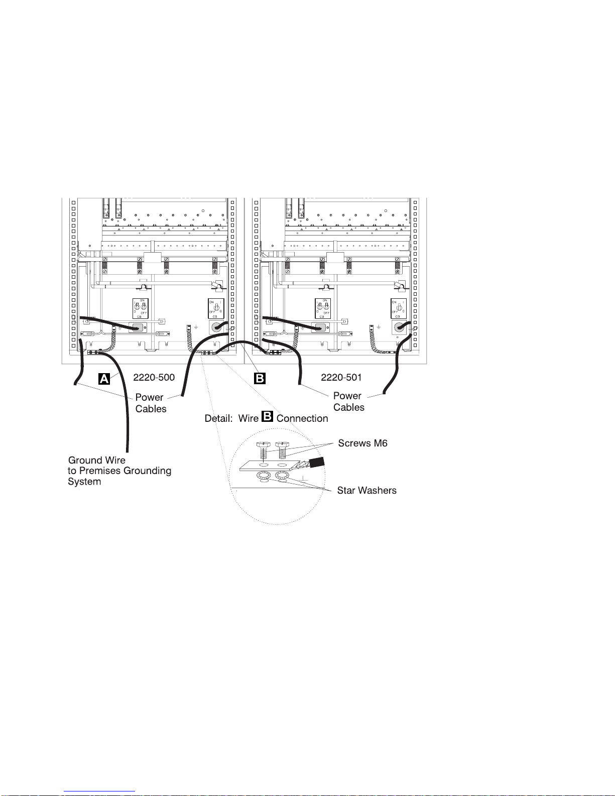
2) 2220 Model 501 Ground Wire
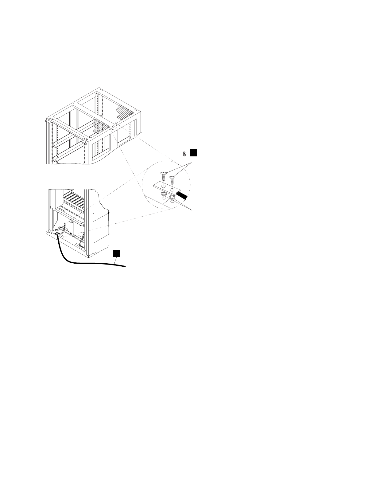
When a 2220-501 is installed, check the presence of ground wire .B/ between the
2220-500and the 2220-501 (see Figure 0-2).
Figure 0-2. 2220 Ground Wire B Between 2220-500and 2220-501
Notes:
a) .B/ Wire (PN 80G3715)
b) Screws (PN 43G3084)
c) Star washers (PN 1622348)
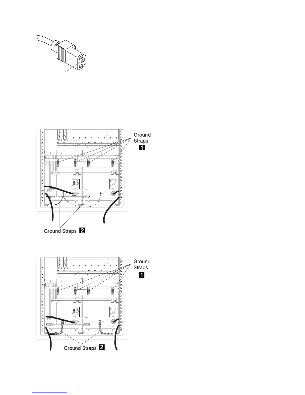
3) ac/dc Power Cable Ground Wire
Check the mainline ac/dc power cable for damaged or burned pins and broken insulation
on all units.
Measure the resistance of the disconnected mainline ac/dc power cable from ground pin
on one end to the ground pin on the other end.
The reading should be 0.1 ohm or less.
xx 2220 Models 300, 500, and 501: Service Guide
Page 23
Ground Pin
Figure 0-3. 2220 Ground Pin on Mainline ac/dc Power Cable
b. Internal Grounding in the 2220
Check that:
Electrical continuity is assured within each rack, between the rack ground and the installed
power supplies via ground straps .1/.
Figure 0-4. 2220 Ground Straps (Former Machine)
Figure 0-5. 2220 Ground Straps
General and Product Safety xxi
Page 24
Electrical continuity is assured, between the rack ground and the power supply receptacle via
ground straps .2/.
Electrical continuity is assured, between the rack ground and the Line Connection Box (LCB),
if LCBs are present. This operation must be performed before any network connection (see
Figure 0-6).
c. Grounding of Line Connection Boxes (LCBs) not Installed in 2220
Check that electrical continuity is assured between the LCB housing and the premises grounding
system.
There are two ways to insure a proper grounding of the LCB, according to where it is installed:
1) Grounding is insured by the four screws (which secure the LCB on the rack) if the frame of the
rack is connected to the premises ground system.
Figure 0-6. LCB Grounding via Screws
2) Grounding is insured by a wire connected from the LCB to the premises ground system, when
the LCB is installed in a rack with frame not connected to the premises ground system.
Screws for
Grounding
Front View
xxii 2220 Models 300, 500, and 501: Service Guide
Page 25
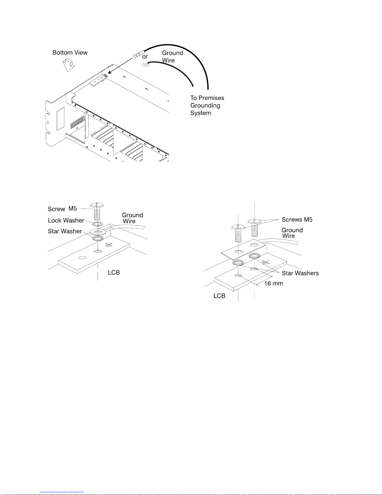
Figure 0-7. LCB Grounding via Ground Wire
Ground Wire Connection on LCB
There are two ways to secure the ground wire on the LCB.
Figure 0-8. Standard Connection
Figure 0-9. Bellcore Specification Connection
This operation must be performed before any network connection.
Note: All the previous checking should indicate 0.1 ohm or less.
d.Building Grounding
Check there is less than 1 V ac between the metal housings of plugs, connectors,
receptacles, and so on, and any grounded point in the building. This can be any grounded
metal structure, such as the stanchions of a raised floor (if they are electrically connected
to building ground), a metal water pipe, building steel, and so on.
Notes:
1) When probing a painted metal part, be sure that the meter probe tip penetrates the paint.
2) Also check the plugs metal housing of incoming cables.
4. Circuit Breaker and Circuit Protector Rating
Each power box has one circuit breaker (CB) and six circuit protectors (CPs).
General and Product Safety xxiii
Page 26

Power Box CB/CP Rating
ACDC / DC48 CP1 to CP5 CP6 8A dc 4A dc
ACDC CB 12A ac
DC48 CB 40A dc
The CB and all CPs are in the sealed ACDC or DC48 power box.
Check the PN on the input power box, refer to the parts catalog. In the case of a discrepancy, contact
your support structure.
5. Input Power Voltage
Two types of power boxes can be installed on 2220 family machines:
ACDC Power: The input power voltage is from an ac voltage (200-240 V and 50 or 60 Hz).
DC48 Power: The input power voltage is from a dc source (39-60 V).
In the 2220 family, the ACDC and DC48 power boxes can be mixed on each machine model.
6. Power ON Indicators
Ask the customer to:
a. Connect the power cords to the customer's energy supplies
b. Put the CBs ON
c. Turn the power ON/STANDBY switch to ON (position on the control panel).
Once the 2220 is powered ON, using the following table, check the status of each element.
Element Status
Control Panel The green LED(s) POWER SUPPLY 1 and 2 on the 2220control panel are ON (if you
have two power boxes installed in the 2220).
The APC green LED blinks during power on self test (POST), and then comes ON.
The yellow LEDs FAN BOX and ALARM are OFF.
ACDC Power The green LEDs AC GOOD and DC/HW GOOD are ON.
The yellow LED BATTERY EXCHANGE REQUIRED is OFF.
DC48 Power (if
installed on
your machine)
On top of
Modules
installed in
your 2220
The green LED (DC/HW GOOD) is ON.
Green LEDs are ON.
7. Emergency Power OFF of the Board
Turn the power ON/STANDBY switch to STANDBY (position on the control panel) and check that:.
The POWER SUPPLY 1 and 2 LEDs on the control panel are OFF.
The fans are stopped.
8.Cooling
Be sure that all the modules and dummy modules are properly installed to ensure proper cooling.
xxiv 2220 Models 300, 500, and 501: Service Guide
Page 27

Sicherheitsüberprüfungen
Einführung
Die Sicherheit des 2220sollte in folgenden Fällen überprüft werden:
Bei einer Prüfung nach Absprache mit IBM
Wenn eine IBM Wartung angefordert wird, und in der letzten Zeit keine Wartung durch IBM
durchgeführt worden war.
Wenn Änderungen am Gerät oder Anschlüsse überprüft werden.
Wenn Änderungen am Gerät vorgenommen worden sind, die möglicherweise die Sicherheit
beeinträchtigen.
Wenn bei der Überprüfung ein unzureichender Sicherheitszustand festgestellt wird, müssen die Mängel
behoben werden, bevor IBM das Gerät wartet.
Anmerkung: Für die Behebung von Sicherheitsmängeln ist der Besitzer des Geräts verantwortlich.
Folgende Bereiche und Funktionen des 2220 werden im folgenden geprüft:
1. Äußere Abdeckungen
2. Sicherheitsaufkleber
3. Erdung
4. Sicherungsautomat und Überstromschutzschalter
5. Netzeingangsspannung
6. Betriebsanzeigen
7. Notausschalter der Platine
8. Kühlung
Vor der Prüfung der oben genannten Punkte muß die Stromzufuhr folgendermaßen unterbrochen
werden:
Am 2220 die Hauptsicherungsautomaten öffnen.
Alle im Einschub des 2220 installierten Geräte oder damit verbundenen Geräte ausschalten.
Stromversorgung beim Kunden ausschalten.
Netzkabel und Schutzleiter .A/ am 2220 nicht entfernen, damit die Erdung gewährleitet ist (siehe
Figure 0-10 on page xxvii).
General and Product Safety xxv
Page 28

1.Äußere Abdeckungen
Prüfen, ob
alle äußeren Abdeckungen am 2220 angebracht sind.
die Einschübe genügend Raum und Zugänge für Wartungsarbeiten haben, wenn die äußeren
Abdeckungen geöffnet sind.
Alle äußeren Abdeckungen für weitere Überprüfungen offen lassen.
2.Sicherheitsaufkleber
Prüfen, ob
sich alle Sicherheitsaufkleber an den mit Buchstaben gekennzeichneten Stellen befinden, wie
unter “Safety Label Locations” on page xl beschrieben.
jeder Aufkleber dem richtigen Modell entspricht, wie anhand der Buchstaben unter “Safety Label
Identifications” on page xliv angegeben ist.
Für die Prüfung der Aufkleber am ACDC-Eingang (Gleichstrom-Wechselstrom) und/oder
DC48-Eingang (48Volt Gleichstrom) und an der Batterie (sofern vorhanden) müssen Sie diese
Funktionseinheiten entfernen. Unter Chapter 6, “2220 FRU Exchange” on page 6-1 sind ausführliche
Anweisungen zu finden.
3.Erdung
a. Schutzleiterverbindung von 2220, NAS, Bildschirm und Modem an das Erdungssystem des
Gebäudes
Der elektrische Durchgang zwischen Gehäuseerdung und dem Erdungssystem des Gebäudes
wird über die Netzkabel sichergestellt.
Beim 2220-300 und 2220-500 wird zusätzlich ein Schutzleiter .A/ verwendet.
Der 2220-501 wird über ein Schutzleiter .B/ an den 2220-500 angeschlossen (siehe
Figure 0-11 on page xxviii).
xxvi 2220 Models 300, 500, and 501: Service Guide
Page 29
1) Schutzleiter des 2220 Modell 300 und 500
Prüfen, ob am 2220 ein Schutzleiter .A/ vorhanden ist (siehe Figure 0-10).
Der Schutzleiter .A/ kann gegebenenfalls auch oben am Rahmen des 2220 Modell 300/500
installiert sein.
Detail: Kabelanschu
Schutzleiter an
A
Erdungssystem
des Gebäudes
Figure 0-10. Schutzleiter A am 2220
Notes:
a) Kabel .A/: (Teilenummer 80G3815)
b) Schrauben: (Teilenummer 43G3084)
c) Zahnscheiben: (Teilenummer 1622348)
A
Schrauben M6
Zahnscheiben
General and Product Safety xxvii
Page 30

2) Schutzleiter am 2220 Modell 501
Wenn ein 2220-501 installiert ist, prüfen, ob sich ein Schutzleiter .B/ zwischen 2220-500und
2220-501 befindet. (siehe Figure 0-11).
A
Schutzleiter an Erdungssystem
des Gebäudes
Figure 0-11. 2220 Schutzleiter B zwischen 2220-500 und 2220-501
3) Schutzleiter des Netzkabels
2220-500 2220-501
Netzkabel
Detail: Kabelanschu
Notes:
a) Kabel .B/ (Teilenummer 80G3715)
b) Schrauben (Teilenummer 43G3084)
c) Zahnscheiben (Teilenummer 1622348)
Hauptnetzkabel aller Geräte auf beschädigte oder verbrannte Kontakte und beschädigte
Isolierung prüfen.
B
Netzkabel
B
2
Schrauben M6
Zahnscheiben
Den Widerstand des nicht angeschlossenen Hauptnetzkabels zwischen dem
Schutzleiterkontakt am einen und dem Schutzleiterkontakt am anderen Ende messen.
Der Widerstand darf maximal 0,1 Ohm betragen.
xxviii 2220 Models 300, 500, and 501: Service Guide
Page 31

Schutzleiterkontakt
Figure 0-12. Schutzleiterkontakt am Hauptnetzkabel des 2220
b. Interne Erdung im 2220
Prüfen, ob
der elektrische Durchgang innerhalb eines jeden Gehäuses über Schutzleiter .1/ zwischen
dem Gehäuseschutzleiteranschluß und den installierten Netzteilen gewährleistet ist.
Schutzleiterverbindungen
1
Schutzleiterverbindungen
1
Schutzleiterverbindungen
Figure 0-13. Schutzleiter am 2220 (vorheriges Modell)
der elektrische Durchgang über Schutzleiter .2/ zwischen dem Gehäuseschutzleiteranschluß
und dem Schutzleiterkontakt gewährleistet ist.
der elektrische Durchgang zwischen dem Gehäuseschutzleiteranschluß und dem
Verteilerkasten, sofern vorhanden, gewährleistet ist. Dieser Schritt muß vor dem Anschluß von
Signalkabeln erfolgen (siehe Figure 0-15 on page xxx).
c. Erdung der nicht im 2220 installierten Verteilerkästen
Prüfen, ob der elektrische Durchgang zwischen dem Gehäuse des Verteilerkasten und dem
Erdungssystem des Gebäudes gewährleistet ist.
Je nach Installationsort kann der Verteilerkasten auf zweierlei Arten geerdet werden:
1) Erdung über die vier Schrauben (mit denen der Verteilerkasten am Gehäuse befestigt ist), falls
der Gehäuserahmen mit dem Erdungssystem des Gebäudes verbunden ist (siehe Figure 0-15
on page xxx).
2
Schutzleiterverbindungen
Figure 0-14. 2220 Schutzleiter
2
General and Product Safety xxix
Page 32

Schrauben
für Erdung
Vorderansicht
Figure 0-15. Erdung des Verteilerkastens über Schrauben
2) Erdung über ein Kabel, das den Verteilerkastens mit dem Erdungssystem des Gebäudes
verbindet, wenn der Verteilerkasten in einem Gehäuse installiert ist, dessen Rahmen nicht mit
dem Erdungssystem des Gebäudes verbunden ist.
Unteransicht
oder
Schutzleiter
an Erdungssystem
des Gebäudes
Figure 0-16. Erdung des Verteilerkastens über Schutzleiter
xxx 2220 Models 300, 500, and 501: Service Guide
Page 33

Schutzleiteranschluß am Verteilerkasten
Der Schutzleiter kann auf zweierlei Arten am Verteilerkasten angeschlossen werden.
Schraube
M5
Sicherungsscheibe
Zahnscheibe
Verteilerkasten
Figure 0-17. Standardanschluß
Dieser Schritt muß vor dem Anschluß jeglicher Signalkabel erfolgen.
Anmerkung: Bei allen vorherigen Prüfungen sollten maximal 0,1 Ohm gemessen werden.
d. Erdung des Gebäudes
Sicherstellen, daß zwischen den Metallgehäusen von Steckern, Buchsen usw. und jeder
geerdeten Stelle im Gebäude eine Wechselspannung von weniger als 1 V anliegt. Dies kann
jedes geerdete Metallteil sein, wie z. B. die Stützen eines Doppelbodens (wenn sie mit dem
Gebäudeerder verbunden sind), ein metallisches Wasserrohr, Baustahl usw.
Anmerkung:
Schutzleiter
Schrauben M5
Schutzleiter
Zahnscheiben
16 mm
Verteilerkasten
Figure 0-18. Anschluß nach Bellcore-Norm
1) Beim Prüfen an einem lackierten Metallteil sicherstellen, daß die Prüfspitze die Farbe
durchbohrt.
2) Auch Metallgehäuse der anzuschließenden Kabel überprüfen.
4. Sicherungsautomat und Überstromschutzschalter
Jeder Energieversorgungsblock verfügt über eine Sicherung und sechs Sicherungsschalter.
Sicherungsautomat
Energieversorgungsblock
ACDC, DC48 Überstromschutzschalter 1 bis 5
ACDC Sicherungsautomat 12 A-Wechselstrom
DC48 Sicherungsautomat 40 A-Gleichstrom
Überstromschutzschalter Nennstrom
8 A Gleichstrom 4 A Gleichstrom
Überstromschutzschalter 6
Der Sicherungsautomat und die Überstromschutzschalter befinden sich in dem versiegelten
Energieversorgungsblock (ACDC bzw. DC48).
Die Teilenummer des Eingangsenergieversorgungsblocks prüfen, siehe Teilekatalog. Falls
Unstimmigkeiten auftreten, an das KD-Unterstützungspersonal wenden.
5.Eingangsspannung
In die Geräten der 2220-Familie können zweierlei Energieversorgungsblöcke installiert werden.
ACDC: Bei der Eingangsspannung handelt es sich um Wechselspannung (200-240 V, 50 oder 60
Hz).
General and Product Safety xxxi
Page 34

DC48: Bei der Eingangsspannung handelt es sich um Gleichspannung (39-60 V).
Bei der 2220-Familie können gleichzeitig der ACDC- und der DC48-Energieversorgungsblock in
jedem Modell installiert sein.
6.Betriebsanzeigen
Den Kunden um folgendes bitten:
a. Netzkabel an das Netz des Kunden anschließen.
b. Sicherungen EINSCHALTEN.
c. Den Betriebsschalter des Geräts auf EIN stellen. (Position am Bedienungsfeld).
Sobald der 2220 eingeschaltet ist, anhand der folgenden Tabelle den Status eines jeden Elements
prüfen.
Element Status
Bedienungs-
feld
ACDC Die grünen LEDs (AC GOOD und DC/HW GOOD) LEUCHTEN.
DC48 (sofern
installiert)
Oben auf den
im 2220
installierten
Modulen
Die grünen LEDs (STROMVERSORGUNG 1 und 2) am Bedienungsfeld des
2220LEUCHTEN (wenn im 2220 zwei Energieversorgungsblöcke installiert sind).
Die grüne LED APC blinkt während des Selbsttests beim Einschalten und LEUCHTET
dann dauerhaft.
Die gelben LEDs (VENTILATOR und ALARM) LEUCHTEN NICHT.
Die gelbe LED (BATTERY EXCHANGE REQUIRED) LEUCHTET NICHT.
Die grüne LED (DC/HW GOOD) LEUCHTET.
Grüne LEDs LEUCHTEN.
7. Notausschalter der Platine
Den Betriebsschalter auf BEREITSCHAFT stellen. (Position am Bedienungsfeld) und sicherstellen,
daß:
die LEDs STROMVERSORGUNG 1 und 2 am Bedienungsfeld NICHT LEUCHTEN.
die Lüfter nicht laufen.
8.Kühlung
Prüfen, ob alle Module und Dummy-Module richtig installiert sind, damit eine ausreichende Kühlung
gewährleistet ist.
xxxii 2220 Models 300, 500, and 501: Service Guide
Page 35

General and Product Safety xxxiii
Page 36

xxxiv 2220 Models 300, 500, and 501: Service Guide
Page 37

General and Product Safety xxxv
Page 38

xxxvi 2220 Models 300, 500, and 501: Service Guide
Page 39

General and Product Safety xxxvii
Page 40

xxxviii 2220 Models 300, 500, and 501: Service Guide
Page 41

General and Product Safety xxxix
Page 42

Safety Label Locations
In the following figures, labels are designated by letters. A particular wording
corresponds to each letter (see “Safety Label Identifications” on page xliv).
A
Figure 0-19. Safety Labels on Internal Front Cover
B
C
Figure 0-20. Safety Labels on Internal Rear Board Cover
xl 2220 Models 300, 500, and 501: Service Guide
Page 43

D
Figure 0-21. Safety Labels on Internal Front Board Cover
R
Figure 0-22. Safety Labels on Rear of the 2220 Rack
General and Product Safety xli
Page 44

Figure 0-23. Safety Label on LCB
S
G
J2
J2
J3
J4
J5
J4
J3
J5
J N
J
Safety Labels on DC48 Power (Old Model)
Safety Labels on DC48 Power (New Model)
xlii 2220 Models 300, 500, and 501: Service Guide
Page 45

G
H
H
K
J3
J4
J5
P
Safety Labels on ACDC Power (Old Model)
K
J2
M1
MOV
J5
M2
J3
J4
Safety Labels on ACDC Power (New Model)
Figure 0-24. Safety Labels on Battery
General and Product Safety xliii
E
L
Page 46

Safety Label Identifications
LABEL A
ATTENTION
POUR COUPER COMPLETEMENT
LE COURANT DANS LE RACK,
METTRE LES CBs EN POSITION OFF,
ET DECONNECTER TOUS LES CORDONS
D’ALIMENTATION A L’ARRIERE
CAUTION
TO REMOVE POWER COMPLETELY
IN THE RACK TURN ALL CBs OFF,
THEN DISCONNECT ALL
POWER CORDS AT THE REAR
I
ON
1
O
OFF
2
Figure 0-25. Power Label (PN 57G7919 and PN 57G7976)
Note: Depending on the machine configuration you may have one or two power
supplies installed. Based on that, one or two power cords may be present.
Only a part of this label is shown. This label installed on the machine is
translated into 14 languages.
LABEL B
<
60 V dc
240 V A
>
LABEL C
<
>
LABEL D
60 V dc
<
>
240 V A
Figure 0-26. Board Labels (PN 57G7920)
xliv 2220 Models 300, 500, and 501: Service Guide
60 V dc
240 V A
<
>
<
>
60 V dc
240 V A
60 V dc
240 V A
<
>
60 V dc
240 V A
<
>
60 V dc
240 V A
<
>
60 V dc
240 V A
<
>
60 V dc
240 V A
<
>
60 V dc
240 V A
60 V dc
<
>
240 V A
Page 47

LABEL E
< 60 V dc
> 240 V
A
LABEL G
DO NOT OPEN
NE PAS OUVRIR
NICHT ÖFFNEN
NIET OPENEN
NON APRIRE
NO ABRIR
~
NAO ABRIR
LABEL P
-
200
-
8
/
50
Figure 0-27. Other Labels
LABEL H
LABEL J
240 V
6.3A
60 Hz
>18Kg
SAFETY EXTRA LOW VOLTAGE INPUT ONLY
ALIMENTATION TRES BASSE TENSION DE
SECURITE SEULEMENT
NUR AN SICHERHEITS-KLEINSPANNUNG ANSCHLIESSEN
LABEL L
SEALED LEAD
ACID BATTERY
BATTERY MUST
BE RECYCLED
Figure 0-28. Labels Used for Europe, Taiwan, and Brazil (PN 57G7959)
General and Product Safety xlv
+
Pb
LABEL K
CONTAINS
SEALED LEAD
ACID BATTERY
BATTERY MUST
BE RECYCLED
+
Pb
Page 48

LABEL L
Pb
SEALED LEAD
ACID BATTERY
BATTERY MUST
BE RECYCLED
LABEL K
Figure 0-29. Labels Used for Other Countries (PN 57G7958)
LABEL N
R
NRTL/C LEVEL 5
CODE: 3557-99-100
INPUT: -48V(60V...-39V) - - -
OUTPUT:
CP1-CP5: -48V - - - 12A (-60V. . . -36V - - -)
TOTAL OUTPUT POWER:
1550W MAXIMUM
LR 56325
MagneTek S.p.A.
MADE IN ITALY
43A MAXIMUM
CP6: -48V - - - 6A (-60V . . . -36V - - -)
Pb
CONTAINS
SEALED LEAD
ACID BATTERY
BATTERY MUST
BE RECYCLED
Figure 0-30. Power Rating Label for DC48
LABEL M1 and M2
R
NRTL/C LEVEL 5
LR 56325
MagneTek S.p.A.
MADE IN ITALY
CODE: 3547-99-100
OPERATIONFROM MAINS
INPUT:200-240 V 50-60Hz 9.1 A
OUTPUT:
CP1-CP5: -48V ---10A
CP6: -48V - - - 6A
TOTAL OUTPUT POWER: 1350W MAXIMUM
OPERATIONFROM BATTERY BACK-UP UNIT
OUTPUT:-59V . . . -36V - - -
TOTAL OUTPUT POWER: 675 W MAXIMUM
Figure 0-31. Power Rating Label for ACDC
10
OK
OK
HP2600 Vdc
M1
M2
xlvi 2220 Models 300, 500, and 501: Service Guide
Page 49

LABEL R
HIGH LEAKAGE CURRENT
Permanent ground connection
is mandatory
before connecting power supplies
and making network connections.
Figure 0-32. Label for 2220 Rack (PN 80G3929)
LABEL S
HIGH LEAKAGE CURRENT
Permanent ground connection
is mandatory
before network connections.
Figure 0-33. Label for LCB (PN 80G3928)
General and Product Safety xlvii
Page 50

xlviii 2220 Models 300, 500, and 501: Service Guide
Page 51

About this Manual
Aim of this Manual
The service guide gives the service representative the information needed to:
Exchange all the FRUs of the 2220
Run diagnostics on the 2220.
It is expected that the 2220 problem determination has been done by the remote
support center (RSC).
Who Should Read this Manual
The person using this manual should be:
Trained to service the 2220.
Familiar with the configuration and operation of the 2220.
Familiar with the configuration and operation of the Nways Switch
administration station.
The intended audience for this manual is Product-Trained Customer Engineers
(PT-CE). The Product-Support Customer Engineer (PST-CE) is also expected to
refer to the manual when required to perform the same tasks as the PT CE.
How this Manual is Organized
This manual is organized as follows:
Safety information is at the beginning of this book.
Chapter 1 Gives page number references for starting various service and
troubleshooting procedures.
Chapter 2 Gives an introduction and an overview of the 2220.
Chapter 3 Gives an overview of the functions available on Nways Switch
administration station, and how to invoke some of them.
Chapter 4 Gives the diagnostics available for 2220, and how to invoke
these diagnostics.
Chapter 5 Gives the MAPs to be used for problem determination on the
2220.
Chapter 6 Gives the procedure to exchange the FRU on 2220.
Appendixes A to E Give:
Copyright IBM Corp. 1998, 1999 xlix
Schematics
Maintenance aids
2220 Power Consumption
Parts catalog
Page 52

Part number index
Appendix X Gives:
Bibliography
Glossary
Index.
l 2220 Models 300, 500, and 501: Service Guide
Page 53

Chapter 1. START - Finding a Service Procedure
Note: The 2220 models 300, 500, and 501 are installed in a 37 U1 rack or 29 U rack. In this manual
the 2220 models are shown installed in a 37 U rack. The 29 U rack is shown only when the
procedures are different from the 37 U rack.
Select the first entry point that fits your situation.
If You Have Description Go to
GENERAL
SYMPTOM
MAINTENANCE
ACTION
MISCELLANEOUS
INFORMATION
2220 power symptom “MAP 0500: 2220 Basic Verification” on page 5-2.
2220 control panel symptom “MAP 0500: 2220 Basic Verification” on page 5-2.
Nways Switch administration
station symptom
2220 Basic verification “MAP 0500: 2220 Basic Verification” on page 5-2.
2220 FRU to exchange Chapter 6, “2220 FRU Exchange” on page 6-1.
Nways Switch administration
station FRU to exchange
Run diagnostics on the 2220 or “Service Operation via Nways Switch
2220 Service operation via the
Nways Switch administration
station
Run diagnostics on the Nways
Switch administration station
Test the Nways Switch
administration station links
2220 In broadband network “Typical Broadband Network Based on 2220” on
2220 model overview “2220 Models” on page 2-2.
Nways Switch administration
station windows overview
2220 control panel functions “Nways Switch Administration Station Windows
2220 schematics Appendix A, “Schematics” on page A-1.
2220 parts catalog Appendix D, “Parts Catalog” on page D-1.
Refer to the Nways Switch administration service
guide.
Refer to the Nways Switch administration service
guide.
Administration Station” on page 1-2.
“Service Operation via Nways Switch
Administration Station” on page 1-2.
Refer to the Nways Switch administration service
guide.
Refer to the Nways Switch administration service
guide.
page 2-1.
“Nways Switch Administration Station Windows
Overview” on page 3-5.
Overview” on page 3-5.
1
U means EIA Units (U-units)
Copyright IBM Corp. 1998, 1999
1-1
Page 54

Service Operation via Nways Switch Administration Station
Service Action Go to
Logon to the 2220 (Local) “How to Start on the Local 2220” on page 3-1
Logon to the 2220 (Remote) “How to Logon to the Remote 2220” on page 3-1
Display the Nways Switch
configuration
Display the TCP/IP addresses “How to Find a TCP/IP Address” on page 3-20
Display the Nways Switch Control
Program Inventory
Display the test event desk “How to Display the Test Event Desk” on page 3-18
Display CMIP Status “How to Display the CMIP Status” on page 3-8
Display the Alarm Desk “How to Display the Alarm Desk” on page 3-11
Run diagnostics on the 2220 Chapter 4, “2220 Diagnostics” on page 4-1.
Run diagnostics on the Nways Switch
administration station
Test the link between the Nways
Switch administration station and the
NSC
Test the Nways Switch administration
station links
Find machine and module power
consumption
Emergency trunck unlock “How to Perform the Emergency Trunk Unlock” on page 3-26.
Removing a line or trunk cable on
operational 2220
“How to Display the Nways Switch Configuration” on page 3-13
“How to Display the Nways Switch Control Program Inventory and
Level” on page 3-22
Refer to the Nways Switch administration service guide.
Refer to the Nways Switch administration service guide.
Refer to the Nways Switch administration service guide.
Appendix C, “2220 Power Consumption” on page C-1.
“How to Remove a Line or Trunk Cable” on page 3-24.
1-2 2220 Models 300, 500, and 501: Service Guide
Page 55

Chapter 2. Introduction / Overview
Typical Broadband Network Based on 2220
To IBM Network
Support Center
(Via Modem)
User
Premises
User
Premises
2220
Centralized
Configuration
Database
OS/2 Workstation
with Nways Switch
Configuration Tool
Ethernet LAN
Entry
point
2220
Via
2220
Network Management Station
and
Change Control Server
NetView for AIX with
Nways Enterprise Manager
and
NetView DM for AIX
Broadband
Network
2220
User
Premises
Copyright IBM Corp. 1998, 1999 2-1
2220
Nways Switch
Adminstration
Station
User
Premises
Customer
Remote Console
(via Modem or
Ethernet LAN)
Page 56

2220 Models
This manual covers the following 2220 models:
2220 Model 300 (low-end unit)
2220 Model 500 (base unit)
2220 Model 501 (expansion to 2220 Model 500)
2-2 2220 Models 300, 500, and 501: Service Guide
Page 57

2220 Control Panel Functions
FAN BOX
1
2
APC RESET
ALARM
A P C
POWER SUPPLY
1
2
The front panel contains:
The power ON/STANDBY switch, which is used to power ON (position on the
control panel) or STANDBY (position on the control panel) the 2220 (see
note).
The APC RESET button, which resets the APC (but does not disturb the data
traffic).
Six LEDs that indicate different status:
POWER SUPPLY 1 and 2 Each of these two green LEDs reflects the status
of one power supply (1 or 2). Each LED is ON
when the associated power supply is ON.
APC This green LED is ON when the alarm and power
control (APC) module inside the 2220is running
error free. It is blinking during the power on self
test (POST), or when an adapter has been
disabled.
ALARM This yellow LED is ON when an error has been
detected in the 2220.
FAN BOX 1 and 2 Each of these two yellow LEDs reflects the status
of one FAN box. They are ON as soon a FAN
problem has been detected.
Note: When the power ON/STANDBY switch is on the STANDBY position on
the control panel), the 2220 board is powered OFF while the power-supplies
are still in Stand-by mode (energized).
Chapter 2. Introduction / Overview 2-3
Page 58

2-4 2220 Models 300, 500, and 501: Service Guide
Page 59

Chapter 3. Nways Switch Administration Station Functions
How to Start on the Local 2220
To log on:
1. Be sure that the 2220 and the Nways Switch administration station are
powered ON.
2. In the Nways Switch Desktop window, select the desired icon by clicking on
the left button of the mouse (left button is used to select an icon or resource,
and the right button displays the associated menu).
Figure 3-1. Nways Switch Desktop Display
3. For detail refer to the “Nways Switch Administration Station Windows Overview”
on page 3-5.
How to Logon to the Remote 2220
When the Nways Switch administration station is powered ON and initialized the
Nways Switch Desktop window is displayed:
1. Double click on the Nways Switch Services icon.
2. In the Nways Switch Services window, double click on the Nways Switch
Resource Control (Remote) icon.
Copyright IBM Corp. 1998, 1999 3-1
Page 60

The Logon Remote NAS window is displayed.
3. Enter the requested information then click on Logon.
4. The following windows are displayed. Click on OK on each of them.
3-2 2220 Models 300, 500, and 501: Service Guide
Page 61

The Nways Switch Resource Control window of the remote NAS is displayed.
5. In the Nways Switch Resource Control window, click on View then on View,
Expanded Tree View.
6. Wait until all icons are displayed.
Chapter 3. Nways Switch Administration Station Functions 3-3
Page 62

Figure 3-2. Example of Expanded Tree
7. Perform the desired action on the window.
3-4 2220 Models 300, 500, and 501: Service Guide
Page 63

Nways Switch Administration Station Windows Overview
When the Nways Switch administration station is powered ON and initialized the
Nways Switch Desktop window is displayed.
1. Double click on the Nways Switch Services icon.
2. In the Nways Switch Services window, double click on the Nways Switch
Resource Control (Local) icon.
3. Click on OK in the Product Information window.
4. In the Nways Switch Resource Control window, click on View, Expanded
Tree View.
5. Wait until all icons are displayed.
Chapter 3. Nways Switch Administration Station Functions 3-5
Page 64

Figure 3-3. Example of Expanded Tree
6. In the Node Resources window, using the right key on the mouse, click on the
icon of the resource that you want to select, then using the left button on the
mouse, click again on the resource to display a popup window with all options
available for the resource.
3-6 2220 Models 300, 500, and 501: Service Guide
Page 65

Figure 3-4. Example of Options Available for a Selected Resource
Figure 3-5. Example of Options Available for a Switch
Chapter 3. Nways Switch Administration Station Functions 3-7
Page 66

How to Display the CMIP Status
When the Nways Switch administration station is powered ON and initialized the
Nways Switch Desktop window is displayed.
1. Double click on the Nways Switch Services icon.
2. In the Nways Switch Services window, double click on the Nways Switch
Resource Control (Local) icon.
3. In the Nways Switch Resource Control window, click on View, Expanded
Tree View.
4. Wait until all icons are displayed.
3-8 2220 Models 300, 500, and 501: Service Guide
Page 67

Figure 3-6. Example of Expanded Tree
5. In the Node Resources window, using the right key on the mouse, click on the
icon of the resource that you want to select. A popup window with all options
available for the resource is displayed.
Chapter 3. Nways Switch Administration Station Functions 3-9
Page 68

6. Click on the Open the on the Status option.
The Display CMIP Status window is displayed with the current status
highlighted.
3-10 2220 Models 300, 500, and 501: Service Guide
Page 69

How to Display the Alarm Desk
When the Nways Switch administration station is powered ON and initialized the
Nways Switch Desktop window is displayed.
1. Double click on the Nways Switch Services icon.
2. In the Nways Switch Services window, double click on the Nways Switch
Alarm Desk icon.
The Alarm Desk window is displayed.
3. By clicking on the Search option in the menu bar you have all the facilities for
selecting a specific alarm.
Chapter 3. Nways Switch Administration Station Functions 3-11
Page 70

Figure 3-7. Search Options in the Alarm Desk Window
3-12 2220 Models 300, 500, and 501: Service Guide
Page 71

How to Display the Nways Switch Configuration
When the Nways Switch administration station is powered ON and initialized the
Nways Switch Desktop window is displayed.
1. In the Nways Switch Desktop window, double click on the Nways Switch
Configuration icon.
2. Double click on the Nways Switch Configuration Tool icon.
3. A Nways Switch Configuration Tools window is displayed.
4. Double click on the rack icon that you want to know the configuration.
Chapter 3. Nways Switch Administration Station Functions 3-13
Page 72

5. Different icons are displayed. Double click on the selected icon. According to
the icon selected you have different window displayed. For example if you click
on the Rack A the following window is displayed.
6. If you double click on the LIC511 the following window is displayed.
3-14 2220 Models 300, 500, and 501: Service Guide
Page 73

7. Double click on the LCB 1 Expansion icon the following window is displayed.
8. Double click on the 29 line icon. The following window is displayed showing the
line configuration
Chapter 3. Nways Switch Administration Station Functions 3-15
Page 74

9. From the rack configuration window you also can select an adapter.
3-16 2220 Models 300, 500, and 501: Service Guide
Page 75

10. Double click on a adapter icon the following window is displayed showing the
adapter configuration.
Chapter 3. Nways Switch Administration Station Functions 3-17
Page 76

How to Display the Test Event Desk
When the Nways Switch administration station is powered ON and initialized the
Nways Switch Desktop window is displayed.
1. Click on the Nways Switch Services icon.
2. In the Nways Switch Services window, click on the Nways Switch Resource
Control (Local) icon.
3. In the Nways Switch Resource Control window, click on View and then on
the Test Event Desk option.
The following window is displayed.
3-18 2220 Models 300, 500, and 501: Service Guide
Page 77

Chapter 3. Nways Switch Administration Station Functions 3-19
Page 78

How to Find a TCP/IP Address
The Nways Switch Installation Program is used to customize the IP parameters
from the data imported with the configuration file.
1. Double click on the Nways Switch Installation icon.
Figure 3-8. Nways Switch Desktop Window
2. Double click on the Nways Switch Installation Program icon.
Figure 3-9. Nways Swith Installation Window
3. Select option 5 and press Enter.
Figure 3-10. Installation Program Main Menu
4. In the window displayed search for the required TCP/IP address. See
Figure 3-11 on page 3-21.
3-20 2220 Models 300, 500, and 501: Service Guide
Page 79

Figure 3-11. Example of TCP/IP address
Chapter 3. Nways Switch Administration Station Functions 3-21
Page 80

How to Display the Nways Switch Control Program Inventory and
Level
When the Nways Switch administration station is powered ON and initialization is
completed the following window is displayed:
1. Double click on the Nways Switch Services icon.
2. In the Nways Switch Services window, double click on the Nways Switch
Control Program Inventory icon.
3. A Nways Switch Control Program Software Inventory window is displayed
with the file name and the date of changes.
3-22 2220 Models 300, 500, and 501: Service Guide
Page 81

Figure 3-12. Example of Nways Switch Control Program Software Inventory
Chapter 3. Nways Switch Administration Station Functions 3-23
Page 82

How to Remove a Line or Trunk Cable
Important
Before removing a line or trunk cable attached to an active LIC, lock the
corresponding line or trunk using the following procedure.
The following procedure is an example of how to Lock a Line. The window
contents may be different on your screen.
When the Nways Switch administration station is powered ON and initialized the
Nways Switch Desktop window is displayed.
1. Click on the Nways Switch Services icon.
2. In the Nways Switch Services window, click on the Nways Switch Resource
Control (Local) icon.
3. In the Nways Switch Resource Control window, using the left or bottom
button on the mouse, click on the
right or top button on the mouse, click again on the resource.
Line
that you want to lock. Then using the
4. The following window is displayed. Click on the Lock option.
3-24 2220 Models 300, 500, and 501: Service Guide
Page 83

5. A warning Disruptive action window is displayed with the following message.
6. Click on Yes
7. A new window is displayed. Click on OK.
Remove the cable.
If you re-install a new cable, using the same procedure, do not forget to unlock the
line .
Chapter 3. Nways Switch Administration Station Functions 3-25
Page 84

How to Perform the Emergency Trunk Unlock
Important
The emergency trunck unlock must be performed when the trunck as been
locked inadvertently from the NSM.
The following procedure is an example of how to Unlock a Trunk. The window
contents may be different on your screen.
When the Nways Switch administration station is powered ON and initialized the
Nways Switch Desktop window is displayed.
1. Click on the Nways Switch Services icon.
2. In the Nways Switch Resource Control window, using the left or bottom
button on the mouse, click on the
the right or top button on the mouse, click again on the resource.
3. The following window is displayed. Click on the Emergency Trunk Unlock
option.
trunk
that you want to unlock. Then using
3-26 2220 Models 300, 500, and 501: Service Guide
Page 85

Chapter 4. 2220 Diagnostics
2220 Diagnostics Available from the NAS
Several diagnostics are available from the Nways Switch administration station.
These diagnostics are automatically displayed as soon as the resource has been
selected and diagnostics invoked
The following table gives the resources that have associated diagnostics
Table 4-1. Resources and Available Diagnostics.
Resource
Name
Rack All Switch to Line
Adapter Switch to Line Interface See “Switch to Line Interface
Line or Trunk
Power Battery test Test the loading of the battery
Name of Diagnostics
Available
Interface
Line Interface Test See “Line Interface Test” on
Line wrap plug test See “Line Wrap Plug Test” on
Line loopback test See “Line Loopback Test” on
2220 trunk loopback
test
Line loop See “Loop Line and Loop
Trunk loop See “Loop Line and Loop
Diagnostics Description How to Run Diagnostics
See “All Switch to Line
Interface Tests” on page 4-2
Test” on page 4-2
page 4-4.
page 4-5.
page 4-6.
See “2220 Trunk Loopback
Test” on page 4-6
Trunk” on page 4-7.
Trunk” on page 4-7.
on 24 hours.
Go to “How to Run the All
Switch to Line Interface Test”
on page 4-8.
Go to “How to Run the Switch
to Line Interface Test” on
page 4-10.
Go to “How to Run the Line
Interface Test” on page 4-12.
Go to “Line Loopback Test” on
page 4-6.
Not yet available.
The line loop must be done on
the remote site before starting
a line loopback test. See “Line
Loopback Test” on page 4-6.
The trunk loop must be done
on the remote side before
starting a 2220 trunk loopback
test.
Go to “How to Test an ACDC
Power and Battery” on
page 4-25.
Copyright IBM Corp. 1998, 1999 4-1
Page 86

All Switch to Line Interface Tests
This diagnostic performs a power on self test (POST) and loopback on all adapters
of the rack (see “Switch to Line Interface Test”) equivalent test for one adapter.
Attention:
During an All Switch to Line Interface Test the Nways Switch traffic is stopped.
Switch to Line Interface Test
This diagnostic performs a power on self test (POST) and loopbacks on the
selected adapter.
Local Node
LS
Line Transmit
Line Receive
Switch Adapter LIC
Figure 4-1. Area Tested by Switch to Line Interface Test
Note:
If the lines are attached through line connection boxes (LCBs) and active remote
connectors (ARCs), tests are also performed on the LCBs and top ARCs (see...)
Local Node
LS
Switch Adapter LIC
Figure 4-2. Area Tested by Switch to Line Interface Test on LIC511
LCB
ARC
Attention:
The Switch to Line Interface Test stops the traffic of all the attached lines.
When you start the Switch to Line Interface Test you have the possibility to
specify a wrap plug presence. In this case your test will take in account the wrap
plug (that you must install) and you will have the following area tested.
4-2 2220 Models 300, 500, and 501: Service Guide
Page 87

Local Node
Line Transmit
LS
Wrap Plug
Line Receive
Switch Adapter LIC
Figure 4-3. Area tested by Switch to Line Interface Test with a Wrap Plug
Local Node
LS
Switch Adapter LIC
LCB
ARC
Figure 4-4. Area tested by Switch to Line Interface Test with a Wrap Plug on LIC511
Chapter 4. 2220 Diagnostics 4-3
Page 88

Line Interface Test
This test performs a predefined loopback whic is activated according to the adapter
selected
Switch Adapter LIC
Figure 4-5. Area Test by the Line Interface Test
Local Node
LS
Local Node
LS
Switch Adapter LIC
Figure 4-6. Area Tested by the Line Interface Test on LIC511
LCB
ARC
Attention:
The Line Interface Test stops the traffic of the selected adapter
4-4 2220 Models 300, 500, and 501: Service Guide
Page 89

Line Wrap Plug Test
This test performs a predefined loopback which is activated according to the
adapter selected
Local Node
Line Transmit
LS
Switch Adapter LIC
Figure 4-7. Area Tested by the Line Wrap Plug Test
Local Node
LS
Switch Adapter LIC
Figure 4-8. Area Tested by the Line Wrap Plug Test on LIC511
Wrap Plug
Line Receive
LCB
Line Transmit
Wrap Plug
Line Receive
ARC
Attention:
The Line Wrap Plug Test stops the traffic of the selected adapter.
Chapter 4. 2220 Diagnostics 4-5
Page 90

Line Loopback Test
This test sends on a line a predefined sequences of data. These data are looped
back and checked when they are received.
Switch Adapter LIC
Local Node
LS
Remote Equipment
Local Node
LS
Switch Adapter
Figure 4-9. Area Tested by the Line Loopback Test
Attention:
Before starting the Line Loopback Test, the remote line attachment must be set in
wrap mode by starting Line Loop. The Line Loopback Test locks the selected line
and stops its traffic. Howewer, it it is not disruptive on other lines of the LIC (if
any).
2220 Trunk Loopback Test
This test sends on a trunk predefined sequences of data. These data are looped
back and checked when they are received.
LIC
LIC
Remote Node
Adapter Switch
Switch Adapter LIC
Figure 4-10. Area Tested by the 2220 Trunk Loopback Test
Attention:
Before starting the 2220 Trunk Loopback Test, the remote trunk attachment must
be set in wrap mode by starting Trunk Loop. The 2220 Trunk Loopback Test
locks the selected trunk and stops its traffic. Howewer, it is not disruptive on other
trunks of the LIC (if any).p
4-6 2220 Models 300, 500, and 501: Service Guide
Local Node
LS
Remote Node
LIC Adapter Switch
Page 91

Loop Line and Loop Trunk
Only the followings LICs have the capability to redirect received signals onto
transmit signals (loops):
LIC 513/523/514/515/516/517/544/545/546/551/552/553/554/555/556.
Local Node
Switch Adapter LIC
LS
LIC Adapter Switch
Loop (for Trunk Loopback)
Local Node
Switch Adapter LIC
LS
LIC Adapter Switch
Loop (for Line Loopback)
Figure 4-11. Loop Trunk and Loop Line on Remote 2220
Attention:
Remote Node
Remote Node
On the 2220 remote node, the remote line attachment must be set in wrap mode by
starting Loop Line (for line loopback) or Loop Trunk (for 2220 trunk loopback)
before starting test from the local NAS.
Chapter 4. 2220 Diagnostics 4-7
Page 92

How to Run the All Switch to Line Interface Test
Note
The following procedure is an example of how to run All Switch to Line
Interface Test. The window contents may be different on your screen.
1. In the Nways Switch Resource Control window, using the left or bottom
button on the mouse, click on the
Then using the right or top button on the mouse, click again on the resource.
2. A popup window is displayed. Click on the Start test option.
rack
resource icon that you want to test.
3. A Test selection window is displayed with the diagnostics available according
to the resource tested.
4. Do not specify Wrap plug presence, this option is reserved for manufacturing.
Modify the loop count if you want. Click on Start.
4-8 2220 Models 300, 500, and 501: Service Guide
Page 93

5. A warning Disruptive test window is displayed with the following message:
6. Click on Yes.
7. The Test Event Desk window is displayed, showing:
The resource selected
The status of the test (proceeding, failed, or complete)
The Loop count
The diagnostic stops at the end of the cycle count or in case of error.
8. Wait for the status Complete. If there is any error, call the Network Support
Center to inform them and follow their instructions.
Chapter 4. 2220 Diagnostics 4-9
Page 94

How to Run the Switch to Line Interface Test
Note
The following procedure is an example of how to run The Switch to Line
Interface Test. The window contents may be different on your screen.
1. In the Nways Switch Resource Control window, using the left or bottom
button on the mouse, click on the
Then using the right or top button on the mouse, click again on the resource.
2. A popup window is displayed. Click on the Start test option.
adapter
resource icon that you want to test.
3. A Test selection window is displayed with the diagnostics available according
to the resource tested.
4. In this window you can modify the loop count and specify that you want run the
test with a wrap plug by clicking on Wrap plug presence. Click on Start.
4-10 2220 Models 300, 500, and 501: Service Guide
Page 95

5. A warning Disruptive test window is displayed with the following message:
6. If you have specified wrap plug continue with the following Step. Otherwise go
to Step 8.
7. If you have specified wrap plug the following window is displayed asking you to
install the wrap plug. Click on Yes when that has been done.
8. Click on Yes.
9. The Test Event Desk window is displayed, showing:
The resource selected
The test selected
The status of the test (Proceeding,failed, or complete)
The Loop count
The diagnostic stops at the end of the cycle count or in case of error.
10. Wait for the status Complete. If there is any error, call the Network Support
Center to inform them and follow their instructions.
Note: During this test alarms are reported.
Chapter 4. 2220 Diagnostics 4-11
Page 96

How to Run the Line Interface Test
Note
The following procedure is an example of how to run The Line Interface Test.
The window contents may be different on your screen.
1. In the Nways Switch Resource Control window, using the left or bottom
button on the mouse, click on the
using the right or top button on the mouse, click again on the resource.
2. A popup window is displayed. Click on the lock option.
line
resource icon that you want to test. Then
3. A warning Disruptive action window is displayed with the following message:
4. Click on Yes.
5. A new warning window is displayed. Click on OK.
4-12 2220 Models 300, 500, and 501: Service Guide
Page 97

6. In the Nways Switch Resource Control window, using the left or bottom
button on the mouse, click on the
using the right or top button on the mouse, click again on the resource.
7. A popup window is displayed. Click on the Start test option.
line
resource icon that you want to test. Then
8. A Test selection window is displayed with the diagnostics available according
to the resource tested.
9. Select Line interface test, and click on Start.
10. The Test Event Desk window is displayed, showing:
Chapter 4. 2220 Diagnostics 4-13
Page 98

The resource selected
The test selected
The status of the test (proceeding, failed, or complete)
The Loop count
The diagnostic stops at the end of the cycle count or in case of error.
11.
12. Wait for the status Complete. If there is any error, call the Network Support
Center to inform them and follow their instructions.
4-14 2220 Models 300, 500, and 501: Service Guide
Page 99

How to Run the Line Loopback Test
Important
Only the followings LICs have the capability to redirect received signals
onto transmit signals (loops): LIC
513/523/514/515/516/517/544/545/546/551/552/553/554/555/556.
If you remote equipment is not an IBM 2220, set the line on this equipment in
loop and go directly to the Step 4 on page 4-19
Note
The following procedure is an example of how to run the Line Loopback Test.
Depending of the link tested the content of the windows displayed may be
different on your screen.
1. Identify the Front-end node:
Node name
IP address
IPR address
Get the PSN number for the front-end node.
2. Open a remote FEUI session to operate on the front-end node from the local
NAS using the following procedure.
When the Nways Switch administrations station is powered ON and initialized
the Nways Switch Desktop window is displayed.
a. Double click on the Nways Switch Services icon.
b. In the Nways Switch Services window, double click on the Nways Switch
Resource Control (Remote) icon.
Chapter 4. 2220 Diagnostics 4-15
Page 100

c. A Loading in Progress message is displayed, then the Logon Remote
NAS window is displayed.
d. Enter the request information then click on Logon.
e. The following windows are displayed. Click on OK on each of them.
4-16 2220 Models 300, 500, and 501: Service Guide
 Loading...