

Page 1

2210 Nways Multiprotocol Router ÉÂÔ
Installation and
Initial Configuration Guide
GC30-3867-01
Page 2

Page 3

2210 Nways Multiprotocol Router ÉÂÔ
Installation and
Initial Configuration Guide
GC30-3867-01
Page 4

Note
Before using this information and the product it supports, be sure to read the general information under
Appendix B, “Notices” on page 37 and “Electronic Emission Notices” on page 37.
Second Edition (October 1997)
This edition applies to the IBM 2210 Nways Multiprotocol Router.
Order publications through your IBM representative or the IBM branch office serving your locality. Publications are not stocked at the
address given below.
Forms for readers’ comments appear at the front and back of this publication. If the forms have been removed, address your
comments to:
Department CGF
Design & Information Development
IBM Corporation
PO Box 12195
RESEARCH TRIANGLE PARK NC 27709
USA
When you send information to IBM, you grant IBM a nonexclusive right to use or distribute the information in any way it believes
appropriate without incurring any obligation to you.
Copyright International Business Machines Corporation 1994, 1997. All rights reserved.
Note to U.S. Government Users — Documentation related to restricted rights — Use, duplication or disclosure is subject to
restrictions set forth in GSA ADP Schedule Contract with IBM Corp.
Page 5

About This Guide
This guide describes how to set up the IBM 2210, perform the initial configuration,
and identify and correct any problems that occur during the installation.
The IBM 2210 has multiple connectors (ports) on the rear of the unit. This guide
tells you how to attach the correct cable to each port to complete the physical
installation of the IBM 2210.
In order for the IBM 2210 to communicate with other devices in the WAN, it must
be configured with some basic information about its location (address). The IBM
2210 may have been pre-configured at the factory and, if so, it will automatically
configure itself at the end of the initial power-on. If the IBM 2210 requires manual
configuration, this guide describes three alternative ways to configure it.
Who Should Use This Guide
This guide is intended for the person responsible for installing the IBM 2210 and
performing simple configuration tasks when assisted by a network administrator.
Copyright IBM Corp. 1994, 1997 iii
Page 6
Planning and
Installation
Configuration
Diagnostics/
Maintenance
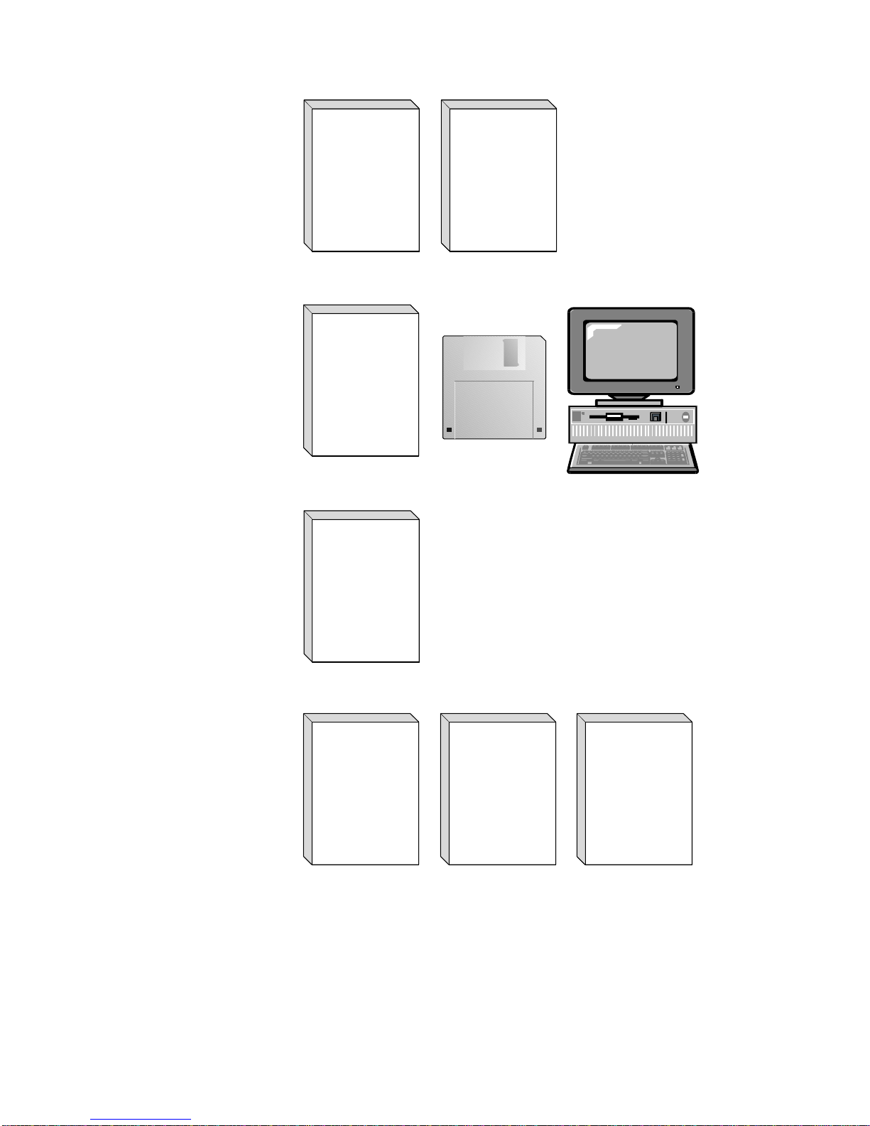
Introduction
and
Planning
Guide
GA27-4068
Configuration
Program
User's
Guide
GC30-3830
Service
and
Maintenance
Manual
Installation
and
Initial
Configuration
Guide
GC30-3867
Configuration
Help
Configuration
Program
READ.ME
SY27-0345
Software
Operations
and Network
User's
Guide
Administration
SC30-3886
Figure 1. IBM 2210 Nways Multiprotocol RouterLibrary Overview
Protocol
Configuration
and
Monitoring
Reference
SC30-3884
SC30-3885
Event
Logging
System
Messages
Guide
SC30-3682
iv 2210 Install and Initial Config
Page 7

Library Description
Introduction and Planning
GA27-4068
IBM 2210 Nways Multiprotocol Router Introduction and Planning
Guide
This book is shipped with the 2210. It explains how to prepare for
your network and for installation.
This book provides translations of danger notices and other safety
information.
GC30-3867
IBM 2210 Nways Multiprotocol Router Installation and Initial
Configuration Guide
It explains how to prepare for installation, install the 2210, perform
an initial configuration and verify that the installation is successful.
This book provides translations of danger notices and other safety
information.
Diagnostics and Maintenance
SY27-0345
IBM 2210 Nways Multiprotocol Router Service and Maintenance
Manual
This book is shipped with the 2210. It provides instructions for
diagnosing problems with and repairing the 2210.
Operations and Network Management
SC30-3681
SC30-3680
SC30-3865
SC30-3682
Software User’s Guide for Multiprotocol Routing Services
This book explains how to:
¹ Configure, monitor, and use the IBM Multiprotocol Routing
Services software shipped with the router.
¹ Use the Multiprotocol Routing Services command-line router
user interface to configure and monitor the network interfaces
and link-layer protocols shipped with the router.
Protocol Configuration and Monitoring Reference Volume 1 for
Multiprotocol Routing Services
Protocol Configuration and Monitoring Reference Volume 2 for
Multiprotocol Routing Services
These books describe how to access and use the Multiprotocol
Routing Services command-line router user interface to configure
and monitor the routing protocol software shipped with the router.
They include information about each of the protocols that the
devices support.
IBM Nways Event Logging System Messages Guide
This book contains a listing of the error codes that can occur, along
with descriptions and recommended actions to correct the errors.
About This Guide v
Page 8

Configuration
Online help The help panels for the Configuration Program assist the user in
understanding the program functions, panels, configuration
parameters, and navigation keys.
GC30-3830
Configuration Program User’s Guide for Multiprotocol Routing
Services
This book discusses how to use the Configuration Program.
GG24-4446
IBM 2210 Nways Multiprotocol Router Description and Configuration
Scenarios
This book contains examples of how to configure protocols using
IBM Multiprotocol Routing Services.
Safety
SD21-0030
Caution: Safety Information - Read This First
This book provides translations of caution and danger notices
applicable to the installation and maintenance of an IBM 2210.
Library Ordering Information
All 2210 publications can be ordered separately.
These publications are shipped in hardcopy with the 2210:
IBM 2210 Nways Multiprotocol Router Introduction and Planning Guide
IBM 2210 Nways Multiprotocol Router Installation and Initial Configuration
Guide
IBM 2210 Nways Multiprotocol Router Service and Maintenance Manual
Caution: Safety Information - Read This First
These publications are shipped with the Configuration Program in softcopy on a
CD-ROM:
IBM 2210 Nways Multiprotocol Router Introduction and Planning Guide
IBM 2210 Nways Multiprotocol Router Installation and Initial Configuration
Guide
IBM 2210 Nways Multiprotocol Router Service and Maintenance Manual
Software User’s Guide for Multiprotocol Routing Services
Protocol Configuration and Monitoring Reference Volume 1 for Multiprotocol
Routing Services
Protocol Configuration and Monitoring Reference Volume 2 for Multiprotocol
Routing Services
IBM Nways Event Logging System Messages Guide
Configuration Program User’s Guide for Multiprotocol Routing Services
IBM Multiprotocol Routing Services and IBM 2210 Softcopy Library
vi 2210 Install and Initial Config
Page 9

Obtaining Softcopy Information
Softcopy BookManager READ library information is available for many of the 2210
publications in the
single order for the CD-ROM, use form number SK2T-6012. To place a single
order for the 3480 cartridge, use form number SK2T-6013.
IBM Networking Systems Softcopy Collection Kit.
To place a
Yearly subscriptions to the
product number 5636-PUB, are available through your branch office representative.
Order feature code 2003 and media code 5003 for CD-ROM format. Order feature
code 2004 and media code 5004 for 3480 cartridge format.
IBM Networking Systems Softcopy Collection Kit
System Library Subscription Service
The 2210 publications are available via the System Library Subscription Service
(SLSS). Use machine type 2210 and program number 5765-B86 to receive 2210
publications.
Visit Our Web Site
Visit the IBM 2210 website at
¹ Engineering changes, clarifications, and fixes that have been implemented after
the manuals were printed,
¹ PTFs, configuration programs, and MRNS and MRS releases
¹ Publications
¹ Questions & Answers
http://www.networking.ibm.com/220/220prod.html
,
for:
About This Guide vii
Page 10

viii 2210 Install and Initial Config
Page 11

Summary of Changes
The following changes to the IBM 2210 library have been made:
¹ Reorganized hardware information:
– The title of the
Guide
, GA27-4086, has been changed to the
2210 Nways Multiprotocol Router Planning and Setup
Router Introduction and Planning Guide
This book now contains only information that introduces IBM 2210 router
and information necessary for planning your network. Installation
instructions have been moved into the new
Router Installation and Initial Configuration Guide
– The title of the
1Ux Installation Guide
2210 Nways Multiprotocol Router IBM 2210 Models 1Sx and
, GC30-3867, has changed to the
Multiprotocol Router Installation and Initial Configuration Guide
It now contains instructions for installing all models of the 2210. In
addition, it guides you through the initial configuration once you have
installed the 2210 router.
¹ Information to support hardware
– New adapters:
- 4-port S/T ISDN BRI adapter
- 4-port U ISDN BRI adapter
¹ Information to support software
– New Functions:
- Dial-In Access to LAN Servers (DIALs)
- Delete Interface command
- Full WAN support for concentration adapters
- Spare interface definition for dynamic reconfiguration
- Ethernet Local MAC Address Administration
2210 Nways Multiprotocol
2210 Nways Multiprotocol
.
2210 Nways
.
– Enhanced Functions:
Copyright IBM Corp. 1994, 1997 ix
- Bridging Enhancements
¹ SR-TB duplicate MAC address support – allows a duplicate MAC
address to exist in an SR domain and also offers a load-balancing
feature.
- DLSw Enhancements:
¹ Circuit priority – allows you to set the circuit priority for a range of
SAPs and MAC addresses.
¹ MAC address list – allows you to build address lists for DLSw
sessions to exchange as described in RFC 1795.
¹ NetBIOS SesionAlive spoofing – allows you to disable TCP
keepalive messages for dial-on-demand circuits.
- Serviceability Enhancements
¹ TFTP disable – to prevent unwanted updates or retrievals of device
software from the network
Page 12

¹ ICMP redirect disable – prevents the device from transmitting a
packet on the same interface on which it received the packet.
¹ Time-activated load – to allow you to load software into a device in
off-peak hours unattended.
– Protocol Enhancements:
- AppleTalk
¹ Support for AppleTalk network management applications.
- APPN
¹ Support for APPN Branch Extender which decreases the overall
size of a topology database.
¹ Improved management of topology database by removing database
records for resources that are no longer active in the network.
¹ Support for an APPN frame relay port that uses BAN.
¹ Support for an implicit focal point which will allow you to specify a
node with network management responsibilities on the device. The
device uses this focal point when it cannot establish a session with
an explicit focal point.
¹ The ability to configure the size of the held alert queue.
- ATM:
¹ RFC 1483 bridging over ATM PVCs and SVCs.
¹ Shared RFC 1483 PVCs
¹ LAN emulation quality of service.
¹ Next Hop Routing Protocol (NHRP) client.
¹ ATM virtual interface.
¹ Redundant default IP gateways for emulated LANs.
¹ Classical IP (CIP) redundancy
¹ Distributed ARP server support which provides continuous
connectivity across logical IP subnets in the event of an ARP
server failure.
¹ Support for RFC 1577+ clients.
- BRS
¹ The ability to define default circuit traffic classes for BRS.
¹ Improvements that allow assigning TCP/IP packets to a BRS class
and priority based on a TCP/UDP port number, a TCP/UDP port
range, or a TCP/UDP socket.
- Frame Relay:
x 2210 Install and Initial Config
¹ Frame Relay now runs on V.25bis.
¹ Data compression supported on Frame Relay.
Note: If you are currently using compression on PPP interfaces,
you will need to configure compression contexts for
compression to work.
¹ Improved congestion control using BECN, FECN, and CLLM.
Page 13

- IP:
¹ Support for RIP Version 2
¹ The ability to define up to 4 static routes for each IP destination
host or subnet.
¹ The ability to define the same IP subnet on multiple network
interfaces.
¹ Improved determination of whether a static route will work.
¹ Improvements to route filtering and routing policies.
¹ OSPF demand circuits for OSPF topology refreshes and hello
messages.
¹ PING enhancements
- IPX:
¹ The ability to configure IPX static routes and services to prevent
RIP and SAP from activating V.25bis and ISDN demand circuits.
¹ The ability to configure a default route to a destination network.
¹ PING enhancements
- ISDN:
¹ I.430 and I.431 support
- PPP:
¹ Increased bandwidth by increasing the number of links through
Bandwidth Allocation Protocol/Bandwidth Allocation Control
Protocol (BAP/BACP).
¹ Enhanced authentication using authentication servers.
¹ Support for Encryption Control Protocol (ECP) negotiation using
Data Encryption Standard (DES) Cypher Block Chaining (CBC)
mode.
- SNMP Enhancements:
¹ Upgrade or Addition of the Following MIBs:
– Appletalk MIB
– APPN family of MIBs
– ATM
– BRS MIB
– Ethernet
– HPR
– Interfaces MIB
– IP over ATM MIB
– IPX MIB
– ISDN MIB
– LAN Emulation Client
– NHRP MIB
– PPP MIB
Summary of Changes xi
¹ New trap support
– FR traps for the receipt of FECN, BECN, and CLLM
Page 14

- WAN Reroute Enhancements:
¹ The ability to dial up additional circuits when the primary circuit
capacity is exceeded.
¹ Allows Frame Relay traffic to use ISDN circuits as alternate circuits.
- X.25 Enhancements:
¹ New change commands for XTP.
¹ Clarifications and corrections
The technical changes and additions are indicated by a vertical line (]) to the
left of the change.
xii 2210 Install and Initial Config
Page 15

Contents
About This Guide .................................... iii
Who Should Use This Guide .............................. iii
Library Description . . . . . . . . . . . . . . . . . . . . . . . . . . . . . . . . . . v
Library Ordering Information ............................. vi
Obtaining Softcopy Information .......................... vii
System Library Subscription Service ......................... vii
Visit Our Web Site ................................... vii
Summary of Changes ................................. ix
Chapter 1. Installing the 2210 ............................ 1
Preparing for Installation ................................. 2
Verifying the Shipment Inventory ............................ 2
Placing the IBM 2210 on the Table or in the Rack ................. 4
Placement on a Table ................................ 4
Placement in a Rack ................................. 5
Connecting the Cables .................................. 8
Connecting the Power Cord .............................. 11
Attaching the IBM 2210 to Devices ......................... 11
Verifying Operation . . . . . . . . . . . . . . . . . . . . . . . . . . . . . . . . . . . 12
Chapter 2. Problem Solving . . . . . . . . . . . . . . . . . . . . . . . . . . . . 13
LED Status and Trouble Shooting Checklist .................... 13
LED Status . . . . . . . . . . . . . . . . . . . . . . . . . . . . . . . . . . . . . . 13
TroubleShooting Checklist . . . . . . . . . . . . . . . . . . . . . . . . . . . . . 14
Chapter 3. Accessing Your IBM 2210 ...................... 15
Attaching an ASCII Terminal to the Service Port .................. 15
ASCII Terminals and Setup Attributes ........................ 15
Setup Attributes . . . . . . . . . . . . . . . . . . . . . . . . . . . . . . . . . . . . . 16
IBM 3101 Setup Attributes ........................... 16
IBM 3151 Setup Attributes ........................... 16
IBM 3161 Setup Attributes ........................... 17
Chapter 4. Performing the Initial Configuration ................ 19
Setting Up the Router (Initial Configuration) .................... 19
After Initial Configuration ............................... 20
Full Configuration . . . . . . . . . . . . . . . . . . . . . . . . . . . . . . . . . . . . 20
Chapter 5. Maintenance . . . . . . . . . . . . . . . . . . . . . . . . . . . . . . . 23
Maintenance for 1Sx or 1Ux models ......................... 23
Maintenance for all other models ........................... 23
Appendix A. Installing Options . . . . . . . . . . . . . . . . . . . . . . . . . . 25
Installing Options in Models 12x ........................... 25
Installing Options in Models 14T and 24x ...................... 25
Cover . . . . . . . . . . . . . . . . . . . . . . . . . . . . . . . . . . . . . . . . . . . 25
Removing the Cover ................................ 25
Reinstalling the Cover ............................... 27
Installing Optional Adapters ............................ 28
Copyright IBM Corp. 1994, 1997 xiii
Page 16

Removing the Optional Adapter .......................... 29
Installing a Second Service Port in Models 14T and 24x ............. 30
Installing the EIA 232 Service Port Feature in Models 14T and 24x ..... 30
Removing the EIA 232 Service Port Feature in Models 14T and 24x .... 31
Installing the 14.4 Kbps Modem Port Feature in Models 14T and 24x .... 31
Removing the 14.4 Kbps Modem Port Feature in Models 14T and 24x ... 32
Handling Static-Sensitive Devices .......................... 32
Replacing the DRAM SIMM for the 12x Models ................. 32
Removing the Flash and DRAM SIMMs in Model 14T and 24x ........ 33
Installing the Flash and DRAM SIMMs in Models 14T and 24x ........ 34
Appendix B. Notices . . . . . . . . . . . . . . . . . . . . . . . . . . . . . . . . . 37
Electronic Emission Notices .............................. 37
Notices for Models 12x, 14T, and 24x ...................... 37
Notices for Models 1Sx and 1Ux ......................... 38
Notices for All Models ............................... 38
Japanese Voluntary Control Council for Interference (VCCI) Statement . 38
European Community (CE) Mark of Conformity Statement ......... 39
Notice about Lithium Battery .......................... 40
U.K. Safety Approval .............................. 40
Telecommunication Notices . . . . . . . . . . . . . . . . . . . . . . . . . . . . . . 40
FCC Part 68 Compliance Information ...................... 40
Industry Canada Information ............................ 41
Safety Notices . . . . . . . . . . . . . . . . . . . . . . . . . . . . . . . . . . . . . 43
Danger: . . . . . . . . . . . . . . . . . . . . . . . . . . . . . . . . . . . . . . 43
Gevaar: . . . . . . . . . . . . . . . . . . . . . . . . . . . . . . . . . . . . . . 43
Pericolo: . . . . . . . . . . . . . . . . . . . . . . . . . . . . . . . . . . . . . 43
Vorsicht: . . . . . . . . . . . . . . . . . . . . . . . . . . . . . . . . . . . . . 43
Perigo: . . . . . . . . . . . . . . . . . . . . . . . . . . . . . . . . . . . . . . 44
Peligro: . . . . . . . . . . . . . . . . . . . . . . . . . . . . . . . . . . . . . . 44
Fare: . . . . . . . . . . . . . . . . . . . . . . . . . . . . . . . . . . . . . . . 45
Vaara: . . . . . . . . . . . . . . . . . . . . . . . . . . . . . . . . . . . . . . . 45
Fare! . . . . . . . . . . . . . . . . . . . . . . . . . . . . . . . . . . . . . . . . 45
Varning — livsfara: ............................... 45
Perigo: . . . . . . . . . . . . . . . . . . . . . . . . . . . . . . . . . . . . . . 46
Danger: . . . . . . . . . . . . . . . . . . . . . . . . . . . . . . . . . . . . . . 46
UL Notices . . . . . . . . . . . . . . . . . . . . . . . . . . . . . . . . . . . . . . . . 49
Trademarks . . . . . . . . . . . . . . . . . . . . . . . . . . . . . . . . . . . . . . . 49
Index . . . . . . . . . . . . . . . . . . . . . . . . . . . . . . . . . . . . . . . . . . . 51
xiv 2210 Install and Initial Config
Page 17

Chapter 1. Installing the 2210
DANGER
An electrical outlet that is not correctly wired could place hazardous
voltage on metal parts of the IBM 2210 or the devices that attach to
the IBM 2210. It is the responsibility of the customer to ensure that
the outlet is correctly wired and grounded to prevent an electrical
shock.
Before installing or removing signal cables, ensure that the power
cord for the IBM 2210 is unplugged.
When possible, use one hand to connect or disconnect signal cables
to prevent a possible shock from touching two surfaces with different
electrical potentials.
During an electrical storm, do not connect or disconnect any cables.
Note: For translations of this safety notice, see “Safety Notices” on page 43.
To install the IBM 2210, you will first install the hardware, and then perform an
initial configuration if your router was not configured at the factory.
1. To install the hardware, see the following sections of this guide:
a. “Preparing for Installation” on page 2
b. “Installing Options in Models 14T and 24x” on page 25, if needed
c. “Placing the IBM 2210 on the Table or in the Rack” on page 4
d. “Connecting the Cables” on page 8
e. “Connecting the Power Cord” on page 11
f. “Attaching the IBM 2210 to Devices” on page 11
g. “Verifying Operation” on page 12
2. If the IBM 2210 was not pre-configured at the factory, see Chapter 4,
“Performing the Initial Configuration” on page 19 to perform an initial
configuration.
If your IBM 2210 is configured with just an IP address and a Bootp server
address, the IBM 2210 will use the EasyStart feature to obtain a full
configuration from the Bootp Server. EasyStart is described in
Software User’s
Guide for Multiprotocol Routing Services
If the IBM 2210 has an IP address and is connected to a network, you can also
use the Configuration Program to send a full configuration to the router and
restart the router.
To configure protocols, transports, and features you need on the IBM 2210, using
the built-in configuration program, refer to the following publications:
Software User’s Guide for Multiprotocol Routing Services
¹
¹
Protocol Configuration and Monitoring Reference
To use the Configuration Program, refer to
Multiprotocol Routing Services
Copyright IBM Corp. 1994, 1997 1
Configuration Program User’s Guide for
.
Page 18

An additional source of information is the
Description and Configuration Scenarios
Preparing for Installation
Note: Before installing the IBM 2210, be sure to read “Electronic Emission
Notices” on page 37.
Before beginning the installation procedure, make sure that the following tasks have
been completed:
¹ If the IBM 2210 is to be placed in a rack, provide a rack that meets the
requirements and that has space for the IBM 2210. See “Placing the IBM 2210
on the Table or in the Rack” on page 4 for information about rack
requirements. You will also need to provide the mounting hardware appropriate
for your rack.
¹ Verify that appropriate power outlets are available.
¹ Unpack the IBM 2210 and place it where it is to be installed.
¹ Provide any network interface cables not ordered with the IBM 2210.
¹ If the IBM 2210 was not pre-configured at the factory, you will need an ASCII
terminal to perform initial configuration. See “Attaching an ASCII Terminal to
the Service Port” on page 15 for information about ASCII terminals.
IBM 2210 Nways Multiprotocol Router
, GG24-4446.
Verifying the Shipment Inventory
Check the components included with your shipment using the following list.
Hardware
¹ IBM 2210
¹ Network interface cables (optional)
¹ Service port cable
¹ Adhesive-backed feet (not available with all models)
¹ Cable management bracket (not available with all models)
¹ AC power cord
¹ Service kit with wrap plugs and service port converter (optional)
Optional Features
The following models of the 2210 support the following features:
2 2210 Install and Initial Config
Page 19

|
Table 1. IBM 2210 Models
| Supports
| No. of WANs
| Base Flash
| Base
| Adapter
| Model| LAN
| (see note)| ISDN BRI
| Memory
| DRAM
| Features
| 1S4*| Ethernet| 1| 1| 2 MB| 4 MB| No
| 1S8*| Ethernet| 1| 1| 4 MB| 8 MB| No
| 1U4*| Ethernet| 1| 1| 2 MB| 4 MB| No
| 1U8*| Ethernet| 1| 1| 4 MB| 8 MB| No
| 12T| Token-ring| 2| 0| 4 MB| 8 MB| No
| 12E| Ethernet| 2| 0| 4 MB| 8 MB| No
| 127| Token-ring| 2| 1| 4 MB| 8 MB| No
| 128| Ethernet| 2| 1| 4 MB| 8 MB| No
| 14T| Token-ring| 4| 0, 1, or 4
| 4 MB| 16 MB| Yes
| (optional)
| 24T| 2 Token-ring| 4| 0, 1, or 4
| 4 MB| 16 MB| Yes
| (optional)
| 24E| 2 Ethernet| 4| 0, 1, or 4
| 4 MB| 16 MB| Yes
| (optional)
| 24M| 1 Token-ring
| 4| 0, 1, or 4
| 4 MB| 16 MB| Yes
| 1 Ethernet
| (optional)
| Note:
| The standard WAN ports on the IBM 2210 will support any of these physical interfaces:
| ¹ EIA 232-D/V.24
| ¹ V.35
| ¹ V.36
| ¹ X.21
| WAN Net Handlers:
| ¹ V.25 bis (not supported on X.21)
| ¹ X.25
| ¹ PPP
| ¹ FR
| ¹ SDLC
| ¹ SDLC Relay
| ¹ V.34 (only supported on EIA-232)
| Expandable base DRAM:
| ¹ Base DRAM for the 12x can expand to 16 MB.
| ¹ Base DRAM for the 14x can expand to 32 MB.
| *The 1S4, 1S8, 1U4, and 1U8 can use either the ISDN BRI or WAN port at any given time.
These items will be installed in your IBM 2210 if ordered with the unit:
¹ 16 MB Memory Expansion Feature
¹ 32 MB DRAM Expansion Feature
| ¹ 1-Port ISDN Basid Rate Interface Adapter
| ¹ 4-Port ISDN BRI Adapter
| ¹ 14.4 Kbps Modem Port Feature
| ¹ EIA 232 Service Port Feature
| ¹ E1 120-ohm ISDN PRI Adapter
| ¹ T1/J1 ISDN PRI Adapter
| ¹ 4-Port WAN Concentration Adapter
| ¹ 8-Port WAN Concentration Adapter
| ¹ 25-Mbps ATM Interface Adapter
Chapter 1. Installing the 2210 3
Page 20
The following documentation is provided:
¹
IBM 2210 Nways Multiprotocol Router Introduction and Planning Guide
¹
IBM 2210 Installation and Initial Configuration Guide
¹
IBM 2210 Nways Multiprotocol Router Service and Maintenance Guide
Store the books near the machine.
Placing the IBM 2210 on the Table or in the Rack
Models 1S4, 1S8, 1U4, and 1U8 are for table top use. The other models can be
placed on a tabletop or rack. The following figures use a 12x model as an
example.
Placement on a Table
If you are placing the IBM 2210on a table:
1 Attach the four adhesive-backed feet to the bottom of the IBM 2210 at the
corners.
(this book)
Figure 2. Attaching the Feet to the Bottom of the IBM 2210
2 Place the IBM 2210 on the table and go to “Connecting the Cables” on
page 8.
4 2210 Install and Initial Config
Page 21

Placement in a Rack
If you choose rack-mounting, you must provide the rack; it is not provided with the
2210.
You can use any EIA standard 19-inch rack. The rack can be open or closed.
However, if you choose a closed rack, you must make sure that enough air flows
through the 2210. Covers on the front of the rack that would not let air reach the
2210 must be removed or modified to let air pass. Similarly, unvented rear rack
covers that would not let air exit the 2210 or would cause back pressure to build up
from several machines must not be used.
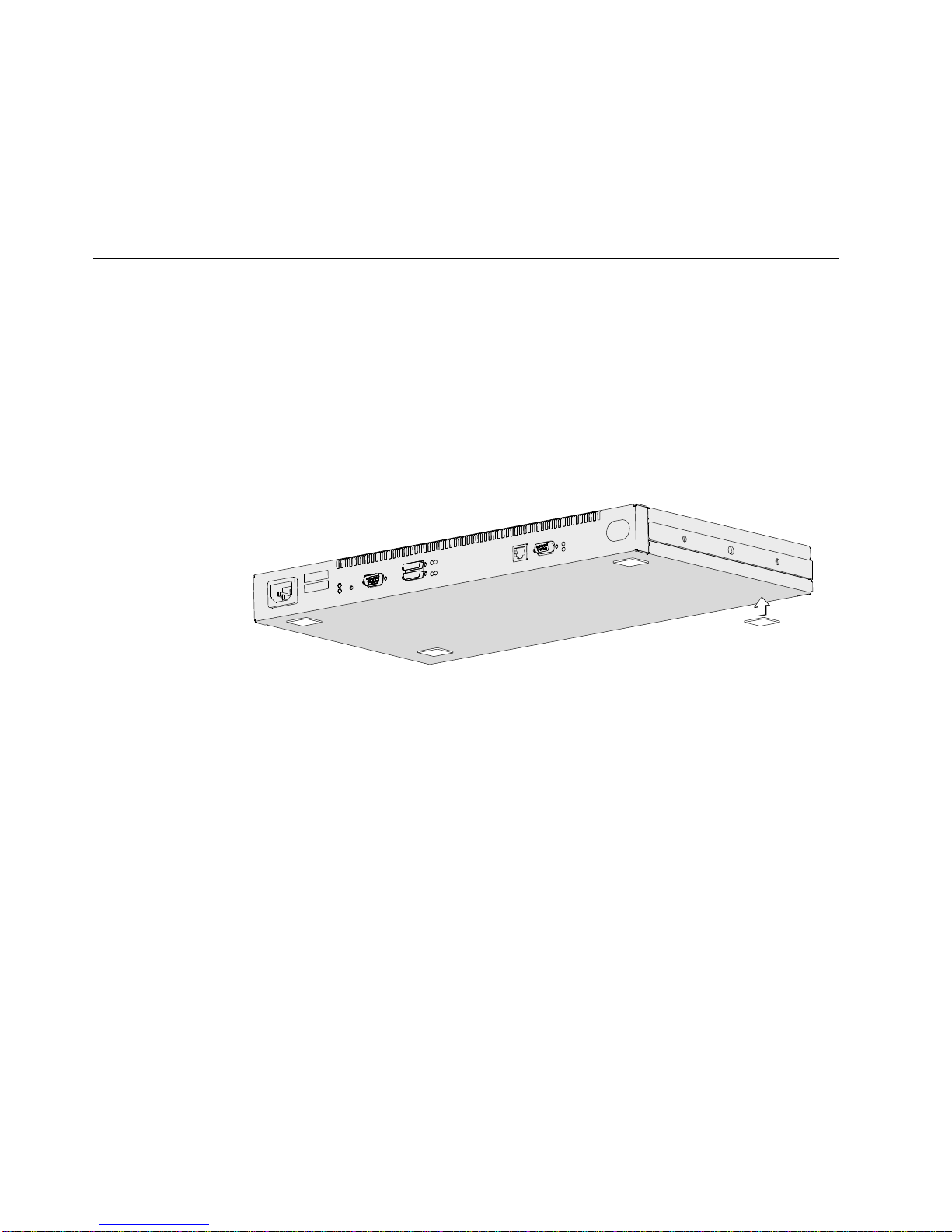
If you are placing the IBM 2210 in a rack:
1 To install the IBM 2210 with the cables at the back of the rack, go to step 2
on page 6.
To install the IBM 2210 with the cables at the front of the rack, follow these
steps for each rack-mounting bracket:
a Remove the outer screws that attach the mounting bracket to the side
of the IBM 2210.
Figure 3. Removing the Screws on the Mounting Bracket
Chapter 1. Installing the 2210 5
b Turn the bracket around so that the ear is in front and is pointed away
from the machine.
Page 22
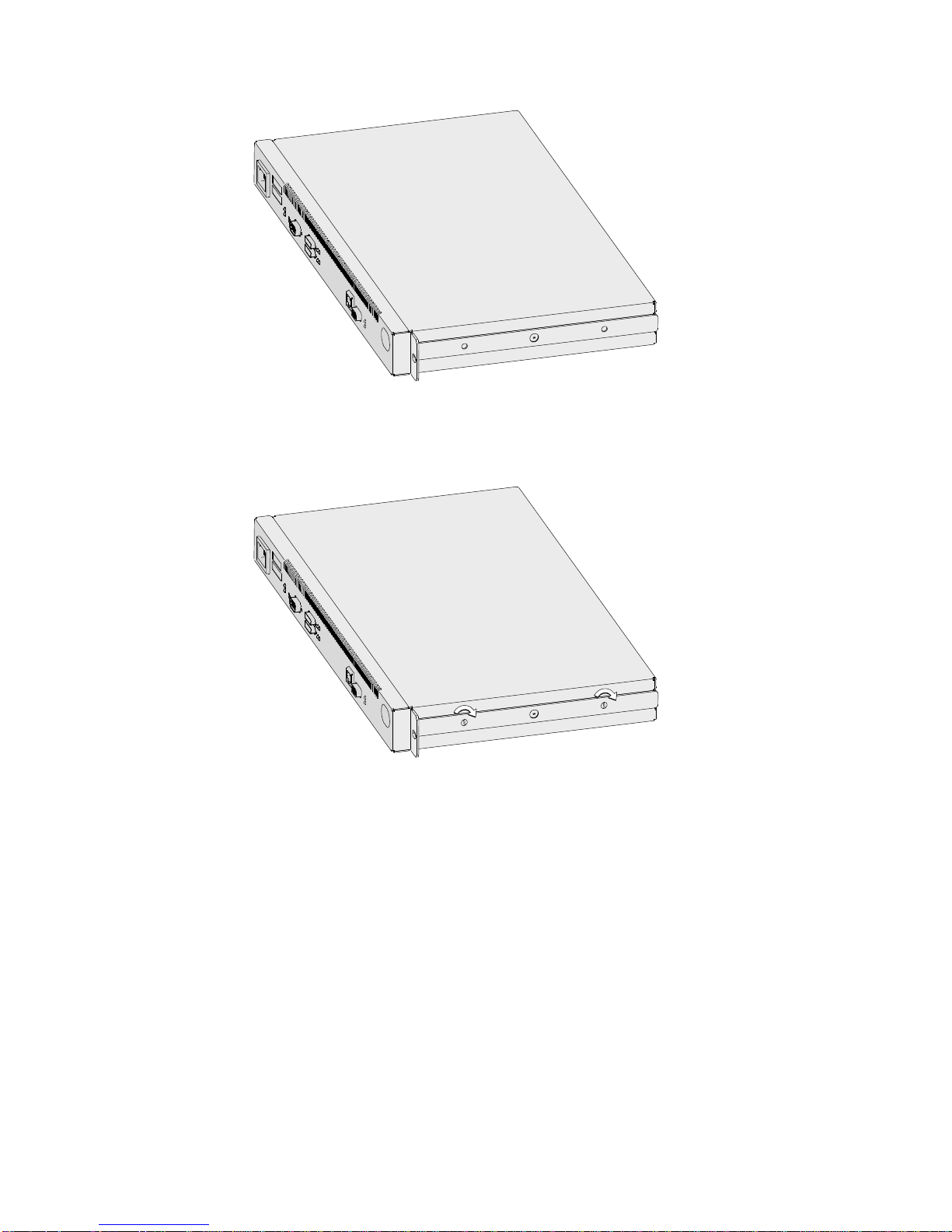
Figure 4. Turning the Mounting Bracket
c Secure the bracket to the IBM 2210.
Figure 5. Securing the Mounting Bracket
d Go to step 3 on page 7.
2 To install the IBM 2210 with the cables at the back of the rack, follow these
steps for each rack-mounting bracket:
a Remove the outer screws that attach the mounting bracket to the side
6 2210 Install and Initial Config
of the IBM 2210.
Page 23

Figure 6. Removing the Screws on the Mounting Bracket
b Turn the mounting bracket so that the ear faces away from the
machine.
Figure 7. Turning the Mounting Bracket
3 Select the desired position for the IBM 2210 in the rack.
4 Attach the IBM 2210 to the rack using mounting hardware appropriate for
your rack.
Chapter 1. Installing the 2210 7
c Secure the bracket to the IBM 2210.
Page 24

5 A cable management bracket is provided. If you wish to use it, install it as
shown here.
Figure 8. Attaching the Cable Management Bracket
Connecting the Cables
The ports of the different models of the IBM 2210 are shown below. Find the
picture of the model you are installing. Connect the cables to the ports.
Notes:
1. If your IBM 2210 was not pre-configured at the factory, you must attach an
ASCII terminal to the service port to perform initial configuration of the IBM
2210. For information about attaching an ASCII terminal, go to “Attaching an
ASCII Terminal to the Service Port” on page 15.
2. Be sure to follow standard CCITT I.430 when connecting cables to the ISDN
port on the models that support ISDN, including the correct wall termination for
your ISDN network.
Figure 9. Model 12T
Service
Port
Token-Ring
WANs UTP STP
8 2210 Install and Initial Config
Page 25

Ethernet
Figure 10. Model 12E
Figure 11. Model 127
Service
Port
Service
Port
Service
Port
WANs 10 BASE-T
AUI
Token-Ring
WANs UTP STP ISDN
Ethernet
WANs 10 BASE-T
AUI ISDN
Figure 12. Model 128
Primary Service Port
Figure 13. Model 14T
Second
Service Port
Token-Ring
WANs WANs
UTP STP
Adapter Slot
Chapter 1. Installing the 2210 9
Page 26

Primary Service Port
Figure 14. Model 24T
Second
Service Port
Second
Service Port
Token-Ring
WANs WANs
UTP STP
Ethernet
10 BASE-T AUI
WANs WANs
Token-Ring
UTP STP
Adapter Slot
Ethernet
10 BASE-T AUI
Primary Service Port
Figure 15. Model 24E
Primary Service Port
Figure 16. Model 24M
Second
Service Port
Service
Ethernet
10 BASE-T AUI
WANs WANs
WAN Ethernet
ISDN-BRI
Adapter Slot
Token-Ring
UTP STP
Adapter Slot
Figure 17. Models 1Sx and 1Ux
10 2210 Install and Initial Config
100-240VAC10
0.25-0.15A 50/60Hz
Page 27

Connecting the Power Cord
Connect the power cord to the IBM 2210. Do not connect the power cord to the
power outlet.
Figure 18. Connecting the Power Cord to the IBM 2210
Attaching the IBM 2210 to Devices
To connect each network interface cable to a device:
1 Identify the correct device.
2 Connect the network interface cable to the device.
Note: Always power off any peripheral device before connecting it to or
disconnecting it from a network interface cable. If you connect or disconnect this
cable while the peripheral device is powered on, the IBM 2210 may perform an
initial program load (IPL).
Chapter 1. Installing the 2210 11
Page 28

Verifying Operation
As soon as you plug in the IBM 2210, the power-on self-test (POST) begins.
During the POST, the LEDs light in various combinations. The POST and boot will
require about 1 minute. At the end of the boot, the green LEDs for the system
(OK) and for any port that is active should be on or blinking. Figure 19 shows the
LED states for a IBM 2210 Model 12T after a successful boot.
Green LEDs on / blinking
OK
Figure 19. LEDs On or Blinking on Port Side after Successful Boot
2
1
WAN UTP STP Token RingService
Note: The port LEDs will not light for any port that is not being used.
An example of the LED states after a successful boot on the side of the machine
opposite the ports is shown in Figure 20.
Green LEDs on / blinking
OK WAN 1 WAN 2 Token Ring
Figure 20. LEDs On or Blinking on Non-Port Side after Successful Boot
If the LEDs indicate a successful power-on and the IBM 2210 was pre-configured at
the factory, your installation is complete. At this point, you should contact your
network administrator and request that person to back up your base code.
Instructions for this task are in the
User’s Guide
.
IBM Multiprotocol Routing Services Software
If the IBM 2210 was not pre-configured at the factory and the boot was successful,
both system (OK) LEDs blink and all port LEDs are off. Continue with Chapter 4,
“Performing the Initial Configuration” on page 19.
If the LEDs do not indicate a successful power-on, continue with the Chapter 2,
“Problem Solving” on page 13.
When power to the 2210 adapter slot fails, look at the adapter status LED located
at the lower side of the adapter bracket near the right thumbscrew. If the adapter
status LED is off, there is a slot power failure. Continue with the Chapter 2,
“Problem Solving” on page 13.
12 2210 Install and Initial Config
Page 29

Chapter 2. Problem Solving
LED Status and Trouble Shooting Checklist
LED Status
Table 2. System LED States
Green Amber Action
On Off Router loaded and operational.
On or Off On Replace the system board. If this is a 1Sx or 1Ux
model, replace the unit.
Off Blinking Replace the DRAM SIMM. If this is a 1Sx or 1Ux
model, replace the unit.
On Blinking Either:
¹ There is no router load module available, no
boot configuration has been entered, or the
configured boot path is not available.
Additional information can be obtained by
attaching a service terminal to the IBM 2210. If
the problem cannot be resolved locally, call the
network administrator.
¹ The router is in the process of loading from the
network. If this is the case, the green port LED
on the port that is being used for the load will
also be blinking.
Blinking On Replace the flash SIMM on models 14T and 24x.
For 12x models, refer to the “Nways Multiprotocol
Router Service and Maintenance Guide”
publication. If this is a 1Sx or 1Ux model, replace
the unit.
Blinking Blinking Load from the IBD is in process.
Copyright IBM Corp. 1994, 1997 13
Page 30

TroubleShooting Checklist
Table 3. Troubleshooting Checklist
Symptom Action
No LEDs are on ¹ Make sure the power cord is plugged into an
The system LED (OK) is green,
but a port LED is amber
Adapter status LED is OFF ¹ Is the adapter enablement feature installed?
outlet
¹ Verify that your power outlet is good
If you are not using the port with the amber LED
on, you may continue.
If you are using the port:
¹ Make sure the cable for that port is securely
connected
¹ Contact the network administrator to make sure
the network is set up correctly
¹ Check for correct power cables?
¹ Check the adapter slot power supply.
¹ Check the adapter.
¹ Contact IBM service.
If you locate the problem, execute the POST again by unplugging the power cord
from the wall outlet and then plugging it in again. If the LEDs indicate a successful
power-on and the IBM 2210 was pre-configured at the factory, your installation is
complete; if the IBM 2210 was not pre-configured, continue with Chapter 4,
“Performing the Initial Configuration” on page 19.
If you cannot determine the problem, call your service representative.
14 2210 Install and Initial Config
Page 31

Chapter 3. Accessing Your IBM 2210
If your router was not pre-configured, or if you did not use the EasyStart function,
you will need to configure the router manually. To do this, you must first attach an
ASCII terminal to the IBM 2210.
Attaching an ASCII Terminal to the Service Port
Attach an ASCII terminal or emulator (with the appropriate emulation software) to
the service port to provide local or remote access to the IBM 2210 as shown in
Figure 21.
100-240VAC10
0.4-0.2A50/60Hz
Figure 21. Attaching an ASCII Terminal to the Service Port
the service port has a factory default setting of 9600 bps.
Note: The IBM 2210 service port can be damaged by static electricity discharge.
It is shipped with a plastic port cover to prevent such damage. Remove the plastic
cover when you are attaching a terminal and store it in a safe place. When you
disconnect the terminal, reinstall the plastic cover.
ASCII Terminals and Setup Attributes
The DEC VT100 ASCII terminal is supported, as well as devices, such as personal
computer systems, that are configured to emulate it. Configure a VT100 with:
¹ No parity
¹ 8-bit word length
¹ 1 stop bit
¹ 300 bps–38.4 Kbps bit rate
Copyright IBM Corp. 1994, 1997 15
Page 32

Setup Attributes
The following terminals are also supported:
¹ IBM 3101 Display Terminal
¹ IBM 3151 ASCII Display Station
¹ IBM 3161 ASCII Display Station
Configure these terminals as shown in “Setup Attributes.”
IBM 3101 Setup Attributes
Use Figure 22 to determine the settings for the setup attributes for the IBM 3101
ASCII terminal.
Figure 22. Setup Attributes for the IBM 3101 Display Terminal
The 2210 can use this terminal at all bit rates (in bps) up to 19200.
IBM 3151 Setup Attributes
Activate setup mode in the IBM 3151 terminal by pressing the Ctrl and Setup keys.
The Ctrl key is located on the lower left of the keyboard. The Setup key is located
on the upper right of the keyboard.
Use Table 4 to help you determine the settings for the setup attributes.
Save the setup information by highlighting the Save function using the cursor keys.
Exit by pressing the Ctrl and Setup keys.
Table 4. Setup Attributes for the IBM 3151
Attribute Setting
Machine Mode 3151
Scroll JUMP
Auto LF OFF
Line Wrap OFF
Operating Mode ECHO
Word Length (bits) 8
Stop Bit 1
Turnaround Character CR
Line Control IPRTS
Break Signal (ms) 500
Send Null Suppress ON
16 2210 Install and Initial Config
Page 33

Supported bit rates (in bps) are:
¹ 1200
¹ 2400
¹ 4800
¹ 9600
¹ 19200
¹ 38400
IBM 3161 Setup Attributes
Activate setup mode in the IBM 3161 terminal by pressing the Ctrl and Setup keys.
The Ctrl key is located on the lower left of the keyboard. The Setup key is located
on the upper right of the keyboard. The terminal displays a setup attribute panel.
Change the attributes by moving the cursor to the various fields and typing over the
information in the field. Use Table 5 to help you determine the settings for the
setup attributes.
Press Send to save the attributes on this panel.
Table 5. Setup Attributes for the IBM 3161
Attribute Setting
Machine Mode 3161
Operating Mode ECHO
Interface RS-232C
Line Control IPRTS
Turnaround Character CR
Stop Bit 1
Word Length (bits) 8
Response Delay (ms) 100
Break Signal (ms) 500
Supported bit rates (in bps) are:
¹ 1200
¹ 2400
¹ 4800
¹ 9600
¹ 19200
You now need to set up additional attributes for the 3161. To set up the additional
attributes:
1. Press Select to display the attribute selection bar.
2. Change the values on the selection bar to match the values in Table 6 on
page 18.
To move between selections while on a selection bar, press Tab. To change a
value for an attribute, press the spacebar.
3. Press Send to accept the current values for the attributes on the selection bar.
4. Continue with step 2 until you have set all the attributes in Table 6 on
page 18.
5. Press Select after the last selection bar to exit the 3161 setup function.
Chapter 3. Accessing Your IBM 2210 17
Page 34

Table 6. Additional Setup Attributes for the IBM 3161
Attribute Setting
Enter Send
Return Field
New Line CR
Tab Field
Line Wrap On
Auto LF Page
Send Null On
Insert Space
Trace All
CRT Saver No
Scroll On
Print Viewport
Print Null On
Print EOL On
Line End CR-LF
18 2210 Install and Initial Config
Page 35

Chapter 4. Performing the Initial Configuration
If you have a new router with no configuration, or if you have cleared the router’s
configuration or encountered a problem that cleared the configuration, you must
perform the steps in this section before you can send an existing configuration to
the router.
Setting Up the Router (Initial Configuration)
To perform initial configuration on the router, you must first establish access to the
router. You can establish access either locally or remotely as described in
Chapter 3, “Accessing Your IBM 2210” on page 15. Then:
1 Perform an initial configuration to establish the IP address and IP mask for
the primary interface for the router as follows:
a
Configure Interfaces
1) Enter Yes to the Configure Interfaces question
2) Supply the interface information required for the interface which will
communicate with the Configuration Program
3) Enter Yes to the Save this configuration question
b
Configure Bridging
1) Enter No to the Configure Bridging question
c
Configure Protocols
1) Enter Yes to the Configure Protocols question
d
Configuring IP
1) Enter Yes to the Configure IP question
2) Enter Yes to the Configure IP on this interface question for the LAN
interface that will communicate with the Configuration Program
3) Enter the IP address at the IP Address prompt
4) Enter the IP mask at the Address Mask prompt
5) Enter No to the Enable Dynamic Routing question
6) Enter Yes to the Define Community question
7) Enter the community name of your choice at the Community Name
prompt
Copyright IBM Corp. 1994, 1997 19
8) Enter Yes to the Save this configuration question
9) Enter No to the Configure IP on this interface question for the other
router interfaces
e
Configuring IPX, DECnet, Booting, and Console Modem-Control
1) Enter No to the Configure IPX question, if asked
2) Enter No to the Configure DNA question, if asked
Page 36

3) Enter No to the Configure Booting question
4) Enter No to the Configure Console Modem-Control question
f
Restarting the Router
1) Enter Yes to the Restart the router question
2 Press Ctrl-p to exit Config
3 Enter restart to restart the router
When the router completes the restart sequence, it can communicate with the
Configuration Program.
After Initial Configuration
Important: After the router is configured and operational,
Full Configuration
The initial configuration procedure you have just performed will enable you to
access the router over the network if you configured an IP address for it.
The configuration provided by QCONFIG depends upon many default values for
parameters, some of which may not be appropriate to your installation. You may
need to modify the configuration that you have created using QCONFIG to
customize the router to work on your network. You can do this using either of
these methods:
¹ Configuration Program
always
active configuration file. Keeping this file enables you to re-establish the
router on the network if the active configuration becomes corrupted.
You can back up the active configuration file by retrieving it and storing it in
the workstation.
The Configuration Program is the
these reasons:
recommended
configuration method for
back up the
1 It can enable you to keep a number of copies of configuration files on a
server for uploading to the appropriate routers.
2 It does not alter any configuration parameters dynamically. This feature
helps you control changes to the router configurations.
3 It performs more input validation and cross-checking of the configuration
parameters than the other methods.
¹ Command line interface (OPCON)
The command line interface causes certain parameters to be altered
dynamically. The binary files that are created are saved on the hard disk of the
router, not in the workstation. This characteristic makes it more difficult to
manage the configuration of the router. However, the command line interface
can be used to monitor the operations of the router, whereas the Configuration
Program cannot.
20 2210 Install and Initial Config
Page 37

The command line interface is also useful when you want to change one of the
parameters that can be dynamically altered. For more information about the
command line interface, refer to the
Software User’s Guide
.
Use the
Configuration Program User’s Guide
configuration that is suitable for your network.
in order to create a complete
Chapter 4. Performing the Initial Configuration 21
Page 38

22 2210 Install and Initial Config
Page 39

Chapter 5. Maintenance
Maintenance for 1Sx or 1Ux models
If you have problems with your IBM 2210 Model 1Sx and 1Ux that require
maintenance, call your network administrator or service representative. Models 1Sx
and 1Ux have no field-replaceable parts.
Maintenance for all other models
If you have problems with models 12T, 12E, 127, 128, 14T, 24T, 24E, or 24M, refer
to the
IBM 2210 Service and Maintence Guide
.
Copyright IBM Corp. 1994, 1997 23
Page 40

24 2210 Install and Initial Config
Page 41

Appendix A. Installing Options
Installing Options in Models 12x
You can install the following options in the 12x models of the IBM 2210:
Table 7. Procedures for IBM 2210 Options
Option Installation and Removal Procedures
Memory Expansion Feature “Replacing the DRAM SIMM for the 12x Models” on
Installing Options in Models 14T and 24x
You can install the following options in the 14T and 24x models of the IBM 2210:
Table 8. Procedures for IBM 2210 Options
Option Installation and Removal Procedures
Memory Expansion Feature “Removing the Flash and DRAM SIMMs in Model 14T and
Adapters
| ¹ 1-port ISDN BRI
| ¹ 4-port ISDN BRI
¹ T1/J1 ISDN PRI Adapter
¹ E1 120-ohm ISDN PRI Adapter
¹ 4-Port WAN Concentration Adapter
¹ 8-Port WAN Concentration Adapter
¹ 25-Mbps ATM Interface Adapter
EIA 232 Service Port Feature “Cover” and “Installing the EIA 232 Service Port Feature in
14.4 Kbps Modem Port Feature “Cover” and “Installing the 14.4 Kbps Modem Port Feature
page 32
24x” on page 33
“Installing Optional Adapters” on page 28
Models 14T and 24x” on page 30
in Models 14T and 24x” on page 31
Cover
Removing the Cover
DANGER
Note: For translations of this safety notice, see “Safety Notices” on
page 43.
1 Unplug the power cord from the outlet.
Copyright IBM Corp. 1994, 1997 25
Hazardous voltages exist inside this machine when it is powered
on. Anytime you service this unit with the cover off, be sure to
unplug the power cord.
Page 42

2 If the IBM 2210 is installed in a rack, remove the screws attaching the IBM
2210 to the rack.
3 Remove the two screws that attach the mounting brackets to either side of
the IBM 2210. Then remove the center screw that attaches the cover to the
side of the IBM 2210. Note the position of the mounting bracket ears as you
remove the mounting brackets.
Figure 23. Removing the Side Screws
4 Position the IBM 2210 so that the port side is facing you. From this position,
lift the rear portion of the cover and slide it away from you.
Figure 24. Removing the Cover
5 Be sure to store the mounting brackets and screws with the cover.
26 2210 Install and Initial Config
Page 43

Reinstalling the Cover
1 Position the IBM 2210 so that the port side is facing you. From this position,
elevate the rear portion of the cover and slide it onto the IBM 2210.
Figure 25. Replacing the Cover
2 Replace the screws that attach the cover and mounting brackets to each side
of the machine. Be sure that the screw with the Phillips head is installed in
the middle hole.
Figure 26. Replacing the Screws and Mounting Bracket
3 If the IBM 2210 was mounted in a rack, return it to the rack.
4 Plug the power cord into the outlet.
Appendix A. Installing Options 27
Page 44

Installing Optional Adapters
Refer to “Handling Static-Sensitive Devices” on page 32 before removing or
installing any of the optional adapters.
Figure 27. Installing the Optional Adapter (Actual adapter may appear different)
1 Unplug the power cord.
2 Remove the blank faceplate by loosening the two screws and pulling the
plate toward you.
3 Check to ensure that the Adapter Enablement Feature is installed. Look
inside the module slot and ensure that the guide rails for the card are
present.
If the guide rails are not visible, an authorized service representative must
install the Adapter Enablement Feature. If you have not ordered the Adapter
Enablement Feature, you should do so before proceeding.
If the feature is not installed, refer to the
Router Service and Maintenance Manual
IBM 2210 Nways Multiprotocol
.
4 Remove the adapter from the antistatic bag.
5 While holding the adapter carefully by the front plate insert it into the opening.
Make sure that the edges of the adapter line up with the guide rails.
6 Press the adapter into the slot.
7 Secure the adapter in place by tightening the screws.
28 2210 Install and Initial Config
Page 45

8 Plug the power cord into the outlet.
9 Verify that the IBM 2210 is functioning correctly by using “Verifying
Operation” on page 12.
Removing the Optional Adapter
Figure 28. Removing the Adapter (Actual adapter may appear different)
1 Unplug the power cord.
2 Remove the screws holding the adapter in place.
3 Remove the adapter by gently pulling it toward you.
4 Replace the blank faceplate or install new adapter and tighten the two
screws.
5 Plug the power cord into the outlet.
6 Verify that the IBM 2210 is functioning correctly by using “Verifying
Operation” on page 12.
Appendix A. Installing Options 29
Page 46
Installing a Second Service Port in Models 14T and 24x
Refer to “Handling Static-Sensitive Devices” on page 32 before removing or
installing a second service port card.
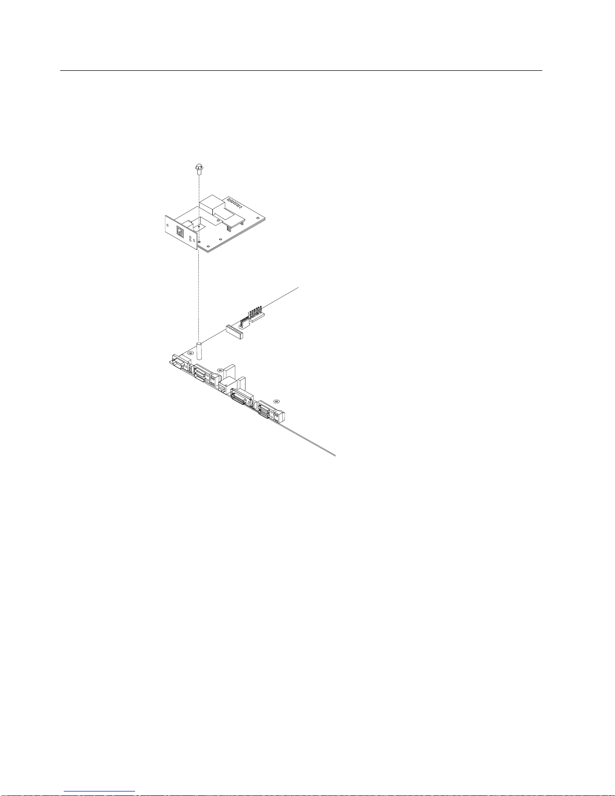
Installing the EIA 232 Service Port Feature in Models 14T and 24x
Figure 29. Installing the EIA 232 Service Port Feature
1 Remove the cover from the IBM 2210 as described in “Cover” on page 25.
2 Remove the blank Service Port faceplate by unscrewing the two screws.
3 Save the faceplate and screws.
4 Insert the EIA 232 Service Port Feature connection into the connector on the
system board.
5 Using the two screws from the blank faceplate secure the front of the Service
Port Card faceplate to the frame of the IBM 2210.
6 Fasten the middle of the EIA 232 Service Port Feature to the standoff on the
system board using the supplied Philips-head screw.
7 Replace the cover as described in “Reinstalling the Cover” on page 27.
8 Verify that the IBM 2210 is functioning correctly by using “Verifying
Operation” on page 12.
30 2210 Install and Initial Config
Page 47

Removing the EIA 232 Service Port Feature in Models 14T and 24x
1 Remove the cover from the IBM 2210 as described in “Cover” on page 25.
2 Remove the two screws that secure the EIA 232 Service Port Feature to the
IBM 2210 frame.
3 Remove the Philips-head screw that attaches the middle of the EIA 232
Service Port Feature to the standoff on the system board.
4 Remove the EIA 232 Service Port Feature connection from the system board.
5 Lift the EIA 232 Service Port Feature out of the IBM 2210 chassis.
Installing the 14.4 Kbps Modem Port Feature in Models 14T and 24x
Figure 30. Installing the 14.4 Kbps Modem Port Feature
1 Remove the cover from the IBM 2210 as described in “Cover” on page 25.
2 Remove the blank Service Port faceplate by unscrewing the two screws.
3 Save the faceplate and screws.
4 Insert the 14.4 Kbps Modem Port Feature connection into the connector on
the system board.
5 Attach the 14.4 Kbps Modem Port Feature to the system board by inserting
the alignment post through the top of the modem and screwing in the post.
Appendix A. Installing Options 31
Page 48

6 Using the two screws from the blank faceplate secure the front of the Modem
Card faceplate to the frame of the 2210.
7 Replace the cover as described in “Reinstalling the Cover” on page 27.
8 Verify the IBM 2210 is functioning correctly by using “Verifying Operation” on
page 12.
Removing the 14.4 Kbps Modem Port Feature in Models 14T and 24x
1 Remove the cover from the IBM 2210 as described in “Cover” on page 25.
2 Remove the two screws that secure the 14.4 Kbps Modem Port Feature to
the IBM 2210 frame.
3 Unscrew the alignment post and remove it from the modem.
4 Remove the 14.4 Kbps Modem Port Feature connection from the system
board.
5 Lift the 14.4 Kbps Modem Port Feature out of the IBM 2210 chassis.
Handling Static-Sensitive Devices
Certain components, such as planars and memory modules, can be damaged by
static electricity discharge. These components are shipped in an antistatic bag to
prevent such damage. An electrostatic discharge (ESD) protection device must be
used when handling these components.
Take the following precautions:
¹ Do not remove the component from the antistatic bag until you are ready to
replace a component in the IBM 2210.
¹ With the component still in its antistatic bag, touch the metal frame of the IBM
2210.
¹ Hold the component by its edges. Avoid touching solder joints or pins.
¹ Handle the components carefully in order to prevent permanent damage.
Replacing the DRAM SIMM for the 12x Models
32 2210 Install and Initial Config
Page 49
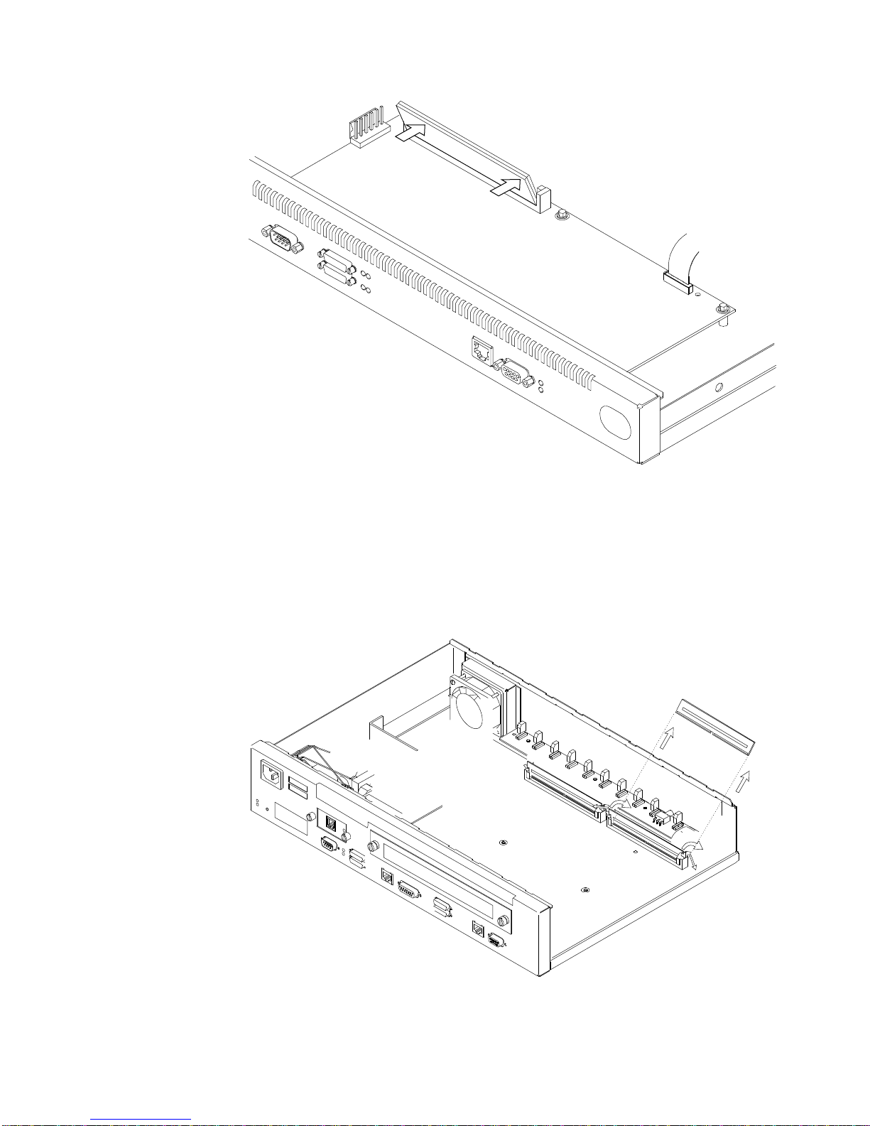
Figure 31. Replacing the DRAM SIMM in 12x Models
1 Tilt the top of the SIMM toward you and slide it into the retainer.
2 Press the SIMM backward until the retaining tabs are holding it securely.
Removing the Flash and DRAM SIMMs in Model 14T and 24x
Figure 32. Removing the Flash SIMM (14T and 24x Models)
Appendix A. Installing Options 33
Page 50

1 Remove the cover from the IBM 2210 as described in “Removing the Cover”
on page 25.
2 As you face the machine the DRAM SIMM is located in the left slot. To
replace the DRAM SIMM you must remove the existing DRAM SIMM and
install the replacement. The Flash SIMM location is shown in
Figure 32 on page 33
3 Push back the retaining tabs located at each end of the SIMM socket. The
SIMM will fall backwards.
4 Remove the SIMM by gently pulling it away from you.
5 Replace the cover on the IBM 2210 as described in “Reinstalling the Cover”
on page 27.
6 Verify that the IBM 2210 is functioning correctly by using “Verifying
Operation” on page 12.
Installing the Flash and DRAM SIMMs in Models 14T and 24x
Refer to “Handling Static-Sensitive Devices” on page 32 before removing or
installing a flash SIMM.
Figure 33. Installing the Flash SIMM (14T and 24x Models)
1 Remove the cover from the IBM 2210 as described in “Removing the Cover”
on page 25.
2 Tilt the top of the SIMM away from you and slide it into the retainer.
3 Press the SIMM forward until the retaining tabs are holding it securely.
34 2210 Install and Initial Config
Page 51

4 Replace the cover on the IBM 2210 as described in “Reinstalling the Cover”
on page 27.
5 Verify that the IBM 2210 is functioning correctly by using “Verifying
Operation” on page 12.
If the router was not pre-configured at the factory, it will enter EasyStart
automatically at the end of the power-on self-test (POST).
EasyStart automatically downloads the router’s configuration file from a “BOOTP
server.” During the process the router displays the EasyStart> prompt and ELS
messages which track the process.
To prepare for automatic configuration using EasyStart, the network administrator
must perform the following steps:
1. Set up the BOOTP server with records for downloading configurations.
2. Set up the BOOTP server with a valid configuration file for your router.
These steps are described in
Services
.
Software User’s Guide for Multiprotocol Routing
If the BOOTP server is correctly set up, and if the router does not have a
configuration record, the router will automatically go into EasyStart at power-on and
will load its configuration record from the BOOTP server.
You can cause the router to go into EasyStart by typing the clear all and clear
device commands at the Config> prompt, as shown in the following example:
@
Config>clear all
You are about to clear all non Device configuration information
Are you sure you want to do this (Yes or [No]): yes
non Device configuration cleared
Config>clear device
You are about to clear all Device configuration information
Are you sure you want to do this (Yes or [No]): yes
Device configuration cleared
*restart
Are you sure you want to restart the gateway? (Yes or [No]): yes
The following panel appears:
Appendix A. Installing Options 35
Page 52

@
Copyright IBM Corp. 1994, 1996
MOS Operator Control
Entering EasyStart operation. Type 'stop' or ¬C to terminate.
ELS messages are automatically displayed in this mode.
ISDN Install
EasyStart>
00:00:00 GW.001:
Copyright 1984 Massachusetts Institute of Technology,
Copyright 1989 The Regents of the University of California
00:00:00 GW.002: Portable CGW [not configured] Rel 16.0[R1] strtd
00:00:00 GW.005: Bffrs: 400 avail 400 idle fair 103 low 80
Top of xtp_init
00:00:00 EZ.001: Starting.
00:00:01 EZ.007: Waiting up to 6 seconds for devices to pass self-test.
00:00:04 EZ.009: *** Restarting Router ***
No Protocols Configured. Entering Quick Config
Router Quick Configuration for the following:
o Interfaces
o Bridging
Spanning Tree Bridge (STB)
Source Routing Bridge (SRB)
Source Routing/Transparent Bridge (SR/TB)
Source Routing Transparent Bridge (SRT)
o Protocols
IP (including OSPF, RIP and SNMP)
o Booting
Event Logging will be enabled for all configured subsystems
with logging level 'Standard'
Note: Please be warned that any existing configuration for a particular item
will be removed if that item is configured through Quick Configuration
Notes:
1. If you are in EasyStart and you enter stop or press CNTL-C, the router restarts
and puts you into Quick Config automatically. For more information about
Quick Config, refer to the
User's Guide
.
Nways Multiprotocol Routing Services Software
2. If you are in EasyStart and you enter pause, the router suspends the EasyStart
process. Enter restart to resume the process. Suspend EasyStart only for
debugging purposes.
36 2210 Install and Initial Config
Page 53

Appendix B. Notices
References in this publication to IBM products, programs, or services do not imply
that IBM intends to make these available in all countries in which IBM operates.
Any reference to an IBM product, program, or service is not intended to state or
imply that only IBM’s product, program, or service may be used. Any functionally
equivalent product, program, or service that does not infringe any of IBM’s
intellectual property rights may be used instead of the IBM product, program, or
service. Evaluation and verification of operation in conjunction with other products,
except those expressly designated by IBM, are the user’s responsibility.
IBM may have patents or pending patent applications covering subject matter in
this document. The furnishing of this document does not give you any license to
these patents. You can send license inquiries, in writing, to the IBM Director of
Licensing, IBM Corporation, 500 Columbus Avenue, Thornwood NY 10594 USA.
Electronic Emission Notices
Notices for Models 12x, 14T, and 24x
Federal Communications Commission (FCC) Statement
Note: This equipment has been tested and found to comply with the limits for a
Class A digital device, pursuant to Part 15 of the FCC Rules. These limits are
designed to provide reasonable protection against harmful interference when the
equipment is operated in a commercial environment. This equipment generates,
uses, and can radiate radio frequency energy and, if not installed and used in
accordance with the instruction manual, may cause harmful interference to radio
communications. Operation of this equipment in a residential area is likely to cause
harmful interference, in which case the user will be required to correct the
interference at his own expense.
Properly shielded and grounded cables and connectors must be used in order to
meet FCC emission limits. IBM is not responsible for any radio or television
interference caused by using other than recommended cables and connectors or by
unauthorized changes or modifications to this equipment. Unauthorized changes or
modifications could void the user's authority to operate the equipment.
This device complies with Part 15 of the FCC Rules. Operation is subject to the
following two conditions: (1) this device may not cause harmful interference, and
(2) this device must accept any interference received, including interference that
may cause undesired operation.
Industry Canada Class A Emission Compliance Statement
This Class A digital apparatus meets the requirements of the Canadian
Interference-Causing Equipment Regulations.
Avis de conformité aux normes d'Industrie Canada
Cet appareil numérique de la classe A respecte toutes les exigences du Règlement
sur le matériel brouilleur du Canada.
Copyright IBM Corp. 1994, 1997 37
Page 54

Notices for Models 1Sx and 1Ux
Federal Communications Commission (FCC) Statement
Note: This equipment has been tested and found to comply with the limits for a
Class B digital device, pursuant to Part 15 of the FCC Rules. These limits are
designed to provide reasonable protection against harmful interference in a
residential installation. This equipment generates, uses, and can radiate radio
frequency energy and, if not installed and used in accordance with the instructions,
may cause harmful interference to radio communications. However, there is no
guarantee that interference will not occur in a particular installation. If this
equipment does cause harmful interference to radio or television reception, which
can be determined by turning the equipment off and on, the user is encouraged to
try to correct the interference by one or more of the following measures:
¹ Reorient or relocate the receiving antenna.
¹ Increase the separation between the equipment and receiver.
¹ Connect the equipment into an outlet on a circuit different from that to which
the receiver is connected.
¹ Consult an IBM authorized dealer or service representative for help.
Properly shielded and grounded cables and connectors must be used in order to
meet FCC emission limits. Proper cables and connectors are available from IBM
authorized dealers. IBM is not responsible for any radio or television interference
caused by using other than recommended cables and connectors or by
unauthorized changes or modifications to this equipment. Unauthorized changes or
modifications could void the user's authority to operate the equipment.
This device complies with Part 15 of the FCC Rules. Operation is subject to the
following two conditions: (1) this device may not cause harmful interference, and
(2) this device must accept any interference received, including interference that
may cause undesired operation.
Industry Canada Class B Emission Compliance Statement
This Class B digital apparatus meets the requirements of the Canadian
Interference-Causing Equipment Regulations.
Avis de conformité aux normes d'Industrie Canada
Cet appareil numérique de la classe B respecte toutes les exigences du Règlement
sur le matériel brouilleur du Canada.
Notices for All Models
Japanese Voluntary Control Council for Interference (VCCI)
Statement
This equipment is Class 1 Equipment (information equipment to be used in
commercial and industrial districts) which is in conformance with the standard set
by the Voluntary Control for Interference Council by Data Processing Equipment
and Electronic Office Machines (VCCI) with an aim to prevent radio interference in
commercial and industrial districts. This equipment could cause interference to
radio and television receivers when used in and around residential districts. Please
handle the equipment properly according to the instruction manual.
38 2210 Install and Initial Config
Page 55

European Community (CE) Mark of Conformity Statement
This product is in conformity with the protection requirements of EC Council
Directive 89/336/EEC on the approximation of the laws of the Member States
relating to electromagnetic compatibility. IBM cannot accept responsibility for any
failure to satisfy the protection requirements resulting from a non-recommended
modification of the product, including the fitting of non-IBM option cards.
Properly shielded and grounded cables and connectors must be used in order to
reduce the potential for causing interference to radio and TV communications and
to other electrical or electronic equipment. Such cables and connectors are
available from IBM authorised dealers. IBM cannot accept responsibility for any
interference caused by using other than recommended cables and connectors.
A Declaration of Conformity with the requirements of the Directive has been signed
by IBM Spain, Division of Fabricacion, 46185 La Pobla de Vallbona, Valencia,
Spain.
The product bears the Telecom CE mark (CE 168 X) for:
¹ V.24/V.28,V36 and X.21 electrical interfaces complying with NET 1 and with
NET 2 physical level.
¹ ISDN Basic Rate complying with I-CTR3 (Bridging measures)
as per the European directive 91/263/EEC (TTE directive).
This product has been tested and found to comply with the limits for Class B
Information Technology Equipment according to CISPR 22 / European Standard EN
55022. The limits for Class B equipment were derived for typical residential
environments to provide reasonable protection against interference with licensed
communication devices.
Dieses Gerät ist berechtigt in Übereinstimmung mit dem deutschen EMVG vom
9.Nov.92 das EG-Konformitätszeichen zu führen. Der Außteller der
Konformitätserklärung ist die IBM Spain, Division of Fabricacion, 46185 La Pobla
de Vallbona, Valencia, Spain.
Dieses Gerät erfüllt die Bedingungen der EN 55022 Klasse B.
Appendix B. Notices 39
Page 56

Notice about Lithium Battery
The IBM 2210 contains a non-replaceable lithium battery that, if disposed of
improperly, can cause a fire, an explosion, or a severe burn. At the end of the life
of this machine, return the IBM 2210 to IBM or dispose of it according to local
regulations.
U.K. Safety Approval
The IBM 2210 is manufactured to the International Safety Standard EN 60950 and
as such is approved in the U.K. under the General Approval number
NS/G/1234/J/100003 for indirect connection to the public telecommunication
network.
Telecommunication Notices
FCC Part 68 Compliance Information
Features and optional adapters for the IBM 2210 comply with Part 68 of the FCC
rules. The label included on the bottom of the IBM 2210 and the top of the
features and adapters contains, among other information, the FCC registration
number and Ringer Equivalence Number (REN) for this equipment. If requested,
provide this information to your telephone company.
The features and adapters include:
| Part Number Part Name
| 41H7096 14.4 Kbps Modem Port Feature with REN # .6B and jack type RJ11.
| 41H7150 T1/J1 ISDN PRI Adapter with interface code 04DU9-1SN, service code
| 6.0N and jack type RJ48C.
| 72H5062 ISDN Quad BRI Adapter - U with interface code 021S5 service code
| 6.0F and jack type RJ49C
The REN is useful to determine the quantity of devices you may connect to your
telephone line and still have those devices ring when your number is called. In
most, but not all areas, the sum of the RENs of all devices should not exceed five
(5.0). To be certain of the number of devices you may connect to your line, as
determined by the REN, you should call your local telephone company to determine
the maximum REN for your calling area.
If the IBM 2210 causes harm to the telephone network, the Telephone Company
may discontinue your service temporarily. If possible, they will notify you in
advance. But if advance notice isn’t practical, you will be notified as soon as
possible. You will be advised of your right to file a complaint with the FCC.
Your telephone company may make changes in its facilities, equipment, operations,
or procedures that could affect the proper operation of your equipment. If they do,
you will be given advance notice so as to give you an opportunity to maintain
uninterrupted service.
If trouble is experienced with this equipment, for repair or warranty information, in
the United States, call IBM at 1-800-IBM-SERV. In Canada, call IBM at
1-800-465-6600.
40 2210 Install and Initial Config
Page 57

No repairs can be performed by the customer.
Industry Canada Information
NOTICE: The Industry Canada label identifies certified equipment. This certification
means that the equipment meets certain telecommunications network protective,
operational and safety requirements. Industry Canada does not guarantee the
equipment will operate to the user’s satisfaction.
Before installing this equipment, users should ensure that it is permissible to be
connected to the facilities of the local telecommunications company. The
equipment must also be installed using an acceptable method of connection. In
some cases, the company’s inside wiring associated with a single line individual
service may be extended by means of a certified connector assembly (telephone
extension cord). The customer should be aware that compliance with the above
conditions may not prevent degradation of service in some situations.
Repairs to certified equipment should be made by an authorized Canadian
maintenance facility designated by the supplier. Any repairs or alterations made by
the user to this equipment, or equipment malfunctions, may give the
telecommunications company cause to request the user to disconnect the
equipment.
Users should ensure for their own protection that the electrical ground connections
of the power utility, telephone lines and internal metallic water pipe system, if
present, are connected together. This precaution may be particularly important in
rural areas.
CAUTION: Users should not attempt to make such connections themselves, but
should contact the appropriate electrical inspection authority, or electrician, as
appropriate.
The load number assigned to each terminal device denotes the percentage of the
total load to be connected to a telephone loop which is used by the device, to
prevent overloading. The termination on a loop may consist of any combination of
devices subject only to the requirement that the total of the load numbers of all the
devices does not exceed 100. The load number of the 14.4 Kbps Modem Port
Feature is 05.
AVIS : L’étiquette d’Industrie Canada permet d’identifier un équipement
homologué. Cette homologation signifie que cet équipement satisfait certaines
exigences en matière de protection, d’exploitation et de sécurité du réseau de
télécommunications. Industrie Canada n’offre aucune garantie que le
fonctionnement de cet équipement soit à la satisfaction de l’utilisateur.
Avant d’installer cet équipement, l’utilisateur doit s’assurer qu’il a la permission de
le raccorder aux installations de l’entreprise de télécommunications. L’installation
de cet équipement doit aussi se faire selon un mode de raccordement acceptable.
Dans certains cas, le câblage interne de l’entreprise associé au service individuel
offert par une ligne d’abonné peut être prolongé au moyen d’un connecteur
homologué (prolongateur de téléphone). Le client devrait être informé que la
conformité de son équipement aux conditions susmentionnées n’est pas une
prévention contre la dégradation du service dans certaines situations.
Appendix B. Notices 41
Page 58

Toute réparation d’un équipement homologué devrait être effectuée par un service
de maintenance canadien autorisé qui a été désigné par le fournisseur. Toute
réparation ou modification d’équipement faite par l’utilisateur, ou tout mauvais
fonctionnement, pourrait entraîner la déconnexion de cet équipement par
l’utilisateur à la demande de l’entreprise de télécommunications.
Pour sa protection personnelle, l’utilisateur devrait s’assurer que les mises à la
terre des services publics électriques, des lignes téléphoniques et du système
interne des canalisations d’eau à tuyaux métalliques, advenant leur présence, sont
interconnectées. Dans les zones rurales, il s’agit-là d’une précaution
particulièrement importante à prendre.
ATTENTION : Toute tentative de connexion par l’utilisateur est à déconseiller. Il
est préférable de communiquer avec le responsable de l’inspection en électricité ou
un électricien, selon le cas.
Le NUMÉRO DE CHARGE (LN) attribué à chaque dispositif du terminal sert à
indiquer le pourcentage de la charge totale qui doit être connecté à une ligne
d’abonné utilisée par ce dispositif, afin de prévenir toute surcharge. Par
terminaison de ligne, on entend toute combinaison de dispositifs qui satisfait
l’exigence selon laquelle le total des NUMÉROS DE CHARGE de tous les
dispositifs n’est pas supérieur à 100.
NUMÉRO DE CHARGE DE CETTE UNITÉ (14.4 Kbps Modem Port Feature) : 05
42 2210 Install and Initial Config
Page 59

Safety Notices
Danger: Before you begin to install this product, read the safety information in
Caution: Safety Information—Read This First,
safe procedures for cabling and plugging in electrical equipment.
SD21-0030. This booklet describes
Danger:
Hazardous voltages exist inside this machine when it is powered on. Anytime you
service this unit with the cover off, be sure to unplug the power cord.
Gevaar: Voordat u begint met de installatie van dit produkt, moet u eerst de
veiligheidsinstructies lezen in de brochure
eerst,
SD21-0030. Hierin wordt beschreven hoe u electrische apparatuur op een
veilige manier moet bekabelen en aansluiten.
PAS OP! Veiligheidsinstructies—Lees dit
Gevaar:
Er bevindt zich gevaarlijke spanning binnenin deze machine, wanneer ze is
ingeschakeld. Telkens als u onderhoud uitvoert op deze eenheid, met de behuizing
verwijderd, moet u het netsnoer loskoppelen.
Pericolo: prima di iniziare l'installazione di questo prodotto, leggere le informazioni
relative alla sicurezza riportate nell'opuscolo
— Prime informazioni da leggere
ed il collegamento di apparecchiature elettriche.
in cui sono descritte le procedure per il cablaggio
Attenzione: Informazioni di sicurezza
Pericolo:
Quando la macchina è alimentata, vi sono tensioni pericolose all'interno. Ogni
volta che si effettuano interventi di manutenzione, se il coperchio non è inserito,
scollegare il cavo di alimentazione.
Vorsicht: Bevor mit der Installation des Produktes begonnen wird, die
Sicherheitshinweise in
Form SD21-0030. Diese Veröffentlichung beschreibt die Sicherheitsvorkehrungen
für das Verkabeln und Anschließen elektrischer Geräte.
Achtung: Sicherheitsinformationen—Bitte zuerst lesen,
IBM
Vorsicht:
Bei eingeschaltetem Gerät liegen im Innern gefährliche Spannungen an.
Sicherstellen, daß bei Arbeiten an der geöffneten Maschine der Netzstecker
gezogen ist.
Appendix B. Notices 43
Page 60

Perigo: Antes de iniciar a instalação deste produto, leia as informações de
segurança
Este documento descreve como efectuar, de um modo seguro, as ligações
eléctricas dos equipamentos.
Cuidado: Informações de Segurança — Leia Primeiro
, SD21-0030.
Perigo:
Este equipamento, quando ligado, apresenta tensões perigosas no seu interior.
Sempre que proceda a assistência nesta unidade com a cobertura retirada,
certifique-se que o cabo de alimentação da unidade se encontra desligado.
Peligro: Antes de empezar a instalar este producto, lea la información de
seguridad en
Este documento describe los procedimientos de seguridad para cablear y enchufar
equipos eléctricos.
Atención: Información de Seguridad — Lea Esto Primero,
SD21-0030.
Peligro:
Aun cuando está apagada, hay voltajes peligrosos en esta máquina. Siempre que
dé servicio a esta máquina sin la cubierta, asegúrese de desenchufar el cable de
alimentación.
44 2210 Install and Initial Config
Page 61

Fare: Før du begynner å installere dette produktet, må du lese
sikkerhetsinformasjonen i
SD21-0030 som beskriver sikkerhetsrutinene for kabling og tilkobling av elektrisk
utstyr.
Advarsel: Sikkerhetsinformasjon — Les dette først
,
Fare:
Det er farlig spenning inni maskinen når den er slått på. Hver gang du utfører
service på maskinen mens dekselet er tatt av, må du huske på å trekke ut
nettkabelen.
VAARA: Ennen kuin aloitat tämän tuotteen asennuksen, lue julkaisussa
Turvaohjeet—Lue tämä ensin
ohjeet siitä, miten sähkölaitteet kaapeloidaan ja kytketään turvallisesti.
, SD21-0030, olevat turvaohjeet. Tässä kirjasessa on
Varoitus:
Vaara:
Virran ollessa kytkettynä koneen sisällä on vaarallisia jännitteitä. Muista aina
irrottaa verkkojohto, jos huollat konetta sen suojakannen ollessa irrotettuna.
Fare! Før du installerer dette produkt, skal du læse sikkerhedsforskrifterne i
Sikkerhedsforskrifter—Læs dette først
fremgangsmåde, du skal bruge ved tilslutning af kabler og udstyr.
SD21-0030. Vejledningen beskriver den
Fare!
Der er høj spænding i denne maskine, når den er tændt. Træk derfor altid
netledningen ud, når enheden skal efterses.
Varning — livsfara: Innan du börjar installera den här produkten bör du läsa
säkerhetsinformationen i dokumentet
först,
SD21-0030. Där beskrivs hur du på ett säkert sätt ansluter elektrisk
utrustning.
Varning: Säkerhetsföreskrifter— Läs detta
NB:
Varning — livsfara:
Farliga spänningar i maskinen när den är påslagen. Se till att nätkabeln är
urkopplad innan du öppnar enheten.
Appendix B. Notices 45
Page 62

Perigo: Antes de começar a instalar este produto, leia as informações de
segurança contidas em
Primeiro,
instalação de cabos e conexões em equipamentos elétricos.
SD21-0030. Esse folheto descreve procedimentos de segurança para a
Cuidado: Informações Sobre Segurança—Leia Isto
Perigo:
Existem voltagens perigosas no interior desta máquina quando ela está ligada.
Toda vez que você for fazer a manutenção desta unidade com a tampa aberta,
certifique-se de desconectar o cabo de força.
Danger : Avant d'installer le présent produit, consultez le livret
Informations pour la sécurité — Lisez-moi d'abord
procédures à respecter pour effectuer les opérations de câblage et brancher les
équipements électriques en toute sécurité.
, SD21-0030, qui décrit les
Attention :
Danger:
Tension dangereuse à l'intérieur de la machine lorsque celle-ci est sous tension.
Avant toute intervention à l'intérieur, débranchez le cordon d'alimentation.
46 2210 Install and Initial Config
Page 63

Vigyázat: Mielôtt megkezdi a berendezés üzembe helyezését, olvassa el a
“Caution: Safety Information— Read This First,
biztonsági információkat. Ez a könyv leírja, milyen biztonsági intézkedéseket kell
megtenni az elektromos berendezés huzalozásakor illetve csatlakoztatásakor.
SD21-0030 könyvecskében leírt
Appendix B. Notices 47
Page 64

48 2210 Install and Initial Config
Page 65

UL Notices
Trademarks
Never install telephone jacks in wet locations unless the jack is specifically
designed for wet locations.
Never touch uninsulated telephone wires or terminals unless the telephone line has
been disconnected at the network interface.
Use caution when installing or modifying telephone lines.
Avoid using a telephone (other than a cordless type) during an electrical storm.
There may be a remote risk of electrical shock from lightning.
Do not use the telephone to report a gas leak in the vicinity of the leak.
The term “IBM” is a trademark of IBM Corporation in the United States or other
countries or both.
Microsoft, Windows, and the Windows 95 logo are trademarks or registered
trademarks of Microsoft Corporation.
PC Direct is a trademark of Ziff Communications Company and is used by IBM
Corporation under license.
UNIX is a registered trademark in the United States and other countries licensed
exclusively through X/Open Company Limited.
Other company, product, and service names, which may be denoted by a double
asterisk (**), may be trademarks or service marks of others.
Appendix B. Notices 49
Page 66

50 2210 Install and Initial Config
Page 67

Index
Numerics
2210 placement 4, 5
placement on a rack 5
placement on a table 4
A
accessing the IBM 2210
local access 15
ASCII terminal, connection to IBM 2210 15
attaching devices 11
B
backup configuration 20
C
cables, connecting 8
configuration
EasyStart 35
need for manual configuration 18
connecting cables 8
connecting power cord 11
cover, removing and reinstalling 25
D
devices, attaching 11
DRAM SIMM, in 12x models
installing 32
DRAM SIMM, in 14T model
installing 34
removing 33
DRAM SIMM, in 24x models
installing 34
removing 33
E
EasyStart
using 35
EasyStart mode 35
electrostatic discharge (ESD) 32
flash SIMM, in 14T model
installing 34
removing 33
flash SIMM, in 24x models
installing 34
removing 33
I
installation procedures
14.4 Kbps Modem Port Feature 31
DRAM SIMM 32, 34
EIA 232 Service Port Feature 30
flash SIMM 34
ISDN Basic Rate Interface Adapter 28
installing options 25
installing options 12x 25
L
LED status 13
M
maintenance 23
managing configuration problems 20
Model 14T
14.4 Kbps Modem Port Feature
installation 31
removing 32
EIA 232 Service Port Feature
installation 30
removing 31
ISDN Basic Rate Interface Adapter, installation
Model 24x
14.4 Kbps Modem Port Feature
installation 31
removing 32
EIA 232 Service Port Feature
installation 30
removing 31
ISDN Basic Rate Interface Adapter,
installation 28
F
Copyright IBM Corp. 1994, 1997 51
O
optional adapter, removing 29
Page 68

options installing 25
options installing 12x 25
P
power cord, connecting 11
pre-configured 18
problem solving 13
problems in configuration 20
R
rack placement 5
removal procedures
14.4 Kbps Modem Port Feature 32
DRAM SIMM 33
EIA 232 Service Port Feature 31
flash SIMM 33
removing the optional adapter 29
repair procedures
cover 25
handling static-sensitive devices 32
S
safety information 43
setup attributes 16
static-sensitive devices 32
T
table placement 4
terminal, attachment to IBM 2210 15
troubleshooting checklist 13
U
UL notices 49
V
verifying operation 12
52 2210 Install and Initial Config
Page 69

Tell Us What You Think!
2210 Nways Multiprotocol Router
Installation and
Initial Configuration Guide
Publication No. GC30-3867-01
We hope you find this publication useful, readable, and technically accurate, but only you can tell us!
Your comments and suggestions will help us improve our technical publications. Please take a few
minutes to let us know what you think by completing this form. If you are in the U.S.A., you can mail this
form postage free or fax it to us at 1-800-253-3520. Elsewhere, your local IBM branch office or
representative will forward your comments or you may mail them directly to us.
Overall, how satisfied are you with the information in this book? Satisfied Dissatisfied
ØØ
How satisfied are you that the information in this book is: Satisfied Dissatisfied
Accurate ØØ
Complete ØØ
Easy to find ØØ
Easy to understand ØØ
Well organized ØØ
Applicable to your task ØØ
Specific comments or problems:
Please tell us how we can improve this book:
Thank you for your comments. If you would like a reply, provide the necessary information below.
Name Address
Company or Organization
Phone No.
Page 70

Tell Us What You Think!
GC30-3867-01
Fold and Tape Please do not staple Fold and Tape
ÉÂÔÙ
NO POSTAGE
NECESSARY
IF MAILED IN THE
UNITED STATES
Cut or Fold
Along Line
BUSINESS REPLY MAIL
FIRST-CLASS MAIL PERMIT NO. 40 ARMONK, NEW YORK
POSTAGE WILL BE PAID BY ADDRESSEE
Design & Information Development
Dept. CGF/Bldg. 656
International Business Machines Corporation
PO BOX 12195
RESEARCH TRIANGLE PARK NC 27709-9990
Fold and Tape Please do not staple Fold and Tape
GC30-3867-01
Cut or Fold
Along Line
Page 71

Page 72

ÉÂÔÙ
Part Number: 86H0752
Printed in the United States of America
on recycled paper containing 10%
recovered post-consumer fiber.
GC30-3867-01
86H0752
 Loading...