

Page 1

Rack Installation Instructions
For 1500 VA, 2200 VA, and 3000 VA uninterruptible power
supplies and 2200 VA and 3000 VA extended battery modules
Use the instructions in this document to install the 1500 VA, 2200 VA, and 3000 VA uninterruptible power
supplies and 2200 VA and 3000 VA extended battery modules in a rack cabinet.
Review the documentation that comes with your rack cabinet for safety and cabling information.
When you install the uninterruptible power supply or extended battery module in a rack cabinet, observe
the following precautions:
v The extended battery module and uninterruptible power supply internal battery and chassis are heavy.
Make sure that you have the minimum number of persons required to lift the components. See Table 1
on page 6 and Table 2 on page 7.
v Make sure that the room air temperature is below 35°C (95°F).
v Do not block any air vents; usually 15 cm (6 in.) of air space provides proper airflow.
v Plan the device installation starting from the bottom of the rack cabinet.
v Install the heaviest device in the bottom of the rack cabinet.
v Do not extend more than one device out of the rack cabinet at the same time.
v Connect all power cords to properly wired and grounded electrical outlets.
v Do not overload the power outlet when you install multiple devices in the rack cabinet.
You will need a Phillips screwdriver to install the uninterruptible power supply or extended battery
module in a rack cabinet.
Note: The illustrations in this document might differ slightly from your hardware.
The following parts come with the rack mounting kit:
v One right adjustable rail
v One left adjustable rail
v Four adapter plates with adhesive (for round hole racks)
v Sixteen M5 x 16 mm Phillips screws
Note: Removing the rack doors and side panels might make installation easier. See the rack cabinet
documentation for more information.
Page 2

DANGER
Electrical voltage and current from power, telephone, and communication cables are hazardous.
To avoid a shock hazard:
v Do not connect or disconnect any cables or perform installation, maintenance, or reconfiguration
of this product during an electrical storm.
v Connect all power cords to a properly wired and grounded electrical outlet. Ensure outlet
supplies proper voltage and phase rotation according to the system rating plate.
v Connect any equipment that will be attached to this product to properly wired outlets.
v When possible, use one hand only to connect or disconnect signal cables.
v Never turn on any equipment when there is evidence of fire, water, or structural damage.
v Disconnect the attached power cords, telecommunications systems, networks, and modems before
you open the device covers, unless instructed otherwise in the installation and configuration
procedures.
v Connect and disconnect cables as described below when installing, moving, or opening covers on
this product or attached devices.
To Disconnect:
1. Turn everything OFF (unless instructed otherwise).
2. Remove power cords from the outlet.
3. Remove the signal cables from connectors.
4. Remove all cables from devices.
To Connect:
1. Turn everything OFF (unless instructed otherwise).
2. Attach all cables to devices.
3. Attach signal cables to connectors.
4. Attach the power cords to outlets.
5. Turn device ON.
(D005)
CAUTION:
>18 kg (39.7 lb)
or
The weight of this part or unit is between 18 and 32 kg (39.7 and 70.5 lb). It takes two persons to
safely lift this part or unit. (C009)
2
18-32 kg (39.7-70.5 lb)
or
Page 3

CAUTION:
>32 kg (70.5 lb)
or
The weight of this part or unit is between 32 and 55 kg (70.5 and 121.2 lb). It takes three persons to
safely lift this part or unit. (C010)
32-55 kg (70.5-121.2 lb)
or
Installing an uninterruptible power supply or extended battery module
in the rack cabinet
To install an uninterruptible power supply or extended battery module in the rack cabinet, complete the
following steps:
1. For racks with round holes only: Install one adapter plate on each of the ends of the right and left
rails:
a. Locate the four adapter plates that come in the rail kit.
b. Peel off the covering that protects the adhesive side of the adapter plate.
c. Align the adapter plate holes with the holes on one end of a rail.
d. Press firmly to adhere the adapter plate to the end of the rail.
e. Repeat step 1b to step 1d to attach the other adapter plates to the ends of the rails.
3
Page 4
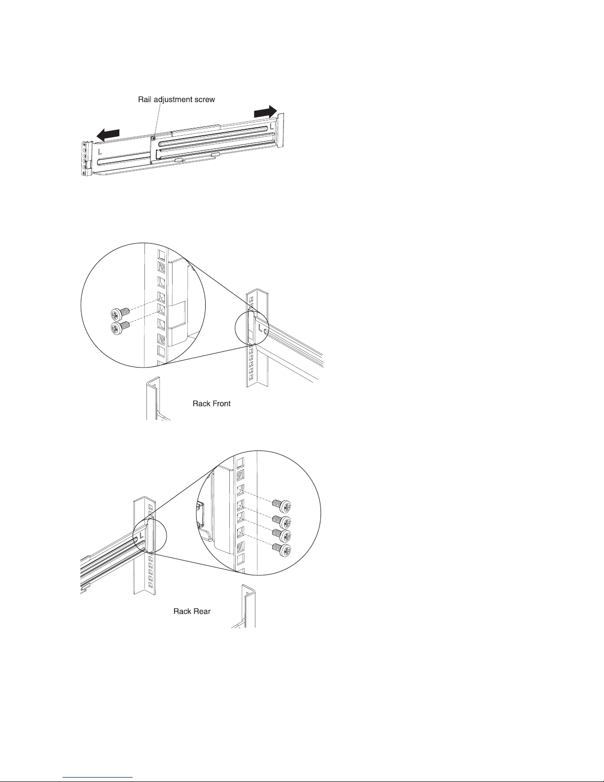
2. Loosen the rail adjustment screw and adjust the left and right rail length to the depth of the rack
cabinet.
3. Select a location in the bottom of the rack cabinet for the uninterruptible power supply or extended
battery module.
4. Secure each rail to the front of the rack with two M5 x 16 mm screws. Make sure that the rails are on
the inside of the rack-cabinet mounting flanges, and the letter on each rail faces inside the rack.
5. Secure each rail to the rear of the rack with four M5 x 16 mm screws.
6. Tighten the rail adjustment screws in the middle of each rail.
4
Page 5

7. For uninterruptible power supply installation only: To reduce the weight of the uninterruptible
power supply, remove the internal battery module:
a. Loosen the thumbscrew on the metal battery cover 1, slide the cover to the right 2, and open
the cover 3.
b. Using the plastic tabs, pull the battery module partially out of the bay.
1
0
0
%
1500
208
VA
V
6
/60hz
m
i
U
n
P
S
O
N
OKOK
6
in
m
100%
VA
1500
/60hz
V
208
UPS ON
OK
5
Page 6

c. See the following table to determine how many people are required to lift the internal battery
module. Some battery modules might require two people to lift it.
Table 1. Internal battery module handling requirements
Battery description Weight Handling requirement
1500 VA internal battery module 8 kg (18 lb) One person
2200 VA internal battery module 16.3 kg (36 lb) One person
3000 VA internal battery module 21.3 kg (47 lb) Two persons
d. With two hands pull the battery module fully out of the bay and place it on a sturdy, flat surface.
Note: The 3000 VA battery module requires two persons to handle it.
e. Close the metal battery cover 1, then slide the cover slightly to the right and then to the left
2. Tighten the thumbscrew 3.
If you are installing another uninterruptible power supply, repeat step 7 on page 5.
6
Page 7

8. The uninterruptible power supply and extended battery module are very heavy. See the following
table to determine the number of people that are required to install these devices.
Table 2. Uninterruptible power supply and extended battery module handling requirements
Machine
type-model or
part number Product description Weight Handling requirement
5395-1AX 1500 VA 2U rack
uninterruptible power supply
5395-1KX 1500 VA 2U rack
uninterruptible power supply
5395-2AX 2200 VA 2U rack
uninterruptible power supply
5395-2KX 2200 VA 2U rack
uninterruptible power supply
5395-3AX 3000 VA 3U rack
uninterruptible power supply
5395-3JX 3000 VA 3U rack
uninterruptible power supply
5395-3KX 3000 VA 3U rack
uninterruptible power supply
46M4108 Extended battery module for
2200 VA 2U uninterruptible
power supply
69Y1982 Extended battery module for
3000 VA 3U uninterruptible
power supply
10.2 kg (22.6 lb) (chassis only) One person
11.3 kg (25 lb) (chassis only) One person
14.2 kg (31.3 lb) (chassis only) One person
14.4 kg (31.7 lb) (chassis only) One person
17.2 kg (37.9 lb) (chassis only) One person
17.9 kg (39.4 lb) (chassis only) Two persons
19.6 kg (43.2 lb) (chassis only) Two persons
41.2 kg (90.8 lb) Three persons
52.2 kg (115.1 lb) Three persons
9. Align the rear hold down brackets on the sides of the uninterruptible power supply or extended
battery module with the inner rails. Carefully slide the uninterruptible power supply or extended
battery module into the rack cabinet.
10. Secure the front of the uninterruptible power supply or extended battery module to the rack cabinet
with four M5 x 16 mm screws.
7
Page 8

11. For uninterruptible power supply installation only: To reinstall the battery module, complete the
following steps:
a. Loosen the thumbscrew on the metal battery cover 1, slide the cover to the right 2, and open
the cover 3.
8
Page 9

b. With two hands (four hands for a 3000 VA battery module), carefully slide the battery module
into the uninterruptible power supply 1. For the number of people required to handle the
battery module, see the following table.
Table 3. Internal battery module handling requirements
Battery description Weight Handling requirement
1500 VA internal battery module 8 kg (18 lb) One person
2200 VA internal battery module 16.3 kg (36 lb) One person
3000 VA internal battery module 21.3 kg (47 lb) Two persons
Internal battery
connector
1
0
0
%
1500
208
VA
V
6
/60hz
m
in
U
P
S
O
N
OKOK
6
in
m
100%
VA
1500
/60hz
V
208
UPS ON
OKOK
c. Remove the internal battery connector from the holder on the metal battery cover; then, connect
the internal battery connector 2.
Note: A small amount of arcing might occur when you connect the batteries. This is normal and
does not damage the unit or present any safety concern.
9
Page 10

d. Close the metal battery cover 1, then slide the cover slightly to the right and then to the left
2. Tighten the thumbscrew 3.
12. Locate the bezel that comes with the uninterruptible power supply or extended battery module.
Press the two side latches toward each other, align the bezel with the uninterruptible power supply
or extended battery module, and snap it into place.
1
0
0
%
1500
208
VA
V
6
/60hz
m
i
U
n
P
S
O
N
OKOK
10
Page 11

13. Remove the clear protective film that covers the liquid crystal display (LCD) on the front of the
uninterruptible power supply.
For more information about installing and operating the uninterruptible power supply and extended
battery module, see the Installation and Maintenance Guide that comes with the uninterruptible power
supply.
Store this information with your uninterruptible power supply documentation for future use.
11
Page 12

Second Edition (May 2011)
IBM is a trademark of International Business Machines Corporation in the United States, other countries, or both.
Printed in USA
© Copyright IBM Corporation 2010, 2011.
US Government Users Restricted Rights – Use, duplication or disclosure restricted by GSA ADP Schedule Contract
with IBM Corp.
(1P) P/N: 60Y1453
 Loading...