

Page 1

IBM® xSeries 220
User’s Reference
IBM
SC06-P460-70
Page 2

First Edition (October 2000)
© Copyright International Business Machines Corporation 2000. All rights reserved.
US Government Users Restrict ed Righ ts – Use, dupli ca ti on or dis cl osu re restricted by GSA ADP Schedule Contract with
IBM Corp.
Page 3

Contents
Safety . . . . . . . . . . . . . . . . . . . . . . . . . . . . . v
Chapter 1.Introducing the IBM xSeries 2201
Features and specifications . . . . . . . . . . . . . . . . . . . . . . . . 2
Notices used in this book. . . . . . . . . . . . . . . . . . . . . . . . . . 3
What your xSeries 220 offers. . . . . . . . . . . . . . . . . . . . . . . 3
Reliability, availability, and serviceability features . . . . 4
Server controls and indicators. . . . . . . . . . . . . . . . . . . . . . 5
Turning on the server . . . . . . . . . . . . . . . . . . . . . . . . . . 7
Turning off the server . . . . . . . . . . . . . . . . . . . . . . . . . . 8
Chapter 2.Arranging your workspace . . . . 9
Comfort. . . . . . . . . . . . . . . . . . . . . . . . . . . . . . . . . . . . . . . . . 9
Glare and lighting . . . . . . . . . . . . . . . . . . . . . . . . . . . . . . . . 9
Air circulation . . . . . . . . . . . . . . . . . . . . . . . . . . . . . . . . . . . 9
Electrical outlets and cable lengths. . . . . . . . . . . . . . . . . 10
Chapter 3. Configuring your se rver . . . . . 11
Using the Configuration/Setup Utility program. . . . . 11
Starting the Configuration/Setup Utility program 11
Choices available from the Configuration/Setup main
menu . . . . . . . . . . . . . . . . . . . . . . . . . . . . . . . . . . . . . . . . . . 12
Using passwords . . . . . . . . . . . . . . . . . . . . . . . . . . . . . 15
Power-on password . . . . . . . . . . . . . . . . . . . . . . . . 15
Administrator password . . . . . . . . . . . . . . . . . . . . 16
Using the SCSISelect Utility program . . . . . . . . . . . . . . 17
Starting the SCSISelect Utility program . . . . . . . . . . 17
Choices available from the SCSISelect menu . . . . . 18
Using the PXE Boot Agent Utility program . . . . . . . . . 19
Starting the PXE Boot Agent Utility program . . . . . 19
Choices available from the PXE Boot Agent menu. 19
Chapter 4.Using the ServerGuide CDs . . 21
Features at a glance. . . . . . . . . . . . . . . . . . . . . . . . . . . . . . 21
Setup and configuration overview. . . . . . . . . . . . . . . . . 22
System Partition. . . . . . . . . . . . . . . . . . . . . . . . . . . . . . . . . 23
Typical NOS installation. . . . . . . . . . . . . . . . . . . . . . . . . . 23
Setting up or updating multiple servers . . . . . . . . . . . . 24
Installing your NOS without ServerGuide . . . . . . . . . . 24
Additional programs included with ServerGuide. . . . 25
Error symptoms. . . . . . . . . . . . . . . . . . . . . . . . . . . . . . . . . 25
Chapter 5.Installing options . . . . . . . . . . . 27
Major components of the xSeries 220 server. . . . . . . . . 27
System board . . . . . . . . . . . . . . . . . . . . . . . . . . . . . . . . . . . 28
System-board option connectors. . . . . . . . . . . . . . . . 28
System-board internal cable connectors. . . . . . . . . . 29
System-board external port connectors . . . . . . . . . . 29
System-board jumpers and switches . . . . . . . . . . . . 30
Before you begin . . . . . . . . . . . . . . . . . . . . . . . . . . . . . . . . 31
System reliability considerations. . . . . . . . . . . . . . . . 31
Handling static-sensitive devices . . . . . . . . . . . . . . . 31
Safety information. . . . . . . . . . . . . . . . . . . . . . . . . . . . 32
Rotating the stabilizing feet. . . . . . . . . . . . . . . . . . . . . . . 37
Removing the side cover . . . . . . . . . . . . . . . . . . . . . . . . . 38
Removing the support bracket assembly. . . . . . . . . . . . 39
Working with adapters. . . . . . . . . . . . . . . . . . . . . . . . . . . 40
Adapter considerations. . . . . . . . . . . . . . . . . . . . . . . . 40
Installing an adapter . . . . . . . . . . . . . . . . . . . . . . . . . . 41
Installing internal drives. . . . . . . . . . . . . . . . . . . . . . . . . . 44
Internal drive bays . . . . . . . . . . . . . . . . . . . . . . . . . . . . 44
Preinstallation steps (all bays) . . . . . . . . . . . . . . . . . . 45
Installing a drive in bay 1, 2, 3, or 4. . . . . . . . . . . . . . 46
Installing a non-hot-swap hard disk drive in bay 5, 6,
or 7 . . . . . . . . . . . . . . . . . . . . . . . . . . . . . . . . . . . . . . . . . . . . 48
Installing a hot-swap hard disk drive in bay 5, 6, or 7 .
49
Installing memory modules. . . . . . . . . . . . . . . . . . . . . . . 51
Installing and removing a microprocessor . . . . . . . . . . 54
Installing a microprocessor. . . . . . . . . . . . . . . . . . . . . 54
Removing a microprocessor. . . . . . . . . . . . . . . . . . . . 58
Installing the side cover . . . . . . . . . . . . . . . . . . . . . . . . . . 60
Connecting external options . . . . . . . . . . . . . . . . . . . . . . 61
Installation procedure . . . . . . . . . . . . . . . . . . . . . . . . . 61
I/O connector locations . . . . . . . . . . . . . . . . . . . . . . . . . . 61
Input/output ports . . . . . . . . . . . . . . . . . . . . . . . . . . . . . . 62
Parallel port. . . . . . . . . . . . . . . . . . . . . . . . . . . . . . . . . . 62
Viewing or changing the port assignments. . . . . 62
Parallel port connector. . . . . . . . . . . . . . . . . . . . . . 63
Serial ports. . . . . . . . . . . . . . . . . . . . . . . . . . . . . . . . . . . 63
Vi ewi ng o r changing the serial-port assignments 64
Serial-port connectors. . . . . . . . . . . . . . . . . . . . . . . 64
Universal Serial Bus ports. . . . . . . . . . . . . . . . . . . . . . 64
USB cables and hubs. . . . . . . . . . . . . . . . . . . . . . . . 64
USB-port connectors. . . . . . . . . . . . . . . . . . . . . . . . 65
Keyboard port. . . . . . . . . . . . . . . . . . . . . . . . . . . . . . . . 65
Auxiliary-device (pointing device) port. . . . . . . . . . 65
Video port . . . . . . . . . . . . . . . . . . . . . . . . . . . . . . . . . . . 66
SCSI port . . . . . . . . . . . . . . . . . . . . . . . . . . . . . . . . . . . . 67
SCSI cabling requirements. . . . . . . . . . . . . . . . . . . 67
Setting SCSI IDs. . . . . . . . . . . . . . . . . . . . . . . . . . . . 67
External SCSI devices. . . . . . . . . . . . . . . . . . . . . . . 67
SCSI connector pin-number assignments . . . . . . 68
Ethernet port. . . . . . . . . . . . . . . . . . . . . . . . . . . . . . . . . 69
Configuring the Ethernet controller. . . . . . . . . . . 69
Failover for redundant Ethernet. . . . . . . . . . . . . . 69
High-performance Ethernet modes . . . . . . . . . . . 69
Ethernet port connector . . . . . . . . . . . . . . . . . . . . . 72
Chapter 6.Solving problems. . . . . . . . . . . 73
Diagnostic tools overview . . . . . . . . . . . . . . . . . . . . . . . . 73
POST . . . . . . . . . . . . . . . . . . . . . . . . . . . . . . . . . . . . . . . . . . 75
POST beep code descriptions. . . . . . . . . . . . . . . . . . . 75
POST beep codes . . . . . . . . . . . . . . . . . . . . . . . . . . . . . 77
POST error messages. . . . . . . . . . . . . . . . . . . . . . . . . . 79
POST error log . . . . . . . . . . . . . . . . . . . . . . . . . . . . . . . 86
Small computer system interface messages. . . . . . . . . . 86
Diagnostic programs and error messages . . . . . . . . . . . 87
Text messages . . . . . . . . . . . . . . . . . . . . . . . . . . . . . . . . 88
Starting the diagnostic programs. . . . . . . . . . . . . . . . 88
Viewing the test log . . . . . . . . . . . . . . . . . . . . . . . . . . . 89
Diagnostic error message tables. . . . . . . . . . . . . . . . . 90
Recovering the BIOS code . . . . . . . . . . . . . . . . . . . . . . . . 97
Identifying problems using status LEDs . . . . . . . . . . . . 98
Front panel and system board LEDs. . . . . . . . . . . . . 98
Diagnostic LEDs. . . . . . . . . . . . . . . . . . . . . . . . . . . . . . 99
Troubleshooting charts . . . . . . . . . . . . . . . . . . . . . . . . . . 101
Troubleshooting the Ethernet controller. . . . . . . . . 106
Network connection problems . . . . . . . . . . . . . . 106
Ethernet controller troubleshooting chart. . . . . 106
Ethernet controller messages . . . . . . . . . . . . . . . . . . 108
© Copyright IBM Corp. 2000 iii
Page 4

Novell NetW a re or IntraNetWare server ODI driver
teaming messages. . . . . . . . . . . . . . . . . . . . . . . . . 108
NDIS 4.0 (Windows NT) driver messages . . . . 109
Replacing the battery . . . . . . . . . . . . . . . . . . . . . . . . . . . 113
Getting help, service, and information. . . . . . . . . . . . . 115
Getting information. . . . . . . . . . . . . . . . . . . . . . . . . . 115
Using the World Wide Web. . . . . . . . . . . . . . . . . 115
Getting information by fax . . . . . . . . . . . . . . . . . 115
Getting help and service. . . . . . . . . . . . . . . . . . . . . . 115
Using the documentation and diagnostic programs
115
Calling for service. . . . . . . . . . . . . . . . . . . . . . . . . 116
Other services . . . . . . . . . . . . . . . . . . . . . . . . . . . . 118
Purchasing additional services . . . . . . . . . . . . . . . . 118
Appendix A. Product warranties and
notices . . . . . . . . . . . . . . . . . . . . . . . . . . 119
Warranty Statements. . . . . . . . . . . . . . . . . . . . . . . . . . . . 119
IBM Statement of Limited Warranty for United States,
Puerto Rico, and Canada (Part 1 - General Terms) 119
IBM Statement of Warranty Worldwide except United
States, Puerto Rico, and Canada (Part 1 – General
Terms) . . . . . . . . . . . . . . . . . . . . . . . . . . . . . . . . . . . . . 122
Part 2 - Worldwide Country-Unique Terms . . . . . . 125
Notices. . . . . . . . . . . . . . . . . . . . . . . . . . . . . . . . . . . . . . . . 128
Edition notice . . . . . . . . . . . . . . . . . . . . . . . . . . . . . . . 128
Processing date data . . . . . . . . . . . . . . . . . . . . . . . . . 129
Trademarks . . . . . . . . . . . . . . . . . . . . . . . . . . . . . . . . . 129
Important notes . . . . . . . . . . . . . . . . . . . . . . . . . . . . . 130
Electronic emission notices . . . . . . . . . . . . . . . . . . . . . . 130
Federal Communications Commission (FCC)
Statement. . . . . . . . . . . . . . . . . . . . . . . . . . . . . . . . . . . 130
Industry Canada Class A emission compliance
statement . . . . . . . . . . . . . . . . . . . . . . . . . . . . . . . . . . . 131
Australia and New Zealand Class A statement. . . 131
United Kingdom telecommunications safety
requirement. . . . . . . . . . . . . . . . . . . . . . . . . . . . . . . . . 131
European Union EMC Directive conformance
statement . . . . . . . . . . . . . . . . . . . . . . . . . . . . . . . . . . . 131
Taiwan electrical emission statement . . . . . . . . . . . 132
Japanese Voluntary Control Council for Interference
(VCCI) statement . . . . . . . . . . . . . . . . . . . . . . . . . . . . 132
Power cords . . . . . . . . . . . . . . . . . . . . . . . . . . . . . . . . . . . 132
Index . . . . . . . . . . . . . . . . . . . . . . . . . . . . . 135
iv IBM® xSeries 220 User’s Refere nc e
Page 5
Safety
Before installing this product, read the Safety Information book .
Antes de instalar este produto, leia o Manual de Informações sobre Segurança.
Pred instalací tohoto produktu si prectete prírucku bezpecnostních instrukcí.
Læs hæftet med sikkerhedsforskrifter, før du installerer dette produkt.
Lue Safety Information -kirjanen, ennen kuin asennat tämän tuotteen.
Avant de procéder à l'installation de ce produit, lisez le manuel Safety Information.
Vor Beginn der Installation die Broschüre mit Sicherheitshinweisen lesen.
Przed zainstalowaniem tego produktu należy przeczytać broszurę Informacje Dotyczące
Bezpieczeństwa.
Prima di installare questo prodotto, leggere l'opuscolo contenente le informazioni
sulla sicurezza.
© Copyright IBM Corp. 2000 v
Page 6

Lees voordat u dit product installeert eerst het boekje met veiligheidsvoorschriften.
Les heftet om sikkerhetsinformasjon (Safety Information) før du installerer dette
produktet.
Antes de instalar este produto, leia o folheto Informações sobr e Segurança.
Перед установкой продукта прочтите брошюру по технике безопасности
(Safety Information).
Pred inštaláciou tohto produktu si pre ítajte Informa nú brožúrku o bezpe nosti.
Preden namestite ta izdelek, preberite knjižico Varnostne informacije.
Antes de instalar este producto, lea la Información de Seguridad.
Läs säkerhetsinformationen innan du installerar den här produkten.
Installálás el tt olvassa el a Biztonsági el írások kézikönyvét !
vi IBM® xSeries 220 User’s Reference
Page 7
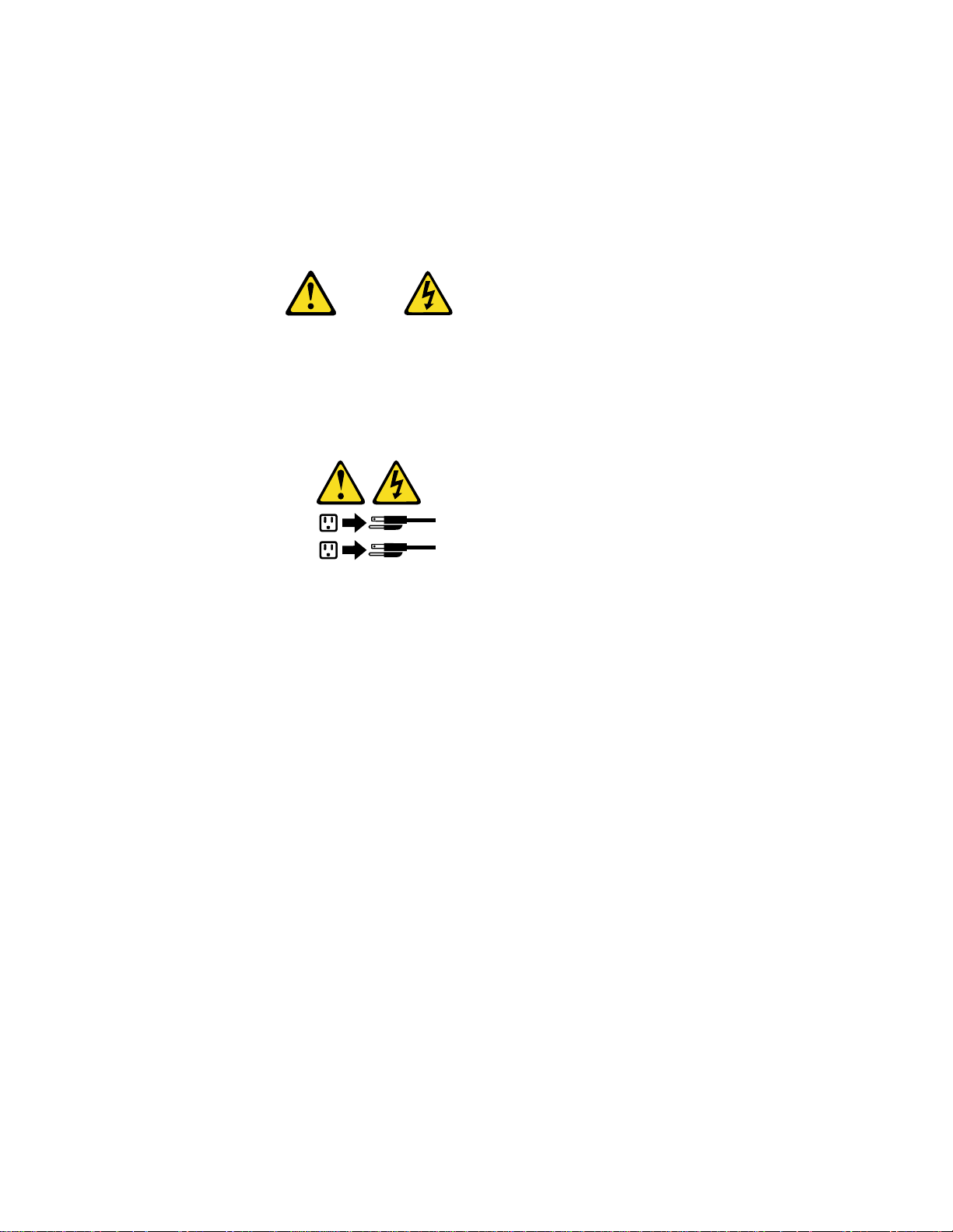
Statement 1
Danger
Electrical current from power, telephone, and communication cables is
hazardous.
To avoid a shock hazard:
• Do not connect or disconnect any cables or perform installation,
maintenance, or reconfiguration of this product during an electrical storm.
• Connect all power cords to a properly wired and grounded electrical outlet.
• Connect to properly wired outlets any equipment that will be attached to
this product.
• When possible, use one hand only to connect or disconnect signal cables.
• Never turn on any equipme nt when there is evidence of fire, water, or
structural damage.
• Disconnect the attached power cords, telecommunications systems,
networks, and modems before you open the device covers, unless instructed
otherwise in the installation and configuration procedures.
• Connect and disconnect cables as described in the following table when
installing, moving, or opening covers on this product or attached devices.
To connect:
1. Turn everything OFF.
2. First, attach all cables to devices.
3. Attach signal cables to connectors.
4. Attach power cords to outlets.
5. Turn device ON.
To disconnect:
1. Turn everything OFF.
2. First, remove power cords from
outlets.
3. Remove signal cables from
connectors.
4. Remove all cables from devices.
vii
Page 8
Statement 2
CAUTION:
When replacing the lithium battery, use only IBM Part Number 33F8354 or an
equivalent type battery recommended by the manufacturer. If your system has a
module containing a lithium battery, replace it only with the same module type
made by the same manufacturer. The battery contains lithium and can explode if
not properly used, handled, or disposed of.
Do not:
• Throw or immerse into water.
• Heat to more than 100 C (212 F)
• Repair or disassemble
Dispose of the battery as required by local ordinances or regulations.
Statement 3
CAUTION:
When laser products (such as CD-ROMs, DVD drives, fiber optic devices, or
transmitters) are installed, note the following:
• Do not remove the covers. Removing th e covers of the laser product could
result in exposure to hazardous laser radiation. There are no serviceable
parts inside the device.
• Use of controls or adjustments or performance of procedures other than
those specified herein might result in hazardous radiation exposure.
Danger
Some laser products contain an embedded Class 3A or Class 3B laser diode. Note
the following. Laser radiation when open. Do not stare into the beam, do not view
directly with optical instruments, and avoid direct exposure to the beam.
viii IBM® xSeries 220 User’s Reference
Page 9
Statement 4
≥18 kg (39.7 lbs)
≥32 kg (70.5 lbs)
≥55 kg (121.2 lbs)
CAUTION:
Use safe practices when lifting.
Statement 5
CAUTION:
The power control button on the device and the power switch on the power
supply do not turn off the electrical current supplied to the device. The device
also might have more than one power cord. To remove all electrical current from
the device, ensure that all power cords are disconnected from the power source.
2
1
ix
Page 10

x IBM® xSeries 220 User’s Reference
Page 11
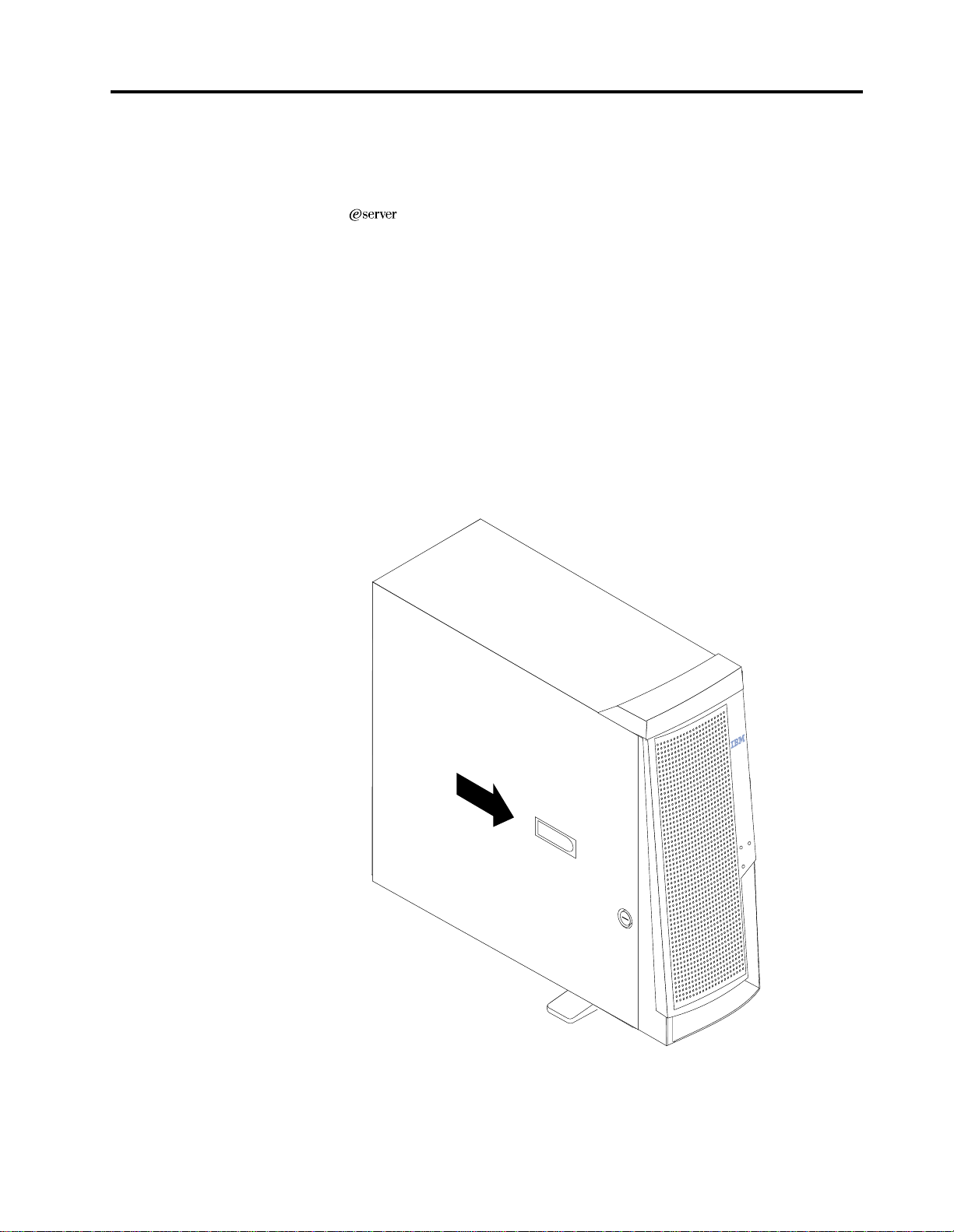
Chapter 1. Introducing the IBM xSeries 220
Your IBM
®
xSeries 220 delivers great value for entry server applications. It is
ideally suited for networking environments that require superior microprocessor
performance, efficient memory management, flexibility , and lar ge amounts of reliable
data storage.
Y our IBM xSeries 220 server comes with a three-year limited warranty and IBM Server
Start Up Support. If you have access to the World Wide Web, you can obtain up-todate information about your xSeries 220 model and oth e r IBM server products at the
following World Wide Web address: http://www.ibm.com/eserver/xseries
For service, assistance, or additional information on IBM Server Start Up Support and
the World Wide Web, see “G etting help, service, and information” on page 115.
The server serial number and model number are located on labels on the rear and the
right front of the server. You wi ll need th ese numbers when you register your server
with IBM.
© Copyright IBM Corp. 2000 1
Page 12

Features and specifications
Table 1 provides a summary of the features and specifications of your xSeries 220
server.
Microprocessor:
• Intel® Pentium® III
microprocessor with MMX™
technology and SIMD
extensions
• 256 KB* ECC, level-2 cache
(min.)
• 133 MHz front-side bus (FSB)
• Support for up to two
microprocessors
Memory:
• Standard: 128 MB*
• Maximum: 4 GB*
• Type: 133 MHz, EC C , SDR AM ,
registered DIMMs
• Slots: 4 dual in-line
Drives standard:
• Diskette: 1.44 MB
• CD-ROM: 48X IDE
• Supports hot-swap SCSI hard
disk drives (some models)
Expansion bays:
• Two 5.25-in. bays (one CD-ROM
drive installed)
• Two 3.5-in. bays (one diskette
drive installed)
• Three 3.5-in. slim bays available
in drive cage (some models
have a hard disk drive installed)
PCI expansion slots:
• Three 33 MHz/64-bit
• Two 33 MHz/32-bit
Power supply:
One 330 watt autosensing (115-230 V
ac)
Video:
• S3 video controller (integrated
on system board)
• Compat ib le with SVGA and
VGA
• 8 MB SDRAM video memory
Size:
• Height: 470 mm (18.5 in.)
• Depth: 508 mm (20 in.)
• Width: 165 mm (6.5 in.)
• Weight: appr oximately 19.5 Kg
(43 lb.) when fully configured
or 15.9 Kg (35 lb.) minimum
Integrated functions:
• Ultra160 SCSI low voltage
differential (LVD) controller
• One 10BASE-T/100BASE-TX
Intel Ethernet cont r oller on the
system board
• Two s erial ports
• Parallel port
• Two Universal Serial Bus
(USB) ports
• Keyboard port
• Mo use port
• IDE controller port
• Video port
Acoustical noise emissions:
• Sound power, idling: 5.1 bel
maximum
• Sound power, operating: 5.3
bel maximum
Environment:
• A i r temperature:
— Server on: 10° to 35° C (50.0°
to 95.0° F). Altitude: 0 to 914
m (2998.7 ft)
— Server on: 10° to 32° C (50.0°
to 89.6° F). Altitude: 914 m
(2998.7 ft) to 2 133 m (6998.0
ft)
— Server o ff: 10° to 43 ° C (50.0°
to 109.4° F). Maximum
altitude: 2133 m (6998.0 ft)
• Humidity:
— Server on: 8% to 80%
— Server off: 8% to 80%
Heat output:
Approximate heat output in British
thermal units (Btu) per hour
• Minimum configuration: 341 Btu
(100 watts)
• Maximum configuration: 1604
Btu (470 watts)
Electrical input:
• Sine-wave input (50-60 Hz)
required
• Input voltage low range:
— Minimum: 100 V ac
— Maximum: 127 V ac
• Input voltage high range:
— Minimum: 200 V ac
— Maximum: 240 V ac
• Input kilovolt-amperes (kVA),
approximately:
— Minimum: 0.08 kVA
— Maximum: 0.52 kVA
Table 1. Features and specifications
*KB equals approximately 1000 bytes. MB equals approximately 1000000 bytes. GB
equals approximately 1000000000 bytes.
2 IBM® xSeries 220 User’s Referen ce
Page 13

Notices used in this book
The caution and danger notices also appear in the multilingual Safety Information book
provided on the IBM xSeries Documentat io n CD that comes with your xSeries product.
Each notice is numbered for easy reference to the corresponding notices in the safety
book.
The following types of notices are used in this book:
• Note: These notices provide important tips, guidance, or advice.
• Important: These notices provide information or advice that might help you
avoid inconvenient or problem situations.
• Attention: These notices indicate possible damage to programs, devices, or data.
An attention notice is placed just before the instruction or situation in which
damage could occur.
• Caution: These notices indicate situations that can be potentially ha zardous to
you. A caution notice is placed just before the description of a potentially
hazardous procedure step or situation.
• Danger: These notices indicate situation s that can be potentially lethal or
extremely hazardous to you. A danger notice is placed just before the
description of a potentially lethal or extremely hazardous procedure step or
situation.
What your xSeries 220 offers
The design of your server takes advantage of advancements in symmetric
multiprocessing (SMP), data storage, and memory management. Your server
combines:
• Impressive performance using an innovative approach to SMP
Your server supports up to two Pentium III microprocessors. Your server comes
with one microprocessor installed; you can install an additional microprocessor
to enhance performance and provide SMP capability.
• Large system memory
The memory bus in your server supports up to 4 GB of system memory. The
memory controller provides error correcting code (ECC) support for up to four
industry-standard PC133, 3.3 V,168-pin, 8-by t e, registered, synchronousdynamic-random access memory (SDRAM) dual in-line memory modules
(DIMMs).
• System-management capabilities
You can use the system-management software that is included with your server
to manage the functions of the server locally and remotely. Refer to the
documentation that comes with your system-management software for more
information.
• Integrated network environment support
Your server comes with an Ethernet controller on the system board. This
Ethernet controller has an interface for connecting to 1 0- Mbps or 100-Mbps
networks. The server automatically selects between 10BASE-T and 100BASE-TX
environments. The controller provides full-duplex (FDX) capability, which
allows simultaneous transmission and reception of data on the Ethernet local
area network (LAN).
Chapter 1. Introducing the IBM xSeries 220 3
Page 14

• IBM ServerGuide™ CDs
The ServerGuide CDs that are included with your server provide programs to
help you set up your server and install the network operating system (NOS).
The ServerGuide program detects the hardware options that are installed and
provides the correct configuration pr ograms a nd device drivers. In addition, the
ServerGuide CDs include a variety of application programs for your server.
For more information about the ServerGuide CDs, see “Chapter 4. Using the
ServerGuide CDs,” on page 21.
Reliability, availability, and serviceability features
Three of the most important considerations in server design are r eliability, availability,
and serviceability (RAS). The RAS features help to ensur e the integrity of the data that
is stored on your server, the availability of the server when you need it, and the ease
with which you can diagnose and repair problems.
The following is an abbreviated list of the RAS features that your server supports:
• Automatic restart after a power failure
• Customer support center 24 hours a day, 7 days a week
• Cyclic redundancy check (CRC) checking on the small computer system
interface (SCSI) buses
• Diagnostic light-emitting d iodes (LEDs)
• Error checking and correcting (ECC) memory
• Error codes and messages
• Menu-driven setup, system configuration, optional redundant array of
independent disks (RAID) configuration, and diagnostic programs
• Optional system-management adapter subsystem to provide control for remote
system management
• Optional Wake on LAN
adapter)
• Power and temperature monitoring
• Power-on self-test (POST)
• Processor serial number access
• System error logging (POST)
• Upgradeable basic input/output system (BIOS) and diagnostics
• Vital product data (VPD) on memory, system board, and hot-swap drive
backplane
®
(WOL) function through network-interface card (NIC
1
1. Service availability will vary by count r y. Response time will vary depending on the numbe r and nature of incoming calls.
4 IBM® xSeries 220 User’s Referen ce
Page 15
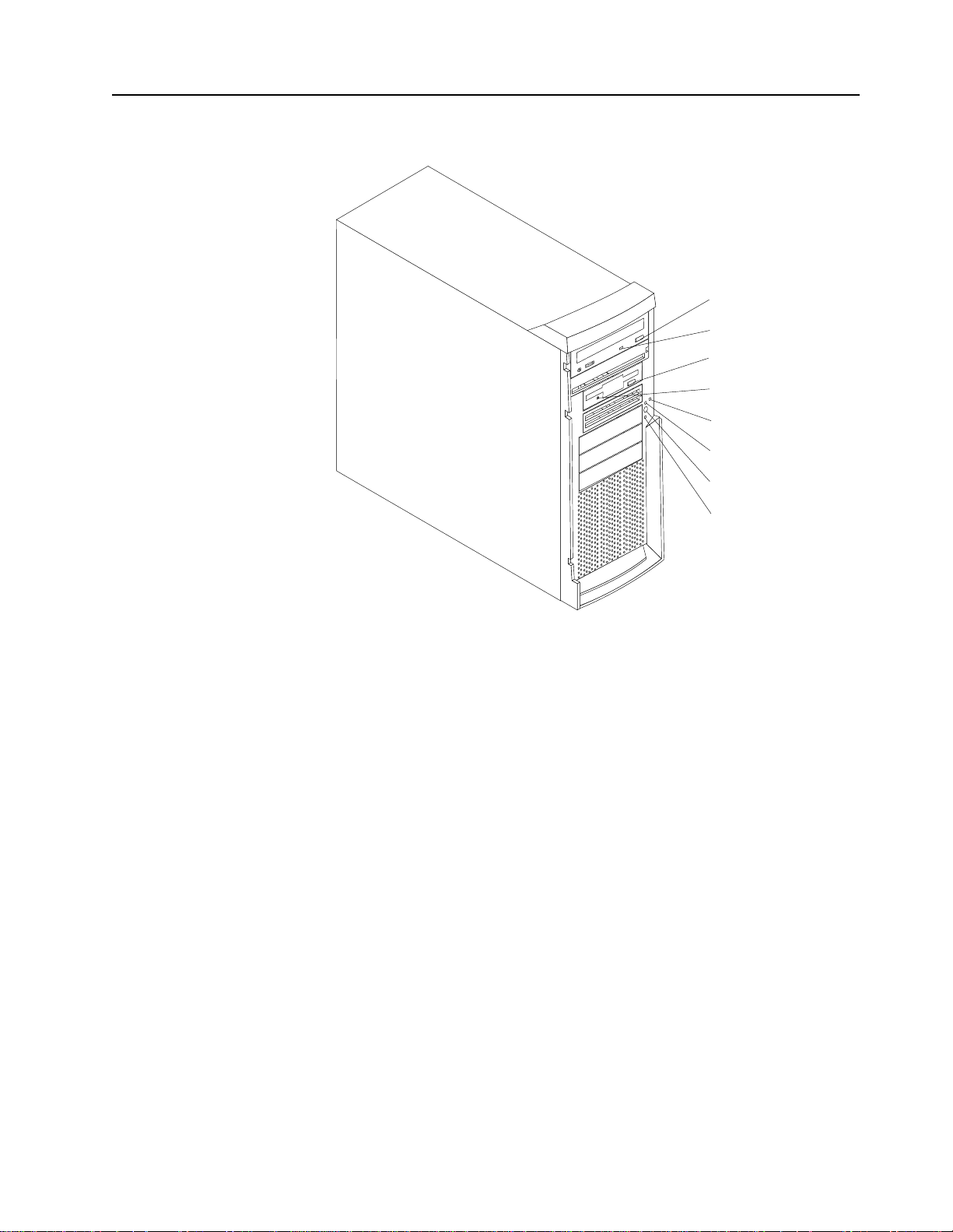
Server control s a nd indicators
This section identifies the controls and indicators on the front of your server.
CD-ROM
eject button
CD-ROM drive
activity light
Diskette-eject
button
Diskette drive
activity light
SCSI
activity light
Power-on
light
Power-control
button
System error
light
CD-ROM eject button: Press this button to release a CD from the drive.
CD-ROM drive activity light: When this light is on, it indicates that the CD-ROM
drive is in use.
Diskette-eject button: Press this button to release a diskette from the drive.
Diskette-drive activity light: When this light is on, it indicates that the diskette drive
is in use.
SCSI activity light: When this green light is flashing, the controller is accessing a SCSI
device; for example, a hard disk drive.
Note: Hot-swap hard disk drives also have an activity light. This light is also known
as the SCSI hard disk drive activity light.
If your server has a ServeRAID™ controller and this light flashes slowly (one flash per
second), the drive is being rebuilt. When the light flashes rapidly (three flashes per
second), the controller is identifying the drive.
Power-on light: When this green light is on, system power is present in the server.
Power-control button: Press this button to manually turn the server on or off.
System error light: When this amber light is on, it indicates that a system error has
occurred. An amber error light on the interior of the server, adjacent to the faulty
component, will also be on to further isolate the error. (For more information, see
“Chapter 6. Solving problems,” on page 73.)
Chapter 1. Introducing the IBM xSeries 220 5
Page 16
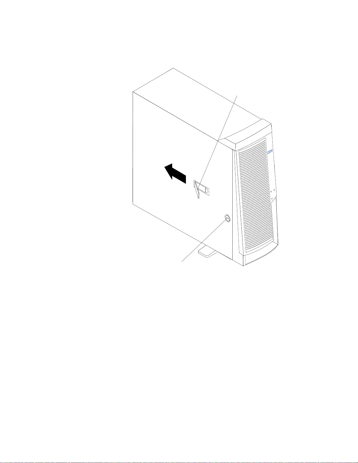
Cover-release latch: Slide this lever to release the cover.
Key lock:Use the key that comes with your server to unlock the cover.
Cover-release
latch
Key lock
6 IBM® xSeries 220 User’s Referen ce
Page 17

Turning on the server
Turning on the server refers to the act of plugging the power cord of your server into
the power source and starting the operating system.
After you plug the power cord of your server into the power supply and an electrical
outlet, the server can start in any of the following ways:
• You can press the power-control button on the front of the server to start the
server.
Notes:
1. You can install a circular disk over the power-control button to prevent
accidental manual power-off. This disk, known as the power-control button
shield, comes with your server.
2. After you plug the power cord of your server into an electrical outlet, wait
approx imat ely 20 sec on ds b efo r e pr es sin g the p owe r -c ont r ol butt on. Dur in g
this time, the system is initializing; ther efore, the power-control button does
not respond.
• If the server is turned on and a power failure occurs, the server will start
automatically when power is restored.
• The Wake on LAN feature will turn on the server at the set time (when a Magic
Packet is received), provided that all of the following conditions a re met:
— AC pow e r is presen t .
— The server is either off or shut down from an Advanced Configuration and
Power Interface (ACPI) operating system.
— The Wake on LAN feature is enabled in the Configuration/Setup Utility
program.
— The Wake on LAN adapter is installed in PCI slot 1 and is connected to the
system board with the 3-pin auxiliary power connector.
Notes:
1. See “Choices available from the Configuration/Setup main menu” on page
12 for a description of the Configuration/Setup Utility program.
2. See “System-board option connectors” on page 28 for connector locations.
3. For additional information o n the Wake on LAN function, adapters, and
cables, refer to the documentation that comes with the adapters.
4. See “Ethernet port” on page 69 for information on Ethernet controllers and
adapters, and Wake on LAN adapters.
• If the optional system-management adapter is installed in your server, the
system-management adapter can turn on the server.
Chapter 1. Introducing the IBM xSeries 220 7
Page 18
Tu rning off the server
Turning off the server refers to the act of disconnecting the server from the power
source.
You can turn off the server in any of the following ways:
Statement 5
CAUTION:
The power control button on the device and the power switch on the power
supply do not turn off the electrical current supplied to the device. The device
also might have more than one power cord. To remove all electrical current from
the device, ensure that all power cords are disconnected from the power source.
2
1
• You can press the power-control button on the top of the server. This starts an
orderly shutdown of the operating system, if this feature is supported by your
operating system.
Note: After turning off the server, wait at least five seconds before you press
the power-control button to turn on the server again.
• You might need to press and hold the power-control button for more than four
seconds to cause an immediate shutdown of the server and to force the power
off. You can use this feature if the operating system stops functioning.
• You can disconnect the server power cords from the electrical outlets to shut off
all power to the server.
Note: After disconnecting the power cords, wait approximately 15 seconds for
your system to stop running. Watch for the power-on light to stop
blinking.
8 IBM® xSeries 220 User’s Referen ce
Page 19

Chapter 2. Arranging your workspace
To get the most from your server, arrange both the equipment you use and your work
area to suit your needs and the kind of work you do. Your comfort is of foremost
importance, but light sources, air circulation, and the location of electrical outlets also
can affect the way you arrange your workspace.
Comfort
Although no single working position is ideal for everyone, here are a few guidelines
to help you find a position tha t suits you best.
Sitting in the same position for a long time can cause fatigue. A good chair can make a
big difference. The backrest and seat should adjust independently and provide good
support. The seat should have a curved front to relieve pressure on the thighs. Adjust
the seat so that your thighs are parallel to the floor and your feet are either flat on the
floor or on a footrest.
When using the keyboard, keep your for earms parallel to the floor and your wrists in
a neutral, comfortable position. Try to keep a light touch on the keyboard and your
hands and fingers relaxed. You can change the angle of the keyboard for maximum
comfort by adjusting the position of the keyboard feet.
Adjust the monitor so the top of the screen is at, or slightly below, eye level. Place the
monitor at a comfortable viewing distance, usually 51 to 61 cm (20 to 24 in.), and
position it so you can view it without having to twist your body. Also position other
equipment you use regularly, such as the telephone or a mouse, within easy reach.
Glare and lighting
Position the monitor to minimize glare and reflections from overhead lights,
windows, and other light sources. Even reflected light from shiny surfaces can cause
annoying reflections on your monitor screen. Place the monitor at right angles to
windows and other light sources, when possi ble. Red uce overhead lighting, if
necessary, by turning off lights or using lower wattage bulbs. If you install the
monitor near a window, use curt ains or blinds to block the sunlight. You might have
to adjust the Brightness and Contrast controls on the mon itor as the room lighting
changes throughout the day.
Where it is impossible to avoid reflections or to adjust the lighting, an antiglare filter
placed over the screen might be helpful. However, these filters might affect the clarity
of the image on the screen; try them only after you have tried all other methods of
reducing glare.
Dust buildup compounds problems that are associated with glare. Remember to clean
your monitor screen periodically using a soft cloth that is moistened with a
nonabrasive liquid glass cleaner.
Air circulation
Your server and monitor produce heat. Your server has one or more fans that pull in
fresh air and force out hot air . The monitor lets hot air escape through vents. Blocking
the air vents can cause overheating, which might result in a malfunction or dama ge.
© Copyright IBM Corp. 2000 9
Page 20

Place the server and monitor so that nothing blocks the air vents; usually, 15 cm (6
inches) of air space is sufficient. Also, make sure that the vented air is not blowing on
someone else.
Electrical outlets and cable lengths
The location of electrical outlets and the length of power cords and cables that connect
to the monitor, printer, and other devices might determine the final placement of your
server.
When arranging your workspace:
• Avoid the use of extension cords. When possible, plug the server power cords
directly into electrical outlets.
• Keep power cords and cables neatly routed away from walkways and other
areas where they might get kicked accidentally.
For more information about power cords, refer to the power cord information in this
on-line publication.
10 IBM® xSeries 220 User’s Reference
Page 21

Chapter 3. Configuring your server
The following configuration programs are provided with your server:
• Configuration/Setup Utility
This pro gra m is par t of th e basic input/output system (BIOS) code that comes with
your server. You can use this program to configure serial and parallel port
assignments, change interrupt request (IRQ) settings, change the drive startup
sequence, set the date and time, and set passwords. See “Using the
Configuration/Setup Utility program” for more information.
• SCSISelect Utility
With the built-in SCSISelect Utility program, you can configure the devices that
are attached to the integrated SCSI controller. See “Using the S CSISe lect Utility
program” on page 17 for more information.
• PXE Boot Agent Utility
The Preboot eXecution Environment (PXE) Boot Agent Utility program is part of
the BIOS code that comes with your server. You can use this program to change
network startup (boot) protocols and startup (boot) order, to select operating
system wake up support, and to set menu wait times. See “Using the PXE Boot
Agent Utility program” on page 19 for more information.
• ServerGuide CDs
The ServerGuide CDs include software setup and installatio n tools that are
specifically designed for IBM xSeries servers. Yo u can use these CDs during the
initial installation of your server to conf igure the server hardware and simplify
your network operating system installation. The ServerGuide CDs also contain a
collection of application programs, which you can install after your server is up
and running. See “Chapter 4. Using the ServerGuide CDs,” on page 21 for more
detailed in formation.
• ServeRAID programs
The ServeRAID programs come with the optional ServeRAID adapters. If your
server has a ServeRAID adapter installed, you must use the ServeRAID
Configuration program to define and configure your disk-array subsystem before
you install your operating system.
Using the Configuration/Setup Utility program
This section provides instructions for starting the Configuration/Setup Utility
program and descriptions of the menu choices that are available.
Starting the Configuration/Setup Utility program
To start the Configuration/Setup Utility program, do the follow ing:
1. Turn on the server and watch the monitor screen.
2. When the message Press F1 for Configuration/Setup appears, press F1.
© Copyright IBM Corp. 2000 11
Page 22

Notes:
a. You can set an administrator password through the Configuration/Setup
Utility program only if the optional system-m anagement adapter is installed
in your server.
b. If you have set both levels of passwords (user and administrator), you must
type the administrator password to access the full Configurati on/Setup
Utility menu.
3. Follow the instructions that appear on the screen.
Choices available from the Configuration/Setup main
menu
From the Configuration/Setup Utility main menu, you can select settings that you
want to change. The Configuration/Setup U tility main menu is similar to the
following:
IBM - © IBM Corporation 2000
Configuration/Setup Utility
•
System Summary
•
System Information
•
Devices and I/O Ports
•
Date and Time
•
System Security
•
Start Options
•
Advanced Setup
•
Error Logs
Save Settings
Restore Settings
Load Default Settings
Exit Setup
<F1> Help < > < > Move
<Esc> Exit <Enter> Select
↑↓
Notes:
1. You can press F1 to display help information for a selected menu item.
2. The choices on some menus might differ slightly from the ones that are described
in this book, depending on the BIOS version in your server.
Descriptions of the choices that are available from the main menu are as follows:
• System Summary
Select this choice to display configuration information. This includes the type
and speed of the microprocessors and the amount of memory that is installed.
Changes that you make to configuration settings appear on this summary
screen. You cannot edit the fields.
This choice appears on both the full and limited Configuration/Setup Utility
menus.
• System Information
Select this choice to display informat ion about your server. Changes that you
make on other menus might appear on this summary screen. You cannot edit
any fields. The System Information choice a ppears only on the full
12 IBM® xSeries 220 User’s Reference
Page 23

Configuration/Setup Utility main menu.
— Product Data
Select this choice to view system information, such as the machine type and
model, the server serial number, and the revision level or issue date of the
BIOS that is stored in the flash electrically erasabl e p rogramma b le ROM
(EEPROM).
• Devices and I/O Ports
Select this choice to view or change the assignments for devices and
input/output ports. This choice appears only on the full Configuration/Setup
Utility main menu.
• Date and Time
Select this choice to set the system date and time.
The system time is in a 24-hour format (hour:minute:second).
• System Security
Select this choice to set passwords. This choice appears only on the full
Configuration/Setup Utility main menu.
You can implement two levels of password protection:
— Power-on Password
Select this choice to set or change a power-on password. See “Using
passwords” on page 15 for more information.
— Administrator Password
Note: This choice is available on the Configura tion/Setup Utility menu
only if the optional system-management adapter is installed in your
server.
Select this choice to set or change an administrator password.
Attention: If an administrator password is set and then forgotten, it cannot
be overridden or removed. You must replace the system board.
The administrator password provides access to all choices on the
Configuration/Setup Utility main menu. You can set, change, or delete both
the administrator and power-on passwords, and allow a power-on
password to be changed by the user.
See “Using passwords” on page 15 for more information.
• Start Options
Select this choice to view or change the start options. Start options take effect
when you start your server.
You can select keyboard operating characteristics, such as the keyboard speed.
Y ou also can specify whether the server starts with the keyboard number lock on
or off, and you can enable the server to run without a diskette drive, monitor, or
keyboard.
The server uses a startup sequence to determine the device from which the
operating system starts. For example, you can define a startup sequence that
checks for a startable diskette in the diskette drive, then checks the hard disk
drive in bay 1, and then checks a network adapter.
If you have the appropriate Ethernet adapter and Wake on LAN software
installed and enabled in the server, the server uses the alternative startup
sequence instead of the primary startup sequence. The default fo r Wake on LAN
is Disabled.
If the
Boot Fail Count choice is enabled, you can restore the BIOS system defaults
after three consecutive boot failures. If this choice is disabled, the BIOS system
Chapter 3. Configuring your serv er 13
Page 24

defaults can only be loaded from the Configura tion/Setup Utility main menu.
You can enable a virus-detection test that checks for changes in the master boot
record at startup. You also can select to run POST in the enhanced mode or the
quick mode.
• Advanced Setup
Select this choice to change values for advanced hardware features, such as
cache control and PCI configuration.
A message appears above the choices on this menu to alert you that the system
might malfunction if these options are configured incorrectly. Follow the
instructions on the screen carefully.
— Processor Serial Number Access
Select this choice to specify whether the microprocessor serial number in the
microprocessor is readable.
— System Partition Visibility
Select this choice to specify whether the System Partition is visible. To make
the System Partition visible, set this value to Visible. To make the System
Partition invisible, set this value to Hidden. See “Chapter 4. Using the
ServerGuide CDs,” on page 21 for additional information on the System
Partition.
— Core Chipset Control
Select this choice to modify settings that control features of the core chip set
on the system board.
Attention: Do not make changes in this option unless directed to do so by
an IBM authorized service representative.
— Cache Control
Select this choice to enable or disable the microprocessor cache. In addition,
you can define the microprocessor cache type as write-back (WB) or writethrough (WT). Selecting write-back mode provides better system
performance.
— Memory Settings
Select this choice to manually disable or enable a bank of memory.
If a memory error is detected during POST or memory configuration, the
server can automatically disable the fa iling memory bank and continue
operating with reduced memory capacity. If this occurs, you must manually
enable the memory bank after the problem is corrected. Select Memory
Settings from the Advanced Setup menu, use the arrow keys to highlight
the bank that you want to enable; then, use the arrow keys to select Enable.
Note: If a memory error is detected during normal operation, System
Management In t er rupt (SMI) can disa ble th e memo r y.
— PCI Bus Control
Note: If the optional system-management adapter is installed in your
server, this feature is disabled; in this case, the PCI Bus Control
choice is not available on the Configuration/Setup Utility menu.
Select this choice to assign IRQs and program the master latency timer.
— PCI Slot/Device Information
Note: This choice is available on the Configura tion/Setup Utility menu
only if the optional system-management adapter is installed in your
server.
Select this choice to view and identify system resources that are used by PCI
devices. PCI devices automatically communicate with the server
14 IBM® xSeries 220 User’s Reference
Page 25

configuration information. This usually results in automatic configuration of
a PCI device.
Attention: You must use the menu selections to save custom settings for the
PCI Slot/Device Information choice. The Save Settings, Restore Settings,
and Load Default Settings choices on the main menu of the
Configuration/Setup Utility do not save the PCI Slot/Device Information
settings.
After making changes, select:
– Save and exit the PCI Utility to save the changes and return to the
Advanced Setup choice.
– Exit the PCI Utility withou t saving changes to discard the changes,
retain the current settings, and return to the Advanced Setup choice.
• Error Log
Select this choice to view or clear error logs.
— Select POST Error Log to view the three most recent error codes and
messages that the system generated during POST.
— Select Clear error logs to clear the error logs.
• Save Settings
Select this choice to save your customized settings.
• Restore Settings
Select this choice to discard your changes and retain the current settings.
• Load Default Settings
Select this choice to discard your changes and restore the factory settings.
• Exit Setup
If you have made any changes, the program will prompt you to save the changes
or exit without saving the changes.
Using passwords
The System Security choice appears only on the full Configuration/Setup Utility
menu. After you select this choice, you can implement two levels of password
protection: power-on password and administrator password.
Power-on password
Select this choice to set a power-on password.
You can use any combination of up to seven characters (A–Z, a–z, and 0–9) for your
power-on password. Keep a record of your password in a secure place. If you forget
the power-on password, you can regain access to the server through one of the
following methods:
• If an administrator password has been set, enter the administrator password at
the power-on prompt. (If necessary, see “Administra tor password” on page 16
for details.) Start the Configuration/Setup Utility program and change the
power-on password.
• Start the Configuration/Setup Utility program, and change the power-on
password.
• Change the position of the password-override switch as described in “Setting
the password-override switch”.
Chapter 3. Configuring your serv er 15
Page 26
• Remove the battery and then reinstall the battery.
Setting the password-override switch: The following illustration shows the location
of the password-override switch (switch 8, which is the switch farthest to the right, on
switch block 1) on the system board.
Power-on
password-override
switch (switch 8 of
switch block 1)
To set the password-override switch, do the following:
1. Review the information in “Before you begin” on page 31.
2. Turn off the server and peripheral devices and disconnect all external cables and
power cords; then, remove the cover. See “Removing the side cover” on page 38.
3. Change the setting of the password-override switch (switch 8 on switch block 1
on the system board) to the opposite side of the switch. This bypasses the poweron password.
4. Install the server cover (see “Installing the side cover” on page 60) and connect all
external cables and power cords.
5. Restart the server .
Notes:
1. If you want the server to prompt for a password when you turn it on, you can
start the Configuration/Setup Utility program and set th e power-on password.
2. Changing the position of the password-override switch does not affect the
administrator password check if an ad ministrator password has been set.
Administrator password
Note: This choice is available on the Configuration/Setup Utility menu only if the
optional system-management adapter is installed in your server.
Select this choice to set an administrator password. The administrator password
provides access to all choices on the Configuration/Setup Utility main menu. You can
set, change, or delete both the administrator and power-on passwords, and allow a
power-on password to be changed by the user.
Attention: If an administrator password is set and then forgotten, it cannot be
overridden or removed. You must replace the system board.
The following table provides a summary of the password features.
16 IBM® xSeries 220 User’s Reference
Page 27

Type of password Results
Power-on password • Enter the password to complete the system star tu p .
• All choices are available on the Configuration/Setup Utility
main menu.
Administrator
password
Administrator and
power-on password
• No password is required to start the system.
• Enter the password to access the Configurat ion/Set up Utility
program.
• All choices are available on the Configuration/Setup Utility
main menu.
• You can enter either password to comple te the system
startup.
• The administrator password provides ac ce ss to al l choic es on
the Configuration/Setup Utility main menu. You can set,
change, or delete both the administrator and power-on
passwords, and a llow a power -on pas sword to be chang ed by
the user .
• The power-on password provides access to a limited set of
choices on the Configuration/Setup Utility main menu. This
limited access might include changing or deleting the poweron password.
Table 2. Power-on and administrator password features
Using the SCSISelect Utility program
SCSISelect is a built-in, menu-driven configuration utility program that you can use
to:
• View the default SCSI IDs
• Locate and correct configuration conflicts
The following sections provide instructions for starting the SCSISelect Utility and
descriptions of the menu choices that are available.
Note: If your server has a RAID adapter installed, use the configuration method
that is supplied with the RAID adapter to view or change SCSI settings for
devices attached to the adapter.
Starting the SCSISelect Utility program
Complete the following steps to start the SCSISel ect Uti lity program:
1. Turn on the server.
2. When the <<< Press <CTRL><A> for SCSISelect™ Utility! >>> pr ompt appears,
press Ctrl+A.
3. When the Would you like to configure the host adapter or run the SCSI
disk utility? question appears, make your selection and press Enter.
4. Use the arrow keys to select a choice from the menu:
• Press Esc to return to the previous menu.
• Press the F5 key to switch between color and monochrome modes (if your
monitor permits).
Chapter 3. Configuring your serv er 17
Page 28

5. Follow the instructions on the screen to change the settings of the selected items;
then, press Enter.
Choices available from the SCSISelect menu
The following choices appear on the SC SISe lect Utility menu:
• Configure/View Host Adapter Settings
Select this choice to view or change the SCSI controller settings. T o r eset the SCSI
controller to its default values, press F6; then, follow the on-screen instructions.
You can view or change the following controller settings:
— Host Adapter SCSI ID
Select this choice to view the SCSI controller ID, which is usually 7.
— SCSI Parity Checking
Select this choice to view the assigned value of Enabled.
— Host Adapter SCSI Termination
Select this choice to view the assigned value of Enabled.
— Boot Device Options
Select this choice to configure startable-device parameters. Before you can
make updates, you must know the ID of the device whose parameters you
want to configure.
— SCSI Device Configuration
Select this choice to configure SCSI-device parameters. Befo re you can make
updates, you must know the ID of the device whose parameters you want to
configure.
Note: The Maximum Sync Transfer Rate is the transfer rate for Ultra SCSI
devices.
– The transfer rate for Ultra160 LVD devices is 160.0 Mbps.
– The transfer rate for Ultra2 SCSI LVD devices is 80.0 Mbps.
– The transfer rate for Fast SCSI devices is 20.0 Mbps.
— Advanced Configuration Options
Select this choice to view or change the settings for advanced configuration
options. These options include enabling support for large hard disk drives
and support for drives with UltraSCSI speeds.
• SCSI Disk Utilities
Select this choice to view the SCSI IDs that are assigned to each device or to
format a SCSI device.
To use the utility program, select a drive from the list. Read the screens carefully
before making a selection.
Note: If you press Ctrl+A before the selected drives are ready, an Unexpected
SCSI Command Failure screen might appear. Restart the server and
watch the SCSISelect messages as each drive starts. After the drive that
you want to view or format starts, press Ctrl+A.
18 IBM® xSeries 220 User’s Reference
Page 29

Using the PXE Boot Agent Utility program
The Preboot eXecution Environment (PXE) Boot Agent is a built-in, menu-driven
configuration utility program that you can use to:
• Change network startup (boot) protocols
• Change network startup (boot) order
• Set menu wait time s
• Select operating system wake up support
Starting the PXE Boot Agent Utility program
The following sections provide the instructions needed to start the PXE Boot Agent
Utility and descriptions of the ava ilable menu choices.
To start the PXE Boot Agent Utility program, do the following:
1. Turn on the server.
2. When the <Initializing Intel (R) Boot Agent version X.X.XX PXE 2.0 Build
XXX (WfM 2.0) prompt appears, press Ctrl+S.
Note: By default, you will have two seconds after the prompt appears on the
screen to press Ctrl+S.
3. Use the arrow keys or press Enter to select a choice from the menu:
• Press Esc to return to the previous menu.
• Press the F4 key to exit.
4. Follow the instructions on the screen to change the settings of the selected items;
then, press Enter.
Choices available from the PXE Boot Agent menu
The following choices appear on the PX E Boot Agent Utility menu:
• Network Boot Protocol
PXE is the default value for this menu item.
Note: Do not change this value. T he re are no ot her network boot protocols
supported.
• Boot Order
Select this choice to change the order in which boot devices are queried.
— Tr y local drives first, then network (default)
— Try network only
— Try local drives only
— Try network first, then local drives
• Show setup prompt
Select this choice to either display the PXE setup prompt or disable it. Disable is
the default setting.
When this choice is enabled, Press Ctrl+S to enter the setup menu will appear
on the screen under the initializing prompt.
Chapter 3. Configuring your serv er 19
Page 30

• Setup time wait menu
Select this choice to set the amount of time (in seconds) that the system will
pause during initialization for a Ctrl+ S input.
— 2 seconds (default)
— 3 seconds
— 5 seconds
— 8 seconds
• Legacy OS wake up support
Select this choice to allow/disallow a non-windows operating system to use
adapter remote wake up capability.
— Disabled (default)
— Enabled
20 IBM® xSeries 220 User’s Reference
Page 31

Chapter 4. Using the ServerGuide CDs
The ServerGuide CDs include easy-to-use software setup and installation tools that
are specifically designed for your IBM server. The ServerGuide Setup and Installation
program detects the server model and hardware options that are installed and uses
that information during setup to configure the hardware. The ServerGuide tools
simplify NOS installations by providing updated device drivers, and in some cases,
installing them automatically.
If a newer version of the ServerGuide software is available, you can purchase an
update package. For details, see the ServerGuide Updates form that comes with your
server library, or go to the ServerGuide fulfillment Web site at
http://www.ibm.com/pc/coupon
The ServerGuide software has these features to make setup easier:
• An easy-to-use interface with online help
• Diskette-free setup, and configuration programs that are based on detected
hardware
• Performance Optimizer program, which easily tunes your server for your
environment
• A system BIOS update program, which updates the BIOS directly from the CD
• Device drivers that are provided for your server model and detected hardware
• NOS partition size and file-system type tha t are selectab le du ring setup
• Powerful application programs and administration tools
Features at a glance
The following is a summary of ServerGuid e fea tures.
Note: Exact features and functions can vary with different versions of the
ServerGuide software. To learn more about the version you that have, start
the Setup and Installation CD and view the online Overview.
© Copyright IBM Corp. 2000 21
Page 32

Setup and Installation CD
Note: The ServerGuide program
requires a supported IBM
server with an enabled
startable (bootable) CDROM drive. Not all features
are supported on all models.
• Sets system date and time.
• Detects the ServeRAID adapter
or controller and runs the
ServeRAID configuration
program.
• Updates the licensed internal
code (firmware) level without
creating diskettes.
• Checks the system BIOS level to
determine whether a later level
is available from the CD. You
can update BIOS wi thout
creating diskettes.
• Updates firmware for system
management adapters and
controllers.
• Provides the Performance
Optimizer program to easily
tune your server for your
environment.
• Creates a System Partition on
the default drive. You can run
server-specific utility programs
after setup.
• Detects installed hardware
options and provides updated
device drivers for most a dapters
and devices.
Setup and Installation CD
(continued)
• Creates a Setup Replication
Diskette for replicating setup
selections for other servers of
the same model.
• Provides diskette-free
installation for Windows 2000,
Wi nd o ws NT, and NetW are
operating systems.
• Provides a replicated
installa tion path for multiple
Wi nd o ws 20 00 , Windows NT
Server 4.0, and Windows
Enterprise Edition, and Red Hat
Linux.
• Includes an online README
file with links to tips for your
hard-ware and NOS
installation.
Note: Installation req uir es your
NOS CD.
System Updates and App lications CD
• Creates diagnostic, RAID,
device driver , and other support
diskettes from the CD; or with
an Internet connection, you can
check for an update from a
dedicated IBM file transfer
protocol (FTP) server.
• Installs some updates without
requiring diskettes. Where
applicable, you can run
executable files directly from
the CD or unzip files to any
drive on your server or another
server on your network.
System Updates and Applicatio ns CD
(continued)
• Includes a vast library of fully
tested dev ice drivers for your
server.
• Includes a search function to
help you locate updates by title
or keywords.
• Installs powerful applications
directly from the CD. See the
CD label for a current list of
applications.
Setup and configuration overview
When you use the Setup and Installation CD, you do not need setup diskettes. You can
use the CD to configure any supported IBM server model. The setup program checks
your system BIOS, service processors, and other system hardware to determine if
system updates are available. The setup program provides a list of tasks that are
required to set up your server model. On RAID servers, you can run the ServeRAID
Manager program to create logical drives.
Note: Exact features and functions can vary with different versions of the
ServerGuide software.
When you start the Setup and Installation CD, the following happ ens:
• You are prompted for your language, country, and keyboard layout. (This
information is stored and later passed on to the N OS installation program.)
22 IBM® xSeries 220 User’s Reference
Page 33

• ServerGuide displays choices for running the configuration programs. For
example:
— The Express Configuration method runs the required programs for your
server, based on the hardware that is detected.
— The Custom Configuration method displays all programs that are available
for your server, and you decide which programs to run.
— The Replicated Configuration method provides the option of duplicating
your setup selections to other servers that are the same xSeries 220 model.
• If you select the Custom Configuration method, the following programs are
optional. If you select the Express Configuration method, some or all of these
programs are run, depending on the hardware that is detected.
— The Set Date and Time featur e is provided so that you do not have to use the
Configuration/Setup Utility program to access th ese settings.
— ServerGuide checks the server BIOS and microcode (firmware) levels for
supported options and then checks the CD for a newer level. CD content can
be newer than the hardware. ServerGuide can perform a flash update of the
BIOS.
— The ServeRAID configuration program starts, leading you th rough the
entire configuration process.
— The Performance Optimizer program easily tunes your server for your
environment.
— ServerGuide creates a System Partition on the default drive.
• ServerGuide displays a confirmation summary, so that you will know when you
have completed all the required tasks. Then, you are ready to install your NOS.
Notes:
1. Plug and Play adapters ar e configur ed automatical ly. Non-Plug and Play adapters
or non-IBM adapters might r equir e sw itch settings, additiona l device drivers, and
installation after the NOS is installed. See the documentation that comes with the
adapter.
2. Diagnostics for your server come on a separate diagnostics CD.
System Partition
ServerGuide creates a 50 MB System Partition on the default drive. The System
Partition contains server-specific utility programs such as service processor disk
operating system (DOS ) utilities, system diagnostics, flash BIOS updates, and other
programs.
Note: Programs in the System Partition vary by server model, and not all server
models run utility programs from the System Partition. To determine which
ones do, start the Setup and Installation CD and view the online Overview.
After setup is complete, you can access programs in the System Partition by restarting
the server and pressing Alt+F1 when the prompt is displayed. The System Partition
menu displays the programs that are available on your server model.
Typical NOS installation
You can use ServerGuide to shorten your installation time. ServerGuide provides the
necessary device drivers, based on the hardware that you have and the NOS that you
are installing. The following is a brief explanation of a typical ServerGuide NOS
installation.
Chapter 4. Using the ServerGuide CDs 23
Page 34

Note: Exact features and functions can vary with different versions of the
ServerGuide software.
• After you have completed the setup process, the operating system installation
program starts. (You will need your copy of the NOS CD to complete the
installation.)
• ServerGuide stores information about the server model, service processor, hard
disk controllers, and network adapters. It then checks the CD for newer device
drivers. This information is stored and then passed to th e N OS installation
program.
• With some NOS installations, you can create a NOS Replication Dis k ette for
setting up additional servers. The diskette will contain the Internet protocol (IP)
address, server name, and other selections.
• ServerGuide presents NOS partition options that are based on your NOS
selection and the installed hard disk drives.
• If you are installing the NOS from diskette, ServerGuide displays the required
diskettes that you must cr eate, and the optional diskettes that you might want to
create. The diskettes that you can create are the device driver diskettes for the
installed adapters or controllers.
ServerGuide prompts you to insert your NOS CD and restart the server . At this point,
the installation program for the NOS (for example, Microsoft Windows 2000) takes
control to complete the installation.
Setting up or updating multiple servers
You can use ServerGuide to create diskettes that help you set up or update multiple
servers. You can modify information on the diskettes as you use them to set up or
update other servers.
Note: Availability and function can vary by server model and by the hardware that
is installed.
You can create a Setup Replication Diskette, which contains your hardware
configuration selections. Use this diskette to replicate selections to other servers that
are of the same model.
You can create a NOS Replication Diskette, which contains your server name, domain
name, and other information that you need to complete multiple installations. This
feature supports systems running Windows 2000, Windows NT Server 4.0, and Re d
Hat Linux.
Installing your NOS without ServerGuide
If you have already configured the server hardware and you decide not to use
ServerGuide to install your NOS, download the latest NOS installation instructions:
1. Go to http://www.ibm.com/pc/support
2. Click Servers.
3. From the Family field, select your server model.
4. Click Software information. The available installation instructions are listed.
24 IBM® xSeries 220 User’s Reference
Page 35

Additional programs included with ServerGuide
As a convenience, ServerGuide comes with additional software to assist you with the
server installation.
A variety of powerful applications are included with ServerGuide. Offerings can vary
with the different versions of the ServerGuide software. Check the appl ication CD
labels for a list of applications, or start the Setup and Installation CD and view the
online Overview .
Error symptoms
This section provides ServerGuide error symptoms and probable solutions.
Setup and Installation
CD
Setup and Installation CD
will not start.
ServeRAID progra m
cannot view all instal led
drives or cannot install
NOS.
The operating system
installation program
continuously loops.
ServerGuide will not
start your NOS CD.
Cannot install NOS. Ensure that the NOS is supported on your server. If the NOS is supported, either there is no
• Ensure that the system is a supported server model with a startable (bootable) CDROM drive.
• If the startup (boot) sequence settings have been altered, be sure that the CD-ROM is
first in the startup se qu e nc e.
• If more than one CD-ROM drive is installed, be sure that only one drive is set as the
primary drive. Start the CD from the primary drive.
• Ensure that there are no duplicate SCSI IDs or IRQ assignments.
• Ensure that the hard disk drive is connected properly.
Free up more space on the hard disk.
Ensure that the NOS CD is supported by ServerGuide. See the Setup and Installation CD label
for a list of supported NOS versions.
logical drive defined (ServeRAID systems) or the ServerGuide System Partition is not
present. Run the ServerGuide setup and configuration program and ensure that the setup is
complete.
Action
System Updates and
Applications CD
Get "time out" or
"Unknown host" errors.
Chapter 4. Using the ServerGuide CDs 25
Ensure that yo u ha ve ac c e ss to the Internet thr ough FTP dire c tly.
Action
Page 36

26 IBM® xSeries 220 User’s Reference
Page 37

Chapter 5. Installing options
This chapter provides instructions to help you add options to your server. Some
option-removal instructions are provided, in case you need to remove one option to
install another. For a list of supported options for your server, see the ServerProven
list at:
http://www.ibm.com/pc/compat/
Major components of the xSeries 220 server
Note: The illustrations in this document might differ slightly from your hardware.
The following illustration sho ws the locations of major components in your server.
Microprocessor
Memory modules
Rear adapter
retaining bracket
Cover
EMC shields
Filler
panels
Drive cage
Front adapter
support bracket
Support bracket assembly
© Copyright IBM Corp. 2000 27
Page 38

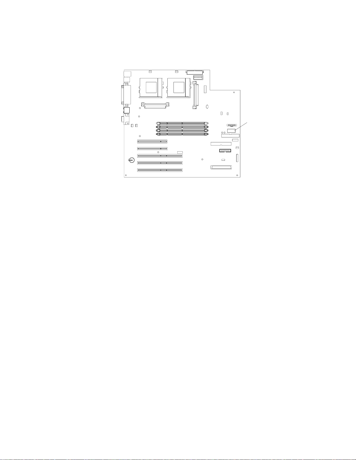
System board
System-board option connectors
The illustrations in the following sections show the components on the system board.
The following illustration identifies system-board connectors for user-installable
options.
Microprocessor 2
(U11)
Microprocessor 1
(U12)
Voltage regulator
module
(VRM) 2 (J12)
DIMM 1
(J19)
DIMM 2
(J21)
DIMM 3
(J23)
DIMM 4
(J26)
PCI 1
(J29)
PCI 2
(J31)
Battery
(BH1)
PCI 5 (J40)
PCI 4 (J39)
PCI 3 (J35)
Voltage regulator
module
(VRM) 1 (J42)
System
management
(J32)
Notes:
1. If your server and operating system support system-management functions and ,
if the optional system-management adapter is installed in your server , the systemmanagement connector (J32) is dedicated for use by the system-management
adapter.
2. The system-management adapter is also known as the service processor.
28 IBM® xSeries 220 User’s Reference
Page 39
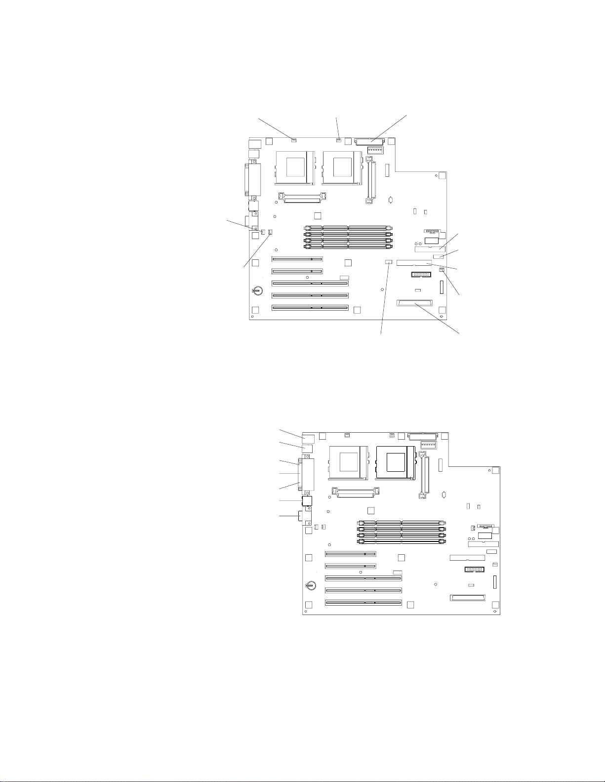
System-board internal cable connectors
The following illustration id entifies system-board connectors for internal cables.
Microprocessor
fan 2 (J2)
Fan 2
power
(J18)
Fan 1
power (J10)
Microprocessor
fan 1 (J3)
Main power
(J1)
Diskette
drive (J27)
2
DASD I C
(J43)
IDE (J30)
Fan 3 power
(J22) (not used)
Wake on LAN
(J20)
System-board external port connectors
The following illustration identi fi es the external port connectors on the rear of the
server.
Keyboard/mouse
USB
Serial A
Parallel
Serial B
Ethernet
Video
SCSI channel
(J41)
Note: For information on adding external SCSI devices to your server, see “SCSI
cabling requirements” on page 67.
Chapter 5. Installing options 29
Page 40

System-board jumpers and switches
The following illustration id entifies the jumpers and switches on the system board.
Switch block
Flash ROM
page-swap
jumper (J38)
System-board jumper blocks
Any jumper blocks on the system board that are not shown in the illustration are
reserved. For normal operation of the system, no jumpers should be installed on any
of the jumper blocks. See “Recovering the BIOS code” on page 97 for information
about the flash ROM page-swap jumper.
System-board switch block
The switch block contains microswitches 1 through 8. As pictured in this illus tration,
switch 8 is at the right of the switch block, an d switch 1 is at the left.
The following table describes the function for each switch. The default setting is Off
for all switches in the switch block.
Switch
number
8 Power-on password-override switch.
7 Reserved.
6 Reserved.
5 Force power on.
4 Reserved.
3 Reserved.
2 Reserved.
1 Reserved.
Switch
description
When toggled to the side that is opposite the default position, bypasses
the power-on password, if one is set.
Table 3. Switches 1 through 8
30 IBM® xSeries 220 User’s Reference
Page 41

Before you begin
Before you begin to install options in your se rver, read the following information:
• Become familiar with the safety and handling guidelines under “Handling
• Make sure that you have an adequate number of properly grounded electrical
• Back up all important data before you make changes to disk drives.
• Have a small, flat-blade screwdriver available.
• For a list of supported options for your server, refer to
System reliability considerations
To help ensure proper cooling and system reliability, make sure that:
• Each of the drive bays has either a drive or a filler panel installed.
• The cover is in place during normal operation, or is removed for no longer than
• There is space around the server to allow the server cooling system to work
• Cables for optional adapters are routed according to the instructions that are
• A failed fan is replaced within one hour.
static-sensitive devices”, and read the safety statements in “Safety information”
on page 32. These guidelines will help you work safely while working with your
server or options.
outlets for your server, monitor, a nd any other options that you intend to install.
http://www.ibm.com/pc/compat on the World Wide Web.
30 minutes while the server is operating.
properly. Leave about 127 mm (5 in.) of space around the front and rear of the
server.
provided with the adapters.
Handling static-sensitive devices
Attention: Static electricity can damage electronic devices and your system. To avoid
damage, keep static-sensitive devices in their static-protective bag until you are ready
to install them.
To reduce the possibility of electrostatic discharge, observe the following precautions:
• Limit your movement. Movement can cause static electricity to build up around
you.
• Handle the device carefully, holding it by its edges or its frame.
• Do not touch solder joints, pins, or exposed printed circuitry.
• Do not leave the device where others can handle and possibly damage the
device.
• While the device is still in its anti-static package, touch it to an unpainted metal
part of the system unit for at least two seconds. (This drains static electricity
from the package and from your body.)
• Remove the device from its package and install it directly into your system unit
without setting it down. If it is necessary to set the device dow n, plac e it on its
static-protective package. (If your device is an adapter, place it component side
up.) Do not place the device on your system unit cover or on a metal table.
• Take additional care when handling devices during cold weather, as h eating
reduces indoor humidity and increases static electricity.
Chapter 5. Installing options 31
Page 42

Safety information
Before installing this product, read the Safety Information book .
Antes de instalar este produto, leia o Manual de Informações sobre Segurança.
Pred instalací tohoto produktu si prectete prírucku bezpecnostních instrukcí.
Læs hæftet med sikkerhedsforskrifter, før du installerer dette produkt.
Lue Safety Information -kirjanen, ennen kuin asennat tämän tuotteen.
Avant de procéder à l'installation de ce produit, lisez le manuel Safety Information.
Vor Beginn der Installation die Broschüre mit Sicherheitshinweisen lesen.
Przed zainstalowaniem tego produktu należy przeczytać broszurę Informacje Dotyczące
Bezpieczeństwa.
Prima di installare questo prodotto, leggere l'opuscolo contenente le informazioni
sulla sicurezza.
Lees voordat u dit product installeert eerst het boekje met veiligheidsvoorschriften.
32 IBM® xSeries 220 User’s Reference
Page 43

Les heftet om sikkerhetsinformasjon (Safety Information) før du installerer dette
produktet.
Antes de instalar este produto, leia o folheto Informações sobr e Segurança.
Перед установкой продукта прочтите брошюру по технике безопасности
(Safety Information).
Pred inštaláciou tohto produktu si pre ítajte Informa nú brožúrku o bezpe nosti.
Preden namestite ta izdelek, preberite knjižico Varnostne informacije.
Antes de instalar este producto, lea la Información de Seguridad.
Läs säkerhetsinformationen innan du installerar den här produkten.
Installálás el tt olvassa el a Biztonsági el írások kézikönyvét !
Chapter 5. Installing options 33
Page 44

Statement 1
Danger
Electrical current from power, telephone, and communication cables is
hazardous.
To avoid a shock hazard:
• Do not connect or disconnect any cables or perform installation,
maintenance, or reconfiguration of this product during an electrical storm.
• Connect all power cords to a properly wired and grounded electrical outlet.
• Connect to properly wired outlets any equipment that will be attached to
this product.
• When possible, use one hand only to connect or disconnect signal cables.
• Never turn on any equipment when there is evidence of fire, water, or
structural damage.
• Disconnect the attached power cords, telecommunications systems,
networks, and modems before you open the device covers, unless instructed
otherwise in the installation and configuration procedures.
• Connect and disconnect cables as described in the following table when
installing, moving, or opening covers on this product or attached devices.
To connect:
1. Turn everything OFF.
2. First, attach all cables to devices.
3. Attach signal cables to connectors.
4. Attach power cords to outlets.
5. Turn device ON.
To disconnect:
1. Turn everything OFF.
2. First, remove power cords from
outlets.
3. Remove signal cables from
connectors.
4. Remove all cables from devices.
34 IBM® xSeries 220 User’s Reference
Page 45

Statement 2
CAUTION:
When replacing the lithium battery, use only IBM Part Number 33F8354 or an
equivalent type battery recommended by the manufacturer. If your system has a
module containing a lithium battery, replace it only with the same module type
made by the same manufacturer. The battery contains lithium and can explode if
not properly used, handled, or disposed of.
Do not:
• Throw or immerse into water.
• Heat to more than 100 C (212 F)
• Repair or disassemble
Dispose of the battery as required by local ordinances or regulations.
Statement 3
CAUTION:
When laser products (such as CD-ROMs, DVD drives, fiber optic devices, or
transmitters) are installed, note the following:
• Do not remove the covers. Removing the covers of the laser product could
result in exposure to hazardous laser radiation. There are no serviceable
parts inside the device.
• Use of controls or adjustments or performance of procedures other than
those specified herein might result in hazardous radiation exposure.
Danger
Some laser products contain an embedded Class 3A or Class 3B laser diode. Note
the following. Laser radiation when open. Do not stare into the beam, do not view
directly with optical instruments, and avoid direct exposure to the beam.
Chapter 5. Installing options 35
Page 46

Statement 4
≥18 kg (39.7 lbs)
CAUTION:
Use safe practices when lifting.
Statement 5
CAUTION:
The power control button on the device and the power switch on the power
supply do not turn off the electrical current supplied to the device. The device
also might have more than one power cord. To remove all electrical current from
the device, ensure that all power cords are disconnected from the power source.
≥32 kg (70.5 lbs)
≥55 kg (121.2 lbs)
2
1
36 IBM® xSeries 220 User’s Reference
Page 47

Rotating the stabilizing feet
The feet attached to the bottom cover rotate 90 degrees to provide additional stability
for your server.
Place the server in an upright position; then, rotate the feet a quarter turn away from
the server. Carefully position the server on its feet.
When you need to access the inside of the server to install options, you might find it
easier to place the server on its side, so that the system board is facing you. If you do
so, rotate the feet in towards the server, so that they do not break off due to the weight
of the server.
Chapter 5. Installing options 37
Page 48

Removing the side cover
The following information describes h ow to remove the side cover.
Note: The illustrations in this document might differ slightly from your hardware.
Cover-release
latch
Key lock
To remove the side cover from the server, do the following:
1. Review the information in “Before you begin” on page 31.
2. T urn of f the server and all attached devices, and disconnect all external cables and
power cords.
3. If necessary, unlock the server cover.
4. Pull out on the cover-release latch at the rear of the server; then, slide the cover
toward the rear of the server and remove it.
Attention: For proper cooling and airflow , replace the cover before turning on the
server. Operating the server for extended periods of time (over 30 minutes) with
the cover removed might damage server components.
5. For a tower model, rotate the stabilizing feet on the bottom of the server, and
place the server on its side to install or remove components.
38 IBM® xSeries 220 User’s Reference
Page 49

Removing the support bracket assembly
When working with some options such as hard disk drives and microprocessors, you
must first remove the support bracket assembly to access the location of the o p tion.
The support bracket assembly consists of a support bracket, an air baffle, and a fan.
To remove the support bracket assembly, do the following:
1. Review the safety precautions in “Safety information” on page 32.
2. Turn off the server and peripheral devices and disconnect all external cables and
power cords.
3. Remove the side cover (see “Removing the side cover” on page 38 for details).
4. If your server is a non-hot-swap model, continue with step 6.
5. If your server is a hot-swap model, press down on the latches on either side of
connector J42, and remove the voltage regulator module (VRM) from connector
J42. (See “System-board option connectors” on page 28 for connector locations.)
Note: Remember to reinstall this VRM after you reinstall the support bracket
assembly.
6. Disconnect the fan cable (connector J10) from the system board. (See “System-
board internal cable connectors” on page 29 for connector locations.)
Note: Remember to reconnect this cable after you reinstall the support bracket
assembly.
7. Carefully pull up on the end of the support bracket assembly that is closer to the
rear of the server; then, rotate and lift the support bracket assembly out of the
server.
Chapter 5. Installing options 39
Page 50

8. Store the support bracket assembly in a safe place.
Working with adapters
Y ou can install up to five peripheral component interconnect (PCI) adapters in the PCI
slots on the system board of your server. See the xSeries 220 ServerProven list at
http://www.ibm.com/pc/compat/ for a list of PCI adapters that your server
supports.
Y our server comes with an integrated video controller on the system board. When you
install a video adapter, the server BIOS code automatically disables the integrated
video controller.
Note: The illustrations in this document might differ slightly from your hardware.
The following illustration shows the location of the 33 MHz PCI slots on the system
board.
PCI slot 1 32-bit
33 MHz (J29)
PCI slot 2 32-bit
33 MHz (J31)
PCI slot 3 64-bit
33 MHz (J35)
PCI slot 4 64-bit
33 MHz (J39)
PCI slot 5 64-bit
33 MHz (J40)
Adapter considerations
Before you install adapters, review the following:
• Locate the documentation that comes with the adap ter, and follow those
instructions in addition to the instructio ns given in this chapter. If you need to
change switch or jumper settings on your adapter, follow the instructions that
come with the adapter.
• You can install full-length adapters in all PCI slots.
• You can install a 32-bit adapter in any of th e P C I slots, but you might want to
install it in a 32-bit slot and use the 6 4-b it slots for 64-bit adapters.
• Your server supports 5.0V and universal PCI adapters; it does not support 3.3V
adapters.
• Your server uses a rotational interrupt technique to configure PCI adapters.
Because of this technique, you can install a variety of PCI adapters that currently
do not support sharing of PCI interrupts.
• The server has two PCI buses. PCI slots 1 and 2 are on PCI bus A, and PCI slots
3, 4, and 5 are on PCI bus B.
Note: PCI bus A is sometimes referred to as bus 0; PCI bus B is sometimes
referred to as bus 1.
40 IBM® xSeries 220 User’s Reference
Page 51

The system scans PCI slots 1 through 5 to assign system resources; then, the
system starts (boots) the PCI de vice s in the following order: PCI slots 1 and 2,
system board SCSI devices, and then PCI slots 3 through 5.
• If you plan to use the Wake on LAN (WOL) function in the server, you must
install a Wake on LAN-enabled NIC adapter in PCI slot 1, and install the Wake
on LAN cable that comes with the W ake on LAN adapter to connect this adapter
to the system board. You must use a Wake on LAN-enabled ada pter as identified
in the xSeries 220 ServerProven list at http://www .ibm.com/pc/compat/. Only
PCI slot 1 supports a Wake on LAN-enabled adapter. For additional information
on the Wake on LAN function, adapter, and cables, refer to the documentation
that comes with the Wake on LAN adapter.
• If you plan to use the optional system-management adap ter in the server, you
must install the optional system-management adapter in PCI slot 2. Only PCI
slot 2 supports the optional system-management adapter. Fo r additional
information on the optional system- management adapter, refer to the
documentation that comes with the a dapter.
Installing an adapter
Expansion-slot
cover
Rear adapter
retaining
bracket
Adapter
Front adapter
support
bracket
Attention: When you handle electrostatic discharge (ESD) sensitive devices, take
precautions to avoid damage from static electricity. For details on handling these
devices, see “Handling static-sensitive devices” on page 31.
To install an adapter, do the following:
1. Review the safety precautions in Statement 1 and Statement 5 in “Safety
information” on page 32.
2. Turn off the server and peripheral devices, and disconnect all external cables and
power cords; then, remove the side cover. See “Removing the side cover” on page
38 for details.
Chapter 5. Installing options 41
Page 52

3. Carefully remove the support bracket assembly from the server (see “Removing
the support bracket assembly” on page 39). Store the cover and the support
bracket assembly in a safe place.
4. Determine which PCI slot you will use for the adapter.
Note: Check the instructions that come with the adapter for any requirements
or restrictions.
5. Remove the rear adapter retaining bracket from the server. If you are installing a
full-length adapter, rotate the front adapter support bracket to the open
(unlocked) position.
6. Remove the expansion-slot cover. Store it in a safe place for future use.
Attention: Expansion-slot covers must be installed on all vacant slots. This
maintains the electronic emission characteristics of the system and ensures proper
cooling of system components.
7. Refer to the documentation that comes w ith your adapter for any cabling
instructions. It might be easier for you to route cables before you install the
adapter.
8. Remove the adapter from the static-protective package.
Attention: Avoid touching the components and gold-edge connectors on the
adapter.
9. Place the adapter, component-side up, on a flat, static-protective surface.
10. Set any jumpers or switches as described by the adapter manufacturer.
11. Install the adapter:
a. Carefully grasp the adapter by its top edge or upper corners, and align it with
the expansion slot on the system board.
b. Press the adapter firmly into the expansion slot.
Attention: When you install an adapter in the server, be sure that it is
completely and correctly seated in the system-board connector before you
apply power. Incomplete insertion might cause damage to the system board
or the adapter.
c. When the adapter is fully seated, release the front adapter support bracket by
pushing inward on the latch. Make sure that the front adapter support
bracket holds the adapter securely in place.
d. If you opened the front adapter support bracket, rotate it to the closed
(locked) position; then, reinstall the rear adapter retaining bracket in the
server.
42 IBM® xSeries 220 User’s Reference
Page 53

12. Connect any needed cables to the adapter.
Attention: Route cables so that they do not block the flow of air from the fans.
The following illustration shows how to reroute the SCSI cable. If you install a
ServeRAID adapter and intend to use it with hot-swap hard disk drives, remove
the cable from the internal SCSI connector (J41) on the system board and connect
it to the ServeRAID adapter.
Note: You can also install a ServeRAID adap ter in non-hot-swap models;
however, non-hot-swap models do not support hot-swap hard disk
drives.
SCSI cable
ServeRAID
adapter
SCSI connector
(J41)
13. If you have other options to install or remove, do so now; otherwise, replace the
support bracket assembly; then, go to “Installing the side cover” on page 60.
Note: If your server is a hot-swap model, reinstall the VRM in connector J42
after you reinstall the support bracket assembly. (See “System-board
option connector s” on page 28 for connector location.)
Chapter 5. Installing options 43
Page 54

Installing internal drives
Different types of drives enable your system to read multiple types of media and store
more data. Several types of drives are available, such as:
• Diskette (preinstalled)
• Hard disk (preinstalled on some models)
• CD-ROM (preinstalled)
• Tape
Internal drive bays
Interna l d riv es are installed in bays. The bays of the xSeries 220 are in the front of the
server, as shown in the following illustration.
Note: The illustrations in this document might differ slightly from your hardware.
Bay 1
Bay 2
Bay 3
Bay4
Bay 5
Bay 6
Bay 7
To remove or install a drive, you must turn off the server first, unless you are
removing or installing a hot-swap hard disk drive. Diskette drives, tape drives, and
CD-ROM drives are removable-media drives. You can install r emovable-media drives
in bays 1, 2, 3, and 4. You can install SCSI hard disk drives in bays 4, 5, 6, and 7.
• Your server comes with a 3.5-inch, 1.44 MB diskette drive in bay 3, an integrated
drive electronics (IDE) CD-ROM drive in bay 1, and a hard disk drive in bay 7
(in some models).
• The xSeries 220 server supports five 3.5-inch drives; however, the server
supports only one diskette drive.
• The diskette drive uses 1 MB and 2 MB diskettes. For optimum use, format 1 MB
diskettes to 720 KB and format 2 MB diskettes to 1.44 MB.
• The xSeries 220 server supports two 5.25-inch drives and four SCSI hard disk
drives. The server does not support IDE hard disk dri ves. Some models su pport
hot-swap hard disk drives. Other models support only non-hot-swap hard disk
44 IBM® xSeries 220 User’s Reference
Page 55

drives. Refer to the documentation that comes with your server for additional
information.
Your server supports four 1-inch (26 mm) slim, 3.5-inch SCSI hard disk drives in
the hard disk drive bays (4, 5, 6, and 7). You can install four non-hot-swap hard
disk drives in the models that have the standard non-hot-swap drive cage. You
can install three hot-swap hard disk drives and one non-hot-swap hard disk
drive in the models that come with the hot-swap drive cage. Both the non-hotswap and hot-swap drive cages hold a maximum of three hard disk drives. The
drive cages comprise bays 5, 6, and 7.
• Bay 2 comes without a device installed. This bay is for a 5.25-inch, half-high,
removable-media drive, such as a tape backup drive.
• Bay 4 is for a 3.5-inch, slim, removable-media drive or SCSI hard disk drive.
Note: The electromagnetic interference (EMI) integrity and cooling of the server ar e
both protected by having bays 1 through 4 covered or occupied. When you
install a drive, save the filler panel from the bay, in case you later remove the
drive and do not replace it with another.
Preinstallation steps (all bays)
Before you install drives in your server, verify that you have all the cables and any
other equipment specified in the documentation that comes with the drive. You might
also need to perform certain preinstallation activities. Some of the steps are required
only during the initial ins ta llation of an opt ion.
1. Read “Safety” on page v, “Handling static-sensitive devices” on page 31, and the
documentation that comes with your drive.
2. Choose the bay in which you want to install the drive.
3. Check the instructions that come with the drive to see if you need to set any
switches or jumpers on the drive.
Chapter 5. Installing options 45
Page 56

Installing a drive in bay 1, 2, 3, or 4
EMC shield
Filler panel
To install a drive in bay 1, 2, 3, or 4, do the followin g:
1. Read the information in “Preinstallation steps (all bays)” on page 45.
2. Turn off the server and peripheral devices; then, remove the side cover (see
“Removing the side cover” on page 38 for details).
3. Insert a screwdriver into the slot on the right side of the filler panel, and remove
the filler panel from the server.
4. Insert a screwdriver into the slots on the front of the electromagnetic
compatibility (EMC) shield, and remove the EMC shield from the bay.
46 IBM® xSeries 220 User’s Reference
Page 57

5. If the drive is a laser product, observe the following safety precaution.
Statement 3
CAUTION:
When laser products (such as CD-ROMs, DVD drives, fiber optic devices, or
transmitters) are installed, note the following:
• Do not remove the covers. Removing the covers of the laser product could
result in exposure to hazardous laser radiation. There are no serviceable
parts inside the device.
• Use of controls or adjustments or performance of procedures other than
those specified herein might result in hazardous radiation exposure.
Danger
Some laser products contain an embedded Class 3A or Class 3B laser diode. Note
the following. Laser radiation when open. Do not stare into the beam, do not view
directly with optical instruments, and avoid direct exposure to the beam.
6. Touch the static-protective bag containing the drive to any unpainted metal
surface on the server; then, remove the drive from the bag and place it on a staticprotective surface.
7. Set any jumpers or switches on the drive according to the documentation that
comes with the drive.
8. Push the drive into the bay.
9. If the drive is an IDE device, plug one connector of the IDE cable into the back of
the drive and the other end of the cable into the IDE connector (J30) on the system
board.
If the drive is a SCSI device, plug one connector of the SCSI cable into the back of
the drive and make sure that the other end of the cable is connected to the SCSI
connector (J41) on the system board.
Note: Ensure that you route the SCSI cable so that it does not block the airflow
to the rear of the drives or over the microprocessors.
10. Connect a power cable to the back of the drive. The connectors are keyed and can
be inserted only one way.
11. If you are installing another drive, do so now. Otherwise, continue with the next
step.
12. If you have other options to install or remove, do so now; otherwise, replace the
cover (see “Installing the side cover” on page 60 for details) .
Chapter 5. Installing options 47
Page 58
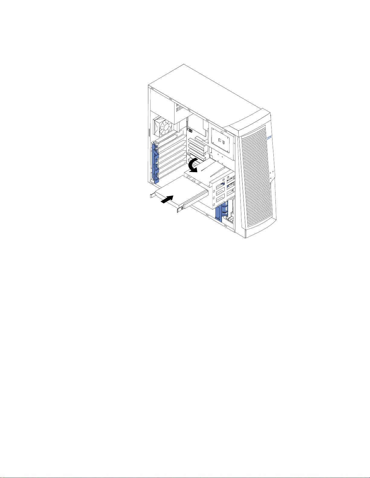
Installing a non-hot-swap hard disk drive in bay 5, 6, or
7
To install a non-hot-swap hard disk drive in bay 5, 6, or 7, do the following:
1. Read the information in “Preinstallation steps (all bays)” on page 45.
2. Turn off the server and peripheral devices, and disconnect all external cables and
power cords; then, remove the side cover (see “Removing the side cover” on page
38 for details).
3. Remove the support bracket assembly (see “Removing the support bracket
assembly” on page 39).
4. Rotate the drive cage upward. If your server has a hard disk drive installed in the
drive cage, disconnect the cables from the rear of the drive.
5. Remove the plastic bag that contains the drive rails and screws from inside the
drive cage.
6. Install rails on each drive:
a. Pull the blue slide rails out of the plastic bag.
b. Install the screws on the sides of the drive.
c. Align the rails on the drive with the guide rails in the drive bay.
d. Push the drive into the bay until it clicks into place.
7. Reinstall the drive cage in the server. Rotate the drive cage downward until it
snaps into place.
8. Connect the SCSI and power cables to the rear of the drives.
Note: Ensure that you route the SCSI cable so that it does not block the airflow
to the rear of the drives or over the microprocessors.
48 IBM® xSeries 220 User’s Reference
Page 59
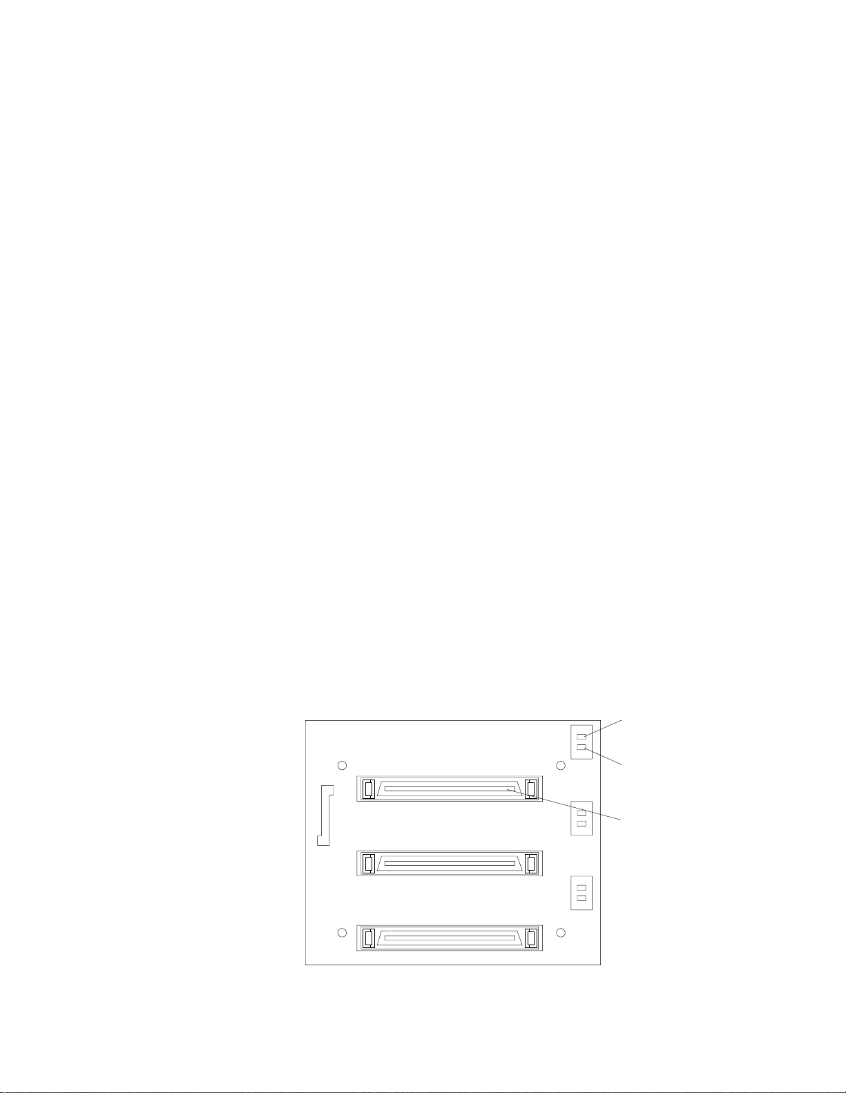
9. If you have other options to install or remove, do so now; otherwise, replace the
support bracket assembly; then, go to “Installing the side cover” on page 60.
Note: If your server is a hot-swap model, reinstall the VRM in connector J42
after you reinstall the support bracket assembly. (See “System-board
option connector s” on page 28 for connector location.)
Installing a hot-swap hard disk drive in bay 5, 6, or 7
If you purchased a hot-swap model, your server contains hardware that you can use
to replace a failed hard disk drive without turning off the server. Therefore, you have
the advantage of continuing to operate your system while a hard disk drive is
removed or installed. These drives are known as hot-swap drives. If these drives are
connected to an optional controller , such as a ServeRAID controller, that supports this
function, and if one of these drives becomes defective, the ServeRAID controller can
rebuild the data from that drive onto another hot-swap drive. Refer to the information
that comes with your ServeRAID controller for details.
Each hot-swap drive has two indicator lights: the hard disk drive activity light and the
hard disk drive status light. When the green hard disk drive activity light is flashing,
the controller is accessing the hard disk drive. When this occurs, the SCSI activity light
on the front of the server also illuminates. The SCSI activity light is illustrated and
described in “Server controls and indicators” on page 5. If the amber hard disk drive
status light for a drive is lit continuously, that individual drive is faulty a nd requires
replacement. When the hard disk drive status light indicates a drive fault, you can
replace a hot-swap drive without turning off the server.
Note: The hard disk drive activity light is also known as the SCSI hard disk drive
activity light.
Each hot-swap drive that you plan to install must be mounted in a hot-swa p - d rive
tray. The drive must have a single connector attachment (SCA) connector. Hot-swapdrive trays come with hot-swap drives.
The hot-swap bays connect to a SCSI backplane. This backplane is the printed circuit
board behind the bay. The backplane controls the SCSI IDs for the hot-swap drives.
The following illustration shows the hot-swap-drive backplane component locations,
as viewed from the front of the server.
Note: The illustrations in this document might differ slightly from your hardware.
Hard disk
drive activity
light (green)
Hard disk
drive status
light (amber)
SCSI hot-swap
hard disk drive
connector
Chapter 5. Installing options 49
Page 60

Note: The hard disk drive activity light and hard disk drive status light on the
backplane match the hard disk drive activity light and hard disk drive status
light on the hot-swap drive.
The following illustration shows the rear connectors on the hot-swap-drive
backplane, as viewed from the rear of the server.
SCSI cable
connector
SCSI power
cable connector
2
I C cable
connector
The following illustration shows how to install a hot-swap hard disk drive in the
server. When you install hot-swap hard disk drives, install them in the following
order: bay 7, bay 6, and bay 5.
Filler panel
Drive tray
assembly
Drive tray handle
(in open position)
Attention:
• When you handle electrostatic discharge (ESD) sensitive devices, take
precautions to avoid damage from static electricity. For details on handling these
devices, see “Handling static-sensitive devices” on page 31.
• To maintain proper system cooling, do not operate the server for more than 10
minutes without either a drive or a filler panel installed in each bay.
To install a hot-swap hard disk drive in bay 5, 6, or 7, do the foll owing:
1. Review “Before you begin” on page 31.
2. Read the information in “Preinstallation steps (all bays)” on page 45.
50 IBM® xSeries 220 User’s Reference
Page 61

Note: You do not have to turn off the server to install hot-swap hard disk drives
in these bays.
3. Remove the filler panel from one of the empty hot-swap bays by inserting your
finger into the depression at the left side of the filler panel a nd pulling it away
from the server.
4. Install the hard disk drive in the hot-swap bay:
a. Ensure that the tray handle is open (that is, perpendicular to the drive).
b. Align the drive tray assembly with the guid e rails in the bay.
c. Gently push the drive tray assembly into the bay until the drive stops.
d. Push the tray handle to the closed (locked) position.
e. Check the hard disk drive status light to verify that the hard disk drive is
operating properly.
If the amber hard disk drive status light for a drive is lit continuously, that
individual drive is faulty and needs to be replaced. If the green hard disk
drive activity light is flashing, the drive is being accessed.
Note: If your server has a ServeRAID controller, you might need to reconfigure
your disk arrays after installing hard disk drives. Refer to the information
that comes with your ServeRAID controller.
5. If you have other options to install or remove, do so now.
Installing memory modules
Adding memory to your server is an easy way to make programs run faster. You can
increase the amount of memory in your server by installing options called memory-
module kits. Each kit contains one industry-standard, dual in-line memory module
(DIMM). Your server uses a noninterleaved memory configuration.
Your server comes with a DIMM that is installed on the system board in DIMM
connector 1 (labeled DIMM 1).
Notes:
1. When installing additional memory modules, install the second memory module
in the connector labeled DIMM 2, the third in connector DIMM 3, and the fourth
in connector DIMM 4. (See the following illustration for memory-connector
locations.)
2. Your xSeries 220 server supports 128 MB, 256 MB, 512 MB, and 1 GB DIMMs.
These DIMMs can be installed in any memory slot. Your server supports a
minimum of 128 MB and a maximum of 4GB of system memory. See the
ServerProven list at http://www.ibm.com/pc/compat/ for a list of memory
modules for use with your server.
3. Installing or removing DIMMs cha nges the configuration information in the
server. Therefore, after installing or removing a DIMM, you must save the new
configuration information by using the Configuration/Setup Utility program.
When you restart the server, the system displays a message indicating that the
memory configuration has changed. Start the Configuration/Setup Utility
program and select Save Settings. See “Chapter 3. Configuring your server,” on
page 11 for more information.
4. The illustrations in this document might differ slightly from your hardware.
Chapter 5. Installing options 51
Page 62
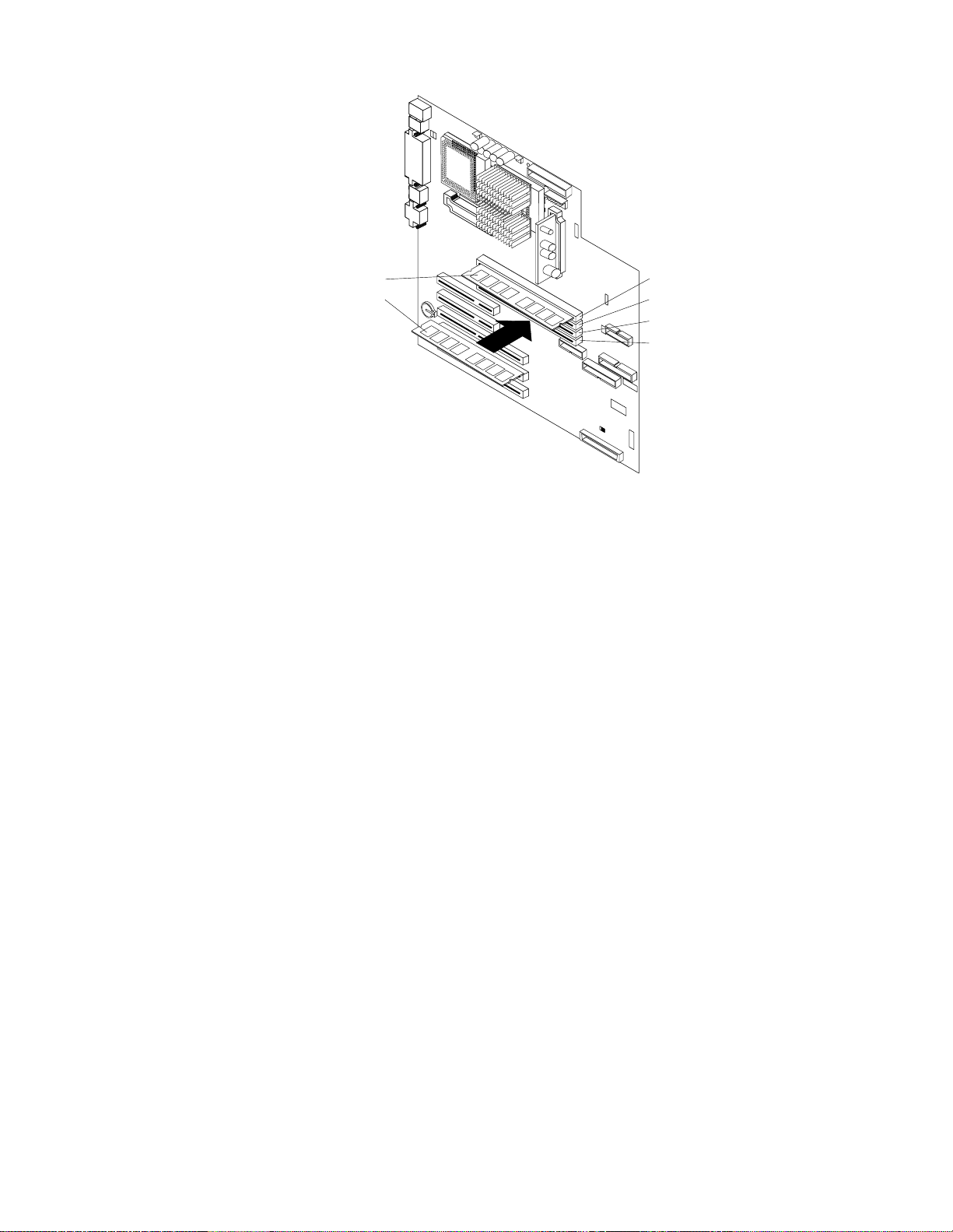
DIMM connector 1DIMM 1
DIMM connector 2DIMM 2
DIMM connector 3
DIMM connector 4
Attention: When you handle electrostatic discharge (ESD) sensitive devices, take
precautions to avoid damage from static electricity. For details on handling these
devices, see “Handling static-sensitive devices” on page 31.
To install a DIMM, do the following:
1. Review the safety precautions in Statement 1 and Statement 5 in “Safety
information” on page 32.
2. Review the information in “Before you begin” on page 31 and the documentation
that comes with your option.
3. Turn off the server and peripheral devices, and disconnect all external cables and
power cords; then, remove the side cover (see “Removing the side cover” on page
38 for details) .
4. Select the connector in which to install th e DIM M.
5. Touch the static-protective package containing the DIMM to any unpainted metal
surface on the server. Then, remove the DIMM from the package.
Attention: To avoid breaking the retaining clips or damaging the DIMM
connectors, handle the clips gently.
6. Install the DIMM:
a. Open the retaining clips on the connector.
b. Turn the DIMM so that the pins align correctly with the connector.
c. Firmly press the DIMM straight down into the connector by applying
pressure on both ends of the DIMM simultaneously.
d. Make sure that the retaining clips are in the closed position. If a gap exists
between the DIMM and the retaining clips, the DIMM has not been properly
installed. In this case, open the retaining clips and remove the DIMM; then,
reinsert the DIM M.
7. If you have other options to install or remove, do so now; otherwise, go to
“Installing the side cover” on page 60.
Attention: When you restart the server, the system displays a message indicating that
the memory configur ation has changed.
52 IBM® xSeries 220 User’s Reference
Page 63

• If you installed additional memory, start the Configuration /Setup Utility
program and select Save Settings.
• If you just replaced a failed DIMM, you must start the Configuration /Setup
Utility program, select Advanced Setup, select Memory Settings, highlight the
connector or bank of connectors that you want to enable, then select Enable.
• In some memory configurations, the 3-3-3 beep code might sound during POST
followed by a blank screen. If this occurs, you must restart the server three times
to force the system BIOS code to reset the memory connector or bank of
connectors from Disabled to Enabled.
Chapter 5. Installing options 53
Page 64

Installing and removing a microprocessor
Your server comes with one microprocessor, which is installed on the system board. If
you install an additional microprocessor kit, your server can operate as a symmetric
multiprocessing (SMP) server. With SMP, certain operating systems a nd application
programs can distribute the processing load between the microprocessors. This
enhances performance for database and point-of-sale applications, integrated
manufacturing solutions, and other applications.
Notes:
1. Before you install a new microprocessor, review the documentation that come s
with the microprocessor, so that you can determine whether you need to update
the server basic input/output system (BIOS) code. The latest level of BIOS code
for your server is available through the World Wide Web. Refer to “Getting help,
service, and information” on page 115 for the appropriate World Wide Web
addresses.
2. Obtain an SMP-capable operating system (optional). For a list of supported
operating systems, see http://www.ibm.com/pc/compat/ on the World Wide
Web.
3. Your server comes with one microprocessor, which is installed in microprocessor
connector U12 (the microprocessor connector that is closer to the power supply).
This is the startup (boot) microprocessor. If you install a microprocessor in
microprocessor connector U11, that one becomes the startup microprocessor, and
the microprocessor that is installed in microprocessor connector U12 is the
application microprocessor. You must also install a VRM when you install a
microprocessor.
4. If you are installing a microprocessor that has a speed of 933 MHz or higher, you
must also install a fan sink and connect the fan-sink power cable to the system
board.
5. The illustrations in this document might differ slightly from your server.
6. If necessary , see “System-board option connectors” on page 28 for connector
locations.
Attention:
• To avoid damage and ensure proper server operation when you install a new or
additional microprocessor, use microprocessors that have the sa me cache size
and type and the same clock speed. Microprocessor internal clock frequencies
and external clock frequencies must be identical. See the ServerProven list at
http://www.ibm.com/pc/compat for a list of microprocessors for use with
your server.
• When you handle electrostatic discharge (ESD) sensitive devices, take
precautions to avoid damage from static electricity. For details on handling these
devices, see “Handling static-sensitive devices” on page 31.
Installing a microprocessor
To install an additional microprocessor, do the following:
1. Review the safety precautions in Statement 1 and Statement 5 in “Safety
information” on page 32.
2. Turn off the server and peripheral devices, and disconnect all external cables and
power cords; then, remove the side cover (see “Removing the side cover” on page
38 for details).
3. Carefully remove the support bracket assembly from the server (see “Removing
the support bracket assembly” on page 39). Store the cover and the support
54 IBM® xSeries 220 User’s Reference
Page 65

bracket assembly in a safe place.
4. Lift the release lever and remove the terminator card from the microprocessor
connector.
5. Install the microprocessor:
a. T ouch the static-pr otective package containing the new micropro cessor to any
unpainted metal surface on the server; then, remove the microprocessor from
the package.
b. Orient the microprocessor over the microprocessor connector, as shown in the
following illustration. Carefully press the microprocessor into the connector.
Microprocessor 2
connector
Terminator card
Microprocessor 2
Microprocessor
orientation indicator
Lever
Attention: To avoid bending the pins, do not use excessive force when pressing
the microprocessor into the connector.
6. Push the release lever down to lock the microprocessor into place.
7. If you are installing a microprocessor that has a speed of 933 MHz or higher,
continue with step 9 on page 57.
If you are installing a microprocessor that has a speed lower than 933 MHz,
continue with step 8 on page 56.
Chapter 5. Installing options 55
Page 66
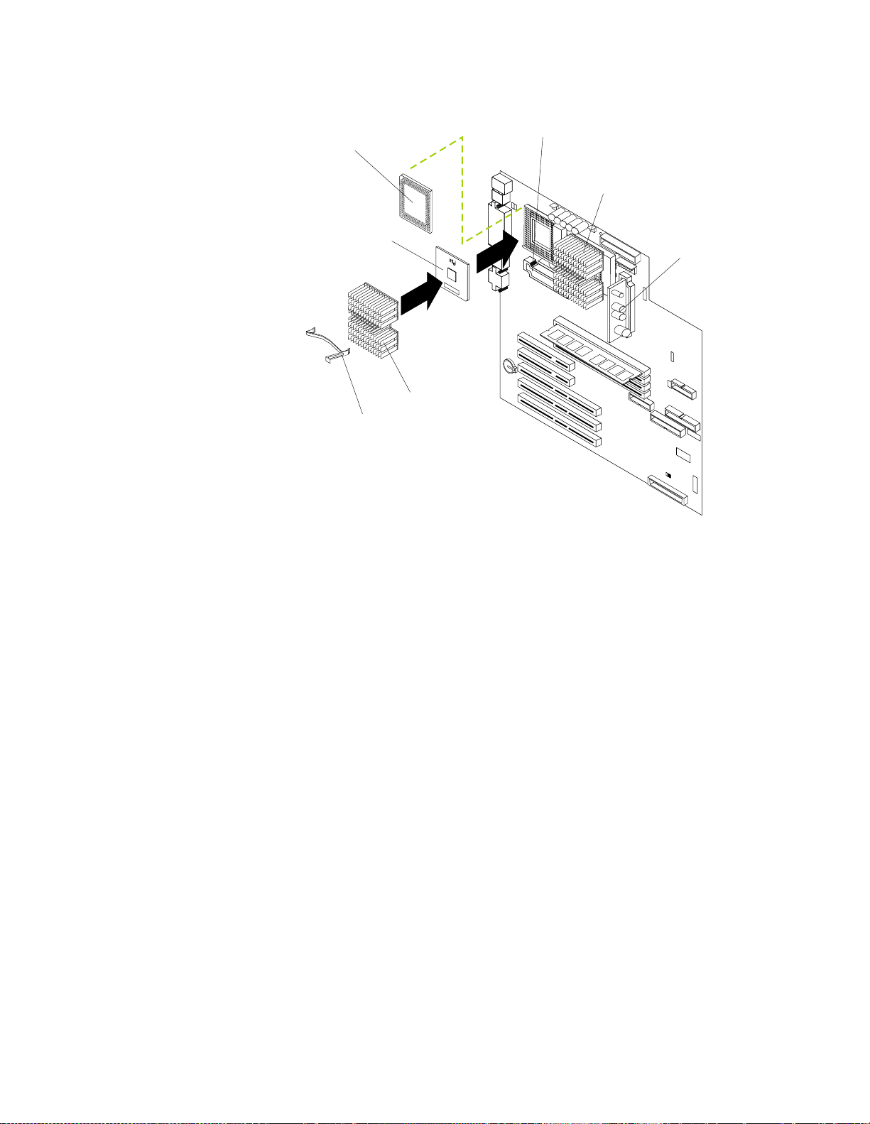
8. If you are installing a microprocessor that has a speed lower than 933 MHz, install
the heat sink onto the microprocessor:
VRM 2
Terminator card
Microprocessor 2
Heat-sink
retainer
Heat sink
(J12)
Microprocessor 1
VRM 1
(J42)
a. Peel the plastic protective strip off the bottom of the heat sink. Make sure
that the square of thermal material is still on the bottom of the heat sink.
b. Align and place the heat sink on top of th e microprocessor.
c. Align and place the heat-sink retainer (clip) over the heat sink; then, snap it
into place.
d. Continue with step 10 on page 57.
56 IBM® xSeries 220 User’s Reference
Page 67

9. If you are installing a microprocessor that has a speed of 933 MHz or higher,
install a fa n s i nk o nt o t h e mi croprocessor and co nn ec t t he fan-sink powe r cable to
the system board:
VRM 2
Terminator card
(J12)
Microprocessor
fan 1 (J2)
Microprocessor
fan 2 (J3 )
Microprocessor
Fan sink
Fan-sink
retainer
VRM 1
(J42)
a. Peel the plastic protective strip off the bottom of the fan sink. Make sure that
the square of thermal material is still on the bottom of the fan sink.
b. Align and place the fan sink on top of the microprocessor.
c. Align and place the fan-sink retainer (clip) over the fan sink.
d. Insert a small, flat-blade screwdriver into the tab on the fan-sink retainer.
e. Press down and in with the screwdriver handle to snap the fan-sink retainer
into place in the slot on the microprocessor, over the fan sink.
f. Connect the built-in fan-sink power cable to the appropriate connector on the
system board:
• If you installed the microprocessor in connector U11, connect the fansink power cable to connector J2.
• If you installed the microprocessor in connector U12, connect the fansink power cable to connector J3.
10. Place the terminator card in the static-protective package that your new
microprocessor was shipped in, and store it in a safe place. You will need to install
the terminator card again if you ever remove the microprocessor and do not
replace it with another microprocessor.
11. Install the VRM that is included in the microprocessor kit.
Attention: Use of other VRMs might cause your server to overheat.
a. Center the VRM over the appropriate VRM connector:
(1) If you installed the microprocessor in connector U11, press down on the
latches on either side of connector J12, and install the VRM in connector
J12.
Chapter 5. Installing options 57
Page 68

(2) If you installed the microprocessor in connector U12, press down on the
latches on either side of connector J42, and install the VRM in connector
J42.
Note: If your server is a hot-swap model, reinstall the VRM in connector J42
after you reinstall the support bracket assembly.
b. Make sure that the VRM is oriented and aligned correctly.
c. Press the VRM into the connector.
Note: If you remove the microprocessor later, remember to install the
terminator card in the appropriate microprocessor connector and to
remove the VRM from the appropriate VRM connector.
12. If you have other options to install or remove, do so now; otherwise, replace the
support bracket assembly; then, go to “Installing the side cover” on page 60.
Removing a microprocessor
To remove a microprocessor, do the following:
Note: Do not use any tools when removing the microprocessor; however, you will
need a small, flat-blade screwdriver to remove the fan-sink retainer (clip).
Attention: When you handle electrostatic discharge (ESD) sensitive devices, take
precautions to avoid damage from static electricity. For details on handling these
devices, see “Handling static-sensitive devices” on page 31.
1. Review the safety precautions in Statement 1 and Statement 5 in “Safety
information” on page 32.
2. Turn off the server and peripheral devices, and disconnect all external cables and
power cords; then, remove the side cover (see “Removing the side cover” on page
38 for details).
3. Carefully remove the support bracket assembly from the server (see “Removing
the support bracket assembly” on page 39). Store the cover and the support
bracket assembly in a safe place.
4. If your server is a hot-swap model, press down on the latches on either side of
connector J42, and remove the VRM from connector J42. (See “System-board
option connectors” on page 28 for connector location.)
Note: Remember to reinstall this VRM after you reinstall the support bracket
assembly, unless you are not replacing the microprocessor.
5. If you are removing a microprocessor that has a speed lower than 933 MHz:
a. Push down and back on the lever to remove the retainer (clip) from the heat
sink.
b. Firmly grasp the heat sink and lift it off the microprocessor. Stor e the heat sink
in a safe, clean place with the bottom side up. The thermal material on the
heat sink must stay clean if you intend to reuse the heat sink in the future.
c. Continue with step 7 on page 59.
6. If you are removing a microprocessor that has a speed of 933 MHz or higher:
a. Insert a small, flat-blade screwdriver into the tab on the fan-sink retainer
(clip).
b. Press down and in with the screwdriver handle to remove the fan-sink
retainer from the fan sink.
c. Firmly grasp the fan sink and lift it off the microprocessor. Store the fan sink
in a safe, clean place with the bottom side up. The thermal material on the fan
sink must stay clean if you intend to reuse the fan sink in the future.
58 IBM® xSeries 220 User’s Reference
Page 69

d. Disconnect the fan-sink power cable from the appropriate connector on the
system board:
• If you are removing the microprocessor from connector U11, disconnect
the fan-sink power cable from connector J2.
• If you are removing the microprocessor from connector U12, disconnect
the fan-sink power cable from connector J3.
7. Lift up the release lever and remove the micropro cessor fr o m the connector. Store
the microprocessor in a static-protective bag for possible future use.
8. If you are installing a new microprocessor, go to “Installing a microprocessor” on
page 54.
9. If you are not replacing the microprocessor:
a. Reinstall the terminator card in the empty microprocessor connector.
b. Press the release lever down to lock the terminator card into place.
c. Remove the VRM from the appropriate VRM connector:
• If you removed the microprocessor from connector U11, press down on
the latches on either side of connector J12, and remove the VRM from
connector J12.
• If you removed the microprocessor from connector U12, press down on
the latches on either side of connector J42, and remove the VRM from
connector J42.
10. If you have other options to install or remove, do so now; otherwise, replace the
support bracket assembly; then, go to “Installing the side cover” on page 60.
Chapter 5. Installing options 59
Page 70

Installing the side cover
The following information describes the cover installation procedure.
Note: The illustrations in this document might differ slightly from your hardware.
Cover-release
latch
Key lock
Note: If you removed the support bracket assembly after you removed the cover,
reinstall it before you install the cover.
To install the server side cover:
1. Clear any cables that might impede the replacement of the cover.
2. Align the bottom tabs of the side cover with the matching slots in the server
chassis; then, insert the tabs into the slots.
3. Close the cover-release latch to pull the cover forward and lock the cover in place.
4. Make sure that the stabilizing feet are rotated outward so that they properly
support the server.
5. Reconnect the external cables and cords to the server; then, plug the power cords
into electrical outlets.
60 IBM® xSeries 220 User’s Reference
Page 71

Connecting external options
You can attach a SCSI storage expansion enclosure to your server if you install an
optional SCSI adap ter in one of the five PCI adapter slots on the system board.
Installation procedure
To attach an external device, do the following:
1. Read “Bef or e yo u begi n” on page 31 an d the documentation that comes with your
options.
2. Be sure that your server and all attached devices are turned off.
3. Follow the instructions that come with the option to pr epare it f or installation and
to connect it to the server.
Note: If you ar e attaching a SCSI device , see “SCSI port” on page 67 for SCSI ID
and cabling information.
I/O connector locat ions
The following illustration sho ws the external input/output connectors (ports) on the
rear of the server. The SCSI and system-management connectors are internal and
located on the system board (see “System-board internal cable connectors” on page 29
and “System-board option connectors” on page 28, respectively for connector
locations). For pin assignments and other details about these connectors, see
“Input/output ports” on page 62.
Power cord
Mouse
Keyboard
USB 1
USB 2
Serial A
Parallel
Serial B
Ethernet
Video
Chapter 5. Installing options 61
Page 72

Input/output ports
This section provides information about the input/output (I/O) ports on your server .
These ports include the following:
• One parallel port
• One video port
• One keyboard port
• One auxiliary pointing-device (mouse) port
• Two serial ports
• Two Universal Serial Bus (USB) ports
• One SCSI connector
• One Ethernet port
• One communication connector dedicated to the system-management adapter
Notes:
1. You can set an administrator password through the Configuration/Setu p Uti lity
2. The Devices and I/O Ports choice appears only on the full Configuration/Setup
program only if the optional system-management adapter is installed in your
server.
Utility menu. If you have set both levels of passwords (user and administrator),
you must type the administrator password to access the full Configuration/Setup
Utility menu.
Parallel port
Your server has one parallel port. This port supports three standard Institute of
Electrical and Electronics Engin eers (IEEE) 1284 modes of operati on: Standard Paral lel
Port (SPP), Enhanced Parallel Port (EPP), and Extended Capability Port (ECP).
Viewing or changing the port assignments
You can use the Configuration/Setup Utility program to configure the parallel port as
bidirectional; that is, so that data can be both read from and written to a device. In
bidirectional mode, the server supports the ECP and EPP modes.
To view or change the parallel-port assignment, do the following:
1. Restart the server and watch the monitor screen.
2. When the message Press F1 for Configuration/Setup appears, press F1.
3. From the main menu, select Devices and I/O Ports; then, press Enter.
4. Select the parallel port; then, use the arrow keys to advance through the available
settings.
Note: When you configure the parallel port as bidirectional, use an IEEE 1284-
5. Select Save Settings; then, select Exit Setup to exit from the Configuration/Setup
Utility main menu.
compliant cable. The maximum length of the cable must not exceed 3
meters (9.8 feet).
62 IBM® xSeries 220 User’s Reference
Page 73

Parallel port connector
The following table shows the pin-number assignments for the 25-pin, female D-shell
parallel-port connector on the rear of the server.
13
1
25
Pin I/O SPP/ECP Signal EPP Signal
1 O -STROBE -WRITE
2 I/O Data 0 Data 0
3 I/O Data 1 Data 1
4 I/O Data 2 Data 2
5 I/O Data 3 Data 3
6 I/O Data 4 Data 4
7 I/O Data 5 Data 5
8 I/O Data 6 Data 6
9 I/O Data 7 Data 7
10 I -ACK -ACK
11 I BUSY -WAIT
12 I PE (paper end) PE (paper end)
13 I SLCT (select) SLCT (select)
14 O -AUTO FD (feed) -AUTO FD
14
15 I -ERROR -ERROR
16 O -INIT -INIT
17 O -SLCT IN -SLCT IN
18 - Ground Ground
19 - Ground Ground
20 - Ground Ground
21 - Ground Ground
22 - Ground Ground
23 - Ground Ground
24 - Ground Ground
25 - Ground Ground
Table 4. Parallel-port connector pin-number assignments
Serial ports
Your server has two standard serial (communication) ports: serial port A and serial
port B.
Some application programs require specific ports, and some modems function
properly only at certain serial port addresses. You might need to use the
Chapter 5. Installing options 63
Page 74

Configuration/Setup Utility program to change serial port address assignments to
prevent or resolve address conflicts.
Viewing or changing the serial-port assignments
To view or change the serial-port assignments, do the following:
1. Restart the server and watch the monitor screen.
2. When the message Press F1 for Configuration/Setup appears, press F1.
3. From the main menu, select Devices and I/O Ports; then, press Enter.
4. Select the serial port; then, use the arrow keys to advance through the available
settings.
5. Select Save Setting s; then, sele ct Exit Setup to exit from the Configuration/Setup
Utility main menu.
Serial-port connectors
The following table shows the pin-n umber assignments for the 9-pin, male D-shell
serial-port connectors on the rear of the server. These pin-number assignments
conform to the industry standard.
1
5
Pin Signal Pin Signal
1 Data carrier detect 6 Data set ready
2 Receive data 7 Request to send
3 Transmit data 8 Clear to send
4 Data terminal ready 9 Ring indicator
5 Signal ground
Table 5. Serial-port connectors pin-number assignments
Universal Serial Bus ports
Your server has two Universal Serial Bus (USB) ports, which configure automatically.
USB is a serial interface standard for telephony and multimedia devices. It uses Plug
and Play technology to determine the type of device that is attached to the connector.
Notes:
1. If you attach a standard (non-USB) keyboard to the keyboard connector, the USB
ports and devices will be disabled during the power-on self-test (POST).
2. If you install a USB keyboard that has a mouse port, the USB keyboard emulates a
mouse, and you will not be able to disable the mouse settings in the
Configuration/Setup Utility program.
69
USB cables and hubs
You need a 4-pin cable to connect devices to USB 1 or USB 2. If you plan to attach
more than two USB devices, you must use a hub to connect the devices. The hub
provides multiple connectors for attaching additional external USB devices.
64 IBM® xSeries 220 User’s Reference
Page 75
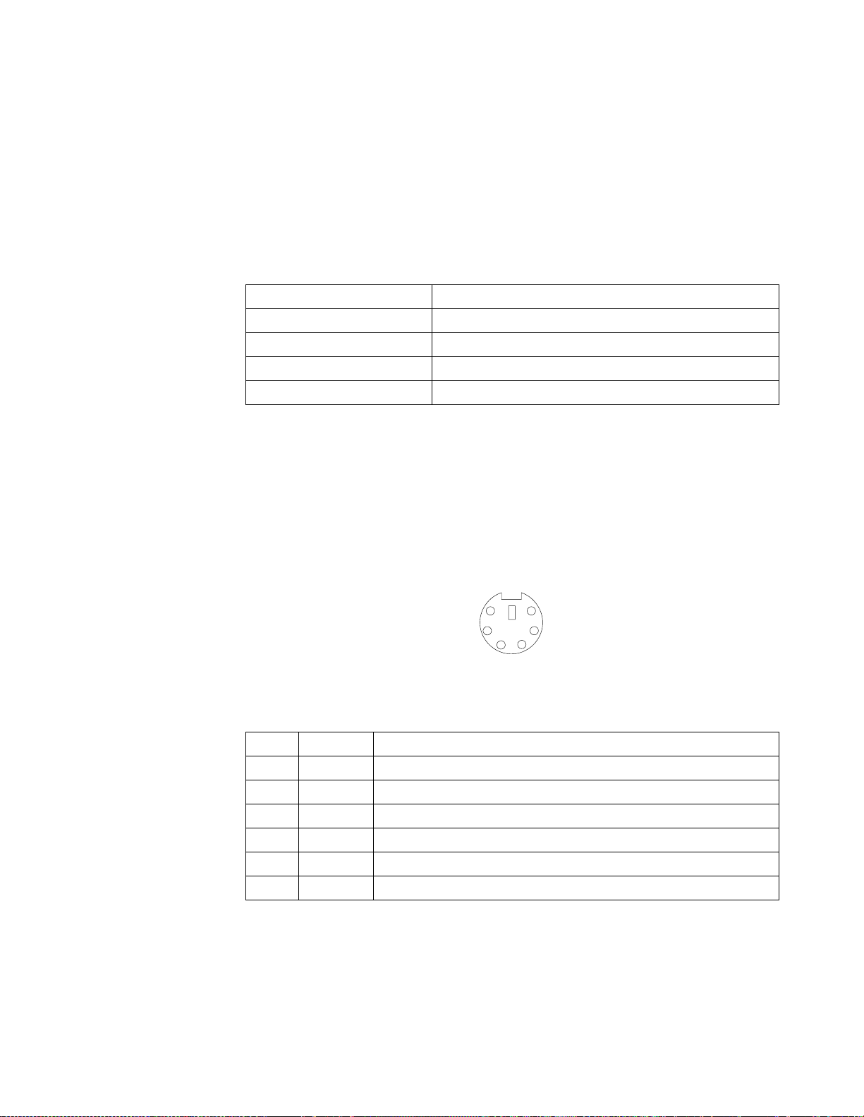
USB technology provides up to 12 megabits-per-second (Mbps) speed with a
maximum of 127 external devices and a maximum signal distance of five meters (16
ft) per segment.
USB-port connectors
Each USB port has an external connector on the rear of the server for attaching USBcompatible devices.
The following table shows the pin-number assignments for the USB-port connectors
on the rear of the server.
1+5 V dc
2-Data
3+Data
4Ground
Table 6. USB-port connector pin-number assignments
Keyboard port
There is one keyboard port on the rear of the server.
Note: If you attach a standard (non-USB) keyboard to the keyboard connector, the
USB ports and devices will be disabled during the power-on self-test (POST).
Pin Signal
The following table shows the pin-number a ssignments for the keyboard connector
on the rear of the server.
6
4
1
2
Pin I/O Signal
1I/O Data
2N/AReserved
3N/AGround
4 N/A +5 V dc
5I/O Clock
6N/AReserved
Table 7. Keyboard connector pin-number assignments
Auxiliary-device (pointing device) port
5
3
The rear of the server has one auxiliary-device port that supports a mouse or other
pointing device.
Chapter 5. Installing options 65
Page 76

The following table shows the pin-number assignments for the auxiliary-device
connector on the rear of the server.
Pin Signal
1Data
2 Reserved
3Ground
4+5 V dc
5Clock
6 Reserved
Table 8. Auxiliary-device connector pin-number assignments
Video port
Your server comes with an integrated super video graphics array (SVGA) video
controller. This controller is not removable, but you can disable it by installing a PCI
video adapter.
Note: If you install a PCI video adapter, the server BIOS code will automatically
6
4
2
disable the integrated video controller.
5
3
1
The following table shows the pin-number assignments for the 15-pin analog video
connector on the rear of the server.
5
1
1115
Pin Signal Pin Signal Pin Signal
1Analog red 6Red
return
2 Analog green or
monochrome
3Analog blue 8Blue
4 Not connected 9 PIN 14 Vertical synchronization (Vsync)
5 Digital return 10 Digital
7 Green
return
return
return
11 Not connected
12 DDC SDA
13 Horizontal synchronization
(Hsync)
15 DDC SCL
Table 9. Video-port connector pin-number assignments
66 IBM® xSeries 220 User’s Reference
Page 77

SCSI port
Your server has an integrated small computer system interface (SCSI) controller with
an internal connector (J41) on the system board. This controller supports an Ultra160
SCSI internal channel. This channel supports up to 15 SCSI devices. In addition, this
controller uses:
• Double-transition clocking to achieve high transfer rates
• Domain name validation to negotiate compatible data transfer speeds with each
• Cyclic-redundancy checking (CRC), instead of the usual parity checking, to
• An active terminator on the system board for SCSI bus termination
If you install a SCSI adapter in your server, you can use its SCSI connector to connect
different types of SCSI devices.
Note: If you install a PCI RAID adapter, you can move the SCSI cable from the
SCSI cabling requirements
For non-hot-swap drive models, you can install five internal S C SI devices by using
the SCSI cable that comes with the server. For hot-swap drive models, you can install
three hot-swap drives plus one non-hot-swap drive by using the SCSI cable that
comes with the server. If you plan to attach external SCSI devices, you must install an
optional SCSI adapter and order additional SCSI cables. To select and order the correct
cables for use with internal or external devices, contact your IBM reseller or IBM
marketing representative. For information about the maximum length of SCSI cable
between the terminated ends of the cable, refer to the ANSI SCSI standar ds . Adhering
to these standards will help ensure that your server operates properly.
device
significantly improve data reliability
system-board SCSI connector to an internal channel connector on the RAID
adapter if you want to control the internal drives from the adapter.
Setting SCSI IDs
Each SCSI device that is connected to a SCSI controller must have a unique SCSI ID.
This ID enables the SCSI controller to identify the device and ensure that different
devices on the same SCSI channel do not attempt to transf er data simultaneously.
SCSI devices that are connected to different SCSI channels can have duplicate SCSI
IDs. SCSI IDs for hot-swap drives are automatically set by the hot-swap back plane.
For hot-swap drives, bay 7 has ID 0, bay 6 has ID 1, and bay 5 has ID 2. Fo r non-hotswap drives, refer to the information that comes with the drives for instructions to set
their SCSI IDs.
External SCSI devices
To install external SCSI devices, you must first install an o ptional SCSI PCI adapter.
Refer to the information that is provided with the device for instructions to set its SCSI
ID.
Chapter 5. Installing options 67
Page 78

SCSI connector pin-number assignments
The following table shows the pin-number assignments for the 68-pin SCSI connector.
34
1
68
Pin Signal Pin Signal
1 +Data 12 35 -Data 12
2 +Data 13 36 -Data 13
3 +Data 14 37 -Data 14
4 +Data 15 38 -Data 15
5 +Data P1 39 -Data P1
6 +Data 0 40 -Data 0
7 +Data1 41 -Data 1
8 +Data 2 42 -Data 2
9 +Data 3 43 -Data 3
10 +D ata 4 44 -Data 4
11 +D ata 5 45 -Data 5
12 +D ata 6 46 -Data 6
13 +D ata 7 47 -Data 7
14 +D ata P 48 -Data P
35
15 Ground 49 Ground
16 DIFFSENS 50 Ground
17 Term power 51 Term power
18 Term power 52 Term power
19 Reserved 53 Reserved
20 Ground 54 Ground
21 +Attention 55 -Attention
22 Ground 56 Ground
23 +Busy 57 -Busy
24 +Acknowledge 58 -Acknowledge
25 +Reset 59 -Reset
26 +Message 60 -Message
27 +Select 61 -Select
28 +Control/Data 62 -Control/Data
29 +Request 63 -Request
30 +Input/Output 64 -Input/Output
Table 10. 68-pin SCSI connector pin-numb er assign men ts
68 IBM® xSeries 220 User’s Reference
Page 79

Pin Signal Pin Signal
31 +D ata 8 65 -Data 8
32 +D ata 9 66 -Data9
33 +D ata 10 67 -Data 10
34 +D ata 11 68 -Data 11
Table 10. 68-pin SCSI connector pin-numb er assign men ts
Ethernet port
Your server comes with an integrated Ethernet controller. This controller provides an
interface for connecting to 10-Mbps or 100-Mbps networks and provides full-duplex
(FDX) capability, which enables simultaneous transm ission and reception of data on
the Ethernet local area network (LAN).
To access the Ethernet port, connect a Category 3, 4, or 5 unshielded twisted-pair
(UTP) cable to the RJ-45 connector on the rear of the server.
Note: The 100BASE-TX Fast Ethernet standard requires that the cabling in the
Configuring the Ethernet controller
When you connect your server to the network, the Ethernet controller automatically
detects the data-transfer rate (10 Mbps or 100 Mbps) on the network and then sets the
controller to operate at the appropriate rate. In add ition, if the Ethernet port tha t your
server is connected to supports auto-negotiation, the Ethernet controller will set the
appropriate duplex state. That is, the Ethernet controller will adjust to the network
data rate, whether the data rate is standard Ethernet (10BASE-T), Fast Ethernet
(100BASE-TX), half duplex (HDX), or full duplex (FDX). The controller supports half-
duplex (HDX) and full-duplex (FDX) modes at both speeds.
network be Category 5 or higher.
The Ethernet controller is a PCI Plug and Play device. Yo u do not n eed to set any
jumpers or configure the controller for your operating system before you use the
Ethernet controller. However, you must install a device driver to enable your
operating system to address the Ethernet controller. The device drivers are provided
on the ServerGuide CDs.
Failover for redundant Ethernet
The IBM Netfinity 10/100 Ethernet Adapter or the IBM 10/100 Etherjet™ PCI family
of adapters are optional redundant network interface cards (NIC adapters) that you
can install in your server. If you install this NIC adapter and connect it to the same
logical segment as the primary Ethernet controller, you can configure the server to
support a failover function. Yo u can configure either the integrated Ethernet controller
or the NIC adapter as the primary Ethernet controller. In failover mode, if the primary
Ethernet controller detects a link failure, all Ethernet traffic that is associated with it is
switched to the redundant (secondary) controller. This switching occurs without any
user intervention. When the primary link is restored to an operational state, the
Ethernet traffic switches back to the primary Ethernet controller.
High-performance Ethernet modes
Your Ethernet controller supports optional modes, such as teaming, priority packets,
and virtual LANs, which provide higher performance and throughput for your
server.
Chapter 5. Installing options 69
Page 80

Teaming Mode: Your Ethernet controller provides options, called teaming options.
These options increase throughput and fault tolerance when running with Windows
NT 4.0 or NetWare 4.1x or later.
• Adapter fault tolerance (AFT) provides automatic redundancy for your adapter .
If the primary adapter fails, the secondary adapter takes over. Adapt e r fa ult
tolerance supports from two to four adapters per team.
• Adaptive load balancing (ALB) enables you to balance the transmission data
flow among two to four adapters. ALB also includes the AFT option. You can use
ALB with any 100BASE-TX switch.
• Cisco Fast EtherChannel (FEC) creates a team of two to four adapters to
increase transmission and reception thoughput. FE C also includes the AFT
option. You can use FEC only with a switch that has FEC capability.
T eaming requires you to install at least one additional Ethernet adapter. For additional
information about the teaming modes, refer to the documentation that comes with
these additional adapters.
Priority Packet Mode: Priority Packet is a traffic-prioritization utility that you can
use to set up filters to process high-priority traffic before normal traffic. You can send
information from critical nodes or applications with an indicated priority. Because
you set this priority at the host or entry point of the network, the network devices can
base forwarding decisions on priority information that is defined in the packet.
Priority Packet information is available on the IBM Networking Web site at
http://www.ibm.com/networking/support
Priority Packet prioritizes traffic based on priority filters. These are parameters that
you assign to outgoing (transmit) packets. Using the Priority Filter Wizard, you can
set up predefined or custom priority filters based on a node (MAC) address, Ethernet
type, or by various properties of the protocol and port. Priority Packet provides two
different methods for prioritizing traffic: IEEE 802.1p tagging and High Priority
Queue.
IEEE 802.1p is a new IEEE standard for tagging, or adding additional bytes of
information to packets with different priority levels. Packets are tagged with 4
additional bytes, which increase the packet size and indicate a priority level. When
you send these packets out on the network, the higher priority packets are transferr ed
first. Priority packet tagging (also known as Traffic Class Expediting) enables the
adapter to work with other elements of the network (such as switches and routers) to
deliver priority packets first. You can assign specific priority levels from 0 (low) to 7
(high).
Y ou can assign values to packets based on their priority when you use the IEEE 802.1p
standard for packet tagging. This method requires a network infrastructure that
supports packet tagging. The routing devices that receive and transfer these packets
on your network must support 802 . 1p f or ta gging to be effective.
After you set up the priority filter in Priority Packet, you must start IBMSet and select
802.1p/802.1Q Tagging on the Advanced tab.
Note: IEEE 802.1p tagging increases the size of the packets that it tags. Some hubs
and switches will not recognize the larger packets and will drop them. Check
your hub or switch documentation to see if they support 802.1p. (You can
configure the switch to strip the tags from the packets and send it on to the
next destination as normal traffic.) If these devices do not support 802.1p or if
you are not sure, use High Priority Queue (HPQ) to prioritize network traffic.
70 IBM® xSeries 220 User’s Reference
Page 81

The requirements for effectively using IEEE 802.1p tagging are:
• The other devices receiving and routing 802.1p tagged packets must support
802.1p.
• The adapters on these devices must support 802.1p. The Ethernet controller in
your xSeries 220 and all IBM Netfinity10/100 Ethe rnet Security Adapters
support 802.1p.
• The adapter cannot be assigned to an adapter team.
• If you are setting up VLANs and packet tagging on the same adapter,
802.1p/802.1Q tagging must be enabled on the IBMSet Advanced tab.
If your network infrastructure devices do not support IEEE 802.1p or you ar e not sur e,
you can still define filters and send packets as high priority. While High Priority
Queue (HPQ) does not provide the precise priority levels of 802.1p tagging, it does
assign traffic as either high or low priority and sends high-priority packets first.
Therefore, if there are multiple applications on a system that is sending packets, the
packets from the application with a filter are sent out first. HPQ does not change
network routing, nor does it add any information to the packets.
To assign HPQ, you can specify it using Priority Packet when you create or assign a
filter.
To effectively use HPQ tagging, the adapter cannot be assigned to an adapter team.
Virtual LAN Mode: A virtual LAN (VLAN) is a logical grouping of network devices
that are put together as a LAN, regardless of their physical grouping or collision
domains. Using VLANs increases network performance and improves network
security.
VLANs offer you the ability to group users and devices together into logical
workgroups. This can simplify network administration when you are connecting
clients to servers that are geographically disp ersed across a building, campus, or
enterprise network.
Normally, VLANs are configur ed at the switch, and any computer can be a member of
one VLAN per installed network adapter . Your Ethernet controller supersedes this by
communicating directly with the switch, enablin g multiple VLANs on a single
network adapter (up to 64 VLANs).
To set up VLAN membership, your Ethernet controller must be attached to a switch
that has VLAN capability. You also need to use Windows NT 4.0 or later, or Novell
NetWare 4.1x or later.
Notes:
1. Windows NT versions prior to 4.0 do not support VLANs.
2. VLANs require NT 4.0 with Service Pack 3.0 and the NDIS driver hotfix from
Microsoft.
3. In Windows NT, VLANs cannot be implemented on controllers that have been
configured for teaming options. NetWare can support teaming options and
VLANs on the same adapters.
Chapter 5. Installing options 71
Page 82

To join a VLAN from Windows NT 4.0:
1. Create a VLAN on the switch. Use the parameters that you assign there to join the
VLAN from the server. Refer to your switch documentation for more information.
2. In the Control Panel window, double-click the Network icon.
3. On the Adapters tab, select the adapter that you want to be on the VLAN, and
click Properties.
4. In IBMSet, click Join VLAN. Note that VLANs cannot be assigned to adapters
that are already defined to have an adapter teaming option.
5. Type the VLAN ID and VLAN name. The VLAN ID must match the VLAN ID of
the switch. The ID range is from 1 to 1000. The VLAN name is for information
only and does not need to match the name on the switch.
6. Click Join VLAN. Repeat steps 3 through 5 for each VLAN that you want the
server to join. The VLANs that you add are listed on the Adapters tab.
7. Click Close and restart the computer.
Ethernet port connector
The following table shows the pin-number assignments for the RJ-45 connector. These
assignments apply to both 10BASE-T and 100BASE-TX devices.
Pin Signal Pin Signal
1 +Transmit data 5 Not connected
2 -Transmit data 6 -Receive data
3+Receive data 7Not connected
4 Not connected 8 Not connected
Table 11. Ethernet RJ-45 connector pin-number assignments
If you plan to use the Wake on LAN function in the server , you must install a Wake on
LAN-enabled network interface car d (NIC adapter) in PCI slot 1, and install the Wake
on LAN cable that comes with the Wake on LAN adapter to connect this adapter to
the system board. You must use a Wake on LAN-enabled adapter as identified in the
xSeries 220 ServerProven list at http://www.ibm.com/pc/compat/. Only PCI slot 1
supports a W ake on LAN-enabled adapter. For additional information on the W ake on
LAN function, adapter, and cables, refer to the documentation that comes with the
Wake on LAN adapter.
72 IBM® xSeries 220 User’s Reference
Page 83

Chapter 6. Solving problems
This section provides basic troubleshooting information to help you resolve some
common problems that might occur with your server.
If you cannot locate and correct the problem using the information in this section,
refer to “Getting help, service, and information” on page 115 for more information.
Diagnostic tools overview
The following tools are available to help you identify and resolve hardware-related
problems:
• POST beep codes, error messages, and error logs
The power-on self-test (POST) generates beep codes and messages to indicate
successful t es t c o mpletion or th e de t ec t i on of a problem. See “POST” on page 75
for more information.
• Diagnostic programs and error messages
The server diagnostic programs are stored in upgradeable read-only memory
(ROM) on the system board. These programs are the primary method of testing
the major components of your server. See “Diagnostic programs and error
messages” on page 87 for more information.
• Diagnostic LEDs
Your server has light-emitting diodes (LEDs) to help you identify pr oblems with
server components. These LEDs are part of the diagnostics that are built into
your server. Use the illuminated LEDs to identify the failing or inco rrectly
installed components. See “Diagnostic LEDs” on page 99 for more information.
• Troubleshooting charts
These charts list problem symptoms and suggested steps to correct the
problems. See the “Troubleshooting charts” on page 101 for more information.
• Customized support page
You can create a customized support page that is specific to your hardware,
complete with Frequently Asked Questions, Parts Information, Te chnical Hints
and Tips, and Downloadable files. In addition, you can choose to receive
electronic mail (e-mail) notifications whenever new information becomes
available about your registered products.
After you register and profile your xSeries products, you can diagnose problems
using the IBM Online Assistant, and you can participate in the IBM discussion
forum. For more detailed information about registering and creating a
customized profile for your IBM products, visit the following addresses on the
Web:
— http://www.ibm.com/pc/register
— http://www.ibm.com/pc/support
© Copyright IBM Corp. 2000 73
Page 84

S
erver Support
Server working
properly?
Yes
No
Check all cables for loose connections
and verify that all optional devices you
installed are on the Server Proven list.
You can view the Server Proven list at:
http://www.ibm.com/pc/compat
Problem
solved?
Yes
No
Register and profile your server
After you register and profile, you will be able to:
• Diagnose problems using the IBM Online Assistant
• Participate in the IBM discussion forum
• Receive e-mail notifications of technical updates
related to your profiled products
Register at:
Profile at:
http://www.ibm.com/pc/register
http://www.ibm.com/pc/support
Use the troubleshooting
information provided with
your server to determine
the cause of the problem
and the action to take.
Problem
solved?
Yes
No
Flash the latest levels of BIOS,
service processor, diagnostics,
and RAID code.
You can download this code at:
http://www.ibm.com/pc/support
Yes
Problem
solved?
You can view a list of
IBM Help Center phone numbers at:
http://www.ibm.com/pc/support
No
Phone an
IBM Help Center
74 IBM® xSeries 220 User’s Reference
Page 85

POST
When you turn on the server, it performs a series of tests to check the operation of
server components and some of the options installed in the server. This series of tests
is called the power-on self-test, or POST.
If POST finishes without detecting any problems, a single beep sounds, and the first
window of your operating system or application program appears.
If POST detects a problem, more than one beep sounds, and an error message appears
on your screen. See “POST beep code descriptions” and “POST error messages” on
page 79 for more information.
Notes:
1. If you have a power-on password set, you must type the password and press
Enter, when prompted, before POST will continue.
2. A single problem might cause several error messages. When this occurs, work to
correct the cause of the first error message. After you correct the cause of the first
error message, the other error messages usually will not occur the next time you
run the test.
POST beep code descriptions
Beep codes are sounded in a series of beeps. For example, a 1-2-4 beep code sounds
like one beep, a pause, two consecutive beeps, another pause, and four more
consecutive beeps.
The possible types of beep codes that your server might emit include the following:
No beeps If no beep occurs after your server completes POST, call for service.
Continuous beep
Your startup (boot) microprocessor has failed, or your system board or
speaker subsystem might contain a failing component. If the system
continues through POST with no errors, call for service. If no video appears,
the startup microprocessor has failed; replace the startup microprocessor.
One short beep
One beep indicates that your server successfully completed POST. POST
detected no configuration or functional errors. One beep also occurs after
your server completes POST, if you type an incorrect power-on password.
Two short be eps
POST encountered an error. The Configuration/Setup Utility program will
display additional information; follow the instructions that appear on the
screen. See “POST error messages” on page 79 for descriptions of the text
messages that might appear.
Three short beep s
A system-memory error has occurred. This combination occurs only if the
video basic input/output system (BIOS) cannot display the error message.
Replace the failing memory module.
Chapter 6. Solving problems 75
Page 86

Repeating short beeps
The system board might contain a failing component, your keyboard might
be defective, or a key on the keyboard might be stuck. Ensure that:
1. Nothing is resting on the keyboard and pressing a key.
2. No key is stuck.
3. The keyboard cable is connected correctly to the keyboard and to the
correct connector on the server.
Running the diagnostic tests can isolate the server component that failed, but
you must have your system serviced. If the error message remains, call for
service.
Note: If you just connected a new mouse or other pointing device, turn off
the server and disconnect that device. Wa it at least 5 seconds; then,
turn on the server. If the error message goes away, replace the device.
One long and one short beep
POST encountered an error on a video adapter. If you are using the integrated
video controller, call for service. If you are using an optional video adapter,
replace the failing video adapter.
One long and two short beeps
A video I/O adapter ROM is not readable, or the video subsystem is
defective. If you hear this beep combination twice, both the system board and
an optional video adapter have failed the test. This beep combination might
also indicate that the system board contains a failing component.
One long and three short beeps
The system-board video subsystem has not detected a monitor conn ection to
the server. Ensure that the monitor is connected to the server. If the problem
persists, replace the monitor.
Two long and two short beeps
POST does not support the optional video adapter. This beep combination
occurs when you install a video adapter that is incompatible with your server.
Replace the optional video adapter with one that the server supports, or use
the integrated video controller.
76 IBM® xSeries 220 User’s Reference
Page 87

POST beep codes
Beep code Description Action
1-1-2 Microprocessor register test has failed. Call for service.
1-1-3 CMOS write/read te st has failed.
1-1-4 BIOS ROM checksum has failed.
1-2-1 Programmable Interval Timer test has failed.
1-2-2 DMA initialization has failed.
1-2-3 DMA page register write/read test has failed.
1-4-3 Interrupt vector loading test has failed.
2-1-1 Secondary DMA register test has failed.
2-1-2 Primary DMA register test has failed.
2-1-3 Primary interrupt mask register test has failed.
2-1-4 Secondary interrupt mask register test has faile d.
2-2-1 Interrupt vector loading has failed.
2-2-2 Keyboard controller test has failed.
2-2-3 CMOS power failure and checksum checks have failed.
2-2-4 CMOS configuration information validation has failed. Call for service.
2-3-2 Screen memory test has failed.
2-3-3 Screen retrace tests have failed.
2-3-4 Search for video ROM has failed.
2-4-1 Screen test indicates the screen is operable.
3-1-1 Timer tick interrupt test has failed.
3-1-2 Interval timer channel 2 test has failed.
3-1-3 RAM test has failed above address hex 0FFFF.
3-1-4 Time-of-Day clock test has failed.
3-2-1 Serial port test has failed.
3-2-2 Parallel po rt test has failed.
3-2-4 Comparison of CMOS memory size against actual has
failed.
2-3-1 3-3-2 Screen initialization has failed. I2C bus has failed. Turn off the
server and then
restart the ser ve r.
If the problem
persists, call for
service.
Table 12. POST beep codes
Chapter 6. Solving problems 77
Page 88

1-2-4 RAM refresh verification has failed. Reseat the
1-3-1 First 64 Kb RAM test has failed.
1-3-2 First 64 Kb RAM parity test has failed.
3-3-1 A memory size mismatch has occurred.
3-3-3 No memory has been detected in the system.
Attention: In some memory configurations, the 3-3-3 beep
code might sound du rin g P OS T follow ed by a blank sc r een.
If this occurs, you must restart the server three times to
force the system BIOS to reset the memory connector or
bank of connectors from Disabled to Enabled.
memory modules
or install a
memory module.
If the problem
persists, call for
service.
4-4-4 The I2C cable is attached and, the optional system-
management adapter is no t inst a lled in PCI slot 2 or not
functioning correctly.
1. Turn off the
server.
2. Verify that
the cable is
installed
correctly. If it
is not,
disconnect
the cable and
reconnect it
correctly.
3. Verify that
the optional
systemmanagement
adapter is
installed in
PCI slot 2. If
it is not,
remove the
systemmanagement
adapter from
the slot and
reinstall it in
PCI slot 2.
4. Verify that
the optional
systemmanagement
adapter is
functioning
correctly. If it
is not,
remove it
and call for
service.
If the problem
persists, call for
service.
Table 12. POST beep codes
78 IBM® xSeries 220 User’s Reference
Page 89

POST error messages
The following tables provide information about the POST error messages that can
appear during startup.
POST message Description
062 The server failed to boot on three consecutive attempts.
All caches are disabled. Repeatedly turning the server on and then off or resetting the server
might cause this problem.
Action: Start the Configuration/Setup Utility program and verify that all settings are
correct. Use the Cache Control selection in the Advanced Setup menu of the
Configuration/Setup Utility program to enable the caches.
If the problem persists, call for service. When the problem is corrected, be sure to enable the
caches.
101 102 106 An error occurred during the system board and microprocessor test.
Action: Call for service.
114 An adapter read-only memor y (ROM) error occurred.
Action: Remove the options . If you can start the server without the options installed,
reinstall each option one at a time and retest after each is reinstalled. When an
option fails, replace it.
If you cannot isolate and correct the pr ob lem, call for serv ic e.
129 An error was detected in the L1 cache of one of the microprocessors.
Action: 1. If you just installed a micr opr ocesso r, verify that the microprocesso r i s inst alled
and seated correctly.
2. If the problem persists, call for service.
151 A real-time clock (RTC) error occurred.
Action: Call for service.
161 The real-time clock battery has failed.
Action: Replace the battery yourself, or call for service.
You can use the server until you replace the battery. However, you must run the
Configuration/Setup Utility program and set the time and date and other custom settings each
time you turn on the server.
Table 13. POST error messages
Chapter 6. Solving problems 79
Page 90

POST message Description
162 A change in device configuration occurred. This error occurs under one or more of the following
conditions:
• A new device has been installed.
• A device has been moved to a different location or cable connection.
• A device has been removed or disconnected from a cable.
• A device is failing and is no longer recognized by the server as being installed.
• An external device is not turned on.
• An invalid checksum is detected in the battery-backed memory.
Action: Verify that all external devices are turned on. You must turn on external devices
before turning on the server.
If you did not add, remove, or change the location of a device, a device is probably failing.
Running the Diagnostic program might isolate the failing device.
If you cannot isolate and correct the pr ob lem, call for serv ic e.
163 The time of day has not been set.
Action: Set the correct date and time. If the date and time are set correctly and saved, but the
163 error message reappears, call for service.
Y ou can use the se rver until the syste m is serviced, but any applicati on progr ams that use the date
and time will be affected.
164 A change in the memory configuration occurred. This message might appear after you add or
remove memory.
Note: The server can be used with decreased memory capacity.
Action: 1. If POST error message 289 also o ccurred, follow the instructions for that error
message first.
2. If you just installed or removed memory, run the Configuration/Setup Utility
program; then, exit, saving the new configuration setti ngs.
If the message appears again, shut down the server, reseat the memory
modules, and restart the server.
If the problem persists, call for service.
175 A vital product data (VPD) error occurred.
Action: Call for service.
176 177 178 A security hardware error occurred.
Action: Check for indications that someone has tampered with the server. If no one has
tampered with the server, call for service.
184 The power-on password information stored in your server has been removed.
Action: From the Configuration/S etup Uti lity pr ogram m ain men u, select Sys tem Sec urity.
Then, follow the instructions on the screen.
If this information cannot be restored, call for service.
185 A power failure damaged the stored information about the drive-startup sequence.
Action: From the Configuration/Setup Utility program main menu, select Start Options;
then, follow the instructions on the screen.
If this information cannot be restored, call for service.
Table 13. POST error messages
80 IBM® xSeries 220 User’s Reference
Page 91

POST message Description
186 A system board or hardware error occurred.
Action: Call for service.
187 The VPD serial number is not set.
Action: The system serial number is set in t he VPD EEPROM a t the time of man ufacturing .
If the system board h as b een r eplaced, the system seria l nu mbe r w ill b e inv a lid a nd
should be set. From the main menu of the Configuration/Setup Utility program,
select System Information, then select Product Da ta.If the problem persists, call for
service.
188 A vital product data (VPD) error occurred.
Action: Call for service.
189 An attempt has been made to access the server with invalid passwords. After three incorrect
attempts, the server locks up; that is, the logon data fields are no longer available to the user.
201 An error occurred during the memory controller test. This error can be caused by:
• Incorrectly installed memory
• A failing memory module
• A system board problem
Action: 1. If you just installed memory, verify that th e new memory is correct for your
server. Also verify that the memory is installed and seated correctly.
2. If the problem persists, call for service.
229 An error was detected in the L2 cache of one of the microprocessors.
Action: 1. If you just installed a micr opr ocesso r, verify that the microprocesso r i s inst alled
and seated correctly.
2. If the problem persists, call for service.
289 An error occurred during POST memory tests, and a failing DIMM was disabled.
Note: You can use the server with decreased memory.
Action: 1. If you just installed memory, verify that th e new memory is correct for your
server. Also verify that the memory is installed and seated correctly. Start the
Configuration/Setup Utility program, and select Memory Settings from the
Advanced Setup menu to enable the DIMM.
2. If the problem remains, replace the failing DIMM.
If the problem persists, call for service.
301 303 An error occurred during the keyboard and keyboard controller test. These error messages also
might be accompanied by continuous beeping.
Action: Ensure that:
1. Nothing is resting on the keyboard and pressing a key.
2. No key is stuc k.
3. The keyboard cable is connected correctly to the keyboard and to the correct
connector on the server.
Running the diagnostic tests can isolate the server component tha t failed, but you must have your
system serviced. If the error message remains, call for service.
Note: If you just connected a new mouse or other pointing device, turn off the server and
disconnect that device. Wait at least 5 seconds; then, turn on the server. If the error
message goes away, replace the device.
Table 13. POST error messages
Chapter 6. Solving problems 81
Page 92

POST message Description
602 Invalid diskette boot record.
Action: 1. Replace the diskette.
2. If the problem persists, make sure that the diskette drive cables are correctly
and securely connected.
3. If the problem remains, replace the diskette drive.
If the problem persists, call for service.
604 An error occurred during a diskette drive test.
Action: 1. Verify that the Configuration/Setup Utility program correctly reflects the type
of diskette drive that you have installed.
2. Run the diagnostic tests. If the diagnostic tests fail, call for service.
662 A diskette drive configuration error occurred.
Action: If you removed a diskette drive, make sure that the diskette drive setting is correct
in the Configuration/Setup Utility program. If the setting is not correct, change it.
If the problem persists, call for service.
962 A parallel port configuration error occurred.
Action: If you changed a hardware option , make sure that th e pa ra llel por t set ting is correct
in the Configuration/Setup Utility program. If the setting is not correct, change it.
If the problem persists, call for service.
11xx An error occurred during the system-board serial port test.
Action: If you have a modem, serial printer, or other serial device attached to your server,
verify that the serial cable is connected correctly. If it is, use the following
procedure:
1. Turn off the server.
2. Disconnect the serial cable from the serial port.
3. Wait five seconds; then, turn on the server.
If the POST error message does not reappear, either the serial cable or the device is probably
failing. See the documentation that comes with the serial device for additional testing
information.
If the POST error message reappears, call for service.
1162 The serial port configuration conflicts with another device in the system.
Action: 1. Make sure that the IRQ and I/O port assignments n eeded by the serial port are
available.
2. If all interrupts are being used by adapters, you might need to remove an
adapter to make an i nterr upt ava ilable to the s erial port , or for ce ot he r ada pters
to share an interrupt.
1800 A PCI adapter ha s requested a hardware interrupt that is not available.
Action: 1. Make sure that the PCI adapter and all other adapters are set correctly in the
Configuration/Setup Utility program. If the interrupt resource settings are not
correct, change the settings.
2. If all interrupts are being used by other adapters, you might need to remove an
adapter to make an interrupt available to the PCI adapter, or force other
adapters to share an interrupt.
Table 13. POST error messages
82 IBM® xSeries 220 User’s Reference
Page 93

POST message Description
1962 No valid startup devices were found. The system cannot find the startup drive or operating
system.
Action: Be sure that the drive you want to start from is in the startup sequence.
1. Select Start Options from the Configuration/Setup Utility program main
menu. If you are unable to set the startup sequence, call for servi ce.
2. Check the list of startup devices in the Startup de vice data fields. Is the drive
you want to start from in the startup sequence?
Yes Exit from this screen; then, select Exit Setup to exit the
Configuration/Setup menu. Go to step 3.
No Follow the instructions on the screen to add the drive; then, save the
changes and exit the Configuration/Setup menu. Restart the server.
3. Is an operating system installed?
Yes Turn off the server. Go to step 4.
No Install the operating system in your server; then, follow your
operating system instructions to shut down and restart the server.
4. During server startup, watch for messages indicating a hardware problem.
If the same error message appears, call for service.
2400 An error occu rred dur ing the testing of the video contr oller on the sys tem boar d. This err or can be
caused by a failing monit or, a failing system board, or a failing video adapter (if one is installed).
Action: Verify that the monitor is connected correctly to the video connector. If the monitor
is connected correctly, call for service.
2462 A video memory configuration error occurred.
Action: Make sure that the monitor cables ar e corr ectly a nd secur ely connected to t he server.
If the problem persists, call for service.
5962 An IDE CD-ROM configuration error occurred.
Action: Check the signal and power cable connections to the CD-ROM drive.
If the problem persists, call for service.
8603 An error occurred during the mouse (pointing device) controller test. The addition or removal of
a mouse, or a failing system board can cause this error.
Note: This error also can occur if electrical power was lost for a very brief period and then
restored. In this case, turn off the server for at least 5 seconds; then, turn it back on.
Action: Ensure that the keyboard and mouse (pointing device) are attached to the correct
connectors. If they are connected correctly, use the following procedure:
1. Turn off the server.
2. Disconnect the mouse from the server .
3. T urn on the server.
If the POST error message does not reappear, the mouse is probably failing. See the
documentation that comes with the mouse for additional testing information. If the problem
remains, replace the mouse or pointing device.
If the POST error message reappears, run the diagnostic tests to isolate the problem. If the
diagnostic tests do not find a problem and the POST error message remains, call for service.
Table 13. POST error messages
Chapter 6. Solving problems 83
Page 94

POST message Description
00012000 Processor machine check.
Action: 1. Update the system BIOS.
2. If the problem persists, replace the microprocessor.
00019501 Pro c essor 1 is not functioning .
Action: Replace microprocessor 1.
If the problem persists, call for service.
00019502 Pro c essor 2 is not functioning .
Action: Replace microprocessor 2.
If the problem persists, call for service.
00019701 Processor 1 failed the built-in self-test.
Action: Replace microprocessor 1.
If the problem persists, call for service.
00019702 Processor 2 failed the built-in self-test.
Action: Replace microprocessor 2.
If the problem persists, call for service.
00180100 A PCI adapter has requested memory resources that are not available.
Action: 1. Make sure that the PCI adapter and all other adapters are set correctly in the
Configuration/Setup Utility program. If the memory resource settings are not
correct, change the settings.
2. If all memory resources are being used, you might need to remove an adapter
to make memory available to the PCI adapter. Disabling the adapter BIOS on
the adapter might correct the error. Refer to the documentation provided with
the adapter.
00180200 A PCI adapter has requested an I/O address that is not available, or the PCI adapter might be
defective.
Action: 1. Make sure that the I/O address for the PCI adapter and all other adapters are
set correctly in the Configuration/Setup Utility program.
2. If the I/O port resour ce settings ar e corr ect, the PCI adapter mig ht be defective.
Call for service.
00180300 A PCI adapter has requested a memory address that is not available, or the PCI adapter might be
defective.
Action: 1. Make sure that the memory address for all other adapters are set correctly in
the Configuration/Setup Utilit y pr og ra m . If the memory r esource settings ar e
not correct, change the settings.
2. If the memory resource settings are corr ect, th e PCI adapter might be defective.
Call for service.
00180400 A PCI adapter has requested a memory address that is not available.
Action: If all memory addresses are being used, you might need to remove an adapter to
make memory addre ss spac e av ai lab l e to the PC I ada pter. Disabling the adapter
BIOS on the adapter might correct the error. Refer to the documentation provided
with the adapter.
Table 13. POST error messages
84 IBM® xSeries 220 User’s Reference
Page 95

POST message Description
00180500 A PCI adapter ROM error occurred.
Action: Remove the PCI adapte rs. If you can start the server without the adapters, reinstall
each adapter one a t a time and r e test aft er e ach is reinstalled. W hen an adap ter fail s,
replace it.
If you cannot isolate and correct the pr ob lem, call for serv ic e.
00180600 A PCI-to-PCI bridge error occurred. More than one PCI bus tried to access memory below 1 MB.
Action: Remove the PCI adapter that ha s the PCI bridge. If you can start the server without
the adapter, reinstall and retest the adapter. If the adapter fails, replace it.
If you cannot isolate and correct the pr ob lem, call for serv ic e.
00180700 xxxxyyyy Planar PCI device does not respond or disabled by user. (Where xxxx is the PCI vendor
ID and yyyy is the PCI device ID.)
Action: Start the Configuration/Setup Utility program, select Devices and I/O Ports, and
make sure that the device is enabled. If the problem persists, call for service.
00180800 An unsupported PCI device is installed.
Action: Remove the PCI adapte rs. If you can start the server without the adapters, reinstall
each adapter one a t a time and r e test aft er e ach is reinstalled. W hen an adap ter fail s,
replace it.
If the problem persists, call for service.
00181000 PCI error.
Action: Remove the PCI adapte rs. If you can start the server without the adapters, reinstall
each adapter one a t a time and r e test aft er e ach is reinstalled. W hen an adap ter fail s,
replace it.
If the problem persists, call for service.
01295085 The ECC checking hardware test failed.
Action: Call for service.
01298001 No update data is available for p roce ssor 1.
Action: Update the system BI OS to a leve l tha t support s th e micr opr oc essors i nstal led in the
server.
01298002 No update data is available for p roce ssor 2.
Action: Update the system BI OS to a leve l tha t support s th e micr opr oc essors i nstal led in the
server.
01298101 T he update data for processor 1 is incorrect.
Action: Update the system BI OS to a leve l tha t support s th e micr opr oc essors i nstal led in the
server.
01298102 T he update data for processor 2 is incorrect.
Action: Update the system BI OS to a leve l tha t support s th e micr opr oc essors i nstal led in the
server.
01298200 Microprocessor speed mismatch.
Action: The microproces sors installed do not r u n at th e same speed; install m ic roprocessors
with identical speeds.
I9990301 A hard d isk drive error occurred.
Action: Call for service.
Table 13. POST error messages
Chapter 6. Solving problems 85
Page 96

POST message Description
I9990305 POST could not find an operating system.
Action: Install an operating system. If you have already installed the operating system,
check the drive startup sequence. If the drive sequence is correct, run the di agnostic
tests to verify that the hard disk drive is functioning correctly. If there is a problem
with the hard disk drive (such as a bad sector), you might need to reinstall the
operating system.
If you cannot reinstall the operating system, call for service.
I9990650 AC power has been restored.
Action: No action is required. This message appears each time AC power is restored to the
server after an AC power loss.
Other Numbers POST found an error.
Action: Follow the instructions on the screen.
Table 13. POST error messages
POST error log
The POST error log contains the three most recent error codes and messages that the
system generated during POST.
To view the contents of this error log, start the Configuration/Setup Utility program;
then, select Error Logs from the main menu.
Small computer system interface messages
The following table lists actions to take if you receive a SCSI error message.
Note: If your server does not have a hard disk drive, ignore any message that
indicates that the BIOS is not installed.
You will get these messages only when running the SCSISelect Utility.
86 IBM® xSeries 220 User’s Reference
Page 97

Table 14. SCSI messages
SCSI Messages Description
All One or more of the following might be causing the problem.
• A failing SCSI device (adapter, drive, controller)
• An improper SCSI configuration
• Duplicate SCSI IDs in the same SCSI chain
• An improperly installed SCSI terminator
• A defective SCSI terminator
• An improperly installed cable
• A defective cable
Action:
Verify that:
• The external SCSI devices are turned on. External SCSI devices must
be turned on before the server.
• The cables for all external SCSI devices are connected correctly.
• The last device in each SCSI chain is terminated properly.
• The SCSI devices are configured correctly.
If the above items are correct, run the diagnostic programs to obtain
additional information about the failing device. If the error remains or
recurs, call for service.
Diagnostic programs and error messages
The server diagnostic programs are stored in upgradeable read-only memory (ROM)
on the system board. These programs are the primary method of testing the major
components of your server.
Diagnostic error messages indicate that a problem exists; they are not intended to be
used to identify a failing part. Troubleshooting and servicing of complex problems
that are indicated by error messages should be performed by trained service
personnel.
Sometimes the first error to occur causes additional errors. In this case, the server
displays more than one error message. Always follow the suggested action
instructions for the first error message that appears.
The following sections contain the error codes that might appea r in the detailed test
log and summary log when runnin g the diagnostic programs.
The error code format is as follows:
fff-ttt-iii-date-cc-text message
where:
fff is the three-digit function code that indicates th e fu nction being tested when
the error occurred. For example, function code 089 is for the microprocessor.
ttt is th e three-digit failure code that indicates the exact test f ai lure that was
encountered. (These codes ar e fo r trained service personnel and ar e des cribed
in the Hardware Maintenance Manual.)
Chapter 6. Solving problems 87
Page 98

iii is the three-digit device ID. (These codes are for trained service personnel and
are described in the Hardware Maintenance Manual.)
date is the date that the diagnostic test was run and the error was recorded.
cc is the check digit that is used to verify the validity of the information.
text message
is the diagnostic message that indicates the reason for the problem.
Text messages
The diagnostic text message format is as follows:
Function name: Result (test specific string)
where:
Function name
is the name of the function being tested when the error occurred. This
corresponds to the function code (fff) given in the previous list.
Result can be one of the following:
Passed This result occurs when the diagnostic test completes w ithout any
errors.
Failed This result occurs when the diagnostic test discovers an error.
User Aborted
This result occurs when you stop the diagnostic test before it is
complete.
Not Applicable
This result occurs when you specify a diagnostic test for a device that
is not present.
Aborted This result occurs when the test could not proceed because of the
system configuration.
Warning This result occurs when a possible problem is reported during the
diagnostic test, such as when a device that is to be tested is not
installed.
Test Specific String
This is additional information that you can use to analyze the problem.
Starting the diagnostic programs
You can press F1 while running the diagnostic programs to obtain Help information.
You also can press F1 from within a help screen to obtain online documentation from
which you can select different categories. To exit from the Help information and
return to where you left off, press Esc.
To start the diagnostic pr o gra ms :
1. Turn on the server and watch the screen.
2. When the message F2 for Diagnostics appears, press F2.
3. Type in the appropriate password; then, press Enter.
4. Select either Extended or Basic from the top of the screen.
88 IBM® xSeries 220 User’s Reference
Page 99

5. When the Diagnostic Programs screen appears, select the test you want to run
from the list that appears; then, follow the instructions on the screen.
Notes:
a. If the server stops during testing and you cannot continue, restart the server
and try running the diagnostic programs again. If the problem persists, call
for service.
b. The keyboard and mouse (pointing device) tests a ssume that a keyboard and
mouse are attached to the server.
c. If you run the diagnostic programs with no mouse attached to your server,
you will not be able to navigate between test categories using the Next Cat
and Prev Cat buttons. All othe r functions provided by mouse-selectable
buttons are also available using the function keys.
d. You can test the USB keyboard by using the regular keyboard test. The
regular mouse test can test a USB mouse. Also, you can run the USB interface
test only if there are no USB devices attached.
e. Y ou can view server configuration information (such as system configuration,
memory contents, interrupt request (IRQ) use, direct memory access (DMA)
use, device drivers, and so on) by selecting Hardware Info from the top of the
screen.
When the tests have completed, you can view the Test Log by selecting Utility from
the top of the screen.
If the hardware checks out OK but the problem persists during normal server
operations, a software error might be the cause. If you suspect a software problem,
refer to the information that comes with the software package.
Viewing the test log
The test log will not contain any info rmation until after the diagnostic program has
run.
Note: If you already are running the diagnostic programs, begin with step 3.
To view the test log:
1. Turn on the server and watch the screen.
If the server is on, shut down your operating system and restart the server.
2. When the message F2 for Diagnostics appears, press F2.
If a power-on password is set, the server prompts you for it. Type in the
appropriate password; then, press Enter.
3. When the Diagnostic Programs screen appears, select Utility from the top of the
screen.
4. Select View Test Log from the list that appears; then, follow the instructions on
the screen.
The system maintains the test-log data while the server is powered on. When you
turn off the power to the server, the test log is cleared.
Chapter 6. Solving problems 89
Page 100

Diagnostic error message tables
The following tables provide descriptions of the error messages that might appear
when you run the diagnostic programs.
Attention: If diagnostic error messages appear that are not listed in the following
tables, make sure that your server has the latest levels of BIOS, ServeRAID, and
diagnostics microcode installed.
Code Function Result Text message Action
001 Core system Failed Processor board, ECC Test Call for service.
System board
005 Video port Processor and system boards
011 Serial port Integrated serial port
014 Parallel port Integrated parallel port
015 USB interface Aborted Can NOT test USB interface while it is in use.
Note: If you have a USB keyboard or mouse
attached, you cannot run the diagnostic
program for the USB interf ac e.
Failed System board Call for service.
020 PCI interface Failed System board Call for service.
030 SCSI interface Fai led SCSI adapter in slot n failed register/counter/ power
test
(where n is the slot number of the failing adapter)
SCSI controller on system boar d failed
register/counter/power test
1. Turn off the server.
2. Replace the USB
keyboard and
mouse with a
standard keyboard
and mouse.
3. Turn on the server.
4. Run the diagnostic
test again.
5. If the test still
aborts with no USB
devices attached,
follow Failed action
below.
Refer to the informati on
provided with the
adapter for instructions.
If the problem persists,
call for service.
Call for service.
90 IBM® xSeries 220 User’s Reference
 Loading...