

Page 1
Page 2

Note
Before using this information and the product it supports, be sure to read the
general information under Appendix 1, “Product warranties and notices” on
page 70.
First Edition (July 2000)
The following paragraph does not apply to any state or country where such provisions are
inconsistent with local law: INTERNATIONAL BUSINESS MACHINES CORPORATION
PROVIDES THIS PUBLICATION “AS IS” WITHOUT WARRANTY OF ANY KIND, EITHER
EXPRESS OR IMPLIED, INCLUDING, BUT NOT LIMITED TO, THE IMPLIED
WARRANTIES OF MERCHANTABILITY OR FITNESS FOR A PARTICULAR PURPOSE.
References to IBM products, programs, or services do not imply that IBM intends to make
them available outside the United States.
This publication could contain technical inaccuracies or typographical errors. Changes are
periodically made to the information herein; these changes will be made in later editions. IBM
may make improvements and/or changes in the product(s) and/or program(s) at any time.
Request for copies of this publication and for technical information about IBM products
should be made to your IBM Authorized Dealer, your IBM Marketing Representative or your
IBM Retailer. Address comments about this publication to the IBM HelpCenter.
© Copyright International Business Machines Corporation 2000. All rights reserved.
Note to U.S. Government Users – Documentation related to restricted rights – Use,
duplication or disclosure is subject to restrictions set forth in GSA ADP Schedule Contract
with IBM Corp.
ii
Page 3

Contents
FIRST EDITION (JULY 2000)......................................................................... II
SAFETY INFORMATION.................................................................................VI
MODEM SAFETY INFORMATION ..................................................................VII
LASER COMPLIANCE STATEMENT...............................................................VIII
LITHIUM BATTERY NOTICE ...........................................................................IX
ABOUT THIS BOOK ......................................................................................IX
CHAPTER 1 - IBM PC300 OVERVIEW
COMPONENTS INCLUDED WITH ALL MODELS................................................. 1
SYSTEM SUMMARY ...................................................................................... 2
CHAPTER 2 - SETTING UP YOUR COMPUTER
SELECTING A LOCATION FOR YOUR COMPUTER ............................................4
SWITCHES, INDICATORS AND CONNECTORS ................................................6
CONNECT POWER CORDS ...........................................................................7
CONNECTING THE SYSTEM COMPONENTS .................................................... 8
EXTERNAL CONNECTOR COLOR CODING.....................................................9
CHAPTER 3 - OPERATING AND CARING FOR YOUR COMPUTER
STARTING YOUR COMPUTER ...................................................................... 11
CHANGING MONITOR SETTINGS..................................................................11
USING AUDIO FEATURES ............................................................................12
USING DISKETTES......................................................................................13
HANDLING AND STORING DISKETTES ..........................................................13
USING A CD-ROM DRIVE..........................................................................14
HANDLING A CD.........................................................................................14
LOADING A CD...........................................................................................14
UPDATING SYSTEM PROGRAMS..................................................................15
SHUTTING DOWN.......................................................................................15
TAKING CARE OF YOUR COMPUTER ............................................................ 16
CLEANING YOUR COMPUTER ...................................................................... 16
MOVING YOUR COMPUTER ......................................................................... 17
CHAPTER 4 - USING THE CONFIG/SETUP UTILITY
STARTING THE SETUP UTILITY................................................................... 18
STANDARD CMOS FEATURES OPTION .....................................................20
ADVANCED BIOS FEATURES SETUP OPTION ............................................22
iii
Page 4

ADVANCED CHIPSET FEATURES OPTION.................................................... 25
INTEGRATED PERIPHERALS OPTION........................................................... 27
POWER MANAGEMENT SETUP OPTION...................................................... 30
PNP/PCI CONFIGURATION OPTION ..........................................................34
PCI HEALTH STATUS OPTION ...................................................................35
FREQUENCY CONTROL OPTION.................................................................36
LOAD FAIL-SAFE DEFAULTS OPTION..........................................................37
LOAD OPTIMIZED DEFAULTS OPTION.........................................................37
SET SUPERVISOR AND USER PASSWORDS ................................................37
SAVE AND EXIT SETUP OPTION................................................................. 38
EXIT WITHOUT SAVING OPTION .................................................................38
ERASING A LOST OR FORGOTTEN PASSWORD (CLEARING CMOS).............38
CHAPTER 5 - INSTALLING OPTIONS
HANDLING STATIC-SENSITIVE DEVICES.......................................................39
AVAILABLE OPTIONS...................................................................................40
REMOVING THE COVER ..............................................................................41
WORKING WITH OPTIONS ON THE SYSTEM BOARD......................................42
MAINBOARD GUIDE....................................................................................43
WORKING WITH MEMORY...........................................................................45
INSTALL A CD-ROM..................................................................................47
INSTALLING A CD-ROM DRIVE..................................................................47
INSTALLING A SOCKET-370 PROCESSOR...................................................48
WORKING WITH ADAPTORS....................................................................... 49
ADD-IN CARD OPTIONS..............................................................................50
REPLACING THE SYSTEM BATTERY .............................................................50
CHAPTER 6 - TROUBLESHOOTING AND RECOVERY
TROUBLESHOOTING THE WINDOWS DESKTOP WITH CONFIGSAFE .............51
REINSTALLING THE OPERATING SYSTEM.....................................................53
PERFORMING A PARTIAL OR FULL RECOVERY..............................................53
DIAGNOSING HARDWARE ........................................................................... 54
CHANGING THE PRIMARY STARTUP SEQUENCE........................................... 54
RECOVERING OR INSTALLING DEVICE DRIVERS...........................................55
TROUBLESHOOTING...................................................................................56
POWER-ON SELF-TEST (POST).................................................................57
DIAGNOSTIC ERROR CODES AND MESSAGES .............................................. 57
POST ERROR ........................................................................................... 58
DISKETTE DRIVE PROBLEMS....................................................................... 58
MONITOR PROBLEMS.................................................................................59
iv
Page 5

GENERAL PROBLEMS ................................................................................. 61
INTERMITTENT PROBLEMS..........................................................................61
KEYBOARD, MOUSE, OR POINTING DEVICE PROBLEMS................................61
MEMORY PROBLEMS..................................................................................62
OPTION PROBLEMS....................................................................................62
AN IBM OPTION THAT PREVIOUSLY WORKED DOES NOT WORK NOW..........63
PARALLEL-PORT PROBLEMS ......................................................................63
SERIAL-PORT PROBLEMS ...........................................................................64
PRINTER PROBLEMS ..................................................................................64
SOFTWARE PROBLEMS ..............................................................................64
IS YOUR SOFTWARE PROGRAM OK?..........................................................64
UNIVERSAL SERIAL BUS PORT PROBLEMS.................................................. 65
IBM ENHANCED DIAGNOSTICS PROGRAM..................................................65
OTHER DIAGNOSTIC PROGRAMS ON THE SOFTWARE SELECTIONS CD.......65
RECOVERING FROM A POST/BIOS UPDATE FAILURE................................66
INSTALLING FILES FROM OPTION DISKETTES.............................................. 66
CHAPTER 7 - GETTING HELP/SERVICE AND ADDITIONAL INFORMATION
IBM TECHNICAL SUPPORT HOME PAGE ....................................................67
WARRANTY SERVICE.................................................................................67
WARRANTY UPGRADES ............................................................................. 67
ENHANCED PC SUPPORT.......................................................................... 67
OTHER IBM WEBSITES .............................................................................69
ORDERING CDS.........................................................................................69
APPENDIX 1 - PRODUCT WARRANTIES AND NOTICES
WARRANTY STATEMENTS…………………….................................……70
POWER CORD NOTICE................................................................................81
IBM POWER CORD PART NUMBER..............................................................82
APPENDIX 2 - JUMPER SETTINGS
JUMPER SETTINGS ....................................................................................83
HOW TO SET JUMPERS..............................................................................83
PANEL CONNECTORS.................................................................................85
v
Page 6
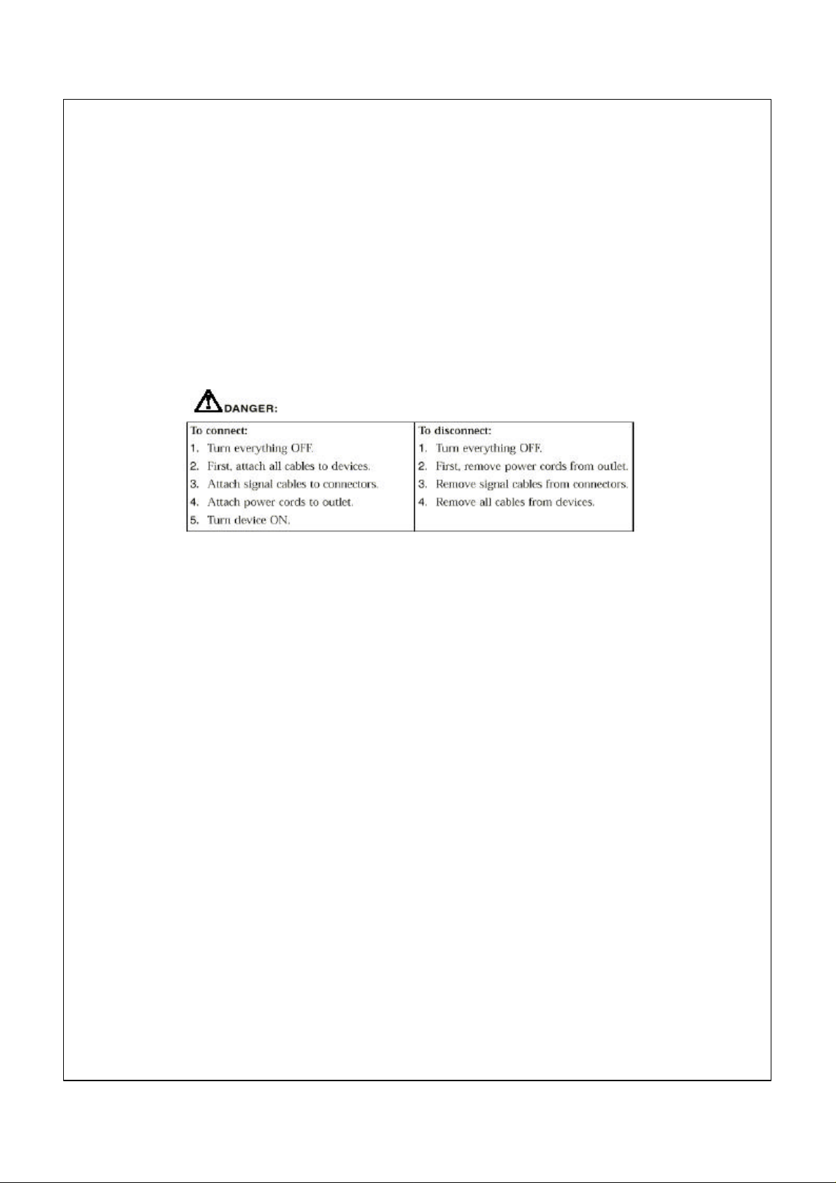
Safety information
Electrical current from power, telephone, and communication cables is
hazardous. To avoid shock hazard, connect and disconnect cables as shown
below when installing, moving or opening the covers of this product or attached
devices. The power cord must be used with a properly grounded outlet.
NOTE:
In the U.K., by law, the telephone cable must be connected after the power
cord. When disconnecting, the power cord must be disconnected after the
telephone line cable.
vi
Page 7
Modem Safety Information
To reduce the risk of fire, electrical shock, or injury when using telephone
equipment, always follow basic safety precautions, such as:
• Never install telephone wiring during a lightning storm.
• Never install telephone jacks in wet locations unless the jack is
specifically designed for wet locations.
• Never touch uninsulated telephone wires or terminals unless the
telephone line has been disconnected at the network interface.
• Use caution when installing or modifying telephone lines.
• Avoid using a telephone (other than a cordless type) during an
electrical storm. There may be a remote risk of electric shock from
lightning.do not use the telephone to report a gas leak in the vicinity of the
leak.
To avoid a shock hazard, do not connect or disconnect any cables
or perform installation, maintenance, or reconfiguration of this
product during an electrical storm.
vii
Page 8
Laser compliance statement Some IBM Personal Computer models are equipped from the factory with a
CD-ROM drive or a DVD-ROM drive. CD-ROM drives and DVD-ROM
drives are also sold separately as options. CD-ROM drives and DVD-ROM
drives are laser products. These drives are certified in the U.S. to conform
to the requirements of the Department of Health and Human Services 21
Code of Federal Regulations (DHHS 21 CFR) Subchapter J for Class 1 laser
products. Elsewhere, these drives are certified to conform to the
requirements of the International Electrotechnical Commission (IEC) 825
and CENELEC EN 60 825 for Class 1 laser products.
When a CD-ROM drive or a DVD-ROM drive is installed, note the
following.
CAUTION:
Use of controls or adjustments or performance of procedures other than
those specified herein might result in hazardous radiation exposure.
Removing the covers of the CD-ROM drive or DVD-ROM drive could result
in exposure to hazardous laser radiation. There are no serviceable parts
inside the CD-ROM drive or DVD-ROM drive. Do not remove the drive
covers.
Some CD-ROM drives and DVD-ROM drives contain an embedded Class
3A or Class 3B laser diode. Note the following.
Danger!
Laser radiation when open. Do not stare into the beam, do not view directly
with optical instruments, and avoid direct exposure to the beam.
viii
Page 9

Lithium battery notice
CAUTION:
Danger of explosion if battery is incorrectly replaced.
When replacing the battery, use only IBM Part Number 33F8354 or an
equivalent type battery recommended by the manufacturer. The battery
contains lithium and can explode if not properly used, handled, or
disposed of.
Do not:
• Throw or immerse into water
• Heat to more than 100°C (212°F)
• Repair or disassemble
•
Dispose of the battery as required by local ordinances or regulations. About this book
This book will help you become familiar with your IBM Personal
Computer and its features. It describes how to set up, operate, maintain,
and install options in your computer. In the unlikely event you experience
problems, you will find helpful troubleshooting information and
instructions for obtaining service in this book.
Related information
Following is a description of the documentation that contains additional
information about your computer. These documents are available in
Adobe PDF format at http://www.ibm.com/pc/support on the World
Wide Web.
• Hardware Maintenance Manual
This publication contains information for trained service technicians. It
can be found at http://www.ibm.com/pc/support/us/ on the World
Wide Web.
Type the machine type/model number into the Quick Path field and
click Go. Click Online publications and then click Hardware
Maintenance Manuals.
This manual can also be ordered from IBM. To purchase a copy, refer
to Chapter 7, “Getting help, service, and additional information”
on page 67.
ix
Page 10

Page 11
CChhaapptteerr 11.. IIBBMM PPCC 330000 oovveerrvviieew
Thank you for selecting an IBM PC300. Your computer incorporates
many of the latest advances in computer technology and can be upgraded
as your needs change.
This section provides an overview of the computer features, preinstalled
software, and specifications.
Identifying your computer
In most instances, the best way to identify your computer is by the machine
type/model number. The machine type/model number indicates the
various features of the computer, such as the type of microprocessor and
the number of bays. You can find this number on the small label on the
front of your computer. An example of a machine type/model number is
2169-55G.
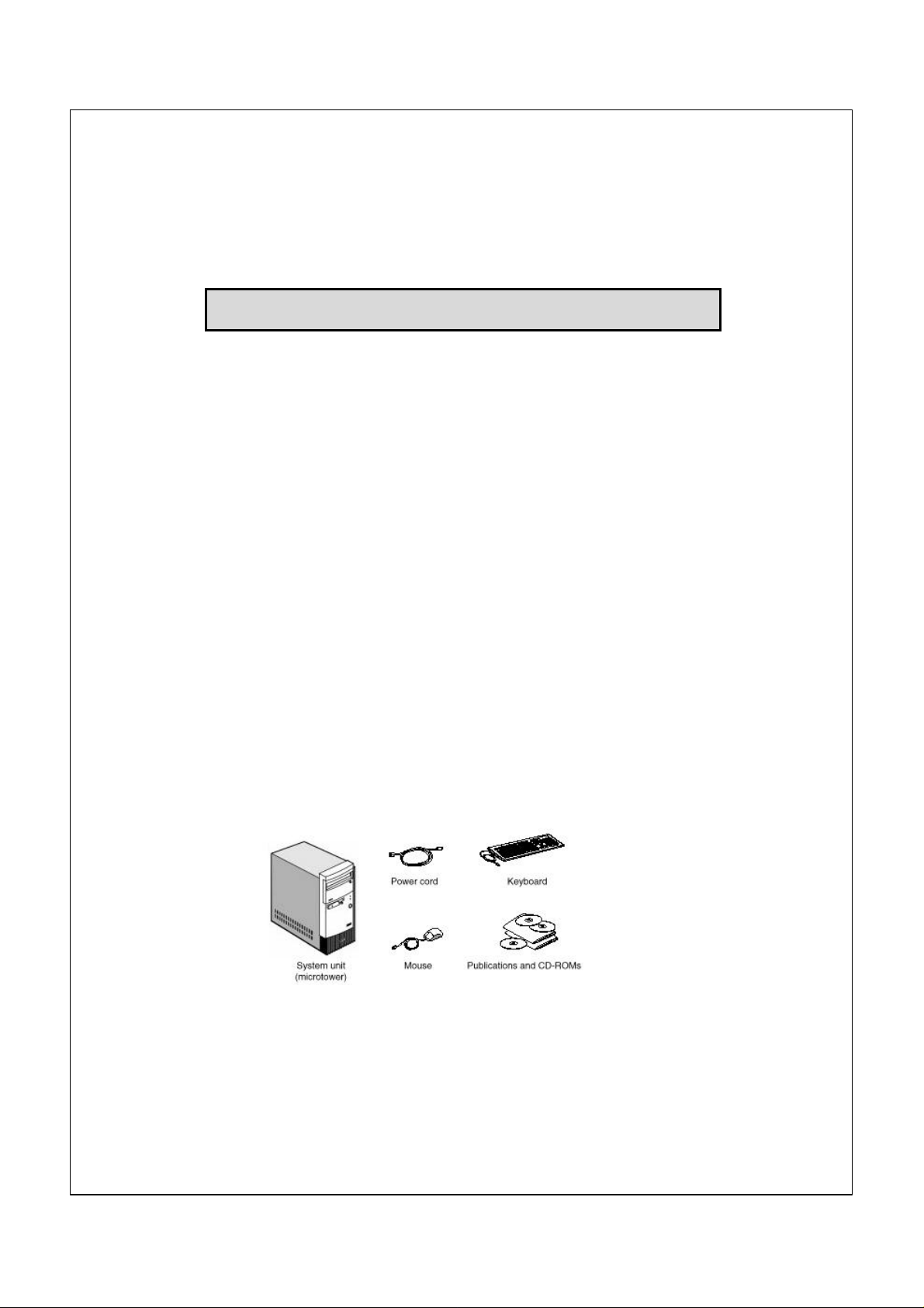
Components included with all models
w
1
Page 12

System Summary
Processor
(Some models)
Clocks
• Intel Celeron processor with integrated 128KB level two cache
• Intel Pentium III processor with integrated 256KB level two cache
• 66MHz clock to Celeron processor front side bus
• 100MHz clock to Pentium III processor front side bus
• 100MHz clocks to SDRAM modules on DIMM sockets
• 33MHz clocks to PCI slots
Chipset
• Intel 810 chipset consisting of
FW82810 Graphics and memory Controller Hub
FW82801AA I/O Controller Hub
N82802AB Firmware Hub
• ITE IT8870F low pin count (LCP) interface super I/O controller
Memory
• Two sockets for 168-pin, 3.3v dual inline memory module (DIMM)
• 100MHz, non-parity, unbuffered SDRAM module
• With 32MB (base model)
•256MB maximum in the system
Video Subsystem
• Integtrated in Intel 810 chipset
• 640 x 480, 800 x 600, 1024 x 768 resolution with 24-bit colors
Storage Devices
• 3.5-inch FDD x 1 for 720KB and 1.44MB media
• 3.5-inch HDD x 1 with minimum 5GB hard disk
• Two open bays for optional CD-ROM etc. (CD standard on some
models)
Audio Subsystem
• On board audio
Network Interface § None on the mother board.
§ 56K v.90 modem on some models
§ Headers for WOL and WOM are provided on the system board
Expansion Slots
External Interface
BIOS
Keyboard/Mouse
Physical Size
Power
Consumption
Power Supply
Preload OS
• Two PCI 2.1 slots
• Serial port x 1 with D-sub 9-pin connector
• Parallel port x 1 with D-sub 25-pin connector
• USB port x 2
• Video port x 1 with D-sub 15-pin connector
• Keyboard port x 1 with PS/2 mini-DIN connector
• Mouse port x 1 with PS/2 mini-DIN connector
• Line In, Line out
• Midi port
• AWARD BIOS in 4Mbit flash memory
• MS PC99 complied
• IBM 105-key/Two button
• 380(H) x 196(W) x 360(D) 7.6Kg
• Maximum
• Nominal
• Sleep
• Soft Off
• 100-127V AC 5A / 200-240V AC 3A
• Windows 98 SE
62 watts
35 watts
27 watts
3 watts
2
Page 13

Ambient Air
• Power On
• Power Off
10 ~ 35 degree C 8 ~ 80 %
10 ~ 43 degree C 8 ~ 80 %
3
Page 14
CChhaapptteerr 22.. SSeettttiinngg uupp yyoouurr ccoommppuutteer
Before you begin, be sure to read “Safety Information” on page vi. Use these
instructions to set up your computer.
r
Selecting a location for your computer
Make sure you have an adequate number of properly grounded electrical
outlets for all devices. Select a location for the computer where it will remain
dry. Leave about 50 mm (2 in.) of space around the computer for proper air
circulation.
Arranging your workspace
Arrange both the equipment and your work area to suit you. Light sources, air
circulation, and the location of electrical outlets can affect how you arrange
your workspace.
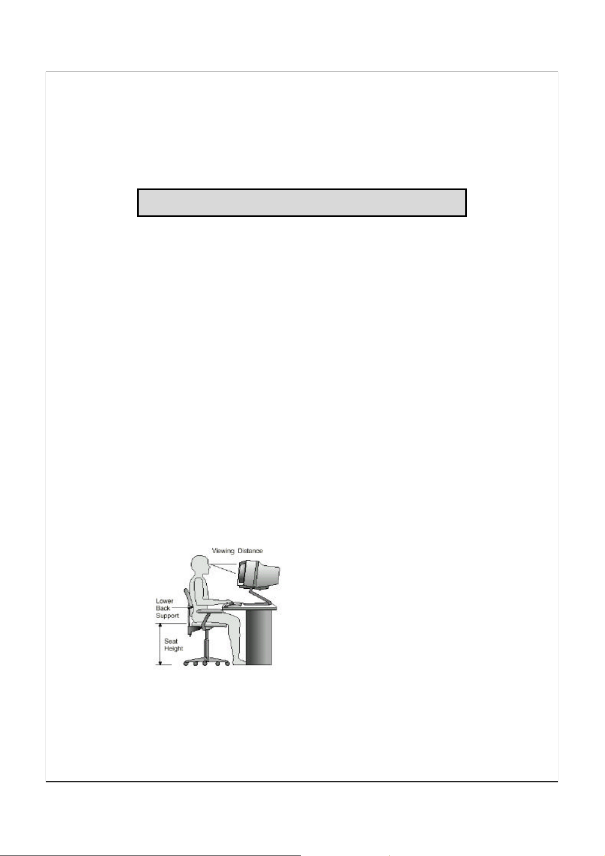
Comfort
The following guidelines will help you decide what working position suits you
best. Choose a chair to reduce fatigue from sitting in the same position for long
periods. The backrest and seat should adjust independently and provide good
support. The seat should have a curved front to relieve pressure on the thighs.
Adjust the seat so that your thighs are parallel to the floor and your feet are
either flat on the floor, or on a footrest.
When using the keyboard, keep your forearms parallel to the floor and your
wrists in a neutral, comfortable position. Try to keep a light touch on the
keyboard, and your hands and fingers relaxed. Change the angle of the
keyboard for maximum comfort by adjusting the position of the keyboard feet.
4
Page 15

Adjust the monitor so that the top of the screen is at, or slightly below, eye
level. Place the monitor at a comfortable viewing distance, usually 51 to 61 cm
(20 to 24 in.), and position it so that you can view it without having to twist
your body.
Glare and lighting
Position the monitor to minimize glare and reflections from overhead lights,
windows, and other light sources. Place the monitor at right angles to light
sources whenever possible. Reduce overhead lighting, if necessary, by turning
off lights or using lower wattage bulbs. If you install the monitor near a
window, use curtains or blinds to block the sunlight. You might have to adjust
the Brightness and Contrast controls on the monitor as the lighting changes
throughout the day.
Where it is impossible to avoid reflections or to adjust the lighting, place an
antiglare filter over the screen. However, these filters might affect the clarity of
the screen image; try them only after you have exhausted other methods of
reducing glare.
Dust compounds problems associated with glare. Clean your monitor screen
periodically using a soft cloth moistened with a nonabrasive, liquid glass
cleaner.
Air circulation
Your computer and monitor produce heat. The computer fan pulls in fresh air
and forces out hot air. The monitor lets hot air escape through vents. Blocking
the air vents can cause overheating, possibly resulting in malfunction or
damage. Place the computer and monitor so that nothing blocks the air vents;
usually 51 mm (2 in.) of air space is sufficient. Also, make sure the vented air
is not blowing on someone else.
Electrical outlets and cable lengths
The location of electrical outlets and the length of device power cords and
cables might determine the final placement of your computer.
When arranging your workspace:
Avoid the use of extension cords. Whenever possible, plug the computer
power cord directly into an electrical outlet.
Keep power cords and cables neatly routed away from walkways and other
areas where they might be accidentally dislodged.For more information about
power cords, see “Power cord notice” on page 81.
5
Page 16
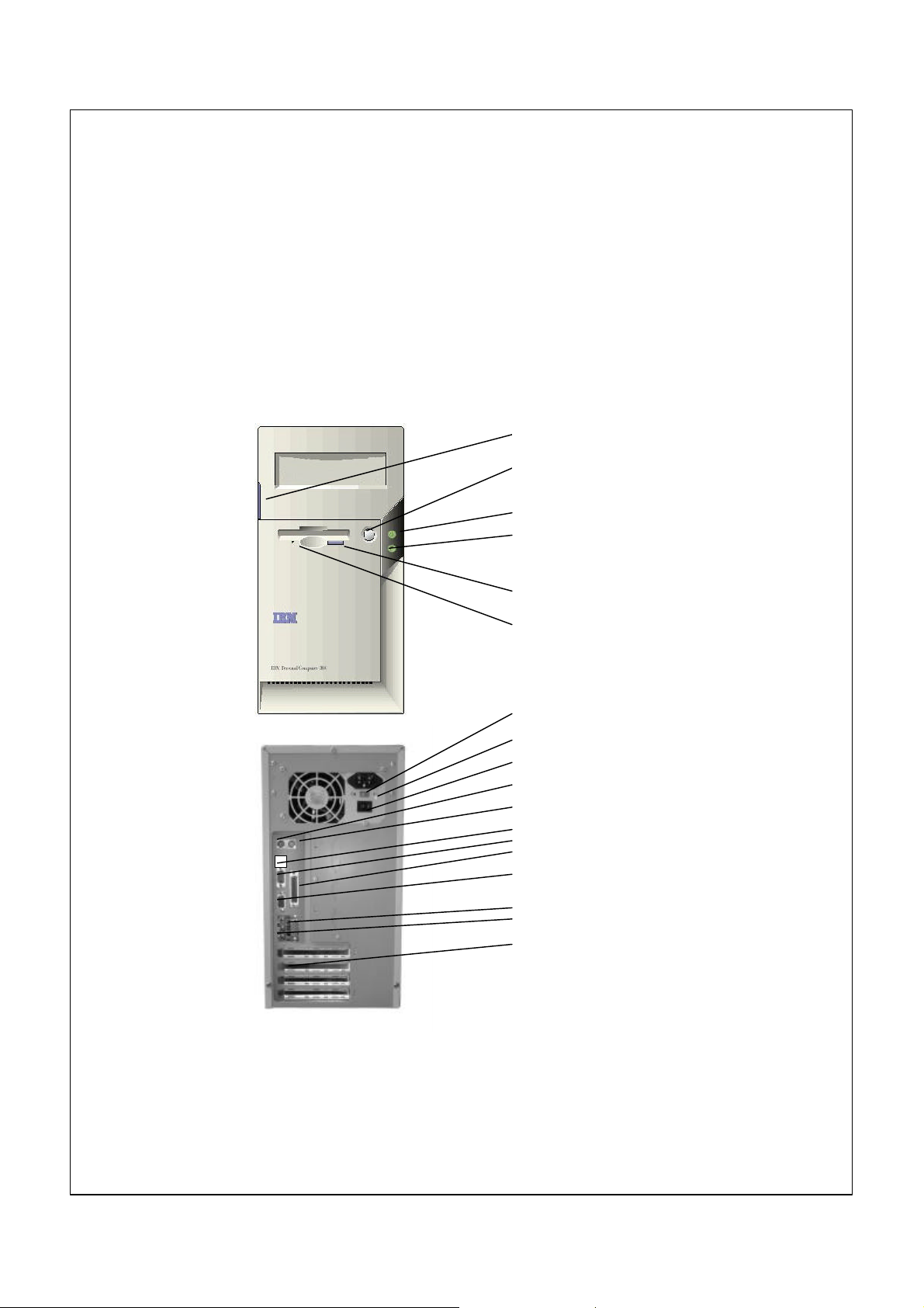
Switches, Indicators and Connectors
Storage Bay Knob
Power-On
Power-On Light
Hard-Disk Drive Light
Diskette Eject Button
Diskette Drive Light
Power Connector
Voltage Selection Switch
Power Switch
Keyboard
Mouse
USB PORT
Serial
Parallel
SVGA Monitor
Midi Port
Line in/out
PCI Adapter slot
6
Page 17
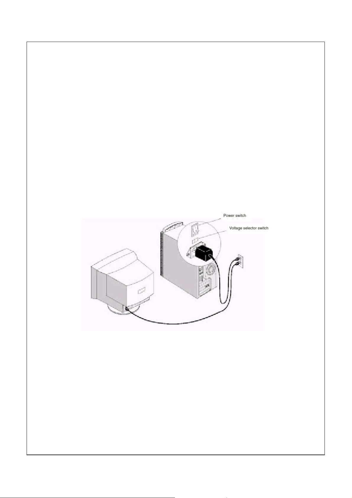
Connect Power cords
The voltage selector switch should be preset for your area; however, contact
your local power company if you are uncertain of the voltage for your area.
• If the voltage supply range in your area is 100-127V, set the voltage selector
switch so you can see 115V or 115.
• If the voltage supply range in your area is 200-230V, set the voltage selector
switch so you can see 230V or 230.
Connect the power cords to the computer and monitor first, and then connect
the power cords to the electrical outlets. For clarity, only the power cords are
shown in this picture.
Note: If your computer has a power switch on the back of the computer, press
it to the On position (1=ON).
7
Page 18

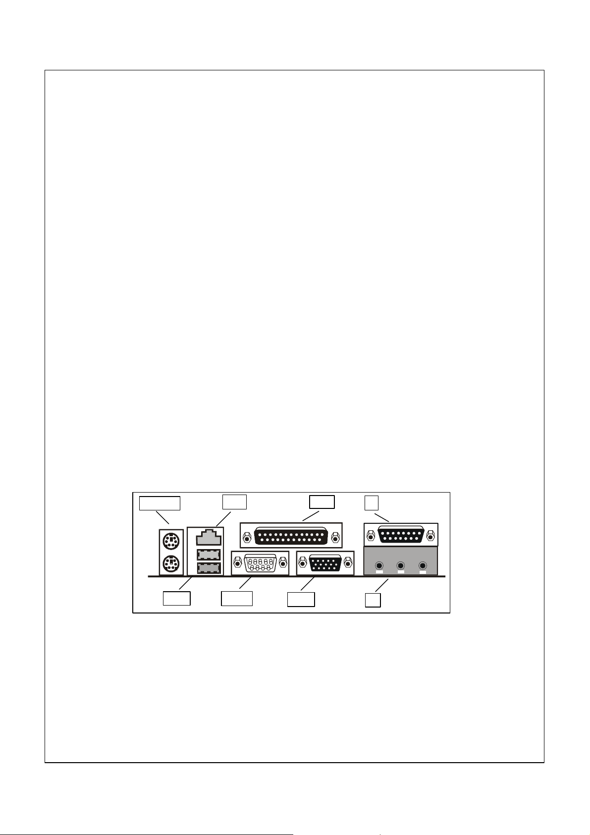
Connecting the system components
Most cable connectors are color-coded to match the location at the back of the
system unit where you connect the cable.
Read “Safety information” on page vi in the User Guide to learn about
connecting cables.
1. PS2KBM is a stack of two PS/2 mini-DIN ports. The upper port can be
used by a PS/2 mouse or pointing device. The lower port can be used by a
PS/2 keyboard.
2. LAN is an RJ45 connector. You can plug an ethernet networking cable into
this connector to join your system to an Local Area Network (LAN).
NOTE: Only applies to LAN models
3. LPT1 is a parallel port that can be used by printers or other parallel
communications devices. The system identifies the parallel port as LPT1.
4. The upper 15-pin port JS is a game/MIDI port. You can use this port to
connect a joystick or a MIDI device to your system
5. The lower part of JS is three audio jacks. The left side jack is for a stereo
line out signal. The middle jack is for a stereo line in signal. The right side
jack is for a microphone.
6. VGA1 is the connector for a display monitor. Plug the data cable from the
monitor into VGA1.
7. COM1 is a serial port that can be used by serial devices such as a mouse,
a fax/modem and so on. This serial port is identified by the system as
COM1/3.
8. USB1 is a stack of two Universal Serial Bus ports. Use these ports to
connect to USB devices.
8
Page 19
External Connector Color Coding
To help identify the external connectors, many connectors now use
standard colors as shown in the table below.
Connector Color
Analog VGA Blue
Audio line in Light blue
Audio line out Lime
Digital monitor / flat panel White
IEEE 1394 Grey
Microphone Pink
MIDI/Game Gold
Parallel Burgundy
PS/2 compatible keyboard Purple
PS/2 compatible mouse Green
Serial Teal or Turquoise
Speaker out / subwoofer Orange
Right-to-left speaker Brown
USB Black
Video out Yellow
SCSI, network, telephone, modem, and so on None
NOTE: 1)Only LAN models have a LAN socket
2)Some connectors listed are not available on all models
PS2KBM
USB1
LAN
COM1
VGA1
LPT1
JS
JS
9
Page 20

Turning on power
Turn on the monitor and other external devices first. Turn on the computer.
When the self-test is done, the IBM® logo screen disappears. If your computer
has preinstalled software, the software installation program begins.
If you experience any problems during startup, refer to Chapter 6
“Troubleshooting” on page 51 and Chapter 7 “Getting help, service, and
additional information” on page 67.
Finishing the software installation
After you start the computer for the first time, follow the instructions on the
screen to complete the software installation. If you do not complete the
software installation the first time the computer is turned on, unexpected
results might occur. For detailed information about the software installation,
see the online About Your Software publication.
If you use Microsoft® Windows® 98 Second Edition. Your computer is ready to
use after the software installation.
Accessing reference materials
After you start your computer and finish the operating system installation,
become familiar with the reference materials. You might want to print a
portion of your online publications for future reference.
To access the online User Guide double click Access IBM on your desktop.
Click Get help –View documentation.
For further information about reference publications, see
“Chapter 7. Getting help, service, and additional information” on page 67.
10
Page 21

CChhaapptteerr 33:: OOppeerraattiinngg aanndd ccaarriinngg ffoor
r
yyoouurr CCoommppuutteer
This chapter provides information to help you in the day-to-day use and care
of your computer.
r
Starting your computer
See “Switches Indicators and Connectors” on page 6 for an illustration
indicating the location of the power buttons on your computer. If your
computer has a power switch on the back, ensure this is
set to position I = On.
What you see and hear when you start up your computer depends on the
startup settings selected in the Configuration/Setup Utility program.
Note: Other selections also might change what is displayed when the
computer starts up.
When you turn on your computer, you are prompted with the following
options:
Press TAB to show POST screen, DEL to enter SETUP
Note: This prompt appears when you first turn on your computer and is gone
very quickly.
For instructions to enter the Configuration/Setup Utility program, see
page 18.
Changing monitor settings
To get the best possible image on your screen and to reduce flicker, you might
need to reset the resolution and refresh rate of your monitor. You can view and
change monitor settings through your operating system using the instructions
provided in the README files on the Software Selections CD that comes with
your computer. Refer to your operating system documentation for further
information on monitor settings.
Attention
Before you change any monitor settings, be sure to review the
information that comes with your monitor. Using a resolution or refresh
rate that is not supported by your monitor might cause the screen to
become unreadable and could damage the monitor. The information that
11
Page 22

comes with your monitor usually includes the resolutions and refresh
rates that the monitor supports. If you need additional information,
contact the manufacturer of the monitor.
To minimize screen flicker and jitter, set your monitor for the highest
noninterlaced refresh rate that the monitor supports. If your monitor complies
with the VESA Display Data Channel (DDC) standard, it is probably already
set to the highest refresh rate that the monitor and video controller can
support. If you are not sure if your monitor is DDC-compliant, refer to the
documentation provided with the monitor.
Using audio features
Your computer comes with an integrated audio controller to which external
speakers can be connected
Procedures for recording and playing back sound vary by operating system.
Refer to your operating system documentation for information and instructions.
The audio connectors in your computer are 3.5 mm (1/8-in.) mini-jacks. A
description of the connectors follows. (For the location of the connectors, refer
to “External connector color coding” on page 9.)
Line/Headphone Out:
This jack is used to send audio signals from the computer to external devices,
such as stereo-powered speakers with built-in amplifiers, headphones,
multimedia keyboards, or the Audio Line-In jack on a stereo system.
Audio Line In:
This jack is used to accept audio signals from external devices, such as line
output from a stereo or television system, or a musical instrument, into the
computer sound system.
Microphone:
This jack is used to connect a microphone to your computer when you want to
record voice or other sounds on the hard disk.
Note: If you experience interference or speaker feedback while recording, try
reducing the microphone recording volume (gain).
Joystick/MIDI:
This port is used to connect a joystick for playing games or a MIDI device to
interface with digital musical and sound production equipment.
12
Page 23

Using diskettes
You can use 3.5-inch diskettes in the diskette drive of your computer.
The information that follows will help you use 3.5-inch diskettes.
Handling and storing diskettes
Inside the protective diskette case is a flexible disk with a magnetic coating.
This disk can be damaged by heat, dust, a magnetic field, or even a
fingerprint. Use the following guidelines when handling and storing diskettes:
– Data is stored on the magnetic surface of the diskette. This surface is
protected by a plastic cover. If the cover is damaged, do not use the
diskette. A damaged diskette might damage the diskette drive.
– A protective slide on the top of a 3.5-inch diskette covers part of the
magnetic surface. The diskette drive moves this slide to read data from or
write data to the diskette. Do not move this slide because fingerprints and
dust can cause loss of data.
– Never touch the magnetic disk itself.
– Keep diskettes away from magnets or devices that create a strong
magnetic field, such as electric motors and generators. Diskettes are
sensitive to magnets found in television sets, telephones, stereo speakers,
and other such items. A magnetic field can erase the data on your
diskettes. Do not set diskettes on the monitor or use magnets to attach
notes to your computer.
– Do not store diskettes at high temperatures, low temperatures, or in direct
sunlight. Temperatures ranging from 4° to 53°C (39° to 127°F) are
acceptable for 3.5-inch diskettes. Keep diskettes away from heat. The
plastic outer covering might warp, damaging the diskette.
Inserting and removing diskettes To insert a 3.5-inch diskette, hold the diskette with the label facing up and
insert the end with the protective slide first. Push the diskette into the diskette
drive until the diskette clicks into place.
To remove the diskette, press the eject button and slide the diskette out of the
drive. Do not remove the diskette while the in-use light is on.
13
Page 24

Using a CD-ROM drive Some models have a preinstalled CD-ROM drive. CD-ROM drives can play
back or read from a CD, but cannot write information to it. CD-ROM drives
use industry standard, 12 cm (4.75-inch) CDs.
Follow these guidelines when using a CD-ROM drive:
Do not place the drive where there is:
– High temperature
– High humidity
– Excessive dust
– Excessive vibration or sudden shock
– An inclined surface
– Direct sunlight
– Do not insert any object other than a CD into the drive.
– Before moving the computer, remove the CD from the drive.
Handling a CD When handling a CD, follow these guidelines:
– Hold the CD by its edges. Do not touch the surface of the side that is not
labeled.
– To remove dust or fingerprints, wipe the CD with a clean, soft cloth from
the center to the outside. Wiping the CD in a circular direction might cause
loss of data.
– Do not write or stick paper on the CD.
– Do not scratch or mark the CD.
– Do not place or store the CD in direct sunlight.
– Do not use benzene, thinners, or other cleaners to clean the disk.
– Do not drop or bend the CD.
Loading a CD To load a CD into a CD-ROM drive:
1. Press the Eject/Load button. The tray slides out of the drive. (Do not
manually force the tray open.)
Note: If you have a small form factor desktop computer, the CD-ROM
drive disk tray slides partway out of the drive. Manually pull the
tray the rest of the way out.
2. Place the CD in the tray with the label facing up.
Note: If you have a small form factor desktop computer, press the disk
down until it clicks into place and is held by the spring-loaded
holders.
14
Page 25

3. Close the tray by pressing the Eject/Load button or by gently pushing the
tray forward. When the tray is closed, the indicator light on the front of the
drive will activate to indicate that the drive is in use.
4. To eject the CD, press the Eject/Load button. When the tray slides out,
carefully remove the disk.
5. Close the tray by pressing the Eject/Load button or by gently pushing the
tray forward.
Note: If the tray does not slide out of the drive when you press the Eject/Load
button, insert the pointed end of a large paper clip into the
emergency-eject hole located on the front of the CD-ROM drive.
Updating system programs System programs are the basic layer of software built into your computer. They
include the power-on self-test (POST), the basic input/output system (BIOS)
code, and the Configuration/Setup Utility program. POST is a set of tests and
procedures that is performed each time you turn on your computer. BIOS is a
layer of software that translates instructions from other layers of software into
electrical signals that the computer hardware can understand. You can use the
Configuration/Setup Utility program to view and change the configuration and
setup of your computer.
Your computer system board has a module called electrically erasable
programmable read-only memory (EEPROM, also referred to as flash
memory). You can easily update POST, BIOS, and the Configuration/Setup
Utility program by starting your computer using a flash update diskette.
IBM might make changes and enhancements to the system programs. When
updates are released, they are available as downloadable files on the World
Wide Web (see “Chapter 7. Getting help, service, and additional information”
on page 67). Instructions for using the system programs updates are available
in a README file included in the update files.
Shutting down
When you are ready to turn off your computer, follow the shutdown procedure
for your operating system to prevent the loss of unsaved data or damage to
your software programs. See your operating system documentation for
instructions.
15
Page 26

Taking care of your computer This section provides guidelines for the proper handling and care of your
computer.
Basics
Here are some basic points about keeping your computer functioning properly:
• Keep your computer in a clean, dry environment. Make sure it rests on a
flat, sturdy surface.
• Do not place items on top of the monitor or cover any vents in the monitor
or computer. These vents provide air flow to keep your computer from
overheating.
• Keep food and drinks away from all parts of your computer. Food particles
and spills might make the keyboard and mouse sticky and unusable.
• Do not get the power switches or other controls wet. Moisture can damage
these parts and cause an electrical hazard.
• Always disconnect a power cord by grasping the plug, not the cord.
Cleaning your computer
It is a good practice to clean your computer periodically to protect the surfaces
and ensure trouble-free operation.
CAUTION:
Be sure to turn off the computer and monitor power switches before
cleaning the computer and monitor screen.
Computer and keyboard
Use only mild cleaning solutions and a damp cloth to clean the painted
surfaces of the computer.
Monitor screen
Do not use abrasive cleaners when cleaning the surface of the monitor screen.
The screen surface is easily scratched, so avoid touching it with pens, pencil
points, and erasers. To clean the screen surface, wipe it gently with a soft, dry
cloth, or blow on the screen to remove grit and other loose particles. Then use a
soft cloth moistened with a nonabrasive liquid glass cleaner.
Mouse
If the pointer on the screen does not move smoothly with the mouse, you
might need to clean the mouse. To clean your mouse:
1. Turn off the computer.
2. Disconnect the mouse cable from the computer.
3. Turn the mouse upside down. Unlock the retainer on the bottom of the
16
Page 27
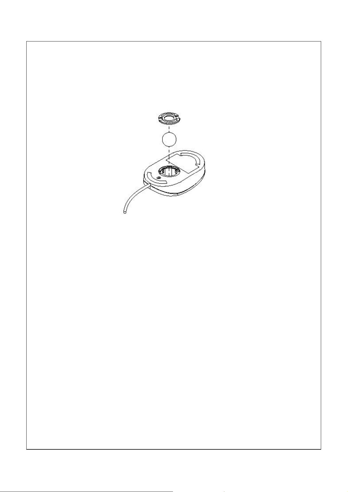
mouse by moving it in the direction indicated by the arrow on the retainer.
4. Turn the mouse right-side up, and the retainer and ball will drop out.
5. Wash the ball in warm, soapy water and dry it well.
6. Using a damp cloth, wipe the outside of the mouse and the retainer. Be
sure to wipe the rollers inside the mouse.
7. Insert the ball and retainer. Lock the retainer by moving it in the opposite
direction of the arrow.
8. Reconnect the mouse cable to the computer.
Moving your computer
Take the following precautions before moving your computer.
1. Back up all files and data from the hard disk.
Operating systems can vary in the way they perform backup procedures.
Refer to your operating system documentation for information about
software backup.
2. Remove all media (diskettes, compact discs, tapes, and so on) from the
drives.
3. Turn off the computer and all attached devices. Your hard disk drive
automatically parks the read/write heads in a nondata area. This process
prevents damage to the hard disk.
4. Unplug the power cords from electrical outlets.
5. Note where you have attached your cables to the rear of the computer; then
remove them.
6. If you saved the original shipping cartons and packing materials, use them
to pack the units. If you are using different cartons, cushion the computer
components to avoid damage.
17
Page 28

CChhaapptteerr 44 ::UUssiinngg tthhe
e
CCoonnffiigguurraattiioonn//SSeettuupp UUttiilliitty
This chapter explains how to use and modify the BIOS setup utility that is
stored on the System Board. The setup utility stores data about the System
Board components and the configuration of devices that are connected to it.
This information is used to test and initialize components at start-up time and to
make sure everything runs properly when the system is operating.
The setup utility is installed with a set of default values. You will probably have
to make changes to the setup utility whenever you add new components to your
system such as new disk drives. We recommend that you do not change some
of the timing values in the setup, as this can have an adverse affect on the
operation of your computer.
y
Starting the Setup Utility
You can only start the setup utility shortly after the computer has been turned
on. A prompt appears on the computer display which says “Press DEL to run
Setup”. When you see this prompt, press the Delete key, and the system will
start the setup utility and display the main menu of the utility.
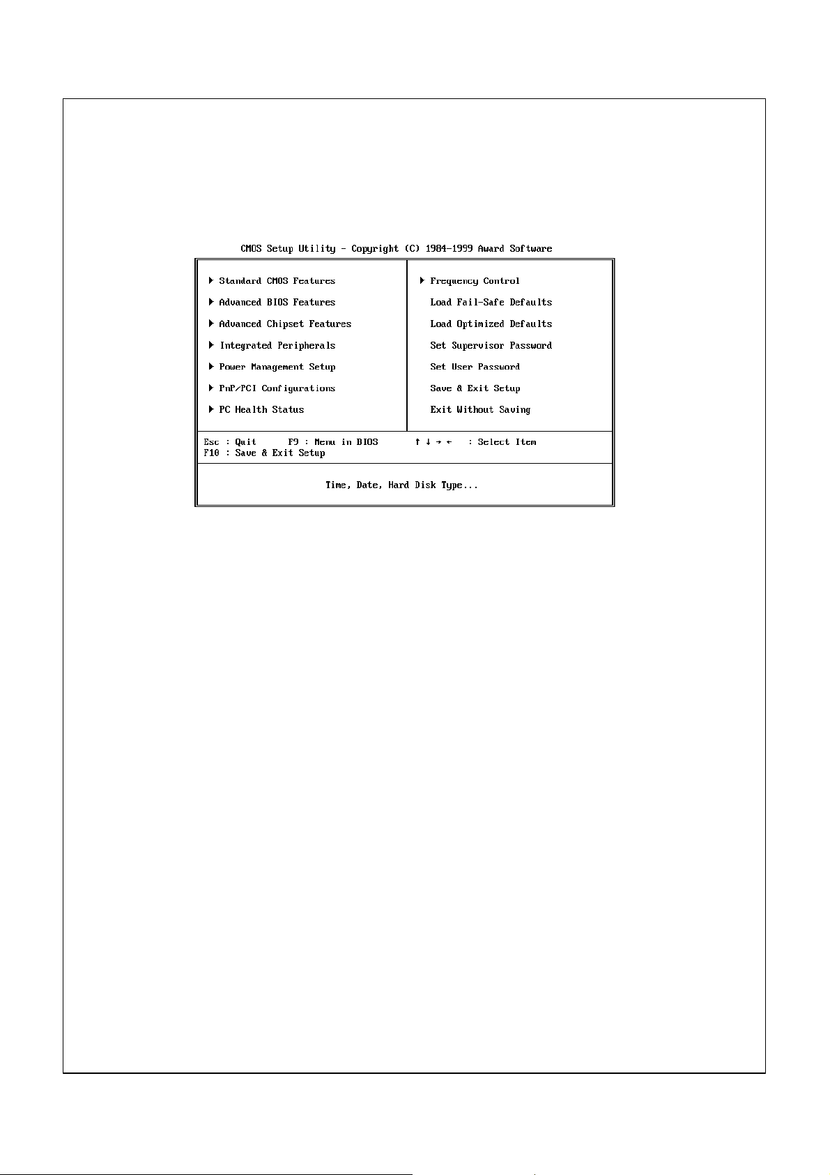
Using the Setup Utility
When you start setup, the main menu appears. The main menu of the setup
utility shows a list of the options that are available. A highlight shows which
option is currently selected. You can use the cursor arrow keys to move the
highlight to other options. When an option is highlighted, you can execute the
option by pressing the Enter key.
Some options lead to dialog boxes which ask you verify that that you wish to
execute that option. You usually answer these dialogs by typing Y for yes and N
for no. Some options lead to dialog boxes which ask for more information.
Setting passwords have this kind of dialog box.
18
Page 29
Some options (marked with a triangle) lead to tables of items that usually have
a value on the right side. The value of the first item is highlighted, and you can
use the cursor arrow keys to select any of the other values in the table of items.
When an item is highlighted, you can change the value by pressing the PageUp
or PageDown keys to scroll through the available values.
When you are in the main menu, you can exit the utility by pressing the Escape
key. You can save the current selections and exit the utility by pressing the F10
key. When you are in one of the options that displays a dialog box, you can
return to the main menu by pressing the Escape key.
When you are in an option that displays a table of items, you can return to the
main menu by pressing the Escape key. For some items, you can display a
help message by pressing the F2 key. You can display a general help screen by
pressing F1. Press F5 to discard any changes you have made and return all
items to the value that they held when the setup utility was started. Press F6 to
load the displayed items with a standard list of fail-safe values. Press F7 to load
the displayed items with a list of optimized default values.
Note: Screenshots are for reference only and may not reflect your machines
specification.
19
Page 30

Standard CMOS Features Option
This option displays a table of items which defines basic information about your
system.
10268MB
Date and Time
The Date and Time items show the current date and time held by your
computer. If you are running a Windows OS, these items are automatically
updated whenever you make changes to the Windows Date and Time
Properties utility.
IDE Devices Defaults: None
Your computer has two IDE channels (Primary and Secondary) and each
channel can be installed with one or two devices (Master and Slave). Use these
items to configure each device on the IDE channel. Press Enter to display the
IDE sub-menu.
20
Page 31

10263
19885
16
0
19884
63
IDE HDD Auto-Detection
Press Enter while this item is highlighted if you want the setup utility to
automatically detect and configure a hard disk drive on the IDE channel.
IDE Primary/Secondary Master/Slave
If you leave this item at Auto, the system will automatically detect and configure
any IDE devices it finds. If it fails to find a hard disk, change the value to
Manual and then manually configure the drive be entering the characteristics of
the drive in the items below (Capacity, Cylinder, Head, Precomp, etc.), If you
have no device installed change the value to None.
Access Mode
This items defines some special ways that can be used to access IDE hard
disks such as LBA (Large Block Addressing). Leave this value at Auto and the
system will automatically decide the fastest way to access the hard disk drive.
Press Esc to close the IDE device sub-menu and return to the Standard CMOS
Features page.
Drive A and Drive B Default: 1.44M, 3.5 in., None
These items define the characteristics of any diskette drive attached to the
system. You can connect one or two diskette drives.
Floppy 3 Mode Support Default: Disabled
Floppy 3 mode refers to a 3.5” diskette with a capacity of 1.2 MB. Floppy 3
mode is sometimes used in Japan.
21
Page 32

Video Default: EGA/VGA
This item defines the video mode of the system. This System Board has a builtin VGA graphics system so you must leave this item at the default value.
Halt On Default: All But Keyboard
This item defines the operation of the system POST (Power On Self Test)
routine. You can use this item to select which kind of errors in the POST are
sufficient to halt the system.
Base Memory, Extended Memory, Total Memory
These items are automatically detected by the system at start up time.
Advanced BIOS Features Setup Option
This option displays a table of items which defines more advanced information
about your system. You can make modifications to most of these items without
introducing fatal errors to your system. Note that the page has a scroll-bar to
scroll down to more items.
Anti-Virus Protection Disabled
Machine Type IBM 2169
System Board ID i810-ITE8712
System BIOS version 6.00 PG1.2g
CPU Internal Cache Enabled
External Cache Enabled
CPU L2 Cache ECC checking Enabled
Processor Number Feature Enabled
Quick Power On Self Test Enabled
First Boot Device Floppy
Seconf Boot Device CD-ROM
Third Boot Device HDD-0
Boot Other Device Enabled
Swap Floppy Device Disabled
Boot Up Floppy Seek Enabled
Boot Up NumLock Status On
GateAZ0 Option Fast
PrimWare Write Protection Disabled
Typematic Rate Setting Disabled
*Typematic Dealy(Chars/Sec) 6
Anti-Virus Protection Default: Disabled
When this item is enabled it provides some protection against viruses which try
to write to the boot sector and partition table of your hard disk drive. This item
is Disabled as a default. You need to disable it so that you can install an
operating system. We recommend that you enable Anti-Virus Protection as
soon as you have installed your disk with an OS.
22
Page 33

CPU Internal Cache Default: Enabled
All the processors that can be installed in this System Board use internal (level
1) cache memory to improve performance. Leave this item at the default value
Enabled for better performance.
External Cache Default: Enabled
The processors that can be installed in this system use an integrated L2 cache
memory to improve performance.
CPU L2 Cache ECC Checking Default: Enabled
This item enables or disables ECC (Error Correction Code) error checking on
the CPU cache memory. We recommend that you leave this item at the default
value.
Quick Power On Self Test Default: Enabled
You can enable this item to shorten the power on testing and have your system
start up a little faster. You might like to enable this item after you are confident
that your system hardware is operating smoothly.
First/Second/Third Boot Device Default: Floppy/CD-ROM/HDD-0
Use these three items to select the priority and order of the devices that your
system will search for an operating system at start-up time.
Boot Other Device Default: Enabled
If you enable this item, the system will search all other possible locations for an
operating system if it fails to find one in the devices specified under the first,
second and third boot devices.
Swap Floppy Drive Default: Disabled
If you have two floppy diskette drives in your system, this item allows you to
swap around the assigned drive letters so that drive A becomes drive B, and
drive B becomes drive A.
Boot Up Floppy Seek Default: Enabled
If this item is enabled, it checks the geometry of the floppy disk drives at startup time. You don’t need to enable this item unless you have a old diskette drive
with 360K capacity.
Boot Up NumLock Status Default: On
This item defines if the keyboard Num Lock key is active when your system is
started.
Gate A20 Option Default: Fast
This item defines how the system handles legacy software that was written for
an earlier generation of processors. Leave this item at the default value.
Firmware Write Protect Default: Disabled
If you enable this item, it protects the firmware (BIOS) from being overwritten.
Disable this item if you plan to flash a new BIOS to the system.
23
Page 34

Typematic Rate Setting Default: Disabled
If this item is enabled, you can use the following two items to set the typematic
rate and the typematic delay settings for your keyboard.
Typematic Rate (Chars/Sec) Default: 6
If the item Typematic Rate Setting is enabled, you can use this item to define
how many characters per second are generated by a held-down key.
Typematic Delay (Msec) Default: 250
If the item Typematic Rate Setting is enabled, you can use this item to define
how many characters per second are generated by a held-down key.
Security Option Default: Setup
If you have installed password protection, this item defines if the password is
required at system start up, or if it is only required when a user tries to enter the
setup utility.
OS Select For DRAM > 64 MB Default: Non-OS2
This item is only required if you have installed more than 64 MB of memory and
you are running the OS/2 operating system. Otherwise, leave this item at the
default Non-OS2.
Report No FDD for WIN 95 Default: Yes
If you are running a system with no floppy drive and using the Windows 95 OS,
select Yes for this item to ensure compatibility with the Windows 95 logo
certification.
24
Page 35

Advanced Chipset Features Option
This option displays a table of items that define critical timing parameters of the
System Board components including the memory, and the system logic.
Generally, you should leave the items on this page at their default values unless
you are very familiar with the technical specifications of your system hardware.
If you change the values incorrectly you may introduce fatal errors or recurring
instability into your system. Note that the page has a scroll-bar to scroll down to
more items.
SDRAM CAS Latency Time Default: 3
SDRAM Cycle Time Tras/Trc Default: 6/8
SDRAM RAS-to-CAS Delay Default: 3
SDRAM RAS Precharge Time Default: 3
These four items set the timing and wait states for SDRAM memory. We
recommend that you leave these items at the default value.
System BIOS Cacheable Default: Enabled
Video BIOS Cacheable Default: Enabled
These items allow the video and/or system to be cached in memory for faster
execution. We recommend that you leave these items at the default value.
Memory Hole at 15M-16M Default: Disabled
This item can be used to reserve memory space for some ISA expansion cards
that require it.
25
Page 36

CPU Latency Timer Default: Disabled
This item sets a timing parameter for CPU access. Since the CPU timing is
determined by the system hardware, leave this item at the default value.
Delayed Transaction Default: Enabled
If the chipset has an embedded 32-bit write buffer to support delay transaction
cycles, you can enable this item to provide compliance with PCI Ver. 2.1
specifications. We recommend that you leave this item at the default value.
On-Chip Video Window Size Default: 64 MB
This item defines the size of the aperture if you use an AGP graphics adapter. It
refers to a section of the PCI memory address range used for graphics
memory. We recommend that you leave this item at the default value.
26
Page 37

Integrated Peripherals Option
This option displays a list of items that defines the operation of some
peripheral components on the system’s input/output ports.
On-Chip Primary PCI IDE Default: Enabled
On-Chip Secondary PCI IDE Default: Enabled
Use these items to enable or disable the PCI IDE channels that are integrated
on this System Board.
IDE Primary Master PIO Default: Auto
IDE Primary Slave PIO Default: Auto
IDE Secondary Master PIO Default: Auto
IDE Secondary Slave PIO Default: Auto
Each IDE channel supports a master device and a slave device. These four
items let you assign which kind of PIO (Programmed Input/Output) is used by
IDE devices. You can choose Auto, to let the system auto detect which PIO
mode is best, or you can install a PIO mode from 0-4.
IDE Primary Master UDMA Default: Auto
IDE Primary Slave UDMA Default: Auto
IDE Secondary Master UDMA Default: Auto
IDE Secondary Slave UDMA Default: Auto
27
Page 38

Each IDE channel supports a master device and a slave device. This
motherboard supports UltraDMA. UltraDMA technology provides faster
access to IDE devices. If you install a device which supports UltraDMA,
change the appropriate item on this list to Auto.
USB Controller Default: Enabled
Use this item to enable the USB ports that are integrated on this System Board.
USB Keyboard Support Default: Disabled
Enable this item if you are using a keyboard connected through the USB Port.
Init Display First Default: PCI Slot
Use this item to define if your graphics adapter is installed in one of the PCI
slots or select Onboard if you have a graphics system integrated on the System
Board.
Onboard PCI Audio Default: Enabled
Your PC has an integrated PCI audio system, use this item to enable or disable
it.
Hardware Reset Default: Enabled
If you enable this item, you can reset the system by pressing a hardware reset
button if you have connected this function to the mainboard.
IDE HDD Block Mode Default: Enabled
Block mode transfers can improve the access to IDE devices. Enable this item
if your IDE devices support block mode transfers.
Onboard FDC Controller Default: Enabled
Use this item to turn on or off the floppy disk controller that is built into this
System Board.
Onboard Serial Port 1 Default: 3F8/IRQ4
This item lets you disable the built-in serial port 1, or enable it by assigning an
I/O address and an Interrupt Request Line (IRQ).
Onboard Serial Port 2 Default: Disable
On some models this item lets you disable the built-in serial port 2, or enable it
by assigning an I/O address and an Interrupt Request Line (IRQ).
UART Mode Select Default: Normal
UR2 Duplex Mode DefaultL Half
This item defines the operation of serial port 2. In the Normal setting, serial port
2 is assigned to the external COM2 connector. If you have installed an optional
infrared port, you must change the setting of this item to one of the Infrared
settings (usually IrDA or FIR). These settings will disable the external COM2
serial port connector and assign the resources to the infrared device. If you
have selected an IR mode, use the following item UR2 Duplex Mode to define if
the IR port is full duplex or half duplex.
28
Page 39

Onboard Parallel Port Default: 378/IRQ7
This item lets you disable the built-in parallel port, or enable it by assigning an
I/O address and an Interrupt Request Line (IRQ).
Parallel Port Mode Default: ECP
ECP Mode Use DMA Default: 3
This item defines the operation of the parallel port. If you are connected to a
parallel device that supports the higher-performance EPP (enhanced parallel
port) or the ECP (extended capabilities port) make the appropriate changes to
this item.
PWRON After PWR-Fail Default: Off
If this item is enabled, the system will automatically resume when power is
restored after an interruption in the power supply.
Game Port Address Default: 201
This item lets you disable the built-in game port, or enable it by assigning an
I/O address.
Midi Port Address Default:330
Midi Port IRQ Default: 10
This item lets you disable the built-in MIDI port, or enable it by assigning an I/O
address. If you enable the MIDI port, use the following item Midi Port IRQ to
assign an Interrupt Request line to the port.
29
Page 40

Power Management Setup Option
This option displays items that let you control the system power
management. Operating systems take care of much of the power
management. This mainboard supports ACPI (advanced configuration
and power interface). The system has various power saving modes
including powering down the hard disk, turning off the video, suspending
to RAM, and a software power down that allows the system to be
automatically resumed by certain events.
Power Management Timeouts
The power-saving modes can be controlled by timeouts. If the system is
inactive for a time, the timeouts begin counting. If the inactivity
continues so that the timeout period elapses, the system enters a powersaving mode. If any item in the list of Reload Global Timer Events is
Enabled, then any activity on that item will reset the timeout counters to
zero.
Wake Up Calls
If the system is suspended, or has been powered down by software, it
can be resumed by a wake up call that is generated by incoming traffic
to a modem, a LAN card, a PCI card, or a fixed alarm on the system
realtime clock,
30
Page 41

ACPI Suspend Type Default: S1 (POS)
Use this item to define how your system suspends. In the default, S1(POS), the
suspend mode is equivalent to a software power down. If you select S3 (STR),
the suspend mode is a suspend to RAM – the system shuts down with the
exception of a refresh current to the system memory.
Power Management Default: Define
This item acts like a master switch for the power-saving modes and hard disk
timeouts. If this item is set to Max Saving, power-saving modes occur after a
short timeout. If this item is set to Min Saving, power-saving modes occur after
a longer timeout. If the item is set to User Define, you can insert your own
timeouts for the power-saving modes.
Video Off Method Default: DPMS
This item defines how the video is powered down to save power. As a default,
this is set to DPMS (display power management software).
Video Off In Suspend Default: Yes
This option defines if the video is powered down when the system is put into
suspend mode.
Suspend Type Default: Stop Grant
If this item is set to the default "Stop Grant", the CPU will go into the Idle Mode.
MODEM Use IRQ Default: 3
If you want an incoming call on a modem to automatically resume the system
from a power-saving mode, use this item to specify the interrupt request line
(IRQ) that is used by the modem. You might have to connect the fax/modem to
a mainboard Wake On Modem connector for this feature to work.
31
Page 42

Suspend Mode Default: Disabled
If you have selected User Define for the Power Management item, you can set
this item to a timeouts from 1 Min to 1 Hour. The system will go into the powersaving suspend mode if the timeout passes without any system activity.
HDD Power Down Default: Disabled
If you have selected User Define for the Power Management item, you can set
this item to a selection of timeouts from 1 to 15 minutes. The hard disk drive
will power down if the selected timeout passes without any activity on the hard
disk.
Soft-Off by PWR-BTTN Default: Delay 4 Seconds
Under ACPI (Advanced Configuration and Power management Interface) you
can create a software power down. In a software power down, the system can
be resumed by Wake Up Alarms. This item lets you install a software power
down that is controlled by the normal power button on your system. If the item
is set to Instant-Off, then the power button causes a software power down. If
the item is set to Delay 4 Sec. Then you have to hold the power button down for
four seconds to cause a software power down.
Wake Up by PCI Card Default: Disabled
If you enable this item, it allows activity on an add-in card in one of the PCI
slots to resume the system from a power-saving mode.
Power On by Ring Default: Disabled
If this item is enabled, it allows the system to resume from a software
powerdown or a power-saving mode whenever there is an incoming call to an
installed fax/modem. You might have to connect the fax/modem to a mainboard
Wake On Modem connector for this feature to work.
Wake Up On LAN Default: Enabled
If this item is enabled, it allows the system to resume from a software
powerdown or a power-saving mode whenever there is an incoming traffic to a
network (LAN) adapter. You might have to connect the LAN card to a
mainboard Wake On LAN connector for this feature to work.
CPU Thermal Limit Default: NA
Board Thermal Limit Default: NA
These two items can be used to set threshold temperatures for the CPU and the
mainboard. If the temperatures are exceeded, the system uses power
management to reduce the temperatures.
CPU Thermal-Throttling Default: 50.0%
This item sets the percentage of time that the CPU is idled if CPU throttling is
initiated by excess heat.
Resume by Alarm Default: Disabled
If this item is Enabled, it allows you to set a date and time alarm that will
automatically resume the system from a software power down. When you
32
Page 43

enable this feature, new setup items appear to let you set the alarm. Date (of
Month) Alarm lets you select a day from 1 to 31. Time Alarm lets you select a
time for the alarm in hours, minutes, and seconds.
Primary IDE 0 Default: Disabled
Primary IDE 1 Default: Disabled
Secondary IDE 0 Default: Disabled
Secondary IDE 1 Default: Disabled
When these items are enabled, the system will restart the power-saving timeout
counters when any activity is detected on any of the drives or devices on the
primary or secondary IDE channels.
FDD,COM,LPT Port Default: Disabled
When this item is enabled, the system will restart the power-saving timeout
counters when any activity is detected on the floppy diskette drives, the serial
ports, or the parallel port.
PCI PIRQ[A-D]# Default: Disabled
When this item is enabled, the system will restart the timeout counters when
any activity is detected on the Interrupt request lines used over the PCI bus.
Important
Some adapters might not wake up properly from Standby Mode S3. If
your computer appears to have stopped and will not wake up from
standby, press and hold the power switch for 5 seconds. Your computer
will exit standby mode and turn off. Press the power switch to turn the
computer back on.
If you encounter a problem with Standby Mode S3, set this option to S1
and check to see if updated device drivers that support Standby Mode S3
are available for your adapters.
33
Page 44

PNP/PCI Configuration Option
This option displays a table of items that configures how PNP (Plug and
Play) and PCI expansion cards operate in your system.
Reset Configuration Data Default: Disabled
If you enable this item and restart the system, any PNP configuration data
stored in the BIOS setup is cleared from memory. New updated data is created.
Resources Controlled By Default: Auto(ESCD)
You should leave this item at the default Auto(ESCD). Under this setting, the
system dynamically allocates resources to plug and play devices as they are
required. In the IRQ Resources sub-menu, if you change any of the IRQ
assignations to Legacy ISA, then that Interrupt Request Line is reserved for a
legacy ISA expansion card. Press Esc to close the IRQ Resources sub-menu.
In the Memory Resources sub menu, use the first item Reserved Memory Base
to set the start address of the memory you want to reserve for the ISA
expansion card. Use the second item Reserved Memory Length to set the
amount of reserved memory. Press Esc to close the Memory Resources submenu.
PCI/VGA Palette Snoop Default: Disabled
This item is designed to overcome some problems that can be caused by some
non-standard VGA cards. This board includes a built-in VGA system that does
not require palette snooping so you must leave this item disabled.
34
Page 45

PCI Health Status Option
On mainboards which support hardware monitoring, this item lets you
monitor the parameters for critical voltages, critical temperatures, and
fan speeds.
If this option is active on your system, we recommend that you accept
the default values.
35
Page 46

Frequency Control Option
This item allows you to set the clock speed and system bus for your
system. The clock speed and system bus are determined by the kind of
processor you have installed in your system.
Auto Detect DIMM/PCI Clk Default: Disabled
When this item is enabled, BIOS will disabled the clock signal of free DIMM and
PCI slots.
CPU Internal Core Speed Default: Auto
Use this item to automatically set up the mainboard for the kind of processor
that you have installed. Set this item to the rated internal clock speed of the
installed processor. If you set this to Manual, two new items appear:
CPU/DIMM/PCI Clock and CPU Clock Ratio.
Spread Spectrum Default: Disabled
If you enable spread spectrum, it can significantly reduce the EMI (ElectroMagnetic Interference) generated by the system.
36
Page 47

CPU/DIMM/PCI Clock
CPU Clock ratio
These items appear if you have set the CPU Internal Core Speed to Manual.
Use the CPU/DIMM/PCI Clock to set the system bus frequency for the installed
processor (usually 133 MHz,100 MHz or 66 MHz). Then use CPU Clock Ratio to
set a multiple. The multiple times the system bus must equal the core speed of
the installed processor e.g. 3.5 (multiple) x 100 MHz (system bus) = 350 MHz
(installed processor clock speed).
Load Fail-Safe Defaults Option
This option opens a dialog box that lets you install fail-safe defaults for
all appropriate items in the whole setup utility. Press the Y key and then
Enter to install the defaults. Press the N key and then Enter to not
install the defaults. The fail-safe defaults place no great demands on the
system and are generally stable. If your system is not functioning
correctly, try installing the fail-safe defaults as a first step in getting your
system working properly again. If you only want to install a fail-safe
defaults for a specific option, select and display that option, and then
press the F6 key.
Load Optimized Defaults Option
This option opens dialog box that lets you install optimized defaults for
all appropriate items in the whole setup utility. Press the Y key and then
Enter to install the defaults. Press the N key and then Enter to not
install the defaults. The optimized defaults place demands on the
system that may be greater than the performance level of the
components, such as the CPU and the memory. You can cause fatal
errors or instability if you install the optimized defaults when your
hardware does not support them. If you only want to install setup
defaults for a specific option, select and display that option, and then
press the F7 key.
Set Supervisor and User Passwords
These items can be used to install a password. A Supervisor password
takes precedence over a User password, and the Supervisor can limit
the activities of a User.To install a password, follow these steps:
1. Highlight the item Set Supervisor/User password on the main menu
and press Enter.
2. The password dialog box appears.If you are installing a new
password, carefully type in the password. You cannot use more than
37
Page 48

8 characters or numbers. The password will differentiate between
upper case and lower characters. Press Enter after you have typed
in the password. If you are deleting a password that is already
installed just press Enter when the password dialog box appears.
3. The system will ask you to confirm the new password by asking you
to type it in a second time. Carefully type the password again and
press Enter, or just press Enter if you are deleting a password that
is already installed.
4. If you typed the password correctly, the password will be installed.
Save And Exit Setup Option
Highlight this item and press Enter to save the changes that you have
made in the setup utility and exit the setup program. When the Save
and Exit dialog box appears, press Y to save and exit, or press N to
return to the setup main menu.
Exit Without Saving Option
Highlight this item and press Enter to discard any changes that you
have made in the setup utility and exit the setup program. When the
Exit Without Saving dialog box appears, press Y to discard changes and
exit, or press N to return to the setup main menu.
Erasing a lost or forgotten password (clearing CMOS)
To erase a forgotten password:
1. Turn off the computer and all attached devices.
2. Unplug the power cord.
3. Remove the cover. See “Removing the cover” on page 41.
4. Refer to the system board diagram on page 43 and 44 to locate the
clear CMOS jumper on the system board.
5. Set the jumper from the standard position (pins 1 and 2) to pins 2 and 3 for
a few seconds.
6. Set the jumper back to the standard position (pins 1 and 2).
7. Replace the cover and plug in the power cord.
See Appendix 2 for more information on Jumper settings.
38
Page 49

CChhaapptteerr 55:: IInnssttaalllliinngg ooppttiioonns
You can expand the capabilities of your computer by adding memory, drives, or
adapters. When adding an option, use these instructions along with the
instructions that come with the option.
Attention
• Before you install or remove any option, read the “Safety
Information” on page vi. These precautions and guidelines will
help you work safely.
• The presence of 5 V standby power might result in damage to your
hardware unless you disconnect the power cord from the electrical
outlet before opening the computer cover.
Handling static-sensitive devices Static electricity, although harmless to you, can seriously damage computer
components and options.
When you add an option, do not open the static-protective package
containing the option until you are instructed to do so.
When you handle options and other computer components, take these
precautions to avoid static electricity damage:
• Limit your movement. Movement can cause static electricity to build
up around you.
• Always handle components carefully. Handle adapters and memory
modules by the edges. Never touch any exposed circuitry.
• Prevent others from touching components.
• When you install a new option, touch the static-protective package
containing the option to a metal expansion-slot cover or other
unpainted metal surface on the computer for at least two seconds. This
reduces static electricity in the package and your body.
• When possible, remove the option and install it directly in the
computer without setting the option down. When this is not possible,
place the static-protective package that the option came in on a smooth,
level surface and place the option on it.
• Do not place the option on the computer cover or other metal surface.
s
39
Page 50

Available options The following are some available options:
• System memory, called dual in-line memory modules (DIMMs)
• Peripheral component interconnect (PCI) adapters
Internal drives
CD-ROM (on some models)
Hard disk
Diskette drives and other removable media drives.
For the latest information about available options, see the following World
Wide Web pages:
http://www.ibm.com/pc/us/options/
http://www.ibm.com/pc/support/
You can also obtain information by calling the following telephone numbers:
– Within the United States, call 1-800-IBM-2YOU (1-800-426-2968), your
IBM reseller, or IBM marketing representative.
– Within Canada, call 1-800-565-3344 or 1-800-465-7999.
– Outside the United States and Canada, contact your IBM reseller or
IBM marketing representative.
Tools required
To install or remove some options in your computer, you will need a flat-blade
screwdriver. Additional tools might be needed for certain options. See the
instructions that come with the option.
Run ConfigSafe (or a similar application) to take a snapshot of your computer
configuration before installing an optional device. Using this snapshot, you can
view and compare the changes in the computer configuration after you install
an option. Also, if you have problems configuring the option after it is installed,
ConfigSafe allows you to restore the configuration to the previous settings.
When you started your computer for the first time, ConfigSafe took a snapshot
of the initial configuration of your computer. You might be able to use this
snapshot to restore the configuration to the initial settings. ConfigSafe is a part
of the preinstalled software in your computer.
40
Page 51

Removing the cover
Slots
Important:
Read “Safety information” on page vi and “Handling static-sensitive devices” on
page 39 before removing the cover.
To remove the cover:
1. Shut down your operating system, remove any media (diskettes, CDs,
or tapes) from the drives, and turn off all attached devices and the computer.
2. Unplug all power cords from electrical outlets.
3. Disconnect all cables attached to the computer. This includes power cords,
input/output (I/O) cables, and any other cables connected to the computer.
4. Remove the three screws located on the rear of the computer that hold the
cover onto the chassis. Use a screwdriver to loosen the screws if necessary.
5. Slide the cover straight toward the rear approximately 25mm (1.0 in.)
until it stops and lift the cover from the chassis.
Power Supply
Unit
Expansion
I/O
Template
Drive
Cage
41
Page 52

Working with options on the system board
This section provides instructions for installing options and setting the diskette
write protect switch on the system board.
Accessing the system board
To access the system board, you must remove the computer cover. For
information on removing the computer cover, see “Removing the cover” on
page 41.You might need to remove adapters in order to access some
components of the system board. For information about expansion adapters,
see “Working with adapters” on page 49. When disconnecting cables, be sure
to note where they attach, so you can correctly reattach them later.
Note: For easier access to the system board in a tower model, it helps to
place the computer on its side.
Identifying parts on the system board
The system board, also called the planar or mainboard, is the main circuit
board in your computer. It provides basic computer functions and supports a
variety of devices that are IBM-installed or that you can install later.
Refer to the following illustration for the location of parts on the system board.
42
Page 53

Mainboard Guide
CASFAN1
DIMM1
DIMM2
JP2
FDD1
IDE2
IDE1
PANEL1
WOL1
JP1
J1
FP1
CD2
CD1
ATX1
COM2
LED1
JP3
USB1
Use the following illustration and key to identify the components on your
mainboard.
CPUFAN1
Socket-370
SIR1
TV-Out/LCD Panel Riser Slot
PCI1
MODEM2
PCI2
NOTE: See the key to components on the next page
WOM1
LED2
J2
43
Page 54

Key to Mainboard Components
Component Description
Socket-370 Socket for PPGA Celeron Processor
PCI 1, 2 Two 32-bit PCI Slots
TV-Out/LCD
Slot for a TV-Out/LCD Panel Riser card.
Panel Riser
DIMM 1, 2 Two slots for 168-pin SDRAM memory module
FDD1 Connector for floppy disk drives
IDE1, IDE2 Primary and secondary IDE channels
ATX1 Connector for ATX power supply
SIR1 Connector for optional infrared port
PANEL1 Panel connector for switches and indicators
WOM1 Connector for modem wake up
WOL1 Connector for LAN wake up
USB1 Connector for auxiliary USB ports
*LED1 3VSB LED for SDRAM
**LED2 Power LED
COM2 Connector for serial port 2/4
CASFAN1 Power connector for case cooling fan
CPUFAN1 Power connector for CPU cooling fan
MODEM2 Connector for modem DAA module
CD1 Audio connector for CD-ROM/DVD drive
CD2 Auxiliary audio connector for CD-ROM/DVD drive
FP1 Auxiliary microphone and speaker out
J1 Chassis open detect connector
J2 Connector for two-color LED
JP1 Clear CMOS memory jumper
JP2 Function disabled – not used
JP3 Force system bus frequency to 100 MHz jumper
*LED1
This red indicator turns on if your system is suspended to RAM. In a suspend to
RAM, the system turns off most of the power-consuming components except for
the 3.3V required to refresh the memory. If LED1 is turned on, it warns you that
the computer is still active and you should not carry out any work on the
mainboard.
**LED2
This green indicator turns on whenever the system is turned on. It warns you
that the system is active and you should not carry out any work on the
mainboard.
44
Page 55

Working with memory
You can add memory to your computer to increase system performance. Your
computer has two connectors for installing memory modules that provide up to
a maximum of 256MB of system SDRAM.
Your computer uses dual inline memory modules (DIMMs). The IBM-installed
DIMMs that come with your computer are unbuffered, synchronous dynamic
random access memory (SDRAM).
When installing or replacing DIMMs, the following rules apply:
• Fill each system memory connector sequentially, starting at DIMM 0.
• Use only 168pin 3.3 V, 100 MHz, unbuffered, SDRAM DIMMs
• Use only 32 to 256MB DIMMs in any combination of supported SDRAM
DIMMs.
Note: To locate the memory connectors on the system board, see the
system board label inside your computer.
Before you begin:
• Read “Safety information” on page vi and “Handling static-sensitive
devices” on page 39.
• Read the instructions that come with the new system memory.
• Turn off the computer and all other connected devices.
• Disconnect all cables attached to the computer and remove the
computer cover see “Removing the cover” on page 41
45
Page 56

To install a DIMM:
1. Remove the retaining screw from the adapter slot cover (if fitted)
2. Open the module retaining clips on the DIMM socket.
3. Make sure that the notches in the DIMM are properly aligned with the
connector. Push the DIMM straight down into the connector until the retaining
clips close.
4. Reinstall any adapters that you removed. See “working with adapters”
page 49.
5. Reinstall the power supply if you removed it.
46
Page 57

Install a CD-ROM
This section describes how to install IDE devices such as a CD-ROM drive.
Note: Ribbon cable connectors are usually keyed so that they can only be
installed correctly on the device connector. If the connector is not keyed
make sure that you match the pin-1 side of the cable connector with the pin1 side of the device connector. Each connector has the pin-1 side clearly
marked. The pin-1 side of each ribbon cable is always marked with a
colored stripe on the cable.
About IDE Devices.Your System Board has a primary IDE channel interface
(IDE1) and a secondary IDE interface (IDE2). The System Board ships with one
IDE ribbon cable which supports one or two IDE devices. All IDE devices have
jumpers or switches that can be used to set the IDE device as MASTER or
SLAVE.
If you install two IDE devices on one cable, you must make sure that one device
is set to MASTER and the other device is set to SLAVE. The documentation of
your IDE device explains how to do this.
If you want to install more than two IDE devices, obtain a second IDE cable and
you can add two more devices to the secondary IDE channel. If there are two
devices on the cable, make one MASTER and one SLAVE.
Installing a CD-ROM Drive
1. Install the CD-ROM drive into the drive cage in your system case. Plug the
IDE cable into the secondary IDE channel on the System Board IDE2.
2. Plug one of the connectors on the IDE cable into the IDE connector on the
back edge of the CD-ROM drive. Make sure that you have the pin-1 side of
the cable matched with the pin-1 side of the connector.
3. Plug a power cable from the case power supply unit into the power
connector on the back edge of the CD-ROM drive.
4. Connect the audio connector on the rear edge of the CD-ROM drive to the
System Board board connector CD1.
5. When you first start up your system, go immediately to the setup utility and
use the IDE Hard Disk Auto Detect feature to configure the IDE devices that
you have installed.
47
Page 58

Installing a Socket-370 Processor
To install the mainboard with a PPGA Celeron processor, follow the steps
below.
Locate the Socket-370 and CPUFAN1
CPUFAN1
Socket-370
Pin-1 corner
Locking lever
1. On the mainboard, locate the socket-370 and CPUFAN1.
2. On the socket-370, pull the locking lever away from the socket to unhook it
and then raise the locking lever to the upright position.
3. Identify the pin-1 corner on the socket-370 and the pin-1 corner on the
processor. The socket pin-1 corner is adjacent to the handle of the locking
lever. The processor pin-1 corner is beveled.
4. Matching the pin-1 corners, drop the processor into the socket. No force is
required and the processor should seat into the socket easily.
5. Swing the locking lever down and hook it under the latch on the edge of the
socket. This locks the processor in place.
6. Locate the power cable on the heatsink/cooling fan assembly that is
attached to the top of the processor.
7. Plug the power cable into the CPUFAN1 12V power supply on the
mainboard.
48
Page 59
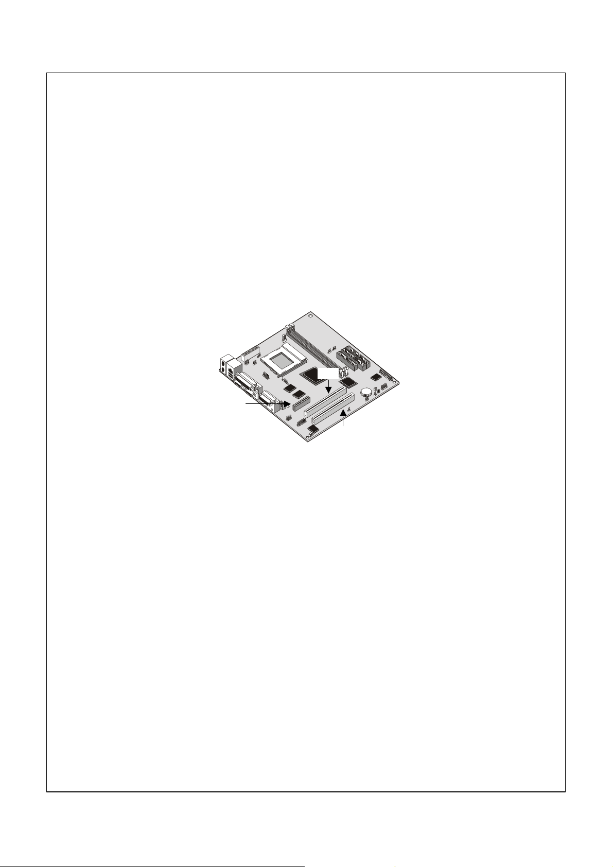
Working With Adaptors
This System Board has two 32-bit PCI expansion slots and one TV-Out/LCD
Panel Riser slot.
PCI Slots: The PCI slots can be used to install add-in cards that have the 32-bit
PCI (Peripheral Components Interconnect) interface.
TV-Out/LCD Panel Riser: The TV-Out/LCD Panel Riser slot allows for the
installation of a riser card for exporting the system’s video output to an TV
receiver or an external LCD panel.
PCI1
TV-Out/
LCD
Panel
Riser
1. Before installing an expansion card, check the documentation for the card
carefully. If the card is not Plug and Play, you may have to manually
configure the card before installation.
2. Select which expansion slot you are going to use for your add-in card.
3. In the system case, remove the blanking plate from the slot in the system
case that corresponds to the expansion slot that you are going to use.
4. Position the edge connector of the add-in card over the expansion slot.
Position the metal bracket of the card in the empty slot in the system case.
5. Install the edge connector of the add-in card into the expansion slot. Press
down quite firmly so that you are sure that the edge connector is correctly
seated in the slot.
6. Secure the metal bracket of the card in the empty slot in the system case
with a screw.
7. For some add-in cards, for example graphics adapters and network
adapters, you have to install drivers and software before you can begin
using the add in card.
PCI2
49
Page 60

Add-in Card Options
The System Board has two features that can be used if you have installed either
a fax/modem card or a network adapter card.
WOL1: Wake on LAN
If you have installed a network adapter (LAN adapter), you can use the cable
provided with the card to plug into the WOL1 connector on the System Board.
This is the Wake On LAN feature. When your system is in a power–saving
mode, any traffic through the network automatically resume the system. You
must enable this item using the Power Management page of the setup utility.
WOM1: Wake on Modem
If you have installed a fax/modem card, you can use the cable provided with the
card to plug into the WOM1 connector on the System Board. This is the Wake
On Modem feature. When your system is in a power–saving mode, any
incoming calls to the modem automatically resume the system. You must
enable this item using the Power Management page of the setup utility.
Replacing the system battery
Follow these steps to replace the battery:
1. Place the blade of a small, flat-blade screwdriver under the edge of the
retaining clip.
2. Turn the screwdriver one quarter turn, raising the clip while pressing down on
the old battery to remove it.
3. Carefully raise the retaining clip, and insert the new battery with the + symbol
facing out.
4. Insert a new 3V lithium battery IBM part number
33F8354 (battery type CR2032) into the socket and press it
down until the securing clip clicks and locks the battery in if
you replace the system battery, you need to reset the
system date and time.
Note: Before replacing the lithium battery review the lithium battery notice on
page ix.
Important: Make sure you insert the battery with the positive side on top. A
plus (+) sign indicates the positive side.
50
Page 61

CChhaapptteerr 66.. TTrroouubblleesshhoooottiinngg aannd
d
rreeccoovveerry
This chapter describes troubleshooting and recovery tools for computers that
have IBM preinstalled software. These tools are:
• ConfigSafe program
• Emergency Recovery diskette
• IBM Device Drivers and Diagnostics CD
• Product Recovery CDs
• Product Recovery program on the hard disk (2169, A20, A40, and A40p
models)
Note: Not all computers have all of these tools. Note the tools that come with
your computer.
Attention:
IBM personal computer models 2169, A20, A40, and A40p have a Product
Recovery program on a separate, hidden, hard disk drive partition. Do
not delete or alter this partition. If this partition becomes damaged or
altered, see “Ordering CDs” on page 69.
See the online About Your Software publication for information on creating an
Emergency Recovery diskette. The Emergency Recovery diskette will give you
access to the Product Recovery program through the command prompt on the
hidden hard disk drive partition.
y
If you are using any of the CDs described in this chapter, verify that your
computer primary startup sequence begins with the CD-ROM drive. See
“Changing the primary startup sequence” on page 54, if necessary.
Troubleshooting the Windows desktop with ConfigSafe
You can troubleshoot some desktop configuration errors without recovering
your entire preinstalled operating system, software, or device drivers. If your
desktop becomes damaged, unusable, or unstartable, use the ConfigSafe
program to recover your desktop to its last saved state. Use the ConfigSafe
program to correct configuration errors before using other recovery tools.
All computers with IBM-preinstalled software have the ConfigSafe program.
51
Page 62

The snapshot feature can automatically save your system configuration
information on a regular schedule, the timing of which you can select. The first
snapshot is taken the first time you start the computer.
To open the ConfigSafe program, follow these steps:
1. Shut down your operating system.
2. Turn off your computer. If the computer will not turn off after you hold
down the power button for at least four seconds, unplug the power cord
and wait a few seconds before reconnecting it.
3. For Windows 98, restart your computer in Safe Mode:
4. Turn on your computer.
5. When prompted, press and hold down the F8 key.
6. Continue to hold down F8 until the prompt menu appears. Select Safe
Mode from the menu.
7. Click the Windows Start button.
8. Select Programs CONFIGSAFE. (If this does not appear on
the menu, select FIND and search for it by typing in configsafe and
clicking OK. Double-click the file ConfigSafe to start the program.)
9. If the ConfigSafe menu shows any saved configurations, select the most
recent configuration dated before the start of the problem.
10. Click OK.
Shut down the operating system and turn off your computer.
Using ConfigSafe SOS
In the event the Windows desktop becomes unusable, ConfigSafe has a Save
Our System (SOS) feature that can be used in DOS. To access the SOS
feature of ConfigSafe, do the following.
1. Shut down your operating system.
2. Access your Command prompt:
3. For Windows 98 start the computer. Quickly press F8 when prompted
during the startup. Select the option for command prompt only.
4. At the command prompt, type cd\cfgsafe. Press Enter.
5. Type sos and press Enter.
6. Select the most recent configuration dated before the start of the problem.
7. Press Enter.
8. Restart the computer.
9. If the problem recurs, you can repeat these steps selecting a saved
configuration from an earlier date. If the problem cannot be solved by
restoring a saved configuration, see the following sections.
52
Page 63

Reinstalling the operating system
IBM Personal Computer models 2169, A20, A40, and A40p have the Product
Recovery program on a hidden partition of the hard disk. All other computer
models will use either the Product Recovery CDs, the Device Drivers and
Diagnostics CD, or the CDs or diskettes that came with your own operating
system.
Note: If you have more than one Product Recovery CD, begin with Product
Recovery CD 1.
Performing a partial or full recovery
Attention:
The Product Recovery program on the hidden hard disk drive partition
will overwrite all files on the C:\ drive only. A full recovery will restore
the operating system, device drivers, and applications. A partial recovery
will restore your operating system and device drivers without restoring
applications.
To perform a recovery of the operating system, do the following:
1. If you do not have a CD, go to step 2. If you have a CD, open the
CD-ROM drive. Insert Product Recovery CD 1. Close the drive.
2. If you can shut down your desktop normally, do so. If you cannot shut
down, proceed with the following steps anyway.
3. Turn off your computer. If the computer will not turn off after you hold
down the power button for at least four seconds, unplug the power cord
and wait a few seconds before reconnecting it.
4. Turn on your computer.
5. Wait for the prompt, To start the Product Recovery program,
press F11
6. Quickly press F11. The prompt displays for only a few seconds. If you are
using a CD, wait for the Product Recovery program menu to appear on the
screen.
7. You may have a choice of operating systems to recover. Select the
operating system you want. Otherwise, select the option given.
8. Select the recovery options you want and follow the instructions on the
screen.
9. When recovery is complete, exit the program. If necessary, remove the CD
from your CD-ROM drive.
.
Turn off, then restart the computer.
53
Page 64

Diagnosing hardware
If restoring the settings from the ConfigSafe program or reinstalling the
operating system and device drivers does not solve the problem, try using the
IBM Enhanced Diagnostics program. The IBM Enhanced Diagnostics program
helps isolate hardware problems and runs independently of the operating
system.
The IBM Enhanced Diagnostics program is an option on the menu for the
Product Recovery program on the hidden partition. If you are running the
Enhanced Diagnostics program from a Product Recovery CD or the Device
Drivers and Diagnostics CD, verify that the primary startup sequence begins
with the CD-ROM drive.
To start the IBM Enhanced Diagnostics program, do the following:
1. If you have a CD, place it in the CD-ROM drive. Shut down
the operating system and turn off the computer. If you do not have a CD,
go to step 2.
2. Turn on the computer. When prompted To start the Product
Recovery program,
only seconds.
3. From the Product Recovery program menu, select System Utilities.
4. From the System Utilities menu, select Run Diagnostics. The IBM
Enhanced Diagnostics program starts.
5. When the program finishes, if necessary, remove the CD from the
CD-ROM drive.
6. Turn off the computer.
7. If you changed the primary startup sequence, restore it to the original
settings. Use the instructions in the next section.
You can create an IBM Enhanced Diagnostics diskette for further security.
quickly press F11. The prompt displays for
Changing the primary startup sequence
If you inserted a CD in the CD-ROM drive and your computer does not read the
CD immediately on startup, change the primary startup device using the
Configuration/Setup Utility program. To change the startup sequence, do the
following:
1. Turn off your computer.
2. Turn on your computer.
3. When the Configuration/Setup Utility program prompt appears, quickly
press DEL. The prompt appears for only seconds.
4. From the Configuration/Setup Utility menu, select Advanced BIOS features.
5. From the Advanced BIOS Features, select First Boot Device.
6. Note the device currently selected as the first startup device and write it
down for future reference. You must restore this setting when you finish.
7. Change the first startup device to your CD-ROM drive.
8. Press Esc until you return to the Configuration/Setup Utility program menu.
54
Page 65

9. Select Save Settings and press Enter before you exit from the program.
Turn off your computer.
Recovering or installing device drivers
Read the following information before installing or reinstalling individual
device drivers.
Restoring the factory-preinstalled device drivers is part of the Product
Recovery program, Product Recovery CDs, and the Device Drivers and
Diagnostics CD.
If you have an IBM Model 2169, A20, A40, or A40p computer, device drivers
are located on the C:\ drive. Other device drivers are on the software media that
come with individual devices.
Notes:
1. Before you can recover or install device drivers, your operating system
must be installed on your computer.
2. Before you start recovering or installing device drivers, make sure you have
the documentation and software media for the device. Device drivers for
IBM devices and the instructions to install them (README.TXT) are
located on the Product Recovery CDs, the Device Drivers and Diagnostics
CD or, for IBM Personal Computer models 2169,A20, A40, and A40p, in
the C:\IBMTOOLS\DRIVERS directory.
3. The latest device drivers are also available on the World Wide Web at
http://www.ibm.com/pc/support.
55
Page 66

Troubleshooting
Note
If your computer does not start when you press the power switch, do
the following:
– Make sure your computer and monitor are connected to working
electrical outlets.
– Make sure all cables are securely connected to the correct locations.
If this does not correct the problem, have the computer serviced.
Computer problems can be caused by hardware, software, or user error (for
example, pressing the wrong key). You can use the diagnostic aids discussed in
this chapter to help you solve such problems yourself or gather helpful
information you can pass on to a service technician.
You can check the hardware by following the procedures in this chapter.
You can also use the diagnostic programs provided with your computer (see
“IBM Enhanced Diagnostics program” on page 65 for a description of these
programs).
If the hardware checks out, and you have not made a user error, you might
have a software problem. If you suspect that you have a software problem and
your computer comes with IBM-preinstalled software, see “IBM Enhanced
Diagnostics program” on page 65 for information about how to run the IBM
Enhanced diagnostics program provided by IBM. Also see the operating
system documentation supplied with your computer. If you have installed
software applications yourself, see the documentation supplied with the
software.
The following tools are available to diagnose hardware-related problems:
– Power-on self-test (POST)
– Error codes and messages
– IBM Enhanced Diagnostics program
56
Page 67

Power-on self-test (POST) Each time you turn on your computer, it performs a series of tests that
check the basic operation of the base computer. This series of tests is called
the power-on self-test (POST). POST does the following:
– Checks basic system board operations
– Checks the memory operation
– Compares the current system configuration with that established by the
Configuration/Setup Utility program
– Starts the video operation
– Verifies that the diskette drives are working
– Verifies that the hard disk drive and the CD-ROM drive are working
If Quick Power-On Self-Test is set to Disabled, numbers showing the amount of
memory being tested appear in the top-left corner of the screen until the total
amount of memory in the system is reached. Options for viewing the POST
screen and memory count or accessing the Configuration/Setup Utility program
appear in the lower-left corner of the screen at power on. Quick mode is the
default mode of operation.
Note: The amount of available memory shown might be somewhat less than
expected because of basic input/output system (BIOS) shadowing in random
access memory (RAM). If POST finishes without detecting any problems, the
first screen of your operating system or application program appears if you
have not set a power-on password.
If you have set a power-on password, a password prompt appears. You must
enter your password before the first screen of your operating system or
application program will appear.
If POST detects no problems, you will hear a single beep. If POST detects a
problem, you may hear multiple beeps or no beep. In most cases, an error code
appears on the screen, and in some cases a description of the error is
displayed beside the code. (Note that the screen will sometimes display multiple
error codes and descriptions.)
Diagnostic error codes and messages
Diagnostic codes and messages appear if a hardware problem is detected by
one of the IBM Enhanced Diagnostics test programs or if POST detects a
problem. Along with error codes, the messages present text information
that can be used to identify a failing part.
57
Page 68

POST error
The computer might display more than one error message. Often, the first error
to occur causes subsequent errors. When using the POST message
information in this section, always begin by following the suggested action for
the first error message that appears on your computer screen.
Code description and action:
Floppy disk(s) fail (40)
Hard disk(s) Diagnosis fail
Primary master hard disk fail
Primary slave hard disk fail
Secondary master hard disk fail
Secondary slave hard disk fail
Keyboard is locked out - Unlock the key
Keyboard error or no keyboard present
Memory test fail
CMOS checksum error - Defaults loaded
CMOS battery failed
Diskette drive problems
Diskette drive in-use, light stays on, or the system
bypasses the diskette drive.
If there is a diskette in the drive, verify that:
1. The diskette drive is enabled. Use the Configuration/Setup Utility program
to check this. For more information, see Chapter 4, “Using the
Configuration/Setup Utility program” on page 18.
2. The computer is checking for the diskette drive in the startup sequence.
Use Setup Utility program to verify this.
3. The diskette you are using is good and not damaged. Try inserting another
diskette if you have one.
4. The diskette is inserted correctly, with its label up and its metal shutter end
first in the drive.
5. The diskette contains the necessary files to start the computer (the diskette
must be startable).
6. The diskette drive cable is properly installed and securely connected.
7. There is no problem with your software program (see “Software problems”
on page 64).
If you cannot correct the problem, have the computer serviced.
58
Page 69

Monitor Problems
General monitor problems.
Some IBM monitors have their own self-tests. If you suspect a problem with
our monitor, see the information supplied with the monitor for adjustment and
testing instructions.
If you cannot find the problem, check the other listings on monitor problems in
this section.
If you cannot correct the problem, have the computer serviced.
Wavy, unreadable, rolling, distorted, or jittery screen
images.
If the monitor self-tests show that the monitor is working properly, verify that:
1.The location of the monitor is appropriate. Magnetic fields around other
devices, such as transformers, appliances, fluorescent lights, and other
monitors might be causing the problem. To determine if the location is causing
the problem:
• Turn off the monitor. (Moving a color monitor while it is turned on might
cause screen discoloration.)
• Adjust the placement of the monitor and other devices so that they are at
least 305 mm (12 in.) apart. Also, when relocating the monitor, be sure it is
at least 75 mm (3 in.) from the diskette drives to prevent diskette
driveread/write errors.
• Turn on the monitor.
2. An IBM monitor signal cable is properly connected to the monitor and
computer, and that the cable is installed securely. Non-IBM monitor signal
cables might cause unpredictable problems.
3. You are not trying to run your monitor at a higher refresh rate than the
monitor supports. See the documentation supplied with your monitor for
supported refresh rates. Note: An enhanced monitor signal cable with
additional shielding might be available for your monitor. See your IBM reseller
or marketing representative for information.If you cannot correct the problem,
have the computer serviced.
59
Page 70

Screen flickers.
Set the monitor for the highest, noninterlaced refresh rate supported by your
monitor and the video controller in your computer. Attention: Using a
resolution or refresh rate that is not supported by your monitor might damage it.
You can reset the refresh rate through your operating system, following the
instructions provided in the README files. See your operating system
documentation for further information on monitor settings.
If this does not correct the problem, have the monitor and computer serviced.
The monitor works when you turn on the system, but goes blank when you start
some application programs. Verify that:
1. The monitor signal cable is securely connected to the monitor and to the
monitor connector on the graphics adapter. For the location of the monitor
connector on the graphics adapter installed in your computer, see “external
color coding” connections on page 9.
2. The necessary device drivers for the application programs are installed. If
you cannot correct the problem, have the computer serviced.
The monitor works when you turn on the system, but
goes blank after some period of computer inactivity.
The computer is probably set for energy savings using one of the power
management settings. If the power management features are enabled, disabling
or changing the settings might solve the problem (see “Power management
features” on page 30).
If you cannot correct the problem, have the computer serviced.
Blank screen.
Verify that
1. The monitor power cord is plugged into a working electrical outlet.
2. The monitor is turned on and the Brightness and Contrast controls are
adjusted correctly.
3. The monitor signal cable is securely connected to the monitor and the
monitor connector on the system board. To find the monitor connector on
the system board, see “external color coding connections on page 9
If you cannot correct the problem, have the computer serviced.
60
Page 71

Only the cursor appears.
Have the computer serviced.
Wrong characters appear on the screen.
Have the computer serviced.
General problems
The computer does not start when you press the power switch. Verify that:
1. All cables are securely connected to the proper connectors on the
computer. For the location of the connectors, see “external color coding”
connections on page 9
2. The computer cover is properly installed.
3. If you cannot correct the problem, have the computer serviced.
Problems such as a broken cover lock or indicator lights not working.
Have the computer serviced.
Intermittent problems
A problem occurs only occasionally and is difficult to detect.
Verify that:
1. All cables and cords are securely connected to the rear of the computer
and to attached devices.
2. When the computer is turned on, the fan grill is not blocked (there is air
flow around the grill), and the fans are working. If airflow is blocked or the
fans are not working, the computer might overheat.
3. If SCSI devices are installed, the last external device in each SCSI chain is
terminated correctly. (See your SCSI documentation.)
If you cannot correct the problem, have the computer serviced.
Keyboard, mouse, or pointing device problems
All or some keys on the keyboard do not work.
Verify that: The computer and the monitor are turned on. The keyboard cable is
securely connected to the keyboard connector on the computer. For the location
of the keyboard connector, see page 9 “external color connections”.
61
Page 72

If you cannot correct the problem, have the computer serviced.
The mouse or pointing device does not work.
Verify that:
1. The mouse or pointing-device cable is securely attached to the proper
connector on the computer. Depending on the type of mouse you have, the
mouse cable will connect to either the mouse or serial connector. To find
the mouse and serial connectors, see “external color coding” connections
on page 9
2. The mouse is clean. See “Cleaning your mouse” on page 16.
3. The device drivers for the mouse are installed correctly.
If you cannot correct the problem, have the computer and the device serviced.
Memory Problems.
The amount of memory displayed is less than the
amount of memory installed.
The amount of available memory shown might be somewhat less than expected
because basic input/output system (BIOS) shadowing takes some random
access memory (RAM), video takes 1 MB, and ACP and USB also can take up
to 1 MB.
Verify that:
1. You have installed the correct type of DIMMs for your computer. See
“Working with memory” on page 45 for instructions on adding DIMMs.
2. The DIMMs are properly installed and securely connected.
3. If you added or removed memory, you saved the new configuration before
exiting the Configuration/Setup Utility program. If the problem persists, run
the memory test from the diagnostic program supplied with your computer.
(See “IBM Enhanced Diagnostics program” on page 65 for further
information.) The system might have detected a bad DIMM and
automatically reallocated memory to enable your computer to continue to
operate.
If you cannot correct the problem, have the computer serviced.
Option problems
An IBM option that was just installed does not work.
Verify that:
62
Page 73

1. The option is designed for your computer.
2. You followed the installation instructions supplied with the option and in
Chapter 5, “Installing options” on page 39.
3. All option files (if required) are installed correctly. See “Installing files from
Option Diskettes” on page 66 for information about installing option files.
4. You have not loosened any other installed options or cables.
5. If the option is an adapter, you have provided enough hardware resources
for the adapter to function correctly. See the documentation supplied with
the adapter (as well as the documentation for any other installed adapters)
to determine the resources required for each adapter.
6. You updated the configuration information in the Configuration/Setup Utility
program, if necessary, and have no conflicts. For more information, see
Chapter 4, “Using the Configuration/Setup Utility program” on page 18. If
the problem persists, run the diagnostic programs. (See “IBM Enhanced
Diagnostics program” on page 65 for information about diagnostic
programs provided with your computer.)
If you cannot correct the problem, have the computer serviced.
An IBM option that previously worked does not work
now.
Verify that all option hardware and cable connections are secure. If the option
comes with its own test instructions, use those instructions to test the option. If
the failing option is a SCSI option, verify that:
1. The cables for all external SCSI options are connected correctly.
2. The last option in each SCSI chain, or the end of the SCSI cable, is
terminated correctly.
3. All external SCSI options are turned on. External SCSI options must be
turned on before the system is turned on. For more information, see the
SCSI documentation that came with your SCSI device or devices.
If you cannot correct the problem, have the computer serviced.
Parallel-port problems
The parallel port cannot be accessed.
1. Each port is assigned a unique address. For information on how to set a
new port address, see Chapter 4, “Using the Configuration/Setup Utility
program” on page 18
2. The parallel-port adapter, if you added one, is properly installed and firmly
seated. See Chapter 5, “Installing options” on page 39 for instructions on
adding adapters.
63
Page 74

If you cannot correct the problem, have the computer serviced.
Serial-port problems
The serial port cannot be accessed.
1. Each port is assigned a unique address. For information on how to set a
new port address, see Chapter 4, “Using the Configuration/Setup Utility
program” on page 18
2. The serial-port adapter, if you added one, is properly installed and firmly
seated. See Chapter 5, “Installing options” on page 39 for instructions on
adding adapters.
If you cannot correct the problem, have the computer serviced.
Printer problems
The printer does not work.
Check:
1. The printer is turned on and is online.
2. The printer signal cable is securely connected to the correct parallel, serial,
or USB port on the computer. (See external color coding connections” on
page 9 for the location of the parallel, serial, and USB ports.)
Note: Non-IBM printer signal cables might cause unpredictable problems.
3. You have assigned the printer port correctly in your operating system or
application program.
4. You have assigned the printer port correctly in the Configuration/Setup
Utility program. For more information, see Chapter 4, “Using the
Configuration/Setup Utility program” on page 18.
5. If the problem persists, run the tests described in the documentation that
comes with your printer.
If you cannot correct the problem, have the computer serviced.
Software problems
Is your software program OK?
To determine if problems are caused by installed software, verify that:
1. Your computer has the minimum memory requirements needed to use the
software. See the information supplied with the software to verify memory
requirements.
2. If you have just installed an adapter or memory, you might have a memory
address conflict.
64
Page 75

3. The software is designed to operate on your computer.
4. Other software works on your computer.
5. The software you are using works on another computer. If you received any
error messages while using the software program, see the information
supplied with the software for a description of the messages and solutions
to the problem.
If you cannot correct the problem, have the computer serviced.
Universal Serial Bus port problems
The Universal Serial Bus ports cannot be accessed. Verify that the USB device
is properly installed and firmly seated.
If you cannot correct the problem, have the computer serviced.
IBM Enhanced Diagnostics program
You can run the IBM Enhanced Diagnostics program from a hidden
partition of your hard disk where a copy of your preinstalled programs and
diagnostics programs is kept. You can also create an IBM Enhanced
Diagnostics diskette image from the service partition if your computer comes
with a preinstalled operating system. The user interface for running the
diagnostics utility programs is provided by WaterGate Software PC-Doctor.
The IBM Enhanced Diagnostics program will isolate your computer hardware
from software that was preinstalled (or that you have installed) on your hard
disk. The programs run independently of the operating system, and must be
run either from CD or diskette.
You can use this program to test the hardware components of your computer.
This method of testing is generally used when other methods are not accessible
or have not been successful in isolating a problem suspected to be hardware
related.
To start the IBM Enhanced Diagnostics program from the hidden partition, do
the following:
1. Turn off your computer and any attached devices.
2. Turn on all attached devices; then turn on your computer.
3. When you see To start the IBM Product Recovery Program,
press F11
4. Select System Utilities and press Enter
5. A new menu opens with the options for viewing system utilities:
• Run Diagnostics
• Create a diagnostic diskette
• System Information
• Create a Recovery Repair diskette
6. Select Run Diagnostics to open the IBM Enhanced Diagnostics program to
try to track down a problem. Select System Information to display the
current computer configuration.
, press the F11 key. The Product Recovery Program will load.
65
Page 76

7. When you finish running the diagnostic program, press Esc and turn off
the computer.
To create an IBM Enhanced Diagnostics diskette from the image on the hidden
partition:
1. Turn off your computer and any attached devices.
2. Turn on all attached devices; then turn on your computer.
3. When you see To start the IBM Product Recovery Program,
press F11
, press the F11 key. The Product Recovery Program will load.
4. Select System Utilities and press Enter.
5. A new menu opens with the options for viewing system utilities:
• Run Diagnostics
• Create a diagnostic diskette
• System information
• Create a Recovery Repair diskette
6. Select Create a diagnostic diskette and press Enter. Then follow the
instructions on the screen. Other diagnostic programs on the Software Selections CD
The Software Selections CD that comes with your computer also contains
diagnostic programs designed specifically for certain operating
environments (Windows 98). Because these versions work with the operating
system, they not only test the hardware, but also analyze certain software
components of your computer. They are especially useful in isolating problems
related to the operating system and device drivers.
Recovering from a POST/BIOS update failure If power to your computer is interrupted while POST/BIOS is being
updated (flash update), your computer might not restart correctly. If this
happens, use the same procedure that is used to erase a lost or forgotten
password to recover from the failure. See “Erasing a lost or forgotten
password” on page 38.
Installing files from Option Diskettes An optional device or adapter might come with a diskette. Diskettes that
are included in option packages usually contain files that the system needs
for recognizing and activating the options. Until you install the necessary
files, the new device or adapter might cause error messages.
If your optional device or adapter comes with a diskette, you might need to
install some configuration (.CFG) files or diagnostic (.EXE or .COM) files
from the diskette to your hard disk. See the documentation that comes
with the option to determine if you need to install files.
66
Page 77

CChhaapptteerr 77.. GGeettttiinngg hheellpp,, sseerrvviiccee,, aannd
d
aaddddiittiioonnaall IInnffoorrmmaattiioon
If you need help, service, technical assistance, or just want more information
about IBM products, you will find a wide variety of sources available from IBM
to assist you.
IBM Technical Support Home Page The IBM Personal Systems Group support site provides a wide range of
technical support information and solutions. This support site is superior in its
ability to deliver comprehensive, up-to-date technical information for your
specific support needs. The categorization of technical information on the site
enables you to easily navigate directly to the support needed for your systems
and options. By profiling on the site, you are presented only the information
specific to your environment every time you visit the site. Profiling also gives
you access to Online Assistant, Discussion Forums, and Proactive e-mail.
Proactive e-mail allows you to receive the latest technical tips for your machine
through e-mail.
The IBM Personal Systems Group support site can be accessed at:
http://www.ibm.com/pc/support
Warranty Service To obtain warranty service for the Machine, contact your reseller or IBM. You
may be required to present proof of purchase.
n
Warranty Upgrades You may be able to upgrade your standard hardware warranty service or extend
the service beyond the warranty period.
To purchase warranty upgrades please contact your IBM reseller or marketing
representative.
Enhanced PC Support Enhanced PC support may be purchased from the IBM EMEA PC Helpcentre.
This will entitle you to the following assistance:
67
Page 78

• Assistance with the setup of the system unit
• Up and running support for preloaded or bundled operating system and
applications
Note:
Up and running support is defined as installing the application, clicking on
its program icon and verifying start up of the application.
• Assistance with the installation of supported Options By IBM
• Assistance with the installation of supported non-IBM options when
purchased through IBM Direct/Shop IBM and bundled with an IBM system
• Information about the customer's system and supplied software
• Fault analysis support to ensure that the hardware is working fault-free, or
returning the machine to factory-installed defaults
• Advice on where to obtain hardware and/or software updates from the
Internet.
• Assistance with the installation of Supported OEM Options.
• Assistance with basic usage queries on preloaded/bundled software.
• Assistance with the installation/setup and configuration of device drivers.
• Assistance with the setup and installation of printers and printer software.
• Assistance with the installation of supported, non preloaded operating
systems.
To purchase Enhanced PC Support please call your Country number below,
Country Phone:
Austria Österreich 01-54658 5060
Belgium - Dutch Belgie 02-714 35 70
Belgium - French Belgique 02-714 35 15
Denmark Danmark 35 25 02 91
Finland Suomi 09-22 931 840
France France 01 69 32 40 40
Germany Deutschland 069-6654 9040
Ireland Ireland 01-815 9202
Italy Italia 02 4827 5040
Luxembourg Luxembourg 298-977 5063
Netherlands Nederland 020-504 0501
Norway Norge 23 05 32 40
Portugal Portugal 21-791 51 47
Spain España 91-662 49 16
Sweden Sverige 08-751 52 27
Switzerland Schweiz/Suisse/Svizzera 0848-80-52-52
United Kingdom United Kingdom 01475-555 055
In all other countries, contact your IBM reseller or IBM marketing
representative.
68
Page 79

Response time will vary depending on the number and complexity of incoming
calls.
An updated list of telephone numbers is maintained on the IBM PC Support
website.
Other IBM Websites
For further information on IBM, visit the following pages:
IBM Corporate Homepage
http://www.ibm.com
IBM Personal Systems Group
http://www.ibm.com/pc
You can select a country-specific Web site from these pages.
Ordering CDs
For more information on obtaining a replacement Product Recovery CD for IBM
personal computer models 2169, A20, A40, and A40p, see the IBM personal
computing support page at http://www.ibm.com/pc/support on the World
Wide Web, Or contact your Enhanced PC support helpline.
69
Page 80

AAppppeennddiixx 11.. PPrroodduucctt wwaarrrraannttyy aannd
d
nnoottiiccees
This appendix includes product warranty and other notices.
s
Warranty Statements
The warranty statements consist of two parts: Part 1 and Part 2. Part 1 varies
by country. Part 2 is the same for both statements. Be sure to read both Part 1
and Part 2.
Worldwide except Canada, Puerto Rico, Turkey, and United States
(Z125-5697-01 11/97) (“IBM Statement of Warranty Worldwide except
Canada, Puerto Rico, Turkey, United States (Part 1 - General Terms)”)
Worldwide Country-Unique Terms (“Part 2 -Worldwide Country-Unique
Terms” on page)
IBM Statement of Warranty Worldwide except Canada, Puerto Rico, Turkey, United States (Part 1 - General Terms)
This Statement of Warranty includes Part 1 - General Terms and Part 2 Country-unique Terms.The terms of Part 2 may replace or modify those of Part
1. The warranties provided by IBM in this Statement of Warranty apply only to
Machines you purchase for your use, and not for resale, from IBM or your
reseller.
The term “Machine” means an IBM machine, its features, conversions,
upgrades, elements, or accessories, or any combination of them. The term
”Machine” does not include any software programs, whether pre-loaded with the
Machine, installed subsequently or otherwise. Unless IBM specifies otherwise,
the following warranties apply only in the country where you acquire the
Machine. Nothing in this Statement of Warranty affects any statutory rights of
consumers that cannot be waived or limited by contract. If you have any
questions, contact IBM or your reseller.
70
Page 81

Machine - NetVista A40p Types 6569, 6649, 6579, PC 300PL Types 6565, 6584, and
6594
Warranty period*
• Bangladesh, China, Hong Kong, India, Indonesia, Malaysia, Philippines, Singapore,
Sri Lanka, Taiwan, Thailand, and Vietnam - Parts: Three (3) years Labor: One (1)
year**
• Japan - Parts: One (1) year Labor: One (1) year
• All other countries not listed - Parts: Three (3) years Labor: Three (3) years
Machine - NetVista A20 Type 6269, PC 300GL Types 6268, 6288, 6563, 6564 and 6574
Warranty period*
• EMEA and Argentina - Parts: Three (3) years Labor: Three (3) years
• Japan - Parts: One (1) year Labor: One (1) year
• All other countries not listed - Parts: Three (3) years Labor: One (1) year **
•
Machine - NetVista A40 Types 6568, 6648 and 6578
Warranty period*
• United States, Canada, EMEA, and Latin America - Parts: Three (3) years Labor:
Three (3) years
• Japan - Parts: One (1) year Labor: One (1) year
• All other countries not listed - Parts: Three (3) years Labor: One (1) year **
Machine - PC 300 Type 2169, Europe, Middle East and Africa only
Warranty period*
Parts: One (1) Year Labor: One (1) Year, Customer Carry in Repair.
* Contact your place of purchase for warranty service information. Some IBM Machines
are eligible for on-site warranty service depending on the country where service is
performed.
** IBM will provide warranty service without charge for:
1. parts and labor during the first year of the warranty period
2. parts only, on an exchange basis, in the second and third years of the warranty period.
IBM will charge you for any labor it provides in performance of the repair or
replacement.
The IBM Warranty for Machines
IBM warrants that each Machine 1) is free from defects in materials and
workmanship and 2) conforms to IBM’s Official Published Specifications. The
warranty period for a Machine is a specified, fixed period commencing on its
Date of Installation. The date on your sales receipt is the Date of Installation,
unless IBM or your reseller informs you otherwise.
During the warranty period IBM or your reseller, if approved by IBM to
provide warranty service, will provide repair and exchange service for the
71
Page 82

Machine, without charge, under the type of service designated for the Machine
and will manage and install engineering changes that apply to the Machine.
If a Machine does not function as warranted during the warranty period, and
IBM or your reseller are unable to either 1) make it do so or 2) replace it with
one that is at least functionally equivalent, you may return it to your place of
purchase and your money will be refunded. The replacement may not be new,
but will be in good working order.
Extent of Warranty
The warranty does not cover the repair or exchange of a Machine resulting
from misuse, accident, modification, unsuitable physical or operating
environment, improper maintenance by you, or failure caused by a product for
which IBM is not responsible. The warranty is voided by removal or alteration
of Machine or parts identification labels.
THESE WARRANTIES ARE YOUR EXCLUSIVE WARRANTIES AND
REPLACE ALL OTHER WARRANTIES OR CONDITIONS, EXPRESS OR
IMPLIED, INCLUDING, BUT NOT LIMITED TO, THE IMPLIED
WARRANTIES OR CONDITIONS OF MERCHANTABILITY AND FITNESS
FOR A PARTICULAR PURPOSE. THESE WARRANTIES GIVE YOU
SPECIFIC LEGAL RIGHTS AND YOU MAY ALSO HAVE OTHER RIGHTS
WHICH VARY FROM JURISDICTION TO JURISDICTION. SOME
JURISDICTIONS DO NOT ALLOW THE EXCLUSION OR LIMITATION
OF EXPRESS OR IMPLIED WARRANTIES, SO THE ABOVE EXCLUSION
OR LIMITATION MAY NOT APPLY TO YOU. IN THAT EVENT, SUCH
WARRANTIES ARE LIMITED IN DURATION TO THE WARRANTY
PERIOD. NO WARRANTIES APPLY AFTER THAT PERIOD.
Items Not Covered by Warranty
IBM does not warrant uninterrupted or error-free operation of a Machine.
Unless specified otherwise, IBM provides non-IBM machines WITHOUT
WARRANTIES OF ANY KIND.
Any technical or other support provided for a Machine under warranty, such
as assistance via telephone with “how-to” questions and those regarding
Machine set-up and installation, will be provided WITHOUT WARRANTIES
OF ANY KIND.
Warranty Service
To obtain warranty service for the Machine, contact your reseller or IBM. You
may be required to present proof of purchase.
72
Page 83

IBM or your reseller provides certain types of repair and exchange service,
either at your location or at a service center, to keep Machines in, or restore
them to, conformance with their Specifications. IBM or your reseller will
inform you of the available types of service for a Machine based on its country
of installation. IBM may repair the failing Machine or exchange it at its
discretion.
When warranty service involves the exchange of a Machine or part, the item
IBM or your reseller replaces becomes its property and the replacement
becomes yours. You represent that all removed items are genuine and
unaltered. The replacement may not be new, but will be in good working order
and at least functionally equivalent to the item replaced. The replacement
assumes the warranty service status of the replaced item.
Any feature, conversion, or upgrade IBM or your reseller services must be
installed on a Machine which is 1) for certain Machines, the designated,
serial-numbered Machine and 2) at an engineering-change level compatible
with the feature, conversion, or upgrade. Many features, conversions, or
upgrades involve the removal of parts and their return to IBM. A part that
replaces a removed part will assume the warranty service status of the
removed part.
Before IBM or your reseller exchanges a Machine or part, you agree to remove
all features, parts, options, alterations, and attachments not under warranty
service.
You also agree to
1. ensure that the Machine is free of any legal obligations or restrictions that
prevent its exchange;
2. obtain authorization from the owner to have IBM or your reseller service a
Machine that you do not own; and
3. where applicable, before service is provided
a. follow the problem determination, problem analysis, and service request
procedures that IBM or your reseller provides,
b. secure all programs, data, and funds contained in a Machine,
c. provide IBM or your reseller with sufficient, free, and safe access to
your facilities to permit them to fulfill their obligations, and
d. inform IBM or your reseller of changes in a Machine’s location.
IBM is responsible for loss of, or damage to, your Machine while it is 1) in
IBM’s possession or 2) in transit in those cases where IBM is responsible for
the transportation charges.
73
Page 84

Neither IBM nor your reseller is responsible for any of your confidential,
proprietary or personal information contained in a Machine which you return
to IBM or your reseller for any reason. You should remove all such information
from the Machine prior to its return.
Production Status
Each IBM Machine is manufactured from new parts, or new and used parts. In
some cases, the Machine may not be new and may have been previously
installed. Regardless of the Machine’s production status, IBM’s appropriate
warranty terms apply.
Limitation of Liability
Circumstances may arise where, because of a default on IBM’s part or other
liability, you are entitled to recover damages from IBM. In each such instance,
regardless of the basis on which you are entitled to claim damages from IBM
(including fundamental breach, negligence, misrepresentation, or other contract
or tort claim), IBM is liable for no more than
1. damages for bodily injury (including death) and damage to real property
and tangible personal property; and
2. the amount of any other actual direct damages, up to the greater of U.S.
$100,000 (or equivalent in local currency) or the charges (if recurring, 12
months’ charges apply) for the Machine that is the subject of the claim.
This limit also applies to IBM’s suppliers and your reseller. It is the
maximum for which IBM, its suppliers, and your reseller are collectively
responsible.
UNDER NO CIRCUMSTANCES IS IBM LIABLE FOR ANY OF THE
FOLLOWING: 1) THIRD-PARTY CLAIMS AGAINST YOU FOR DAMAGES
(OTHER THAN THOSE UNDER THE FIRST ITEM LISTED ABOVE); 2)
LOSS OF, OR DAMAGE TO, YOUR RECORDS OR DATA; OR 3) SPECIAL,
INCIDENTAL, OR INDIRECT DAMAGES OR FOR ANY ECONOMIC
CONSEQUENTIAL DAMAGES (INCLUDING LOST PROFITS OR
SAVINGS), EVEN IF IBM, ITS SUPPLIERS OR YOUR RESELLER IS
INFORMED OF THEIR POSSIBILITY. SOME JURISDICTIONS DO NOT
ALLOW THE EXCLUSION OR LIMITATION OF INCIDENTAL OR
CONSEQUENTIAL DAMAGES, SO THE ABOVE LIMITATION OR
EXCLUSION MAY NOT APPLY TO YOU.
74
Page 85

Part 2 -Worldwide Country-Unique Terms
ASIA PACIFIC
AUSTRALIA: The IBM Warranty for Machines: The following paragraph is
added to this Section: The warranties specified in this Section are in addition to
any rights you may have under the Trade Practices Act 1974 or other
legislation and are only limited to the extent permitted by the applicable
legislation.
Extent of Warranty: The following replaces the first and second sentences of
this Section: The warranty does not cover the repair or exchange of a Machine
resulting from misuse, accident, modification, unsuitable physical or operating
environment, operation in other than the Specified Operating Environment,
improper maintenance by you, or failure caused by a product for which IBM is
not responsible.
Limitation of Liability: The following is added to this Section: Where IBM is
in breach of a condition or warranty implied by the Trade Practices Act 1974,
IBM’s liability is limited to the repair or replacement of the goods or the
supply of equivalent goods. Where that condition or warranty relates to right
to sell, quiet possession or clear title, or the goods are of a kind ordinarily
acquired for personal, domestic or household use or consumption, then none
of the limitations in this paragraph apply.
PEOPLE’S REPUBLIC OF CHINA: Governing Law: The following is added to
this Statement: The laws of the State of New York govern this Statement.
INDIA: Limitation of Liability: The following replaces items 1 and 2 of this
Section:
1. liability for bodily injury (including death) or damage to real property and
tangible personal property will be limited to that caused by IBM’s
negligence;
2. as to any other actual damage arising in any situation involving
nonperformance by IBM pursuant to, or in any way related to the subject
of this Statement of Warranty, IBM’s liability will be limited to the charge
paid by you for the individual Machine that is the subject of the claim.
NEW ZEALAND: The IBM Warranty for Machines: The following paragraph
is added to this Section: The warranties specified in this Section are in addition
to any rights you may have under the Consumer Guarantees Act 1993 or other
legislation which cannot be excluded or limited. The Consumer Guarantees Act
1993 will not apply in respect of any goods which IBM provides, if you require
the goods for the purposes of a business as defined in that Act.
Limitation of Liability: The following is added to this Section: Where
Machines are not acquired for the purposes of a business as defined in the
Consumer Guarantees Act 1993, the limitations in this Section are subject to
the
limitations in that Act.
75
Page 86

EUROPE, MIDDLE EAST, AFRICA (EMEA)
The following terms apply to all EMEA countries.
The terms of this Statement of Warranty apply to Machines purchased from an
IBM reseller. If you purchased this Machine from IBM, the terms and
conditions of the applicable IBM agreement prevail over this warranty
statement.
Warranty Service
If you purchased an IBM Machine in Austria, Belgium, Denmark, Estonia,
Finland, France, Germany, Greece, Iceland, Ireland, Italy, Latvia, Lithuania,
Luxembourg, Netherlands, Norway, Portugal, Spain, Sweden, Switzerland or
United Kingdom, you may obtain warranty service for that Machine in any of
those countries from either (1) an IBM reseller approved to perform warranty
service or (2) from IBM.
If you purchased an IBM Personal Computer Machine in Albania, Armenia,
Belarus, Bosnia and Herzegovina, Bulgaria, Croatia, Czech Republic, Georgia,
Hungary, Kazakhstan, Kirghizia, Federal Republic of Yugoslavia, Former
Yugoslav Republic of Macedonia (FYROM), Moldova, Poland, Romania,
Russia,
Slovak Republic, Slovenia, or Ukraine, you may obtain warranty service for
that Machine in any of those countries from either (1) an IBM reseller
approved to perform warranty service or (2) from IBM.
The applicable laws, Country-unique terms and competent court for this
Statement are those of the country in which the warranty service is being
provided. However, the laws of Austria govern this Statement if the warranty
service is provided in Albania, Armenia, Belarus, Bosnia and Herzegovina,
Bulgaria, Croatia, Czech Republic, Federal Republic of Yugoslavia, Georgia,
Hungary, Kazakhstan, Kirghizia, Former Yugoslav Republic of Macedonia
(FYROM), Moldova, Poland, Romania, Russia, Slovak Republic, Slovenia, and
Ukraine.
The following terms apply to the country specified:
EGYPT: Limitation of Liability: The following replaces item 2 in this Section:
2. as to any other actual direct damages, IBM’s liability will be limited to the
total amount you paid for the Machine that is the subject of the claim.
Applicability of suppliers and resellers (unchanged).
FRANCE: Limitation of Liability: The following replaces the second sentence
of the first paragraph of this Section: In such instances, regardless of the basis
on which you are entitled to claim damages from IBM, IBM is liable for no
more than: (items 1 and 2 unchanged).
GERMANY: The IBM Warranty for Machines: The following replaces the first
sentence of the first paragraph of this Section: The warranty for an IBM
Machine covers the functionality of the Machine for its normal use and the
Machine’s conformity to its Specifications.
The following paragraphs are added to this Section: The minimum warranty
76
Page 87

period for Machines is six months.
In case IBM or your reseller are unable to repair an IBM Machine, you can
alternatively ask for a partial refund as far as justified by the reduced value of
the unrepaired Machine or ask for a cancellation of the respective agreement
for such Machine and get your money refunded.
Extent of Warranty: The second paragraph does not apply.
Warranty Service: The following is added to this Section: During the warranty
period, transportation for delivery of the failing Machine to IBM will be at
IBM’s expense.
Production Status: The following paragraph replaces this Section: Each
Machine is newly manufactured. It may incorporate in addition to new parts,
re-used parts as well.
Limitation of Liability: The following is added to this Section: The limitations
and exclusions specified in the Statement of Warranty will not apply to
damages caused by IBM with fraud or gross negligence and for express
warranty.
In item 2, replace ²U.S. $100,000² with ²1.000.000 DEM.²
The following sentence is added to the end of the first paragraph of item 2:
IBM’s liability under this item is limited to the violation of essential contractual
terms in cases of ordinary negligence.
IRELAND: Extent of Warranty: The following is added to this Section: Except
as expressly provided in these terms and conditions, all statutory conditions,
including all warranties implied, but without prejudice to the generality of the
foregoing all warranties implied by the Sale of Goods Act 1893 or the Sale of
Goods and Supply of Services Act 1980 are hereby excluded.
Limitation of Liability: The following replaces items one and two of the first
paragraph of this Section: 1. death or personal injury or physical damage to
your real property solely caused by IBM’s negligence; and 2. the amount of
any other actual direct damages, up to the greater of Irish Pounds 75,000 or
125 percent of the charges (if recurring, the 12 months’ charges apply) for the
Machine that is the subject of the claim or which otherwise gives rise to the
claim.
Applicability of suppliers and resellers (unchanged).
The following paragraph is added at the end of this Section: IBM’s entire
liability and your sole remedy, whether in contract or in tort, in respect of any
default shall be limited to damages.
ITALY: Limitation of Liability: The following replaces the second sentence in
the first paragraph: In each such instance unless otherwise provided by
mandatory law, IBM is liable for no more than: (item 1 unchanged) 2) as to any
other actual damage arising in all situations involving non-performance by
IBM pursuant to, or in any way related to the subject matter of this Statement
of Warranty, IBM’s liability, will be limited to the total amount you paid for the
Machine that is the subject of the claim.
Applicability of suppliers and resellers (unchanged).
77
Page 88

The following replaces the second paragraph of this Section: Unless otherwise
provided by mandatory law, IBM and your reseller are not liable for any of the
following: (items 1 and 2 unchanged) 3) indirect damages, even if IBM or your
reseller is informed of their possibility.
SOUTH AFRICA, NAMIBIA, BOTSWANA, LESOTHO AND SWAZILAND:
Limitation of Liability: The following is added to this Section: IBM’s entire
liability to you for actual damages arising in all situations involving
nonperformance by IBM in respect of the subject matter of this Statement of
Warranty will be limited to the charge paid by you for the individual Machine
that is the subject of your claim from IBM.
TURKIYE: Production Status: The following replaces this Section: IBM fulfills
customer orders for IBM Machines as newly manufactured in accordance with
IBM’s production standards.
UNITED KINGDOM: Limitation of Liability: The following replaces items 1
and 2 of the first paragraph of this Section:
1. death or personal injury or physical damage to your real property solely
caused by IBM’s negligence;
2. the amount of any other actual direct damages or loss, up to the greater of
Pounds Sterling 150,000 or 125 percent of the charges (if recurring, the 12
months’ charges apply) for the Machine that is the subject of the claim or
which otherwise gives rise to the claim.
The following item is added to this paragraph: 3. breach of IBM’s obligations
implied by Section 12 of the Sale of Goods Act 1979 or Section 2 of the Supply
of Goods and Services Act 1982.
Applicability of suppliers and resellers (unchanged).
The following is added to the end of this Section: IBM’s entire liability and
your sole remedy, whether in contract or in tort, in respect of any default will
be limited to damages.
NORTH AMERICA
CANADA: Warranty Service: The following is added to this section: To obtain
warranty service from IBM, call 1-800-565-3344. In Toronto, call 416-383-3344.
UNITED STATES OF AMERICA: Warranty Service: The following is added to
this section: To obtain warranty service from IBM, call 1-800-772-2227.
Notices
This publication was developed for products and services offered in the U.S.A.
IBM may not offer the products, services, or features discussed in this
document in other countries. Consult your local IBM representative for
information on the products and services currently available in your area. Any
reference to an IBM product, program, or service is not intended to state or
imply that only that IBM product, program, or service may be used. Any
functionally equivalent product, program, or service that does not infringe any
78
Page 89

IBM intellectual property right may be used instead. However, it is the user’s
responsibility to evaluate and verify the operation of any non-IBM product,
program, or service.
IBM may have patents or pending patent applications covering subject matter
described in this document. The furnishing of this document does not give you
any license to these patents. You can send license inquiries, in writing, to:
IBM Director of Licensing
IBM Corporation
North Castle Drive
Armonk, NY 10504-1785
U.S.A.
The following paragraph does not apply to the United Kingdom or any
country where such provisions are inconsistent with local law:
INTERNATIONAL BUSINESS MACHINES CORPORATION PROVIDES THIS
PUBLICATION “AS IS” WITHOUT WARRANTY OF ANY KIND, EITHER
EXPRESS OR IMPLIED, INCLUDING, BUT NOT LIMITED TO, THE IMPLIED
WARRANTIES OF NON-INFRINGEMENT, MERCHANTABILITY OR FITNESS
FOR A PARTICULAR PURPOSE. Some states do not allow disclaimer of
express or implied warranties in certain transactions, therefore, this statement
may not apply to you.
This information could include technical inaccuracies or typographical errors.
Changes are periodically made to the information herein; these changes will be
incorporated in new editions of the publication. IBM may make improvements
and/or changes in the product(s) and/or the program(s) described in this
publication at any time without notice. Any references in this publication to
non-IBM Web sites are provided for convenience only and do not in any
manner serve as an endorsement of those Web sites. The materials at those
Web sites are not part of the materials for this IBM product, and use of those
Web sites is at your own risk. IBM may use or distribute any of the
information you supply in any way it believes appropriate without incurring
any obligation to you.
Processing date data
This IBM hardware product and IBM software products that might be
packaged with it have been designed, when used in accordance with their
associated documentation, to process date data correctly within and between
the 20th and 21st centuries, provided all other products (for example, software,
hardware, and firmware) used with these products properly exchange accurate
date data with them.
IBM cannot take responsibility for the date data processing capabilities of
non-IBM products, even if those products are preinstalled or otherwise
distributed by IBM. You should contact the vendors responsible for those
products directly to determine the capabilities of their products and update
them if needed. This IBM hardware product cannot prevent errors that might
occur if software, upgrades, or peripheral devices you use or exchange data
79
Page 90

with do not process date data correctly.
The foregoing is a Year 2000 Readiness Disclosure.
Trademarks
The following terms are trademarks of the IBM Corporation in the United
States or other countries or both:
HelpCenter
IBM
NetVista
PC300
Microsoft, Windows, and Windows NT are trademarks of Microsoft
Corporation.
Other company, product, and service names may be trademarks or service
marks of others.
Electronic emissions notices
This computer is classified as a Class B digital device. However, this computer
includes a built-in network interface controller (NIC) and is considered a Class
A digital device when the NIC is in use. The Class A digital device rating and
compliance notice are primarily because the inclusion of certain Class A
options or Class A NIC cables changes the overall rating of the computer to
Class A.
Class B notices
NetVista A20 Type 6269, NetVista A40 Types 6568 and 6578, NetVista A40p
Types 6569 and 6579
PC 300GL Types 6268, 6278, 6288, 6563, 6564, and 6574, PC 300PL Types
6565, 6584, and 6594, PC300 Type 2169
European Union EMC Directive conformance statement
This product is in conformity with the protection requirements of EU Council
Directive 89/336/EEC on the approximation of the laws of the Member States
relating to electromagnetic compatibility. IBM cannot accept responsibility for
any failure to satisfy the protection requirements resulting from a
nonrecommended modification of the product, including the fitting of non-IBM
option cards.
This product has been tested and found to comply with the limits for Class B
Information Technology Equipment according to CISPR 22/European Standard
EN 55022. The limits for Class B equipment were derived for typical residential
environments to provide reasonable protection against interference with
licensed communication devices.
80
Page 91

Class A notices
NetVista A20 Type 6269, NetVista A40 Types 6568 and 6578, NetVista A40p
Types 6569 and 6579
PC 300GL Types 6268, 6278, 6288, 6563, 6564, and 6574, PC 300PL Types
6565, 6584, and 6594, PC300 type 2169
European Union EMC Directive conformance statement
This product is in conformity with the protection requirements of EU Council
Directive 89/336/EEC on the approximation of the laws of the Member States
relating to electromagnetic compatibility. IBM cannot accept responsibility for
any failure to satisfy the protection requirements resulting from a
nonrecommended modification of the product, including the fitting of non-IBM
option cards.
This product has been tested and found to comply with the limits for Class A
Information Technology Equipment according to CISPR 22/European Standard
EN 55022. The Limits for Class A equipment were derived for commercial and
industrial environments to provide reasonable protection against interference
with licensed communication equipment.
Attention:This is a Class A product. In a domestic environment this product
may cause radio interference in which case the user may be required to take
adequate measures.
Power cord notice
For your safety, IBM provides a power cord with a grounded attachment plug
to use with this IBM product. To avoid electrical shock, always use the power
cord and plug with a properly grounded outlet.
IBM power cords used in the United States and Canada are listed by
Underwriter’s Laboratories (UL) and certified by the Canadian Standards
Association (CSA).
For units intended to be operated at 115 volts: Use a UL-listed and CSAcertified cord set consisting of a minimum 18 AWG, Type SVT or SJT, threeconductor cord, a maximum of 15 feet in length and a parallel blade, groundingtype attachment plug rated 15 amperes, 125 volts.
For units intended to be operated at 230 volts (U.S. use): Use a UL-listed and
CSA-certified cord set consisting of a minimum 18 AWG, Type SVT or SJT,
three-conductor cord, a maximum of 15 feet in length and a tandem blade,
grounding-type attachment plug rated 15 amperes, 250 volts.
For units intended to be operated at 230 volts (outside the U.S.): Use a cord set
with a grounding-type attachment plug. The cord set should have the
81
Page 92

appropriate safety approvals for the country in which the equipment will be
installed.
IBM power cords for a specific country or region are usually available only in
that country or region.
IBM power cord part number
Used in these countries and regions
13F9940 Argentina, Australia, China (PRC), New Zealand, Papua New
13F9979 Afghanistan, Algeria, Andorra, Angola, Austria, Belgium,
13F9997 Denmark
14F0015 Bangladesh, Burma, Pakistan, South Africa, Sri Lanka
14F0033 Antigua, Bahrain, Brunei, Channel Islands, Cyprus, Dubai, Fiji,
14F0051 Liechtenstein, Switzerland
14F0069 Chile, Ethiopia, Italy, Libya, Somalia
14F0087 Israel
1838574 Thailand
Guinea, Paraguay, Uruguay, Western Samoa
Benin, Bulgaria, Burkina Faso, Burundi, Cameroon, Central
African Rep., Chad, Czech Republic, Egypt, Finland, France,
French Guiana, Germany, Greece, Guinea, Hungary, Iceland,
Indonesia, Iran, Ivory Coast, Jordan, Lebanon, Luxembourg,
Macau, Malagasy, Mali, Martinique, Mauritania, Mauritius,
Monaco, Morocco, Mozambique, Netherlands, New Caledonia,
Niger, Norway, Poland, Portugal, Romania, Senegal, Slovakia,
Spain, Sudan, Sweden, Syria, Togo, Tunisia, Turkey, former
USSR, Vietnam, former Yugoslavia, Zaire, Zimbabwe
Ghana, Hong Kong, India, Iraq, Ireland, Kenya, Kuwait,
Malawi, Malaysia, Malta, Nepal, Nigeria, Polynesia, Qatar,
Sierra Leone, Singapore, Tanzania, Uganda, United Kingdom,
Yemen, Zambia
62X1045 Bahamas, Barbados, Bermuda, Bolivia, Brazil, Canada, Cayman
Islands, Colombia, Costa Rica, Dominican Republic, Ecuador,
El Salvador, Guatemala, Guyana, Haiti, Honduras, Jamaica,
Japan, Korea (South), Liberia, Mexico, Netherlands Antilles,
Nicaragua, Panama, Peru, Philippines, Saudi Arabia,
Suriname, Taiwan, Trinidad (West Indies), United States of
America, Venezuela
82
Page 93

AAppppeennddiixx 2
2
Jumper Settings
Check all the mainboard jumpers to ensure that the board is configured
correctly.
How to Set Jumpers
A jumper consists of two or more pins mounted on the
OPEN
SHORT
This illustration shows a 2-pin jumper. When the jumper cap is placed on both
pins, the jumper is SHORT. If you remove the jumper cap, or place the jumper
cap on just one pin, the jumper is OPEN.
This illustration shows a 3-pin jumper. The jumper cap is placed on pins 2 and
3, so this jumper setting is SHORT PINS 2-3.
mainboard. Some jumpers might be arranged in a
series with each pair of pins numbered differently.
Jumpers are used to change the electronic circuits on
the mainboard. When a jumper cap is placed on two
jumper pins, the pins are SHORT. If the jumper cap is
removed (or placed on just a single pin) the pins are
OPEN.
This illustration shows the same 3-pin jumper. The jumper cap is placed on
pins 1 and 2, so this jumper setting is SHORT PINS 1-2.
For location of the jumpers see “Mainboard Guide”
pages 43 and 44
83
Page 94

In this manual, all the jumper illustrations clearly show the pin numbers. When
you are setting the jumpers, make sure that the jumper caps are placed on the
correct pins to select the function or feature that you want to enable or disable
JP1: Clear CMOS memory
Use this 3-pin jumper to clear all the current data stored in the CMOS memory.
Function Jumper Cap
Normal operation Short pins 1-2
Clear CMOS Short pins 2-3
J P1
1 2 3
JP3: Force 100 MHz front side bus
Use this jumper to disable the automatic detection of the correct front side
bus, and force the system to run with a 100Mhz front side bus.
Jumper CapFunction
Normal operation Short Pins 1-2
Force 100 MHz FSB
Short pins 2-3
J P
1 2 3
3
3
84
Page 95

Panel connectors
PANEL1: Panel connectors for switches and indicators
The panel connector is used to implement the switches and indicators on your
system case.
Note: Only pins 15, 16 (Hard Disk Indicator) and pins 21, 22 (Power Switch) are
used on 2169 standard models. Connector J2, referred to on the system board
diagram on pages 43 and 44, is used for the power on LED.
Function Pins
Speaker 1, 3, 5, +7
Power Indicator +2, +4, 6
Keylock 8, 10
Green Indicator +13, 14
Hard Disk Indicator +15, 16
Reset Switch 17, 18
Suspend Switch 19, 20
Power Switch 21, 22
22 21
Power SW
Suspend SW
Reset SW
HDD LED
Green LED
KeyLock
Power LED
Speaker
2 1
PANEL1
85
 Loading...