

IBM 2158240, Aptiva 2158, Aptiva 2163, Aptiva 2235, Aptiva 2236 Maintenance And Service Manual
...Page 1
Hardware Maintenance Service
for Service Level A
Machine Types 2158 and 2163 and
IBM Monitors 2235, 2236 and 2237
2158/2163 2235/2236/2237
Page 2

First Editi on (September, 1998)
The following paragraph does not apply to any state or country where such
provisions are inconsistent with local law: INTERNATIONAL BUSINESS
MACHINES CORPORATIO N PROVIDES THIS PUBLICATION “AS IS”
WITHOUT WARRANTY OF ANY KIND, EITHER EXPRESSED OR IMPLIED,
INCLUDING, BUT NOT LIMITED TO, THE IMPLIED WARRANTIES OF
MERCHANTABILITY OR FITNESS FOR A PARTICULAR PURPOSE.
References t o IBM products, progra ms, or services do not imply that IBM
intends to make them available outside the United States. Thi s publication
could include technical in accuracies or typ ographical errors. Changes are
periodical ly m ade to the i nform ation herei n; th ese c hanges wi ll be made in l at er
edition s. IBM may make improveme nts and/or changes in the product(s ) and/
or the program(s) at any time. Address comments about this publication to IBM
Corporation, Dept. E23/962-2, 455 Park Place, Lexington, KY 40511-1856,
USA. Information you supply may be used by IBM without obligatio n. For
copies of publications related to this product, call toll free 1-8 00-I B M -7282 in
the Continental U.S.A. In Canada, call toll free 1-800-465-7999.
© Copyright Intern ational Business Machin es Corporation 1998.
All rights reserved.
Note to U.S. Government Users - Documentati on related to restri cted rights Use, duplication or disclosure is subject to restrictions set forth in GSA ADP
Schedule Contract with IBM Corp.
Page 3

Contents
Contents ..........................................................................................................I
Notices ..... ................. ................. ................. ............. ................. ................. ...... I
Safety Informatio n . ... ....... ....... ........ ....... ... ....... ....... ....... ... ....... ....... ........ ....... .. .II
Laser Compliance Statement .....................................................................XXIV
Trade mark s .... ....... ........ ..... ....... ....... ........ .... ........ ....... ..... ....... ....... ........ ..... XXV
Preface .......................................................................................................XXVI
General Information .......................................................................................1
Introduction ......................................................................................................2
Produ ct Over v ie w ....... ........ .. ....... ........ ....... ....... ... ....... ....... ........ .. ....... ........ .....2
Processors (Machine Type 2158) ..............................................................2
Processors (Machine Type 2163) ..............................................................2
Memory......................................................................................................3
Exte rn a l P o rts.......... ....... .. ........ ....... ....... ........ .. ....... ........ ....... .. ........ ....... ...3
Disk e tte D ri ve....... ........ .. ....... ........ ....... .. ........ ....... ....... ........ .. ....... ........ .....3
Hard D is k D rive.... ... .. ....... ........ ....... ... ....... ....... ....... ........ .. ....... ........ ....... .. .4
CD/ DV D -R O M D rive ...... .. ........ ....... ....... ........ .. ....... ........ ....... .. ........ ....... ...4
Mult ime d ia............ ........ ....... .. ........ ....... ....... ... ....... ....... ........ ....... .. ........ .....4
Power Management ...................................................................................4
Powe r S up p ly.. ........ ....... ....... ... ....... ....... ........ ....... .. ........ ....... ....... ... ....... ...4
Internal Cabling..........................................................................................4
Modem.......................................................................................................5
Monitor (Not included with some models)..................... ........ ......... ........ ....5
Keyboard....................................................................................................5
Mouse ........................................................................................................6
Hardw a re Inter fa ces ........ ....... ........ .. ........ ....... ....... ....... ... ....... ....... ........ .. ....... .6
CMOS Reset ....................................................................................................7
Power-On Password ........................................................................................8
Flash (BIOS) Update Procedure ....... ........ .. .. ........ .. ........ .. .. ........ .. ........ .. .. .......9
BIOS-contained Model Number and Serial Number . .....................................10
BIOS Setup Utility ..........................................................................................11
Working with the Setup Menus ................................................................11
Viewing System Information, Video Information and Model Information..13
Disk Drives...............................................................................................14
Input/Output Ports.................................................................................... 16
Power Management .................................................................................17
Startup Options........................................................................................18
Advanced Options....................................................................................19
Spec ificat ions . ....... ........ ..... ....... ....... ..... ....... ........ ....... ..... ....... ....... ..... ........ ... 2 3
Contents I
Page 4

Dimension (width x depth x height)..........................................................23
Weight......................................................................................................23
Environment.............................................................................................23
Powe r co n sump tio n . ....... ....... ........ .. ....... ........ ....... ....... ... ....... ....... ........ .. .23
Electrical input..........................................................................................24
Operating Requirements ............ .. ............... .. ............... .. ............... .. ...............24
Special Tools .................................................................................................24
Check Procedures ................... ........ ......... ........ ......... ........ ......... ........ .........25
Introduction ....................................................................................................26
Start ...............................................................................................................27
Index of Symptoms, Messages, Error Codes, or Beeps ................................ 31
Troubleshooting ............................................................................................. 47
Factory-Installed Storage Devices ...........................................................47
Factory-Installed Modem Card .......................................................................50
Audio (Not Supported by Diagnostics Program) ............................................52
CD/DVD-ROM Drive ......................................................................................54
Memory ..... ............ ................. .................. ................. ................. ............ ........ 55
Key b oard ... ... ....... .. ........ ....... ....... ........ .. ....... ........ ....... .. ........ ....... ....... ........ .. .56
Mouse ............................................................................................................57
Powe r S u pp ly . ... ....... ....... ....... ... ....... ........ ....... .. ........ ....... ....... ....... ... ....... ......59
Monit or ......... ................. ................. ................. ............ ................. ................. .61
Undetermined Problems . ...............................................................................63
Diagnostic Aids .................................. .. .......... .. .................... .. .......... .. ..........65
Introduction ....................................................................................................66
Power-On Self Test ........................................................................................66
Diagnostic Dis kette .................... .. ........ .. ........ .. .. ........ .. ........ .. .. ........ .. ........ .. ..67
Using the Diagnostic Diskette ..................................................................67
Using Diagnostic Program from Recovery CD............................. ........ .. ..67
Diagnostics Program Features.. .. ............... .. ............... .. ........ ......... ........ ..69
Repair Information .......................................................................................71
Removals and Replac em ents ......... ........ ......... ........ ......... ........ ......... ............72
Identifying the Parts of the System Unit.................... .. ............... .. ............73
Cover........................................................................................................75
Bay Panels...............................................................................................77
Bay 1- 5.25-In. Bay (Internal or External Access)....................................78
Bay 2 - 5.25-In. Bay (Internal or External Access)...................................79
Bay 3 - 3.5-In. Bay (Internal or External Access).....................................81
Bay 4 - 3.5-In. Bay (External Access for Diskette Drive)..........................81
Powe r S up p ly.. ........ ....... ....... ... ....... ....... ........ ....... .. ........ ....... ....... ... ....... .83
II
Page 5

Adapt er Card s.... ....... ....... ........ .. ........ ....... ....... ....... ... ....... ....... ........ .. ......84
Memo r y( D IM M)....... ....... .. ........ ....... ....... ........ .. ....... ........ ....... .. ........ ....... .85
AMD-K6 Processor (for 2158)........ .. ........ .. ........ .. .. ........ .. ................... .....86
Pentium II Processor Module (for 2163)..................... .. ........ ......... ........ ..88
Celeron Processor Module (for 2163)......................................................93
System Backup Battery............................................................................99
Indicator LED and Cabl e................ .. ........ .. .. ........ .. .. ........ .. ........ .. ........ ..100
System Board.........................................................................................101
Handling ESD-Sensitive Parts .....................................................................103
Software Recovery Procedure .....................................................................104
Par ts /T e s t P o in t L oc a t io n s ....... ........ ....... ....... ........ ....... ....... ... ....... ....... ....105
Introduction ..................................................................................................106
Machine Type 2158 System Board Jumpers and Conn ectors .......... ..........107
Machine Type 2163 System Board Jumpers and Conn ectors .......... ..........111
Power Supply Connectors and Voltages . .................................................... 114
Factory-Installed Modem Card Layout .........................................................116
3.5-In. Hard Disk Drive Jumper Settings ......................................................117
5.25-In. Hard Disk Drive Jumper Settings ....................................................120
CD-ROM Drive .............................................................................................121
Front Panel and Emergency-Exit...........................................................121
CD-ROM Drive Rear Panel Connectors and Jumpers...........................123
DVD-ROM Drive ..........................................................................................124
Front Panel and Emergency-Exit ..........................................................124
DVD-ROM Drive Rear Panel Connectors and Jumpers ........................125
DIMM Configurations ...................................................................................126
System Board Connector Pin Signals ..........................................................127
Monitor Port Signals...............................................................................127
Serial Port Signals..................................................................................127
Parallel Port Signals...............................................................................127
Mouse Port Signals ................................................................................128
Keyboard Port Signals...........................................................................128
Diskette Drive Cable Connector Signals................................................128
IDE Cable Connector Sig nals ........................... ........ ................... ........ ..129
Safety Inspection Guide ............................................................................131
General Guidelines ......................................................................................132
Parts Catalog ..............................................................................................133
Abbreviations ...............................................................................................134
Assembly 1: Machine Type 2158/2163 System Unit ...................................135
Assembly 2: Machine Type 2158/2163 Diskette, Hard Drive .......................138
Contents III
Page 6

Assembly 3: Machine Type 2158/2163 CD/DVD-ROM Drive ......................139
Assembly 4: Machine Type 2158/2163 Monitor and Power Cord ................141
Assembly 5: Machi ne Type 2158/2163 Keyboar d and M ouse .................. ...142
Assembly 6: Machine Type 2158/2163 Zip Drive and Network Adapter ......143
Assembly 7: Machine Type 2158/2163 Software ......................................... 144
Appendix B. Online Support Information ................................................147
Appendix C. Model/Monitor Configurations and FRU Part Numbers ..149
Index .... ... ....... ....... ........ .. ....... ........ ....... ....... ... ....... ....... ........ .. ....... ........ ......151
IV
Page 7

Notices
References in this publication to IBM products, programs, or servic es do not
imply that IBM intends to make these available in all countries in which IBM
operates. Any refer ence to an IBM product, pr ogram, or service is not
intended to state or imply that only I BM's product, prog ram, or service may be
used. Any functionally equivalent product, pr ogram, or service that does not
infringe any of IBM's intellectual property rights, or other legally protectable
rights, may be used instead of the IBM product, program, or service.
References in this publication to IBM products, programs, or servic es are
purely har dware-related and do not cover ci rcumstances of software problems.
Evaluation and verificat ion of operation in conj unction with other products,
program, or services, except those expressly design ated by IB M are the user's
responsibility .
IBM may have patents or pending patent applications covering subject matter
in this documen t. The featuring of these patents, pending or other wise, in this
document does not gi ve you any license to the se patents. You can send
license inquires, in writing, to the IBM director of Commercial Relations, IBM
Corporation, Purchase, NY10577.
Voltage Supply Switch Settings
Your IBM Aptiva Personal Computer might have voltage switches, which must
be set correctly for your voltage supply. If your monitor or system unit has a
voltage swi tch, compl ete the se st eps to make sure each swi tch is se t correc tly:
1. Determine the correct voltage switch setting fo r your area:
Voltage Supply Range Voltage Switch Setting
100-127 V 115 V
200-240 V 230 V
2. Locate the voltage switch on the back of your monitor or system unit. If the
setting shown on the switch is:
•
Correct: start setting up your IBM Aptiva computer.
•
Incorrect: change the voltage switch setting.
Notices I
Page 8
Safety Information
DANGER
To avoid a shock hazard, do not connect or dis connect any cables or perform
installation, main tenance, or reconfigura ti on of this pr oduct during an electr ical
storm.
To avoid shock hazard:
•
The power cord must be connec ted to a properly wired and earthed
receptacle.
•
Any equipment to which thi s product will be attached must also be
connected to pro perly wired receptacles.
When possible, use one hand to connect or disc onnect signal cables to
prevent a possi ble shock from touchi ng two surfaces with different electrical
potentials.
Electrical current from power, telephone, and communications cables is
hazardous. To avoid shock hazard, connect and disconnect cables as
described following when installing, movi ng, or opening covers of this product
or attached devices.
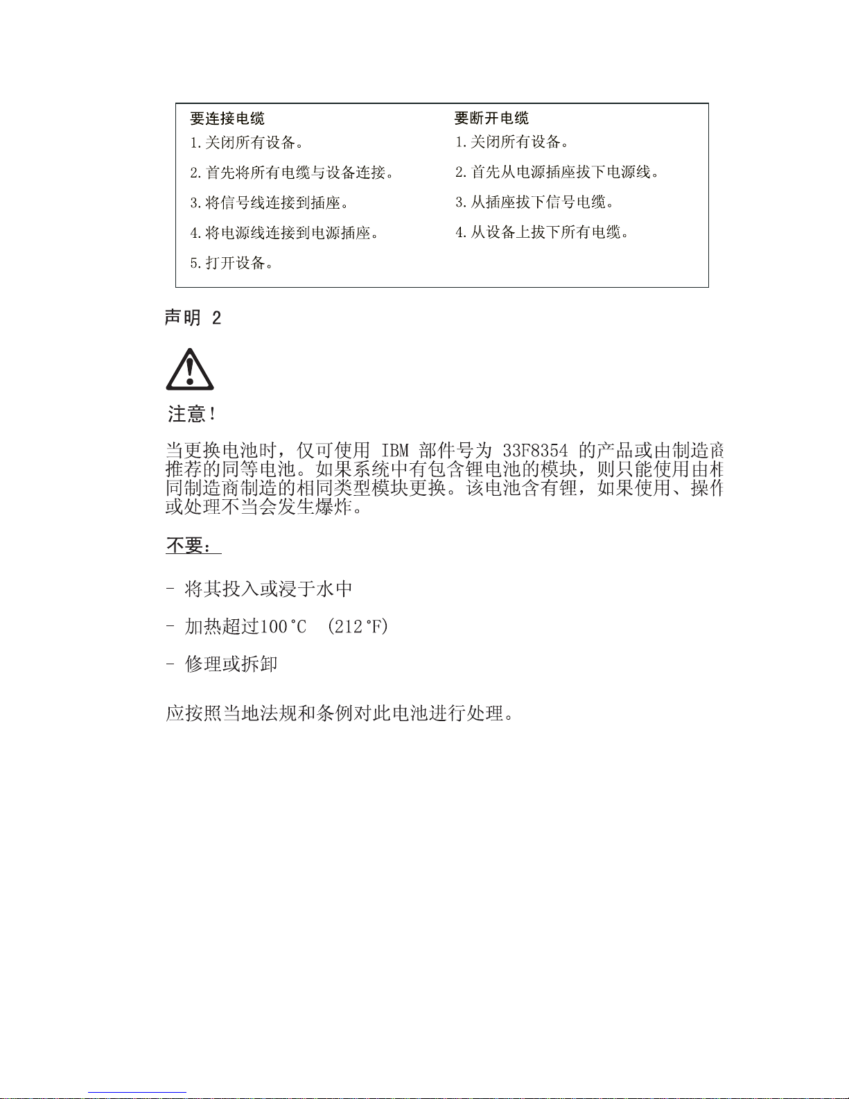
To C o nne ct
1. Turn Everything OFF. 1. Turn Everything OFF.
2. First, attach all cables to devices. 2. First, remove power cord(s) f rom out let
3. Attach signal cables to receptacles. 3. Remove signal cables from receptacles.
4. Attach power cord(s) to outle t. 4. Remove al l cable s from devi ces .
5. Turn devi ce ON
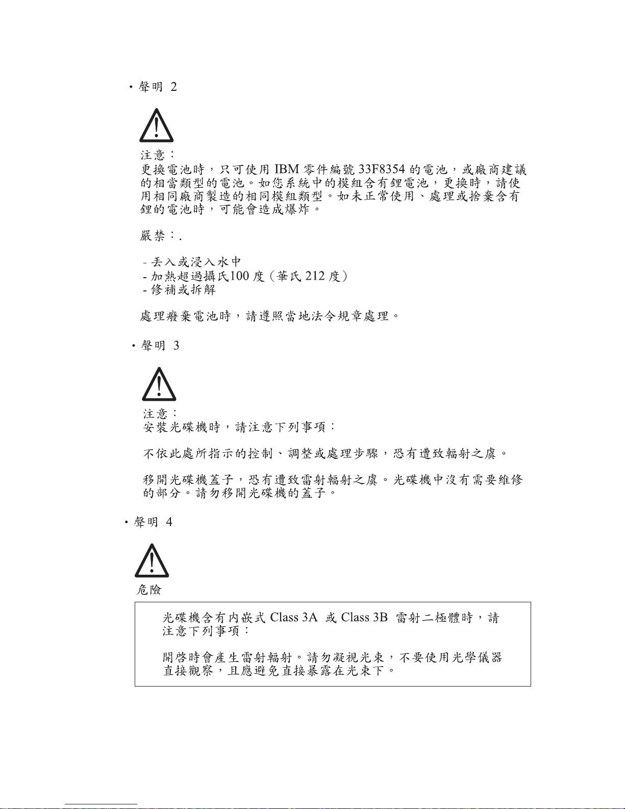
CAUTION:
When replaci ng the batt ery, use only IBM Part Number 33F8354 or
To Disconnect
an equivalent type battery recommended by the manufacturer. If your
system has a module co nta ining a li thium bat tery, replace it only wit h the
same module type made by the same manufacturer. The battery
contains lithium and can explode i f not properly used, handled, or
disposed of.
Do not:
•
Throw or immerse into water
•
Heat to more than 100°C (212°F)
II
Page 9
•
Repair or disassemble
Dispose of the battery as required by local ordinances or regulations.
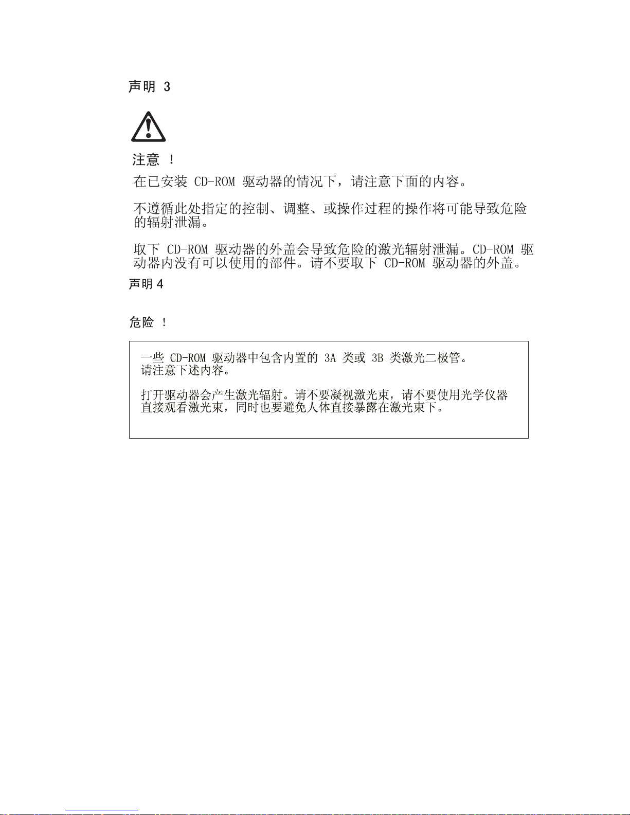
CAUTION:
When a CD-ROM drive is installed, note the following.
Use of controls or adjustments or performance of pr ocedures other than those
specified herein might result in hazardous radiation exposure.
Removing the cover s of t he CD-ROM dri ve could result in exposure to
hazardous las er radiation. There are no serviceab le par ts inside the CD-ROM
drive. Do not remove th e CD-ROM driv e covers.
DANGER
Some CD-ROM drive s conta in an e mbedded Cla ss 3A or Class 3B l aser di ode.
Note the following.
Laser radia ti on when open. Do not stare into the beam, do not view directl y
with optical inst ruments, and avoid di rect exposure to t he beam .
CAUTION:
Electrical current from power, telephone, and communication cables can be
hazardous. To avoid per sonal injury or equipment damage, disconnect the
attached power cords, telecommuni cations systems, networks, and modems
before you open the server covers, unless instructed otherwise in the
installation and configuration procedures.
PERIGO:
Para evita r choques elétricos, não conecte ou desconecte nenhum cabo, nem
efetue instalação, manutenção ou reconf iguração deste produto durante uma
tempestade com raios.
Notices III
Page 10

Para evitar choques elétricos:
•
O cabo de alimentação deve ser conectado a um receptáculo
corretament e instalado e aterrado.
•
Todos os equipamentos aos quai s este produto será conectado devem
também ser conectados a receptácul os corretamente ins talados.
Quando possível, utilize um a das m ãos para conectar ou desconectar cab os
de sinal, para evitar um possível choque ao tocar duas superfícies com
potenciais elétricos diferentes.
A corrente elétrica proveniente de cabos de alim entação, de telefone e de
comunicação é perigosa. Para evit ar choques elétricos, conecte e desconecte
os cabos conforme descrito a seguir, ao instalar, movimentar ou abrir tampa s
deste produto ou de dispositivos conectados.
Para Conectar
1.DESLIGUE tudo.
2.Conecte primeiro todos os cabos nos
dispositivos.
3.Conecte os cabos de sinal nos
receptáculos.
4.Conecte o(s) cabo(s) de alimentação
nas tom a da s.
5.LIGU E o dis p os iti vo
Para Desconectar
1.DESLIGUE tudo.
2.Remova primeiro o(s) cabo(s) de
alimentação das tomadas.
3.Rem ova os cabos de sinal dos
receptáculos.
4.Remov a t od os os cabos dos
dispositivos
CUIDADO:
Ao substituir a bateria, utilize apenas o Número de Peça IBM 33F83 54 ou um
tipo de bateria equivalente recomendado pelo fabricante. Se seu si stema
possuir um módulo com uma bateria de lítio, substitua-o ape nas pelo mesmo
tipo de módulo, produzido pelo mesmo fabricante. A bateria contém lítio e
pode explodir se não for utilizada, manuseada e descartada de forma
adequada.
Não:
•
Jogue ou col oque na água
•
Aqueça a mais de 100°C (212°F)
•
Conserte nem desmonte.
IV
Page 11

Descarte a bateria conforme requerido pelas disposições e regulamentações
locais.
CUIDADO:
Quando uma unidade de CD-ROM estiver instalada, observe o seguinte.
A utilização de controles ou ajustes ou a execução de procedimentos
diferentes daqueles especificados nest a publicação pode resul tar em
exposição per igosa à radiação.
A remoção das tampas da unidade de CD-ROM pode r esultar em exposiçã o a
radiação perigosa de laser. Não existem peças que possam ser consertadas
no interior da unidade de CD-ROM. Não remov a as tampas da unidad e de CDROM.
PERIGO:
Algumas unidade s de CD-ROM contém um diod o de laser da Cla sse 3A ou da
Classe 3B. Observ e o seguinte.
Radiação de las er quando aberto. Não olhe diretamente para o feixe de lase r,
não olhe diretamente com instrumentos óticos, e evite exposição direta ao
raio.
CUIDADO:
A corrente elétrica proveniente de cabos de alim entação, de telefone e de
comunicação é perigosa. Para evitar ferimentos pessoais ou danos aos
equipamentos, desconecte os cab os de alimentação, si stemas de
telecomuni cação, redes e modems antes de abrir as tampas do servi dor, a
menos que receba outras instruções nos procedimentos de instala ção e
configur ação.
Notices V
Page 12
VI
Page 13
Notices VII
Page 14
VIII
Page 15

Notices IX
Page 16
X
Page 17
PERIGO:
Pour éviter tout risque de choc électrique, ne manipul ez aucun câble et
n'effect uez aucune opé rat ion d' inst alla tion, d'entr etien o u de reconfi gu ration de
ce produit au cou rs d' un orage.
Pour éviter tout risque de choc électrique :
•
Les cordons d'alimentation du présent produit et de tous les appareils qui
lui sont connectés doivent être branchés sur des socles de prise d e courant
correctement câblés et mis à la terre.
Afin d'évit er tout risque de choc électrique provenant d'une dif férence de
potentiel de terre, n'utilisez qu'une main, lorsque cela est poss ible, pour
connecter ou déc onnecter les cordons d'interfa ce.
Le courant éle ctr ique passant dans les câbles de communication, ou les
cordons téléphoniques et d'alimentation peut être dangereux . Pour éviter tout
risque de choc électrique, lo rsque vous installez ou que vous déplacez le
présent pr oduit ou des périphériques qui lui sont raccordés, reportez-vous aux
instruc tions ci-dessous pour connecter e t déconnecter les différe nts cordons.
Connexion
1. Mettez les unités hors tension.
2. Commencez par brancher tous les
cordons sur les unités.
3. Branchez les câbles d'interface sur les
prises.
4. Branchez les cordons d'alimentation sur
un socle de prise de co urant.
5. Mettez les unités sous tension.
Déconnexion
1. Mettez les unités hors tension.
2. Comm encez pas débrancher les
cordon s alimentatio n des socles de prise
de courant.
3. Débranchez les câbles d'interface des
prises.
4. Débranchez tous les câbles des
unités.
ATTENTION:
Remplacez la pile usagée par une pile de référence identique exclusive me nt voir la référ ence IBM - ou par une pile équiva lente recommandée par le
Notices XI
Page 18
fabrican t. Si votre système est doté d'un module contenant une pile au lithium,
vous devez le rempl acer uniquement par un module identiqu e, produit par le
même fabricant . La pile contient du lithium et présente donc un risque
d'explosion en cas de mauvaise manipulation ou utilisation.
•
Ne la jetez pas à l'eau.
•
Ne l'exposez pas à une températ ure supérieure à 100°C.
•
Ne cherchez pas à la réparer ou à la démonter.
Pour la mise au rebut, reportez-vous à la r églementation en vigueur.
ATTENTION:
Si une unité de CD-ROM est installée, prenez connaissance des informations
suivantes :
Pour éviter tout risque d'exposition au rayon las er, respectez l es consignes de
réglage et d'util isat ion des commande s, ainsi que les pro cédures décr ites dans
le présent document.
Pour éviter une exposition directe au rayon laser, n'ouvrez pas l'unité de CDROM. V ous n e pou vez eff ectuer aucu ne op ération d e mai nte nance à l 'i ntéri eur.
PERIGO:
Certaines unités de CD-ROM contiennent une diode las er de cl asse 3A ou 3B.
Prenez connais sance des informati ons suivantes :
Rayonnement laser lorsque le carter est ouvert. Évitez de regarder fixem ent le
faisceau ou de l' observer à l'aide d'instruments optiques. Évitez une exposition
directe au rayon.
ATTENTION:
Le courant électrique circulant dans les câbl es de communication et les
cordons téléphoniques et d'alimentation peut être dangereux . Pour votre
sécurité et cel le de l 'équipem ent, avant de ret irer les car ters du serveu r , mett ez
celui-c i hor s tension et déconnectez ses cord ons d'alimentat ion, ainsi que le s
câbles qui le relient aux réseaux, aux systèmes de télécommunication et aux
XII
Page 19
modems (sauf instruction contraire ment ionnée dans les procédures
d'install ation et de configuration)
.
VORSICHT:
Aus Sicherheitsgründen bei Gewitter an diesem Gerät keine Kabel
anschließen oder lösen. Ferner keine Installations-, Wartungs- oder
Rekonfigurationsarbeiten durchführen.
Aus Sicherheitsgründen:
•
Gerät nur an eine Schutzkontaktsteckdose mit ordnun gsgem äß geerdetem
Schutzkontakt anschließen.
•
Alle angeschlossenen Geräte ebenfalls an Schutzkontaktsteckdosen mit
ordnungsgemäß geerdetem Schutzkontakt anschließen.
Signalkabel möglichst einhändig anschließen oder lösen, um einen
Stromschla g durch Berühren von Oberfl ächen mit untersc hiedlichem
elektrischem Potential zu vermeiden.
Elektrische Spannungen von Netz-, Telefon- und Datenübe rt ragungsleitungen
sind gefähr li ch. Um einen Stromschla g zu vermeiden, nur nach den
Anweisungen arbe iten, die für Inst allation, Transport oder Öffnen von
Gehäusen dieses Produkts oder angesc hlossenen Einheiten gelten.
Kabel ansc hlie ße n
1.Alle Geräte ausschalten und
Netzstecker ziehe n.
2.Zuerst alle Kabel an Einheiten
anschließen.
3.Si gnalkabel an Anschlußbuchsen
anschließen.
4.Netzstecker an Steckdose anschließen.
5.G erät einschalten.
Kabel lösen
1.Alle Geräte ausschal ten.
2.Zuerst Netzstecker von Steckdose
lösen.
3.Si gn alkabe l von Anschlußbuch se n
lösen.
4.Alle Kabel von Einheiten lösen.
ACHTUNG:
Notices XIII
Page 20

Eine verbrauchte Batterie nur dur ch eine Batterie mit der IBM Teilenummer
33F8354 oder durch eine vom Hersteller empfohlene Batterie ersetzen. Wenn
Ihr Syste m ein Modul mit einer Lithium -Batterie e nthält, ersetzen Sie es immer
mit dem selben Modul typ vom selben Herstel ler. Die Batterie enthält Lithium
und kann bei unsachgemäßer V erwendung, Handhabung oder Entsorgung
explodieren.
Die Batterie nicht
•
mit Wasser in Berührung bringen.
•
über 100 C erhitzen.
•
reparieren oder zerlegen.
Die örtliche n Bestimmungen für die Ents orgung von Sondermüll beachten.
ACHTUNG:
Wenn ein CD-ROM-Lauf werk installier t i st, beachten Sie folgendes. Steuerund Einstellel em ente sowie Verfahren nur entsprechend den Anweisungen im
vorliegenden Handbuch einsetzen. Andernfalls kann gefährliche
Laserstr ahlung auftreten.
Das Entfernen der Abdeckungen des CD-ROM-Laufwerks kann zu
gefährlicher Laserstr ahlung führen. Es bef inden sich keine Teile inner halb des
CD-ROM-Laufwerk s, di e vom Benutzer gewartet werden müssen. Die
Verkleidung des CD-ROM- Laufwerks nicht öff nen.
VORSICHT:
Manche CD-ROM-Laufwerke enthalten eine eingebaute Laserdiode der
Klasse 3A oder 3B. Die nachfolgend aufgeführten Punkte beachten.
Laserstr ahlung bei geöff neter Tür. Niemals direkt in den Laserstr ahl sehen,
nicht direkt mit optischen Instrumenten betrachten und den Strahlungsbereich
meiden.
XIV
Page 21

ACHTUNG:
An Netz-, Telefon- und Dat enleitungen können gefährliche elektrisch e
Spannungen anli egen. Um eine Gefährdung des Benutzers oder
Beschädigung des Geräts zu vermeide n, ist der Server auszuschalten. Die
Verbindung zu den angeschlossenen Netzkabeln,
Telekommunik ationssystemen, Netzwerken und Mo dem s ist vor dem Öffnen
des Servergehäuses zu unterbre chen (sofern in Instal lations- und
Konfigura ti onsanweisungen nicht anders angegeben)
PERICOLO:
Per evitare il peri colo di scosse elettriche durant e i te mp orali, non collegare o
scollegar e cavi, non effettuare l'i n stallazio ne, la manutenzione o la
riconfigurazione di quest o prodotto.
Per evitare il pericolo di scosse elettriche:
•
collegare il cavo di alimentazi one ad una presa elettrica correttament e
cablata e munita di terra di sicurezza;
•
collegare qualsiasi appare cchiatura collegata a questo prodot to ad una
presa elettri ca correttamente cablata e munit a di te rra di sicurezza.
Quando possibile, collegare o scoll egare i cavi di segnale con una sola mano
per evitare il rischio di scosse derivanti dal contatto con due superfici a di verso
potenziale elettrico.
La corrente elettrica circol ante nei cavi di alimentazione, del telefono e di
segnale è per icol osa. Per evita re scoss e el ettr iche, colle gare e sc ollega re ica vi
come descr itt o quando si ef fett uano l' inst all azi one, l a rimozi one o l'ape rtura dei
coperchi di questo prodotto o dura nte il collegamen to del le unità.
Notices XV
Page 22
Per collegare
1.SPEGNERE tutti i dispositivi.
2.Collegare prima tutti I cavi alle unità.
3.Coll eg ar e i cav i di se gnale all e pr e se .
4.Co llegare il( i) cavo(i) di alimentazi one
alla presa elett rica.
5.ACCENDERE le unità.
Per scollegare
1.SPEG NERE tutti i disp ositivi.
2.Rimuovere prima il(i) cavo(i) di
alimentazione dalla presa elettrica.
3.Rimuovere i cavi di segnale dalle prese.
4.Rimuovere tutti i cavi dall e unità.
ATTENZIONE:
Quando si sosti tui sce la batteria, utilizzare solo una batteria IBM o batterie
dello stesso tipo o di tipo equivalente consigliate dal produttore. Se il sistema
di cui si dispone è pro vvisto di un modulo cont enente una batteria al litio,
sostituire tale batteria solo con un tipo di modulo uguale a quello fornito dal
produttore. La batteria cont iene litio e può esplodere se utilizzata, maneggiata
o smaltita impropriamente.
Evitare di:
•
Gettarla o immergerla in acqua
•
Riscaldarla ad una t em peratura superi ore ai 100°C
•
Cercare di ripar arla o smaltirla
Smaltire secondo la normativa in vigore (D.Lgs 22 del 5/2/97) e successive
disposiz ioni nazionali e loc ali .
XVI
Page 23

ATTENZIONE:
Quando è instal lat a un'unità CD-ROM, not are quanto segue:
L'utili zzo di controlli, regolazioni o l'e secuzione di proced ure non descritti nel
presente manual e possono provocare l'esposizione a radiazioni pericolose.
L'apertura di un'unità CD-ROM può determinare l'esposizione a radia zioni
laser pericolose. All'i nterno dell'unità CD-ROM non vi sono parti su cui
effet tuare l'assistenza tecnica. Non rimuovere i coperchi dell'uni tà CD-ROM.
PERICOLO:
Alcune unità CD-ROM contengono all'interno un diodo laser di Classe 3A o
Classe 3B. Prestare attenzione a quanto segue:
Aprendo l'unit à vengono emesse radiazioni laser. Non fissare il fasci o, non
guardarlo dir ett am ente con strumenti ottici ed evit are l'esposi zione diretta al
fascio.
ATTENZIONE:
La corrente circolante nei cav i di ali m entazione, del tel efono e di segnale è
pericolosa. Per evitare situazioni pericolose per le persone o danneggiamenti
all'apparecchiatura, scollegare i cavi di alimentazione, i sistemi di
telecomunicazioni, le reti e ed i modem prima di aprire i coperchi del servente
se non di versam ente i ndicat o nelle proced ure di i nstal lazi one e co nfi gurazi one.
Notices XVII
Page 24

XVIII
Page 25

Notices XIX
Page 26

XX
Page 27

PELIGRO:
Para evitar u na posible descarga eléctrica , no conecte ni desconecte los
cables ni lleve a cabo ninguna operaci ón de instalación, de mantenimiento o
de reconfiguración de este produc to durante una torment a eléctrica.
Para evitar una posible descarga:
•
El cable de alimentación debe conectar se a un receptáculo con una
instalación eléctrica correcta y con toma de tierra.
•
Los aparatos a los que se conecte este producto también deben est ar
conectados a rece ptáculos con la debida instalación eléctrica.
Cuando sea posibl e, ut ilice una sola mano par a conectar o desconectar los
cables de señal a fin de evitar una posible des carga al tocar dos super ficies
con distinto potencial eléctrico.
La corriente eléctrica de los cables de comunicaciones, teléfono y
alimentación puede resultar pel igrosa. Para evitar una posible descarga, siga
las indic aciones de conexión y desconexión de los cables siempre que tenga
que instalar, mover o abrir las cubiertas de este product o o de los di spositivos
acoplados.
Instrucci one s de conex ió n
1.Ap ague todos los componentes (O FF).
2.En primer lugar, conecte t odos los
cables a los dispositivos.
3.Conecte los cables de señal a los
receptáculos.
4.Co necte los cables de alimentación a
las tom a s.
5.Encienda el dispositivo (ON).
Instrucciones de desconexión
1.Enciend a todos los componentes (ON).
2.En primer lugar, retire los cables de
alimentación de las tomas.
3.Retire los cables de señal de los
receptáculos.
4.Retire todos los cables de los
dispositivos.
Notices XXI
Page 28

CAUTION:
Al cambiar la batería, utilic e únicamente la bater ía I B M Númer o de pieza
33F8354 o un ti po de batería equivalente recomendado por el fabricante. Si el
sistema tiene un m ódulo que contiene una batería de litio , sustitúyalo
únicamente por el mismo tipo de módulo del mismo f abricante. La bat erí a
contiene litio y puede explotar si no se utiliza, manipula o desecha
correcta me nte.
Lo que no debe hacer
•
Tirar o sumergir el producto en agua.
•
Exponer el producto a una temperatura superior a 100°C.
•
Reparar o desmontar el producto.
Cuando quier a desechar la batería, siga las disposiciones y reglamentaciones
locales.
CAUTION:
Cuando instale una unidad de CD-ROM, tenga en cuenta la siguiente
información.
Si se llevan a cabo controles o ajustes o se utilizan métodos que no se
atengan a lo aquí especificado, se puede producir una exp osición peligrosa a
las radiac iones.
Si se retiran las cubiertas de la unidad de CD-RO M , se puede producir una
peligrosa exposición a radiaciones de láser. Dentro de la unidad de CD-ROM
no existen piezas repar ables. No retire l as cubier tas de la uni dad de CD-ROM.
PELIGRO:
Algunas unidades de CD-ROM tienen incorp orado un diodo de láser de Clase
3A o de Clase 3B Tenga en cuenta la siguient e información.
Cuando la unidad está abierta se generan emisiones de rayos láser. No dirija
la mirada al haz, no lo observe directament e con instrumentos ópt icos y evite
la exposición directa.
XXII
Page 29

CAUTION:
La corriente eléctrica de los cables de comunicaciones, de teléfono y de
alimentación puede resultar pel igrosa. Para evitar posibles lesiones o daños
del aparato, desconecte los cables de alimentac ión, los sistemas de
telecomunicaciones, las redes y los módems antes de abrir las cubiertas del
servidor, salvo que se indique lo contrario en las instrucciones de las
operaciones de inst alación y conf iguración.
Notices XXIII
Page 30

Laser Compliance Statement
The CD/DVD-ROM drive in the comput er i s a laser product. The CD/DVDROM drive's classification label (sample shown below) is located on th e dri ve.
CLASS 1 LASER PRODUCT
APPAREIL A LASER CLASSE 1
LASER KLASSE 1
LUOKAN 1 LASERLAITE
PRODUIT LASER
CATEGORIE 1
The CD/DVD-ROM drive is certified in the U.S. to conform to the r equirements
of the Department of Health and Human Services 21 Code of Federal
Regulations (DHHS 21 CFR) Subch apter J for Class 1 laser products.
In other countries, the drive is certified to conform to the requirements of
EN60825.
Class 1 l aser pr oducts are not co nsider ed to be haz ardous. The CD/DVD- ROM
drive has an internal Class 1, 0.5-milliwatt, aluminum gallium-arsenide laser
that operates at a wavelength of 760 to 810 manomet ers.
The design of the las er system and t he CD/DVD-ROM drive ensur es that there
is no exposure to laser radiation above a Class 1 level during normal
operatio n, user maintenance, or servicing conditions.
XXIV
Page 31

Trademarks
The following ar e tra dem arks of the IBM Corporation in th e Unit ed States or
other countries or both:
Aptiva
AT
HelpCenter
IBM
Operating Sys tem/2
OS/2
Personal System /2
PS/1
PS/2
Intel, Pent ium, MMX, EtherExpress, and LANDesk are trademarks or
registered trademarks of Intel Corporation.
Microsoft, MS-DOS, Windows, and Wind ows NT are tr adem arks or regist ered
trademarks of Microsoft Corporation.
Other company, product, and service names may be trademarks or service
marks of others.
Notices XXV
Page 32

Preface
This manual contains service information for the
(SL-A)
intended to be used as a stand-alone document to service Apt iva machine type
2158/2163 products. It is divided into the followi ng chapters:
Notices
this computer.
General Information
Check Procedures
failing Field Replaceable Unit (FRU).
Diagnostic Aids
failures.
Repairing Information
and reassemble t he com puter.
Parts/Test Point Locations
locatio ns of the major parts, jumpers, and conne ctors .
Safety Inspecti on Guide
safety prob lems before putting the machine under a Maintenance Agreement.
model of the IB M Apti va Personal Computer , worldwide. This manual is
contains imp ortant safety information and notices required to se rvi ce
contains a brief description of this manual.
provides step-by-step instructions that aid in locating the
explains how to use the diagnostics tools for isolating
contains illustrations and descr iptions to disassemble
contains illustrations and descriptions of the
contains info rmat ion about inspec ting a machi ne for
2158/2163 Service Level A
Parts Catalog
individual FRUs.
Appendix A, FRU Number Index
order.
Appendix B, Online Support Information
information.
Appendix C, Model/Monitor Configurations and FRU Part Numbers
contains model s and FRUs listed by part numb er fo r all countries.
contains desc ri ptions, illustration s, and part numbers for
contains part numbers listed in numerical
contains online support
XXVI
Page 33

General Info rmation
Introduction ......................................................................................................2
Produ ct Over v ie w ....... ........ .. ....... ........ ....... ....... ... ....... ....... ........ .. ....... ........ .....2
Processors (Machine Type 2158) ..............................................................2
Processors (Machine Type 2163) ..............................................................2
Memory......................................................................................................3
Exte rn a l P o rts.......... ....... .. ........ ....... ....... ........ .. ....... ........ ....... .. ........ ....... ...3
Disk e tte D ri ve....... ........ .. ....... ........ ....... .. ........ ....... ....... ........ .. ....... ........ .....4
Hard D is k D rive.... ... .. ....... ........ ....... ... ....... ....... ....... ........ .. ....... ........ ....... .. .4
CD/ DV D -R O M D rive ...... .. ........ ....... ....... ........ .. ....... ........ ....... .. ........ ....... ...4
Mult ime d ia............ ........ ....... .. ........ ....... ....... ... ....... ....... ........ ....... .. ........ .....4
Power Management ...................... ............................................................. 4
Powe r S up p ly.. ........ ....... ....... ... ....... ....... ........ ....... .. ........ ....... ....... ... ....... ...4
Internal Cabling..........................................................................................5
Modem................................ .................................................................. .....5
Monitor (Not included with some models)..................... ........ ......... ........ ....5
Keyboard....................................................................................................6
Mouse ........................................................................................................6
Hardw a re Inter fa ces ........ ....... ........ .. ........ ....... ....... ....... ... ....... ....... ........ .. ....... .6
CMOS Reset ....................................................................................................7
Power-On Password ........................................................................................8
Flash (BIOS) Update Procedure ....... ........ .. .. ........ .. ........ .. ........ .. .. ........ .. .........9
BIOS-contained Model Number and Serial Number ...................................... 10
BIOS Setup Utility ..........................................................................................11
Working with the Setup Menus ................................................................11
Viewing System Information, Video Information and Model Information.. 13
Disk Drives...............................................................................................14
Input/Output Ports........................................................... .........................16
Power Management ...................... ...........................................................17
Startup Options........................................................................................18
Advanced Options....................................................................................19
Spec ificat ions . ....... ........ ..... ....... ....... ..... ....... ........ ....... ..... ....... ....... ..... ........ ... 2 3
Dimension (width x depth x height)..........................................................23
Weight......................................................................................................23
Environment.............................................................................................23
Powe r co n sump tio n . ....... ....... ........ .. ....... ........ ....... ....... ... ....... ....... ........ .. .23
Electrical input..........................................................................................24
Operating Requirements ............ ........ ......... ........ ......... ........ ......... ........ .........24
Special Tools .................................................................................................24
Copyright IBM Corp. 1998 1
Page 34

Introduction
This chapter gives a general overview of the Aptiva Machin e Type 2158/2163,
describes the standard and optio nal features, and detai ls functiona l and
environmental specifications.
Product Overview
Machine Type 2158 and 2163 bot h h ave two PCI sl ots a nd one PCI/I SA shared
slot. The 2158 system supports the AMD K6 processor family while t he 2163
supports the Pentium II and Celeron processors.
Both 2158 and 2163 support Accelerated Graphics Port (AGP), which allows
all installed system memory to be used as texture memory, yielding a huge
texture footprint to enhance 3D graphical display performance.
Listed below are 2158 and 2163 system features:
Processors (M achine Ty p e 2158)
•
Socket-7 Zero Insertion Force (ZIF) connector.
•
Detachable CPU heat sink with fan.
•
One of the following processors can be i nstalled:
- AMD K6-2/333 processor; 95MHz external, 333 MHz inter nal, with
™
3DNow!
- AMD K6-2/350 processor; 100MHz external, 350 MHz internal, with
3DNow!
technology
™
technology
Processors (M achine Ty p e 2163)
Pentium II
•
Processor with the capabilities of MMX™ tech nology
•
Processor in Single Edge Contact (S.E.C.) cartridge packaging technology
(slot 1).
•
Dual Independent Bus architectur e separates dedicated external system
bus and dedicated internal high-speed cache bus.
•
One of the following processors can be i nstalled:
- Intel Pentium II -350 MHz internal, 100 MHz external
- Intel Pentium II -400 MHz internal, 100 MHz external
- Intel Pentium II -450 MHz internal, 100 MHz external
2
Page 35

Celeron
•
Includes Intel MMX™ media enhancement technology.
•
Offers Dynami c Execution technology.
•
Processor is provide d in the Single Edge Processor Package (S.E.P.P.) with
out L2 cache and fits int o the slot 1.
•
One of the following processors can be i nstalled:
- Celeron 366 Mendocino
- Celeron 400 Mendocino
Memory
•
512-KB Pipeline Burst Static RAM (PBSRAM). Fixed onboard for 2158,
built-in Pent ium II and Celeron processors for 2163.
•
8-MB video Sy nchronize D-RAM (SDRAM). Fixed onboard for 2158, bui lt -in
AGP video adapter car d for 2163.
•
168-pin Synchronous Dynamic Random Access Memory (SDRAM), Dualin-line Memory Mo dule (DIMM) sockets.
- 2 memory socket s for 2158, 3 sockets for 2163.
- 16-MB, 32-MB, 64-M B or 128-MB DIMM.
- PC-100 (64-bit, non-ECC, 100MHz, 3.3vol t) DIMMs with gold contact s
- For 2158, maximum m emory is 256 MB, for 2163 is 384 MB.
External Ports
•
Video port (15- pin D-sub connector)
•
Parallel por t (25-pin D-sub connector)
•
Serial port (9 -pin D-s ub connect or). 2158 has on e serial por t whil e 2163 ha s
two.
•
Game/MIDI port (1 5-pin D-sub connector)
•
Keyboard port (6-pin PS/2 mini-din connector)
•
Mouse port (6-pin PS/2 mini-din conne ctor)
•
Two USB ports
•
Microphone-i n jack
•
Speaker-out jack
•
Line-in jack
Diskette Drive
•
AT-type
General Inform ation 3
Page 36

•
3.5-in. 1.44 MB slimline diskette drive.
Hard Disk Drive
•
3.5-in., 1-in. height or 5.25-in, 1-in. height IDE AT drive. (3.5 -in may be in
acoustic mount ing bracket)
•
128 KB “look-ahead ” cache memory in hard disk dr ive.
•
Average and minim um 12 ms seek t i me, acces s t ime var ies fo r the hard disk
drive and the hard disk drive manufacturer.
CD/DVD-ROM Drive
•
5.25-in. high -performance, 32X CD-ROM or 4X DVD-ROM IDE/AT drive.
•
Read data and play audio from standard and mini CD-ROM and audi o
compact discs (audio CDs). DVD media suppor ted on DVD models.
Multimedia
•
A pair of external acti ve speakers with power adapter for 2158 or passive
speakers for 2163.
•
Noise canceling microphone (available on certain models)
Power Management
•
Compliant to ACPI and supports Display Power Management Signaling
(DPMS) monitor.
•
Software shutdown by Windows 98.
•
System enters st andby mode if any of followi ng conditions are met:
- Execute st andby from Windows 98 Start menu
- Press syst em power butt on if it sets to act as s tandby funct ion. See “ Power
Management ” on page 4.
- System is idle and the standby timer set i n the Windows 98 Power Management Property elapses.
Power Supply
•
PC-98 compatible 95W ATX power supply
•
Searchable high/low voltage selection
Internal Cabling
•
Two 40-pin ribbon cables for hard disk drive and CD/DVD-ROM drive.
•
One 34-pin ribbon cable for AT diskette drive.
•
One 4-pin (2-wire) cable for hard disk dr ive light-emitting diode (LED).
4
Page 37

•
One 3-pin (3-wire) cable for power li ght-emitting di ode (LED).
•
One 2-pin (2-wire) cable for power switch.
•
One 4-pin modem voice-in/speaker-out cable.
Modem
•
56.6 Kbps PCI modem adapter car d wit h data/fax/voice or non-voice
features.
•
Telephone line-out (RJ-11) connector.
•
Telephone line-in (RJ-11) connector.
Monitor (Not included with some models)
•
Super Video Grap hics Array (SVGA) monitor.
•
Compliant to VESA power saving mode.
•
Connector for a detachable grounded 3-wire power cord
•
1.8-m (5.8-ft.) attached signal cable
•
Auto-sensing power input for 100 Vac to 240 Vac
•
15" (13.7" viewable image size) monitor
- 0.28-mm dot pit ch
- Automatic scanning horizont al frequencies from 30 KHz to 54 KHz or 30
KHz to 69 KHz (for Japan)
- Vertica l fr equencies between 50 Hz and 120 Hz.
- DDC2A/B or DDC1/2B+ support (for Japan)
- OSD (On-Screen Dis play) menu (for Japan)
•
17" (15.7" viewable image size) monitor
- 0.28-mm or 0.27-mm dot pitch (for Japan)
- Automatic scanning horizont al frequencies from 30 KHz to 69 KHz or 30
KHz to 72 KHz (for Japan)
- Vertica l fr equencies between 50 Hz and 120 Hz.
- DDC1/2B+ support and OSD (On-Screen Display) menu
Keyboard
•
104-key, 105-key or 109-key rubber dome Rapid Access™ keyboard with
1.8- m (5 .8 - ft.) cab le
•
PC Next keyboard (for Brazil)
General Inform ation 5
Page 38

Mouse
•
2 button PS/2 sleek or Scroll Point™ mouse with 1.8-m (5.8-ft.) cable
Hardware Interfaces
The following peripheral interfaces for adapters, options, and drives are
supported in the system unit.
Item- Interface
Expansion slot for I/O
adapter cards
Hard disk drives Two PCI local bus Enhanced IDE v1.0 compatible hard disk
CD/DVD-ROM drive 5.25-in. high-performance, 32X CD-ROM or 4X DVD-ROM
Diskette drive AT diskette interface
Video Physical interfa c e is compatible with the IBM P ersonal
Machine Type 2158 and 2163
Three PCI (Peripheral Component Interconnect) v2.1
compatible expansion slots that operates at 33 MHz bu s
speed.
One I BM AT-ISA Pl ug an d Pl ay co mpa tib le ex pa nsi o n s lo t th at
operates at 8 MHz bus speed.
Note: There is 1 PCI/ISA shared slot
drive inte rfaces that support:
- PIO mode up to mode 5
- DMA 32-bit access up to mode 2
- Ultr a 33 Synch ronous DMA up to mo de 2 (33M bytes/ sec.).
IDE/ AT drive.
Support Bootable C D-ROM Format specification version 1.0.
Compliant to Audio-CD, Video-CD, CD-ROM/XA, Karaoke-
CD, and Pho t o -C D (bot h single an d mu lti-ses sion) f orm at .
System/2 (PS/2) VGA interface.
Support Accelerated Graphics Port (AGP)
Modem One 56.6 Kbps PCI modem adapter card with data/fax/voice
Audio Compatible to Sound Blast er, Sound Blaster Pro and
Pointing device IBM PS/2-compatible mouse
Keyboard device IBM PS/2-compatible keyboard
Seri al port Suppor ts high speed 16450/16550 compatible U ARTs with
6
or non-voic e features.
Windows Sound System
send/receive 16 bytes FIFOs
RS232D electrical interface compliant
Page 39

Item- Interface
Parallel port Supports SPP (IBM PC/XT, PC/AT, PS/2) compatible, EPP
(IEEE 1284 compliance), ECP (IEEE 1284 compliance)
interface.
IEEE 1284 compliant
Game port Game port interface for joystick. It also supports MIDI.
USB Suppor ts Universa l HCI Specification for USB 1.0
CMOS Reset
This system does not deny access to BIOS Setup Util ity. Execute “Load BIOS
Default Settings” in BIOS Setup to clear the corrupted CMOS data. See
“Loading the Defaul t Settings” on page 12.
General Inform ation 7
Page 40

Power-On Password
A power-on passwor d denies access to the system by an unauthorized user
when the system is powered on. When a power-on passwo rd i s acti ve, the
password prompt appears on the screen each time the system is power ed on.
The system start s after the proper password is entered. See “Power-on
Password” on page 19 for more information about how to change, remove and
set password in BIOS Setup.
In some cases, you might be required to service a system with an active and
unknown power-on password. To clear a password fr om the system, follow
these steps.
1. Turn off system un it .
2. Unplug power cable from the electrical outlet.
WARNING:
electrical outlet. The power supply m aintains +5 Vdc of standby power
when the power cord is plugged. System damage mi ght result if the
power cord is not unplugged during testing.
Machine Type 2158:
password check process. See “Machi ne Type 2158 System Board Jumpers
and Connectors” on page 107.
Machine Type 2163:
password check process. See “Machi ne Type 2163 System Board Jumpers
and Connectors” on page 111.
3. Plug power cable, tu rn on the syst em, and dep res s F1 duri ng POST t o enter
BIOS Setup menu.
4. Select “Advanced Options”, then enter “Security Options” and set “Power
On Password” setting to “None” to clear password.
5. Save and exit from BIOS Setup.
6. Turn off the system, unplug power cable from electrical outlet.
Machine Type 2158:
password check process. See “Machi ne Type 2163 System Board Jumpers
and Connectors” on page 111.
Do not attempt these steps with the power cord plu gged into the
Set switch 2 of SW2 to the OFF position to bypass
Set switch 5 of SW1 to the ON position to bypass
Set switch 2 of SW2 to the ON position to enable
Machine Type 2163:
password check process. See “Power Supply Connectors and Voltages” on
page 114.
IMPORTANT:
Setup Utility.
8
To reinstall the password, the user must enter a password in the
Set switch 5 of SW1 to the OFF position to enable
Page 41

Flash (BIOS) Update Procedure
NOTE:
1. Prepare a bootable DOS diskette disk with AFLASH.EXE, MSG.DAT,
NOTE:
2. Insert the diskette and boot from drive A.
WARNING:
3. At the DOS prompt, type A:> AFLASH VXXYYZZ.BIN then press Enter.
4. The program updates the BIOS automatically.
IMPORTANT: :
5. Wait f or the update to complet e (indicated by the beeps).
WARNING: :
6. Power off system after the BIOS is compl etely updated.
The flash update procedure does not change the model number and
serial number information in BIOS.
VXXYYZZ.RN and VXXYYZZ. BIN files
The AFLASH.EXE and MSG.DAT are flash utility programs. The
VXXYYZZ.RN file has the BIOS checksum information. The
VXXYYZZ.BIN is BIOS source code binary file.
Do not boot with any memory related driver su ch as HIMEM.SYS,
EMS.SYS....
V erify the BIOS checksu m value shown on screen is the same
as the one in VXXYYZZ.RN fi le.
Do not tu rn of f t he system power w hile t he BIOS i s prog rammi ng,
or the flash ROM will be destro yed.
General Inform ation 9
Page 42

BIOS-contained Model Number and Serial Number
The model number and seri al number information is stored in BIOS ROM and
displayed in the “Model Information” of BIOS Setup main menu. If a service
repair is completed by replacing a new system board or a new BIOS ROM,
then you are requi red to input the ori ginal system's model number and serial
number into t he new BIOS ROM.
Follow these steps to input the model numb er and serial number to BIO S:
1. Prepare a bootable DOS diskette with CHGDMI.EXE and MODEL.DMI
files.
2. Insert the diskette and boot from drive A.
WARNING:
EMS.SYS....
3. At the DOS prompt , type A: >CHGDMI/W t hen press Ent er. When the screen
shows:
System Product Name:
Enter the mod el number and p ress Ent er to c ont inue. You can t ype a maxi mum
of 16 char acters (without spaces).
4. When the screen shows:
System Serial Number:
Enter the serial number and press Enter to cont inue. You can type a maximum
of 16 char acters (without spaces).
5. Type A:>CHGDMI/D and press Enter to display and verif y your input model
number and serial number information.
Do not boot with any memory related driver su ch as HIMEM.SYS,
10
Page 43

BIOS Setup Utility
The Setup Utilit y lets you review and change important info rmation about the
computer and its hardware.
Working with the Setup Menus
Starting the Setup Utility
Follow these steps to ent er Setup when the computer is off:
1. Turn on your monitor.
2. Turn on the system unit.
3. When you see the IBM Aptiva logo, press F1 to enter Set up and display the
Main Menu.
If you have previously set a power-on password, you are prompted to type in
the password after you press the F1 key. See “Power-on Password” on page
19 for informati on on setting, changing, or removing the password.
Refer to the Setup Utility Main Menu below.
General Inform ation 11
Page 44

The following table lists speci fi c keys on the keyboard that will help you move
through the Setup m enus:
Keys Function
Down- or up-arrow key Use these arrow keys to highlight an option on the
menu. (Press the Enter key to choose the option.)
Left- or right-ar row key Use these arrow key s to make a selection and change
an option's setting. On some menus, you can use these
key s to move from one field to another.
PgUp Press this key to move from a menu to the menu
imm ediately preceding it. This key works only in
options with multiple menus.
PgDn Press this key to move from a menu to the menu
imm ediately following it. This k ey works only in opti ons
with multiple menus.
F1 Press this key if you want help f or a selected menu
option.
Esc Aft er viewing or making changes to the s ettings on a
menu, press this key to exit the menu.
Enter Press this key to choose a highlighted option from a
menu
Changing Parameter Settings
In the Setup menus, the conf iguration information that you can change is
enclosed in brackets like these: [ ]. You cannot change any information that is
not enclosed in brackets. Use the up- or down- arrow keys to highl ight options
then press Ente r to display a menu. When changing the setting of a par ti cular
parameter, highlight the sett ing then use the left- or right- arrow key to change
the setting.
Loading the Default Settings
When you purchase an Aptiva computer, it is already configur ed for use. The
original configuration settings, also called factory or default settings, are stored
in the CMOS. Setup includes an option Load Default Settings that lets you
reload the original configuration at any time.
12
Page 45

If you have made changes in Setup but would like to restore the default
settings, follow these steps:
1. Press F5 to load default settings. A dialog box appears confi rming if you
want to load the defaul t settings.
2. Use the left-arr ow key to select Yes, then press Enter.
3. Press Esc to exit Setup.
A dialog box appears confirming if you want to save the CMOS settings (i n
this case, the default settings that you reloaded).
4. Use the left- arrow key to sel ect Yes, then pr ess Ent er to s ave the chan ges i n
CMOS.
You must load the Setup default set tings in the foll owing instances:
•
When you replace the system battery
•
When you cust omize your sys tem co nfigur ation setti ngs and some resou rce
assignments conflict cau sing the computer to hang
Exiting Setup
When you complete your changes or finish viewing information, return to the
main menu. From this location, you can exit Setup and save your changes or
exit without saving your changes.
Follow these steps to exit Setup:
1. From the main menu, press the Esc key.
2. The Exit Setup dialog box appears. If you have m ade changes in the
parameter settings, it will contain an option for saving your changes.
- If you would like to save your changes, press the left-arrow key to select
the option Yes then press Enter to save you r changes and exit Setup.
- If you do not want t o save your c hanges, pres s the rig ht-arrow k ey to sele ct
the option No then press Enter, to exit Set up wit hout saving.
Viewing System Information, Video Information and Model
Information
To view general hardware informati on about your computer, select the System
Information option from the Setup ma in menu. The items displ ayed in the
System Infor ma ti on m enu are not configur able.
Setup automatically updates this menu when you do either of the following:
•
Add or change hardware on your computer
•
Make changes to other menus in Setup and save those changes
General Inform ation 13
Page 46

To view the video informat ion such as the video controller and video memory,
select the video information option from the setup menu.
Select primary display adapter to initialize onboard VGA as the boot display
device. Select Auto to initial ize PCI add-on VGA card as the boot display
device if a PCI add-on card is found; otherwis e, onboard VGA will be initial ized.
To view the computer information such as the model num ber, serial number,
and BIOS versi on and d ate, sele ct the Model Infor mation opt ion from the Set up
main menu. Like in the Syst em Information menu, the items displayed are not
configur able.
Disk Drives
If you install a new diskette, hard disk, or CD/DVD-ROM driv e, BIOS autodetects the pres ence of these dev ices. Enter Setu p to ident ify or verif y the typ e
of drive installed in the computer.
If you want to chang e any drive setti ng, sel ect Di sk Dri ves fr om the main me nu.
The Disk Drives menu appears showing the diskette drive and IDE dr ive
parameters.
Diskette Drive A
This option displays the size and stor age capacity of the currently i nstalled
diskette drive. Empty drive bays are indicated wi th a “None” setting.
LS-120 Drive As
This option all ows user to set for the LS-120 drive. Empty drive bays are
indicated with a “Normal” setting. Its possible settings are:
Normal
removal media.
Drive A
standard di skette drive A exists , system automatically identif ies it as drive B.
Drive B
ATTENTI ON:
The LS-120 drive is configured by Windows 98 and acts as an ATAPI
System recognizes the LS-120 drive as drive number 0 (drive A). If a
System recognizes the LS-120 drive as drive B.
If “Boot Sequence” in “Startup Opt ions” is set to CD-ROM and a
bootable CD is loaded, BIOS identifies LS-120 (original set as drive A)
as drive B and the standard diskette drive becomes inaccessible.
IDE Hard Disk and CD/DVD-ROM Drives
The Disk Drives menu inclu des four IDE drive it ems that al low you to configur e
the hard disk drives and the CD/DVD-ROM drive. Selecting any one of these
items displays a submenu with detail s on a particular IDE dri ve.
The IDE drive items are identified as follows:
14
Page 47

•
IDE Primary Channel Master is attached to IDE connector 1 on the system
board and i s set as the master device. This is the har d disk that comes
preinstall ed with your computer.
•
IDE Primary Channel Slave (if installed) is attached t o IDE connector 1 on
the system board and is set as the slave device.
•
IDE Secondary Channel Master (if instal led) is attached to IDE connector 2
on the system board and is set as the master devic e.
•
IDE Secondary Channel Slave (if installed) is attached to IDE connector 2
on the syste m b oard and is set as the slave device. Nor m all y, a prei nstalled
CD/DVD-ROM drive is connect ed here.
NOTE:
Proceed to the foll owing for details on t he parameters under each IDE drive
submenu.
Type
size of a particular IDE drive. If no inf ormation appears opposite the
parameters, there is no drive inst alled in that channel.
Hard Disk Block Mode
on the har d disk in us e. BIOS automatically detects if your hard disk supports
this featur e.
Setting to Auto allows data transfer in blocks (multiple sectors) to increase the
data transfer rate. If your system does not boot after setting this parameter to
Auto, change th e sett ing to Disabled. The default setting for this parameter is
Auto.
Advanced PIO Mode
performance by allowing the use of faster hard disk drives. I f your hard disk
supports th is feature, you may set thi s parameter to Auto (default), Mode 0,
Mode 1, Mode 2, Mode 3, or Mode 4 depen ding on th e hard disk req uirement s.
See the documentation that came with the hard disk.
The CD/DVD-ROM drive inf ormation does not appear among these
options. Cli ck on the System Informat ion option i n the Setup main menu
to verify the presence of a CD/DVD-ROM drive.
This it em specif ie s the number of cyli nder s, heads, and sec tors, and the
This func ti on enhances disk perform ance depending
The advanced PIO mode feature improves syst em
If your hard disk does not support this function, set thi s parameter to Disabled.
Hard Disk Size > 528MB
and Windows environments. If set to Aut o, which is the default, BIOS allows
you to use a hard disk with a capacity of more than 528 MB. This is made
possible through the Logical Block Address (LBA) mode translation. You may
be required to set t his parameter to Disabled if you use other operating
systems.
This enhanced I D E feat ure works only under DOS
General Inform ation 15
Page 48

To prevent data loss, set this parameter to Auto if you are using a hard disk
with more than 528 MB capacity that was previ ously configur ed through the
LBA mode. If you use a hard disk configured throu gh the user-specific cylinde rhead-sector (CHS) mode , set this parameter to Disabled.
Hard Disk 32-bi t Access
performance by allowi ng the use of the 32-bi t hard disk acce ss. This enhanc ed
IDE feature only works under Windows 3.x, OS/2, Windows 95, Windows 98,
and Novell NetWare. If your software does not supp ort this function, set this
parameter to Disabl ed. The default setting is Enabled.
Setting this parameter to Enabled improves syst em
Input/Output Ports
From the Setup main menu, select the Input/O utput Ports option to view or
change port conf iguration settings. The Input/Output Ports menu appears.
This menu lets you confi gure serial and parallel ports .
Also included in this menu are items for enabling or disabli ng the onboard
controller chipsets.
Serial Po rt
Your computer comes with a 9-pin serial port. This parameter display s the
current a ddress f or ser ial por t. Th e def ault s etting Bas e Addr ess is 2 F8 and the
default IRQ is 3.
Parallel Port
Your computer comes wit h one parallel port. This parameter shows the default
Enabled to activate the parallel port. The def ault base address is 378h and the
default IRQ is 7.
The default mode is ECP. The def ault DMA is 3.
Onboard PS/2 Mouse (IRQ12)
This parameter enables or disables the onboard PS/2 mouse. When set to
Enabled, it allows you to use the onboard PS/2 mouse. When set to Disabled,
it deactivates the mouse and frees I RQ 12 for the use of other devices (f or
2163).
Onboard USB
This paramet er allows you to enable or disabl e the Universal Serial Bus (USB)
controller. The default setting is Enabled.
USB Legacy Mode
keyboard outs ide of Windows. The default is Disabled.
This paramete r enables or disables the use of a USB
16
Page 49

Onboa rd Audio Chi p
This parameter enables or disables the onboard audio controller chipset. This
item does not appea r in t he me nu if there is no physical audio chipset on the
system board. The default setting is Enabled.
Power Management
The system power managem ent features allow you to reduce power
consumption.
NOTE:
These Power Management settings do not work in Windows 98. Use
the Control Panel Power uti li ty for Windows 98 Power Management
settings.
Power Manag em ent M ode
When the Power Management Mo de parameter is set to Enab led, you can
configur e the di ff erent power savin g timer s to y our desir ed se tti ngs. Set ting this
parameter to Disabled deactivates the power management feature and al l the
timers. The default setting is Enabled.
IDE hard disk standby timer
standby mode after inactivity of 1 to 15 minutes, depending on your setting.
When you acce ss the hard disk again, allow 3 to 5 seconds (depending on the
hard disk) for th e system to recover and ret urn to normal speed. Set thi s
parameter to Off if your hard disk does not support this function. The default
setting is Off.
System sleep timer
minutes) b efo re the syst em en ter s the s leep st at e. Use t he a rrow key s t o se lect
a setting. You can turn this ti m er to Off if you prefer. The default setting is 60
minutes.
This timer allows you to set the period of inactivity (in
This parameter allows the hard disk to enter
Stop CPU clock in sleep state
stops, along with other internal devices, when the computer enters the sleep
state. When set to No, th e system internal clock continues to run when the
system is in the sleep state. This item turns gr ay and is non-configurable when
the System Sleep Timer is off. The default setting is Yes.
Power Switch< 4 sec.
suspend function to the system power button on the front panel. The suspend
functio n allows you to put the syst em int o suspend mode by pressing the
power button for less th an four seconds while the system is on. When this
parameter is set to Power off, the power button simply turns the system power
on or off. This parameter is set to Power off by default.
When set to Yes, the system int ernal clock
When set to Suspend, this parameter adds the
General Inform ation 17
Page 50

Modem Wake-Up on Ring
the Modem Wake-Up on Ring feature. When enabled and if the computer is in
suspend, an incoming call automatically resumes normal power on mode.
When disabled, the system does not retur n to th e “Normal on” state even if
there is an incoming modem access. The default setting is Enabl ed.
This paramet er allows you to enabl e or di sable
Startup Options
From the Setup main menu, select Startup Opt ions to view or change start-up
configur ation settin gs.
Fast POST Mode
allows the system to boot faster by sk ipping some power on self-test (POST)
routines.
Silent Boot
When set to Enabled, which is the default, BIO S is in graphical mode and
displays the IBM logo while booting. If an error occurs whi le boot ing, the
system automatically switches to text mode.
Even if your setti ng is Enabled, you may also switch to the text mode while
booting by pre ssing F9 after you see the message “Press <F1> to go to the
Setup Utility”.
When set to Disabled, BIOS is in the conventional text mode where you see
the system initialization details on the screen
Num Lock After Boot
functio n on the keyboard turns on automatically each time you turn your
computer on. You can set this to Enabl ed or Disabled. The default is Enabled.
Boot Sequence
Hard Disk or CD-ROM drive.
When set to Auto, which is the default, this parameter
This parameter enables or disables the silent boot function.
This parameter displays whether the NumLock
This parameter allows you to set system boots from Floppy,
Date an d Ti m e
From the Setup main menu, selec t the Date and T ime opti on to vie w or change
the system clock from the Date and Time menu. If you want to change the
system date, enter the date in the format shown on the screen as in the
following example:
Mon Nov 10, 1998
If you change the time, enter the time in 24-hour format (hours, minutes,
seconds). For example:
- 12 midnight is 00:00:00
- 12 noon is 12:00:00
- 1 p.m. is 13:00:00
18
Page 51

When setting dat e and ti m e, press the up- or down- arrow key to highlight a
field. Press the left or right-arrow key to change the settings.
Advanced Options
From the Setup main menu, select the Advanced Opti ons option to view or
change a variety of configuration settings. The Advanced Options menu
appears, with the following opti ons:
•
Security Options
•
Memory/Cache Options
•
PnP/PCI Options
Each of these options opens an additional menu.
Security Options
Power-on Password
Select this parameter and press the left- or right arrow key to display the
Power-on Password window. In this window, you can set up a passwor d to
restrict t he use of your computer. You can also change or remove the
password.
If you set up a power on pass word, you must ty pe this pa sswor d each time yo u
turn on your comput er. If you do not key in the correct password, you cannot
use your computer. You must also ty pe thi s password if you want to enter
Setup.
Setting a Power-On Password
1. Enter Setup.
2. From the Setup main menu, select Advanced Options, then Securi ty
Options.
3. Highlight the Power-on Password par ameter and press the left- or rightarrow key to display the Power-on Password window.
4. Type a password consisting of up to seven characters, then pres s Enter.
5. Retype the password then press Enter.
6. Press Enter again to confirm setting the password. Pr essing Esc aborts t he
password sett ing.
After pressing Enter, the Power-on Password window di sappears. The
Power-on Password parameter automatically set s to Present.
7. Press Esc to return to Setup main menu.
8. Press Esc to exit Setup and reboot the system . Answer Yes when prompted
to save settings.
General Inform ation 19
Page 52

The next time you t urn on the system, you will be prompted to enter your
power-on pass word. I f you pr ess F1 durin g POST t o enter Se tup, y ou must key
in the password as well.
If you wer e not a ble to set a passwo rd a fter perfor ming t he ab ove proc edur e, or
should you encounter any error message when setting a password, refer to
“Power-On Password” on page 8 about how to set the hardware jumper to
bypass passw ord check.
Changing the Power-On Passwor d
1. Enter Setup.
2. Key in your current password when prompted.
3. From the Setup main menu, select Advanced Options, then Securi ty
Options.
4. Highlight the Power-on Password par ameter and press the left- or rightarrow key twice to di splay the Power-on Password window.
5. Type in a new password then press Enter.
6. Retype the new password then press Enter.
7. Press Enter again to confirm changin g the password.
8. Press Esc twice to ret urn to the Setup main menu.
9. Press Esc to exit Setup and reboot the system . Answer Yes when prompted
to save CMOS settings.
If you change your mind and decide not to change your password, just
answer No when prompted to sa ve CMOS set ti ngs.
Removing the Power-On Password
1. Enter Setup and select Advanced Options, then Secur ity Options.
2. Press the left- or right arrow key once to select None.
3. Press Esc to return to Setup main menu.
4. Press Esc to exit Setup and reboot the system . Answer Yes when prompted
to save CMOS settings.
Disk Drive Control
There are t wo items under t his parameter : Di skette Drive and Hard Disk Drive.
These items allow you to write-protect the diskette and hard disk drives.
The settings include:
Write Protect All Sectors
Disables the write function all sectors of the
diskett e or hard disk drive.
20
Page 53

Write Pr otect Boot Sector
Disables the writ e funct ion only on the boot sec to r
of the diskette or hard disk drive.
Normal
Allows the diskette or hard disk dri ve to function norma ll y. This is the
default setting.
Onboard Floppy Disk Controller
This parameter allows you to enable or
disable to onboard floppy disk controller chi pset. When set to Enabled, the
controller enables the diskette drive on your comp uter. When set to Disabled,
the controller deactivates the drive but simultaneously frees IRQ 6 which is
normally as signed to the disk ett e drive. You may then assign I R Q 6 to anot her
device.
Onboard IDE Primary Channel
This parameter all ows you to enable or
disable the onboard IDE primary channel controller. Setting this parameter to
Enabled lets you use the primary IDE connector (IDE 1) to connect up to two
IDE drives. Sett ing to Disabled deactivates IDE 1 but frees IRQ 14 for the use
of other devices. The default setting is Enabled.
Onboard IDE Secondary Channel
This parameter all ows you to enable or
disable the onboard IDE secondary channel controller. Setting thi s parameter
to Enabled lets you use the secondary IDE connector (IDE 2) to connect up to
two IDE drives. Sett ing to Disabled deac ti vates IDE 2 but frees IRQ 15 fo r the
use of other devices. The default sett ing is Enabled.
Memory/Cache Options
The Memory/Cache Op ti ons menu allows you to confi gure the Level 1 and
Level 2 caches. Enabling the cach e param eters optimize system performance.
Some older applications, however, may not run properly with the caches
enabled. Set the parameters to Disabled when you run these applications.
Disabling the caches will degrade system performance.
Internal Cache
This paramete r enables or disables the internal cache
memory. The default setting is Enabled.
External Cache
This parameter enables or disables the external cache
memory. The default setting is Enabled.
Memory Parity Mode
This parameter enables or disables the memory ECC
check function. The default setting is Disabled.
Memory Configuration
This parameter shows the installed memory
configur ati on informatio n.
General Inform ation 21
Page 54

PnP/PCI Options
The parameters in the PnP/PCI Opt ions menu allow you to set the IRQ
assignments for your PCI devices.
PCI IRQ Setting
This paramet er all ows for autom atic or manual conf igurat ion
of PCI devices. If you use Plug and Play devices, you can keep the default
setting Auto. The system then automatically configures the Plug and Play
devices. If you i nstall non-Plug and Play adapter cards, set this parameter to
Manual. This allows you to assign resources to non-Plug and Pl ay cards first.
PCI IRQ Sharing
When set to Yes, this parameter allows you to assign the
same IRQ to more than one PCI devi ce installed in the system. When set to
No, you must assign dif ferent IRQs to the PCI devices. The default setting is
Yes.
VGA Palette Snoop
The VGA palette sn oop function allows the system to
refresh all ISA and PCI graphic adapter s installed in the system. This is
needed if you instal l an additional graphics overlay card such as an MPEG or
an advanced 3D graphi cs adapter. If the image on your monitor has prob lems
after instal ling such an adapter, set this parameter to Enabled. Otherwise,
leave it to the default Disabled to achieve better performance.
Plug and Play OS
When this parameter is set to Yes, BIOS initial izes only
Plug and Play boot devices, then the Plug and Play operating syst em takes
care of the other devi ces. When set to No, BIOS initializes al l Pl ug and Play
boot and non-boot devices.
Set this parameter to Yes if you are using the Windows 95 or Windows 98
operatin g system. Set to No if you r un any other operating system. The default
setting is Yes.
Reset Resource Assignments
Set this parameter to Yes to avoid IRQ
conflict when i nstalling non-Plug and Play cards.
Before you install non-Plug and Play cards, set this parameter to Yes, exit
Setup and turn off the computer. This clears all resource assignments and
allows BIOS to reassign resources t o all installed Plug and Play devices the
next time the system boots. After clearing the resource data, the parameter
resets to the default setting No.
22
Page 55

Specification s
Dimension (width x depth x height)
•
System unit: 195 mm (7.68 in.) x 455 mm (17.9 in.) x 428 mm (16.85 in.)
•
15" Monitor: 370 mm x 396 mm x 382 mm
•
17" Monitor: 413 mm x 445 mm x 434 mm
Weight
•
System unit: 12.7 kg (28 lb)
•
15" Monitor: 13.0 kg (28.6 lb)
•
17" Monitor: 18.5 kg (40.8 lb)
Environment
•
Temperature for sys tem unit:
°
- Power on: 10
to 35°C (50° to 95°F)
- Power off: -10
•
Temperature for 15" monitor:
- Power on: 5
- Power off: -20
•
Temperature for 17" monitor:
- Power on: 10
- Power off: -20
•
Humidity for system unit:
- Power on: 20% to 80%
- Power off: 20% to 80%
•
Humidity for monitor (15" and 17"):
- Power on: 20% to 80%
- Power off: 20% to 90%
°
to 60°C (14° to 140°F)
°
to 40°C
°
to 60°C
°
to 35°C
°
to 60°C
Power consumption
•
System unit: Maximum 95 Watts
•
15" monitor: Maximum 80 Watts
•
17" monitor: Maximum 130 Watts
General Inform ation 23
Page 56

Electrical input
•
Input voltage for system unit (Sine-wave input is required)
- Low Range: 90 Vac to 132 Vac
- High Range: 180 Vac to 264 Vac
•
Input voltage for 15" monitor (Sine-wave input is required)
- 88 Vac to 264 Vac
•
Input voltage for 17" monitor (Sine-wave input is required)
- 90 Vac to 264 Vac (17")
Operating Requirements
All machines require two power inputs: one on the system unit and one on the
monitor display.
The system unit s come with a voltage selector switch, allowi ng selection of
voltage of either 115 Vac or 230 Vac. This switch must be in th e 230 Vac
position when the machine is plugged into a 230 Vac electrical outlet.
The required power input for the monitor (Not included with some models)
shipped with the system unit is auto-sensing type and does not require any
voltage switch adjustment.
Special Tools
The following special tool is requir ed to service this system when running
diagnostics program (PC-Doctor):
•
Wrap plugs, P/N 72X8546
24
Page 57

Check Procedures
Introduction ....................................................................................................26
Start ...............................................................................................................27
Index of Symptoms, Messages, Error Codes, or Beeps ................................ 31
Troubleshooting ............................................................................................. 47
Factory-Installed Storage Devices ...........................................................47
Factory-Installed Modem Card .......................................................................50
Audio (Not Supported by Diagnostics Program) ............................................ 52
CD/DVD-ROM Drive ......................................................................................54
Memory ..... ............ ................. .................. ................. ................. ............ ........ 55
Key b oard ... ... ....... .. ........ ....... ....... ........ .. ....... ........ ....... .. ........ ....... ....... ........ .. .56
Mouse ............................................................................................................57
Powe r S u pp ly . ... ....... ....... ....... ... ....... ........ ....... .. ........ ....... ....... ....... ... ....... ......59
Monit or ......... ................. ................. ................. ............ ................. ................. .61
Undetermined Problems . .......................................... .....................................63
Copyright IBM Corp. 1998 25
Page 58

Introduction
This chapter contains the check pr ocedures used to diagnose the causes of
product failures. The diagno stic information consists of:
Start:
symptoms, the check procedure directs you to mo re detailed proce dures to
help resolve ma chine failures.
Index of Symptoms, Messages, Error Codes, or Beeps:
BIOS Error Messages, Codes, Beeps, and Error Symptoms list symptoms
along with their probable causes, and direct you to the applicable check
procedures to help resolve mach ine failures. These tables also li st the field
replaceable units (FRUs) most likely to cause a particular problem.
Check Procedures:
Symptoms, Messages, Error Codes, or Beeps tables point you to a specific
check procedure, proceed to that se ction. If there are any notes or inst ructions
at the top of the page, r ead them before you begin with the procedure.
Carefully r ead each step of the check procedure and perform the steps as
instructed. If you do not remember the lo cation of a specific part or test point,
or an adjustment or removal procedure, see the chapter that contains that
informat ion. Always return to th e check procedure aft er you do this. In some
cases, you are referred to oth er check procedures to detect the cause of the
failure.
This is the start ing point for any diagnostic action. Based on high-lev el
The tables for
When the Start check procedure or the Index of
26
Page 59

Start
This is the entry point f or all check procedures. The check procedures use
failure symptoms, Power-On Self Test (POST ) err or codes, or beeps to help
determine t he defective field r eplaceable unit (FRU). Follow the suggeste d
check procedures or use the diagnostics diskette to determine the problem
FRU.
IMPORTANT:
result of s oftwar e, loose c ontact s, or dirt y co mponent su rf aces. Any FRU
change should be verified by running a complete test (“Diagnostics - All
Tests” in PC-Doctor dia gnostics program).
This book comes with a diagnostic program disket te. This diskette should be
used ONLY with
Computers. Do not use thi s diskette on other mod els.
POST error codes and error messages are displayed on the screen af ter the
IBM logo. Meanwhile, error beeps coul d be issued to help diagn ose system
problem. Please refer to “Index of Symptoms, Messages, Error Codes, or
Beeps” on page 31 for additional help.
All voltages i n the check procedures are positive unless otherwise in dicated.
Use frame ground for all voltage checks unless otherwis e specified.
IMPORT ANT:
machine, just above the connector for the power cable. If the system
does not power on after pressing the power button situated on the front
of the machine, please check the power cable and the Power Override
switch. If t he Power Over ride s witch i s s witche d on, no powe r i s suppl ied
to the system.
Replace FRUs ONLY when it is determined that the error is not a
2158/2163 Service Level A (SL-A)
There is a Power Override switch located at the back of the
IBM Aptiva Personal
NOTE:
The hard disk drive co ntains pre-l oaded soft ware. Ref er to “ Softwar e Recov ery
Procedure” on page 95 to reinstall the original software. Be sure to reload the
software on the pri m ary hard disk drive (Dri ve C) when replacing it.
IMPORT ANT:
If the check procedures instruct you to replace a FRU and the err or
message persists, an option adapter card might be causing the failure.
Remove all option adapter cards, one at a time, until the error changes
or the problem is no longer apparent. Replace the last option adapt er
card re m o v e d.
The drives i n the system you are servicing may have been
rearranged, or the drive startup sequence has changed. Be extremely
careful during write operations, such as copying , saving, or formatti ng.
Data or prog rams can be over writ ten i f you se lec t an i ncorrec t dri ve.
the customer to back up any additio nal soft ware f rom the hard dis k
drive before you rel oad the software.
Check Procedures 27
Ask
Page 60

How to Diagnose Combined FRUs
than one FRU, any of the FRUs might cause an error code. Before replacing
the device or ada pter, remove the FRUs one by one to see if the symptoms
change.
: If an adapter or device consists of more
If a newl y replaced FRU does not correct the problem:
this point of the check procedures and were instructed to replace a FRU but
doing so did not correct the problem , reinstall the original FRU and go through
“Start” again.
If you want to print a copy of a BIOS Setup Utility screen to an attached printer,
Print Screen
press
READ THE FOLLOWING:
Human Error is a cause for concern when applied to chec k proce dures. It
exists in every first time set of analysis procedures. It is therefore
essential for effective and time-efficient servicing that each st age of
every procedure be verified. (For example: When a symptom is found, or
when a symptom appears to have bee n cured; the preceding steps
should be repeated f or accuracy of analysis. )
001 - START
•
To begin, note the followin g:
•
Disable the setting of “Fast POST Mode” in BIOS Setup.
•
To disable or reset the power -on password, see “Power -On Password” on
page 8.
key while the following screen is displayed.
If you have reached
•
Disconnect all external cables and devices including speakers and
microphone fr om the system unit, except for the keyboard, mou se, and
monitor.
•
Power off the system unit (unplug the power cord) before moving it or when
replacing FRUs.
•
Remove all adapter cards, except for the factory-installed modem adapter
card and any other I B M Aptiva factory-installed adapter cards.
•
Disconnect all drives except:
- 3.5-in. diskette drive
- Hard disk drive
- IBM Aptiva factory-inst all ed devices (such as a CD-ROM drive)
•
Ensure that all power cords and cables are connected properly.
•
Ensure that the monitor brightness and contrast controls are not turned
down.
28
Page 61

•
Power on the system unit.
NOTE:
•
•
•
002 - DOES AN IBM LOGO SCREEN APPEAR? (YES, READ AHEAD. NO,
GO TO STEP 004. )
•
003 - DOES SYSTEM LOAD THE DIAGNOSTICS PROGRAM FROM THE
DISKETTE DRIVE? (YES, READ AHEAD. NO, GO TO STEP 004.)
•
•
Some monitors hav e a detachabl e syst em I /O sig nal cab le between t he
monitor and the system unit. In this case, check this signal cable bef ore
replacing the uni t. See “Monitor Port Signals” on page 127 for pin
identification.
Ensure correct monitor refresh rate.
Note any symptoms, messages, error codes, or beeps.
Make sure that there are no diskette or CD in the drives.
Insert diagnostics diskette in the disk ette drive.
Follow the instr uctions on the scree n and select Utilit y from the diagnostics
program menu.
Select Tech Support Form from the menu, press F5 to execut e, then
generate a system conf iguration report.
•
Compare the system conf iguration list with the actual devices install ed in
system.
NOTE:
•
004 - DO ANY MESSAGES, ERROR CODES, OR SYMPTOMS APPEAR?
(YES, READ AHEAD. NO, GO TO STEP 005)
•
•
005 -
•
•
006 - DOES THE SYSTEM CONFIGURATION REPORT CORRECTLY
IDENTIFY THE DEVICES INSTALLED IN SYSTEM? (YES, READ AHEAD.
If necessary, remove the machine cover and vi sually compare the
devices installed in system to those shown in t he system configuration
report.
Go to step 006.
Go to “Index of Symptoms , Messages, Error Codes, or Beeps” on page 31.
End.
If the keyboard responds incorrectly, go to “Keyboard” on page 56.
If monitor probl em s appear, such as jitte ring, shifting, or being out of focus ,
go to “Monitor” on page 61.
Check Procedures 29
Page 62

NO, GO TO STEP 007.)
•
Select Diagnostics from the di agnostics progr am menu.
•
Select and execute
- Go to step 008.
007 -
•
The system configuration report shows only those devices s upported by the
diagnosti cs diskette.
•
If a device is missi ng fr om the list and is not factory installed, refer to the
service manual provided for that device. (Refer to the Appendi x C, “Model/
Monitor Configurations and FRU Part Numbers” to determine the factoryinstalled devices in the model you are servicing.)
008 - DO THE DIAGNOSTICS FINISH WITHOUT ANY ERRORS? (YES,
READ AHEAD. NO, GO TO STEP 009.)
•
If the Diagnostics \ All Tests did not detect a failure but the system still
in di cates a failure:
- Check all adapter card jumper settings.
- Check all adapter card switch set ti ngs.
- Check all adapt er card cables and connectors. Make sure that all of t he
above are set cor rectly and show the cor rect voltages and conti nuity. Replace any defective cable s or adapter cards. “Parts/Test Point Locations”
on page 106.
- Run the Diagnost ics \ All Tests again.
- If an err or or other symptom is displayed, g o to “Index of Symptoms, Messages, Erro r Codes, or Beeps” on page 31.
- If no error can be detected or the symptom is int ermittent, go to “Undetermined Proble ms ” On page 63.
All Tests.
•
End
009 -
•
If the last test stops and you cannot continue, firs t m ake sure all switches,
power connectors, cables, and jumpers are set correctly and show the
correct voltages and continui ty.
•
Take note of any messages, er ror codes, beeps, or new symp toms. Go to
“Index of Symptoms , Messages, Error Codes, or Beeps” on page 31.
•
If there i s no error symptom or the error symptom is intermittent, go to
“Undetermined Problems” On page 63.
30
Page 63

Index of Symptoms, Messages, Error Codes, or Beeps
How to Use Error Messages :
combinati ons that occur to diag nose failures. If mor e than one failure occurs,
begin the diagnosis from the first failure that app eared. The cause of the first
failure can result in false messages, error codes, or beeps. If you did not
receive any messages, error codes, or beeps, see i f the symptom is list ed in
“Table 2-3 Error Symptoms List” on page 39.
CAUTION:
POST:
On Self Test (POST). The machine per forms th e POST each tim e it is powere d
on. Use this infor mation throughout the diagnostic procedures. The POST is a
series of sys tem checks and initializations that verify the correct operation of
the base system.
After a succes sful POST, the system attempts to l oad operating system. The
system can be customized for different startup (boot) methods by the BIOS
Setup Utility. See “Startup Options” on page 17.
When you have deemed it necessary to repla ce a FRU, and have
done so, you must run a total system check to ensure that no other
activity has been affected by the change. This system check can be
done through the diagnostics program (Select Diagnostics, then select
and execute All Tests fro m PC-Do ctor).
Some diagnostic aids are resident in the machine, such as the Power-
Use the messages, error codes, and beeps
The system's def ault startup sequence automatically looks for the operating
system files in the hard disk if these files are not found in the diskette.
WARNING:
allow the system to operate we ll enough to run the diagnostics program.
Table 2-1 l ists BIOS error codes, messages, to their possible causes. table 2-2
lists BIOS beeps to their possible causes. Table 2-3 lists error symptoms and
their possible causes. The most likely cause is listed first. Make sure you
complete all it em s in the cause or “Action/FRU” column. When servi cing a
system, alway s begin with “Start” on page 27.
If you are unable to cor rect the problem usi ng these two index tables, go to
“Undetermi ned Problems” On page 63.
NOTE:
1. If an error message and incorrect aud io response occur, diagnose the error
mess age firs t.
2. If you can not ru n the di ag nostic s progr am t ests b ut did re ceive a POST e rror
code and message, use “Table 2-1 POST Error Codes and Messages Li st”
on page 32 to diagnose sys tem problems.
3. If you can not ru n the di ag nostic s progr am t ests b ut did re ceive a POST e rror
Remember that POST does not test all areas, but only those that
Check Procedures 31
Page 64

beeps, use “Table 2-2 BIOS Error Beeps List” on page 36 to diagnose
system prob lems.
4. If you did not receive any error message, look fo r a description of your error
symptoms in “Table 2-3 Error Symptoms List” on page 39.
IMPORTANT:
Check all power supply voltages, swit ch, and jumper setti ngs
before you replace the system board. Al so check the power supply
voltages if you have a “system no-po w er” condition .
5. If you are unable to correct the problem by using the “BIOS Error Codes,
Messages, And Beeps List” table and “Error Symptoms List” table, go to
“Undetermined Problems” On page 63.
Table 2-1 POST Error Codes and Mess ages List
NOTE:
0111
I/O Parity Error
0127
CPU Clock Mismatch
To diagnose a problem, first find the BIOS error messages or codes in left
column. If directed to a check procedure, re place the FRU indicated i n the check
procedure. If no check procedure is indicated, the first Action/FRU listed in right
column is the most likely cause.
BIOS Error Codes, Messages Action/FRU
ISA adapter card
System board
Check CP U sp ee d and sys tem b oa rd D IP
switches .
See “Machine Type 2158 System Board
Jumpers and Connectors” on page 107
and “Machine Ty pe 2163 System Board
Jumpe rs and Connectors” on page 11 1.
System board
0151
Real Time Clock Error
0161
CMOS Battery Bad
0162
CMOS Checksum Error
0162
Equipment Configuration Error
32
Enter BIOS S etup and load the default
settings.
CMOS batte ry.
System board.
Ensure the system con figuration set in
BIOS Setup is correct. See “BIOS Setup
Utility” on page 11.
Enter BIOS S etup and load the default
settings.
CMOS batte ry.
System board.
Page 65

Table 2-1 POST Error Codes and Mess ages List
NOTE:
To diagnose a problem, first find the BIOS error messages or codes in left
column. If directed to a check procedure, re place the FRU indicated i n the check
procedure. If no check procedure is indicated, the first Action/FRU listed in right
column is the most likely cause.
BIOS Error Codes, Messages Action/FRU
(Continued)
0163
Date and Time Incorrect
0164
Memory Size Change
0201
Memory Er ror at MMMM:SSSS:OOOOh
301
PS/2 Keyboard Error or Keyboard Not
Connected
303
PS/2 Keyboard Interface Error
0662
Onbo ard Floppy Drive I/O Address
Conflict(s)
0662
Onbo ard Floppy Drive DMA Conflict(s)
0662
Onbo ard Floppy Drive IRQ Conflict(s)
Ensure the time set in BIOS Setup is
corre ct. S e e “D ate an d T i me” o n pag e 18 .
CMOS batte ry.
Insert the memory modules in the D IMM
sockets properly, then reboot the system.
Memory module. See the “Step 005” of
“Memory” on page 55 to replace memory
module.
System board.
Re-connect PS/2 keyboard and mouse.
Enter BIOS S etup and load the default
settings.
PS/2 keyboard
PS/2 mouse
System board
Enter BIOS S etup and load the default
settings.
Remove all adapter cards that are NOT
factory-installed, then reboot the system.
0662
Floppy Disk Controller Error
0662
Floppy Drive A Error
0662
Floppy Drive B Error
0648
Floppy Drive(s) Write Prot ected
Diskette drive cable/connection.
Diskette drive.
System board
Ensure th at th e di sk et te dr i ve i s not se t t o
[Write Protected] in the Security Options
in BIOS Setup.
Load default settings in Setup.
Check Procedures 33
Page 66

Table 2-1 POST Error Codes and Mess ages List
NOTE:
To diagnose a problem, first find the BIOS error messages or codes in left
column. If directed to a check procedure, re place the FRU indicated i n the check
procedure. If no check procedure is indicated, the first Action/FRU listed in right
column is the most likely cause.
BIOS Error Codes, Messages Action/FRU
(Continued)
0962
Onboard Parallel Port Conflict(s)
0962
Onboard Parallel Port I/O Address
Conflict(s)
0962
Onboard Parallel Port IRQ Conflict(s)
0962
Onboard ECP Parallel Port DMA
Conflict(s)
1162
Onboard Serial Port Conflict(s)
1162
Onboard Serial Port I/O Address
Conflict(s)
1162
Onboard Serial Port IRQ Conflict(s)
1755
Hard Disk Drive(s) Write Protected
Enter BIOS S etup and load the default
settings.
Remove all adapter cards that are NOT
factory-installed, then reboot the system.
Ensure that the hard disk drive is not set
to [Write Protected] in the Security
Options in BIOS Setup.
Load default settings in Setup.
1762
Onbo ard IDE Primary Channel I/O
Address Conflict(s)
1762
Onbo ard IDE Primary Channel IRQ
Conflict(s)
1762
Onbo ard IDE Secondary Channel I/O
Address Conflict(s)
1762
Onbo ard IDE Secondary Channel IRQ
Conflict(s)
34
Enter BIOS S etup and load the default
settings.
Remove all adapter cards that are NOT
factory-installed, then reboot the system.
Page 67

Table 2-1 POST Error Codes and Mess ages List
NOTE:
To diagnose a problem, first find the BIOS error messages or codes in left
column. If directed to a check procedure, re place the FRU indicated i n the check
procedure. If no check procedure is indicated, the first Action/FRU listed in right
column is the most likely cause.
BIOS Error Codes, Messages Action/FRU
(Continued)
1780
IDE Primary Channel Master Drive Error
1781
IDE Primary Channel Slave Drive Error
1782
IDE Secondary Channel Master Drive
Error
1783
IDE Secondary Channel Slave Drive
Error
1780
IDE Primary Channel Master Drive
Changed
1781
IDE Primary Channel Slave Drive
Changed
1782
IDE Secondary Channel Master Drive
Changed
1783
IDE Secondary Channel Slave Drive
Changed
Enter BIOS S etup and load the default
settings.
Check IDE drive jumper. See “3.5-In.
Hard Di sk Drive Jumper Se ttings” on
page 117 and “5.25-In. Hard Disk Drive
Jumper Settings” on page 120.
IDE hard disk drive power.
IDE hard disk drive cable/connection.
IDE hard disk drive.
Enter BIOS S etup and load the default
settings.
IDE hard disk drive cable/connection.
1800
IRQ Setting Error
1801
Expansion ROM Allocation Failed
1802
I/O Resource Conflict(s)
1803
Memory Resource Conflict(s)
Load default settings in Setup.
Enter BIOS Setup and set the Reset
Resource Assign ment s parame ter to Y es,
then reboot the system. See “PnP/PCI
Options” on page 21.
Remove all adapter cards that are NOT
factory-installed, then reboot the system
Check Procedures 35
Page 68

Table 2-1 POST Error Codes and Mess ages List
NOTE:
To diagnose a problem, first find the BIOS error messages or codes in left
column. If directed to a check procedure, re place the FRU indicated i n the check
procedure. If no check procedure is indicated, the first Action/FRU listed in right
column is the most likely cause.
BIOS Error Codes, Messages Action/FRU
(Continued)
1800
PnP ISA Card(s) Disabled
8601
PS/2 Pointing Device Interface Error
8603
PS/2 Pointing Device Error
8603
PS/2 Pointing Device Error or Not
Connected
8602
Onbo ard Pointing IRQ Device Conflict(s)
Do not have enough system resource
allowed to allocate for ISA adapter card.
Remove the ISA adapter card.
Load default settings in Setup.
Enter BIOS Setup and set the Reset
Resource Assign ment s parame ter to Y es,
then reboot the system. See “PnP/PCI
Options” on page 21.
Remove all adapter cards that are NOT
factory-installed, then reboot the system
Re-connect PS/2 keyboard and mouse.
Enter BIOS S etup and load the default
settings.
PS/2 mouse
PS/2 keyboard
System board
Enter BIOS S etup and load the default
settings.
Remove all adapter cards that are NOT
factory-installed, then reboot the system.
36
Page 69

Table 2-2 BIOS Error Beeps Li st
NOTE:
To diagnose a problem, first find the BIOS error beeps in left column. If directed
to a check procedure, replace the FRU indicated in the check proc edure. If no
check procedure is indicated, the first Action/FRU listed in right column is the
most li ke ly cause.
BIOS Error Beeps
(L: long beep, S: sh or t beep )
L-S-L- L
DMA internal register test fail
L-S-S-S
KBC (keyboard controller) self
test is failed or not installed
L-S-S-L
Shutdown byte in RTC/CMOS
read/write test failed
L-S-L- S
System DRAM refresh cycle is
out of specification
L-L-L-S
The first 128KB of base memory
r/w test failed
L-L-S-L
The BIOS code in flash ROM is
corrupted
L-S-S
Video buffer has error
Action/FR U
Syst e m bo ard
Insert the memory modules in the DIMM sockets
properly, then reboot the system.
Memory m od ul e. See th e “ St ep 00 5” of “Me mo ry ”
on page 55 to replace memory module.
Syst e m bo ard
See “Flash (BIO S) U pd ate Proc ed ure” on pa ge 9
Syst e m bo ard
Video adap ter card
Syst e m bo ard
S-S
Console does not exist and
message displayed to terminal
L-L-S-S-S
No DIMM installed
Reconnect monitor.
Monitor.
Ensure the system boar d has memory installed.
Check Procedures 37
Page 70

Table 2-2 BIOS Error Beeps Li st
NOTE:
To diagnose a problem, first find the BIOS error beeps in left column. If directed
to a check procedure, replace the FRU indicated in the check proc edure. If no
check procedure is indicated, the first Action/FRU listed in right column is the
most li ke ly cause.
(Continued)
BIOS Error Beeps
(L: long beep, S: sh or t beep )
For 2163 only
L-L-S-S
No SPD or revision is not correct
(Rev must be 1.2 or later)
L-L-L-S
Registered & Unregistered
DIMM s are mixed
For 2163 only
L-L-L-S-S
EDO DIMM & SDRAM DIMM are
mixed
For 2163 only
L-L-L-S-S-S
66MHz DIMM running on 100MHz
Action/FR U
Insert the memory modules in the DIMM sockets
properly, then reboot the system.
Memory m od ul e. See th e “ St ep 00 5” of “Me mo ry ”
on page 55 to replace memory module.
Syst e m bo ard
Ensure th e system bo ard has no EDO type DIMM
instal led .
Ensure the DIMM type is PC-100.
38
Page 71

Table 2-3 Error Symptoms List
NOTE:
T o diagnose a problem, first find the error symptom in the left column. If directed
to a check procedure, replace the FRU indicated in the check proc edure. If no
check procedure is indicated, the first Action/FRU listed in right column is the
most li ke ly cause.
Error Symptoms Action/FRU
Processor / Processor Fan
NOTE:
Processor fan does not run but
power supply fan runs.
Processor test failed. Processor.
NOTE:
Memory test failed. See “Memory” on page 55.
Norm ally, the processor fan should be operat ive, and the proces sor clock
setting should be exactly set to match its speed requirement before
diagnosing any processor problems.
Ensure that the system is not in power saving mode
and the “Stop CPU clock in sleep state” is not set to
Yes. See “Power Management” on page 4.
With the system power on, measure the voltage of
processor fan co nnector FN3 for 2138 and FN2 for
2163. Its reading should be +12Vdc. See “Machine
T yp e 215 8 Syst e m Boar d Jumpe r s an d Con nec tor s”
on page 107 and “Machine Type 2163 System
Board Jumpers and Connectors” on page 111.
Processor fan.
System board.
System board.
System Board and Memory
Ensur e that the memory modules are installed properly and the contact leads
are clean before diagnosing any system problems.
System board
Incorrect memory size shown
or repeated during POST.
System works but fails to enter
power saving mode when the
Power Management Mode is
set to [Enabled], and power
saving timer set in BIOS has
elapsed.
Insert the memory modules in the DIMM sockets
properly, then reboot the system.
Memor y mo du le. S e e t he “ Ste p 00 5” o f “ M emor y” on
page 55 to replace memory modul e.
System board.
Enter BIOS Setup and load default settings.
In Win dows 98, check sett ings in Power
Management Property of Control Panel.
Reload software from Recovery CD.
Check Procedures 39
Page 72

Table 2-3 Error Symptoms List
NOTE:
T o diagnose a problem, first find the error symptom in the left column. If directed
to a check procedure, replace the FRU indicated in the check proc edure. If no
check procedure is indicated, the first Action/FRU listed in right column is the
most li ke ly cause.
Error Symptoms Action/FRU
(Continued)
System hangs before system
boot.
System hangs after system
boot.
Blinking cursor only; system
does not work.
NOTE:
Media and drive are
mismatched.
NOTE :Ensu re tha t th e dis kett e driv e is c onfi gur ed corr ect ly in BIOS S etup a nd
its read/write head is c lean before diagnosing a ny diskette drive pr oblems.
See “Index of Symptoms, Messages, Error Co des,
or Beeps” on page 31.
See “ Undetermined Problems” on page 63
Execute a system test (“Diagnostics/All Tests” in PC-
Doctor diagnostics program) and set it to stop at
“Halt on Error” to see the potential cause of the
problem.
See “ Undetermined Problems” on page 63.
See “Start” on page 27.
Diskette/IDE drive connection/cables
Diskette/IDE disk drives
See “ Undetermined Problems” on page 63
System board
Diskette Drive
Ensur e that the diskette drive is conf igured correctly
in the Disk Drives of BIOS Setup. See “Hard Disk
Drive” on page 3.
Ensure that the diskette drive is correctly formatted.
Diskette drive c onnection/ c able
Diske tte drive
System board
Diskette drive does not work. Ensure that the diskette drive is not set to [None] in
40
the Disk Drives of BIOS Setup. See “Hard Disk
Drive” on page 3.
Diske tte drive power
Diskette drive c onnection/ c able
Diske tte drive
System board
Page 73

Table 2-3 Error Symptoms List
NOTE:
Diskette drive read/write error. Diskette.
T o diagnose a problem, first find the error symptom in the left column. If directed
to a check procedure, replace the FRU indicated in the check proc edure. If no
check procedure is indicated, the first Action/FRU listed in right column is the
most li ke ly cause.
Error Symptoms Action/FRU
(Continued)
Ensure that the diskette drive is not set to [Write
protect] in the Security Options of BIOS Setup. See
“Security Options” on page 19.
Diskette drive cable.
Diske tte drive.
System board.
Diskette drive LED comes on
for more than 2 minutes when
reading data.
Diskette drive LED fails to light,
and the drive is unable to
access for more than 2
minutes.
Diskette drive test failed. Diskette
NOTE:
Hard disk drive test failed. Enter BIOS Setup and Load default settings.
Ensur e har d dis k driv e is co nfig ure d corr ectly i n BI OS Set up, cab le/ jumpe r are
set correctly before diagnosing any hard dis k drive problems.
Diskette
Diskette drive c onnection/ c able
Diske tte drive
System board
Diskette
Diske tte drive power
Diskette drive c onnection/ c able
Diske tte drive
System board
Diske tte drive
Diskette drive cable
System board
Hard Disk Drive
Hard disk drive cable.
Hard disk drive.
System board.
Hard disk drive format error. Enter BIOS Setup and Load default settings.
Hard disk drive cable.
Hard disk drive.
System board.
Check Procedures 41
Page 74

Table 2-3 Error Symptoms List
NOTE:
Hard disk drive write error. Enter BIOS Setup and Load default settings.
T o diagnose a problem, first find the error symptom in the left column. If directed
to a check procedure, replace the FRU indicated in the check proc edure. If no
check procedure is indicated, the first Action/FRU listed in right column is the
most li ke ly cause.
Error Symptoms Action/FRU
(Continued)
Hard disk drive.
Har d disk drive LED fails to
light, but system oper ates
normally.
NOTE:
CD/DVD-ROM drive LED
flashes for more than 30
seconds before LE D shutting
off.
Software asks to reinstall disc.
Software displays a reading
CD/DVD error.
Ensure CD/DVD-ROM drive is configured correctly in BIOS Setup, cable/
jumper are set correctly and its laser beam is cl ean before diagnosing any
CD/DVD-ROM drive problems.
With the system power on, measure the voltage of
hard disk LED connector CN2 for 2158 or CN14 for
2163. The reading should be:
2158(CN2) 2163(CN14) HDD Idle/Active
pin-4 pin-1 +5 Vdc / -pin-5 pin-2 +5 Vdc / 0 Vdc
pin-6 pin-3 +5 Vdc / 0 Vdc
pin-7 pin-4 +5 Vdc / --
See “ M achine Ty pe 2158 System Board Jumpers
and Con ne ctors” on pa ge 107 and “ Ma c hi ne Type
2163 System Board Jumpers and Connectors” on
page 111.
Hard drive LED cable.
CD/DVD-ROM Drive
CD/DVD may have dirt or foreign material on it.
Check with a known good disc.
CD/DVD is not inserted proper ly.
CD/DVD is damaged.
CD/DVD-ROM drive LED
doesn't come on but works
normally.
42
CD/DVD-ROM drive
Page 75

Table 2-3 Error Symptoms List
NOTE:
T o diagnose a problem, first find the error symptom in the left column. If directed
to a check procedure, replace the FRU indicated in the check proc edure. If no
check procedure is indicated, the first Action/FRU listed in right column is the
most li ke ly cause.
Error Symptoms Action/FRU
(Continued)
CD/DVD-ROM drive cannot
load or eject when the system
is tur n ed on and i t s ej ec t b utt on
is pressed and held.
CD/DVD-ROM drive does not
read and there are no error
codes or messages are
displayed.
CD/DVD-ROM drive can play
audio CD but no sound output.
See “ CD-ROM Emergency-exit <option 1>” on page
121 and “CD-ROM Emergency-exit <option 2>” on
page 122.
Disconnect all cables from CD/DVD-ROM drive
except power cable, then press ej ect button to try to
unload the disk.
CD/DVD-ROM drive power.
CD/DVD-ROM drive
CD may have dirt or foreign material on it. Check
with a known good disc.
Ensure that the CD /DVD-ROM driver is installed
properly . See “CD/DVD-ROM Drive” on page 54.
CD/DVD-ROM drive.
Ensure that the he adphone jack of the CD/DVD-
ROM has an output, then check if the audi o cable
from CD/DVD-ROM drive to system board CN15( for
2158) or CN8(for 2163) is connected properly. See
“Machine Type 2158 System Board Jumpers and
Connectors” on page 107 and “Machine Ty pe 2163
System Board Jumpers and Connectors” on page
111.
Turn up the soun d volume.
Speaker power/connection/cable.
CD/DVD-ROM drive.
Real-time clock is ina ccurate. Ensure that the information in the Date and Time of
Audio software program
invokes but no sound comes
from sp eaker s .
Real-Time Cloc k
BIOS Setu p is se t co rre ctl y. See “Dat e and Time” on
page 18.
Load default settings.
CMOS battery.
System board
Audio
Speaker power/connection/cable.
Check Procedures 43
Page 76

Table 2-3 Error Symptoms List
NOTE:
T o diagnose a problem, first find the error symptom in the left column. If directed
to a check procedure, replace the FRU indicated in the check proc edure. If no
check procedure is indicated, the first Action/FRU listed in right column is the
most li ke ly cause.
Error Symptoms Action/FRU
(Continued)
Modem
Data/fax mo dem software
program invokes but cannot
receive/send data/ fax
Fax/voice modem software
program invokes but has no
sound output. (Data files are
received normally; voice from
modem cannot be produced,
but system sound featu re
works normally.)
Modem ring c annot wake up
system from suspend mode.
See “Factory-Installed Modem Card” on page 50.
Ensur e that the modem voice -in cable from modem
adapter card to system board CN13(for 2158) or
CN8(for 2163) is connected properly. See “Machine
T yp e 215 8 Syst e m Boar d Jumpe r s an d Con nec tor s”
on page 107 and “Machine Type 2163 System
Board Jumpers and Connectors” on page 111.
“Factory-Inst alle d Modem Card” on page 50.
Ensure the “Modem Wake-Up on Ring” in BIOS
Setup is set to [Enabled]. See “Power Management
Mode” on page 17.
If PCI modem card is u sed, reinse rt the modem card
to PCI slot firmly or replace modem card.
If ISA modem card is used, ensure the modem ringin cable from the modem car d to system board
CN8(for 2158) or CN13(for 2163 ) is conn ected
properly. See “Machine Type 2158 System Board
Jumpers and C on nector s ” on pa ge 107 and
“Machine Type 2163 System Board Jumpers and
Connectors” on page 111.
In Win 98 ensure that telephone application is
configured correctly for your modem and set to
receive mess ages and/or f ax.
Video memory test failed.
Video ad ap ter fa ile d.
44
Video and Monitor
Remove all non factory-i nstalled cards.
Load default settings (if screen is readable).
System board
Page 77

Table 2-3 Error Symptoms List
NOTE:
T o diagnose a problem, first find the error symptom in the left column. If directed
to a check procedure, replace the FRU indicated in the check proc edure. If no
check procedure is indicated, the first Action/FRU listed in right column is the
most li ke ly cause.
Error Symptoms Action/FRU
(Continued)
Disp lay problem:
- Incorrect colors
- No high intensity
- Missing, broken, or incorrect
characters
- Blank monitor(dark)
- Blank monitor(bright)
- Distorted image
- Unreadab le monitor
- Other monitor problems
Display changing colors. Monitor signal connection/cable
Disp lay problem not listed
above (including blank or
illegible monitor).
NOTE:
presence before diagnosing any parallel/serial ports problems.
Execute “Load BIOS Default Settings” in BIOS Setup to confirm ports'
Monitor signal connection/cable.
Monitor
Video adapter card (for 2163).
System board
Monitor
System board
“Monitor” on page 61.
Load default settings (if screen is readable).
System board
Parallel/Serial Ports
Seri al or p aral l el port lo op- ba ck
test failed.
Pri nting failed. Ensure that the printer driver is properly installed.
Pri nter problems. Refer to the service manual for the printer.
Make sure that the LPT# or COM# you test is the
same as is set in BIOS Setup.
Loop-back.
System board.
Refer to the service ma nual for the printer.
Pri nter.
Pri nter cable.
System board.
Joystick
Check Procedures 45
Page 78

Table 2-3 Error Symptoms List
NOTE:
T o diagnose a problem, first find the error symptom in the left column. If directed
to a check procedure, replace the FRU indicated in the check proc edure. If no
check procedure is indicated, the first Action/FRU listed in right column is the
most li ke ly cause.
Error Symptoms Action/FRU
(Continued)
Game port d oes no t re sp on d or
does not work.
Diag nostics progr ams cannot
be ex ecuted.
Missing diagnostics files(s). Diagnostics diskette.
Some or all keys on keyboard
do not work.
Pressing power switch does not
turn off system. (Only unplug
power cord fro m el ectric a l
outlet can turn off system.)
Connect a joystick to the game port, then execute
“Interactive Test/Joystick” test in PC-Doctor
diagnostic s pr o gr a m .
System board.
Diagnostic Program
Reboot the system from the diagnostics diskette.
Load default settings.
Diag nostics diskette.
Memor y module.
System board.
Keyboard
“Keyboard” on page 56.
Power Supply
See “ Power Switch< 4 sec.” on page 4.
Power switc h cable assembly
“Power Supply” on page 59
Pressing power switch does not
turn on system.
Executing software shutdown
from Windows98 Start menu
does not turn off system. (Only
pressing power switch can turn
off the system).
No syst em p ower, or power
sup ply fan is not running.
Any other problems. “Undetermined Problems” on page 63
Ensure the power override switch(situated at the
back of the machine, just above the connector for
the power cable) is not set to off.
Power switc h cable assembly.
Load default settings.
Reload software from Recovery CD.
“Power Supply” on page 59
System board.
Other Problems
46
Page 79

Troubleshoo ting
Failing Parts or Assemblies:
a problem to one part or assembly. The last step of the specific check
procedure you are using i ndicat es that a par t or assembl y is faili ng. You should
inspect the part or assembly before you decide to replace it. It might be loose,
dirty, or in need of a small repair. The check procedures might lead you to two,
or even t hree, possible failing parts or assemblies. The parts that might be
failing are l is ted in order of the most probable failure. Also, the FRU parts are
defined as rep lac ed units and are not repaired in the field.
Measuring Voltages:
voltages on cab le pl ugs and electroni c board connectors. If you are asked to
measure volta ge at several places on a plug or con nector, a chart next to or
near the instruction indicates the number of the plug or connector, the pin
numbers you should measure, the s ignal name, and the correc t voltage for the
condition you are measuring. Measure th e voltage only at the pins listed i n the
chart. Remember to set the meter on the corr ect scale and to put the meter
leads in the correct position for the vol tage you are asked to measure.
NOTE:
Use frame ground as the ground reference. At tach the black (ground)
lead of meter to frame ground, except wher e specified otherwise.
Some check procedure steps instruct you to measure
The check procedures generally help you tr ace
Factory-Installed Storage Devices
Use this check procedure to test any factory-installed dri ves.
ATTENTI ON:
(other than default settings) on the co mputer you are servicing. Running
the Setup Utility might alter those settings. Take note of the current
settings and verify that the customer settings are in place when service
is complete.
NOTE:
001 - START
•
•
002 - DO ANY POST MESSAGES, ERROR CODES, BEEPS, OR
SYMPTOMS OCCUR? (YES, READ AHEAD. NO, GO TO STEP 003)
•
If you ca nnot access the hard disk drive or load a diskette f rom Drive A
or load a CD from the CD-ROM drive, make sure tha t th e BIOS Setup
Utility has th e startup sequence set with diskette, CD ROM, and hard
disk drives.
Insert the diagnostics diskette into the diskette drive.
Power-off then power-on the system unit.
Go to “Index of Symptoms, Messages, Error Codes, or Beeps” on page 31.
The customer may have customized settings in the Setup Uti lity
Check Procedures 47
Page 80

•
End.
003 -
•
Select Utility from the menu.
•
Select and exe cute Tech Suppor t F orm from t he menu t o generat e a syst em
configura ti on report.
•
Compare the system conf iguration list with the actual devices install ed in
system.
NOTE:
004 - IF THE NUMBER OF DISKETTE, HARD DISK, OR CD-ROM DRIVE IS
NOT CORRECT, READ AHEAD; OR GO TO STEP 005.
•
NOTE:
•
If necessary, remove the cover and visually compare the devices
installed in the system unit to those shown in the Tech Support Form.
Check the cable installation of all disk drives. (See “Machine Type 2158
System Board Jumpers and Connectors” on page 107 and“Machine Type
2163 System Board Jumpers and Connectors” on pag e 11 1.)
- Diskett e dri ve should be connected to the system board connector CN11
for 2158 and CN5 for 2168.
- IDE Primary Channel Master and Slave Drives in BIOS Setup should be
connected to the system board conne ctor CN9 for 2158 and CN11 for
2168.
- IDE Secondary Channel Ma ster and Slave Drives in BIOS Setup should be
connected to the system board conne ctor CN10 for 2158 and CN10 for
2168.
The CD-ROM drive that comes with system unit should be configured
as IDE Secondary Channel Master device.
Check all power supply voltages, switch, and jumper settings before you
replace the system board. (See “Machine Type 2158 System Board
Jumpers and Connectors” on page 107 and“Machi ne Type 2163 System
Board Jumpers and Connectors” on page 111.)
•
Check the power supply volt ages if you have a “system no-power ” condition .
See “Power Supply Connec tors and Voltages” on page 114.
•
Check the har d disk and CD-ROM drives jumper settings. See “3. 5-In. Hard
Disk Drive Jumper Settings” on page 117 and “5.25-In. Hard Disk Drive
Jumper Settings” on page 120.
•
Check the voltages of all disk drive power connectors. See “Power Supply
Connectors and Voltages” on page 114.
•
Correct the parameter setting s under Disk Drives in the BIOS Setup. See
“Hard Disk Drive” on page 3.
48
Page 81

- In the BIOS Setup, check that the corr ect drive size is set for t he flagged
drive shown in the System Information. See “Viewing Sy stem Inform ation,
Video Inform ation and Model Info rmation” on page 13.
•
Enter BIOS Setup and load default settings.
If the problem remains, check the cont inuity on the drive and t he cable and
replace it if necessary. If that does not fix the problem, replace the system
board.
•
End.
005 -
•
Select Diagnostics from the PC-Doctor diagnostics program m ain menu.
Select and ex ecute Fl oppy Disk Test if y ou want to tes t disk ette dr ive. Select
and execute Hard Disk Test if you want to test hard disk drive.
•
Select Interactive Tests from the PC-Doct or diagnostic s program main
menu, then select and execute CD-ROM/DVD Test if you want to test CDROM drive.
•
If the diagnosti cs program did not dete ct a failure, but the system still
displays a failure:
- If an error or other symptom appears, go to “Index of Symptoms, Messages, Error Codes, or Beeps” on page 31.
- If no error can be detected or the symptom is int ermittent, go to “Undetermined Proble ms ” on page 63.
•
End.
Check Procedures 49
Page 82

Factory-Installed Modem Card
NOTE:
001 - START
•
•
•
•
•
NOTE:
002 -
•
The factory-installed modem is a 56.6 Kbps modem with a cable of
microphone-in and speaker-out from system board.
In Windows 98 Device Manager, ensure that the modem is not configured
with a conflicting COM port and IRQ setting.
Ensure that the com munication so ft ware is confi gur ed with the corr ect COM
and IRQ sett ings (same COM port and IRQ as the modem).
Ensure that all communication par am eters (baud rate , data, stop and parity
bits) are proper ly configured and are identical on both sid es.
Connect the phone line to the LINE port of the modem card.
Power off the system unit.
Check the outside phon e line by conne ct ing a worki ng teleph one to the
telephone wall ja ck. Listen for a dial tone to ensure that the phone line
is good.
Insert the diagnostics diskette into the disket te drive.
•
Power on the system unit.
•
Select Diagnostics menu,
•
Select All Tests, then execute Modem test.
003 - DOES THE MODEM P ASS THE TEST? (YES, READ AHEAD. NO, GO
TO STEP 004.)
•
Power off the system unit.
•
Remove all adapter cards.
•
Connect a hard disk drive with pre-loaded Windows 98.
•
Power on the system unit.
•
Perform the foll owing steps under Windows 98.
NOTE:
1. Start Microsoft Windows 98.
2. Select the
3. Select
4. Select an on-line service station, dial and connect to it.
If an ope rati ng syst em ot her th an Mi crosof t Windows 98 is i nstall ed, t he
program screens and icons may differ from these instructions.
Start
icon.
Program
, then select
Accessories, Hyper Terminal.
50
Page 83

004 - CAN THE MODEM DIAL OUT AND CONNECT TO ANY BBS
SUCCESSFULLY? (YES, READ AHEAD. NO, GO TO STEP 005.)
•
The modem adapter functions normally.
•
End.
005 -
•
Ensure that Windo ws 98 is pr operly installed, then power of f the system
unit.
•
Plug the modem adapter card into a different PCI expansion slot.
•
Go to step 002.
•
If the error sympt om still remains, replace the modem adapter card.
•
End.
Check Procedures 51
Page 84

Audio (Not Su pp or ted by Diagn ost ics Pr og ram )
IMPORT ANT:
Doctor DOS diagnost ics program. It is, however, possible to carr y out a
dial tone test for the modem.
While perfor ming this check, you ma y need to enter and exit Microsoft
Windows 98 several times. When instructed to select an icon or but ton,
double click on the i tem wit h the mouse.
NOTE:
001 - START
•
•
•
•
•
002 - DO ANY POST MESSAGES, ERROR CODES, BEEPS, OR
SYMPTOMS APPEAR? (YES, READ AHEAD. NO, GO TO STEP 003)
For more i nfor mation about u sing Mi crosof t W indows 98, see t he user’s
guide that came with the computer.
If an operating system other than Microsoft Windows 98 is ins tal led, the
program screens and icons may differ from these instructions.
Power off the system unit.
Remove all adapter cards.
Connect a hard disk drive with pre-loaded Windows 98.
Power on the system unit.
Load default se ttings in setup ( audio may be disabled).
Audio tests for the sound card cannot be carried out in the PC-
•
Go to “Index of Symptoms , Messages, Error Codes, or Beeps” on page 31.
•
End.
003 - DO ANY MESSAGES OR ERROR CODES DISPLAY AF TER POST
COMPLETES BUT BEFORE MICROSOFT WINDOWS 98 STARTS? (YES,
READ AHEAD. NO, GO TO STEP 004)
NOTE:
•
•
004 -
•
NOTE:
1. Start Microsoft Windows 98.
2. Select the
If POST does not complete, answer this question “No.”
Ensure that Windo ws 98 is pr operly installed.
End.
Perform the following under Windows 98.
If an ope rati ng syst em ot her th an Mi crosof t Windows 98 is i nstall ed, t he
program screens and icons may differ from these instructions.
Start
icon.
52
Page 85

3. Select
Settings
, then sele ct
Control Panel .
4. Select the
5. In the Sound window, select chimes from the
adapter card software, select an action from a menu in that sof tware.)
005 - IS THE PREVIEW BUTTON, OR ACTION IN OTHER SOFTWARE,
SELECTABLE ON THE SCREEN (SHOWN IN BLACK AND NOT GRAY)?
(YES, GO TO STEP 006. NO, READ AHEAD.)
•
Ensure that Windows 98 is properly installed.
•
Go to step 001.
006 -
•
Select the Preview button from the Sound window.
007 - DO YOU HEAR ANY SOUND FROM THE SPEAKER? (YES, READ
AHEAD. NO, GO TO STEP 008.)
•
The audio feature is functioning normally. Click Cancel to close the di alog
box. Exit M icrosoft Windows 98.
•
If the symptom remai ns or has changed, go to “In dex of Symptoms,
Messages, Error Codes, or Beeps” on page 31.
Sound
icon.
Names
field. (To test other
•
End.
008 -
•
Make sure that the volum e control is not turned low.
•
Make sure that the spe aker and its adapter are not dama ged.
•
Make sure that the speaker is plugged in speak-out jack. See “Machine
Type 2158 System Board Jumper s and Connectors” on page 107 and
“Machine Type 2163 System Board Jumpers and Connect ors” on page 111
•
If the error cannot be resolved, replace the syst em board.
•
End.
Check Procedures 53
Page 86

CD/DVD-ROM Drive
001 - START
•
Insert the di agn ostic s disket te i nto the disket t e driv e and ensur e t hat the re is
no CD/DVD in the CD/DVD-ROM drive.
•
Select
Test.
002 - DO YOU SEE A MESSAGE “NO CD/DVD-ROM DRIVE OR MSCDEX
DEVICE DRIVER INSTALLED.”? (YES, READ AHEAD. NO, GO TO 003.)
•
Exit the diagnostics program and power off the system .
•
Check and ensure t hat the CD/DVD-ROM drive power cable and audio an d
data cables are not damaged and are connected pr operly.
•
Check and ensure that the CD/DVD-ROM drive driver is loaded correctly.
•
Load default settings.
003 - DO THE TESTS OF OPEN/CLOSE TRAY BY DIAGNOSTICS
PROGRAM AND BY DEPRESSING CD/DVD-ROM DRIVE BUTTON WORK?
(YES, READ AHEAD. NO, GO TO STEP 006.)
•
Load a known good data CD/DVD into the CD/DVD-ROM drive and try to
read its content by typing DIR at DOS prompt.
004 - CAN A CD/DVD BE READ FROM THE CD/DVD-ROM DRIVE? (YES,
THEN THE CD/DVD-ROM DRIVE FUNCTI ONS NORMALLY. NO, READ
AHEAD.)
Interactive Tests
menu, then selec t and execute
CD/DVD-ROM
•
Try reading the CD/DVD with a known good CD/DVD-ROM drive.
005 - IS THE CD/DVD STILL NOT READABLE? (YES, READ AHEAD. NO,
GO TO STEP 006. )
•
Replace system board.
•
End.
006 -
•
Replace CD/DVD-ROM drive.
•
End.
54
Page 87

Memory
001 - START
•
Power off the system unit.
•
Insert the diagnostics diskette into the diskette drive.
•
Ensure that all DIMMs are installed correctly.
•
Power on t he system unit.
•
Take note of any messages, error codes, or symptoms.
002 - DO YOU RECEIVE POST MEMORY ERROR MESSAGE? (YES,
READ AHEAD. NO, GO TO STEP003)
•
Enter BIOS Setup Utility then reboot the system. Take note of any
messages, error codes, or symptoms. If the error me ssage remains, go to
st ep 005.
003 -
•
Follow the screen instructions to run the Memory test.
004 - DOES THE MEMORY TEST COMPLETE WITHOUT AN ERROR?
(YES, READ AHEAD. NO, GO TO STEP005)
•
The system memory is now funct ioning correctly. If you suspect an
intermittent problem, run the Mem ory test again.
•
End.
005 -
•
Replace each DIMM, one at a time, with a known wor king DIMM of the
same size and type.
•
If the problem does not appear, it means that the last DIMM replaced is
defective. I f all DIMMs on the system board, have been replaced and t he
problem remains , replace system boar d.
•
Go to step 001.
NOTE:
If system boar d has no memo ry installed, you will hear L-L-S-S- S.
(L: long beep, S: short beep) beeps during POST.
Check Procedures 55
Page 88

Keyboard
001 - START
•
Power off syst em unit and ensure the keyboard plug is connected prope rly.
002 -
•
Insert the diagnostics diskette into the disket te drive and power on the
system unit.
•
Select Inter active Tests menu, then execute Keyboard test.
003 - DOES THE KEYBOARD FUNCTION CORRECTLY? (YES, READ
AHEAD. NO, GO TO STEP 004.)
•
Keyboard is functioning normally.
•
End.
004 - ARE THERE ANY STUCK KEYS OR ANY GRIME IN THE GAP OF
KEYCAPS? (YES, READ AHEAD. NO, GO TO STEP 005.)
•
Power off the system unit. Carefully remove the grime and solve the stuck
keys problem.
•
Go to step 001.
005 - ARE THERE ANY BROKEN PINS IN THE KEYBOARD PLUG? (YES,
GO TO STEP 007. NO, READ AHEAD.)
•
Try with a known good keyboard.
006 - DOES THE ERROR SYMPTOM STILL REMAIN? (YES, READ
AHEAD. NO, GO TO STEP 007.)
•
Replace the system boar d.
•
End.
007 -
•
Replace the keyboard.
•
End.
56
Page 89

Mouse
NOTE:
001 - START
•
•
002 -
•
•
•
•
003 - DO YOU SEE THE MOUSE CURSOR IN THE DIAGNOSTICS
PROGRAM? (YES, READ AHEAD. NO, GO TO STEP 011)
•
NOTE:
A sticking key butt on can cause the mouse to oper ate incorr ectly . If you
suspect this, go to “Keyboard” on page 56.
Make sure that the mouse ball turns freely.
Make sure that the mouse plug connects properly.
Power off the system unit.
Insert the diagnostics diskette into the disket te drive.
Power on the system unit.
Select Interactive Tests menu, then execute Mouse test.
Test right (l eft) button and check if right (left) button works.
If it’ s a Scro llPoi nt mouse , run t he t hird butt on test and pres s t he st ick t o
ensure your mouse works.
004 - DOES THE MOUSE BUTTON WORK? (YES, READ AHEAD. NO, GO
TO STEP 007)
•
Test mouse cursor movem ent.
005 - DOES THE MOUSE MOVE SMOOTHLY AND KEEP X AND Y
COORDINATES CHANGED? (YES, READ AHEAD. NO, GO TO STEP 006)
•
Mouse is functioned normally.
•
End.
006 -
•
Power off the system unit.
•
Open mouse bottom cover and clean track bal l.
•
Go to step 002.
007
•
Power off the system unit.
Check Procedures 57
Page 90

•
Check the mouse plug.
008 - ARE THERE ANY BROKEN PINS IN THE MOUSE PLUG? (YES, GO
TO STEP 010. NO, READ AHEAD.)
•
Try with a known good mouse.
009 - DO THE ERROR SYMPTOMS STILL REMAIN? (YES, READ AHEAD.
NO, GO TO STEP 010.)
•
Replace the system boar d.
•
End
010 -
•
Replace the mouse.
•
End.
011 -
•
Exit diagnosti cs program.
•
Ensure that the mouse driver is properly i nstalled.
•
Go to step 002.
58
Page 91

Power Supply
001 - START
ATTENTION:
machine, just above the connector for the power cable. If this switch is
activated (switched to on), no power wi ll be supplied to the system.
•
Power off (unplug) the system unit. Check the power cord for continuity.
Replace if necessary.
•
Check for the correct line voltage fr om the power outlet, and veri fy that the
voltage sel ector switch (if present) is set to the correct voltage.
•
Power on the system unit.
002 - DOES THE POWER SUPPLY FAN RUN? (YES, GO TO STEP 003.
NO, GO TO STEP 004.)
003 - DOES THE SYSTEM FAIL TO SHUT OFF WHEN THE ON/OFF
SWITCH IS PRESSED? (YES, READ AHEAD. NO, GO TO STEP 005.)
•
You might have a damaged on/off swit ch cable assembly.
•
Disconnect the on/off switch cable assembly connector from the power
supply connect or and take an ohm reading.
•
Go to step 007.
Check the Power Override swit ch, situated at the back of the
004 -
•
Disconnect the power cord from the back of the system unit.
•
Disconnect all power and switch cable connectors from the system board
and the power supply.
•
Disconnect the power connectors to all drives.
•
Connect any one of the power connector to system boar d or drive as power
load for driving up power supply.
•
Reconnect the power cord and tur n on the power supply.
005 - DOES THE POWER SUPPLY FAN RUN? (YES, READ AHEAD. NO,
GO TO STEP 009)
•
With the system power ed on and the power supply fan running, check the
voltages of the power supply connectors for the system board and all drive
connectors, as shown in the following figures.
Check Procedures 59
Page 92

Pin-hole side view Cable side view
006 - ARE THE VOL TAGES CORRECT AND DOES THE FAN RUN? (YES,
READ AHEAD. NO, GO TO STEP 009.)
•
The power supply is worki ng normally.
•
If you suspect the on/off switch cable assembly, see Step 003.
•
If the fan contin ues to run when all connectors are plugged back in, go to
“Undetermined Problems” on page 63.
•
If the fan stops running when a drive connector is plugged back in, go to
“Start” on page 27.
007 - DO YOU HAVE AN OHM READING WHEN THE SWITCH IS
PRESSED AND AN OPEN READING WHEN THE SWITCH IS RELEASED?
(YES, READ AHEAD. NO, GO TO STEP 008.)
•
Replace the on/off switch cable assem bly.
008 -
•
Replace the system board.
•
End.
009 -
•
Replace the power supply.
•
End.
60
Page 93

Monitor
First, set th e system to VGA mode. To do this in Windows 98, depress the F8
function key during startup. Safe mode (VGA) will be set for Windows 98. Use
the operati ng system's video setup to change the monitor resolut ion.
The monitors that come wi th t he system are DDC2A/B or DDC1/2B+ (Displ ay
Data Channel) compli ant. While starti ng Windows 98, the DDC2 monitor
passes resolution and freq uency informat ion to the system. The system
interprets the data and sets up the proper refresh rate.
If the monitor ty pe is set to the power saving mode, the screen remain s black
and the LED lights or flashes in amber color. When the monitor is tur ned on
alone, or is turned on and connected to a powered-off system unit, the m onitor
LED blinks in amber color. Under the normal operating conditions, the LED
lights in green col or.
NOTE:
001 - START
•
•
•
•
•
•
•
•
NOTE:
Some monitors h ave a detachabl e system I/O signal cabl e between the
monitor and the system unit. Check the line voltage, power co rd, and
continuity for the system I/O signal cable before replacing the monit or.
See “Monitor Port Sig nals” on page 127 for pin identification.
Power off the system unit and monitor.
Remove all adapter cards.
Make sure that the monit or I/O signal cabl e is properly connected to the
system unit and monitor.
Make sure that the power cords are properly connected to the system uni t
and monitor, and that the line voltage is correct.
Make sure that the monitor contrast and brightness controls are not turned
too low.
Make sure that the dia gnostics diskette is in the diskette drive.
Power on the monitor, and wait 20 seconds.
Power on t he system unit.
If the monitor was no t sold t ogether with t he system un it, y ou may need
to refer to the service information provided with the monitor .
002 - IS THE SCREEN READABLE? (YES, READ AHEAD. NO, GO TO
STEP 004)
NOTE:
If the screen shows a blinking cursor with no m em ory count running,
answer this questi on “No.”
Check Procedures 61
Page 94

•
Select Inter active Tests from the Main Menu.
•
Select and execute Video test from the menu.
•
Follow the prompts and perform the video test.
•
Go to“Index of Sympt om s, Messages, Error Code s, or Beeps” on page 31.
•
You might have to adjust the monito r controls to obtain the best image.
003 - DOES THE MONITOR SUCCESSFULLY PASS ALL TESTS? (YES,
READ AHEAD. NO, GO TO STEP 004)
•
You have success ful ly completed the vi deo diagnostics t ests. If t he problem
remains, go to “Index of Symptoms, Messages, Error Codes, or Beeps” on
page 31
•
End.
004 -
•
Power off the system unit.
•
Remove the hard disk drive system cable.
•
Power on t he system unit.
005 - IS THE SCREEN READABLE?
•
Replace the monitor. If the symptom remains, replace the system board.
•
End.
62
Page 95

Undetermined Problems
If an error code, er ror message or error beeps is present, go to “Index of
Symptoms, Messages, Error Codes, or Beeps” on page 31. If you did not
receive any messages, error codes, or beeps, see i f the symptom is list ed in
“Table 2-3 Error Symptoms List” on page 39. If you still cannot sol ve the
problem, cont inue with this check:
1. Check the power supply voltages (See “Power Supply Connectors and
Voltages” on page 114). If the voltages are correct, r eturn he re and continue
with the following st eps:
2. Power off the system unit.
3. Perform the foll owing checks, one by one, unt il you have isolated t he
problem FRU (refer to “ Parts/Test Point Locations” on page 106 for
locations):
- Load default settings in set up.
- Check all system board jumper positions and swi tch settings.
- Check all adapter card jumper positions.
- Check all device jumper positions.
- Check all cables and connectors for proper instal lat ion.
4. If the jumpers, swi tch, and voltage settings are corr ect, return here and
continue:
•
Remove or disconnect the following, one at a time:
- Non-IBM devices
- External devices
- Any adapter car d (modem card or video card, if installed)
- CD-ROM drive
- Diskette drive
- Hard disk drive
-DIMM
-Processor
- System board
5. Power on the system unit.
6. Repeat steps 2 through 5 until you find the failing device or ada pter.
7. If software related, reload software from Recovery CD.
8. If the symptom changes, go to “Index of Symptoms, Messages, Error
Codes, or Beeps” on page 31 or to the check procedure f or the last item
Check Procedures 63
Page 96

tested.
Replace t he last item tested if the system operates normal ly after removing the
last it em .
64
Page 97

Diagnostic Aids
Introduction ....................................................................................................66
Power-On Self Test ........................................................................................66
Diagnostic Dis kette .................... .. ........ .. ........ .. ........ .. .. ........ .. ........................67
Using the Diagnostic Diskette ..................................................................67
Using Diagnostic Program from Recovery CD............................. ........ .. ..67
Diagnostics Program Features.. ........ ......... .. ............... .. ............... .. ........ ..69
Copyright IBM Corp. 1998 65
Page 98

Introduction
This section explains the diag nostic aids, power-on self test (POST) and
diagnostics program (PC-Doctor), that are available for troubleshooting
problems on the system.
Power-On Self Test
Each time you power-on the system, the power-on self test (POST) is init iated.
Several items are tested during POST, but is for the most part transpa rent to
the user.
POST checks the following:
•
System Board
•
Memory
•
SVGA Controller
•
Hard Disk Drive(s)
•
Floppy Diskette Drive(s)
•
Keyboard
To start POST, turn on the mo nit or and then the system unit. The foll owing will
happen:
1. The IBM Aptiva logo will appear on the screen.
2. At this time one of two hot-keys may be used. The F1 key will cause the
system Setup Utility menu to appear. The F9 key will switch the graphical
IBM logo screen to the tr aditional text-based system startup screen, which
displays BIOS version and system memory tested. For Aptiv a, the F9 key
will only work after exit ing BIOS Setup.
3. If an error is detected during POST, the IBM logo scr een wil l automatical ly
switch to the text -based screen and display the err or message or code with
a beep. Depending on the criticality of the POST error, the system may halt
and/or di splay the message “Press <F1> to enter t o the Setup or <Enter> to
continue...”
•
Mouse
•
Parallel Port(s)
•
Serial Port( s)
•
CD/DVD-ROM Drive(s)
•
Sound Controller*
If this m essage appears, pressing the Enter key will allow the system to
attempt to proceed despite the reported error; pressing F1 will caus e the
system Setup Utility menu to appear.
4. If no keyboard keys are pressed, and if POST is completed without errors,
the system will then proceed with the loading of Windows98 or other
operating system from a hard disk dri ve or di skette drive A or CD-ROM
66
Page 99

drive, dependi ng on the Start options selected in the BIOS Setup Utility.
If any errors are det ected by POST, there will be an error message
accompanied wit h an error code shown on display screen and a beep. See
“Index of Symptoms , Messages, Error Codes, or Beeps” on page 31 to find
the most likely cause and countermeasure.
Diagnostic Diskette
WARNING:
machine type only. Testing devices which are not included with the
original product package, including other IBM prod ucts, prot otype cards,
or modifying hardware settings may give false errors and invalid s ystem
responses. The diagnostics not specifically made for this model may
also report incorrect errors and information.
The diagnostics program comes on a diskette along with this book. This
version of PC-Doct or diagnos tics pr ogram , develop ed by W atergat e for IBM, is
the primary method of testing the computer. You can use it to test the IBM
components of the system and some external devices. The amount of time
required to test components depends on the number of components installed
and selected. The m ore devices you have att ached to your system and
selected in PC-Doctor, the longer t he testing will take .
NOTE:
This manual is intended to test the IBM Aptiva 2158 and 2163
The diagnostics program for Aptiva 2158 and 2163 are the same.
Using the Diagnostic Diskette
1. Power-off the system unit.
2. Insert diagnostic diskette i n drive A.
3. Power-on the system unit .
NOTE:
4. DOS should lo ad. Dur ing boo t, veri fy t hat each dr iver loads succ essful ly. For
5. Diagnostics pro gram (PC-Doctor) will load, then follow the screen
Do not press F1 during POST. If any POST errors appear after POST,
make a note of the errors.
drivers that do not load successfully, verify that the device driver is
associated with it and is i nstalled properl y.
instructions to oper ate.
Using Diagnostic Program from Recovery CD
1. Insert the Aptiva recovery CD into the CD-ROM drive t hen restart computer.
2. Depress F1 while POST to enter BIOS Setup menu. Select and enter
“Startup Options”, set the first priority of boot sequence to CD-ROM. Save
Diagnostic Aids 67
Page 100

and exit from BIOS Setup.
3. When screen di splays IBM Recovery Program menu, choose “Run
Diagnostics” to execute diagno stic program.
4. Follow the instr uctions on the scree n to operate the diagnosti cs program.
68
 Loading...