

Page 1

IBM System Storage SAN Volume Controller
Version 6.4.0
Model 2145-CG8 Hardware Installation
Guide
GC27-3923-02
Page 2

Note
Before using this information and the product it supports, read the general information in “Notices” on page 65, the
information in the “Safety and environmental notices” on page ix, as well as the information in the IBM Environmental
Notices and User Guide , which is provided on a DVD.
This edition applies to IBM System Storage SAN Volume Controller, Version 6.4.0, and to all subsequent releases
and modifications until otherwise indicated in new editions.
© Copyright IBM Corporation 2012.
US Government Users Restricted Rights – Use, duplication or disclosure restricted by GSA ADP Schedule Contract
with IBM Corp.
Page 3

Contents
Figures ...............v
Tables ...............vii
Safety and environmental notices . . . ix
General safety..............ix
Electrical safety ............xi
Inspecting the SAN Volume Controller for unsafe
conditions ..............xiii
External device check ..........xiv
Internal device checks .........xiv
Checking the grounding of SAN Volume Controller,
the uninterruptible power supply, and the
redundant ac-power switch .........xv
Inspecting the uninterruptible power supply for
unsafe conditions ............xvi
Uninterruptible power-supply requirements . . . xvii
Emergency power-off shutdown .......xvii
Handling static-sensitive devices ......xviii
Environmental notices and statements .....xviii
Product recycling and disposal ......xviii
About this guide ..........xix
Who should use this guide .........xix
Summary of changes for GC27-3923-01, SAN
Volume Controller Model 2145-CG8 Hardware
Installation Guide ............xix
Summary of changes for GC27-3923-02, SAN
Volume Controller Model 2145-CG8 Hardware
Installation Guide ...........xx
Emphasis ...............xx
SAN Volume Controller library and related
publications ..............xx
How to order IBM publications .......xxiii
Sending your comments .........xxiv
SAN Volume Controller initial
installation overview ........xxv
Chapter 1. SAN Volume Controller
overview ..............1
SAN Volume Controller operating environment. . . 1
Redundant ac-power switch .........2
Cabling of redundant ac-power switch (example) 2
Uninterruptible power supply ........4
2145 UPS-1U .............4
2145 UPS-1U configuration ........4
Chapter 2. Installing the SAN Volume
Controller 2145-CG8 hardware .....7
Preparing for the hardware installation .....7
Optionally installing the redundant ac-power switch 12
Attaching the mounting plates to the redundant
ac-power switch ............12
Labeling the cables ...........13
Connecting the input-power cables to the
redundant ac-power switch ........13
Installing the redundant ac-power switch in the
rack ................14
Connecting the redundant ac-power switch to the
site power ..............15
Testing the redundant ac-power switch ....16
Installing the 2145 UPS-1U .........17
Installing the support rails for the 2145 UPS-1U 17
Installing the 2145 UPS-1U in the rack ....20
Installing the 2145 UPS-1U cable-retention
bracket ...............24
Installing the SAN Volume Controller 2145-CG8 . . 25
Installation guidelines ..........26
Installing the support rails for the SAN Volume
Controller 2145-CG8 ..........26
Installing the cable-management arm for the SAN
Volume Controller 2145-CG8 .......29
Installing the SAN Volume Controller 2145-CG8
in a rack ..............34
Connecting the SAN Volume Controller 2145-CG8 to
the 2145 UPS-1U.............35
Installing the SAN Volume Controller 2145-CG8
cable-retention brackets ..........37
Connecting the SAN Volume Controller 2145-CG8 to
the SAN and to the Ethernet network .....38
Verifying the SAN Volume Controller 2145-CG8
installation ..............39
Appendix A. Accessibility ......45
Appendix B. SAN Volume Controller
physical installation planning .....47
SAN Volume Controller 2145-CG8 environment
requirements ..............47
Redundant ac-power environment requirements . . 49
Uninterruptible power-supply environment
requirements ..............50
2145 UPS-1U environment ........50
Power cables for the 2145 UPS-1U ......51
Appendix C. SAN Volume Controller
hardware controls, indicators, and
connectors .............53
SAN Volume Controller 2145-CG8 controls and
indicators ...............53
Node status LED ...........53
Front-panel display ...........54
Navigation buttons ...........54
SAN Volume Controller 2145-CG8
operator-information panel ........54
© Copyright IBM Corp. 2012 iii
Page 4

Select button .............56
ErrorLED..............57
SAN Volume Controller 2145-CG8 rear-panel
indicators ..............57
2145 UPS-1U controls and indicators ......62
Load segment 2 indicator .........63
Load segment 1 indicator .........63
Alarm indicator ............63
On-battery indicator ..........63
Overload indicator ...........63
Power-on indicator ...........63
On or off button ............63
Test and alarm reset button ........64
Notices ..............65
Trademarks ..............67
Electronic emission notices .........67
Federal Communications Commission (FCC)
statement ..............67
Industry Canada compliance statement ....68
Avis de conformité à la réglementation
d'Industrie Canada ...........68
Australia and New Zealand Class A Statement 68
European Union Electromagnetic Compatibility
Directive ..............68
Germany Electromagnetic compatibility directive 69
Japan VCCI Council Class A statement ....70
People's Republic of China Class A Electronic
Emission Statement...........70
International Electrotechnical Commission (IEC)
statement ..............70
United Kingdom telecommunications
requirements .............70
Korean Communications Commission (KCC)
Class A Statement ...........70
Russia Electromagnetic Interference (EMI) Class
A Statement .............71
Taiwan Class A compliance statement ....71
European Contact Information ....73
Taiwan Contact Information ......75
Index ...............77
iv
SAN Volume Controller: Model 2145-CG8 Hardware Installation Guide
Page 5

Figures
1. Photo of the redundant ac-power switch . . . 2
2. A four-node SAN Volume Controller system
with the redundant ac-power switch feature . . 3
3. Parts provided for SAN Volume Controller
2145-CG8 hardware installation in a rack . . . 8
4. Attaching the mounting plates ......13
5. Power cable clips ..........14
6. Positioning the clips..........15
7. Positioned in rack ..........15
8. Installing the 2145 UPS-1U mounting brackets
for the 2145 UPS-1U .........18
9. Adjusting the rail depth on the 2145 UPS-1U 18
10. Attaching the rear of the 2145 UPS-1U rail to
the rack ..............19
11. Attaching the front of the 2145 UPS-1U rail to
the rack. .............20
12. Mounting screws for the 2145 UPS-1U . . . 21
13. Removing the 2145 UPS-1U front panel 22
14. The 2145 UPS-1U internal battery connector
with protective tape ..........22
15. The 2145 UPS-1U internal-battery connector 23
16. 2145 UPS-1U (rear view) ........23
17. 2145 UPS-1U front-panel assembly .....24
18. 2145 UPS-1U power cable-retention bracket
hardware .............25
19. 2145 UPS-1U power cable-retention bracket 25
20. SAN Volume Controller 2145-CG8
cable-management arm, support rails, and
associated parts ...........26
21. Opening the rear slide-rail hooks .....28
22. Installing the rear end of the slide rails 28
23. Preparing the front end of the slide rails 29
24. Installing the front end of the slide rails 29
25. SAN Volume Controller 2145-CG8
cable-management arm, support rails, and
associated parts ...........30
26. Installing the cable-management-support arm 31
27. Installing the cable-management arm ....32
28. Adjusting the location of the
cable-management arm ........33
29. Connecting and routing the cables .....34
30. Installing the SAN Volume Controller
2145-CG8 node in the slide rails of the rack . . 35
31. Raising the SAN Volume Controller 2145-CG8
locking levers of the slide rails of the rack . . 35
32. Connecting the SAN Volume Controller power
cable to the 2145 UPS-1U ........36
33. SAN Volume Controller 2145-CG8
cable-retention brackets ........37
34. Connectors on the rear of the SAN Volume
Controller 2145-CG8 .........38
35. 10 Gbps Ethernet ports on the rear of the SAN
Volume Controller 2145-CG8 .......39
36. SAN Volume Controller 2145-CG8 front panel 40
37. Front-panel display when push buttons are
pressed ..............40
38. Node number ............41
39. Ethernet: No Cluster .........41
40. SAN Volume Controller 2145-CG8 front panel 53
41. SAN Volume Controller 2145-CG8 or 2145-CF8
operator-information panel .......55
42. SAN Volume Controller 2145-CG8 rear-panel
indicators .............57
43. SAN Volume Controller 2145-CG8 rear-panel
indicators for the 10 Gbps Ethernet feature . . 57
44. SAN Volume Controller 2145-CG8 or 2145-CF8
ac, dc, and power-error LEDs ......58
45. Connectors on the rear of the SAN Volume
Controller 2145-CG8 .........60
46. 10 Gbps Ethernet ports on the rear of the SAN
Volume Controller 2145-CG8 .......60
47. Power connector ...........61
48. Service ports of the SAN Volume Controller
2145-CG8 .............61
49. SAN Volume Controller 2145-CG8 port not
used ...............62
50. Physical Fibre Channel port numbers for the
SAN Volume Controller 2145-CG8 .....62
51. 2145 UPS-1U front-panel assembly .....62
© Copyright IBM Corp. 2012 v
Page 6

vi SAN Volume Controller: Model 2145-CG8 Hardware Installation Guide
Page 7

Tables
1. SAN Volume Controller library ......xxi
2. Other IBM publications ........xxii
3. IBM documentation and related websites xxiii
4. Cable-management arm and associated parts
descriptions and quantities .......27
5. Cable-management arm and associated parts
descriptions and quantities .......30
6. Maximum power consumption ......47
7. Physical specifications .........48
8. Environment requirements with redundant ac
power ..............48
9. Dimensions and weight ........49
10. Additional space requirements ......49
11. Maximum heat output of each SAN Volume
Controller 2145-CG8 node ........49
12. Maximum heat output of each 2145 UPS-1U 49
© Copyright IBM Corp. 2012 vii
Page 8

viii SAN Volume Controller: Model 2145-CG8 Hardware Installation Guide
Page 9

Safety and environmental notices
Review the multilingual safety notices for the IBM®Systems Storage SAN Volume
Controller, redundant ac-power switch, and the uninterruptible power supply
before you install and use the product.
Suitability for telecommunication environment: This product is not intended to
connect directly or indirectly by any means whatsoever to interfaces of public
telecommunications networks.
To find the translated text for a caution or danger notice:
1. Look for the identification number at the end of each caution notice or each
danger notice. In the following examples, the numbers (C001) and (D002) are
the identification numbers.
CAUTION:
A caution notice indicates the presence of a hazard that has the potential of
causing moderate or minor personal injury. (C001)
DANGER
A danger notice indicates the presence of a hazard that has the potential
of causing death or serious personal injury. (D002)
2. Locate IBM System Storage SAN Volume Controller Safety Notices with the user
publications that were provided with the SAN Volume Controller hardware.
3. Find the matching identification number in the IBM System Storage SAN Volume
Controller Safety Notices. Then review the topics concerning the safety notices to
ensure that you are in compliance.
4. Optionally, read the multilingual safety instructions on the SAN Volume
Controller website. Go to the www.ibm.com/storage/support/2145 and click
the documentation link.
General safety
When you service the SAN Volume Controller, redundant ac-power switch, or the
uninterruptible power supply, follow general safety guidelines.
Use the following general rules to ensure safety to yourself and others:
v Observe good housekeeping in the area where the devices are kept during and
after maintenance.
v Follow the guidelines when lifting any heavy object:
1. Ensure that you can stand safely without slipping.
2. Distribute the weight of the object equally between your feet.
3. Use a slow lifting force. Never move suddenly or twist when you attempt to
lift.
4. Lift by standing or by pushing up with your leg muscles; this action removes
the strain from the muscles in your back. Do not attempt to lift any objects that
weigh more than 18 kg (40 lb) or objects that you think are too heavy for you.
v Do not perform any action that causes a hazard to the customer, or that makes
the equipment unsafe.
© Copyright IBM Corp. 2012 ix
Page 10

v Before you start the device, ensure that other service representatives and
customer's personnel are not in a hazardous position.
v Place removed covers and other parts in a safe place, away from all personnel,
while you are servicing the unit.
v Keep your tool case away from walk areas so that other people will not trip over
it.
v Do not wear loose clothing that can be trapped in the moving parts of a device.
Ensure that your sleeves are fastened or rolled up above your elbows. If your
hair is long, fasten it.
v Insert the ends of your necktie or scarf inside clothing or fasten it with a
nonconducting clip, approximately 8 cm (3 in.) from the end.
v Do not wear jewelry, chains, metal-frame eyeglasses, or metal fasteners for your
clothing.
Remember: Metal objects are good electrical conductors.
v Wear safety glasses when you are: hammering, drilling, soldering, cutting wire,
attaching springs, using solvents, or working in any other conditions that might
be hazardous to your eyes.
v After service, reinstall all safety shields, guards, labels, and ground wires.
Replace any safety device that is worn or defective.
v Reinstall all covers correctly after you have finished servicing the unit.
x SAN Volume Controller: Model 2145-CG8 Hardware Installation Guide
Page 11

Electrical safety
Observe these rules when working on electrical equipment.
DANGER
When working on or around the system, observe the following precautions:
Electrical voltage and current from power, telephone, and communication
cables are hazardous. To avoid a shock hazard:
v Connect power to this unit only with the IBM provided power cord. Do not
use the IBM provided power cord for any other product.
v Do not open or service any power supply assembly.
v Do not connect or disconnect any cables or perform installation,
maintenance, or reconfiguration of this product during an electrical storm.
v The product might be equipped with multiple power cords. To remove all
hazardous voltages, disconnect all power cords.
v Connect all power cords to a properly wired and grounded electrical outlet.
Ensure that the outlet supplies proper voltage and phase rotation according
to the system rating plate.
v Connect any equipment that will be attached to this product to properly
wired outlets.
v When possible, use one hand only to connect or disconnect signal cables.
v Never turn on any equipment when there is evidence of fire, water, or
structural damage.
v Disconnect the attached power cords, telecommunications systems,
networks, and modems before you open the device covers, unless
instructed otherwise in the installation and configuration procedures.
v Connect and disconnect cables as described in the following procedures
when installing, moving, or opening covers on this product or attached
devices.
To disconnect:
1. Turn off everything (unless instructed otherwise).
2. Remove the power cords from the outlets.
3. Remove the signal cables from the connectors.
4. Remove all cables from the devices.
To connect:
1. Turn off everything (unless instructed otherwise).
2. Attach all cables to the devices.
3. Attach the signal cables to the connectors.
4. Attach the power cords to the outlets.
5. Turn on the devices.
v Sharp edges, corners and joints may be present in and around the system.
Use care when handling equipment to avoid cuts, scrapes and pinching.
(D005)
Important: Use only approved tools and test equipment. Some hand tools have
handles covered with a soft material that does not insulate you when working
with live electrical currents. Many customers have, near their equipment, rubber
Safety and environmental notices xi
Page 12

floor mats that contain small conductive fibers to decrease electrostatic discharges.
Do not use this type of mat to protect yourself from electrical shock.
v Find the room emergency power-off (EPO) switch, disconnecting switch, or
electrical outlet. If an electrical accident occurs, you can then operate the switch
or unplug the power cord quickly.
v Do not work alone under hazardous conditions or near equipment that has
hazardous voltages.
v Disconnect all power before the following activities:
– Performing a mechanical inspection
– Working near power supplies
– Removing or installing main units
v Before you start to work on the unit, unplug the power cord. If you cannot
unplug it, ask the customer to power off the wall box that supplies power to the
device and to lock the wall box in the off position.
v If you need to work on a device that has exposed electrical circuits, observe the
following precautions:
– Ensure that another person, familiar with the power-off controls, is near you.
Remember: Another person must be there to switch off the power, if
necessary.
– Use only one hand when working with electrical equipment that has the
power turned on; keep the other hand in your pocket or behind your back.
Remember: There must be a complete circuit to cause electrical shock. By
observing the previous rule, you might prevent a current from passing
through your body.
– When using testers, set the controls correctly and use the approved probe
leads and accessories for that tester.
– Stand on suitable rubber mats (obtained locally, if necessary) to insulate you
from grounds such as metal floor strips and machine frames.
Observe the special safety precautions when you work with very high voltages;
these instructions are in the safety sections of maintenance information. Use
extreme care when measuring high voltages.
v Regularly inspect and maintain your electrical hand tools for safe operational
condition.
v Do not use worn or broken tools and testers.
v Never assume that power has been disconnected from a circuit. First, check that
power has been powered off.
v Always look carefully for possible hazards in your work area. Examples of these
hazards are moist floors, nongrounded power extension cables, power surges,
and missing safety grounds.
v Do not touch live electrical circuits with the reflective surface of a plastic dental
mirror. The surface is conductive; such touching can cause personal injury and
device damage.
v Do not service the following parts with the power on when they are removed
from their normal operating places in a device. (This practice ensures correct
grounding of the units.)
– Power supply units
– Pumps
– Blowers and fans
xii SAN Volume Controller: Model 2145-CG8 Hardware Installation Guide
Page 13

– Motor generators
– And similar units
v If an electrical accident occurs:
– Use caution; do not become a victim yourself.
– Switch off power.
– Send another person to get medical aid.
Inspecting the SAN Volume Controller for unsafe conditions
Use caution when working in any potential safety hazardous situation that is not
covered in the safety checks. If unsafe conditions are present, determine how
serious the hazards are and whether you can continue before you correct the
problem.
Before you begin
Before you start the safety inspection, make sure that the power is off, and that the
power cord is disconnected.
About this task
Each device has required safety items installed to protect users and IBM service
personnel from injury. This guide addresses only those items.
Important: Good judgment must also be used to identify potential safety hazards
due to the attachment of non-IBM features or options not covered by this
inspection guide.
If any unsafe conditions are present, you must determine how serious the apparent
hazard could be and whether you can continue without first correcting the
problem. For example, consider the following conditions and their potential safety
hazards:
Electrical hazards (especially primary power)
Primary voltage on the frame can cause serious or lethal electrical shock.
Explosive hazards
A damaged CRT face or a bulging capacitor can cause serious injury.
Mechanical hazards
Loose or missing items (for example, nuts and screws) can cause serious
injury.
To inspect each SAN Volume Controller node for unsafe conditions, perform the
following steps. If necessary, see any suitable safety publications.
Procedure
1. Turn off SAN Volume Controller and disconnect the power cord.
2. Check the frame for damage (loose, broken, or sharp edges).
3. Check the power cables using the following steps:
a. Ensure that the third-wire ground connector is in good condition. Use a
meter to check that the third-wire ground continuity is 0.1 ohm or less
between the external ground pin and the frame ground.
b. Ensure that the power cord is the appropriate type, as specified in the parts
listings.
Safety and environmental notices xiii
Page 14

c. Ensure that the insulation is not worn or damaged.
4. Check for any obvious nonstandard changes, both inside and outside the unit.
Use good judgment about the safety of any such changes.
5. Check inside SAN Volume Controller for any obvious unsafe conditions, such
as metal particles, contamination, water or other fluids, or marks of
overheating, fire, or smoke damage.
6. Check for worn, damaged, or pinched cables.
7. Ensure that the voltage that is specified on the product-information label
matches the specified voltage of the electrical power outlet. If necessary, verify
the voltage.
8. Inspect the power-supply assemblies and check that the fasteners (screws or
rivets) in the cover of the power-supply unit have not been removed or
disturbed.
9. Before connecting SAN Volume Controller to the storage area network (SAN),
check the grounding.
External device check
Ensure that you perform an external device check before you install or service the
SAN Volume Controller.
About this task
To conduct an external device check, perform the following steps:
Procedure
1. Verify that all external covers are present and are not damaged.
2. Ensure that all latches and hinges are in the correct operating condition.
3. If SAN Volume Controller is not installed in a rack cabinet, check for loose or
broken feet.
4. Check the power cord for damage.
5. Check the external signal cable for damage.
6. Check the cover for sharp edges, damage, or alterations that expose the internal
parts of the device.
7. Check the bottom of the external cover for any loose or broken feet.
8. Correct any problems that you find.
Internal device checks
Ensure that you perform an internal device check before you install or service SAN
Volume Controller.
About this task
To conduct the internal device check, perform the following steps:
Procedure
1. Check for any non-IBM changes that might have been made to the device. If
any are present, obtain the “Non-IBM Alteration Attachment Survey,” form
number R009, from the IBM branch office. Complete the form and return it to
the branch office.
2. Check the condition of the inside of the device for any metal or other
contaminants, or any indications of water, other fluid, fire, or smoke damage.
xiv SAN Volume Controller: Model 2145-CG8 Hardware Installation Guide
Page 15

3. Check for any obvious mechanical problems, such as loose components.
4. Check any exposed cables and connectors for wear, cracks, or pinching.
Checking the grounding of SAN Volume Controller, the uninterruptible power supply, and the redundant ac-power switch
Ensure that you understand how to check the grounding of a SAN Volume
Controller, the uninterruptible power supply, and the optional redundant ac-power
switch feature.
About this task
To test the grounding of a SAN Volume Controller node, perform the following
steps. Follow the steps for the SAN Volume Controller configuration that you are
using. Before you start, confirm that you know the SAN Volume Controller model
type, the uninterruptible power-supply type, and whether you are using redundant
ac power. Determine the location of the signal cables that are attached to the SAN
Volume Controller.
When you are asked to test the grounding continuity, use your local procedures to
perform the test. The test is successful if the measured resistance is 0.1 ohm or less.
Attention: Some electrical circuits can be damaged if the external signal cables
are present at the SAN Volume Controller while it is undergoing a grounding test.
Procedure
1. Ensure that the SAN Volume Controller node is powered off. See MAP 5350:
Powering off a SAN Volume Controller node in the IBM System Storage SAN
Volume Controller Troubleshooting Guide.
2. If the uninterruptible power supply is a 2145 UPS, ensure that other SAN
Volume Controller nodes that are powered from the uninterruptible power
supply are powered off.
3. Use the power button to power off the uninterruptible power supply.
4. Disconnect all signal cables from the SAN Volume Controller node, which
includes the following cables:
v The Fibre Channel cables
v The Ethernet cable or cables
v The serial cable that is connected to the uninterruptible power supply
5. Disconnect all signal cables from the uninterruptible power supply. If the
uninterruptible power supply is a 2145 UPS, there might be multiple signal
cables.
6. If the uninterruptible power supply is a 2145 UPS, disconnect any power
cables that are connected to SAN Volume Controller nodes, except the one
that is being tested.
7. If redundant ac power is not used, disconnect the uninterruptible
power-supply power cable from the site power-distribution unit.
8. If redundant ac power is used, turn off any SAN Volume Controller that is
being supplied from the redundant ac-power switch, and remove the power
cable to this system from the redundant ac-power switch.
9. If redundant ac power is used, disconnect both input power leads from the
site power distribution units.
Safety and environmental notices xv
Page 16

10. If redundant ac power is not used, test the grounding continuity between a
conductive area on the SAN Volume Controller frame and the ground pin on
the plug of the uninterruptible power-supply input-power cable.
11. If redundant ac power is used, test the grounding continuity between a
conductive area on the SAN Volume Controller frame and the ground pin on
the plug of the main power cable of the redundant ac-power switch. If the test
is successful, test the grounding continuity between a conductive area on the
SAN Volume Controller frame and the ground pin on the plug of the backup
power cable of the redundant ac-power switch. Both tests must be successful.
12. After you have completed testing the grounding continuity, perform one of
the following procedures, depending on the outcome of the test.
v If the test is successful, reconnect any cables that were removed, and power
on any uninterruptible power-supply units and SAN Volume Controller
nodes that were powered off.
v If the test was not successful, ensure that all cables are securely connected.
If the test still fails, test the individual system components. Before you test
the individual components, remove all cables from the components. If any
component test fails, replace the component. After each component has
been tested and the failing ones have been replaced, repeat the complete
system test by returning to step 1 on page xv.
Test the components in the following order:
a. The SAN Volume Controller node, from the frame to the ground pin of
the input power receptacle
b. The uninterruptible power supply from the ground pin of the input
power receptacle to the ground conductor of the output power
receptacle
c. If used, the redundant ac-power switch from the ground pin of the main
input power receptacle to the ground conductor of the output power
receptacle, and from the ground pin of the backup input power
receptacle to the ground conductor of the output power receptacle
d. The SAN Volume Controller node to uninterruptible power-supply
power-cable assembly, between the two ground conductors of the power
cable
e. The uninterruptible power-supply input-power cable, between the two
ground conductors of the power cable
f. If used, the redundant ac-power switch main input-power cable, between
the two ground conductors of the cable
g. If used, the redundant ac-power switch backup input-power cable,
between the two ground conductors of the cable
Inspecting the uninterruptible power supply for unsafe conditions
Ensure that you take the time to inspect the uninterruptible power supply for
unsafe conditions.
Before you begin
Consider the following conditions and their potential safety hazards:
Electrical hazards (especially primary power)
Primary voltage on the frame can cause serious or lethal electrical shock.
Explosive hazards
A bulging capacitor can cause serious injury.
xvi SAN Volume Controller: Model 2145-CG8 Hardware Installation Guide
Page 17

Mechanical hazards
Loose or missing items (for example, nuts and screws) can cause serious
injury.
About this task
Use caution when working in a potential safety hazard that is not covered in the
safety checks. If unsafe conditions are present, determine how serious the hazards
are and whether you can continue before you correct the problem.
Using the following inspection checklist as a guide, inspect the uninterruptible
power supply for unsafe conditions. If necessary, see any suitable safety
publications.
Procedure
1. If any equipment has been damaged during the shipment, keep the shipping
cartons and packing materials.
2. To file a claim for the shipping damage, perform the following steps:
a. File with the carrier within fifteen days of receipt of the equipment.
b. Send a copy of the damage claim within fifteen days to your service
support representative.
Uninterruptible power-supply requirements
Ensure that you comply with the requirements for the uninterruptible power
supply.
The following list describes requirements for the 2145 UPS-1U:
v The voltage that is supplied to the 2145 UPS-1U must be 200-240 V single phase.
v The frequency that is supplied must be 50 or 60 Hz.
Note: The 2145 UPS-1U has an integrated circuit breaker and does not need
external protection.
Attention:
v If the uninterruptible power supply is cascaded from another uninterruptible
power supply, the source uninterruptible power supply must have at least three
times the capacity per phase and the total harmonic distortion must be less than
5%.
v The uninterruptible power supply also must have input voltage capture that has
a slew rate of no more than 3 Hz per second.
Emergency power-off shutdown
The SAN Volume Controller and each uninterruptible power supply support
emergency power-off (EPO) shutdowns.
Safety and environmental notices xvii
Page 18

Handling static-sensitive devices
Ensure that you understand how to handle devices that are sensitive to static
electricity.
Attention: Static electricity can damage electronic devices and your system. To
avoid damage, keep static-sensitive devices in their static-protective bags until you
are ready to install them.
To reduce the possibility of electrostatic discharge, observe the following
precautions:
v Limit your movement. Movement can cause static electricity to build up around
you.
v Handle the device carefully, holding it by its edges or frame.
v Do not touch solder joints, pins, or exposed printed circuitry.
v Do not leave the device where others can handle and possibly damage the
device.
v While the device is still in its antistatic bag, touch it to an unpainted metal part
of the system unit for at least two seconds. (This action removes static electricity
from the package and from your body.)
v Remove the device from its package and install it directly into your SAN
Volume Controller, without putting it down. If it is necessary to put the device
down, place it onto its static-protective bag. (If your device is an adapter, place it
component-side up.) Do not place the device onto the cover of the SAN Volume
Controller or onto a metal table.
v Take additional care when you handle devices during cold weather because
heating reduces indoor humidity and increases static electricity.
Environmental notices and statements
You must become familiar with the environmental notices and statements.
The following topics describe the environmental notices and statements that are
applicable to this product.
Product recycling and disposal
Ensure that you are aware of the materials that must be recycled. Before using this
information and the product that it supports, read the IBM Environmental Notices
and User Guide on the IBM Environmental Notices CD.
xviii SAN Volume Controller: Model 2145-CG8 Hardware Installation Guide
Page 19

About this guide
This guide describes the SAN Volume Controller node and provides detailed
installation instructions.
Use this guide to perform the following tasks:
v Install a new SAN Volume Controller system or extend an existing system.
v Install one or more SAN Volume Controller nodes and related hardware
components, such as uninterruptible power supply units or an optional
redundant ac-power switch.
v Connect SAN Volume Controller components to a SAN.
v Manage connections to an Ethernet network.
v Verify the completeness of a SAN Volume Controller installation.
The topics within this book provide conceptual, planning, and installation
information for the SAN Volume Controller hardware model that was ordered.
Who should use this guide
The intended audience for this guide is the IBM service representative.
This guide should be read by the IBM service representative who is responsible for
the initial installation of the SAN Volume Controller hardware, including the
redundant ac-power switch and the uninterruptible power supply.
After the IBM service representative has installed the SAN Volume Controller
hardware, the customer must use the IBM System Storage SAN Volume Controller
Software Installation and Configuration Guide to install any additional software and to
configure the SAN Volume Controller.
Summary of changes for GC27-3923-01, SAN Volume Controller Model 2145-CG8 Hardware Installation Guide
This summary of changes provides a list of new, modified, and changed
information since the last version of the guide. This topic describes the changes to
this guide since the previous edition, GC27-3923-00.
Technical changes or additions to the text and illustrations are indicated by a
vertical line to the left of the change. This summary of changes describes new
functions that have been added to this release.
Changed information
This document contains corrections to hardware planning information. Corrections
include feature code numbers, quantities, part numbers, and whether a feature
code is optional or required.
This document also contains additions and corrections to procedures for installing
the rails for the SAN Volume Controller 2145-CG8 node in a rack. A section
provides procedures for installing the uninterruptible power supply (2145 UPS-1U)
in a rack.
© Copyright IBM Corp. 2012 xix
Page 20
Summary of changes for GC27-3923-02, SAN Volume Controller Model 2145-CG8 Hardware Installation Guide
Emphasis
This summary of changes provides a list of new, modified, and changed
information since the last version of the guide. This topic describes the changes to
this guide since the previous edition, GC27-3923-01.
Changed information
The following updates were made in this document: miscellaneous editorial
changes were made.
Different typefaces are used in this guide to show emphasis.
The following typefaces are used to show emphasis:
Boldface Text in boldface represents menu items.
Bold monospace Text in bold monospace represents command
names.
Italics Text in italics is used to emphasize a word.
In command syntax, it is used for variables
for which you supply actual values, such as
a default directory or the name of a system.
Monospace Text in monospace identifies the data or
commands that you type, samples of
command output, examples of program code
or messages from the system, or names of
command flags, parameters, arguments, and
name-value pairs.
SAN Volume Controller library and related publications
Product manuals, other publications, and websites contain information that relates
to SAN Volume Controller.
SAN Volume Controller Information Center
The IBM System Storage®SAN Volume Controller Information Center contains all
of the information that is required to install, configure, and manage the SAN
Volume Controller. The information center is updated between SAN Volume
Controller product releases to provide the most current documentation. The
information center is available at the following website:
publib.boulder.ibm.com/infocenter/svc/ic/index.jsp
SAN Volume Controller library
Unless otherwise noted, the publications in the SAN Volume Controller library are
available in Adobe portable document format (PDF) from the following website:
www.ibm.com/storage/support/2145
xx SAN Volume Controller: Model 2145-CG8 Hardware Installation Guide
Page 21

Each of the PDF publications in Table 1 is available in this information center by
clicking the number in the “Order number” column:
Table 1. SAN Volume Controller library
Title Description Order number
IBM System Storage SAN
Volume Controller Model
2145-CG8 Hardware
Installation Guide
IBM System Storage SAN
Volume Controller Hardware
Maintenance Guide
IBM System Storage SAN
Volume Controller
Troubleshooting Guide
IBM System Storage SAN
Volume Controller Software
Installation and Configuration
Guide
IBM System Storage SAN
Volume Controller CIM Agent
Developer's Guide
This guide provides the
instructions that the IBM
service representative uses to
install the hardware for SAN
Volume Controller model
2145-CG8.
This guide provides the
instructions that the IBM
service representative uses to
service the SAN Volume
Controller hardware,
including the removal and
replacement of parts.
This guide describes the
features of each SAN Volume
Controller model, explains
how to use the front panel,
and provides maintenance
analysis procedures to help
you diagnose and solve
problems with the SAN
Volume Controller.
This guide provides
guidelines for configuring
your SAN Volume Controller.
Instructions for backing up
and restoring the cluster
configuration, using and
upgrading the management
GUI, using the CLI,
upgrading the SAN Volume
Controller software, and
replacing or adding nodes to
a cluster are included.
This guide describes the
concepts of the Common
Information Model (CIM)
environment. Procedures
describe such tasks as using
the CIM agent object class
instances to complete basic
storage configuration tasks,
establishing new Copy
Services relationships, and
performing CIM agent
maintenance and diagnostic
tasks.
GC27-3923
GC27-2283
GC27-2284
GC27-2286
GC27-2288
About this guide xxi
Page 22

Table 1. SAN Volume Controller library (continued)
Title Description Order number
IBM System Storage SAN
Volume Controller Safety
Notices
IBM System Storage SAN
Volume Controller Read First
Flyer
IBM System Storage SAN
Volume Controller and IBM
Storwize
Command-Line Interface User's
Guide
IBM Statement of Limited
Warranty (2145 and 2076)
IBM License Agreement for
Machine Code
®
V7000
This guide contains
translated caution and
danger statements. Each
caution and danger
statement in the SAN
Volume Controller
documentation has a number
that you can use to locate the
corresponding statement in
your language in the IBM
System Storage SAN Volume
Controller Safety Notices
document.
This document introduces
the major components of the
SAN Volume Controller
system and describes how to
get started installing the
hardware and software.
This guide describes the
commands that you can use
from the SAN Volume
Controller command-line
interface (CLI).
This multilingual document
provides information about
the IBM warranty for
machine types 2145 and
2076.
This multilingual guide
contains the License
Agreement for Machine
Code for the SAN Volume
Controller product.
GA32-0844
GA32-0843
GC27-2287
Part number: 85Y5978
SC28-6872 (contains
Z125-5468)
Other IBM publications
Table 2 lists IBM publications that contain information related to the SAN Volume
Controller.
Table 2. Other IBM publications
Title Description Order number
IBM System Storage
Productivity Center
Introduction and Planning
Guide
Read This First: Installing the
IBM System Storage
Productivity Center
IBM System Storage
Productivity Center User's
Guide
xxii SAN Volume Controller: Model 2145-CG8 Hardware Installation Guide
This guide introduces the IBM
System Storage Productivity
Center hardware and software.
This guide describes how to
install the IBM System Storage
Productivity Center hardware.
This guide describes how to
configure the IBM System
Storage Productivity Center
software.
SC23-8824
GI11-8938
SC27-2336
Page 23
Table 2. Other IBM publications (continued)
Title Description Order number
IBM System Storage Multipath
Subsystem Device Driver
User's Guide
IBM Storage Management
Pack for Microsoft System
Center Operations Manager
User Guide
e
e
e
e
e
e
e
e
e
e
IBM Storage Management
Console for VMware vCenter,
version 3.0.0, User Guide
e
e
e
e
This guide describes the IBM
System Storage Multipath
Subsystem Device Driver for IBM
System Storage products and
how to use it with the SAN
Volume Controller.
This guide describes how to
install, configure, and use the
IBM Storage Management Pack
for Microsoft System Center
Operations Manager (SCOM).
This publication describes how to
install, configure, and use the
IBM Storage Management
Console for VMware vCenter,
which enables SAN Volume
Controller and other IBM storage
systems to be integrated in
VMware vCenter environments.
GC52-1309
GC27-3909
publibfp.dhe.ibm.com/
epubs/pdf/c2739092.pdf
GA32-0929
publibfp.dhe.ibm.com/
epubs/pdf/a3209295.pdf
IBM documentation and related websites
Table 3 lists websites that provide publications and other information about the
SAN Volume Controller or related products or technologies.
Table 3. IBM documentation and related websites
Website Address
Support for SAN Volume Controller
(2145)
Support for IBM System Storage
and IBM TotalStorage products
IBM Publications Center www.ibm.com/e-business/linkweb/publications/
®
IBM Redbooks
publications www.redbooks.ibm.com/
Related accessibility information
To view a PDF file, you need Adobe Acrobat Reader, which can be downloaded
from the Adobe website:
www.adobe.com/support/downloads/main.html
How to order IBM publications
The IBM Publications Center is a worldwide central repository for IBM product
publications and marketing material.
www.ibm.com/storage/support/2145
www.ibm.com/storage/support/
servlet/pbi.wss
The IBM Publications Center offers customized search functions to help you find
the publications that you need. Some publications are available for you to view or
About this guide xxiii
Page 24

download at no charge. You can also order publications. The publications center
displays prices in your local currency. You can access the IBM Publications Center
through the following website:
www.ibm.com/e-business/linkweb/publications/servlet/pbi.wss
Sending your comments
To submit any comments about this book or any other SAN Volume Controller
documentation:
v Go to the feedback page on the website for the SAN Volume Controller
Information Center at publib.boulder.ibm.com/infocenter/svc/ic/
index.jsp?topic=/com.ibm.storage.svc.console.doc/feedback.htm. There you can
use the feedback page to enter and submit comments or browse to the topic and
use the feedback link in the running footer of that page to identify the topic for
which you have a comment.
v Send your comments by email to starpubs@us.ibm.com. Include the following
information in your email:
– Publication title
– Publication form number
– Page, table, or illustration numbers that you are commenting on
– A detailed description of any information that should be changed
xxiv SAN Volume Controller: Model 2145-CG8 Hardware Installation Guide
Page 25

SAN Volume Controller initial installation overview
The installation and configuration of a SAN Volume Controller clustered system
requires the completion of various tasks, some of which are normally completed by
an IBM service representative.
Additional publications are included with some of the hardware components;
however, use the installation and configuration procedures in the documents that
are listed here.
When you plan or perform the installation and configuration tasks, have the
following SAN Volume Controller information or publications available:
v Information center Planning section
v IBM System Storage SAN Volume Controller Model 2145-XXX Hardware Installation
Guide, where 2145-XXX is a specific node model
v IBM System Storage SAN Volume Controller Software Installation and Configuration
Guide
See the Support for SAN Volume Controller (2145) website for access to SAN
Volume Controller publications:
www.ibm.com/storage/support/2145
The IBM System Storage Productivity Center (SSPC) is the optional management
environment for SAN Volume Controller clustered systems. For SSPC planning,
installation, and configuration information, see the following publications:
v IBM System Storage Productivity Center Introduction and Planning Guide, SC23-8824
v Read This First: Installing the IBM System Storage Productivity Center, GI11-8938
v IBM System Storage Productivity Center User's Guide, SC27-2336
To access the SSPC publications, go to the Printable PDFs section and click the
IBM System Storage Productivity Center link from the following website:
publib.boulder.ibm.com/infocenter/tivihelp/v4r1/index.jsp
Planning tasks to complete before installing the SAN Volume
Controller
Before you install the SAN Volume Controller, you must complete the following
planning tasks or have them completed by an IBM service representative or IBM
Business Partner:
1. Verify that all the SAN Volume Controller installation requirements have
been met.
Ensure that space and power requirements are met before you begin the
installation. SAN Volume Controller nodes and uninterruptible power-supply
units are installed in pairs.
2. Review SAN fabric and zoning guidelines and develop your SAN Volume
Controller system, host systems, and storage controllers plan.
This task helps to assure a seamless configuration.
3. Complete all physical planning charts.
© Copyright IBM Corp. 2012 xxv
Page 26

Use the following charts and tables:
v Hardware location chart
v Cable connection table
v Configuration data table
v Redundant ac-power connection chart
The SAN Volume Controller charts and tables are available at the Support for
SAN Volume Controller (2145) website:
www.ibm.com/storage/support/2145
You can save, edit, and share the charts and tables between members of the
installation team.
For the SSPC, complete the planning worksheet in the Appendix of the IBM
System Storage Productivity Center Introduction and Planning Guide.
You can also obtain the planning work sheet from the following website:
publib.boulder.ibm.com/infocenter/tivihelp/v4r1/index.jsp
Hardware installation tasks that an IBM service representative
performs
To install the SAN Volume Controller hardware, an IBM service representative
must complete the following tasks:
1. Verify that you have all of the required parts for the installation.
Chapter 2 of each IBM System Storage SAN Volume Controller Model 2145-XXX
Hardware Installation Guide provides a list of all the parts that are required for
an installation. The list includes the SAN Volume Controller nodes,
uninterruptible power-supply units, optional redundant ac-power switches, and
associated parts.
2. Install the SAN Volume Controller hardware.
Chapter 2 describes the procedures for installing the uninterruptible
power-supply units, SAN Volume Controller nodes, and the optional redundant
ac-power switches.
3. Install the SSPC server.
Read This First: Installing the IBM System Storage Productivity Center describes
how to install the SSPC server.
Configuration tasks
To configure a SAN Volume Controller system, you must complete the following
tasks or have them completed by an IBM service representative or IBM Business
Partner:
1. Register your product.
To receive product support notifications from IBM, you must register your
product. To register your product, click Register at this website:
www.ibm.com/storage/support/2145
2. Optionally, check for an updated version of the IBM System Storage
Productivity Center software.
Preinstalled software on the SSPC console might need to be updated to fully
support the latest level of SAN Volume Controller. For the latest information,
go to the Support for System Storage Productivity Center (SSPC) website:
xxvi SAN Volume Controller: Model 2145-CG8 Hardware Installation Guide
Page 27

www-947.ibm.com/support/entry/portal/Troubleshooting/Hardware/
System_Storage/Storage_software/Storage_infrastructure_management/
System_Storage_Productivity_Center_(SSPC)/
3. Configure the optional SSPC.
The IBM System Storage Productivity Center User's Guide describes how to
configure the SSPC for the SAN Volume Controller.
4. Create a SAN Volume Controller system.
The IBM System Storage SAN Volume Controller Software Installation and
Configuration Guide describes this procedure, which is completed in two phases:
a. Use the Create Cluster action on the front panel of one of the SAN Volume
Controller nodes that you have installed to create the system.
This procedure is usually performed by an IBM representative or IBM
Business Partner using information that the customer provides.
b. Follow the Setup wizard in the management GUI to perform the initial
system configuration.
The IBM System Storage SAN Volume Controller Software Installation and
Configuration Guide describes how to perform these steps. The IBM System
Storage SAN Volume Controller Software Installation and Configuration Guide and
other publications in the SAN Volume Controller library are available in Adobe
portable document format (PDF) from the following website:
www.ibm.com/storage/support/2145
Installation and configuration overview xxvii
Page 28

xxviii SAN Volume Controller: Model 2145-CG8 Hardware Installation Guide
Page 29

Chapter 1. SAN Volume Controller overview
The SAN Volume Controller combines software and hardware into a
comprehensive, modular appliance that uses symmetric virtualization.
Symmetric virtualization is achieved by creating a pool of managed disks (MDisks)
from the attached storage systems. Those storage systems are then mapped to a set
of volumes for use by attached host systems. System administrators can view and
access a common pool of storage on the storage area network (SAN). This
functionality helps administrators to use storage resources more efficiently and
provides a common base for advanced functions.
Each SAN Volume Controller node is an individual server in a SAN Volume
Controller clustered system on which the SAN Volume Controller software runs.
The nodes are always installed in pairs, with a minimum of one and a maximum
of four pairs of nodes constituting a system. Each pair of nodes is known as an I/O
group. All I/O operations that are managed by the nodes in an I/O group are
cached on both nodes.
SAN Volume Controller operating environment
To use SAN Volume Controller, you must meet the minimum hardware and
software requirements and ensure that other operating environment criteria are
met.
Minimum requirements
You must set up your SAN Volume Controller operating environment according to
the following requirements:
v Minimum of one pair of SAN Volume Controller nodes
v Minimum of two uninterruptible power supply units
v One optional IBM System Storage Productivity Center per SAN installation for
configuration
SAN Volume Controller 2145-CG8 node features
The SAN Volume Controller 2145-CG8 node has the following features:
v A 19-inch rack-mounted enclosure
v One 4-port 8 Gbps Fibre Channel adapter
3
3
v One 2-port 10 Gbps Fibre Channel over Ethernet converged network adapter
v 24 GB memory
v Fibre Channel over Ethernet host attachment (need to add only one)
v One quad-core processor
v Dual, redundant power supplies
v Supports up to four optional solid-state drives (SSDs)
v iSCSI host attachment (1 Gbps Ethernet and optional 10 Gbps Ethernet)
v Supports optional IBM Real-time Compression
© Copyright IBM Corp. 2012 1
Page 30
Note: The optional SSDs and optional 10 Gbps Ethernet cannot be in the same
node.
Redundant ac-power switch
The redundant ac-power switch is an optional feature that makes the SAN Volume
Controller nodes resilient to the failure of a single power circuit. The redundant
ac-power switch is not a replacement for an uninterruptible power supply. You
must still use a uninterruptible power supply for each node.
You must connect the redundant ac-power switch to two independent power
circuits. One power circuit connects to the main power input port and the other
power circuit connects to the backup power-input port. If the main power to the
SAN Volume Controller node fails for any reason, the redundant ac-power switch
automatically uses the backup power source. When power is restored, the
redundant ac-power switch automatically changes back to using the main power
source.
Place the redundant ac-power switch in the same rack as the SAN Volume
Controller node. The redundant ac-power switch logically sits between the rack
power distribution unit and the 2145 UPS-1U.
You can use a single redundant ac-power switch to power one or two SAN Volume
Controller nodes. If you use the redundant ac-power switch to power two nodes,
the nodes must be in different I/O groups. In the event that the redundant
ac-power switch fails or requires maintenance, both nodes turn off. Because the
nodes are in two different I/O groups, the hosts do not lose access to the back-end
disk data.
For maximum resilience to failure, use one redundant ac-power switch to power
each SAN Volume Controller node.
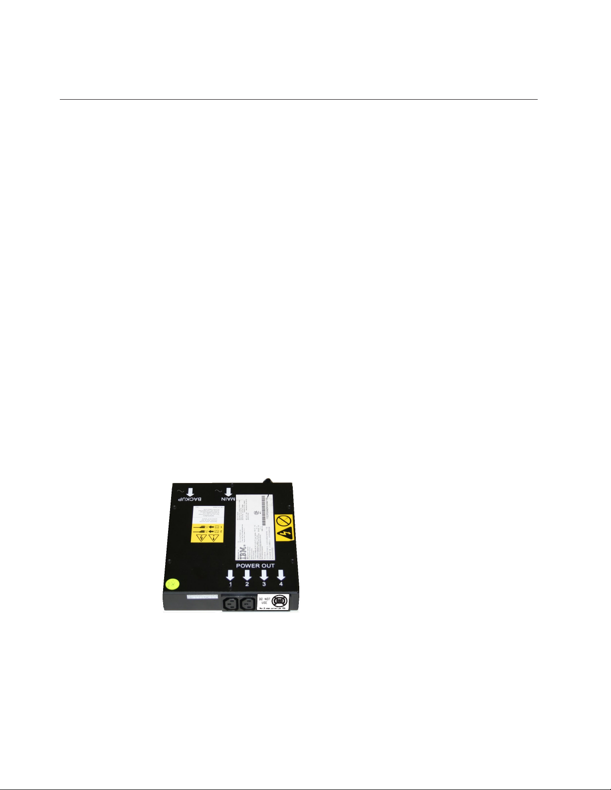
Figure 1 shows a redundant ac-power switch.
svc00297
Figure 1. Photo of the redundant ac-power switch
Cabling of redundant ac-power switch (example)
You must properly cable the redundant ac-power switch units in your
environment.
Note: While this topic provides an example of the cable connections, it does not
indicate a preferred physical location for the components.
2 SAN Volume Controller: Model 2145-CG8 Hardware Installation Guide
Page 31

Figure 2 shows an example of the main wiring for a SAN Volume Controller
clustered system with the redundant ac-power switch feature. The four-node
clustered system consists of two I/O groups:
v I/O group 0 contains nodes A and B
v I/O group 1 contains nodes C and D
2
1
6
3
4
5
7
8
9
10
11
12
14
Figure 2. A four-node SAN Volume Controller system with the redundant ac-power switch
feature
13
svc00358_cf8
1 I/O group 0
2 SAN Volume Controller node A
3 2145 UPS-1U A
4 SAN Volume Controller node B
5 2145 UPS-1U B
6 I/O group 1
7 SAN Volume Controller node C
8 2145 UPS-1U C
9 SAN Volume Controller node D
Chapter 1. SAN Volume Controller overview 3
Page 32

10 2145 UPS-1U D
11 Redundant ac-power switch 1
12 Redundant ac-power switch 2
13 Site PDU X (C13 outlets)
14 Site PDU Y (C13 outlets)
The site PDUs X and Y (13 and 14) are powered from two independent power
sources.
In this example, only two redundant ac-power switch units are used, and each
power switch powers one node in each I/O group. However, for maximum
redundancy, use one redundant ac-power switch to power each node in the
system.
Some SAN Volume Controller node types have two power supply units. Both
power supplies must be connected to the same 2145 UPS-1U, as shown by node A
and node B. The SAN Volume Controller 2145-CG8 is an example of a node that
has two power supplies. The SAN Volume Controller 2145-8A4 is an example of a
node that has a single power supply.
Uninterruptible power supply
The uninterruptible power supply protects a SAN Volume Controller node against
blackouts, brownouts, and power surges. The uninterruptible power supply
contains a power sensor to monitor the supply and a battery to provide power
until an orderly shutdown of the system can be performed.
SAN Volume Controller 2145-CG8 uses the 2145 UPS-1U.
2145 UPS-1U
A 2145 UPS-1U is used exclusively to maintain data that is held in the SAN
Volume Controller dynamic random access memory (DRAM) in the event of an
unexpected loss of external power. This use differs from the traditional
uninterruptible power supply that enables continued operation of the device that it
supplies when power is lost.
With a 2145 UPS-1U, data is saved to the internal disk of the SAN Volume
Controller node. The uninterruptible power supply units are required to power the
SAN Volume Controller nodes even when the input power source is considered
uninterruptible.
Note: The uninterruptible power supply maintains continuous SAN Volume
Controller-specific communications with its attached SAN Volume Controller
nodes. A SAN Volume Controller node cannot operate without the uninterruptible
power supply. The uninterruptible power supply must be used in accordance with
documented guidelines and procedures and must not power any equipment other
than a SAN Volume Controller node.
2145 UPS-1U configuration
A 2145 UPS-1U powers one SAN Volume Controller node.
To make the SAN Volume Controller clustered system more resilient against power
failure, the 2145 UPS-1U units can be connected to the redundant ac-power switch.
4 SAN Volume Controller: Model 2145-CG8 Hardware Installation Guide
Page 33

If a redundant ac-power switch is not used, the two uninterruptible power
supplies that power an I/O group can be connected to different, independent
electrical power sources. In this case, if a single power source fails, only one node
in the I/O group stops and the SAN Volume Controller system can continue to
operate, although with reduced performance.
Each uninterruptible power supply must be in the same rack as the node that it
powers.
Each 2145 UPS-1U includes one power cord that connects the uninterruptible
power supply to a redundant ac-power switch, if one exists, or to a rack power
distribution unit (PDU), if one exists. The 2145 UPS-1U also includes an alternative
power cable to connect to an external power source that is specific to your
geography.
Each 2145 UPS-1U is connected to a SAN Volume Controller node with a power
cable and a signal cable. To avoid the possibility of power and signal cables being
connected to different uninterruptible power supplies, these cables are wrapped
together and supplied as a single field-replaceable unit (FRU). The SAN Volume
Controller node reads status and identification information from the
uninterruptible power supply using the signal cable.
Chapter 1. SAN Volume Controller overview 5
Page 34

6 SAN Volume Controller: Model 2145-CG8 Hardware Installation Guide
Page 35

Chapter 2. Installing the SAN Volume Controller 2145-CG8 hardware
There are several steps that you must perform to prepare, and then install the SAN
Volume Controller hardware.
Before you begin
To install the SAN Volume Controller hardware, perform the following tasks in
order.
Note: If you are adding a new I/O group to an existing SAN Volume Controller
clustered system, there is no need to turn off the existing, operating system nodes.
Procedure
1. Prepare for the SAN Volume Controller hardware installation by confirming
that you have all the planning information and parts that you require.
2. Optionally, install and verify the operation of the redundant ac-power switch, if
the redundant ac-power switch is not already in use for a node.
3. Install the uninterruptible power supply.
4. Install the node.
5. Connect the Fibre Channel and Ethernet cables to the node.
6. Connect the node to the uninterruptible power supply.
7. Verify that the node is operational.
Results
After you finish these steps, the hardware installation is complete. The customer is
responsible for all configuration tasks.
Preparing for the hardware installation
You must prepare for the installation of the optional redundant ac-power switch,
the uninterruptible power supply, and the SAN Volume Controller.
Before you begin
Figure 3 on page 8 shows the major hardware components that you need.
© Copyright IBM Corp. 2012 7
Page 36

1
1
2
8
3
4
6
6
7
10
11
Figure 3. Parts provided for SAN Volume Controller 2145-CG8 hardware installation in a rack
9
5
svc00741
1 SAN Volume Controller node
2 SAN Volume Controller support rails (2)
3 2145 UPS-1U
4 2145 UPS-1U support rails (2)
5 Power cable assembly
6 SAN Volume Controller cable-management support arm
7 SAN Volume Controller cable-management arm assembly
8 Optionally, one or more redundant ac-power switches, two mounting
brackets per switch, and power cables
8 SAN Volume Controller: Model 2145-CG8 Hardware Installation Guide
Page 37

9 2145 UPS-1U cable-retention bracket
10 SAN Volume Controller cable-retention brackets
11 2145 UPS-1U mounting brackets
Not shown in Figure 3 on page 8 are two 2145 UPS-1U input-power cables that are
provided. One cable comes with the 2145 UPS-1U; it has an IEC 320-C14 plug,
which is suitable for most rack-mounted power distribution units. The other
country-specific cable comes with the SAN Volume Controller node; this cable is
intended for your country-specific power sockets. Use only one of these cables.
Before you start the installation, verify that all the parts that were ordered have
been received and that all the component assemblies are complete. Verify that you
know the quantity of nodes and optional features that were ordered.
Three boxes are shipped for each node: one box contains the uninterruptible power
supply, one box contains the publications, and the third box contains all the other
parts. A label on the third, or main, box indicates the features that were shipped.
Note:
1. You must install at least two SAN Volume Controller nodes. Each node requires
an uninterruptible power supply.
2. Optionally, install two redundant ac-power switches to power the nodes in an
I/O group through two 2145 UPS-1U units.
3. You must ensure that you have the appropriate cables to connect the redundant
ac-power switch or uninterruptible power supply to the power distribution
unit. See Appendix B, “SAN Volume Controller physical installation planning,”
on page 47 for more details.
About this task
Perform the following steps to prepare for installation:
Procedure
1. Ensure that you have everything you need for installation, including the
customer-completed planning tables and charts. The customer can obtain the
planning tables and charts from www.ibm.com/storage/support/2145.
The SAN Volume Controller planning information provides guidelines for
completing the planning tables and charts. These tables include the location of
hardware, cable connection, and configuration data information that you need
to complete the installation procedures. If you are connecting cables to switches
that are currently in use, confirm with the customer that it is safe for you to
proceed. Go no further with these instructions until you are satisfied that all
the information is correct and valid.
2. The label on the main box indicates features that were shipped. Make sure that
the contents and quantity match the order.
The following feature codes are included:
v Feature code 0010: initial SAN Volume Controller 2145-CG8 software
preinstalled on feature code 3001 and 3002
v One of the following:
– Feature code 3001: initial SAN Volume Controller 2145-CG8 node, quantity
1
– Feature code 3002: additional SAN Volume Controller 2145-CG8 node,
quantity 1
Chapter 2. Installing the SAN Volume Controller 2145-CG8 hardware 9
Page 38

v Feature code 5608: Fibre Channel longwave small form-factor pluggable
(SFP) transceiver, quantity1-4
v Optionally, feature code 4500: Solid-state drive (SSD) attachment, quantity 1
v Optionally, feature code 4601: 146 GB Solid-state drive (SSD), quantity1-4
v Optionally, feature codes 5700 and 5711: 10 Gbps Ethernet adapter, quantity 1
and SFP transceivers, quantity 2; the single feature code contains both SFPs.
Both feature codes preinstalled on feature code 3001 and 3002
v One of the following country-specific SAN Volume Controller 2145-CG8
power cable feature codes: 9714, 9715, 9716, 9717, 9718, 9719, 9720, 9721,
9722, 9723, 9724, 9725, 9726, or 9727.
v Feature code 8115: 2145 UPS-1U kit, quantity 1
v Optionally, feature codes 5305 and 5325 for SAN Volume Controller
fiber-optic, Fibre Channel, or 10 Gbps Ethernet cables, quantity1-6
v Optionally, feature code 8300: redundant ac-power switch, quantity 1
3. Check that the correct part set has been shipped for the feature codes. Unless
otherwise stated, the feature code contents are in the main box.
v Feature code 0010 is preinstalled software. There is no shipped part for this
software.
v Feature codes 3001 and 3002 ship the same parts. Verify that you have the
listed parts:
– SAN Volume Controller 2145-CG8 node
– Part number 69Y1365: SAN Volume Controller 2145-CG8 Support rail kit,
quantity 1
– Part number 69Y1366: SAN Volume Controller 2145-CG8
Cable-management arm assembly, quantity 1
– Part number 31P1105: SAN Volume Controller publications and 31P1242:
ship group in a separate box
31P1105 contains:
- SAN Volume Controller Publications CD
- SAN Volume Controller Read first
- IBM Systems Safety Notices
- IBM System Storage SAN Volume Controller Model 2145-CG8 Hardware
Installation Guide
- IBM System Storage SAN Volume Controller Troubleshooting Guide
- IBM System Storage SAN Volume Controller Hardware Maintenance Guide
- SAN Volume Controller License information for IBM CIM agent and
console for management GUI
- SAN Volume Controller License information for SAN Volume Controller
- SAN Volume Controller Statement of Limited Warranty
- IPLA booklet for warranted products
- ILA booklet with pointer sheet
- IBM agreement for acquisition of support
- IBM license information for machine code
- Other miscellaneous flyers
– 31P1242 contains:
- Part number 31P1243: SAN Volume Controller power cable-retention
brackets, quantity 2
10 SAN Volume Controller: Model 2145-CG8 Hardware Installation Guide
Page 39

- Part number 31P1294: Kit containing the power and signal cable bundle,
quantity 1
– The support rail kit contains a number of components within its box.
Verify that you have the following items:
- One left side rail
- One right side rail
- Four M6 screws in a plastic ziplock bag
v Feature codes 9714, 9715, 9716, 9717, 9718, 9719, 9720, 9721, 9722, 9723, 9724,
9725, 9726, and 9727 each ship a single power cable. Use the power plug that
is appropriate to your location unless you are connecting to a rack-mounted
power distribution unit.
v Optional feature code 5608 ships uninstalled, quantity1-4
v Optional feature code 4500 ships installed in the SAN Volume Controller
2145-CG8 node, quantity 1
v Optional feature code 4601 ships installed in the SAN Volume Controller
2145-CG8 node, quantity1-4
v Optional feature codes 5700 and 5711 ship installed in the SAN Volume
Controller 2145-CG8 node, quantity 1 each
v Feature code 8115 ships in a separate box that is labeled part number
31P1391. Verify that the box contains these items:
– 2145 UPS-1U, quantity 1
– 2145 UPS-1U output power-cable retention-bracket kit, quantity 1
– Cable clip and two screws in plastic ziplock bag
– Uninterruptible power-supply rail kit, quantity 1
– Power cable for connecting the uninterruptible power supply to a rack;
PDU, quantity 1
– Multilingual battery-reconnection flyer and other miscellaneous flyers
– Environmental Notices and User's Guide CD
v Optional feature code 8300 ships in a box within the main box. Verify that
the box contains the following items:
– Part number 95P5083: redundant ac-power switch, quantity 1
– Part number 31P0966: power cables, quantity 2
– Part number 96P1728: mounting plates, quantity 2
– Part number 12J5289: hex head screws, quantity 4
– Part number 00N8709: “c” clips, quantity 4
– Part number 24R0207: other screws, quantity 6
– Part number 31P0876: label set, quantity 1
If feature codes 5305 or 5325 are not ordered for Fibre Channel connection, the
customer must supply their own fiber-optic Fibre Channel cables. Make sure
that four cables per node are available.
If feature codes 5700 and 5711 are ordered, and feature codes 5305 and 5325 are
not ordered for Ethernet connection, the customer must supply their own OM2
or OM3 fiber-optic cables. Make sure that two cables per node are available.
Note: Part numbers are subject to change between SAN Volume Controller
releases. The part numbers listed here might not always reflect what the
customer has received.
4. Read “Safety and environmental notices” on page ix to ensure that you are
correctly installing the 2145 UPS-1U units.
Chapter 2. Installing the SAN Volume Controller 2145-CG8 hardware 11
Page 40

Optionally installing the redundant ac-power switch
Use the redundant ac-power switch to make the SAN Volume Controller clustered
system more resilient to power failure.
Before you begin
DANGER
Multiple power cords: The product is equipped with multiple power cords.
To remove all hazardous voltages, disconnect all power cords. (L003)
1
or
2
svc00322
1
2
svc00323
The following topics describe the redundant ac-power switch installation tasks in
the order that they must be performed:
Procedure
1. Attach the mounting plates to the redundant ac-power switch.
2. Label the cables.
3. Connect the power input cables to the redundant ac-power switch.
4. Install the redundant ac-power switch in the rack.
5. Connect the redundant ac-power switch to the site power.
6. Test the redundant ac-power switch to ensure that it automatically switches
power supplies when the main power source fails or is restored.
Attaching the mounting plates to the redundant ac-power switch
Attach the mounting plates to the redundant ac-power switch before you label the
cables.
12 SAN Volume Controller: Model 2145-CG8 Hardware Installation Guide
Page 41

About this task
Perform the following steps to attach the mounting plates to the redundant
ac-power switch.
Procedure
1. Attach each of the two mounting plates to the redundant ac-power switch
using three M3 Torx T8 head screws.
2. Position the mounting face on the side of the redundant ac-power switch
containing the output power sockets. See Figure 4.
svc00294
Figure 4. Attaching the mounting plates
Labeling the cables
You must label each end of the two redundant ac-power switch input-power cables
before you connect the input-power cables to the redundant ac-power switch.
About this task
Perform the following steps to label each end of the two redundant ac-power
switch input-power cables:
Procedure
1. Label the rack power-distribution end “Power source <name>, outlet <id> to
redundant ac-power switch <location> <MAIN | BACKUP> input.” For
example, “Power source D2, outlet 4 to redundant ac-power switch pos 7
MAIN input.” One cable is labeled “MAIN;” the other is labeled “BACKUP.”
2. Label the redundant ac-power switch end “redundant ac-power switch
<location> <MAIN | BACKUP> input from Power source <name>, outlet
<id>.” One cable is labeled “MAIN;” the other is labeled “BACKUP.”
Connecting the input-power cables to the redundant ac-power switch
You will find it easier to connect the input-power cables to the redundant ac-power
switch before you install the redundant ac-power switch in the rack.
About this task
Perform the following steps to connect the input-power cables to the redundant
ac-power switch:
Chapter 2. Installing the SAN Volume Controller 2145-CG8 hardware 13
Page 42

Procedure
1. Connect the main input-power cable to the redundant ac-power switch.
2. Connect the backup input-power cable to the redundant ac-power switch.
3. Secure both the redundant ac-power switch input-power cables using the clips
of the redundant ac-power switch. See Figure 5.
Figure 5. Power cable clips
svc00291
Installing the redundant ac-power switch in the rack
You must install the redundant ac-power switch in the rear of the rack before you
connect the redundant ac-power switch to the site power.
Before you begin
Perform the following steps to install the redundant ac-power switch in the rack:
Procedure
1. Use the hardware location chart to determine where to install the redundant
ac-power switch in the rack. The redundant ac-power switch can be installed
horizontally in a rack slot or vertically in one of the side slots of the rack.
2. Position the four “C” clips in the rack's mounting bar, as shown in Figure 6 on
page 15.
14 SAN Volume Controller: Model 2145-CG8 Hardware Installation Guide
Page 43

svc00292
Figure 6. Positioning the clips
3. Position the redundant ac-power switch in the rack first, pushing the cables
through to the front of the rack. Mount in place, as shown in Figure 7, using
the four M6 screws.
Figure 7. Positioned in rack
Connecting the redundant ac-power switch to the site power
You must connect the redundant ac-power switch to the site power before you test
the redundant ac-power switch.
About this task
Perform the following steps to connect the redundant ac-power switch to the site
power:
Procedure
1. Determine a suitable cable route from the redundant ac-power switch to the
power distribution units.
2. Route the main input-power cable of the redundant ac-power switch to the
specified power distribution unit, and connect it.
3. Route the backup input-power cable of the redundant ac-power switch to the
specified power distribution unit, and connect it.
Chapter 2. Installing the SAN Volume Controller 2145-CG8 hardware 15
Page 44

4. Verify that the redundant ac-power switch power cables are tidy. Ensure that
they do not obstruct other equipment and that they are tied in place where
necessary.
Testing the redundant ac-power switch
You can test the redundant ac-power switch before you continue installing other
SAN Volume Controller components. You can test the redundant ac-power switch
later if a suitable test device is not available.
About this task
You can test whether the redundant ac-power switch correctly switches between
power inputs when the main input power fails or is restored. You can either use a
volt meter to measure for voltage at the output or attach a work light, or similar
device with a C14 plug, to the redundant ac-power switch output and verify that it
remains powered when a failure is simulated on either of the inputs.
Notes:
v If you do not have a separate device to verify that there is power on the output
port of the redundant ac-power switch, you can delay this test until you connect
the redundant ac-power switch to the uninterruptible power supply. In that case,
turn on the uninterruptible power supply (not the SAN Volume Controller node)
and see if it changes to battery power. The test fails if the uninterruptible power
supply switches to battery power for more than five seconds.
v Any transient indications of battery power can be ignored.
When the instructions say to “remove power,” you can either turn the power off if
the site power-distribution unit (PDU) has outputs that are individually switched
or remove the specified redundant ac-power switch power cable from the outlet of
the site PDU.
Note: If at any time there is no power on the output socket, ensure that the power
distribution sockets of the power source are turned on. If they are, recheck all of
the connections and decide if the redundant ac-power switch assembly, which
includes the input-power cables, is defective.
Perform the following steps to test the redundant ac-power switch:
Procedure
1. Confirm that there is power at redundant ac-power switch output socket 2.
2. Confirm that there is power at redundant ac-power switch output socket 1.
3. Remove power from the main power cable to the redundant ac-power switch
and confirm that there is power at the redundant ac-power switch output 1.
4. Reconnect the main power cable.
5. Remove power from the backup power cable to the redundant ac-power switch
and confirm that there is power at the redundant ac-power switch output 1.
6. Reconnect the backup power cable and remove the monitoring device.
Note: After any failure, repeat the test phase from the start until all the tests
succeed.
16 SAN Volume Controller: Model 2145-CG8 Hardware Installation Guide
Page 45

Installing the 2145 UPS-1U
Before you can use the SAN Volume Controller, you need to install the
uninterruptible power supply.
About this task
Complete the following steps to install the 2145 UPS-1U:
Procedure
1. Install the support rails for the 2145 UPS-1U.
2. Install the 2145 UPS-1U in the rack.
3. Install the 2145 UPS-1U cable-retention bracket.
Installing the support rails for the 2145 UPS-1U
You must install the support rails in the rack before installing the 2145 UPS-1U.
Before you begin
Complete these prerequisites before installing the support rails:
1. Use the customer's hardware-location chart to determine where in the rack to
install the 2145 UPS-1U.
2. At the back of the rack, observe the Electronic Industries Alliance (EIA)
positions and determine where you are going to install the 2145 UPS-1U.
Because of its weight, position the 2145 UPS-1U where it is easy to handle in
one of the lower positions in the rack.
About this task
Perform the following steps to install the support rails for the 2145 UPS-1U:
Procedure
1. Open the top of the 2145 UPS-1U shipping carton. Grip the flaps on either side
of the 2145 UPS-1U.
2. Lift the 2145 UPS-1U clear of the shipping carton and place it on a flat, stable
surface with the front facing you.
3. Attach the long side of a mounting bracket 1 to each side of the 2145 UPS-1U
using four M3 × 6 screws 2 for each bracket, as shown in Figure 8 on page
18.
Chapter 2. Installing the SAN Volume Controller 2145-CG8 hardware 17
Page 46

1
LD2LD2
LD1
Figure 8. Installing the 2145 UPS-1U mounting brackets for the 2145 UPS-1U
4. Loosen the wing nuts (1 and 2) on both rail assemblies and adjust the rail
size to the depth of your rack. After you adjust the depth, tighten the wing
nuts as much as possible while still allowing some movement.
Refer to Figure 9 for information about how to tighten or loosen wing nuts and
achieve a desired rail depth.
2
svc00742
Rear
2
1
Figure 9. Adjusting the rail depth on the 2145 UPS-1U
Wing nut 1
Wing nut 2
5. Select the holes in the rail where you want to position the uninterruptible
power supply.
The figure shows the rear rail where the 2145 UPS-1U attaches to the rack. See
Figure 10 on page 19.
Note: The bottom flange of the support rail must align with the EIA mark on
the rack.
Front
svc00737
18 SAN Volume Controller: Model 2145-CG8 Hardware Installation Guide
Page 47

2
1
Figure 10. Attaching the rear of the 2145 UPS-1U rail to the rack
6. Install 2 clip nuts 2 and 2 M6 x 10 screws 1, to attach the rail to the rear of
the rack.
7. Install 2 clip nuts 2 and 3 to the front of the rack. Then attach the rail
using just 1 M6 x 10 screw 1 in the bottom mounting hole as shown in
Figure 11 on page 20.
svc00738
Note:
a. The extra clip nut 3 is reserved for later installation of the 2145 UPS-1U
when the mounting brackets must be attached to the vertical rail on the
rack.
b. The rack might be different from the one shown here, and if so, might
require different clip nuts or fasteners.
Chapter 2. Installing the SAN Volume Controller 2145-CG8 hardware 19
Page 48

3
2
Figure 11. Attaching the front of the 2145 UPS-1U rail to the rack.
8. Repeat steps 6 on page 19 and 7 on page 19 for the other rail.
9. Tighten the wing nuts on both rail assemblies.
1
svc00739
Installing the 2145 UPS-1U in the rack
After you have completed the preparation procedures, you are ready to install the
2145 UPS-1U in the rack.
Before you begin
Attention: See “Safety and environmental notices” on page ix before you start
the installation process. Use the reference numbers in parentheses at the end of
each safety notice to find the matching translated notice. For the translation of the
danger, caution, and attention notices, see the IBM Systems Safety Notices.
CAUTION:
The uninterruptible power supply contains its own energy source (sealed,
lead-acid batteries). The output receptacles might carry live voltage, even when
the uninterruptible power supply is not connected to an ac supply. (11)
CAUTION:
Do not remove or unplug the input cord when the uninterruptible power supply
is turned on. Unplugging the input cord removes the safety ground from the
uninterruptible power supply and the equipment connected to the
uninterruptible power supply. (12)
CAUTION:
To reduce the risk of fire or electric shock, install the uninterruptible power
supply in a temperature- and humidity-controlled indoor environment, free of
conductive contaminants. Ambient temperature must not exceed 40°C (104°F). Do
not operate near water or excessive humidity (95% maximum). (13)
20 SAN Volume Controller: Model 2145-CG8 Hardware Installation Guide
Page 49

CAUTION:
To avoid any hazard from the rack tipping forward when devices are installed,
observe all safety precautions for the rack into which you are installing the
device.
About this task
Perform the following steps to install the 2145 UPS-1U in the rack.
Note: You might have already completed steps 3 through 6 on page 23 if you used
the Read Me First pamphlet, which is included with the 2145 UPS-1U.
Procedure
1. Stand at the front of the rack and place the back of the 2145 UPS-1U onto the
support rails, and then slide the 2145 UPS-1U into the rack.
CAUTION:
The 2145 UPS-1U weighs 16 kg (35.3 lb). If you feel unsure about lifting the
uninterruptible power supply to its location in the rack, seek assistance or
remove the battery to reduce its weight.
2. At the front of the 2145 UPS-1U, install the two mounting screws (M6x10) 1
as shown in Figure 12.
1
Figure 12. Mounting screws for the 2145 UPS-1U
3. If you have not already connected the internal battery connector, remove the
2145 UPS-1U front panel, shown in “Installing the 2145 UPS-1U in the rack” on
page 20, by pulling the panel forward (1), then pushing to the left (2).
Chapter 2. Installing the SAN Volume Controller 2145-CG8 hardware 21
svc00008
Page 50

2
1
Figure 13. Removing the 2145 UPS-1U front panel
4. Remove the protective label from the internal battery connector (shown in
Figure 14).
svc00740
Figure 14. The 2145 UPS-1U internal battery connector with protective tape
5. Connect the internal battery connector (shown in Figure 15 on page 23). Each
end of the keyed connector has two wires: one red (+) and one black (−). Align
the connector so that the two red wires are joined together and the two black
wires are joined together.
Note: A small amount of arcing might occur when connecting the batteries.
This is normal and does not damage the unit or present any safety concerns.
22 SAN Volume Controller: Model 2145-CG8 Hardware Installation Guide
svc00062
Page 51

svc00061
Figure 15. The 2145 UPS-1U internal-battery connector
6. Reinstall the front panel. You might first need to move the sliding section on
the front of the 2145 UPS-1U to the closed position.
7. At the back of the 2145 UPS-1U, plug the 2145 UPS-1U main-power connector
into the power socket.
The power socket is shown by 1 in Figure 16.
The 2145 UPS-1U is in standby mode; so all indicators are off.
Connect each 2145 UPS-1U for an I/O group to a different power source.
1
Figure 16. 2145 UPS-1U (rear view)
2
3
1 Main power connector
2 Communication port
3 Load segment 2 receptacles
Attention: Ensure that you comply with the following requirements:
v The voltage supplied to the 2145 UPS-1U must be 200 - 240 V single phase.
v The frequency supplied must be 50 or 60 Hz.
Notes:
a. The 2145 UPS-1U has an integrated circuit breaker and does not require
external protection.
b. The 2145 UPS-1U is intended to maintain power on SAN Volume Controller
nodes until data can be saved to the local hard-disk drive. Only SAN
Volume Controller nodes can be plugged into the 2145 UPS-1U or the SAN
Volume Controller clustered system will malfunction.
8. Press and hold the on/off button (7 in Figure 17 on page 24) for
approximately five seconds. You might need a pointed device, such as a
Chapter 2. Installing the SAN Volume Controller 2145-CG8 hardware 23
svc_06031737
Page 52

screwdriver, to press the on/off button. The front panel indicators cycle
through a startup sequence while the 2145 UPS-1U conducts a self-test.
LOAD 1LOAD 2
1 2 3 4 5
Figure 17. 2145 UPS-1U front-panel assembly
+ -
6
When the self-test is complete, the power-on indicator 6 and the load
indicators (1 and 2) illuminate to indicate that power is being supplied by
the 2145 UPS-1U. The 2145 UPS-1U is now in normal mode, and is charging its
battery. If the battery indicator 4 is on and the alarm is sounding, the voltage
range setting might not be correct. When a SAN Volume Controller is
connected to the 2145 UPS-1U, the SAN Volume Controller automatically
adjusts the voltage range setting. Take no action for this alarm condition unless
it persists for more than five minutes after a SAN Volume Controller has been
connected to this 2145 UPS-1U and turned on.
9. Repeat all of these steps to install additional 2145 UPS-1U units.
Installing the 2145 UPS-1U cable-retention bracket
The 2145 UPS-1U cable-retention bracket ensures that the power cable connection
between the 2145 UPS-1U and the SAN Volume Controller node is stable.
7
8
1yyzvm
Before you begin
Install the bracket after you install the power and signal cable assembly that was
supplied with the node to connect the 2145 UPS-1U and the node.
About this task
You can attach the bracket by performing the following steps:
Procedure
1. Install the power cable into the rightmost power outlet on the rear of the 2145
UPS-1U.
2. Remove the bracket and the two screws (shown in Figure 18 on page 25) from
the packaging.
24 SAN Volume Controller: Model 2145-CG8 Hardware Installation Guide
Page 53

Figure 18. 2145 UPS-1U power cable-retention bracket hardware
3. Place the bracket over the power outlets on the right rear of the 2145 UPS-1U,
so that the two screw holes line up.
4. Position the bracket with the power cable protruding through the rightmost slot
in the bracket.
5. Secure the bracket in place with one screw on each side, as shown in Figure 19.
Figure 19. 2145 UPS-1U power cable-retention bracket
Installing the SAN Volume Controller 2145-CG8
There are several steps that you must perform to install the SAN Volume
Controller 2145-CG8 node.
svc00201
About this task
Installing the SAN Volume Controller 2145-CG8 consists of the following tasks:
1. Installing the support rails in the rack cabinet.
2. Installing the SAN Volume Controller 2145-CG8 node.
3. Installing the cable-management arm in the rack cabinet.
4. Connecting the SAN Volume Controller 2145-CG8 node to the uninterruptible
power supply.
Chapter 2. Installing the SAN Volume Controller 2145-CG8 hardware 25
Page 54

Installation guidelines
Before you install the support rails for the SAN Volume Controller 2145-CG8 node,
review the following guidelines:
Before you begin
v Do not install a unit in a rack where the internal-rack ambient temperature
exceeds the lowest manufacturer-recommended ambient temperature for all of
your rack-mounted devices.
v Do not install a unit in a rack where the air flow is compromised. Ensure that
air flow is not blocked or reduced on any side, front, or back of a unit used for
air flow through the unit.
v Ensure that the equipment is connected properly to the supply circuit so that the
circuits do not overload and compromise the supply wiring or overcurrrent
protection.
v Plan the device installation by starting at the bottom of the rack cabinet to
ensure that the rack is stable and cannot tip over.
v Install the heaviest device in the bottom of the rack cabinet.
v Do not install a SAN Volume Controller node directly above the pull-out
monitor and keyboard of the IBM System Storage Productivity Center (SSPC)
server. The front panel of the node protrudes beyond the front of the rack and
overlaps part of the monitor, which prevents you from opening it.
Installing the support rails for the SAN Volume Controller 2145-CG8
You must install the support rails that hold the SAN Volume Controller 2145-CG8
node.
Before you begin
Figure 20 shows the items that you need to install the SAN Volume Controller
2145-CG8 node in a rack.
Cable management arm kit
Friction rail kit
6
5
Figure 20. SAN Volume Controller 2145-CG8 cable-management arm, support rails, and associated parts
7
4
1
2
3
26 SAN Volume Controller: Model 2145-CG8 Hardware Installation Guide
Page 55

Table 4. Cable-management arm and associated parts descriptions and quantities
Reference Description Quantity
1 Slide rail (left) 1
2 Slide rail (right) 1
3 M6 screws 4
4 Large cable tie 1
5 Cable ties 5
6 Cable-management support arm 1
7 Cable-management arm assembly 1
Notes:
v With some types of racks, you might find it helpful to remove the rack doors
and side panels to provide easier access during installation.
v The slide rails are marked (RIGHT / FRONT and LEFT / FRONT) for proper
placement on the rack flanges.
v The front and back of each rail has a spring-loaded rail-locking carrier, which
can be locked in the open position and then released when the rail is in the rack.
When you are ready to install the support rails, use the customer's
hardware-location chart and the Electronic Industries Alliance (EIA) positions on
the rack to determine where in the rack that the SAN Volume Controller node is to
be installed.
About this task
Perform the following steps to install the support rails:
Procedure
1. Verify that you have all the items that you need for installing the support rails
and that you have identified the front of each rail, as shown in Figure 20 on
page 26.
1 Slide rail (left)
2 Slide rail (right)
3 M6 screws
Note: You might find it helpful, with some types of racks, to remove the rack
doors and side panels to provide easier access during installation.
2. Open the rear-slide-rail hooks, as shown in Figure 21 on page 28.
Chapter 2. Installing the SAN Volume Controller 2145-CG8 hardware 27
Page 56

Figure 21. Opening the rear slide-rail hooks
Note: The maximum distance between the front and the rear EIA rails of the
rack is 810 mm (31.9 in.).
Each slide rail is marked with either an R (right) or an L (left). Select one of the
slide rails and pull the rear bracket all the way back. If a thumbscrew is
installed in the slide rail, remove it.
3. Install the rear end of the slide rails, as shown in Figure 22.
Rear of rack
Figure 22. Installing the rear end of the slide rails
From the front of the rack, line up the two pins on the rear of the slide rail in
the selected U on the rear of the rack. Push the rails so that the pins go into the
holes and slide the rails into the rack to lock the rear of the slide rails into the
rack.
4. Prepare the front end of the slide rails, as shown in Figure 23 on page 29.
28 SAN Volume Controller: Model 2145-CG8 Hardware Installation Guide
Page 57

Figure 23. Preparing the front end of the slide rails
Push the blue button to allow the latch to slide forward. Then pull the slide rail
forward and pull the latch on the front of the rail in the U on the front of the
rack. Adjust the length of the rail.
5. Install the front end of the slide rails, as shown in Figure 24.
Figure 24. Installing the front end of the slide rails
Press the blue button to release the bracket. Push the front latch in all the way.
Make sure the latch is fully engaged.
6. Install the other rail in the same manner.
Installing the cable-management arm for the SAN Volume Controller 2145-CG8
The SAN Volume Controller 2145-CG8 uses a cable-management arm to route and
secure power and communication cables.
Chapter 2. Installing the SAN Volume Controller 2145-CG8 hardware 29
Page 58

About this task
The parts involved in installing the cable-management arm are shown in Figure 25.
Cable management arm kit
1
Friction rail kit
6
5
Figure 25. SAN Volume Controller 2145-CG8 cable-management arm, support rails, and associated parts
Table 5. Cable-management arm and associated parts descriptions and quantities
7
4
Reference Description Quantity
1 Slide rail (left) 1
2 Slide rail (right) 1
3 M6 screws 4
4 Large cable tie 1
5 Cable ties 5
6 Cable-management support arm 1
7 Cable-management arm assembly 1
2
3
To attach the arm, perform the following steps:
Procedure
1. At the rear of the rack, install the cable-management-support arm.
Insert both ends of the cable management support arm into the slide rail, as
shown by Figure 26 on page 31.
30 SAN Volume Controller: Model 2145-CG8 Hardware Installation Guide
Page 59

Figure 26. Installing the cable-management-support arm
2. Install the cable management arm, as shown in Figure 27 on page 32.
Chapter 2. Installing the SAN Volume Controller 2145-CG8 hardware 31
Page 60

1
Figure 27. Installing the cable-management arm
Note: Make sure that the junctions on the arm, as shown by 1 in Figure 27,
are facing the SAN Volume Controller 2145-CG8.
Place the cable management arm on the support arm. Pull out both
cable-management-arm pins and then slide the cable-management-arm tabs into
the slots on both the inside and the outside of the slide rail. Push the tabs until
they snap into place.
3. Adjust the location of the cable management arm, as shown in Figure 28 on
page 33.
32 SAN Volume Controller: Model 2145-CG8 Hardware Installation Guide
Page 61

Figure 28. Adjusting the location of the cable-management arm
Make sure that the support rail is located between the 2 nailhead features.
4. You may wish to return to this section once these actions have been performed.
After you have installed the node and have attached the cables the rear of the
node:
a. Route the data cables and power cords along the cable-management arm, as
shown 1 in Figure 29 on page 34.
If you attach the arm properly and route the cables properly, the arm
swings into the rack as you pull the node forward in the rack, opening to
allow the cables to follow the node toward the front of the rack. You can
perform some service procedures without disconnecting the Fibre Channel
cables and the Ethernet cables. You can also perform some service
procedures without turning off the node or disconnecting the power cables.
b. Secure the cables with cable ties or hook-and-loop fasteners.
Note: Leave some slack in all of the cables to avoid tension in the cables as the
cable-management arm moves.
Chapter 2. Installing the SAN Volume Controller 2145-CG8 hardware 33
Page 62

Figure 29. Connecting and routing the cables
Installing the SAN Volume Controller 2145-CG8 in a rack
After installing the support rails, you can install the SAN Volume Controller
2145-CG8 node in the rack.
Before you begin
CAUTION:
To avoid any hazard from the rack tipping forward when devices are installed,
observe all safety precautions for the rack into which you are installing the
device.
About this task
To install the SAN Volume Controller 2145-CG8 node in the rack, perform the
following steps:
Procedure
1. Place the SAN Volume Controller 2145-CG8 in the rails on the rack.
a. Pull the slide rails forward until they click twice into place.
See 1 in Figure 30 on page 35.
b. Lift the node and carefully tilt it into position over the slide rails. Line up
the rear nail heads 2 on the node line up with the rear slots 3 on the
slide rails.
c. Slide the node down until the rear nail heads slip into the two rear slots.
34 SAN Volume Controller: Model 2145-CG8 Hardware Installation Guide
Page 63

d. Lower the front of the node 4 until the other nail heads slip into the other
slots on the slide rails.
e. Verify that the front latch 5 slides over the nail heads.
svc_bb1ka020
Figure 30. Installing the SAN Volume Controller 2145-CG8 node in the slide rails of the rack
2. Lift the locking levers on the slide rails and push the node 2 all the way into
the rack until it clicks into place.
See 1 in Figure 31.
svc_bb1ka055
Figure 31. Raising the SAN Volume Controller 2145-CG8 locking levers of the slide rails of
the rack
Connecting the SAN Volume Controller 2145-CG8 to the 2145 UPS-1U
Connect the SAN Volume Controller to the 2145 UPS-1U to protect your data in
the event of an unexpected loss of external power.
Before you begin
Notes:
v To make the SAN Volume Controller clustered system more resilient to power
failure, the 2145 UPS-1U units can be connected to the redundant ac-power
switch. If a redundant ac-power switch is not used, you can connect the two
Chapter 2. Installing the SAN Volume Controller 2145-CG8 hardware 35
Page 64

uninterruptible power-supply units that are powering an I/O group to different,
independent electrical power sources. If a single power source fails, the SAN
Volume Controller system can then continue to operate with reduced
performance.
v When connecting to the 2145 UPS-1U, use only the power cable assembly, part
number 31P1294, that was supplied with the node. Power cable assemblies that
were supplied with previous SAN Volume Controller models do not work with
the 2145-CG8 model because there are two power cables in the bundle for the
2145-CG8 model. The correct part is differentiated by the blue tape that binds
the cables together.
Before you begin this task, see the completed customer's cable-connection table,
which is described in the IBM System Storage SAN Volume Controller Planning Guide
and can be downloaded from the www.ibm.com/storage/support/2145.
Use the information in this table to identify the 2145 UPS-1U unit to which this
node is to be connected.
Perform the following steps to connect the SAN Volume Controller to the 2145
UPS-1U:
Procedure
1. At the back of the SAN Volume Controller 2145-CG8 node, plug the power
cables of the combined power and serial cable assembly into the power
connector 2, as shown in Figure 32.
1
4
5
Figure 32. Connecting the SAN Volume Controller power cable to the 2145 UPS-1U
3
6
2
7
1 Fibre Channel ports
2 Power connector
3 Serial connector
4 Ethernet ports
5 Main-power connector
svc00540
36 SAN Volume Controller: Model 2145-CG8 Hardware Installation Guide
Page 65

6 Communication port
7 Load-segment 2 receptacle
2. Place the other end of the power cables into the load-segment 2 receptacles 7
on the 2145 UPS-1U.
DANGER
You have already switched on the 2145 UPS-1U. The output sockets of the
2145 UPS-1U are live.
3. Plug the signal cable into the serial connector 3 located on the SAN Volume
Controller 2145-CG8 node.
4. Place the other end of the signal cable into the communication port 6 on the
2145 UPS-1U.
Results
The SAN Volume Controller 2145-CG8 power is now connected to the 2145
UPS-1U.
Installing the SAN Volume Controller 2145-CG8 cable-retention brackets
Two power cords run from the uninterruptible power-supply to each of the two
SAN Volume Controller 2145-CG8 power supplies. To anchor the power cords,
install the two cable-retention brackets on the back of the SAN Volume Controller
2145-CG8.
About this task
The cable-retention brackets install without tools, as shown in Figure 33.
2
1
Figure 33. SAN Volume Controller 2145-CG8 cable-retention brackets
To attach the brackets, perform the following steps:
Procedure
1. Loosely install the cable-retention bracket on a power cord by slipping the
power cord into the notch on the rear of the bracket.
Chapter 2. Installing the SAN Volume Controller 2145-CG8 hardware 37
Page 66

2. Align the cable-retention bracket on the power cord so that the bracket is to the
left side of the cord, as shown by 2 in Figure 33 on page 37.
3. Push both the bracket and the cable toward the SAN Volume Controller
2145-CG8 power supply (2), carefully aligning the power cord with the
power connector on the power supply and the bracket with the power-supply
handle.
4. Carefully push the bracket against the power-supply handle to force the spring
clip (1) over the leading edge of the handle.
5. Push the cable and the bracket into place, as shown in Figure 33 on page 37.
Connecting the SAN Volume Controller 2145-CG8 to the SAN and to the Ethernet network
Before you connect the SAN Volume Controller 2145-CG8 to the SAN, you must
connect the Ethernet and Fibre Channel cables.
Before you begin
Before you begin this task, see the customer's cable-connection table to find out
where to connect the Ethernet and Fibre Channel cables.
One or two 1 Gbps Ethernet cables can be connected to the SAN Volume
Controller 2145-CG8. The customer's cable connection table indicates the number of
cables to connect. If only one cable is connected, the cable must be connected to
Ethernet port 1.
About this task
To connect the SAN Volume Controller 2145-CG8 to the SAN and to the Ethernet
network, perform the following steps:
Procedure
1. Connect the Ethernet cables to Ethernet port 1, as shown by 9, and Ethernet
port 2 (8), in Figure 34.
2. Optional: If the 10 Gbps Ethernet feature is installed, you can connect Ethernet
optical cables to Ethernet port 3, as shown by 1, and Ethernet port 4 (2), in
Figure 35 on page 39.
3. Connect the other end of the Ethernet cable to the proper connector on the
Ethernet hub or switch.
1
Figure 34. Connectors on the rear of the SAN Volume Controller 2145-CG8
3
2
4
9
8
7
5
6
svc00732
1 Fibre Channel port 1
2 Fibre Channel port 2
3 Fibre Channel port 3
38 SAN Volume Controller: Model 2145-CG8 Hardware Installation Guide
Page 67

4 Fibre Channel port 4
5 Power-cord connector for power supply 1
6 Power-cord connector for power supply 2
7 Serial connection for UPS communication cable
8 Ethernet port 2
9 Ethernet port 1
2
1
Figure 35. 10 Gbps Ethernet ports on the rear of the SAN Volume Controller 2145-CG8
1 10 Gbps Ethernet port 3
2 10 Gbps Ethernet port 4
Attention: When routing the Fibre Channel cables, do not tighten the cable
straps or bend the cables to a radius smaller than 76 mm (3 in.).
4. Connect the Fibre Channel cables to the Fibre Channel ports as required by the
user's configuration.
5. Connect the other ends of the Fibre Channel cables to the proper connectors of
the Fibre Channel switches.
svc00731
Verifying the SAN Volume Controller 2145-CG8 installation
You must verify the SAN Volume Controller installation after the installation has
completed.
Before you begin
This task shows you how to verify the installation after you install the SAN
Volume Controller in the rack and connect it to the uninterruptible power supply,
the storage area network (SAN), and the Ethernet.
Note: If at any point the SAN Volume Controller does not operate as described,
see MAP 5000 in the IBM System Storage SAN Volume Controller Troubleshooting
Guide, unless a different maintenance analysis procedure (MAP) is specified.
About this task
Perform the following steps to verify installation:
Procedure
1. Press the SAN Volume Controller power-control button. Because the button is
recessed, you might need a pointed device, such as a screwdriver, to press the
power-control button. Verify that the green power LED is lit. If the LED is not
illuminated, see MAP 5000: Start in the IBM System Storage SAN Volume
Controller Troubleshooting Guide to repair the problem.
Note: You do not need to install any software. The node boots automatically.
Chapter 2. Installing the SAN Volume Controller 2145-CG8 hardware 39
Page 68

The SAN Volume Controller 2145-CG8 runs an extended series of power-on
self tests. The node might appear to be idle for up to five minutes after
powering on.
Figure 36 illustrates the controls and indicators on the front panel that verify
the installation.
1
6
Figure 36. SAN Volume Controller 2145-CG8 front panel
2
3
5
4
21
43
1 Node-status LED
2 Front-panel display
3 Navigation buttons
4Operator-information panel
5 Select button
6 Error LED
Verify that the node is booting without error. If it boots without error, either
the Charging, Recovering,ortheCluster: message is displayed in the first
line of the front-panel display.
2. Press and hold the select button for five seconds. The check light comes on
and a display test is performed. Check that all display cells light and that a
bar scrolls horizontally and vertically across the display. When the display test
is complete, the check light goes off and a button test is started.
3. Press the up, down, left, and right buttons to verify that they are working.
Figure 37 shows four examples of what the front panel might display when
you press the buttons. After you finish testing the buttons, press and hold the
select button for five seconds to exit the test.
svc00717
Figure 37. Front-panel display when push buttons are pressed
4. If the Charging or Recovering message is displayed on the front-panel display,
press the select button to switch to the menu. The menu continues to be
40 SAN Volume Controller: Model 2145-CG8 Hardware Installation Guide
Page 69

displayed while you press the buttons on the front panel. If you do not press
any buttons within 60 seconds, the menu changes to display the charging
progress. You can switch the front-panel display to the menu at any time by
pressing the select button again.
5. Press and release the up button or down button until the Node: option is
displayed on the first line of the front-panel display.
6. Verify that the node number that is displayed on the second line of the
front-panel display is the same as the node number that is printed on the
front panel of the node. Figure 38 shows how the node number is displayed
on the front panel. If the node number is not the same, contact the IBM
Support Center.
Node:
xxxxxx
Figure 38. Node number
7. Press and release the up button or down button until the Ethernet option is
shown on the front-panel display. The second line of the front-panel display in
Figure 39 shows the message No Cluster.
Ethernet:
No Cluster
Figure 39. Ethernet: No Cluster
8. Press and release the right button to view the values given on the second line
of the front panel display for the Ethernet Port-1 option, the Speed-1 option,
the MAC Address-1 option, the Ethernet Port-2 option, the Speed-2 option,
and the MAC Address-2 option.
If the second line of each option for either Ethernet Port-1 or Ethernet Port-2
does not show Link Online when there is an Ethernet cable attached, perform
each of the following actions and check the display to see if the action fixed
the problem. If an action corrects the problem, you do not need to perform the
remaining actions.
v Verify that an Ethernet cable is plugged into the node port.
v Verify that the other end of the Ethernet cable is plugged into the Ethernet
switch port and that the switch is operating correctly at a supported speed.
v Replace the Ethernet cable with a new cable.
v Replace the node system board.
When the required ports are online, check that the speed and duplex
operation are as expected. If either the speed or the duplex operation is not
what you expect, check the configuration of the Ethernet switch and check for
damage to the Ethernet cables.
Retain the MAC addresses as reference information.
9. Optional: If you have the 10 Gbps Ethernet feature installed, press and release
the right button to view the values given on the second line of the front panel
display for the Ethernet Port-3 option, the Speed-3 option, the MAC Address-3
option, the Ethernet Port-4 option, the Speed-4 option, and the MAC
Address-4 option.
Chapter 2. Installing the SAN Volume Controller 2145-CG8 hardware 41
Page 70

If the second line of each option for either Ethernet Port-3 or Ethernet Port-4
does not show Link Online when there is an Ethernet optical cable attached,
perform each of the following actions and check the display to see if the
action fixed the problem. If an action corrects the problem, you do not need to
perform the remaining actions.
v Verify that an Ethernet cable is plugged into the node port.
v Verify that the other end of the Ethernet cable is plugged into the Ethernet
switch port and that the switch is operating correctly at a supported speed.
v Replace the Ethernet cable with a new cable.
v Replace the 10 Gbps SFP.
When the required ports are online, check that the speed and duplex
operation are as expected. If either the speed or the duplex operation is not
what you expect, check the configuration of the Ethernet switch and check for
damage to the Ethernet cables.
Retain the MAC addresses as reference information.
10. Press and release the up button or down button until the FC Port-1 option
shows in the display.
11. Check whether the second line of the front-panel display shows the message
Active.IfActive is not shown on the second line, go to MAP 5600: Fibre
Channel in the IBM System Storage SAN Volume Controller Troubleshooting Guide
to repair the fault.
12. To display the current Fibre Channel port speed, press and release the right
button.
a. Press and release the right button to display the FC Port-2 status.
b. Press and release the right button to display the FC Port-2 speed.
c. Press and release the right button to display the FC Port-3 status.
d. Press and release the right button to display the FC Port-3 speed.
e. Press and release the right button to display the FC Port-4 status.
f. Press and release the right button to display the FC Port-4 speed.
The operational speed of the Fibre Channel link is displayed. Use the cable
connection table that is provided by the customer to verify that the Fibre
Channel links are operating at the expected speed. If the operational speeds
do not match the expected speeds, go to MAP 5600: Fibre Channel in the
IBM System Storage SAN Volume Controller Troubleshooting Guide to repair the
fault.
13. To select a language other than English, perform the following steps:
a. Press and release the up button or down button until the Select
Language? option is displayed.
b. Press and release the select button.
c. Press the left button or right button until the required language is
displayed.
The translated language names are displayed in their own character set. If
you do not understand the language that is displayed, wait for at least 60
seconds for the menu to reset to the default option.
d. Press and release the select button to select the language that is displayed.
If the selected language uses the Latin alphabet, the front panel display
shows two lines. The panel text is displayed on the first line and
additional data is displayed on the second line.
If the selected language does not use the Latin alphabet, the display shows
only one line at a time to clearly display the character font. For those
42 SAN Volume Controller: Model 2145-CG8 Hardware Installation Guide
Page 71

languages, you can switch between the panel text and the additional data
by pressing and releasing the select button.
Additional data is unavailable when the front panel displays a menu
option, which ends with a question mark (?). In this case, press and release
the select button to choose the menu option.
If the battery needed to be charged, the Charging or Recovering message is
replaced by the Cluster: message when the battery is fully charged. The
progress bar no longer displays. The installation of the SAN Volume
Controller hardware is now complete. No software installation is required.
Continue with the instructions in the IBM System Storage SAN Volume
Controller Software Installation and Configuration Guide to create, if necessary, a
new SAN Volume Controller clustered system and to add the nodes into a
SAN Volume Controller system.
The IBM System Storage SAN Volume Controller Software Installation and
Configuration Guide and other publications in the SAN Volume Controller
library are available in Adobe portable document format (PDF) from the
following website:
www.ibm.com/storage/support/2145
Chapter 2. Installing the SAN Volume Controller 2145-CG8 hardware 43
Page 72

44 SAN Volume Controller: Model 2145-CG8 Hardware Installation Guide
Page 73

Appendix A. Accessibility
Accessibility features help a user who has a physical disability, such as restricted
mobility or limited vision, to use software products successfully.
Features
This list includes the major accessibility features in the management GUI:
v You can use screen-reader software and a digital speech synthesizer to hear what
is displayed on the screen. The following screen reader has been tested: JAWS
11.
v Most of the GUI features are accessible by using the keyboard. For those features
that are not accessible, equivalent function is available by using the
command-line interface (CLI).
v When setting or changing an IP address on the SAN Volume Controller front
panel, you can disable the fast increase function to reduce the address scrolling
speed of the up and down buttons to two seconds. This feature is documented
in the topic that discusses initiating cluster (system) creation from the front
panel, which is located in the IBM System Storage SAN Volume Controller
Information Center and the IBM System Storage SAN Volume Controller Software
Installation and Configuration Guide .
Navigating by keyboard
You can use keys or key combinations to perform operations and initiate many
menu actions that can also be done through mouse actions. You can navigate the
management GUI and help system from the keyboard by using the following key
combinations:
v To navigate between different GUI panels, select the Low-graphics mode option
on the GUI login panel. You can use this option to navigate to all the panels
without manually typing the web addresses.
v To go to the next frame, press Ctrl+Tab.
v To move to the previous frame, press Shift+Ctrl+Tab.
v To navigate to the next link, button, or topic within a panel, press Tab inside a
frame (page).
v To move to the previous link, button, or topic within a panel, press Shift+Tab.
v To select GUI objects, press Enter.
v To print the current page or active frame, press Ctrl+P.
v To expand a tree node, press the Right Arrow key. To collapse a tree node, press
the Left Arrow key.
v To scroll all the way up, press Home; to scroll all the way down, press End.
v To go back, press Alt+Left Arrow key.
v To go forward, press Alt+Right Arrow key.
v For actions menus:
– Press Tab to navigate to the grid header.
– Press the Left or Right Arrow keys to reach the drop-down field.
– Press Enter to open the drop-down menu.
– Press the Up or Down Arrow keys to select the menu items.
© Copyright IBM Corp. 2012 45
Page 74

– Press Enter to launch the action.
v For filter panes:
– Press Tab to navigate to the filter panes.
– Press the Up or Down Arrow keys to change the filter or navigation for
nonselection.
– Press Tab to navigate to the magnifying glass icon in the filter pane and press
Enter.
– Type the filter text.
– Press Tab to navigate to the red X icon and press Enter to reset the filter.
v For information areas:
– Press Tab to navigate to information areas.
– Press Tab to navigate to the fields that are available for editing.
– Type your edit and press Enter to issue the change command.
Accessing the publications
You can find the HTML version of the IBM System Storage SAN Volume Controller
information at the following website:
publib.boulder.ibm.com/infocenter/svc/ic/index.jsp
You can access this information using screen-reader software and a digital speech
synthesizer to hear what is displayed on the screen. The information was tested
using the following screen reader: JAWS Version 10 or later.
46 SAN Volume Controller: Model 2145-CG8 Hardware Installation Guide
Page 75

Appendix B. SAN Volume Controller physical installation planning
Before the IBM service representative can set up your SAN Volume Controller
environment, you must verify that the prerequisite conditions for SAN Volume
Controller, the uninterruptible power supply, and optional redundant ac-power
switch installation are met.
SAN Volume Controller 2145-CG8 environment requirements
Before the SAN Volume Controller 2145-CG8 is installed, the physical environment
must meet certain requirements. This includes verifying that adequate space is
available and that requirements for power and environmental conditions are met.
Input-voltage requirements
Ensure that your environment meets the following voltage requirements.
Voltage Frequency
200 V to 240 V single phase ac 50 Hz or 60 Hz
Attention:
v If the uninterruptible power supply is cascaded from another uninterruptible
power supply, the source uninterruptible power supply must have at least three
times the capacity per phase and the total harmonic distortion must be less than
5%.
v The uninterruptible power supply also must have input voltage capture that has
a slew rate of no more than 3 Hz per second.
Maximum power requirements for each node
Ensure that your environment meets the following power requirements.
The maximum power that is required depends on the node type and the optional
features that are installed.
Table 6. Maximum power consumption
Components Power requirements
SAN Volume Controller 2145-CG8 and 2145
UPS-1U
For each redundant ac-power switch, add 20 W to the power requirements.
For the high-speed SAS adapter with from one to four solid-state drives, add 50 W
to the power requirements.
200 W
Circuit breaker requirements
The 2145 UPS-1U has an integrated circuit breaker and does not require additional
protection.
© Copyright IBM Corp. 2012 47
Page 76

Environment requirements without redundant ac power
Ensure that your environment falls within the following ranges if you are not
using redundant ac power.
Table 7. Physical specifications
Maximum wet
Environment Temperature Altitude
Operating in
lower altitudes
Operating in
higher altitudes
Turned off 10°C to 43°C
Storing 1°C to 60°C
Shipping -20°C to 60°C
10°C to 35°C
(50°F to 95°F)
10°C to 32°C
(50°F to 90°F)
(50°F to 109°F)
(34°F to 140°F)
(-4°F to 140°F)
0mto914m
(0 ft to 3000 ft)
914 m to 2133 m
(3000 ft to 7000
ft)
0 m to 2133 m
(0 ft to 7000 ft)
0 m to 2133 m
(0 ft to 7000 ft)
0 m to 10668 m
(0 ft to 34991 ft)
Relative
humidity
8% to 80%
noncondensing
8% to 80%
noncondensing
8% to 80%
noncondensing
5% to 80%
noncondensing
5% to 100%
condensing, but
no precipitation
bulb
temperature
23°C (73°F)
23°C (73°F)
27°C (81°F)
29°C (84°F)
29°C (84°F)
Environment requirements with redundant ac power
Ensure that your environment falls within the following ranges if you are using
redundant ac power.
Table 8. Environment requirements with redundant ac power
Maximum wet
Environment Temperature Altitude
Operating in
lower altitudes
Operating in
higher altitudes
Turned off 10°C to 43°C
Storing 1°C to 60°C
Shipping -20°C to 60°C
15°C to 32°C
(59°F to 90°F)
15°C to 32°C
(59°F to 90°F)
(50°F to 109°F)
(34°F to 140°F)
(-4°F to 140°F)
0mto914m
(0 ft to 3000 ft)
914 m to 2133 m
(3000 ft to 7000
ft)
0 m to 2133 m
(0 ft to 7000 ft)
0 m to 2133 m
(0 ft to 7000 ft)
0 m to 10668 m
(0 ft to 34991 ft)
Relative
humidity
20% to 80%
noncondensing
20% to 80%
noncondensing
20% to 80%
noncondensing
5% to 80%
noncondensing
5% to 100%
condensing, but
no precipitation
bulb
temperature
23°C (73°F)
23°C (73°F)
27°C (81°F)
29°C (84°F)
29°C (84°F)
Preparing your environment
The following tables list the physical characteristics of the SAN Volume Controller
2145-CG8 node.
48 SAN Volume Controller: Model 2145-CG8 Hardware Installation Guide
Page 77

Dimensions and weight
Ensure that space is available in a rack that is capable of supporting the node.
Table 9. Dimensions and weight
Height Width Depth Maximum weight
4.3 cm
(1.7 in.)
44 cm
(17.3 in.)
73.7 cm
(29 in.)
15 kg
(33 lb)
Additional space requirements
Ensure that space is also available in the rack for the following additional space
requirements around the node.
Table 10. Additional space requirements
Additional space
Location
Left side and right side Minimum: 50 mm (2 in.) Cooling air flow
Back Minimum: 100 mm (4 in.) Cable exit
requirements Reason
Maximum heat output of each SAN Volume Controller 2145-CG8
node
The node dissipates the following maximum heat output.
Table 11. Maximum heat output of each SAN Volume Controller 2145-CG8 node
Model Heat output per node
SAN Volume Controller 2145-CG8 160 W (546 Btu per hour)
SAN Volume Controller 2145-CG8 plus
solid-state drives (SSDs)
210 W (717 Btu per hour)
Maximum heat output of each 2145 UPS-1U
The 2145 UPS-1U dissipates the following maximum heat output.
Table 12. Maximum heat output of each 2145 UPS-1U
Model Heat output per node
Maximum heat output of 2145 UPS-1U
during normal operation
Maximum heat output of 2145 UPS-1U
during battery operation
10 W (34 Btu per hour)
100 W (341 Btu per hour)
Redundant ac-power environment requirements
Ensure that your physical site meets the installation requirements for the
redundant ac-power switch.
The redundant ac-power switch requires two independent power sources that are
provided through two rack-mounted power distribution units (PDUs). The PDUs
must have IEC320-C13 outlets.
Appendix B. SAN Volume Controller physical installation planning 49
Page 78

The redundant ac-power switch comes with two IEC 320-C19 to C14 power cables
to connect to rack PDUs. There are no country-specific cables for the redundant
ac-power switch.
The power cable between the redundant ac-power switch and the 2145 UPS-1U is
rated at 10 A.
Redundant ac-power switch specifications
The following tables list the physical characteristics of the redundant ac-power
switch.
Dimensions and weight
Ensure that space is available in a rack that is capable of supporting the redundant
ac-power switch.
Height Width Depth Maximum weight
43 mm (1.69 in.) 192 mm (7.56 in.) 240 mm 2.6 kg (5.72 lb)
Additional space requirements
Ensure that space is also available in the rack for the side mounting plates on
either side of the redundant ac-power switch.
Location Width Reason
Left side 124 mm (4.89 in.) Side mounting plate
Right side 124 mm (4.89 in.) Side mounting plate
Heat output (maximum)
The maximum heat output that is dissipated inside the redundant ac-power switch
is approximately 20 watts (70 Btu per hour).
Uninterruptible power-supply environment requirements
An uninterruptible power-supply environment requires that certain specifications
for the physical site of the SAN Volume Controller must be met.
2145 UPS-1U environment
All SAN Volume Controller models are supported with the 2145 UPS-1U.
2145 UPS-1U specifications
The following tables describe the physical characteristics of the 2145 UPS-1U.
2145 UPS-1U dimensions and weight
Ensure that space is available in a rack that is capable of supporting the 2145
UPS-1U.
50 SAN Volume Controller: Model 2145-CG8 Hardware Installation Guide
Page 79

Height Width Depth Maximum weight
44 mm
(1.73 in.)
Note: The 2145 UPS-1U package, which includes support rails, weighs 18.8 kg (41.4 lb).
439 mm
(17.3 in.)
579 mm
(22.8 in.)
16 kg
(35.3 lb)
Heat output
The 2145 UPS-1U unit produces the following approximate heat output.
Heat output during normal
Model
2145 UPS-1U 10 W (34 Btu per hour) 150 W (512 Btu per hour)
operation
Power cables for the 2145 UPS-1U
If you do not connect the 2145 UPS-1U to a rack power-distribution unit (PDU) or
redundant ac-power switch, you must follow your country or region's power
requirements to choose the appropriate power cable for the 2145 UPS-1U.
The 2145 UPS-1U is supplied with an IEC 320-C13 to C14 jumper to connect it to a
rack PDU. You can also use this cable to connect the 2145 UPS-1U to the redundant
ac-power switch.
The following table lists the power cable options for your country or region.
Country or region Length
United States of America (Chicago),
Canada, Mexico
Bahamas, Barbados, Bermuda,
Bolivia, Brazil, Canada, Cayman
Islands, Colombia, Costa Rica,
Dominican Republic, Ecuador, El
Salvador, Guatemala, Guyana, Haiti,
Honduras, Jamaica, Japan, Korea
(South), Liberia, Mexico,
Netherlands Antilles, Nicaragua,
Panama, Peru, Philippines, Saudi
Arabia, Suriname, Taiwan, Trinidad
(West Indies), United States of
America, Venezuela
1.8 m (6 ft) NEMA L6-15P 39M5115
2.8 m (9 ft) NEMA L6-15P 39M5116
Heat output during battery
operation
Connection type
(attached plug
designed for 200
-240Vac
input) Part number
Appendix B. SAN Volume Controller physical installation planning 51
Page 80

Connection type
(attached plug
designed for 200
-240Vac
Country or region Length
Afghanistan, Algeria, Andorra,
Angola, Austria, Belgium, Benin,
Bulgaria, Burkina Faso, Burundi,
Cameroon, Central African
Republic, Chad, Czech Republic,
Egypt, Finland, France, French
Guiana, Germany, Greece, Guinea,
Hungary, Iceland, Indonesia, Iran,
Ivory Coast, Jordan, Lebanon,
Luxembourg, Macao S.A.R. of
China, Malagasy, Mali, Martinique,
Mauritania, Mauritius, Monaco,
Morocco, Mozambique,
Netherlands, New Caledonia, Niger,
Norway, Poland, Portugal, Romania,
Senegal, Slovakia, Spain, Sudan,
Sweden, Syria, Togo, Tunisia,
Turkey, former USSR, Vietnam,
former Yugoslavia, Zaire, Zimbabwe
Antigua, Bahrain, Brunei, Channel
Islands, Hong Kong S.A.R. of China,
Cyprus, Dubai, Fiji, Ghana, India,
Iraq, Ireland, Kenya, Kuwait,
Malawi, Malaysia, Malta, Nepal,
Nigeria, Polynesia, Qatar, Sierra
Leone, Singapore, Tanzania,
Uganda, United Kingdom, Yemen,
Zambia
Argentina 2.8 m (9 ft) IRAM 2073 39M5068
Argentina, Australia, New Zealand,
Papua New Guinea, Paraguay,
Uruguay, Western Samoa
Bangladesh, Burma, Pakistan, South
Africa, Sri Lanka
Chile, Ethiopia, Italy, Libya, Somalia 2.8 m (9 ft) CEI 23-16 39M5165
People's Republic of China 2.8 m (9 ft) GB 2099.1 39M5206
Denmark 2.8 m (9 ft) DK2-5a 39M5130
Israel 2.8 m (9 ft) SI 32 39M5172
Liechtenstein, Switzerland 2.8 m (9 ft) IEC 60884 Stnd.
Thailand 2.8 m (9 ft) NEMA 6-15P 39M5095
2.8 m (9 ft) CEE 7-VII 39M5123
2.8 m (9 ft) BS 1363/A 39M5151
2.8 m (9 ft) AS/NZS
2.8 m (9 ft) SABS 164 39M5144
input) Part number
39M5102
3112/2000
39M5158
Sheet 416534?2
(CH Type 12)
52 SAN Volume Controller: Model 2145-CG8 Hardware Installation Guide
Page 81

Appendix C. SAN Volume Controller hardware controls, indicators, and connectors
Ensure that you understand the purpose for the controls, indicators, and
connectors on each SAN Volume Controller node and related hardware
components, such as uninterruptible power-supply units and, optionally,
redundant ac-power switches.
SAN Volume Controller 2145-CG8 controls and indicators
The controls and indicators are used for power and navigation and to indicate
information such as system activity, service and configuration options, service
controller failures, and node identification.
Figure 40 shows the controls and indicators on the front panel of the SAN Volume
Controller 2145-CG8.
Figure 40. SAN Volume Controller 2145-CG8 front panel
1 Node-status LED
2 Front-panel display
3 Navigation buttons
4 Operator-information panel
5 Select button
6 Error LED
Node status LED
System activity is indicated through the green node-status LED.
1
6
2
3
5
4
21
43
svc00717
The node status LED provides the following system activity indicators:
Off The node is not operating as a member of a system.
On The node is operating as a member of a system.
Flashing
The node is dumping cache and state data to the local disk in anticipation
of a system reboot from a pending power-off action or other controlled
restart sequence.
© Copyright IBM Corp. 2012 53
Page 82

Front-panel display
The front-panel display shows service, configuration, and navigation information.
You can select the language that is displayed on the front panel. The display can
show both alphanumeric information and graphical information (progress bars).
The front-panel display shows configuration and service information about the
node and the system, including the following items:
v Boot progress indicator
v Boot failed
v Charging
v Hardware boot
v Node rescue request
v Power failure
v Powering off
v Recovering
v Restarting
v Shutting down
v Error codes
v Validate WWNN?
Navigation buttons
You can use the navigation buttons to move through menus.
There are four navigational buttons that you can use to move throughout a menu:
up, down, right, and left.
Each button corresponds to the direction that you can move in a menu. For
example, to move right in a menu, press the navigation button that is located on
the right side. If you want to move down in a menu, press the navigation button
that is located on the bottom.
Note: The select button is used in tandem with the navigation buttons.
SAN Volume Controller 2145-CG8 operator-information panel
The operator-information panel contains buttons and indicators such as the
power-control button, and LEDs that indicate information such as system-board
errors, hard-drive activity, and power status.
Figure 41 on page 55 shows the operator-information panel for the SAN Volume
Controller 2145-CG8.
54 SAN Volume Controller: Model 2145-CG8 Hardware Installation Guide
Page 83

1
2
3
4
5
1
8
Figure 41. SAN Volume Controller 2145-CG8 or 2145-CF8 operator-information panel
1 Power-button cover
2 Ethernet 1 activity LED. The operator-information panel LEDs refer to the
Ethernet ports that are mounted on the system board.
3 Ethernet 2 activity LED. The operator-information panel LEDs refer to the
Ethernet ports that are mounted on the system board.
4 System-information LED
5 System-error LED
6 Release latch
7 Locator button and LED
8 Power button and LED
Note: If you install the 10 Gbps Ethernet feature, the port activity is not reflected
on the activity LEDs.
2
7
6
svc00722
Ethernet-activity LEDs
When Ethernet-activity LED 2 is lit, the node is transmitting or receiving data on
Ethernet port 1.
When Ethernet-activity LED 3 is lit, the node is transmitting or receiving data on
Ethernet port 2.
System-information LED
When the system-information LED is lit, a noncritical event has occurred.
Check the light path diagnostics panel and the event log. Light path diagnostics
are described in more detail in the light path maintenance analysis procedure
(MAP).
System-error LED
When it is lit, the system-error LED indicates that a system-board error has
occurred.
This amber LED lights up if the SAN Volume Controller hardware detects a fatal
error that requires a new field-replaceable unit (FRU).
Note: See MAP 5800: Light path to help you isolate the faulty FRU.
Release latch
The release latch on the SAN Volume Controller 2145-CG8 gives you access to the
light-path diagnostics panel, which provides a method for determining the location
of a problem.
Appendix C. SAN Volume Controller hardware controls, indicators, and connectors 55
Page 84

After pressing the release latch on the operator-information panel, you can slide
the light-path diagnostics panel out to view the lit LEDs. The LEDs indicate the
type of error that has occurred. See “MAP 5800: Light path” for more detail.
To retract the panel, push it back into the node and snap it into place.
Locator LED
The SAN Volume Controller does not use the locator LED.
Power button
The power button turns main power on or off for the SAN Volume Controller.
To turn on the power, press and release the power button. You must have a
pointed device, such as a pen, to press the button.
To turn off the power, press and release the power button. For more information
about how to turn off the SAN Volume Controller node, see MAP 5350: Powering
off a SAN Volume Controller node.
Attention: When the node is operational and you press and immediately release
the power button, the SAN Volume Controller indicates on its front panel that it is
turning off and writes its control data to its internal disk. This can take up to five
minutes. If you press the power button but do not release it, the node turns off
immediately without the SAN Volume Controller control data being written to
disk. Service actions are then required to make the SAN Volume Controller
operational again. Therefore, during a power-off operation, do not press and hold
the power button for more than two seconds.
Note: The 2145 UPS-1U does not turn off when the SAN Volume Controller is shut
down from the power button.
Power LED
The green power LED indicates the power status of the SAN Volume Controller.
The power LED has the following properties:
Off One or more of the following are true:
v No power is present at the power supply input.
v The power supply has failed.
v The LED has failed.
On The SAN Volume Controller node is turned on.
Flashing
The SAN Volume Controller node is turned off, but is still connected to a
power source.
Select button
Use the select button to select an item from a menu.
The select button and navigation buttons help you to navigate and select menu
and boot options, and start a service panel test. The select button is located on the
front panel of the SAN Volume Controller, near the navigation buttons.
56 SAN Volume Controller: Model 2145-CG8 Hardware Installation Guide
Page 85

Error LED
Critical faults on the service controller are indicated through the amber error LED.
The error LED has the following two states:
OFF The service controller is functioning correctly.
ON A critical service-controller failure was detected and you must replace the
service controller.
The error LED can light temporarily when the node is powered on. If the
error LED is on, but the front panel display is completely blank, wait five
minutes to allow the LED time to turn off before performing any service
action.
SAN Volume Controller 2145-CG8 rear-panel indicators
The rear-panel indicators consist of LEDs that indicate the status of the Fibre
Channel ports, Ethernet connection and activity, power, electrical current, and
system-board errors.
Figure 42 shows the rear-panel indicators on the SAN Volume Controller 2145-CG8
back-panel assembly.
1
Figure 42. SAN Volume Controller 2145-CG8 rear-panel indicators
2
3
5
4
1 Fibre Channel LEDs
2 Ethernet-link LEDs
3 Ethernet-activity LEDs
4 Ac, dc, and power-supply error LEDs
5 Power, location, and system-error LEDs
Figure 43 shows the rear-panel indicators on the SAN Volume Controller 2145-CG8
back-panel assembly that has the 10 Gbps Ethernet feature.
1
svc00720
2
Figure 43. SAN Volume Controller 2145-CG8 rear-panel indicators for the 10 Gbps Ethernet
feature
1 10 Gbps Ethernet-link LEDs. The amber link LED is on when this port is
connected to a 10 Gbps Ethernet switch and the link is online.
Appendix C. SAN Volume Controller hardware controls, indicators, and connectors 57
svc00729
Page 86

2 10 Gbps Ethernet-activity LEDs. The green activity LED is on while data is
being sent over the link.
Fibre Channel LEDs
The Fibre Channel LEDs indicate the status of the Fibre Channel ports on the SAN
Volume Controller 2145-CG8 node.
The SAN Volume Controller 2145-CG8 uses two Fibre Channel LEDs per Fibre
Channel port, which are arranged one above the other. The LEDs are arranged in
the same order as the ports.
The Fibre Channel LEDs indicate the following link status:
Bottom LED (link activity)
Blinking indicates I/O
Top LED (link speed)
Off Off Inactive
Off On / Blinking Active 2 Gbps
Blinking On / Blinking Active 4 Gbps
On On / Blinking Active 8 Gbps
Note: To accommodate the different Fibre Channel speed ranges, LEDs are effectively
OFF=slow, BLINKING=medium, and ON=fast. This means that 4Gbps is indicated
differently on different models.
activity. Link status
Ac, dc, and power-supply error LEDs
The ac, dc, and power-supply error LEDs indicate whether the node is receiving
electrical current.
Figure 44 shows the location of the SAN Volume Controller 2145-CG8 ac, dc, and
power-supply error LEDs.
1
2
3
Figure 44. SAN Volume Controller 2145-CG8 or 2145-CF8 ac, dc, and power-error LEDs
svc00542
Each of the two power supplies has its own set of LEDs.
58 SAN Volume Controller: Model 2145-CG8 Hardware Installation Guide
Page 87

Ac LED
The upper LED (1) on the left side of the power supply, indicates that ac
current is present on the node.
Dc LED
The middle LED (2) to the left side of the power supply, indicates that
dc current is present on the node.
Power-supply error LED
The lower LED (3) to the left side of the power supply, indicates a
problem with the power supply.
Power, location, and system-error LEDs
The power, location, and system-error LEDs are housed on the rear of the SAN
Volume Controller.
The following terms describe the power, location, and system-error LEDs:
Power LED
This LED is the leftmost of the three LEDs and indicates the following
states:
Off One or more of the following are true:
v No power is present at the power supply input.
v The power supply has failed.
v The LED has failed.
On The SAN Volume Controller is on.
Flashing
The SAN Volume Controller is turned off but is still connected to a
power source.
Location LED
The SAN Volume Controller does not use this LED, which is the middle of
the three LEDs.
System-error LED
This LED is the rightmost of the three LEDs. The LED indicates that a
system board error has occurred. Light path diagnostics provide more
information about the error.
Ethernet-link LED
The Ethernet-link LED indicates that there is an active connection on the Ethernet
port.
An Ethernet-link LED is located beside each Ethernet port.
Ethernet-activity LED
An Ethernet-activity LED beside each Ethernet port indicates that theSAN Volume
Controller node is communicating on the Ethernet network that is connected to the
Ethernet port.
The operator-information panel LEDs refer to the Ethernet ports that are mounted
on the system board. If you install the 10 Gbps Ethernet card on a SAN Volume
Controller 2145-CG8, the port activity is not reflected on the activity LEDs.
Appendix C. SAN Volume Controller hardware controls, indicators, and connectors 59
Page 88

SAN Volume Controller 2145-CG8 connectors
External connectors that the SAN Volume Controller 2145-CG8 uses include four
Fibre Channel ports, a serial port, two Ethernet ports, and two power connectors.
The 2145-CG8 also has external connectors for the 10 Gbps Ethernet feature.
These figures show the external connectors on the SAN Volume Controller
2145-CG8 back panel assembly.
1
Figure 45. Connectors on the rear of the SAN Volume Controller 2145-CG8
3
2
4
9
8
7
5
1 Fibre Channel port 1
2 Fibre Channel port 2
3 Fibre Channel port 3
4 Fibre Channel port 4
5 Power-cord connector for power supply 1
6 Power-cord connector for power supply 2
7 Serial connection for UPS communication cable
8 Ethernet port 2
9 Ethernet port 1
2
1
6
svc00732
Figure 46. 10 Gbps Ethernet ports on the rear of the SAN Volume Controller 2145-CG8
1 10 Gbps Ethernet port 3
2 10 Gbps Ethernet port 4
Figure 47 on page 61 shows the type of connector that is located on each
power-supply assembly. Use these connectors to connect the SAN Volume
Controller 2145-CG8 to the two power cables from the uninterruptible power
supply.
60 SAN Volume Controller: Model 2145-CG8 Hardware Installation Guide
svc00731
Page 89

Neutral
Ground
Live
Figure 47. Power connector
SAN Volume Controller 2145-CG8 ports used during service procedures
The SAN Volume Controller 2145-CG8 contains a number of ports that are only
used during service procedures.
Figure 48 shows ports that are used only during service procedures.
1 2
Figure 48. Service ports of the SAN Volume Controller 2145-CG8
3
3
2
1 System management port
2 Two monitor ports, one on the front and one on the rear
3 Four USB ports, two on the front and two on the rear
During normal operation, none of these ports are used. Connect a device to any of
these ports only when you are directed to do so by a service procedure or by an
IBM service representative.
SAN Volume Controller 2145-CG8 unused ports
The SAN Volume Controller 2145-CG8 can contain one port that is not used.
svc00724
Figure 49 on page 62 shows the one port that is not used during service procedures
or normal use.
Appendix C. SAN Volume Controller hardware controls, indicators, and connectors 61
Page 90

1
Figure 49. SAN Volume Controller 2145-CG8 port not used
1 Serial-attached SCSI (SAS) port
When present, this port is disabled in software to make the port inactive.
The SAS port is present when the optional high-speed SAS adapter is installed
with one or more solid-state drives (SSDs).
SAN Volume Controller 2145-CG8 Fibre Channel port numbers
The physical port numbers are1-4,counting from the left side to the right side
when you view the rear panel of the SAN Volume Controller 2145-CG8.
Figure 50 provides a view of the rear of the SAN Volume Controller 2145-CG8.
3
1 2
4
svc00730
Figure 50. Physical Fibre Channel port numbers for the SAN Volume Controller 2145-CG8
2145 UPS-1U controls and indicators
All controls and indicators for the 2145 UPS-1U are located on the front-panel
assembly.
LOAD 1LOAD 2
1 2 3 4 5
Figure 51. 2145 UPS-1U front-panel assembly
1 Load segment 2 indicator
2 Load segment 1 indicator
3 Alarm or service indicator
4 On-battery indicator
5 Overload indicator
6 Power-on indicator
+ -
svc_00219c_cf8
7
8
6
1yyzvm
62 SAN Volume Controller: Model 2145-CG8 Hardware Installation Guide
Page 91

7 On/off button
8 Test and alarm reset button
Load segment 2 indicator
The load segment 2 indicator on the 2145 UPS-1U is lit (green) when power is
available to load segment 2.
When the load segment 2 indicator is green, the 2145 UPS-1U is running normally
and power is available to this segment.
Load segment 1 indicator
The load segment 1 indicator on the 2145 UPS-1U is not currently used by the
SAN Volume Controller.
Note: When the 2145 UPS-1U is configured by the SAN Volume Controller, this
load segment is disabled. During normal operation, the load segment 1 indicator is
off. A “Do not use” label covers the receptacles.
Alarm indicator
If the alarm on the 2145 UPS-1U is flashing red, maintenance is required.
If the alarm is on, go to the 2145 UPS-1U MAP to resolve the problem.
On-battery indicator
The amber on-battery indicator is on when the 2145 UPS-1U is powered by the
battery. This indicates that the main power source has failed.
If the on-battery indicator is on, go to the 2145 UPS-1U MAP to resolve the
problem.
Overload indicator
The overload indicator lights up when the capacity of the 2145 UPS-1U is
exceeded.
If the overload indicator is on, go to MAP 5250: 2145 UPS-1U repair verification to
resolve the problem.
Power-on indicator
The power-on indicator is displayed when the 2145 UPS-1U is functioning.
When the power-on indicator is a steady green, the 2145 UPS-1U is active.
On or off button
The on or off button turns the power on or off for the 2145 UPS-1U.
Turning on the 2145 UPS-1U
After you connect the 2145 UPS-1U to the outlet, it remains in standby mode until
you turn it on. Press and hold the on or off button until the power-on indicator is
illuminated (approximately five seconds). On some versions of the 2145 UPS-1U,
you might need a pointed device, such as a screwdriver, to press the on or off
button. A self-test is initiated that takes approximately 10 seconds, during which
Appendix C. SAN Volume Controller hardware controls, indicators, and connectors 63
Page 92

time the indicators are turned on and off several times. The 2145 UPS-1U then
enters normal mode.
Turning off the 2145 UPS-1U
Press and hold the on or off button until the power-on light is extinguished
(approximately five seconds). On some versions of the 2145 UPS-1U, you might
need a pointed device, such as a screwdriver, to press the on or off button. This
places the 2145 UPS-1U in standby mode. You must then unplug the 2145 UPS-1U
to turn off the unit.
Attention: Do not turn off the uninterruptible power supply before you shut
down the SAN Volume Controller node that it is connected to. Always follow the
instructions that are provided in MAP 5350 to perform an orderly shutdown of a
SAN Volume Controller node.
Test and alarm reset button
Use the test and alarm reset button to start the self-test.
To start the self-test, press and hold the test and alarm reset button for three
seconds. This button also resets the alarm.
64 SAN Volume Controller: Model 2145-CG8 Hardware Installation Guide
Page 93

Notices
This information was developed for products and services offered in the U.S.A.
IBM may not offer the products, services, or features discussed in this document in
other countries. Consult your local IBM representative for information on the
products and services currently available in your area. Any reference to an IBM
product, program, or service is not intended to state or imply that only that IBM
product, program, or service may be used. Any functionally equivalent product,
program, or service that does not infringe any IBM intellectual property right may
be used instead. However, it is the user's responsibility to evaluate and verify the
operation of any non-IBM product, program, or service.
IBM may have patents or pending patent applications covering subject matter
described in this document. The furnishing of this document does not grant you
any license to these patents. You can send license inquiries, in writing, to:
IBM Director of Licensing
IBM Corporation
North Castle Drive
Armonk, NY 10504-1785
U.S.A.
For license inquiries regarding double-byte character set (DBCS) information,
contact the IBM Intellectual Property Department in your country or send
inquiries, in writing, to:
Intellectual Property Licensing
Legal and Intellectual Property Law
IBM Japan Ltd.
1623-14, Shimotsuruma, Yamato-shi
Kanagawa 242-8502 Japan
The following paragraph does not apply to the United Kingdom or any other
country where such provisions are inconsistent with local law:
INTERNATIONAL BUSINESS MACHINES CORPORATION PROVIDES THIS
PUBLICATION "AS IS" WITHOUT WARRANTY OF ANY KIND, EITHER
EXPRESS OR IMPLIED, INCLUDING, BUT NOT LIMITED TO, THE IMPLIED
WARRANTIES OF NON-INFRINGEMENT, MERCHANTABILITY OR FITNESS
FOR A PARTICULAR PURPOSE. Some states do not allow disclaimer of express or
implied warranties in certain transactions, therefore, this statement may not apply
to you.
This information could include technical inaccuracies or typographical errors.
Changes are periodically made to the information herein; these changes will be
incorporated in new editions of the publication. IBM may make improvements
and/or changes in the product(s) and/or the program(s) described in this
publication at any time without notice.
Any references in this information to non-IBM Web sites are provided for
convenience only and do not in any manner serve as an endorsement of those Web
sites. The materials at those Web sites are not part of the materials for this IBM
product and use of those Web sites is at your own risk.
© Copyright IBM Corp. 2012 65
Page 94

IBM may use or distribute any of the information you supply in any way it
believes appropriate without incurring any obligation to you.
Licensees of this program who wish to have information about it for the purpose
of enabling: (i) the exchange of information between independently created
programs and other programs (including this one) and (ii) the mutual use of the
information which has been exchanged, should contact:
IBM Corporation
Almaden Research
650 Harry Road
Bldg 80, D3-304, Department 277
San Jose, CA 95120-6099
U.S.A.
Such information may be available, subject to appropriate terms and conditions,
including in some cases, payment of a fee.
The licensed program described in this document and all licensed material
available for it are provided by IBM under terms of the IBM Customer Agreement,
IBM International Program License Agreement or any equivalent agreement
between us.
Any performance data contained herein was determined in a controlled
environment. Therefore, the results obtained in other operating environments may
vary significantly. Some measurements may have been made on development-level
systems and there is no guarantee that these measurements will be the same on
generally available systems. Furthermore, some measurements may have been
estimated through extrapolation. Actual results may vary. Users of this document
should verify the applicable data for their specific environment.
Information concerning non-IBM products was obtained from the suppliers of
those products, their published announcements or other publicly available sources.
IBM has not tested those products and cannot confirm the accuracy of
performance, compatibility or any other claims related to non-IBM products.
Questions on the capabilities of non-IBM products should be addressed to the
suppliers of those products.
All statements regarding IBM's future direction or intent are subject to change or
withdrawal without notice, and represent goals and objectives only.
This information is for planning purposes only. The information herein is subject to
change before the products described become available.
This information contains examples of data and reports used in daily business
operations. To illustrate them as completely as possible, the examples include the
names of individuals, companies, brands, and products. All of these names are
fictitious and any similarity to the names and addresses used by an actual business
enterprise is entirely coincidental.
COPYRIGHT LICENSE:
This information contains sample application programs in source language, which
illustrate programming techniques on various operating platforms. You may copy,
modify, and distribute these sample programs in any form without payment to
IBM, for the purposes of developing, using, marketing or distributing application
66 SAN Volume Controller: Model 2145-CG8 Hardware Installation Guide
Page 95

Trademarks
programs conforming to the application programming interface for the operating
platform for which the sample programs are written. These examples have not
been thoroughly tested under all conditions. IBM, therefore, cannot guarantee or
imply reliability, serviceability, or function of these programs. The sample
programs are provided "AS IS", without warranty of any kind. IBM shall not be
liable for any damages arising out of your use of the sample programs.
If you are viewing this information softcopy, the photographs and color
illustrations may not appear.
IBM, the IBM logo, and ibm.com®are trademarks or registered trademarks of
International Business Machines Corp., registered in many jurisdictions worldwide.
Other product and service names might be trademarks of IBM or other companies.
A current list of IBM trademarks is available on the web at Copyright and
trademark information at www.ibm.com/legal/copytrade.shtml.
Adobe and the Adobe logo are either registered trademarks or trademarks of
Adobe Systems Incorporated in the United States, and/or other countries.
Intel, Intel logo, Intel Xeon, and Pentium are trademarks or registered trademarks
of Intel Corporation or its subsidiaries in the United States and other countries.
Linux is a registered trademark of Linus Torvalds in the United States, other
countries, or both.
Microsoft, Windows, Windows NT, and the Windows logo are trademarks of
Microsoft Corporation in the United States, other countries, or both.
UNIX is a registered trademark of The Open Group in the United States and other
countries.
Java and all Java-based trademarks and logos are trademarks or registered
trademarks of Oracle and/or its affiliates.
Electronic emission notices
The following electronic emission statements apply to this product. The statements
for other products that are intended for use with this product are included in their
accompanying documentation.
Federal Communications Commission (FCC) statement
This explains the Federal Communications Commission's (FCC) statement.
This equipment has been tested and found to comply with the limits for a Class A
digital device, pursuant to Part 15 of the FCC Rules. These limits are designed to
provide reasonable protection against harmful interference when the equipment is
operated in a commercial environment. This equipment generates, uses, and can
radiate radio frequency energy and, if not installed and used in accordance with
the instruction manual, might cause harmful interference to radio communications.
Operation of this equipment in a residential area is likely to cause harmful
interference, in which case the user will be required to correct the interference at
his own expense.
Notices 67
Page 96

Properly shielded and grounded cables and connectors must be used in order to
meet FCC emission limits. IBM is not responsible for any radio or television
interference caused by using other than recommended cables and connectors, or by
unauthorized changes or modifications to this equipment. Unauthorized changes
or modifications could void the user's authority to operate the equipment.
This device complies with Part 15 of the FCC Rules. Operation is subject to the
following two conditions: (1) this device might not cause harmful interference, and
(2) this device must accept any interference received, including interference that
might cause undesired operation.
Industry Canada compliance statement
This Class A digital apparatus complies with ICES-003.
Cet appareil numérique de la classe A est conform à la norme NMB-003 du
Canada.
Avis de conformité à la réglementation d'Industrie Canada
Cet appareil numérique de la classe A est conforme à la norme NMB-003 du
Canada.
Australia and New Zealand Class A Statement
Attention: This is a Class A product. In a domestic environment this product
might cause radio interference in which case the user might be required to take
adequate measures.
European Union Electromagnetic Compatibility Directive
This product is in conformity with the protection requirements of European Union
(EU) Council Directive 2004/108/EC on the approximation of the laws of the
Member States relating to electromagnetic compatibility. IBM cannot accept
responsibility for any failure to satisfy the protection requirements resulting from a
non-recommended modification of the product, including the fitting of non-IBM
option cards.
Attention: This is an EN 55022 Class A product. In a domestic environment this
product might cause radio interference in which case the user might be required to
take adequate measures.
Responsible Manufacturer:
International Business Machines Corp.
New Orchard Road
Armonk, New York 10504
914-499-1900
European community contact:
IBM Deutschland GmbH
Technical Regulations, Department M372
68 SAN Volume Controller: Model 2145-CG8 Hardware Installation Guide
Page 97

IBM-Allee 1, 71139 Ehningen, Germany
Tele: +49 7032 15 2941
e-mail: mailto:lugi@de.ibm.com
Germany Electromagnetic compatibility directive
Deutschsprachiger EU Hinweis: Hinweis für Geräte der Klasse A
EU-Richtlinie zur Elektromagnetischen Verträglichkeit
Dieses Produkt entspricht den Schutzanforderungen der EU-Richtlinie
2004/108/EG zur Angleichung der Rechtsvorschriften über die elektromagnetische
Verträglichkeit in den EU-Mitgliedsstaaten und hält die Grenzwerte der EN 55022
Klasse A ein.
Um dieses sicherzustellen, sind die Geräte wie in den Handbüchern beschrieben zu
installieren und zu betreiben. Des Weiteren dürfen auch nur von der IBM
empfohlene Kabel angeschlossen werden. IBM übernimmt keine Verantwortung für
die Einhaltung der Schutzanforderungen, wenn das Produkt ohne Zustimmung der
IBM verändert bzw. wenn Erweiterungskomponenten von Fremdherstellern ohne
Empfehlung der IBM gesteckt/eingebaut werden.
EN 55022 Klasse A Geräte müssen mit folgendem Warnhinweis versehen werden:
"Warnung: Dieses ist eine Einrichtung der Klasse A. Diese Einrichtung kann im
Wohnbereich Funk-Störungen verursachen; in diesem Fall kann vom Betreiber
verlangt werden, angemessene Mabnahmen zu ergreifen und dafür
aufzukommen."
Deutschland: Einhaltung des Gesetzes über die
elektromagnetische Verträglichkeit von Geräten
Dieses Produkt entspricht dem "Gesetz über die elektromagnetische Verträglichkeit
von Geräten (EMVG)." Dies ist die Umsetzung der EU-Richtlinie 2004/108/EG in
der Bundesrepublik Deutschland.
Zulassungsbescheinigung laut dem Deutschen Gesetz über die
elektromagnetische Verträglichkeit von Geräten (EMVG) (bzw. der
EMC EG Richtlinie 2004/108/EG) für Geräte der Klasse A
Dieses Gerät ist berechtigt, in übereinstimmung mit dem Deutschen EMVG das
EG-Konformitätszeichen - CE - zu führen.
Verantwortlich für die Einhaltung der EMV Vorschriften ist der Hersteller:
International Business Machines Corp.
New Orchard Road
Armonk,New York 10504
Tel: 914-499-1900
Der verantwortliche Ansprechpartner des Herstellers in der EU ist:
IBM Deutschland GmbH
Technical Regulations, Department M372
IBM-Allee 1, 71139 Ehningen, Germany
Tele: +49 7032 15 2941
e-mail: mailto:lugi@de.ibm.com
Notices 69
Page 98

Generelle Informationen: Das Gerät erfüllt die
Schutzanforderungen nach EN 55024 und EN 55022 Klasse A.
Japan VCCI Council Class A statement
People's Republic of China Class A Electronic Emission Statement
International Electrotechnical Commission (IEC) statement
This product has been designed and built to comply with (IEC) Standard 950.
United Kingdom telecommunications requirements
This apparatus is manufactured to the International Safety Standard EN60950 and
as such is approved in the U.K. under approval number NS/G/1234/J/100003 for
indirect connection to public telecommunications systems in the United Kingdom.
Korean Communications Commission (KCC) Class A Statement
70 SAN Volume Controller: Model 2145-CG8 Hardware Installation Guide
Page 99

Russia Electromagnetic Interference (EMI) Class A Statement
rusemi
Taiwan Class A compliance statement
Notices 71
Page 100

72 SAN Volume Controller: Model 2145-CG8 Hardware Installation Guide
 Loading...