

Page 1

IBM Sys te m Sto rage SAN Volume Controll e r
Models 2145-8F2 and 2145-8F4
Hardware Installation Guide
Ve r s i o n 4 .3 . 1
GC27-2221-00
Page 2

Page 3

IBM Sys te m Sto rage SAN Volume Controll e r
Models 2145-8F2 and 2145-8F4
Hardware Installation Guide
Ve r s i o n 4 .3 . 1
GC27-2221-00
Page 4

Note:
Before using this information and the product it supports, read the information in Safety and environmental notices and
Notices.
This edition applies to the IBM System Storage SAN Volume Controller Models 2145-8F2 and 2145-8F4 running
version 4, release 3, modification 1 of IBM System Storage SAN Volume Controller software and to all subsequent
releases and modifications until otherwise indicated in new editions. The information in this guide was formerly
provided in GC27-2132-02.
© Copyright International Business Machines Corporation 2003, 2008.
US Government Users Restricted Rights – Use, duplication or disclosure restricted by GSA ADP Schedule Contract
with IBM Corp.
Page 5

Contents
Figures ...............v
Safety and environmental notices . . . vii
Inspecting the SAN Volume Controller for unsafe
conditions...............vii
External device check..........viii
Internal device checks .........viii
Checking the grounding of a SAN Volume
Controller, the uninterruptible power supply, and
the redundant ac-power switch ........ix
Inspecting the uninterruptible power supply for
unsafe conditions .............x
Handling static-sensitive devices .......xi
Environmental notices and statements .....xi
1089CORE ..............xi
Product recycling and disposal .......xii
About this guide ..........xiii
Who should use this guide .........xiii
Emphasis ...............xiii
SAN Volume Controller library and related
e
publications ..............xiv
ee
Related Web sites ............xvii
How to order IBM publications .......xvii
How to send your comments........xviii
SAN Volume Controller installation
and configuration overview .....xix
Chapter 1. SAN Volume Controller
overview ..............1
Operating environment for the SAN Volume
Controller 2145-8F4 and SAN Volume Controller
2145-8F2 ................1
SAN Volume Controller 2145-8F4 and SAN
Volume Controller 2145-8F2 environment
requirements .............2
SAN Volume Controller 2145-8F4 and SAN Volume
Controller 2145-8F2 controls and indicators ....4
Node status LED ............4
11
Front-panel display ...........5
Navigation buttons ...........5
Product serial number ..........5
SAN Volume Controller 2145-8F4 and SAN
Volume Controller 2145-8F2 operator information
panel ................6
Select button .............8
Node identification label .........8
ErrorLED..............8
SAN Volume Controller 2145-8F4 and SAN Volume
Controller 2145-8F2 rear panel indicators .....8
SAN Volume Controller 2145-8F4 rear panel
indicators ..............8
SAN Volume Controller 2145-8F2 rear panel
indicators ..............9
Fibre-channel LEDs ...........10
External connectors on the SAN Volume Controller
2145-8F4 and the SAN Volume Controller 2145-8F2 . 12
SAN Volume Controller 2145-8F4 connectors . . 12
SAN Volume Controller 2145-8F2 connectors . . 14
SAN Volume Controller 2145-8F4 and SAN Volume
Controller 2145-8F2 fibre-channel port numbers and
worldwide port names ..........15
Chapter 2. Redundant ac-power switch 17
Redundant ac power environment requirements . . 17
Cabling of redundant ac-power switch (example) . . 18
Chapter 3. Uninterruptible power
supply ...............21
2145 UPS-1U ..............21
2145 UPS-1U configuration .........21
2145 UPS-1U controls and indicators ......22
Load segment 2 indicator .........24
Load segment 1 indicator .........24
Alarm ...............24
On-battery indicator ..........24
Overload indicator ...........24
Power-on indicator ...........24
On/off button ............25
Test and alarm reset button ........25
2145 UPS-1U connectors and switches .....25
Uninterruptible power-supply environment
requirements ..............27
2145 UPS-1U environment ........27
Power cables for the 2145 UPS-1U ......27
Chapter 4. Installing the SAN Volume
Controller 2145-8F4 or the SAN Volume
Controller 2145-8F2 hardware .....31
Optionally installing the redundant ac-power switch 31
Attaching the mounting plates to the redundant
ac-power switch ............32
Labeling the cables ...........32
Connecting the input-power cables to the
redundant ac-power switch ........33
Installing the redundant ac-power switch in the
rack ................33
Connecting the redundant ac-power switch to the
site power ..............34
Testing the redundant ac-power switch ....35
Installing the 2145 UPS-1U .........35
Installing the support rails for the 2145 UPS-1U 36
Installing the 2145 UPS-1U in the rack ....37
Installing the 2145 UPS-1U cable-retention
bracket ...............42
© Copyright IBM Corp. 2003, 2008 iii
Page 6

Installing the SAN Volume Controller 2145-8F2 or
the SAN Volume Controller 2145-8F4 ......43
Installing the support rails for the SAN Volume
Controller 2145-8F4 or the SAN Volume
Controller 2145-8F2 ...........43
Installing the SAN Volume Controller in a rack 46
Connecting the SAN Volume Controller 2145-8F2 or
the SAN Volume Controller 2145-8F4 to the 2145
UPS-1U................47
Installing the SAN Volume Controller 2145-8F4
cable retention bracket..........48
Connecting the SAN Volume Controller 2145-8F4 or
the SAN Volume Controller 2145-8F2 to the SAN
and to the Ethernet network.........49
Verifying the SAN Volume Controller 2145-8F2 or
the SAN Volume Controller 2145-8F4 installation . . 50
Appendix. Accessibility .......55
Notices ..............57
Trademarks ..............59
Electronic emission notices .........59
Federal Communications Commission (FCC)
statement ..............59
Industry Canada compliance statement ....60
Avis de conformité à la réglementation
d’Industrie Canada ...........60
New Zealand compliance statement .....60
European Union EMC Directive conformance
statement ..............60
Germany compliance statement.......61
Japanese Voluntary Control Council for
Interference (VCCI) statement .......62
People’s Republic of China Class A Electronic
Emission Statement ...........62
International Electrotechnical Commission (IEC)
statement ..............62
United Kingdom telecommunications
requirements .............62
Korean Class A Electronic Emission Statement. . 62
Taiwan Class A compliance statement ....62
European Contact Information ........63
Taiwan Contact Information .........63
Index ...............65
iv
IBM System Storage SAN Volume Controller: Models 2145-8F2 and 2145-8F4 Hardware Installation Guide
Page 7

Figures
1. SAN Volume Controller 2145-8F2 and SAN
Volume Controller 2145-8F4 front-panel
assembly ..............4
2. SAN Volume Controller 2145-8F2 and SAN
Volume Controller 2145-8F4
operator-information panel ........6
3. SAN Volume Controller 2145-8F4 rear-panel
1
11
EE
indicators .............9
4. SAN Volume Controller 2145-8F2 rear-panel
indicators .............9
5. SAN Volume Controller 2145-8F4 fibre-channel
LEDs...............10
6. SAN Volume Controller 2145-8F4 and SAN
Volume Controller 2145-8F2 ac and dc LEDs . 12
7. SAN Volume Controller 2145-8F4 external
connectors .............12
8. Power connector ...........13
9. Service ports of the SAN Volume Controller
2145-8F4 .............13
10. Ports not used during normal operation by the
SAN Volume Controller 2145-8F4 .....14
11. Ports not used on the front panel of the SAN
Volume Controller 2145-8F4 .......14
12. SAN Volume Controller 2145-8F2 external
connectors .............14
13. Power connector ...........15
14. The physical port numbers for the SAN
Volume Controller 2145-8F4 .......15
15. The physical port numbers for the SAN
Volume Controller 2145-8F2 .......15
16. Photo of the redundant ac-power switch 17
17. A four-node SAN Volume Controller cluster
with the redundant ac-power switch feature . 19
18. 2145 UPS-1U front-panel assembly .....22
19. 2145 UPS-1U connectors and switches....25
20. 2145 UPS-1U dip switches .......26
21. Ports not used by the 2145 UPS-1U ....26
22. Power connector ...........26
23. Attaching the mounting plates ......32
24. Power cable clips ..........33
25. Positioning the clips..........34
26. Positioned in rack ..........34
27. Installing the support rails for a 2145 UPS-1U
into the rack ............36
28. Adjusting the rail depth on the 2145 UPS-1U 36
29. Securing the rear rail on the 2145 UPS-1U 37
30. Securing the front rail on the 2145 UPS-1U 37
31. Mounting screws for the 2145 UPS-1U . . . 39
32. Removing the 2145 UPS-1U front panel 39
33. The 2145 UPS-1U internal battery connector
with protective tape..........40
34. The 2145 UPS-1U internal-battery connector 40
35. 2145 UPS-1U (rear view) ........41
36. 2145 UPS-1U front-panel assembly .....41
37. 2145 UPS-1U power cable-retention bracket
hardware .............42
38. 2145 UPS-1U power cable-retention bracket 42
39. Retracting the latch-lock carrier ......43
40. Opening the front latch-lock carrier assembly 44
41. Opening the back latch-lock carrier assembly 44
42. Installing the front end of the rail .....45
43. Closing the latch-lock carrier assembly . . . 46
44. Connecting the SAN Volume Controller
2145-8F2 power cable to the 2145 UPS-1U . . 48
45. Attaching the cable retention bracket to the
SAN Volume Controller 2145-8F4 power cable . 49
46. SAN Volume Controller 2145-8F4 with
cable-retention bracket attached ......49
47. Connectors at the back of the SAN Volume
Controller 2145-8F4 ..........50
48. Connectors at the back of the SAN Volume
Controller 2145-8F2 ..........50
49. Front-panel display when push buttons are
pressed ..............51
50. Node number ............52
51. Ethernet mode ...........52
© Copyright IBM Corp. 2003, 2008 v
Page 8

vi IBM System Storage SAN Volume Controller: Models 2145-8F2 and 2145-8F4 Hardware Installation Guide
Page 9

Safety and environmental notices
Review the multilingual safety notices for the IBM®System Storage™SAN Volume
Controller, redundant ac-power switch, and the uninterruptible power supply
before you install and use the product.
To find the translated text for a caution or danger notice:
1. Look for the identification number at the end of each caution notice or each
danger notice. In the following examples, the numbers (C001) and (D002) are
the identification numbers.
CAUTION:
A caution notice indicates the presence of a hazard that has the potential of
causing moderate or minor personal injury. (C001)
DANGER
A danger notice indicates the presence of a hazard that has the potential
of causing death or serious personal injury. (D002)
2. Locate IBM Systems Safety Notices with the user publications that were provided
with the SAN Volume Controller hardware.
3. Find the matching identification number in the IBM Systems Safety Notices. Then
review the topics concerning the safety notices to ensure that you are in
compliance.
4. Optionally, read the multilingual safety instructions on the SAN Volume
Controller Web site. Go to www.ibm.com/storage/support/2145, click the
current product documentation link, and then click Multi-language.
Inspecting the SAN Volume Controller for unsafe conditions
Use caution when working in any potential safety hazardous situation that is not
covered in the safety checks. If unsafe conditions are present, determine how
serious the hazards are and whether you can continue before you correct the
problem.
Before you start the safety inspection, make sure that the power is off, and that the
power cord is disconnected.
Each device has required safety items installed to protect users and IBM service
personnel from injury. This guide addresses only those items.
Important: Good judgment must also be used to identify potential safety hazards
due to the attachment of non-IBM features or options not covered by
this inspection guide.
If any unsafe conditions are present, you must determine how serious the apparent
hazard could be and whether you can continue without first correcting the
problem. For example, consider the following conditions and their potential safety
hazards:
Electrical hazards (especially primary power)
Primary voltage on the frame can cause serious or lethal electrical shock.
© Copyright IBM Corp. 2003, 2008 vii
Page 10

Explosive hazards
A damaged CRT face or a bulging capacitor can cause serious injury.
Mechanical hazards
Loose or missing items (for example, nuts and screws) can cause serious
injury.
To inspect each SAN Volume Controller node for unsafe conditions, perform the
following steps. If necessary, see any suitable safety publications.
1. Turn off the SAN Volume Controller and disconnect the power cord.
2. Check the frame for damage (loose, broken, or sharp edges).
3. Check the power cables using the following steps:
a. Ensure that the third-wire ground connector is in good condition. Use a
meter to check that the third-wire ground continuity is 0.1 ohm or less
between the external ground pin and the frame ground.
b. Ensure that the power cord is the appropriate type, as specified in the parts
listings.
c. Ensure that the insulation is not worn or damaged.
4. Check for any obvious nonstandard changes, both inside and outside the unit.
Use good judgment about the safety of any such changes.
5. Check inside the SAN Volume Controller for any obvious unsafe conditions,
such as metal particles, contamination, water or other fluids, or marks of
overheating, fire, or smoke damage.
6. Check for worn, damaged, or pinched cables.
7. Ensure that the voltage that is specified on the product-information label
matches the specified voltage of the electrical power outlet. If necessary, verify
the voltage.
8. Inspect the power-supply assemblies and check that the fasteners (screws or
rivets) in the cover of the power-supply unit have not been removed or
disturbed.
9. Before connecting the SAN Volume Controller to the storage area network
(SAN), check the grounding.
External device check
Ensure that you perform an external device check before you install the SAN
Volume Controller.
To conduct an external device check, perform the following steps:
1. Verify that all external covers are present and are not damaged.
2. Ensure that all latches and hinges are in the correct operating condition.
3. If the SAN Volume Controller is not installed in a rack cabinet, check for loose
or broken feet.
4. Check the power cord for damage.
5. Check the external signal cable for damage.
6. Check the cover for sharp edges, damage, or alterations that expose the internal
parts of the device.
7. Correct any problems that you find.
Internal device checks
Ensure that you perform an internal device check before you install the SAN
Volume Controller.
viii IBM System Storage SAN Volume Controller: Models 2145-8F2 and 2145-8F4 Hardware Installation Guide
Page 11

To conduct the internal device check, perform the following steps:
1. Check for any non-IBM changes that might have been made to the device. If
any are present, obtain the “Non-IBM Alteration Attachment Survey,” form
number R009, from the IBM branch office. Complete the form and return it to
the branch office.
2. Check the condition of the inside of the device for any metal or other
contaminants, or any indications of water, other fluid, fire, or smoke damage.
3. Check for any obvious mechanical problems, such as loose components.
4. Check any exposed cables and connectors for wear, cracks, or pinching.
Checking the grounding of a SAN Volume Controller, the uninterruptible power supply, and the redundant ac-power switch
Ensure that you understand how to check the grounding of a SAN Volume
Controller, the uninterruptible power supply, and the optional redundant ac-power
switch feature.
Ensure that you understand how to check the grounding of a SAN Volume
Controller, the uninterruptible power supply, and the optional redundant ac-power
switch.
To test the grounding of a SAN Volume Controller node, perform the following
steps. Before you start, confirm that you know the SAN Volume Controller model
type and whether you are using redundant ac power. Determine the location of the
signal cables that are attached to the SAN Volume Controller.
When you are asked to test the grounding continuity, use your local procedures to
perform the test. The test is successful if the measured resistance is 0.1 ohm or less.
Attention: Some electrical circuits can be damaged if the external signal cables
are present at the SAN Volume Controller while it is undergoing a grounding test.
1. Ensure that the SAN Volume Controller node is powered off. See “MAP 5350:
Powering off a SAN Volume Controller node” in the IBM System Storage SAN
Volume Controller Troubleshooting Guide.
2. Disconnect all signal cables from the SAN Volume Controller node, which
includes the following cables:
v The fibre-channel cables
1
v The Ethernet cable or cables
v The serial cable that is connected to the uninterruptible power supply
3. Disconnect all signal cables from the uninterruptible power supply.
4. If redundant ac power is not used, disconnect the uninterruptible power-supply
power cable from the site power-distribution unit.
5. If redundant ac power is used, turn off any SAN Volume Controller that is
being supplied from the redundant ac-power switch, and remove the power
cable to this system from the redundant ac-power switch.
6. If redundant ac power is used, disconnect both input power leads from the site
power distribution units.
7. If redundant ac power is not used, test the grounding continuity between a
conductive area on the SAN Volume Controller frame and the ground pin on
the plug of the uninterruptible power-supply input-power cable.
8. If redundant ac power is used, test the grounding continuity between a
conductive area on the SAN Volume Controller frame and the ground pin on
Safety and environmental notices ix
Page 12

the plug of the main power cable of the redundant ac-power switch. If the test
is successful, test the grounding continuity between a conductive area on the
SAN Volume Controller frame and the ground pin on the plug of the backup
power cable of the redundant ac-power switch. Both tests must be successful.
9. After you have completed testing the grounding continuity, perform one of the
following procedures, depending on the outcome of the test.
v If the test is successful, reconnect any cables that were removed, and power
on any uninterruptible power-supply units and SAN Volume Controller
nodes that were powered off.
v If the test was not successful, ensure that all cables are securely connected. If
the test still fails, test the individual system components. Before you test the
individual components, remove all cables from the components. If any
component test fails, replace the component. After each component has been
tested and the failing ones have been replaced, repeat the complete system
test by returning to step 1 on page ix.
Test the components in the following order:
a. The SAN Volume Controller node, from the frame to the ground pin of
the input power receptacle
b. The uninterruptible power supply from the ground pin of the input
power receptacle to the ground conductor of the output power receptacle
c. If used, the redundant ac-power switch from the ground pin of the main
input power receptacle to the ground conductor of the output power
receptacle, and from the ground pin of the backup input power receptacle
to the ground conductor of the output power receptacle
d. The SAN Volume Controller node to uninterruptible power-supply
power-cable assembly, between the two ground conductors of the power
cable
e. The uninterruptible power-supply input-power cable, between the two
ground conductors of the power cable
f. If used, the redundant ac-power switch main input-power cable, between
the two ground conductors of the cable
g. If used, the redundant ac-power switch backup input-power cable,
between the two ground conductors of the cable
Inspecting the uninterruptible power supply for unsafe conditions
Ensure that you take the time to inspect the uninterruptible power supply for
unsafe conditions.
Consider the following conditions and their potential safety hazards:
Electrical hazards (especially primary power)
Primary voltage on the frame can cause serious or lethal electrical shock.
Explosive hazards
A bulging capacitor can cause serious injury.
Mechanical hazards
Loose or missing items (for example, nuts and screws) can cause serious
injury.
Use caution when working in a potential safety hazard that is not covered in the
safety checks. If unsafe conditions are present, determine how serious the hazards
are and whether you can continue before you correct the problem.
x IBM System Storage SAN Volume Controller: Models 2145-8F2 and 2145-8F4 Hardware Installation Guide
Page 13

Using the following inspection checklist as a guide, inspect the uninterruptible
power supply for unsafe conditions. If necessary, see any suitable safety
publications.
1. If any equipment has been damaged during the shipment, keep the shipping
cartons and packing materials.
2. To file a claim for the shipping damage, perform the following steps:
a. File with the carrier within fifteen days of receipt of the equipment.
b. Send a copy of the damage claim within fifteen days to your service
support representative.
Handling static-sensitive devices
Ensure that you understand how to handle devices that are sensitive to static
electricity.
Attention: Static electricity can damage electronic devices and your system. To
avoid damage, keep static-sensitive devices in their static-protective bags until you
are ready to install them.
To reduce the possibility of electrostatic discharge, observe the following
precautions:
v Limit your movement. Movement can cause static electricity to build up around
you.
v Handle the device carefully, holding it by its edges or frame.
v Do not touch solder joints, pins, or exposed printed circuitry.
v Do not leave the device where others can handle and possibly damage the
device.
v While the device is still in its antistatic bag, touch it to an unpainted metal part
of the system unit for at least two seconds. (This action removes static electricity
from the package and from your body.)
v Remove the device from its package and install it directly into your SAN
Volume Controller, without putting it down. If it is necessary to put the device
down, place it onto its static-protective bag. (If your device is an adapter, place it
component-side up.) Do not place the device onto the cover of the SAN Volume
Controller or onto a metal table.
v Take additional care when you handle devices during cold weather because
heating reduces indoor humidity and increases static electricity.
Environmental notices and statements
You must become familiar with the environmental notices and statements.
The following topics describe the environmental notices and statements that are
applicable to this product.
1089CORE
The following comments apply to the IBM servers that have been designated as
conforming to NEBS (Network Equipment-Building System) GR-1089-CORE.
Safety and environmental notices xi
Page 14

Power and cabling information for NEBS (Network
Equipment-Building System) GR-1089-CORE
The equipment is suitable for installation in the following:
v Network telecommunications facilities
v Locations where the NEC (National Electrical Code) applies
The intrabuilding ports of this equipment are suitable for connection to
intrabuilding or unexposed wiring or cabling only. The intrabuilding ports of this
equipment must not be metallically connected to the interfaces that connect to the
OSP (outside plant) or its wiring. These interfaces are designed for use as
intrabuilding interfaces only (Type 2 or Type 4 ports as described in
GR-1089-CORE) and require isolation from the exposed OSP cabling. The addition
of primary protectors is not sufficient protection to connect these interfaces
metallically to OSP wiring.
Note: All Ethernet cables must be shielded and grounded at both ends.
The ac-powered system does not require the use of an external surge protection
device (SPD).
The dc-powered system employs an isolated DC return (DC-I) design. The DC
battery return terminal shall not be connected to the chassis or frame ground.
Product recycling and disposal
1
1
1
Ensure that you are aware of the materials that must be recycled. Before using this
information and the product that it supports, read the IBM Environmental Notices
and User Guide on the SAN Volume Controller Documentation CD.
xii IBM System Storage SAN Volume Controller: Models 2145-8F2 and 2145-8F4 Hardware Installation Guide
Page 15

About this guide
This guide provides an overview of the IBM System Storage SAN Volume
Controller and detailed installation instructions.
Use this guide to perform the following tasks:
v Install a new SAN Volume Controller system or extend an existing system.
v Install one or more SAN Volume Controller nodes and related hardware
components, such as uninterruptible power supply units or an optional
redundant ac-power switch.
v Connect SAN Volume Controller components to a SAN.
v Manage connections to an Ethernet network.
v Verify the completeness of a SAN Volume Controller installation.
The topics within this book provide conceptual, planning, and installation
information for the SAN Volume Controller hardware model that was ordered.
Who should use this guide
The intended audience for this guide is the IBM service representative.
This guide should be read by the IBM service representative who is responsible for
the initial installation of the SAN Volume Controller hardware, including the
redundant ac-power switch and the uninterruptible power supply.
e
e
e
e
Emphasis
After the IBM service representative has installed the SAN Volume Controller
hardware, the customer must use the IBM System Storage SAN Volume Controller
Software Installation and Configuration Guide to install any additional software and to
configure the SAN Volume Controller.
Different typefaces are used in this guide to show emphasis.
The following typefaces are used to show emphasis:
Boldface Text in boldface represents menu items and
command names.
Italics Text in italics is used to emphasize a word.
In command syntax, it is used for variables
for which you supply actual values, such as
a default directory or the name of a cluster.
Monospace Text in monospace identifies the data or
commands that you type, samples of
command output, examples of program code
or messages from the system, or names of
command flags, parameters, arguments, and
name-value pairs.
© Copyright IBM Corp. 2003, 2008 xiii
Page 16

SAN Volume Controller library and related publications
e
e
e
e
e
e
e
e
e
e
e
e
e
e
e
e
eee
e
e
e
e
e
e
e
e
e
e
e
e
1
1
1
1
1
1
1
1
1
1
1
e
e
e
e
e
e
e
e
e
e
e
e
e
e
e
e
e
e
e
e
e
e
Product manuals, other publications, and Web sites contain information that relates
to SAN Volume Controller.
SAN Volume Controller Information Center
The IBM System Storage SAN Volume Controller information center contains all of
the information that is required to install, configure and manage the SAN Volume
Controller. The information center is updated between SAN Volume Controller
product releases to provide the most current documentation. The information
center is available at the following Web site:
http://publib.boulder.ibm.com/infocenter/svcic/v3r1m0/index.jsp
SAN Volume Controller library
The following table lists and describes the publications that make up the SAN
Volume Controller library. Unless otherwise noted, these publications are available
in Adobe
www.ibm.com/storage/support/2145
Title Description Order number
IBM System Storage SAN
Volume Controller Planning
Guide
IBM System Storage SAN
Volume Controller Model
2145-CF8 Hardware
Installation Guide
IBM System Storage SAN
Volume Controller Model
2145-8A4 Hardware
Installation Guide
IBM System Storage SAN
Volume Controller Model
2145-8G4 Hardware
Installation Guide
®
portable document format (PDF) from the following Web site:
This guide introduces the
SAN Volume Controller and
lists the features you can
order. It also provides
guidelines for planning the
installation and configuration
of the SAN Volume
Controller.
This guide provides the
instructions that the IBM
service representative uses to
install the hardware for SAN
Volume Controller model
2145-CF8.
This guide provides the
instructions that the IBM
service representative uses to
install the hardware for SAN
Volume Controller model
2145-8A4.
This guide provides the
instructions that the IBM
service representative uses to
install the hardware for SAN
Volume Controller model
2145-8G4.
GA32-0551
GC52-1356
GC27-2219
GC27-2220
xiv IBM System Storage SAN Volume Controller: Models 2145-8F2 and 2145-8F4 Hardware Installation Guide
Page 17

eee
e
e
e
e
e
e
e
e
e
e
e
e
e
e
e
e
e
e
e
e
e
e
e
e
e
e
e
e
e
e
e
e
e
e
e
e
e
e
e
e
e
e
e
e
e
e
e
e
e
e
e
e
e
e
e
e
e
e
e
e
e
e
e
e
e
e
e
e
e
e
e
e
e
e
e
e
e
e
e
e
e
e
e
e
e
e
e
Title Description Order number
IBM System Storage SAN
Volume Controller Software
Installation and Configuration
Guide
IBM System Storage SAN
Volume Controller CIM Agent
Developer’s Guide
IBM System Storage SAN
Volume Controller
Command-Line Interface User’s
Guide
IBM System Storage SAN
Volume Controller Host
Attachment Guide
IBM System Storage SAN
Volume Controller
Troubleshooting Guide
IBM System Storage SAN
Volume Controller Hardware
Maintenance Guide
IBM System Storage SAN
Volume Controller Models
2145-8F2 and 2145-8F4
Hardware Installation Guide
This guide provides
guidelines for configuring
your SAN Volume Controller.
Instructions for backing up
and restoring the cluster
configuration, using and
upgrading the SAN Volume
Controller Console, using the
CLI, upgrading the SAN
Volume Controller software,
and replacing or adding
nodes to a cluster are
included.
This guide describes the
concepts of the Common
Information Model (CIM)
environment. Steps about
using the CIM agent object
class instances to complete
basic storage configuration
tasks, establishing new Copy
Services relationships, and
performing CIM agent
maintenance and diagnostic
tasks are included.
This guide describes the
commands that you can use
from the SAN Volume
Controller command-line
interface (CLI).
This guide provides
guidelines for attaching the
SAN Volume Controller to
your host system.
This guide describes the
features of each SAN Volume
Controller model, explains
how to use the front panel,
and provides maintenance
analysis procedures to help
you diagnose and solve
problems with the SAN
Volume Controller.
This guide provides the
instructions that the IBM
service representative uses to
service the SAN Volume
Controller hardware,
including the removal and
replacement of parts.
This guide provides the
instructions that the IBM
service representative uses to
install the hardware for SAN
Volume Controller models
2145-8F2 and 2145-8F4.
SC23-6628
SC23-6665
SC26-7903
SC26-7905
GC27-2227
GC27-2226
GC27-2221
About this guide xv
Page 18

eee
e
e
e
e
e
e
e
e
e
e
e
e
e
e
e
e
e
e
e
ee
e
e
e
e
e
e
e
e
e
e
e
Title Description Order number
IBM System Storage SAN
Volume Controller Model
2145-4F2 Hardware Installation
Guide
IBM System Storage SAN
Volume Controller Master
Console Guide
IBM Systems Safety Notices This guide contains
This guide provides the
instructions that the IBM
service representative uses to
install the hardware for SAN
Volume Controller model
2145-4F2.
This guide describes how to
install, maintain, and service
the master console.
translated caution and
danger statements. Each
caution and danger
statement in the SAN
Volume Controller
documentation has a number
that you can use to locate the
corresponding statement in
your language in the IBM
Systems Safety Notices
document.
GC27-2222
GC27-2223
G229-9054
e
e
e
e
e
eee
e
e
e
e
e
e
e
e
e
e
e
e
e
e
e
e
e
e
e
e
e
e
e
e
e
e
e
e
e
e
e
e
e
Other IBM publications
These IBM publications contain information that is related to the SAN Volume
Controller.
Title Description Order number
IBM System Storage
Productivity Center
Introduction and Planning
Guide
Read This First: Installing the
IBM System Storage
Productivity Center
IBM System Storage
Productivity Center User’s
Guide
IBM System Storage Multipath
Subsystem Device Driver
User’s Guide
This guide introduces the IBM
System Storage Productivity
Center hardware and software.
This guide describes how to
install the IBM System Storage
Productivity Center hardware.
This guide describes how to
configure the IBM System
Storage Productivity Center
software.
This guide describes the IBM
System Storage Multipath
Subsystem Device Driver for IBM
System Storage products and
how to use it with the SAN
Volume Controller.
SC23-8824
GI11-8938
SC27-2336
GC52-1309
xvi IBM System Storage SAN Volume Controller: Models 2145-8F2 and 2145-8F4 Hardware Installation Guide
Page 19

eee
1
1
1
1
1
1
1
1
1
1
1
1
1
1
1
1
Title Description Order number
Implementing the IBM System
Storage SAN Volume
Controller V4.3
®
This IBM Redbooks
is a detailed technical guide to
the IBM System Storage SAN
Volume Controller. It provides a
high-level overview of storage
virtualization and the SAN
Volume Controller architecture,
discusses implementing and
configuring the SAN Volume
Controller, and tells you how to
migrate existing storage to the
SAN Volume Controller.
publication
SG24-6423
e
e
e
e
e
ee
eee
eee
ee
ee
e
e
e
e
e
Related Web sites
IBM documentation and related Web sites
The following Web sites provide publications and other information about the SAN
Volume Controller or related products or technologies.
Web site Address
Support for SAN Volume Controller
(2145)
Support for IBM System Storage and
TotalStorage
IBM Publications Center www.ibm.com/shop/publications/order/
IBM Redbooks publications www.redbooks.ibm.com/
®
products
www.ibm.com/storage/support/2145
www.ibm.com/storage/support/
Related accessibility information
To view a PDF file, you need Adobe Acrobat Reader, which can be downloaded for
free from the Adobe Web site:
www.adobe.com/support/downloads/main.html
The following Web sites provide information about the SAN Volume Controller or
related products or technologies:
Type of information Web site
SAN Volume Controller
support
Technical support for IBM
storage products
How to order IBM publications
The IBM Publications Center is a worldwide central repository for IBM product
publications and marketing material.
The IBM Publications Center offers customized search functions to help you find
the publications that you need. Some publications are available for you to view or
www.ibm.com/storage/support/2145
www.ibm.com/storage/support/
About this guide xvii
Page 20

download at no charge. You can also order publications. The publications center
displays prices in your local currency. You can access the IBM Publications Center
through the following Web site:
www.ibm.com/shop/publications/order/
How to send your comments
Your feedback is important to help us provide the highest quality information. If
you have any comments about this book or any other documentation, you can
submit them in one of the following ways:
v E-mail
Submit your comments electronically to the following e-mail address:
starpubs@us.ibm.com
Be sure to include the name and order number of the book and, if applicable,
the specific location of the text you are commenting on, such as a page number
or table number.
v Mail
Fill out the Readers’ Comments form (RCF) at the back of this book. If the RCF
has been removed, you can address your comments to:
International Business Machines Corporation
RCF Processing Department
Department 61C
9032 South Rita Road
Tucson, Arizona 85775-4401
U.S.A.
xviii IBM System Storage SAN Volume Controller: Models 2145-8F2 and 2145-8F4 Hardware Installation Guide
Page 21

SAN Volume Controller installation and configuration overview
The installation and configuration of a SAN Volume Controller cluster requires the
completion of various tasks, some of which are normally completed by an IBM
service representative.
Additional publications are included with some of the hardware components;
however, use the installation and configuration procedures in the documents that
are listed here.
When you plan or perform the installation and configuration tasks, have the
following SAN Volume Controller publications available:
v IBM System Storage SAN Volume Controller Planning Guide
v IBM System Storage SAN Volume Controller Hardware Installation Guide for the
model that was ordered.
v IBM System Storage SAN Volume Controller Software Installation and Configuration
Guide
To access the SAN Volume Controller publications, click the product
documentation link, and then click your language from the following Web site:
www.ibm.com/storage/support/2145
The IBM System Storage Productivity Center (SSPC) is the management
environment for SAN Volume Controller clusters. For SSPC planning, installation,
and configuration information, see the following publications:
v IBM System Storage Productivity Center Introduction and Planning Guide, SC23-8824
v Read This First: Installing the IBM System Storage Productivity Center, GI11-8938
v IBM System Storage Productivity Center User’s Guide, SC27-2336
To access the SSPC publications, go to the Printable PDFs section and click the
IBM System Storage Productivity Center link from the following Web site:
publib.boulder.ibm.com/infocenter/tivihelp/v4r1/index.jsp
Note: An existing master console can be upgraded to support clusters that are
running the latest SAN Volume Controller software. See the IBM System
Storage SAN Volume Controller Master Console Guide at the following Web site:
www.ibm.com/storage/support/2145
Planning tasks to complete before installing the SAN Volume
Controller
Before you install the SAN Volume Controller, you must complete the following
planning tasks or have them completed by an IBM service representative or IBM
Business Partner:
1. Verify that all the SAN Volume Controller installation requirements have
been met.
© Copyright IBM Corp. 2003, 2008 xix
Page 22

Review Chapter 2 of the IBM System Storage SAN Volume Controller Planning
Guide to make sure that space and power requirements have been met before
you begin the installation. SAN Volume Controller nodes and uninterruptible
power supply units are installed in pairs.
2. Review SAN fabric and zoning guidelines and develop your SAN Volume
Controller cluster, host systems, and storage controllers plan.
This task helps to assure a seamless configuration. For more information, see
Chapters 3 and 4 of the IBM System Storage SAN Volume Controller Planning
Guide.
3. Complete all physical planning charts.
Chapter 2 of the IBM System Storage SAN Volume Controller Planning Guide
provides instructions for accessing and completing the following charts and
tables:
v Hardware location chart
v Cable connection table
v Configuration data table
v Redundant ac-power connection chart
The SAN Volume Controller charts and tables are available at the following
Web site:
www.ibm.com/storage/support/2145
You can save, edit, and share the charts and tables between members of the
installation team.
For the SSPC, complete the planning worksheet in the Appendix of the IBM
System Storage Productivity Center Introduction and Planning Guide.
Hardware installation tasks that an IBM service representative
performs
To install the SAN Volume Controller hardware, an IBM service representative
must complete the following tasks:
1. Verify that you have all of the required parts for the installation.
Chapter 2 of the IBM System Storage SAN Volume Controller Hardware Installation
Guide provides a list of all the parts that are required for an installation. The list
includes the SAN Volume Controller nodes, uninterruptible power supply
units, optional redundant ac-power switches, and associated parts.
2. Install the SAN Volume Controller hardware.
Chapter 2 of the IBM System Storage SAN Volume Controller Hardware Installation
Guide describes the procedures for installing the uninterruptible power supply
units, SAN Volume Controller nodes, and the optional redundant ac-power
switches.
3. Install the SSPC server.
Read This First: Installing the IBM System Storage Productivity Center describes
how to install the SSPC server.
Configuration tasks
To configure a SAN Volume Controller cluster, you must complete the following
tasks or have them completed by an IBM service representative or IBM Business
Partner:
1. Register your product.
xx IBM System Storage SAN Volume Controller: Models 2145-8F2 and 2145-8F4 Hardware Installation Guide
Page 23

To receive product support notifications from IBM, you must register your
product. To register your product, click Register at the following Web site:
www.ibm.com/systems/support/supportsite.wss/
brandmain?brandind=5345868
2. Optionally, check for an updated version of the SAN Volume Controller CIM
agent and GUI software.
For the latest information, click Install/use, and then click the link for the
appropriate recommended software level from the following Web site:
www.ibm.com/storage/support/2145
Additionally, preinstalled software on the SSPC console might need to be
updated to fully support the latest level of SAN Volume Controller. For the
latest information, go to the following Web site:
www.ibm.com/systems/support/storage/software/sspc
3. Configure the IBM System Storage Productivity Center.
In the IBM System Storage Productivity Center User’s Guide, the chapter about
configuring the SSPC for the SAN Volume Controller describes the procedures
for configuring the server and accessing the SAN Volume Controller Console
and command-line interface (CLI). This chapter also describes how to use the
PuTTY client to generate secure shell (SSH) key pairs that secure data flow
between the SAN Volume Controller cluster configuration node and a client.
4. Create a SAN Volume Controller cluster.
Chapter 4 of the IBM System Storage SAN Volume Controller Software Installation
and Configuration Guide describes this procedure, which is completed in two
phases:
a. Use the Create Cluster option on the front panel of one of the SAN Volume
Controller nodes that you have installed to create the cluster.
This procedure is usually performed by an IBM representative or IBM
Business Partner using information that the customer provides.
b. Use the Add a Cluster function from the SAN Volume Controller Console.
5. Complete the initial SAN Volume Controller configuration.
After you create the SAN Volume Controller cluster, you must perform the
configuration procedures that are needed to meet your requirements. You can
perform these procedures in stages; for example, add nodes to a cluster, set
cluster date and time, and set license features immediately. Later, after your
applications are tested and migrated to SAN Volume Controller, create host
definitions, assign managed disks (MDisks) to MDisk groups, and set up
virtual disks (VDisks) and assign them to hosts.
You can also set up error and event notifications, including Call Home e-mails,
to immediately notify you and the IBM Support Center if critical problems
occur.
The following chapters include procedures for these tasks:
v Chapter 5 of the IBM System Storage SAN Volume Controller Software
Installation and Configuration Guide describes how to perform these steps
using the SAN Volume Controller Console.
v Chapter 6 of the IBM System Storage SAN Volume Controller Software
Installation and Configuration Guide describes how to perform these steps
using the CLI.
Installation and configuration overview xxi
Page 24

xxii IBM System Storage SAN Volume Controller: Models 2145-8F2 and 2145-8F4 Hardware Installation Guide
Page 25

Chapter 1. SAN Volume Controller overview
The SAN Volume Controller combines software and hardware into a
comprehensive, modular appliance that uses symmetric virtualization.
Symmetric virtualization is achieved by creating a pool of managed disks (MDisks)
from the attached storage systems. Those storage systems are then mapped to a set
of virtual disks (VDisks) for use by attached host systems. System administrators
can view and access a common pool of storage on the storage area network (SAN).
This functionality helps administrators to use storage resources more efficiently
and provides a common base for advanced functions.
Each SAN Volume Controller node is an individual server in a SAN Volume
Controller cluster on which the SAN Volume Controller software runs.
The nodes are always installed in pairs, with a minimum of one and a maximum
of four pairs of nodes constituting a cluster. Each pair of nodes is known as an I/O
group. All I/O operations that are managed by the nodes in an I/O group are
cached on both nodes.
Operating environment for the SAN Volume Controller 2145-8F4 and SAN Volume Controller 2145-8F2
To use the SAN Volume Controller, you must meet the minimum hardware and
software requirements and ensure that other operating environment criteria are
met.
Minimum requirements
You must set up your SAN Volume Controller operating environment according to
the following requirements:
v Minimum of one pair of SAN Volume Controller nodes
v Minimum of two uninterruptible power supply units
v One IBM System Storage Productivity Center or one master console per SAN
installation for configuration
SAN Volume Controller 2145-8F4 node features
The SAN Volume Controller 2145-8F4 node has the following features:
v A 19-inch rack-mounted enclosure
v One 4-port 4 Gbps fibre-channel adapter (four fibre-channel ports)
v 8 GB cache memory
SAN Volume Controller 2145-8F2 node features
The SAN Volume Controller 2145-8F2 node has the following features:
v A 19-inch rack-mounted enclosure
v Two 2 Gbps 2-port fibre-channel adapters (four fibre-channel ports)
v 8 GB cache memory
© Copyright IBM Corp. 2003, 2008 1
Page 26
SAN Volume Controller 2145-8F4 and SAN Volume Controller 2145-8F2 environment requirements
Before the SAN Volume Controller 2145-8F4 or SAN Volume Controller 2145-8F2 is
installed, the physical environment must meet certain requirements. This includes
verifying that adequate space is available and that requirements for power and
environmental conditions are met.
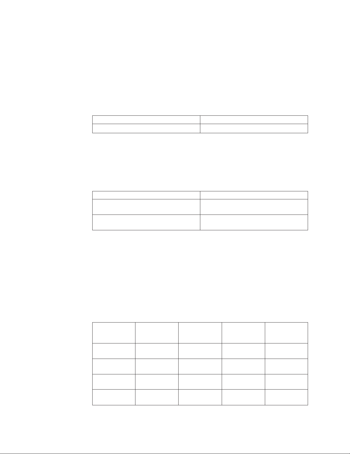
Input-voltage requirements
Ensure that your environment meets the following voltage requirements.
Voltage Frequency
200 to 240 V single phase ac 50 or 60 Hz
Power requirements for each node
Ensure that your environment meets the following power requirements.
The power that is required depends on the node type and whether the redundant
ac power feature is used.
Components Power requirements
SAN Volume Controller 2145-8F4 and 2145
UPS-1U
SAN Volume Controller 2145-8F2 and 2145
UPS-1U
520 W
520 W
For each redundant ac-power switch, add 20 W to the power requirements.
Circuit breaker requirements
The 2145 UPS-1U has an integrated circuit breaker and does not require additional
protection.
Environment requirements without redundant ac power
Ensure that your environment falls within the following ranges if you are not
using redundant ac power.
Maximum wet
Environment Temperature Altitude
Operating in
lower altitudes
Operating in
higher altitudes
Turned off 10°C to 43°C
Storing 1°C to 60°C
10°C to 35°C
(50°F to 95°F)
10°C to 32°C
(50°F to 88°F)
(50°F to 110°F)
(34°F to 140°F)
0 to 914.4 m
(0 to 3000 ft)
914.4 to 2133.6 m
(3000 to 7000 ft)
0 to 2133.6 m
(3000 to 7000 ft)
0 to 2133.6 m
(0 to 7000 ft)
Relative
humidity
8% to 80%
noncondensing
8% to 80%
noncondensing
8% to 80%
noncondensing
5% to 80%
noncondensing
bulb
temperature
23°C (74°F)
23°C (74°F)
27°C (81°F)
29°C (84°F)
2 IBM System Storage SAN Volume Controller: Models 2145-8F2 and 2145-8F4 Hardware Installation Guide
Page 27

Maximum wet
Environment Temperature Altitude
Shipping -20°C to 60°C
(-4°F to 140°F)
0 to 10668 m
(0 to 34991 ft)
Relative
humidity
5% to 100%
condensing, but
no precipitation
bulb
temperature
29°C (84°F)
Environment requirements with redundant ac power
Ensure that your environment falls within the following ranges if you are using
redundant ac power.
Maximum wet
Environment Temperature Altitude
Operating in
lower altitudes
Operating in
higher altitudes
Turned off 10°C to 43°C
Storing 1°C to 60°C
Shipping -20°C to 60°C
15°C to 32°C
(59°F to 89°F)
15°C to 32°C
(50°F to 88°F)
(50°F to 110°F)
(34°F to 140°F)
(-4°F to 140°F)
0 to 914.4 m
(0 to 3000 ft)
914.4 to 2133.6
m
(3000 to 7000 ft)
0 to 2133.6 m
(0 to 7000 ft)
0 to 2133.6 m
(0 to 7000 ft)
0 to 10668 m
(0 to 34991 ft)
Relative
humidity
20% to 80%
noncondensing
20% to 80%
noncondensing
20% to 80%
noncondensing
5% to 80%
noncondensing
5% to 100%
condensing, but
no precipitation
bulb
temperature
23°C (74°F)
23°C (74°F)
27°C (81°F)
29°C (84°F)
29°C (84°F)
Preparing your environment
The following tables list the physical characteristics of the SAN Volume Controller
2145-8F4 and SAN Volume Controller 2145-8F2 nodes.
Dimensions and weight
Ensure that space is available in a rack that is capable of supporting the node.
Height Width Depth Maximum weight
43 mm
(1.69 in.)
440 mm
(17.32 in.)
686 mm
(27 in.)
12.7 kg
(28 lb)
Additional space requirements
Ensure that space is also available in the rack for the following additional space
requirements around the node.
Additional space
Location
Left and right sides 50 mm (2 in.) Cooling air flow
Back Minimum:
requirements Reason
Cable exit
100 mm (4 in.)
Chapter 1. SAN Volume Controller overview 3
Page 28
Heat output of each SAN Volume Controller 2145-8F4 or SAN
Volume Controller 2145-8F2 node
The nodes dissipate the following maximum heat output.
Model Heat output per node
SAN Volume Controller 2145-8F4 450 W (1540 Btu per hour)
SAN Volume Controller 2145-8F2 450 W (1540 Btu per hour)
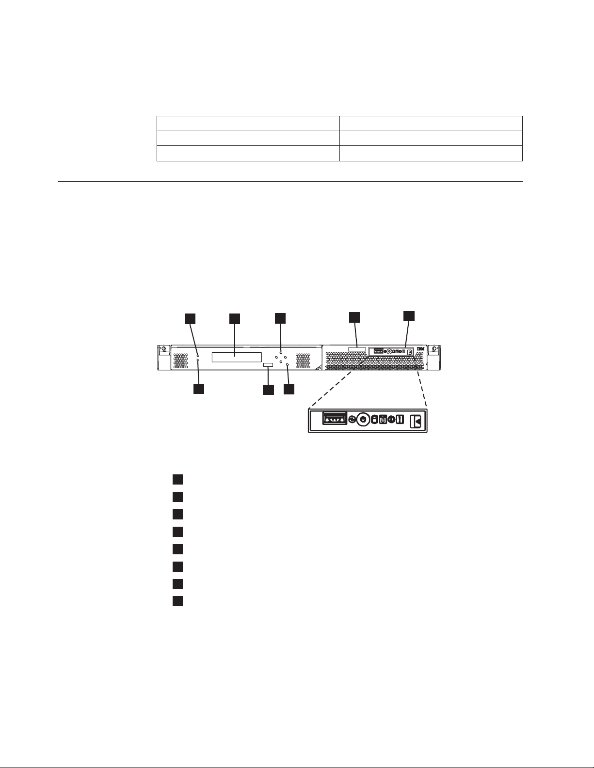
SAN Volume Controller 2145-8F4 and SAN Volume Controller 2145-8F2 controls and indicators
The controls and indicators are used for power and navigation and to indicate
information such as system activity, service and configuration options, service
controller failures, and node identification.
Figure 1 shows the controls and indicators on the front panel of the SAN Volume
Controller 2145-8F4 and SAN Volume Controller 2145-8F2.
1
8
Figure 1. SAN Volume Controller 2145-8F2 and SAN Volume Controller 2145-8F4 front-panel
assembly
1
1
Node status LED
2
Front-panel display
3
Navigation buttons
4
Serial number label
5
Operator-information panel
6
Select button
7
Node identification label
8
Error LED
2
3
6
7
4
5
svc00075
1
1
1
11
11
Node status LED
System activity is indicated through the green LED.
The node status LED provides the following system activity indicators:
Off The node is not operating as a member of a cluster.
On The node is operating as a member of a cluster.
4 IBM System Storage SAN Volume Controller: Models 2145-8F2 and 2145-8F4 Hardware Installation Guide
Page 29

1
1
1
1
Flashing
The node is dumping cache and state data to the local disk in anticipation
of a system reboot (from a pending power-off action or other controlled
restart sequence).
Front-panel display
The front-panel display shows service, configuration, and navigation information.
You can select the language that is displayed on the front panel. The display can
show both alphanumeric information and graphical information (progress bars).
The front-panel display shows configuration and service information about the
SAN Volume Controller node and the SAN Volume Controller cluster, including
the following items:
v Boot progress indicator
v Boot failed
v Charging
v Hardware boot
v Node rescue request
v Power failure
v Powering off
v Recovering
v Restarting
v Shutting down
v Error codes
v Validate WWNN?
Navigation buttons
You can use the navigation buttons to move through menus.
There are four navigational buttons that you can use to move throughout a menu:
up, down, right, and left.
Each button corresponds to the direction that you can move in a menu. For
example, to move right in a menu, press the navigation button that is located on
the right side. If you want to move down in a menu, press the navigation button
that is located on the bottom.
Note: The select button is used in tandem with the navigation buttons.
Product serial number
The node contains a SAN Volume Controller product serial number that is written
to the system board hardware. The product serial number is also printed on the
serial number label on the right side of the front panel.
This number is used for warranty and service entitlement checking and is included
in the data sent with error reports. It is essential that this number is not changed
during the life of the product. If the system board is replaced, you must follow the
system board replacement instructions carefully and rewrite the serial number on
the system board.
Chapter 1. SAN Volume Controller overview 5
Page 30

SAN Volume Controller 2145-8F4 and SAN Volume Controller 2145-8F2 operator information panel
The operator-information panel contains buttons and indicators such as the release
latch for the light path diagnostics panel, the power-control button, and LEDs that
indicate information such as system-board errors, hard-drive activity, and power
status.
Figure 2 shows the operator-information panel that is used by the SAN Volume
Controller 2145-8F4 and the SAN Volume Controller 2145-8F2 models.
5
6
8
Figure 2. SAN Volume Controller 2145-8F2 and SAN Volume Controller 2145-8F4
operator-information panel
1
Release latch for light path diagnostics panel
2
System-error LED (amber)
3
Information LED (amber)
4
Location LED (blue)
5
Hard disk drive activity LED (green)
6
Power control button
7
Power LED (green)
8
USB connector
7
4
2
3
1
svc00084
Release latch
The release latch on the SAN Volume Controller 2145-8F4 and 2145-8F2 give you
access to the light path diagnostics panel, which provides a method for
determining the location of a problem.
After pressing the release latch on the operator-information panel, you can slide
the light path diagnostics panel out to view the lit LEDs. The LEDs indicate the
type of error that has occurred. See MAP 5800: Light path for more detail.
To retract the panel, push it back into the node and snap it into place.
System-error LED
When it is lit, the system-error LED indicates that a system-board error has
occurred.
This amber LED lights up if the SAN Volume Controller hardware detects a fatal
error that requires a new field-replaceable unit (FRU).
Note: See MAP 5800: Light path to help you isolate the faulty FRU.
A system-error LED is also at the rear of the node.
6 IBM System Storage SAN Volume Controller: Models 2145-8F2 and 2145-8F4 Hardware Installation Guide
Page 31

Information-error LED
When the information-error LED is lit, a noncritical event has occurred.
Check the light path diagnostics panel and the error log. Light path diagnostics are
described in more detail in the light path maintenance analysis procedure (MAP).
Location LED
The SAN Volume Controller does not use the location LED.
Hard disk drive activity LED
When it is lit, the green hard disk drive activity LED indicates that the hard disk
drive is in use.
Hard disk drive activity is shown on the hard disk drive activity LED. For the
SAN Volume Controller 2145-8F2, hard disk drive activity is also shown on the
hard disk drive itself.
Power control button
The power control button turns on or turns off the main power to the SAN Volume
Controller.
To turn on the power, press and release the power control button. You must have a
pointed device, such as a pen, to press the button.
To turn off the power, press and release the power control button. For more
information about how to turn off the SAN Volume Controller node, see “MAP
5350: Powering off a SAN Volume Controller node” in the IBM System Storage SAN
Volume Controller Troubleshooting Guide.
Attention: When the node is operational and you press and immediately release
the power control button, the SAN Volume Controller indicates on its front panel
that it is turning off and writes its control data to its internal disk. This can take up
to five minutes. If you press the power control button but do not release it, the
node turns off immediately without the SAN Volume Controller control data being
written to disk. Service actions are then required to make the SAN Volume
Controller operational again. Therefore, during a power-off operation, do not press
and hold the power control button for more than two seconds.
Note: The 2145 UPS-1U does not turn off when the SAN Volume Controller is shut
down from the power control button.
Power LED
The green power LED indicates the power status of the SAN Volume Controller.
The power LED has the following properties:
Off One or more of the following are true:
v No power is present at the power supply input.
v The power supply has failed.
v The LED has failed.
On The SAN Volume Controller node is turned on.
Flashing
The SAN Volume Controller node is turned off, but is still connected to a
power source.
Chapter 1. SAN Volume Controller overview 7
Page 32

Note: A power LED is also at the rear of the node.
Select button
Use the select button to select an item from a menu.
The select button and navigation buttons help you to navigate and select menu
and boot options, and start a service panel test. The select button is located on the
front panel of the SAN Volume Controller, near the navigation buttons.
Node identification label
The node identification label on the front panel displays a six-digit node
identification number. Sometimes this number is called the panel name or front
panel ID.
The node identification label is the six-digit number that is input to the svctask
addnode command. It is readable by system software and is used by configuration
and service software as a node identifier. The node identification number can also
be displayed on the front-panel display when node is selected from the menu.
If the service controller assembly front panel is replaced, the configuration and
service software displays the number that is printed on the front of the
replacement panel. Future error reports contain the new number. No cluster
reconfiguration is necessary when the front panel is replaced.
Error LED
Critical faults on the service controller are indicated through the amber error LED.
The error LED has the following two states:
OFF The service controller is functioning correctly.
ON A critical service-controller failure was detected and you must replace the
service controller.
SAN Volume Controller 2145-8F4 and SAN Volume Controller 2145-8F2 rear panel indicators
The rear-panel indicators consist of LEDs that indicate the status of the
fibre-channel ports, Ethernet connection and activity, power, electrical current, and
system-board errors.
SAN Volume Controller 2145-8F4 rear panel indicators
The rear panel indicators are located on the back panel assembly.
Figure 3 on page 9 shows the rear panel indicators on the SAN Volume Controller
2145-8F4 back panel assembly.
8 IBM System Storage SAN Volume Controller: Models 2145-8F2 and 2145-8F4 Hardware Installation Guide
Page 33

1
1
3
2
1
1
Figure 3. SAN Volume Controller 2145-8F4 rear-panel indicators
4
5
6
7
svc00533
1
1
1
1
1
1
1
1
1
Fibre-channel LEDs
2
Ethernet port 1 link LED
3
Ethernet port 1 activity LED
4
Ethernet port 2 link LED
5
Ethernet port 2 activity LED
6
Power, location, and system error LEDs
7
Ac and dc LEDs
SAN Volume Controller 2145-8F2 rear panel indicators
The rear panel indicators are located on the back panel assembly.
Figure 4 shows the rear panel indicators on the SAN Volume Controller 2145-8F2
back panel assembly.
1
4
3
2
Figure 4. SAN Volume Controller 2145-8F2 rear-panel indicators
1
1
1
1
1
1
1
1
Fibre-channel LEDs
2
Ethernet port 1 link LED
3
Ethernet port 1 activity LED
4
Ethernet port 2 link LED
5
Ethernet port 2 activity LED
6
Power, location, and system error LEDs
7
Ac and dc LEDs
5
6
7
svc00529
Chapter 1. SAN Volume Controller overview 9
Page 34

Fibre-channel LEDs
The fibre-channel LEDs indicate the status of the fibre-channel ports on the SAN
Volume Controller 2145-8F4 node.
The SAN Volume Controller 2145-8F4 uses two fibre-channel LEDs per
fibre-channel port, which are arranged one above the other.The LEDs are arranged
in the same order as the ports.
The fibre-channel LEDs indicate the following link status.
Top row (link speed) Bottom row (link activity) Link status
Off Off Inactive
Off On / Blinking Active 1 Gbps
Blinking On / Blinking Active 2 Gbps
On On / Blinking Active 4 Gbps
Note: Blinking indicates I/O activity.
Figure 5 shows the fibre-channel LEDs on the SAN Volume Controller 2145-8F4.
3
2
1
Figure 5. SAN Volume Controller 2145-8F4 fibre-channel LEDs
4
svc00192
The fibre-channel LEDs are not used by the SAN Volume Controller 2145-8F2.
Ethernet link LED
The Ethernet link LED indicates that there is an active connection on the Ethernet
port.
2
2
2
2
2
There is a set of LEDs for each Ethernet connector. The top LED is the Ethernet
link LED. When it is lit, it indicates that there is an active connection on the
Ethernet port. The bottom LED is the Ethernet activity LED. When it flashes, it
indicates that data is being transmitted or received between the server and a
network device.
Power, location, and system error LEDs
The power, location, and system error LEDs are housed together on the rear of the
SAN Volume Controller next to the monitor port.
The following terms describe the power, location, and system error LEDs:
Power LED
This is the top of the three LEDs and indicates the following states:
10 IBM System Storage SAN Volume Controller: Models 2145-8F2 and 2145-8F4 Hardware Installation Guide
Page 35

Off One or more of the following are true:
v No power is present at the power supply input
v The power supply has failed
v The LED has failed
On The SAN Volume Controller is powered on.
Flashing
The SAN Volume Controller is turned off but is still connected to a
power source.
Location LED
This is the middle of the three LEDs and is not used by the SAN Volume
Controller.
System-error LED
This is the bottom of the three LEDs that indicates that a system board
error has occurred. The light path diagnostics provide more information.
Ac and dc LEDs
The ac and dc LEDs indicate whether the node is receiving electrical current.
Ac LED
1
The upper LED
present on the node.
Dc LED
The lower LED
present on the node.
next to the power supply, indicates that ac current is
2
next to the power supply, indicates that dc current is
Ac and dc LEDs on the SAN Volume Controller 2145-8F4 and the SAN Volume
Controller 2145-8F2:
The ac LED and dc LED are located on the rear of the SAN Volume Controller
2145-8F4 and the SAN Volume Controller 2145-8F2.
Figure 6 on page 12 shows the location of the ac and dc LEDs.
Chapter 1. SAN Volume Controller overview 11
Page 36

1
2
svc00105
Figure 6. SAN Volume Controller 2145-8F4 and SAN Volume Controller 2145-8F2 ac and dc
LEDs
External connectors on the SAN Volume Controller 2145-8F4 and the SAN Volume Controller 2145-8F2
The external connectors consist of PCI slots, fibre-channel, Ethernet, and serial
ports, and the power supply.
SAN Volume Controller 2145-8F4 connectors
The external connectors consist of Ethernet, serial, and fibre-channel ports, and the
power supply.
Figure 7 shows the external connectors on the SAN Volume Controller 2145-8F4
back panel assembly.
2
1
8
Figure 7. SAN Volume Controller 2145-8F4 external connectors
1
1
1
1
1
1
Fibre-channel port 1
2
Fibre-channel port 2
3
Fibre-channel port 3
4
Fibre-channel port 4
5
Power supply
7
6
4
3
5
svc00532
12 IBM System Storage SAN Volume Controller: Models 2145-8F2 and 2145-8F4 Hardware Installation Guide
Page 37

6
1
1
1
Serial connection
7
Ethernet port 2
8
Ethernet port 1
Figure 8 shows the type of connector that is located on the power supply assembly.
The connector enables you to connect the SAN Volume Controller 2145-8F4 to the
power source from the uninterruptible power supply.
Neutral
Ground
Live
Figure 8. Power connector
SAN Volume Controller 2145-8F4 ports used during service
procedures
1
1
The SAN Volume Controller 2145-8F4 contains the keyboard service port and the
monitor service port. These ports are used only during service procedures. Figure 9
provides the locations of the service ports.
1
Figure 9. Service ports of the SAN Volume Controller 2145-8F4
1
1
1
Keyboard port
2
Monitor port
2
svc00531
SAN Volume Controller 2145-8F4 ports not used during normal
operation
The SAN Volume Controller 2145-8F4 is equipped with several ports that are not
used by the SAN Volume Controller during normal operation. Figure 10 on page
14 and Figure 11 on page 14 show the ports that are not used by the SAN Volume
Controller.
Chapter 1. SAN Volume Controller overview 13
Page 38

2
1
Figure 10. Ports not used during normal operation by the SAN Volume Controller 2145-8F4
1
1
1
1
1
1
Figure 11. Ports not used on the front panel of the SAN Volume Controller 2145-8F4
System management port
2
Mouse port
3
Keyboard port
4
USB ports
5
Monitor port
1
1
USB port
3
4
5
svc00210
svc00530
SAN Volume Controller 2145-8F2 connectors
The external connectors consist of the power supply and Ethernet, fibre-channel,
and serial ports.
Figure 12 shows the external connectors on the SAN Volume Controller 2145-8F2
back panel assembly.
4
8
7
Figure 12. SAN Volume Controller 2145-8F2 external connectors
1
Power supply
2
Fibre-channel port 4
3
Serial connection
4
Fibre-channel port 3
5
Fibre-channel port 2
6
Fibre-channel port 1
7
1
Ethernet port 2
56
3
2
1
svc00528
14 IBM System Storage SAN Volume Controller: Models 2145-8F2 and 2145-8F4 Hardware Installation Guide
Page 39

8
Ethernet port 1
Figure 13 shows the type of connector that is located on the power supply
assembly. The connector enables you to connect the SAN Volume Controller
2145-8F2 to the power source from the uninterruptible power supply.
Neutral
Ground
Live
Figure 13. Power connector
SAN Volume Controller 2145-8F4 and SAN Volume Controller 2145-8F2 fibre-channel port numbers and worldwide port names
The SAN Volume Controller 2145-8F4 and SAN Volume Controller 2145-8F2
fibre-channel ports are identified by their physical port number and by a
worldwide port name (WWPN).
Figure 14 provides a view of the rear of the SAN Volume Controller 2145-8F4.
1
2
3
4
svc00177
Figure 14. The physical port numbers for the SAN Volume Controller 2145-8F4
Figure 15 provides a view of the rear of the SAN Volume Controller 2145-8F2.
4
2
1
Figure 15. The physical port numbers for the SAN Volume Controller 2145-8F2
3
svc00212
The physical port numbers identify fibre-channel cards and cable connections
when you perform service tasks. The WWPNs are used for tasks such as
fibre-channel switch configuration and to uniquely identify the devices on the
SAN.
The WWPNs are derived from the worldwide node name (WWNN) of the SAN
Volume Controller node in which the card is installed.
Chapter 1. SAN Volume Controller overview 15
Page 40

The WWNN is in the form 50050768010XXXXX, where XXXXX is initially derived
from the unit and is specific to a SAN Volume Controller node. You can change the
XXXXX value by using the front panel to facilitate service controller concurrent
replacement and to enable some concurrent upgrade operations.
The WWPNs are in the form 5005076801QXXXXX, where XXXXX is as previously
stated and Q is related to the port number as follows:
Port Value of Q
14
23
31
42
16 IBM System Storage SAN Volume Controller: Models 2145-8F2 and 2145-8F4 Hardware Installation Guide
Page 41

Chapter 2. Redundant ac-power switch
The redundant ac-power switch is an optional feature that makes the SAN Volume
Controller nodes resilient to the failure of a single power circuit. The redundant
ac-power switch is not a replacement for an uninterruptible power supply. You
must still use a uninterruptible power supply for each node.
You must connect the redundant ac-power switch to two independent power
circuits. One power circuit connects to the main power input port and the other
power circuit connects to the backup power input port. If the main power to the
SAN Volume Controller node fails for any reason, the redundant ac-power switch
automatically uses the backup power source. When power is restored, the
redundant ac-power switch automatically changes back to using the main power
source.
Place the redundant ac-power switch in the same rack as the SAN Volume
Controller node. The redundant ac-power switch logically sits between the rack
power distribution unit and the 2145 UPS-1U.
You can use a single redundant ac-power switch to power one or two SAN Volume
Controller nodes. If you use the redundant ac-power switch to power two nodes,
the nodes must be in different I/O groups. In the event that the redundant
ac-power switch fails or requires maintenance, both nodes power off. Because the
nodes are in two different I/O groups, the hosts do not lose access to the back-end
disk data.
For maximum resilience to failure, use one redundant ac-power switch to power
each SAN Volume Controller node.
E
E
E
E
E
E
Figure 16 shows a redundant ac-power switch.
svc00297
Figure 16. Photo of the redundant ac-power switch
Redundant ac power environment requirements
Ensure that your physical site meets the installation requirements for the
redundant ac-power switch.
© Copyright IBM Corp. 2003, 2008 17
Page 42

The redundant ac-power switch requires two independent power sources that are
provided through two rack-mounted power distribution units (PDUs). The PDUs
must have IEC320-C13 outlets.
The redundant ac-power switch comes with two IEC 320-C19 to C14 power cables
to connect to rack PDUs. There are no country-specific cables for the redundant
ac-power switch.
The power cable between the redundant ac-power switch and the 2145 UPS-1U is
rated at 10 A.
Redundant ac-power switch specifications
The following tables list the physical characteristics of the redundant ac-power
switch.
Dimensions and weight
Ensure that space is available in a rack that is capable of supporting the redundant
ac-power switch.
Height Width Depth Maximum weight
43 mm (1.69 in.) 192 mm (7.56 in.) 240 mm 2.6 kg (5.72 lb)
Additional space requirements
Ensure that space is also available in the rack for the side mounting plates on
either side of the redundant ac-power switch.
Location Width Reason
Left side 124 mm (4.89 in.) Side mounting plate
Right side 124 mm (4.89 in.) Side mounting plate
Heat output (maximum)
The maximum heat output that is dissipated inside the redundant ac-power switch
is approximately 20 watts (70 Btu per hour).
Cabling of redundant ac-power switch (example)
You must properly cable the redundant ac-power switch units in your
environment.
Note: While this topic provides an example of the cable connections, it does not
indicate a preferred physical location for the components.
Figure 17 on page 19 shows an example of the main wiring for a SAN Volume
Controller cluster with the redundant ac-power switch feature. The four-node
cluster consists of two I/O groups:
v I/O group 0 contains nodes A and B
v I/O group 1 contains nodes C and D
18 IBM System Storage SAN Volume Controller: Models 2145-8F2 and 2145-8F4 Hardware Installation Guide
Page 43

Figure 17. A four-node SAN Volume Controller cluster with the redundant ac-power switch
feature
1 I/O group 0
2 SAN Volume Controller node A
3 2145 UPS-1U A
4 SAN Volume Controller node B
5 2145 UPS-1U B
6 I/O group 1
7 SAN Volume Controller node C
8 2145 UPS-1U C
9 SAN Volume Controller node D
10 2145 UPS-1U D
11 Redundant ac-power switch 1
12 Redundant ac-power switch 2
13 Site PDU X (C13 outlets)
14 Site PDU Y (C13 outlets)
Chapter 2. Redundant ac-power switch 19
Page 44

The site PDUs X and Y (13 and 14) are powered from two independent power
sources.
In this example, only two redundant ac-power switch units are used, and each
power switch powers one node in each I/O group. However, for maximum
redundancy, use one redundant ac-power switch to power each node in the cluster.
20 IBM System Storage SAN Volume Controller: Models 2145-8F2 and 2145-8F4 Hardware Installation Guide
Page 45

Chapter 3. Uninterruptible power supply
The uninterruptible power supply protects a SAN Volume Controller node against
blackouts, brownouts, and power surges. The uninterruptible power supply
contains a power sensor to monitor the supply and a battery to provide power
until an orderly shutdown of the system can be performed.
SAN Volume Controller 2145-8F4 and SAN Volume Controller 2145-8F2 use the
2145 UPS-1U.
2145 UPS-1U
A 2145 UPS-1U is used exclusively to maintain data that is held in the SAN
Volume Controller dynamic random access memory (DRAM) in the event of an
unexpected loss of external power. This use differs from the traditional
uninterruptible power supply that enables continued operation of the device that it
supplies when power is lost.
With a 2145 UPS-1U, data is saved to the internal disk of the SAN Volume
Controller node. The uninterruptible power supply units are required to power the
SAN Volume Controller nodes even when the input power source is considered
uninterruptible.
Note: The uninterruptible power supply maintains continuous SAN Volume
Controller-specific communications with its attached SAN Volume Controller
nodes. A SAN Volume Controller node cannot operate without the
uninterruptible power supply. The uninterruptible power supply must be
used in accordance with documented guidelines and procedures and must
not power any equipment other than a SAN Volume Controller node.
2145 UPS-1U configuration
A 2145 UPS-1U powers one SAN Volume Controller node.
To make the SAN Volume Controller cluster more resilient against power failure,
the 2145 UPS-1U units can be connected to the redundant ac-power switch.
If a redundant ac-power switch is not used, the two uninterruptible power supply
units that power an I/O group can be connected to different, independent
electrical power sources. In this case, if a single power source fails, only one node
in the I/O group stops and the SAN Volume Controller cluster can continue to
operate although with reduced performance.
Each uninterruptible power supply must be in the same rack as the node that it
powers.
Each 2145 UPS-1U includes one power cord that connects the uninterruptible
power supply to a redundant ac-power switch, if one exists, or to a rack power
distribution unit (PDU), if one exists. The 2145 UPS-1U also includes an alternative
power cable to connect to an external power source that is specific to your
geography.
© Copyright IBM Corp. 2003, 2008 21
Page 46

Each 2145 UPS-1U is connected to a SAN Volume Controller node with a power
cable and a signal cable. To avoid the possibility of power and signal cables being
connected to different uninterruptible power supply units, these cables are
wrapped together and supplied as a single field-replaceable unit. The signal cable
enables the SAN Volume Controller node to read status and identification
information from the uninterruptible power supply.
2145 UPS-1U controls and indicators
All controls and indicators for the 2145 UPS-1U are located on the front-panel
assembly.
LOAD 1LOAD 2
1 2 3 4 5
Figure 18. 2145 UPS-1U front-panel assembly
+ -
6
7
8
1yyzvm
1 Load segment 2 indicator
2 Load segment 1 indicator
3 Alarm or Service indicator
4 On-battery indicator
5 Overload indicator
6 Power-on indicator
7 On/off button
8 Test and alarm reset button
Table 1 identifies which status and error LEDs that display on the 2145 UPS-1U
front-panel assembly relate to the specified error conditions. It also lists the
uninterruptible power supply alert-buzzer behavior.
Table 1. 2145 UPS-1U error indicators
[1] Load2 [2] Load1 [3] Alarm [4] Battery
Green (see
Note 1)
Green Amber (see
Note 2)
[5]
Overload
[6]
Power-on Buzzer Error condition
Green (see Note3)No errors; the 2145
UPS-1U was
configured by the SAN
Volume Controller
Green No errors; the 2145
UPS-1U is not yet
configured by the SAN
Volume Controller
22 IBM System Storage SAN Volume Controller: Models 2145-8F2 and 2145-8F4 Hardware Installation Guide
Page 47

Table 1. 2145 UPS-1U error indicators (continued)
[1] Load2 [2] Load1 [3] Alarm [4] Battery
Green Either on
Amber Green Beeps for
or off
Green Either on
or off
Green Either on
Flashing
red
Flashing
red
Flashing
red
Flashing
red
Flashing
amber
Flashing
amber
Flashing
amber
Amber Beeps for
or off
Green Either on
or off
Flashing
amber
Green Either on
or off
Amber Red Beeps for
Either on
or off
Either on
or off
Either on
or off
Either on
or off
Flashing
red
Flashing
red
Amber Solid on Battery test fail
Flashing
red
Flashing
Amber Green Solid on Over temperature
red
Flashing
Amber Red Green Output short circuit
red
[5]
Overload
[6]
Power-on Buzzer Error condition
The ac power is over
Flashing
red
Flashing
green
two
seconds
and then
stops
Three
beeps every
or under limit. The
uninterruptible power
supply has switched to
battery mode.
Battery undervoltage
ten seconds
Flashing
Solid on Battery overvoltage
green
Flashing
green
Solid on Output wave is
abnormal when the
charger is open, on
battery mode
Solid on The ac-power output
wave is under low
limit or above high
limit on battery mode
On battery (no ac
four
power)
seconds
and then
stops
Beeps for
two
Low battery (no ac
power)
seconds
and then
stops
Red Green Beeps for
Overload while on line
one second
and then
stops
Overload while on
one second
battery
and then
stops
Green Solid on Fan failure
Red Solid on Overload timeout
Chapter 3. Uninterruptible power supply 23
Page 48

Table 1. 2145 UPS-1U error indicators (continued)
[5]
[1] Load2 [2] Load1 [3] Alarm [4] Battery
Notes:
1. The green Load2 LED ([1]) indicates that power is being supplied to the right pair of ac-power outlets as seen
from the rear of the 2145 UPS-1U.
2. The amber Load1 LED ([2]) indicates that power is being supplied to the left pair of ac-power outlets as seen
from the rear of the 2145 UPS-1U. These outlets are not used by the SAN Volume Controller.
This LED might be illuminated during power-on sequences, but it is typically extinguished by the SAN Volume
Controller node that is attached to the 2145 UPS-1U.
3. A blank cell indicates that the light or buzzer is off.
Overload
[6]
Power-on Buzzer Error condition
Load segment 2 indicator
The load segment 2 indicator on the 2145 UPS-1U is lit (green) when power is
available to load segment 2.
When the load segment 2 indicator is green, the 2145 UPS-1U is running normally
and power is available to this segment.
Load segment 1 indicator
The load segment 1 indicator on the 2145 UPS-1U is not currently used by the
SAN Volume Controller.
Note: When the 2145 UPS-1U is configured by the SAN Volume Controller, this
load segment is disabled. During normal operation, the load segment 1
indicator is off. A “Do not use” label covers the receptacles.
Alarm
If the alarm on the 2145 UPS-1U is flashing red, maintenance is required.
If the alarm is on, go to the 2145 UPS-1U MAP to resolve the problem.
On-battery indicator
The amber on-battery indicator is on when the 2145 UPS-1U is powered by the
battery. This indicates that the main power source has failed.
If the on-battery indicator is on, go to the 2145 UPS-1U MAP to resolve the
problem.
Overload indicator
The overload indicator lights up when the capacity of the 2145 UPS-1U is
exceeded.
If the overload indicator is on, go to MAP 5250: 2145 UPS-1U repair verification to
resolve the problem.
Power-on indicator
The power-on indicator is displayed when the 2145 UPS-1U is functioning.
When the power-on indicator is a steady green, the 2145 UPS-1U is active.
24 IBM System Storage SAN Volume Controller: Models 2145-8F2 and 2145-8F4 Hardware Installation Guide
Page 49

On/off button
The on/off button turns the power on or turns the power off to the 2145 UPS-1U.
Turning on the 2145 UPS-1U
After you connect the 2145 UPS-1U to the outlet, it remains in standby mode until
you turn it on. Press and hold the on/off button until the power-on indicator is
illuminated (approximately five seconds). On some versions of the 2145 UPS-1U,
you might need a pointed device, such as a screwdriver, to press the on/off
button. A self-test is initiated that takes approximately 10 seconds, during which
time the indicators are turned on and off several times. The 2145 UPS-1U then
enters normal mode.
Turning off the 2145 UPS-1U
Press and hold the on/off button until the power-on light is extinguished
(approximately five seconds). On some versions of the 2145 UPS-1U, you might
need a pointed device, such as a screwdriver, to press the on/off button. This
places the 2145 UPS-1U in standby mode. You must then unplug the 2145 UPS-1U
to turn off the unit.
Attention: Do not turn off the uninterruptible power supply before you shut
down the SAN Volume Controller node that it is connected to. Always follow the
instructions that are provided in MAP 5350 to perform an orderly shutdown of a
SAN Volume Controller node.
Test and alarm reset button
Use the test and alarm reset button to start the self-test.
To start the self-test, press and hold the test and alarm reset button for three
seconds. This button also resets the alarm.
2145 UPS-1U connectors and switches
The 2145 UPS-1U has external connectors and dip switches.
Locations for the 2145 UPS-1U connectors and switches
Figure 19 shows the location of the connectors and switches on the 2145 UPS-1U:
1
Figure 19. 2145 UPS-1U connectors and switches
1 Main power connector
2 Communication port
3 Dip switches
4 Load segment 1 receptacles
5 Load segment 2 receptacles
2
3
4
5
svc00308
Chapter 3. Uninterruptible power supply 25
Page 50

2145 UPS-1U dip switches
Figure 20 shows the dip switches, which can be used to configure the input and
output voltage ranges. Because this function is performed by the SAN Volume
Controller software, both switches must be left in the OFF position.
ON
121 2
OFF
svc00147
Figure 20. 2145 UPS-1U dip switches
2145 UPS-1U ports not used
The 2145 UPS-1U is equipped with ports that are not used by the SAN Volume
Controller and have not been tested. Use of these ports, in conjunction with the
SAN Volume Controller or any other application that might be used with the SAN
Volume Controller, is not supported. Figure 21 shows the 2145 UPS-1U ports that
are not used.
Figure 21. Ports not used by the 2145 UPS-1U
1 USB interface port
2 Network ports
3 Load segment receptacles
2145 UPS-1U power connector
Figure 22 shows the power connector for the 2145 UPS-1U.
Neutral
Ground
Live
Figure 22. Power connector
26 IBM System Storage SAN Volume Controller: Models 2145-8F2 and 2145-8F4 Hardware Installation Guide
Page 51

Uninterruptible power-supply environment requirements
An uninterruptible power-supply environment requires that certain specifications
for the physical site of the SAN Volume Controller must be met.
2145 UPS-1U environment
All SAN Volume Controller models are supported with the 2145 UPS-1U.
2145 UPS-1U specifications
The following tables describe the physical characteristics of the 2145 UPS-1U.
2145 UPS-1U dimensions and weight
Ensure that space is available in a rack that is capable of supporting the 2145
UPS-1U.
Height Width Depth Maximum weight
44 mm
(1.73 in.)
Note: The 2145 UPS-1U package, which includes support rails, weighs 18.8 kg (41.4 lb).
Heat output
439 mm
(17.3 in.)
579 mm
(22.8 in.)
16 kg
(35.3 lb)
The 2145 UPS-1U unit produces the following approximate heat output.
Heat output during normal
Model
2145 UPS-1U 10 W (34 Btu per hour) 150 W (512 Btu per hour)
operation
Power cables for the 2145 UPS-1U
If you do not connect the 2145 UPS-1U to a rack power distribution unit (PDU) or
redundant ac-power switch, you must follow your country or region’s power
requirements to choose the appropriate power cable for the 2145 UPS-1U.
The 2145 UPS-1U is supplied with an IEC 320-C13 to C14 jumper to connect it to a
rack PDU. You can also use this cable to connect the 2145 UPS-1U to the redundant
ac-power switch.
The following table lists the power cable options for your country or region.
Country or region Length
United States of America (Chicago),
Canada, Mexico
1.8 m (6 ft) NEMA L6-15P 39M5115
Heat output during battery
operation
Connection type
(attached plug
designed for 200
-240Vac
input) Part number
Chapter 3. Uninterruptible power supply 27
Page 52

Connection type
(attached plug
designed for 200
-240Vac
Country or region Length
Bahamas, Barbados, Bermuda,
Bolivia, Brazil, Canada, Cayman
Islands, Colombia, Costa Rica,
Dominican Republic, Ecuador, El
Salvador, Guatemala, Guyana, Haiti,
Honduras, Jamaica, Japan, Korea
(South), Liberia, Mexico,
Netherlands Antilles, Nicaragua,
Panama, Peru, Philippines, Saudi
Arabia, Suriname, Taiwan, Trinidad
(West Indies), United States of
America, Venezuela
Afghanistan, Algeria, Andorra,
Angola, Austria, Belgium, Benin,
Bulgaria, Burkina Faso, Burundi,
Cameroon, Central African
Republic, Chad, Czech Republic,
Egypt, Finland, France, French
Guiana, Germany, Greece, Guinea,
Hungary, Iceland, Indonesia, Iran,
Ivory Coast, Jordan, Lebanon,
Luxembourg, Macao S.A.R. of
China, Malagasy, Mali, Martinique,
Mauritania, Mauritius, Monaco,
Morocco, Mozambique,
Netherlands, New Caledonia, Niger,
Norway, Poland, Portugal, Romania,
Senegal, Slovakia, Spain, Sudan,
Sweden, Syria, Togo, Tunisia,
Turkey, former USSR, Vietnam,
former Yugoslavia, Zaire, Zimbabwe
Antigua, Bahrain, Brunei, Channel
Islands, Hong Kong S.A.R. of China,
Cyprus, Dubai, Fiji, Ghana, India,
Iraq, Ireland, Kenya, Kuwait,
Malawi, Malaysia, Malta, Nepal,
Nigeria, Polynesia, Qatar, Sierra
Leone, Singapore, Tanzania,
Uganda, United Kingdom, Yemen,
Zambia
Argentina 2.8 m (9 ft) IRAM 2073 39M5068
Argentina, Australia, New Zealand,
Papua New Guinea, Paraguay,
Uruguay, Western Samoa
Bangladesh, Burma, Pakistan, South
Africa, Sri Lanka
Chile, Ethiopia, Italy, Libya, Somalia 2.8 m (9 ft) CEI 23-16 39M5165
People’s Republic of China 2.8 m (9 ft) GB 2099.1 39M5206
Denmark 2.8 m (9 ft) DK2-5a 39M5130
Israel 2.8 m (9 ft) SI 32 39M5172
2.8 m (9 ft) NEMA L6-15P 39M5116
2.8 m (9 ft) CEE 7-VII 39M5123
2.8 m (9 ft) BS 1363/A 39M5151
2.8 m (9 ft) AS/NZS
2.8 m (9 ft) SABS 164 39M5144
input) Part number
39M5102
3112/2000
28 IBM System Storage SAN Volume Controller: Models 2145-8F2 and 2145-8F4 Hardware Installation Guide
Page 53

Connection type
(attached plug
designed for 200
-240Vac
Country or region Length
Liechtenstein, Switzerland 2.8 m (9 ft) IEC 60884 Stnd.
input) Part number
39M5158
Sheet 416534?2
(CH Type 12)
Thailand 2.8 m (9 ft) NEMA 6-15P 39M5095
Chapter 3. Uninterruptible power supply 29
Page 54

30 IBM System Storage SAN Volume Controller: Models 2145-8F2 and 2145-8F4 Hardware Installation Guide
Page 55

Chapter 4. Installing the SAN Volume Controller 2145-8F4 or the SAN Volume Controller 2145-8F2 hardware
There are several steps that you must perform to prepare and then install the SAN
Volume Controller 2145-8F4 or the SAN Volume Controller 2145-8F2 hardware.
The following topics describe the SAN Volume Controller 2145-8F4 or the SAN
Volume Controller 2145-8F2 hardware installation tasks in the order that they
should be performed.
Note: If you are adding a new I/O group to an existing SAN Volume Controller
cluster, there is no need to turn off the existing, operating cluster nodes.
1. Prepare for the SAN Volume Controller hardware installation by confirming
that you have all the planning information and parts that you require.
2. Optionally, install and verify the redundant ac-power switch, if it is to be used
and is not already being used for a node.
3. Install the uninterruptible power supply.
4. Install the node.
5. Connect the fibre-channel and Ethernet cables to the node.
6. Connect the node to the uninterruptible power supply.
7. Verify the node.
8. Install and verify the master console, unless it is already installed. Optionally,
this step can be performed first.
After you finish these steps, the hardware installation is complete.
Optionally installing the redundant ac-power switch
Use the redundant ac-power switch to make the SAN Volume Controller cluster
more resilient to power failure.
DANGER
Multiple power cords: The product is equipped with multiple power cords.
To remove all hazardous voltages, disconnect all power cords. (L003)
1
or
2
svc00322
© Copyright IBM Corp. 2003, 2008 31
Page 56

1
2
svc00323
The following topics describe the redundant ac-power switch installation tasks in
the order that they must be performed:
1. Attach the mounting plates to the redundant ac-power switch.
2. Label the cables.
3. Connect the power input cables to the redundant ac-power switch.
4. Install the redundant ac-power switch in the rack.
5. Connect the redundant ac-power switch to the site power.
6. Test the redundant ac-power switch to ensure that it automatically switches
power supplies when the main power source fails or is restored.
Attaching the mounting plates to the redundant ac-power switch
Attach the mounting plates to the redundant ac-power switch before you label the
cables.
Perform the following steps to attach the mounting plates to the redundant
ac-power switch:
Attach each of the two mounting plates to the redundant ac-power switch using
three M3 Torx T8 head screws. Position the mounting face on the side of the
redundant ac-power switch containing the output power sockets. See Figure 23.
Figure 23. Attaching the mounting plates
Labeling the cables
You must label each end of the two redundant ac-power switch input-power cables
before you connect the input-power cables to the redundant ac-power switch.
svc00294
32 IBM System Storage SAN Volume Controller: Models 2145-8F2 and 2145-8F4 Hardware Installation Guide
Page 57

Perform the following steps to label each end of the two redundant ac-power
switch input-power cables:
1. Label the rack power-distribution end “Power source <name>, outlet <id> to
redundant ac-power switch <location> <MAIN | BACKUP> input.” For
example, “Power source D2, outlet 4 to redundant ac-power switch pos 7
MAIN input.” One cable is labeled “MAIN;” the other is labeled “BACKUP.”
2. Label the redundant ac-power switch end “redundant ac-power switch
<location> <MAIN | BACKUP> input from Power source <name>, outlet
<id>.” One cable is labeled “MAIN;” the other is labeled “BACKUP.”
Connecting the input-power cables to the redundant ac-power switch
You will find it easier to connect the input-power cables to the redundant ac-power
switch before you install the redundant ac-power switch in the rack.
Perform the following steps to connect the input-power cables to the redundant
ac-power switch:
1. Connect the main input-power cable to the redundant ac-power switch.
2. Connect the backup input-power cable to the redundant ac-power switch.
3. Secure both the redundant ac-power switch input-power cables using the clips
of the redundant ac-power switch. See Figure 24.
Figure 24. Power cable clips
Installing the redundant ac-power switch in the rack
You must install the redundant ac-power switch in the rear of the rack before you
connect the redundant ac-power switch to the site power.
Perform the following steps to install the redundant ac-power switch in the rack:
1. Use the hardware location chart to determine where to install the redundant
ac-power switch in the rack. The redundant ac-power switch can be installed
horizontally in a rack slot or vertically in one of the side slots of the rack.
2. Position the four “C” clips in the rack’s mounting bar, as shown in Figure 25 on
page 34.
Chapter 4. Installing the SAN Volume Controller 2145-8F4 or the SAN Volume Controller 2145-8F2 hardware 33
svc00291
Page 58

svc00292
Figure 25. Positioning the clips
3. Position the redundant ac-power switch in the rack first, pushing the cables
through to the front of the rack. Mount in place, as shown in Figure 26, using
the four M6 screws.
Figure 26. Positioned in rack
Connecting the redundant ac-power switch to the site power
You must connect the redundant ac-power switch to the site power before you test
the redundant ac-power switch.
Perform the following steps to connect the redundant ac-power switch to the site
power:
1. Determine a suitable cable route from the redundant ac-power switch to the
power distribution units.
2. Route the main input-power cable of the redundant ac-power switch to the
specified power distribution unit, and connect it.
3. Route the backup input-power cable of the redundant ac-power switch to the
specified power distribution unit, and connect it.
4. Verify that the redundant ac-power switch power cables are tidy. Ensure that
they do not obstruct other equipment and that they are tied in place where
necessary.
34 IBM System Storage SAN Volume Controller: Models 2145-8F2 and 2145-8F4 Hardware Installation Guide
Page 59

Testing the redundant ac-power switch
You can test the redundant ac-power switch before you continue installing other
SAN Volume Controller components. You can test the redundant ac-power switch
later if a suitable test device is not available.
You can test whether the redundant ac-power switch correctly switches between
power inputs when the main input power fails or is restored. You can either use a
volt meter to measure for voltage at the output or attach a work light, or similar
device with a C14 plug, to the redundant ac-power switch output and verify that it
remains powered when a failure is simulated on either of the inputs.
Notes:
v If you do not have a separate device to verify that there is power on the
output port of the redundant ac-power switch, you can delay this test
until you connect the redundant ac-power switch to the uninterruptible
power supply. In that case, turn on the uninterruptible power supply
(not the SAN Volume Controller node) and see if it changes to battery
power. The test fails if the uninterruptible power supply switches to
battery power for more than five seconds.
v Any transient indications of battery power can be ignored.
When the instructions say to “remove power,” you can either turn the power off if
the site power-distribution unit (PDU) has outputs that are individually switched
or remove the specified redundant ac-power switch power cable from the outlet of
the site PDU.
Note: If at any time there is no power on the output socket, ensure that the power
distribution sockets of the power source are turned on. If they are, recheck
all of the connections and decide if the redundant ac-power switch assembly,
which includes the input-power cables, is defective.
Perform the following steps to test the redundant ac-power switch:
1. Confirm that there is power at redundant ac-power switch output socket 2.
2. Confirm that there is power at redundant ac-power switch output socket 1.
3. Remove power from the main power cable to the redundant ac-power switch
and confirm that there is power at the redundant ac-power switch output 1.
4. Reconnect the main power cable.
5. Remove power from the backup power cable to the redundant ac-power switch
and confirm that there is power at the redundant ac-power switch output 1.
6. Reconnect the backup power cable and remove the monitoring device.
Note: After any failure, repeat the test phase from the start until all the tests
succeed.
Installing the 2145 UPS-1U
Before you can use the SAN Volume Controller, you need to install the
uninterruptible power supply.
Complete the following steps to install the 2145 UPS-1U:
1. Install the support rails for the 2145 UPS-1U.
2. Install the 2145 UPS-1U in the rack.
3. Install the 2145 UPS-1U cable-retention bracket.
Chapter 4. Installing the SAN Volume Controller 2145-8F4 or the SAN Volume Controller 2145-8F2 hardware 35
Page 60

Installing the support rails for the 2145 UPS-1U
You must install the support rails in the rack before installing the 2145 UPS-1U.
Complete the following prerequisites before installing the support rails:
1. Use the customer’s hardware-location chart to determine where in the rack that
the 2145 UPS-1U is to be installed.
2. At the back of the rack, observe the Electronic Industries Alliance (EIA)
positions and determine where you are going to install the 2145 UPS-1U.
Because of its weight, position the 2145 UPS-1U where it is easy to handle in
one of the lower positions in the rack.
Perform the following steps to install the support rails for the 2145 UPS-1U:
1. Open the top of the 2145 UPS-1U shipping carton. Grip the flaps on either side
of the 2145 UPS-1U.
2. Lift the 2145 UPS-1U clear of the shipping carton and place it on a flat, stable
surface with the front facing you.
3. Attach the long side of a mounting bracket 1 to each side of the 2145 UPS-1U
using four M3 × 6 screws 2 for each bracket, as shown in Figure 27.
1
2
svc00004
Figure 27. Installing the support rails for a 2145 UPS-1U into the rack
1
1
1
1
4. Loosen the assembly wing nuts (1 in Figure 28) on both rail assemblies and
adjust the rail size to the depth of your rack. After you adjust the depth,
tighten the assembly wing nuts as much as possible while still allowing some
movement.
Front
Rear
Figure 28. Adjusting the rail depth on the 2145 UPS-1U
2
1
svc00033
1 Assembly wing nuts
36 IBM System Storage SAN Volume Controller: Models 2145-8F2 and 2145-8F4 Hardware Installation Guide
Page 61

2 Wing nut
5. Select the holes in the rail where you want to position the 2145 UPS-1U.
Note: The bottom flange of the support rail must align with the EIA mark on
the rack.
6. Using two M6 × 10 screws (1 in Figure 29) and two clip nuts 2, attach the
rail to the rear of the rack. The customer’s rack might be different than the one
shown here, and if so, might require different clip nuts or fasteners.
2
1
svc00034
Figure 29. Securing the rear rail on the 2145 UPS-1U
1
1
7. Install two clip nuts (2 and 3 in Figure 30) to the front of the rack and then
attach the rail using just one M6 x 10 screw in the bottom mounting hole 1.
Figure 30. Securing the front rail on the 2145 UPS-1U
8. Repeat steps 6 and 7 for the other rail.
9. Tighten the assembly wing nuts on both rail assemblies.
Installing the 2145 UPS-1U in the rack
After you have completed the preparation procedures, you are ready to install the
2145 UPS-1U in the rack.
Chapter 4. Installing the SAN Volume Controller 2145-8F4 or the SAN Volume Controller 2145-8F2 hardware 37
Page 62

Attention: See “Safety and environmental notices” on page vii before you start
the installation process. Use the reference numbers in parentheses at the end of
each safety notice to find the matching translated notice. For the translation of the
danger, caution, and attention notices, see the IBM Systems Safety Notices.
CAUTION:
The uninterruptible power supply contains its own energy source (sealed,
lead-acid batteries). The output receptacles might carry live voltage, even when
the uninterruptible power supply is not connected to an ac supply. (11)
CAUTION:
Do not remove or unplug the input cord when the uninterruptible power supply
is turned on. Unplugging the input cord removes the safety ground from the
uninterruptible power supply and the equipment connected to the
uninterruptible power supply. (12)
CAUTION:
To reduce the risk of fire or electric shock, install the uninterruptible power
supply in a temperature- and humidity-controlled indoor environment, free of
conductive contaminants. Ambient temperature must not exceed 40°C (104°F). Do
not operate near water or excessive humidity (95% maximum). (13)
CAUTION:
To avoid any hazard from the rack tipping forward when devices are installed,
observe all safety precautions for the rack into which you are installing the
device.
Perform the following steps to install the 2145 UPS-1U in the rack.
Note: You might have already completed steps 3 on page 39 through 6 on page 40
if you used the Read Me First pamphlet, which is included with the 2145
UPS-1U.
1. Stand at the front of the rack and place the back of the 2145 UPS-1U onto the
support rails, and then slide the 2145 UPS-1U into the rack.
CAUTION:
The 2145 UPS-1U weighs 16 kg (35.3 lb). If you feel unsure about lifting the
uninterruptible power supply to its location in the rack, seek assistance or
remove the battery to reduce its weight.
1
1
2. At the front of the 2145 UPS-1U, install the two mounting screws (M6x10) 1
as shown in Figure 31 on page 39.
38 IBM System Storage SAN Volume Controller: Models 2145-8F2 and 2145-8F4 Hardware Installation Guide
Page 63

1
Figure 31. Mounting screws for the 2145 UPS-1U
svc00008
1
1
1
3. If you have not already connected the internal battery connector, remove the
2145 UPS-1U front panel, shown in Figure 32, by pushing the panel to the left
and then pulling it forward.
svc00063
Figure 32. Removing the 2145 UPS-1U front panel
4. Remove the protective label from the internal battery connector (shown in
Figure 33 on page 40).
Chapter 4. Installing the SAN Volume Controller 2145-8F4 or the SAN Volume Controller 2145-8F2 hardware 39
Page 64

svc00062
Figure 33. The 2145 UPS-1U internal battery connector with protective tape
5. Connect the internal battery connector (shown in Figure 34). Each end of the
keyed connector has two wires: one red (+) and one black (−). Align the
connector so that the two red wires are joined together and the two black wires
are joined together.
Note: A small amount of arcing might occur when connecting the batteries.
This is normal and does not damage the unit or present any safety
concerns.
Figure 34. The 2145 UPS-1U internal-battery connector
6. Reinstall the front panel. You might first need to move the sliding section on
the front of the 2145 UPS-1U to the closed position.
7. At the back of the 2145 UPS-1U, plug the 2145 UPS-1U main-power connector
into the power socket (1 in Figure 35 on page 41). The 2145 UPS-1U is in
standby mode, so all indicators are off.
It is recommended that each 2145 UPS-1U for an I/O group is connected to a
different power source.
40 IBM System Storage SAN Volume Controller: Models 2145-8F2 and 2145-8F4 Hardware Installation Guide
svc00061
Page 65

1
Figure 35. 2145 UPS-1U (rear view)
2
3
1 Main power connector
2 Communication port
3 Load segment 2 receptacle
Attention: Ensure that you comply with the following requirements:
v The voltage supplied to the 2145 UPS-1U must be 200 - 240 V single phase.
v The frequency supplied must be 50 or 60 Hz.
Notes:
a. The 2145 UPS-1U has an integrated circuit breaker and does not
require external protection.
b. The 2145 UPS-1U is intended to maintain power on SAN Volume
Controller nodes until data can be saved to the local hard-disk drive.
Only SAN Volume Controller nodes can be plugged into the 2145
UPS-1U or the SAN Volume Controller cluster malfunctions.
8. Press and hold the on/off button (7 in Figure 36) for approximately five
seconds. You might need a pointed device, such as a screwdriver, to press the
on/off button. The front panel indicators cycle through a startup sequence
while the 2145 UPS-1U conducts a self-test.
1yz09b
LOAD 1LOAD 2
1 2 3 4 5
Figure 36. 2145 UPS-1U front-panel assembly
+ -
6
7
8
1yyzvm
When the self-test is complete, the power-on indicator 6 and the load
indicators (1 and 2) illuminate to indicate that power is being supplied by
the 2145 UPS-1U. The 2145 UPS-1U is now in normal mode, and is charging its
battery. If the battery indicator 4 is on and the alarm is sounding, the voltage
range setting might not be correct. When a SAN Volume Controller is
connected to the 2145 UPS-1U, the SAN Volume Controller automatically
adjusts the voltage range setting. Take no action for this alarm condition unless
it persists for more than five minutes after a SAN Volume Controller has been
connected to this 2145 UPS-1U and turned on.
9. Repeat all of these steps to install additional 2145 UPS-1U units.
Chapter 4. Installing the SAN Volume Controller 2145-8F4 or the SAN Volume Controller 2145-8F2 hardware 41
Page 66

Installing the 2145 UPS-1U cable-retention bracket
The 2145 UPS-1U cable-retention bracket ensures that the power cable connection
between the 2145 UPS-1U and the SAN Volume Controller node is stable.
1
1
Install the bracket after you install the power and signal cable assembly that was
supplied with the node to connect the 2145 UPS-1U and the node.
You can attach the bracket by performing the following steps:
1. Install the power cable into the rightmost power outlet on the rear of the 2145
UPS-1U.
2. Remove the bracket and the two screws (shown in Figure 37) from the
packaging.
svc00201
Figure 37. 2145 UPS-1U power cable-retention bracket hardware
3. Place the bracket over the power outlets on the right rear of the 2145 UPS-1U,
so that the two screw holes line up.
4. Position the bracket with the power cable protruding through the rightmost slot
in the bracket.
5. Secure the bracket in place with one screw on each side, as shown in Figure 38.
svc00200
Figure 38. 2145 UPS-1U power cable-retention bracket
42 IBM System Storage SAN Volume Controller: Models 2145-8F2 and 2145-8F4 Hardware Installation Guide
Page 67

Installing the SAN Volume Controller 2145-8F2 or the SAN Volume Controller 2145-8F4
There are several steps that you must perform to install the SAN Volume
Controller 2145-8F2 or the SAN Volume Controller 2145-8F4 nodes.
Installing the SAN Volume Controller 2145-8F2 or the SAN Volume Controller
2145-8F4 consists of the following tasks:
1. Installing the support rails in the rack cabinet.
2. Installing the SAN Volume Controller 2145-8F2 or the SAN Volume Controller
2145-8F4.
3. Connecting the SAN Volume Controller 2145-8F2 or the SAN Volume Controller
2145-8F4 to the uninterruptible power supply.
4. Installing the cable retention bracket on the SAN Volume Controller 2145-8F4.
Installing the support rails for the SAN Volume Controller 2145-8F4 or the SAN Volume Controller 2145-8F2
You must install the support rails that hold the SAN Volume Controller 2145-8F4
or the SAN Volume Controller 2145-8F2.
When you are ready to install the support rails, use the customer’s
hardware-location chart and the Electronic Industries Alliance (EIA) positions on
the rack to determine where in the rack that the SAN Volume Controller node is to
be installed.
Perform the following steps to install the support rails:
1. Check the labels on the support rails. Each rail has a label that indicates which
is the front end of the rail and whether the rail is for the left or right side of
the rack. Perform this procedure for both rails.
1
2. Put your index finger against the side of the latch-lever,
put your thumb against the front of the latch-lock
2
.
in Figure 39, and
2
1
Figure 39. Retracting the latch-lock carrier
1
Latch-lever
Chapter 4. Installing the SAN Volume Controller 2145-8F4 or the SAN Volume Controller 2145-8F2 hardware 43
Page 68

2
Latch-lock
2
3. Gently push the latch lock
lever
1
toward the far end of the rail (Figure 40). The latch-lock carrier
away from the rail as you move the latch
assembly slides against the spring tension.
2
121
23nl1c
Figure 40. Opening the front latch-lock carrier assembly
1
Latch-lever
2
Latch-lock
4. Continue to slide the latch-lock carrier for approximately 13 mm (0.5 in). The
latch-lever engages a hole in the back bracket assembly and holds the
latch-lock carrier in the retracted position.
1
5. Push the back rail bracket
(Figure 41) toward the front of the rail until it
stops. The rail is now at its shortest adjustment.
Figure 41. Opening the back latch-lock carrier assembly
1
Latch-lever
44 IBM System Storage SAN Volume Controller: Models 2145-8F2 and 2145-8F4 Hardware Installation Guide
Page 69

2
Latch-lock
3
Back rail bracket
6. Place the front end of the left rail in the rack cabinet. Align the top of the
1
front bracket
(Figure 42) with the required EIA marking that is on the
rack.
2
1
3
Figure 42. Installing the front end of the rail
1
Front bracket
2
Rack-mounting flange
3
Locating pins
3
7. Align the locating pins
with the holes that are in the rack-mounting
flange.
2
8. Push the latch lock
(Figure 43 on page 46) away from the rail to release
the carrier. The latch-lock carrier slides toward the front of the rack and the
locating pins project through the holes that are in the front flange and in the
front rail bracket.
Important: Ensure that the locating pins are fully extended through the front
rail bracket.
Chapter 4. Installing the SAN Volume Controller 2145-8F4 or the SAN Volume Controller 2145-8F2 hardware 45
Page 70

2
1
Figure 43. Closing the latch-lock carrier assembly
1
Latch-lever
2
Latch-lock
9. Push the back rail bracket toward the rear of the rack and align the locating
pins with the rack-mounting flange.
2
10. Push the latch lock
carrier slides toward the rear of the rack, and the locating pins project through
the holes that are in the rear flange and in the rear rail bracket.
Important: Ensure that the locating pins are fully extended through the rear
rail bracket.
11. On the rear of each rail, press the blue release tab and slide the shipping
bracket off the slide rail. Store the shipping bracket for further use.
away from the rail to release the carrier. The latch-lock
Installing the SAN Volume Controller in a rack
After installing the support rails, you can install the SAN Volume Controller in a
rack.
Installing the SAN Volume Controller 2145-8F2 or the SAN Volume Controller 2145-8F4 in a rack
After installing the support rails, you can install the SAN Volume Controller
2145-8F4 or the SAN Volume Controller 2145-8F2 in the rack.
CAUTION:
To avoid any hazard from the rack tipping forward when devices are installed,
observe all safety precautions for the rack into which you are installing the
device.
46 IBM System Storage SAN Volume Controller: Models 2145-8F2 and 2145-8F4 Hardware Installation Guide
Page 71

Perform the following steps to install the SAN Volume Controller 2145-8F2 or the
SAN Volume Controller 2145-8F4 node in the rack:
1. Stand at the front of the rack and place the back of the node onto the support
rails, as low in the rack as possible.
2. Slide the node fully into the rack.
The node snaps into place.
3. Repeat this procedure for each node that needs to be installed.
Tip: If you have available space, leave a 1U space between each node to
improve the air circulation in the rack.
Connecting the SAN Volume Controller 2145-8F2 or the SAN Volume Controller 2145-8F4 to the 2145 UPS-1U
Connect the SAN Volume Controller to the 2145 UPS-1U to protect your data in
the event of an unexpected loss of external power.
Note: To make the SAN Volume Controller cluster more resilient to power failure,
the 2145 UPS-1U units can be connected to the redundant ac-power switch.
If a redundant ac-power switch is not used, you can connect the two
uninterruptible power supply units that are powering an I/O group to
different, independent electrical power sources. If a single power source
fails, the SAN Volume Controller cluster can then continue to operate with
reduced performance.
Before you begin this task, see the completed customer’s cable-connection table,
which is described in the IBM System Storage SAN Volume Controller Planning Guide
and can be downloaded from www.ibm.com/storage/support/2145.
Use the information in this table to identify the 2145 UPS-1U unit to which this
node is to be connected.
Perform the following steps to connect the SAN Volume Controller to the 2145
UPS-1U:
1. At the back of the SAN Volume Controller 2145-8F2 or the SAN Volume
Controller 2145-8F4, plug the combined power and serial cable into the power
2
connector
. See Figure 44 on page 48.
Chapter 4. Installing the SAN Volume Controller 2145-8F4 or the SAN Volume Controller 2145-8F2 hardware 47
Page 72

1
2
4
5
Figure 44. Connecting the SAN Volume Controller 2145-8F2 power cable to the 2145
UPS-1U
1
Fibre-channel ports
2
Power connector
3
Serial connector
4
Ethernet ports
5
Main power connector
6
Communication port
7
Load segment 2 receptacle
3
6
ATTENTION
CONNECTONLY IBM SAN VOLUME
CONTROLLERSTO THESE OUTLETS.
SEE SAN VOLUME CONTROLLER
INSTALLATIONGUIDE.
7
2. Place the other end of the power cable into the rightmost load segment 2
7
receptacle
on the 2145 UPS-1U.
DANGER
You have already switched on the 2145 UPS-1U. The output sockets of the
2145 UPS-1U are live.
svc00083
3. Plug the signal cable into the serial connector
3
located on the SAN Volume
Controller 2145-8F4 or the SAN Volume Controller 2145-8F2.
4. Place the other end of the signal cable into the communication port
2145 UPS-1U.
The SAN Volume Controller power is now connected to the 2145 UPS-1U.
Installing the SAN Volume Controller 2145-8F4 cable retention bracket
The cable retention bracket ensures that the SAN Volume Controller 2145-8F4 node
does not mistakenly become unplugged from the uninterruptible power supply.
Install the SAN Volume Controller 2145-8F4 cable retention bracket after you install
the node in the rack.
To attach the bracket to the support rail, perform the following steps:
1. Install the power cable into the power supply.
48 IBM System Storage SAN Volume Controller: Models 2145-8F2 and 2145-8F4 Hardware Installation Guide
6
on the
Page 73

2. Insert the bracket onto the power cable so that the power cable is held by the
slot on the end of the bracket. Figure 45 provides a view of how to align the
cable retention bracket with the cable.
svc00175
Figure 45. Attaching the cable retention bracket to the SAN Volume Controller 2145-8F4
power cable
3. Position the cable retention bracket against the support rail and attach the
bracket onto the slot in the rear of the rail. Figure 46 provides a view of the
cable retention bracket that is attached to the SAN Volume Controller 2145-8F4.
svc00174
Figure 46. SAN Volume Controller 2145-8F4 with cable-retention bracket attached
Connecting the SAN Volume Controller 2145-8F4 or the SAN Volume Controller 2145-8F2 to the SAN and to the Ethernet network
Before you connect the SAN Volume Controller 2145-8F4 or the SAN Volume
Controller 2145-8F2 to the SAN, you must connect the Ethernet and fibre-channel
cables.
Before you begin this task, refer to the user’s cable connection table to find out
where to connect the Ethernet and fibre-channel cables.
To connect the SAN Volume Controller 2145-8F4 or the SAN Volume Controller
2145-8F2 to the SAN and to the Ethernet network, perform the following steps:
5
1. Connect the Ethernet cable to Ethernet port 1
Figure 48 on page 50.
Chapter 4. Installing the SAN Volume Controller 2145-8F4 or the SAN Volume Controller 2145-8F2 hardware 49
in Figure 47 on page 50 or
Page 74

Attention: You must use only Ethernet port 1 on the SAN Volume Controller.
The software is configured only for Ethernet port 1.
2. Connect the other end of the Ethernet cable to the proper connector on the
Ethernet hub or switch.
1
2
3
4
5
Figure 47. Connectors at the back of the SAN Volume Controller 2145-8F4
1
Fibre-channel port 1
2
Fibre-channel port 2
3
Fibre-channel port 3
4
Fibre-channel port 4
5
Ethernet port 1
1
Figure 48. Connectors at the back of the SAN Volume Controller 2145-8F2
1
Ethernet port 1
2
Low-profile, dual-port fibre-channel host bus adapter (HBA) with ports
2
3
1 and 2 (left to right)
3
Full-height, dual-port fibre-channel HBA with ports 3 and 4 (left to
right)
svc00178
svc00090
Attention: When routing the fibre-channel cables, do not tighten the cable
straps or bend the cables to a radius smaller than 76 mm (3 in.).
3. Connect the fibre-channel cables to the fibre-channel ports as required by the
user’s configuration.
4. Connect the other ends of the fibre-channel cables to the proper connectors of
the fibre-channel switches.
Verifying the SAN Volume Controller 2145-8F2 or the SAN Volume Controller 2145-8F4 installation
You must verify the SAN Volume Controller installation after the installation has
completed.
50 IBM System Storage SAN Volume Controller: Models 2145-8F2 and 2145-8F4 Hardware Installation Guide
Page 75

This task shows you how to verify the installation after you install the SAN
Volume Controller in the rack and connect it to the uninterruptible power supply,
the storage area network (SAN), and the Ethernet.
Note: If at any point the SAN Volume Controller does not operate as described,
see MAP 5000 in the IBM System Storage SAN Volume Controller
Troubleshooting Guide, unless a different maintenance analysis procedure
(MAP) is specified.
Perform the following steps to verify installation:
1. Press the SAN Volume Controller power-control button. Because the button is
recessed, you might need a pointed device, such as a screwdriver, to press the
power-control button. Verify that the green power LED is lit. If the LED is not
illuminated, see MAP 5000: Start in the IBM System Storage SAN Volume
Controller Troubleshooting Guide to repair the problem.
Note: You do not need to install any software. The node boots automatically.
Verify that the node is booting without error. If it boots without error, either
the Charging, Recovering,ortheCluster: message is displayed in the first
line of the front-panel display.
2. Press and hold the select button for five seconds. The check light comes on
and a display test is performed. Check that all display cells light and that a
bar scrolls horizontally and vertically across the display. When the display test
is complete, the check light goes off and a button test is started.
3. Press the up, down, left, and right buttons to verify that they are working.
Figure 49 shows four examples of what the front panel should display when
you press the buttons. After you finish testing the buttons, press and hold the
select button for five seconds to exit the test.
Figure 49. Front-panel display when push buttons are pressed
4. If the Charging or Recovering message is displayed on the front-panel display,
press the select button to switch to the menu. The menu continues to be
displayed while you press the buttons on the front panel. If you do not press
any buttons within 60 seconds, the menu changes to display the charging
progress. You can switch the front-panel display to the menu at any time by
pressing the select button again.
5. Press and release the up button or down button until the Node: option is
displayed on the first line of the front-panel display.
6. Verify that the node number that is displayed on the second line of the
front-panel display is the same as the node number that is printed on the
front panel of the node. Figure 50 on page 52 shows how the node number is
Chapter 4. Installing the SAN Volume Controller 2145-8F4 or the SAN Volume Controller 2145-8F2 hardware 51
Page 76

displayed on the front panel. If the node number is not the same, contact the
IBM Support Center.
Node:
xxxxxx
Figure 50. Node number
7. Press and release the up button or down button until the Node: option is
displayed on the first line of the front-panel display. The second line of the
front-panel display in Figure 51 shows the message Inactive. This message
indicates that, although an Ethernet connection is available, it cannot yet be
used.
Ethernet:
Inactive
Figure 51. Ethernet mode
8. Press and release the up button or down button until the FC Port-1 option
shows in the display.
9. Check whether the second line of the front-panel display shows the message
Active.IfActive is not shown on the second line, go to MAP 5600: Fibre
channel in the IBM System Storage SAN Volume Controller Troubleshooting Guide
to repair the fault.
10. If you are installing a SAN Volume Controller 2145-8F2 node, go to step 16. If
you are installing a SAN Volume Controller 2145-8F4 node, go to step 11.
11. Press and hold the down button.
12. Press and release the select button.
13. Release the down button. The operational speed of the fibre-channel link is
displayed. Use the cable connection table that is provided by the customer to
verify that the fibre-channel link is operating at the expected speed. If the
operational speed does not match the expected speed, go to MAP 5600: Fibre
channel in the IBM System Storage SAN Volume Controller Troubleshooting Guide
to repair the fault.
14. Press the select button to return to the fibre-channel status display.
15. Press the right button to display each port in turn and ensure that the port is
active and the speed is correct. Go to step 18 on page 53
16. Press and release the left or right button to display the other port options.
Check whether for each port, the second line of the front-panel display shows
the message Active.IfActive is not shown for any port, go to “MAP 5600:
Fibre channel” in the IBM System Storage SAN Volume Controller Service Guide
to repair the fault.
17. If the configuration data table provided by the user indicates that the SAN
Volume Controller nodes are to be operated at 1 Gbps, follow these steps:
a. Press and hold the down button.
b. Press and release the select button.
c. Release the down button.
52 IBM System Storage SAN Volume Controller: Models 2145-8F2 and 2145-8F4 Hardware Installation Guide
Page 77

The second line of the front-panel display shows the current fibre-channel
speed setting of the node. Press the up or down button until 1 Gbps is
displayed and then press the select button. This changes the fibre-channel
speed for all ports on this node to 1 Gbps.
18. If you want to select a language other than English, perform the following
steps:
a. Press the up or down button until Select Language? is displayed.
b. Press the select button.
c. Press the left or right button until the required language is displayed.
d. Press the select button.
If the battery needed to be charged, the Charging or Recovering message is
replaced by the Cluster: message when the battery is fully charged. The
progress bar no longer displays. The installation of the SAN Volume
Controller hardware is now complete. No software installation is required.
Continue with the instructions in the IBM System Storage SAN Volume
Controller Software Installation and Configuration Guide to create, if necessary, a
new SAN Volume Controller cluster and to add the nodes into a SAN Volume
Controller cluster.
Chapter 4. Installing the SAN Volume Controller 2145-8F4 or the SAN Volume Controller 2145-8F2 hardware 53
Page 78

54 IBM System Storage SAN Volume Controller: Models 2145-8F2 and 2145-8F4 Hardware Installation Guide
Page 79

Appendix. Accessibility
Accessibility features help a user who has a physical disability, such as restricted
mobility or limited vision, to use software products successfully.
Features
These are the major accessibility features in the SAN Volume Controller Console:
v You can use screen-reader software and a digital speech synthesizer to hear what
is displayed on the screen. The following screen reader has been tested:
Window-Eyes v6.1.
v You can operate all features using the keyboard instead of the mouse.
v You can change the initial delay and repeat rate of the up and down buttons to
two seconds when you use the front panel of the SAN Volume Controller to set
or change an IPv4 address. This feature is documented in the applicable sections
of the SAN Volume Controller publications.
Navigating by keyboard
You can use keys or key combinations to perform operations and initiate many
menu actions that can also be done through mouse actions. You can navigate the
SAN Volume Controller Console and help system from the keyboard by using the
following key combinations:
v To traverse to the next link, button, or topic, press Tab inside a frame (page).
v To expand or collapse a tree node, press → or ←, respectively.
v To move to the next topic node, press V or Tab.
v To move to the previous topic node, press ^ or Shift+Tab.
v To scroll all the way up or down, press Home or End, respectively.
v To go back, press Alt+←.
v To go forward, press Alt+→.
v To go to the next frame, press Ctrl+Tab.
v To move to the previous frame, press Shift+Ctrl+Tab.
v To print the current page or active frame, press Ctrl+P.
v To select, press Enter.
Accessing the publications
You can view the publications for the SAN Volume Controller in Adobe Portable
Document Format (PDF) using the Adobe Acrobat Reader. The PDFs are provided
at the following Web site:
www.ibm.com/storage/support/2145
© Copyright IBM Corp. 2003, 2008 55
Page 80

56 IBM System Storage SAN Volume Controller: Models 2145-8F2 and 2145-8F4 Hardware Installation Guide
Page 81

Notices
This information was developed for products and services offered in the U.S.A.
IBM may not offer the products, services, or features discussed in this document in
other countries. Consult your local IBM representative for information on the
products and services currently available in your area. Any reference to an IBM
product, program, or service is not intended to state or imply that only that IBM
product, program, or service may be used. Any functionally equivalent product,
program, or service that does not infringe any IBM intellectual property right may
be used instead. However, it is the user’s responsibility to evaluate and verify the
operation of any non-IBM product, program, or service.
IBM may have patents or pending patent applications covering subject matter
described in this document. The furnishing of this document does not give you
any license to these patents. You can send license inquiries, in writing, to:
IBM Director of Licensing
IBM Corporation
North Castle Drive
Armonk, NY 10504-1785
U.S.A.
For license inquiries regarding double-byte (DBCS) information, contact the IBM
Intellectual Property Department in your country or send inquiries, in writing, to:
IBM World Trade Asia Corporation
Licensing
2-31 Roppongi 3-chome, Minato-ku
Tokyo 106-0032, Japan
The following paragraph does not apply to the United Kingdom or any other
country where such provisions are inconsistent with local law:
INTERNATIONAL BUSINESS MACHINES CORPORATION PROVIDES THIS
PUBLICATIONS ″AS IS″ WITHOUT WARRANTY OF ANY KIND, EITHER
EXPRESS OR IMPLIED, INCLUDING, BUT NOT LIMITED TO, THE IMPLIED
WARRANTIES OF NON-INFRINGEMENT, MERCHANTABILITY OR FITNESS
FOR A PARTICULAR PURPOSE. Some states do not allow disclaimer of express or
implied warranties in certain transactions, therefore, this statement may not apply
to you.
This information could include technical inaccuracies or typographical errors.
Changes are periodically made to the information herein; these changes will be
incorporated in new editions of the publication. IBM may make improvements
and/or changes in the product(s) and/or the program(s) described in this
publication at any time without notice.
Any references in this information to non-IBM Web sites are provided for
convenience only and do not in any manner serve as an endorsement of those Web
sites. The materials at those Web sites are not part of the materials for this IBM
product and use of those Web sites is at your own risk.
© Copyright IBM Corp. 2003, 2008 57
Page 82

IBM may use or distribute any of the information you supply in any way it
believes appropriate without incurring any obligation to you.
Licensees of this program who wish to have information about it for the purpose
of enabling: (i) the exchange of information between independently created
programs and other programs (including this one) and (ii) the mutual use of the
information which has been exchanged, should contact:
IBM Corporation
Almaden Research
650 Harry Road
Bldg 80, D3-304, Department 277
San Jose, CA 95120-6099
U.S.A.
Such information may be available, subject to appropriate terms and conditions,
including in some cases, payment of a fee.
The licensed program described in this document and all licensed material
available for it are provided by IBM under terms of the IBM Customer Agreement,
IBM International Program License Agreement or any equivalent agreement
between us.
Any performance data contained herein was determined in a controlled
environment. Therefore, the results obtained in other operating environments may
vary significantly. Some measurements may have been made on development-level
systems and there is no guarantee that these measurements will be the same on
generally available systems. Furthermore, some measurement may have been
estimated through extrapolation. Actual results may vary. Users of this document
should verify the applicable data for their specific environment.
Information concerning non-IBM products was obtained from the suppliers of
those products, their published announcements or other publicly available sources.
IBM has not tested those products and cannot confirm the accuracy of
performance, compatibility or any other claims related to non-IBM products.
Questions on the capabilities of non-IBM products may be addressed to the
suppliers of those products.
All statements regarding IBM’s future direction or intent are subject to change or
withdrawal without notice, and represent goals and objectives only.
This information is for planning purposes only. The information herein is subject to
change before the products described become available.
This information contains examples of data and reports used in daily business
operations. To illustrate them as completely as possible, the examples include the
names of individuals, companies, brands, and products. All of these names are
fictitious and any similarity to the names and addresses used by an actual business
enterprise is entirely coincidental.
COPYRIGHT LICENSE:
This information contains sample application programs in source language, which
illustrate programming techniques on various operating platforms. You may copy,
modify, and distribute these sample programs in any form without payment to
IBM, for the purposes of developing, using, marketing or distributing application
58 IBM System Storage SAN Volume Controller: Models 2145-8F2 and 2145-8F4 Hardware Installation Guide
Page 83

Trademarks
programs conforming to the application programming interface for the operating
platform for which the sample programs are written. These examples have not
been thoroughly tested under all conditions. IBM, therefore, cannot guarantee or
imply reliability, serviceability, or function of these programs.
If you are viewing this information softcopy, the photographs and color
illustrations may not appear.
IBM, the IBM logo, and ibm.com are trademarks or registered trademarks of
International Business Machines Corp., registered in many jurisdictions worldwide.
Other product and service names might be trademarks of IBM or other companies.
A current list of IBM trademarks is available on the Web at Copyright and
trademark information at www.ibm.com/legal/copytrade.shtml.
Adobe and the Adobe logo are either registered trademarks or trademarks of
Adobe Systems Incorporated in the United States, and/or other countries.
Intel, Intel logo, Intel Xeon, and Pentium are trademarks or registered trademarks
of Intel Corporation or its subsidiaries in the United States and other countries.
Java and all Java-based trademarks and logos are trademarks of Sun Microsystems,
Inc. in the United States, other countries, or both.
Linux is a registered trademark of Linus Torvalds in the United States, other
countries, or both.
Microsoft, Windows, Windows NT, and the Windows logo are trademarks of
Microsoft Corporation in the United States, other countries, or both.
UNIX is a registered trademark of The Open Group in the United States and other
countries.
Other company, product, or service names may be trademarks or service marks of
others.
Electronic emission notices
The following electronic emission statements apply to this product. The statements
for other products that are intended for use with this product are included in their
accompanying documentation.
Federal Communications Commission (FCC) statement
Ensure that you are familiar with the Federal Communications Commission (FCC)
statement.
This equipment has been tested and found to comply with the limits for a Class A
digital device, pursuant to Part 15 of the FCC Rules. These limits are designed to
provide reasonable protection against harmful interference when the equipment is
operated in a commercial environment. This equipment generates, uses, and can
radiate radio frequency energy and, if not installed and used in accordance with
the instruction manual, might cause interference to radio communications.
Notices 59
Page 84

Operation of this equipment in a residential area is likely to cause harmful
interference, in which case the user will be required to correct the interference at
his own expense.
Properly shielded and grounded cables and connectors must be used in order to
meet FCC emission limits. Neither the provider nor the manufacturer is
responsible for any radio or television interference caused by using other than
recommended cables and connectors or by unauthorized changes or modifications
to this equipment. Unauthorized changes or modifications could void the user’s
authority to operate the equipment.
This device complies with Part 15 of FCC Rules. Operation is subject to the
following two conditions: (1) this device might not cause harmful interference, and
(2) this device must accept any interference received, including interference that
might cause undesired operation.
Industry Canada compliance statement
This Class A digital apparatus complies with IECS-003.
Avis de conformité à la réglementation d’Industrie Canada
Cet appareil numérique de la classe A est conforme à la norme NMB-003 du
Canada.
New Zealand compliance statement
Ensure that you are familiar with the New Zealand compliance statement.
This is a Class A product. In a domestic environment this product might cause
radio interference, in which event the user might be required to take adequate
measures.
European Union EMC Directive conformance statement
Ensure that you are familiar with the European Union (EU) statement.
This product is in conformity with the protection requirements of EU council
directive 2004/108/EC on the approximation of the laws of the Member States
relating to electromagnetic compatibility. IBM cannot accept responsibility for any
failure to satisfy the protection requirements resulting from a nonrecommended
modification of the product, including the fitting of non-IBM option cards.
This product has been tested and found to comply with the limits for Class A
Information Technology Equipment according to European Standard EN 55022. The
limits for Class A equipment were derived for commercial and industrial
environments to provide reasonable protection against interference with licensed
communication equipment.
Attention: This is a Class A product. In a domestic environment this product may
cause radio interference in which case the user may be required to take adequate
measures.
Ensure that you use properly shielded and grounded cables and connectors in
order to reduce interference to radio and TV communications and to other
electrical or electronic equipment. Such cables and connectors are available from
IBM authorized dealers. IBM cannot accept responsibility for any interference
caused by using other than recommended cables and connectors.
60 IBM System Storage SAN Volume Controller: Models 2145-8F2 and 2145-8F4 Hardware Installation Guide
Page 85

European community contact:
IBM Technical Regulations
Pascalstr. 100, Stuttgart, Germany 70569
Telephone: 0049 (0)711 785 1176
Fax: 0049 (0)711 785 1283
E-mail: tjahn@de.ibm.com
Germany compliance statement
Deutschsprachiger EU Hinweis:
Hinweis für Geräte der Klasse A EU-Richtlinie zur Elektromagnetischen
Verträglichkeit
Dieses Produkt entspricht den Schutzanforderungen der EU-Richtlinie
2004/108/EG zur Angleichung der Rechtsvorschriften über die elektromagnetische
Verträglichkeit in den EU-Mitgliedsstaaten und hält die Grenzwerte der EN 55022
Klasse A ein.
Um dieses sicherzustellen, sind die Geräte wie in den Handbüchern beschrieben zu
installieren und zu betreiben. Des Weiteren dürfen auch nur von der IBM
empfohlene Kabel angeschlossen werden. IBM übernimmt keine Verantwortung für
die Einhaltung der Schutzanforderungen, wenn das Produkt ohne Zustimmung der
IBM verändert bzw. wenn Erweiterungskomponenten von Fremdherstellern ohne
Empfehlung der IBM gesteckt/eingebaut werden.
EN 55022 Klasse A Geräte müssen mit folgendem Warnhinweis versehen werden:
“Warnung: Dieses ist eine Einrichtung der Klasse A. Diese Einrichtung kann im
Wohnbereich Funk-Störungen verursachen; in diesem Fall kann vom Betreiber
verlangt werden, angemessene Maßnahmen zu ergreifen und dafür
aufzukommen.“
Deutschland: Einhaltung des Gesetzes über die
elektromagnetische Verträglichkeit von Geräten
Dieses Produkt entspricht dem “Gesetz über die elektromagnetische Verträglichkeit
von Geräten (EMVG)“. Dies ist die Umsetzung der EU-Richtlinie 2004/108/EG in
der Bundesrepublik Deutschland.
Zulassungsbescheinigung laut dem Deutschen Gesetz über die
elektromagnetische Verträglichkeit von Geräten (EMVG) (bzw. der
EMC EG Richtlinie 2004/108/EG) für Geräte der Klasse A
Dieses Gerät ist berechtigt, in Übereinstimmung mit dem Deutschen EMVG das
EG-Konformitätszeichen - CE - zu führen.
Verantwortlich für die Konformitätserklärung des EMVG ist die IBM Deutschland
GmbH, 70548 Stuttgart.
Generelle Informationen:
Das Gerät erfüllt die Schutzanforderungen nach EN 55024 und EN 55022 Klasse
A.
Notices 61
Page 86

Japanese Voluntary Control Council for Interference (VCCI) statement
People’s Republic of China Class A Electronic Emission
Statement
International Electrotechnical Commission (IEC) statement
This product has been designed and built to comply with (IEC) Standard 950.
United Kingdom telecommunications requirements
This apparatus is manufactured to the International Safety Standard EN60950 and
as such is approved in the U.K. under approval number NS/G/1234/J/100003 for
indirect connection to public telecommunications systems in the United Kingdom.
Korean Class A Electronic Emission Statement
Taiwan Class A compliance statement
62 IBM System Storage SAN Volume Controller: Models 2145-8F2 and 2145-8F4 Hardware Installation Guide
Page 87

European Contact Information
This topic contains the product service contact information for Europe.
European Community contact:
IBM Technical Regulations
Pascalstr. 100, Stuttgart, Germany 70569
Tele: 0049 (0)711 785 1176
Fax: 0049 (0)711 785 1283
e-mail: mailto:tjahn@de.ibm.com
Taiwan Contact Information
This topic contains the product service contact information for Taiwan.
IBM Taiwan Product Service Contact Information:
IBM Taiwan Corporation
3F, No 7, Song Ren Rd., Taipei Taiwan
Tel: 0800-016-888
f2c00790
Notices 63
Page 88

64 IBM System Storage SAN Volume Controller: Models 2145-8F2 and 2145-8F4 Hardware Installation Guide
Page 89

Index
Numerics
2145 UPS-1U
alarm 24
cable retention bracket 42
circuit breakers 25
configuration 21
connectors 25
controls and indicators on the front
panel 22
description of parts 25
dip switches 25
environment 27
installation steps 35
installing in the rack 38
internal battery connector 38
Load segment 1 indicator 24
Load segment 2 indicator 24
on-battery indicator 24
on/off button 25
overload indicator 24
ports not used 25
power cables 27
power-on indicator 24
service indicator 24
support rails 36
test and alarm-reset button 25
unused ports 25
2145-8F2 node
features 1
SAN Volume Controller 2
2145-8F4 node
features 1
SAN Volume Controller 2
A
about this guide xiii
ac and dc LEDs 11
ac power switch, cabling 18
accessibility
keyboard 55
repeat rate of up and down
buttons 55
shortcut keys 55
attaching mounting plates 32
B
back panel assembly
SAN Volume Controller 2145-8F2
connectors 14
indicators 9
SAN Volume Controller 2145-8F4
connectors 12
indicators 8
battery
2145 UPS-1U, connecting 38
bracket
cable retention
2145 UPS-1U 42
bracket (continued)
cable retention (continued)
SAN Volume Controller
2145-8F4 48
buttons, navigation 5
C
cable retention bracket
2145 UPS-1U 42
SAN Volume Controller 2145-8F4 48
cables
2145 UPS-1U
power requirements 27
connecting to the redundant ac-power
switch 33
redundant ac-power switch 33
Canadian electronic emission notice 60
circuit breakers
2145 UPS-1U 25
connecting
2145 UPS-1U 47
cables, input-power 33
redundant ac-power switch
cables 33
to site power 34
connectors
2145 UPS-1U 25
SAN Volume Controller 2145-8F2 14
SAN Volume Controller 2145-8F4 12
contact information
European 63
Taiwan 63
controls and indicators on the front panel
2145 UPS-1U
alarm 24
illustration 22
Load segment 1 indicator 24
Load segment 2 indicator 24
on-battery indicator 24
on/off button 25
overload indicator 24
power-on indicator 24
test and alarm-reset button 25
front-panel display 5
SAN Volume Controller
navigation buttons 5
node status LED 4
select button 8
SAN Volume Controller 2145-8F2
error LED 8
illustration 4
operator information panel 6
SAN Volume Controller 2145-8F4
illustration 4
operator information panel 6
D
danger notices
redundant ac power switch 31
Deutschsprachiger EU Hinweis 61
display on front panel
overview 5
disposal
product xiii
E
electronic emission notices
Avis de conformité à la
réglementation d’Industrie
Canada 60
Deutschsprachiger EU Hinweis 61
European Union (EU) 60
Federal Communications Commission
(FCC) 59
French Canadian 60
Germany 61
Industry Canada 60
International Electrotechnical
Commission (IEC) 62
Japanese Voluntary Control Council
for Interference (VCCI) 62
Korean 62
New Zealand 60
People’s Republic of China 62
Taiwan 62
United Kingdom 62
EMC statement, People’s Republic of
China 62
environmental notices vii, xi
error LED 8
Ethernet
link LED 10
SAN Volume Controller 2145-8F2 49
SAN Volume Controller 2145-8F4 49
European contact information 63
European Union (EU), EMC Directive
conformance statement 60
examples
redundant ac power switch
cabling 18
external device safety check viii
F
FCC (Federal Communications
Commission) electronic emission
notice 59
Federal Communications Commission
(FCC) electronic emission notice 59
fibre-channel
LEDs 10
French Canadian electronic emission
notice 60
front panel
2145 UPS-1U 22
© Copyright IBM Corp. 2003, 2008
65
Page 90

front panel (continued)
display 5
ID 8
G
Germany electronic emission compliance
statement 61
H
hard disk drive activity LED 7
hazards vii, x
I
identification
label, node 8
IEC (International Electrotechnical
Commission) electronic emission
notice 62
indicators and controls on the front panel
2145 UPS-1U
alarm 24
illustration 22
Load segment 1 indicator 24
Load segment 2 indicator 24
on-battery indicator 24
on/off button 25
overload indicator 24
power-on indicator 24
test and alarm-reset button 25
SAN Volume Controller
navigation buttons 5
node status LED 4
select button 8
SAN Volume Controller 2145-8F2
error LED 8
illustration 4
operator information panel 6
SAN Volume Controller 2145-8F4
illustration 4
operator information panel 6
indicators on the rear panel
ac and dc LEDs 11
Ethernet
link LED 10
fibre-channel LEDs 10
power, location, and system-error
LEDs 10
information
center xiv
error LED 7
inspections, safety
external device check viii
internal device check ix
SAN Volume Controller vii
uninterruptible power supply x
installation
verifying
SAN Volume Controller
2145-8F2 51
SAN Volume Controller
2145-8F4 51
installing
2145 UPS-1U 38
installing (continued)
cable retention bracket
2145 UPS-1U 42
SAN Volume Controller
2145-8F4 48
overview xix
redundant ac power switch
attaching the mounting plates 32
steps 31
redundant ac-power switch
connecting the input-power
cables 33
connecting to the site power 34
in the rack 33
labeling the cables 33
testing 35
SAN Volume Controller 2145-8F2
checklist 31
in a rack 46
support rails 43
SAN Volume Controller 2145-8F4
checklist 31
in a rack 46
support rails 43
steps
SAN Volume Controller
2145-8F2 43
SAN Volume Controller
2145-8F4 43
support rails
2145 UPS-1U 36
SAN Volume Controller
2145-8F2 43
SAN Volume Controller
2145-8F4 43
internal device safety check ix
International Electrotechnical Commission
(IEC) electronic emission notice 62
J
Japanese electronic emission notice 62
K
keyboard 55
Korean electronic emission statement 62
L
labeling cables 33
LEDs
ac and dc 11
Ethernet
link 10
fibre-channel 10
hard disk drive activity 7
information-error 7
location 7, 10
power 7, 10
rear panel indicators 8, 9
SAN Volume Controller 2145-8F2 9
SAN Volume Controller 2145-8F4 8
system-error 6, 10
legal notices 57
Load segment 1 indicator 24
Load segment 2 indicator 24
location LED 7
M
mounting plates
redundant ac power switch 32
N
navigation
buttons 5
New Zealand electronic emission
statement 60
node status LED 4
nodes
identification label 8
non-IBM Alteration form ix
not used
2145 UPS-1U ports 25
location LED 10
O
on/off button 25
operator information panel
hard disk drive activity LED 7
information-error LED 7
location LED 7
SAN Volume Controller 2145-8F2 6
SAN Volume Controller 2145-8F4 6
operator-information panel
power control button 7
power LED 7
system-error LED 6
output power
sockets 32
overload indicator 24
overview
installing xix
redundant ac-power switch 17
SAN Volume Controller 1
P
panel
front 5
name 8
operator information
SAN Volume Controller
2145-8F2 6
SAN Volume Controller
2145-8F4 6
rear
SAN Volume Controller
2145-8F2 9
SAN Volume Controller
2145-8F4 8
PDU (power distribution unit) 27
People’s Republic of China, electronic
emission statement 62
physical characteristics
2145 UPS-1U 27
redundant ac-power switch 18
66 IBM System Storage SAN Volume Controller: Models 2145-8F2 and 2145-8F4 Hardware Installation Guide
Page 91

physical characteristics (continued)
SAN Volume Controller 2145-8F2
connectors 14
SAN Volume Controller 2145-8F4
connectors 12
ports
not used
2145 UPS-1U 25
SAN Volume Controller
2145-8F4 12
power
cables
2145 UPS-1U 27
country or region 27
control button 7
distribution unit (PDU) 27
requirements
SAN Volume Controller
2145-8F2 2
SAN Volume Controller
2145-8F4 2
site, connecting to 34
power LED 7
preparing
uninterruptible power supply
environment 27
R
Read Me First pamphlet 38
rear panel indicators
SAN Volume Controller 2145-8F2 9
SAN Volume Controller 2145-8F4 8
redundant ac power switch
cabling 18
danger notices 31
examples 18
installing
attaching the mounting plates 32
steps 31
redundant ac-power switch
cables 33
connecting 33
input-power cables 33
to the site power 34
environment preparation 18
installing
in the rack 33
labeling the cables 33
testing 35
mounting 33
overview 17
power cables 27
specifications 18
related information xiv
requirements
2145 UPS-1U 21
power cables 27
redundant ac-power switch 27
retention bracket
SAN Volume Controller 2145-8F4 48
S
safety notices vii
SAN Volume Controller
checking grounding ix
hardware 1
installing
overview xix
minimum requirements 1
overview 1
software
overview 1
SAN Volume Controller 2145-8F2
air temperature 2
connecting
ethernet 49
to a SAN 49
to the 2145 UPS-1U 47
connectors 14
controls and indicators on the front
panel 4
dimensions and weight 2
features 1
fibre-channel port number 15
heat output 2
humidity 2
indicators and controls on the front
panel 4
installation, verifying 51
installing
checklist 31
in a rack 46
operator information panel 6
operator-information panel
release latch 6
overview 1
product characteristics 2
rear panel indicators 9
release latch 6
specifications 2
support rails 43
weight and dimensions 2
SAN Volume Controller 2145-8F4
air temperature 2
cable retention bracket 48
connecting
ethernet 49
to a SAN 49
to the 2145 UPS-1U 47
connectors 12
controls and indicators on the front
panel 4
dimensions and weight 2
features 1
fibre-channel
LEDs 10
port number 15
heat output 2
humidity 2
indicators and controls on the front
panel 4
indicators on the rear panel
fibre-channel LEDs 10
installation, verifying 51
installing
checklist 31
in a rack 46
LEDs
fibre-channel 10
operator information panel 6
SAN Volume Controller 2145-8F4
(continued)
operator-information panel
release latch 6
overview 1
product characteristics 2
rear panel indicators 8
release latch 6
specifications 2
support rails 43
weight and dimensions 2
SAN Volume Controller library
related publications xiv
serial number 5
shortcut keys 55
site power
redundant ac-power switch
connecting 34
testing 35
uninterruptible power supply
testing 35
sockets
output power 32
software
overview 1
specifications
redundant ac-power switch 18
static-sensitive devices xi
status
2145 UPS-1U 21
support rails
2145 UPS-1U 36
SAN Volume Controller 2145-8F2 43
SAN Volume Controller 2145-8F4 43
switches
2145 UPS-1U 25
redundant ac power 17
system-error LED 6
T
Taiwan
contact information 63
electronic emission notice 62
test and alarm-reset button 25
testing redundant ac-power switch 35
trademarks 59
U
uninterruptible power supply
2145 UPS-1U
configuration 21
controls and indicators 22
environment 27
overview 21
power cables 27
checking grounding ix
configuration 21
overview 21
preparing environment 27
United Kingdom electronic emission
notice 62
unused ports
2145 UPS-1U 25
SAN Volume Controller 2145-8F4 12
Index
67
Page 92

V
verifying
installation
SAN Volume Controller
2145-8F2 51
SAN Volume Controller
2145-8F4 51
W
Web sites xvii
who should read this guide xiii
68 IBM System Storage SAN Volume Controller: Models 2145-8F2 and 2145-8F4 Hardware Installation Guide
Page 93

Readers’ Comments — We’d Like to Hear from You
IBM System Storage SAN Volume Controller
Models 2145-8F2 and 2145-8F4
Hardware Installation Guide
Version 4.3.1
Publication No. GC27-2221-00
We appreciate your comments about this publication. Please comment on specific errors or omissions, accuracy,
organization, subject matter, or completeness of this book. The comments you send should pertain to only the
information in this manual or product and the way in which the information is presented.
For technical questions and information about products and prices, please contact your IBM branch office, your
IBM business partner, or your authorized remarketer.
When you send comments to IBM, you grant IBM a nonexclusive right to use or distribute your comments in any
way it believes appropriate without incurring any obligation to you. IBM or any other organizations will only use
the personal information that you supply to contact you about the issues that you state on this form.
Comments:
Thank you for your support.
Send your comments to the address on the reverse side of this form.
If you would like a response from IBM, please fill in the following information:
Name Address
Company or Organization
Phone No. E-mail address
Page 94

___________________________________________________________________________________________________
Readers’ Comments — We’d Like to Hear from You
GC27-2221-00
_________________________________________________________________________________________
Fold and Tape Please do not staple Fold and Tape
NO POSTAGE
NECESSARY
IF MAILED IN THE
UNITED STATES
Cut or Fold
Along Line
BUSINESS REPLY MAIL
FIRST-CLASS MAIL PERMIT NO. 40 ARMONK, NEW YORK
POSTAGE WILL BE PAID BY ADDRESSEE
International Business Machines Corporation
Information Development
Department 61C
9032 South Rita Road
Tucson, Arizona 85775-4401
_________________________________________________________________________________________
Fold and Tape Please do not staple Fold and Tape
GC27-2221-00
Cut or Fold
Along Line
Page 95

Page 96

Printed in USA
GC27-2221-00
 Loading...