

Page 1

IBM SAN Fibre Channel Switch
2109 Model S16 Installation and Service
Guide
The IBM License Agreement for Machine Code is included
in this book. Carefully read the agreement. By using this
product you agree to abide by the terms of this agreement
and applicable Copyright Laws.
SC26-7352-01
Page 2

Page 3

IBMSANFibreChannelSwitch
IBM
2109 Model S16 Installation and Service
Guide
SC26-7352-01
Page 4

Note:
Before using this information and the product it supports, read the information in “Safety and environmental notices” on
page xi and “Notices” on page 131.
Second Edition (December 2000)
This edition replaces SC26-7352-00.
Publications are not stocked at the address given below. If you want additional IBM publications, ask your IBM
representative or write to the IBM branch office serving your locality.
A form for your comments is provided at the back of this publication. If the form has been removed, address your
comments to:
International Business Machines Corporation
RCF Processing Department
Dept. G26/Bldg. 050-3
5600 Cottle Road
San Jose, CA 95193-0001
U.S.A.
FAX: 1-800-426-6209
You can also send your comments electronically to: starpubs@us.ibm.com
When you send information to IBM, you grant IBM a nonexclusive right to use or distribute the information in any
way it believes appropriate without incurring any obligation to you.
© Copyright International Business Machines Corporation 1999, 2000. All rights reserved.
US Government Users Restricted Rights – Use, duplication or disclosure restricted by GSA ADP Schedule Contract
with IBM Corp.
Page 5

Contents
Figures ...........................vii
Tables ............................ix
Safety and environmental notices .................xi
Translated safety notices .....................xi
Disposing of products.......................xi
About this book ........................xiii
Who should use this book.....................xiii
Where to start ........................xiii
Limited vocabulary ......................xiii
Ordering publications ......................xiii
Product library ........................xiii
Related publications ......................xiv
Web sites..........................xiv
Chapter 1. Introduction......................1
Switch features .........................1
Performance .........................2
Manageability .........................2
System components .......................2
GBICs ...........................2
Power supply .........................3
Fibre-channel cable connections ..................4
Front panel..........................5
Diagnostics overview .......................7
Verifying a power-on self-test (POST) ................7
Running diagnostics ......................7
Loop (FL) connections .....................8
||
Chapter 2. Customer planning ...................9
Chapter 3. Installing the switch ..................19
Pre-installation checklist .....................19
Installing the switch .......................20
Tabletop installation ......................20
Rack-mount installation .....................20
Installing the optional power supply .................24
Installing GBICs ........................25
Setting the IP address ......................26
Setting the IP address using the Ethernet port ............27
Setting the IP address from the front panel .............28
Switch installation verification ..................31
Code upgrade procedure .....................31
Upgrade procedure .......................31
Downloading firmware from a UNIX
Downloading firmware using a Microsoft
®
host ..............31
®
Windows NT operating system 32
Chapter 4. Maintenance action plans ................33
Problem determination start map ..................33
System reported error .....................33
Service reference table ......................35
© Copyright IBM Corp. 1999, 2000 iii
Page 6

Action codes and recommended actions ..............35
Chapter 5. Replacing FRUs....................45
Parts catalog .........................45
Replacing the power supply ....................45
Tools that are required .....................46
Removing a power supply....................46
Installing a power supply ....................47
Replacing a GBIC module.....................47
Tools that are required .....................47
Removing a GBIC module....................47
Installing a GBIC module ....................47
Replacing a fan assembly .....................48
Tools that are required .....................48
Removing a fan assembly....................48
Installing a fan assembly ....................49
Replacing the system board assembly ................49
Tools that are required .....................49
Removing the system board ...................49
Installing the system board ...................50
Replacing the chassis with touchpad .................50
Tools that are required .....................50
Removing the old chassis ....................51
Installing the new chassis ....................51
Verifying switch repair ......................51
Verifying a repair that did not require turning the switch off........52
Verifying a repair that required turning the switch off ..........52
||
||
||
||
||
||
||
||
||
||
||
||
||
||
||
||
||
||
||
||
||
||
Chapter 6. Optional features ...................53
Fabric Watch .........................53
Threshold behavior models ...................54
Installing Fabric Watch .....................55
Installing Fabric Watch through Telnet ...............55
Installing Fabric Watch through the IBM StorWatch Specialist.......56
Fabric Watch overview .....................56
Telnet commands overview ...................57
Telnet commands .......................58
Remote Switch .........................62
Introducing the Remote Switch ..................62
Installing the Remote Switch ...................62
Installing through Telnet.....................63
Installing through the IBM StorWatch Specialist ............63
Extended Fabrics ........................64
Introducing Extended Fabrics ..................64
Installing Extended Fabrics ...................64
Installing through Telnet.....................64
Installing through the IBM StorWatch Specialist ............65
Using Extended Fabrics ....................65
Configuring Extended Fabrics ..................65
Accessing through the Telnet interface ...............66
Chapter 7. Management tools ...................69
||
||
||
||
Switch management methods ...................69
Hardware setup for switch management ...............70
Setting switch IP address using the front panel ............71
Setting the IP address using the Ethernet port ............71
iv IBM SAN Fibre Channel Switch: 2109 Model S16 Installation and Service Guide
Page 7

||
||
||
||
Setting the IP address .....................73
Managing with Telnet ......................73
Default user name ......................73
Changing passwords......................74
Managing with SNMP ......................74
SNMP transports .......................76
||
||
Managing using the management server ...............78
Using the management server ..................79
syslog daemon .........................79
Introduction .........................79
syslogd support .......................80
Error message format .....................80
Message classification .....................81
Power-on self-test (POST).....................82
Chapter 8. Zoning overview ...................85
Appendix A. Specifications....................87
General specifications ......................87
Fabric management specifications..................87
Optical port specifications .....................88
Environmental specifications ....................88
Power supply specifications ....................89
Appendix B. Diagnostics.....................91
Diagnostic overview .......................91
Isolating a system fault .....................91
Removing power .......................91
Service action for error messages .................91
POST tests .........................91
Diagnostic tests ........................92
Test menu .........................92
Running diagnostics from the front panel ..............92
Front panel switch menus ....................94
Running diagnostics using Telnet.................101
||
||
||
||
||
||
||
Appendix C. Error messages ..................117
System error message formats ..................117
Diagnostic error message formats .................118
Error message numbers .....................119
Repair action code meanings for diagnostic error messages........121
Diagnostic error messages ....................122
System error messages .....................125
Notices ...........................131
Trademarks..........................131
Electronic emission statements ..................132
Federal Communications Commission (FCC) statement ........132
Industry Canada compliance statement ..............132
European Community compliance statement ............132
Germany compliance statement .................133
Japanese Voluntary Control Council for Interference (VCCI) class 1
statement ........................134
Korean Government Ministry of Communication (MOC) statement ....134
Taiwan class A compliance statement ...............134
IBM license agreement for Machine Code ..............134
Contents v
Page 8

Statement of limited warranty ...................135
Production status ......................135
IBM warranty for Machines ...................135
Warranty service.......................136
Extent of warranty ......................136
Limitation of liability......................137
||
Glossary ..........................139
Index ............................145
vi IBM SAN Fibre Channel Switch: 2109 Model S16 Installation and Service Guide
Page 9

Figures
1. Front panel of the 2109 Model S16 Switch ......................1
2. Short wavelength (SWL) laser fiber-optic GBIC module (P/N and labeling vary) ........3
3. Long wavelength (LWL) laser fiber-optic GBIC module (P/N and labeling vary) ........3
4. Power supplies ................................4
5. Dual SC fiber-optic plug connector .........................5
6. Front panel functionality.............................5
7. Moving slide ................................22
8. Mounting the moving portion of slide and locking ears to the switch ............22
9. Mounting the fixed portion of the rail and the locking ears to the rack ...........23
10. Inserting slides into the rack rails .........................24
11. 2109 model S16 with two power supplies ......................25
12. GBIC ...................................26
13. GBIC swing handle ..............................26
14. Ethernet port connector ............................27
15. Front panel - operator display and control buttons...................28
16. Front panel of the 2109 Model S16 Switch .....................33
17. Generated Telnet messages when a power supply is turned off and removed ........46
18. Power supply handle .............................47
19. IBM GBIC module ..............................47
20. Fan assembly ................................48
21. System board assembly ............................49
22. Chassis with touchpad.............................51
||
23. Example of range threshold: temperature (Celsius) ..................54
||
24. Example of rising and falling threshold: Error rate ...................55
||
25. Methods for managing the switch .........................70
||
26. Front panel — operator display and control buttons ..................71
||
27. Front panel of the 2109 Model S16 Switch .....................72
||
28. MIB tree ..................................75
29. Example of a no memory error generated by the shell .................81
30. syslogd support ...............................82
31. Example syslog configuration file entry .......................82
32. Example syslog configuration file entry .......................82
33. A fabric with three zones ............................86
34. Front panel functionality ............................93
35. Select menu ................................93
36. Menu hierarchy ...............................94
37. Switch setup to run crossPortTest.........................98
38. System memory test .............................98
39. ramTest ..................................99
40. portLoopbackTest command example .......................99
41. portRegTest command example .........................99
42. Push button command example .........................100
43. spinSilk command example ..........................100
44. Switch offline command example ........................101
45. Switch online command example ........................101
46. camTest command example ..........................102
47. centralMemoryTest command example ......................103
48. cmemRetentionTest command example ......................103
49. cmiTest command example ..........................103
50. crossPortTest command example ........................106
51. diagClearError command example ........................106
52. diagDisablePost command example .......................107
53. diagEnablePost command example .......................107
© Copyright IBM Corp. 1999, 2000 vii
Page 10

54. diagShow command example..........................108
55. portLoopbackTest command example .......................109
56. portRegTest command example .........................110
57. ramTest command example ..........................110
58. setGbicMode 1 command example ........................111
59. setGbicMode 0 command example ........................111
60. sramRetentionTest command example ......................114
61. supportShow command example ........................115
||
62. errShow command example ..........................118
viii IBM SAN Fibre Channel Switch: 2109 Model S16 Installation and Service Guide
Page 11

Tables
1. Cabling connections ..............................4
2. Control buttons ................................5
3. Front panel LED status indicators .........................6
4. Offline and Online tests .............................7
5. Offline and online test .............................8
6. Example of a planning worksheet for a 2109 switch ..................9
||
7. Blank of a planning worksheet for a 2109 switch ...................11
||
8. Example of a configuration worksheet for a 2109 switch ................12
||
9. Blank of a port configuration worksheet for a 2109 switch ................13
||
10. Example of a zone definitions worksheet ......................14
||
11. Blank of a zone definitions worksheet .......................15
||
12. Zone configuration worksheet example.......................16
||
13. Blank of a zone configuration worksheet ......................17
||
14. Pre-installation checklist ............................19
15. Control buttons ...............................28
16. Service reference table ............................35
17. Action code and recommended actions ......................35
18. Field replaceable units (FRUs) list ........................45
19. Fabric Watch Telnet commands .........................57
||
20. Comparison of management access methods ....................69
||
21. Default user name ..............................73
||
syslogd
22.
23. Switch specifications .............................87
24. Fabric management specifications ........................87
25. Environmental specifications ..........................88
26. Power supply requirements ...........................89
27. POST tests .................................91
28. Control buttons ...............................93
29. Offline and online diagnostic tests ........................94
30. centralMemoryTest example...........................95
||
31. cmemRetention test example ..........................96
||
32. cmiTest example ...............................96
||
33. Offline and online diagnostic tests ........................102
34. diagShow command field descriptions ......................108
35. portLoopbackTest command field descriptions....................109
36. spinSilk command example 1..........................112
37. spinsilk command example 2 ..........................113
38. Probable failure actions ............................118
||
39. Error message code defined ..........................119
||
40. Action codes and recommended actions......................121
||
41. Diagnostic error messages...........................122
||
42. System error messages ............................125
||
message classifications .........................81
© Copyright IBM Corp. 1999, 2000 ix
Page 12

x IBM SAN Fibre Channel Switch: 2109 Model S16 Installation and Service Guide
Page 13

Safety and environmental notices
Safety notices are printed throughout this manual. Danger notices warn you of
conditions or procedures that can result in death or severe personal injury. Caution
notices warn you of conditions or procedures that can cause personal injury that is
neither lethal nor extremely hazardous. Attention notices warn you of conditions or
procedures that can cause damage to machines, equipment, or programs.
Translated safety notices
The translation of the safety notices in this manual are contained in a separate
manual. See the
translation of any danger and caution notices.
Disposing of products
This unit may contain batteries. Remove and discard these batteries, or recycle
them, according to local regulations.
IBM External Devices Safety Information Manual
, SA26-7003, for a
© Copyright IBM Corp. 1999, 2000 xi
Page 14

xii IBM SAN Fibre Channel Switch: 2109 Model S16 Installation and Service Guide
Page 15

About this book
This book describes how to install and maintain the IBM SAN Fibre Channel Switch
2109 Model S16.
Who should use this book
This book is intended for trained service representatives and service providers who
act as the primary level of field hardware service support to help solve and
diagnose hardware problems on the IBM SAN Fibre Channel Switch 2109 Model
S16.
This book also assists the customer in planning the installation of the 2109 Model
S16 switch.
|
|
“Chapter 2. Customer planning” on page 9 contains the customer planning
worksheets that are required to be filled out before installing the 2109 switches.
Before using this book, you must know how to service the switch hardware, and
how to analyze, isolate, report, and resolve problems. You must also know how to
safely work with electrical components. Throughout this book, the term “switch”
applies to any IBM 2109 switch, unless the reference is to a specific model.
Where to start
When performing any service action on the switch, follow the directions given in
“Chapter 4. Maintenance action plans” on page 33. This ensures that you use the
correct remove, replace, or repair procedures for this machine, including the correct
procedures to turn the power on and off. Failure to follow these instructions can
cause damage to the machine.
Limited vocabulary
This book uses a specific range of words so that the text can be understood by IBM
service support representatives in countries where English is not the primary
language.
Ordering publications
All of the publications listed in the switch product library are shipped as appropriate
with their respective switches. You can also order additional copies of each
publication.
Product library
The IBM 2109 Model S16 is an IBM SAN Fibre Channel Switch product. See the
following publications for more information about the switch:
v
IBM SAN Fibre Channel Switch 2109 Model S16 User’s Guide
This book introduces the IBM 2109 Model S16 Switch, and its features. It also
provides information about using the IBM StorWatch
Specialist, setting up zoning, and methods for managing the IBM 2109 Model
S16 Switch remotely.
IBM SAN Fibre Channel Switch 2109 Model S16 Installation and Service Guide
v
SC26-7352.
© Copyright IBM Corp. 1999, 2000 xiii
, SC26-7351
™
SAN Fibre Channel Switch
,
Page 16

This book introduces the product and lists the features you can order. It also
provides procedures for installing, configuring, and servicing the IBM 2109 Model
S16 Switch.
IBM External Devices Safety Information
v
This book provides translations of the Danger and Caution notices used in IBM
2109 switch publications.
Related publications
v
Electrical Safety for IBM Customer Engineers
v
Fibre Channel Standards
Web sites
For additional information about storage products, see our Web site at:
www.ibm.com/storage/fcswitch
For detailed information about the fibre-channel standards, see the fibre-channel
association Web site at:
www.fibrechannel.com
, SA26-7003.
, S229-8124
xiv IBM SAN Fibre Channel Switch: 2109 Model S16 Installation and Service Guide
Page 17
Chapter 1. Introduction
The IBM SAN Fibre Channel Switch 2109 Model S16 is a 16-port, fibre-channel,
switch. The IBM 2109 Model S16 Switch consists of a system board with
connectors for supporting up to 16 ports, and a fabric operating system for creating
and managing a fabric. A
scheme for a fibre channel.
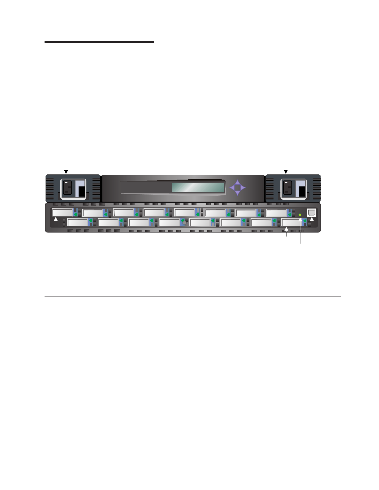
Figure 1 shows the front view of the 2109 Model S16 Switch. Ports are numbered
sequentially starting with zero for the left-most port. The switch faceplate includes a
silk screen imprint of the port numbers. Up to two power supplies are supported;
these are shown to the left and right of the switch ports in Figure 1.
fabric
is an active, intelligent, nonshared interconnection
Power supply 2
Port 0
Figure 1. Front panel of the 2109 Model S16 Switch
Switch features
The switch is a high-performance, fibre-channel, switch with the following features:
Simple
Easy setup and configuration. After the power-on self-test (POST), you
need only to add the internet protocol (IP) address to the switch. The
remainder of the switch setup is automated.
Power supply 1
Fiber Channel Switch 2109 S16
Port 15
Ready LED
Ethernet port
SJ000040
Intelligent
Flexible
Reliable
© Copyright IBM Corp. 1999, 2000 1
The fabric operating system of the switch allows discovery of all connected
devices and determines optimum data paths without intervention. It
supports up to 32 interconnected switches.
Modular design with multiple GBIC (Gigabit interface converter) modules
that support fiber transmission media. The modular construction of the
switch gives the switch a range of flexibility in creating, upgrading,
maintaining, and configuring a fabric.
Highly integrated, reliable, multifunction ASIC (application specific integrated
circuit) devices are used throughout the switch.
Page 18

Performance
Manageability
|
|
|
High performance
Low-latency, high-performance design resulting in a worst-case
data-transfer latency of less than 2µs from any port at peak fibre-channel
performance of 100 MBps. The latency can differ when the destination or
device is a loop.
Cascading
Switches can be cascaded for large fabric support.
Universal
The switch ports are designed to support F, FL, and E-port modes of
operation with the software selecting the optimum mode of operation.
A minimum aggregate routing capacity of 4 000 000 frames per second is specified
for class 2, class 3, and class F frames. Non-blocking throughput of up to 800
MBps (0.8 GBps) is provided.
A maximum switch latency of less than 2 µs is specified for class 2, class 3, and
class F frames when the output port is free.
The unit is managed using the 10BASE-T Ethernet port for Telnet or Web-based
management using the IBM StorWatch Specialist. The switch also provides a front
operator panel for simple switch configuration and diagnostics.
System components
The system board is enclosed in an air-cooled chassis that is either mounted in a
standard rack or used as a stand-alone unit. The chassis includes one or two power
supplies, a fan tray, and an RJ-45 Ethernet connection for switch setup and
management.
GBICs
The switch holds up to 16 GBIC modules. All interfaces have status lights that are
visible from the front panel that let you see the status and activity of the GBICs.
The GBIC modules supported are the short wavelength (SWL) and long wavelength
(LWL) fiber-optic versions.
If your installation requires installing less than 16 GBIC modules, the unused port
positions are protected by a metal, spring-loaded door.
SWL fiber-optic GBIC module
The SWL fiber-optic GBIC module, with an SC connector color-coded black, is
based on short wavelength 850 nm lasers supporting 1.0625 GBps link speeds.
This GBIC module supports 50-µm, multimode fiber-optic cables up to 500 m (1640
ft) in length. Figure 2 on page 3 shows an SWL GBIC module.
2 IBM SAN Fibre Channel Switch: 2109 Model S16 Installation and Service Guide
Page 19

Switch connector end SC connector end
SJ000041
Figure 2. Short wavelength (SWL) laser fiber-optic GBIC module (P/N and labeling vary)
Note: The SWL GBIC module uses a class 1 laser, which complies with the 21
CFR, subpart (J) as of the date of manufacture.
LWL fiber-optic GBIC module
The LWL fiber-optic GBIC module, with the SC connector color-coded blue, is
based on long wavelength 1300-nm lasers supporting 1.0625-GBps link speeds.
This GBIC module supports 9-µm single-mode fiber-optic cables up to 10 km (32
808 ft) in length with a maximum of five splices. Figure 3 shows an LWL GBIC
module.
Switch connector end
Figure 3. Long wavelength (LWL) laser fiber-optic GBIC module (P/N and labeling vary)
Power supply
The 2109 Model S16 Switch has one or two power supplies. See Figure 4 on
page 4. Only one power supply must be operational for normal switch function. If
two power supplies are present, they operate as load-sharing power supplies. If the
optional second power supply is ordered, it is installed during the installation
procedure. The switch is shipped with one power supply installed and has the
following requirements:
v Properly wired, earth-grounded outlet
v Input voltage: 85 - 265 V ac
v Total power: Up to 110 watts (depending on configuration)
SC connector end
SJ000042
Chapter 1. Introduction 3
Page 20
v Input line frequency: Nominally 47 - 63 Hz
The switch has an autoranging power supply that automatically accepts voltages
and line frequencies within its ranges.
Fiber Channel Switch 2109 S16
Figure 4. Power supplies
Fibre-channel cable connections
All network cable connections are at the front panel of the switch. All recommended
cabling supports the 1.0625-GBps transfer rate of the switch, as shown in Table 1.
Table 1. Cabling connections
Cable type Cable specification Maximum run length GBIC module
Power supply 1Power supply 2
SJ000043
Optical wavelength
SWL
fiber-optic
LWL
fiber-optic
v Duplex standard
connection (SC) plug
connectors
v Multimode fiber
v 50 µm core diameter
v 125 µm cladding
diameter duplex
cable
v Duplex SC plug
connectors
v Single mode fiber
v 9 µm core diameter
v 125 µm cladding
diameter duplex
cable
500 m (1641 ft) 780 - 860 µm without open
fiber control (non-OFC)
10 Km (32808 ft) 1270 - 1350 µm without
open fiber control
(non-OFC)
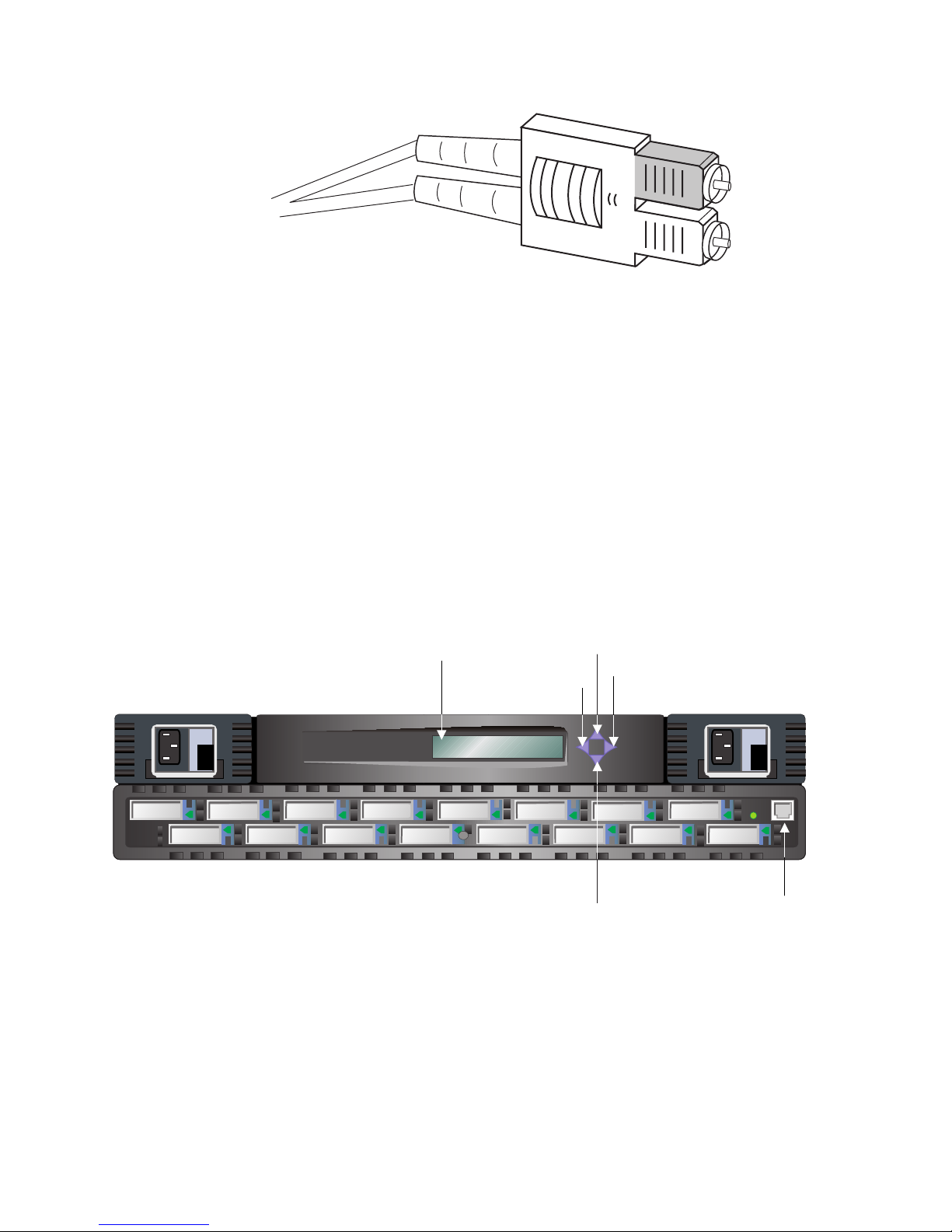
Fiber cables connect to the front panel of the switch using standard dual SC plug
connectors as shown in Figure 5 on page 5.
4 IBM SAN Fibre Channel Switch: 2109 Model S16 Installation and Service Guide
Page 21
Front panel
SJ000044
Figure 5. Dual SC fiber-optic plug connector
The connectors are keyed and must be correctly aligned before they are inserted
into the GBIC-module connector. In most cases, one of the two connector plugs is a
different color to aid in proper connector alignment.
Note: Remove the protective plug from the GBIC. Do not force the fiber-optic plug
into the GBIC module as you may damage the connector, the GBIC module,
or both. Make certain that the fiber surface is clean and free of dust or debris
before inserting the connector into a GBIC module.
Figure 6 shows the front panel buttons.
Figure 6. Front panel functionality
Control buttons
Table 2 on page 6 lists the primary control button functions. The function of the
button changes depending on the menu level. Buttons either control navigating
through the menus or they increment and decrement numeric values.
Display
Fiber Channel Switch 2109 S16
Up button
Tab/Esc button
Down button
Enter button
RJ-45 10 BASE-T
connection
SJ000045
Chapter 1. Introduction 5
Page 22

Table 2. Control buttons
Control
buttons
Down The Down button scrolls down the command list; or, if the user is changing
Up The Up button scrolls up the command list; or, if the user is changing a
Tab/Esc The Tab/Esc button tabs through multiple options. When displaying a menu
Enter The Enter button accepts the input and executes the selected function.
Description
a numeric display, it decrements the numeric value.
numeric display, it increments the numeric value.
item, pressing the Tab/Esc button reverses through previous commands. If
pressed repeatedly, it turns off the front panel display.
When entering a number, the Up and Down buttons start in the slow mode and
change to the fast mode if either button is held down. Most numbers go to a
maximum of 255; for large numbers, it may be faster to use the Down button.
Ethernet connection
Connecting an existing Ethernet 10BASE-T or 100BASE-T LAN to the switch
through the front panel RJ-45 connector gives you access to the internal SNMP
agent of the switch and also allows Telnet and Web access for remote monitoring
and testing. The IP address is changed using the Ethernet port.
Note: The connection is only for Telnet, SNMP agent, and the Web-based server
access. This connection uses no fabric connection.
Front panel LED port indicators
Each switch port has an LED indicator. A properly functioning port with no GBIC
installed has no LED light. A yellow port indicator depicts faults and problems.
The LED color and flash speed of each port, as described in Table 3, indicates the
status of each individual port.
Table 3. Front panel LED status indicators
Front panel LEDs Definition
No light showing No light or signal carrier (no module, no cable) for media interface
LEDs.
Steady yellow Receiving light or signal carrier, but not yet online.
Slow yellow Disabled (as a result of diagnostics or a portDisable command).
Flashes every 2 seconds.
Fast yellow Error, fault with a port. Flashes every one-half second.
Steady green Online (connected with a device over a cable).
Slow green Online, but segmented (loopback cable or incompatible switch).
Flashes every 2 seconds.
Fast green Internal loopback (diagnostic). Flashes every one-half second.
Flickering green Online and frames flowing through port.
When a GBIC is installed and a cable is connected to a properly functioning
fibre-channel device, the LED indicator is a steady green. If a slow green flash is
observed, it indicates that the port is seeing light, but cannot make a proper fabric
connection. This could indicate that a loop back cable is installed, the fabric is
6 IBM SAN Fibre Channel Switch: 2109 Model S16 Installation and Service Guide
Page 23

segmented (an E-port connection to another switch cannot be completed and the
switches cannot form a fabric), or the 2109 Model S16 Switch has been connected
to an incompatible switch.
When frame traffic is being transferred on a port, the LED flickers fast green,
showing that the port is active and is transferring data.
Switch power on and ready indicator
After the power-on self-test (POST) diagnostics have completed, this LED indicates
a successful completion of the system board diagnostics.
Diagnostics overview
The switch is designed for maintenance-free operation. When there is a suspected
failure, the switch has self-diagnostic capabilities to aid in isolating any equipment
or fabric failures.
The switch supports POSTs and diagnostic tests. The diagnostic tests determine
the status of the switch and isolate problems. The diagnostic tests are run using
Telnet commands. For more information about diagnostic testing commands and
procedures, see “Appendix B. Diagnostics” on page 91.
Verifying a power-on self-test (POST)
Table 4 lists the diagnostic tests that are automatically run during a POST.
Table 4. Offline and Online tests
Test Description
CAM test Checks the CAM
Central memory test Checks the system-board SRAMs
CMI conn test Checks the CMI bus between ASICs
Memory test Checks CPU RAM memory
Port loopback test Checks all of the switch hardware. Frames are transmitted,
Port register test Checks the ASIC registers and SRAMs
After the switch completes the POST, the GBIC module returns to a steady state
from the flashing states shown during the tests.
A yellow GBIC module light indicates that the module failed one of the POSTs.
Telnet can display error conditions after the switch completes the POST.
The ready LED verifies a successful POST approximately 2 minutes after power is
turned on.
Running diagnostics
For detailed information about running diagnostics, see “Appendix B. Diagnostics”
on page 91.
looped back and received.
The following diagnostic tests can be run from the Telnet connection of the switch:
v CAM test (camTest)
v Central memory test (centralMemoryTest)
Chapter 1. Introduction 7
Page 24

v CMem data retention test (cmemRetentionTest)
v CMI conn test (cmiTest)
v Cross port test (crossPortTest)
v Memory test (ramTest)
v Port loopback test (portLoopbackTest)
v Port register test (portRegTest)
v Spin silk test (spinSilk)
v SRAM data retention test (sramRetentionTest)
v Switch offline (switchDisable)
v Switch online (switchEnable)
Table 5 shows the available offline and online tests.
Attention: Offline tests are disruptive to switch operations. Do not run these tests
unless you are sure that switch operation can be disrupted.
Table 5. Offline and online test
Offline tests Offline and online tests
camTest crossPortTest
centralMemoryTest ramTest
cmemRetentionTest
cmiTest
portLoopbackTest
portRegTest
spinSilk
sramRetentionTest
Loop (FL) connections
The system-board module is structured to accommodate a single channel FL_port
interface module in the same slot used by the dual G_port interface module. Mixing
|
8 IBM SAN Fibre Channel Switch: 2109 Model S16 Installation and Service Guide
of FL_port and G_port interface modules in different slots is permitted.
Page 25

|
Chapter 2. Customer planning
|
|
|
|
|
|
|
|
|
|
||
||
|
|
|
|
|
|
|
|
||
||
||
||
||
||
||
||
||
||
||
||
||
The following information will be needed to properly configure the 2109 in an
operational environment.
Table 6 shows an example of a completed worksheet for an installed switch.
Following Table 6 is an explanation of each item in Table 6. Table 7 on page 11 is a
blank worksheet for your use. Make as many copies of Table 7 on page 11 as you
need to plan the installation of each of your switches. Provide the system
administrator with copies of the completed worksheets
Table 6. Example of a planning worksheet for a 2109 switch
Item Description
Firmware level V 2.1.7
Firmware location:
Server name
Username
Directory
Switch name 2109-1
Domain ID 1
FCnetID (Fibre-channel IP address)
FC netmask
WWN To be supplied when box is turned on
Role Principal switch
Syslog daemon IP address 192.20.236.4
Users defined - access level admin - admin, petuser - none
SNMP information:
System description TestSANlet1_2109-1
System contacts (Contact name)
System location B/003-3 Col C-4
Event trap level0-5 5
C02STOR01
sanman
G:\sanman\2109\firmware\v2.1
|
|
|
||
||
||
||
||
Enable authentication traps No
RW community string dingo
RO community string pet
Trap recipients IP Address 192.20.236.3
License keys Required for optional features.
|
|
|
The following is a description of the items in Table 6.
Firmware levels
|
|
© Copyright IBM Corp. 1999, 2000 9
Refer to the
2109 Model S16 User’s guide
information.
IBM SAN Fibre Channel Switch
for additional
The firmware levels for the 2109 and the required code that the service
representative is to install on an NT StorWatch Specialist workstation.
Page 26

|
|
Server name
The network name of the server where the StorWatch Specialist is run.
|
|
|
|
|
|
|
|
|
|
|
|
|
|
|
|
|
|
||
||
|
Username
The username on the StorWatch Specialist server that owns the firmware
for the 2109. IBM recommends that this not be a username with
administrative or security privileges on the server.
Directory
The location where the firmware files are located.
Firmware location
The directory location on the StorWatch Server that has the firmware for the
2109. IBM recommends that a different directory be used for each level of
firmware that is loaded.
Switch name
The name of this particular fibre channel switch.
Domain ID
The domain ID that identifies this switch in the SAN configuration.
FCnetID
The fibre channel IP address for this switch.
FC netmask
The netmask for the fibre channel IP network.
WWN The World-wide name assigned by the manufacturer.
Role The role this switch will be assigned (principal switch, subordinate switch, or
disabled switch).
|
|
|
|
|
|
|
|
|
Syslog daemon IP address
The IP address of the host that the syslog daemon messages will be
forwarded to.
Users defined - access level
A list of users in SAN administration network and their roles.
License keys
The required license keys for optional features.
Use Table 7 on page 11 to plan your switch installation. Make a copy of Table 7 on
page 11 for each switch you plan to install.
10 IBM SAN Fibre Channel Switch: 2109 Model S16 Installation and Service Guide
Page 27

|
|
||
||
|
|
Table 7. Blank of a planning worksheet for a 2109 switch
Item Description
Firmware level
Firmware location:
|
|
|
||
||
||
||
||
||
||
||
||
||
||
||
||
|
||
||
||
||
||
Server name
Username
Directory
Switch name
Domain ID
FCnetID (fibre-channel IP address)
FC netmask
WWN
Role
Syslog daemon IP address
Users defined - access level
SNMP information:
System description
System contacts
System location
Event trap level0-5 See
Enable authentication traps
RW community string
RO community string
Trap recipients IP address
License keys
IBM SAN Fibre Channel Switch 2109
Model S16 User’s Guide
|
Chapter 2. Customer planning 11
Page 28

|
|
|
|
Table 8 shows an example of a completed worksheet for port configuration. Table 9
on page 13 is a blank worksheet for your use in planning your port configuration.
Make as many copies of Table 9 on page 13 as you need to plan the installation of
each of your ports.
|
|
||||||||||
|
||||||||
||||||||
||||||||
||||||||
||||||||
|||||||
|||||||
|||||||
|||||||
|||||||
|||||||
|||||||
|||||||
Table 8. Example of a configuration worksheet for a 2109 switch
Port
number
0 2108-1 PMC1-1 2m (6 ft) SW Connects to
1 2108-1 PMC2-2 2m (6 ft) SW Connects to
2 2108-1 PMC3-3 2m (6 ft) SW Connects to
3 2108-2 PMC1-1 2m (6 ft) SW Connects to
4 2108-2 PMC2-2 2m (6 ft) SW Connects to
5 2108-2 PMC3-3 2m (6 ft) SW 205
6 s1411201e0 P2-I3 25m (82 ft) SW 206
7 s1411203e0 P2-I3 25m (82 ft) SW 207
8 s1411205e0 P2-I2 25m (82 ft) SW 208
9 2109-15 Port 8 2m (6 ft) SW 209
10 2109-15 Port 13 2m (6 ft) SW 213
11 Open SW
12 K38 node 1 25m (82 ft) SW 214
Device
name
Device port Cable
length
Port type Notes Cable
number
200
2105-1
201
2105-1
202
2105-1
203
2105-1
204
2105-1
|
12 IBM SAN Fibre Channel Switch: 2109 Model S16 Installation and Service Guide
Page 29

|
|
|||||||||||
|
|||||||
|||||||
|||||||
|||||||
|||||||
|||||||
|||||||
|||||||
|||||||
|||||||
|||||||
|||||||
|||||||
|||||||
|||||||
|||||||
Table 9. Blank of a port configuration worksheet for a 2109 switch
Port
number
0
1
2
3
4
5
6
7
8
9
10
11
12
13
14
15
Device
name
Device port Cable
length
Port
type
Notes Cable
number
|
Chapter 2. Customer planning 13
Page 30

|
|
|
|
Table 10 shows an example of a completed worksheet for an installed switch.
Table 11 on page 15 is a blank worksheet for your use in planning your switch
installation. Make as many copies of Table 11 on page 15 as you need to plan the
installation of each of your switches.
|
|
||||||
||||
||||
||||
||||
||||
||||
Table 10. Example of a zone definitions worksheet
Zone member type
(switch, port, WWN)
Port (ID,P) 1, 15 Test_Zone_Config_1 K38 node 1
Port (ID,P) 1, 0 Same 2108-1 PMC1-1
Port (ID,P) 15, 3 Same 2108-2 PMC1-4
Port (ID,P) 15, 14 Same K38 node 2
Port (ID,P) 1, 10 Same EMC-1 dir 5 port 0
Port (ID,P) 15, 10 Same EMC–1 dir 5 port 0
Zone member Zone configuration
name
Comments
|
14 IBM SAN Fibre Channel Switch: 2109 Model S16 Installation and Service Guide
Page 31

|
|
||||||
||||
||||
||||
||||
||||
||||
Table 11. Blank of a zone definitions worksheet
Zone member type
(switch, port, WWN)
Port (ID,P)
Port (ID,P)
Port (ID,P)
Port (ID,P)
Port (ID,P)
Port (ID,P)
Zone member Zone configuration
name
Comments
|
Chapter 2. Customer planning 15
Page 32

|
|
|
|
Table 12 shows an example of a completed worksheet for an installed switch.
Table 13 on page 17 is a blank worksheet for your use in planning your switch
installation. Make as many copies of Table 13 on page 17 as you need to plan the
installation of each of your switches.
|
|
|||||||
||||
||||
||||
||||
||||
||||
||||
||||
||||
||||
||||
||||
||||
||||
||||
||||
||||
||||
||||
||||
||||
||||
||||
Table 12. Zone configuration worksheet example
Zone member type
(switch, port, WWN)
Port (ID, P) 1, 1 Test_Zone_Config_1 2108-1 PMC2–2
Port (ID, P) 1, 2 Same 2108-1 PMC3–3
Port (ID, P) 1, 3 Same 2108-1 PMC1–1
Port (ID, P) 1, 4 Same 2108-2 PMC2–2
Port (ID, P) 1, 5 Same 2108-2 PMC3–3
Port (ID, P) 1, 6 Same s1411201e0 P2–I3
Port (ID, P) 1, 7 Same s1411203e0 P2–I3
Port (ID, P) 1, 8 Same s1411205e0 P2–I3
Port (ID, P) 1, 9 Same 2108-15 port 8
Port (ID, P) 1, 11 Same EMC-1 dir 16 port 0
Port (ID, P) 1, 12 Same 2102-3 BDI
Port (ID, P) 1, 13 Same 2109-15 port 13
Port (ID, P) 15, 1 Same 2108-1 PMC2-5
Port (ID, P) 15, 2 Same 2108-1 PMC3-6
Port (ID, P) 15, 0 Same 2108-1 PMC1-4
Port (ID, P) 15, 4 Same 2108-2 PMC2-5
Port (ID, P) 15, 5 Same 2108-2 PMC3-6
Port (ID, P) 15, 6 Same s1411201e0 P3-I3
Port (ID, P) 15, 7 Same s1411203e0 P3-I3
Port (ID, P) 15, 8 Same 2109-1 port 9
Port (ID, P) 15, 9 Same s1411206e0 P2–I2
Port (ID, P) 15, 11 Same EMC-1 dir 16 port 2
Port (ID, P) 15, 13 Same 2109-1 port 13
Zone
member
Zone configuration
name
Connects to
|
16 IBM SAN Fibre Channel Switch: 2109 Model S16 Installation and Service Guide
Page 33

|
|
|||||||
||||
||||
||||
||||
||||
||||
||||
||||
||||
||||
||||
||||
||||
||||
||||
||||
||||
||||
||||
||||
||||
||||
||||
Table 13. Blank of a zone configuration worksheet
Zone member type
(switch, port, WWN)
Port (ID, P)
Port (ID, P)
Port (ID, P)
Port (ID, P)
Port (ID, P)
Port (ID, P)
Port (ID, P)
Port (ID, P)
Port (ID, P)
Port (ID, P)
Port (ID, P)
Port (ID, P)
Port (ID, P)
Port (ID, P)
Port (ID, P)
Port (ID, P)
Port (ID, P)
Port (ID, P)
Port (ID, P)
Port (ID, P)
Port (ID, P)
Port (ID, P)
Port (ID, P)
Zone
member
Zone configuration
name
Connects to
|
Chapter 2. Customer planning 17
Page 34

18 IBM SAN Fibre Channel Switch: 2109 Model S16 Installation and Service Guide
Page 35

|
Chapter 3. Installing the switch
This chapter discusses the installation of the SAN Fibre Channel 2109 Model S16
Switch.
Pre-installation checklist
Verify the items in the pre-installation checklist, shown in Table 14 before you begin
the installation of the 2109 Model S16 Switch. This ensures a successful installation
of the product. Some of the steps may vary depending on which host platform you
attach to the switch. The customer should have the internet protocol (IP) adapter for
the switch and should have arranged for other installation activities.
Table 14. Pre-installation checklist
Step Customer action or decision Comments and references
1
|
|
2 Ensure that the required host platform
v Desktop install
v Rack-mount install
v Location
OS service pack is installed. For
example: Microsoft
service pack 5 (or later) and any
required hot fixes.
®
Windows NT 4.0,
Determine whether the 2109 Model S16
Switch is to be installed on a desktop or if
it is to be rack mounted.
For a current list of supported platforms,
required host platform code updates, and
information about how to obtain them, see
our Web site at:
www.ibm.com/storage/fcswitch
3 Ensure that the required fibre-channel
host bus adapter (HBA) BIOS, and
device driver are available.
4 Ensure that all host fiber-channel
cables have been ordered with the
product or have been pre-installed and
checked
Ensure that all cables have been
marked with:
v Host system identifier
v Switch identifier
5 Ensure that the disk or tape system
installation has been completed.
For tape attachment, ensure that the
tape device driver was installed or
updated.
or contact IBM technical support.
For a list of supported HBAs and the
required basic input/output system (BIOS)
and device driver, see our Web site at:
www.ibm.com/storage/fcswitch
or contact IBM technical support.
Refer to the HBA specification provided
with your HBA.
Usually performed by a service
representative during target device
installation.
© Copyright IBM Corp. 1999, 2000 19
Page 36

Table 14. Pre-installation checklist (continued)
Step Customer action or decision Comments and references
6 Decide on the switch network
parameters.
Obtain the switch network parameters
from your network administrator.
|
|
|
|
|
|
|
Installing the switch
The 2109 Model S16 Switch is installed either in a rack-mount configuration or a
tabletop configuration.
Ethernet port configuration decisions:
v Static IP address _____________
v Netmask (if required)__________
If the switch, the SNMP manager, or
the Syslog server are on different
TCP/IP subnets (see note), assign the
default network gateway address and
route table entries.
Attention: Save this configuration
for future reference.
7 Install the Ethernet cable from the
server (see note) to the network hub.
8 Install the Ethernet cable from the
network hub where the switch will be
installed.
Note: The term server used here refers to the computer used for the IBM StorWatch
Specialist.
Attention: Use of incorrect network
parameters can cause problems on the
Ethernet network.
None
None
Note: Before installing GBICs, power cords, and the optional second power supply,
install either the rubber tabletop mounting feet or install the switch in the
rack.
Tabletop installation
The switch is shipped in its tabletop configuration. Adhesive rubber feet are
supplied. These must be applied to the bottom of the switch in the four depressions
provided.
1. Turn the switch upside down and lay it on its top.
2. Clean the four depressions by wiping them free of dust.
3. Remove the rubber feet from the sheet that is provided with the shipping kit,
and place one rubber foot in each depression.
4. Firmly press the rubber feet in place.
5. Return the switch to its normal upright position, and place it in its intended
service location.
6. Go to “Installing the optional power supply” on page 24 (even if you do not have
an optional power supply).
Rack-mount installation
Read the following statements before starting the rack-mount installation:
20 IBM SAN Fibre Channel Switch: 2109 Model S16 Installation and Service Guide
Page 37

Attention: Do not install this switch in a rack where the internal rack-ambient
temperature will exceed 40°C.
v Do not install this unit in a rack where the airflow is compromised. The airflow is
from the back of the unit to the front; therefore, do not block the front or the back
of the rack.
v Take care that a hazardous condition is not created due to uneven mechanical
loading when installing this unit in a rack. If the rack this equipment is being
installed in has a stabilizer, it must be firmly attached before installing or
removing this unit.
|
|
|
v This unit requires 2 A of power with an input of 110 - 127 V ac or 1 A with an
input of 200 - 240 V ac. Ensure that you do not overload the circuits you are
connecting this equipment to.
DANGER
An electrical outlet that is not correctly wired could place a hazardous
voltage on the metal parts of the system or the products that attach to the
system. It is the customer’s responsibility to ensure that the outlet is
correctly wired and grounded to prevent an electrical shock (72XXD201).
Before starting the switch rack-mount installation process, locate the rack-mount
slides and the mounting bracket package provided in the shipping container.
Overview
The rack-mount installation process is performed in four steps:
1. Mounting the moving slide and locking the ears to the switch.
2. Mounting the fixed portion of the slide in the rack.
3. Inserting the switch and moving a portion of the slide into the fixed portion on
the rack.
4. Locking the switch in the rack using the mounting ears installed in step 1.
Follow the detailed instructions for each step as identified in the following sections.
Chapter 3. Installing the switch 21
Page 38

Step 1. Mounting the moving slide and locking ears to the switch
1. Locate and disassemble the slides by fully extending the slide, pressing the
release as shown in Figure 7, and pulling the slide apart.
SJ000046
Figure 7. Moving slide
2. Mount the moving portion of the slide and the locking ears to the switch as
shown in Figure 8. Use the screws provided with the locking ears. Mount the
slide portion first, and then the locking ears.
Figure 8. Mounting the moving portion of slide and locking ears to the switch
Step 2. Mounting the fixed portion of the slide in the rack
1. Open the rack-mounting brackets kit and mount the brackets to the wider fixed
portion of the four slides. One bracket mounts to each end of the fixed portion
of the slides as shown in Figure 9 on page 23.
22 IBM SAN Fibre Channel Switch: 2109 Model S16 Installation and Service Guide
Front
SJ000047
Page 39

Leave the mounting screws on the rear bracket finger tight. You will tighten
these after the switch is installed. The brackets on the front should be tightened,
leaving approximately 15 mm (5/8 in.) of the bracket in front of the end of the
outer fixed slide member. This is to allow installation space for the locking ears.
SJ000048
Figure 9. Mounting the fixed portion of the rail and the locking ears to the rack
2. Using the rack-mount clips and the screws provided, mount the fixed portion of
the slides with the mounting brackets to the vertical mounting bars in the rack.
3. Install three rack clips at the front and at the back of the rack. The middle rack
clip in the front is for the locking ears.
Step 3. Inserting the switch and the moving portion of the slide
into the fixed portion on the rack
1. Lift the switch and match the portion of the rail mounted on the switch with the
receiving rail members mounted in the rack, as shown in Figure 10 on page 24.
Push the switch all the way back until it is fully in the rack.
Chapter 3. Installing the switch 23
Page 40

Figure 10. Inserting slides into the rack rails
2. Slide the switch back and forth on the rack several times to ensure that it
moves freely. Move the switch partially forward and tighten the mounting screws
on the rear brackets that were left finger tight.
Step 4. Locking the switch in the rack using the mounting ears
installed in step 1
1. Slide the switch fully back in the rack.
2. Using the remaining screws provided with the locking ears, lock the switch in
the rack.
This completes the rack mounting of the switch.
To install GBICs, see “Installing GBICs” on page 25. To install the optional power
supply, see “Installing the optional power supply”.
Installing the optional power supply
Before installing the optional power supply, read the following danger notices.
DANGER
To prevent a possible electrical shock during an electrical storm, do not
connect or disconnect cables or station protectors for communications
lines, display stations, printers, or telephones. (72XXD003)
SJ000049
DANGER
Do not attempt to open the covers of the power supply. Power supplies are
not serviceable and are replaced as a unit. (72XXD300)
DANGER
An electrical outlet that is not correctly wired could place hazardous
voltage on metal parts of the system or the products that attach to the
system. It is the customer’s responsibility to ensure that the outlet is
correctly wired and grounded to prevent an electrical shock. (72XXD201)
24 IBM SAN Fibre Channel Switch: 2109 Model S16 Installation and Service Guide
Page 41

DANGER
To prevent a possible electrical shock when installing the device, ensure
that the power cord for that device is unplugged before installing signal
cables. (72XXD204)
If you do not have the optional second power supply, locate the power cord for the
single power supply that is already installed in the machine frame. Insert the power
cord into the power receptacle on the front of the machine. Go to “Installing GBICs”.
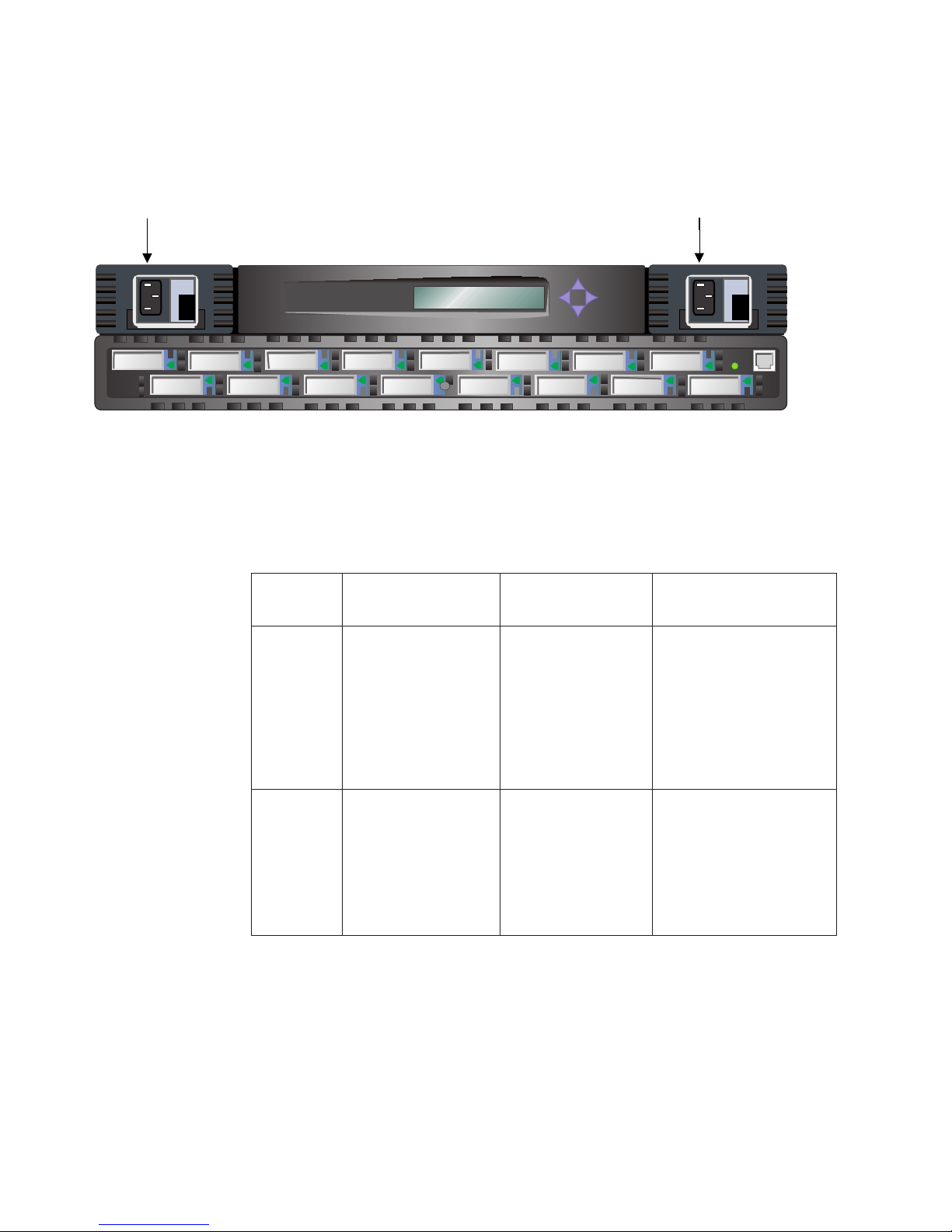
If you do have an optional second power supply, remove it from its shipping
container.
Look at Figure 11. On your machine, the left power supply location is filled with a
temporary cover. Grasp the cover and pull it forward while holding the machine
firmly. Remove and discard the cover.
Power supply 1Power supply 2
Fiber Channel Switch 2109 S16
Figure 11. 2109 model S16 with two power supplies
To install the optional second power supply, perform the following steps:
1. Look at the back of the power supply; the power supply is installed with the
connector in the down position.
2. Pull out the handle on the front of the power supply by grasping the handle at
the top and pulling out and down.
3. Slide the second power supply unit into its slot until it connects into the back
panel.
4. Lock the handle into the power supply by pushing the handle back into the
upright and locked position.
5. Locate the power cords and insert them into the power receptacles on the front
of the machine. Go to “Installing GBICs”.
Installing GBICs
The 2109 Model S16 Switch comes standard with four GBICs as shown in
Figure 12 on page 26. Up to 12 additional GBICs are available. GBICs can be
inserted in any port in the switch in any order, including skipping ports.
SJ000050
Chapter 3. Installing the switch 25
Page 42

Dust protection
rubber plug
SJ000051
Figure 12. GBIC
Figure 13 shows the front of the GBIC. The dust protection rubber plug must remain
in the GBIC until a fibre-channel cable is inserted. The other end of the GBIC is
inserted in the switch.
The GBICs are keyed and only seat if inserted correctly. The GBICs in the top row
of ports are inserted with the swing handle down as shown in Figure 13. The GBICs
in the bottom row of ports are rotated 180° so that the swing handle is on top.
Swing handle
Figure 13. GBIC swing handle
Setting the IP address
The switch ships from the factory with the default IP address (10.77.77.77)
pre-installed on the switch. This IP address is noted on a label on the top front edge
of the switch. This address is for the external Ethernet connection.
Use this default address to attach to the customer’s local area network (LAN) and
to establish a network connection to the switch. You can change this IP address by
using a Telnet command issued from any server having access to the same LAN.
This is the easiest way to set the IP address. Ask the customer’s LAN administrator
if the default address can be used. If this is not possible, set the IP address using
the front panel. See “Setting the IP address from the front panel” on page 28.
Instructions are provided for setting the IP address using either the front panel or
the Ethernet port. The locations of these ports are shown in Figure 14 on page 27.
Set the IP address by using the pre-installation checklist you obtained from the
customer LAN Administrator.
SJ000058
26 IBM SAN Fibre Channel Switch: 2109 Model S16 Installation and Service Guide
Page 43

|
Power supply 2
Fiber Channel Switch 2109 S16
|
|
Figure 14. Ethernet port connector
|
Setting the IP address using the Ethernet port
If you cannot use this method, go to “Setting the IP address from the front panel” on
|
|
|
|
|
|
|
|
|
|
|
|
|
|
|
|
|
|
|
|
|
|
|
|
|
|
page 28.
1. Attach the customer’s LAN to the front panel of the switch by plugging an
existing Ethernet 10BASE-T or 100BASE-T LAN cable to the RJ-45 connector
on the front of the switch.
2. Turn on the switch. If two power supplies are present, turn on both. After
waiting two minutes for the diagnostics to complete, continue with step 3.
3. From a LAN attached server, type: Telnet IP address (for example: Telnet
10.77.77.77). If this is the first installation, the IP address will be as written on
the label on the top left corner of the switch. If the switch was previously
installed and the label has been maintained, the current address should be
used from the label. If the label was not maintained, you must get the address
from the customer.
The switch displays as shown; in each case enter the requested information.
After each entry, press Enter.
4. Login: admin
The switch is shipped with the phrase “admin” set as the default administrator
name.
5. Password: password
The switch is shipped with the word “password” set as the default password.
You do not see the password as you type.
6. Ipaddress:admin>ipAddrSet
The Ipaddress is the command to set the IP address.
7. Ethernet IP address [the current address is shown]: new IP address.
This is the new address from the customer.
8. Ethernet Subnetmask [Enter the current subnet mask or the word “None”]: new
Subnetmask.
Operator panel
Power supply 1
RJ-45 Ethernet
connector
SJ000054
|
Note: Enter the new Subnetmask the customer has provided; or, if none is
|
required, press Enter.
Chapter 3. Installing the switch 27
Page 44
|
|
|
9. Fibre-channel IP Address [If none]: press Enter.
10. Fibre-channel Subnetmask [If none]: press Enter.
11. Gateway address [The current or new Gateway address or “None”]:
|
|
|
|
Note: Enter the Gateway address the customer has provided; or, if none is
required, press Enter.
12. Ipaddress:admin>logout
The logout command ends the Telnet session.
You have completed the installation of the 2109 Model S16 Switch. To do a quick
check of the fibre-channel ports on the switch before returning the machine to the
customer, see “Switch installation verification” on page 31.
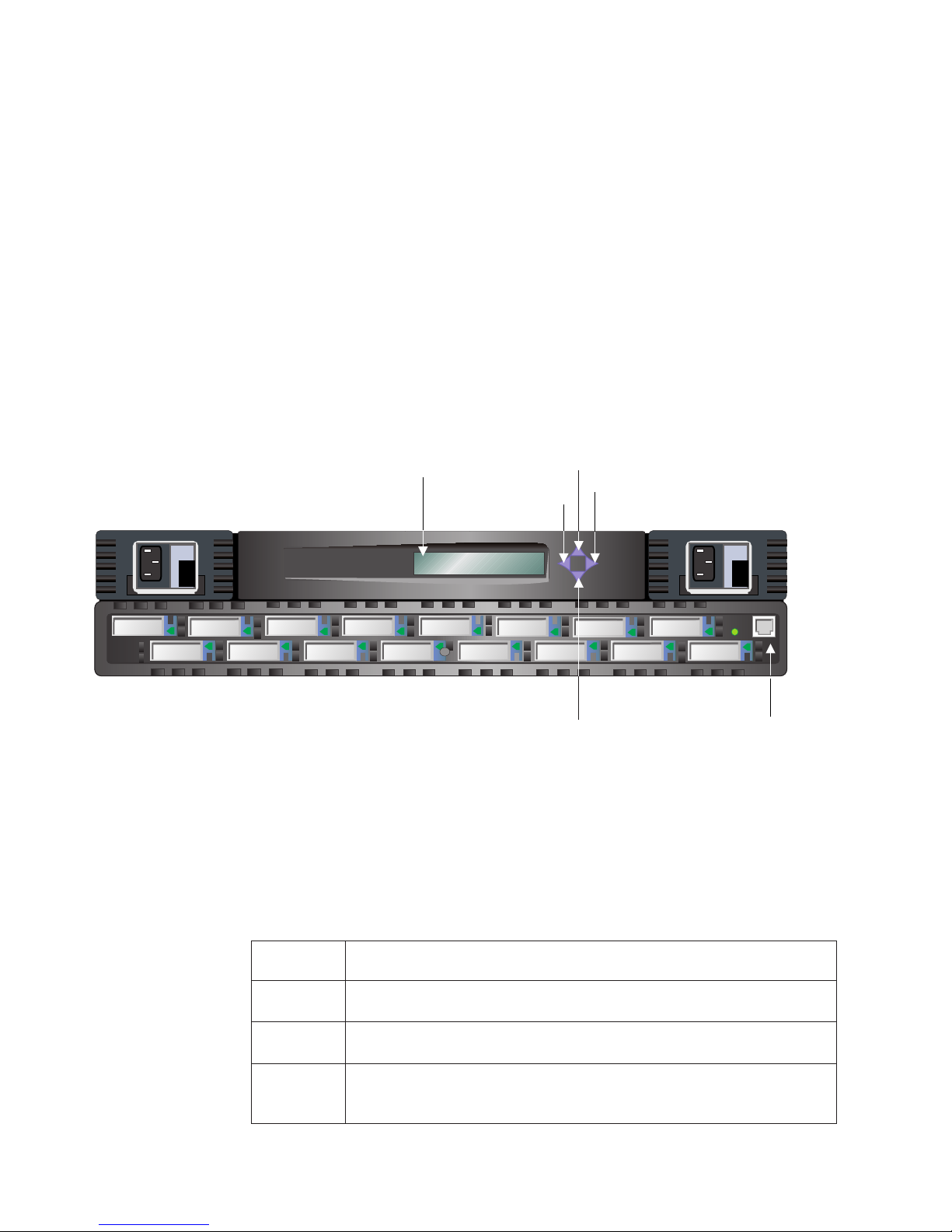
Setting the IP address from the front panel
See Figure 15 for the location and function of each button on the front panel of the
2109 Model S16 Switch.
Display
Tab/Esc button
Fiber Channel Switch 2109 S16
Up button
Enter button
Down button
Figure 15. Front panel - operator display and control buttons
Control buttons
Table 15 lists the primary control button functions. The function of the button
changes depending on the menu level. Buttons either control navigating through the
menus or increment or decrement numeric values.
Table 15. Control buttons
Control
button
Down The Down button scrolls down the command list, or, if the user is changing a
Up The Up button scrolls up the command list, or, if the user is changing a
Tab/Esc The Tab/Esc buttons tab through multiple options. When displaying a menu
28 IBM SAN Fibre Channel Switch: 2109 Model S16 Installation and Service Guide
Description
numeric display, it decrements the displayed value.
numeric display, it increments the displayed value.
item, pressing the Tab/Esc button reverses through previous commands and,
if pressed repeatedly, turns off the front panel display.
RJ-45 10BASE-T
connection
SJ000055
Page 45

Table 15. Control buttons (continued)
Control
button
Enter The Enter button accepts the input and executes the selected function.
Description
When entering a number, the Up and Down buttons start in the slow mode and
change to the fast mode if either button is held down. Most numbers go to a
maximum of 255; for large numbers, it may be faster to use the Down button.
Setting the IP address from the front panel:
1. Turn on the switch.
Wait two minutes while the diagnostics complete. The display panel goes blank
after the diagnostics have completed.
2. Press the Up button. The switch displays:
Configuration menu
3. Press the Enter button. The switch displays:
Ethernet IP address
4. Press the Enter button. The switch displays the current Ethernet IP address in
the form xxx xxx xxx xxx
5. Change the current address to the preferred address.
Notes:
a. Press the Tab/Esc button to move the cursor (the entry point) from one
field to the next. If you go past a field, continue pressing the Tab/Esc
button until the cursor wraps around and returns to the desired spot.
b. Press the Up button to increment the current field. Press the Down button
to decrement the current field. Hold either button down to make these
actions happen rapidly. The numbers in the field wrap from 0 to 255 or
from 255 to 0, depending on whether you are incrementing or
decrementing. This helps you get to the desired value quickly.
When you have all fields set to the desired value continue with the next step:
6. Press the Enter button . The switch displays:
Accept ? Y N
Press the Tab/Esc button to indicate Yes. Press the Enter button to indicate No.
a. If you respond No, the switch again displays the Ethernet IP address. You
can now restart the process.
b. If you respond Yes, the switch displays: updating the Config.
This response causes the new address to be stored.
After the switch has made the change, it again displays the Ethernet
address.
c. If no other address is to be changed (gateway or Subnet), stop here by
pressing the Tab/Esc button. You are done setting up the switch.
d. If you need to set other switch addresses (gateway or subnetmask), press
the Up button. The switch displays: Ethernet Subnetmask.
7. Press the Enter button. The switch displays the current Ethernet Subnetmask in
the form xxx xxx xxx xxx.
8. Change the current Subnetmask to the preferred address.
When you have all fields set to the desired value, continue with the next step.
Chapter 3. Installing the switch 29
Page 46

9. Press the Enter button. The switch displays:
Accept ? Y N
Press the Tab/Esc button to indicate Yes. Press the Enter button to indicate No.
a. If you respond No, the switch again displays: Ethernet Subnetmask, and you
can restart the process.
b. If you respond Yes, the switch displays: Updating the Config.
This response causes the new address to be stored.
After the switch has made the change, it again displays Ethernet
Subnetmask.
c. If no other address is to be changed (gateway or subnet), press the Tab/Esc
button. You are done setting up the switch.
d. If you need to set other switch addresses (gateway or domain), press the
Up button. The switch displays: Fibre Channel IP address (not required at
this time).
10. Press the Up button. The switch displays: Fibre Channel Subnetmask (not
required at this time).
11. Press the Up button. The switch displays: Gateway Address.
12. Press the Enter button. The switch displays the current Gateway address in
the form xxx xxx xxx xxx.
13. Change the current gateway address to the preferred address.
Press the Up button to increment the current field. Press the Down button to
decrement the current field. Hold the button down to make this happen rapidly.
The numbers in the field wrap from 0 to 255 or from 255 to 0, depending on if
you are incrementing or decrementing. This helps you get to the desired value
quickly.
When you have all fields set to the desired value, continue with the next step.
14. Press the Enter button. The switch displays: Accept ? Y N.
Press the Tab/Esc button to indicate Yes. Press the Enter button to indicate No.
a. If you press No, the switch again displays: Gateway Address, and you can
restart the process.
b. If you press Yes, the switch displays: Updating the config.
This causes the new address to be stored.
After the switch has made the change, it again displays: Gateway Address.
c. If no other address is to be changed (gateway or subnet), press the
Tab/Esc button. You have completed setting up the switch.
d. If you need to set other switch addresses such as domain, press the Up
button. The switch displays: Domain.
15. Press the Enter button. The switch responds by displaying the current domain
in the form: xxx xxx xxx xxx.
16. Change the current domain to the preferred address.
When you have all fields set to the desired value continue with the next step.
17. Press the Enter button. The switch displays: Accept ? Y N.
Press the Tab/Esc button to indicate Yes. Press the Enter button to indicate No.
a. If you press No, the switch displays: Domain, and you can restart the
process.
b. If you press Yes, the switch displays: Updating config.
This causes the new address to be stored.
After the switch has made the change, it again displays: Domain.
30 IBM SAN Fibre Channel Switch: 2109 Model S16 Installation and Service Guide
Page 47

18. Press the Tab/Esc button.
You have completed the installation of the 2109 Model S16 Switch. To do a
quick check of the fibre-channel ports on the switch before returning the
machine to the customer, see “Switch installation verification”.
Switch installation verification
Perform this procedure to verify that all GBICs are installed and working correctly.
1. Turn off the switch.
2. Turn on the switch (if this is a dual power switch, turn on both power supplies).
3. Verify that the associated power supply LEDs are on.
4. Wait two minutes while the POST diagnostics run.
5. Verify that the switch-ready LED is on.
6. Plug the appropriate wrap connector (black for shortwave and grey for
longwave) into each GBIC. Verify that each associated port LED shows a slow
green that flashes every two seconds.
7. If any of the previous checks fail, see “Chapter 4. Maintenance action plans” on
page 33. If not, return the machine to the customer.
Code upgrade procedure
The 2109 Model S16 Switch is shipped with the latest level of code. When new
code is released, it can be easily downloaded to the switch. This task requires
saving the data and executable software to the customer’s server.
The latest code can be obtained from the SAN Fibre Channel Switch Web site at:
www.ibm.com/storage/fcswitch
This Web site provides instructions for downloading the code and loading it on the
switch. Loading new code to the switch can be done without disrupting the switch.
To make the new code functional, the switch must be turned off and then turned on.
Upgrade procedure
You can download firmware to the switch from either a UNIX host or a Windows NT
host. For a UNIX host, no special software is needed. For a Windows NT host, you
need a daemon to support a remote shell (RSH) with the firmware on the Web site.
This daemon is available from the Web site. Firmware download is by way of a
remote procedure call (RPC) command running on top of transmission control
protocol (TCP) between the switch and the host.
Downloading firmware from a UNIX®host
Perform this procedure to download new firmware.
1. Download the firmware from the Web site at:
www.ibm.com/storage/fcswitch
Remember the directory name where you save the code.
Code can only be loaded to the switch over the Ethernet LAN port.
2. Start a Telnet session to the switch from a LAN-attached server that has
connectivity to the switch.
The command format is:
Chapter 3. Installing the switch 31
Page 48

telnet [switch IP address]
3. Login using the admin userid. For example:
login: admin
4. Enter the password at the prompt. For example:
Password: password
Respond to the password prompt with the current switch password. The switch
ships with a default password of “password”.
5. Type the following command:
firmwareDownload [“host name/IP address”], [“user name”], [“filename”]
For example: firmwareDownload “192.111.2.1”, “timm”,
“/tmp/os/v2.0.1a_0621”
Note: The host name is the host name or the host IP address. The username
is a valid host username. The file name is a path to the new firmware
file.
The RSH server validates the username and delivers the file to the switch
where it is stored in flash memory.
6. Restart the switch to initiate the new firmware.
Downloading firmware using a Microsoft®Windows NT operating
system
Perform this procedure to download firmware using Windows NT.
1. Download the firmware from the Web site at:
www.ibm.com/storage/fcswitch
Remember the directory name where you save the code.
Download the two utilities (rshd.exe and cat.exe) from the Web site. Download
these into the same directory as the firmware.
2. In a DOS window, enter:
rshd [to execute the RSH daemon].
®
3. Go to “Downloading firmware from a UNIX
2 through 6.
Note: When downloading to a switch with the firmwareDownload command, you
must use UNIX directory (forward slash /) addressing for the directory
location in the command, not PC (backward slash \) directory addressing.
For example, from Windows NT the firmwareDownload command would be:
firmwareDownload “192.111.2.1”, “timm”, “/tmp/os/v2.0.1a_0621” .
host” on page 31 and perform steps
32 IBM SAN Fibre Channel Switch: 2109 Model S16 Installation and Service Guide
Page 49

Chapter 4. Maintenance action plans
This chapter discusses the maintenance action plans (MAPs) for the 2109 Model
S16 Switch.
All service actions start from this point. The instructions in this chapter resolve most
switch or GBIC failures.
The switch provides extensive diagnostics that can be used in extended service
environments that are not resolved in these maps. These diagnostics are described
in the overview in “Chapter 1. Introduction” on page 1 and extensively in
“Appendix B. Diagnostics” on page 91. Before beginning, familiarize yourself with
Figure 16 to understand where the various switch components and indicators are
located.
Power supply 2
Port 0
Figure 16. Front panel of the 2109 Model S16 Switch
Port LEDs
Attention: If you are going to service a functional switch, never unplug cables or
GBICs when there is activity on the associated ports. This causes an immediate
failure of the communications path. To determine if a port has active
communications, see “Visually inspect the LEDs” on page 34. If it becomes
necessary to unplug active ports, you must have the customer stop all
communications on these ports.
Power supply 1
Fiber Channel Switch 2109 S16
Port 15
Ready LED
Ethernet port
SJ000056
Problem determination start map
Always start any problem determination here and review the following steps. Gather
as much information as possible before performing a repair action.
For the latest information on the SAN Fibre Channel Switch, go to our Web site at:
www.ibm.com/storage/fcswitch
System reported error
The customer has reported a switch-related system error message, or the customer
has reported a failure when accessing storage or hosts that are attached to the
© Copyright IBM Corp. 1999, 2000 33
Page 50

switch. If the host-reported error message from the switch is known, or a customer
communications failure symptom is known, go to Table 16 on page 35. With the
error message or the symptom identified, perform the recommended action as
defined in Table 17 on page 35.
Visually inspect the LEDs
Observe the front panel LED status indicators and check them against the
information in Table 16 on page 35. If a faulty behavior exists, perform the
recommended action as defined in Table 17 on page 35.
Determine if zoning is in effect
The 2109 Model S16 Switch implements zoning.
switch to not allow some ports to communicate to others. It is possible that the
customer has ports zoned in a way that prevents them from communicating. Ask
the customer if zoning is in effect. If it is, the customer should check the zoning
setup to make sure that zoning is not the source of the problem.
Zoning
is a way of telling the
|
|
|
|
Zoning is explained in the
Guide
. To display and check zones, the customer must log on to the switch using
Telnet in admin mode and issue the zoneShow command. If any zones are active
or configured, they are displayed.
IBM SAN Fibre Channel Switch 2109 Model S16 Users
Checking problems on attached devices
To determine whether the attached devices are the source of the problem, check
the following on the attached devices:
v LEDs
v Display panels
v Firmware levels
v Operability
Checking FC host versions
Determine the current versions of the following hardware and software elements:
v The operating system version
v The service pack version
v The hot fix version
v The HBA hardware version
v The HBA firmware version
v The HBA device driver version
Compare the current versions with the list of supported host platforms and
fibre-channel host bus adapters on the following Web site:
|
|
www.ibm.com/storage/fcswitch
If an update is required for any of these elements, perform the update.
34 IBM SAN Fibre Channel Switch: 2109 Model S16 Installation and Service Guide
Page 51

Service reference table
Table 16 shows a description of the error messages and the recommended actions.
Table 16. Service reference table
Error
message
Fan failure The customer has reported that a fan failure was reported to the
Power
supply
failure
Description Action
See
Table 17.
System reported error message
1
system.
The customer has reported that a power supply failure was reported
to the system.
The customer has reported a failure to communicate with a host
or device
There is a communication failure on all ports. 3
There is a communication failure on some ports. 4
Visual LED observation
Slow yellow blink port LED (2 second blink). 5
Fast yellow blink port LED (one-half second blink). 5
Steady yellow port LED. 5
Slow green blink port LED (2 second interval). 5
Fast green blink port LED (one-half second interval). 5
Steady green port LED (port is online and the connected host or
device is not sending data).
Flickering green port LED (port is online and the connected host or
device is sending data).
Port LED is off (and a GBIC and cable are installed). 5
Port LED is off (no GBIC is installed). 0
Port LED is off (GBIC is installed but no cable). 5
Switch ready LED is in any state other than steady green. 6
Power supply LED is in any state other than steady green. 7
2
0
0
Action codes and recommended actions
Table 17 shows the action codes and the recommended action for each action
code.
Table 17. Action code and recommended actions
Action
code
0 Normal, no action required.
1 See “Fan failure action (action 1)” on page 36.
2 See “Power supply failure action (action 2)” on page 36.
3 See “All ports fail to communicate action (action 3)” on page 37.
Recommended action
Chapter 4. Maintenance action plans 35
Page 52

Table 17. Action code and recommended actions (continued)
Action
code
4 See “Some ports fail to communicate action (action 4)” on page 38.
5 See “Abnormal port LED action (action 5)” on page 39.
6 See “Abnormal ready LED action (action 6)” on page 41.
7 See “Abnormal power supply LED action (action 7)” on page 41.
Recommended action
Fan failure action (action 1)
You are here as a result of a switch message to the system indicating that a fan
failure has occurred, or you suspect a fan failure for some other reason.
When a single fan fails, the switch continues to function indefinitely unless a second
fan fails, or a very severe cooling environment exists (high ambient temperature). If
a second fan fails or the environment is such that the remaining fans cannot
maintain a safe operating temperature, the switch shuts down before any damage is
done. Replacing the fan returns the switch to normal service. If the switch has shut
down, continue with the following procedure. However, if a severe cooling
environment exists, have the customer resolve the situation.
1. If the failure is a single fan, the switch continues to function, and no damage to
the switch occurs. You can verify that one of the fans has failed on a Model S16
or Model S08 by checking if a fan is not turning at the back of the switch. If the
switch has shut down, you need to start up the switch to perform this check.
2. If a fan has failed, replace the fan. See “Replacing a fan assembly” on page 48.
The switch can remain operational during this process. If the switch is an 8-port
switch and is rack mounted, you may need to slide the switch forward on its
rack mounts to access the fans.
3. After replacing the fan (and turning the switch back on if a shutdown had
occurred), verify that all fans are turning. If all fans are turning, return the
machine to the customer.
Power supply failure action (action 2)
This service action is the result of a switch message to the system indicating that a
power supply failure has occurred on a dual-power machine. The message to the
system can only occur on a dual-power machine. This is because the other power
supply keeps the machine operational allowing the message to be sent.
1. Observe the front of the switch. The power supplies are located on the left and
on the right side of the switch. One of these power supplies should have the
green LED on, and the other should have the green LED off.
For the power supply with the green LED off, verify that the power cord is
seated correctly, that the power switch is in the on position, and that there is
power present in the power outlet.
2. If the green LED is now on, turn the power switch off. Wait 15 seconds and turn
the power switch on again. If the green power supply LED is again on, return
the machine to the customer.
3. If the green LED is still off, replace the power supply. See “Replacing the power
supply” on page 45. A dual-power machine can remain operational during this
process.
4. After replacing the power supply, turn the power switch on and verify that the
green power supply LED is on. If the green power supply LED is on, return the
machine to the customer.
36 IBM SAN Fibre Channel Switch: 2109 Model S16 Installation and Service Guide
Page 53

5. If the green power supply LED is not on, recheck the power cord seating, the
power switch, and the wall outlet. If these are all correct, replace the chassis.
See “Replacing the chassis with touchpad” on page 50. Replacing the chassis is
a disruptive process. All switch service is lost during the replacement process. A
dual power machine can continue to function on one power supply. Before
replacing the chassis, schedule this replacement at a time when it is convenient
to the customer.
All ports fail to communicate action (action 3)
This service action is the result of a complete switch failure (no data can be passed
through the switch).
1. Observe the front of the switch.
If this switch has only one power supply, verify that the green LED on the
power supply is on. If the green power supply LED is on, go to step 8. If not,
continue with the next step:
Note: It is extremely unlikely that both power supplies would fail on a
dual-power machine.
2. Check that the power supply is seated correctly in the switch chassis.
a. Grasp the handle on the front of the power supply; pull down and out. The
power supply should unseat.
b. Reseat the power supply and relock the handle by restoring it to an upright
and locked position.
3. Check that the power cord is fully seated.
4. Check that there is power in the wall outlet.
5. Check that the power switch is in the on position.
6. If the green LED is now on, turn the power switch off. Wait 15 seconds and
turn the power switch on. If the green power supply LED is again on, go to
step 8.
7. If the green LED is not on, replace the power supply. See “Replacing the
power supply” on page 45. When the power supply is replaced and the power
switch is turned on, verify that the ready LED is on (wait 2 minutes for this
check). If the ready LED is on, return the machine to the customer. If the
switch LED or ready LED is not on, go to step 9.
Note: It is extremely unlikely that both power supplies would fail on a
8. Observe the ready LED. If the LED is off or flashing, go to step 9. If the LED is
on (steady green), go to “Some ports fail to communicate action (action 4)” on
page 38.
9. If the power supply LED is on and the ready LED is off or flashing, a system
board failure has occurred. The system board must be replaced. Remove all
GBICs and cables, marking them so that they can be returned to the same
positions. After marking all GBICs and cables, see “Replacing the system
board assembly” on page 49. Replacing the system board disrupts the switch
operation. Ensure that all traffic on the switch is paused. If this is an 8-port
machine and is rack mounted, slide the switch forward out of the rack to
access the system board.
10. After replacing the system board, turn the switch on. If this is a dual-power
machine, turn on both power supplies. After waiting two minutes while POST
runs, verify that the ready LED is on and then return the machine to the
dual-power switch. However, if this is a dual-power switch, repeat step 1
through step 7 for each power supply.
Chapter 4. Maintenance action plans 37
Page 54

customer. If the ready LED is not on and the power supply LEDs are on,
replace the chassis. See “Replacing the chassis with touchpad” on page 50.
Some ports fail to communicate action (action 4)
|
You are here because of one or more of the following reasons:
v You started from the service action for total switch failure and observed that the
power supply LEDs and the switch ready LEDs are functioning normally.
v The customer reported that only some ports were failing while others were
operating normally.
v You have a steady yellow LED, and the customer is unable to correct it by
making the attached device ready.
It is necessary to determine if the switch has failing GBICs, a failing system board,
bad cables, or if the customer configuration is wrong.
1. Determine what port or ports are failing. If you cannot determine which ports
are failing, go to step 9.
2. Verify that all GBICs and cables are present and are seated in their
appropriate ports. Reseat the cables and GBICs and reattempt
communications.
3. If it is not possible to reattempt communications or if the attempt again fails,
remove the incoming cables from the failing ports. Mark the cables when you
do this so that you can return them to the same port.
4. Remove and reseat the GBICs.
5. Insert one of the small single-GBIC port-wrap connectors (black if the GBIC is
shortwave or gray if it is longwave). Wait 10 seconds and observe the
associated port LED. If it is flashing green, the GBIC and port are both
functional. Do this for all suspect ports. If all ports show a flashing green port
indicator, it will be necessary to check other customer configuration information
or the associated fibre-channel cables. See “Checking the customer
configuration action” on page 42 and “Suspect fibre-channel cable action” on
page 42.
6. If any port does not flash green and you have another port and GBIC to use
for a test, swap the GBICs between the ports and try the wrap again. If the
failure (not flashing green) stayed with the port, replace the system board. If
the failure followed the GBIC, replace the GBIC. In either case, see “Replacing
the system board assembly” on page 49. When replacing the board, mark all
cables and GBICs to ensure that they are returned to the same slots.
Replacing the system board disrupts the switch operation. Ensure that all
traffic on the switch is paused.
7. If other ports are available but not other GBICs, insert the suspect GBIC and
wrap connector in an empty port. If the associated port indicator flashes green,
reseat the GBIC and wrap connector in its original port. If the associated port
indicator does not flash green, replace the system board. If it does flash green,
the problem was a poorly seated GBIC.
8. If you only have this one port available and all others are functional, replace
the GBIC. See “Replacing a GBIC module” on page 47.
9. If the customer is unsure what cables, ports, and other hardware are
associated with the failure, start by looking for unseated cables or GBICs, and
determine if these are related to the failure. If they are, reseat the GBICs and
cables and reattempt communications.
10. If the previous steps did not resolve the problem, or if it is not possible to
reattempt communications to verify correct switch function, continue with this
procedure to ensure that the switch is good through the associated GBICs.
38 IBM SAN Fibre Channel Switch: 2109 Model S16 Installation and Service Guide
Page 55

Attention: Do not remove any cables or GBICs from ports that have LEDs
that are:
v Flickering green which indicates that the port is operating normally and
communications are in progress.
v Steady Green which indicates the port is connected to a functional device
but there is no data traffic in progress.
If this port is believed to be the problem, the failure is not with the switch. The
attached device or host is not attempting to send data. See the appropriate
host, device, or application documentation to resolve the problem.
11. Remove and mark the incoming cables from the suspect ports so that you can
return them to the same port.
12. Remove and reseat the GBICs.
13. Insert one of the small single-GBIC port-wrap connectors (black if the GBIC is
shortwave or gray if the GBIC is longwave). Wait 10 seconds and observe the
associated port LED. If the port LED is flashing slow green (flashes every 2
seconds), the GBIC and port are both functional. Do this for all suspect ports.
14. If all port indicators show a slow flashing green (flashes every 2 seconds),
check other customer configuration information or the associated fibre-channel
cables. See “Checking the customer configuration action” on page 42 and
“Suspect fibre-channel cable action” on page 42.
15. If any port does not flash green and you have another port and GBIC to use
for a test, swap the GBICs between the ports and try the wrap again. If the
failure (not flashing green) stayed with the port, replace the system board. If
the failure followed the GBIC, replace the GBIC. In either case, see “Replacing
the system board assembly” on page 49. When replacing the system board,
mark all cables and GBICs to ensure that they are returned to the same slots.
Replacing the system board disrupts the switch operation. Ensure that all
traffic on the switch is paused.
16. If you only have this one port available and all others are functional, replace
the GBIC. See “Replacing a GBIC module” on page 47.
17. If other ports are available but not other GBICs, insert the suspect GBIC and
wrap connector in an empty port. If the associated port indicator flashes green,
reseat the GBIC and wrap connector in its original port. If the associated port
indicator does not flash green, replace the system board. See “Replacing the
system board assembly” on page 49. Replacing the system board disrupts the
switch operation. Ensure that all traffic on the switch is paused. When
replacing the system board, mark all cables and GBICs to ensure that they are
returned to the same slots.
18. If the port does flash green, the problem was a poorly seated GBIC.
Abnormal port LED action (action 5)
|
|
|
|
|
1. If the port flashes slow yellow (flashes yellow every 2 seconds), the port is
disabled. The customer needs to re-enable the port using the IBM StorWatch
Specialist Web interface or by using a Telnet session. Instructions for disabling
and re-enabling ports are in the
S16 Users Guide
2. If the port flashes fast yellow (flashes every one-half second):
a. Remove the incoming cables from the failing ports. Mark the cables so that
b. Remove and reseat the GBICs.
IBM SAN Fibre-Channel Switch 2109 Model
. Have the customer re-enable the port.
you can return them to the same port.
Chapter 4. Maintenance action plans 39
Page 56

c. Insert one of the small single-GBIC port-wrap connectors (black if the GBIC
is shortwave, or gray if it is longwave). Wait 10 seconds and observe the
associated port LED. If it is flashing green, the GBIC and port are both
functional. Do this for all suspect ports. If all ports show a flashing green
port indicator, it will be necessary to check other customer configuration
information or the associated fibre-channel cables. See “Checking the
customer configuration action” on page 42 and “Suspect fibre-channel cable
action” on page 42.
d. If any port does not flash green and you have another port and GBIC to use
for a test, swap the GBICs between the ports and try the wrap again.
e. If the failure (not flashing green) stayed with the port, replace the system
board. If the failure followed the GBIC, replace the GBIC.
f. In either case, see “Replacing the system board assembly” on page 49.
When replacing the system board, mark all cables and GBICs to ensure that
they are returned to the same slots. Replacing the system board disrupts the
switch operation. Ensure that all traffic on the switch is paused.
g. If you only have this one port available and all others are functional, replace
the GBIC.
h. If other ports are available but not other GBICs, insert the suspect GBIC and
wrap connector in an empty port. If the associated port indicator does not
flash green, replace the GBIC. See “Replacing a GBIC module” on page 47.
i. If the associated port indicator flashes green, reseat the GBIC and wrap
connector in its original port. If the associated port indicator does not flash
green, replace the system board. See “Replacing the system board
assembly” on page 49. When replacing the system board, mark all cables
and GBICs to ensure that they are returned to the same slots. Replacing the
system board disrupts the switch operation. Ensure that all traffic on the
switch is paused.
3. If the port indicator is a steady yellow, the port is receiving light but the attached
device is not yet online. The device is likely not in the ready state. Have the
customer make the device ready. If the customer is unable to correct the
problem, see “Some ports fail to communicate action (action 4)” on page 38.
4. If the port flashes fast green (one-half second flash, not a flickering light),
replace the system board. See “Replacing the system board assembly” on
page 49. When replacing the system board, mark all cables and GBICs to
ensure that they are returned to the same slots. Replacing the system board
disrupts the switch operation. Ensure that all traffic on the switch is paused.
5. If the port flashes slow green (2 second flash):
a. A slow green flash indicates that a bad cable or a wrap cable is installed.
Verify if a wrap cable is installed or if a wrap connector is installed at the
other end of the cable. If either of these situations is true, correct it.
b. If a wrap cable or wrap connector is not present, replace the cable or ask
the customer to have his cabling supplier check the cable, whichever is
appropriate.
c. If you are replacing the cable, there are field replaceable unit (FRU) part
numbers (P/Ns) for 5 m (16.4 ft) and 25 m (82 ft) shortwave cables supplied
with this product. See “Parts catalog” on page 45.
6. If the port indicator shows no light and a GBIC is installed.
a. If no cable is present this is normal. A cable from an appropriate device
needs to be installed if the port is to be used.
b. If the device cable is present, insert the cable into the GBIC.
7. If the port indicator shows no light, and a GBIC and cable are installed:
40 IBM SAN Fibre Channel Switch: 2109 Model S16 Installation and Service Guide
Page 57

a. Ensure that the attached device is turned on and ready.
b. If the attached device is turned on and ready, see “Some ports fail to
communicate action (action 4)” on page 38.
Abnormal ready LED action (action 6)
You are here because you observed an abnormal ready LED (anything other than
steady green). If this is a dual power machine, repeat this procedure for both
supplies.
1. Observe the front of the switch. Verify that the green LED on the power supply
is on. If the power supply LED is on, go to step 2. If not, verify the following:
a. Check that the power supply is seated in the switch chassis.
Grasp the handle on the front of the power supply; pull down and out. The
power supply should unseat.
Reseat the power supply and relock the handle by restoring it to an upright
and locked position.
b. Check that the power cord is fully seated.
c. Check that there is power in the wall outlet.
d. Check that the power switch is in the on position.
e. If the power supply LED is now on, turn the power switch off. Wait 15
seconds and turn the power switch to on. If the power supply LED is again
on, go to step 2.
f. If the power supply LED is not on, replace the power supply. See “Replacing
the power supply” on page 45. After the power supply is replaced and the
power switch is turned on, verify that the switch ready LED is on. If the ready
LED is on, return the machine to the customer.
g. If the switch ready LED is still not on, continue with step 2.
2. If the power supply LED is on and the ready LED is off or flashing, a system
board failure has occurred.
a. Before replacing the system board, turn the switch off. Wait 15 seconds and
turn the switch back on.
b. Wait two minutes and then reverify the ready LED failure. If the ready LED
is now a steady green, return the machine to the customer.
c. If the ready LED still indicates failure, replace the system board. See
“Replacing the system board assembly” on page 49. When replacing the
system board, remove and mark all GBICs and cables so they can be
returned to the same positions. Replacing the system board disrupts the
switch operation. Ensure that all traffic on the switch is paused.
d. After marking all GBICs and cables, see “Replacing a GBIC module” on
page 47.
Abnormal power supply LED action (action 7)
You are here as a result of seeing an abnormal indication for a power supply LED.
Verify the following:
1. The power supply is seated correctly in the switch chassis:
a. Grasp the handle on the front of the power supply; pull down and out. The
b. Reseat the power supply and relock the handle by restoring it to an upright
2. The power cord is fully seated.
3. There is power in the wall outlet.
power supply should unseat.
and locked position.
Chapter 4. Maintenance action plans 41
Page 58

4. The power switch is in the on position.
5. If the LED is now on, turn the power switch off. Wait 15 seconds and then turn
the power switch on. If the power supply LED is again on, return the machine to
the customer.
6. If the LED is not on, replace the power supply. See “Replacing the power
supply” on page 45. If this is a dual-power machine, the power supply can be
replaced without interrupting service. When the power supply is replaced and
the power switch is turned on, verify that the ready LED is on. If the ready LED
is on, return the machine to the customer.
7. If the ready LED is still not on, replace the chassis. See “Replacing the chassis
with touchpad” on page 50.
Note: It is extremely unlikely that both power supplies would fail on a
dual-power machine. However, if this is a dual-power machine, repeat
step 1 on page 41 through step 7 for each power supply.
Checking the customer configuration action
Check the customer’s configuration to make sure that the customer has
appropriately configured systems, HBAs, storage devices, and code levels.
To obtain the latest information about compatible devices and hosts, see our Web
site at:
www.ibm.com/storage/fcswitch
The HBAs run as full fabric-capable HBAs or as public loop HBAs. Run diagnostics,
as available, on the HBAs.
Replace the fibre-channel cable if:
v The HBAs are correctly configured.
v They pass diagnostics.
v No faults are found with the switch.
See “Suspect fibre-channel cable action”.
Suspect fibre-channel cable action
1. If the host or device HBA has a diagnostic to wrap a cable, perform this
diagnostic. If the test fails, replace the cable or ask the customer to have the
cable replaced.
2. If the HBA does not have wrap capability and you have access to both ends of
the cable, you can check the cable by plugging it into two shortwave ports on
the same switch, if they are available. Before performing this test, make sure
that twice the cable’s length is less than 500 m (1640 ft) for shortwave. Bad
cables can be detected by plugging them into two ports and observing the port
indicator lights. If the port indicator light flashes slow green (flashes every two
seconds) the cable is OK. If not, the cable is bad.
3. If this is an IBM-provided cable, replace it. There are two lengths of cable
available as FRUs for the switch [5 m (16.4 ft) and 25 m (82 ft) shortwave]. If
these are appropriate, replace the cable. See “Parts catalog” on page 45.
4. If the cable was obtained from some other IBM product, you need to determine
the appropriate FRU. See “Parts catalog” on page 45.
5. If the customer obtained the cable from someone other than IBM, the customer
needs to replace the cable.
42 IBM SAN Fibre Channel Switch: 2109 Model S16 Installation and Service Guide
Page 59

6. If the indicator does show slow green, test it further by using the switch
diagnostic crossPortTest command. See “crossPortTest” on page 103.
7. If it is not possible or appropriate to access the switch in this fashion, replace
the short cable. If it is an IBM-approved cable, ask the customer to replace it. If
you are dealing with a long cable or one where both ends cannot be accessed
at the switch, you need to have the cable installer test the cable.
Chapter 4. Maintenance action plans 43
Page 60

44 IBM SAN Fibre Channel Switch: 2109 Model S16 Installation and Service Guide
Page 61

Chapter 5. Replacing FRUs
This chapter includes:
v A parts catalog listing the part numbers for all field replaceable units (FRUs)
v The FRU replacement process
v The switch repair verification process
Parts catalog
Table 18 lists the field replaceable units (FRUs) available for the 2109 Model S16
Switch.
Table 18. Field replaceable units (FRUs) list
Description Part number Replace procedure reference
Power supply 09L5418 See “Replacing the power supply” on page 45.
GBIC module LW 03K9208 See “Replacing a GBIC module” on page 47.
GBIC module SW 03K9206 See “Replacing a GBIC module” on page 47.
Fan tray assembly 09L5438 See “Replacing a fan assembly” on page 48.
System board 09L5440 See “Replacing the system board assembly” on page 49.
Chassis assembly 09L5441 See “Replacing the chassis with touchpad” on page 50.
5 m fibre-channel cable 03K9202
25 m fibre-channel cable 03K9204
Rack slides 34L2722 See “Rack-mount installation” on page 20.
Rack-mounting brackets 34L2767 See “Rack-mount installation” on page 20.
Switch securing ears 34L2723 See “Rack-mount installation” on page 20.
Replacing the power supply
Before replacing the power supply, read the following Danger and Caution notices.
DANGER
To prevent a possible electrical shock during an electrical storm, do not
connect or disconnect cables or station protectors for communications
lines, display stations, printers, or telephones. (72XXD003)
DANGER
To prevent a possible electrical shock when adding or removing any
devices to or from the system, ensure that the power cords for those
devices are unplugged before the signal cables are connected or
disconnected. If possible, disconnect all power cords from the existing
system before you add or remove a device. (72XXD203)
DANGER
Do not attempt to open the covers of the power supply. Power supplies are
not serviceable and are replaced as a unit. (72XXD300)
© Copyright IBM Corp. 1999, 2000 45
Page 62

CAUTION:
The controller card contains a lithium battery. To avoid possible explosion, do
not burn, exchange, or charge the battery. Discard the controller card as
instructed by local regulations for lithium batteries. (RSFTC228)
There are no user-serviceable parts inside the power supply chassis. Opening the
power supply voids its warranty and certification.
Note: If this is a dual power machine, you do not need to turn off power to the
good power supply. If the second power supply option is available, turning it
off will disrupt any on-going switch operation.
Tools that are required
None.
Removing a power supply
1. Turn off power to the power supply being replaced. Figure 17 shows the Telnet
error messages that are generated when a power supply is turned off, removed,
replaced, and turned back on. Note that this is normal operation.
(Old Power Supply turned off)
0x10fc1bb0 (tSwitch) : Mar 10 15:22:54
Error POWER-1_FAILED, 1, Power Supply #1 failed
(Old Power Supply removed)
0x10fc1bb0 (tSwitch) : Mar 10 15:23:08
Error POWER-OK, 4 Power OK
(New Power Supply installed)
0x10fc1bb0 (tSwitch : Mar 10 15:23:16
Error POWER-1_FAILED, 1, Power Supply #1 failed
(New Power Supply turned on)
0x10fc1bb0 (tSwitch) : Mar 10 15:23:27
Figure 17. Generated Telnet messages when a power supply is turned off and removed
2. Remove any external cabling attached to the power supply.
3. Pull out and lift up the handle from the top of the power supply unit. The handle
is shown in Figure 18 on page 47.
4. Gently pull the unit out.
46 IBM SAN Fibre Channel Switch: 2109 Model S16 Installation and Service Guide
Page 63

Handle
SJ000057
Figure 18. Power supply handle
Installing a power supply
1. Look at the back of the power supply, the connector is installed with the
connector facing down.
2. Pull out the handle and lift it up.
3. Slide the new power supply unit into its slot until the unit connects to the back
panel.
4. Push down the handle and slide it back into place.
5. Reattach the power cord to the power supply.
6. Go to “Verifying switch repair” on page 51.
Replacing a GBIC module
GBIC modules are installed and removed by sliding them in and out of the system
board from the front of the unit. Simple Network Management Protocol (SNMP)
traps are generated during GBIC insertion and removal. You do not need to turn off
the switch to replace GBICs.
Tools that are required
None.
Removing a GBIC module
Figure 19 shows an IBM GBIC. Pull down the swing handle on the front of the
GBIC and pull it out. Carefully move the GBIC from side to side to unseat it.
Swing handle
Figure 19. IBM GBIC module
SJ000058
Installing a GBIC module
Note: The GBIC module is keyed so it can be inserted only one way. If the module
does not slide in easily, do not force the insertion.
Chapter 5. Replacing FRUs 47
Page 64

1. Insert the GBIC module into the port until its connector is firmly seated into the
appropriate port slot. The latch prongs will lock and prevent accidental removal
of the GBIC.
2. Go to “Verifying switch repair” on page 51.
Replacing a fan assembly
Replacing a fan assembly involves removing the existing fan assembly and
installing a new fan assembly.
Note: Always wear a wrist grounding strap when opening the switch cover to avoid
electrostatic discharge problems.
Tools that are required
You need a number 2 Phillips head screwdriver.
Removing a fan assembly
Note: Do not turn off power to the switch during this replacement. The switch can
safely continue to run while the fans are being replaced as follows:
v Eight minutes at 23°C (73°F) at sea level (average conditions).
v Two minutes at 40°C (104°F) at 3 km (9843 ft) altitude (extreme
conditions).
1. Unfasten the four captive screws as shown in Figure 20 with a number 2 Phillips
head screwdriver. These screws are accessible from the rear of the switch. Turn
the screws counterclockwise until the assembly is forced out (spring loaded).
2. Carefully pull the assembly away from the chassis rear panel.
Figure 20. Fan assembly
48 IBM SAN Fibre Channel Switch: 2109 Model S16 Installation and Service Guide
Captive screws
SJ000059
Page 65

Installing a fan assembly
Note: When reconnecting the power connector of the fan to its mating connector,
be certain the connector is properly oriented before installing. Do not force
the connector.
1. Slide the assembly into the back of the chassis. The power connector of the fan
assembly should be in the down position.
2. Refasten the four captive screws on the rear of the chassis by pressing them in
and turning them clockwise.
3. Turn on the switch power.
4. Verify that the fans are turning.
5. To further verify the switch operation, go to “Verifying switch repair” on page 51.
Replacing the system board assembly
Replacing the assembly involves removing the existing system board assembly and
installing a new system board assembly.
Tools that are required
You need a number 4 Flat head screwdriver.
Attention: The system board contains electrostatic sensitive devices. Before
working on the switch, use ESD precautions, such as wearing a wrist grounding
strap connected to chassis ground.
Removing the system board
1. Unplug the switch.
2. Remove and label any cables that are attached to the GBIC modules in the
system board.
3. Remove all GBIC modules. See “Replacing a GBIC module” on page 47.
4. Remove the power supplies. See “Replacing the power supply” on page 45.
5. Unscrew the front screw on the front panel. Notice the assembly slowly moving
forward as the screw loosens, exposing the copper connectors on the sides of
the assembly. See Figure 21.
Front screw
Figure 21. System board assembly
SJ000060
Chapter 5. Replacing FRUs 49
Page 66

6. Continue unscrewing until there is no longer any resistance.
7. Slide the assembly out.
8. After the assembly is removed from the chassis, place it in the protective
anti-static bag that came with the new system board.
Note: The system board of the 2109 Model S16 Switch contains a lithium
battery. Read the following battery notice caution:
Battery notice caution
CAUTION:
The controller card contains a lithium battery. To avoid possible explosion, do
not burn, exchange, or charge the battery. Discard the controller card as
instructed by local regulations for lithium batteries. (RSFTC228)
A lithium battery can cause fire, explosion, or a severe burn. Do not recharge,
disassemble, heat above 100°C (212°F), solder directly to the cell, incinerate, or
expose cell contents to water. Keep away from children. Replace only with the part
number specified for your system. Use of another battery may present a risk of fire
or explosion.
The battery connector is polarized; do not attempt to reverse the polarity.
Dispose of the battery according to local regulations.
Installing the system board
1. Align the system board assembly with the mounting screw on the bottom.
2. Gently slide the system board assembly into the chassis.
3. Turn the mounting screw on the front panel clockwise. Notice the assembly
slowly moving into the chassis while the copper connectors on the sides
become less exposed.
4. Continue turning the screw until it no longer moves.
5. Install the power supplies. See “Replacing the power supply” on page 45.
6. Go to “Verifying switch repair” on page 51.
Note: If the switch that you replaced the system board in is the only switch in the
fabric (there are no cascading switches) and the customer is using zoning,
then the customer needs to reconfigure zoning.
Replacing the chassis with touchpad
Replacing the chassis assembly with touchpad, as shown in Figure 22 on page 51,
involves removing the existing fan assembly, power supply, and system board, and
then installing a new assembly.
Tools that are required
The following tools are required:
A number 2 Phillips head screwdriver.
A number 4 flat head screwdriver.
50 IBM SAN Fibre Channel Switch: 2109 Model S16 Installation and Service Guide
Page 67

Removing the old chassis
1. Turn off the unit.
2. Remove the power supplies. See “Replacing the power supply” on page 45.
3. Remove the system board assembly. See “Replacing the system board
assembly” on page 49.
4. Remove the fan assembly. See “Replacing a fan assembly” on page 48.
Installing the new chassis
1. Install the old fan assembly into the new chassis. See “Replacing a fan
assembly” on page 48.
2. Install the old system board assembly into the new chassis. See “Replacing the
system board assembly” on page 49.
3. Install the old power supplies into the new chassis. See “Replacing the power
supply” on page 45.
4. Go to “Verifying switch repair”.
Figure 22. Chassis with touchpad
Verifying switch repair
If a switch part has been replaced or you wish to check the switch operation for any
reason, the following is a quick process for verifying the switch function.
Some parts might have been replaced without turning the switch off or disrupting
other operations on the switch (GBIC power supplies and fans, for example). The
following checkout is written in two sections. The first assumes that the repair was
done without turning off the switch, the second assumes that the switch was turned
off for the repair.
SJ000061
Chapter 5. Replacing FRUs 51
Page 68

Verifying a repair that did not require turning the switch off
1. Reinstall any functional GBICs that were removed.
2. Verify that the ready LED and the power supply LEDs are on.
3. Plug the appropriate wrap connector (black for shortwave and grey for
longwave) into any new GBIC that you have installed. Verify that each
associated port LED shows a slow green (every two seconds) flash. Do this for
all replaced GBICs.
4. Reinstall any other cables and components you removed.
5. If the switch passes all checks, return the machine to the customer. If any check
fails, go to the “Problem determination start map” on page 33.
Verifying a repair that required turning the switch off
You are most likely doing this after replacing a system board or a chassis. However,
this checkout procedure can be used any time that you have turned a switch off
and want to check the entire switch function.
Note: If this is the result of replacing a system board, do not install the Ethernet
cable until you review step 11.
1. Remove any cables you might have installed, except the power cord.
2. Install the power cord (both power cords if this is a dual-power machine).
3. Turn the switch on (both power supplies if this is a dual power machine).
4. Verify that the associated power supply LEDs are on.
5. Wait two minutes while the POST diagnostics run.
6. Verify that the ready LED is on.
7. Install all GBICs that are appropriate for this installation.
8. Plug the appropriate wrap connector (black for shortwave and grey for
longwave) into each GBIC. Verify that each associated port LED shows a slow
green (every two seconds) flash.
9. If any of the previous checks failed, see “Problem determination start map” on
page 33.
10. Reinstall all cables except the Ethernet cable (the one that goes in the RJ-45
connector).
11. If you replaced the system board, you need to set the switch IP address. To do
this, see “Setting the IP address” on page 26. A replacement system board is
shipped with the IP address set to 10.77.77.77. The address on the upper left
corner of the switch might or might not have been maintained by the customer.
Determine what the IP address settings should be before setting the IP
address. Obtain this information from the customer LAN administrator. After
setting the IP address, return the machine to the customer.
12. If you did not replace the system board, install the Ethernet cable and return
the machine to the customer.
52 IBM SAN Fibre Channel Switch: 2109 Model S16 Installation and Service Guide
Page 69

|
Chapter 6. Optional features
|
|
|
|
|
|
Fabric Watch
|
|
|
|
|
|
|
|
|
|
|
|
|
|
|
|
This chapter contain the following optional features:
v Fabric Watch.
v Remote switch. See “Remote Switch” on page 62.
v Extended fabrics. See “Extended Fabrics” on page 64.
Fabric Watch is an optionally licensed product, and requires a valid license key to
function.
Note: To verify whether the Fabric Watch license is already installed on the switch,
type licenseShow on the Telnet command line. For additional information see
step 2 on page 55.
Fabric Watch is supported for the 2109 switches using the 2109 Fabric Operating
System, version 2.2 or later.
This section describes the Fabric Watch software and how to install it, plus detailed
information for using thresholds to manage switch functions.
Fabric Watch allows the SAN manager to monitor key fabric and switch elements,
making it easy to quickly identify and escalate potential problems. It monitors each
element for out-of-boundary values or counters and provides notification when a
particular element exceeds the defined boundaries. The SAN manager can
configure which elements, such as error, status, and performance counters within a
2109 switch, are monitored.
|
|
|
|
|
|
|
|
|
|
|
|
|
|
|
|
|
|
|
|
Fabric Watch runs on 2109 switches with Fabric OS, version 2.2 or later, and can
be accessed through the IBM StorWatch Specialist, a Telnet interface, a Simple
Management Network Protocol (SNMP)-based enterprise manager, or by modifying
and uploading the Fabric Watch configuration file to the switch.
Fabric Watch monitors the following elements:
v Fabric events (such as topology reconfigurations and zone changes)
v Switch environment (fans, power supplies, and temperature)
v Ports (state changes, errors, and performance)
v GBICs (for switches equipped with smart GBICs).
With Fabric Watch, each switch continuously monitors error and performance
counters against a set of defined ranges. This and other information specific to
each monitored element is made available by Fabric Watch for viewing and, in
some cases, modification. This set of information about each element is called a
threshold, and the upper and lower limits of the defined ranges are called
boundaries.
If conditions go beyond acceptable ranges, an event is considered to have
occurred. One or more alarms (reporting mechanisms) are generated if configured
for the relevant threshold. There are three types of alarms:
v SNMP trap
v Entry in the switch event log
© Copyright IBM Corp. 1999, 2000 53
Page 70

|
v Locking of the port log to preserve the relevant information
|
|
Threshold behavior models
|
|
|
|
|
|
|
|
|
|
|
||
|
The service representative can deploy Fabric Watch as shipped, or you can
customize your configuration profile using the “fwConfigure command” on page 59.
There are three behavior models for thresholds: range, rising or falling, and change
monitor.
Range threshold
A range threshold tracks whether a fabric element is within a specified range. It
includes a minimum and maximum boundary for the area, with buffer zones to
prevent repeated events due to oscillation of the value over a threshold boundary. If
the value exceeds the low- or high- threshold boundary, an event is generated. It
can also generate events while the value is outside the limits or when it re-enters
the prescribed range.
Temperature as an example of a range threshold is illustrated in Figure 23.
|
|
|
|
|
|
|
|
|
|
|
Figure 23. Example of range threshold: temperature (Celsius)
Rising or falling threshold
A rising or falling threshold tracks whether an element is on the desired side of a
boundary. It includes an upper and lower boundary, and the buffer zones are always
zero. Events can be selected for transitions between the boundaries. Rising or
falling thresholds are typically used for rate-based counters.
An error counter as a rising or falling threshold is illustrated in Figure 24 on
page 55.
54 IBM SAN Fibre Channel Switch: 2109 Model S16 Installation and Service Guide
SJ000107
Page 71

|
|
|
|
|
|
|
|
|
|
Installing Fabric Watch
|
|
|
|
|
|
|
|
Installing Fabric Watch through Telnet
|
|
|
|
|
Figure 24. Example of rising and falling threshold: Error rate
Changing the monitor threshold
A changing monitor threshold generates events whenever a counter value changes,
regardless of the type of change. This type of threshold is usually used to indicate
state changes, such as zoning changes. Because change monitor thresholds
include no boundaries, no illustration is provided.
The installation of Fabric Watch involves the installation of a license on each switch
where you want to enable Fabric Watch. A license may have been installed in the
switch at the factory. If not, contact your IBM sales representative to obtain a
license key.
Fabric Watch requires a 2109 switch with Fabric OS version 2.2 or later. A Fabric
Watch license can be installed either through Telnet commands or through the IBM
StorWatch Specialist.
1. Log onto the switch by Telnet (see the User’s Guide provided with the hardware
for details), using an account that has administrative privileges.
2. To determine whether a Fabric Watch license is already installed on the switch,
type licenseShow on the Telnet command line.
SJ000108
Chapter 6. Optional features 55
Page 72

|
|
A list is displayed showing all the licenses currently installed on the switch. See
the following example
|
|
|
|
|
|
|
|
|
|
|
|
|
|
|
|
|
|
|
|
|
|
|
admin> licenseShow
1A1AaAaaaAAAA1a:
Release v2.2
Web license
Zoning license
SES license
QuickLoop license
If the Fabric Watch license is not included in the list or is incorrect, continue with
step 3.
3. Type the following on the command line:
licenseAdd “key”
where “key” is the license key provided to you, surrounded by double quotes.
The license key is case sensitive and must be entered exactly as given.
4. Verify the license was added by typing the following on the command line:
licenseShow
If the Fabric Watch license is not listed, repeat step 3. If the Fabric Watch
license is listed, continue with step 5.
5. Load the Fabric Watch classes and areas by doing one of the following:
v Typing the Telnet command: fwClassInit
or
v Restarting the switch.
|
|
Installing Fabric Watch through the IBM StorWatch Specialist
|
|
|
|
|
|
|
|
|
|
|
|
|
|
|
|
Fabric Watch overview
|
|
The Fabric Watch feature is available as soon as step 5 is complete.
1. Launch the Web browser. Type the switch name or IP address in the Location
or Address field (for example: http://111.222.33.1), and press Enter.
The IBM StorWatch Specialist launches, displaying the Fabric View.
2. Click the Admin button on the relevant switch panel.
The logon window is displayed.
3. Type a logon name and password with administrative privileges and press
Enter.
The Administration View is displayed.
4. Select the License Admin tab, type the license key in the License Key: field,
and click Add License.
5. Load the Fabric Watch classes and areas by doing one of the following:
v Typing the Telnet command: fwClassInit
or
v Restarting the switch
The Fabric Watch feature is available as soon as step 5 is complete.
Fabric Watch provides the following information about each out-of-boundary
condition discovered including:
56 IBM SAN Fibre Channel Switch: 2109 Model S16 Installation and Service Guide
Page 73

|
|
|
|
|
|
Telnet commands overview
|
|
|
v The name of the threshold
v The current value of the element counter
v The unit of measurement (for example, degrees Celsius, RPM, or unit of time)
v The time base for the counter, used to compute the rate of change (for example,
events per minute)
v Historical information about the last alarmed event generated
This section provides information about the Telnet commands available for
managing the Fabric Watch feature.
|
|
|
|
|
|
|
|
|
|
|
|
|
|||
|||
|||
||||
|||
The Telnet commands become available through the shell
license key is installed. To use a Telnet command, log into the relevant switch with
administrative privileges, enter the command along with any required operands, and
press Enter.
Note: Fabric Watch can be accessed simultaneously from different connections, by
Telnet, SNMP, IBM StorWatch Specialist, or by modifying and uploading the
Fabric Watch configuration file to the switch. If this happens, changes from
one connection might not be updated to the other, and some may be lost. If
“Committing configuration...” displays during a Telnet session, then the
configuration may have recently been modified from another connection.
Table 19 summarizes the Fabric Watch Telnet commands.
Table 19. Fabric Watch Telnet commands
Command Description Page
fwClassInit Initializes all classes under Fabric Watch. 58
fwConfigReload Reloads the Fabric Watch configuration. 58
fwConfigure Displays and allows modification of threshold information
and the Fabric Watch configuration.
fwShow Displays the thresholds monitored by Fabric Watch. 61
admin
account when the
59
|
Chapter 6. Optional features 57
Page 74

Telnet commands
|
|
|
|
||
||
||
|
|
||
||
||
|
|
||
|
|
fwClassInit command
The fwClassInit command initializes all classes under Fabric Watch.
Synopsis fwClassInit
Availability Administrator
Description Use to initialize all classes under Fabric Watch. This command should only
be used after installing a Fabric Watch license to initialize the licensed
Fabric Watch classes.
Operands None
Example Example of initializing all classes under Fabric Watch:
sw:admin> fwClassInit
gbicRegister: re-register 0x0 0x10f6c260
fwClassInit: Fabric Watch initialized
See also fwConfigReload
fwConfigure
fwShow
|
|
|
|
||
||
||
|
|
||
||
fwConfigReload command
The fwConfigReload command reloads the Fabric Watch configuration.
Synopsis fwConfigReload
Availability Administrator
Description Use to reload the Fabric Watch configuration. This command should only
be used after downloading a new Fabric Watch configuration file from a
host.
Operands None
Example Example of reloading the Fabric Watch configuration:
|
|
|
||
See also configUpload
|
|
|
|
sw:admin> fwConfigReload
fwConfigReload: Fabric Watch configuration reloaded
configDownload
fwClassInit
fwConfigure
fwShow
|
|
58 IBM SAN Fibre Channel Switch: 2109 Model S16 Installation and Service Guide
Page 75

|
|
|
fwConfigure command
The fwConfigure command displays and allows modification of the Fabric Watch
configuration and status.
|
||
||
||
|
|
|
|
||
||
|
|
|
|
|
|
|
||
|
|
||
|
|
|
|
|
|
|
|
||
|
|
|
|
|
|
|
|
|||
|
|
|
|
|
|
|
|
Synopsis fwConfigure
Availability Administrator
Description Use to allow the admin account to display and modify threshold information
and the Fabric Watch configuration. Switch elements monitored by Fabric
Watch are divided into classes, which are further divided into areas. In
addition, each area can include from 0 to 16 thresholds. The Fabric Watch
classes and areas are provided in the following list.
Class Area
Fabric Loss of E_Port
Fabric reconfigure
Segmentation changes
Domain ID changes
Zoning changes
Fabric to QuickLoop changes
Fabric logins
GBIC state change
Environmental Temperature
Fan
Power supply
Port Link failure count
Loss of synchronization count
Loss of signal count
Primitive sequence protocol error
Invalid transmission word
Invalid CRC count
Receive performance
Transmit performance
State changes
E_Port Link failure count
Loss of synchronization count
Loss of signal count
Primitive sequence protocol error
Invalid transmission word
Invalid CRC count
Receive performance
Transmit performance
State changes
F/FL_Port
(optical)
Link failure count
Loss of synchronization count
Loss of signal count
Primitive sequence protocol error
Invalid transmission word
Invalid CRC count
Receive performance
Transmit performance
State changes
Chapter 6. Optional features 59
Page 76

||||
|
F/FL_Port
(copper)
|
|
|
|
|
|
|
|||
GBIC Temperature
|
|
|
|||
||
|
|
|
|
|
|
|
|
|
|
|
|
|
|
|
|
|
|
|
|
|
|
|
|
|
|
|
|
|
|
|
|
|
|
|
|
||
|
|
|
Operands None
Example Example of displaying the Fabric Watch configuration and status:
sw:admin> fwConfigure
1 : Environment class
2 : GBIC class
3 : Port class
4 : Fabric class
5 : E-Port class
6 : F/FL Port (Copper) class
7 : F/FL Port (Optical) class
8 : quit
Select a class => : (1..8) [8] 1
1 : Temperature
2 : Fan
3 : Power Supply
4 : return to previous page
Select an area => : (1..4) [4] 1
Index ThresholdName Status CurVal
LastEvent LastEventTime LastVal
LastState
=================================================================
1 envTemp001 enabled 33 C
started 10:28:59 on 02/01/2000 0 C Informative
2 envTemp002 enabled 34 C
started 10:28:59 on 02/01/2000 0 C Informative
3 envTemp003 enabled 36 C
started 10:28:59 on 02/01/2000 0 C Informative
4 envTemp004 enabled 35 C
started 10:28:59 on 02/01/2000 0 C Informative
5 envTemp005 enabled 36 C
started 10:28:59 on 02/01/2000 0 C Informative
1 : refresh
2 : disable a threshold
3 : enable a threshold
4 : advanced configuration
5 : return to previous page
Select choice => : (1..5) [5]
See also fwClassInit
fwConfigReload
fwShow
Link failure count
Loss of synchronization count
Loss of signal count
Primitive sequence protocol error
Invalid transmission word
Invalid CRC count
Receive performance
Transmit performance
State changes
Received power
Transmitted power
Current
|
60 IBM SAN Fibre Channel Switch: 2109 Model S16 Installation and Service Guide
Page 77

|
|
|
||
||
||
|
|
|
||
||
|
|
|
|
|
|
|
|
|
|
|
|
|
|
|
|
|
|
|
|
|
|
|
|
||
|
|
fwShow command
The fwShow command displays the thresholds monitored by Fabric Watch.
Synopsis fwShow
Availability All users
Description Use to display the thresholds monitored by Fabric Watch. If no parameters
are entered, a summary of all thresholds is displayed and printed. If a
valid threshold name is entered as a parameter, detailed information
pertaining only to that threshold is displayed and printed.
Operands None
Example Example of displaying the thresholds monitored by Fabric Watch:
sw:root> fwShow
===========================================================
Name Label Last Value
---------------- ------------------------ --------------envTemp001 Env Temperature 1 33 C
envTemp002 Env Temperature 2 33 C
envTemp003 Env Temperature 3 36 C
envTemp004 Env Temperature 4 35 C
envTemp005 Env Temperature 5 36 C
envFan001 Env Fan 1 5070 RPM
envFan002 Env Fan 2 3090 RPM
envFan003 Env Fan 3 3150 RPM
envFan004 Env Fan 4 5130 RPM
envPS002 Env Power Supply20(1OK/0 FAULT
sw:admin> fwShow "envTemp001"
Env Temperature 1:
Monitored for: 1283 (21 mins)
Last checked: 10:50:21 on 02/01/2000
Lower bound: 0 C
Upper bound: 75 C
Buffer Size: 10
Value history: 33 C
Disabled? No
Locked? No
See also fwClassInit
fwConfigReload
fwConfigure
|
|
Chapter 6. Optional features 61
Page 78

|
Remote Switch
|
|
|
|
|
Introducing the Remote Switch
|
|
|
|
|
|
|
|
|
|
|
|
|
|
|
|
|
|
|
|
|
|
|
|
|
|
|
|
|
|
|
|
This section provides the following information:
v Introducing the remote switch.
v Installing the remote switch.
v Using the remote switch.
The 2109 Remote Switch is an optionally licensed product that runs on the 2109
series switches with Fabric OS version 2.2 or later.
The 2109 Remote Switch feature, in conjunction with a compatible fibre-channel to
asynchronous-transfer-mode (ATM) gateway, enables two 2109 fabric switches to
be connected over an ATM connection, with a distance of
between each switch and the respective ATM gateway. For the total distance
between ATM gateways, see the gateway specifications. The two switches are
cascaded together to form a fabric that, from the viewpoint of the connected hosts
and storage devices, interact the same as locally connected switches. The
performance limitations depend only on the type of ATM connection used. The 2109
Remote Switch supports a maximum of two switches in a fabric. Each switch
requires a separate license
The 2109 Remote Switch provides the following features:
v Any-to-any connectivity
A host connected on either the local or Remote Switch can communicate with
storage devices at either location.
v Coordinated fabric services
The remote switch fabric configuration fully supports all fabric services, the same
as a centralized fabric configuration. These services include Distributed Name
Services, Registered State Change Notifications, and Alias Services.
v Distributed management
Access to the management facilities (IBM StorWatch Specialist, Telnet, SNMP,
and SES) is available from either the local or the remote switch. Interconnection
for switch management is routed through the fibre-channel connection; no
additional network connection is required between sites.
v Ability to support multiple interswitch links (ISLs)
The 2109 distributed fabrics user’s guide sites that require redundant
configurations can connect multiple E_ports to remote sites by using multiple
gateways. Standard Fabric OSTM routing facilities automatically maximize
throughput by using the E_ports to load shared traffic during normal operation,
with automatic failover and failback during interruption on the WAN connection.
up to
10 km (6.2 miles)
Installing the Remote Switch
|
|
|
|
|
|
|
|
A Remote Switch fabric requires two 2109 series switches with Fabric OS version
2.2 or later installed. The switches must be configured the same.
The installation of the remote switches involves the installation of a separate license
on each of the two switches. Contact your IBM sales representative to obtain a
license key.
You can install a Remote Switch license either through Telnet or through the IBM
StorWatch Specialist.
62 IBM SAN Fibre Channel Switch: 2109 Model S16 Installation and Service Guide
Page 79

|
Installing through Telnet
|
|
|
|
|
|
|
1. Log onto the switch by Telnet (see the user’s guide provided with the hardware
for details), using an account that has administrative privileges.
2. If you want to determine whether a Remote Switch license is already installed
on the switch, type licenseShow on the Telnet command line.
A list is displayed showing all the licenses currently installed on the switch. For
example:
|
|
|
|
|
|
|
1A1AaAaaaAAAA1a:
Release v2.2
Web license
Zoning license
SES license
QuickLoop license
|
|
|
|
|
|
|
|
|
|
|
Installing through the IBM StorWatch Specialist
|
|
|
|
|
|
|
|
|
|
|
|
|
If the Remote Switch license is not included in the list or is incorrect, continue
with step 3.
3. Enter the following on the command line:
licenseAdd “key”
where “key” is the license key provided to you, surrounded by double quotes.
The license key is case sensitive and must be entered exactly as given.
4. Verify the license was added by entering the following on the command line:
licenseShow
If the 2109 Extended Fabrics license is listed, the feature is installed and
immediately available. If the license is not listed, repeat step 3.
1. Launch the Web browser, type the switch name or IP address in the
Location/Address field, and press Enter.
The IBM StorWatch Specialist launches, displaying the Fabric View.
2. Click the Admin button on the relevant switch panel.
The logon window is displayed.
3. Enter a logon name and password with administrative privileges and press
Enter.
The Administration View is displayed.
4. Select the License Admin tab, type the license key in the License Key: field,
and click Add License.
The 2109 Extended Fabrics feature is available as soon as the license key is
added.
|
Chapter 6. Optional features 63
Page 80

|
Extended Fabrics
|
|
|
|
|
Introducing Extended Fabrics
|
|
|
|
|
|
|
|
|
|
|
|
|
|
|
|
|
|
|
This section provides the following information:
v Introducing extended fabrics.
v Installing extended fabrics.
v Using extended fabrics.
The 2109 switch Extended Fabrics allows you to use fibre-channel technology to
create a fabric interconnected at a distance of
Web site Support Matrix for the latest information on supported lengths for your
configuration. The 2109 Extended Fabrics can be used to increase the allowable
distance between two switches or between a switch and an ATM gateway used in a
2109 Remote Switch configuration. It is an optionally licensed product that runs on
the Model 2109 switches with Fabric OS version 2.2 or later.
The 2109 Extended Fabrics product optimizes the internal buffering algorithm for
2109 series switches. It provides maximum buffering between E_ports connected
over an extended distance through buffer reconfiguration that results in line speed
performance of up to 95 MBps for switches interconnected at 100 km (62 miles).
This provides the highest possible performance for transfers between switches. The
fibre-channel connection extensions are provided by Extended Distance GBICs,
fibre-channel repeaters, or wave division multiplexing (WDM) devices.
Note: Performance may vary depending on the condition of the fibre optic
connections between the switches. Losses due to splicing, connectors, tight
bends, and other degradation can affect the performance over the link and
the maximum distance possible.
up to
100 km (62 miles). Check your
|
|
Installing Extended Fabrics
|
|
|
|
|
|
|
|
Installing through Telnet
|
|
|
|
|
|
|
To enable 2109 Extended Fabrics, every switch in the fabric must be configured as
long-distance extended-fabric capable.
Installation of the 2109 Extended Fabrics involves the installation of a license on
each switch in the fabric. A license may have been installed in the switch at the
factory. If not, contact your IBM sales representative to obtain a license key.
The 2109 Extended Fabrics 2.2 product requires a 2109 series switch with Fabric
OS version 2.2 installed.
You can install a 2109 Extended Fabrics license either through Telnet or through the
IBM StorWatch Specialist.
1. Log on to the switch by Telnet (see the user’s guide provided with the hardware
for details), using an account that has administrative privileges.
2. If you want to determine whether a 2109 Extended Fabrics license is already
installed on the switch, type licenseShow on the Telnet command line.
A list is displayed showing all the licenses currently installed on the switch. For
example:
64 IBM SAN Fibre Channel Switch: 2109 Model S16 Installation and Service Guide
Page 81

|
|
|
|
|
|
|
|
|
|
|
|
admin> licenseShow
1A1AaAaaaAAAA1a:
Release v2.2
Web license
Zoning license
SES license
Fabric Watch license
QuickLoop license (optional)
|
|
|
|
|
|
|
|
|
|
Installing through the IBM StorWatch Specialist
|
|
|
|
|
|
|
|
|
|
|
|
|
If the 2109 extended fabrics license is not included in the list, or is incorrect,
continue with step 3. If it is correctly listed, the license is already installed.
3. Type the following on the command line:
licenseAdd “key”
where “key” is the license key provided to you, surrounded by double quotes.
The license key is case sensitive and must be entered exactly as given.
4. Verify the license was added by entering the following on the command line:
licenseShow
If the 2109 Extended Fabrics license is listed, the feature is installed and is
immediately available. If the license is not listed, repeat step 3.
1. Launch the Web browser, type the switch name or IP address in the Location or
Address field, and press Enter.
The IBM StorWatch Specialist launches, displaying the Fabric View.
2. Click the Admin button on the relevant switch panel.
The logon window is displayed.
3. Enter a logon name and password with administrative privileges and press
Enter.
The Administration View is displayed.
4. Select the License Admin tab, type the license key in the License Key: field,
and click Add License.
The 2109 Extended Fabrics feature is available as soon as the license key is
added.
Using Extended Fabrics
|
|
|
|
|
|
|
Configuring Extended Fabrics
|
|
|
|
You can configure ports to support long distance links through Telnet or through the
IBM StorWatch Specialist. For information about using the IBM StorWatch Specialist
to configure ports, see the
This section provides the following information:
v Configuring extended fabrics.
v Accessing through the Telnet interface.
To employ 2109 Extended Fabrics, each switch in the fabric must be configured to
support a long distance Extended Fabric. This consists of specifying the long
distance level for each port in the switch, and then specifying the same level for
IBM StorWatch Specialist User’s Guide
Chapter 6. Optional features 65
.
Page 82

|
|
each neighboring port (the second port in a two-port pair). If incorrectly set, the
fabric will segment until the configurations in each segment match.
|
|
|
|
|
|
|
|
|
|
|
|
|
|
|
|
|
|
|
|
|
To set the long distance fabric mode bit:
1. Log into the switch using Telnet.
2. Type switchDisable
3. Type configure
4. Type 1 on the following line:
Long Distance Fabric [0]:
There are three possible levels for a port:
v Level 0 Reconfigures the port as a regular switch port. The number of buffers
reserved for the port supports links up to 10 km (6.2 miles).
v Level 1 Distances up to 50 km (31 miles). A total of 27 full-size frame buffers are
reserved for the port.
v Level 2 Distances up to 100 km (62 miles). A total of 60 full-size frame buffers
are reserved for the port.
Ports are grouped into quads, each of which consists of four adjacent ports that
share a common pool of frame buffers. The possible quad groupings are ports 0-3,
4-7, 8-11, and 12-15. Certain buffers are dedicated for each port, but others are
shared among the ports. In Extended Fabric mode, one port is given an increase of
dedicated buffers from this pool. Because the total number of frame buffers in a
quad is limited, only one port in the quad can be configured for use in an Extended
Fabric at any one time. When one port is configured as a long distance port, the
remaining ports in the quad must be configured as regular switch ports (level 0).
Accessing through the Telnet interface
|
|
|
|
|
||
||
|
||
|
|
|
|
|
|
|
|
||
|
|
You can configure a port to support long distance links by using the
portCfgLongDistance Telnet command, which is described in the following section.
The portCfgLongDistance command configures a port to support long distance
links.
Synopsis portCfgLongDistance port_number <long_distance_level>
Availability Administrator. The 2109 Extended Fabrics license key is required to
see this command.
Description Use this command to specify the allocation of enough full-size
frame buffers on a particular port to support a long distance link of
up to 100 km (62 miles). The port can be used as either an Fx_Port
or an E_Port. The configuration is saved in the nonvolatile memory
and is persistent across switch restart or power cycles.
When this command is invoked without the optional operand, you
are prompted to enter the long distance level number. The level
value must be one of the following:
Level effect
0 Reconfigures the port as a regular switch port. The number
of buffers reserved for the port supports links up to 10 km
(6.2 miles).
||
|
66 IBM SAN Fibre Channel Switch: 2109 Model S16 Installation and Service Guide
1 Level one long distance, up to 50 km (31 miles). A total of
27 full-size frame buffers are reserved for the port.
Page 83

||
|
2 Level two long distance, up to 100 km (62 miles). A total of
60 full-size frame buffers are reserved for the port.
|
|
|
|
|
|
|
|
|
|
You can cancel the configuration update by pressing Ctrl+D.
When a port is configured to be a long distance port, the output of the portShow
and switchShow commands displays the long distance level. In the portShow
output, the long distance level is indicated as “medium” for level 1 long distance,
and “long” for level 2 long distance. In the switchShow output, the format is L
where
x
is the long distance level number, except for level 0, which is not displayed
x
in the switchShow output.
Operands
The following operand is required:
port_number Number of port to be configured:0-7or0-15.
,
|
|
The following operand is optional:
|
|
|
|
|
Limitations
|
|
|
|
|
long_distance_level 0 = reconfigure port to be regular switch port
1 = level one long distance (up to 50 km) (31 miles)
2 = level two long distance (up to 100 km) (62 miles)
A group of four adjacent ports that share a common pool of frame buffers
(for example, ports0-3or4-7)arecalled a “quad”. Because the total
number of frame buffers in a quad is limited, if one of the ports in the quad
is configured as a long distance port, none of the remaining ports in the
quad can be a long distance port; they must all be level 0 ports.
|
|
|
|
|
|
|
|
Example
|
|
|
|
|
|
sw5:admin> portCfgLongDistance 3
Please enter the long distance level -- : (0..2) [0] 2
Committing configuration...done.
In order to have a long distance port take effect, all switches in the fabric
must be configured to run in long distance fabric mode (in other words, the
long distance fabric mode bit must be “on”, or set to 1). Otherwise, the
fabric will be segmented. In fact, a long distance port cannot be configured
in a switch unless the long distance fabric mode is on for that switch.
For the same reason, if all ports are reconfigured back to non-long distance
ports, the long distance fabric mode must be set to “off” for that switch.
The following example shows the configuration of switch port 3 to support a
100 km (62 miles) link:
|
|
|
For additional information, see the configure, portShow, and switchShow
commands in the IBM SAN Fibre Channel Switch 2109 Model S16 User’s Guide.
Chapter 6. Optional features 67
Page 84

68 IBM SAN Fibre Channel Switch: 2109 Model S16 Installation and Service Guide
Page 85

Chapter 7. Management tools
|
|
|
|
|
|
|
|
|
|
This chapter contains general information and examples for managing and
monitoring the 2109 Model S16 Switch series of switches. This chapter provides
information on:
v “Switch management methods”
v “Hardware setup for switch management” on page 70
v “Managing with Telnet” on page 73
v “Managing with SNMP” on page 74
v “Managing using the management server” on page 78
v “syslog daemon” on page 79
v “Power-on self-test (POST)” on page 82
|
Switch management methods
|
|
|
|
|
|
|
|
|
|
|
|
|
|
The 2109 Model S16 Switch can be managed using several remote and local
access methods. If your switch has a front panel display, it can be managed locally
using the front panel buttons. See your switch reference manual for more
information on this option.
In order to manage a switch, you must have access to one of the available
management methods. Telnet, SNMP, and IBM StorWatch Specialist require that the
switch be accessible using a network connection. The network connection can be
from the switch Ethernet port (out of band) or from fibre channel (in band). The
switch must be configured with an IP address to allow for the network connection.
Following this section, a detailed description is provided on how to ensure the
switch has a valid IP address that allows for network management. All other
hardware related information is contained in the IBM StorWatch Specialist hardware
reference manuals.
|
|
|
|
|
|
|
|
|
|
|
||||||
|
||
|||
|
|
||||||
© Copyright IBM Corp. 1999, 2000 69
Before changing any of the factory default settings, become familiar with the
operations described in this chapter, including both the switch functions and
interactive characteristics.
There are several access methods for managing a switch. Table 20 summarizes the
management access methods available.
Note: Switches can be accessed simultaneously from different connections. If this
happens changes from one connection may not be updated to the other, and
some may be lost. Make sure when connecting with simultaneous multiple
connections, that you do not overwrite the work of another connection.
Table 20. Comparison of management access methods
Management method Description Local In-band (fibre
channel)
Front panel buttons Manage locally from the
front panel buttons on the
switch.
Telnet commands Manage remotely using
Telnet commands.
Yes No No
No Yes Yes
Out-of-band
(Ethernet)
Page 86

|
||||||
|
|||
||
|
|
|
||||||
||||||
|||
|||
|
|
|
Table 20. Comparison of management access methods (continued)
Management method Description Local In-band (fibre
channel)
SNMP Manage remotely using
the simple network
management protocol
(SNMP).
Management Server Manage with the
management server.
SES Manage through SCSI-3
enclosure services
IBM StorWatch
Specialist (see Note)
Note: The SES and IBM StorWatch Specialist are optionally licensed features.
Manage remotely through
the IBM StorWatch
Specialist interface.
No Yes Yes
No Yes No
No Yes No
No Yes Yes
Out-of-band
(Ethernet)
|
|
|
Figure 25 shows the various methods and communication paths for accessing
switch management information.
|
|
Management information
Fabric
Watch
Front-panel
Push buttons
LED display
SES device
FCP FC-IP IP Over Ethernet
Fibre Channel (In-band) Ethernet (Out-of-band)
SNMP agent
SNMP HTTP
UDP
Telnet Web
TCP
|
|
|
|
|
Hardware setup for switch management
|
|
|
|
Figure 25. Methods for managing the switch
To enable remote connection to the switch, the switch must have a valid IP
address. Two IP addresses can be set; one for the external out-of-band Ethernet
port and one for in-band fibre channel network access.
70 IBM SAN Fibre Channel Switch: 2109 Model S16 Installation and Service Guide
SJ000150
Page 87

Setting switch IP address using the front panel
|
|
|
See Figure 26 for the location and functions of each button on the front panel of the
2109 Model S16 Switch.
|
|
Display
Tab/Esc button
Fiber Channel Switch 2109 S16
Down button
|
Figure 26. Front panel — operator display and control buttons
|
|
|
|
|
|
|
|
|
|
|
|
|
|
|
|
|
The switch IP addresses can be set from the front panel of the switch, for those
switches that have a four button front panel. Refer to the switch reference manual
for information about the buttons on the front panel of your switch.
1. Select the configuration menu using the Tab/Esc button.
2. Scroll down on configuration options until the option Ethernet IP Address
appears and select this option using the Tab/Esc button.
3. Use the Tab/Esc button to move from one IP address value to the next.
4. Scroll Up or Down to set each of the four numeric IP address values.
5. When all values are set, press the Tab/Esc button to finish.
6. Confirm the IP address is correct (select the Yes option to store to flash).
7. Switch will store IP address in flash memory.
8. Repeat the above. To ensure full access in some networks, you may have to set
the netmask and gateway address for the switch. Consult your network
administrator to determine if these additional addresses must be configured on
the switch.
Up button
Enter button
RJ-45 10BASE-T
connection
SJ000099
Setting the IP address using the Ethernet port
|
|
|
If you cannot use this method, proceed to “Setting switch IP address using the front
panel”.
|
Chapter 7. Management tools 71
Page 88

|
Power supply 2
|
|
Figure 27. Front panel of the 2109 Model S16 Switch
|
|
|
|
|
|
|
|
|
|
|
|
|
|
|
|
|
|
|
|
|
|
|
|
|
|
|
|
|
|
|
|
Figure 27 shows the Ethernet connector.
1. Attach the LAN to the front panel of the switch by plugging an existing
Ethernet 10BASE-T -100BASE-T LAN cable to the RJ-45 connector on the
front of the switch.
2. Turn on the switch. If two power supplies are present, start both power
supplies. After waiting two minutes for diagnostics to complete, proceed as
follows
3. From a LAN attached server, type the Telnet IP address (for example: Telnet
10.77.77.77). If this is the first installation, the IP address is written on the label
on the top left corner of the switch. If the switch has been installed before and
the label has been maintained, use the current address on the label. If the
label has not been maintained, get the address from the LAN administrator.
The switch responds as shown. In each case, type the information indicated in
italics. After each entry, press Enter.
4. Login:
admin
The switch is shipped with this as the default administrator name.
5. Password:
password
The switch is shipped with
see the password as you type.
6. Ipaddress: admin>
This is the command to set the IP address.
7. Ethernet IP address [current address is displayed]: new IP addr
This is the new address from the customer.
8. Ethernet Subnetmask [Current subnetmask is displayed or None]: new
Subnetmask or press Enter.
This is the new Subnetmask from the customer or press Enter if none is
required.
9. Fibre-channel IP address [None]: press Enter.
10. Fibre-channel subnetmask [None]: press Enter.
11. Gateway address [current gateway address or None]: enter new gateway
address or press Enter.
Fiber Channel Switch 2109 S16
password
ipAddrSet
Operator panel
Power supply 1
RJ-45 Ethernet
connector
SJ000100
set as the default password. You do not
72 IBM SAN Fibre Channel Switch: 2109 Model S16 Installation and Service Guide
Page 89

|
|
|
Note: This is the gateway address the customer provided or press Enter if
none is required.
12. Ipaddress: admin>
logout
|
|
Setting the IP address
|
|
|
|
|
|
|
|
|
|
|
|
Managing with Telnet
|
|
|
|
|
This ends the Telnet session. You have completed installation of the 2109 Model
S16 Fibre Channel Switch.
As the admin user, enter:
ipAddrSet
This command prompts the user for the following:
v Ethernet IP Address [current address shown]: [enter new address if needed]
v Ethernet Subnetmask [current]: [enter new subnet mask if needed]
v Fibre Channel IP Address [current]: [enter new address if needed]
v Fibre Channel Subnetmask [current]: [enter new subnet mask if needed]
v Gateway Address [current]: [enter new address if needed]
If the current value is acceptable, press Enter. Following entry of these values, the
switch can now be accessed using the network connection on the switch. The
switch can be managed using Telnet commands.
To make a successful Telnet connection to a switch, the user needs:
v Switch name or IP address
v Username
v Password
|
|
|
|
|
|
|
|
|
Default user name
|
|
|
|
|
||
||
|
|
||
|
|
Any host system that supports Telnet can be used to connect to the switch over the
Ethernet. If the host supports a name server, the switch name can be used to effect
the Telnet connection. If name service is not used to register network devices, then
the IP address is used to connect to the switch. For example:
telnet [switch_name
telnet 192.168.64.9
When the Telnet connection is made, the user is prompted for a user name and
password. The following section defines the default user names and passwords
supplied with the switch. Both of these can be changed by the switch administrator.
Each user name has a security level associated with it. The admin user has the
higher level of privilege. See Table 21.
Table 21. Default user name
Default user name Description
user (username 2) Provides access to any commands that do not change a
switch state, such as the version command. This level is
recommended for monitoring switch activity.
admin (username 1) Provides access to all commands in the help menu. Most
switch administration is performed at this level.
Chapter 7. Management tools 73
Page 90

|
|
|
Changing passwords
|
|
|
The system administrator may assign different user names than those listed, if
desired. The user at a particular Security Level, however, has the same privileges
regardless of the name assigned.
The initial default password for all users is password. Modify the default password
during installation to meet the Fabric security requirements.
|
|
|
|
|
|
|
|
To change user passwords
1. Log in as admin.
2. Enter the command passwd.
3. Enter a password or name while a user name is displayed to replace the
Managing with SNMP
The resident SNMP agent allows remote switch management using IP over the
Ethernet and fibre-channel interfaces.
This chapter provides an overview of key concepts about switch management that
is based on simple network management protocol (SNMP). Refer to other
references and text books on SNMP for more detailed discussions of the protocol
and usage.
Within the SNMP model, a manageable network consists of one or more manager
systems (or network management stations), and a collection of agent systems (or
network elements).
v A manager system runs a management application that monitors and controls the
v An agent system is a network device such as a fibre-channel switch, a hub, or a
Each username (admin, user) is displayed in sequence, allowing the
administrator to modify each password and name
existing password or name.
network elements
bridge, that has an agent responsible for carrying out operations requested by
the manager. Therefore, an agent is the interface to a managed device.
The manager uses SNMP to communicate with an agent. The switch agent
supports both SNMP version 1 (SNMPv1) and community-based SNMP version 2
(SNMPv2C). SNMP allows the following management activities.
v A manager can retrieve management information, such as its identification, from
an agent. There are three operations for this activity.
– SNMP-GET
– SNMP-NEXT
– SNMP-BULKGET (SNMPv2C)
v A manager can change management information on the agent. This operation is
called SNMP-SET.
v An agent can send information to the manager without being explicitly polled for.
This operation is called a trap in SNMPv1 or a notification in SNMPv2C. Traps
and notifications alert the manager to events that occur on the agent system,
such as a restart. For the rest of the document, the term trap is used.
The information on an agent is known as the management information base (MIB).
The MIB is an abstraction of configuration and status information. A specific type or
class of management information is known as an MIB object or variable. For
74 IBM SAN Fibre Channel Switch: 2109 Model S16 Installation and Service Guide
Page 91

example, the MIB variable, sysDescr, defines the description of an agent system.
The existence of a particular value for an MIB object in the agent system is known
as an MIB object instance, or simply instance. Some MIB objects have only a single
instance for a given agent system. For example, the system description and the
instance are denoted as sysDescr.0. Other MIB objects have multiple instances, for
example, the operational status of each fibre-channel port on a switch, where a
particular instance can be denoted as swFCPortOperStatus.5.
Figure 28 shows that MIB objects are conceptually organized in a hierarchical tree
structure. Each branch in the tree has a unique name and numeric identifier.
Intermediate branches of the tree serve as a way to group related MIB objects
together. The leaves of the tree represent the actual MIB objects. Figure 28
illustrates the tree structure, with special attention to the internet MIB tree and the
fibre-channel MIB tree.
|
iso(1)
iso(1)
org(3)
dod6)
internet(1)
directory(1)
mgmt(2) experimental(3) private(4)
mib-2(1) fibreChannel(42) enterprise(1)
system(1) interface(2) fcFe(1) IBM 2109
commDev(2)fcFabric(2)sysDescr(1)sysObjectID(2)
SJ000021
|
Figure 28. MIB tree
An MIB object is uniquely identified or named by its position in the tree. A full object
identifier consists of each branch along the path through the tree. For example, the
object sysObjectID has the full identifier of 1.3.6.1.2.1.1.2. For readability,
notation can be used, for example {system 1}.
The switch agent supports the following:
v SNMPv1 and SNMPv2c
v Command line utilities to provide access to configure the agent
v MIB-II system group, interface group, and SNMP group
v Fabric element MIB
v Vendor-specific MIBs
v Standard generic traps
Chapter 7. Management tools 75
Page 92

v Enterprise specific traps
SNMP transports
The SNMP agent residing on the embedded processor supports UDP/IP over the
Ethernet interface or any FC-IP interface. See Figure 28 on page 75. This transport
provides an immediate “plug-and-play” support for the switch, once the IP address
has been assigned.
MIB-II support
There are eleven groups of objects specified in MIB-II. The switch SNMP agent
supports three of these groups. The eight additional groups do not apply.
The three groups that are supported include:
1. System group (object ID is {iso, org, dod, internet, mgmt, mib-2, 1})
2. Interfaces group (object ID is {iso, org, dod, internet, mgmt, mib-2, 2})
3. SNMP group (object ID is {iso, org, dod, internet, mgmt, mib-2, 11})
The following variables are modifiable using the SNMP set command, given an
appropriate community with read-write access.
sysDescr
sysContact
sysLocation
System description: the default value is set as “
Switch
”.
The identification and contact information for this switch. By default,
this is set as “
The physical location of the switch. The default setting is “
Premise
”.
Field Support
”.
Fiber Channel
End User
Fabric element MIB support
There are five object groups defined.
v Configuration group
v Operation group
v Error group
v Accounting group
v Capability group
The agent supports all groups except the accounting group, which is better
supported in the fibre-channel port group of the vendor unique MIB.
Vendor unique MIB
Seven groups of MIBs are defined and supported.
v Switch system group
v Fabric group
v SNMP agent configuration group
v Fibre channel port group
v Name server group
|
|
v Event group
v Fabric watch subsystem group (available with fabric watch license)
For more information, see “Available MIB and trap files” on page 78.
76 IBM SAN Fibre Channel Switch: 2109 Model S16 Installation and Service Guide
Page 93

Generic traps
Setting up the switch SNMP connection to an existing managed network allows the
network system administrator to receive the following generic traps.
coldStart
indicates that the agent has reinitialized itself such that the agent
configuration might be altered. This also indicates that the switch has
restarted.
linkDown
indicates that an IP interface (Ethernet, loop back, or embedded N_Port)
has gone down and is not available.
linkUp
indicates that an IP interface (Ethernet, loop back, or embedded N_Port)
has become available.
Note: linkUp and linkDown traps are not associated with removing or
adding an Ethernet cable. This is strictly a driver indication that the
interface is configured, operational, and available and does not
necessarily mean that the physical network cable is affected.
authenticationFailure
indicates that the agent has received a protocol message that is not
properly authenticated. This trap, by default, is disabled but can be enabled
using the command agtcfgSet, or by setting the MIB-II variable
snapEnableAuthenTraps to enabled (1).
Enterprise specific traps
Four Enterprise specific traps are supported.
swFault
Indicates that the diagnostics detect a fault with the switch.
swSensorScn
Indicates that an environment sensor changes its operational state. For
example, a fan stops working. The VarBind in the trap data unit contains the
corresponding instance of the sensor status.
swFCPortScn
A notification that a fibre-channel port changes its operational state. For
example, the fibre-channel port goes from online to offline. The VarBind in
the trap data unit contains the corresponding instance of the port
operational status.
swEventTrap
A notification that an event has occurred and the event severity level is at
or below the value set in the variable, swEventTrapLevel. See “Agent
configuration” on page 78. The VarBind in the trap data unit contains the
corresponding instance of the event index, time information, event severity
level, the repeat count, and description.
|
|
|
|
swFabricWatchTrap
This is sent by fabric watch about an event to be monitored.
swTrackChangesTrap
Sent for tracking login, logout, and configuration changes.
|
|
Note: SNMP swFCPortScn traps are generated on GBIC insertion and
removal even though the state remains offline.
Chapter 7. Management tools 77
Page 94

|
For more information, see “Available MIB and trap files”.
Agent configuration
The list below shows the parameters that can be configured.
v SNMPv1 communities (up to 6)
v trap recipients (1 per community)
v sysName
v sysContact
v sysLocation
v authenticationFailure – indicates the agent has received a protocol message that
is not properly authenticated. This trap, by default, is disabled.
v swEventTrap Level – indicates the swEventTrap severity level in conjunction with
an event severity level. If the event severity level of an event is at or below the
set value, the SNMP trap, swEventTrap, is sent to configured recipients. By
default, this value is set at 0, implying that no swEventTrap is sent. There are
several possible values:
v 0 – none
v 1 – critical
v 2 – error
v 3 – warning
v 4 – informational
v 5 – debug
Use the Telnet agtcfgSet command or SNMP to change these parameters.
|
|
|
|
|
|
|
|
|
|
Managing using the management server
|
|
|
|
|
|
|
|
|
|
|
Available MIB and trap files
You can download the MIB definitions and Enterprise trap definitions from our Web
site at:
www.ibm.com/storage/fcswitch
Note: Use the term port number to number the fibre-channel ports on a switch. The
value is from 0 through 15. In the various MIB definition files, there is the
notion of port index, which by convention forbids the use of 0 as its value.
For the switch, the port index for fibre-channel ports ranges from 1 through
16 respectfully.
The Management Server allows for the discovery of the physical and logical
topology that comprise a fibre channel SAN. It provides several advantages for
managing a fibre channel fabric:
v It is accessed by an external fibre channel node at address xFFFFFA.
v It is distributed on every 2109 Model S16 Switch within a fabric.
v It provides an flat view of the overall fabric configuration (without zones).
Because the management server is accessed using its well-known address, an
application can access management information with a minimal knowledge of the
existing configuration. An application accesses one well-known place to obtain
management information about the entire fabric.
78 IBM SAN Fibre Channel Switch: 2109 Model S16 Installation and Service Guide
Page 95

|
|
|
The fabric topology view exposes the internal configuration of a fabric for
management purposes. It contains interconnect information about switches and
devices connected to the fabric.
|
|
|
|
Using the management server
|
|
|
|
|
|
|
|
|
|
|
|
|
|
|
|
|
|
|
|
|
Under normal optional circumstances, a device (typically an FCP initiator) queries
the name server for storage devices within its member zones. Because this limited
view is not always sufficient, the management server provides the management
application with a management view of the name server database.
The Management Server provides two management services:
v Fabric configuration service - provides basic configuration management for
topology information.
v Unzoned name server access - management view of the name server
information.
It also supports the following fabric configuration service requests:
v Get Interconnect Element List (GIEL)
v Get Interconnect Element Type (GIET)
v Get Domain Identifier (GDID)
v Get Management Identifier (GMID)
v Get Fabric Name (GFN)
v Get Interconnect Element Logical Name (GIELN)
v Get Interconnect Element Management Address List (GMAL)
v Get Interconnect Element Information List (GIEIL)
v Get Port List (GPL)
v Get Port Type (GPT)
v Get Physical Port Number (GPPN)
v Get Attached Port Name List (GAPNL)
v Get Port State (GPS)
v Register Interconnect Element Logical Name (RIELN)
|
|
For detailed information, see Fibre Channel Standard FC-GS-3, Revision 6.1, dated
January 13, 2000.
syslog daemon
A UNIX style syslog daemon (syslogd) process is supported. syslogd reads system
events and forwards system messages to users, and writes the events to log files
according to your system configuration.
Introduction
The syslogd daemon reads system events and forwards system messages to users
and stores them in log files according to your system configuration. Events are
categorized by facility and severity. Refer to the manual pages on your UNIX
system for a list of facilities and severity levels. The log process is used to log
errors and system events on the local machine and is sent to a user or system
administrator. The daemon is constantly running and ready to receive messages
from system processes. The events are logged according to the statements in the
configuration file, and syslogd is enabled to receive messages from a remote
machine. syslogd listens to UDP port 514 for system events. A remote machine
Chapter 7. Management tools 79
Page 96

does not have to be running UNIX to forward messages to syslogd, but it must
follow the basic syslog message format standard.
An example entry in a syslogd log file is:
|
|
Jul 18 12:48:00 sendmail [9558]: NOQUEUE: SYSERR (uucp):
/etc/mail/sendmail.cf: line 0: cannot open: No such file or directory
|
|
|
|
|
|
syslogd support
The first two items are the event date and time (as known by the machine where
syslogd is running) and the machine name that issued the error. This is the local
machine, if the message is generated by a task running on the same machine as
syslogd, or a remote machine, if the message is received on UDP port 514. The
first two items are always present. All other entries are message specific.
Note: The log file can be located on a different machine and can be locally
mounted. A local error can be an error that occurs where syslogd is running,
not on the machine where the error log physically resides.
syslogd applications for NT and Win95 are available at no charge on several FTP
servers on the Internet.
Switch firmware maintains an internal log of all error messages. The log is
implemented as a circular buffer, with a storage capability of 64 errors. After 64
errors are logged, the next error message overwrites the messages at the
beginning of the buffer.
If configured, the switch sends internal error messages to syslogd by sending the
UDP packet to port 514 on the syslogd machine. This allows the storage of switch
errors on a syslogd capable machine and avoids the limitations of the circular
buffer.
|
|
syslogd provides system error support using a single log file and can notify a
system administrator in real time of error events.
Error message format
Each error message logged sends the following information:
|
|
v Error number (1 for the first error after startup, increments by one with each new
error).
v The error message, exactly as it is stored in the error log and printed using the
errShow command.
The error message includes the switch that reported the error with the event
information:
v ID of the task that generated the error.
v Name of the task that generated the error.
v Date and time when the error occurred, as seen by the switch. This can be
different from the first item in the log file, which is the time as seen by the
syslogd machine. These two time values are different if the clocks in the switch
and in the syslogd machine are not in sync.
v The error identifier consisting of a module name, a dash and an error name.
v The error severity.
v Optional informational part.
v Optional stack trace.
80 IBM SAN Fibre Channel Switch: 2109 Model S16 Installation and Service Guide
Page 97

syslogd running on switch sw9 is sending log events to the UNIX machine called
example. Figure 29 is an example of a No memory error generated by the shell. This
is a severity 1 (LOG_CRITICAL) error. syslogd is configured to store the errors in the
/var/adm/silkworm file.
example% egrep sw9 /var/adm/silkworm
Jul 11 16:48:25 sw9 1 0x103d8620 (tShell): Jul 11 16:48:19
Jul 11 16:48:25 sw9Error SYS-NOMEM, 1, No memory
Jul 11 16:48:25 sw9 Traceback:
Jul 11 16:48:25 sw9 _tl+0x40 (0x103a2030)
Jul 11 16:48:25 sw9 _yystart+0x95c (0x1017128c)
Jul 11 16:48:25 sw9 _yyparse+0x694 (0x10172dc4)
Jul 11 16:48:25 sw9 _execute+0xdc (0x1014c06c)
Jul 11 16:48:25 sw9 _shellTask+0x964 (0x1003aea4)
Jul 11 16:48:25 sw9 _shellTask+0x198 (0x1003a6d8)
Jul 11 16:48:25 sw9 _vxTaskEntry+0x10 (0x10114d14)
Jul 11 16:48:25 sw9
Figure 29. Example of a no memory error generated by the shell
Message classification
|
|
|
|
syslogd messages are classified according to facility and priority (severity code).
This allows a system administrator to take different actions depending on the error.
The action taken, based on the message facility and priority, is defined in the syslog
configuration file. See “Switch configuration” for examples of configurations.
The switch uses the facility local7 for all error messages sent to the syslogd.
|
|
|
|
UNIX provides eight priorities, and the switch provides five severity codes (code
LOG_PANIC (0) causes a restart and is not sent to syslogd). The mapping between
the switch severity codes and the UNIX syslogd priorities is shown in Table 22, in
order of decreasing priorities.
Table 22. syslogd message classifications
Switch UNIX
LOG_CRITICAL (1) alert
LOG_ERROR (2) err
LOG_WARNING (3) warning
LOG_INFO (4) info
LOG_DEBUG (5) debug
Switch configuration
Type the following command to start syslogd.
syslogdIp <IP address of the syslogd machine>
|
|
|
|
|
Entering the command with no parameter prints the IP address of the current target
syslogd machine. Entering an IP address of 0.0.0.0 disables the forwarding of error
messages to syslogd. Error messages are still logged internally to the switch, but
they are not forwarded to syslogd. Figure 30 on page 82 shows examples of
syslogd support.
Chapter 7. Management tools 81
Page 98

Enable and verify syslogd support:
|
|
|
|
|
|
|
|
Sr99:admin> syslogdIpAdd “10.0.0.10”
Committing configuration....done.
Sr99:admin> syslogdIpShow
syslog.IP.address.1: 10.0.0.10
Sr99:admin> syslogdIpRemove “10.0.0.10’
Committing configuration....done.
Sr99:admin> syslogIpShow
No addresses configured
Disable syslogd support:
|
|
|
|
Sr99:admin> syslogdIpRemove “10.0.0.10”
Committing configuration....done
Sr99:admin> syslogdIpShow
No addresses configured
Figure 30. syslogd support
syslogd configuration
|
|
|
|
|
The syslog configuration provides the syslogd with instructions on how to handle
different messages. Figure 31 and Figure 32 are example entries in a syslog
configuration file (/etc/syslog.conf), of how to store switch error messages stored
in different files. Refer to the syslog manual pages on your UNIX system for the full
documentation of the syslog configuration file.
|
|
|
|
|
|
|
Figure 31 shows the entry in /etc/syslog.conf that causes all messages from the
silkworm of UNIX priority warning or higher (switch severity LOG_WARNING or higher)
to be stored in the file/var/adm/silkworm file.
local7.warning /var/adm/silkworm
Figure 31. Example syslog configuration file entry
Figure 32 shows the entries in /etc/syslog.conf that cause the messages from the
silkworm of UNIX priority alert (switch severity LOG_CRITICAL) to be stored in the
file/var/adm/alert file, and all other messages from the switch to be stored in the
/var/adm/silkworm file.
local7.alert /var/adm/alert
local7.debug /var/adm/silkworm
Figure 32. Example syslog configuration file entry
The local7 prefix identifies the message from a switch. Note that usually a file must
exist and have the proper permission in order for the syslogd to write to it.
Power-on self-test (POST)
When the switch is started, a series of commands are executed to test the switch.
This procedure is called the POST.
The fabric OS POST includes the following tests:
ramTest
- Bit write and read test of SDRAMS in the switch.
82 IBM SAN Fibre Channel Switch: 2109 Model S16 Installation and Service Guide
Page 99

portRegTest
Bit write and read test of the ASIC SRAMs and registers.
centralMemoryTest
Bit write and read test of the ASIC central memory.
cmiTest
ASIC to ASIC connection test of the CMI bus.
camTest
Functional test of the CAM memory.
portLoopbackTest
Functional test of the switch by sending and receiving frames from the
same port.
For more information about these tests, refer to the individual command description
in “Chapter 6. Optional features” on page 53.
Note: The cold start (power reset) runs the long ramTest while the warm start
(software reset) runs the short ramTest.
Chapter 7. Management tools 83
Page 100

84 IBM SAN Fibre Channel Switch: 2109 Model S16 Installation and Service Guide
 Loading...