

Page 1

Enterprise Storage S erver
Service Guide
2105 Models E10/E20, F10/F20, and
Expansion Enclosure
Volu me 3
Chapters7,8,9,10,11,and12
SY27-7609-06
Page 2

Page 3

Enterprise Storage S erver
Service Guide
2105 Models E10/E20, F10/F20, and
Expansion Enclosure
Volu me 3
Chapters7,8,9,10,11,and12
SY27-7609-06
Page 4

Note
Before using this information and the product it supports, be sure to read the general information under “Notices” on page ix.
First Edition (December 2000)
This edition applies to the first release of the IBM IBM 2105 Enterprise Storage Server and to all following releases
and changes until otherwise indicated in new editions.
Order publications through your IBM representative or the IBM branch office serving your locality. Publications are
not stocked at the address given below.
IBM welcomes your comments. A form for readers’ comments may be supplied at the back of this publication, or you
may mail your comments to the following address:
International Business Machines Corporation
Department G26
5600 Cottle Road
San Jose, CA 95193-0001
U.S.A.
When you send information to IBM, you grant IBM a nonexclusive right to use or distribute the information in any
way it believes suitable without incurring any obligation to you.
© Copyright International Business Machines Corporation 1999, 2000. All rights reserved.
US Government Users Restricted Rights – Use, duplication or disclosure restricted by GSA ADP Schedule Contract
with IBM Corp.
Page 5

Contents
Figures ....................................vii
Notices ....................................ix
Safety Notices ..................................ix
Translated Safety Notices.............................ix
Environmental Notices ...............................ix
Product Recycling ...............................ix
Product Disposal ................................ix
Electronic Emission Notices .............................x
Federal Communications Commission (FCC) Statement..................x
Industry Canada Compliance Statement .......................x
European Community Compliance Statement......................x
Japanese Voluntary Control Council for Interference (VCCI) Class A Statement .........xi
Korean Government Ministry of Communication (MOC) Statement..............xi
Taiwan Class A Compliance Statement ........................xi
Trademarks ...................................xi
Using This Service Guide ............................xiii
Where to Start .................................xiii
Limited Vocabulary ................................xiii
Publications ..................................xiii
ESS Product Library ..............................xiii
Ordering Publications ..............................xiv
Related Publications ..............................xiv
Web Sites ..................................xiv
Other Related Publications ............................xiv
Chapter 7: 2105 Model Exx/Fxx and Expansion Enclosure Locations ............1
Location Codes..................................2
AIX Location Codes ................................2
Physical Location Codes ..............................5
Location Code Format ..............................5
2105 Model Exx/Fxx and Expansion Enclosure Location Code Legend ............5
Locating a DDM Bay or SSA DASD Model 020 or 040 Drawer in a 2105 Rack .........6
DDM Bay, Component Physical Location Codes ....................12
DDM Bay, Disk Drive Module Location Codes .....................12
Cluster Bay Location Codes, 2105 Model E10/E20 ....................13
Cluster Bay, Operator Panel Location Codes (E10/E20) .................13
Cluster Bay, Drives Location Codes (E10/E20).....................13
Cluster Bay, System, I/O, and Power Planar Location Codes (E10/E20) ...........14
Cluster Bay, I/O Planar Battery Location Codes (E10/E20) ................14
Cluster Bay, Service Processor Card Location Codes (E10/E20) ..............15
Cluster Bay, 332 MHz CPU Card Location Codes (E10/E20) ...............15
Cluster Bay, Memory Card Location Codes (E10/E20) ..................16
Cluster Bay, Memory Card, Memory Module Location Codes (E10/E20) ...........17
Cluster Bay, SSA Device Card Location Codes (E10/E20) ................18
Cluster Bay, SSA Device Card Dram Module Location Codes (E10/E20) ...........18
Cluster Bay, NVS Memory and Top Card Crossover Location Codes (E10/E20).........19
Cluster Bay, NVS Cache Module Location Codes (E10/E20)................19
Cluster Bay, I/O Attachment Card Location Codes (E10/E20) ...............20
Cluster Bay, Cable Location Codes (E10/E20) .....................20
Cluster Bay Location Codes, 2105 Model F10/F20 ....................21
Cluster Bay, Operator Panel Location Codes (F10/F20) .................21
© Copyright IBM Corp. 1999, 2000 iii
Page 6

Cluster Bay, Drives Location Codes (F10/F20) .....................21
Cluster Bay, System, I/O, and Power Planars Location Codes (F10/F20) ...........22
Cluster Bay, I/O Planar Battery Location Codes (F10/F20) ................23
Cluster Bay, 255 MHz CPU Card Location Codes (F10/F20)................23
Cluster Bay, Memory Card Location Codes (F10/F20) ..................24
Cluster Bay, Memory Card, Memory Module Location Codes (F10/F20) ...........24
Cluster Bay, SSA Device Card Location Codes (F10/F20).................25
Cluster Bay, SSA Device Card Dram Module Location Codes (F10/F20) ...........26
Cluster Bay, NVS Memory and Top Card Crossover Location Codes (F10/F20).........26
Cluster Bay, NVS Cache Module Location Codes (F10/F20)................27
Cluster Bay, I/O Attachment Card Location Codes (F10/F20) ...............27
Cluster Bay, Fan Location Codes (F10/F20)......................28
Cluster Bay, Cable Location Codes (F10/F20) .....................29
SSA DASD Drawer Component Physical Location Codes, Model 020 Drawer ..........29
SSA DASD Drawer Component Physical Location Codes, Model 040 Drawer ..........30
7133 Drawer, Disk Drive Module Location Codes ....................31
2105 Model Exx/Fxx SSA Device Card Location Codes ..................33
2105 Model Exx/Fxx SCSI Host Card Location Codes ...................34
Locating an SSA Cable ..............................34
SSA Device Card and Connector Locations ......................35
DDM Bay SSA Connector Locations ........................35
7133 Drawer and SSA Connector Locations......................36
Locating an SSA Cable Loop Using Colored Labels ...................36
Locating a CPI Cable Using Colored Labels......................37
Primary Power Supply Location Codes, 2105 Model Exx/Fxx and Expansion Enclosure .....39
Primary Power Supply Fan Locations, 2105 Model Exx/Fxx and Expansion Enclosure ......40
390 V Battery Set Locations, 2105 Model Exx/Fxx and Expansion Enclosure .........41
Rack, 2105 Model Exx/Fxx and Expansion Enclosure Storage Cage Power Supply Location Codes 42
2105 Model Exx/Fxx and Expansion Enclosure Storage Cage Fan (Top) Location Codes .....44
2105 Model Exx/Fxx and Expansion Enclosure Storage Cage Fan (Center) Location Codes ....45
2105 Model Exx/Fxx and Expansion Enclosure Storage Cage Fan/Power Sense Card Location
Codes...................................46
2105 Model Exx/Fxx and Expansion Enclosure Storage Cage Power Planar Location Codes....47
2105 Model E10/E20 Electronics Cage Fan Location Codes................47
2105 Model E10/E20 Electronics Cage Power Supply Location Codes ............48
2105 Model Exx/Fxx and Expansion Enclosure Electronics Cage Power Planar Location Codes 49
2105 Model E10/E20 Electronics Cage Sense Card Location Codes.............50
2105 Model E10/E20 Rack Power Control (RPC) Card Location Codes ...........50
Chapter 8: Service Terminal ............................53
Service Terminal General Information .........................53
Service Terminal Overview ............................53
Entry Point for All Service Terminal Activities ......................53
Service Terminal Setup .............................53
Normal Service Activities.............................53
Service Terminal Setup and 2105 Configuration Verification .................54
Getting Started ................................54
Initial Setup of EBTERM Dialing Profile for 2105 Direct Connect ..............55
Initial Setup of NetTerm for Windows ........................56
Service Terminal Connection Problems .......................57
Service Login Operation Connection, with Cluster IML Complete ...............57
Service Login Operation Menus, with Cluster IML Complete ................59
Service Terminal Menus and Options .........................60
Retrace Viewing Paths within a PDF File .......................61
Retrace Viewing Paths Through Other PDF Files....................61
Repair Menu .................................61
iv VOLUME 3, ESS Service Guide
Page 7

Install/Remove Menu ..............................62
Configuration Options Menu ...........................63
Licensed Internal Code Maintenance Menu ......................65
Activate LIC Feature ..............................66
Machine Test Menu...............................66
Utility Menu .................................67
FRU Replacement Using the Service Terminal.....................70
Chapter 9: Error Messages, Diagnostic Codes, and Service Reports ............71
Error and Progress Code List ............................72
Error Code to FRU Index .............................72
Firmware/POST Error Codes ...........................73
Bus SRN to FRU Reference Table .........................99
Checkpoints .................................100
Location Codes ................................111
Physical Location Codes ............................111
Description of the Service Request Number List ....................112
How to Use the Service Request Number List ....................113
Service Request Number List...........................114
Failing Function Codes ..............................131
Description of the Failing Function Code Table ....................132
Failing Function Code Table ...........................132
Diagnostic Numbers and Codes...........................135
Operator Panel Display Numbers .........................135
Diagnostic Load Progress Indicators .........................138
Dump Status Codes ...............................139
Other Three Digit Status Codes...........................139
9 and 10 Character Progress Codes .........................139
2105 Primary Power Supply Digital Status Display ....................140
2105 Exception Symptom Codes ..........................141
Platform Exception Symptom Codes ........................141
Automatic Diagnostic Exception Symptom Codes ...................141
Platform Microcode Detected Error Exception Symptom Codes ..............143
Common Platform Interconnect Exception Symptom Codes ...............143
SCSI Exception Symptom Codes .........................147
NVS Exception Symptom Codes .........................152
Support Level Exception Codes..........................156
Notification Events Exception Symptom Codes ....................156
Fibre Channel Exception Symptom Codes ......................157
Data Path Exception Symptom Codes .......................159
ESCON Exception Symptom Codes ........................161
Microcode Detected Error Exception Symptom Codes .................163
SRN Exception Symptom Codes .........................166
RPC Exception Symptom Codes .........................166
Microcode Logic errors .............................170
SSA Device Card Exception Symptom Code and Service Request Numbers .........170
SSA Device Card Exception Symptom Codes ....................171
SSA Device Card Link Exception Symptom Code and Service Request Numbers .......171
SSA Disk Drive Module Exception Symptom Code and Service Request Numbers .......172
Service Request Numbers (SRN) .........................173
Chapter 10: Power Distribution Diagrams ......................177
2105 Model Exx/Fxx System Power Overview .....................177
2105 Expansion Enclosure System Power Overview ...................178
2105 Model Exx/Fxx Electronics Cage Power Diagram ..................179
2105 Earth Ground Diagram ............................180
Contents v
Page 8

Chapter 11: Translation of Cautions and Danger Notices ................181
Examples of Caution and Danger Notices .......................181
Chapter 12: Safety Check ............................183
Introduction ..................................183
Preparation ..................................183
Unsafe Conditions................................184
Reference Items ................................184
Special Tools .................................185
Continue with the safety inspection procedure: ....................185
2105 Model Exx/Fxx Safety Inspection ........................185
Remove ac Power...............................185
External Machine Check ............................185
Internal Machine Check.............................186
Safety Label Check ..............................186
2105 Expansion Enclosure Safety Inspection ......................197
Remove ac Power...............................197
External Machine Check ............................198
Internal Machine Check.............................198
Safety Label Check ..............................198
Safety Engineering Changes ............................208
Appendix A. Service Processor Operation Connection .................209
Service Processor Operations ...........................211
Service Processor Menus .............................212
SP Menu Groups ...............................213
General User Menus ..............................214
Privileged User Menus .............................215
SP Functions and Features ...........................225
Appendix B. System Management Service Operation Connection .............233
Display Configuration ..............................235
MultiBoot Menu................................236
Select Boot Devices ..............................237
Utilities ...................................237
Appendix C. Isolating a CPI Diagnostic Progress Code Stop...............239
MAP 4030: Isolating CPI Diagnostic Progress Code Stop .................239
Description .................................239
Procedure..................................239
Glossary of Terms and Abbreviations........................243
Index ....................................253
vi VOLUME 3, ESS Service Guide
Page 9

Figures
1. 2105 Model Exx/Fxx and Expansion Enclosure Rack Locations in a Subsystem (S007745n) . . . 7
2. 2105 Model Exx/Fxx with attached 2105 Model 100 Racks (S008855n) ...........7
3. R1- Location Codes for DDM Bays in a 2105 Model Exx/Fxx (S007740s) ..........9
4. R2- and R3- Location Codes for DDM Bays in a 2105 Expansion Enclosure (S007741s) ....10
5. R2- and R3 Location Codes for SSA DASD Model 020 or 040 Drawers in a 2105 Model 100
(S008942s) .................................11
6. DDM bay Physical Location Codes (S008296l) ....................12
7. Disk Drive Locations in a DDM bay (S007706l)....................13
8. Cluster Bay Operator Panel Locations (S007687m) ..................13
9. Cluster Bay Drive Locations (S008316m) ......................14
10. Cluster Bay Planar Locations (S008585n)......................14
11. Cluster Bay I/O Planar Battery Locations (S008194n) .................15
12. Cluster Bay Service Processor Card Locations (S008586n) ...............15
13. Cluster Bay 332 MHz CPU Card Locations (S008587n) ................16
14. Cluster Bay Memory Card Locations (S008588n) ...................16
15. Cluster Bay Memory Card Locations (S008192n) ...................17
16. Cluster Bay Memory Card Memory Module Locations (S008208l) .............18
17. Cluster Bay SSA Device Card Locations (S008589m) .................18
18. Cluster Bay SSA Device Card DRAM Module Locations (S008590l) ............19
19. Cluster Bay NVS Memory Card Locations (S008591n) .................19
20. Cluster Bay NVS Cache Module Locations (S008592m) ................20
21. Cluster Bay I/O Attachment Card Locations (S008593n) ................20
22. Cluster Bay Operator Panel (S008772m) ......................21
23. Cluster Bay Drive Locations (S008776m) ......................22
24. Cluster Bay Planar Locations (S008778n)......................22
25. I/O Planar Battery Removal (S008790n) ......................23
26. 2105 Model F10/F20 Cluster Bay Locations (S008781n) ................23
27. 2105 Model F10/F20 Cluster Bay Locations (S008782n) ................24
28. 2105 Model F10/F20 Cluster Bay Locations (S008782n) ................25
29. 2105 Model F10/F20 Cluster Bay Memory Card Memory Module Locations (S008208l) .....25
30. SSA Device Card Removal (S008773m) ......................26
31. Cluster Bay SSA Device Card DRAM Module Locations (S008590l) ............26
32. 2105 Model F10/F20 Cluster Bay Locations (S008783n) ................27
33. Cluster Bay NVS Remove and Replace (S008592m) .................27
34. 2105 Model F10/F20 Cluster Bay Locations (S008780n) ................28
35. 2105 Model E10/E20 Cluster Locations (S008091m)..................28
36. Cluster Bay Fan Removal (S008808m).......................29
37. 7133 Model 020 Physical Location Codes (S008297n) .................30
38. SSA DASD Model 040 Physical Location Codes (S008298n)...............31
39. Disk Drive Module Locations in a SSA DASD Drawer (S007705n).............32
40. Cluster Bay and SSA Device Card Locations (S008178q) ................33
41. 2105 Model Exx/FxxHost Bay SCSI Card Locations (S008024r) .............34
42. Cluster Bay SSA Device Card and SSA Connector Locations (S008022m)..........35
43. DDM bay and SSA Cable Connector Locations (S007693l) ...............36
44. 7133 Drawer and SSA Cable Connector Locations (S007651l) ..............36
45. CPI Cable Connector Color Coding (S008292r) ...................39
46. 2105 Model Exx/Fxx and Expansion Enclosure Primary Power Supply Locations (S008665m) 40
47. Primary Power Supply Connector and CB Locations (S008496l..............40
48. Primary Power Supply Fan Locations (S008669p)...................41
49. 390 V Battery Set Locations (S009025) ......................42
50. 2105 Model E10/E20 Storage Cage Power Supply Locations (S008222m)..........43
51. 2105 Expansion Enclosure Storage Cage Power Supply Locations (S008221n) ........44
52. Storage Cage Fan Locations (S008251n) ......................45
© Copyright IBM Corp. 1999, 2000 vii
Page 10

53. Storage Cage Fan (Center) Locations (S007669m) ..................46
54. Storage Cage Fan/Power Sense Card Locations (S008220m) ..............46
55. Storage Cage Power Planar Locations (S008082m) ..................47
56. Electronics Cage Fan Locations (S007671m) ....................48
57. Electronics Cage Power Supply (S007673m) ....................49
58. Electronics Cage Power Planar Locations (S007672m) .................50
59. Electronics Cage Sense Card Locations (S008219m) .................50
60. Rack Power Control (RPC) Card Locations (S008510m) ................51
61. Rack Power Control (RPC) Card Connector Locations (S008659p) ............51
62. Accessing the Service Terminal Table (S007635m) ..................54
63. Cluster Bay Connectors for Service Terminal (S008027m)................58
64. Main Service Menu Overview (S007692r)......................60
65. 2105 Model Exx/Fxx System Power Overview (S008130q) ...............177
66. 2105 Expansion Enclosure System Power Overview (S008131r) .............178
67. 2105 Model Exx/Fxx Electronics Cage Power Overview (S008132p) ...........179
68. 2105 Earth Ground Diagram (S008105s) .....................180
69. 2105 Model Exx/Fxx, Mainline Power Cable Safety Labels (S008818q) ..........187
70. 2105 Model Exx/Fxx, Dual Mainline Power Cable Safety Labels (S008819q) ........188
71. 2105 Model Exx/Fxx, Danger Leakage Current Safety Labels (S008820q) .........189
72. 2105 Model Exx/Fxx, Operator Panel Label (S008821m)................190
73. 2105 Model Exx/Fxx Cover Weight Safety Label (S008382p) ..............191
74. 2105 Model Exx/Fxx Trained Service Personnel Only Labels (S009046) ..........192
75. 2105 Model Exx/Fxx Cluster Fan Warning Labels (S009038) ..............193
76. 2105 Model Exx/Fxx Primary Power Supply Safety Labels (S008822r)...........194
77. 2105 Model Exx/Fxx 390 V Battery Set Safety Labels (S008823r) ............195
78. 2105 Model Exx/Fxx Electronics Cage Power Supply Safety Labels (S008824m).......196
79. 2105 Model Exx/Fxx, Primary Power Supply Ground Jumpers (S008825q) .........197
80. 2105 Expansion Enclosure, Mainline Power Cable Safety Labels (S008368q) ........199
81. 2105 Expansion Enclosure, Dual Mainline Power Cable Safety Labels (S008370q) ......200
82. 2105 Expansion Enclosure, Danger Leakage Current Safety Labels (S008372q) .......201
83. 2105 Expansion Enclosure, Operator Panel Label (S008374m) .............202
84. 2105 Expansion Enclosure Cover Weight Safety Label (S008382p)............203
85. 2105 Expansion Enclosure Trained Service Personnel Only Labels (S009047)........204
86. 2105 Expansion Enclosure Primary Power Supply Safety Labels (S008397r) ........205
87. 2105 Expansion Enclosure 390 V Battery Set Safety Labels (S008399r) ..........206
88. 2105 Expansion Enclosure, Primary Power Supply Ground Jumpers (S008376q).......207
89. 2105 Expansion Enclosure Ground Strap Location (S008419m) .............208
90. Cluster Bay Connectors for Service Terminal (S008027m) ...............210
91. Cluster Bay Service Processor Main Menu Options (s007528r) .............212
92. Cluster Bay Connectors for Service Terminal (S008027m) ...............234
viii VOLUME 3, ESS Service Guide
Page 11

Notices
References in this book to IBM products, programs, or services do not imply that IBM intends to make
these available in all countries in which IBM operates. Any reference to an IBM product, program, or
service is not intended to state or imply that only that IBM product, program, or service may be used.
Subject to IBM’s valid intellectual property or other legal protectable rights, any functionally equivalent
product, program, or service may be used instead of the IBM product, program, or service. The evaluation
and verification of operation in conjunction with other products, except those expressly designated by IBM,
are the responsibility of the user.
IBM may have patents or pending patent applications covering subject matter in this document. The
furnishing of this document does not give you any license to these patents. You can send license inquiries,
in writing, to:
IBM Director of Licensing
IBM Corporation
North Castle Drive
Armonk, NY 10504-1785
USA
Safety Notices
Safety notices are printed throughout this book. Danger notices warn you of conditions or procedures that
can result in death or severe personal injury. Caution notices warn you of conditions or procedures that
can cause personal injury that is neither lethal nor extremely hazardous. Attention notices warn you of
conditions or procedures that can cause damage to machines, equipment, or programs.
Translated Safety Notices
Several countries require that caution and danger safety notices be shown in their national languages.
Translations of the caution and danger safety notices are provided in a separate document, IBM Storage
Solution Safety Notices book, form number GC26-7229.
Environmental Notices
This section contains information about:
v Product recycling for this product
v Environmental guidelines for this product
Product Recycling
This unit contains recyclable materials. These materials should be recycled where processing sites are
available and according to local regulations. In some areas, IBM provides a product take-back program
that ensures proper handling of the product. Contact your IBM representative for more information.
Product Disposal
This unit contains several types of batteries. Return all Pb-acid (lead-acid) batteries to IBM for proper
recycling, according to the instructions received with the replacement batteries.
© Copyright IBM Corp. 1999, 2000 ix
Page 12

Electronic Emission Notices
Federal Communications Commission (FCC) Statement
Note: This equipment has been tested and found to comply with the limits for a Class A digital device,
pursuant to Part 15 of the FCC Rules. These limits are designed to provide reasonable protection
against harmful interference when the equipment is operated in a commercial environment. This
equipment generates, uses, and can radiate radio frequency energy and, if not installed and used in
accordance with the instruction manual, may cause harmful interference to radio communications.
Operation of this equipment in a residential area is likely to cause harmful interference, in which
case the user will be required to correct the interference at his own expense.
Properly shielded and grounded cables and connectors must be used in order to meet FCC emission
limits. IBM is not responsible for any radio or television interference caused by using other than
recommended cables and connectors or by unauthorized changes or modifications to this equipment.
Unauthorized changes or modifications could void the user’s authority to operate the equipment.
This device complies with Part 15 of the FCC Rules. Operation is subject to the following two conditions:
(1) this device may not cause harmful interference, and (2) this device must accept any interference
received, including interference that may cause undesired operation.
Industry Canada Compliance Statement
This Class A digital apparatus complies with Canadian ICES-003.
Avis de conformité à la réglementation d’Industrie Canada
Cet appareil numérique de la classe A est conform à la norme NMB-003 du Canada.
European Community Compliance Statement
This product is in conformity with the protection requirements of EC Council Directive 89/336/EEC on the
approximation of the laws of the Member States relating to electromagnetic compatibility. IBM cannot
accept responsibility for any failure to satisfy the protection requirements resulting from a
non-recommended modification of the product, including the fitting of non-IBM option cards.
Conformity with the Council Directive 73/23/EEC on the approximation of the laws of the Member States
relating to electrical equipment designed for use within certain voltage limits is based on compliance with
the following harmonized standard: EN60950.
Germany Only
Zulassungsbescheinigung laut Gesetz ueber die elektromagnetische Vertraeglichkeit von Geraeten
(EMVG) vom 30. August 1995.
Dieses Geraet ist berechtigt, in Uebereinstimmung mit dem deutschen EMVG das
EG-Konformitaetszeichen - CE - zu fuehren.
Der Aussteller der Konformitaetserklaeung ist die IBM Deutschland.
Informationen in Hinsicht EMVG Paragraph 3 Abs. (2) 2: .bx 0 80 Das Geraet erfuellt die
Schutzanforderungen nach EN 50082-1 un EN 55022 Klasse A. .bx off
EN 55022 Klasse A Geraete beduerfen folgender Hinweise:
Nach dem EMVG: ″Geraete duerfen an Orten, fuer die sie nicht ausreichend entstoert sind, nur mit
besonderer Genehmigung des Bundesministeriums fuer Post und Telekommunikation oder des
Bundesamtes fuer Post und Telekommunikation betrieben werden. Die Genehmigung wird erteilt, wenn
x VOLUME 3, ESS Service Guide
Page 13
keine elektromagnetischen Stoerungen zu erwarten sind.″ (Auszug aus dem EMVG, Paragraph 3, Abs.4)
Dieses Genehmigungsverfahren ist nach Paragraph 9 EMVG in Verbindung mit der entsprechenden
Kostenverordnung (Amtsblatt 14/93) kostenpflichtig.
Nach der EN 55022: ″Dies ist eine Einrichtung der Klasse A. Diese Einrichtung kann im Wohnbereich
Funkstoerungen verursachen; in diesem Fall kann vom Betreiber verlangt werden, angemessene
Massnahmen durchzufuehren und dafuer aufzukommen.″
Anmerkung: Um die Einhaltung des EMVG sicherzustellen, sind die Geraete wie in den Handbuechern
angegeben zu installieren und zu betreiben.
Japanese Voluntary Control Council for Interference (VCCI) Class A
Statement
Korean Government Ministry of Communication (MOC) Statement
Please note that this device has been approved for business purpose with regard to electromagnetic
interference. If you find this is not suitable for your use, you may exchange it for a non-business purpose
one.
Taiwan Class A Compliance Statement
Trademarks
The following terms are trademarks of the IBM Corporation in the United States or other countries or both:
IBM
AIX
AS/400
IOPath Optimizer
OS/2
RETAIN
RISC System/6000
RISC System/6000 Series Parallel
RS/6000
Notices xi
Page 14

RS/6000 SP
Enterprise
StorWatch
Versatile Storage Server
AViiON, is a trademark of Data General
HP-UX and Hewlett-Packard, are trademarks of Hewlett-Packard Company.
Sun, SPARCS, SunOS, and Solaris, are trademarks of Sun Microsystems, Inc.
Windows, Windows NT, and Alpha Windows NT are trademarks of Microsoft Corporation.
UNIX, is a registered trademark in the United States and other countries licensed exclusively through
X/Open Company Limited.
Other company, product, and service names, may be trademarks or service marks of others.
xii VOLUME 3, ESS Service Guide
Page 15

Using This Service Guide
This guide is for service representatives who are taught to install and repair the IBM 2105 Enterprise
Storage Server. Internal components of this machine are designed and certified to be serviced by trained
personnel only.
Where to Start
Start all service actions at ″Entry MAP for All Service Actions″ in chapter 2 of Enterprise Storage Server
Service Guide, Volume 1.
Attention: When performing any service action on the IBM 2105 Enterprise Storage Server, follow the
directions given in ″Entry MAP for All Service Actions″ in chapter 2 of Enterprise Storage Server Service
Guide, Volume 1, or from the service terminal. This ensures that you use the correct remove, replace, or
repair procedure, including the correct power on/off procedure, for this machine. Failure to follow these
instructions can cause damage to the machine and might or might not also cause an unexpected loss of
access to customer data.
Limited Vocabulary
This manual uses a specific range of words so that the text can be understood by IBM service
representatives in countries where English is not the primary language.
Publications
This section describes the ESS library and publications for related products. It also gives ordering
information.
ESS Product Library
The ESS is an IBM Enterprise architecture-based product. See the following publications for more
information on the ESS:
v Enterprise Storage Server Service Guide 2105 Models E10/E20, F10/F20, and Expansion Enclosure,
Volume 1 book, GC27–7605
This is volume 1 of this book.
v Enterprise Storage Server Service Guide 2105 Models E10/E20, F10/F20, and Expansion Enclosure,
Volume 2 book, GC27–7608
This is volume 2 of this book.
v 2105 Model 100 Attachment to ESS Service Guide book, SY27-7615
This guide is for service representatives who are taught to install and repair a VSS attached to an ESS.
v ES Connection Link Fault Isolation, SY22-9533 book, form number SY22-9533
v Maintenance Information for S/390 Fiber Optic Links (ESCON, FICON, Coupling Links, and Open
System Adapters) book, form number SY27-2597.
v IBM Enterprise Storage Server Introduction and Planning Guide book, GC26-7294
This book introduces the product and lists the features you can order. It also provides guidelines on
planning for installation and configuration of the ESS.
v IBM Enterprise Storage Server User’s Guide book, SC26-7295
This book provides instructions for setting up and operating the ESS.
v IBM Enterprise Storage Server SCSI Command Reference book, SC26-7297
This book describes the functions of the ESS and gives reference information such as channel
commands, sense bytes, and error recovery procedures.
© Copyright IBM Corp. 1999, 2000 xiii
Page 16

v Enterprise Storage Serve Parts Catalog book, S127-0974
v IBM Storage Solutions Safety Notices book, GC26-7229
This book provides translations of the Danger and Caution notices used in the ESS publications.
v IBM Enterprise Storage Server Web Users Interface Guide book, SC26-7346
v IBM Enterprise Storage Server Host Systems Attachment Guide book, SC26-7296
v IBM Enterprise Storage Server System/390 Command Reference book, SC26-7298
v DFSMS/MVS Software Support for the IBM Enterprise Storage Server book, SC26-7318
v IBM Enterprise Storage Server Quick Configuration Guide book, SC26-7354
v IBM Enterprise Storage Server Configuration Planner book, SC26-7353
This book provides work sheets for planning the logical configuration of ESS. This book is only available
on the product Web site:
http://www.ibm.com/storage/ess
Ordering Publications
All of the above publications are available on a CD-ROM that comes with the ESS. You can also order a
hard copy of each of the publications. For additional CD-ROMs, order:
v ESS Service Documents CD-ROM, SK2T-8771
v ESS Customer Documents CD-ROM, SK2T-8770
Related Publications
The following publications provide information on software products that the IBM Enterprise Storage Server
supports:
v IBM Subsystem Device Driver book, SH26-7291
v IBM Storage Area Network Data Gateway Installation and User’s Guide book, SC26-7304
v IBM Advanced Copy Services book, SC35-0355
v IBM S/360, S/370, and S/390 Channel to Control Unit Original Equipment Manufacture’s Information
book, SH26-7291
Web Sites
v IBM Storage home page:
http://www.storage.ibm.com/
v IBM Enterprise Storage Server home page:
http://www.ibm.com/storage/ess
http://www.storage.ibm.com/hardsoft/product/refinfo.htm
Other Related Publications
The following is a list of other related books.
7133 Model D40 Serial Disk Systems Service Guide book, GY33-0192
7133 Model D40 Serial Disk System Installation Guide book, GA33-3279
7133 SSA Disk Subsystem Service Guide book, SY33-0185
7133 Models 010 and 020 SSA Disk Subsystem Installation Guide book, GA33-3260
IBM Versatile Storage Server Service Guide, 2105 Models B09 and 100 book, SY27-7603
IBM Input/Output Equipment, Installation Manual–Physical Planning , GC22-7064
IBM Storage Solutions Safety Notices , GC26-7229
Electrical Safety for IBM Customer Engineers S229-8124
xiv VOLUME 3, ESS Service Guide
Page 17

Chapter 7: 2105 Model Exx/Fxx and Expansion Enclosure
Locations
Location Codes..................................2
AIX Location Codes ................................2
Physical Location Codes ..............................5
Location Code Format ..............................5
2105 Model Exx/Fxx and Expansion Enclosure Location Code Legend ............5
Locating a DDM Bay or SSA DASD Model 020 or 040 Drawer in a 2105 Rack .........6
Rack Location Table ..............................8
Rack Location Codes for DDM Bays in a 2105 Model Exx/Fxx ..............8
Rack Location Codes for DDM Bays in a 2105 Expansion Enclosure ............9
Rack Location Codes for SSA DASD Model 020 or 040 Drawers in a 2105 Model 100 .....11
DDM Bay, Component Physical Location Codes ....................12
DDM Bay, Disk Drive Module Location Codes .....................12
Cluster Bay Location Codes, 2105 Model E10/E20 ....................13
Cluster Bay, Operator Panel Location Codes (E10/E20) .................13
Cluster Bay, Drives Location Codes (E10/E20).....................13
Cluster Bay, System, I/O, and Power Planar Location Codes (E10/E20) ...........14
Cluster Bay, I/O Planar Battery Location Codes (E10/E20) ................14
Cluster Bay, Service Processor Card Location Codes (E10/E20) ..............15
Cluster Bay, 332 MHz CPU Card Location Codes (E10/E20) ...............15
Cluster Bay, Memory Card Location Codes (E10/E20) ..................16
Cluster Bay, Memory Card, Memory Module Location Codes (E10/E20) ...........17
Cluster Bay, SSA Device Card Location Codes (E10/E20) ................18
Cluster Bay, SSA Device Card Dram Module Location Codes (E10/E20) ...........18
Cluster Bay, NVS Memory and Top Card Crossover Location Codes (E10/E20).........19
Cluster Bay, NVS Cache Module Location Codes (E10/E20)................19
Cluster Bay, I/O Attachment Card Location Codes (E10/E20) ...............20
Cluster Bay, Cable Location Codes (E10/E20) .....................20
Cluster Bay Location Codes, 2105 Model F10/F20 ....................21
Cluster Bay, Operator Panel Location Codes (F10/F20) .................21
Cluster Bay, Drives Location Codes (F10/F20) .....................21
Cluster Bay, System, I/O, and Power Planars Location Codes (F10/F20) ...........22
Cluster Bay, I/O Planar Battery Location Codes (F10/F20) ................23
Cluster Bay, 255 MHz CPU Card Location Codes (F10/F20)................23
Cluster Bay, Memory Card Location Codes (F10/F20) ..................24
Cluster Bay, Memory Card, Memory Module Location Codes (F10/F20) ...........24
Cluster Bay, SSA Device Card Location Codes (F10/F20).................25
Cluster Bay, SSA Device Card Dram Module Location Codes (F10/F20) ...........26
Cluster Bay, NVS Memory and Top Card Crossover Location Codes (F10/F20).........26
Cluster Bay, NVS Cache Module Location Codes (F10/F20)................27
Cluster Bay, I/O Attachment Card Location Codes (F10/F20) ...............27
Cluster Bay, Fan Location Codes (F10/F20)......................28
Cluster Bay, Cable Location Codes (F10/F20) .....................29
SSA DASD Drawer Component Physical Location Codes, Model 020 Drawer ..........29
SSA DASD Drawer Component Physical Location Codes, Model 040 Drawer ..........30
7133 Drawer, Disk Drive Module Location Codes ....................31
2105 Model Exx/Fxx SSA Device Card Location Codes ..................33
2105 Model Exx/Fxx SCSI Host Card Location Codes ...................34
Locating an SSA Cable ..............................34
SSA Device Card and Connector Locations ......................35
DDM Bay SSA Connector Locations ........................35
7133 Drawer and SSA Connector Locations......................36
© Copyright IBM Corp. 1999, 2000 1
Page 18

Locations
Locating an SSA Cable Loop Using Colored Labels ...................36
Locating a CPI Cable Using Colored Labels......................37
Primary Power Supply Location Codes, 2105 Model Exx/Fxx and Expansion Enclosure .....39
Primary Power Supply Fan Locations, 2105 Model Exx/Fxx and Expansion Enclosure ......40
390 V Battery Set Locations, 2105 Model Exx/Fxx and Expansion Enclosure .........41
Rack, 2105 Model Exx/Fxx and Expansion Enclosure Storage Cage Power Supply Location Codes 42
2105 Model Exx/Fxx and Expansion Enclosure Storage Cage Fan (Top) Location Codes .....44
2105 Model Exx/Fxx and Expansion Enclosure Storage Cage Fan (Center) Location Codes ....45
2105 Model Exx/Fxx and Expansion Enclosure Storage Cage Fan/Power Sense Card Location
Codes...................................46
2105 Model Exx/Fxx and Expansion Enclosure Storage Cage Power Planar Location Codes....47
2105 Model E10/E20 Electronics Cage Fan Location Codes................47
2105 Model E10/E20 Electronics Cage Power Supply Location Codes ............48
2105 Model Exx/Fxx and Expansion Enclosure Electronics Cage Power Planar Location Codes 49
2105 Model E10/E20 Electronics Cage Sense Card Location Codes.............50
2105 Model E10/E20 Rack Power Control (RPC) Card Location Codes ...........50
Location Codes
The 2105 Model Exx/Fxx and Expansion Enclosure storage facility uses Physical Location Codes or AIX
Location Codes to provide mapping of the failing field replaceable units. The location codes are produced
by the system unit’s firmware and AIX.
For quick access to the FRU location diagrams, find the FRU in the chapter table of contents on page ,
and go to the indicated page.
For a list of which FRU location codes are available in this chapter, see the chapter table of contents on
page .
AIX Location Codes
The basic formats of the AIX location codes are:
v For non-SCSI devices/drives
AB-CD-EF-GH
v For SCSI devices/drives
AB-CD-EF-G,H
For planars, cards, and non-SCSI devices the location code is defined as:
AB-CD-EF-GH
||||
| | | Device/FRU/Port ID
| | Connector ID
| devfunc Number, Adapter Number or Physical Location
Bus Type or PCI Parent Bus
v The AB value identifies a bus type or PCI parent bus as assigned by the firmware.
v The CD value identifies adapter number, adapter’s devfunc number, or physical location. The devfunc
number is defined as the PCI device number times 8, plus the function number.
v The EF value identifies a connector.
v The GH value identifies a port, address, device, or FRU.
Adapters and cards are identified with just AB-CD.
The possible values for AB are:
00 Processor bus
01 ISA bus
2
VOLUME 3, ESS Service Guide
Page 19

Locations
02 EISA bus
03 MCA bus
04 PCI bus used in the case where the PCI bus cannot be identified
05 PCMCIA busses
xy For PCI adapters where X is equal to or greater than 1. The x and y are characters in the
range of 0-9, A-H, J-N, P-Z (O, I, and lower case are omitted) and are equal to the parent
bus’s IBM, aix-loc Open Firmware Property.
The possible values for CD depend on the adapter/card.
For pluggable PCI adapters/cards, CD is the device’s devfunc number (PCI device number times 8, plus
the function number). The C and D are characters in the range of 0-9, and A-F (hex numbers). This allows
the location code to uniquely identify multiple adapters on individual PCI cards.
For pluggable ISA adapters, CD is equal to the order the ISA cards defined/configured either by SMIT or
the ISA Adapter Configuration Service Aid.
For integrated ISA adapters, CD is equal to a unique code identifying the ISA adapter. In most cases this
is equal to the adapter’s physical location code. In cases where a physical location code is not available,
CD will be FF.
EF is the connector ID. It is used to identify the adapter’s connector that a resource is attached to.
GH is used to identify a port, device, or FRU. For example:
v For async devices GH defines the port on the fanout box. The values are 00 to 15.
v For a diskette drive H defines which diskette drive 1 or 2. G is always 0.
v For all other devices GH is equal to 00.
For integrated adapter, EF-GH is the same as the definition for a pluggable adapter. For example, the
location code for a diskette drive is 01-D1-00-00. A second diskette drive is 01-D1-00-01.
For SCSI the location code is defined as:
AB-CD-EF-G,H
| | |||
| | | | Logical Unit address of the SCSI Device
| | | Control Unit Address of the SCSI Device
| | Connector ID
| devfunc Number, Adapter Number or Physical Location
Bus Type or PCI Parent Bus
Where AB-CD-EF are the same as non-SCSI devices.
G defines the control unit address of the device. Values of 0 to 15 are valid.
H defines the logical unit address of the device. Values of 0 to 255 are valid.
There is also a bus location code that is generated as ’00-XXXXXXXX’ where XXXXXXXX is equivalent to
the node’s unit address.
Examples of physical location codes displayed by AIX are:
v Processor Card in slot 1 of planar 1
P1-C1
v Memory DIMM in system planar slot 2
2105 Model Exx/Fxx and Expansion Enclosure Locations, CHAPTER 7 3
Page 20

Locations
P1-M2
v Memory DIMM 12 in card in slot 2 of system planar
U1-P1-M2.12
Examples of AIX location codes displayed are:
v Integrated PCI adapter
10-80 Ethernet
10-60 Integrated SCSI Port 1
30-58 Integrated SCSI Port 2
v Pluggable PCI adapters
20-58 to 20-5F
Any PCI card in slot 1
20-60 to 20-67
Any PCI card in slot 2
10-68 to 10-6F
Any PCI card in slot 3
10-70 to 10-77
Any PCI card in slot 4
10-78 to 10-7F
Any PCI card in slot 5
30-60 to 30-67
Any PCI card in slot 6
30-68 to 30-6F
Any PCI card in slot 7
30-70 to 30-77
Any PCI card in slot 8
30-78 to 30-7F
Any PCI card in slot 9
v Integrated ISA adapters
01-D1 Diskette adapter
01-R1 Parallel port adapter
01-S1 Serial port 1 adapter
01-S2 Serial port 2 adapter
01-S3 Serial port 3 adapter
01-K1 Keyboard adapter
v Non-integrated ISA adapters
01-01 First ISA card defined/configured
01-02 Second ISA card defined/configured
v Device attached to SCSI controller
10-60-00-4,0 Device attached to Integrated SCSI Port 1
4
VOLUME 3, ESS Service Guide
Page 21

Locations
Physical Location Codes
Physical location codes provide a mapping of logical functions in a platform (or expansion sites for logical
functions, such as connectors or ports) to their specific locations within the physical structure of the
platform.
Location Code Format
The format for the location code is an alphanumeric string of variable length, consisting of a series of
location identifiers, separated by the standard dash (-) or slash (/) character. The series is hierarchical; that
is, each location identifier in the string is a physical child of the one preceding it.
v The - (dash) separator character represents a normal structural relationship where the child is a
separate physical package and it plugs into (or is connected to) the parent. For example, P1-C1 is a
CPU card (C1) plugged into a planar (P1), or P1-M1 is a memory card (M1) plugged into a planar (P1).
v The / (slash) separator character separates the base location code of a function from any extended
location information. A group of logical devices can have the same base location code because they are
all on the same physical package, but may require extended location information to describe the
connectors they support. For example, P2/S1 describes the location of the serial port 1 controller and its
connector (S1), which is located on planar P2 (its base location code), but the / indicates that further
devices can be connected to it at the external S1 serial connector. The keyboard controller and its
connector likewise have location code P2/K1, which means they have the same base location code (P2)
as serial port 1, but a different external connector. In contrast, the location code P2-K1 actually points to
the device connected to connector K1; that is, the keyboard. The location code P2/Z1 indicates an
integrated SCSI controller which drives connector Z1, while location codes of P2-Z1-... point to the
actual SCSI bus and devices.
Each location identifier consists of one alpha prefix character that identifies a location type, and a decimal
integer number (typically one or two digits) that identifies a specific instance of this location type. Certain
location types may also support secondary sub-locations, which are indicated by appending a period (″.″)
character and a sub-location instance number.
Specifically, the format of a location code is defined as follows:
pn[.n][- or /]pn[.n][- or /]...
Where p is a defined alpha location type prefix, n is a location instance number, and [.n] is a sub-location
instance number (where applicable). Sub-location notation is used only for location types which have
clearly defined and limited expansion sites; for example, memory SIMMs slots on a memory card.
Primarily, the [.n] sub-location notation is intended for use as an abbreviation of the location code in cases
where:
1. Based on the device structure, the abbreviated sub-location code conveys the same information in a
more concise form than an additional level of location identifier -- for example:
v P1-M1.4 (pluggable DIMM 4 on Memory Card 1 on Planar 1), rather than P1-M1-M4
v P1-C1.1 (pluggable CPU 1 on CPU Card 1 on Planar 1), rather than P1-C1-C1
v P2-Z1-A3.1 (LUN 1 at SCSI ID 3 on integrated SCSI bus 1 from Planar 2), rather than P2-Z1-A3-A1
2. The sub-location is either a basic physical extension or sub-enclosure of the base location, but does
not represent additional function or connectivity; for example, a drawer in a rack (U1.2) or a riser card
on an I/O planar (P2.1).
2105 Model Exx/Fxx and Expansion Enclosure Location Code Legend
A = Address (SCSI ID) <0-15> -or- SSA Connector if for SSA Card
B = Host Bay (Bx) where ″x″ = 1...2 -or- SSA Connector if for SSA Card
C = Card or CPU Processor (Cx) or Cache Module on a card (Cx.1), where ″x″ = 1..2
2105 Model Exx/Fxx and Expansion Enclosure Locations, CHAPTER 7 5
Page 22

Locations
D = Diskette Drive (D1) or Disk Drive Module (Dxx)...where ″xx″ = 01...16
E = Ethernet
F = Fan or sensor (Fxx), where ″x″ = Fan 01...99
G = Rack Power Control Card, Remote Power Control Card (Gx), where ″x″ = 1...2
H = Ultra SCSI Host Card (Hx)...where ″x″ = Ultra SCSI Host Card slot
I = I/O Planar Card slot (Ix), where ″x″ = 1...9
J = Connector (Jxx), where ″xx″ = 1...99, A...Z
K = SSA Device Card Slot (Kx), where ″x″ = 1...9
L = LCD Operator Panel (L1)
M = Memory Card (Mx), where ″xx″ = 1...2
N = Connector (Nxx), where ″xx″ = 01...99
O = unused
P = Planar or Backplane (Px), where ″x″ = 1...9
Q = Power / Cooling for Storage Cage, in between the Storage Cage (Qx), where ″x″ = 1...2
R = Rack (Rx), where ″x″ = Rack 1...3
S = Slot Port (Sx), where ″x″ = Serial Port 1...3
T = Cluster Bay (Tx), where ″x″ = 1...2
U = Storage Cage / Electronics Cage (Ux), where ″x″ = 1...4
V = Voltage (Power Supply or Battery) (Vxx), where ″xx″ = 01...99
W = DDM bay (Wx), where ″x″ = 1...6
X = Extra-Function Card (i.e. Service Processor) (Xx), where ″x″ = 1...9
Y = SSA 7133 Drawer (Yx), where ″x″ = 0...8
Z = SCSI Card, ESCON Card, Fibre Channel Card (Zx) connector, where ″x″ = 1...2
Locating a DDM Bay or SSA DASD Model 020 or 040 Drawer in a 2105
Rack
Use the following procedure to locate a DDM bay or SSA DASD Model 020 or 040 drawer in a 2105
Model Exx/Fxx, 2105 Expansion Enclosure, or 2105 Model 100 rack.
Note: If you already know where the rack is located, its model number, and the configuration of its DDM
bays and SSA DASD Model 020 or 040 drawers, skip this procedure and go to Table 1 on page 8.
1. Record the location code of the DDM bay or SSA DASD Model 020 or 040 drawer you are
locating. The first two characters of the DDM bay or SSA DASD Model 020 or 040 drawer
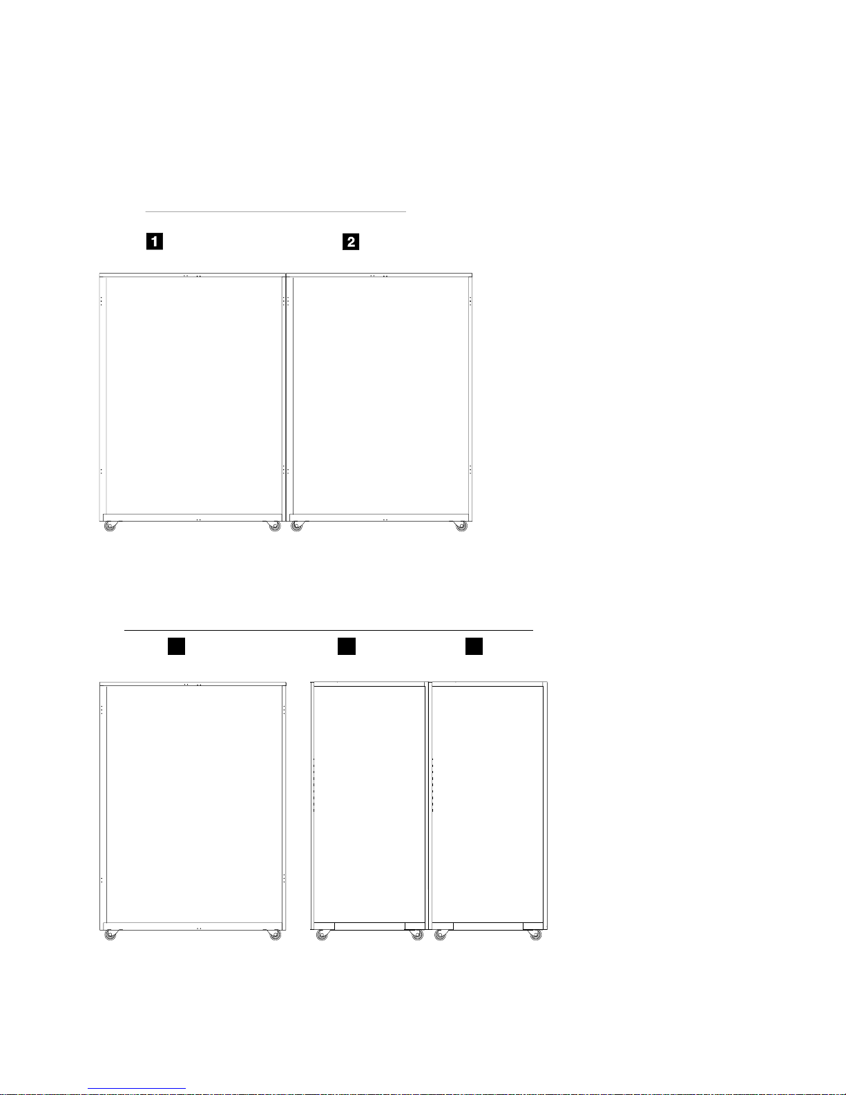
location code (R#-) indicate what rack they are mounted in. Reference Figure 1 on page 7 and
Figure 2 on page 7 the two possible subsystem configurations.
2. Locate the rack number (R#-) in the following list and go to the page or step indicated:
v R1- (2105 Model Exx or Fxx), go to “Rack Location Codes for DDM Bays in a 2105 Model
Exx/Fxx” on page 8
v R2- (2105 Expansion Enclosure), go to “Rack Location Codes for DDM Bays in a 2105
Expansion Enclosure” on page 9
v R2- (2105 Model 100), go to “Rack Location Codes for SSA DASD Model 020 or 040
Drawers in a 2105 Model 100” on page 11
6
VOLUME 3, ESS Service Guide
Page 23
Locations
v R3- (2105 Model 100), go to “Rack Location Codes for SSA DASD Model 020 or 040
Drawers in a 2105 Model 100” on page 11
v R4- (2105 Model 100), go to “Rack Location Codes for SSA DASD Model 020 or 040
Drawers in a 2105 Model 100” on page 11
2105 Subsystem (front View)
Rack 1
(R1- )
2105 Model
EXX/FXX
Figure 1. 2105 Model Exx/Fxx and Expansion Enclosure Rack Locations in a Subsystem (S007745n)
2105 Subsystem (front View)
Expansion Enclosure
Rack 2
(R2- )
2105
3
Rack 1
(R1- )
2105 Model
Exx/Fxx
Figure 2. 2105 Model Exx/Fxx with attached 2105 Model 100 Racks (S008855n)
Rack 2
4
(R2- )
2105 Model
100
2105 Model Exx/Fxx and Expansion Enclosure Locations, CHAPTER 7 7
Rack 3
5
(R3- )
2105 Model
100
Page 24

Locations
Rack Location Table
Use the following table to locate a DDM bay or SSA DASD Model 020 or 040 drawer in a 2105 Model
Exx/Fxx, 2105 Expansion Enclosure, or 2105 Expansion Enclosure.
Table 1. 2105 DDM bay and SSA DASD Model 020 and 040 Locations
Rack Location
Code
R1- Exx/Fxx Yes (all) Go to Figure 3 on page 9.
R2- Expansion
R2- 100 Yes (all) Go to Figure 5 on page 11.
R3- 100 Yes (all) Go to Figure 5 on page 11.
2105 Model DDM bays
Installed
(Rx-Ux-Wxx)
Yes (all) Go to Figure 4 on page 10.
Enclosure
7133 Drawers
Installed (Rx-Yxx)
DDM bay or SSA DASD Model 020
and 040 Location Diagram
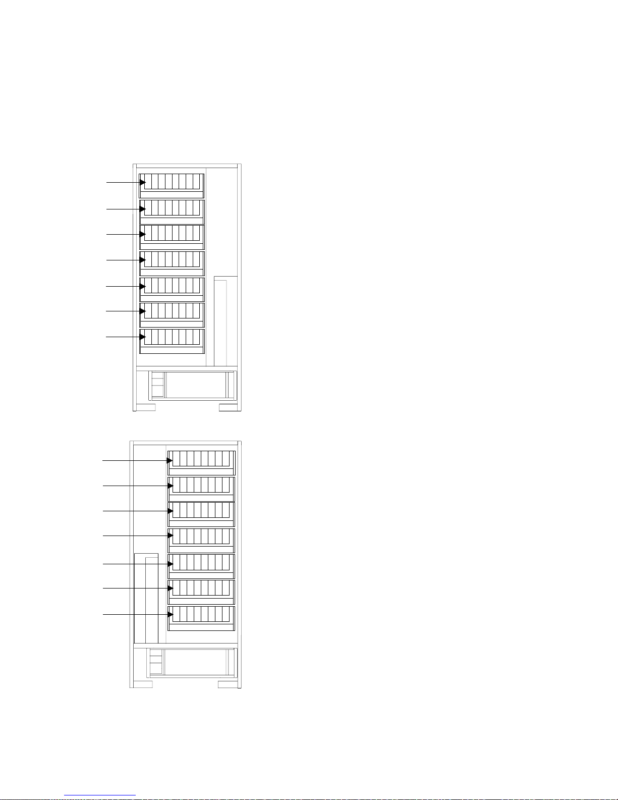
Rack Location Codes for DDM Bays in a 2105 Model Exx/Fxx
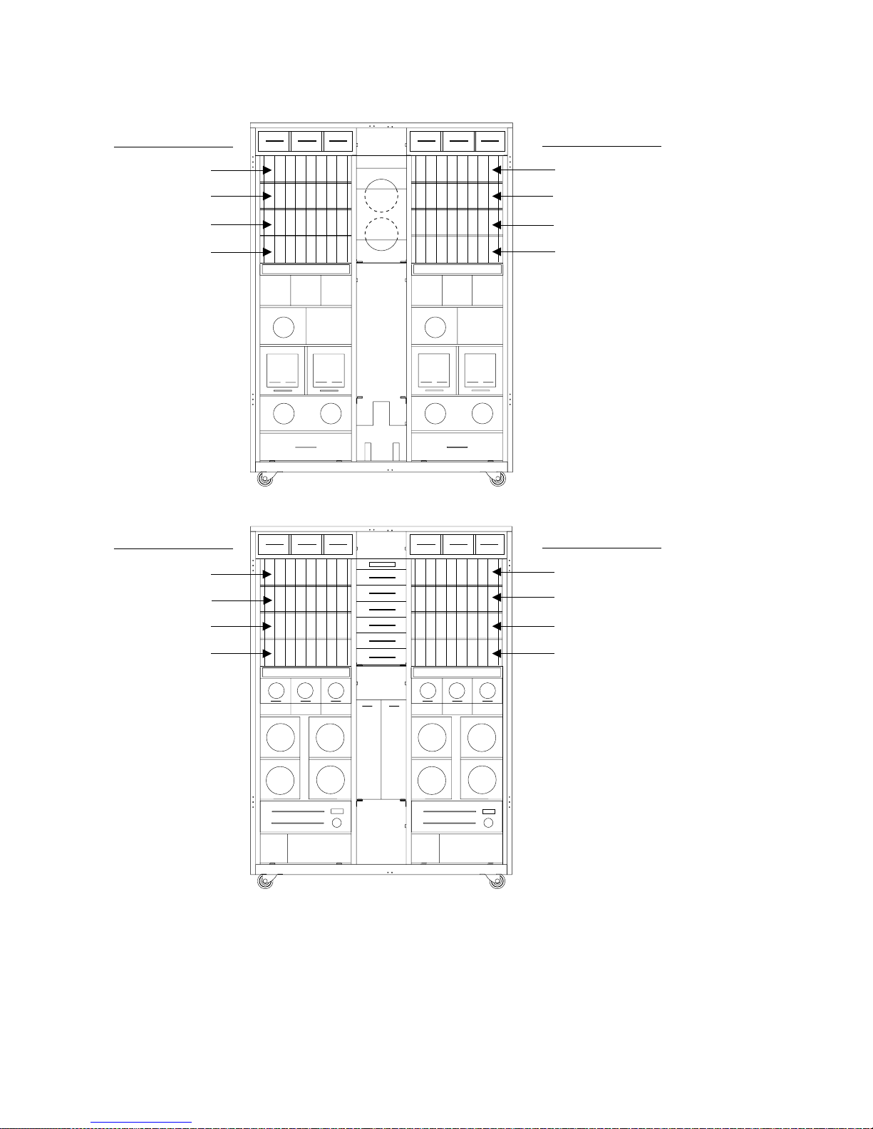
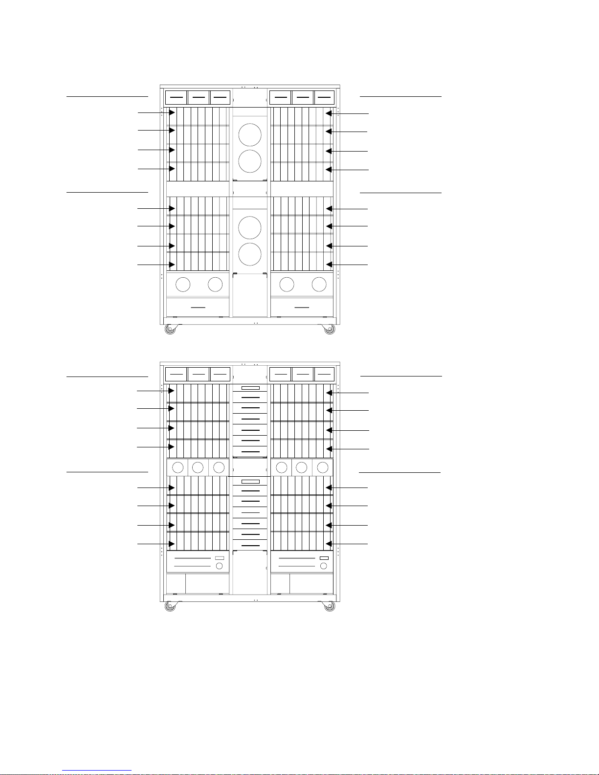
The following diagram shows the location codes of the DDM bays mounted in a 2105 Model Exx/Fxx.
8
VOLUME 3, ESS Service Guide
Page 25
(R1- )
Locations
Storage Cage 1 (-U1-)
R1-U1-W1
R1-U1-W2
R1-U1-W3
R1-U1-W4
Storage Cage 2 (-U2-)
1
2332445566778
Storage Cage 2 (-U2-)
R1-U2-W1
R1-U2-W2
R1-U2-W3
R1-U2-W4
Front View
Storage Cage 1 (-U1-)
R1-U2-W5
R1-U2-W6
R1-U2-W7
R1-U2-W8
Figure 3. R1- Location Codes for DDM Bays in a 2105 Model Exx/Fxx (S007740s)
1
8
Rear View
R1-U1-W5
R1-U1-W6
R1-U1-W7
R1-U1-W8
Rack Location Codes for DDM Bays in a 2105 Expansion Enclosure
The following diagram shows the location codes of the DDM bays mounted in a 2105 Expansion
Enclosure.
2105 Model Exx/Fxx and Expansion Enclosure Locations, CHAPTER 7 9
Page 26
Locations
Storage Cage 1 (-U1-)
2105 Expansion Enclosure (R2-)
Storage Cage 2 (-U2-)
R2-U1-W1
R2-U1-W2
R2-U1-W3
R2-U1-W4
Storage Cage 3 (-U3-)
R2-U3-W1
R2-U3-W2
R2-U3-W3
R2-U3-W4
Storage Cage 2 (-U2-)
R2-U2-W5
R2-U2-W6
1
2345678
12345678
R2-U2-W1
R2-U2-W2
R2-U2-W3
R2-U2-W4
Storage Cage 4 (-U4-)
R2-U4-W1
R2-U4-W2
R2-U4-W3
R2-U4-W4
Front View
Storage Cage 1 (-U1-)
R2-U1-W5
R2-U1-W6
R2-U2-W7
R2-U2-W8
Storage Cage 4 (-U4-)
R2-U4-W5
R2-U4-W6
R2-U4-W7
R2-U4-W8
R2-U1-W7
R2-U1-W8
Storage Cage 3 (-U3-)
R2-U3-W5
R2-U3-W6
R2-U3-W7
R2-U3-W8
Rear View
Figure 4. R2- and R3- Location Codes for DDM Bays in a 2105 Expansion Enclosure (S007741s)
10
VOLUME 3, ESS Service Guide
Page 27
Locations
Rack Location Codes for SSA DASD Model 020 or 040 Drawers in a 2105 Model
100
The following diagram shows the location codes of the SSA DASD Model 020 or 040 drawers mounted in
a 2105 Model 100.
2105 Model 100
(R2 or R3)
Rx-Y6
Rx-Y5
Rx-Y4
Rx-Y3
Rx-Y2
Rx-Y1
Rx-Y0
Rx-Y6
Rx-Y5
Rx-Y4
Rx-Y3
Rx-Y2
Rx-Y1
Rx-Y0
Front
View
Rear
View
Figure 5. R2- and R3 Location Codes for SSA DASD Model 020 or 040 Drawers in a 2105 Model 100 (S008942s)
2105 Model Exx/Fxx and Expansion Enclosure Locations, CHAPTER 7 11
Page 28
Locations
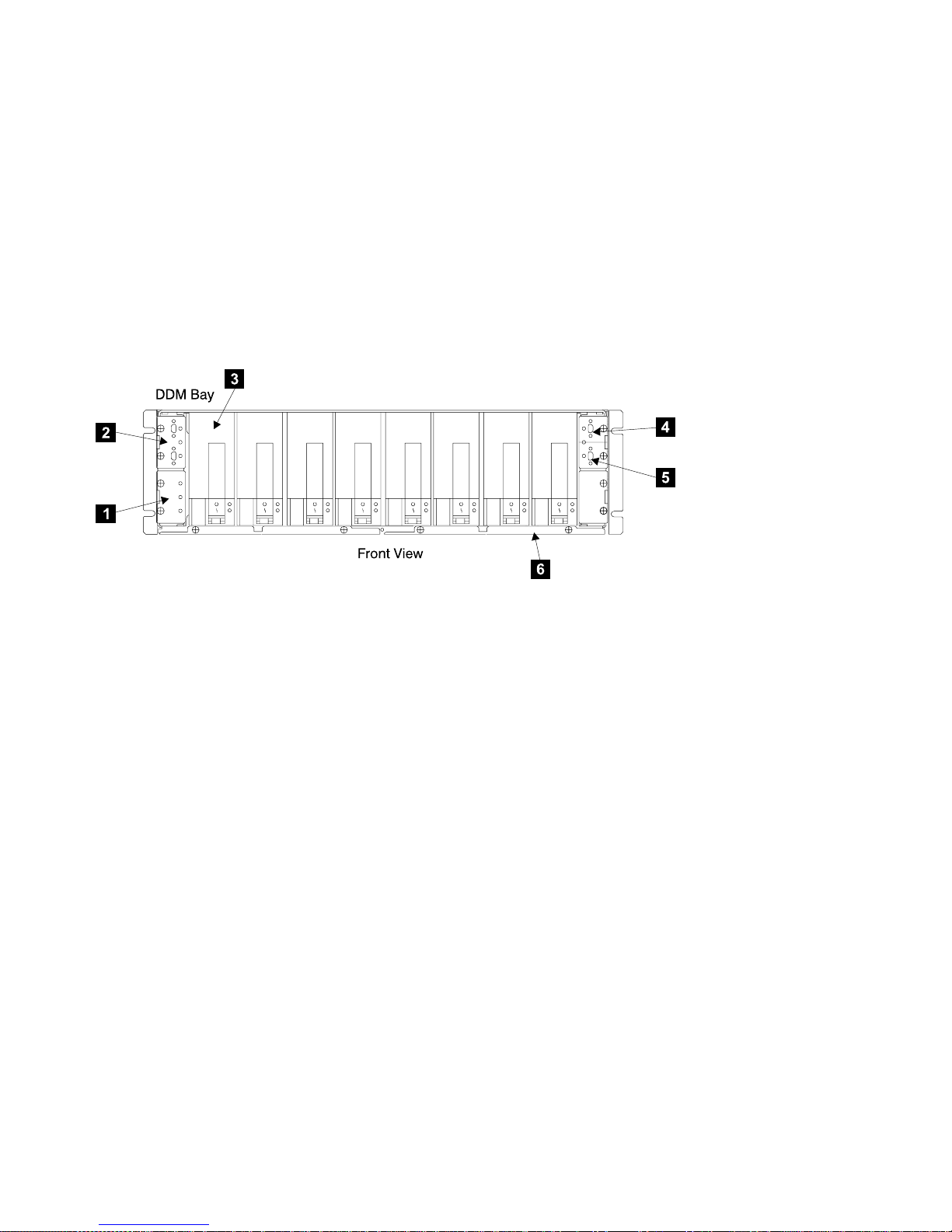
DDM Bay, Component Physical Location Codes
To locate a DDM bay in a 2105, see “Locating a DDM Bay or SSA DASD Model 020 or 040 Drawer in a
2105 Rack” on page 6.
v Controller card, lower left (Rx-Ux-Wx-C5) 1
v Host bypass card, upper left (Rx-Ux-Wx-C1) 2
v Disk Drive Module, DDM (DDM bay) (Rx-Ux-Wx-Dx) 3
See “DDM Bay, Disk Drive Module Location Codes”
v Passthrough card, upper right (upper) (Rx-Ux-Wx-C2) 4
v Passthrough card, upper right (lower) (Rx-Ux-Wx-C4) 5
v Frame, (DDM bay) (Rx-Ux-Wx-P1) 6
Figure 6. DDM bay Physical Location Codes (S008296l)
DDM Bay, Disk Drive Module Location Codes
To locate a DDM bay in a 2105, see “Locating a DDM Bay or SSA DASD Model 020 or 040 Drawer in a
2105 Rack” on page 6.
v (1) DDM 1, (Rx-Ux-Wx-D01)
v (2) DDM 2, (Rx-Ux-Wx-D02)
v (3) DDM 3, (Rx-Ux-Wx-D03)
v (4) DDM 4, (Rx-Ux-Wx-D04)
v (5) DDM 5, (Rx-Ux-Wx-D05)
v (6) DDM 6, (Rx-Ux-Wx-D06)
v (7) DDM 7, (Rx-Ux-Wx-D07)
v (8) DDM 8, (Rx-Ux-Wx-D08)
12
VOLUME 3, ESS Service Guide
Page 29
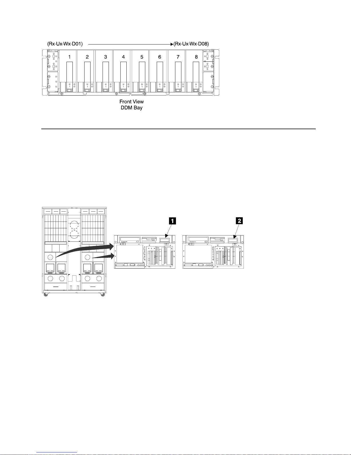
Figure 7. Disk Drive Locations in a DDM bay (S007706l)
Cluster Bay Location Codes, 2105 Model E10/E20
Location information for 2105 Model E10/E20 cluster bays follow:
Cluster Bay, Operator Panel Location Codes (E10/E20)
2105 Model E10/E20 2105 Model E10/E20
v Cluster Bay 1, operator panel, (R1-T1-L1) 1
v Cluster Bay 2, operator panel, (R1-T2-L1) 2
Locations
Cluster 1 Cluster 2
Front
View
Figure 8. Cluster Bay Operator Panel Locations (S007687m)
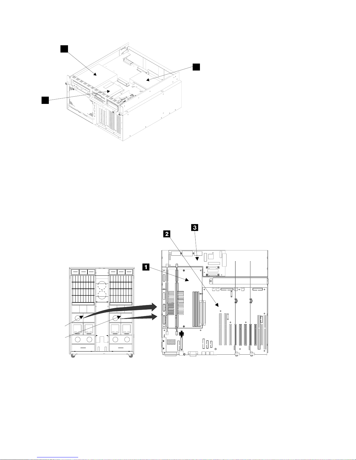
Cluster Bay, Drives Location Codes (E10/E20)
v Diskette drive, (R1-Tx-P2-D1) 1
v CD-ROM drive, (R1-Tx-P2-Z1-A3) 2
v SCSI hard drive, (R1-Tx-P2-Z1-A0) 3
2105 Model Exx/Fxx and Expansion Enclosure Locations, CHAPTER 7 13
Page 30
Locations
2
CD-ROM
Drive
3
SCSI Hard
Drive
1
Diskette
Drive
Front
Figure 9. Cluster Bay Drive Locations (S008316m)
Cluster Bay, System, I/O, and Power Planar Location Codes (E10/E20)
v System planar, (R1-Tx-P1) 1
v I/O planar, (R1-Tx-P2) 2
v Cluster Bay Power planar, (R1-Tx-P3) 3
CLUSTER 1
CLUSTER 2
Front
View
Figure 10. Cluster Bay Planar Locations (S008585n)
Cluster Bay, I/O Planar Battery Location Codes (E10/E20)
v I/O planar battery, (R1-Tx-P2-V2) 1
14
VOLUME 3, ESS Service Guide
Page 31

Figure 11. Cluster Bay I/O Planar Battery Locations (S008194n)
Locations
Cluster Bay, Service Processor Card Location Codes (E10/E20)
v Service processor card, (R1-Tx-P2-X1) 1
CLUSTER 1
CLUSTER 2
Front
View
Figure 12. Cluster Bay Service Processor Card Locations (S008586n)
Cluster Bay, 332 MHz CPU Card Location Codes (E10/E20)
v 332 MHz CPU card 1, (R1-Tx-P1-C1) 1
v 332 MHz CPU card 2, (R1-Tx-P1-C2) 2
2105 Model Exx/Fxx and Expansion Enclosure Locations, CHAPTER 7 15
Page 32

Locations
CLUSTER 1
CLUSTER 2
Front
View
Figure 13. Cluster Bay 332 MHz CPU Card Locations (S008587n)
332mhz CPU Cards
R1-Tx-P1-C2
R1-Tx-P1-C1
Cluster Bay, Memory Card Location Codes (E10/E20)
v Memory card 1, (R1-Tx-P1-M1) 1
v Memory card 2, (R1-Tx-P1-M2) 2
Cluster 1/2 Top View.
CLUSTER 1
CLUSTER 2
Front
View
Figure 14. Cluster Bay Memory Card Locations (S008588n)
16
VOLUME 3, ESS Service Guide
Front
Memory Cards
R1-Tx-P1-M1
R1-Tx-P1-M2
Page 33

Locations
Cluster Bay, Memory Card, Memory Module Location Codes (E10/E20)
v memory module 1, (R1-Tx-P1-Mx.1) 1
v memory module 2, (R1-Tx-P1-Mx.2) 2
v memory module 3, (R1-Tx-P1-Mx.3) 3
v memory module 4, (R1-Tx-P1-Mx.4) 4
v memory module 5, (R1-Tx-P1-Mx.5) 5
v memory module 6, (R1-Tx-P1-Mx.6) 6
v memory module 7, (R1-Tx-P1-Mx.7) 7
v memory module 8, (R1-Tx-P1-Mx.8) 8
v memory module 9, (R1-Tx-P1-Mx.9) 9
v memory module 10, (R1-Tx-P1-Mx.10) 10
v memory module 11, (R1-Tx-P1-Mx.11) 11
v memory module 12, (R1-Tx-P1-Mx.12) 12
v memory module 13, (R1-Tx-P1-Mx.13) 13
v memory module 14, (R1-Tx-P1-Mx.14) 14
v memory module 15, (R1-Tx-P1-Mx.15) 15
v memory module 16, (R1-Tx-P1-Mx.16) 16
Figure 15. Cluster Bay Memory Card Locations (S008192n)
2105 Model Exx/Fxx and Expansion Enclosure Locations, CHAPTER 7 17
Page 34

Locations
Figure 16. Cluster Bay Memory Card Memory Module Locations (S008208l)
Cluster Bay, SSA Device Card Location Codes (E10/E20)
v SSA device card, (R1-Tx-P2-K1) 1
v SSA device card, (R1-Tx-P2-K2) 2
v SSA device card, (R1-Tx-P2-K3) 3
v SSA device card, (R1-Tx-P2-K9) 4
Cluster 1/2
SSA Device Card
Connectors
B2
B1
A2
A1
CLUSTER 1
CLUSTER 2
Front
View
Figure 17. Cluster Bay SSA Device Card Locations (S008589m)
SSA Device Cards
R1-Tx-P2-K1-zz
1
2
R1-Tx-P2-K2-zz
3
R1-Tx-P2-K3-zz
R1-Tx-P2-K9-zz
4
Front View
Cluster Bay, SSA Device Card Dram Module Location Codes (E10/E20)
v SSA device card DRAM module, (R1-Tx-P2-Kx-M1) 1
18
VOLUME 3, ESS Service Guide
Page 35

Locations
1
FRONT
Figure 18. Cluster Bay SSA Device Card DRAM Module Locations (S008590l)
Cluster Bay, NVS Memory and Top Card Crossover Location Codes
(E10/E20)
v NVS memory card 1, (R1-Tx-P2-I5) 1
v NVS memory card 2, (R1-Tx-P2-I6) 2
v NVS top card crossover, (R1-Tx-P2-I5 to I6) 3
Cluster 1/2 Top View.
CLUSTER 1
CLUSTER 2
Front
View
Figure 19. Cluster Bay NVS Memory Card Locations (S008591n)
NVS Memory Cards
Front
R1-Tx-P2-I5
R1-Tx-P2-I6
Cluster Bay, NVS Cache Module Location Codes (E10/E20)
v NVS cache module 1, (R1-Tx-P2-Ly-M1) 1
v NVS cache module 2, (R1-Tx-P2-Ly-M2) 2
v NVS cache module 3, (R1-Tx-P2-Ly-M3) 3
Top Card
Crossover
2105 Model Exx/Fxx and Expansion Enclosure Locations, CHAPTER 7 19
Page 36

Locations
3
2
1
Front
Figure 20. Cluster Bay NVS Cache Module Locations (S008592m)
Cluster Bay, I/O Attachment Card Location Codes (E10/E20)
v I/O attachment card, (R1-Tx-P2-I4) 1
v I/O attachment card, (R1-Tx-P2-I7) 2
CLUSTER 1
CLUSTER 2
Front
View
Figure 21. Cluster Bay I/O Attachment Card Locations (S008593n)
I/O Attachment Cards
R1-Tx-P2-I4
R1-Tx-P2-I7
Cluster Bay, Cable Location Codes (E10/E20)
v Cluster Bay 1, (R1-T1- ) or Cluster Bay 2, (R1-T2- )
– Serial Interface Cable (S1 = R1-Tx-P2-S1.1) (S2 = R1-Tx-P2-S2.1)
– Serial Interface Cable (S1), (R1-Tx-P2-S3.1)
– Power Planar Cable (IB11), (R1-Tx-P3-IB11.1)
– Power Planar Cable (IB12), (R1-Tx-P3-IB12.1)
– Power Planar Cable (IB15), (R1-Tx-P3-IB15.1)
– Service Processor Card Cable, (R1-Tx-P2-X1.1)
20
VOLUME 3, ESS Service Guide
Page 37

Locations
– SCSI Drive Signal Cable, (R1-Tx-P2-Z1.1)
– CPU Card 1 Cable, (R1-Tx-P1-C1.1)
– CPU Card 2 Cable, (R1-Tx-P1-C2.1)
– Cluster Bay Power Planar to Docking Connector Cable, (R1-Tx-N1.1)
– NVS Card Cable (Card 1 = R1-Tx-P1-M1.1) (Card 2 = R1-Tx-P1-M2.1)
– Cluster Operator Panel Cable, (R1-Tx-P2-L1.1)
– Diskette Drive Signal Cable, (R1-Tx-P2-D1.1)
– Cluster Drive Power Cable, (R1-Tx-P3-IB16.1)
v Use the cluster cable removal and replacement procedure to locate any of the cables listed above, see
″Cables, Cluster Bay″ in chapter 4 of the Enterprise Storage Server Service Guide, Volume 2.
Cluster Bay Location Codes, 2105 Model F10/F20
Location information for 2105 Model F10/F20 cluster bays follow:
Cluster Bay, Operator Panel Location Codes (F10/F20)
v 2105 Model F10/F20:
– Cluster Bay 1, operator panel, (R1-T1-L1) 1
– Cluster Bay 2, operator panel, (R1-T2-L1) 2
Cluster 1 Cluster 2
Front
View
Figure 22. Cluster Bay Operator Panel (S008772m)
Cluster Bay, Drives Location Codes (F10/F20)
v Diskette drive (R1-Tx-P2-D1) 1
v CD-ROM drive (R1-Tx-P2-Z1-A3) 2
v SCSI hard drive (R1-Tx-P2-Z1-A0) 3
2105 Model Exx/Fxx and Expansion Enclosure Locations, CHAPTER 7 21
Page 38

Locations
2
CD-ROM
Drive
3
SCSI Hard
Drive
1
Diskette
Drive
Front
Figure 23. Cluster Bay Drive Locations (S008776m)
Cluster Bay, System, I/O, and Power Planars Location Codes (F10/F20)
v System planar (R1-Tx-P1) 1
v I/O planar (R1-Tx-P2) 2
v Cluster Bay Power planar (R1-Tx-P3) 3
v Communications cables 4
v SSA device card and I/O attachment card cables 5
CLUSTER 1
CLUSTER 2
Front
View
Figure 24. Cluster Bay Planar Locations (S008778n)
22
VOLUME 3, ESS Service Guide
Page 39

Cluster Bay, I/O Planar Battery Location Codes (F10/F20)
v I/O planar battery (R1-Tx-P2-V2) 1
Cluster 1/2 Top View.
CLUSTER 1
CLUSTER 2
+
Locations
Front
View
Figure 25. I/O Planar Battery Removal (S008790n)
Front
Cluster Bay, 255 MHz CPU Card Location Codes (F10/F20)
v 255 MHz CPU card 1, (R1-Tx-P1-C1) 1
v 255 MHz CPU card 2, (R1-Tx-P1-C2) 2
CLUSTER 1
CLUSTER 2
Front
View
Figure 26. 2105 Model F10/F20 Cluster Bay Locations (S008781n)
225mhz CPU Cards
Front
R1-Tx-P1-C2
R1-Tx-P1-C1
2105 Model Exx/Fxx and Expansion Enclosure Locations, CHAPTER 7 23
Page 40

Locations
Cluster Bay, Memory Card Location Codes (F10/F20)
v Memory card 1, (R1-Tx-P1-M1) 1
v Memory card 2, (R1-Tx-P1-M2) 2
Cluster 1/2 Top View.
CLUSTER 1
CLUSTER 2
Front
View
Figure 27. 2105 Model F10/F20 Cluster Bay Locations (S008782n)
Memory Cards
R1-Tx-P1-M1
R1-Tx-P1-M2
Front
Cluster Bay, Memory Card, Memory Module Location Codes (F10/F20)
v memory module 1 (R1-Tx-P1-Mx.1) 1
v memory module 2 (R1-Tx-P1-Mx.2) 2
v memory module 3 (R1-Tx-P1-Mx.3) 3
v memory module 4 (R1-Tx-P1-Mx.4) 4
v memory module 5 (R1-Tx-P1-Mx.5) 5
v memory module 6 (R1-Tx-P1-Mx.6) 6
v memory module 7 (R1-Tx-P1-Mx.7) 7
v memory module 8 (R1-Tx-P1-Mx.8) 8
v memory module 9 (R1-Tx-P1-Mx.9) 9
v memory module 10 (R1-Tx-P1-Mx.10) 10
v memory module 11 (R1-Tx-P1-Mx.11) 11
v memory module 12 (R1-Tx-P1-Mx.12) 12
v memory module 13 (R1-Tx-P1-Mx.13) 13
v memory module 14 (R1-Tx-P1-Mx.14) 14
v memory module 15 (R1-Tx-P1-Mx.15) 15
v memory module 16 (R1-Tx-P1-Mx.16) 16
24
VOLUME 3, ESS Service Guide
Page 41

CLUSTER 1
CLUSTER 2
Locations
Cluster 1/2 Top View.
Front
View
Figure 28. 2105 Model F10/F20 Cluster Bay Locations (S008782n)
Figure 29. 2105 Model F10/F20 Cluster Bay Memory Card Memory Module Locations (S008208l)
Memory Cards
R1-Tx-P1-M1
R1-Tx-P1-M2
Front
Cluster Bay, SSA Device Card Location Codes (F10/F20)
v SSA device card (R1-Tx-P2-K1) 1
v SSA device card (R1-Tx-P2-K2) 2
v SSA device card (R1-Tx-P2-K3) 3
v SSA device card (R1-Tx-P2-K4) 4
2105 Model Exx/Fxx and Expansion Enclosure Locations, CHAPTER 7 25
Page 42

Locations
Cluster 1/2 (Model F10/F20)
SSA Device Card
Connectors
B2
B1
A2
A1
CLUSTER 1
CLUSTER 2
Front
View
Figure 30. SSA Device Card Removal (S008773m)
SSA Device Cards
1
R1-Tx-P2-K1-yy
2
R1-Tx-P2-K2-yy
R1-Tx-P2-K3-yy
3
4
R1-Tx-P2-K4-yy
Front
View
Cluster Bay, SSA Device Card Dram Module Location Codes (F10/F20)
v SSA device card DRAM module, (R1-Tx-P2-Kx-M1) 1
1
FRONT
Figure 31. Cluster Bay SSA Device Card DRAM Module Locations (S008590l)
Cluster Bay, NVS Memory and Top Card Crossover Location Codes
(F10/F20)
v NVS memory card 1, (R1-Tx-P2-I6) 1
v NVS memory card 2, (R1-Tx-P2-I7) 2
v NVS top card crossover, (R1-Tx-P2-I6 to I7) 3
26
VOLUME 3, ESS Service Guide
Page 43

CLUSTER 1
CLUSTER 2
Locations
Cluster 1 /2 Top View.
Front
Front
View
Figure 32. 2105 Model F10/F20 Cluster Bay Locations (S008783n)
NVS Memory Cards
R1-Tx-P2-I6
R1-Tx-P2-I7
Cluster Bay, NVS Cache Module Location Codes (F10/F20)
v NVS cache module 1, (R1-Tx-P2-Ly-M1) 1
v NVS cache module 2, (R1-Tx-P2-Ly-M2) 2
v NVS cache module 3, (R1-Tx-P2-Ly-M3) 3
3
2
1
Top Card
Crossover
R1-Tx-P2-I6 to I7
Front
Figure 33. Cluster Bay NVS Remove and Replace (S008592m)
Cluster Bay, I/O Attachment Card Location Codes (F10/F20)
v I/O attachment card (R1-Tx-P2-I5) 1
v I/O attachment card (R1-Tx-P2-I8) 2
2105 Model Exx/Fxx and Expansion Enclosure Locations, CHAPTER 7 27
Page 44

Locations
CLUSTER 1
CLUSTER 2
I/O Attachment Cards
Front
View
Figure 34. 2105 Model F10/F20 Cluster Bay Locations (S008780n)
R1-Tx-P2-I5
R1-Tx-P2-I8
Front
Cluster Bay, Fan Location Codes (F10/F20)
v Cluster 1, cluster bay fan, (R1-T1-F5)
v Cluster 2, cluster bay fan, (R1-T2-F5)
(R1- )
Cluster 1
(R1-T1- )
Front View
Figure 35. 2105 Model E10/E20 Cluster Locations (S008091m)
Cluster 2
(R1-T2- )
28
VOLUME 3, ESS Service Guide
Page 45

1
AIRFLOW
Figure 36. Cluster Bay Fan Removal (S008808m)
Locations
Cluster Bay, Cable Location Codes (F10/F20)
v Cluster Bay 1, (R1-T1- ) or Cluster Bay 2, (R1-T2- )
– Serial Interface Cable (S1/S2), (S1 = R1-Tx-P2-S1.1) (S2 = R1-Tx-P2-S2.1)
– Serial Interface Cable (S3), (R1-Tx-P2-S3.1)
– Power Planar Cable (IB11), (R1-Tx-P3-IB11.1)
– Power Planar Cable (IB12), (R1-Tx-P3-IB12.1)
– Power Planar Cable (IB13), (R1-Tx-P3-IB13.1)
– Power Planar Cable (IB14), (R1-Tx-P3-IB14.1)
– Power Planar Cable (IB15), (R1-Tx-P3-IB15.1)
– SCSI Drive Signal Cable, (R1-Tx-P2-Z1.1)
– Cluster Bay Power Planar to Docking Connector Cable, (R1-Tx-N1.1)
– Cluster Operator Panel Cable, (R1-Tx-P2-L1.1)
– Diskette Drive Signal Cable, (R1-Tx-P2-D1.1)
– Cluster Internal Power Cable, (R1-Tx-P3-IB17.1)
– Cluster Drive Power Cable, (R1-Tx-P3-IB18.1)
– NVS Crossover to I/O Attachment Card Cable, (R1-Tx-P2-I5 to I6)
Use the cluster cable removal and replacement procedure to locate any of the cables listed above, see
″Cables, Cluster Bay″ in chapter 4 of the Enterprise Storage Server Service Guide, Volume 2.
SSA DASD Drawer Component Physical Location Codes, Model 020
Drawer
To locate a SSA DASD Model 020 drawer in a 2105, see “Locating a DDM Bay or SSA DASD Model 020
or 040 Drawer in a 2105 Rack” on page 6.
1 Drawer power control panel, (Rx-Yxx-C9)
2 Disk Drive Module (front), DDM (Model 020 drawer) (Rx-Yxx-Dxx),
See “7133 Drawer, Disk Drive Module Location Codes” on page 31
2105 Model Exx/Fxx and Expansion Enclosure Locations, CHAPTER 7 29
Page 46

Locations
3 Back-power card, (left) (Rx-Yxx-C5)
4 Front backplane assembly, (Rx-Yxx-P1)
5 Back backplane assembly (Rx-Yxx-P2)
6 Bypass card, upper right (Rx-Yxx-C2)
7 Bypass card, lower right (Rx-Yxx-C6)
8 Disk Drive Module, (rear) DDM (Model 020 drawer) (Rx-Yxx-Dxx),
See “7133 Drawer, Disk Drive Module Location Codes” on page 31
9 Fan-and-power-supply assembly, (Rx-Yxx-V3)
10 Fan-and-power-supply assembly, (Rx-Yxx-V2)
11 Fan-and-power-supply assembly, (Rx-Yxx-V1)
12 Bypass card, upper left, (Rx-Yxx-C1)
13 Bypass card, lower left (Rx-Yxx-C5)
14 Back-power card, (right) (Rx-Yxx-C6)
15 Power-distribution tray, (right) (Rx-Yxx-V9)
16 Power-distribution tray, (left) (Rx-Yxx-V10)
Figure 37. 7133 Model 020 Physical Location Codes (S008297n)
SSA DASD Drawer Component Physical Location Codes, Model 040
Drawer
To locate a SSA DASD Model 040 drawer in a 2105, see “Locating a DDM Bay or SSA DASD Model 020
or 040 Drawer in a 2105 Rack” on page 6.
1 Controller card, (Rx-Yxx--CA)
2 Bypass card, lower right (Rx-Yxx-C6)
3 Bypass card, upper right (Rx-Yxx-C2)
4 Frame assembly, (Rx-Yxx-P1)
30
VOLUME 3, ESS Service Guide
Page 47

Locations
5 Disk Drive Module, (rear) DDM (Model 040 drawer) (Rx-Yxx-Dxx)
See “7133 Drawer, Disk Drive Module Location Codes”
6 Power Supply 2, (Rx-Yxx-V2)
7 Power Supply 1, (Rx-Yxx-V1)
8 Bypass card, upper left (Rx-Yxx-C1)
9 Bypass card, lower left (Rx-Yxx-C5)
10 Disk Drive Module, (front) DDM (Model 040 drawer) (Rx-Yxx-Dxx)
See “7133 Drawer, Disk Drive Module Location Codes”
11 Fan assembly, right (Rx-Yxx-F3)
12 Fan assembly, center (Rx-Yxx-F2)
13 Fan assembly, left (Rx-Tx-F1)
14 Operator panel assembly (The drawer operator panel on 7133 Model 040 drawer is not used
during drawer isolation procedures.) (Rx-Tx-L1)
Figure 38. SSA DASD Model 040 Physical Location Codes (S008298n)
7133 Drawer, Disk Drive Module Location Codes
To locate a SSA DASD Model 020 or 040 drawer in a 2105, see “Locating a DDM Bay or SSA DASD
Model 020 or 040 Drawer in a 2105 Rack” on page 6.
v ( 1) DDM 1, (R2-Yxx-D01)
v ( 2) DDM 2, (R2-Yxx-D02)
v ( 3) DDM 3, (R2-Yxx-D03)
v ( 4) DDM 4, (R2-Yxx-D04)
2105 Model Exx/Fxx and Expansion Enclosure Locations, CHAPTER 7 31
Page 48

Locations
v ( 5) DDM 5, (R2-Yxx-D05)
v ( 6) DDM 6, (R2-Yxx-D06)
v ( 7) DDM 7, (R2-Yxx-D07)
v ( 8) DDM 8, (R2-Yxx-D08)
v ( 9) DDM 9, (R2-Yxx-D09)
v (10) DDM 10, (R2-Yxx-D10)
v (11) DDM 11, (R2-Yxx-D11)
v (12) DDM 12, (R2-Yxx-D12)
v (13) DDM 13, (R2-Yxx-D13)
v (14) DDM 14, (R2-Yxx-D14)
v (15) DDM 15, (R2-Yxx-D15)
v (16) DDM 16, (R2-Yxx-D16)
Figure 39. Disk Drive Module Locations in a SSA DASD Drawer (S007705n)
32
VOLUME 3, ESS Service Guide
Page 49

2105 Model Exx/Fxx SSA Device Card Location Codes
Locations
Front
View
Cluster 1
(R1-T1-_)
Cluster 1/2 (Model Exx/Fxx)
SSA Device Cards
R1-Tx-P2-K1-yy
R1-Tx-P2-K2-yy
R1-Tx-P2-K3-yy
R1-Tx-P2-K4-yy
(Model F10/F20 only)
R1-Tx-P2-K9-yy
(Model E10/E20 only)
Cluster 2
(R1-T2-_)
SSA Device Card
Connectors
B2
B1
A2
A1
Front View
Figure 40. Cluster Bay and SSA Device Card Locations (S008178q)
2105 Model Exx/Fxx and Expansion Enclosure Locations, CHAPTER 7 33
Page 50

Locations
2105 Model Exx/Fxx SCSI Host Card Location Codes
SCSI
Connectors
ZA
ZB
Front
View
Host
Bays
R1-B1 R1-B2
Ultra SCSI Host Cards
Card 1, R1-Bx-H1
Card 2, R1-Bx-H2
Card 3, R1-Bx-H3
Card 4, R1-Bx-H4
ZA/LINK 00
ZB/LINK 01
R1-B3 R1-B4
ESCON Host Cards
Card 1, R1-Bx-H1
Card 2, R1-Bx-H2
Card 3, R1-Bx-H3
Card 4, R1-Bx-H4
ESCON Link
Connectors
Fibre Channel Host Cards
Card 1, R1-Bx-H1
Card 2, R1-Bx-H2
Card 3, R1-Bx-H3
Card 4, R1-Bx-H4
Fibre Channel Card Type
(Long Wave Card)
LW
(Short Wave Card)
SW
Fibre Link Connectors
Link A
Figure 41. 2105 Model Exx/FxxHost Bay SCSI Card Locations (S008024r)
Locating an SSA Cable
Use the information on this page to locate each end of an SSA cable. There are four possible SSA cable
connection configurations:
v SSA device card to DDM bay, (R1-Tx-P2-Kx-yy to Rx-Ux-Wxx-Jxx)
v SSA device card to 7133, (R1-Tx-P2-Kx-yy to R2-Yx-Jxx)
v DDM bay to DDM bay, (Rx-Ux-Wxx-Jxx to Rx-Ux-Wxx-Jxx)
34
VOLUME 3, ESS Service Guide
Page 51

Locations
v 7133 to 7133, (R2-Yx-Jxx to R2-Yx-Jxx)
The cables in each SSA cable loop are indicated by colored tape near the SSA cable connectors. See,
“Locating an SSA Cable Loop Using Colored Labels” on page 36 for the color associated with each SSA
loop.
SSA Device Card and Connector Locations
The SSA device card and connector location codes are in the format R1-Tx-P2-Kx-yy, where:
v R1 is rack 1 (2105 Model E10/E20)
v Tx is the cluster bay, 1 or 2
v P2 is cluster bay planar 2
v Kx is the card location slot, 1, 2, 3, or 9
v yy is the cable connector, A1, A2, B1, or B2
To locate an SSA device card and cable connector, see Figure 42.
Cluster 1/2 (Model Exx/Fxx)
SSA Device Card
Connectors
B2
B1
A2
A1
CLUSTER 1
CLUSTER 2
Front
View
Figure 42. Cluster Bay SSA Device Card and SSA Connector Locations (S008022m)
SSA Device Cards
R1-Tx-P2-K1-yy
R1-Tx-P2-K2-yy
R1-Tx-P2-K3-yy
R1-Tx-P2-K4-yy
(Model F10/F20 only)
R1-Tx-P2-K9-yy
(Model E10/E20 only)
Front View
DDM Bay SSA Connector Locations
The DDM bay SSA connector location codes are in the format Rx-Ux-Wxx-Jxx, where:
v Rx is the rack, 1 or 2
v Ux is the storage cage, 1, 2, 3, or 4
v Wxx istheDDMbay,1,2,3,4,5,6,7,or8
v Jxx is the DDM bay cable connector, JC, J1, JD, or J8
To locate an DDM bay in a 2105 rack, see “Locating a DDM Bay or SSA DASD Model 020 or 040 Drawer
in a 2105 Rack” on page 6. To locate the 7133 SSA cable connector, see Figure 43 on page 36.
2105 Model Exx/Fxx and Expansion Enclosure Locations, CHAPTER 7 35
Page 52

Locations
Figure 43. DDM bay and SSA Cable Connector Locations (S007693l)
7133 Drawer and SSA Connector Locations
The 7133 drawer SSA connector location codes are in the format Rx-Yx-Jxx, where:
v Rx is rack 2, 3, or 4
v Yx is the 7133, 1, 2, 3, 4, 5, 6, 7, or 8
v Jxx is the 7133 cable connector, J4, J5, J8, J9, J1, J16, J13, or J12
To locate a 7133 drawer, see “Locating a DDM Bay or SSA DASD Model 020 or 040 Drawer in a 2105
Rack” on page 6. To locate the 7133 SSA cable connector, see Figure 44.
Figure 44. 7133 Drawer and SSA Cable Connector Locations (S007651l)
Locating an SSA Cable Loop Using Colored Labels
All of the SSA cables in the 2105 subsystem have colored tape on the cable near each connector. The
short cables that run between adjacent DDM bays do not have colored tape. All of these connectors on an
SSA loop should have the same color of tape. See Table 2 on page 37 for the color of these SSA loop
connectors. All of these connectors on any DDM bay or SSA DASD drawer should have the same color
tape.
All of the SSA cables that are pre-installed by manufacturing will have the colored tape. The loop that the
short cables are part of can easily be determined by looking at the cables on the other end of the DDM
bays. When SSA cables are added, replaced, or moved (reconfigured) in the field, the correct colored tape
should be added to each cable.
36
VOLUME 3, ESS Service Guide
Page 53

Locations
Table 2. SSA Cable Loop Color Marking
SSA Device Card Loop A (Connectors A1 and A2) Loop B (Connectors B1 and B2)
K1, (R1-T1-K1 and R1-T2-K1) Green Red
K2, (R1-T1-K2 and R1-T2-K2) Gray Orange
K3, (R1-T1-K3 and R1-T2-K3) Violet Yellow
K4 (2105 Model F10/F20 only),
(R1-T1-K4 and R1-T2-K4)
K9 (2105 Model E10/E20 only),
(R1-T1-K9 and R1-T2-K9)
Blue Brown
Blue Brown
Locating a CPI Cable Using Colored Labels
All of the CPI cables in the 2105 subsystem have colored tape on the cable near each connector. See
Figure 45 on page 39. All of these connectors on an CPI should have the same color of tape. See Table 3
for the color of these CPI connectors.
All of the CPI cables that are pre-installed by manufacturing will have the colored tape. When CPI cables
are replaced in the field, the correct colored tape should be added to each cable.
Go to the correct cluster bay model table:
v 2105 Model E10/E20, Table 3
v 2105 Model F10/F20, Table 4 on page 38
Table 3. CPI Cable Locations and Color Marking (2105 Model E10/E20)
CPI Cable Location Code Cable Cluster Bay
Connector
R1-T1-P2-I4/JB.1 Cluster Bay 1, slot 4-B
(local)
R1-T1-P2-I7/JB.1 Cluster Bay 1, slot 7-B
(local)
R1-T1-P2-I4/JA.1 Cluster Bay 1, slot 4-A
(remote)
R1-T1-P2-I7/JA.1 Cluster Bay 1, slot 7-A
(remote)
R1-T2-P2-I4/JB.1 Cluster Bay 2, slot 4-B
(local)
R1-T2-P2-I7/JB.1 Cluster Bay 2, slot 7-B
(local)
R1-T2-P2-I4/JA.1 Cluster Bay 2, slot 4-A
(remote)
R1-T2-P2-I7/JA.1 Cluster Bay 2, slot 7-A
(remote)
Cable Host Bay Connector Cable Connector Color
Host Bay 1-B (local) Green
Host Bay 2-B (local) Yellow
Host Bay 3-A (remote) Gray
Host Bay 4-A (remote) Violet
Host Bay 3-B (local) Red
Host Bay 4-B (local) Blue
Host Bay 1-A (remote) Orange
Host Bay 2-A (remote) Brown
2105 Model Exx/Fxx and Expansion Enclosure Locations, CHAPTER 7 37
Page 54

Locations
Table 4. CPI Cable Locations and Color Marking (2105 Model F10/F20)
CPI Cable Location Code Cable Cluster Bay
Connector
R1-T1-P2-I5/JB.1 Cluster Bay 1, slot 5-B
(local)
R1-T1-P2-I8/JB.1 Cluster Bay 1, slot 8-B
(local)
R1-T1-P2-I5/JA.1 Cluster Bay 1, slot 5-A
(remote)
R1-T1-P2-I8/JA.1 Cluster Bay 1, slot 8-A
(remote)
R1-T2-P2-I5/JB.1 Cluster Bay 2, slot 5-B
(local)
R1-T2-P2-I8/JB.1 Cluster Bay 2, slot 8-B
(local)
R1-T2-P2-I5/JA.1 Cluster Bay 2, slot 5-A
(remote)
R1-T2-P2-I8/JA.1 Cluster Bay 2, slot 8-A
(remote)
Cable Host Bay Connector Cable Connector Color
Host Bay 1-B (local) Green
Host Bay 2-B (local) Yellow
Host Bay 3-A (remote) Gray
Host Bay 4-A (remote) Violet
Host Bay 3-B (local) Red
Host Bay 4-B (local) Blue
Host Bay 1-A (remote) Orange
Host Bay 2-A (remote) Brown
38
VOLUME 3, ESS Service Guide
Page 55

Primary Power Supply, 2105 Model Exx/Fxx and Expansion Enclosure
210E Model E10/E20 Clusters
Gray Violet
Cluster 1 (R1-T1- )
Orange Brown
Cluster 2 (R1-T2- )
210E Model F10/F20 Clusters
Cluster 1 (R1 - T1 - )
Bay 1 (B1) Bay 2 (B2)
Green Yellow
Gray
Green Yellow
Violet
Cluster 2 (R1 - T2 - )
Bay 3 (B3) Bay 4 (B4)
Red Blue
Orange
Brown
Red Blue
Orange Green Brown Yellow
Figure 45. CPI Cable Connector Color Coding (S008292r)
Primary Power Supply Location Codes, 2105 Model Exx/Fxx and
Expansion Enclosure
v 2105 Model Exx/Fxx:
– Primary power supply 1, right (R1-V1) 1
– Primary power supply 2, left (R1-V2) 2
v 2105 Expansion Enclosure:
– Primary power supply 1, right (R2-V1) 3
– Primary power supply 2, left (R2-V2) 4
Gray Red
2105 Model Exx/Fxx and Expansion Enclosure Locations, CHAPTER 7 39
Violet
Blue
Page 56

Primary Power Supply, 2105 Model Exx/Fxx and Expansion Enclosure
(R1- )
12
PPS-2
Rear View
Figure 46. 2105 Model Exx/Fxx and Expansion Enclosure Primary Power Supply Locations (S008665m)
CB2
CB3
J7-3
CB4 CB5
J7-4 J7-5
CB1
J1 J2 J3 J4
J7-1 J7-2
PPS-1
4
PPS-2
CB00
(R2- )
Rear View
3
PPS-1
J5A J5B J6
Rear
View
Figure 47. Primary Power Supply Connector and CB Locations (S008496l
Primary Power Supply Fan Locations, 2105 Model Exx/Fxx and
Expansion Enclosure
v 2105 Model E10/E20:
– Primary Power Supply 1, Fan 1, (R1-V1-F1) 1
– Primary Power Supply 1, Fan 2, (R1-V1-F2) 2
– Primary Power Supply 2, Fan 1, (R1-V2-F1) 3
– Primary Power Supply 2, Fan 2, (R1-V2-F2) 4
v 2105 Expansion Enclosure:
– Primary Power Supply 1, Fan 1, (R2-V1-F1) 5
– Primary Power Supply 1, Fan 2, (R2-V1-F2) 6
– Primary Power Supply 2, Fan 1, (R2-V2-F1) 7
– Primary Power Supply 2, Fan 2, (R2-V2-F2) 8
40
VOLUME 3, ESS Service Guide
Page 57
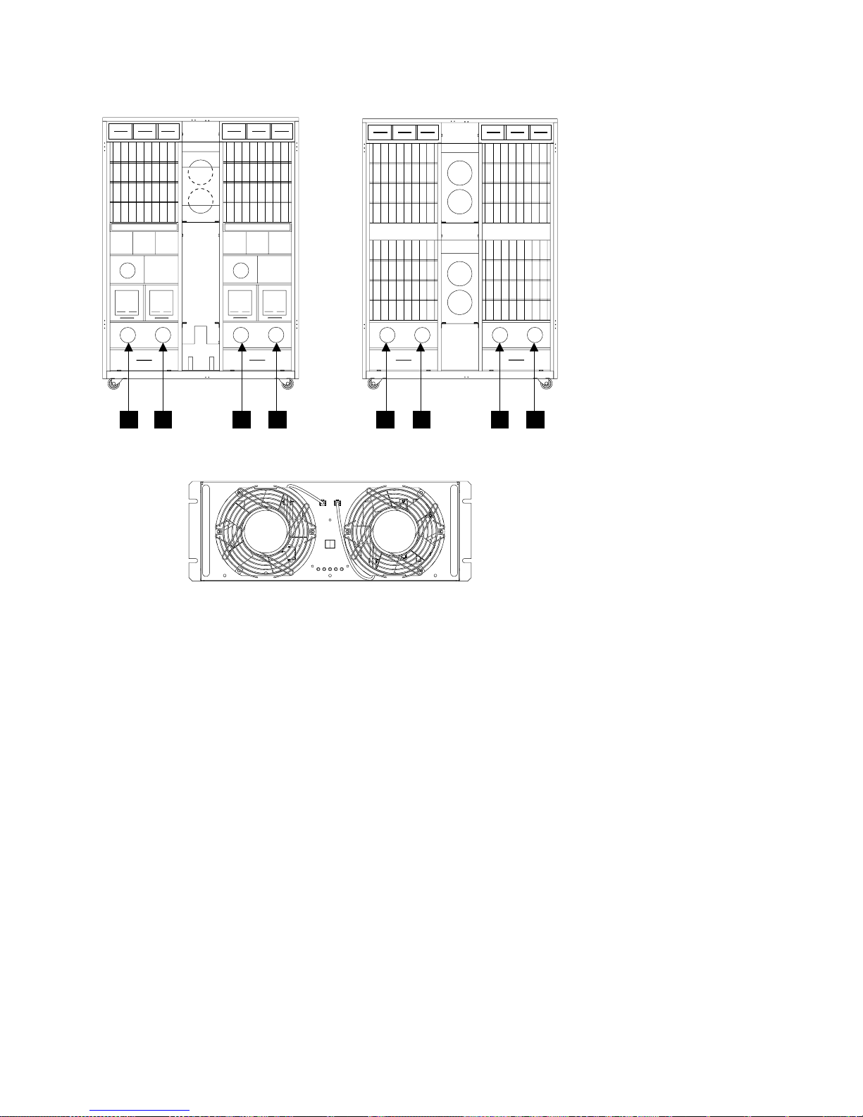
390 V Battery Set Locations, 2105 Model Exx/Fxx and Expansion Enclosure
(R1- )
Front View Front View
21
PPS 1/2
3
4
.
J8 J9
5
(R2- )
6
8
7
Front View
Figure 48. Primary Power Supply Fan Locations (S008669p)
390 V Battery Set Locations, 2105 Model Exx/Fxx and Expansion
Enclosure
v 2105 Model E10/E20:
– 390 V Battery 1, (R1-V3) 1
– 390 V Battery 2, (R1-V4) 2
v 2105 Expansion Enclosure:
– 390 V Battery 1, (R2-V3) 3
– 390 V Battery 2, (R2-V4) 4
2105 Model Exx/Fxx and Expansion Enclosure Locations, CHAPTER 7 41
Page 58
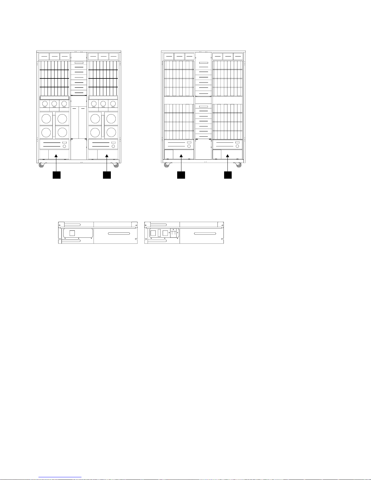
390 V Battery Set Locations, 2105 Model Exx/Fxx and Expansion Enclosure
(R2- )(R1- )
Rear View Rear View
12
4
3
Battery 2
Figure 49. 390 V Battery Set Locations (S009025)
Battery 1
Rack, 2105 Model Exx/Fxx and Expansion Enclosure Storage Cage
Power Supply Location Codes
v 2105 Model E10/E20:
– Storage cage 1 and 2:
- Storage cage 1 and 2, power supply 1, (R1-Q1-V1) 1
- Storage cage 1 and 2, power supply 2, (R1-Q1-V2) 2
- Storage cage 1 and 2, power supply 3, (R1-Q1-V3) 3
- Storage cage 1 and 2, power supply 4, (R1-Q1-V4) 4
- Storage cage 1 and 2, power supply 5, (R1-Q1-V5) 5
- Storage cage 1 and 2, power supply 6, (R1-Q1-V6) 6
42
VOLUME 3, ESS Service Guide
Page 59

390 V Battery Set Locations, 2105 Model Exx/Fxx and Expansion Enclosure
(R1- )
Rear View
Figure 50. 2105 Model E10/E20 Storage Cage Power Supply Locations (S008222m)
(R1-Q1-Vx)
Storage Cage
Power Supply
v 2105 Expansion Enclosure:
– Storage cage 1 and 2:
- Storage cage 1 and 2, power supply 1, (R2-Q1-V1) 10
- Storage cage 1 and 2, power supply 2, (R2-Q1-V2) 11
- Storage cage 1 and 2, power supply 3, (R2-Q1-V3) 12
- Storage cage 1 and 2, power supply 4, (R2-Q1-V4) 13
- Storage cage 1 and 2, power supply 5, (R2-Q1-V5) 14
- Storage cage 1 and 2, power supply 6, (R2-Q1-V6) 15
– Storage cage 3 and 4:
- Storage cage 3 and 4, power supply 1, (R2-Q2-V1) 16
- Storage cage 3 and 4, power supply 2, (R2-Q2-V2) 17
- Storage cage 3 and 4, power supply 3, (R2-Q2-V3) 18
- Storage cage 3 and 4, power supply 4, (R2-Q2-V4) 19
- Storage cage 3 and 4, power supply 5, (R2-Q2-V5) 20
- Storage cage 3 and 4, power supply 6, (R2-Q2-V6) 21
2105 Model Exx/Fxx and Expansion Enclosure Locations, CHAPTER 7 43
Page 60

390 V Battery Set Locations, 2105 Model Exx/Fxx and Expansion Enclosure
(R2-Q1-Vx)
10
2105 Expansion Enclosure
11
12
13
14
Storage Cage
Power Supply
15
(R2-Q2-Vx)
16
17
18
19
Rear View
20
21
Figure 51. 2105 Expansion Enclosure Storage Cage Power Supply Locations (S008221n)
2105 Model Exx/Fxx and Expansion Enclosure Storage Cage Fan (Top)
Location Codes
v 2105 Model Exx/Fxx and Expansion Enclosure (Top Fans):
Note: Storage cage fans are not installed in 2105 Model E10/E20 positions: 2, 5, 8, and 11.
– Storage cage 1 (U1):
- Storage cage 1 fan 1, front (R1-, R2-U1-F1) 1
- Storage cage 1 fan 2, front (R1-, R2-U1-F2) 2
- Storage cage 1 fan 3, front (R1-, R2-U1-F3) 3
- Storage cage 1 fan 4, rear (R1-, R2-U1-F4) 4
- Storage cage 1 fan 5, rear (R1-, R2-U1-F5) 5
- Storage cage 1 fan 6, rear (R1-, R2-U1-F6) 6
– Storage cage 2 (U2):
- Storage cage 2 fan 1, front (R1-, R2-U2-F1) 7
- Storage cage 2 fan 2, front (R1-, R2-U2-F2) 8
- Storage cage 2 fan 3, front (R1-, R2-U2-F3) 9
- Storage cage 2 fan 4, rear (R1-, R2-U2-F4) 10
- Storage cage 2 fan 5, rear (R1-, R2-U2-F5) 11
- Storage cage 2 fan 6, rear (R1-, R2-U2-F6) 12
44
VOLUME 3, ESS Service Guide
Page 61

390 V Battery Set Locations, 2105 Model Exx/Fxx and Expansion Enclosure
(R1- )
Front View
Figure 52. Storage Cage Fan Locations (S008251n)
(R2- )
Front View
Storage
Cage 1 (U1)
F6
F1F4F2F5F3
Front
Storage
Cage 2 (U2)
F1F4F2F5F3
2105 Model Exx/Fxx and Expansion Enclosure Storage Cage Fan
(Center) Location Codes
v 2105 Model E10/E20:
– Storage cage 1, fan 1, (R1-Q1-F1) 1
– Storage cage 1, fan 2, (R1-Q1-F2) 2
v 2105 Expansion Enclosure:
– Storage cage 1, fan 1, (R2-Q1-F1) 3
– Storage cage 1, fan 2, (R2-Q1-F2) 4
– Storage cage 2, fan 1, (R2-Q2-F1) 5
– Storage cage 2, fan 2, (R2-Q2-F2) 6
F6
To p
View
2105 Model Exx/Fxx and Expansion Enclosure Locations, CHAPTER 7 45
Page 62

390 V Battery Set Locations, 2105 Model Exx/Fxx and Expansion Enclosure
(R1- ) (R2- )
Front View Front View
Figure 53. Storage Cage Fan (Center) Locations (S007669m)
2105 Model Exx/Fxx and Expansion Enclosure Storage Cage
Fan/Power Sense Card Location Codes
v 2105 Model E10/E20:
– Storage cage fan/power sense card 1, (R1-Q1-C1) 1
v 2105 Expansion Enclosure:
– Storage cage fan/power sense card 1, (R2-Q1-C1) 2
– Storage cage fan/power sense card 1, (R2-Q2-C1) 3
(R1- ) (R2- )
1
2
3
Rear View
Figure 54. Storage Cage Fan/Power Sense Card Locations (S008220m)
46
VOLUME 3, ESS Service Guide
Rear View
Storage Cage
Fan/Power Sense Card
Page 63

390 V Battery Set Locations, 2105 Model Exx/Fxx and Expansion Enclosure
2105 Model Exx/Fxx and Expansion Enclosure Storage Cage Power
Planar Location Codes
v 2105 Model E10/E20:
– Storage cage (1) power planar, (R1-Q1-P1) 1
v 2105 Expansion Enclosure:
– Storage cage (1) power planar, (R2-Q1-P1) 2
– Storage cage (2) power planar, (R2-Q2-P1) 3
(R1- ) (R2- )
Front View Front View
Figure 55. Storage Cage Power Planar Locations (S008082m)
2105 Model E10/E20 Electronics Cage Fan Location Codes
v 2105 Model E10/E20:
– Electronics cage 1:
- Electronics cage 1 fan 1, (R1-T1-F1) 1
- Electronics cage 1 fan 2, (R1-T1-F2) 2
- Electronics cage 1 fan 3, (R1-T1-F3) 3
- Electronics cage 1 fan 4, (R1-T1-F4) 4
– Electronics cage 2:
- Electronics cage 2 fan 1, (R1-T2-F1) 5
- Electronics cage 2 fan 2, (R1-T2-F2) 6
- Electronics cage 2 fan 3, (R1-T2-F3) 7
- Electronics cage 2 fan 4, (R1-T2-F4) 8
2105 Model Exx/Fxx and Expansion Enclosure Locations, CHAPTER 7 47
Page 64

390 V Battery Set Locations, 2105 Model Exx/Fxx and Expansion Enclosure
(R1- )
Rear View
Figure 56. Electronics Cage Fan Locations (S007671m)
2105 Model E10/E20 Electronics Cage Power Supply Location Codes
v 2105 Model E10/E20:
– Electronics cage 1
- Electronics cage 1 power supply 1, (R1-T1-V1) 1
- Electronics cage 1 power supply 2, (R1-T1-V2) 2
- Electronics cage 1 power supply 3, (R1-T1-V3) 3
– Electronics cage 2
- Electronics cage 2 power supply 1, (R1-T2-V1) 4
- Electronics cage 2 power supply 2, (R1-T2-V2) 5
- Electronics cage 2 power supply 3, (R1-T2-V3) 6
48
VOLUME 3, ESS Service Guide
Page 65

390 V Battery Set Locations, 2105 Model Exx/Fxx and Expansion Enclosure
(R1- )
Rear View
Figure 57. Electronics Cage Power Supply (S007673m)
2105 Model Exx/Fxx and Expansion Enclosure Electronics Cage Power
Planar Location Codes
v 2105 Model E10/E20:
– Electronics cage 1 (rear right)
- Electronics cage power planar (Top), (R1-T1-P4) 1
- Electronics cage power planar (lower right), (R1-T1-P5) 2
- Electronics cage power planar (lower left), (R1-T1-P6) 3
– Electronics cage 2 (rear left)
- Electronics cage power planar (Top), (R1-T2-P4) 4
- Electronics cage power planar (lower right), (R1-T2-P5) 5
- Electronics cage power planar (lower left), (R1-T2-P6) 6
2105 Model Exx/Fxx and Expansion Enclosure Locations, CHAPTER 7 49
Page 66

390 V Battery Set Locations, 2105 Model Exx/Fxx and Expansion Enclosure
(R1- )
Rear View
Figure 58. Electronics Cage Power Planar Locations (S007672m)
2105 Model E10/E20 Electronics Cage Sense Card Location Codes
v 2105 Model E10/E20:
– Electronics cage 1 sense card, (R1-T1-C1) 1
– Electronics cage 2 sense card, (R1-T2-C1) 2
Model Exx/Fxx
Electronics
Cage Sense
Card
Rear View
Figure 59. Electronics Cage Sense Card Locations (S008219m)
2105 Model E10/E20 Rack Power Control (RPC) Card Location Codes
v 2105 Model E10/E20:
– Rack power control card 1 sense card, (R1-G1) 1
– Rack power control card 2 sense card, (R1-G2) 2
50
VOLUME 3, ESS Service Guide
Page 67

390 V Battery Set Locations, 2105 Model Exx/Fxx and Expansion Enclosure
Rear View
2
Figure 60. Rack Power Control (RPC) Card Locations (S008510m)
1
RPC CARD 2
REMOTE
LOCAL
POWER SELECT
CL 1
POWER
J7
J2
J6
SEE SERVICE MANUAL
FOR USE OF SWITCHES
CL 2
POWER
J1
J4
J5
J3
RPC CARD 1
POWER SELECT
CL 1
POWER
J7
J2
J6
SEE SERVICE MANUAL
FOR USE OF SWITCHES
REMOTE
LOCAL
CL 2
POWER
J1
J4
J5
J3
Figure 61. Rack Power Control (RPC) Card Connector Locations (S008659p)
2105 Model Exx/Fxx and Expansion Enclosure Locations, CHAPTER 7 51
Page 68

52 VOLUME 3, ESS Service Guide
Page 69

Chapter 8: Service Terminal
Service Terminal General Information .........................53
Service Terminal Overview ............................53
Entry Point for All Service Terminal Activities ......................53
Service Terminal Setup .............................53
Normal Service Activities.............................53
Service Terminal Setup and 2105 Configuration Verification .................54
Getting Started ................................54
Preparing the Service Terminal for Use With the 2105 .................54
Initial Setup of EBTERM Dialing Profile for 2105 Direct Connect ..............55
Initial Setup of NetTerm for Windows ........................56
Service Terminal Connection Problems .......................57
Service Login Operation Connection, with Cluster IML Complete ...............57
Service Login Operation Menus, with Cluster IML Complete ................59
Service Terminal Menus and Options .........................60
Retrace Viewing Paths within a PDF File .......................61
Retrace Viewing Paths Through Other PDF Files....................61
Repair Menu .................................61
Install/Remove Menu ..............................62
Configuration Options Menu ...........................63
Licensed Internal Code Maintenance Menu ......................65
Activate LIC Feature ..............................66
Machine Test Menu...............................66
Utility Menu .................................67
FRU Replacement Using the Service Terminal.....................70
Service Terminal General Information
This section covers the general information on the service terminal hardware and its operation.
Service Terminal Overview
The service terminal provides the human interface necessary to service the 2105 subsystem.
The service terminal connects to cluster bay 1 or 2, in a 2105 Model Exx/Fxx, with the service terminal
cable. This cable connects the serial port, on the service terminal, to the S2 connector on the front of
cluster bay 1 or 2. The service terminal is powered by its external AC adapter, connected to customer
provided AC. The service terminal may have internal batteries that it can operate on but this is not
recommended.
The service terminal can be either an IBM3151 ASCII terminal or a workstation that is running an IBM3151
ASCII terminal emulator program.
Entry Point for All Service Terminal Activities
Following initial setup, the service terminal can operate in the two menu options shown below, depending
on the state of the cluster or the options chosen by the service support representative:
Service Terminal Setup
v “Service Terminal Setup and 2105 Configuration Verification” on page 54.
Normal Service Activities
v “Service Login Operation Connection, with Cluster IML Complete” on page 57
© Copyright IBM Corp. 1999, 2000 53
Page 70

Service Terminal Setup
Service Terminal Setup and 2105 Configuration Verification
The service terminal is the service support representatives primary interface to the 2105 storage
subsystem. The service terminal is connected to a cluster bay by the service support representative at the
time of service.
Getting Started
The 2105 storage facility can have one, two, or three racks. All configurations require one 2105 Model
Exx/Fxx control unit rack. The service terminal connects only to cluster bay 1 or cluster bay 2 in the 2105
Model Exx/Fxx rack. The service terminal must be able to emulate an IBM 3151 ASCII terminal via a serial
interface connection.
Preparing the Service Terminal for Use With the 2105
1. Open the front cover of the 2105 Model Exx/Fxx.
2. Press the latches on the front service terminal table 1 and pull the table out until it stops.
Front
View
Figure 62. Accessing the Service Terminal Table (S007635m)
3. Place the notebook PC service terminal on the pullout service terminal table and connect the AC
adapter cable and the service terminal interface cable to the service terminal (9-pin connector).
4. Connect the AC adapter to the utility power cord in the front tailgate area.
Note: Always operate the service terminal from AC power because the duration of the service activity
may exceed the capacity of the service terminal battery.
5. Switch service terminal power on.
6. Determine if the service terminal is running an OS/2 or a Windows operating system.
Is the service terminal running an OS/2 operating system?
v Yes, go to step 7.
v No, go to step 9 on page 55.
7. OS/2 Operating System: Determine if the service terminal is set up to run EBTERM in 2105 Direct
Connect Mode:
a. Double click on the EBTERM icon.
b. Single click on menu option Connect.
54
VOLUME 3, ESS Service Guide
Page 71

Service Terminal Setup
c. If the Connect dialog box displays 2105 Direct Connect, the service terminal is setup to run
EBTERM in 2105 Direct Connect Mode.
Is the service terminal set up to run EBTERM in 2105 Direct Connect Mode?
v Yes, go to step 8.
v No,goto“Initial Setup of EBTERM Dialing Profile for 2105 Direct Connect”.
8. Select the following service terminal option and go to the indicated page and step:
v Normal Service Activities
– Service Login Operation Connection, with Cluster IML Complete step 2 on page 57.
9. Windows Operating System: Determine if the service terminal is setup to run the NetTerm terminal
emulator in Direct Connect IBM3151 emulation mode:
Note: If the NetTerm icon is not available, you will need to download the NetTerm program from the
software Library or contact your next level of support.
a. Double click on the NetTerm icon.
b. Single click on File and then Phone Directory.
c. If the Phone Directory displays IBM 2105 VSS/ESS (Direct Connect, IBM3151 emulation), the
service terminal is setup to run NetTerm.
Is the service terminal setup to run NetTerm?
v Yes, 10.
v No,goto“Initial Setup of NetTerm for Windows” on page 56
10. Select the following service terminal option and go to the indicated page and step:
v Normal Service Activities
– Service Login Operation Connection, with Cluster IML Complete step 2 on page 57.
Initial Setup of EBTERM Dialing Profile for 2105 Direct Connect
1. If the service terminal WAS previously setup to run EBTERM in 2105 Direct Connect Mode, go to step
4 on page 56.
2. Select the EBTERM icon and double click on it.
3. From the ″EBTERM Window″ select and click on menu options:
Setup
Configuration/Modem
COM1, click black dot On (()
Note: This procedure assumes that the service terminals 9-pin serial connector is assigned
as COM1. If COM1 is assigned to a different connector, use that connector.
Select and click on the Enter box.
Note: Ignore all items in the EBTERM (_) Configuration/Modem window except COM1 and
the Enter button.
From the ″EBTERM Window″ select and click on menu options:
Setup
Dialing Profiles
Add Profile
Select and click on the next unused profile.
In the ″EBTERM (_) Dialing Directory: Profile _″ dialog box, enter or select:
v Host Location Description, enter 2105 Direct Connect
v Modem Initialization, delete all entries (blanks)
v Number to Dial, delete all entries (blanks)
Service Terminal, CHAPTER 8 55
Page 72

Service Terminal Setup
v Long Distance Profile, delete all entries (blanks)
v Response to Connect, delete all entries (blanks)
v Serial Port Speed, select 9600
v Bit Setting, select 8/N/1
v Serial Port Buffer, select Ignore
v Display buffer, remove the check mark
v Flow Control, XON/XOFF, remove the check mark
v CTS/RTS, remove the check mark
v Host Protocol, select IBM 3151
v Host Codepage, select ASCII 437 U.S. English
v Host Type, select ASCII
v Logon Script, select None
Select and click on the Enter box to continue.
4. Select the following service terminal option and go to the indicated page and step:
Normal Service Activities
– Service Login Operation Connection, with Cluster IML Complete step 2 on page 57.
Initial Setup of NetTerm for Windows
1. If the service terminal WAS previously setup to run NetTerm in the Direct Connect, IBM3151
emulation mode, go to step 19 on page 57.
2. Select the NetTerm icon and double click on it.
3. From the NetTerm window select File and then Phone Directory.
4. From the Phone Directory window select Modem Test.
5. From the Phone Directory window enter the following:
v Name: IBM 2105 VSS/ESS (Direct Connect, IBM3151 emulation)
v Emulation: IBM-3151
v Connection: Modem
v Keys: IBM_3151
6. From the Phone Directory window click on Modem Settings.
7. From the Communications Setup window click on Modems.
8. From the Select Modem window click on No Modem. Then click on Modem Settings. You will return
to the Phone Directory window.
9. From the Communications Setup window enter the following:
v Port: COM1
v Baud Rate: 9600
v Data Bits: 8
v Parity: None
v Stop Bits: 1
v Control: remove check marks from all boxes
10. Click on OK. You will return to the Phone Directory window.
11. From the Phone Directory window click on Desktop.
12. From the Desktop window, enter the following:
v Autowrap box, check mark
v Remove the check mark from the Exit NetTerm on Disconnect box.
13. From the Desktop window, click on OK. You will be returned to the Phone Directory window.
14. From the Phone Directory window, click on Color.
56
VOLUME 3, ESS Service Guide
Page 73

Service Terminal Setup
15. From the Screen Colors window place a check mark in the Allow Graphics Rendition Code of 0 to
Reset Colors to Default check box.
16. From the Screen Colors window, click on OK. You will be returned to the Phone Directory window.
17. From the Phone Directory window, click on Add.
18. From the Phone Directory window, click on OK.
19. Select the following service terminal option and go to the indicated page and step:
Normal Service Activities
– Service Login Operation Connection, with Cluster IML Complete step 2.
Service Terminal Connection Problems
For all service terminal connection problems see ″MAP 6040: Service Terminal Login″ or ″MAP 6060:
Service Terminal Login″ in chapter 3 of the Enterprise Storage Server Service Guide, Volume 1.
Service Login Operation Connection, with Cluster IML Complete
Do the following steps to activate Cluster Service Login following a completed Cluster IML (Operator panel
Cluster 1 or 2 Message indicator stops blinking):
Attention: The 2105 and cable in this procedure are ESD-sensitive. Always wear an ESD wrist strap
during this procedure. Follow the ESD procedures in ″MAP 6060: Service Terminal Login″ in chapter 4 of
the Enterprise Storage Server Service Guide, Volume 2.
1. Set the service terminal on the 2105 service table and start the appropriate terminal emulator (i.e.
EBTERM for OS/2 or NetTerm for Windows).
Use “Service Terminal Setup and 2105 Configuration Verification” on page 54 to prepare the service
terminal for service and to verify that the service terminal has been initialized to service the 2105.
2. Set the terminal emulator to the Direct Connect mode:
v OS/2 Operating System:
a. At the EBTERM window, select and click on the Modify menu option.
b. At the Modify menu, verify that Direct Connect Mode has a check mark next to it. Set all other
check marks on this menu off.
Note: Single click to set check marks on or off.
c. Go to step 3.
v Windows Operating System, at the NetTerm window, single click on File and then Phone
Directory
– If the Phone Directory displays IBM 2105 VSS/ESS (Direct Connect, IBM3151 emulation), the
service terminal is setup to run NetTerm as Direct Connect. Go to step 3.
– If the Phone Directory doesn’t display IBM 2105 VSS/ESS (Direct Connect, IBM3151
emulation), then the service terminal needs to be setup again. Go to “Service Terminal Setup
and 2105 Configuration Verification” on page 54 to prepare the service terminal for service and
go to step 3. when complete.
3. Verify that the 2105 Model Exx/Fxx is powered on. The 2105 Model Exx/Fxx operator panel Power
Complete indicator for the cluster bay you are attaching to should be on continuously.
4. Connect the service terminal to the cluster bay being serviced:
a. Connect the service terminal interface cable to the serial port connector (9 pin) on the service
terminal.
b. Connect the other end of the cable to the S2 connector on the cluster bay being serviced, cluster
bay 1 or cluster bay 2.
Note: The service terminal interface cable is stored in the 2105 Model Exx/Fxx rack or connected
to S2 on the front of cluster bay 1 or 2.
Service Terminal, CHAPTER 8 57
Page 74

Service Login Connection
Figure 63. Cluster Bay Connectors for Service Terminal (S008027m)
5. Logically connect the service terminal to the cluster:
v OS/2 Operating System:
a. At the EBTERM window, select and click on the Connect menu option.
b. At the Connect dialog box, click on 2105 Direct Connect.
c. Go to step 6.
v Windows Operating System:
a. At the NetTerm window, single click on File and then Phone Directory
b. At the Phone Directory, click on IBM 2105 VSS/ESS (Direct Connect, IBM3151 emulation),
and then click on Connect.
c. Go to step 6.
6. When the Copyright and Login screen is displayed, enter the Login ID of SERVICE and press Enter.
When asked for the Service Password, take one of the following actions:
v Early level service code, no password is required. Press Enter and go to step 7.
v New level service code, the screen will display:
ENTER PASSWORD DISPLAYED ON 2105 CLUSTER OP-PANEL service’s Password
The 2105 Cluster Op-panel will display the following:
LOGIN PASSWORD:
xyxyxy
Enter the password displayed on the 2105 Cluster Op-panel and then press Enter.
Note: Note: After three failed login attempts, a different password will be displayed. If the Copyright
was not displayed.
If the Copyright screen was not displayed and the cluster bay has been powered up for more than ten
minutes, go to ″MAP 4360: Cluster Operator Panel Codes″ in chapter 3 of the Enterprise Storage
Server Service Guide, Volume 1 to repair the cluster bay problem.
7. See “Service Login Operation Menus, with Cluster IML Complete” on page 59, or select one of the
following Main Service Menu activities:
Main Service Menu Information on page:
Repair Menu 61
58
VOLUME 3, ESS Service Guide
Page 75

Service Login Connection
Install/Remove Menu 62
Configuration Options Menu 63
Licensed Internal Code Maintenance Menu
65
Machine Test Menu 66
Utility Menu 67
Service Login Operation Menus, with Cluster IML Complete
Figure 64 on page 60 is an overview of the six options available on the Cluster Service Login Main
Service Menu and the options that are available with each of them. These are the AIX SMIT Service
Screens that are available when the cluster IML is successful and AIX is up.
Note: An operating cluster can perform some service activities on a failing cluster with AIX down.
For instructions on connecting and activating the service terminal, see “Service Terminal Setup and 2105
Configuration Verification” on page 54.
Service Terminal, CHAPTER 8 59
Page 76

Overview
Copyright Screen
Main Service Menu
Repair Menu
Install/Remove Menu
Configuration Options Menu
Licensed Internal Code Maintenance Menu
Machine Test Menu
Utility Menu
Repair Menu
Show/Repair Problems Needing Repair
Replace a FRU
Alternate Cluster Repair Menu
Close a Previously Repaired Problem
End of Call Status
Install/Remove Menu
Enterprise Storage Server Menu
Host Card Menu
SSA Device Card Menu
Storage Cage Menu
Device Drawer (DDM Bay or 7133) Menu
Cluster Memory Menu
Non-Volatile Storage(NVS) Menu
Rack Menu
Configuration Options Menu
Configure Communications Resources Menu
Change/Show Date, Time, and Time Zone
ESS Batch Configuration Tool Menu
Show Storage Facility Resources Menu
Systems Attachment Resources Menu
Import/Export Configuration Data Menu
Copy Services Menu
Change/Show Control Switches
Enable Configuration Update
Licensed Internal Code Maintenance Menu
Display Library LIC Levels
Display LIC Installation Instructions
Display All Installed EC Levels
Copy a LIC Image to LIC Library
Multiple LIC Activation
Cleanup After a Failed/Interrupted Update
LIC Feature Menu
Disk Drive Module (DDM) LIC Menu
Common Platform Interconnect (CPI) Firmware LIC Menu
Host Adapter LIC Menu
Machine Test Menu
Cluster Bay Menu
Host Bay Planars Menu
Host Interface Cards Menu
External Connections Menu
SSA Devices Temperature Test
SSA Devices Certify Menu
SSA Loops Menu
Rack Power Control (RPC) Cards
CD-ROM Drive
Diskette Drive
Send Test Notification Menu
Show Problem Log
Utility Menu
Trace/State Save Menu
Problem Log Menu
Resource Management Menu
Machine Test Menu
Re-Initialize a Logical Subsystem
Cluster Power Off/On
Host Bay Power Off/On
Show Storage Facility Resources Menu
Make Customization Diskette
Show WEB Status
Battery Menu
Show Call Home Event History for Problem Records
Display Physical and Logical Configuration
Pinned Data Menu
Show Status of DDM Format/Certify Process
Show fixed Block Format Status
Figure 64. Main Service Menu Overview (S007692r)
Service Terminal Menus and Options
This section is an overview of the six options available on the Main Service Menu. To select an option,
move the cursor to the desired option and press Enter.
Notes:
1. For a diagram showing the structure of the Main Service Menu and its options, see “Entry Point for All
Service Terminal Activities” on page 53.
2. If soft-copy procedures (via CD-ROM) are being used to Install or Repair a 2105 subsystem, the
following information on retracing may be useful.
60
VOLUME 3, ESS Service Guide
Page 77

Overview
Retrace Viewing Paths within a PDF File
To retrace your path within a PDF document and to go backwards one step, click on one of the following:
v Go to Previous View button on the command bar
v Document > Go Back
To go forward one step within a PDF document, click on one of the following:
v Go to Next View button on the command bar
v Document > Go Forward
Retrace Viewing Paths Through Other PDF Files
To retrace your path through/across multiple PDF documents, click on one of the following:
v Document > Go Back Doc for each step backward
v Document > Go Forward Doc for each step forward
v Hold down the Shift key and select either Go Back or Go Forward
Note: This command will also open other PDF documents that are closed.
Repair Menu
The following menus and text describe the Repair Menu functions available with the service terminal.
Repair_Menu
Show/Repair Problems Needing Repair
Replace a FRU
Alternate Cluster Repair Menu
Close a Previously Repaired Problem
End of Call Status
Main Service Menu
Repair Menu
v Show/Repair Problems Needing Repair (Without Isolation)
– Displays a list of problems to view or repair with the following information:
- Problem ID, ESC, and SRN
- Date problem occurred
- Problem status
- Problem description
– Selecting a problem displays the following repair information:
- FRU names
- Probability the FRU will fix the problem
- Physical location of the FRU.
- Customer resource needed for the repair
– This screen also has the instructions on how to begin the repair.
v Replace a FRU
– Displays a list of FRU types then a list of specific FRUs of the type selected. Selecting one of the
FRUs for replacement displays the replacement procedure.
Cluster Bay FRUs
Host Bay FRUs
DDM bay or 7133 Drawer FRUs
Rack Power and Cooling FRUs
Device Power and Cooling FRUs
Electronics Cage Power and Cooling FRUs
v Alternate Cluster Repair Menu
Service Terminal, CHAPTER 8 61
Page 78

Repair Menu
– Displays a menu of alternate cluster repair utilities. This menu displays all of the functions required
by the isolate procedures for alternate cluster repair and FRU replacement. The alternate cluster
repair functions are:
- Quiesce the Alternate Cluster
- Resume the Alternate Cluster
- Unconditionally Quiesce Alternate Cluster
- Power Off the Alternate cluster
- Power On the Alternate Cluster
- Make A Customization Diskette
- Export Configuration Data via Diskette
- Set the Default Bootlist on the Alternate Cluster
- Problem Log Menu
v Close a Previously Repaired Problem
– Displays a list of problems that can be closed. Selecting one of the listed problems displays the
problem details. The user can then close the selected problem or exit and select another problem.
v End of Call Status
– Displays exception conditions that would make resources unavailable for customer use following a
repair action. This option displays a list of open or pending problems, a list of quiesced resources
and a list of fenced resources. All exception conditions listed need to be resolved to ensure all
resources will be available for customer use.
Install/Remove Menu
The following menus and text describe the installation functions available with the service terminal.
Repair Menu
Install/Remove_Menu
Enterprise Storage Server Menu
Host Card Menu
SSA Device Card Menu
Storage Cage Menu
Device Drawer (DDM Bay or 7133 Drawer) Menu
Cluster Memory Menu
Non-Volatile Storage(NVS) Menu
Rack Menu
Main Service Menu
Install/Remove Menu
v Enterprise Storage Server Menu
– Selecting an installation activity displays the screens to set the hardware in the correct state for the
install, reinstall or relocate activity. The service support representative is then sent to Install chapter 5
in volume 2 of this book.
v Host Card Menu
– Selecting the menu option that will guide the installation or removal of either single or multiple host
adapter cards (ultra SCSI, ESCON, or Fibre), displays the screens to set the hardware in the correct
state for the installation or removal.
v SSA Device Card Menu
– Selecting the menu option that will guide the installation or removal of the SSA device card, displays
the screens to set the hardware in the correct state for the installation or removal.
v Storage Cage Menu
– Selecting the menu option that will guide the installation or removal of the Storage Bay, displays the
screens to set the hardware in the correct state for the installation or removal.
v Device Drawer (DDM Bay or 7133 Drawer) Menu
62
VOLUME 3, ESS Service Guide
Page 79

Install/Remove
– Selecting the menu option that will guide the installation of the device drawer, displays the screens to
set the hardware in the correct state for the installation or removal.
v Cluster Memory Menu
– Selecting the menu option displays how much memory is installed in both clusters. Cluster memory
modules are installed with an MES.
v Non-Volatile Storage (NVS) Menu
– Selecting the menu option that will guide the installation or removal of Non-Volatile Storage (NVS)
memory, displays the screens to set the hardware in the correct state for the installation or removal.
v Rack Menu
– Selecting the menu option that will guide the installation or removal of a 2105 ESS Expansion rack
or 2105 VSS Model 100 rack. This menu option displays the screens to set the hardware in the
correct state for the installation or removal.
Configuration Options Menu
The following menus and text describe the configuration functions available with the service terminal.
Repair Menu
Install/Remove Menu
Configuration_Options_Menu
Configure Communications Resources Menu
Change/Show Date, Time, and Time Zone
ESS Batch Configuration Tool Menu
Show Storage Facility Resources Menu
Import/Export Configuration Data Menu
Copy Services Menu
Change/Show Control Switches
Main Service Menu
Configuration Options Menu
v Configure Communications Resources Menu
– Displays the following communications resource configuration options:
- Change / Show TCP/IP Configuration
- Change / Show Customer Information
- Change / Show SIM Reporting Options
- Change / Show Maximum Overall Problem Presentation Count
- ESS Specialist Menu
- Call Home / Remote Services Menu
- E-mail Menu
- SNMP Menu
- Pager Menu
v Change/Show Date, Time, and Time Zone
This option allows the date, time, and time zone to be displayed or changed.
v ESS Batch Configuration Tool Menu
– This option displays the following ESS Batch Configuration Options:
- Define a Storage Configuration
- Review Defined Storage Configuration List
- Clear a Defined Storage Configuration
- Apply Defined Storage Configuration List
- Display Status of Apply Process
v Show Storage Facility Resources Menu
– This option displays the following Show / List functions:
- Show Storage Facility Resources
Service Terminal, CHAPTER 8 63
Page 80

Configuration Options Menu
- List Installed Host Cards
- List Installed SSA Device Cards
- List SSA Loops
- List Installed SSA Device Drawers
- List Device Drawers on an SSA Loop
- List DDMs on an SSA Loop
- List Installed SSA Device Drawer Cables
- List Installed Racks
v System Attachment Resources Menu
– Displays the following system attachment resource options:
- List Host Cards and Ports
- Configure Fibre Channel Port
v Import/Export Configuration Data Menu
– Displays the following configuration data import/export options:
- Import Configuration Data via Diskette
- Export Configuration Data via Diskette
v Copy Services Menu
– Displays the following copy services configuration options:
- Copy Services Server Menu
v View Server Definitions
v Change Server Definitions
v Reset to Primary (Restart Copy Service with primary server as active server)
v Reset to Backup (Restart Copy Services with backup server as active server)
v Disable (Disable Copy Services)
v Remove Server Definitions
- Copy Services Client Menu
v View Client Definitions
- Configuration Duplication Menu
v Format Diskette
v Capture Configuration
v Verify Configuration
v Duplicate Configuration
v Synchronize Configuration
v Change / Show Control Switches
– Displays the following control switch options:
- OS/390 (CKD) Logical Subsystem Limit
- Open System (FB) Logical Subsystem Limit
- Fibre Channel LUN Access Control
- AS/400 LUN Serial Number Suffix
- High Bandwidth Sequential Fast Write
- Fast Check One Recovery
- Report Electronic Bay Over Temperature
- Report DDM Over Temperature
- Allow Slower RPM Replacement
- WEB Copy Services Commands for S/390 volumes
- Reset All Switches to Default Values
v Enable Configuration Update
– This option allows an Enable Configuration Update
64
VOLUME 3, ESS Service Guide
Page 81

Licensed Internal Code
Licensed Internal Code Maintenance Menu
The following menus and text describe the licensed internal code functions available with the service
terminal.
Repair Menu
Install/Remove Menu
Configuration Options Menu
Licensed_Internal_Code_Maintenance_Menu
Licensed Internal Code Maintenance Menu
Display Library LIC Levels
Display LIC Installation Instructions
Display all Installed EC Levels
Copy a LIC Image to LIC Library
Multiple LIC Activation
Cleanup After a Failed/Interrupted Update
LIC Feature Menu
Disk Drive Module (DDM) LIC Menu
Common Platform Interconnect (CPI) Firmware LIC Menu
Host Adapter LIC Menu
Main Service Menu
v Display Library LIC Levels and Resource Requirements
– This option displays the code level and resource requirements for the LIC on the boot hard disk drive
(Library), the CD-ROM, and Diskette.
v Display LIC Installation Instructions
– This option displays the instructions used to install the LIC and any additional information about the
installation.
v Display all Installed EC Levels
– This option displays all LIC levels
v Copy a LIC Image to LIC Library
– This option displays the instructions used to copy the LIC into the Next Level directory of both
clusters prior to LIC activation.
v Multiple LIC Activation
– This option displays the instructions used to activate multiple LIC/Firmware images as a single
process. This option displays a list of LIC/Firmware that can be activated. One or more items
displayed can be selected for activation.
v Cleanup After a Failed/Interrupted Update
– This option removes all LIC files associated with a failed code load to a boot disk drive or with a
failed code activation.
- Cleanup A Failed Copy of a LIC Image
- Cleanup A Failed Activate of a LIC Image
v LIC Feature Menu
– This option displays the LIC Feature Menu that provides the functions used for installing LIC features
and displaying active LIC features.
- Activate LIC Feature
- Display Active LIC Features
v Disk Drive Module (DDM) LIC Menu
– This option displays the DDM LIC Menu that provides the instructions and functions used for
installing and activating DDM LIC:
- Start/Restart DDM Download NonConcurrently
- Start/Restart DDM Download Concurrently
- Halt DDM Download
- DDM Download Status
- DDM Download Force Reset
Service Terminal, CHAPTER 8 65
Page 82

Licensed Internal Code
- Display Current DDM Levels
v Common Platform Interconnect (CPI) Firmware LIC Menu
– This option displays the Firmware LIC Menu that provides the instructions and functions used for
installing and activating firmware updates:
- Display Current CPI Firmware levels
- Update CPI Firmware - Concurrent, all Host Bays
- Update CPI Firmware — Concurrent, single Host Bay
v Host Adapter LIC Menu
– This option displays the instructions used to install Host Adapter code updates on the boot hard disk
drive and activate the updates. This function supports concurrent and non-concurrent code
activation.
- Activate by Host Adapter (Concurrent)
- Activate by Host Bay (Concurrent)
Activate LIC Feature
Requirements:
Must have the DOS diskette containing the LIC Feature Control Record specifically written for the selected
2105 storage server.
Procedure:
1. Connect the service terminal interface cable to the S2 connector on the front of cluster bay 1.
2. Log the service terminal into cluster 1.
From the service terminal Main Service Menu, select:
Licensed Internal Code Maintenance Menu
LIC Feature Menu
Activate LIC Feature
a. Follow all of the screen instructions, they will guide you through the diskette insertion
and removal steps.
b. When completed, all LIC features will be enabled per the file record on the diskette.
Machine Test Menu
The following menus and text describe the machine checkout functions available with the service terminal.
Repair Menu
Install/Remove Menu
Configuration Options Menu
Licensed Internal Code Maintenance Menu
Machine_Test_Menu
Cluster Bay Menu
Host Bay Planars Menu
Host Interface Cards Menu
External Connections Menu
SSA Devices Temperature Test
SSA Devices Certify Menu
SSA Loops Menu
Rack Power Control (RPC) Cards
CD-ROM Drive
Diskette Drive
Send Test Notification Menu
Show Problem Log
v Cluster Bay Menu
66
VOLUME 3, ESS Service Guide
Main Service Menu
Machine Test Menu
Page 83

Machine Test Menu
– This option will display what cluster features will be tested and what cluster resources will not be
available to the host during the test. If problems are found, repair options are offered. The service
terminal must be connected to the current cluster bay.
- Cluster Bay Health Check
- Cluster Bay Resource Test
v Host Bay Planars Menu
– This option displays the 4-slot bays and allows you to select a 4-slot bay planar for testing.
v Host Interface Cards Menu
– This option allows you to test an ultra SCSI host card or an ESCON host card. It also describes what
resources will be unavailable to the host.
- Ultra SCSI Host Ports Menu
- ESCON Host Ports Menu
- Fibre Channel Host Ports Menu
v External Connections Menu
– This option displays the external connections that can be tested.
- SSA Loop Test Menu
- LAN Test
- Cluster-Cluster Communication Test
- Initialize Expander/Modem
v SSA Devices Temperature Test
– This option displays the temperature of the SSA devices.
v SSA Devices Certify Menu
– This option allows you to select an SSA disk drive module (DDM) by its name (pdisk) or by its
location (drawer and DDM),
v SSA Loops Menu
– This option allows you to select for testing an SSA loop attached to an SSA device card.
- Select SSA Loop by SSA Device Card
- Select SSA Loop by Storage Bay Drawer
v Rack Power Control (RPC) Cards
– Displays the resource name and location of the RPC cards.
v CD-ROM Drive
– This option displays the CD-ROM drive test option.
v Diskette Drive
– This option displays the floppy diskette drive test option.
v Send Test Notification Menu
– This option displays the notification that can be tested.
- Customer Notification (via E-mail)
- Customer Notification (via SNMP)
- Service Notification (via modem)
- Service Notification (vis Pager)
v Show Problem Log
– Displays a list of problems to view with the following information:
- Problem ID, ESC, and SRN
- Date Problem occurred
- Problem Status
- Problem description
Utility Menu
The following menus and text describe the utility functions available with the service terminal.
Service Terminal, CHAPTER 8 67
Page 84

Utility Menu
Repair Menu
Install/Remove Menu
Configuration Options Menu
Licensed Internal Code Maintenance Menu
Machine Test Menu
Utility_Menu
Trace/State Save Menu
Problem Log Menu
Resource Management Menu
Machine Test Menu
Re-Initialize a Logical Subsystem
Cluster Power Off/On
Host Bay Power Off/On
Show Storage Facility Resources Menu
Make Customization Diskette
Show WEB Status
Battery Menu
Show Call Home Event History for Problem Records
Display Physical and Logical Configuration
Pinned Data Menu
Show Status of DDM Format/Certify Process
Fixed Block Format Menu
Main Service Menu
Utility Menu
v Trace / State Save Menu
– Displays the following trace/state save activities:
- Display Statesave Status and Parameters
- Set Statesave Parameters
- Suspend Statesave Parameters
- Force a Statesave
- AIX System Trace Menu
- Change/Show Memory Address Location
- Discard/Show - Statesave/Dump Files
- Off-load - Statesave/Trace/Dump Files to Diskette
- Build PE Package and Off-load to Diskettes
- Build PELite Package and Off-Load to Diskettes
v Problem Log Menu
– Displays the following problem log options:
- List Problems
- Change a Problem State
- Suspend Problem Reporting
- Select Logs to Off-Load
- Cancel All Problems by Selecting Cluster
- Cancel Problems by Selecting Problem IDs
v Resource Management Menu
– Displays the following subsystem resource options:
- Quiesce a Resource
- Resume a Resource
- Show Quiesced Resources
- Set Service Mode for a Resource
- Reset Service Mode for a Resource
- Show Fenced Resources
- Reset Fence for a Resource
v Machine Test Menu
– Displays the following machine checkout options:
- Cluster Bay Menu
68
VOLUME 3, ESS Service Guide
Page 85

Utility Menu
- Host Bay Planars Menu
- Host Interface Cards Menu
- External Connections Menu
- SSA Device Temperature Test
- SSA Devices Certify Menu
- SSA Loops Menu
- Rack Power Control (RPC) Cards
- CD-ROM Drive
- Diskette Drive
- Send Test Notification Menu
- Show Problem Log
v Re-Initialize a Logical Subsystem
v Cluster Power Off/On
– Power Off a Cluster Bay
– Power On a Cluster Bay
v Host Bay Power Off/On
– Power Off an Host Bay
– Power On an Host Bay
v Show Storage Facility Resources Menu
– This option displays the following Show / List functions:
- Show Storage Facility Resources
- List Installed Host Cards
- List Installed SSA Device Cards
- List SSA Loops
- List Installed SSA Device Drawers
- List Device Drawers on an SSA Loop
- List DDMs on an SSA Loop
- List Installed SSA Device Drawer Cables
- List Installed Racks
v Make Customization Diskette
– Prompts the user through the process of making a customization diskette. Customization diskettes
are required when it is necessary to reinstall all of the code on the SCSI hard drive.
v Show WEB Status
v Battery Menu
v Show Battery Status
– Update Battery Initialization Date
– Show Call Home Event History for Problem Records
v Display Physical and Logical Configuration
– List all Logical Subsystems
– List all Ranks
– List Physical Disks in a Rank
– List Logical Volumes in a Rank
– List DDMs in a DDM Bay/Drawer
– Display Physical and Logical Configuration MAP
– Display DDMs Physical and Logical Information
v Pinned Data Menu
– This option displays the following pinned data support functions:
- Display Pinned Data
- Discard Pinned Data
- Pinned Data NVS Repair
Service Terminal, CHAPTER 8 69
Page 86

Utility Menu
v Show Status of DDM Format/Certify Process
– This option displays the following status options:
- Show Status of Completed DDM Format/Certify Process
- Show Status of DDM Format/Certify Process in Progress
– Show Fixed Block Format Status
- This option displays a list of logical subsystems (LSS). Selection of a Fixed Block (FB) LSS will
display the Fixed Block Format status as a percent complete (0% to 100%), and LAN Status
(Ready/Failed).
FRU Replacement Using the Service Terminal
Occasionally the you may need to replace a FRU that is not failing and has not generated a problem. The
following menus and text describe the service terminal functions available to replace a FRU with no
problem.
Repair_Menu
Show/Repair Problems Needing Repair
Replace_a_FRU
Cluster Bay FRUs
Host Bay FRUs
DDM Bay or 7133 Drawer FRUs
Rack Power Cooling FRUs
Device Power Cooling FRUs
Electronic Cage Power Cooling FRUs
Main Service Menu
Repair Menu
Replace a FRU
1. Select the FRU type and then select a FRU and press enter.
2. Follow the service terminal instructions.
70
VOLUME 3, ESS Service Guide
Page 87

Chapter 9: Error Messages, Diagnostic Codes, and Service
Reports
Error and Progress Code List ............................72
Error Code to FRU Index .............................72
Firmware/POST Error Codes ...........................73
Memory PD Bits ...............................98
Bus SRN to FRU Reference Table .........................99
Checkpoints .................................100
SP Checkpoints ..............................100
Firmware Checkpoints ............................105
Location Codes ................................111
Physical Location Codes ............................111
Location Code Format ............................112
Description of the Service Request Number List ....................112
Service Request Number ...........................112
Source of SRN (SRN Src.) ..........................112
Failing Function Codes ............................113
Description and Action ............................113
How to Use the Service Request Number List ....................113
Service Request Number List...........................114
Failing Function Codes ..............................131
Description of the Failing Function Code Table ....................132
Failing Function Code Table ...........................132
Diagnostic Numbers and Codes...........................135
Operator Panel Display Numbers .........................135
Configuration Program Progress Indicators ....................136
Diagnostic Load Progress Indicators .........................138
Dump Status Codes ...............................139
Other Three Digit Status Codes...........................139
9 and 10 Character Progress Codes .........................139
2105 Primary Power Supply Digital Status Display ....................140
2105 Exception Symptom Codes ..........................141
Platform Exception Symptom Codes ........................141
Automatic Diagnostic Exception Symptom Codes ...................141
Platform Microcode Detected Error Exception Symptom Codes ..............143
Common Platform Interconnect Exception Symptom Codes ...............143
SCSI Exception Symptom Codes .........................147
NVS Exception Symptom Codes .........................152
Support Level Exception Codes..........................156
Notification Events Exception Symptom Codes ....................156
Fibre Channel Exception Symptom Codes ......................157
Data Path Exception Symptom Codes .......................159
ESCON Exception Symptom Codes ........................161
Microcode Detected Error Exception Symptom Codes .................163
SRN Exception Symptom Codes .........................166
RPC Exception Symptom Codes .........................166
Power Control Sequence (Not Error Conditions)...................166
Power Control Sequence Errors.........................167
Cluster Bay Controller Hardware Error Conditions ..................168
Rack Power or Cooling Error Conditions .....................169
Microcode Logic errors .............................170
SSA Device Card Exception Symptom Code and Service Request Numbers .........170
SSA Device Card Exception Symptom Codes ....................171
© Copyright IBM Corp. 1999, 2000 71
Page 88

Codes
SSA Device Card Link Exception Symptom Code and Service Request Numbers .......171
SSA Disk Drive Module Exception Symptom Code and Service Request Numbers .......172
Service Request Numbers (SRN) .........................173
Error and Progress Code List
This chapter contains the various codes and descriptions that can be generated by the 2105. Select the
code topic from the list below and go to the indicated page:
Table 5. Codes Entry Table
Code Example Go To Where Displayed
2xxxxxxx, 4xxxxxxx “Firmware/POST Error Codes” on
page 73
651-730, 9CC-xxx “Bus SRN to FRU Reference Table”
on page 99
E0xx, OK, READY, STBY “SP Checkpoints” on page 100 On cluster bay operator panel during
E1xx, E2xx, E3xx, E6xx “Firmware Checkpoints” on page 105 On cluster bay operator panel during
Example, R1-T2-P2-K2 “Physical Location Codes” on
page 111
05xx to 09xx “Configuration Program Progress
Indicators” on page 136
Cxx to Fxx “Diagnostic Load Progress Indicators”
on page 138
0000 or 00Cx “Dump Status Codes” on page 139 On cluster bay operator panel
XXX “Other Three Digit Status Codes” on
page 139
Init CPIx, SDxxxxxx, SL111-xxx,
SRxxx-xxxx, READY
6 digit SRN 1xx-xxx, 6xx-xxx, 7xx-xxx,
8xx-xxx, 9xx-xxx
1xx to Dxx “Failing Function Code Table” on
xx “2105 Primary Power Supply Digital
1xxx, 2xxx, 3xxx, 4xxx, 5xxx, 8xxx,
9xxx, Cxxx, Dxxx, Exxx,
5 digit SRN 2xxxx, 3xxxx, 4xxxx,
5xxxx, 6xxxx, 7xxxx, 8xxxx, Dxxxx
“9 and 10 Character Progress Codes”
on page 139
“Service Request Number List” on
page 114
page 132
Status Display” on page 140
“2105 Exception Symptom Codes” on
page 141
“Service Request Numbers (SRN)” on
page 173
On cluster bay operator panel during
power on.
In problem log details.
service processor power on.
power on.
FRU location code displayed in
problem log details.
On cluster bay operator panel during
power on.
On cluster bay operator panel during
power on.
anytime.
On cluster bay operator panel
anytime.
On cluster bay operator panel near
end of power on code load.
Service reference number displayed in
problem log details, when ESC=5xxx.
In Service Reference Number List.
On PPS status display.
In problem log details.
In problem log details.
Error Code to FRU Index
The Error Code to FRU Index lists error symptoms and possible causes. The most likely cause is listed
first. Use this index to help you decide which FRUs to replace when repairing the cluster bay.
Notes:
1. If the codes in the following tables indicate a FRU which is present more than once in the cluster bay,
a location code is needed to specify which FRU generated the error. To display the System
72
VOLUME 3, ESS Service Guide
Page 89

Codes
Management Services error log and obtain a location code, go to“Appendix B. System Management
Service Operation Connection” on page 233. Location code descriptions can be found under “Location
Codes” on page 111.
2. Some FRUs have LIC firmware levels that need to be manually checked. To replace any cluster bay
FRUs, use ″MAP 4700: Cluster Bay FRU Replacement″ in chapter 3 of the Enterprise Storage Server
Service Guide, Volume 1.
If you replace FRUs and the problem is still not corrected, go to ″MAP 4540: Cluster Minimum
Configuration″ in chapter 3 of the Enterprise Storage Server Service Guide, Volume 1, unless otherwise
indicated in the tables.
Firmware/POST Error Codes
If you replace FRUs and the problem is still not corrected, go to ″MAP 4540: Cluster Minimum
Configuration″ in chapter 3 of the Enterprise Storage Server Service Guide, Volume 1, unless otherwise
indicated in the tables.
If the code is not found in this table, call the next level of support. This table only includes the most likely
of the hundreds of possible codes for the RS/6000. Reference the Installation and Service Guide,
SA38–0541 for 2105 Model E10/E20 or SA38–0547 for 2105 Model F10/F20. The Action/Possible
Failing FRU listed for the RS/6000 might need modifying for use with the 2105 Model Exx/Fxx product.
Table 6. Firmware Error Codes.
Error
Code
20A8xxxx Cluster bay is
20D00xxx Unknown/
20D0000F Self-test failed on
20D00010 Self-test failed on
20D00011 Cannot determine
20E00xxx Security
20E00001 Privilege Password
20E00002 Privilege Password
20E00003 Power On Password
Description Action/ Possible Failing FRU
See the E174 action in “Firmware Checkpoints” on page 105.
attempting to boot
from a remote
connection instead of
from the SCSI hard
drive.
Unrecognized device
device, no
error/location code
information available.
device, can’t locate
package.
Machine Model.
entry error.
Jumper not enabled.
Jumper not enabled.
Use the SMS Menu options to ensure the default boot list is active, which will
attempt to boot from the SCSI hard drive before the network connection. Refer
to “Appendix B. System Management Service Operation Connection” on
page 233. Call the next level of support.
Go to ″MAP 4540: Cluster Minimum Configuration″ in chapter 3 of the Enterprise
Storage Server Service Guide, Volume 1.
For this error code, check the System Management Services error log entry
(described in “Appendix B. System Management Service Operation Connection”
on page 233. The location code (if present) in the error log entry should identify
the location of the failing device.
Call the next level of support.
Refer to the actions in error code 2BA00050.
Passwords are not used, call the next level of support.
This function is not used. Replace the I/O Planar, call the next level of support.
Note: Go to ″MAP 4700: Cluster Bay FRU Replacement″ in chapter 3 of the
Enterprise Storage Server Service Guide, Volume 1.
This function is not used. Replace the I/O Planar, call the next level of support.
Note: Go to ″MAP 4700: Cluster Bay FRU Replacement″ in chapter 3 of the
Enterprise Storage Server Service Guide, Volume 1.
Error Messages, Diagnostic Codes, and Service Reports, CHAPTER 9 73
Page 90

Codes
Table 6. Firmware Error Codes. (continued)
Error
Code
20E00004 I/O Planar battery
20E00005 EEPROM locked. 1. The cluster bay needs to be power cycled. Connect the service terminal to
20E00008 CMOS corrupted,
20E0000B EEPROM write
20E0000C EEPROM read
20EE0xxx Informational See error code 20EE0003.
20EE0003 IP parameter requires
20EE0004 Invalid IP parameter. Enter valid (numeric) IP parameter.
Description Action/ Possible Failing FRU
1. Replace I/O Planar battery.
drained or needs
replacement.
CMOS initialized.
problem
problem.
3 dots ″.″
2. Replace I/O Planar.
Note: Go to ″MAP 4700: Cluster Bay FRU Replacement″ in chapter 3 of the
Enterprise Storage Server Service Guide, Volume 1.
the working cluster and then use the Alternate Cluster Repair Menu options
to quiesce, power off, power on and resume the failing cluster.
2. If the problem is still present, replace the I/O Planar.
Note: Go to ″MAP 4700: Cluster Bay FRU Replacement″ in chapter 3 of the
Enterprise Storage Server Service Guide, Volume 1.
1. If the I/O Planar battery is good (new), you can reset the NVRAM so it will
be reloaded on the next power up. To reset, remove the I/O Planar battery
and wait 15 minutes for the NVRAM to drain, or use a metal object to short
the metal contacts of the battery holder together which drains the NVRAM
immediately. Then install the battery and power up the cluster bay.
2. Replace the I/O planar battery to reset CMOS on the next power on.
3. Replace I/O Planar.
Note: Go to ″MAP 4700: Cluster Bay FRU Replacement″ in chapter 3 of the
Enterprise Storage Server Service Guide, Volume 1.
Refer to actions for 20E00005.
Replace I/O Planar.
Note: Go to ″MAP 4700: Cluster Bay FRU Replacement″ in chapter 3 of the
Enterprise Storage Server Service Guide, Volume 1.
Enter valid IP parameter.
Example: 000.000.000.000
20EE0005 Invalid IP parameter
(>255)
20EE0006 No SCSI controllers
present
20EE0007 False keyboard not
found error.
20EE0008 No configurable
adapters found in the
system.
74
VOLUME 3, ESS Service Guide
Example: 000.000.000.000
Enter valid (numeric) IP parameter in the range of 0 to 255.
Example: 255.192.002.000
The I/O Planar should always have (at least) 2 integrated PCI SCSI controllers;
replace the I/O Planar.
Note: Go to ″MAP 4700: Cluster Bay FRU Replacement″ in chapter 3 of the
Enterprise Storage Server Service Guide, Volume 1.
Replace I/O Planar.
Note: Go to ″MAP 4700: Cluster Bay FRU Replacement″ in chapter 3 of the
Enterprise Storage Server Service Guide, Volume 1.
This warning occurs when the selected SMS function cannot locate any
devices/adapters supported by the function.
v Replace I/O planar.
Note: Go to ″MAP 4700: Cluster Bay FRU Replacement″ in chapter 3 of the
Enterprise Storage Server Service Guide, Volume 1.
v Call the next level of support.
Page 91

Codes
Table 6. Firmware Error Codes. (continued)
Error
Code
20EE0009 Unable to
20EE000A Pointer to the
20EE000B The system was not
21A000xxx SCSI Device Errors A problem exists with the cluster bay SCSI bus. Go to ″MAP 4020: SCSI Hard
21A00001 Test Unit Ready Failed
21A00002 Test Unit Ready Failed
21A00003 Send Diagnostic
21A00004 Send Diagnostic Failed
21EE0xxx Other SCSI device
21F00xxx SCSI CD-ROM. Refer to the actions in error code 21A000xxx.
25000000 Memory Controller
25010xxx Flash Update Problem Call next level of support.
25010000 No diskette in drive. Insert diskette containing firmware image.
25010001 Diskette seek error. 1. Retry function.
Description Action/ Possible Failing FRU
communicate with the
service processor.
operating system
found in non-volatile
storage.
able to find the
operating system on
the cluster bay SCSI
Hard Drive.
- hardware error.
- sense data available.
Failed.
- DevOfl cmd.
type.
Failed.
1. Replace the Service Processor Card (E10/E20 only).
2. Replace I/O Planar (E10/E20 and F10/F20). The F10/F20 I/O planar includes
the service processor.
3. Replace System Planar.
Note: Go to ″MAP 4700: Cluster Bay FRU Replacement″ in chapter 3 of the
Enterprise Storage Server Service Guide, Volume 1.
Values normally found in non-volatile storage that point to the location of the
Operating System were not found. This can happen if some event occurred that
caused the system to lose non-volatile storage information (drainage or
replacement of the I/O Planar Battery). Replace the I/O Planar Battery.
Note: Go to ″MAP 4700: Cluster Bay FRU Replacement″ in chapter 3 of the
Enterprise Storage Server Service Guide, Volume 1.
If the battery is not very old, the NVRAM can be reset by removing the battery
and using a metal object to momentarily short the battery socket contacts (+ and
–) together. Alternatively, the battery can be left unplugged for 15 to 20 minutes,
to let the NVRAM charge drain naturally.
Use the SMS utilities to ensure the boot device list is set to the default boot list.
See “Appendix B. System Management Service Operation Connection” on
page 233.
Go to ″MAP 4020: SCSI Hard Drive Build″ in chapter 3 of the Enterprise Storage
Server Service Guide, Volume 1.
Drive Build″ in chapter 3 of the Enterprise Storage Server Service Guide,
Volume 1.
Refer to the actions in error code 21A000xxx.
Refer to the actions in error code 21A000xxx.
Refer to the actions in error code 21A000xxx.
Refer to the actions in error code 21A000xxx.
Refer to the actions in error code 21A000xxx.
Replace the System Planar. Use the service terminal Repair Menu, Replace a
FRU options.
Note: Go to ″MAP 4700: Cluster Bay FRU Replacement″ in chapter 3 of the
Enterprise Storage Server Service Guide, Volume 1.
2. Replace diskette drive.
3. Replace diskette cable.
4. Replace I/O planar.
Error Messages, Diagnostic Codes, and Service Reports, CHAPTER 9 75
Page 92

Codes
Table 6. Firmware Error Codes. (continued)
Error
Code
25010002 Diskette in drive does
25010003 Cannot open
25010004 Cannot find
25010006 System id does not
25010007 Image has bad CRC. Replace the diskette. Call next level of support.
25010008 Flash is write
25010009 Flash module is
2501000A Flash write protected. 1. Power off and on the cluster bay. Connect the service terminal to the working
25A0xxx0 L2 Cache controller
Description Action/ Possible Failing FRU
Insert diskette with firmware update file.
not contain an *.IMG
file.
Replace I/O Planar.
OPENPROM package.
OPENPROM node.
match image system
id.
protected, update
cancelled.
unsupported or not
recognized.
problem.
Note: Go to ″MAP 4700: Cluster Bay FRU Replacement″ in chapter 3 of the
Enterprise Storage Server Service Guide, Volume 1.
Replace I/O Planar.
Note: Go to ″MAP 4700: Cluster Bay FRU Replacement″ in chapter 3 of the
Enterprise Storage Server Service Guide, Volume 1.
Call next level of support.
1. To retry, power the cluster bay off and on. Connect the service terminal to
the working cluster bay and use the Alternate Cluster Repair Menu options to
quiesce, power off, power on and resume the failing cluster bay.
2. Replace I/O Planar.
Note: Go to ″MAP 4700: Cluster Bay FRU Replacement″ in chapter 3 of the
Enterprise Storage Server Service Guide, Volume 1.
Make sure the correct firmware update diskette is being used.
cluster bay and use the Alternate Cluster Repair Menu options to quiesce,
power off, power on and resume the failing cluster bay.
2. Replace I/O Planar.
Note: Go to ″MAP 4700: Cluster Bay FRU Replacement″ in chapter 3 of the
Enterprise Storage Server Service Guide, Volume 1.
1. Remove the CPU card in P1–C2 (farthest away from the memory cards). If
the problem is resolved, replace the removed CPU card. If not, continue.
2. Exchange the CPU card in P1–C1 (closest to the memory cards) with the
CPU card removed in step one. If the problem is resolved, replace the
removed CPU card. If not, continue.
3. Return both CPU cards to their original slots.
4. Replace the system planar.
Note: Go to ″MAP 4700: Cluster Bay FRU Replacement″ in chapter 3 of the
Enterprise Storage Server Service Guide, Volume 1.
25A0xxx1 L2 Cache controller
problem.
25A1xxx1
25A1xxxB
76
L2 SRAM failure
to
VOLUME 3, ESS Service Guide
See error code 2B2xxx22 for xxx definitions.
See 25A0xxx0 action.
See error code 2B2xxx22 for xxx definitions.
1. Remove the CPU card in P1–C2 (farthest away from the memory cards). If
the problem is resolved, replace the removed CPU card. If not, continue.
2. Exchange the CPU card in P1–C1 (closest to the memory cards) with the
CPU card removed in step one. If the problem is resolved, replace the
removed CPU card. If not, continue.
3. Return both CPU cards to their original slots.
See error code 2B2xxx22 for xxx definitions.
Page 93

Table 6. Firmware Error Codes. (continued)
Error
Code
25A80xxx NVRAM problems NVRAM problem resolution:
25A80000 Initialization failed,
25A80001 Init-NVRAM invoked,
25A80002 Init-NVRAM invoked,
25A80011 Data corruption
25A80012 Data corruption
25A80100 NVRAM data
25A80201 Unable to expand
25A80202 Unable to expand
25A80203 Unable to expand
25A80210 Setenv/$Setenv
Description Action/ Possible Failing FRU
1. Errors reported against NVRAM can be caused by low I/O Planar Battery
voltage and (more rarely) cluster bay power problems. With the exception of
the 25A80000 error, these errors are warnings that the NVRAM data content
had to be reestablished and do not require any FRU replacement unless the
error is persistent.
2. If the error is persistent, replace the I/O planar battery.
3. If the error is persistent after battery replacement, or the error code is
25A80000, replace the I/O Planar.
Note: Go to ″MAP 4700: Cluster Bay FRU Replacement″ in chapter 3 of the
Enterprise Storage Server Service Guide, Volume 1.
Refer to the actions in error code 25A80xxx.
device test failed.
Refer to the actions in error code 25A80xxx.
ALL of NVRAM
initialized.
Refer to the actions in error code 25A80xxx.
some data partitions
may have been
preserved.
Refer to the actions in error code 25A80xxx.
detected, all of
NVRAM initialized.
Refer to the actions in error code 25A80xxx.
detected, some data
partitions may have
been preserved.
validation check failed.
target partition while
saving configuration
variable.
target partition while
writing error log entry.
target partition while
writing VPD data.
parameter error name contains a null
character.
1. Power off and on the cluster bay and retry the operation. Connect the
service terminal to the working cluster bay and use the Alternate Cluster
Repair Menu options to quiesce, power off, power on and resume the failing
cluster bay.
2. Replace any FRUs in the actions in error code 25A80xxx.
Note: Go to ″MAP 4700: Cluster Bay FRU Replacement″ in chapter 3 of the
Enterprise Storage Server Service Guide, Volume 1.
Refer to the actions in error code 25A80xxx.
Refer to Action under error code 25A80xxx.
Refer to Action under error code 25A80xxx.
Refer to Action under error code 25A80xxx.
Codes
Error Messages, Diagnostic Codes, and Service Reports, CHAPTER 9 77
Page 94

Codes
Table 6. Firmware Error Codes. (continued)
Error
Code
25A80211 Setenv/$Setenv
25AA0xxx EEPROM problems. Replace the I/O Planar.
25AA0000 Unable to unlock
25AA0001 Read-Recv error. Refer to Action under error code 25AA0xxx.
25AA0002 Read-Trans error. Refer to Action under error code 25AA0xxx.
25AA0003 Write-enable error. Refer to Action under error code 25AA0xxx.
25AA0004 Write-recv error. Refer to Action under error code 25AA0xxx.
25AA0005 Write-disable error. Refer to Action under error code 25AA0xxx.
25AA0006 Write-Trans error. Refer to Action under error code 25AA0xxx.
25AA0007 Unable to lock
25B00001 No memory modules
25Cyyxxx Memory Card
25Cyy001 Incorrect memory
Description Action/ Possible Failing FRU
Refer to Action under error code 25A80xxx.
parameter error - value
contains a null
character.
Note: Go to ″MAP 4700: Cluster Bay FRU Replacement″ in chapter 3 of the
Enterprise Storage Server Service Guide, Volume 1.
Refer to Action under error code 25AA0xxx.
EEPROM.
Refer to Action under error code 25AA0xxx.
EEPROM.
1. Reseat any installed memory card(s) and retry.
detected in either
memory card 1 or 2.
problems.
module type is
present.
2. Reseat any installed memory modules on the installed memory cards.
3. Replace Memory Card(s).
Note: Go to ″MAP 4700: Cluster Bay FRU Replacement″ in chapter 3 of the
Enterprise Storage Server Service Guide, Volume 1.
See “Memory PD Bits” on page 98 for definition of ″yy″.
Use the location code obtained from the SMS Error Log utility (described in
″MAP 4400: Cluster SMS Error Logs″ in chapter 3 of the Enterprise Storage
Server Service Guide, Volume 1) to identify which memory module (or memory
module pair) the error is reported against.
One or more memory modules are the wrong type and do not match the
remaining memory modules. Remove the incorrect memory modules and replace
them with the correct memory module type.
25Cyy002 Memory module fails
memory test.
78
VOLUME 3, ESS Service Guide
There might be two memory module related memory errors reported to indicate
a memory module pair. One of the two memory modules could be in good
condition.
See “Memory PD Bits” on page 98 for definition of ″yy″.
Note: Go to ″MAP 4700: Cluster Bay FRU Replacement″ in chapter 3 of the
Enterprise Storage Server Service Guide, Volume 1.
1. Replace memory module.
2. Replace memory card.
3. Replace the System Planar.
See “Memory PD Bits” on page 98 for definition of ″yy″.
Note: Go to ″MAP 4700: Cluster Bay FRU Replacement″ in chapter 3 of the
Enterprise Storage Server Service Guide, Volume 1.
Page 95

Table 6. Firmware Error Codes. (continued)
Error
Code
25Cyy003 PD bits are
25Cyy004 Memory modules are
25Cyy005 Memory module failed
25Cyy006 Memory module failed
25Cyy007 Memory module failed
25Cyy008 Memory module has
2602000x The I/O planar PCI slot
Description Action/ Possible Failing FRU
1. Make sure both memory modules in the pair are the same type.
miss-matched or
missing one memory
module.
disabled.
address test.
inter-extent test.
extent access test.
been deconfigured.
cannot recognize the
card plugged into the
slot.
2. Replace System Planar.
See “Memory PD Bits” on page 98 for definition of ″yy″.
Note: Go to ″MAP 4700: Cluster Bay FRU Replacement″ in chapter 3 of the
Enterprise Storage Server Service Guide, Volume 1.
Remove the unused memory module. Ensure both cluster bays have the same
amount of memory after the repair is complete. Use the service terminal Install
Remove Menu, Cluster Memory Menu, List Installed Memory option.
Note: Go to ″MAP 4700: Cluster Bay FRU Replacement″ in chapter 3 of the
Enterprise Storage Server Service Guide, Volume 1.
1. Replace memory module.
2. Replace memory card.
3. Replace System Planar.
4. Remove the CPU card in P1–C2 (farthest away from the memory cards). If
the problem is resolved, replace the removed CPU card. If not, continue.
5. Exchange the CPU card in P1–C1 (closest to the memory cards) with the
CPU card removed in step one. If the problem is resolved, replace the
removed CPU card. If not, continue.
6. Return both CPU cards to their original slots.
See “Memory PD Bits” on page 98 for definition of ″yy″.
Note: Go to ″MAP 4700: Cluster Bay FRU Replacement″ in chapter 3 of the
Enterprise Storage Server Service Guide, Volume 1.
1. Replace system planar.
2. Remove the CPU card in P1–C2 (farthest away from the memory cards). If
the problem is resolved, replace the removed CPU card. If not, continue.
3. Exchange the CPU card in P1–C1 (closest to the memory cards) with the
CPU card removed in step one. If the problem is resolved, replace the
removed CPU card. If not, continue.
4. Return both CPU cards to their original slots.
See “Memory PD Bits” on page 98 for definition of ″yy″.
Note: Go to ″MAP 4700: Cluster Bay FRU Replacement″ in chapter 3 of the
Enterprise Storage Server Service Guide, Volume 1.
1. Replace system Planar.
2. Replace CPU card.
See “Memory PD Bits” on page 98 for definition of ″yy″.
Note: Go to ″MAP 4700: Cluster Bay FRU Replacement″ in chapter 3 of the
Enterprise Storage Server Service Guide, Volume 1.
Swap the memory module with the other memory module of the same pair. Look
for any new error code.
Note: Go to ″MAP 4700: Cluster Bay FRU Replacement″ in chapter 3 of the
Enterprise Storage Server Service Guide, Volume 1.
Either the card is failing/missing or the I/O planar is failing.
Replace the card in the slot or the I/O planar until it no longer fails.
Note: Go to ″MAP 4700: Cluster Bay FRU Replacement″ in chapter 3 of the
Enterprise Storage Server Service Guide, Volume 1.
Codes
Error Messages, Diagnostic Codes, and Service Reports, CHAPTER 9 79
Page 96

Codes
Table 6. Firmware Error Codes. (continued)
Error
Code
26800Cxx Machine check
26800Dxx Machine check
28030xxx Real Time Clock
28030001 Clock initialization
28030002 Incorrect time/date
28030003 Clock initialization
28030004 Clock operating
28030005 Clock battery error. See error code 28030xxx action.
28030006 Processor frequency
29000002 Key-Planar/Mouse
29A00003 Keyboard not
29A00004 Key-Planar stuck key
Description Action/ Possible Failing FRU
If the location code shown on the operator panel identifies a card slot, replace
occurred.
occurred. Unable to
isolate to a single
device.
(RTC) errors
required, clock not
updating, corrected.
values.
required. clock not
updating, not
corrected.
parameters (data
format) changed.
measurement error.
controller failed
self-test.
present/detected.
test failed.
the card in the slot or the I/O planar until it no longer fails.
Note: Go to ″MAP 4700: Cluster Bay FRU Replacement″ in chapter 3 of the
Enterprise Storage Server Service Guide, Volume 1.
If the location code shown does not identify a card slot, or if there is no location
code, replace the I/O planar.
Attempt to start up the cluster bay again. If it still fails, see ″MAP 4540: Cluster
Minimum Configuration″ in chapter 3 of the Enterprise Storage Server Service
Guide, Volume 1.
Note: Go to ″MAP 4700: Cluster Bay FRU Replacement″ in chapter 3 of the
Enterprise Storage Server Service Guide, Volume 1.
If the location code shown does not identify a card slot, or if there is no location
code, replace the I/O planar.
1. Errors reported against the clock can be caused by low battery voltage and
(more rarely) cluster bay power problem that occur during normal system
usage. These errors are warnings that the clock data content needs to be
reestablished and do not require any FRU replacement unless the error is
persistent. When one of these errors occurs, the Time and Date information
has been lost.
2. If the error is persistent, replace the I/O planar battery.
3. If the error is persistent after I/O planar battery replacement, replace the I/O
Planar.
Note: Go to ″MAP 4700: Cluster Bay FRU Replacement″ in chapter 3 of the
Enterprise Storage Server Service Guide, Volume 1.
Refer to actions in error code 28030xxx.
Refer to Action under error code 28030xxx.
Replace the I/O planar.
Note: Go to ″MAP 4700: Cluster Bay FRU Replacement″ in chapter 3 of the
Enterprise Storage Server Service Guide, Volume 1.
See error code 28030xxx action.
Replace the I/O Planar.
Note: Go to ″MAP 4700: Cluster Bay FRU Replacement″ in chapter 3 of the
Enterprise Storage Server Service Guide, Volume 1.
Replace the I/O Planar.
Note: Go to ″MAP 4700: Cluster Bay FRU Replacement″ in chapter 3 of the
Enterprise Storage Server Service Guide, Volume 1.
Replace the I/O Planar.
Note: Go to ″MAP 4700: Cluster Bay FRU Replacement″ in chapter 3 of the
Enterprise Storage Server Service Guide, Volume 1.
Replace the I/O Planar.
Note: Go to ″MAP 4700: Cluster Bay FRU Replacement″ in chapter 3 of the
Enterprise Storage Server Service Guide, Volume 1.
80
VOLUME 3, ESS Service Guide
Page 97

Table 6. Firmware Error Codes. (continued)
Error
Code
29B00004 Mouse not
2B200402 Unsupported
2B2xxx22 Processor disabled.
Description Action/ Possible Failing FRU
Replace the I/O Planar.
present/detected.
Processor.
Note: Go to ″MAP 4700: Cluster Bay FRU Replacement″ in chapter 3 of the
Enterprise Storage Server Service Guide, Volume 1.
1. Remove the CPU card in P1–C2 (farthest away from the memory cards). If
the problem is resolved, replace the removed CPU card. If not, continue.
2. Exchange the CPU card in P1–C1 (closest to the memory cards) with the
CPU card removed in step one. If the problem is resolved, replace the
removed CPU card. If not, continue.
3. Return both CPU cards to their original slots.
Note: Go to ″MAP 4700: Cluster Bay FRU Replacement″ in chapter 3 of the
Enterprise Storage Server Service Guide, Volume 1.
Codes
Where xxx indicates the processor type as follows:
211 Vital Product Data corrupted. Call the next level of support.
261 166 MHz 2 way CPU card
461 332 MHz 2 way CPU card
868 255 MHz 2 way CPU card
For Model F10 and F20, see the Retain Tip for this error code or call
the next level of support. It may be possible to repair this error without
replacing the CPU card.
8A8 340 MHz 2 way CPU card
2B2xxx31 Processor failed. See error code 2B2xxx22 for action.
2B2xxx42 Unsupported
processor type.
2BA00xxx Service Processor Find exact error code in this table.
2BA00000 Service processor
POST failure.
2BA00012 Service processor
reports self-test failure.
Replace with proper CPU Card.
Note: Go to ″MAP 4700: Cluster Bay FRU Replacement″ in chapter 3 of the
Enterprise Storage Server Service Guide, Volume 1.
See error code 2B2xxx22 for action.
1. Power off and on the cluster bay, retry the operation. Connect the service
terminal to the working cluster bay and use the Alternate Cluster Repair
Menu options to quiesce, power off, power on and resume the failing cluster
bay.
2. Replace the Service Processor Card (E10/E20 only).
3. Replace I/O Planar (E10/E20 and F10/F20).
The F10/F20 I/O planar includes the service processor.
Note: Go to ″MAP 4700: Cluster Bay FRU Replacement″ in chapter 3 of the
Enterprise Storage Server Service Guide, Volume 1.
Refer to actions in error code 2BA00000.
Error Messages, Diagnostic Codes, and Service Reports, CHAPTER 9 81
Page 98

Codes
Table 6. Firmware Error Codes. (continued)
Error
Code
2BA00013 Service processor
2BA00014 Service processor
2BA00017 Service processor
2BA00018 EPOW test failure. 1. Replace the service processor.
2BA00019 IRQ13 test failure. 1. Replace the I/O Planar.
2BA00024 Service processor
Description Action/ Possible Failing FRU
1. If problem persists, replace battery.
reports bad NVRAM
CRC.
reports bad service
processor firmware.
reports bad or low
battery.
reports bad Power
Controller firmware.
2. Replace the I/O Planar.
Note: Go to ″MAP 4700: Cluster Bay FRU Replacement″ in chapter 3 of the
Enterprise Storage Server Service Guide, Volume 1.
Attempt to reload the service processor firmware. Use the service terminal
Licensed Internal Code Maintenance Menu, Firmware LIC Menu, System Planar
/ Service Processor Menu options.
If the reload fails, replace the service processor card (E10/E20 only) or the I/O
planar (F10/F20 only, which contains the SP function).
Note: Go to ″MAP 4700: Cluster Bay FRU Replacement″ in chapter 3 of the
Enterprise Storage Server Service Guide, Volume 1.
1. Replace the battery.
2. Replace the Service Processor Card (E10/E20 only).
3. Replace I/O Planar (E10/E20 and F10/F20).
The F10/F20 I/O planar includes the service processor.
Note: Go to ″MAP 4700: Cluster Bay FRU Replacement″ in chapter 3 of the
Enterprise Storage Server Service Guide, Volume 1.
2. Replace the I/O Planar (E10/E20 and F10/F20).
The F10/F20 I/O planar includes the service processor.
Note: Go to ″MAP 4700: Cluster Bay FRU Replacement″ in chapter 3 of the
Enterprise Storage Server Service Guide, Volume 1.
2. Replace the Service Processor Card (E10/E20 only).
The F10/F20 I/O planar includes the service processor.
Note: Go to ″MAP 4700: Cluster Bay FRU Replacement″ in chapter 3 of the
Enterprise Storage Server Service Guide, Volume 1.
Attempt to reload the service processor firmware. Use the service terminal
Licensed Internal Code Maintenance Menu, Firmware LIC Menu, System Planar
/ Service Processor Menu options.
2BA00040 Service processor
reports Service
Processor EEPROM
module not present.
2BA00041 Service processor
VPD is corrupted.
82
VOLUME 3, ESS Service Guide
If the reload fails, replace the service processor card (E10/E20 only) or the I/O
planar (F10/F20 only, which contains the SP function).
Note: Go to ″MAP 4700: Cluster Bay FRU Replacement″ in chapter 3 of the
Enterprise Storage Server Service Guide, Volume 1.
Attempt to reload the service processor firmware. Use the service terminal
Licensed Internal Code Maintenance Menu, Firmware LIC Menu, System Planar
/ Service Processor Menu options.
v Replace the Service Processor Card (E10/E20 only).
v Replace I/O Planar (F10/F20 only).
The F10/F20 I/O planar includes the service processor.
Note: Go to ″MAP 4700: Cluster Bay FRU Replacement″ in chapter 3 of the
Enterprise Storage Server Service Guide, Volume 1.
Refer to the actions in error code 2BA00040.
Page 99

Table 6. Firmware Error Codes. (continued)
Error
Code
2BA00050 Service processor
2BA00051 System operator panel
2BA00060 Service processor
2BA00061 Service processor
2BA00062 Service processor
2BA00063 Service processor
2BA00070 Service processor
2BA00071 VPD data corrupted for
2BA00073 VPD data corrupted for
2BA00100 Service processor
2BA00101 Service processor is
Description Action/ Possible Failing FRU
Replace the Cluster Bay Operator Panel.
reports system
operator panel
EEPROM module not
present or not
recognizable.
VPD data corrupted.
reports I/O Planar VPD
module not present.
reports I/O Planar VPD
data corrupted.
reports System Planar
VPD module not
present.
reports System Planar
VPD data corrupted.
reports CPU card VPD
module not present.
CPU in slot P1–C1.
CPU in P1-C2.
firmware recovery
information could not
be written to diskette.
not installed, update
cancelled.
Notes:
1. Swap the EEPROM module from the old operator panel control assembly to
the new one.
2. Go to ″MAP 4700: Cluster Bay FRU Replacement″ in chapter 3 of the
Enterprise Storage Server Service Guide, Volume 1.
Refer to the actions in error code 2BA00050.
Replace the I/O Planar.
Note: Go to ″MAP 4700: Cluster Bay FRU Replacement″ in chapter 3 of the
Enterprise Storage Server Service Guide, Volume 1.
Replace the I/O Planar.
Note: Go to ″MAP 4700: Cluster Bay FRU Replacement″ in chapter 3 of the
Enterprise Storage Server Service Guide, Volume 1.
Replace the System Planar.
Note: Go to ″MAP 4700: Cluster Bay FRU Replacement″ in chapter 3 of the
Enterprise Storage Server Service Guide, Volume 1.
Replace the System Planar.
Note: Go to ″MAP 4700: Cluster Bay FRU Replacement″ in chapter 3 of the
Enterprise Storage Server Service Guide, Volume 1.
1. Remove the CPU card in P1–C2 (farthest away from the memory cards). If
the problem is resolved, replace the removed CPU card. If not, continue.
2. Exchange the CPU card in P1–C1 (closest to the memory cards) with the
CPU card removed in step one. If the problem is resolved, replace the
removed CPU card. If not, continue.
3. Return both CPU cards to their original slots.
Note: Go to ″MAP 4700: Cluster Bay FRU Replacement″ in chapter 3 of the
Enterprise Storage Server Service Guide, Volume 1.
Replace the CPU card in P1-C1 (closest to memory cards).
Note: Go to ″MAP 4700: Cluster Bay FRU Replacement″ in chapter 3 of the
Enterprise Storage Server Service Guide, Volume 1.
Replace the CPU card in slot P1–C1 (farthest away from the memory cards).
Use the service terminal Repair Menu, Replace a FRU options.
Note: Go to ″MAP 4700: Cluster Bay FRU Replacement″ in chapter 3 of the
Enterprise Storage Server Service Guide, Volume 1.
1. Check diskette media write protect tab.
2. Test the diskette drive. Use the service terminal Machine Test Menu, Diskette
Drive option. If it fails to write, replace the diskette drive.
Note: Go to ″MAP 4700: Cluster Bay FRU Replacement″ in chapter 3 of the
Enterprise Storage Server Service Guide, Volume 1.
1. Replace the Service Processor Card (E10/E20 only).
2. Replace I/O Planar (E10/E20 and F10/F20). The F10/F20 I/O planar includes
the service processor.
Note: Go to ″MAP 4700: Cluster Bay FRU Replacement″ in chapter 3 of the
Enterprise Storage Server Service Guide, Volume 1
Codes
Error Messages, Diagnostic Codes, and Service Reports, CHAPTER 9 83
Page 100

Codes
Table 6. Firmware Error Codes. (continued)
Error
Code
2BA00102 No service processor
2BA00103 Service processor
2BA00104 Service processor
2BA00200 Service processor
2BA00201 Service processor
Description Action/ Possible Failing FRU
Insert the diskette.
update diskette in
drive.
1. Obtain a new service processor update diskette, or reload LIC Update code
firmware update file is
corrupted, update
cancelled.
firmware update file is
the same level as the
service processor
firmware, update
cancelled.
firmware update error
occurred, update not
completed.
Error occurred during
service processor flash
write operation.
firmware update error
occurred, update not
completed.
from the CD-ROM to the cluster bay.
2. Retry operation.
1. Ensure a new level of service processor firmware was on the LIC Update
CD-ROM.
2. Retry operation and then call the next level of support.
Service processor firmware update error recovery procedure:
1. Power off and on the cluster bay. Connect the service terminal to the working
cluster bay and use the Alternate Cluster Repair Menu options to quiesce,
power off, power on and resume the failing cluster bay.
2. Retry operation. If problem persists, replace the Service Processor Card
(E10/E20 only) or the I/O Planar (F10/F20 only). The F10/F20 I/O planar
includes the service processor.
Note: Go to ″MAP 4700: Cluster Bay FRU Replacement″ in chapter 3 of the
Enterprise Storage Server Service Guide, Volume 1.
Refer to the actions in error code 2BA00200.
Error occurred while
reading service
processor CRC.
2BA00202 Service processor
firmware update error
occurred, update not
completed.
Error occurred while
verifying service
processor CRC.
2BA00203 Service processor
firmware update error
occurred, update not
completed.
Error occurred while
reading new service
processor CRC after
updating service
processor firmware.
Refer to the actions in error code 2BA00200.
Refer to the actions in error code 2BA00200.
84
VOLUME 3, ESS Service Guide
 Loading...