

Page 1
Expandable Storage Plus
2104 Model DS4 Installation Guide
Read Before Using
This product contains software that is licensed under written license agreements. Your use of such software is subject to
the license agreements under which they are provided.
GA22-1053-00
Page 2

Page 3

Expandable Storage Plus
2104 Model DS4 Installation Guide
GA22-1053-00
Page 4

Note:
Before using this information and the product it supports, read the general information under “Notices” on page 59.
First Edition (October 2003)
© Copyright International Business Machines Corporation 2003. All rights reserved.
US Government Users Restricted Rights – Use, duplication or disclosure restricted by GSA ADP Schedule Contract
with IBM Corp.
Page 5

Contents
Figures . . . . . . . . . . . . . . . . . . . . . . . . . . . .v
Tables . . . . . . . . . . . . . . . . . . . . . . . . . . . . vii
Safety and environmental notices . . . . . . . . . . . . . . . . .ix
Safety notices and their translations . . . . . . . . . . . . . . . . .ix
Electrostatic discharge (ESD) . . . . . . . . . . . . . . . . . . . .x
Safety inspection procedures . . . . . . . . . . . . . . . . . . . .x
Inspecting the rack . . . . . . . . . . . . . . . . . . . . . . .x
Inspecting the 2104 Model DS4 . . . . . . . . . . . . . . . . . .xi
External machine checks . . . . . . . . . . . . . . . . . . . .xi
Internal machine checks . . . . . . . . . . . . . . . . . . . . .xi
Safety label checks . . . . . . . . . . . . . . . . . . . . . . xii
Checking the grounding of the 2104 Model DS4 . . . . . . . . . . . .xv
Removing power from a 2104 Model DS4 . . . . . . . . . . . . . xviii
Danger notices . . . . . . . . . . . . . . . . . . . . . . . . .xx
Caution notices . . . . . . . . . . . . . . . . . . . . . . . . . xxi
Environmental notices and statements . . . . . . . . . . . . . . . xxvii
Fire suppression systems . . . . . . . . . . . . . . . . . . . xxvii
Product recycling . . . . . . . . . . . . . . . . . . . . . . xxvii
About this document . . . . . . . . . . . . . . . . . . . . . xxix
Who should read this document . . . . . . . . . . . . . . . . . . xxix
Additional information . . . . . . . . . . . . . . . . . . . . . . xxix
2104 Model DS4 and Model TS4 library . . . . . . . . . . . . . . xxix
Related documents . . . . . . . . . . . . . . . . . . . . . . xxix
Web sites . . . . . . . . . . . . . . . . . . . . . . . . . xxx
How to send your comments . . . . . . . . . . . . . . . . . . xxx
Installing a 2104 Model DS4 . . . . . . . . . . . . . . . . . . . .1
Installing a 2104 Model DS4 into a rack . . . . . . . . . . . . . . . .2
Checking the items for a 2104 Model DS4 . . . . . . . . . . . . . .2
Preparing the rack (system or expansion) . . . . . . . . . . . . . .3
Removing the disk drive modules and dummy disk drive modules . . . . .5
Installing the 2104 Model DS4 into the rack . . . . . . . . . . . . .11
Reinstalling the disk drive modules and dummy disk drive modules . . . .14
Installing the switch cover plate . . . . . . . . . . . . . . . . . . .17
Setting the options . . . . . . . . . . . . . . . . . . . . . . .19
Connecting the 2104 Model DS4 to the power source . . . . . . . . . .27
Connecting the 2104 Model DS4 to the host system . . . . . . . . . . .29
Switching on and testing the 2104 Model DS4 . . . . . . . . . . . .31
Appendix A. Operating with RISC systems . . . . . . . . . . . . .33
System service aids . . . . . . . . . . . . . . . . . . . . . . .33
Identifying a 2104 Model DS4 and the disk drive modules . . . . . . . . .33
AIX . . . . . . . . . . . . . . . . . . . . . . . . . . . .33
Linux . . . . . . . . . . . . . . . . . . . . . . . . . . .33
Configuring a 2104 Model DS4 to an AIX host system . . . . . . . . . .33
Unconfiguring a 2104 Model DS4 from an AIX host system . . . . . . . .33
Configuring a 2104 Model DS4 in a SuSE Enterprise Server for pSeries
environment . . . . . . . . . . . . . . . . . . . . . . . . .34
Collecting Errors . . . . . . . . . . . . . . . . . . . . . . . .34
© Copyright IBM Corp. 2003 iii
Page 6

Appendix B. Cable configurations . . . . . . . . . . . . . . . . .35
Valid configurations . . . . . . . . . . . . . . . . . . . . . . .35
Summary of valid configurations . . . . . . . . . . . . . . . . .37
Single-bus mode configurations . . . . . . . . . . . . . . . . . .38
Dual-bus mode configurations . . . . . . . . . . . . . . . . . .45
Invalid configurations . . . . . . . . . . . . . . . . . . . . . . .52
Two adapters in one host system connected to one 2104 Model DS4 . . . .52
One adapter in one host system connected to two 2104 Model DS4s through
the SCSI interface cards . . . . . . . . . . . . . . . . . . .53
One adapter in one host system connected to two 2104 Model DS4s through
a Y-cable (1) . . . . . . . . . . . . . . . . . . . . . . . .54
One adapter in one host system connected to two 2104 Model DS4s through
a Y-cable (2) . . . . . . . . . . . . . . . . . . . . . . . .55
One dual-channel non-RAID adapter in one host system connected to two
2104 Model DS4s and internal disk drives . . . . . . . . . . . . .56
One RAID adapter in each of two host systems connected to two 2104 Model
DS4s . . . . . . . . . . . . . . . . . . . . . . . . . . .57
Notices . . . . . . . . . . . . . . . . . . . . . . . . . . .59
Trademarks . . . . . . . . . . . . . . . . . . . . . . . . . .60
Electronic emission statements . . . . . . . . . . . . . . . . . . .60
Federal Communications Commission (FCC) statement . . . . . . . . .60
Industry Canada compliance statement . . . . . . . . . . . . . . .60
Chinese Class A warning statement . . . . . . . . . . . . . . . .60
European Community compliance statement . . . . . . . . . . . . .61
Germany compliance statement . . . . . . . . . . . . . . . . . .61
Japanese Voluntary Control Council for Interference (VCCI) class 1 statement 62
Korean Government Ministry of Communication (MOC) statement . . . . .62
Taiwan class A compliance statement . . . . . . . . . . . . . . .62
Index . . . . . . . . . . . . . . . . . . . . . . . . . . . .63
iv Expandable Storage Plus 2104 Model DS4 Installation Guide
Page 7

Figures
1. 2104 Model DS4 label . . . . . . . . . . . . . . . . . . . . . . . . . . . . . xii
2. Linecord caution label . . . . . . . . . . . . . . . . . . . . . . . . . . . . . xii
3. Power supply cover caution label . . . . . . . . . . . . . . . . . . . . . . . . . xiii
4. Fusing caution label . . . . . . . . . . . . . . . . . . . . . . . . . . . . . . xiii
5. 2104 Model DS4 weight label . . . . . . . . . . . . . . . . . . . . . . . . . . xiv
6. Standby condition label . . . . . . . . . . . . . . . . . . . . . . . . . . . . xiv
7. Power cables and SCSI connectors on the 2104 Model DS4 . . . . . . . . . . . . . . .xv
8. Ground pin (220 V 2104 Model DS4 ) . . . . . . . . . . . . . . . . . . . . . . . xvi
9. Ground pins (-48 V 2104 Model DS4) . . . . . . . . . . . . . . . . . . . . . . . xvi
10. Removing the power from a 2104 Model DS4 . . . . . . . . . . . . . . . . . . . . xviii
11. Linecord caution label . . . . . . . . . . . . . . . . . . . . . . . . . . . . . xxi
12. Power supply cover caution label . . . . . . . . . . . . . . . . . . . . . . . . . xxi
13. Fusing caution label . . . . . . . . . . . . . . . . . . . . . . . . . . . . . xxi
14. 2104 Model DS4 weight label . . . . . . . . . . . . . . . . . . . . . . . . . . xxii
15. 2104 Model TS4 weight label . . . . . . . . . . . . . . . . . . . . . . . . . . xxiii
16. Location of standby condition . . . . . . . . . . . . . . . . . . . . . . . . . . xxiv
17. Items for the 2104 Model DS4 . . . . . . . . . . . . . . . . . . . . . . . . . .2
18. Installing the support rails . . . . . . . . . . . . . . . . . . . . . . . . . . . .3
19. 2104 Model DS4 weight label . . . . . . . . . . . . . . . . . . . . . . . . . .5
20. Disk drive modules that show the position of the 2104 Model DS4 serial number label . . . . . .6
21. Opening the handle of a disk drive module . . . . . . . . . . . . . . . . . . . . . .7
22. Removing a disk drive module . . . . . . . . . . . . . . . . . . . . . . . . . .8
23. Disk drive module on its side for safe storage . . . . . . . . . . . . . . . . . . . . .9
24. Removing a dummy disk drive module . . . . . . . . . . . . . . . . . . . . . . .10
25. 2104 Model DS4 weight label . . . . . . . . . . . . . . . . . . . . . . . . . .11
26. Installing the front mounting screws . . . . . . . . . . . . . . . . . . . . . . . .12
27. Installing the back mounting screws . . . . . . . . . . . . . . . . . . . . . . . .13
28. Reinstalling a 2104 Model DS4 disk drive module . . . . . . . . . . . . . . . . . . .14
29. Closing the handle of a disk drive module . . . . . . . . . . . . . . . . . . . . .15
30. Reinstalling a dummy disk drive module . . . . . . . . . . . . . . . . . . . . . .16
31. Installing the switch cover plate onto the panel of the SCSI Interface card-2 (second JBOD
interface card) box . . . . . . . . . . . . . . . . . . . . . . . . . . . . . .17
32. Inside the switch cover plate showing the hook, latch, and two guide pins with the SCSI Interface
card assembly . . . . . . . . . . . . . . . . . . . . . . . . . . . . . . . .18
33. Setting the box ID . . . . . . . . . . . . . . . . . . . . . . . . . . . . . .19
34. Setting the option switches . . . . . . . . . . . . . . . . . . . . . . . . . . .20
35. Unscrewing the thumbscrew . . . . . . . . . . . . . . . . . . . . . . . . . .21
36. Opening the lever on the card assembly . . . . . . . . . . . . . . . . . . . . . .22
37. Removing the card assembly . . . . . . . . . . . . . . . . . . . . . . . . . .23
38. Card assembly switches . . . . . . . . . . . . . . . . . . . . . . . . . . . .24
39. Inserting the card assembly . . . . . . . . . . . . . . . . . . . . . . . . . . .25
40. Closing the lever on the card assembly . . . . . . . . . . . . . . . . . . . . . .26
41. Connecting the power plugs . . . . . . . . . . . . . . . . . . . . . . . . . . .27
42. Checking the power supply switch and lights . . . . . . . . . . . . . . . . . . . .28
43. Plug in the SCSI signal cable . . . . . . . . . . . . . . . . . . . . . . . . . .29
44. Back of fully configured 2104 Model DS4 after connection to the host system . . . . . . . .30
45. Checking the lights . . . . . . . . . . . . . . . . . . . . . . . . . . . . . .31
46. One adapter in one host system connected to one 2104 Model DS4 (single-bus mode) . . . . .39
47. Two adapters in one host system connected to two 2104 Model DS4s (single-bus mode) . . . .40
48. One adapter in each of two host systems connected to two 2104 Model DS4s (single-bus mode) 41
49. One adapter in one host system connected to two 2104 Model DS4s (single-bus mode) . . . .42
50. One adapter, one host system with internal RAID array, and two 2104 Model DS4s (single-bus
mode) . . . . . . . . . . . . . . . . . . . . . . . . . . . . . . . . . . .43
© Copyright IBM Corp. 2003 v
Page 8

51. One adapter in each of two host systems connected to one 2104 Model DS4 (single-bus mode) 44
52. Two adapters in one non-HACMP host system connected to one 2104 Model DS4 (dual-bus
mode) . . . . . . . . . . . . . . . . . . . . . . . . . . . . . . . . . . .46
53. Three adapters in two non-HACMP host systems connected to two 2104 Model DS4s (dual-bus
mode) . . . . . . . . . . . . . . . . . . . . . . . . . . . . . . . . . . .47
54. One adapter in one non-HACMP host system connected to one 2104 Model DS4 and an internal
RAID array (dual-bus mode) . . . . . . . . . . . . . . . . . . . . . . . . . .49
55. One adapter in each of two non-HACMP host systems connected to one 2104 Model DS4
(dual-bus mode) . . . . . . . . . . . . . . . . . . . . . . . . . . . . . . .50
56. One RAID adapter in each of two non-HACMP host systems connected to two 2104 Model DS4s
(dual-bus mode) . . . . . . . . . . . . . . . . . . . . . . . . . . . . . . .51
57. Two adapters in one host system connected to one 2104 Model DS4 (single-bus mode) . . . .52
58. One adapter in one host system connected to two 2104 Model DS4s through the SCSI Interface
cards . . . . . . . . . . . . . . . . . . . . . . . . . . . . . . . . . . .53
59. One adapter in one host system connected to two 2104 Model DS4s through a Y-cable (1) 54
60. One adapter in one host system connected to two 2104 Model DS4s through a Y-cable (2) 55
61. One dual-channel non-RAID adapter in one host system connected to two 2104 Model DS4s and
internal disk drives . . . . . . . . . . . . . . . . . . . . . . . . . . . . . .56
62. One RAID adapter in each of two host systems connected to two 2104 Model DS4s . . . . . .57
vi Expandable Storage Plus 2104 Model DS4 Installation Guide
Page 9

Tables
1. Valid configurations . . . . . . . . . . . . . . . . . . . . . . . . . . . . . .37
© Copyright IBM Corp. 2003 vii
Page 10

viii Expandable Storage Plus 2104 Model DS4 Installation Guide
Page 11
Safety and environmental notices
This section contains the following information:
v Safety notices and their translations
v Safety inspection procedures for this product
v Environmental notices and statements
Safety notices and their translations
Safety notices are printed in English throughout this document.
A Danger notice warns you of conditions or procedures that can result in death or
severe personal injury.
A Caution warns you of conditions or procedures that can cause personal injury that
is neither lethal nor extremely hazardous.
An Attention notice warns you of conditions or procedures that can cause damage
to machines, equipment, programs, or data.
For translations of the danger and caution notices, see Expandable Storage Plus
2104 Model DS4 and Model TS4 Translated Safety Notices, SC26-7558. The
notices are listed in numeric order based on their IDs, which are displayed in
parentheses, at the end of each notice. See the following examples of danger and
caution notices for the location of the ID number.
DANGER
An electrical outlet that is not correctly wired could place a hazardous
voltage on the metal parts of the system or the products that attach to the
system. It is the customer’s responsibility to ensure that the outlet is
correctly wired and grounded to prevent an electrical shock. (1)
CAUTION:
Do not insert hands or tools into the opening of the empty space that
contained the fan assembly. (1)
© Copyright IBM Corp. 2003 ix
Page 12

Electrostatic discharge (ESD)
Attention: When you handle field-replaceable units (FRUs) and other computer
parts, take these precautions to avoid static damage:
v Limit your movement. Movement can cause static electricity to build up around
you.
v Always touch the computer parts carefully. Hold the cards by their edges or metal
cover. Never touch any exposed circuits.
v Prevent people who are not correctly grounded from touching computer parts.
v Before you install a new part, touch the static-protective package that contains
the part against an unpainted metal part of the 2104 Model DS4 or host system
for at least 2 seconds. This reduces the static electricity in the package and in
your body.
v Remove the part from its package and, if possible, install it directly into the 2104
Model DS4 without putting the part down. If you must put the part down, follow
these steps:
1. Place the static-protective package that contained the part onto a smooth,
level surface.
2. Place the part onto the static-protective package. Do not place the part
directly onto any metal surface.
Safety inspection procedures
The safety inspection procedures describe how to inspect the 2104 Model DS4.
CAUTION:
The 2104 Model DS4 and Model TS4 are designed to be installed by the
customer and are certified as customer setup. Make sure that the system or
rack into which the 2104 Model DS4 and Model TS4 will be installed is also
designed and certified for customer setup. If the 2104 Model DS4 and Model
TS4 are not, then they must be installed by a CE. (22)
Inspecting the rack
Refer to your rack installation manual for information about performing a safety
inspection on the rack.
x Expandable Storage Plus 2104 Model DS4 Installation Guide
Page 13

Inspecting the 2104 Model DS4
Perform the following safety checks to identify unsafe conditions.
External machine checks
Perform the following external machine checks:
1. Check the chassis for damage (loose, broken, or sharp edges).
2. Check the power cables and ensure that the insulation is not worn or
damaged.
3. Check for any obvious nonstandard changes. Use good judgment about the
safety of any such changes.
4. Verify that all external covers are present and are not damaged.
5. Ensure that all latches and hinges are in correct operating condition.
6. Check the power cable for damage.
7. Check for worn, damaged, or pinched cables.
8. Inspect the fan-and-power-supply assemblies. Check that the fasteners in the
cover of the power-supply unit (screws or rivets) have not been removed or
disturbed.
9. Check the external signal cable for damage.
10. Check the cover for sharp edges, damage, or alterations that expose the
internal parts of the device.
11. Correct any problems that you find.
Internal machine checks
Perform the following internal machine checks:
1. Check for any non-IBM changes that might have been made to the machine. If
any are present, obtain the “Non-IBM Alteration Attachment Survey” form,
number R009, from the IBM branch office. Complete the form, and return it to
the branch office.
2. Check the condition of the inside of the machine for:
v Metal or other contaminants
v Indications of water or other fluid
v Fire
v Smoke damage
Check for any obvious mechanical problems, such as loose components.
3.
4. Check any exposed cables and connectors for wear, cracks, or pinching.
Safety and environmental notices xi
Page 14
Safety label checks
Perform the following safety label checks:
1. Verify that the label is installed on the 2104 Model DS4. See Figure 1.
Figure 1. 2104 Model DS4 label
SC000274
2. Verify that the linecord caution label is installed on the 2104 Model DS4 power
supply. See Figure 2.
CAUTION:
This unit might have two linecords. To remove all power, disconnect both
linecords. (1)
Figure 2. Linecord caution label
xii Expandable Storage Plus 2104 Model DS4 Installation Guide
Page 15
3. Verify that the power supply cover caution label is installed on the 2104 Model
DS4 power supply. See Figure 3.
CAUTION:
Do not remove cover, do not service, no serviceable parts. (2)
Figure 3. Power supply cover caution label
4. Verify that the fusing caution label is installed on the 2104 Model DS4 power
supply. See Figure 4.
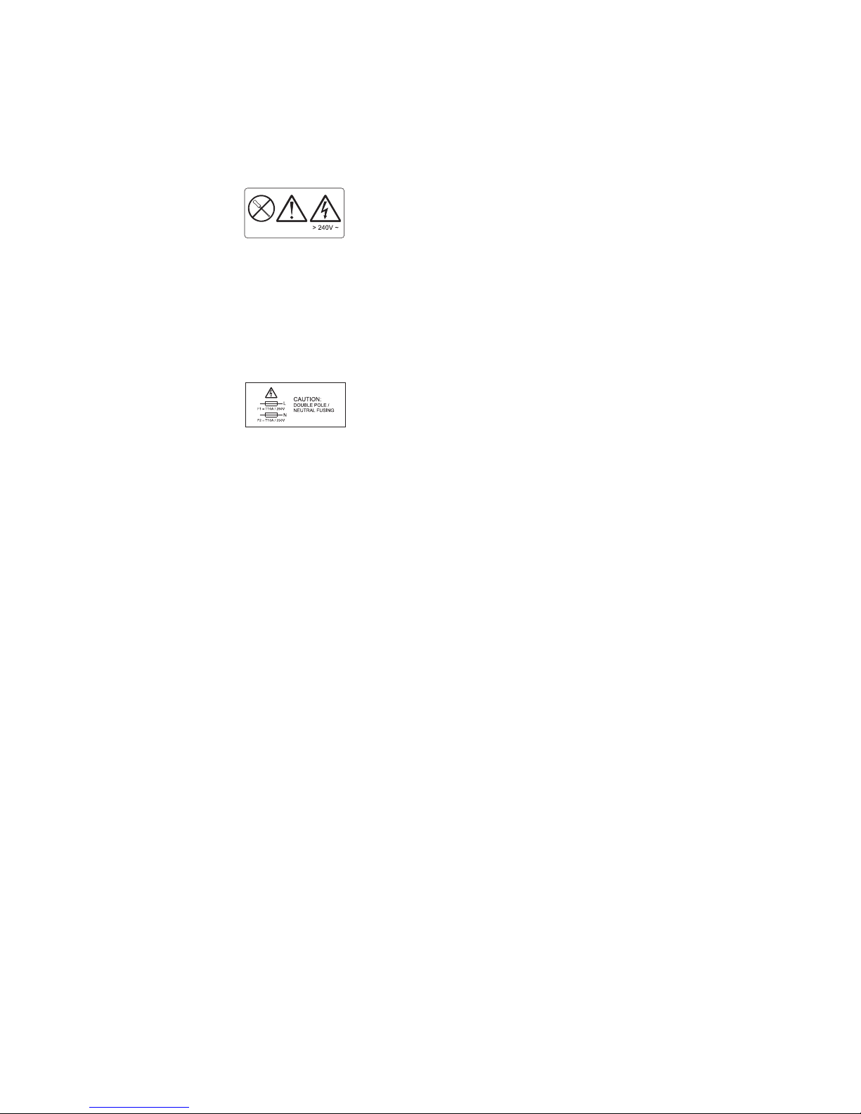
CAUTION:
Double Pole/Neutral Fusing. (3)
Figure 4. Fusing caution label
Safety and environmental notices xiii
Page 16
5. Verify that the weight label is installed on the 2104 Model DS4. See Figure 5.
CAUTION:
This unit weighs over 32 Kg (70.5 lbs). Refer to manuals. (4)
Refer to manuals 32 Kg (70.5 lbs)
SC000220
Figure 5. 2104 Model DS4 weight label
CAUTION:
If a 2104 Model DS4 is fully loaded with 14 drives and two power supplies, its
total weight exceeds 32 Kg (70.5 lbs). You must remove at least six drives from
the 2104 Model DS4 before you lift it or install it into a rack or 2104 Model TS4.
This reduces the total weight to less than 32 Kg (70.5 lbs) and the
can then be safely handled by two people. Failure to do so can result in
DS4
2104 Model
injury.
Attention:
If you have data stored on the drives, label the drives before you remove
them. When you replace the drives, install each one in the same drive bay
from which you removed it. Failure to do so could result in a loss of data.
> 18 Kg (37 lbs) > 32 Kg (70.5 lbs)
SC000334
6. Verify that the standby condition label is installed on the 2104 Model DS4. See
Figure 6.
CAUTION:
A standby condition is indicated by the symbol to the right of the DC
directly above the switch, SW1. When SW1 is toggled to the right position
directly under the standby symbol, the unit’s ac-power is not shut off. (7)
Figure 6. Standby condition label
xiv Expandable Storage Plus 2104 Model DS4 Installation Guide
Page 17
Checking the grounding of the 2104 Model DS4
Perform the following steps to check the grounding of the 2104 Model DS4:
1. Ensure that all power is removed from the rack. See the installation document
for the rack or host system.
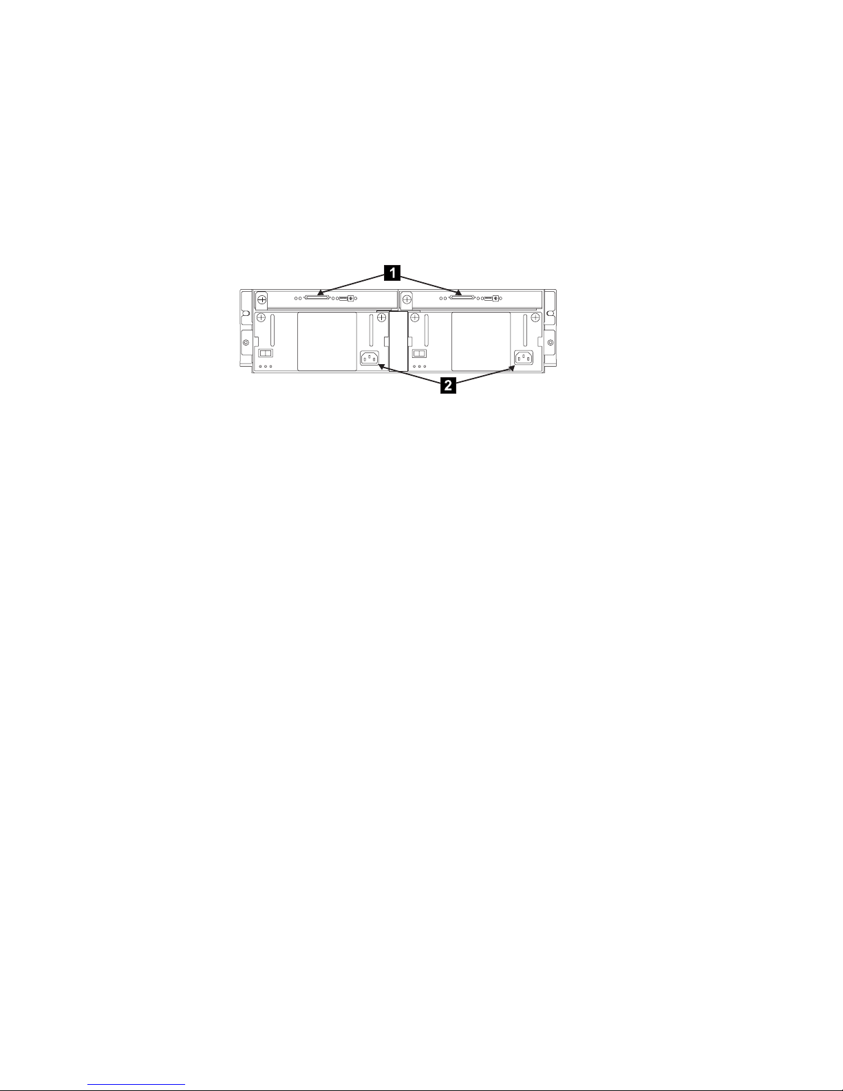
2. Ensure that the power cables 2 are plugged into each fan-and-power-supply
assembly. See Figure 7. Also ensure that the other ends of the power cables
are unplugged from the power distribution unit or battery-backup unit in the
rack. See the installation document for the rack or host system.
SC000210
Figure 7. Power cables and SCSI connectors on the 2104 Model DS4
3. Attention: Some electrical circuits could be damaged if the external SCSI
cables are connected to the 2104 Model DS4 while the grounding check is
being done.
Ensure that no external SCSI cables are plugged at the connectors 1.
4. Check the grounding of the 2104 Model DS4:
a. At the connector ends of the power plugs that you unplugged from the
power distribution unit or battery-backup unit in step 2, do a visual
inspection and ensure that the third wire ground pin is in good condition.
b. Use an ohm meter to connect one lead to the 2104 Model DS4 chassis
and the other lead to the third wire ground pin at the face of the power
connectors that you unplugged in step 2. You should read 0.1 ohm or less
between the ground pin on the power connector and the 2104 Model DS4
chassis.
Safety and environmental notices xv
Page 18
If the grounding is correct, the grounding check is complete.
If the grounding is not correct, unplug the power cables from the
fan-and-power-supply assemblies in the 2104 Model DS4.
If you are servicing a 220-volt 2104 Model DS4, go to step 5.
If you are servicing a -48 volt 2104 Model DS4, go to step 7.
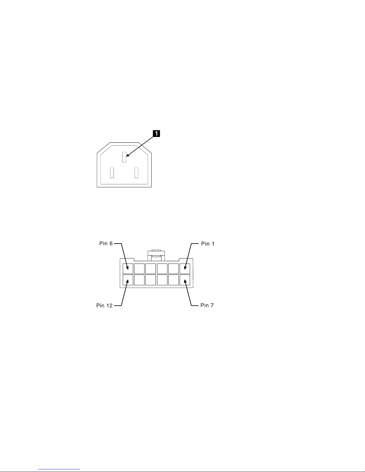
5. Check for continuity between the chassis of the 2104 Model DS4 and the
ground pin 1 of the power connector on each fan-and-power-supply
assembly. See Figure 8.
Figure 8. Ground pin (220 V 2104 Model DS4 )
6. Go to step 9.
7. Check for continuity between the chassis of the 2104 Model DS4 and the
ground pins 1 and 7 of each mainline-power connector. See Figure 9.
Figure 9. Ground pins (-48 V 2104 Model DS4)
8. Go to step 9.
9. If any fan-and-power-supply assembly has no continuity, exchange that
assembly for a new one. See the section about fan and power supply
assemblies in the Expandable Storage Plus 2104 Model DS4 and Model TS4
Service Guide. Perform the complete grounding check again.
If each fan-and-power-supply assembly has continuity, you might have a
problem with the power cable or with the grounding of the host system.
xvi Expandable Storage Plus 2104 Model DS4 Installation Guide
Page 19

If you are servicing a 220-volt 2104 Model DS4, go to step 10.
If you are servicing a -48 volt 2104 Model DS4, see the installation document
for the rack or host system to isolate the fault. Perform the complete grounding
check again.
10. Check the power cable for continuity.
If the power cable does not have continuity, exchange it for a new one, then
perform the complete grounding check again.
If the power cable does have continuity, see the installation document for the
rack or host system to isolate the fault.
Safety and environmental notices xvii
Page 20
Removing power from a 2104 Model DS4
Note: Unless you have a particular reason to do so, do not remove power from the
host system or from the 2104 Model DS4 unless the instructions that you are
following tell you to.
Perform the following steps to remove the power from a 2104 Model DS4:
1. Verify with the customer that all operations between the 2104 Model DS4 and
the host system have stopped.
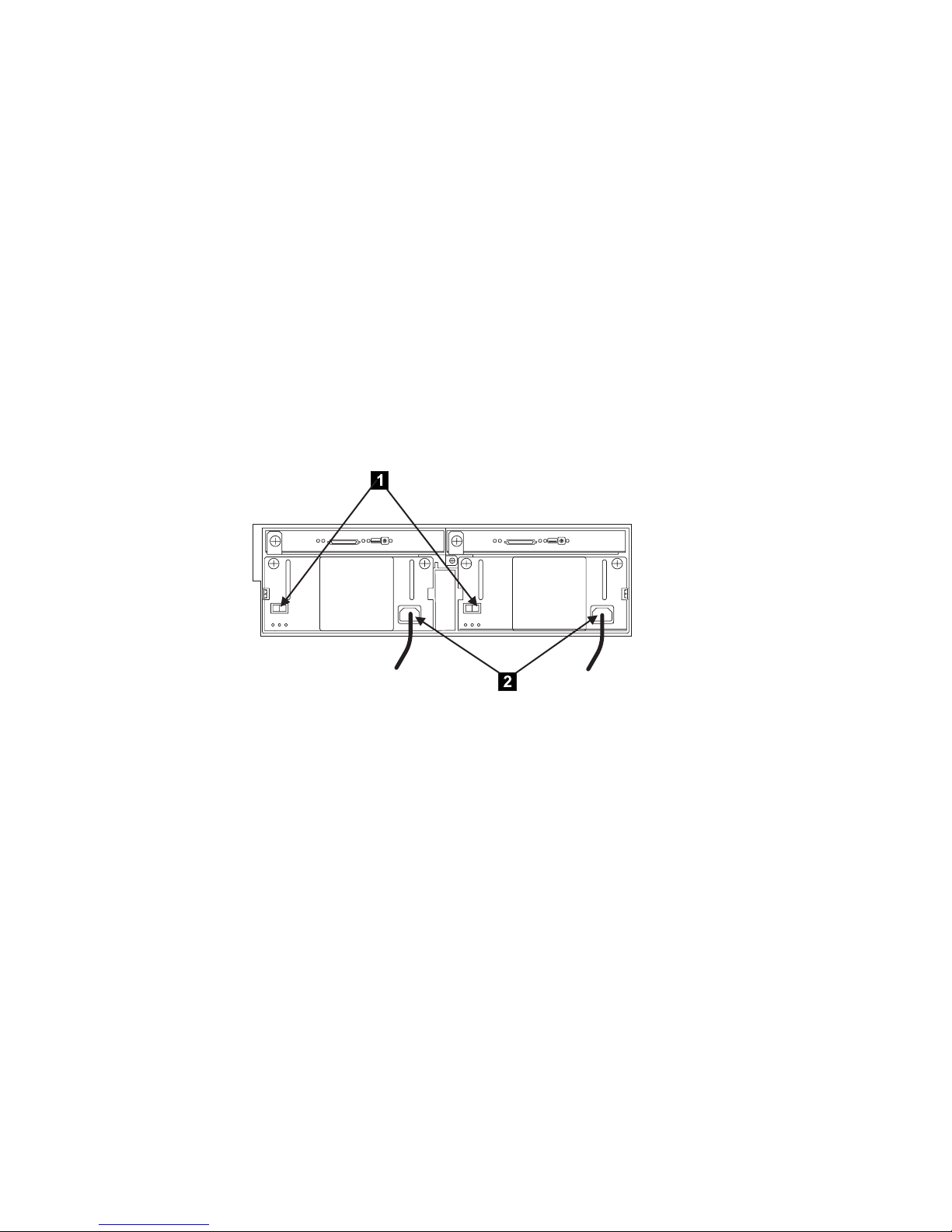
2. Set the dc on/standby switch 1 of each fan-and-power-supply assembly to
standby. See Figure 10.
Notes:
a. Some 2104 Model DS4s have a fan-and-power-supply assembly and a fan
assembly. The fan assembly has no dc on/standby switch.
b. A fan-and-power-supply assembly might have its CHK light on although its
dc on/standby switch is set to standby.
SC000206
Figure 10. Removing the power from a 2104 Model DS4
xviii Expandable Storage Plus 2104 Model DS4 Installation Guide
Page 21

3. DANGER
the following step you are going to remove the power cables. These
In
cables are live if the rack power distribution unit or uninterruptible
power supply (UPS) unit is still switched on. (1)
Remove the power cables 2 from the back of the 2104 Model DS4. See
Figure 10 on page xviii.
4. Perform the following steps to return power to the 2104 Model DS4:
a. Reinstall the power cables 2.
b. Set the dc on/standby switch 1 of each fan-and-power-supply assembly to
on.
Yo u can configure the motor-start sequencing of the 2104 Model DS4.
Note:
For more information, see the sections about the drive autostart switch
and the delay motor start mode switch in the Expandable Storage Plus
2104 Model DS4 and Model TS4 Service Guide.
Safety and environmental notices xix
Page 22
Danger notices
DANGER
the following step you are going to remove the power cables. These
In
cables are live if the rack power distribution unit or uninterruptible power
supply (UPS) unit is still switched on. (1)
DANGER
Do not try to open the covers of the fan-and-power-supply assembly. (2)
DANGER
not plug a power cable into the fan-and-power-supply assembly until
Do
the assembly is fully home and its thumbscrews are fully tightened. (3)
DANGER
electrical outlet that is not correctly wired could place hazardous
An
voltage on metal parts of the system or the devices that attach to that
system. It is the customer’s responsibility to ensure that the outlet is
correctly wired and grounded to prevent an electrical shock. During an
electrical storm, do not disconnect cables for display stations, printers,
telephones, or station protectors for communication lines. (4)
DANGER
During an electrical storm, do not disconnect cables for display stations,
printers, telephones, or station protectors for communication lines. (5)
xx Expandable Storage Plus 2104 Model DS4 Installation Guide
Page 23
Caution notices
CAUTION:
This unit might have two linecords. To remove all power, disconnect both
linecords. (1)
Figure 11. Linecord caution label
CAUTION:
Do not remove cover, do not service, no serviceable parts. (2)
Figure 12. Power supply cover caution label
CAUTION:
Double Pole/Neutral Fusing. (3)
Figure 13. Fusing caution label
Safety and environmental notices xxi
Page 24
CAUTION:
This unit weighs over 32 Kg (70.5 lbs). Refer to manuals. (4)
Refer to manuals 32 Kg (70.5 lbs)
SC000220
Figure 14. 2104 Model DS4 weight label
CAUTION:
If a 2104 Model DS4 is fully loaded with 14 drives and two power supplies, its
total weight exceeds 32 Kg (70.5 lbs). You must remove at least six drives from
the 2104 Model DS4 before you lift it or install it into a rack or 2104 Model TS4.
This reduces the total weight to less than 32 Kg (70.5 lbs) and the
can then be safely handled by two people. Failure to do so can result in
DS4
2104 Model
injury.
Attention:
If you have data stored on the drives, label the drives before you remove
them. When you replace the drives, install each one in the same drive bay
from which you removed it. Failure to do so could result in a loss of data.
> 18 Kg (37 lbs) > 32 Kg (70.5 lbs)
xxii Expandable Storage Plus 2104 Model DS4 Installation Guide
SC000334
Page 25
CAUTION:
This unit weighs between 32 Kg - 55 Kg (70.5 lbs - 121.2 lbs). (5)
32 - 55 Kg (70.5 - 121.2 lbs)
SC000219
Figure 15. 2104 Model TS4 weight label
CAUTION:
The provided cardboard lifting tool is required for moving, installing, and
relocating the product when fully populated. Three people are required to
safely move the product. Failure to do so might result in injury.
In case the lifting tool is not readily available, you must reduce the weight
to 32 Kg or less by removing all of the heavy components (disk drives
and power supplies) from the product. Then only two people are required to
move, install, and relocate the product.
(6)
Attention:
If you have data stored on the drives, label the drives before you remove them.
When you replace the drives, install each one in the same drive bay
from which you removed it. Failure to do so could result in a loss of data.
> 18 Kg (37 lbs) > 32 Kg (70.5 lbs)
SC000325
Safety and environmental notices xxiii
Page 26

CAUTION:
A standby condition is indicated by the symbol to the right of DC directly
above the switch, SW1. When you toggle SW1 to the right position directly
under the standby symbol, the ac-power to the unit is not shut off. (7)
Figure 16. Location of standby condition
CAUTION:
The stabilizer must be correctly attached to the bottom front of the rack to
prevent the rack from tipping forward while the 2104 Model DS4 is being
removed from the rack. Do not pull out or install any unit if a stabilizer is not
attached to the rack. (8)
CAUTION:
The stabilizer must be correctly attached to the bottom front of the rack to
prevent the rack from tipping forward while the 2104 Model DS4 is being
installed into the rack. Do not remove or install any unit if a stabilizer is not
attached to the rack. (9)
xxiv Expandable Storage Plus 2104 Model DS4 Installation Guide
Page 27

CAUTION:
Do not insert hands or tools into the empty space that contained the fan
assembly. (10)
CAUTION:
Do not insert hands or tools into the empty space that contained the
fan-and-power-supply assembly. (11)
CAUTION:
Do not insert hands or tools into the empty space that contained the SCSI
interface card assembly. (12)
CAUTION:
This product is equipped with a 3-wire power cable and plug for the user’s
safety. Use this power cable in conjunction with a correctly grounded
electrical outlet to avoid an electrical shock. (13)
CAUTION:
Do not touch the power outlet or the power outlet face plate with anything
other than test probes before you complete this safety check. (14)
CAUTION:
If the reading is not infinity, do not proceed. Make the necessary corrections
to the wiring before you continue. Do not switch on the branch circuit CB
until you satisfactorily complete the previous steps. (15)
CAUTION:
Do not use the handles of the fan or fan-and-power-supply assemblies to
carry the 2104 Model DS4. These handles are not intended to support the
weight of the unit. (16)
Safety and environmental notices xxv
Page 28

CAUTION:
As you push the assembly fully home, the lever automatically moves toward
its closed position. Ensure that your fingers do not become pinched between
the lever and the assembly. (17)
CAUTION:
Ensure that the mainline power cable has been removed from the failing
fan-and-power supply before you continue. (18)
CAUTION:
Do not insert hands or tools into the empty space above the fan-and-power
supply assembly. (19)
CAUTION:
Do not insert hands or tools into the empty space between the power supply
assemblies. (20)
CAUTION:
If the 2104 Model DS4 is installed in a Model T00 or T42 rack, you must also
observe the safety notices for those racks before you start to remove the
frame assembly. Yo u can find the safety notices in the section about system
installation in the 7014 Model T00 and T42 Rack Installation and Service Guide,
SA38-0577, or at the following Web site: www-
1.ibm.com/servers/eserver/pseries/library/hardware_docs/7014_t00.html
(21)
CAUTION:
The 2104 Model DS4 and Model TS4 are designed to be installed by the
customer and are certified as customer setup. Make sure that the system or
rack into which the 2104 Model DS4 or Model TS4 will be installed is also
designed and certified for customer setup. If they are not, then the 2104
Model DS4 or Model TS4 must be installed by a CE. (22)
xxvi Expandable Storage Plus 2104 Model DS4 Installation Guide
Page 29

CAUTION:
Do not insert hands or tools into the space that contained the card assembly.
(23)
CAUTION:
It takes three people to lift the 2104 Model TS4. Do not attempt to lift the 2104
Model TS4 by yourself. Do not attempt to lift it without help from two other
people. (24)
CAUTION:
Do not use the handles of the fan or fan-and-power-supply assemblies to
carry the 2104 Model TS4. These handles are not intended to support the
weight of the unit. (25)
CAUTION:
The 2104 Model DS4 is designed to be installed by the customer and is
certified as customer setup. Make sure that the system or rack into which the
2104 Model DS4 will be installed is also designed and certified for customer
setup. If they are not, then the 2104 Model DS4 must be installed by a CE. (26)
CAUTION:
The 2104 Model TS4 is designed to be installed by the customer and is
certified as customer setup. Make sure that the system into which the 2104
Model TS4 will be installed is also designed and certified for customer setup.
If it is not, then the 2104 Model TS4 must be installed by a CE. (27)
Environmental notices and statements
This section describes the environmental notices and statements.
Fire suppression systems
A fire suppression system is the responsibility of the customer. The customer’s own
insurance underwriter, local fire marshal, or a local building inspector, or both,
should be consulted in selecting a fire suppression system that provides the correct
level of coverage and protection. IBM designs and manufactures equipment to
internal and external standards that require certain environments for reliable
operation. Because IBM does not test any equipment for compatibility with fire
suppression systems, IBM does not make compatibility claims of any kind nor does
IBM provide recommendations on fire suppression systems.
Product recycling
This unit contains recyclable materials. Recycle these materials where processing
sites are available and according to local regulations. In some areas, IBM provides
a product take-back program that ensures proper handling of the product. Contact
your IBM representative for more information.
Safety and environmental notices xxvii
Page 30

xxviii Expandable Storage Plus 2104 Model DS4 Installation Guide
Page 31

About this document
This publication introduces the Expandable Storage Plus 2104 Model DS4
(hereafter referred to as the 2104 Model DS4).
Important: The installation of this product is the responsibility of the customer.
Who should read this document
This document provides installation instructions for any person who is required to
install a 2104 Model DS4, which is a rack-mounted Small Computer Systems
Interface (SCSI) disk enclosure.
Additional information
This section contains the following information:
v A list of the documents in the 2104 Model DS4 and Model TS4 library
v A list of the related documents
v The available Web sites
v Information about how to send your comments
2104 Model DS4 and Model TS4 library
The following documents contain information related to this product:
v Expandable Storage Plus 2104 Model DS4 and Model TS4 Hardware Technical
Information, SC26-7538
v Expandable Storage Plus 2104 Model DS4 and Model TS4 Operator’s Guide,
SC26-7539
v Expandable Storage Plus 2104 Model DS4 Installation Guide, GA22-1053
v Expandable Storage Plus 2104 Model TS4 Installation Guide, GA22-1054
v Expandable Storage Plus 2104 Model DS4 and Model TS4 Service Guide,
GY27-7634
v Expandable Storage Plus 2104 Model DS4 and Model TS4 Translated Safety
Notices, SC26-7558
Related documents
The following documents contain information related to this product:
v The operator’s guide for your system
v The user’s guide for your using system SCSI attachment (for example, your SCSI
adapter)
v The site and hardware planning information for your system
v The problem solving guide and reference for your system
v The 7014 Model T00 and T42 Rack Installation and Service Guide, SA38-0577
The following documents contain information related to the Expandable Storage
Plus disk enclosures that attach to the RISC systems:
v Diagnostic Information for Multiple Bus Systems, SA38-0509
v Site and Hardware Planning Information, SA38-0508
v Adapters, Devices and Cable Information for Multiple Bus Systems, SA38-0516
© Copyright IBM Corp. 2003 xxix
Page 32

Web sites
For detailed information about Expandable Storage Plus, see the following Web
site:
www-1.ibm.com/support/search.wss?rs=502&par=exclude&tc=HW28C&dc=DA400/
For a directory of worldwide contact information, including technical support, see the
following Web site:
www.ibm.com/contact/
detailed information about the adapter microcode, see the following Web site:
For
techsupport.services.ibm.com/server/mdownload/download.html/
You can find the Web support page at the following Web site:
www-1.ibm.com/support/search.wss?rs=502&par=exclude&tc=HW28C&dc=DA400/
For technical support services for the Expandable Storage Plus disk enclosures that
are attached to RISC systems, see the following Web site:
techsupport.services.ibm.com/server/support?view=pSeries/
How to send your comments
Your feedback is important to help us provide the highest quality of information. If
you have any comments about this document, you can submit them in one of the
following ways:
v E-mail
Submit your comments electronically to:
starpubs@us.ibm.com
Be sure to include the name and order number of the document and, if
applicable, the specific location of the text that you are commenting on, such as
a page number or table number.
v Mail or fax
Fill out the Readers’ Comments form (RCF) at the back of this document and
return it by mail or fax (1-800-426-6209) or give it to an IBM representative. If the
RCF has been removed, you can address your comments to:
International
RCF Processing Department
Dept. M86/Bldg. 050-3
5600 Cottle Road
San Jose, CA 95193-0001
U.S.A.
Business Machines Corporation
xxx Expandable Storage Plus 2104 Model DS4 Installation Guide
Page 33

Installing a 2104 Model DS4
The installation of this product is a customer responsibility. Before you continue with
any of the actions described in this book, see the Expandable Storage Plus 2104
Model DS4 and Model TS4 Translated Safety Notices.
This section describes how to perform the following actions:
v Install a 2104 Model DS4 into an RS/6000
(system rack or expansion rack)
v Install the switch cover plate
v Set the options
v Connect the 2104 Model DS4 to a power source
v Connect the 2104 Model DS4 to the host system
v Switch on and test the installation
The instructions assume that the following actions are complete:
v The rack is set up.
v A stabilizer is correctly attached to the bottom front of the rack to prevent the
rack from tipping forward while the 2104 Model DS4 is being installed into the
rack. If necessary, see the installation and service guide, or equivalent, for the
rack.
v You have access to:
– Preinstallation planning information for the system
– 2104 Model DS4 configuration information
™
or IBM
™
ERserver pSeries rack
If the 2104 Model DS4 is installed in the rack:
v Go to “Connecting the 2104 Model DS4 to the power source” on page 27 if the
power cables for the 2104 Model DS4 are not connected.
v Go to “Connecting the 2104 Model DS4 to the host system” on page 29 if the
power cables for the 2104 Model DS4 are connected.
Notes:
1. Each rack-mounted 2104 Model DS4 requires an airflow of 1.1 m³ per minute
(40 ft³ per minute). When racks containing many 2104 Model DS4s are to be
installed together, the following requirements must be met to ensure that the
2104 Model DS4s are adequately cooled:
v The airflow enters at the front of the rack and leaves at the back. To prevent
the air that is leaving the rack from entering the intake of another piece of
equipment, racks should be positioned in alternate rows, back-to-back and
front-to-front.
v The front of the racks should be positioned on floor-tile seams, with a full line
of perforated tiles immediately in front of the racks. Each perforated tile
should have an air flow of at least 11.34 m³ per minute (400 ft³ per minute).
The temperature under the floor must not exceed 15°C (60°F).
v Where the racks are in rows front-to-front or back-to-back, there should be a
gap of at least 1220 mm (48 in.) separating the rows.
v To ensure correct air flow within each rack, the rack filler plates must be
installed in unused positions. Also, all the gaps in the front of the racks must
be sealed, including the gaps between the 2104 Model DS4s.
2. Maintain the operating temperature at 22°C (72°F) or lower.
© Copyright IBM Corp. 2003 1
Page 34

Installing a 2104 Model DS4 into a rack
The following sections describe how to install a 2104 Model DS4 into an RS/6000
or IBM Eserver pSeries rack.
Checking the items for a 2104 Model DS4
Ensure that you have received all the parts required for your 2104 Model DS4. See
Figure 17.
Note: If your 2104 Model DS4 has only one fan-and-power-supply assembly, only
one power cable is supplied.
1
8
1
2104 Model DS4
2
Mounting screws (front)
3
Rail mounting screws
4
Nut clips
5
Support rails
6
Mounting screws (back)
7
Power cable(s)
8
Box ID label
SC000205
Figure 17. Items for the 2104 Model DS4
1. The box ID label 8 contains small labels. Use these to label your disk
enclosure. See step 3 on page 19.
2. Refer to “Web sites” on page xxx for the latest microcode and system software
levels. When you complete the installation, you will be asked to ensure that the
latest levels of software and microcode are installed.
2 Expandable Storage Plus 2104 Model DS4 Installation Guide
Page 35

Preparing the rack (system or expansion)
Perform the following steps to prepare the rack (system or expansion):
1. Find the two support rails 5 that are supplied with the 2104 Model DS4. See
Figure 17 on page 2.
2. The 2104 Model DS4 is three Electronics Industries Association (EIA) units high.
Using the preinstallation planning information, or other relevant information,
determine where you are going to locate the 2104 Model DS4 in the rack.
Notes:
a. If you are installing the 2104 Model DS4 into an empty rack, install it into the
lowest available position so that the rack does not become unstable.
b. If you are installing more than one 2104 Model DS4 into the rack, start at
the lowest available position, and work upward.
c. You might need to remove the power distribution unit before you install the
support rails. See the installation and service guide, or equivalent, for the
rack.
Refer to the EIA markings on the rack and decide where you are going to install
3.
the support rails. If appropriate, allow for possible future installation of other disk
enclosures.
4. Perform the following steps for each support rail:
a. Attach the nut clips 2 at the selected holes in the front of the rack. See
Figure 18. These nut clips must align with the upper and lower holes in the
support rail.
3
1
2
5
Figure 18. Installing the support rails
6
4
4
SC000922
Installing a 2104 Model DS4 3
Page 36

b. Count two holes upward from the upper nut clip, and attach a nut clip 1.
c. At the back of the rack, install the two nut clips 3 at the selected holes.
d. Loosen the four adjustment screws 4 so that you can adjust the length of
the support rail.
e. At the front of the rack, locate the support rail so that its mounting lug is
outside the nut clips 2.
f. Insert the rail screws 5 through the holes in the lug and into the nut clips.
g. Partially tighten the screws.
h. At the back of the rack, locate the support rail so that its mounting lug is
outside the nut clips 3.
i. Insert the rail screws 6 through the holes in the lug and into the nut clips.
j. Partially tighten the screws.
k. Check whether the support rail is horizontal (a spirit level might be useful
here). If the rail is not horizontal, position it as necessary.
l. Fully tighten the front and back rail screws.
m. Fully tighten the four adjustment screws 4.
Go to “Removing the disk drive modules and dummy disk drive modules” on
5.
page 5.
4 Expandable Storage Plus 2104 Model DS4 Installation Guide
Page 37

Removing the disk drive modules and dummy disk drive modules
CAUTION:
This unit weighs over 32 Kg (70.5 lbs). Refer to manuals. (4)
Refer to manuals 32 Kg (70.5 lbs)
SC000220
Figure 19. 2104 Model DS4 weight label
CAUTION:
If a 2104 Model DS4 is fully loaded with 14 drives and two power supplies, its
total weight exceeds 32 Kg (70.5 lbs). You must remove at least six drives from
the 2104 Model DS4 before you lift it or install it into a rack or 2104 Model TS4.
This reduces the total weight to less than 32 Kg (70.5 lbs) and the
can then be safely handled by two people. Failure to do so can result in
DS4
injury.
2104 Model
Attention:
If you have data stored on the drives, label the drives before you remove
them. When you replace the drives, install each one in the same drive bay
from which you removed it. Failure to do so could result in a loss of data.
> 18 Kg (37 lbs) > 32 Kg (70.5 lbs)
SC000334
Installing a 2104 Model DS4 5
Page 38

Attention: Disk drive modules are fragile. Handle them with care, and keep them
well away from strong magnetic fields.
Perform the following steps to remove the disk drive modules and the dummy disk
drive modules:
1. Before you start to remove any modules, make a list of which disk drive
modules are in which slots in the 2104 Model DS4. This action helps you to
reinstall the modules into their correct slots after you have installed the 2104
Model DS4 into the rack.
Disk drive modules have a serial number label 1. Figure 20 shows the label
on the 2104 Model DS4. This label carries the last 8 to 10 digits of the serial
number of the disk drive, and also the disk drive type (SCSI) and capacity (for
example, 36.4 GB).
Each disk drive module also has a SCSI address that is related to its
Note:
position in the 2104 Model DS4. You must reinstall the disk drive
modules into the same slots from which they were removed.
IBM 36.4 GB 10K
U320 S/N AK0B5863
Figure 20. Disk drive modules that show the position of the 2104 Model DS4 serial number
label
6 Expandable Storage Plus 2104 Model DS4 Installation Guide
SC000359
Page 39

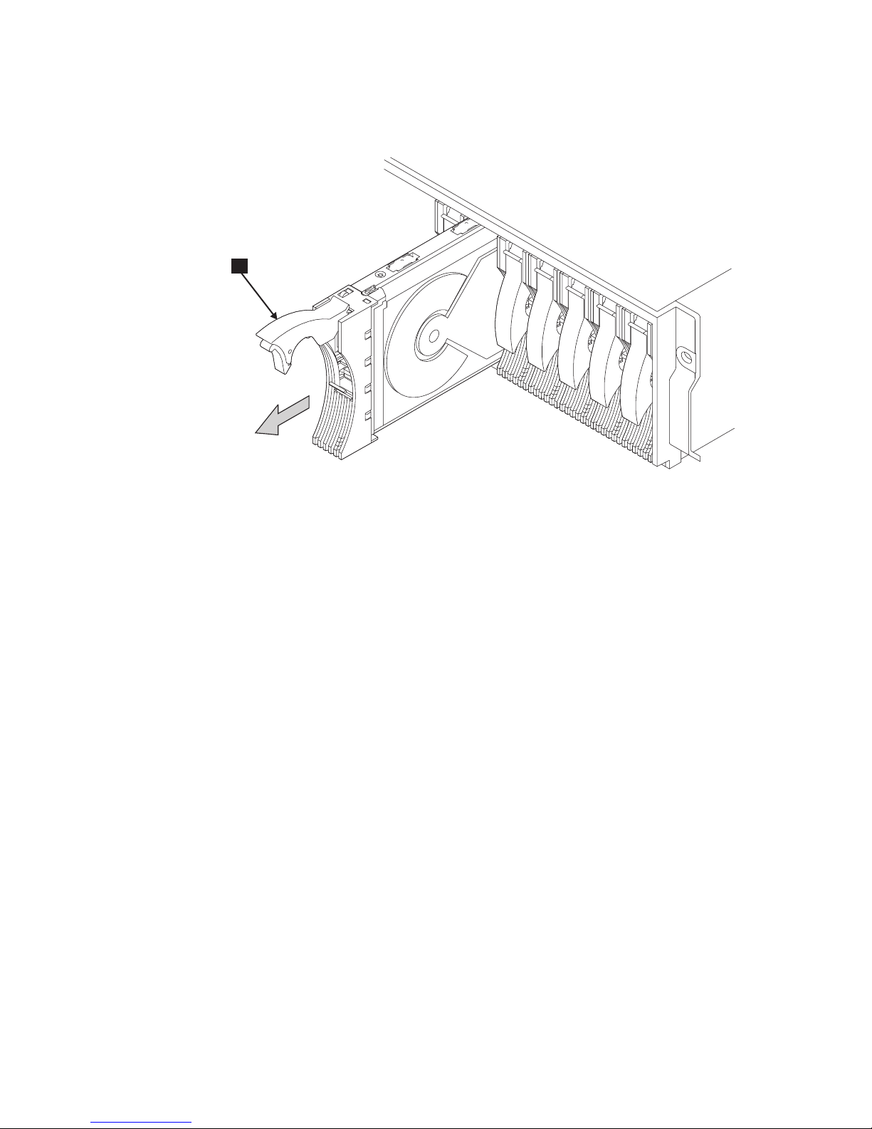
2. Press the blue latch 1, and pull the handle 2 fully up. See Figure 21. This
action pulls the disk drive module partially out of its slot.
Figure 21. Opening the handle of a disk drive module
SC000923
Installing a 2104 Model DS4 7
Page 40
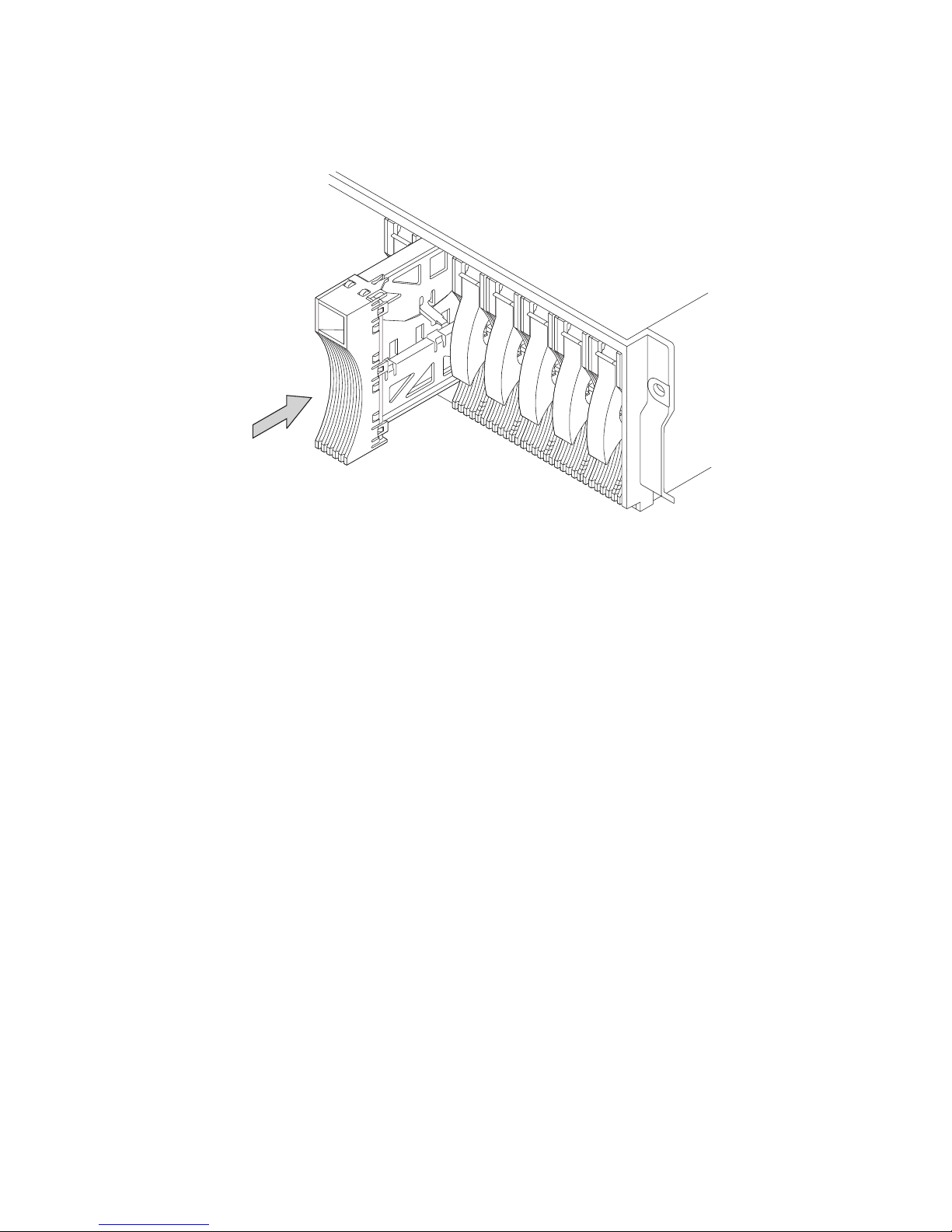
3. Grip the handle 1, and carefully pull the disk drive module. See Figure 22. As
the module comes out, put one hand under its base to prevent it from falling.
1
Figure 22. Removing a disk drive module
SC000317
8 Expandable Storage Plus 2104 Model DS4 Installation Guide
Page 41

4. Lay the disk drive module on its side. See Figure 23. It rests on blue supports
(not visible in the figure) on the bottom of the disk drive module. This prevents
the disk drive module from falling over and becoming damaged.
SC000924
Figure 23. Disk drive module on its side for safe storage
Note: Keep the removed disk drive modules in the sequence they were in before
you removed them from the 2104 Model DS4.
5. Repeat step 2 through step 4 for each disk drive module. Ensure that you
remove all the disk drive modules from the 2104 Model DS4.
Installing a 2104 Model DS4 9
Page 42

6. You might also want to remove the dummy disk drive modules. See Figure 24. A
dummy disk drive module has a simple handle. There is no latch to pull up.
Figure 24. Removing a dummy disk drive module
SC000925
10 Expandable Storage Plus 2104 Model DS4 Installation Guide
Page 43

Installing the 2104 Model DS4 into the rack
CAUTION:
This unit weighs over 32 Kg (70.5 lbs). Refer to manuals. (4)
Refer to manuals 32 Kg (70.5 lbs)
SC000220
Figure 25. 2104 Model DS4 weight label
CAUTION:
If a 2104 Model DS4 is fully loaded with 14 drives and two power supplies, its
total weight exceeds 32 Kg (70.5 lbs). You must remove at least six drives from
the 2104 Model DS4 before you lift it or install it into a rack or 2104 Model TS4.
This reduces the total weight to less than 32 Kg (70.5 lbs) and the
can then be safely handled by two people. Failure to do so can result in
DS4
injury.
2104 Model
Attention:
If you have data stored on the drives, label the drives before you remove
them. When you replace the drives, install each one in the same drive bay
from which you removed it. Failure to do so could result in a loss of data.
> 18 Kg (37 lbs) > 32 Kg (70.5 lbs)
CAUTION:
SC000334
Do not use the handles of the fan or fan-and-power-supply assemblies to
carry the 2104 Model DS4. These handles are not intended to support the
weight of the unit. (16)
Installing a 2104 Model DS4 11
Page 44

CAUTION:
The stabilizer must be correctly attached to the bottom front of the rack to
prevent the rack from tipping forward while the 2104 Model DS4 is being
installed into the rack. Do not remove or install any unit if a stabilizer is not
attached to the rack. (9)
If you are going to install the 2104 Model DS4 into a Model T00 or T42 rack,
Note:
you must also observe the safety notices for those racks before you start.
You can find the safety notices in the system installation chapter of the 7014
Model T00 and T42 Rack Installation and Service Guide, SA38-0577, or at
the following Web site:
www-1.ibm.com/servers/eserver/pseries/library/
hardware_docs/sa38/380577.pdf
Perform the following steps to install the 2104 Model DS4 into the rack:
1. If you have not already done so, remove all of the disk drive modules from the
2104 Model DS4. For more information, see “Removing the disk drive modules
and dummy disk drive modules” on page 5.
2. Stand at the front of the rack. With help from another person, place the back of
the 2104 Model DS4 onto the support rails. Slide the 2104 Model DS4 into the
rack.
3. Install the two front mounting screws 1 and tighten them. See Figure 26.
Figure 26. Installing the front mounting screws
12 Expandable Storage Plus 2104 Model DS4 Installation Guide
SC000284
Page 45

4. At the back of the rack, install and tighten the two screws 1. See Figure 27.
These are the screws identified as 6 in Figure 17 on page 2.
Note:
SC000192
Figure 27. Installing the back mounting screws
5. Go to “Reinstalling the disk drive modules and dummy disk drive modules” on
page 14.
Installing a 2104 Model DS4 13
Page 46

Reinstalling the disk drive modules and dummy disk drive modules
Attention:
v Disk drive modules are fragile. Handle them with care, and keep them well away
from strong magnetic fields.
v Any slot that has no disk drive module installed must contain a dummy disk drive
module. The dummy disk drive module ensures that the correct airflow is
maintained around the disk drive modules in the other slots.
Perform
the following steps to reinstall the disk drive modules in the same
sequence that you removed them:
1. Refer to the note that you made about the original locations of the disk drive
modules.
2. Ensure that the handle 1 is fully open on the disk drive module that you are
going to install. See Figure 28.
IBM 36.4 GB 10K
U320 S/N AK0B5863
Figure 28. Reinstalling a 2104 Model DS4 disk drive module
3. With one hand giving support to the base of the disk drive module and the other
hand holding the handle 1, insert the disk drive module and push it into the
slot.
When the handle touches the front surface of the enclosure, the module stops.
The disk drive module is not yet fully home.
14 Expandable Storage Plus 2104 Model DS4 Installation Guide
SC000358
Page 47

4. While you continue to push the disk drive module into the slot, slowly close the
handle 1 until it stops with a click. See Figure 29. This action pushes the
module fully home.
SC000926
Figure 29. Closing the handle of a disk drive module
5. Verify that the disk drive module that you have just installed is aligned with the
sides of the 2104 Model DS4 and that no gap exists between this module and
the modules that are next to it.
Verify also that the front edge of this disk drive module aligns with the front
edges of the modules that are next to it.
If the disk drive module is not correctly aligned, remove it (see “Removing the
disk drive modules and dummy disk drive modules” on page 5). Repeat step 1
on page 14 through step 4 to reinstall the disk drive module.
6. Repeat step 1 through step 5 for each disk drive module.
Attention: Any slot that has no disk drive module installed must contain a
dummy disk drive module. The dummy disk drive module ensures that the
correct airflow is maintained around the disk drive modules in the other slots.
Installing a 2104 Model DS4 15
Page 48
7. Ensure that the 2104 Model DS4 has no empty slots. Install dummy disk drive
modules if necessary. See Figure 30.
Figure 30. Reinstalling a dummy disk drive module
8. Go to “Installing the switch cover plate” on page 17.
SC000927
16 Expandable Storage Plus 2104 Model DS4 Installation Guide
Page 49

Installing the switch cover plate
Note: Switch configuration is only valid on the SCSI interface card-1, which is on
the left side (left side from the rear view). The configuration on the SCSI
interface card-2, which is on the right side, is ignored. The switch cover plate
is on card-2 so that it can be masked. See Figure 31. Yo u must place the
SCSI interface card in the left side from the rear view in a single SCSI
interface card configuration. See JBOD 1 in Figure 31.
OPTION
SWITCH
54321
SW Cover added on 2nd JBOD card
JBOD 1
UNITID
OPTION
SWITCH
0
1
9
2
8
3
7
4
6
5
54321
UNIT ID
0
1
9
8
7
6
5
Switch Cover plate
4
2
3
CAR
CARD
JBOD 2
SC000277
Figure 31. Installing the switch cover plate onto the panel of the SCSI Interface card-2
(second JBOD interface card) box
Perform the following steps to install the switch cover plate onto the panel of the
SCSI Interface card-2 (second JBOD interface card).
Note: If the switch cover plate is already installed, you do not need to perform step
1 through step 3 on page 18.
1. Locate the hook, latch, and pins. See Figure 32 on page 18.
Installing a 2104 Model DS4 17
Page 50

Guide Pin
Hook
Latch
OPTION
SWITCH
54321
UNIT ID
9
8
7
6
CAR
0
1
2
3
4
5
CARD
SC000275
Figure 32. Inside the switch cover plate showing the hook, latch, and two guide pins with the
SCSI Interface card assembly
2. Align the plate to the holes.
3. Plug and slide to the left until plate is latched.
4. Go to “Setting the options” on page 19.
18 Expandable Storage Plus 2104 Model DS4 Installation Guide
Page 51

Setting the options
Perform the following steps to set the options on the 2104 Model DS4:
1. Refer to your 2104 Model DS4 configuration information for details to set the
2. Use a small screwdriver to rotate the Box ID rotary switch (see Figure 33) to
options.
the ID you have chosen for this 2104 Model DS4 disk enclosure.
SC000015
Figure 33. Setting the box ID
3. Find the sheet of labels supplied with your 2104 Model DS4. These are
numbered 0 through 9. Select the one that represents your setting of the Box
ID rotary switch. Attach it to the front of the 2104 Model DS4.
Note: When running the Linux operating system, you can set the Box ID
switch and attach the Box ID label. Your Linux operating system might
or might not display the Box ID in its system messages.
The Box ID is used when running the standalone AIX Diagnostics CD.
Note:
Installing a 2104 Model DS4 19
Page 52

4. Figure 34 shows the option switches. When the drive autostart switch-1 1 is
set to off, and the drive autostart switch-2 2 is set to on, the disk drive
motors do not start until you issue a START MOTOR command. The timing
sequence of disk motor startup is under the control of the host system
software.
SC000011
Figure 34. Setting the option switches
When the drive autostart switch-1 1 is set to on and the drive autostart
switch-2 2 is set to off, the disk drives are set to delay motor start mode. The
disk motor startup delay time is different for each disk drive, and is usually
computed by multiplying its SCSI ID by 12 seconds. For example, the disk
drive motor of a disk drive with a SCSI ID equal to 2 will start 24 ( 2 x 12)
seconds after power is applied to the 2104 Model DS4.
When the drive autostart switch-1 1 is set to off, and the drive autostart
switch-2 2 is set to off, the disk drives are set to normal start mode. The disk
drive motors will start when power is applied to the 2104 Model DS4.
The effect of both this switch and the drive autostart switch-2 2 being set to
on is undefined.
5. To set the drive autostart switch-2 2, see step 4 for an explanation about the
drive autostart switch-1 1.
6. Ensure that the enable enclosure services switch 3 and the select enclosure
services switch 4 are both set to on to allow ANSI SCSI-3 Enclosure
Services (SES) to operate. This applies to both AIX and Linux users. Your
Linux operating system might not support SES, but the SES functions are used
when running the standalone AIX Diagnostics CD.
7. When the power control switch 5 is set to off, the 2104 Model DS4
automatically switches off or on when the host system is switched off or on.
When this switch is set to on, the 2104 Model DS4 is powered on or off by the
dc on/standby switch on a fan-and-power-supply assembly.
20 Expandable Storage Plus 2104 Model DS4 Installation Guide
Page 53

8. Remove the card assembly. Check and, if necessary, change the settings of
the internal switches of SCSI interface card-1 (left side from the rear view).
You do not need to set internal switches of SCSI interface card-2 (right side)
because they are ignored.
a. Unscrew the thumbscrew 1. See Figure 35.
Figure 35. Unscrewing the thumbscrew
SC000357
Installing a 2104 Model DS4 21
Page 54

b. Pull the lever 1 out to unplug the card assembly from the 2104 Model
DS4. See Figure 36.
Figure 36. Opening the lever on the card assembly
SC000356
22 Expandable Storage Plus 2104 Model DS4 Installation Guide
Page 55
c. CAUTION:
Do not insert hands or tools into the space that contained the card
assembly. (23)
Pull the card assembly out from the 2104 Model DS4. See Figure 37.
Figure 37. Removing the card assembly
SC000355
Installing a 2104 Model DS4 23
Page 56

9. Figure 38 shows other switches on the SCSI interface card.
11
12
13
15
16
17
18
14
7
8
9
10
SC000208
Figure 38. Card assembly switches
10. The SCSI bus split control 7 controls the SCSI bus mode. When the switch
is off, the enclosure is configured as a single SCSI bus. When this switch is
on, the enclosure is configured as a dual or split SCSI bus.
11. Verify that switch 8 and 9 (reserved) are off.
12. Verify that the disable ID 6 handling switch 10 is off. The SCSI ID 6 is
automatically disabled and removed from the system when the following
conditions are met:
v The switch is off.
v Two SCSI interface cards are installed with single-bus configuration.
v Two hosts are connected to the 2104 Model DS4 and both are on.
When you install two SCSI Interface cards and you configure the 2104 Model
DS4 for single-bus mode, an ID conflict occurs if you install a drive in the slot
of SCSI ID 6. The ID conflict exists because one of the host bus adapter
(HBA) SCSI IDs should be set to 6 when using both host ports. Unless the
disable ID 6 handling switch is off or the drive is removed from the slot of
SCSI ID 6, there will be an ID conflict between the HBA that is using ID 6 and
the drive in the slot of SCSI ID 6. Removing the drive from slot 6 and replacing
it with a dummy carrier eliminates the conflict.
An alternative is to turn the disable ID 6 handling switch off, which
continuously applies a SCSI RESET signal to the drive in the slot of ID 6 when
TERMPWR is present on both JBOD interface cards. While the drive is held in
RESET, it releases all bus signals, effectively removing it from the system. The
drive in the slot of SCSI ID 6 will continuously remain in RESET under these
conditions until power is removed and the disable SCSI ID 6 handling switch is
on.
24 Expandable Storage Plus 2104 Model DS4 Installation Guide
Page 57

13. The configuration switch 11 – 18 must always be set to off in the 2104
Model DS4. See Figure 38 on page 24.
14. Reinstall the card assembly.
a. CAUTION:
As you push the assembly fully home, the lever automatically moves
toward its closed position. Ensure that your fingers do not become
pinched between the lever and the assembly. (17)
Insert the card assembly into the 2104 Model DS4. See Figure 39. Push
the assembly in until it stops.
Figure 39. Inserting the card assembly
SC000354
Installing a 2104 Model DS4 25
Page 58

b. Push the lever 1 until it is fully closed to plug the card assembly into the
2104 Model DS4. See Figure 40.
c. Tighten the thumbscrew 1 fully.
SC000353
Figure 40. Closing the lever on the card assembly
15. Go to “Connecting the 2104 Model DS4 to the power source” on page 27.
26 Expandable Storage Plus 2104 Model DS4 Installation Guide
Page 59

Connecting the 2104 Model DS4 to the power source
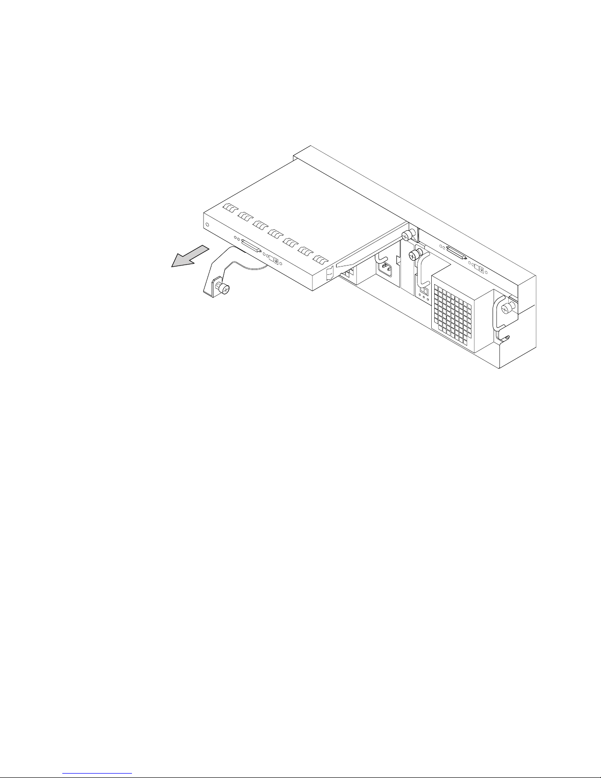
Perform the following steps to connect the 2104 Model DS4 to the power source:
1. Attention: Never use power cables from another drawer to connect a 2104
Model DS4 to the mainline power outlet. Use only the shielded power cables
that are supplied with the 2104 Model DS4.
At the back of the 2104 Model DS4, plug a power cable into the mainline power
connector 1 on each fan-and-power-supply assembly. See Figure 41.
Figure 41. Connecting the power plugs
SC000352
Installing a 2104 Model DS4 27
Page 60

2. Ensure that the dc on/standby switch 1 is set to standby. See Figure 42.
SC000351
Figure 42. Checking the power supply switch and lights
3. Ensure that all power is removed from the rack.
4. Plug the other end of the power cable into the power source in the rack (see the
installation and service guide, or equivalent, for the rack).
5. Perform the grounding checks described in the Expandable Storage Plus: 2104
Model DS4 and Model TS4 Service Guide.
6. If the grounding check is satisfactory, turn the power on to the rack. The green
AC PWR light 4 comes on.
7. Switch on the dc on/standby switch 1 on each power supply. If option switch
5 (see Figure 34 on page 20) is on, the green DC PWR light 3 comes on
and the check light 2 becomes off. See Figure 42. If option switch 5 (see
Figure 34 on page 20) is off, the green DC PWR light 3 (see Figure 42) stays
off and the check light 2 stays on. It will come on when the 2104 Model DS4
is connected to the host system.
8. Go to “Connecting the 2104 Model DS4 to the host system” on page 29.
28 Expandable Storage Plus 2104 Model DS4 Installation Guide
Page 61

Connecting the 2104 Model DS4 to the host system
Perform the following steps to connect the 2104 Model DS4 to the host system:
1. Refer to the 2104 Model DS4 configuration information and check how the 2104
Model DS4 is to be connected to the host system. Go to “Valid configurations”
on page 35 to verify your configuration.
2. Attach identification labels to the external SCSI signal cables. For details, see
the appropriate adapters, devices, and cables information manual.
3. Plug the SCSI signal cables into the connectors 1 on the SCSI interface
cards. See Figure 43.
SC000003
Figure 43. Plug in the SCSI signal cable
4. Attention: Do not use a power-driven screwdriver.
Tighten the retaining screws 2. Yo u might need a small screwdriver to do this.
Installing a 2104 Model DS4 29
Page 62

5. Ensure that all signal cables are correctly connected. See Figure 44. An
incorrect connection can prevent the 2104 Model DS4 from becoming ready.
SC000286
Figure 44. Back of fully configured 2104 Model DS4 after connection to the host system
30 Expandable Storage Plus 2104 Model DS4 Installation Guide
Page 63

Switching on and testing the 2104 Model DS4
Perform the following steps to switch on and test the 2104 Model DS4:
1. If the power to the host system is switched off, switch it on.
2. Refer to Figure 45.
1
2
3
4
5
SC000285
Figure 45. Checking the lights
The 2104 Model DS4 has three lights. The green power light 1 comes on and
stays on. The amber check light 2 comes on for approximately 2 seconds and
goes off. The unit identity light 3 is off. See Figure 45.
Each disk drive module has two lights. The green activity light 4 comes on for
approximately 2 seconds when power is first supplied to the disk drive; it then
goes off. The amber check light 5 then comes on for approximately 2 seconds
and then goes off.
Dummy disk drive modules have no lights.
Note:
Configuration is complete when the lights on the 2104 Model DS4 and its
installed disk drive modules are as follows:
2104 Model DS4 power light 1 is on.
2104 Model DS4 check light 2 is off.
2104 Model DS4 unit identify light 3 is off.
Activity light 4 on each installed disk drive module is off.
Check light 5 on each installed disk drive module is off
If the lights are correct:
a. Refer to “Web sites” on page xxx for the latest microcode and system
software levels. Ensure that the using system software is at the correct level
for the 2104 Model DS4, and that the correct level of microcode for the disk
drive modules has been loaded.
b. Go to Appendix B, “Cable configurations,” on page 35, which gives
information about how to configure your 2104 Model DS4 to the host
Installing a 2104 Model DS4 31
Page 64

system, what service aids are available, and how to collect statistics during
the operation of your 2104 Model DS4.
If the lights are not as described here, refer to the Expandable Storage Plus:
2104 Model DS4 and Model TS4 Service Guide for help in identifying the cause
of this fault.
32 Expandable Storage Plus 2104 Model DS4 Installation Guide
Page 65

Appendix A. Operating with RISC systems
This appendix describes how to operate an RS/6000 or IBM ERserver pSeries
computer to which one or more 2104 Model DS4s are attached.
System service aids
Service aids are available on the host system to help you service the 2104 Model
DS4. The following service aids are described in the Expandable Storage Plus 2104
Model DS4 and Model TS4 Service Guide:
v Format Media
v Certify Media
v SCSI Device Identification and Removal
v Download Microcode
Identifying a 2104 Model DS4 and the disk drive modules
You can identify a 2104 Model DS4 and the disk drive modules installed in it by
running either AIX or Linux.
Refer to the 2104 Interoperability Matrix link located at the following Web site
Note:
to learn which versions of AIX or Linux are supported for the Expandable
Storage Plus family of products.
www.storage.ibm.com/disk/expplus/supserver.htm/
AIX
When running AIX, you can identify an 2104 Model DS4 and the disk drive modules
installed in it either by the location code contained in system messages that refer to
that unit, or by using the SCSI Device Identification and Removal service aid.
For more information, see the section about location codes in the operator guide for
your system.
Linux
When running Linux, you can identify an 2104 Model DS4 and the disk drive
modules installed in it by using the List Configuration command. Consult your
Linux operating system documentation for information on how to use this command.
Configuring a 2104 Model DS4 to an AIX host system
Use the cfgmgr command to configure or reconfigure a 2104 Model DS4 to the
host system.
This command might not be valid for your RAID adapter.
Note:
Unconfiguring a 2104 Model DS4 from an AIX host system
To remove a 2104 Model DS4 from the host system, use the following command:
rmdev -l [enclosurenumber] -d
© Copyright IBM Corp. 2003 33
Page 66

where [enclosurenumber] is the enclosure device that was generated by the cfgmgr
command (for example, [ses0], [ses1], [ses2]).
Remove the ses_healthcheck job from the system cron table.
Configuring a 2104 Model DS4 in a SuSE Enterprise Server for pSeries
environment
In general, SuSE Enterprise Server for pSeries systems are automatically
configured during initial start up or restart up. See the SuSE Enterprise Server for
pSeries documentation for more information.
Collecting Errors
Note: Collecting errors through the cron job is only available on systems that are
running AIX.
To collect enclosure errors, add this cron job SES Healthcheck to the system cron
table.
Note: Yo u must have root permissions to complete this procedure.
the system crons with the crontab -e command. At the bottom of the file, enter:
Edit
15 * * * * /usr/lpp/diagnostics/bin/run_ses_healthcheck 1> /dev/null 2>
/dev/null
For more information about the crontab command, see the following Web page:
http://publib16.boulder.ibm.com/pseries/en_US/cmds/aixcmds1/crontab.htm
This cron runs at 15 minutes after each hour, and e-mails the root user with details
of any errors in the enclosure. It also presents a console message that indicates
which enclosure has a problem. The cron requires a script. To create this script,
generate a file named run_ses_healthcheck in the /usr/lpp/diagnostics/bin directory.
The contents of the file must be:
#!/bin/ksh
#Name: run_ses_healthcheck
#Location: /usr/lpp/diagnostics/bin
#Function: SCSI SES hourly healthcheck
for i in `lsdev -Cc container -t ses -s scsi -F name -S available`
do
diag -cd $i > /dev/null
if [ $? -ne 0 ]
then
done
/usr/lpp/diagnostics/bin/diagrpt -o > /tmp/ses.health.output
# you may want to process the output prior to placing it in
# a file.
# somehow notify the user of the error. A sample is shown
# below.
mail -s ’2104 Health Check’ root < /tmp/ses.health.output
rm /tmp/ses.health.output
fi
This command runs the script:
chmod 544 /usr/lpp/diagnostics/bin/run_ses_healthcheck
34 Expandable Storage Plus 2104 Model DS4 Installation Guide
Page 67

Appendix B. Cable configurations
This appendix shows examples of cable configurations for the 2104 Model DS4.
Some of the configurations are valid for all the adapters that the 2104 Model DS4
or Model TS4 supports. Other configurations are valid only for particular types of
adapters. Also shown are configurations that are invalid. Do not use any
configuration that is shown as invalid; unexpected results might occur.
Valid configurations
Only point-to-point connections are allowed between the SCSI interface cards in a
2104 Model DS4 and the SCSI adapter card or integrated SCSI port in a host
system.
A 2104 Model DS4 with only one SCSI interface card can be attached to one SCSI
adapter or integrated SCSI port. A 2104 Model DS4 with two SCSI interface cards
can be attached to two SCSI adapters or integrated SCSI ports.
When you use an internal connector on the adapter card, do not use the
corresponding external connector to connect to a 2104 Model DS4.
A 2104 Model DS4 can be configured to support either a single SCSI bus or a dual
SCSI bus. The setting of the SCSI bus split switch on the card in the 2104 Model
DS4 defines which configuration is to be used.
An RS/6000 or IBM Eserver pSeries computer uses one of the following SCSI
adapters to connect to the 2104 Model DS4:
v PCI Dual-Channel Ultra3 SCSI adapter (type number 4-Y, feature code 6203)
This dual-channel adapter has two external SCSI connectors and two internal
SCSI connectors. Each pair, consisting of one external and one internal
connector, is connected to a separate SCSI channel.
v PCI 4-Channel Ultra3 SCSI RAID Adapter (type number 4-X, feature code 2498)
This 4-channel adapter has four external SCSI connectors and two internal SCSI
connectors. The Channel 1 and Channel 2 external connectors share the same
SCSI bus as the corresponding Channel 1 and Channel 2 internal connectors.
The Channel 3 and Channel 4 external connectors have their own non-shared
SCSI bus.
v PCI-X Dual Channel Ultra320 SCSI adapter (type number 5702, feature code
5712)
This dual-channel adapter has two external SCSI connectors and two internal
SCSI connectors. Each pair, consisting of one external and one internal
connector, is connected to a separate SCSI channel.
v PCI-X Dual Channel Ultra320 SCSI RAID Adapter (type number 5703, feature
code 5703)
This dual channel adapter has two Ultra320 SCSI busses, each with one internal
and one external connector.
© Copyright IBM Corp. 2003 35
Page 68

An IBM Eserver pSeries computer running Linux on pSeries uses one of the
following SCSI adapters to connect to the 2104 Model DS4:
v PCI-X Dual Channel Ultra320 SCSI Adapter (type number 5702, feature code
5712)
v PCI-X Dual Channel Ultra320 SCSI RAID Adapter (type number 5703, feature
code 5703)
v PCI Dual-Channel Ultra3 SCSI Adapter (type number 4-Y, feature code 6203)
36 Expandable Storage Plus 2104 Model DS4 Installation Guide
Page 69

Summary of valid configurations
Table 1 shows a summary of valid configurations and SCSI ID assignments.
Table 1. Valid configurations
SCSI bus
mode
Single bus 1 7 14 0, 1, 2, 3, 4, 5, 6, 8,
Single bus 2 5, 6 12 0, 1, 2, 3, 4, 8, 9,
Dual bus SCSI
bus 1
Dual bus SCSI
bus 2
Number of
connected
adapters
SCSI IDs
of
adapters
Maximum
number of
disk drive
SCSI IDs of disk
drive modules
modules
9, 10, 11, 12, 13, 14
10, 11, 12, 13, 14
1 7 7 0, 1, 2, 3, 4, 5, 6
See Note 3.
1 7 7 8, 9, 10, 11, 12, 13,
14. See Note 4.
SCSI ID of
Adapters supported
enclosure
services
processor
15 See “Valid
configurations” on
page 35 for the list of
adapters.
15 See Notes 1 and 2.
15 See “Valid
configurations” on
page 35 for the list of
adapters.
15 See “Valid
configurations” on
page 35 for the list of
adapters.
Notes:
1. In HACMP configurations: PCI Dual-Channel Ultra3 SCSI Adapter (type number 4-Y) and PCI-X Dual Channel
Ultra320 SCSI adapter (type number 5702) in separate host systems
2. In non-HACMP configurations: PCI Dual-Channel Ultra3 SCSI Adapter (type number 4-Y) and PCI-X Dual
Channel Ultra320 SCSI adapter (type number 5702) or Ultra2 SCSI Integrated Port in separate host systems, but
not sharing access to the disk drive modules
3. Bottom half of the 2104 Model TS4 and left half of the 2104 Model DS4, viewed from the front
4. To p half of the 2104 Model TS4 and right half of the 2104 Model DS4, viewed from the front
Appendix B. Cable configurations 37
Page 70

Single-bus mode configurations
For a single-bus mode configuration, the SCSI bus split switch on the card of a
2104 Model DS4 must be set to off.
Each 2104 Model DS4 can be connected to one external SCSI connector on a
SCSI adapter card, or to one integrated SCSI port, in a host system. If an adapter
card has four external SCSI connectors, it can be connected to up to four 2104
Model DS4s.
For High Availability Cluster Multi-Processing (HACMP) configurations, the two
SCSI interface cards in a 2104 Model DS4 are connected either to external SCSI
connectors on adapter cards, or to integrated Ultra2 SCSI ports, in two different
host systems. The adapter cards must be a PCI Dual-Channel Ultra3 SCSI Adapter
(type number 4-Y, feature code 6203) or PCI-X Dual Channel Ultra320 SCSI
adapter (type number 5702).
For non-HACMP configurations, the SCSI interface cards in a 2104 Model DS4 can
be connected either to an external SCSI connector on an adapter card, or to an
Ultra2 SCSI integrated port, in a host system. Each adapter must be a PCI
Dual-Channel Ultra3 SCSI Adapter (type number 4-Y, feature code 6203) or PCI-X
Dual Channel Ultra320 SCSI adapter (type number 5702). The adapters must be in
two different host systems. They must not share access to the disk drives in the
2104 Model DS4.
38 Expandable Storage Plus 2104 Model DS4 Installation Guide
Page 71

One adapter in one host system connected to one 2104 Model
DS4
Figure 46 shows one adapter in one host system connected to one 2104 Model
DS4 (single-bus mode).
11
2104 Subsystem
1 SCSI interface card.
Note: The second SCSI interface card that is in the 2104 Model DS4 is optional.
2 SCSI adapter of one of these types:
v PCI Dual-Channel Ultra3 SCSI Adapter (type number 4-Y, feature code 6203)
v PCI 4-Channel Ultra3 SCSI RAID Adapter (type number 4-X, feature code 2498)
v PCI-X Dual Channel Ultra320 SCSI adapter (type number 5702, feature code
5712)
v PCI-X Dual Channel Ultra320 SCSI RAID Adapter (type number 5703, feature
code 5703)
The 2104 Model DS4 can be connected to an integrated SCSI port instead of
Note:
to one of these adapters.
Important: An RS/6000 or IBM Eserver pSeries computer running Linux for
pSeries uses the following to connect to the 2104 Model DS4:
v PCI 4-Channel Ultra3 SCSI Adapter (type number 4-Y, feature code 6203)
v PCI-X Dual Channel Ultra320 SCSI Adapter (type number 5702, feature code
5712)
v PCI-X Dual Channel Ultra320 SCSI RAID Adapter (type number 5703, feature
code code 5703)
Using System
2
Figure 46. One adapter in one host system connected to one 2104 Model DS4 (single-bus
mode)
Note: The SCSI address of the adapter that is connected to the 2104 Model DS4
must be different from the addresses of the installed disk drive modules.
Appendix B. Cable configurations 39
Page 72
Two adapters in one host system connected to two 2104 Model
DS4s
Figure 47 shows two adapters in one host system connected to two 2104 Model
DS4s (single-bus mode).
11
2
2104 Subsystem
2
11
Host System
2104 Subsystem
Figure 47. Two adapters in one host system connected to two 2104 Model DS4s (single-bus
mode)
1 SCSI interface card.
Note: The second SCSI interface card that is in the 2104 Model DS4 is optional.
2 SCSI adapter of one of these types:
v PCI Dual-Channel Ultra3 SCSI Adapter (type number 4-Y, feature code 6203)
v PCI 4-Channel Ultra3 SCSI RAID Adapter (type number 4-X, feature code 2498)
v PCI-X Dual Channel Ultra320 SCSI adapter (type number 5702, feature code
5712)
v PCI-X Dual Channel Ultra320 SCSI RAID Adapter (type number 5703, feature
code 5703)
The 2104 Model DS4 can be connected to an integrated SCSI port instead of
Note:
to one of these adapters.
Important: An RS/6000 or IBM Eserver pSeries computer running Linux for
pSeries uses the following to connect to the 2104 Model DS4:
v PCI 4-Channel Ultra3 SCSI Adapter (type number 4-Y, feature code 6203)
v PCI-X Dual Channel Ultra320 SCSI Adapter (type number 5702, feature code
5712)
v PCI-X Dual Channel Ultra320 SCSI RAID Adapter (type number 5703, feature
code 5703)
Note: The SCSI address of the adapter that is connected to the 2104 Model DS4
must be different from the addresses of the installed disk drive modules.
40 Expandable Storage Plus 2104 Model DS4 Installation Guide
Page 73

One adapter in each of two host systems connected to two 2104
Model DS4s
Figure 48 shows one adapter in each of two host systems connected to two 2104
Model DS4s (single-bus mode).
11
Maximum of 12
disk drive modules
2104 Subsystem
11
Maximum of 12
disk drive modules
2104 Subsystem
2
Host System
2
Host System
Figure 48. One adapter in each of two host systems connected to two 2104 Model DS4s
(single-bus mode)
1 SCSI interface card.
2 For HACMP configurations in standby and mutual takeover mode:
v PCI Dual-Channel Ultra3 SCSI Adapter (type number 4-Y, feature code 6203)
Note: The adapters must be in two separate host systems.
v PCI-X Dual Channel Ultra320 SCSI adapter (type number 5702, feature code
5712)
For
non-HACMP configurations, the connections can be to either two different host
systems or to the same host system, but disk drive modules must not be shared:
v PCI Dual-Channel Ultra3 SCSI Adapter (type number 4-Y, feature code 6203)
v Ultra2 SCSI Integrated port
v PCI-X Dual Channel Ultra320 SCSI adapter (type number 5702, feature code
5712)
Important:
The 2104 Model DS4 configuration is not supported on the Linux
operating system.
Note: The SCSI address of the adapter that is connected to the 2104 Model DS4
must be different from the addresses of the installed disk drive modules.
When a second adapter is connected to a 2104 Model DS4, the SCSI
address of that adapter must be different from the address of the first
adapter and the addresses of the disk drive modules installed in the 2104
Model DS4.
In each 2104 Model DS4, slots 6 and 7 (SCSI addresses 5 and 6) must
contain dummy disk drive modules. Each 2104 Model DS4 can contain no
more than 12 disk drive modules.
Appendix B. Cable configurations 41
Page 74

One adapter in one host system connected to two 2104 Model
DS4s
Figure 49 shows one adapter in one host system connected to two 2104 Model
DS4s (single-bus mode).
11
2104 Subsystem
2
11
2104 Subsystem
Figure 49. One adapter in one host system connected to two 2104 Model DS4s (single-bus
mode)
1 SCSI interface card.
Note: The second SCSI interface card that is in the 2104 Model DS4 is optional.
2 SCSI adapter of one of these types:
v PCI Dual-Channel Ultra3 SCSI Adapter (type number 4-Y, feature code 6203)
v PCI 4-Channel Ultra3 SCSI RAID Adapter (type number 4-X, feature code 2498)
v PCI-X Dual Channel Ultra320 SCSI adapter (type number 5702, feature code
5712)
v PCI-X Dual Channel Ultra320 SCSI RAID Adapter (type number 5703, feature
code 5703)
The 2104 Model DS4 can be connected to an integrated SCSI port instead of
Note:
to one of these adapters.
Host System
Important: An RS/6000 or IBM Eserver pSeries computer running Linux for
pSeries uses the following to connect to the 2104 Model DS4:
v PCI 4-Channel Ultra3 SCSI Adapter (type number 4-Y, feature code 6203)
v PCI-X Dual Channel Ultra320 SCSI Adapter (type number 5702, feature code
5712)
v PCI-X Dual Channel Ultra320 SCSI RAID Adapter (type number 5703, feature
code 5703, )
Notes:
1. The SCSI address of the adapter that is connected to the 2104 Model DS4
must be different from the addresses of the installed disk drive modules.
2. These configurations are valid with or without an additional integrated port.
42 Expandable Storage Plus 2104 Model DS4 Installation Guide
Page 75

One adapter in one host system connected to two 2104 Model
DS4s and an internal RAID array
Figure 50 shows one adapter, one host system with internal RAID array, and two
2104 Model DS4s (single-bus mode).
11
3
2104 Subsystem
2
11
Host System
2104 Subsystem
Figure 50. One adapter, one host system with internal RAID array, and two 2104 Model DS4s
(single-bus mode)
1 SCSI interface card.
Note: The second SCSI interface card that is in the 2104 Model DS4 is optional.
2 SCSI adapter:
v PCI-X Dual Channel Ultra320 SCSI RAID Adapter (type number 5703, feature
code 5703)
v PCI 4-Channel Ultra3 SCSI RAID Adapter (type number 4-X, feature code 2498)
Important: An RS/6000 or IBM Eserver pSeries computer running Linux for
pSeries uses the following to connect to the 2104 Model DS4:
PCI-X Dual Channel Ultra320 SCSI RAID Adapter (type number 5703, feature code
5703)
3 Internal RAID array.
Notes:
1. The SCSI address of the adapter that is connected to the 2104 Model DS4
must be different from the addresses of the installed disk drive modules.
2. The external connectors of the SCSI RAID adapter must not share a SCSI bus
with the internal RAID array.
Appendix B. Cable configurations 43
Page 76

One adapter in each of two host systems connected to one 2104
Model DS4
Figure 51 shows one adapter in each of two host systems connected to one 2104
Model DS4 (single-bus mode).
11
Maximum of 12
disk drive modules
2104 Subsystem
2
Host System
2
Host System
Figure 51. One adapter in each of two host systems connected to one 2104 Model DS4
(single-bus mode)
1 SCSI interface card.
2 For HACMP configurations in standby or mutual takeover mode:
v PCI Dual-Channel Ultra3 SCSI Adapter (type number 4-Y, feature code 6203)
Note: The two adapters must be in separate host systems.
v PCI-X Dual Channel Ultra320 SCSI adapter (type number 5702, feature code
5712)
For
non-HACMP configurations:
v PCI Dual-Channel Ultra3 SCSI Adapter (type number 4-Y, feature code 6203)
v Ultra2 SCSI Integrated Port
v PCI-X Dual Channel Ultra320 SCSI adapter (type number 5702, feature code
5712)
In non-HACMP configurations, connections can be made to two separate
Note:
host systems or to the same host system. Connection can be to an Ultra2 SCSI
integrated port or to an Ultra2 SCSI connector on the SCSI adapters listed. Access
to the disks in the 2104 Model DS4 cannot be shared.
Important: This 2104 Model DS4 configuration is not supported on the Linux
operating system.
Notes:
1. The SCSI address of the adapter that is connected to the 2104 Model DS4
must be different from the addresses of the installed disk drive modules. When
a second adapter is connected to a 2104 Model DS4, the SCSI address of that
adapter must be different from the address of the first adapter and the
addresses of the installed disk drive modules.
2. In each 2104 Model DS4, slots 6 and 7 (SCSI addresses 5 and 6) must contain
dummy disk drive modules.
3. Each 2104 Model DS4 can contain no more than 12 disk drive modules.
44 Expandable Storage Plus 2104 Model DS4 Installation Guide
Page 77

Dual-bus mode configurations
For a dual-bus mode configuration, the SCSI bus split switches must be set to on.
Each 2104 Model DS4 in the configuration is connected either to one external SCSI
connector on an adapter card, or to an integrated SCSI port. If an adapter card has
four external SCSI connectors, it can be connected to up to four 2104 Model DS4s.
The external SCSI connectors can be either on the same adapter card, or on two
separate adapter cards. If the connectors are on two separate adapter cards, these
adapter cards can be either in the same host system or be in two separate host
systems.
Appendix B. Cable configurations 45
Page 78

Two adapters in one non-HACMP host system connected to one
2104 Model DS4
Figure 52 shows two adapters in one non-HACMP host system connected to one
2104 Model DS4 (dual-bus mode).
2
11
2104 Subsystem
2
Host System
Figure 52. Two adapters in one non-HACMP host system connected to one 2104 Model DS4
(dual-bus mode)
1 SCSI interface card.
2 SCSI or SCSI RAID adapter of one of these types:
v PCI Dual-Channel Ultra3 SCSI Adapter (type number 4-Y, feature code 6203)
v PCI 4-Channel Ultra3 SCSI RAID Adapter (type number 4-X, feature code 2498)
v PCI-X Dual Channel Ultra320 SCSI adapter (type number 5702, feature code
5712)
v PCI-X Dual Channel Ultra320 SCSI RAID Adapter (type number 5703, feature
code 5703)
Connection can be to an integrated SCSI port instead of to a SCSI connector
Note:
on one of the listed SCSI adapters.
Important: An RS/6000 or IBM Eserver pSeries computer running Linux for
pSeries uses the following to connect to the 2104 Model DS4:
v PCI 4-Channel Ultra3 SCSI Adapter (type number 4-Y, feature code 6203)
v PCI-X Dual Channel Ultra320 SCSI Adapter (type number 5702, feature code
5712)
v PCI-X Dual Channel Ultra320 SCSI RAID Adapter (type number 5703, feature
code 5703)
Notes:
1. The SCSI addresses of the adapters that are connected to the 2104 Model DS4
must be different from each other and from the addresses of the installed disk
drive modules.
2. A similar configuration that has one adapter with two external SCSI connectors,
instead of the two single-connector SCSI adapters, is also a valid configuration.
46 Expandable Storage Plus 2104 Model DS4 Installation Guide
Page 79

Three adapters in two non-HACMP host systems connected to
two 2104 Model DS4s
Figure 53 shows three adapters in two non-HACMP host systems connected to two
2104 Model DS4s (dual-bus mode).
2
11
2
2104 Subsystem
11
2104 Subsystem
Host System
2
Host System
Figure 53. Three adapters in two non-HACMP host systems connected to two 2104 Model
DS4s (dual-bus mode)
1 SCSI interface card.
2 SCSI or SCSI RAID adapter of one of these types:
v PCI Dual-Channel Ultra3 SCSI Adapter (type number 4-Y, feature code 6203)
v PCI 4-Channel Ultra3 SCSI RAID Adapter (type number 4-X, feature code 2498)
v PCI-X Dual Channel Ultra320 SCSI adapter (type number 5702, feature code
5712)
v PCI-X Dual Channel Ultra320 SCSI RAID Adapter (type number 5703, feature
code 5703)
The connection can be to an integrated SCSI port instead of to a SCSI
Note:
connector on one of the listed SCSI adapters.
Important: An RS/6000 or IBM Eserver pSeries computer running Linux for
pSeries uses the following to connect to the 2104 Model DS4:
v PCI 4-Channel Ultra3 SCSI Adapter (type number 4-Y, feature code 6203)
v PCI-X Dual Channel Ultra320 SCSI Adapter (type number 5702, feature code
v PCI-X Dual Channel Ultra320 SCSI RAID Adapter (type number 5703, feature
Notes:
1. The SCSI address of the adapter that is connected to the 2104 Model DS4
must be different from the addresses of the installed disk drive modules. The
SCSI address of a second adapter, which is connected to a 2104 Model DS4,
can be the same address of the first adapter but must be different from the
addresses of the installed disk drive modules on the same SCSI bus.
5712)
code 5703)
Appendix B. Cable configurations 47
Page 80

2. A similar valid configuration can have two adapters, each with one external
SCSI connector, instead of the adapter with two external SCSI connectors.
48 Expandable Storage Plus 2104 Model DS4 Installation Guide
Page 81
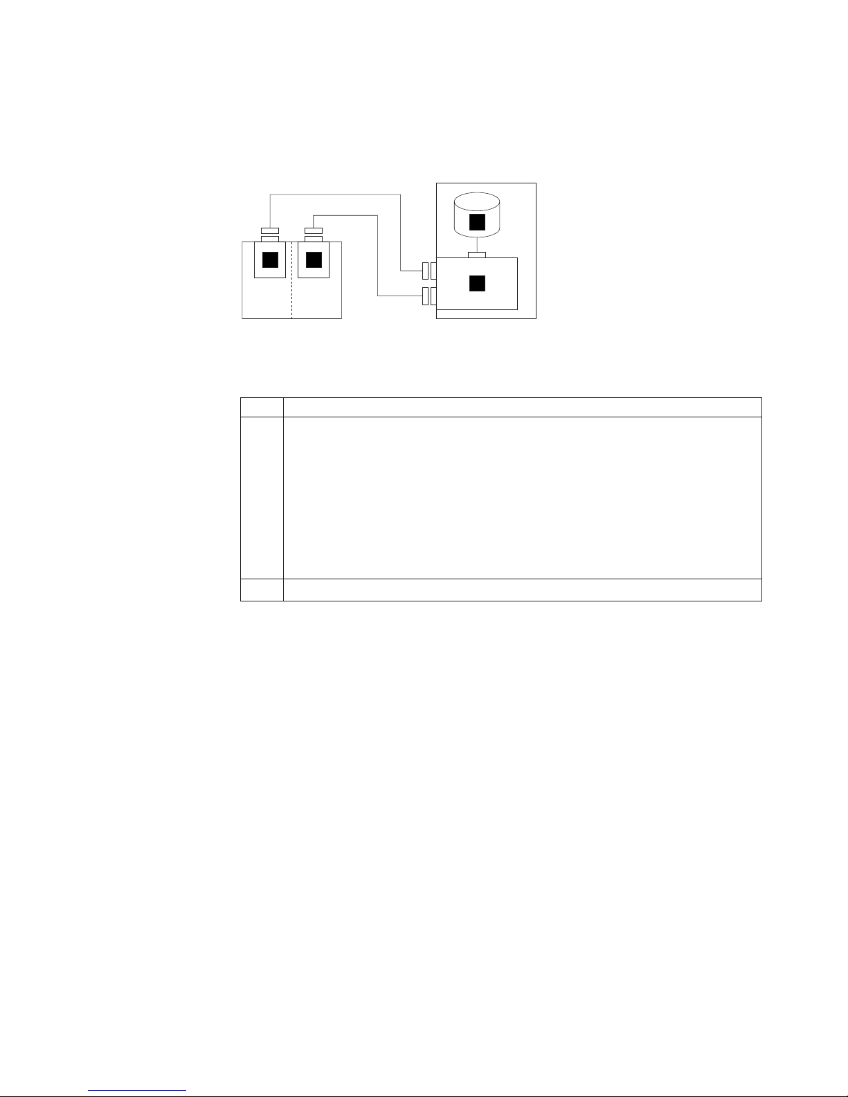
One adapter in one non-HACMP host system connected to one
2104 Model DS4 and an internal RAID array
Figure 54 shows one adapter in one non-HACMP host system connected to one
2104 Model DS4 and an internal RAID array (dual-bus mode).
3
11
2
2104 Subsystem
Host System
Figure 54. One adapter in one non-HACMP host system connected to one 2104 Model DS4
and an internal RAID array (dual-bus mode)
1 SCSI interface card.
2 SCSI adapter:
v PCI-X Dual Channel Ultra320 SCSI RAID Adapter (type number 5703, feature
code 5703)
v PCI 4-Channel Ultra3 SCSI RAID Adapter (type number 4-X, feature code 2498)
Important:
An RS/6000 or IBM Eserver pSeries computer running Linux for
pSeries uses the following to connect to the 2104 Model DS4:
PCI-X Dual Channel Ultra320 SCSI RAID Adapter (type number 5703, feature code
5703)
3 Internal RAID array.
Note: The SCSI address of the adapter that is connected to the 2104 Model DS4
must be different from the addresses of the installed disk drive modules.
Appendix B. Cable configurations 49
Page 82

One adapter in each of two non-HACMP host systems connected
to one 2104 Model DS4
Figure 55 shows one adapter in each of two non-HACMP host systems connected
to one 2104 Model DS4 (dual-bus mode).
11
2104 Subsystem
2
Host System
2
Host System
Figure 55. One adapter in each of two non-HACMP host systems connected to one 2104
Model DS4 (dual-bus mode)
1 SCSI interface card.
2 SCSI or SCSI RAID adapter of one of these types:
v PCI Dual-Channel Ultra3 SCSI Adapter (type number 4-Y, feature code 6203)
v PCI 4-Channel Ultra3 SCSI RAID Adapter (type number 4-X, feature code 2498)
v PCI-X Dual Channel Ultra320 SCSI adapter (type number 5702, feature code
5712)
v PCI-X Dual Channel Ultra320 SCSI RAID Adapter (type number 5703, feature
code 5703)
Connection can be to an integrated SCSI port instead of to a SCSI connector
Note:
on one of the listed SCSI adapters.
Important: An RS/6000 or IBM Eserver pSeries computer running Linux for
pSeries uses the following to connect to the 2104 Model DS4:
v PCI 4-Channel Ultra3 SCSI Adapter (type number 4-Y, feature code 6203)
v PCI-X Dual Channel Ultra320 SCSI Adapter (type number 5702, feature code
5712)
v PCI-X Dual Channel Ultra320 SCSI RAID Adapter (type number 5703, feature
code 5703)
Note: The SCSI address of the adapter that is connected to the 2104 Model DS4
must be different from the addresses of the installed disk drive modules. The
SCSI address of a second adapter, which is connected to a 2104 Model
DS4, can be the same address of the first adapter but must be different from
the addresses of the installed disk drive modules on the same SCSI bus.
50 Expandable Storage Plus 2104 Model DS4 Installation Guide
Page 83

One RAID adapter in each of two non-HACMP host systems
connected to two 2104 Model DS4s
Figure 56 shows one RAID adapter in each of two non-HACMP host systems
connected to two 2104 Model DS4s (dual-bus mode).
3
11
2
2104 Subsystem
Host System
3
11
2
2104 Subsystem
Figure 56. One RAID adapter in each of two non-HACMP host systems connected to two
2104 Model DS4s (dual-bus mode)
1 SCSI interface card.
2 SCSI RAID adapter:
v PCI-X Dual Channel Ultra320 SCSI RAID Adapter (type number 5703, feature
code 5703)
v PCI 4-Channel Ultra3 SCSI RAID Adapter (type number 4-X, feature code 2498)
Important:
An RS/6000 or IBM Eserver pSeries computer running Linux for
pSeries uses the following to connect to the 2104 Model DS4:
Host System
Notes:
1. The SCSI address of the adapter that is connected to the 2104 Model DS4
must be different from the addresses of the installed disk drive modules.
2. The external connectors on the SCSI RAID adapter cards and the internal RAID
connector must not share a SCSI bus.
PCI-X Dual Channel Ultra320 SCSI RAID Adapter (type number 5703, feature code
5703)
Appendix B. Cable configurations 51
Page 84

Invalid configurations
This section gives examples of configurations that are invalid.
Two adapters in one host system connected to one 2104 Model DS4
Figure 57 shows two adapters in one host system connected to one 2104 Model
DS4 (single-bus mode) .
2
11
2
2104 Subsystem
Host System
X
Figure 57. Two adapters in one host system connected to one 2104 Model DS4 (single-bus
mode). This configuration is invalid.
1 SCSI interface card.
2 SCSI adapter. This configuration is invalid for any type of adapter.
Note: This configuration is invalid when the 2104 Model DS4 is configured in
single-bus mode, but is valid when the 2104 Model DS4 is configured in
dual-bus mode. See page 46.
52 Expandable Storage Plus 2104 Model DS4 Installation Guide
Page 85

One adapter in one host system connected to two 2104 Model DS4s
through the SCSI interface cards
Figure 58 shows one adapter in one host system connected to two 2104 Model
DS4s through the SCSI Interface cards.
11
2104 Subsystem
11
2
Host System
X
2104 Subsystem
Figure 58. One adapter in one host system connected to two 2104 Model DS4s through the
SCSI Interface cards. This configuration is invalid.
1 SCSI interface card.
2 SCSI adapter. This configuration is invalid for any type of adapter.
Appendix B. Cable configurations 53
Page 86

One adapter in one host system connected to two 2104 Model DS4s
through a Y-cable (1)
Figure 59 shows one adapter in one host system connected to two 2104 Model
DS4s through a Y-cable (1).
3
11
2104 Subsystem
11
2
Host System
X
2104 Subsystem
Figure 59. One adapter in one host system connected to two 2104 Model DS4s through a
Y-cable (1). This configuration is invalid.
1 SCSI interface card.
2 SCSI adapter. This configuration is invalid for any type of adapter.
3 Y-cable. Not supported for any type of adapter that is used with the 2104 Model
DS4.
54 Expandable Storage Plus 2104 Model DS4 Installation Guide
Page 87

One adapter in one host system connected to two 2104 Model DS4s
through a Y-cable (2)
Figure 60 shows one adapter in one host system connected to two 2104 Model
DS4s through a Y-cable (2).
11
2104 Subsystem
11
3
2
Host System
X
2104 Subsystem
Figure 60. One adapter in one host system connected to two 2104 Model DS4s through a
Y-cable (2). This configuration is invalid.
1 SCSI interface card.
2 SCSI adapter. This configuration is invalid for any type of adapter.
3 Y-cable. Not supported for any type of adapter that is used with the 2104 Model
DS4.
Appendix B. Cable configurations 55
Page 88

One dual-channel non-RAID adapter in one host system connected to
two 2104 Model DS4s and internal disk drives
Figure 61 shows one dual-channel non-RAID adapter in one host system connected
to two 2104 Model DS4s and internal disk drives.
11
3 3
2104 Subsystem
2
11
Host System
X
2104 Subsystem
Figure 61. One dual-channel non-RAID adapter in one host system connected to two 2104
Model DS4s and internal disk drives. This configuration is invalid.
1 SCSI interface card.
2 PCI Dual-Channel Ultra3 SCSI Adapter (type number 4-Y, feature code 6203) and
PCI-X Dual Channel Ultra320 SCSI adapter (type number 5702, feature code 5712).
This configuration is invalid on this adapter because two internal and two external
attachments that are on the same SCSI bus exceed the capacity of the adapter.
3 Internal disk drives.
56 Expandable Storage Plus 2104 Model DS4 Installation Guide
Page 89

One RAID adapter in each of two host systems connected to two 2104
Model DS4s
Figure 62 shows one RAID adapter in each of two host systems connected to two
2104 Model DS4s. This configuration is invalid.
11
2104 Subsystem
11
3
2
Host System
3
X
2104 Subsystem
Figure 62. One RAID adapter in each of two host systems connected to two 2104 Model
DS4s. This configuration is invalid.
1 SCSI Interface card.
2 This configuration is invalid for RAID adapters because it cannot use HACMP.
3 Internal RAID disk drive array.
2
Host System
Appendix B. Cable configurations 57
Page 90

58 Expandable Storage Plus 2104 Model DS4 Installation Guide
Page 91

Notices
This information was developed for products and services offered in the U. S. A.
IBM may not offer the products, services, or features discussed in this document in
other countries. Consult your local IBM representative for information on the
products and services currently available in your area. Any reference to an IBM
product, program, or service is not intended to state or imply that only that IBM
product, program, or service may be used. Any functionally equivalent product,
program, or service that does not infringe on any IBM intellectual property right may
be used instead. However, it is the user’s responsibility to evaluate and verify the
operation of any non-IBM product, program, or service.
IBM may have patents or pending patent applications covering subject matter
described in this document. The furnishing of this document does not give you any
license to these patents. Yo u can send license inquiries, in writing to:
IBM Director of Licensing
IBM Corporation
North Castle Drive
Armonk, N.Y. 10504–1785
U.S.A.
The following paragraph does not apply to the United Kingdom or any other
country where such provisions are inconsistent with local law:
INTERNATIONAL BUSINESS MACHINES CORPORATION PROVIDES THIS
PUBLICATION “AS IS” WITHOUT WARRANTY OF ANY KIND, EITHER EXPRESS
OR IMPLIED, INCLUDING, BUT NOT LIMITED TO, THE IMPLIED WARRANTIES
OF NON-INFRINGEMENT, MERCHANTABILITY OR FITNESS FOR A
PARTICULAR PURPOSE. Some states do not allow disclaimer of express or
implied warranties in certain transactions, therefore, this statement may not apply to
you.
This information could include technical inaccuracies or typographical errors.
Changes are periodically made to the information herein; these changes will be
incorporated in new editions of the publication. IBM may make improvements and/or
changes in the product(s) and/or the program(s) described in this publication at any
time without notice.
Any references in this information to non-IBM Web sites are provided for
convenience only and do not in any manner serve as an endorsement of those
Web sites. The materials at those Web sites are not part of the materials for this
IBM product and use of those Web sites is at your own risk.
IBM may use or distribute any of the information you supply in any way it believes
appropriate without incurring any obligation to you.
© Copyright IBM Corp. 2003 59
Page 92

Trademarks
The following terms are trademarks of the International Business Machines
Corporation in the United States, other countries, or both:
AIX
IBM
RS/6000
Eserver
Intel is a registered trademark of Intel Corporation in the United States, other
countries, or both.
Other company, product, or service names may be trademarks or service marks of
others.
Electronic emission statements
This section gives the electronic emission notices or statements for the United
States and other countries.
Federal Communications Commission (FCC) statement
This equipment has been tested and found to comply with the limits for a class A
digital device, pursuant to Part 15 of the FCC Rules. These limits are designed to
provide reasonable protection against harmful interference when the equipment is
operated in a commercial environment. This equipment generates, uses, and can
radiate radio frequency energy and, if not installed and used in accordance with the
instruction manual, may cause harmful interference to radio communications.
Operation of this equipment in a residential area is likely to cause harmful
interference, in which case the user will be required to correct the interference at
his own expense.
Properly shielded and grounded cables and connectors must be used in order to
meet FCC emission limits. IBM is not responsible for any radio or television
interference caused by using other than recommended cables and connectors or by
unauthorized changes or modifications to this equipment. Unauthorized changes or
modifications could void the user’s authority to operate the equipment.
This device complies with Part 15 of the FCC Rules. Operation is subject to the
following two conditions: (1) this device may not cause harmful interference, and (2)
this device must accept any interference received, including interference that may
cause undesired operation.
Industry Canada compliance statement
Avis de conformite a la reglementation d’Industrie Canada: Cet appareil
numerique de la classe A est conform a la norme NMB-003 du Canada.
Chinese Class A warning statement
Attention: This is a Class A product. In a domestic environment, this product may
cause radio interference in which case the user may be required to take adequate
measures.
60 Expandable Storage Plus 2104 Model DS4 Installation Guide
Page 93

European Community compliance statement
This product is in conformity with the protection requirements of EC Council
Directive 89/336/EEC on the approximation of the laws of the Member States
relating to electromagnetic compatibility. IBM cannot accept responsibility for any
failure to satisfy the protection requirements resulting from a non-recommended
modification of the product, including the fitting of non-IBM option cards.
This product is in conformity with the EU council directive 73/23/EEC on the
approximation of the laws of the Member States relating to electrical equipment
designed for use within certain voltage limits. This conformity is based on
compliance with the following harmonized standard: EN60950.
This product has been tested and found to comply with the limits for class A
Information Technology Equipment according to European Standard EN 55022. The
limits for class A equipment were derived for commercial and industrial
environments to provide reasonable protection against interference with licensed
communication equipment.
Attention: This is a class A product. In a domestic environment, this product may
cause radio interference in which case the user may be required to take adequate
measures.
Where shielded or special cables (for example, cables fitted with ferrites) are used
in the test to make the product comply with the limits:
Properly shielded and grounded cables and connectors must be used in order to
reduce the potential for causing interference to radio and TV communications and
to other electrical or electronic equipment. Such cables and connectors are
available from IBM authorized dealers. IBM cannot accept responsibility for any
interference caused by using other than recommended cables and connectors.
Germany compliance statement
Zulassungsbescheinigung laut Gesetz ueber die elektromagnetische
Vertraeglichkeit von Geraeten (EMVG) vom 30. August 1995.
Dieses Geraet ist berechtigt, in Uebereinstimmung mit dem deutschen EMVG das
EG-Konformitaetszeichen - CE - zu fuehren.
Der Aussteller der Konformitaetserklaeung ist die IBM Deutschland.
Informationen in Hinsicht EMVG Paragraph 3 Abs. (2) 2:
Das Geraet erfuellt die Schutzanforderungen nach EN 50082-1 und EN 55022
Klasse A.
Notices 61
Page 94

EN 55022 Klasse A Geraete beduerfen folgender Hinweise:
Nach dem EMVG:_|t¹|
“Geraete duerfen an Orten, fuer die sie nicht ausreichend entstoert sind, nur mit
besonderer Genehmigung des Bundesministeriums fuer Post und
Telekommunikation oder des Bundesamtes fuer Post und Telekommunikation
betrieben werden. Die Genehmigung wird erteilt, wenn keine elektromagnetischen
Stoerungen zu erwarten sind.” (Auszug aus dem EMVG, Paragraph 3, Abs.4)
Dieses Genehmigungsverfahren ist nach Paragraph 9 EMVG in Verbindung mit der
entsprechenden
Kostenverordnung (Amtsblatt 14/93) kostenpflichtig.
Nach der EN 55022:
“Dies ist eine Einrichtung der Klasse A. Diese Einrichtung kann im Wohnbereich
Funkstoerungen verursachen. in diesem Fall kann vom Betreiber verlangt werden,
angemessene Massnahmen durchzufuehren und dafuer aufzukommen.”
Anmerkung:
Um die Einhaltung des EMVG sicherzustellen, sind die Geraete wie in den
Handbuechern angegeben zu installieren und zu betreiben.
Japanese Voluntary Control Council for Interference (VCCI) class 1
statement
Korean Government Ministry of Communication (MOC) statement
Please note that this device has been approved for business purposes with regard
to electromagnetic interference. If you find that this is not suitable for your use, you
may exchange it for one with a non-business use.
Taiwan class A compliance statement
62 Expandable Storage Plus 2104 Model DS4 Installation Guide
VS07171L
Page 95

Index
Numerics
2104 Model DS4
connecting
to the host system 29
connecting to the power source 27
installing 1
installing into a rack 2
installing into a RS/6000 2
installing into an IBM Eserver pSeries rack 2
installing into the rack 11
library xxix
parts list 2
switching on 31
testing 31
2104 Model TS4
library
xxix
A
about this document
related
publications xxix
who should read this document xxix
address
IBM
xxx
attention notices
description
ix
grounding of the 2104 Model DS4 xv
C
cable configurations, valid 35
caution notices, definition ix
check
machine,
machine, internal xi
safety label xii
checking
parts
rack items 2
checking the grounding
2104
Chinese class A compliance statement 60
comments, how to send xxx
conducting
external
internal machine checks xi
safety inspections x
configurations
invalid
valid 35
configuring to host system 33
connecting
2104
2104 Model DS4 to the power source 27
external xi
list 2
Model DS4 xv
machine checks xi
52
Model DS4 to the host system 29
D
danger notices, definition ix
director of licensing, address 59
disk drive module
reinstalling
14
removing 5
dual-bus mode configurations 45
dummy disk drive module
reinstalling
14
removing 5
E
electronic emission statements 60
electrostatic discharge x
environmental
notices
and statements xxvii
errors, collecting 34
European Community compliance statement 61
external machine checks xi
F
FCC
emission
limits 60
rules 60
statement 60
Federal Communications Commission (FCC)
statement 60
fire suppression systems xxvii
form
non-IBM
alteration attachment survey xi
reader comment, how to send xxx
fusing caution label xiii
G
Germany compliance statement 61
grounding check
2104
Model DS4 xv
H
heavy load label xiv
host system, connecting the 2104 Model DS4 29
how to send your comments xxx
I
IBM
address
trademarks 60
identifying
2104
disk drive modules 33
Industry Canada compliance statement 60
xxx
Model DS4 33
© Copyright IBM Corp. 2003 63
Page 96

inspection
2104
Model DS4 xi
safety, conducting x
safety, rack x
installation
2104
Model DS4 1
2104 Model DS4 into a rack 2
2104 Model DS4 into an empty rack 3
2104 Model DS4 into the rack 11
more than one 2104 Model DS4 into the rack 3
setting options 19
support rails 3
intellectual property 59
interference, radios and televisions 60
internal machine checks xi
invalid configurations 52
item check 2
J
Japanese Voluntary Control Council for Interference
(VCCI) class 1 statement 62
K
Korean Government Ministry of Communication (MOC)
statement 62
one (continued)
adapter
in each of two host systems connected to
two 2104 Model DS4 41
adapter in each of two non-HACMP host systems
connected to one 2104 Model DS4 50
adapter in one host system connected to one 2104
Model DS4 39
adapter in one host system connected to two 2104
Model DS4s 42
adapter in one host system connected to two 2104
Model DS4s and an internal RAID array 43
adapter in one host system connected to two 2104
Model DS4s through a Y-cable (1) 54
adapter in one host system connected to two 2104
Model DS4s through a Y-cable (2) 55
adapter in one host system connected to two 2104
Model DS4s through the SCSI interface cards 53
adapter in one non-HACMP host system connected
to one2104 Model DS4 and an internal RAID
array 49
dual-channel non-RAID adapter in one host system
connected to two 2104 Model DS4s and internal
disk drives 56
RAID adapter in each of two host systems connected
to two 2104 Model DS4s 57
RAID adapter in each of two non-HACMP host
systems connected to two 2104 Model DS4s 51
options, setting 19
L
label
2104
Model DS4 xii
check, safety xii
fusing caution xiii
heavy load xiv
linecord caution xii
power supply cover caution xiii
license, for patents 59
linecord caution label xii
M
machine checks
external
xi
internal xi
materials, recyclable xxvii
N
non-IBM alteration attachment survey form xi
notices
description
of 59
environmental xxvii
safety ix
O
one
adapter
in each of two host systems connected to
one 2104 Model DS4 44
P
patents 59
power
removing
from a 2104 Model DS4 xviii
source, connecting the 2104 Model DS4 27
supply, cover caution label xiii
preparing the rack 3
product
recycling
xxvii
publications
2104
Model DS4 and Model TS4 library xxix
Web sites xxx
R
rack
inspection
preparing (system or expansion) 3
radio interference 60
reader comment form processing xxx
recycling products xxvii
reinstalling
disk
dummy disk drive modules 14
related documents xxix
removing
disk
dummy disk drive modules 5
removing power
2104
RISC systems, operating with 33
x
drive modules 14
drive module 5
Model DS4 xviii
64 Expandable Storage Plus 2104 Model DS4 Installation Guide
Page 97

S
safety
electrostatic
external machine checks xi
inspection, how to conduct x
internal machine checks xi
label check xii
notices ix
removing power from a 2104 Model DS4 xviii
SCSI ID assignments 37
sending your comments xxx
single-bus mode configurations, valid 38
statements
Chinese
electronic emission 60
European Community compliance 61
Federal Communications Commission 60
Germany compliance 61
Industry Canada compliance 60
Japanese Voluntary Control Council for Interference
(VCCI) class 1 62
Korean Government Ministry of Communication
(MOC) 62
Taiwan class A compliance 62
switching on 2104 Model DS4 31
system service aids 33
systems, fire suppression xxvii
discharge x
class A compliance 60
T
Taiwan class A compliance statement 62
take-back program, product xxvii
testing the 2104 Model DS4 31
three adapters in two non-HACMP host systems
connected to two 2104 Model DS4s 47
trademarks 60
two
adapters
in one host system connected to one 2104
Model DS4 52
adapters in one host system connected to two 2104
Model DS4s 40
adapters in one non-HACMP host system connected
to one 2104 Model DS4 46
U
unauthorized changes or modifications 60
unconfiguring from host system 33
V
valid configurations 35
dual-bus mode 45
single-bus mode 38
table 37
W
Web sites xxx
who should read this document xxix
Index 65
Page 98

66 Expandable Storage Plus 2104 Model DS4 Installation Guide
Page 99

Readers’ comments — we would like to hear from you.
Expandable Storage Plus
2104 Model DS4 Installation Guide
Publication No. GA22-1053-00
Overall, how satisfied are you with the information in this book?
Overall satisfaction hhhhh
How satisfied are you that the information in this book is:
Accurate hhhhh
Complete hhhhh
Easy to find hhhhh
Easy to understand hhhhh
Well organized hhhhh
Applicable to your tasks hhhhh
Please tell us how we can improve this book:
Very Satisfied Satisfied Neutral Dissatisfied Very Dissatisfied
Very Satisfied Satisfied Neutral Dissatisfied Very Dissatisfied
Thank you for your responses. May we contact you? h Yes h No
When you send comments to IBM, you grant IBM a nonexclusive right to use or distribute your comments in any
way it believes appropriate without incurring any obligation to you.
Name
Company or Organization
Phone No.
Address
Page 100

___________________________________________________________________________________________________
Readers’ Comments — We’d Like to Hear from You
GA22-1053-00
Fold
_________________________________________________________________________________________
and Tape Please do not staple Fold and Tape
NO
POSTAGE
NECESSARY
MAILED IN THE
IF
STATES
UNITED
Cut or Fold
Line
Along
BUSINESS REPLY MAIL
FIRST-CLASS MAIL PERMIT NO. 40 ARMONK, NEW YORK
POSTAGE WILL BE PAID BY ADDRESSEE
International Business Machines Corporation
RCF Processing Department
Dept. M86/Bldg.050-3
5600 Cottle Road
San Jose, CA
U.S.A. 95193-0001
_________________________________________________________________________________________
and Tape Please do not staple Fold and Tape
Fold
GA22-1053-00
Cut
Along
or Fold
Line
 Loading...