

Page 1

IBM TotalStorage SAN16M-R SAN Router
Installation an d Service Manual
Service information: 2027 / R16
Read Before Using
This product contains software that is licensed under written license agreements. Your use of such software is subject to
the license agreements under which they are provided.
GC26-7744-02
Page 2

Page 3

IBM TotalStorage SAN16M-R SAN Ro uter
Installation an d Service Manual
Service information: 2027 / R16
GC26-7744-02
Page 4

Third Edition (February 2007)
© Copyright International Business Machines Corporation 2005, 2007. All rights reserved.
US Government Users Restricted Rights – Use, duplication or disclosure restricted by GSA ADP Schedule Contract
with IBM Corp.
Page 5

© Copyright IBM Corp. 2007
iii
Contents
Chapter 1 Overview
Introduction..........................................................................................1
SAN Router...........................................................................................2
SAN Router physical description...............................................4
Operational features.....................................................................5
Element Manager overview ...............................................................7
Software requirements........................................................................8
Before installing the SAN Router ......................................................9
Required tools and materials ......................................................9
Package contents.........................................................................10
Safety precautions.......................................................................10
Chapter 2 Installing and connecting the SAN Router
Installing the SAN Router ................................................................13
Task 1: Verifying installation requirements...................................14
Gathering preliminary site information..................................14
Task 2: Mounting the SAN Router..................................................16
Surface mounting the SAN Router ..........................................16
Mounting the SAN Router in an equipment rack..................16
Task 3: Powering up the SAN Router.............................................17
Task 4: Preparing to configure the SAN Router............................19
Task 5: Connecting the VT100 or emulation terminal to the
RS-232 management port..................................................................20
Task 6: Preparing the SAN Router for Element Manager access 21
Set the IP address for the network management port using
CLI.................................................................................................21
Task 7: Initiating the Element Manager..........................................23
Before you connect the SAN Router to the network .............23
Task 8: Connecting Intelligent/TCP ports .....................................24
Task 9: Connecting fibre channel ports ..........................................24
Fibre Channel port connections................................................24
Task 10: Configure and enable call home notification .................25
IP address management....................................................................26
SFP connectors and cables................................................................26
SFP cable requirements..............................................................27
Cable specifications ...........................................................................27
Cable guidelines.................................................................................28
Management port pinouts................................................................29
Page 6

SAN16M-R SAN Router Installation And Service Manual
iv
Serial port pinout........................................................................29
RJ45 port pinout..........................................................................30
Installing an SFP device....................................................................31
SAN Router firmware default values.............................................32
Chapter 3 Maintenance and troubleshooting
Upgrading firmware (E/OSi) ..........................................................41
Requirements for upgrading firmware (4.6/4.7 to 5.0) ........42
Checklist for migrating to 5.0 version .....................................42
Downloading firmware .............................................................43
Upgrading bootrom (E/OSi)............................................................46
Resetting the system..........................................................................47
Troubleshooting overview ...............................................................48
SAN Router physical connections............................................50
SAN Router LEDs..............................................................................52
SAN Router troubleshooting ...........................................................53
GE port troubleshooting...................................................................56
Serial Management Console troubleshooting ...............................57
Retrieving the system log.................................................................57
Accessing SNMP alerts or alarms ...................................................58
Performing a loopback test............................................................... 60
Other resources for troubleshooting...............................................60
SANvergence Manager..............................................................61
E/OSi CLI.................................................................................... 61
Element Manager........................................................................61
Cleaning fiber-optic components ....................................................61
Chapter 4 Parts catalog
Parts catalog........................................................................................ 63
RoHS information.......................................................................63
Front-accessible FRUs .......................................................................64
Rear-accessible FRUs.........................................................................64
Miscellaneous parts...........................................................................65
Power cords and receptacles............................................................66
Chapter 5 Removal and replacement procedures
Procedural notes ................................................................................69
RRP 1: SFP optical transceiver......................................................... 69
RRP 2: Redundant power supply....................................................72
Page 7

v
Contents
Appendix A Specifications
Port characteristics ............................................................................75
Size and weight .................................................................................75
Power requirements ..........................................................................75
Power consumption ..........................................................................76
Environmental requirements ...........................................................76
Compatible transceivers ...................................................................76
1G FC multi-mode, LC connectors...........................................76
1000Base-SX (GE) multi-mode, LC connectors.......................77
1G FC single-mode, LC connectors..........................................77
1000Base-LX (GE) single-mode, LC connectors......................77
1G FC copper HSSDC2 transceiver..........................................77
SFP cable requirements..............................................................78
Notices ............................................................................................................................79
Trademarks .........................................................................................80
Electronic emission notices, certifications, other notices..............81
Laser Compliance Statement.....................................................81
Federal Communications Commission (FCC) Statement .....81
Canadian EMC Statements........................................................81
United States and Canada UL Certification............................82
International Safety Conformity Declaration (CB Scheme)..82
European Union Conformity Declarations and Directives (CE
Mark).............................................................................................82
European Union EMC and Safety Declaration (N-Mark).....83
Argentina IRAM Certification...................................................83
Australia and New Zealand C-Tick Mark...............................84
People’s Republic of China CCC Mark....................................84
Chinese National Standards Statement ...................................84
German TÜV GS Mark...............................................................85
Japanese VCCI Statement ..........................................................85
Korean MIC Mark.......................................................................85
Mexican NOM Mark...................................................................85
Russian GOST Certification.......................................................86
South African SABS Certification.............................................86
Page 8

SAN16M-R SAN Router Installation And Service Manual
vi
Page 9

© Copyright IBM Corp. 2007
vii
Tables
1 IBM products and SAN management documentation—E/OSi .............. xii
2 SAN Router front view keys ........................................................................... 3
3 SAN Router features ........................................................................................ 5
4 Element Manager software functions ........................................................... 7
5 SANvergence Manager and Element Manager platform requirement .... 9
6 Installation task summary ............................................................................. 13
7 SAN Router front panel locations ................................................................ 18
8 Default management and SAN Router addresses ..................................... 19
9 Other defaults ................................................................................................. 19
10 Terminal emulator settings ........................................................................... 21
11 Fibre Channel cables ...................................................................................... 27
12 Compatible cable types ................................................................................. 28
13 Serial port pinout description ....................................................................... 29
14 RJ45 pinout description ................................................................................. 30
15 SAN Router firmware default values via Element Manager ................... 32
16 SAN Router firmware default values via SANvergence .......................... 38
17 SAN Router E/OSi and bootrom versions ................................................ 46
18 Resetting the system ...................................................................................... 47
19 Physical connections and port locations ..................................................... 49
20 LEDs on the SAN Router .............................................................................. 52
21 SAN Router troubleshooting summary ...................................................... 53
22 GE port problems and solutions .................................................................. 56
23 Serial Management Console troubleshooting ............................................ 57
24 SNMP alerts or alarm definitions ................................................................ 59
25 FRU List-front accessible ............................................................................... 64
26 FRU List-rear accessible ................................................................................ 64
27 Miscellaneous Parts List ................................................................................ 65
28 Power cord part number list ......................................................................... 67
29 Small form factor pluggable (SFP) cables ................................................... 78
Page 10

SAN16M-R SAN Router Installation And Service Manual
viii
Page 11

© Copyright IBM Corp. 2007
ix
Figures
1 The SAN Router, front view ........................................................................... 3
2 The SAN Router, rear view ............................................................................. 4
3 SAN Router ports and LEDs ......................................................................... 18
4 Management port to management terminal connection .......................... 21
5 Intelligent ports .............................................................................................. 24
6 Fibre channel ports (two of twelve) ............................................................. 25
7 IP addresses associated with SAN Router .................................................. 26
8 Serial port pinout ............................................................................................ 29
9 RJ45 Pinout ...................................................................................................... 30
10 Firmware Upgrade dialog box ..................................................................... 44
11 Activate Boot Location dialog box ............................................................... 45
12 Reset Options dialog box .............................................................................. 48
13 Physical connections and ports .................................................................... 49
14 Power supply FRUs ....................................................................................... 50
15 Retrieve the system log dialog box .............................................................. 58
16 Power supply alert shown in trap viewer .................................................. 60
17 Clean fiber-optic components ....................................................................... 62
18 Miscellaneous parts ........................................................................................ 65
19 Power cords ..................................................................................................... 66
20 Power supply removal .................................................................................. 73
Page 12

SAN16M-R SAN Router Installation And Service Manual
x
Page 13

© Copyright IBM Corp. 2007
xi
Preface
This manual provides the information required to install and prepare
the SAN Router for configuration to operate with E/OSi version 4.6
in an Ethernet/IP or Fibre Channel (FC) data network.
Who should use this manual
This publication is intended for trained service representatives
experienced with storage area network (SAN) and Fibre Channel
technology, and for IT professionals including experienced Data
Networking Administrators and System Architects.
Related publications
Other publications that provide additional information about the
switch include:
• IBM TotalStorage Products in a SAN Environment Planning Manual,
GC26-7675.
• McDATA Eclipse 2640 SAN Router Administration and Configuration
Manual, 620-000203.
• McDATA SANvergence Manager User Manual, 620-000189.
• McDATA E/OSi Command Line Interface User Manual, 620-000207.
• IBM TotalStorage SAN16M-R SAN Router Rack-Mount Installation
Instructions, 958-000432-000.
• IBM TotalStorage SANC40M Cabinet Installation and Service Manual,
GC26-7746.
• IBM eServer Safety Notices, G229-9054.
IBM and McDATA publications
Some of the documentation that is applicable to IBM TotalStorage
products is provided by McDATA Corporation. The documents often
are identified by a McDATA product name that corresponds to the
IBM product name. Table 1 lists the IBM product name, the
Page 14

SAN16M-R SAN Router Installation And Service Manual
xii
corresponding McDATA product name, the applicable software, and
the documentation that is relevant to the product.
Ordering manuals
To order a printed copy of this publication, contact your IBM Branch
office or you can locate (and purchase) books online at:
http://www.elink.ibmlink.ibm.com.
Where to get help
Contact IBM for technical support, which includes hardware support,
all product repairs, and ordering of spare parts, go to:
http://www.ibm.com/servers/storage/support/san/index.html.
You can also contact IBM within the United States at 1-800-IBMSERV
(1-800-426-7378). For support outside the United States, you can find
the service number at
http://www.ibm.com/planetwide/.
Table 1 IBM products and SAN management documentation—E/OSi
IBM TotalStorage
product name,
and machine type
and model
McDATA product
name
Related firmware
and SAN
management
product
Relevant documentation
SAN16M-R SAN
Router
• 2027-R16
Eclipse 2640 SAN
Router
•E/OSi
• SANvergence
• McDATA E/OSi Command Line Interface User Manual
(620-000207)
• McDATA E/OSi SNMP Support Manual (620-000228)
• McDATA SANvergence Manager User Manual (620-000189)
• McDATA Eclipse 2640 SAN Router Administration and
Configuration Manual (620-000203)
SAN04M-R SAN
Router
• 2027-R04
Eclipse 1620 SAN
Router
•E/OSi
• SANvergence
• McDATA E/OSi Command Line Interface User Manual
(620-000207)
• McDATA E/OSi SNMP Support Manual (620-000228)
• McDATA SANvergence Manager User Manual (620-000189)
• McDATA Eclipse 1620 SAN Router Administration and
Configuration Manual (620-000205)
Page 15

xiii
How to send your comments
Your feedback is important in helping us provide the most accurate
and high-quality information. If you have comments or suggestions
for improving this document, you can send us comments
electronically by using the following addresses:
• Internet: starpubs@us.ibm.com
• IBMLink™ from U.S.A.: STARPUBS at SJEVM5
• IBMLink from Canada: STARPUBS at TORIBM
• IBM Mail Exchange: USIB3VVD at IBMMAIL
You can also mail your comments by using the Reader Comment
Form in the back of this manual or direct your mail to:
International Business Machine Corporation
Information Development
Department GZW
9000 South Rita Road
Tucson, Arizona 85744-001 U.S.A
When you send information to IBM, you grant IBM a nonexclusive
right to use or distribute the information in any way it believes
appropriate without incurring any obligation to you.
Safety and environmental notices
ATTENTION ! The IBM Total Storage SAN16M-R is not designed to be
installed and serviced by customers. Installation and servicing of the
SAN16M-R should be performed by qualified service representatives only.
Safety notices and labels
When using this product, observe the danger, caution, and attention
notices contained in this guide. The notices are accompanied by
symbols that represent the severity of the safety condition. The
danger and caution notices are listed in numerical order based on
their IDs, which are displayed in parentheses, for example (D004), at
the end of each notice. Use this ID to locate the translations of these
Page 16
SAN16M-R SAN Router Installation And Service Manual
xiv
danger and caution notices in the IBM eServer Safety Notices
(G229-9054) publication, which is on the CD-ROM that accompanies
this product.
The following notices and statements are used in this document.
They are listed below in order of increasing severity of potential
hazards. Follow the links for more detailed descriptions and
examples of the danger, caution, and attention notices in the sections
that follow.
• Note: These notices provide important tips, guidance, or advice.
• Attention notices: These notices indicate potential damage to
programs, devices, or data.
• Caution notices: These statements indicate situations that can be
potentially hazardous to you.
• Danger notices: These statements indicate situations that can be
potentially lethal or extremely hazardous to you. Safety labels are
also attached directly to products to warn of these situations.
Danger notices A danger notice calls attention to a situation that is potentially lethal
or extremely hazardous to people. A lightning bolt symbol
accompanies a danger notice to represent a dangerous electrical
condition. Read and comply with the following danger notices before
installing or servicing this device.
DANGER
To prevent a possible shock from touching two surfaces with different
protective ground (earth), use one hand, when possible, to connect or
disconnect signal cables.
(D001)
DANGER
Overloading a branch circuit is potentially a fire hazard and a shock
hazard under certain conditions. To avoid these hazards, ensure that
your system electrical requirements do not exceed branch circuit
protection requirements. Refer to the information that is provided
Page 17
xv
with your device or the power rating label for electrical
specifications.
(D002)
DANGER
If the receptacle has a metal shell, do not touch the shell until you
have completed the voltage and grounding checks. Improper wiring
or grounding could place dangerous voltage on the metal shell. If any
of the conditions are not as described, STOP. Ensure the improper
voltage or impedance conditions are corrected before proceeding.
(D003)
DANGER
An electrical outlet that is not correctly wired could place hazardous
voltage on metal parts of the system or the devices that attach to the
system. It is the responsibility of the customer to ensure that the
outlet is correctly wired and grounded to prevent an electrical shock.
(D004)
A comprehensive danger notice provides instructions on how to
avoid shock hazards when servicing equipment. Unless instructed
otherwise, follow the procedures in the following danger notice.
DANGER
Electrical voltage and current from power, telephone, and
communication cables are hazardous. To avoid a shock hazard:
• Do not connect or disconnect any cables or perform installation,
maintenance, or reconfiguration of this product during an
electrical storm.
• Connect all power cords to a properly wired and grounded
electrical outlet. Ensure outlet supplies proper voltage and phase
rotation according to the system rating plate.
• Connect any equipment that will be attached to this product to
properly wired outlets.
• When possible, use one hand only to connect or disconnect signal
cables.
Page 18
SAN16M-R SAN Router Installation And Service Manual
xvi
• Never turn on any equipment when there is evidence of fire,
water, or structural damage.
• Disconnect the attached power cords, telecommunications
systems, networks, and modems before you open the device
covers, unless instructed otherwise in the installation and
configuration procedures.
• Connect and disconnect cables as described below when
installing, moving, or opening covers on this product or attached
devices.
To Disconnect:
1. Turn everything OFF (unless instructed otherwise).
2. Remove power cords from the outlet.
3. Remove signal cables from connectors.
4. Remove all cables from devices.
To Connect:
1. Turn everything OFF (unless instructed otherwise).
2. Attach all cables to devices.
3. Attach signal cables to connectors.
4. Attach power cords to outlet.
5. Turn device ON.
(D005)
Labels As an added precaution, safety labels are often installed directly on
products or product components to warn of potential hazards. These
can be either danger or caution notices, depending upon the level of
the hazard.
The actual product safety labels may differ from these sample safety
labels:
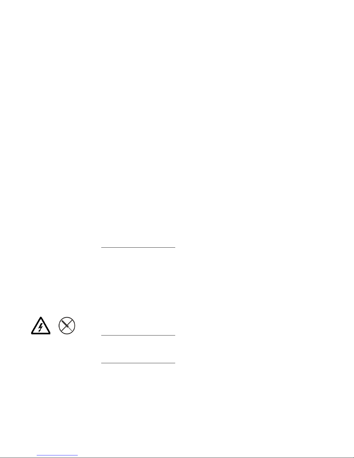
DANGER
Hazardous voltage, current, or energy levels are present inside any
component that has this label attached.
(L001)
Do not service, there are no serviceable parts.
Page 19
xvii
DANGER
Rack-mounted devices are not to be used as a shelf or work space.
(L002)
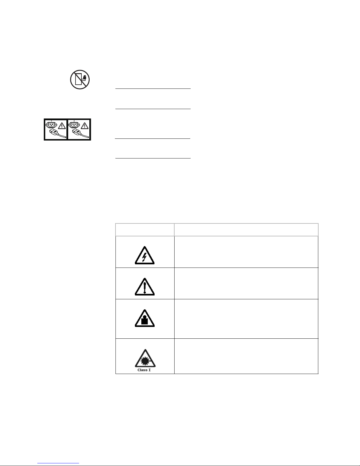
DANGER
Multiple power cords
(L003)
To remove all power to the device, disconnect all power cords.
Caution notices A caution notice calls attention to a situation that is potentially
hazardous to people because of some existing condition. A caution
notice can be accompanied by different symbols, as in the examples
below:
Read and comply with the following caution notices before installing
or servicing this device.
If the symbol is... It means....
A hazardous electrical condition with less severity than electrical
danger.
A generally hazardous condition not represented by other safety
symbols.
>18kg (39.7 lb)
A specification of product weight that requires safe lifting
practices. The weight range of the product is listed below the
graphic, and the wording of the caution varies, depending on the
weight of the device.
A hazardous condition due to the use of a laser in the product.
Laser symbols are always accompanied by the classification of
the laser as defined by the U. S. Department of Health and
Human Services (for example, Class I, Class II, and so forth).
Page 20
SAN16M-R SAN Router Installation And Service Manual
xviii
CAUTION
This part or unit is heavy, but has a weight smaller than 18 kg
(39.7 lb.). Use care when lifting, removing, or installing this part or
unit.
(C008)
CAUTION
The doors and covers to the product are to be closed at all times
except for service by trained service personnel. All covers must be
replaced and doors locked at the conclusion of the service
operation.
(C013)
CAUTION
The system contains circuit cards and/or assemblies that contain
lead solder. To avoid the release of lead (Pb) into the environment,
do not burn. Discard the circuit card as instructed by local
regulations.
(C014)
CAUTION
Ensure the building power circuit breakers are turned off BEFORE
you connect the power cord(s) to the building power.
(C023)
CAUTION
This assembly contains mechanical moving parts. Use care when
servicing this assembly.
(C025)
Page 21
xix
CAUTION
Servicing of this product or unit is to be performed by trained
service personnel only.
(C032)
Attention notices An attention notice indicates the possibility of damage to a program,
device, or system, or to data. An exclamation point symbol may
accompany an attention notice, but is not required. A sample
attention notice follows:
ATTENTION ! Do not bend a fibre cable to a radius less than 5 cm (2 in.); you
can damage the cable. Tie wraps are not recommended for optical cables
because they can be easily overtightened, causing damage to the cable.
Laser safety This equipment contains Class 1 laser products, and complies with
FDA radiation Performance Standards, 21 CFR Subchapter J and the
international laser safety standard IEC 60825.
CAUTION
This product may contain one or more of the following: CD-ROM,
DVD-ROM, DVD-RAM, or laser module, which are Class 1 laser
products. Please note the following:
• Do not remove the covers. Removing the covers of the laser
product could result in exposure to hazardous laser radiation.
There are no serviceable parts inside the device.
• Use of the controls or adjustments or performance of
procedures other than those specified herein might result in
hazardous radiation exposure.
(C026)
CAUTION
Data processing environments can contain equipment transmitting
on system links with laser modules that operate at greater than
Class 1 power levels. For this reason, never look into the end of an
optical fiber cable or open receptacle.
(C027)
Page 22

SAN16M-R SAN Router Installation And Service Manual
xx
Environmental notices
Use the environmental statements and warning in this section to
guide you when using this product and in properly disposing of the
product and its components.
Product recycling
and disposal
This unit must be recycled or discarded according to applicable local
and national regulations. IBM encourages owners of information
technology (IT) equipment to responsibly recycle their equipment
when it is no longer needed. IBM offers a variety of product return
programs and services in several countries to assist equipment
owners in recycling their IT products. Information on IBM product
recycling offerings can be found on IBM’s Internet site at
http://www.ibm.com/ibm/environment/products/prp.shtml
Note: This mark applies only to countries within the European Union
(EU) and Norway.
Appliances are labeled in accordance with European Directive
2002/96/EC concerning waste electrical and electronic equipment
(WEEE). The Directive determines the framework for the return and
recycling of used appliances as applicable throughout the European
Union. This label is applied to various products to indicate that the
product is not to be thrown away, but rather reclaimed upon end of
life per this Directive.
Page 23

xxi
In accordance with the European WEEE Directive, electrical and
electronic equipment (EEE) is to be collected separately and to be
reused, recycled, or recovered at end of life. Users of EEE with the
WEEE marking per Annex IV of the WEEE Directive, as shown
above, must not dispose of end of life EEE as unsorted municipal
waste, but use the collection framework available to customers for the
return, recycling and recovery of WEEE. Customer participation is
important to minimize any potential effects of EEE on the
environment and human health due to the potential presence of
hazardous substances in EEE. For proper collection and treatment,
contact your local IBM representative.
Battery return
program
This product may contain sealed lead acid, nickel cadmium, nickel
metal hydride, lithium, or lithium ion battery. Consult your user
manual or service manual for specific battery information. The
battery must be recycled or disposed of properly. Recycling facilities
may not be available in your area. For information on disposal of
batteries outside the United States, go to
http://www.ibm.com/ibm/environment/products/batteryrecycle.s
html or contact your local waste disposal facility.
In the United States, IBM has established a return process for reuse,
recycling, or proper disposal of used IBM sealed lead acid, nickel
cadmium, nickel metal hydride, and other battery packs from IBM
Equipment. For information on proper disposal of these batteries,
contact IBM at 1-800-426-4333. Please have the IBM part number
listed on the battery available prior to your call.
For Taiwan:
Page 24
SAN16M-R SAN Router Installation And Service Manual
xxii
Please recycle batteries.
Cable warning
WARNING
Handling the cord on this product or cords associated with
accessories sold with this product, will expose you to lead, a
chemical known to the State of California to cause cancer, and birth
defects or other reproductive harm. Wash hands after handling.
Page 25

© Copyright IBM Corp. 2007
1
Chapter 1: Overview
Use the links below to access the major topics in this chapter.
Introduction
IBM offers a family of Fibre Channel switching products that allow
implementation of a storage area network (SAN) topology in Fibre
Channel Protocol (FCP) or fibre connection (FICON) environments.
IBM offers several alternatives to build a robust and scalable SAN
infrastructure that meets the customer’s data center requirements.
This manual provides information and procedures for installing the
SAN Router, and for configuring and managing by the SAN Router
Element Manager and the Enterprise Fabric Connectivity Manager.
The SAN Router Element Manager is a Web-based Java applet which
is used to configure, monitor, and troubleshoot the router.
SANvergence Manager is a Java-based collection of software tools for
managing a multi-protocol storage fabric consisting of McDATA
switches and gateways.
Both applications can be used to configure and manage the SAN
Router. SAN Router Element Manager is used to configure an
individual SAN Router while SANvergence Manager is used to
configure and manage multiple SAN Routers in a SAN environment.
When used with SANvergence, SAN Router Element Manager can be
launched from SANvergence.
Section Page
Introduction 1
SAN Router 2
SAN Router physical description 4
Element Manager overview 7
Before installing the SAN Router 9
Safety precautions 10
Page 26

SAN16M-R SAN Router Installation And Service Manual
2
SAN Router
The SAN Router (also referred to as router in this manual) supports
iSCSI, iFCP, and R_Port for connecting to both IP backbones and
legacy Fibre Channel (FC) fabrics. The SAN Router connects to a
wide range of Fibre Channel and IP end systems. The SAN Router
supports TCP/IP routing over extended distances at wire speed.
The SAN Router can be deployed for multiple, concurrent
applications, including SAN routing in the data center (mSAN
routing), SAN routing over distance (iSAN routing) for disaster
recovery, and iSCSI access to Fibre Channel storage.
mSAN routing enables you to build very large, stable fabrics where
faults in one part of the network do not impact traffic in other parts.
For disaster recovery, the backup site can be quite distant, thanks to
Fast Write technology, which can sustain wire-speed throughput in
spite of high-link latency. The TCP ports on the SAN Router can
support iSCSI access to Fibre Channel storage.
The SAN Router offers:
• mSAN internetworking for scalable and fault-tolerant SANs.
• Compression for increased bandwidth.
• Support for full fabric and private and public loop FC devices.
• Fast Write™ technology for maximizing throughput across long
distances.
The SAN Router is shown in Figure 1, The SAN Router, front view, and
described in SAN Router physical description. A rear view with power
supply locations is shown in Figure 2, The SAN Router, rear view.
Page 27
3
Chapter 1: Overview
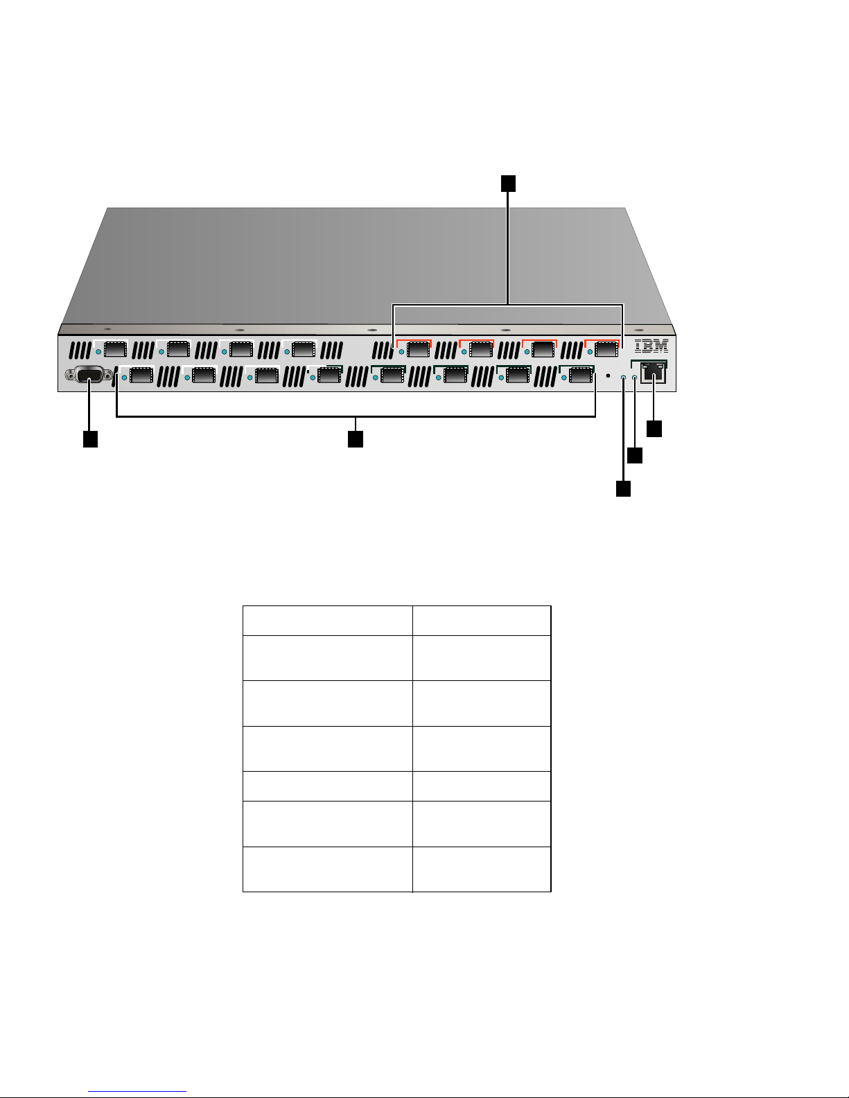
Figure 1 The SAN Router, front view
9 12
11
10
1
3
2
4
5
7
6 8
13
15
14 16
SYS
10/100
CONSOLE
i2640002
2
1
3
4
6
5
Tabl e 2 SAN Router front view keys
Key Definition
1 Management port (RS-232 Serial)
2 FC ports 1-12, FC 1 or 2 Gbps, GE 1
Gbps
3 Intelligent ports 13-16, iSCSI or iFCP
4 System status LED
5 Management port status LED
6 Manage port (RJ-45) 10/100
Page 28

SAN16M-R SAN Router Installation And Service Manual
4
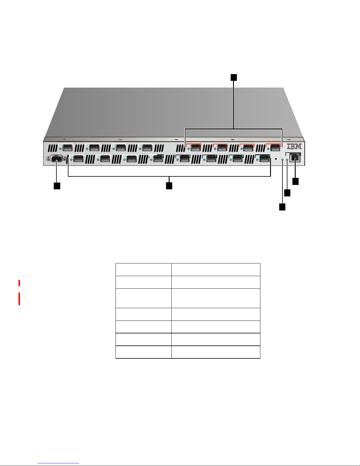
Figure 2 The SAN Router, rear view
SAN Router physical description
All ports and connectors are located on the front of the SAN Router,
except for the power connectors, as described in the following
paragraphs. The rear of the SAN Router contains only the power
connectors and cooling fans. The Field Replaceable Units (FRUs) are
the optical transceivers, power supplies (which include internal fans),
and base machine.
Power
connections
There are two standard power connections located on the rear of the
SAN Router. Each of these power connections supplies AC power to
a different power supply for power redundancy and backup. Either
power supply can support the SAN Router operation, but it is
recommended that both be connected, each to a different power
source.
NOTE: If one power supply fails, the SAN Router will continue to operate
but the failed power supply should be replaced as soon as possible to retain
redundancy.
Fibre channel
ports
There are twelve user-configurable fibre channel ports located on the
front of the SAN Router, labeled 1 through 12. These port connections
hold SFP transceivers that support FC connectivity at 1 or 2 Gbps or
GE connectivity at 1 Gbps. The ports can be configured as:
• FC_Auto (default)
•FL_Port
• F_Port
• L_Port
• R_Port
i2640003
Page 29

5
Chapter 1: Overview
To the left of each FC port is an LED that indicates the configuration
and status of the associated port. For more information about these
LEDs, see Table 20 on page 52.
Intelligent ports
for IP connection
The SAN Router provides four intelligent ports for Gig Ethernet (GE)
connectivity, labeled 13 through 16. Each intelligent port for IP
connectivity can be configured for either Internet Small Computer
Systems Interface (iSCSI) or Internet Fibre Channel Protocol (iFCP).
Management ports There are two management ports located on the front of the SAN
Router. An RS-232 serial port that can be connected to a VT100
terminal emulator for access to SAN Router console that supports the
Command Line Interface (CLI), and an RJ45 port that can be
connected to the LAN for out-of-band management using the SAN
Router Element Manager or the SANvergence Manager. The RJ45
management port can be accessed by any PC on the LAN with a web
browser or Telnet based CLI.
Operational features
The SAN Router features are described in Table 3, SAN Router
features. Some features are optional and may not be present in some
SAN Router software versions.
Tabl e 3 SAN Router features
Feature Description
Intelligent ports Four intelligent ports, which can be configured for
Internet Small Computer Systems Interface (iSCSI) or
Internet Fibre Channel Protocol (iFCP). An Intelligent
port is also referred as TCP port.
Internet Fibre Channel
Protocol (iFCP)
standards track
protocols
The SAN Router supports the IETF draft standard for
iFCP, which provides connectivity and networking for
existing Fibre Channel devices over a TCP/IP network.
iSCSI The SAN Router supports IETF standard based iSCSI
protocol.A TCP port can be configured for either iSCSI
or iFCP.
Page 30

SAN16M-R SAN Router Installation And Service Manual
6
R_Port Support for FC-SW2 standard E_Port as well as
Brocade interoperability mode allows you to fully
integrate the SAN Router into an existing Fibre Channel
SAN that includes one or more Fibre Channel switches.
Fast write The Fast Write software feature available on intelligent
ports improves the performance of write operations
between Fibre Channel initiators and targets in a Wide
Area Network (WAN). The improved speed depends on
the WAN Round Trip Time (RTT), available buffer space
on the target, number of concurrent I/Os supported by
the application and application I/O size.
Router Zoning Using SANvergence Manager, network management
software, or the command line interface (CLI), you can
create zones across networks.
You can use zone sets for periodic reallocation of
network resources. For example, you can have one set
of zones for daytime data transactions and another set of
zones for nighttime backups. You can create zones
across networks.
Real-time and historical
system logs
The Element Manager and LogViewer can be used to
look at current system log messages from the connected
SAN Router.
Compression Compression technology available on intelligent ports
identifies repetitive patterns in a data stream and
represents the same information in a more compact and
efficient manner. By compressing the data stream, more
data can be sent across the network even if slower link
speeds are used.
Jumbo Frames Since the maximum Fibre Channel payload size is 2112
bytes, two regular Ethernet frames are required. The
Jumbo Frame option extends the Ethernet payload to
2112 bytes. With the support of Jumbo Frames, a Fibre
Channel frame can be mapped to just one Ethernet
frame, providing more efficient transport. For iSCSI
traffic, up to 4K size frames are supported.
Table 3 SAN Router features
Feature Description
Page 31

7
Chapter 1: Overview
Element Manager overview
The SAN Router Element Manager, a Web-based Java applet, is used
to configure, monitor, and troubleshoot the router. The Element
Manager software configuration and monitoring functions are listed
in Table 4, Element Manager software functions. See the Administration
and Configuration Manual for specific configuration procedures using
the Element Manager.
Tabl e 4 Element Manager software functions
Feature Description
SAN Router
Configuration
SAN Router Inband IP Address
Date-Time
System Properties
Default Zoning Behavior
Password Management
SNMP Traps
Port Configuration Fibre Channel and TCP Ports (supporting iSCSI and
iFCP)
Management Port
Static Routing
iFCP Gateway
Configuration
iFCP Setup
Remote Connection Configuration
Port Redundancy Configuration
iSCSI Configuration Device Configuration
RADIUS Server Configuration
Page 32

SAN16M-R SAN Router Installation And Service Manual
8
To login to the SAN Router and launch Element Manager, you must
first install and prepare the SAN Router for out-of-band
management, as described in this chapter. See the Administration and
Configuration Manual for the login and launch procedure.
Software requirements
The following (as listed in Table 5, SANvergence Manager and Element
Manager platform requirement) are system requirements for
SANvergence Manager and Element Manager:
SAN Router Operations System Log
Upgrade Firmware
Reset the System
Configuration Backup, and Restore
Monitoring Device View LEDs and icons, system information icons
Message Log
Setting Polling Interval
Reports and Statistics Ping
GE Port Statistics
FC Port Statistics
Port Traffic Graphs
iFCP Port Compression
MAC Forwarding
IP Forwarding
ARP Table
Storage Name Server
FC Device Properties
Remote Connection Statistics
Table 4 Element Manager software functions
Feature Description
Page 33

9
Chapter 1: Overview
Tabl e 5 SANvergence Manager and Element Manager platform requirement
Before installing the SAN Router
This section describes the materials and tools required for installing
the SAN Router, the contents of the shipping carton, and safety
precautions to observe during installation.
NOTE: In order to fully configure the SAN Router, you will need access to
the Element Manager application and if configuring the call home feature,
access to Enterprise Fabric Connectivity Manager.
Required tools and materials
Before beginning the installation tasks, ensure that you have a
Phillips #2 screwdriver and the following hardware:
• Fiber cables for GE and FC.
Processor
IBM Compatible Intel Pentium Class PC, 400
MHz or above with mouse, 32-bit
Sun Ultra 5 or better; 300 MHz or above, with
mouse
Operating system
Windows Server 2003
a
Enterprise Edition
Windows 2000 with SP4
Windows XP with SP2
a.DirectX 9.0b or later must be installed on the management workstation if additional software programs, such as EFCM or
PC Anywhere, are coresident with SANvergence Manager.
Solaris 8.0, Solaris 9.0. Please see SUN
Microsystems website.
Java runtime environment
JRE 1.4.1 or higher (provided with
SANvergence Manager)
JRE 1.4.1 or higher (not provided)
Management platform None required. None required.
Web browser
Internet Explorer 6.0 or higher or Netscape 6.22
or higher
Mozilla 1.4
RAM 128 MB minimum, 256 MB recommended 128 MB minimum, 256 MB recommended
Monitor
SVGA (64K color) minimum, 1024 x 768
resolution
SVGA (64K color) minimum, 1024 x 768
resolution
Network connection TCP/IP Connection TCP/IP Connection
Available disk space
50 MB for JRE v1.4.2
6MB for SANvergence Manager
50 MB for JRE v1.4.2
6MB for SANvergence Manager
Page 34

SAN16M-R SAN Router Installation And Service Manual
10
• Standard 19-inch EIA-compliant equipment rack if you are
mounting the SAN Router in a rack.
• Maintenance terminal (VT-100 or a PC with terminal emulation
software) - the terminal is required to configure the SAN Router
management IP address.
• Fiber-optic cleaning kit - The kit contains tools and instructions to
clean fiber-optic cable, connectors, loopback plugs, and protective
plugs.
Package contents
Unpack the contents of the shipping package and verify that you
have received the following items in good condition:
• The SAN Router chassis with two power cords.
• RS-232 serial (null modem) cable.
• Ethernet cable.
• 16 SFP optics for multi-mode Fibre connectivity.
• Loopback connector (used for testing ports).
• Software and documentation CD.
If an item is missing or damaged, contact your supplier and the
carrier who delivered the package. To return the product, contact
your IBM representative. When you return a product, pack it in the
original (or equivalent) packing material to maintain the warranty.
NOTE: The rack mount kit is shipped separately from the SAN Router.
Safety precautions
ATTENTION! Small Form Factor Pluggable (SFPs) are static-sensitive
devices. Always wear anti-static wrist straps while handling SFPs. When not
in use, SFPs should always be stored in antistatic bags.
ATTENTION! SFP modules used in this product must comply with IEC
60825-1 as a CLASS 1 LASER PRODUCT and FDA 21 CFR Chapter 1, Subpart
J, Parts 1040.10 and 1040.11.
Page 35

11
Chapter 1: Overview
ATTENTION! All maintenance and servicing must be performed only by
trained personnel under the direct supervision of an authorized
representative.
ATTENTION! It is important to discharge any electrostatic buildup to bring
you and the chassis to the same potential! Take the following precautions:
Use an electrostatic discharge (ESD) wrist strap connected to the
chassis or the same earth ground as the cabinet.
• Connect the chassis to the earth ground using a portable ESD
work surface or another path to earth ground.
• Keep static-sensitive components in protective packaging until
you are ready to connect them.
• Avoid touching electronic components or modules by their leads,
connectors or other contact points.
Page 36

SAN16M-R SAN Router Installation And Service Manual
12
Page 37

© Copyright IBM Corp. 2007
13
Chapter 2: Installing and connecting the SAN Router
Use the links below to access the major topics in this chapter.
Installing the SAN Router
You can mount the SAN Router on a horizontal surface such as a
table, or in a standard rack or cabinet. Table 6, Installation task
summary lists the sequence and procedures for correct installation.
Section Page
Installing the SAN Router 13
IP address management 26
SFP connectors and cables 26
Cable specifications 27
Cable guidelines 28
Management port pinouts 29
Installing an SFP device 31
SAN Router firmware default values 32
Table 6 Installation task summary
Task number and description Required or optional Page
Task 1: Verifying installation requirements. Required 14
Task 2: Mounting the SAN Router. Required 16
Task 3: Powering up the SAN Router. Required 17
Task 4: Preparing to configure the SAN Router Required 19
Task 5: Connecting the VT100 or emulation terminal to the
RS-232 management port.
Required 20
Page 38

SAN16M-R SAN Router Installation And Service Manual
14
Task 1: Verifying installation requirements
Verify the following requirements are met prior to installing the SAN
Router. Ensure that a site plan is prepared, configuration planning
tasks are complete, planning considerations are evaluated, and
related planning checklists are complete. Refer to the IBM TotalStorage
Products in a SAN Environment Planning Manual for information.
Gathering preliminary site information
Obtain and record the following information. If there is trouble with
your installation, this information may be required by technical
support for problem determination.
IP addresses for:
• iSCSI/iFCP SAN Router ports (valid addresses from
LAN/MAN/WAN network).
• SAN Router management ports (valid addresses from
out-of-band management network).
• Next hop router gateways (when connecting iFCP ports to an
external network).
• SAN Router inband address.
FC host information:
• Platform version and patch/service pack level (Windows, Solaris,
etc.).
Task 6: Preparing the SAN Router for Element Manager access
Required 21
Task 7: Initiating the Element Manager. Required 23
Task 8: Connecting Intelligent/TCP ports Required 24
Task 9: Connecting fibre channel ports Required 24
Task 10: Configure and enable call home notification Optional 25
Table 6 Installation task summary (Continued)
Task number and description Required or optional Page
Page 39

15
Chapter 2: Installing and connecting the SAN Router
• HBA vendor, model, driver version, topology setting (Pt-Pt,
Loop, etc.).
FC Target information:
• FC target/array model, firmware version, drive details.
• SCSI bridge vendor, model, (Crossroads, etc.) and SCSI device
details.
FC Sub-fabric interconnect information:
• FC device or switch vendor, model, firmware version,
interconnect mode, domain ID, active zoneset.
iSCSI initiator information:
• IP address for initiator NIC interface.
• NIC hardware driver version.
• iSCSI initiator software vendor, version (iSCSI draft supported?).
SAN application information:
• Vendor, version, and platform of management station details
(Windows, Solaris, etc.).
• Examples: TrueCopy, SAN copy, Mirrorview, SRDF,
PowerPath, etc.
Cabling and transceiver information:
• Cable vendor, cable type (Multimode/single mode,
shortwave/longwave), length and connector type (LC, SC, etc.).
• Transceiver: vendor, type (SFP, GBIC), FC (1063MBd), GE
(1250MBd) or tri-mode (both).
IP SAN Router/router information:
• Vendor, model, firmware version, Layer 2 - Layer 3, VLANS,
jumbo frame support, IP gateway address (hop) etc.
iFCP/iSCSI network details:
• Bandwidth available between iFCP peer connections or iSCSI
initiator and iSCSI SAN Router port (the lowest available
bandwidth on the network at its busiest time, factoring in signal
degradation, hops and supplementary activity). Is the bandwidth
consistent in size across the entire path?
Page 40

SAN16M-R SAN Router Installation And Service Manual
16
— Correct rate limiting on the iFCP ports will be crucial to the
health and performance of the iFCP interconnection.
— Have the circuit provider test the link to ensure that the full
provisioned amount is available and that the signal strength is
not degraded somewhere on the network.
— Verify the available MTU (Maximum Transfer Unit) available
on this network. Sometimes it is necessary to allow for
overhead for each IP packet traversing a virtual private
network (VPN) connection using IPsec.
Use the Element Manager Remote Connections screen to measure the
MTU size.
Task 2: Mounting the SAN Router
Surface mounting the SAN Router
To install the SAN Router on a horizontal surface, or other standalone
environment:
1. Remove the SAN Router from the protective bag.
2. Place the SAN Router in a well-ventilated area to ensure free
airflow to the cooling fans. Airflow enters at the rear
(non-port-side) and exits at the front (port-side) of the chassis.
Cabling should be routed so that ventilation openings are not
obstructed. Ensure that the operating temperature specifications
in Appendix A, Environmental requirements are met at the airflow
entrance of the chassis.
Mounting the SAN Router in an equipment rack
To install the SAN Router in a customer -- supplied equipment rack,
refer to the IBM TotalStorage SAN16M-R Rack-Mount Installation
Instructions. Ensure that the operating temperature specifications in
Appendix A, Environmental requirements are met at the airflow
entrance of the chassis.".
Page 41

17
Chapter 2: Installing and connecting the SAN Router
Task 3: Powering up the SAN Router
DANGER
Multiple power cords
(L003)
The SAN Router is equipped with universal power supplies that
adjust to the 110V - 220V standards used in various countries. Two
120 VAC three-conductor power cords are shipped with the SAN
Router. If you need a different power cord, please contact your IBM
representative.
The SAN Router has no power switch and powers up when
connected to a live power source. Either power supply can maintain
power for the SAN Router, however we recommend connecting both
power supplies, each to a separate power source for redundancy
protection.
To power up the SAN Router:
1. Locate the power connections at the rear of the SAN Router. See
Figure 2, The SAN Router, rear view.
2. Connect the female end of a power cord to the SAN Router and
the male end to a live power outlet.
3. Connect the second power cord to the SAN Router.
NOTE: You should maintain reliable grounding of the rack-mounted
equipment. Pay particular attention to the supply connections other than the
direct connections to the branch current (for example, when using power
strips)
Page 42
SAN16M-R SAN Router Installation And Service Manual
18
Figure 3 SAN Router ports and LEDs
9 12
11
10
1
3
2
4
5
7
6 8
13
15
14 16
SYS
10/100
CONSOLE
i2640002
2
1
3
4
6
5
Table 7 SAN Router front panel locations
Location Description
1 Management port
(RS-232 Serial)
2 FC ports 1-12, FC 1 or 2
Gbps, GE 1 Gbps
3 Intelligent ports 13-16,
iSCSI or iFCP
4 System status LED
5 Management port status
LED
6 Manage port (RJ-45)
10/100
Page 43

19
Chapter 2: Installing and connecting the SAN Router
Task 4: Preparing to configure the SAN Router
You must first change the Management Port IP address through the
CLI as described in Task 5: Connecting the VT100 or emulation terminal
to the RS-232 management port on page 20 and Task 6: Preparing the SAN
Router for Element Manager access on page 21.
Table 8 and Table 9 list and describe the default settings for the IP
SAN Router.
Refer to Table 8 for the default setting for the Management Port IP
address, which is the only IP address that must be changed using CLI
to provide access for out-of-band management. All other default
setting can be changed using the Element Manager.
For a complete list of default values, review SAN Router firmware
default values on page 32
Tabl e 8 Default management and SAN Router addresses
Port IP Address Subnet Mask Default Gateway
Mgmt 192.168.100.100 255.255.255.0 0.0.0.0
Tabl e 9 Other defaults
Parameter Default Setting
Zoning No Zone (No devices zoned by default)
iFCP SAN ID 0
FC Port Type FC - Auto
Intelligent Port Interface Depends upon the configuration purchased.
Intelligent Port Type Depends upon the configuration purchased.
E_Port Zone Policy Append router zones
Compression Off
MTU Auto
Page 44

SAN16M-R SAN Router Installation And Service Manual
20
This section described how to perform the basic set up procedures.
To set the SAN Router IP address, you can connect a terminal to the
RS-232 port on the SAN Router or access the SAN Router via Telnet
or embedded Web-based management on the 10/100 management
port using the default management IP address.
Task 5: Connecting the VT100 or emulation terminal to the
RS-232 management port
To connect the terminal:
1. Use a null modem cable to connect a VT100 terminal or any
standard PC running terminal emulation software to the RS-232
serial port on the SAN Router. (See Figure 4, Management port to
management terminal connection, (1).) This connection does not
require an IP address. You also set the 10/100 Ethernet
out-of-band management address from here.
• Connect female end of cable to the RS-232 port on the SAN
Router.
• Connect the male end of the cable to the RS-232 port on the
terminal.
Auto Reset on Severe Errors Enabled
Fast Write Off
Serial Port 9600, 8, none,1, none
Table 9 Other defaults
Parameter Default Setting
Page 45

21
Chapter 2: Installing and connecting the SAN Router
Figure 4 Management port to management terminal connection
2. Set the PC terminal emulator settings to the SAN Router default
settings shown below in Table 10, Terminal emulator settings.
Ensure that the VT100 arrow emulation feature is on.
Task 6: Preparing the SAN Router for Element Manager access
Set the IP address for the network management port using CLI
The SAN Router has a 10/100 Management Port IP address. You
need to configure the SAN Router inband IP address. You do not
need to change the 10/100 Management Port IP Address for Element
Manager Access, but it must be set to an IP address appropriate for
CONSOLE
i2640004
1
Tabl e 10 Terminal emulator settings
Parameter Setting
Bits per second 9600
Data bits 8
Parity bits None
Stop bits 1
Flow Control None
Page 46

SAN16M-R SAN Router Installation And Service Manual
22
the network before the SAN Router is managed by SANvergence
Manager. If you do not choose to set the 10/100 Management Port IP
Address now (with the CLI) you can do so from the Element
Manager later.
Changes made to the management port IP address will take effect
only after a SAN Router reset (CLI command reset system or Element
Manager File\Reset System).
The management port IP address is not affected by resetting the SAN
Router to defaults. The management port IP address and its
parameters (permanent route) remain the same until you actively
change it using either the CLI or the Element Manager.
Out-of-Band
management
The 10/100 Ethernet Out-of-Band Management port provides for
out-of-band IP-based management. This interface allows simple
network management protocol (SNMP), Telnet, and web-based
management traffic to be separated from storage traffic through use
of a separate LAN. The IP address of the management port must be in
a different subnet than the SAN Router Inband IP address.
Set the management IP address using the CLI:
1. Press the Enter key to display the CLI prompt.
2. Logon to the SAN Router. Type modify at the Access Mode
prompt and private at the Password (community string) prompt.
3. Set or change management port IP address using the CLI:
• At the command prompt enter:
set mgmt portaddr <IP address><subnet mask>
where:
IP address = IP address of the management port
subnet mask = subnet mask of the management port (optional)
4. Set a permanent route to the network management station.
• At the command prompt enter:
set mgmt permroute <addr><mask><gateway>
where:
address = IP address of the network management subnet. This IP
address is used to add a static route to the SAN Router’s route
table. This is required by the management station if its on a
different subnet than the 10/100 interface.
Page 47

23
Chapter 2: Installing and connecting the SAN Router
mask = subnet mask of the network management subnet.
gateway = IP address of the gateway router. The gateway router
is a directly connected router to which management traffic should
be forwarded.
5. Save the configuration using the CLI:
• At the command prompt enter:
save
6. Reset the system using the CLI:
• At the command prompt enter:
reset system
The management IP address is now set and ready for normal
out-of-band management. If you choose to continue configuring the
SAN Router using CLI, please see the E/OSi Command Line Interface for
IBM TotalStorage User Manual.
Task 7: Initiating the Element Manager
1. Connect the standard RJ45 Cat 5 Ethernet cable from the LAN to
the 10/100 management port (RJ45). See Figure 4 on page 21.
• Wait for the SAN Router to come up (watch for the link LED to
light).
NOTE: The link LED is located next to the RJ45 connector. A steady light
means the port is active and a blinking light means there is traffic.
2. Ping the IP address you entered in Task 6 to verify network
connectivity using the network management host.
• If there is no ping response, contact your network
administrator to set up connectivity between the network
management station and the SAN Router.
You are now ready to configure the SAN Router using the Element
Manager.
Before you connect the SAN Router to the network
You have set the network management IP address to suit your
network environment. The SAN Router is also shipped with a default
Page 48

SAN16M-R SAN Router Installation And Service Manual
24
SAN Router IP address and a subnet mask which are configured at
the factory. It is recommended that these default parameters also be
changed to fit your network environment, all ports be configured to
suit your network, and all IP addresses are valid and unique before
connecting cables. See the Administration and Configuration Manual for
more information.
Task 8: Connecting Intelligent/TCP ports
The GE SAN or intelligent ports are labeled 13, 14, 15, and 16 on the
front of the SAN Router as shown in Figure 5, Intelligent ports. The
default settings depend upon which configuration was purchased.
• Connect the iFCP port to MAN/WAN network (next hop IP
router or SAN Router).
• Connect the iSCSI port to the iSCSI initiator or dedicated iSCSI
LAN network.
NOTE: Ensure that you have the IP addressing information available so these
ports can be correctly configured for the connected network.
Figure 5 Intelligent ports
Task 9: Connecting fibre channel ports
Fibre Channel port connections
The ports are labeled 1 through 12 on the front of the SAN Router (see
Figure 6, Fibre channel ports (two of twelve). The default setting is FC -
Auto. The FC port LEDs, located to the left of the associated ports, are
dual-color LEDs (green and amber). Green indicates a GE setting for
the port, and amber indicates an FC setting for the port. The LEDs
blink when there is traffic, the rate of blinking increasing with more
traffic.
i2640005
Page 49

25
Chapter 2: Installing and connecting the SAN Router
Connect these ports to:
• Hosts/Initiators
— FC HBA port connections.
— FC Intelligent Array ports functioning in an Initiator role.
• Targets/Storage.
—FC JBOD ports.
— FC storage array ports.
— FC tape drive/ library ports.
•FC switches
— FC Switch E_Ports.
— SCSI to FC Bridge devices.
Figure 6 Fibre channel ports (two of twelve)
Task 10: Configure and enable call home notification
The call home notification feature enables the EFCM application
installed on a server to automatically dial-in to a support center to
report system problems and events from the SAN Router. To
configure the call home notification feature, you must first specify the
support center information using the call home configuration tool
provided with EFCM. After the call home notification feature is
configured, you need to enable call home notification using EFCM.
The steps to configure and enable the call home notification are listed
in the EFC Manager Software User Manual.
1 21 2
i2640006
Page 50

SAN16M-R SAN Router Installation And Service Manual
26
IP address management
See Figure 7, IP addresses associated with SAN Router for an illustration
of the IP addresses associated with the SAN Router and how they are
used in the network.
Figure 7 IP addresses associated with SAN Router
SFP connectors and cables
Each of the Fibre Channel/Gigabit Ethernet ports on the SAN Router
has a socket for a Small Form Factor Pluggable (SFP) transceiver.
SFPs are hot-pluggable modules, meaning they can be installed or
removed while the SAN Router is powered on and in operation. SFPs
support both Gigabit Ethernet (GE) and Fibre Channel (FC)
transceivers. The SAN Router is shipped with 16 SFP transceivers for
Multi-Mode Fibre (MMF) connectivity. MMF Fibre supports
transmission lengths up to 550 m. The provided SFPs are compatible
with both Fibre Channel and GE connections. The SAN Router
External
MAN/LAN/WAN
Network
External Router
IP Address
External Router
IP Address
FC Switches
iFCP/iSCSI
Port
iFCP/iSCSI Port
IP Address
iFCP/iSCSI Port
IP Address
Internal SAN
IP Address
Out-of-Band Management
IP Address
SAN Router
Inband IP Address
SAN Router
Internal SAN
IP Address
iFCP/iSCSI
Port
i2640007
Page 51

27
Chapter 2: Installing and connecting the SAN Router
supports other SFPs for different cable types. The transceivers you
choose must match the port configuration.
• For a list of SFP modules that are qualified and available, see
Compatible transceivers on page 76. For continued compliance with
laser safety standards, only approved Class 1 transceivers from
an approved vendor list should be installed in your SAN Router.
See Compatible transceivers on page 76 for a vendor list.
SFP cable requirements
The following table, Table 11, Fibre Channel cables lists cable
requirements.
Cable specifications
Both copper and fiber optic cable can be used on the SAN Router.
Table 12 lists compatible cable types.
NOTE: SFPs are available; please contact your sales representative for a
quote.
Tabl e 11 Fibre Channel cables
Cable Spec Medium Connector Style FC/GE
100-SM-LL-L 10 Km fiber LC
connector
SFP with LC
connector
FC
1000Base-LX 10 Km fiber LC
connector
SFP with LC
connector
GE
100-M5-SN-I 550 m fiber LC
connector
SFP with LC
connector
FC
1000Base-SX 550 m fiber LC
connector
SFP with LC
connector
GE
100-TW-EL-S 33 m STP
HSSDC2
connector
SFP with HSSDC2
connector
FC
Page 52

SAN16M-R SAN Router Installation And Service Manual
28
Cable guidelines
ATTENTION! Review and implement the following cable guidelines to
avoid signal interference or cable damage.
• Use RJ45 cable for the Network Management port.
• Use DB9 null modem cable for the console port.
• Confirm you have appropriate cables to attach the devices, for
example the server and targets.
• Do not bend fiber optic cables to a radius smaller than three (3)
inches. Doing so could result in serious degradation in
performance or complete loss of connectivity.
• Do not lay copper cables near transformers or alongside power
cables for any distance. Doing so could introduce noise into the
signaling.
• Avoid laying cables near sharp edges or where objects or other
equipment can crush them.
• Laser types at each end of any link must match.
Table 12 Compatible cable types
Type of Cable Range SFP Type
62.5 um Multi-Mode Fiber Optic
FC/GE
2-300 m Short wave
laser
50 um Multi-Mode Fiber Optic
FC/GE
2-500 m Short wave
laser
9 um Single Mode Fiber Optic 2m-10 Km Long wave
laser
Copper 0-30 m (equalized cable)
0-10 m (unequalized cable)
Copper (FC
HSSDC2)
Page 53

29
Chapter 2: Installing and connecting the SAN Router
ATTENTION! Do not block ventilation openings as this will restrict air flow
around the side and front of the unit. Do not install the SAN Router in an
environment where the operating ambient temperature might exceed 104°F
(40°C).
Management port pinouts
The SAN Router has two management port connectors, an RS-232
serial connector, and an RJ45 connector.
Serial port pinout
Figure 8, Serial port pinout and Table 13, Serial port pinout description
describe the serial port pinout for the SAN Router.
Figure 8 Serial port pinout
2
6
4
0008
Tabl e 13 Serial port pinout description
Pin number Signal Comment
1 DCD Not used in the SAN Router.
2 RxD Input of the SAN Router.
3 TxD Output of the SAN Router.
4 DTR Output of the SAN Router.
5 Ground
6 DSR Not used in the SAN Router.
Page 54

SAN16M-R SAN Router Installation And Service Manual
30
RJ45 port pinout
Figure 9, RJ45 Pinout and Table 14, RJ45 pinout description describe the
RJ45 and 10/100 Ethernet pinouts for the SAN Router.
Figure 9 RJ45 Pinout
7 RTS Connected to Pin 8.
8 CTS Connected to Pin 7.
9NC
Table 13 Serial port pinout description
Pin number Signal Comment
2
1
3
4
5
6
7
8
i2640009
Table 14 RJ45 pinout description
Pin number Signal Comment
1Tx+
2Tx-
3Rx+
4 Not used 100 Ω termination.
5 Not used 100 Ω termination.
Page 55

31
Chapter 2: Installing and connecting the SAN Router
Installing an SFP device
CAUTION
Data processing environments can contain equipment transmitting
on system links with laser modules that operate at greater than
Class 1 power levels. For this reason, never look into the end of an
optical fiber cable or open receptacle.
(C027)
SFP transceivers are usually shipped with protective rubber plugs
installed. If you do not plan to immediately connect fiber cable to the
SFP after installation, leave the protective plugs installed.
To connect an SFP device, follow these steps:
1. Insert the SFP through the port cover into the connector until the
connector is firmly connected to the SFP. You should hear an
audible click as it snaps into place.
2. Remove the protective plugs.
3. Install the fiber cabling.
6Rx-
7 Not used 100 Ω termination.
8 Not used 100 Ω termination.
Tabl e 14 RJ45 pinout description
Pin number Signal Comment
Page 56

SAN16M-R SAN Router Installation And Service Manual
32
SAN Router firmware default values
If you need to restore the default values in the firmware, review
Table 15, SAN Router firmware default values via Element Manager as the
table lists all default values and how you can change or view the
default values from Element Manager or SANvergence Manager.
.
Table 15 SAN Router firmware default values via Element Manager
Element Manager parameters Default setting Element Manager menu hierarchy
System
SAN Routing Cluster ID 1 Configuration>System>Operations
Allow Jumbo Frames on mFCP ports Disabled Configuration>System>Operations
Switch IP address 0.0.0.0 Configuration>System>Inband
Address
Switch Subnet mask 0.0.0.0 Configuration>System>Inband
Address
Default Gateway address 0.0.0.0 Configuration>System>Inband
Address
SNMP Read-only Password public Configuration>System>SNMP
Communities/Hosts
SNMP Read-modify Password private Configuration>System>SNMP
Communities/Hosts
SNMP hosts None defined Configuration>System>SNMP
Communities/Hosts
SNMP Traps None defined Configuration>System>SNMP Traps
SNTP Disabled Configuration>System>Date/Time
mSNS Client/Server Role Server Configuration>System>mSNS
Configuration
mSNS Priority 0 Configuration>System>mSNS
Configuration
mSNS Communication Port Number 50000 Configuration>System>mSNS
Configuration
Page 57

33
Chapter 2: Installing and connecting the SAN Router
New Device Zoning Not a member of
any zone
Configuration>System>New Device
Zoning
Element Manager Poll Interval (in
secs)
5 Options>Poll Interval
10/100 BaseT Management Port
Management Port IP address (See
note that follows this table.)
0.0.0.0 Configuration>Port>Management
Management Port Subnet Mask 0.0.0.0 Configuration>Port>Management
Default Gateway 0.0.0.0 Configuration>Port>Management
Multi-function Ports
General
Multi-function port type Fibre Channel Configuration>Port>FC/Ethernet
Port Speed Auto Configuration>Port>FC/Ethernet
Port State Enabled Configuration>Port>FC/Ethernet
Port Parameters FC-Auto Configuration>Port>FC/Ethernet
Advanced
EDTOV - Error Detection (sec) 2 Configuration>Port>Advanced FC
Port
RATOV - Resource Allocation (sec) 10 Configuration>Port>Advanced FC
Port
Static VLAN
VLAN ID 1 Configuration>VLAN>Static
Name Default Configuration>VLAN>Static
Link Aggregation
Tabl e 15 SAN Router firmware default values via Element Manager (Continued)
Element Manager parameters Default setting Element Manager menu hierarchy
Page 58

SAN16M-R SAN Router Installation And Service Manual
34
Auto Link Aggregation Enabled Configuration>Link
Aggregation>Auto
Ports Participating in Auto
Aggregation
13, 14, 15, and 16 Configuration>Link
Aggregation>Auto
Timeout values for all Trunks
(milliseconds)
0
Spanning Tree
Priority 32768
Hello Time (seconds) 2
Forward Delay (seconds) 15
Max Age (seconds) 20
Aging Time (seconds) 300
Intelligent TCP ports
Ethernet and IP Parameters
Protocol iFCP Configuration>Port>FC/Ethernet
Port Speed 1 Gigabit Configuration>Port>FC/Ethernet
Port State Enabled Configuration>Port>FC/Ethernet
Autonegotiations Enabled Configuration>Port>FC/Ethernet
iSCSI/iFCP port IP address 0.0.0.0 Configuration>Port>FC/Ethernet
iSCSI/iFCP port subnet mask 0.0.0.0 Configuration>Port>FC/Ethernet
iSCSI/iFCP port External router
address
0.0.0.0 Configuration>Port>FC/Ethernet
iSCSI/iFCP port Internal SAN
address
0.0.0.0 Configuration>Port>FC/Ethernet
TCP parameters
Table 15 SAN Router firmware default values via Element Manager (Continued)
Element Manager parameters Default setting Element Manager menu hierarchy
Page 59

35
Chapter 2: Installing and connecting the SAN Router
Auto Reset Port on Severe Errors Enabled Configuration>Port>FC/Ethernet>
Advanced
Smaller CWND Reduction Disabled Configuration>Port>FC/Ethernet>
Advanced
Quick Start Disabled Configuration>Port>FC/Ethernet>
Advanced
Reduced Slow Start Timeout Disabled Configuration>Port>FC/Ethernet>
Advanced
Disable Standard Congestion
Avoidance
Disabled Configuration>Port>FC/Ethernet>
Advanced
Reorder Resistance Disabled Configuration>Port>FC/Ethernet>
Advanced
MTU Size Auto Configuration>Port>FC/Ethernet>
Advanced
iSCSI parameters
Selective ACKnowledgement Disabled Configuration>Port>FC/Ethernet>
Advanced
Large PDU Enabled Configuration>Port>FC/Ethernet>
Advanced
Initial R2T Enabled Configuration>Port>FC/Ethernet>
Advanced
Store and Forward Disabled Configuration>Port>FC/Ethernet>
Advanced
Target Read Padding Disabled Configuration>Port>FC/Ethernet>
Advanced
Target Write Padding Disabled Configuration>Port>FC/Ethernet>
Advanced
Immediate Data Enabled Configuration>Port>FC/Ethernet>
Advanced
Tabl e 15 SAN Router firmware default values via Element Manager (Continued)
Element Manager parameters Default setting Element Manager menu hierarchy
Page 60

SAN16M-R SAN Router Installation And Service Manual
36
NOP Packets Enabled
Authentication method None Configuration>Port>FC/Ethernet>
Advanced
Login Retry timeout (in secs) Configure/60 Configuration>Port>FC/Ethernet>
Advanced
First Burst Length (KB) 64 Configuration>Port>FC/Ethernet>
Advanced
Max Burst Length (KB) 256 Configuration>Port>FC/Ethernet>
Advanced
Max Rcv Data Segment Length
(C\KB)
64 Configuration>Port>FC/Ethernet>
Advanced
iFCP parameters
Optimize WAN Throughput Disabled Configuration>Port>FC/Ethernet>
Advanced
Selective ACKnowledgement Disabled Configuration>Port>FC/Ethernet>
Advanced
Compression Level None Configuration>Port>FC/Ethernet>
Advanced
Compression Method LZO Configuration>Port>FC/Ethernet>
Advanced
Transmit Buffer Management Disabled Configuration>Port>FC/Ethernet>
Advanced
General Configuration
iSCSI
Enable Auto Initiator Accept Enabled Configuration>iSCSI>Devices
Primary RADIUS Server
IP Address 0.0.0.0 Configuration>iSCSI>RADIUS
Server Configuration
Table 15 SAN Router firmware default values via Element Manager (Continued)
Element Manager parameters Default setting Element Manager menu hierarchy
Page 61

37
Chapter 2: Installing and connecting the SAN Router
UDP Port 1812 Configuration>iSCSI>RADIUS
Server Configuration
Timeout (in secs) 1 Configuration>iSCSI>RADIUS
Server Configuration
Retries 1 Configuration>iSCSI>RADIUS
Server Configuration
Secondary RADIUS Server
IP Address 0.0.0.0 Configuration>iSCSI>RADIUS
Server Configuration
UDP Port 1812 Configuration>iSCSI>RADIUS
Server Configuration
Timeout (in secs) 1 Configuration>iSCSI>RADIUS
Server Configuration
Retries 1 Configuration>iSCSI>RADIUS
Server Configuration
iFCP
Local mSAN ID 0 Configuration>iFCP>Setup
Default Remote Timeout (in secs) 10 Configuration>iFCP>Setup
Remote Connections None Configuration>iFCP>Remote
Connections
Remote Gateway IP Address 0.0.0.0 Configuration>iFCP>Remote
Connections>Add
Connection State Enabled Configuration>iFCP>Remote
Connections>Add
TCP Window Size Auto Configuration>iFCP>Remote
Connections>Add
Exported Zones None Configuration>iFCP>Remote
Connections>Add
iFCP Port Redundancy
Tabl e 15 SAN Router firmware default values via Element Manager (Continued)
Element Manager parameters Default setting Element Manager menu hierarchy
Page 62

SAN16M-R SAN Router Installation And Service Manual
38
NOTE: If the SAN Router is shipped pre-installed in a cabinet, the default IP
address is set during the cabinet configuration process to 10.xx.yy.zz where:
xx is the cabinet number, yy is the product type identifier, which for the SAN
Router is 16, and zz is the position in the cabinet, from bottom to top.
Backup for Port Disabled Configuration>iFCP>Port
Redundancy
Timeout for backup Activation (in
secs)
5 Configuration>iFCP>Port
Redundancy
Recovery Method Manual Configuration>iFCP>Port
Redundancy
Table 15 SAN Router firmware default values via Element Manager (Continued)
Element Manager parameters Default setting Element Manager menu hierarchy
Table 16 SAN Router firmware default values via SANvergence
SANvergence Parameters Default Setting SANvergence Menu Hierarchy
E_Port and Fabric Configuration
Fabrics
Fabric Name Fabric-ID 1 mSAN
Configuration>Actions>Fabric
Configuration>Fabrics
Connection Mode Open Fabric 1.0 mSAN
Configuration>Actions>Fabric
Configuration>Fabrics
Zone Policy Append SAN
Router Zones
mSAN
Configuration>Actions>Fabric
Configuration>Fabrics
R_Ports
Fabric 1-Fabric-ID 1 mSAN
Configuration>Actions>Fabric
Configuration>R_Ports
Page 63

39
Chapter 2: Installing and connecting the SAN Router
Preferred Domain ID 1 mSAN
Configuration>Actions>Fabric
Configuration>R_Ports
Insistent Domain ID Disabled mSAN
Configuration>Actions>Fabric
Configuration>R_Ports
Enable Port Binding Disabled mSAN
Configuration>Actions>Fabric
Configuration>R_Ports
Bound Node WWN 00:00:00:00:00:00:
00:00
mSAN
Configuration>Actions>Fabric
Configuration>R_Ports
Selective Import
Discovered Devices for Fabric 1-Fabric-ID 1 mSAN
Configuration>Actions>Fabric
Configuration>Selective Import
General
Enable LUN Mapping Disabled mSAN
Configuration>Actions>Enable LUN
Mapping
New Zone
Zone ID Next available
number up to 512
mSAN Configuration>Actions>New
Zone
Minimum Guaranteed Bandwidth 150 kbps mSAN Configuration>Actions>New
Zone
Maximum Allowed Bandwidth 1,000,000 kbps mSAN Configuration>Actions>New
Zone
Preferences
General
mSNS propagation delay (seconds) 5 Option>Preferences>General
Tabl e 16 SAN Router firmware default values via SANvergence (Continued)
SANvergence Parameters Default Setting SANvergence Menu Hierarchy
Page 64

SAN16M-R SAN Router Installation And Service Manual
40
SNMP timeout (seconds) 4 Option>Preferences>General
Save SAN list while exiting Enabled Option>Preferences>General
View
SAN Router List Display Options IP Address Option>Preferences>View
mSAN Configuration Window
Display Options
Port WWN Option>Preferences>View
Zoning
Starting Zone ID Value 1 Option>Preferences>Zoning
Ending Zone ID Value 512 Option>Preferences>Zoning
Options After Commit Show "Save to
Flash"
confirmation
Option>Preferences>Zoning
Table 16 SAN Router firmware default values via SANvergence (Continued)
SANvergence Parameters Default Setting SANvergence Menu Hierarchy
Page 65

© Copyright IBM Corp. 2007
41
Chapter 3: Maintenance and troubleshooting
Use the links below to access the major topics in this chapter.
Upgrading firmware (E/OSi)
This section provides information on how to upgrade firmware on
the SAN Router. This details the constraints and limitations involved
in upgrading firmware, tips for migrating to 5.0 version, and steps to
follow for downloading and activating the firmware or restoring a
previous firmware version for the SAN Router.
NOTE: You may also need to upgrade the bootrom file if you have another
version installed. Refer to Upgrading bootrom (E/OSi) on page 46 to determine
if you need to upgrade and to view the upgrade instructions.
Section Page
Upgrading firmware (E/OSi) 41
Upgrading bootrom (E/OSi) 46
Troubleshooting overview 48
SAN Router LEDs 52
SAN Router troubleshooting 53
GE port troubleshooting 56
Serial Management Console troubleshooting 57
Retrieving the system log 57
Accessing SNMP alerts or alarms 58
Performing a loopback test 60
Cleaning fiber-optic components 61
Page 66

SAN16M-R SAN Router Installation And Service Manual
42
Requirements for upgrading firmware (4.6/4.7 to 5.0)
NOTE: Migrating from EOSi version 4.6/4.7 to 5.0 involves certain
requirements that must be fulfilled before upgrading your firmware to 5.0
version.
The E/OSi 5.0 firmware size is larger than E/OSi 4.6 or 4.7 firmware
size and so, a second flash bank is required to enable the SAN router
to store two E/OSi firmware images such as a previous firmware
version and a newer firmware version. Due to this, there are some
constraints when the combination of E/OSi 4.6 or 4.7 or 5.0 are used.
• Bootrom should be upgraded to version 1.0.5 (For procedure,
refer Upgrading bootrom (E/OSi) on page 46).
• Primary partition (location #1) is recommended only for storing
images with E/OSi 5.0 version. You must migrate to E/OSi 5.0
from active secondary partition (location 2).
• Secondary partition (location 2) image can contain a previous
version such as E/OSi 4.6/4.7/5.0 but should be upgraded from
E/OSi 5.0 from primary partition (location 1). To achieve this,
download E/OSi 5.0 to primary partition (location 1), then
download to the secondary partition image (location 2).
• After migrating to E/OSi 5.0, if the secondary partition (location
2) contains either E/OSi 4.6/4.7 images and is active then the
firmware upgrade page in E/OSi 4.6/4.7 Element Manager will
be empty for the secondary partition (location 2). However this
will not have any impact in the functionality of the firmware.
Checklist for migrating to 5.0 version
To migrate to 5.0 version without any requirements, ensure that you
satisfy all these checklist items:
1. Read constraints and limitations before upgrading the firmware.
2. Choose the E/OSi firmware version you want to keep on the
secondary partition (location 2).
3. Upgrade the bootrom to v1.0.5.
4. Activate the secondary partition (location 2) and reboot the SAN
Router.
5. Upgrade the primary partition (location 1) with the E/OSi 5.0
firmware version.
Page 67

43
Chapter 3: Maintenance and troubleshooting
6. Activate the primary partition (location 1) and reboot the SAN
Router.
7. Upgrade the secondary partition (location 2) with the desired
image.
Downloading firmware
ATTENTION! Please ensure that you have gone through the Requirements
for upgrading firmware (4.6/4.7 to 5.0) and Checklist for migrating to 5.0
version before you start downloading the firmware to avoid any irreversible
change to the SAN Router settings.
The SAN Router can store up to two versions of firmware – the
currently active version and an inactive version. You can also
download the boot ROM.
You can use the CLI or Element Manager to download and install a
new version of firmware for the SAN Router. To download firmware
using the CLI, refer to the E/OSi Command Line Interface User
Manual.The following instructions are for using the Element Manger.
Go to the website support section at
http://www.NishanSystems.com for the latest release notes and
support information.
To download firmware, follow these instructions:
NOTE: If you encounter any problems downloading the firmware, make sure
you have the latest version of the TFTP server installed. You can download
and install the latest version of the TFTP server from
http://www.solarwinds.com.
1. Select File>Firmware Upgrade.
The Firmware Upgrade dialog box displays.
Page 68

SAN16M-R SAN Router Installation And Service Manual
44
Figure 10 Firmware Upgrade dialog box
The dialog box shows the previous version, the build date, and
the active/inactive status of both firmware locations. The TFTP
server address and file name are blank the first time the dialog
box displays. If the dialog box is displayed again later, the last
contents are displayed.
2. Enter or edit the TFTP server IP address where the firmware
image is stored.
3. Enter or edit the fully qualified path and file name on the TFTP
server for the new firmware. The path is relative to the “root”
directory defined in the TFTP server.
4. Click the Download button. When you download a new version, it
is always saved in the inactive location.
Activate new
firmware
To activate the new firmware, follow these instructions:
1. Click the Activate button.
The Activate Boot Location dialog box displays both firmware
locations and their respective build dates.
i2640204
Page 69

45
Chapter 3: Maintenance and troubleshooting
Figure 11 Activate Boot Location dialog box
2. Click on the version you want to activate.
3. Click OK.
4. Choose Reset System from the File menu to make the version
active. Now the newest version becomes active and the prior
version is saved as inactive.
5. Close and restart the web browser to load the Element Manager
from the new version. After resetting the SAN Router, it may take
two or three minutes for the SAN Router’s embedded web server
to become ready.
Restore prior
firmware version
To restore the prior firmware version in the event you experience
problems on the network with the new version, use the following
procedure.
1. Select Firmware Upgrade from the File menu.
2. Click the Activate button to display the Activate Boot Location
dialog box (Figure 11 on page 45).
3. Click on the prior (now inactive) version in the Activate Boot
Location dialog box, then click OK.
4. Choose Reset System from the File menu to make the version
active.
i2640203
Page 70

SAN16M-R SAN Router Installation And Service Manual
46
5. Close and restart the web browser to load the new Element
Manager from the new version. After resetting the SAN Router,
the SAN Router's embedded web server may take 2 or 3 minutes
to become active.
Upgrading bootrom (E/OSi)
You may need to upgrade the bootrom if the version is installed on
the SAN Router does not match the installed E/OSi firmware. You
can use the CLI or Element Manager to download and install
bootrom to the SAN Router. The following instructions are for using
the Element Manager. To download using the CLI, refer to the E/OSi
Command Line Interface User Manual.
Go to the website support section at
http://www.NishanSystems.com for the latest release notes and
support information. Or contact your IBM representative for
assistance.
1. To determine if the bootrom installed on your system requires an
upgrade:
• Select Configuration/System/Properties to display the System
Properties dialog box. Check the version number in the Boot
ROM version field.
• Compare the bootrom version number to the bootrom version
in Table 17 for the E/OSi firmware installed on your SAN
Router.
2. If you need to upgrade the bootrom to match your current E/OSI
firmware, select File>Firmware Upgrade.
The Firmware Upgrade dialog box displays (Figure 10 on page 44).
Table 17 SAN Router E/OSi and bootrom versions
E/OSi Version bootrom Version bootrom File Name
4.6 v1.0.3 ECP3k103bootrom.bin
4.7 v1.0.3 ECP3k103bootrom.bin
5.0 v1.0.5 ECP3k105bootrom.bin
Page 71

47
Chapter 3: Maintenance and troubleshooting
The dialog box shows the previous version, build date, the
active/inactive status of both E/OSi firmware locations, the TFTP
Server IP address, and the full path and filename of the existing
firmware.
3. Enter or edit the TFTP server IP address where the bootrom.bin
file is stored.
4. Enter or edit the fully qualified path and file name on the TFTP
server for the new bootrom.bin file.
5. Click the Download button.
6. When the download completes, do not click Activate on the dialog
box. Instead, reset the SAN Router. This will activate the new
bootrom with the current version of E/OSi firmware installed on
the system.
To reset the SAN Router, select Reset System from the File menu.
When the Reset Options dialog box displays, select the first option
to Reset System.
Resetting the system
Certain configuration changes require you to reset the SAN Router
using File>Reset System before they take effect. These occurrences are
described in previous chapters and are listed below for reference.
Tabl e 18 Resetting the system
Dialog box Parameter changed requiring reset
Inband Address Configuration
Configuration>System>Inband Address
The Router’s inband address, subnet mask
address, and gateway address.
Advanced FC Port Configuration
Configuration>Por t>Advanced FC Port
The error detection and resource allocation
timeout values.
Firmware Upgrade
File>Firmware Upgrade
The activate boot location.
Page 72

SAN16M-R SAN Router Installation And Service Manual
48
Selecting Reset System from the File menu displays the Reset Options
dialog box (Figure 12).
Figure 12 Reset Options dialog box
• Reset SAN Router - This resets the hardware and firmware while
maintaining the existing configuration values. Be sure to select
this option if you want to maintain any values you have set
through configuration dialog boxes.
Reset to Factory defaults - This resets the hardware and firmware and
restores the configuration values to the factory-defaults. Refer to SAN
Router firmware default values on page 32 for a list of these default
settings. Make sure that no conflicts will occur by resetting to these
defaults.
Troubleshooting overview
If you are experiencing problems with the SAN Router, the first and
most logical step is to make certain that all physical connections are
in place and connected properly as described in Table 19, Physical
FC/Ethernet Port Configuration
Configuration>Port>FC/Ethernet
The TCP port address, subnet mask, next hop
gateway, address, internal address
iFCP Setup
Configuration>iFCP>Setup
The local mSAN ID.
Management Port Configuration
Configuration>Port>Management
The management address and subnet mask
address.
Table 18 Resetting the system
Dialog box Parameter changed requiring reset
i2640205
Page 73
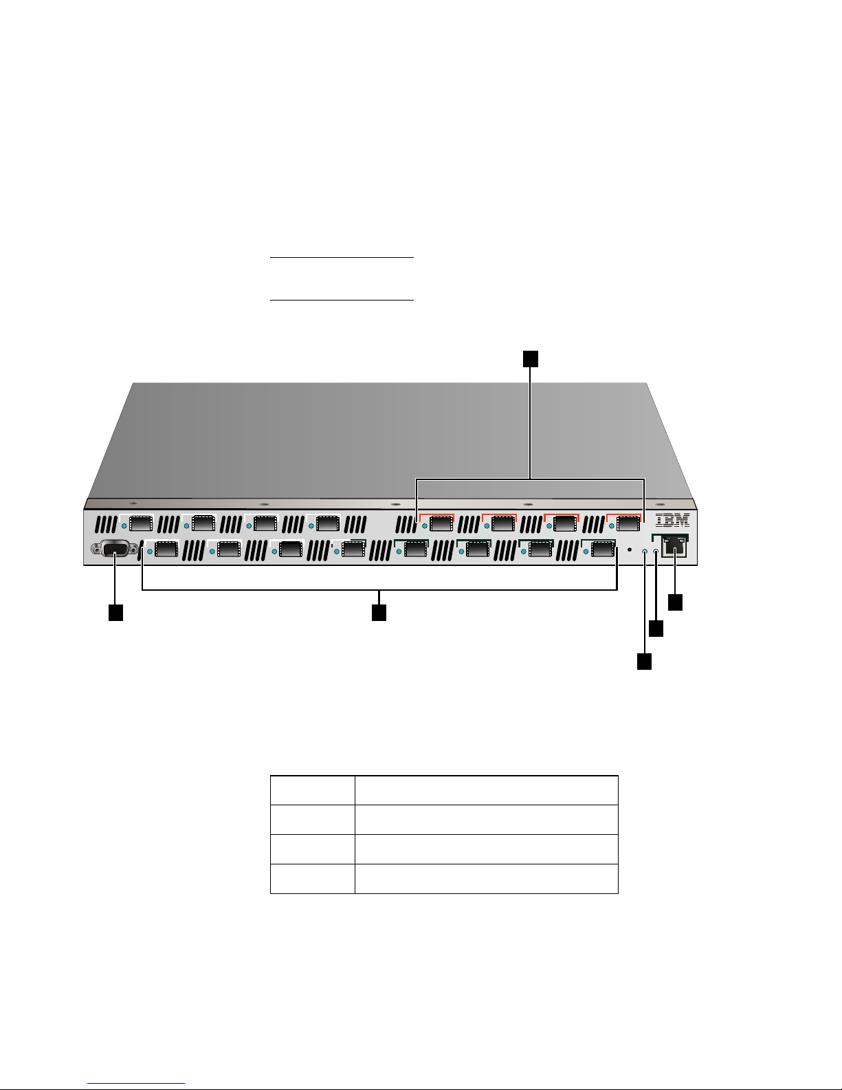
49
Chapter 3: Maintenance and troubleshooting
connections and port locations and shown in Figure 13, Physical
connections and ports.
If you purchased the SAN Router from a reseller, for further
assistance, contact your IBM representative.
NOTE: Troubleshooting the SAN Router requires that you have access to the
CLI and Element Manager to locate errors and resolve the errors
Figure 13 Physical connections and ports
9 12
11
10
1
3
2
4
5
7
6 8
13
15
14 16
SYS
10/100
CONSOLE
i2640002
2
1
3
4
6
5
Tabl e 19 Physical connections and port locations
Location Description
1 Management Port (RS-232 Serial)
2 FC Ports 1-12, FC 1 or 2 Gbps, GE 1 Gbps
3 Intelligent ports 13-16, iSCSI or iFCP
Page 74
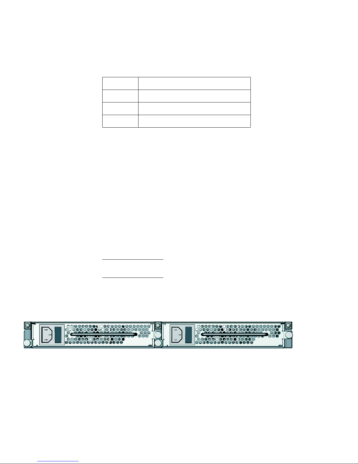
SAN16M-R SAN Router Installation And Service Manual
50
SAN Router physical connections
All ports and connectors are located on the front of the SAN Router,
as described in the following paragraphs. The rear of the SAN Router
contains only cooling fans, which are not accessible. The Field
Replaceable Units (FRUs) are the Fibre Channel Port transceivers and
power supplies which include fans.
Power
connections
There are two standard power connections located on the rear of the
SAN Router, one at each end. Each of these power connections
supplies AC power to a different power supply for power
redundancy and backup. Either power supply can support the SAN
Router operation, but it is recommended that both be connected, each
to a different power source to maintain redundancy.
NOTE: If a power supply is not connected, an error message will be
generated.
The two power supplies, located on the rear of the SAN Router are
FRUs (see Figure 14). To remove a power supply, review Chapter 5,
RRP 2: Redundant power supply.
Figure 14 Power supply FRUs
Fibre channel
ports
There are twelve user-configurable fibre channel ports located on the
front of the SAN Router, labeled 1 through 12. These port connections
accommodate standard fibre channel transceivers and SFP
4 System status LED
5 Management por t status LED
6 Manage port (RJ-45) 10/100
Table 19 Physical connections and port locations
Location Description
i2640003
Page 75

51
Chapter 3: Maintenance and troubleshooting
connectors. These ports provide 2Gbps connectivity and can be
configured as:
•FC_Auto (default)
•FL_Port
•F_Port
• L_Port
• R_Port
Intelligent
Ethernet ports for
IP connection
There are four user-configurable intelligent IP ports located on the
front of the SAN Router, labeled 13 through 16. Each of these ports
has a connector, for 1 Gbps SFP connection. Each intelligent port can
be configured for either Internet Small Computer Systems Interface
(iSCSI), or Internet Fibre Channel Protocol (iFCP).
Management ports There are two management ports located on the front of the SAN
Router. An RS-232 serial port that can be connected to a VT100 or
terminal emulator for access to the Command Line Interface (CLI),
and RJ45 port that can be connected to the LAN for Out-of-Band
management using the SAN Router Element Manager. The RJ45
management port can be accessed by any PC on the LAN with a web
browser.
Page 76

SAN16M-R SAN Router Installation And Service Manual
52
SAN Router LEDs
Table 20 lists and describes the LEDs for the SAN Router.
NOTE: In the Meaning column below, link means the Ethernet link is
detected, that is, the cable is plugged in and connected to an Ethernet port at
the other end. Initialized means the software has loaded all the necessary
routines and the SAN Router is operational.
Table 20 LEDs on the SAN Router
LED label Color Meaning
Sys Green and amber The LED is a dual-color (green/amber) LED.
During startup, the LED is amber and blinks rapidly on and off.
During normal operation, the LED is green and blinks slowly on and
off when power is flowing to the SAN Router.
The LED is off when there is no power to the SAN Router.
Errors, such as power outage, can also be viewed through the
Element Manager or SANvergence Manager. Refer to Accessing
SNMP alerts or alarms for information on determining problems
Error None There is no LED for errors. Errors are available from the System Log
or via SNMP alerts. Errors can also be viewed through the Element
Manager or SANvergence Manager.
Power supply None There are no LEDs for the power supplies. Refer to Accessing SNMP
alerts or alarms for information on determining if a power supply has
failed.
FC/GE port LED (Ports 1
through 12)
Green/amber This LED is a dual-color (green/amber) LED. Green stands for GE,
amber stands for FC. Both colors blink with traffic; the rate of blinking
indicates the amount of traffic. If the LEDs are off, there may be a
broken link or the port hardware may not be working. (If the port is
not being used, the LED will be off.)
Errors can also be viewed through the Element Manager or
SANvergence Manager. Refer to Accessing SNMP alerts or alarms
for information on determining problem.
Page 77

53
Chapter 3: Maintenance and troubleshooting
SAN Router troubleshooting
Review Table 21, to help troubleshoot SAN Router problems,
including configuration problems, through the Element Manager.
NOTE: Detailed troubleshooting information is available in the
Administration and Configuration Manual.
iFCP/iSCSI port LEDs
(Ports 13 through 16)
Green Intelligent ports, speed 1 Gbps, variable with software settings. Solid
green indicates a link is detected.
Blinking means traffic; the rate of blinking increases with the amount
of traffic. If the LED is off, there may be a broken link.
Errors can also be viewed through the Element Manager or
SANvergence Manager. Refer to Accessing SNMP alerts or alarms
for information on determining problems.
Management port LED
(10/100)
Green This LED stays on while power is on but does not indicate a link. The
LED blinks when there is traffic.
Errors can also be viewed through the Element Manager or
SANvergence Manager. Refer to Accessing SNMP alerts or alarms
for information on determining problems.
Tabl e 20 LEDs on the SAN Router (Continued)
LED label Color Meaning
Tabl e 21 SAN Router troubleshooting summary
Problem Meaning and solution
A yellow border appears around one of
the ports on the Element Manager device
view.
This usually indicates that the port is not properly configured or the port has been
disabled.
• The GE ports may display yellow if you initially configured the SAN Router without
IP address entries for these ports. You must configure one or the other with an IP
address, using CLI or Element Manager.
• In Element Manager, make sure that you have appropriate IP address entries for
the Management IP Address and the GE port(s).
• If you made any changes or additions to the IP configuration, choose Save
Configuration from the File menu, then also choose Reset System from the File
menu.
• Be sure to save any open applications and quit any operations currently running on
the SAN Router prior to rebooting.
Page 78

SAN16M-R SAN Router Installation And Service Manual
54
There is a red outline around one of the
ports on the Element Manager device
view.
This usually indicates that the connection is down for that particular port.
• The GE ports may display red if the cable is not plugged in securely. Check both to
make sure that they have clicked into place.
• Check cables for dents and tears, and make sure no large or sharp objects are on
top of the cables (especially the GE cable).
You cannot download firmware when the
management port has an IP address of
224.x.x.x or above
IP addresses of 224.x.x.x and above are Class D or Class E addresses that are
specifically reserved for multicast addresses or for future use. Set the SAN Router
manager port IP address below 224.x.x.x to solve the problem.
You see the following error message:
WARNING: IP ADDRESS IS 0, PLEASE
SET IP ADDRESS AND RESET
The SAN Router does not yet have a valid inband IP address. Use the Inband Address
Configuration dialog box (Configuration >System >Inband Address) to set the inband
address.
You are not able to download firmware
using Element Manager.
• A TFTP server must be running on a server that the SAN Router can connect to
through either the management port or a GE port. The TFTP protocol is not FTP.
• File names and paths are critical. Try to move the firmware to the same directory
on the servers where the TFTP server is located and use the name of the file with
the new path in the dialog box. The path that you enter in Element Manager is
always relative to the TFTP server's root directory.
• Try pinging the IP address of the management port for out-of-band management or
the SAN Router Inband IP address for inband management from the TFTP server
(example: ping 192.168.2.170).
After setting up your iFCP configuration,
you can’t see your remote devices.
• Check both iFCP ports and make sure you have link lights between the port and
the SAN Router/GE switch on either side. Ping across the link from local to the
remote SAN Router.
• Check in the Element Manager to make sure that each SAN Router has a unique
mSAN ID (Configuration>iFCP>Setup) and that the SAN Router has been reset
since this was changed.
• Check in the Element Manager to make sure that the iFCP port IP addresses are
on the same subnet or that the next hop router address is the correct next
hop/gateway.
• Check in the Element Manager to make sure that the Zone IDs are the same for the
mutually exported zones (Configuration>iFCP>Remote Connections).
• Check in the Element Manager to make sure that the remote SAN Router status is
up by going to: Configuration>iFCP>Remote Connections and checking the Status
column for the SAN Router in question. It should say “Up.”
Table 21 SAN Router troubleshooting summary (Continued)
Problem Meaning and solution
Page 79

55
Chapter 3: Maintenance and troubleshooting
The operating system is not seeing my
attached storage devices.
• Normally there is a problem with the connection, the interface, the zoning, port type
or the drivers when the devices are not being recognized.
Check the front panel of the SAN Router or use Element Manager to make sure
the port type is set correctly for each port. Refer to the SAN Router’s
Administration and Configuration Manual for more details.
Ensure that the transmit and receive optical lines are not reversed such that the
transmitters are connected to each other.
If you have SANvergence Manager. Select one of the SAN Routers in the
SANvergence Manager window and select mSAN Configuration to display the
mSAN Configuration window. Make sure the proper devices are listed and that
they are in a common zone. If you need to make zone configuration changes,
be sure to commit the changes and save them to flash memory in the SAN
Router.
Verify that the cables being used are intact and of good quality.
You aren’t sure which Fibre Channel port
type to assign.
Fibre Channel port parameters that you can configure through the FC/Ethernet Port
Configuration dialog box in the Element Manager include:
• FC Auto - Ports that automatically sense whether the type of connection is F_Port
or FL_Port. Use FC-Auto for connecting Fibre Channel devices such as host bus
adapters and storage targets. This will negotiate either arbitrated loop or
point-to-point connections with the connected devices.
• F_Port - A port to which non-loop N_Ports are attached.
• FL_Port - A port to which one or more NL_Ports in an arbitrated loop are attached.
• L_Port - Private loop or filer mode. In this mode, the port will come up in loop mode
without requesting devices to do FLOGI; in other words, the connecting device is
forced to be a private device. Most NAS filers need the port to be configured in this
mode.
• R_Port - a fabric extension port used to establish inter-switch links (ISLs) between
a SAN Routers and FC switches. R_Ports allows you to interconnect, zone, and
manage existing fabrics with mSANs. R_Port is an added-cost option; it is not
available in the basic SAN Router software package. Use R_port to establish
inter-switch links (ISLs) between FC switches and Eclipse SAN Routers. R-Port
allows you to interconnect, zone and manage existing fabrics with mSANs.
You don’t know whether to set your Fibre
Channel devices to Arbitrated Loop or
Point-to-Point.
The SAN Router will support either arbitrated loop or point-to-point. Certain host bus
adapter drivers or firmware have preferred modes in which they will try to negotiate
one topology and revert to the other if that is not available. This is an unreliable method
therefore we recommend you set your devices to point-to-point or arbitrated loop only
mode.
Tabl e 21 SAN Router troubleshooting summary (Continued)
Problem Meaning and solution
Page 80

SAN16M-R SAN Router Installation And Service Manual
56
GE port troubleshooting
Table 22 GE port problems and solutions
Problem Solution
Only one of your GE ports is showing
activity.
• Check that the GE cable is securely inserted in both the SAN Router and the
Gigabit Ethernet port on the SAN Router
• Make sure that the Gigabit Ethernet cable is not damaged and that nothing sharp
or heavy has been placed directly on it (this may damage the delicate fiber of the
cable).
• Check that the RX and TX connectors are correct on the cable (the individual
connectors may need to be switched around to correct the signal).
• Try another cable.
• Make sure that the cable doesn't have any kinks in it and that it is not damaged.
You need to know how to use In-Band
management.
You can manage the SAN Router through the Gigabit Ethernet interface. The IP
address to use in SANVergence Manager is the SAN Router’s in-band IP address.
In-band management is only supported on a Gigabit Ethernet port set to Gigabit
Ethernet port, not Gigabit Ethernet trunk port or COS ports.
Ethernet frames are being dropped. • A GE switch with mFCP links between the SAN Router in the same cluster
must
have IEEE 802.3x symmetric flow control enabled to both send and receive pause
frames. Refer to the documentation for your GE switch vendor for further
information. GE SAN Routers in an iFCP or iSCIL link do not require 802.3x flow
control.
• Check to ensure you have GE rated SFPs. Fibre Channel rated SFPs will not
function properly with GE.
• Physical problems such as dirty optical connections, damaged cables or sheaths or
damaged SFPs will cause intermittent communication errors.
• Consider rate limiting.
You need to know which GE port type to
select on the SAN Router.
The GE port is the most basic port type. If you are going to use in-band management,
at least one port on the SAN Router must be set to this mode. GE trunk ports use a
trunking protocol to aggregate two or more links to a supported GE switch. COS mode
enables a class of service function that is supported by some products.
Page 81

57
Chapter 3: Maintenance and troubleshooting
Serial Management Console troubleshooting
Review Table 23, Serial Management Console troubleshooting to help
troubleshoot problems with the console connected to the
management port.
Retrieving the system log
The System Log (different from the Element Manager Message Log)
contains errors or warning states encountered at the SAN Router.
This could include ports going up and down, mSNS unable to zone, a
SAN Router task failing, and so on.
The System Log is a fixed size. New entries are written to the
beginning of the log overwriting the oldest entries. The log may be
cleared out from time to time, so it is important to remember that the
log may not include every error.
Tabl e 23 Serial Management Console troubleshooting
Problem Solution
The Serial Management Console will not
come up.
There are several reasons that you may not be able to bring up a console connected to
the serial port. Make sure the “null modem” cable on the management workstation is
plugged in securely to the proper serial port.
Check that the settings for the VT100 terminal emulator are correct. The default
settings are:
• Baud Rate: 9600
•Data Bits: 8
• Parity: None
• Stop Bits: 1
• Flow Control: None
Make sure that you have selected the proper COM port for the emulator and that the
Serial port is enabled in the system BIOS (check with your computer manufacturer for
more information on this).
The characters on the Serial
Management Console screen are
garbled.
This is typically caused by a configuration problem with the VT100 emulator terminal:
Go to the advanced settings for the terminal and make sure that the VT100 terminal
emulation setting is set to ANSI or auto detect.
There are strange messages on my
screen.
There are different occasions during loading sequences or operation where messages
may appear, but if they continue to appear for no apparent reason, or if you have
further questions, contact Customer Support for further assistance.
Page 82

SAN16M-R SAN Router Installation And Service Manual
58
To upload the System Log from the SAN Router to the management
workstation, follow these instructions:
1. Select File>System Log>Retrieve to display the Retrieve System Log
dialog box (Figure 15 on page 58).
Figure 15 Retrieve the system log dialog box
2. Type the IP address where the management workstation TFTP
server resides.
3. Type or modify the name of the file where you want this segment
of the log stored. For some TFTP servers, if you are creating a new
file, you must place it in an existing subdirectory.
4. Click the Retrieve button.
5. Click OK to empty the System Log.
Accessing SNMP alerts or alarms
The SAN Router sends SNMP traps (alerts or alarms) to designated
IP addresses (workstations) where the alerts or alarms can be viewed.
In order to receive SNMP alerts, the SAN Router must be configured
to enable SNMP traps (alerts or alarms). Review the Administration
and Configuration Manual for information on configuring SNMP traps.
The SNMP traps are configured to be routed to specific workstations
based on IP address. The data from the SNMP alerts can be viewed
from Element Manager and SANvergence Manager. Also, there is a
utility called the TrapViewer that is shipped with SANvergence
Manager you can use to view the SNMP alerts or alarms.
i2640011
Page 83

59
Chapter 3: Maintenance and troubleshooting
Table 24, SNMP alerts or alarm definitions provides a list of SNMP
alerts or alarms that are useful in resolving hardware errors (this is
not a complete list, review the Administration and Configuration
Manual for a complete list of all SNMP alerts):
Tabl e 24 SNMP alerts or alarm definitions
Figure 16, Power supply alert shown in trap viewer shows the Trap
Viewer utility which is shipped with Sanvergence manager.
Alert or alarm name Description
Cold Start The SAN Router is powered on, or rebooted. Informational only message, no action
required.
Link Down A port interface loses an active link signal.
Link Up A port interface acquires an active link signal.
flashNewImageInstallTrap A new firmware image is installed in flash memory. Informational only message, no
action required.
envVoltageUpperThreshTrap The upper voltage threshold is exceeded. This message indicates that there may be a
problem with the power supplies or the router.
envVoltageLowerThreshTrap The power voltage is less than the lower voltage threshold. This message indicates
that there may be a problem with the power supplies or the router.
envTempUpperTrap The upper temperature threshold is exceeded. This message indicates that there may
be a problem with the power supplies or the router.
ChasFanStatusTrap The state of the fan changes. This message indicates there may be a problem with
the power supplies (the fans are part of the power supply units.)
ChasPowerSupplyStatusTrap The status of power changes from down to up or vice versa. This message indicates
there is a problem with a power supply.
connUnitPortStatus Change The overall status of a port that has changed. This message indicates there may be a
problem with a port or a link is no longer active.
connUnitStatusChange The overall status of the SAN Router that has changed.
Page 84

SAN16M-R SAN Router Installation And Service Manual
60
Figure 16 Power supply alert shown in trap viewer
Performing a loopback test
If you suspect there is a hardware problem with a port, you can insert
the loopback connector, which is supplied with the router, into the
port to determine if the port is operating correctly. If the LED turns
solid when the loopback connector is plugged into the port, then the
port hardware is operating correctly. If the LED does not turn solid,
then review the Administration and Configuration Manual for
additional troubleshooting procedures.
NOTE: The loopback connector works only with Ethernet ports; not FC
ports. In order to test a port, you would need to change the port from FC to
Ethernet, then test the port. If you do this, the router will need to be reset for
changes to take effect. After you complete the test, you will need to
reconfigure the FC ports.
Other resources for troubleshooting
In addition to the previous troubleshooting information, there are
additional resources that can be used in the troubleshooting process.
i2640012
Page 85

61
Chapter 3: Maintenance and troubleshooting
SANvergence Manager
The SANvergence Manager provides the following tools which can
used in the troubleshooting process:
• Configuration archive provides information which includes:
system log, and SAN Reports.
• Log Viewer which can be used to view the system log.
• Statistical reports which can help resolve performance issues as
well as
Review the Administration and Configuration Manual for more
information including performing troubleshooting using
SANvergence Manager.
E/OSi CLI
The CLI can be used with these commands: mgt, stats, port config as
well as other commands. Review the E/OSi Command Line Interface for
IBM TotalStorage Products User Manual.
Element Manager
The Element Manager can be used to view the status of ports as well
as hardware status of the SAN Router. In addition, you can view the
message log for errors. Review the Administration and Configuration
Manual for more information on how to use Element Manager to
troubleshoot both hardware and software problems.
Cleaning fiber-optic components
Perform this procedure as directed in this publication and when
connecting or disconnecting fiber-optic cables from port optical
transceivers (if necessary). To clean fiber-optic components:
1. Obtain the appropriate tools (portable can of oil-free compressed
air and alcohol pads) from the fiber-optic cleaning kit.
2. Disconnect the fiber-optic cable from the transceiver. Use
compressed air to blow any contaminants from the connector as
described below and shown in Figure 17, Clean fiber-optic
components).
— Keep the air nozzle approximately 50 millimeters (two inches)
from the end of the connector and hold the can upright.
Page 86

SAN16M-R SAN Router Installation And Service Manual
62
— Blow compressed air on the surfaces and end of the connector
continuously for approximately five seconds.
Figure 17 Clean fiber-optic components
3. Gently wipe the end-face (1) and other surfaces of the connector
with an alcohol pad as shown in (2) of Figure 17. Ensure the pad
makes full contact with the surface to be cleaned. Wait
approximately five seconds for cleaned surfaces to dry.
4. Repeat step 2 and step 3 of this procedure (second cleaning) and
again (third cleaning), then reconnect the fiber-optic cable to the
port.
1 2
i12M1072
Page 87

© Copyright IBM Corp. 2007
63
Chapter 4: Parts catalog
Use the links below to access the major topics in this chapter.
Parts catalog
This chapter provides an illustrated parts breakdown or part
numbers for field-replaceable units (FRUs).
• Front-accessible FRUs.
• Rear-accessible FRUs.
• Miscellaneous parts.
• Power cords and receptacles.
The parts lists also include part numbers, descriptions, and
quantities.
RoHS information
European Parliament Directive 2002/95/EC takes effect July 1, 2006
restricting the use of certain hazardous substances in electrical and
electronic equipment (RoHS). Equipment placed on the market
before that date is exempt from RoHS regulations. The use of
non-RoHS parts for repair and replacement is permitted for
non-RoHS equipment. Equipment placed on the market after that
date must comply with RoHS regulations, including the requirement
that all repairs and replacements must use parts that are RoHS
compliant
Section Page
Parts catalog 63
Front-accessible FRUs 64
Rear-accessible FRUs 64
Miscellaneous parts 65
Power cords and receptacles 66
Page 88

SAN16M-R SAN Router Installation And Service Manual
64
When ordering spare parts, you must install RoHS compliant parts in
any unit that contains a serial number that ends with the letter R. For
example, if the serial number is 130000R, then that unit contains
RoHS compliant parts and any replacement part must be RoHS
compliant.
NOTE: A part in a non-RoHS compliant unit (serial number not ending in an
alpha character) can be replaced by either a non-RoHS compliant or a RoHS
compliant part.
Front-accessible FRUs
Table 25, FRU List-front accessible lists the FRU part numbers,
descriptions, and quantities.
Table 25 FRU List-front accessible
Rear-accessible FRUs
Table 26, FRU List-rear accessible lists the FRU part numbers,
descriptions, and quantities.
Table 26 FRU List-rear accessible
Non-RoHS part numbers RoHS part numbers Description
22R3944 23R0675 Base assembly
Reference only Reference only Long wave optical transceiver, 35 KM
Reference only Reference only Long wave optical transceiver, 10KM
Reference only Reference only Shortwave optical transceiver
Non-RoHS part number RoHS part numbers Description Qty.
22R3944 23R0675 Base assembly NA
22R3945 23R0676 Power supply (250 W, 90-264 VAC In, 24V out)
includes internal fan.
2
Page 89

65
Chapter 4: Parts catalog
Miscellaneous parts
Figure 18 illustrates miscellaneous parts. Table 27 is the associated
parts list. The table includes reference numbers to Figure 18, part
numbers, descriptions, and quantities.
Figure 18 Miscellaneous parts
1 2 3
i12M1082
Tabl e 27 Miscellaneous Parts List
Key Part number Description
1 Reference only Plug, loopback, LC connector
2 Reference only Cable, null modem, DB9F-DB9F
connector, 10 feet
3 Reference only Cable, Ethernet, 10 feet
Page 90
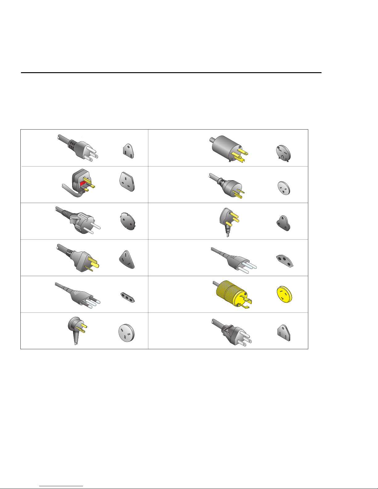
SAN16M-R SAN Router Installation And Service Manual
66
Power cords and receptacles
Figure 19 illustrates optional power cords and receptacles. The
associated parts list is on page 67. The table includes reference
numbers to Figure 19, feature numbers, and descriptions.
Figure 19 Power cords
1
2
3
4
5
6
7, 11,15
9
10
8
12, 13,14
16
i12M1083
Page 91

67
Chapter 4: Parts catalog
Tabl e 28 Power cord part number list
Key Part number Description
1 Reference Only Power cord, AC, North America
NEMA 5-15P straight, 125 volts, 10 amps, 3.0 meters
Receptacle: NEMA 5-15R
2 Reference Only Power cord, AC, United Kingdom
BS 1363 right angle, 250 volts, 10 amps, 2.8 meters
Receptacle: BS 1363
3 Reference Only Power cord, AC, European Community
CEE 7/7 straight, 250 volts, 10 amps, 2.5 meters
Receptacle: CEE 7
4 Reference Only Power cord, AC, Australia
AS 3112 straight, 250 volts, 10 amps, 2.8 meters
Receptacle: AS 3112
5 Reference Only Power cord, AC, Italy, Chile, Libya, and Ethiopia
CEI 23-16/VII straight, 250 volts, 10 amps, 2.8 meters
Receptacle: CEI 23-16/VII
6 Reference Only Power cord, AC, Israel
SI-32 right angle, 250 volts, 15 amps, 2.8 meters
Receptacle: SI-32
7 Reference Only Power cord, AC, Thailand, Philippines, Taiwan, Bolivia, and Peru
NEMA 6-15P straight, 250 volts, 15 amps, 2.8 meters
Receptacle: NEMA 6-15R
8 Reference Only Power cord, AC, Denmark
Afsnit 107-2-D1 straight, 250 volts, 10 amps, 2.8 meters
Receptacle: Afsnit 107-2-D1
9 Reference Only Power cord, AC, South Africa, Burma, Pakistan, India, and Bangladesh
BS 546 Type, right angle, 250 volts, 15 amps, 2.8 meters
Receptacle: BS 546
10 Reference Only Power cord, AC, Switzerland and Liechtenstein
SEV 1011 straight, 250 volts, 10 amps, 2.8 meters
Receptacle: SEV 1011
Page 92

SAN16M-R SAN Router Installation And Service Manual
68
11 Reference Only Power cord, AC, United States (Chicago)
NEMA 6-15P straight, non-locking, 250 volts, 10 amps, 1.8 meters
Receptacle: NEMA 6-15R
12 Reference Only Power cord, AC, United States (Chicago)
NEMA L6-15P straight, twist-lock, 250 volts, 10 amps, 1.8 meters
Receptacle: NEMA L6-15R
13 Reference Only Power cord, AC, North America
NEMA L6-15P straight, twist-lock, 250 volts, 10 amps, 2.8 meters
Receptacle: NEMA L6-15R
14 Reference Only Power cord, AC, North America
NEMA L6-15P straight, twist-lock, 250 volts, 10 amps, 2.8 meters
Receptacle: NEMA L6-15R
15 Reference Only Power cord, AC, Japan
NEMA 6-15P straight, 250 volts, 10 amps, 2.8 meters
Receptacle: NEMA 6-15R
16 Reference Only Power cord, AC, Japan
JIS 8303 straight, 125 volts, 12 amps, 2.5 meters
Receptacle: NEMA 5-15R
Not
Shown
Reference Only Power cord, AC, 20V/10 A for cabinet installation
Table 28 Power cord part number list (Continued)
Key Part number Description
Page 93

© Copyright IBM Corp. 2007
69
Chapter 5: Removal and replacement procedures
Use the links below to access the major topics in this chapter.
Procedural notes
The following procedural notes are referenced in applicable removal
and replacement procedures.
1. Before removing a FRU, read the removal and replacement
procedures for that FRU carefully and thoroughly to familiarize
yourself with the procedures and reduce the possibility of
problems or customer down time.
2. After completing steps of a detailed procedure that is referenced
from another procedure, return to the initial (referencing)
procedure and continue to the next step of that procedure.
3. After completing a replacement procedure, clear any error
messages reporting the failure and any message reporting the
recovery from the Element Manager or SANvergence Manager
and extinguish the system error (SYS) light-emitting diode (LED)
at the front panel.
RRP 1: SFP optical transceiver
Small form factor pluggable (SFP) optical transceivers are removed
and replaced while the router is powered on and operational.
Use the following procedures to remove or replace an SFP optical
transceiver from the front of the router chassis. Refer to Chapter 4,
Parts catalog, for FRU locations and part numbers.
Section Page
Procedural notes 69
RRP 1: SFP optical transceiver 69
RRP 2: Redundant power supply 72
Page 94

SAN16M-R SAN Router Installation And Service Manual
70
Tools required The following tools are required to perform these procedures.
• Door key with 5/16-inch socket (only for some equipment
cabinets).
• Protective cap (provided with the fiber-optic jumper cable).
• Loopback plug connector (provided with the router).
• Fiber-optic cleaning kit.
CAUTION
Data processing environments can contain equipment transmitting
on system links with laser modules that operate at greater than
Class 1 power levels. For this reason, never look into the end of an
optical fiber cable or open receptacle.
(C027)
Removal To remove an SFP optical transceiver:
1. Notify the customer that the port with the defective transceiver
will be blocked. Ensure the customer’s system administrator sets
the attached device offline.
2. If the router is installed as part of a stand-alone configuration,
go to step 3. If the router is rack-mounted, perform one of the
following:
— If the router is installed in an equipment cabinet, if necessary,
insert the 5/16-inch door tool into the socket hole at the right
top of the front door. Turn the tool counter-clockwise to
unlock and open the door.
— If the router is installed in a customer-supplied equipment
cabinet, unlock and open the cabinet front door as directed by
the customer representative.
3. Identify the defective port transceiver by:
— Viewing the LED adjacent to the port.
— Viewing SNMP alerts or alarms or port status from the
Element Manager or SANvergence Manage.
— Performing a loopback test. See Performing a loopback test on
page 60.
Page 95

71
Chapter 5: Removal and replacement procedures
4. Block communication to the port.
5. Disconnect the fiber-optic jumper cable from the port:
a. Pull the keyed LC connector free from the port’s optical
transceiver.
b. Place a protective cap over the jumper cable connector.
6. The optical transceiver has a wire locking bale to secure the
transceiver in the port receptacle and to assist in removal. The
locking bale rotates up or down, depending on the transceiver
manufacturer and port location.
a. Disengage the locking mechanism by rotating the wire locking
bale up or down 90 degrees.
Replacement To replace an SFP optical transceiver:
1. Remove the replacement transceiver from its packaging.
2. Insert the transceiver into the port receptacle, then engage the
locking mechanism by rotating the wire locking bale up or down
90 degrees.
3. Perform an external loopback test on the port. See Performing a
loopback test on page 60.
4. Reconnect the fiber-optic jumper cable:
a. Remove the protective cap from the cable connector and the
protective plug from the port’s optical transceiver. Store the cap
and plug in a suitable location for safekeeping.
b. Clean the jumper cable and transceiver connectors. Refer to
Cleaning fiber-optic components on page 61 for instructions.
c. Insert the keyed LC cable connector into the port’s optical
transceiver.
5. Activate the port to restore communications.
6. Ensure the LED adjacent to the port transceiver is off.
7. Review in either Element Manager or SANvergence Manager to
verify the error has been corrected.
Page 96

SAN16M-R SAN Router Installation And Service Manual
72
RRP 2: Redundant power supply
Use the following procedures to remove or replace a redundant
power supply (with internal cooling fan) from the rear of the router
chassis.
Tools required If installed in a cabinet center, a door key is required to perform these
procedures.
Removal To remove a redundant power supply:
1. If the router is installed as part of a stand-alone configuration,
skip this step. If the router is rack-mounted and installed in a
cabinet, open the cabinet front door.
2. Review in either Element Manager or SANvergence Manager to
verify the error which is reported as an SNMP alert or alarm. The
error message which include which power supply has failed.
3. Disconnect the AC power cord from the power supply you are
removing.
DANGER
Multiple power cords
(L003)
4. Remove the power supply by unscrewing the thumb screws.
5. Pull the power supply out by the handles as shown in Figure 20,
Power supply removal.
Page 97

73
Chapter 5: Removal and replacement procedures
Figure 20 Power supply removal
Replacement To replace a redundant power supply:
1. Remove the replacement power supply from its shipping
container.
2. Inspect the rear of the power supply for bent or broken connector
pins that may have been damaged during shipping. If any pins
are damaged, obtain a new power supply.
3. Position the power supply in the rear of the router. While
supporting the power supply with one hand, insert it into the
router chassis.
4. Tighten the thumb screws.
5. Connect the AC power cord to the power supply and to a facility
power source.
6. Review in either Element Manager or SANvergence Manager to
verify the error has been cleared.
7. If installed in a cabinet, close the equipment cabinet door.
i2640013
Page 98

SAN16M-R SAN Router Installation And Service Manual
74
Page 99

© Copyright IBM Corp. 2007
75
Appendix A: Specifications
Use the links below to access the major topics in this appendix.
Port characteristics
•12 FC ports.
• 4 GE/TCP ports.
• Management port: 1 10/100 (RJ-45).
• Management port: RS-232 Serial.
Size and weight
• Height: 42.2 mm (1.66 in) or 1 rack unit.
• Width: 429.3mm (16.90 in).
• Depth: 645.8 (25.425 in).
• Weight: 11.4 kg (25 lbs).
Power requirements
• U.S./Japan: Nominal 100/120 volts, 50 to 60 Hz.
Section Page
Port characteristics 75
Size and weight 75
Power requirements 75
Power consumption 76
Environmental requirements 76
Compatible transceivers 76
Page 100

SAN16M-R SAN Router Installation And Service Manual
76
• Europe/Australia: Nominal 220/240 volts, 50 to 60 Hz
Power consumption
• Dual redundant power supplies, each with a maximum power
consumption of 250 Watts for the SAN Router.
• Power consumption: 190 Watts.
Environmental requirements
• Temperature: 5° to 40° C (41° to 104° F).
• Humidity: 20% to 85% non-condensing.
• Heat output: 650 BTU/hr.
Compatible transceivers
The following information regarding compatible transceiver modules
applies to the SAN Router except where specified.
1G FC multi-mode, LC connectors
• Agilent Technologies - HFBR-5701L - 1G Fibre Channel
100-M5-SN-1/100-M6-SN-1 (Multi-Mode, LC Connector)
Transceivers
• Agilent Technologies - HFBR-5701LP - 1G Fibre Channel
100-M5-SN-1/100-M6-SN-1 (Multi-Mode, LC Connector)
Transceivers
• JDS Uniphase - JSP-21S0AA1 -1G Fibre Channel
100-M5-SN-1/100-M6-SN-1 (Multi-Mode, LC Connector)
Transceivers
• JDS Uniphase - JSM-21S3AAP - 1G Fibre Channel
100-M5-SN-1/100-M6-SN-1 (Multi-Mode, LC Connector)
Transceivers
• PicoLight - PL-XPL-00-S23-71 - 1G Fibre Channel
100-M5-SN-1/100-M6-SN-1 (Multi-Mode, LC Connector)
Transceivers
 Loading...