

Page 1

Hardware Maintenance Manual
IBM PC Server/Enterprise Racks
IBM
Page 2

Page 3

Hardware Maintenance Manual
IBM PC Server/Enterprise Racks
IBM
Page 4

Note:
Before using this info rm atio n and the produ ct it supp or ts , be sure to read th e gen era l
information under “Notices” on page 195.
Sixth Edition (November 1999) Updated April 2001
The following paragraph does not apply to the United Kingdom or any country where such provisi ons are
incons istent with local law :
INTERNATIONAL BUSINESS MACHINES CORPORATION PROVIDES THIS PUBLICATION "AS IS" WITHOUT
WARRANTY OF ANY KIND, EITHER EXPRESS OR IMPLIED, INCLUDING, BUT NOT LIMITED TO, THE IMPLIED
WARRANTIES OF MERCHANTABILITY OR FITNESS FOR A PARTICULAR PURPOSE. Some states do not allow
disclaimer of express or implied warranties in certain transactio ns, th erefore, this statement may not apply to you.
This publication could include technical inaccuracies or typographical errors. Changes are periodically made to the
information herein; these changes will be incorporated in new editions of the publication. IBM may make improvements
and/or changes in the product(s) and/or the program( s) described in this publication at any time.
This publication was developed for products and services offered in the United States of America. IBM may not offer the
products, services, or features discussed in this document in other countries, and the information is subject to change
without notice. Consult your local IBM representative for information on the products, services, and features available in
your area.
Requests for technical information about IBM products sho uld be made to your IBM reseller or IBM marketing
representative.
© Copyright International Business Machines C orporation 2001. All rights reserved.
US Government Users Restricted Rights – Use, duplication or disclosure restricted by GSA ADP Schedule Contract with
IBM Corp.
Page 5

About this supplement
This supplement contains diagnostic and service information for the IBM PC Server
Rack Enclosure and the IBM Rack enclosures:
IBM PC Ser ver Rack Encl osure models:
• Type 9306 19-inch and 24-inch Models:
— 4QS, 4QX, 9QS
— 9QX, 9TS, 9TX
• IBM Rack enclosure models:
— Type 9306 Models 200, 900
— Type 9308 Models 42P, 42X, 42S, 42E, 4SA, 4SB (NetBAY42 Enterprise)
• IBM NetBAY3 enclosure
• IBM NetBAY3E enclosure
This supplement should be used with the related service information in the IBM PC
Servers Hardwar e Ma intenance Manual (part number 70H0751, form number S30H2501-01).
Important: This manual is intended for trained servicers who are familiar with IBM
PC Server and IBM Server products.
Before servicing an IBM product, be sure to review “Safety info rma tion”
on page 183.
Related publicat ion s
The following publications are available for IBM products. For more information,
contact IBM or an IBM Author ized Dealer.
© Copyright IBM Corp. 2001 iii
Page 6

For information about See publication
PC Servers IBM PC Servers Hardware Maintenance Manual
(S30H-2501)
PS/2 Computers IBM Personal System/2 Hardware Maintenance
Manual (S52G-9971)
PS/ValuePoint Compute r s IBM PS/ValuePoint Hardware Maintenance Service
and Refere nce (S61G-1423)
Laptop, Notebook, Portable, and
ThinkPad Computers (L40 , CL57, N45,
N51, P70/P 75, ThinkPad 300, 350, 500,
510, 710T, Expansi on Unit, Dock I,
Dock II)
ThinkPad Computers (Thi nkPad 340,
355, 360, 370, 700, 701, 720, 750, 755)
ThinkPad Computers (Thi nkPad 365,
760)
Monitors (Disp l ays ) (February 199 3) IBM PS/2 Display HMM Volume 1 (SA38-0053 )
Monitors (December 1993) IBM Color Monitor HMM Volume 2 (S71G-4197)
IBM Monitors (P Series) (February
1996)
IBM 2248 Monitor (February 1996) IBM Monitor HMM Volume 4 (S52H-3739)
Disk Array technology overview and
using the IBM RAID Configuration
Program
Installation Planning for Personal
System/2 computers
Ins tallati on Plan n i ng f o r A dvanc e d
Personal System/2 Servers
IBM Mobile Systems Hardware Maintenance
Manual Volume 1 (S82G-1501)
IBM Mobile Systems Hardware Maintenance
Manual Volume 2 (S82G-1502)
IBM Mobile Systems Hardware Maintenance
Manual Volume 3 (S82G-1503)
IBM Monitor HMM Volume 3 (S52H-3679)
Configuring Your Disk Array booklet (S82G-1506)
Personal Sy s tem/2 Installation Planning and
Beyond (G41G-2927)
Advanced PS/2 Servers Planning and Selection
Guide (GG24-3927)
iv Hardware Maintenance Manual: IBM PC Server/Enterprise Racks
Page 7

Contents
About this supplement . . . . . . . . . . . . . . . iii
Related publications . . . . . . . . . . . . . . . . . . . . . . . . . . . . . . iii
IBM PC Server/Enterprise rack enclosures1
General checkout. . . . . . . . . . . . . . . . . . . . . . . . . . . . . . . . . 1
Power checkout . . . . . . . . . . . . . . . . . . . . . . . . . . . . . . . . . . 2
Powering off the rack . . . . . . . . . . . . . . . . . . . . . . . . . . . . . 3
Type 9306 Models 4QS, 4QX, 9Q S, 9QX,
9TS, 9TX . . . . . . . . . . . . . . . . . . . . . . . . . . . 5
Features. . . . . . . . . . . . . . . . . . . . . . . . . . . . . . . . . . . . . . . . . 5
IBM PC Server expansion rack models. . . . . . . . . . . . 5
Locations. . . . . . . . . . . . . . . . . . . . . . . . . . . . . . . . . . . . . . . . 5
Server selector console . . . . . . . . . . . . . . . . . . . . . . . . . 6
Server selector unit . . . . . . . . . . . . . . . . . . . . . . . . . . . . 6
Connections . . . . . . . . . . . . . . . . . . . . . . . . . . . . . . . . . . 7
Power distribution unit . . . . . . . . . . . . . . . . . . . . . . . . . 7
Cooling fan . . . . . . . . . . . . . . . . . . . . . . . . . . . . . . . . . . . 8
Sliding trays . . . . . . . . . . . . . . . . . . . . . . . . . . . . . . . . . . 9
Sliding rails . . . . . . . . . . . . . . . . . . . . . . . . . . . . . . . . . . 10
Keyboard tray. . . . . . . . . . . . . . . . . . . . . . . . . . . . . . . . 11
Parts list i ng (Type 9306 – 19-inch) Model s 9QS, 9TS and
9QX, 9TX. . . . . . . . . . . . . . . . . . . . . . . . . . . . . . . . . . . . . . . 12
Parts list i ng (Type 9306 – 24-inch) M odels 4QS, 4QX . 17
Type 9306 Model 200 . . . . . . . . . . . . . . . . . 21
Features. . . . . . . . . . . . . . . . . . . . . . . . . . . . . . . . . . . . . . . . 21
Locations. . . . . . . . . . . . . . . . . . . . . . . . . . . . . . . . . . . . . . . 21
Side panel . . . . . . . . . . . . . . . . . . . . . . . . . . . . . . . . . . . 21
Selector switch locations. . . . . . . . . . . . . . . . . . . . . . . 22
Power Distribution Unit . . . . . . . . . . . . . . . . . . . . . . . 26
Blank bezel . . . . . . . . . . . . . . . . . . . . . . . . . . . . . . . . . . 27
Fixed shelf . . . . . . . . . . . . . . . . . . . . . . . . . . . . . . . . . . . 27
Keyboard tray. . . . . . . . . . . . . . . . . . . . . . . . . . . . . . . . 28
Installing a flat panel monitor rack mount kit. . . . . 29
Removing the existing flat panel monitor stand. . . 29
Installing the new monitor stand. . . . . . . . . . . . . . . . 31
Starting the system. . . . . . . . . . . . . . . . . . . . . . . . . . . . 35
Configuring the selector switch . . . . . . . . . . . . . . . . . 35
Switching among servers . . . . . . . . . . . . . . . . . . . . . . 36
Advanced selector switch functions . . . . . . . . . . . . . 37
Resetting the selector switch . . . . . . . . . . . . . . . . . . . 45
Making connections under power. . . . . . . . . . . . . . . 46
Parts Listing (Type 9306 Model 200). . . . . . . . . . . . . . . . 47
Attaching rack cabinets in a suite . . . . . . . . . . . . . . . 92
Installing L-channel support rails to rack mounting
brackets . . . . . . . . . . . . . . . . . . . . . . . . . . . . . . . . . . . . . . . . 94
Installing a server . . . . . . . . . . . . . . . . . . . . . . . . . . . . 97
Fixed shelf . . . . . . . . . . . . . . . . . . . . . . . . . . . . . . . . . . 100
Keyboard tray . . . . . . . . . . . . . . . . . . . . . . . . . . . . . . . 101
Monitor shelf. . . . . . . . . . . . . . . . . . . . . . . . . . . . . . . . 102
Installing a flat panel monitor rack mount kit. . . . 103
Removing the existing flat panel monitor stand. . 103
Installing the new monitor stand. . . . . . . . . . . . . . . 105
Blank filler panel . . . . . . . . . . . . . . . . . . . . . . . . . . . . 109
Parts listing (Type 9308 Model 42P, 42X) . . . . . . . . . . . 111
NetBAY3 enclosure . . . . . . . . . . . . . . . . . 115
Features . . . . . . . . . . . . . . . . . . . . . . . . . . . . . . . . . . . . . . . 1 15
Locations. . . . . . . . . . . . . . . . . . . . . . . . . . . . . . . . . . . . . . 115
Casters . . . . . . . . . . . . . . . . . . . . . . . . . . . . . . . . . . . . . 116
Foot pads . . . . . . . . . . . . . . . . . . . . . . . . . . . . . . . . . . . 116
Front cover . . . . . . . . . . . . . . . . . . . . . . . . . . . . . . . . . 117
Rear panel . . . . . . . . . . . . . . . . . . . . . . . . . . . . . . . . . . 117
Device side rails . . . . . . . . . . . . . . . . . . . . . . . . . . . . . 118
Stacking NetBAY3 enclosures. . . . . . . . . . . . . . . . . . 118
Parts Listing (NetBAY3) . . . . . . . . . . . . . . . . . . . . . . . . . 121
NetBAY3E enclosure . . . . . . . . . . . . . . . . 123
Features . . . . . . . . . . . . . . . . . . . . . . . . . . . . . . . . . . . . . . . 123
Locations. . . . . . . . . . . . . . . . . . . . . . . . . . . . . . . . . . . . . . 123
Casters . . . . . . . . . . . . . . . . . . . . . . . . . . . . . . . . . . . . . 124
Front cover . . . . . . . . . . . . . . . . . . . . . . . . . . . . . . . . . 124
Rear panel . . . . . . . . . . . . . . . . . . . . . . . . . . . . . . . . . . 125
Device side rails . . . . . . . . . . . . . . . . . . . . . . . . . . . . . 126
Stacking NetBAY3E enclosures . . . . . . . . . . . . . . . . 126
Parts listing (NetBAY3E). . . . . . . . . . . . . . . . . . . . . . . . . 127
IBM NetBAY console switch . . . . . . . . . . 129
Features . . . . . . . . . . . . . . . . . . . . . . . . . . . . . . . . . . . . . . . 130
Tool requirements . . . . . . . . . . . . . . . . . . . . . . . . . . . . . . 131
Specifications . . . . . . . . . . . . . . . . . . . . . . . . . . . . . . . . . . 132
Installation overview . . . . . . . . . . . . . . . . . . . . . . . . . . . 132
Installing a console switch in a monitor shelf . . . . 132
Installing a console switch vertically in a rack. . . . 134
Installing a console switch horizontally in a rack . 137
Parts listing (NetBAY Console Switch). . . . . . . . . . . . . 139
Type 9306 Model 900/910 . . . . . . . . . . . . . 51
Features. . . . . . . . . . . . . . . . . . . . . . . . . . . . . . . . . . . . . . . . 51
Locations . . . . . . . . . . . . . . . . . . . . . . . . . . . . . . . . . . . . 51
Parts listing (Type 9306 Model 900/910) . . . . . . . . . . . . 77
NetBAY 42 Enterprise Rack (Type 9308
Models 42P, 42X, 4SA, 4SB, 42S, 42E). . 81
Features. . . . . . . . . . . . . . . . . . . . . . . . . . . . . . . . . . . . . . . . 81
Locations. . . . . . . . . . . . . . . . . . . . . . . . . . . . . . . . . . . . . . . 85
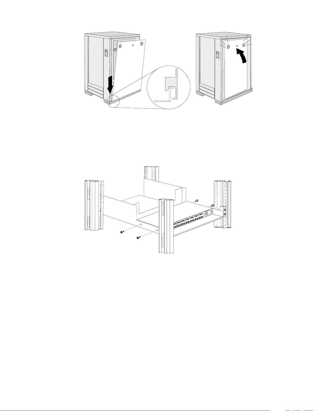
Removing and installing panels . . . . . . . . . . . . . . . . 85
Doors . . . . . . . . . . . . . . . . . . . . . . . . . . . . . . . . . . . . . . . 87
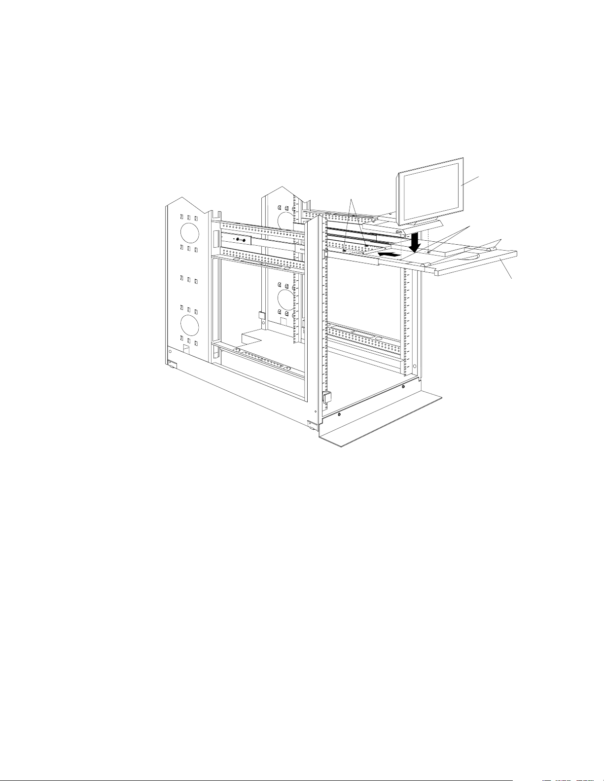
Removing and installing the top 6U portion of t he rack
91
Installing the stabilizer bracket . . . . . . . . . . . . . . . . . 92
© Copyright IBM Corp. 2001 v
NetBAY Power Distribution Units. . . . . . 141
NetBAY rack Power Distribution Unit introduction . 141
Tool requirements. . . . . . . . . . . . . . . . . . . . . . . . . . . . 142
Installation overview . . . . . . . . . . . . . . . . . . . . . . . . . 142
Installing devices vertically . . . . . . . . . . . . . . . . . . . 142
Installing a single device horizontally . . . . . . . . . . 144
Installing two devices horizontally . . . . . . . . . . . . . 146
Cabling your PDUs . . . . . . . . . . . . . . . . . . . . . . . . . . 148
NetBAY front-end Power Distribution Unit introduction.
156
Tool requirements. . . . . . . . . . . . . . . . . . . . . . . . . . . . 157
Installation overview . . . . . . . . . . . . . . . . . . . . . . . . . 157
Installing a single device vertically . . . . . . . . . . . . . 157
Installing two devices vertically . . . . . . . . . . . . . . . 160
Rack PDU specifications . . . . . . . . . . . . . . . . . . . . . . 164
Page 8

Line cords . . . . . . . . . . . . . . . . . . . . . . . . . . . . . . . . . . 165
Power cables . . . . . . . . . . . . . . . . . . . . . . . . . . . . . . . . 165
NetBAY server dual-cord Power Distribution Unit
introduction . . . . . . . . . . . . . . . . . . . . . . . . . . . . . . . . . . . 166
Tool requirements . . . . . . . . . . . . . . . . . . . . . . . . . . . 167
Installation overview. . . . . . . . . . . . . . . . . . . . . . . . . 167
Installing devices vertically . . . . . . . . . . . . . . . . . . . 167
Installing a single device horizontally . . . . . . . . . . 169
Installing two devices horizontally. . . . . . . . . . . . . 171
Cabling your PDUs . . . . . . . . . . . . . . . . . . . . . . . . . . 173
Power cables . . . . . . . . . . . . . . . . . . . . . . . . . . . . . . . . 180
Line cords . . . . . . . . . . . . . . . . . . . . . . . . . . . . . . . . . . 181
Parts listing (Power Distribution Units) . . . . . . . . . . . 181
Related service information . . . . . . . . . . 183
Safety information. . . . . . . . . . . . . . . . . . . . . . . . . . . . . . 183
Safety notice (multi-lingual translations) . . . . . . . . 191
Safety inspection guide . . . . . . . . . . . . . . . . . . . . . . . 192
Handling electrostatic dischar ge-sensitive devices 193
Grounding requirements. . . . . . . . . . . . . . . . . . . . . . 194
Problem determination tips . . . . . . . . . . . . . . . . . . . . . . 194
Notices. . . . . . . . . . . . . . . . . . . . . . . . . . . . . . . . . . . . . . . . 195
Send us your comments! . . . . . . . . . . . . . . . . . . . . . . . . 196
Trademarks. . . . . . . . . . . . . . . . . . . . . . . . . . . . . . . . . . . . 197
vi Hardware Maintenance Manual: IBM PC Server/Enterprise Racks
Page 9

IBM PC Server/Enterprise rack encl osures
General checkout. . . . . . . . . . . . . . . . . . . . . . . . . . . . . 1
Power checkout . . . . . . . . . . . . . . . . . . . . . . . . . . . . . . 2
General checkout
Use the following procedur e for diagnosing keyboard, mouse, and video pr oblems for
the IBM PC Server Rack Enclosure and the IBM Rack enclosures (Type 9306 and Type
9308).
For power problems, see “Power checkout” on page 2.
Attention:
• For Models 4QS, 4QX, 9QS, 9QX, 9T S, 9TX only:
Ensure that the voltage se lector switch on each server installed in the server rack
is set to 230 V ac.
• For Models 200, 900 only:
Ensure that the voltage se lector switch on each server installed in the server rack
is set to the proper voltage as supplied by the Power Distribution Unit, PDU.
1. Check the foll owing:
• Ensure the external power cord is in good condition and properly connected
to a known-good power source.
• Ensure the internal power cables are in good condition and properly
connected. (The internal power cables connect between the power
distrib ution unit and the servers insta ll e d in the server rack.)
• Ensure the following devices are power ed on.
a. Power distribution unit
b. Server select or unit
c. All system units
d. Display
2. If the items/conditions specified in step 1. are not okay, correct the problem and
verify that the server rack is operating correctly.
3. If the items/conditions specified in step 1. are okay, then, using the server selector
keypad buttons, check the operation of the failing device for all of the servers that
are installed in the rack.
4. Did the failure occur on more than one server?
• NO: Go to the Hardware Mai ntenance manual for the serv e r th at was
selected when the failure occurred. Disconnect the keyboard an d mouse from
the server selector unit and connect them directly to the failing server. Then,
run the server diagnostic programs on the failing server.
If the problem still remains, disconnect the keyboard and mouse from the
failing server and reconnect them to the server selector unit. Then, replace the
server rack components in the following order until the problem goes away.
a. Device cable (connects between the server selector unit and the server
that was selected when the failure occurred).
Powering off the rack. . . . . . . . . . . . . . . . . . . . . . . . . 3
© Copyright IBM Corp. 2001 1
Page 10

Power checkout
b. Server selector cable (connects between the server selector keypad and
the server selector unit).
c. Server selector keypad.
d. Server selector unit.
• YES: Power-off the server rack and replace the server rack components in the
following order until the probl em goes away. See “Powering off the rack” on
page 3.
a. Device extender cable (connects between the device and the server
selector unit)
b. Failing device
c. Server selector cable (connects between the server selector keypad and
the server selector unit)
d. Server selector keyp ad
e. Server selector unit
Use the following procedure for diagnosing power problems for the IBM PC Server
Rack Enclosure and IBM Rack enclosure (Type 9306).
Attention:
• For Models 4QS, 4QX, 9QS, 9QX, 9T S, 9TX only:
Ensure that the voltage se lector switch on each server installed in the server rack
is set to 230 V ac.
• For Models 200, 900 only:
Ensure that the voltage se lector switch on each server installed in the server rack
is set to the proper voltage as supplied by the Power Distribution Unit, PDU.
1. Check the foll owing:
• Ensure the external power cord is in good condition and properly connected
to a known-good power source.
• Ensure the internal power cables are in good condition and properly
connected. (The internal power cables connect between the power
distrib ution unit and the servers insta ll e d in the server rack.)
• Ensure the following devices are power ed on.
a. Power distribution unit
b. Server selector unit
c. All system units
d. Display
2. If the items/conditions in step 1. are not okay, correct the problem and verify
correct operation of the server rack.
3. If the items/conditions specified in step 1. are okay, then, using the server selector
keypad buttons, check for correct operatio n of all the serve rs installe d in the rack .
4. Did the failure occur on more than one server?
• No: Go to the Hardware Maintenan ce manual for the ser ver that was sel ected
when the failure occurred and run the server diagnostic programs. If the
problem still remains, replace the powe r distr ibut io n unit.
2 Hardware Maintenance Manual: IBM PC Server/Enterprise Racks
Page 11

• Yes: Power-off the server rack and replace the server rack components in the
Powering off the rack
Before performing service on the rack, follow this procedure to prevent personal
injury and to avoid damaging the rack and the installed servers.
To power-off the IBM PC Server Rack:
1. Shut down and power-off all installed servers.
2. Power-off the serve r selector unit.
3. If a UPS system is installed in the rack, power-off the UPS system.
4. Disconne ct p o wer from the IBM PC Server Rack.
• If the rack is plugged into a wall-mounted power supply, disconnect the
• If the power cord is wired directly into the installed location's power supply,
following order until the probl em goes away. See “Powering off the rack” on
page 3.
a. Power distribution uni t fuse.
b. Power distribution unit.
power cord plug from the wall socket.
open the rear door of t he rack cabinet and disconnect th e power plug from the
base of the p o we r distri b uti o n u ni t .
IBM PC Server/Enterprise rack enclosures 3
Page 12

4 Hardware Maintenance Manual: IBM PC Server/Enterprise Racks
Page 13

Type 9306 Models 4QS, 4QX, 9QS, 9QX, 9TS, 9TX
Features. . . . . . . . . . . . . . . . . . . . . . . . . . . . . . . . . . . . . 5
IBM PC Server expansion rack models . . . . . . . . . . 5
Locations. . . . . . . . . . . . . . . . . . . . . . . . . . . . . . . . . . . . 5
Server selector console . . . . . . . . . . . . . . . . . . . . . . . . 6
Server selector unit . . . . . . . . . . . . . . . . . . . . . . . . . . . 6
Connections . . . . . . . . . . . . . . . . . . . . . . . . . . . . . . . . . 7
Power distribution unit . . . . . . . . . . . . . . . . . . . . . . . 7
Cooling fan. . . . . . . . . . . . . . . . . . . . . . . . . . . . . . . . . . 8
Sliding trays . . . . . . . . . . . . . . . . . . . . . . . . . . . . . . . . . 9
Features
The 9306 IBM PC Server Rack E nclosure, models 4QS, 9QS, 9TS come i n thr ee primary
models.
• 19-inch Quad Primary Server Rack, Model 9QS
• 19-inch Tri Primary Server Rack, Mode l 9TS
• 24-inch Quad Primary Server Rack, Model 4QS
A Quad Primary Server Rack can house up to four IBM PC Servers. The Tri Primary
Server Rack can house up to three IBM PC Servers.
Both Quad and Tri Primary Server Racks provide a built in serv er selec tor wh ich
connects to one set of cons ole devices (moni tor , keyboard, and mouse.) The se rver
selector works independently from the server's operating systems, enabling the
connected servers to run different operating systems.
Single latch rail tray . . . . . . . . . . . . . . . . . . . . . . . . . . 9
Dual latch rail tray . . . . . . . . . . . . . . . . . . . . . . . . . . 10
Sliding rails . . . . . . . . . . . . . . . . . . . . . . . . . . . . . . . . 10
Keyboard tray . . . . . . . . . . . . . . . . . . . . . . . . . . . . . . .11
Parts listing (Type 9306 – 19-inch) Models 9QS, 9TS
and 9QX, 9TX . . . . . . . . . . . . . . . . . . . . . . . . . . . . . . 12
Parts listing (Type 9306 – 24-inch) Models 4QS, 4QX
17
IBM PC Serv er expansio n rack models
Locations
These IBM 9306 PC Server Rack Enclosure models are shipped preassembled and precabled.
Three optional IBM PC Server Rack Expansion models are available to expand the
capacity of the IBM PC Server Rack Primary Enclosure. The optional IBM PC Server
Rack Expansion models are:
• 19-inch Quad Expansio n Rac k, Model 9Q X
• 19-inch Tri Expansion R ack, Mo del 9TX
• 24-inch Quad Expansio n Rac k, Model 4Q X
The IBM PC Server Rack Ex p ansion m od els allo w th e instal lation of u p to four more
servers using the Primary IBM PC Server Rack monitor, keyboard, and mouse.
The following sections contain information on specific equipment locations.
Note: For instructi ons on how to power-off the rack, see “Powering off the rack” on
page 3.
© Copyright IBM Corp. 2001 5
Page 14
Serve r sel ect or con so le
To remove the Server Selector Console:
1. Power-off th e rack.
2. Use an 1/8-inch allen wrench to remove screws.
3. Disconn e ct the server selector cable from the back of the server selector console.
4. Remove the server selector console from the cabinet.
Server
Monitor
Bezel
Selector
Console
Server
Selector
Keypad
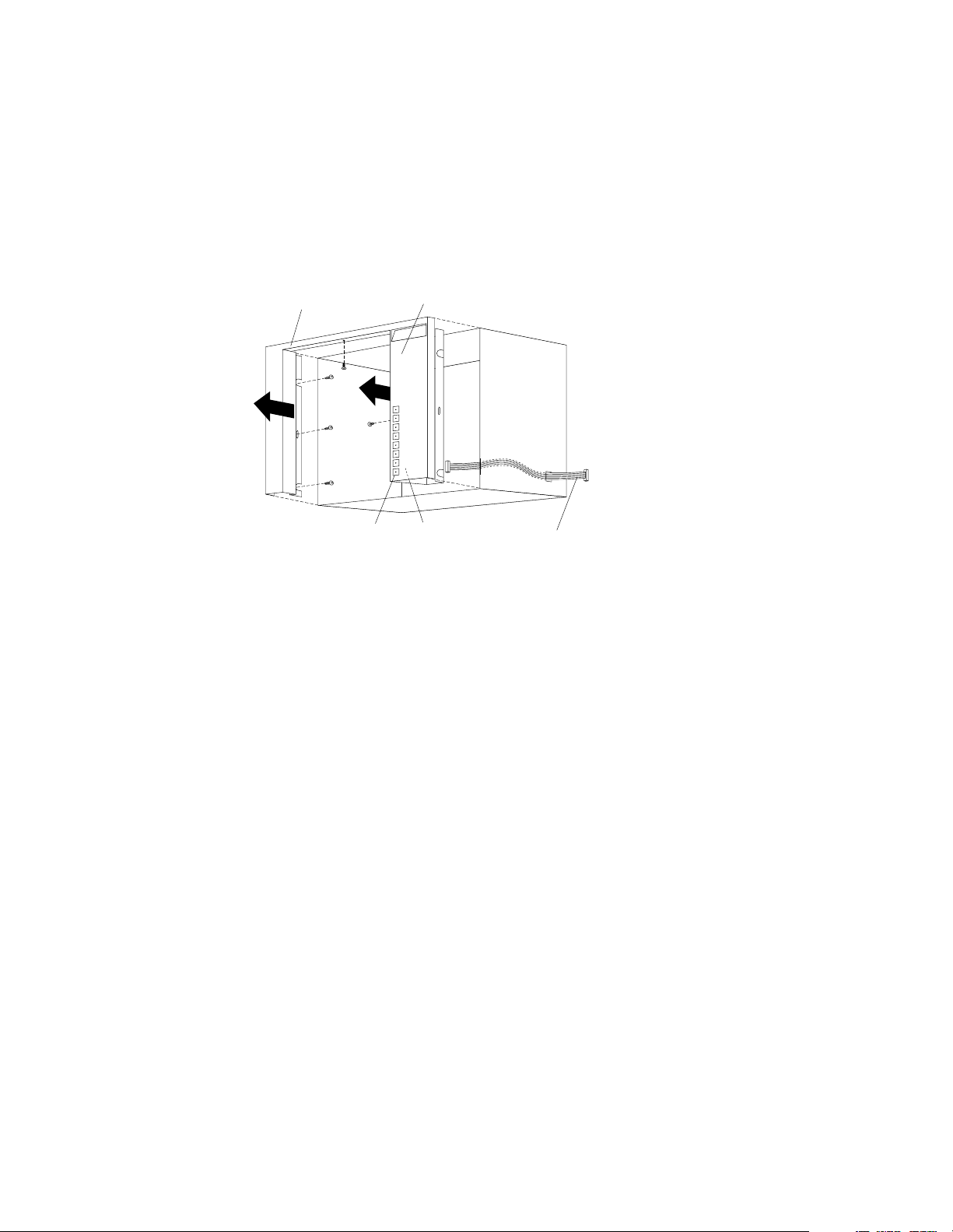
Serve r sel ect or un it
The server selector unit is located in the upper rear of the rack cabinet. The server
select or unit can only be acces s e d or remo v e d fro m the rea r of th e IB M Ra ck ca b in et.
CAUTION:
The server selector unit is heavy. You will need two people to safely remove the
server selector unit. See “Safety notice (multi-lingual translations)” on page 191.
To remove the server selector unit:
1. Power-off th e rack.
2. Unplug the keyboard, mouse, video cables, and the power cord.
3. Remove the ser ve r selector console.
4. With one person brac ing the server se lector unit f rom below, have the second
person use a 5/16-inch wrench to remove the four nuts that secure the server
selector unit to the rack cabinet.
5. Remove the server selector unit from the cabinet.
Note: When replac ing the ser ver sel ector unit , be sure t hat t he Server Sel ector ca ble is
fed throu gh the indentation along the lef t side of the server selector uni t.
Server
Selector
Electronics
Server
Selector
Cable
6 Hardware Maintenance Manual: IBM PC Server/Enterprise Racks
Page 15
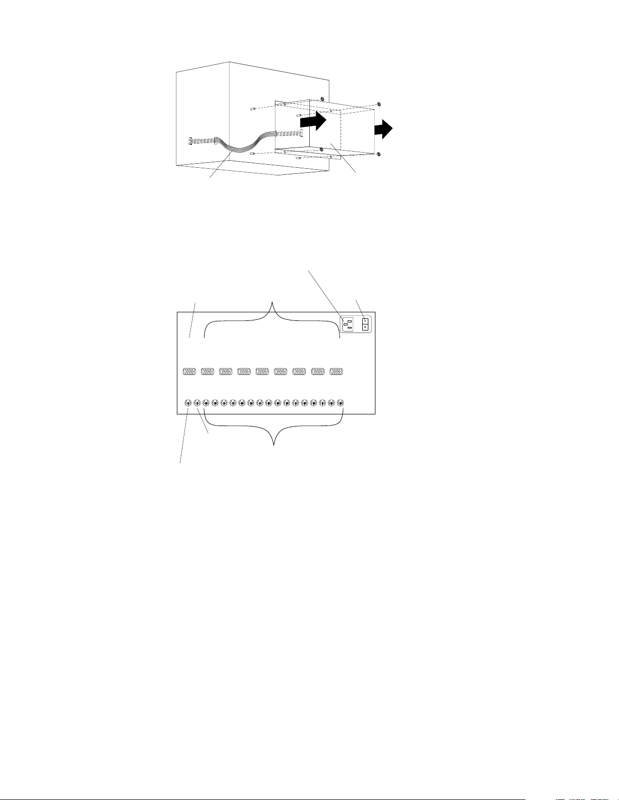
Server
Selector
Cable
Connections
Server Rack
Monitor
Connection
AC Power
Input
Server
Monitor
Connections
Server
Selector
Unit
Server Selector
Unit On-Off
Switch
M
O
N
O
K
B
O
Server Rack
Keyboard
Connection
G
G
A
A
2
1
M
K1M1K2M2K3M3K4M4K5M5K6M6K7M7K8M
O
U
Server Rack
Mouse
Connection
G
G
A
A
4
3
Server Keyboard
and Mouse
Connections
V
V
V
V
Power distributi on unit
Note: For information and installa tion instructi ons for the IBM NetBAY Rack Power
Distribu tion Units, see “Net BAY Power Distribution Units” on page 141".
Note: To remove the power distribution unit, you might need to remove the right
side cabinet panel, the server installed in sliding tray 2 (in the primary IBM PC
Server Rack), or sliding tray 5 (in the IBM PC Server Expansion Rack).
V
V
G
G
A
A
6
5
V
V
G
G
A
A
8
7
8
To remove the power distribution unit:
1. Power-off th e rack.
2. Disconnect all power plugs from the power distribution unit.
3. Using a Phillips screwdriver, remove the four screws from the front of the power
distrib u tion unit.
Type 9306 Mod els 4QS, 4QX, 9QS , 9Q X, 9TS, 9TX 7
Page 16
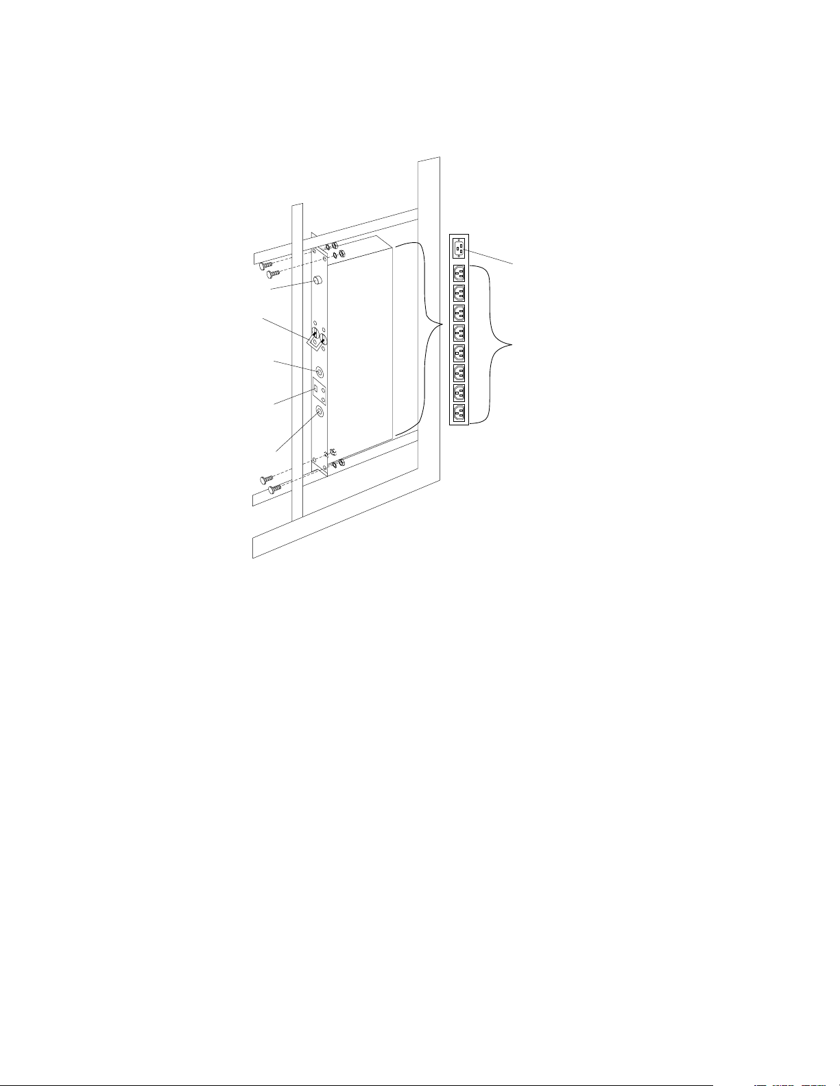
Note: These screws ar e held in place by nuts and washers. Hold the nut while
you are unscrewing the screw to prevent the nut and washer from falling
into the bottom of the cabinet.
4. Remove the po we r distribu tion unit from the cabinet.
AC Power
Input
AC Fuse
Circuit
Breaker
115V AC
Power-On
Indicator
Voltage
Selection
Switch
230V AC
Power-On
Indicator
AC Power
Output
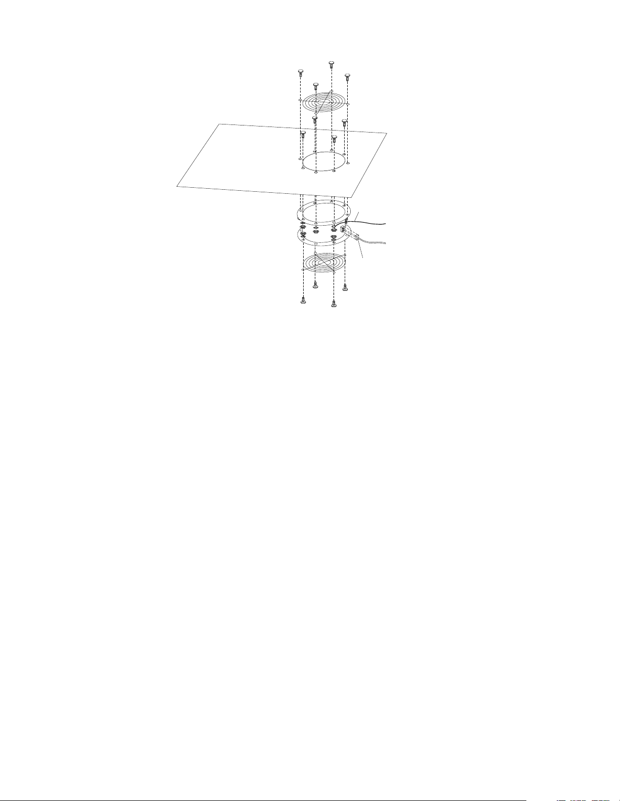
Cooling fan
To remove the cooling fan:
1. Power-off th e rack.
2. Open the rear door of the rack cab inet.
3. Disconnect the power plug from the rear of the cooling fan.
4. Use a 5/16-inch wrench to remove the eight nuts that secur e the cooling fan to the
top of the ra ck cabine t.
5. Remove the cooling fan from the cabinet.
Note: When installing the fan, make sure that the green and yellow ground wire is
attached to one of the top fan mounting screws and that the strain-relieving
clamp is attached to another. The power cable should be secured by the strainrelieving clamp.
8 Hardware Maintenance Manual: IBM PC Server/Enterprise Racks
Page 17
Sliding trays
Models 4QS and 4QX come with either single latch slide rails or dual latch slide rails.
Single latch slide rails have a front latch release on the right rail only. Dual latch slide
rails have a front latch release on both rails. The slide rail FRU number for the 24-inch
rack replaces the single latch slide rail with the dual latch slid e rail.
Note: If a server is installed on a tray being removed, first remove the server.
Single latch rail tray
To remove a sliding tray with single latch rails:
1. Power-off th e rack.
2. Open the rear door of the rack cabinet and remove the pin 1 that secures the
slidin g tr ay to the cable manage me nt arm
3. Loosen the thumbscrews 2 on the sliding tray and fully extend the sliding tray.
4. Use a 3/32-inch allen wrench to remove the five screws 3 from the left side of the
sliding tray.
5. Lift the rear locking tab 4 and push the sliding tray approximately two inches into
the cabinet.
6. Release the forward locking tab 5. Then, while holding the sliding tray in place,
use your other hand to grasp the outside sliding rail 6 and push it into the rack
cabinet until it disconnects from the sliding tray.
Ground
Wire
Power
Plug
Type 9306 Mod els 4QS, 4QX, 9QS , 9Q X, 9TS, 9TX 9
Page 18
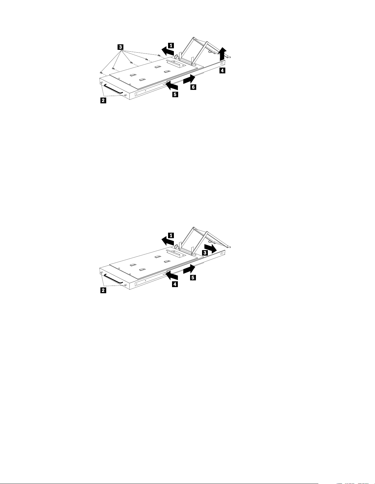
Dual latch rail tray
To remove a sliding tray with dual latch ra ils:
1. Power-off th e rack.
2. Open the rear door of the rack cabinet and remove the pin 1 that secures the
slidi ng tray to the cable managemen t arm.
3. Loosen the thumbscrews 2 on the sliding tray and fully extend the sliding tray.
4. Push in on the spring of the right rear locking tab 3 and push the sliding tray
approximately two inches into the cabinet.
5. Release both left and right forward locking tabs 4. Then, while holding the
sliding tray in place, push bo th left and righ t ou tside sli ding rails 5 into the rack
cabinet until it disconnects from the sliding tray.
Note: Left side view for 4 and 5 are not show n.
Sliding rails
This procedure is for single latch sliding rails and dual latch sliding rails.
For single latch sliding rails, the right rail is the one that has the front latch. The left
rail doe s n o t h a ve a fron t l a tc h .
For dual latch sliding rails, the right rail is the one that has the rear latch. The left rail
does not have a rear latch.
To remove the sliding rails:
1. Power-off th e rack.
2. Remove the sliding tray that is attached to the sliding rails that you want to
remove. See “Sliding trays” on page 9.
3. Use a 3/32-inch allen wrench to remove the four screws that secur e each of the
sliding rails to the rack cabin et.
10 Hardware Ma intena nce Manual: IBM PC Server/Enterprise Rack s
Page 19

Note: You will need to adjust the position of the sliding rail in order to line up the
access holes over the locations of the screws.
Keyboard tray
To remove the keyboard tray:
1. Power-off th e rack.
2. Disconnect the keyboard and mouse cables from the ke y board and mouse
extension cables.
3. Remove the keyboard and mouse from the keyboard tray.
4. Pu ll the keybo a rd tray straig ht out of the ra ck cabine t.
Type 9306 Mod els 4QS, 4QX, 9QS , 9Q X, 9TS, 9TX 11
Page 20
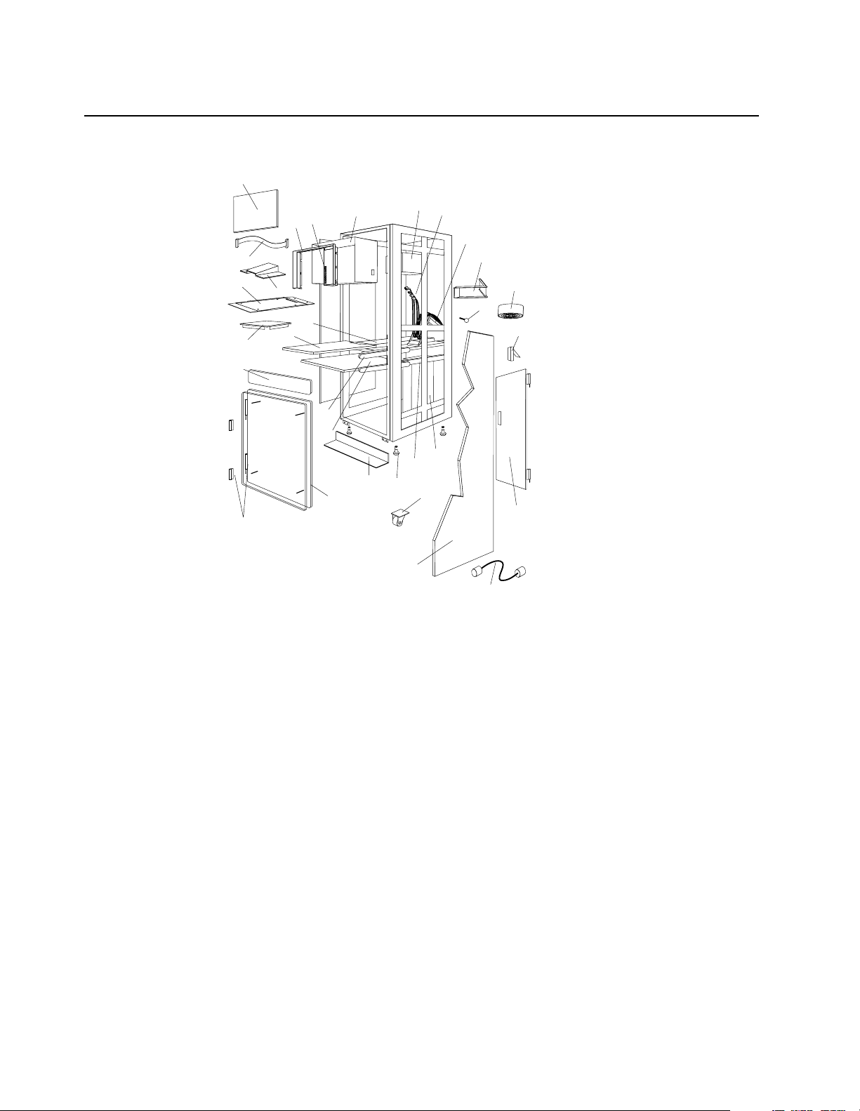
Parts listing (Type 9306 – 19-inch) Models 9QS, 9TS and 9QX, 9TX
This parts listi ng is for Models 9QS, 9TS and 9QX, 9TX
4
8
6
5
3
7
9
10
11
27
28
1
26
2
30
29
24
23
19
20
22
25
21
18
17
13
12
14
15
16
12 Hardware Ma intena nce Manual: IBM PC Server/Enterprise Rack s
Page 21

Index 19-Inch Rack Enclosure (Type 9306) FRU
1 Adapter Plate Options:
PS/2 Server 85 /95 76H3733
Model 300 76H3734
Model 500, 700 76H3734
2Monitor Stand 07H0061
3 Server Selector Cable 07H0036
4 Blank Bezel (9QX, 9TX Expansion units only) 76H0379
5 Monitor Bezel wit h button label 76H0378
6 Server Selector Keypad 07H0097
7 Monitor Housing (19-inch) 76H0377
8 Server Selector Unit Elect ronics
07H0034
See “Safety inspection guide” on page 192.
9 Internal Cables
06P6007
See Cable Kit Shelf Server
10 Cable Management Arm 76H0386
11 Cable Management Arm Single Server Tray 76H0387
12 Pin, Cable Manageme nt Arm 07H0089
13 Fan 220 V ac with Power Cord 07H0063
14 Latch, Rear Door 76H0376
15 Rear Door (19-Inch) 76H0373
15 Hinge Set for Rear Doo r 76H0389
16 External Powe r Cord:
Australia 14F1559
Europe 14F1554
Israel 14F1561
Italy 14F1560
New Zealand 14F1558
South America, India 14F1557
U.K./Denmark 14F1555
USA 14F1553
External Powe r Cord Option - 6 Ft. 07H0094
17 Left/Right Side Panel 76H0374
18 Caster 76H3626
19 NetBAY Rack Power Distribution Unit 09N9668
19 NetBAY Front-end Power Distribution Unit 09N9670
3-phase NEMA L21-30P line cord (200-250 Vac) for NetBAY Front-end PDU 00N7720
3-phase IEC 309 -3P+N+Gnd line co rd (380-415 Vac) for NetBAY Front-end PDU 00N7721
Type 9306 Mod els 4QS, 4QX, 9QS , 9Q X, 9TS, 9TX 13
Page 22

Index 19-Inch Rack Enclosure (Type 9306) FRU
1-phase NEMA L5-30P line cor d (100-127 Vac) for NetBAY Front-end PDU 00N7722
1-phase NEMA L6-30P line cor d (200-240 Vac) for NetBAY Front-end PDU 00N7723
1-phase IEC 309 -2P+Gnd line cord (200-240 Vac) for NetBAY Front-end PDU 00N7724
19 NetBAY Server Dual-cord Power Distribution Unit 09N9669
Hardware Kit for NetBAY Power Distri bution Units 09N9671
Power Distribution Unit 07H0424
19 250 V Slow Blow Fuse 0303549
20 Keyboard Sl ides, (one pair) 07H0038
21 Leveling Foot (Qty. 1) 76H0390
22 Stabilizing Bar 76H0375
23 Keyboard Tray, 19-Inch 76H0381
24 Slide Rails , Server Tray (one pair ) 07H0083
24 Slide Rails, Dual T r ay (one pair) 76H0383
25 19-inch Front Compartment Door (19-Inch by 26-Inch) Includes Hinge Set and Screws 76H0371
26 Door Hinge Set 76H0372
27 Door Valance (9QX, 9TX, Expansion units only) 76H0380
28 Mouse Table 07H0079
29 Dual Server Tray 76H0382
29 Dual Server Shelf 76H0385
30 Single Server Tray 76H0384
19-Inch Single Slide Shelf for an Industry Standard 19-Inch Rack. 76H3628
Cable, SVGA-Video (15 Feet) Opt i on 76H3736
Monitor Power Cabl e (connects from monitor to Power Dist ri bution Unit) 07H0075
Rack Keyboar d Cable (connects from Keyboard Drawer to Serv e r Sel e ctor Unit) 07H0067
Rack Mouse Cable (connects from Ke yboard Drawer to Serve r Se lector Unit) 07H0069
14 Hardware Ma intena nce Manual: IBM PC Server/Enterprise Rack s
Page 23

Rack Enclosure Kits (Type 9306) FRU
Bolt-Together Kit (19-Inch to 24- Inch, 24-Inch to 19- Inch)
• 19-Inch Attachment Bracket (2 each)
• Screw 1/4-20 x 1/2 Button Head Socket Cap Allen (8 each)
• Screw 1/4-20 x 1-1/4 Socke t Cap (4 each)
• Flanged Nut 1/4-20 (12 each)
• 24-Inch Attachment Bracket (4 each)
Cable Kit Shelf Server (12- foot cables)
• Monitor Cable
• Keyboard Cable
• Mouse Cable
• Internal Power Cable
Cable Kit Top Shel f Server (7-fo ot cables)
• Monitor Cable
• Keyboard Cable
• Mouse Cable
• Internal Power Cable
76G3627
06P6007
06P6006
Type 9306 Mod els 4QS, 4QX, 9QS , 9Q X, 9TS, 9TX 15
Page 24

Rack Enclosure Kits (Type 9306) FRU
Miscellaneous Parts Kit
• Rack Nut/Holder 10-32 (8 each)
• Keeper Nut 8-32 Zinc (8 each)
• Keeper Nut 10-32 (6 each)
• Screw 6-32 x 5/16 (2 each)
• Screw 6-32 x 1/4 Button Head Socket Cap Allen (8 each)
• Screw 10-32 x 3/8 Button Head Socket Cap (8 each)
• Screw 6-32 x 3/8 Button Head Socket Cap (2 each)
• Screw 1/4-20 x 1/2 Button Head Socket Cap (2 each )
• Screw 8-32 x 1/4 Button Head Socket Cap Allen (4 each)
• Screw 10-32 x 1/4 Button Head Socket Cap (2 each)
• Screw 8-32 x 1/4 Button Head Socket Cap (8 each)
• Pull-ring, 3-Inch (2 each)
• Shoulder Screw 8-32 x 3/8 (2 each)
• Standoff,.25 Hex, 6-32 FF,.5-Inch (2 eac h)
• Screw 8-32 x 3/8 Button Head Socket cap (2 each)
• Screw 10-24 x 1/4 Button Head Socket Allen (2 each)
• Screw 10-24 x 5/16 Button head Socket Allen (2 eac h)
• Keeper Nut 8-32 (2 each)
• Nut 8-32 (2 each)
• Captive Weld Nut (2 each)
• Whiz-Lock Flange Nut 1/4-20 (2 each)
• Keeper Nut 10-32 (2 each)
• Bumpers (2 each)
• C able Ties (8 each)
07H0057
Server Tray Interlock Kit
• Cam (1 each)
• Spring (1 each)
07H0091
16 Hardware Ma intena nce Manual: IBM PC Server/Enterprise Rack s
Page 25
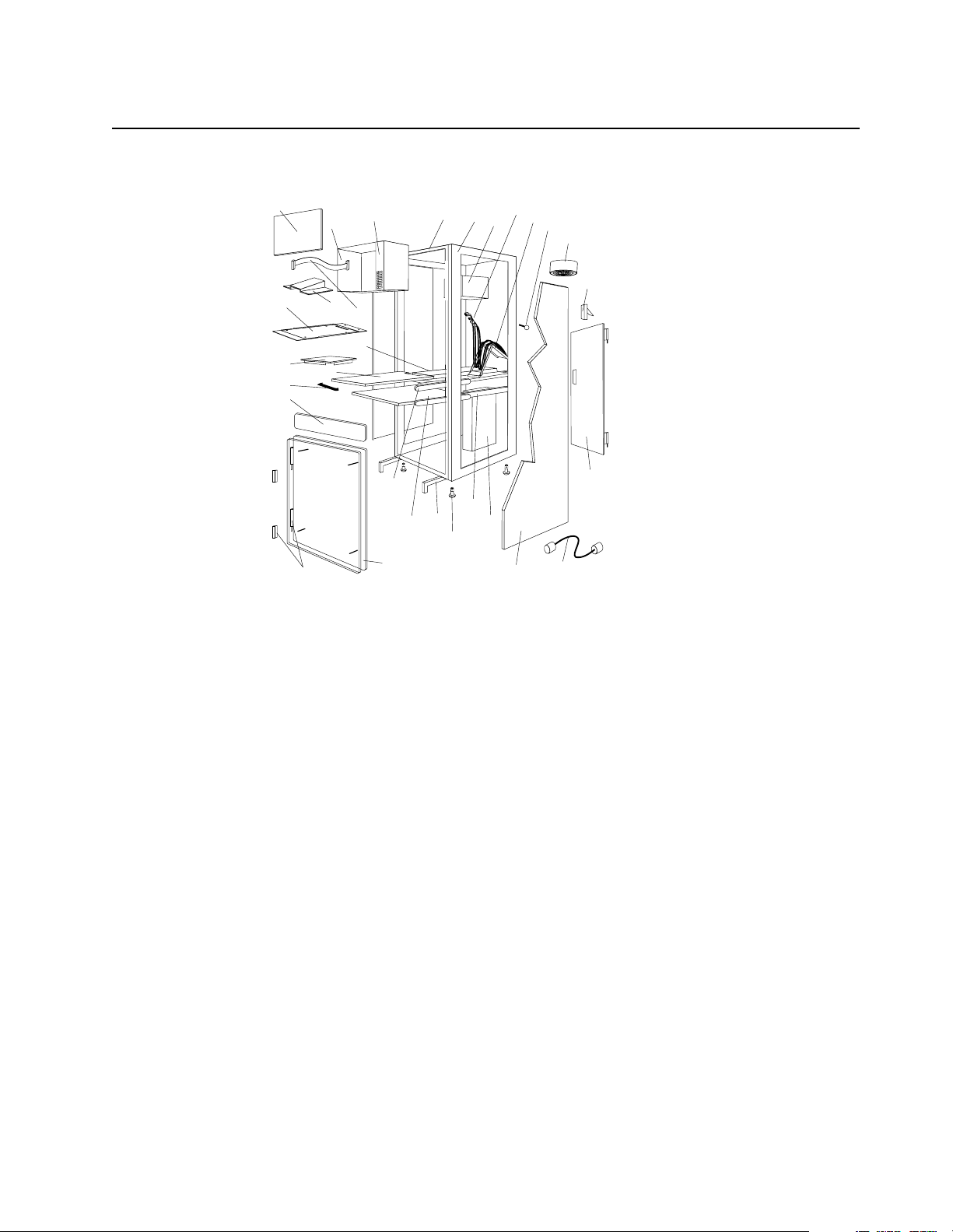
Parts listing (Type 9306 – 24-inch) Models 4QS, 4QX
This parts listing is for Models 4QS and 4QX.
4
29
27
26
6
5
1
28
2
3
30
7
10
8
11
9
12
13
14
25
23
24
22
21
20
19
18
17
15
16
Type 9306 Mod els 4QS, 4QX, 9QS , 9Q X, 9TS, 9TX 17
Page 26

Index 24-Inch Rack Enclosure (Type 9306) FRU
1 Adapter Plate Options:
PS/2 Server 85/95 76H3733
Model 300 76H3734
Model 500, 700 76H3735
2 Monitor Stand 07H0061
3Server Selector Cable 07H0036
4 Blank Bezel ( 4QX O nl y) 07H 0066
5 Monitor Housing (24-Inc h) 07H0065
6 Server Selector Keypad 07H0097
7 Rack Frame N/A
8 Spacer (see Spacer Kit, right side at end of this FRU list) 07H0059
9 Server Selector Unit Electronics See "Safet y Notice (Multi-lingual Translations) See “Safety
notice (multi-lingual translations)” on page 191.
10 Internal Cables (see Cable Kit Top Shelf Server and Cable Kit Bottom Shelf Server)
1 1 Cable Management Arm 07H0087
12 Pin, Cable Management Arm 07H0089
13 Fan 220 V ac with Power Cord 07H0063
14 Rear Door Latch/Lock with Key and Bracket 07H0055
15 Re ar D oo r (2 4 - I nc h ) 07H0047
16 Ex te r nal Powe r C ord :
Australia 14F1559
Europe 14F1554
Israel 14F1561
Italy 14F1560
New Zealand 14F1558
South A m e r i ca , In d i a 14F1557
U.K./Denmark 14F1555
USA 14F1553
External Power Co rd Option - 6 Ft. 07H0094
07H0034
17 Left/Right Side Panel 07H0049
18 NetBAY Rack Power Distributi on Unit 09N9668
18 NetBAY Front-end Power Distribution Unit 09N9670
18 NetBAY Server Dual-cord Power Distribution Unit 09N9669
Hard w a re Ki t for NetBAY Powe r Dist ri butio n Un i t s 09N9 671
18 Power Distribution Unit 07H0424
250 V Slow Blow Fuse 0303549
19 Keyboar d Slides, 24-I nch (one pair) 07H0038
18 Hardware Ma intena nce Manual: IBM PC Server/Enterprise Rack s
Page 27

Index 24-Inch Rack Enclosure (Type 9306) FRU
20 Leveling Feet (Qty. 4) 07H0053
21 Stabilizing Leg 07H0051
22 Keyboard Drawer , 24-Inch (wit h Sl id e s and Brackets) 07H0077
23 Slide Rails, Server Tray (one pair) 07H0083
24 24-Inch Front Compartme nt Door (24-Inch by 26-Inch) 07H0058
25 Door Hinge Se t 07H0045
26 Door Valance (4QX Only) 07H0068
27 Handle, Server/Keyboard Tray 07H0085
28 Server Tray 07H0081
29 Mouse Table 07H0079
30 Shelf, Serv e r Tray, 24-Inch 07H0093
Cable, SVGA-Video (15 Feet) 76H3736
Monitor Power Cable (connects from monitor to Power Distribut ion Unit) 07H0075
Rack Keyboard Cable (connects from Keyboard Drawer to Server Selector Unit) 07H0067
Rack Mouse Cable (connects from Keyboard Drawer to Server Selector Unit) 07H0069
Rack Enclosure Kits 24-inch (Type 9306) FRU
Bolt-Together Kit (19-Inch to 24-Inch, 24-Inch t o 19-Inch) – includes: 19-Inch Attachment
76G3627
Bracket (2 ea ch); S cr ew 1/4- 20 x 1/2 But ton Head So cket Ca p; A llen ( 8 each ); Scr ew 1/ 4-2 0
x 1-1/4 Socket Cap ( 4 e ach); Flanged Nut 1/4 -20 (12 each); 24-Inch Attachment Bracket (4
each)
Cable Kit Shelf Server (12 foot cables) – includes: Monitor Cable; Keyboard Cable; Mouse
07H0073
Cable; Internal Power Cab le
Cable Kit Top Shelf Server (7 foot cabl es) – includes: Monitor Cable; Keyboard Cable;
07H0071
Mouse Cable; Internal Power Cable
Miscellaneous Parts Ki t – includes: Rack Nut/Holder 10-32 (8 each); Keeper Nut 8-32 Zinc
07H0057
(8 each); Kee per N ut 10-32 (6 each); Screw 6-32 x 5/16 (2 each); Scr e w 6-32 x 1/4 Button
Head Socket Cap ; Allen (8 each); Screw 10-32 x 3/8 Button Head Socket Cap; (8 each);
Screw 6-3 2 x 3/8 Button Head Socket Cap; (2 each); Screw 1/4-20 x 1/2 Button Head
Socket Cap; (2 each); Scr e w 8-32 x 1/4 Button Hea d Socket Cap; Allen (4 each); Screw 1032 x 1/4 Button Head Socket Cap; (2 each); Screw 8-32 x 1/4 Button Head Socket Cap; (8
each); Pull -rin g, 3- In ch (2 e ach); Sho ulder S cr ew 8 -32 x 3/ 8 (2 each); S ta ndof f, .2 5 He x, 6- 32
FF, .5-Inch (2 each); Screw 8-32 x 3/8 Button Head Socket cap; (2 each); Screw 10-24 x 1/4
Button Head Sock et Allen; (2 eac h) ; Scre w 10-24 x 5/16 Button head Sock et Alle n; (2 each) ;
Keeper Nut 8-32 (2 each); Nut 8-32 (2 each); Captive Weld Nut (2 each); Whiz-Lock Fl ange
Nut 1/4-20 (2 each); Keeper Nut 10-32 (2 each); Bumpers (2 each); Cable Ties (8 each)
Server Tray Interlock Kit – includes: Cam (1 each); Spring (1 each) 07H0091
Spacer Kit, Right Side – includes: Rack Joiner (8 each); Spacer, Top and Bottom, 34-Inch (1
07H0059
each); Space r, Body 70-Inch (2 each); Screw 10-32 x 3/8 But ton Head Socket cap; (8 each);
Screw 1/4-20 x 1/2 Button Head Sock e t cap; (8 each); Whi z-Lock Flange Nut 1/4 -20 (8
each); Screw 6-32 x 3/8 Butto n H e ad Socket Cap; (6 each)
Type 9306 Mod els 4QS, 4QX, 9QS , 9Q X, 9TS, 9TX 19
Page 28

20 Hardware Ma intena nce Manual: IBM PC Server/Enterprise Rack s
Page 29
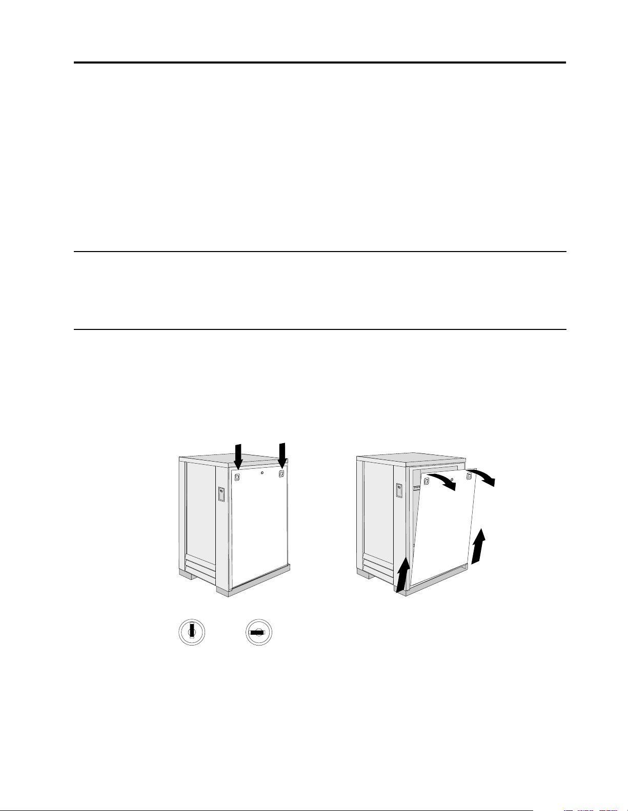
Type 9306 Model 200
Locked Unlocked
Features. . . . . . . . . . . . . . . . . . . . . . . . . . . . . . . . . . . . 21
Locations. . . . . . . . . . . . . . . . . . . . . . . . . . . . . . . . . . . 21
Side panel . . . . . . . . . . . . . . . . . . . . . . . . . . . . . . . . . . 21
Selector switch locations . . . . . . . . . . . . . . . . . . . . . 22
Power Distribution Unit. . . . . . . . . . . . . . . . . . . . . . 26
Blank bezel . . . . . . . . . . . . . . . . . . . . . . . . . . . . . . . . . 27
Fixed shelf . . . . . . . . . . . . . . . . . . . . . . . . . . . . . . . . . 27
Keyboard tray . . . . . . . . . . . . . . . . . . . . . . . . . . . . . . 28
Installing a flat panel monitor rack mount kit . . . 29
Features
The IBM NetBAY22, Type 9306, Model 200 Rack enclosure is a 22-U high (38.5-inch)
industry-standard, 19-inch rack that houses and controls multiple IBM PC
Servers/IBM Servers and related equipment.
Locations
The following sections contain information on specific equipment locations.
Note: For instructi ons on how to power-off the rack, see “Powering off the rack” on
page 3.
Side pa nel
Removing the existing flat panel monitor stand . 29
Installing the new monitor stand. . . . . . . . . . . . . . 31
Starting the system. . . . . . . . . . . . . . . . . . . . . . . . . . 35
Configuring the selector switch . . . . . . . . . . . . . . . 35
Switching among servers . . . . . . . . . . . . . . . . . . . . 36
Advanced selector switch functions . . . . . . . . . . . 37
Resetting the selector switch. . . . . . . . . . . . . . . . . . 45
Making connections under power. . . . . . . . . . . . . 46
Parts Listing (Type 9306 Model 200) . . . . . . . . . . . 47
© Copyright IBM Corp. 2001 21
Page 30
Selecto r switch locat io ns
Note: For information about the IBM NetBAY Console Switch, see “IBM NetBAY
console switch” on page 129.
e
e
r
h
T
e
e
r
h
T
M
K
o
Tw
M
e
K
e
r
h
T
M
K
o
Tw
M
K
e
n
O
M
K
t
e
s
e
R
M
K
.
x
u
A
Figure 1. Selector switch in monitor compartment
1
n
0
t
tio
e
e
r
a
h
T
rm
ortan
o
fo
p
Tw
In
M
Im
K
M
K
22 Hardware Ma intena nce Manual: IBM PC Server/Enterprise Rack s
Page 31

FRONT
0
1
Inform
ation
Im
po
rtant
M
K
Three
M
K
Two
M
K
Three
M
K
Three
M
K
Two
M
K
Three
M
K
Two
M
K
One
Aux.
Reset
REAR
Figure 2. Selector switch between side panels
Figure 3. Selector switch rear of rack with blank panel front of rack
Type 9306 Mod e l 200 23
Page 32

o
o
Selector switch cable connections
Monitor
One
KM
Keyboard
Reset
Aux.
Mouse
Tiered switch configuration
Monitor
Keyboard
Mouse
Connectors
Reset
Aux.
One
KM
System 1 to 8
Two
Two
Three
KM
Computer 3
Keyboard
Three
KM
Computer 3
Monitor
KMKM
Computer 3
Mouse
KKM
Important
Information
Power C
Connect
Power
Switch
System 1-1 to 1-8
Reset
Aux.
One
KM
Two
Three
KM
KKM
One eight-port primary selector switch can accommodate up to eight secondary
selector switches which can then support up to 64 servers.
Note:
There are two types of selector switches available:
• 4 port
• 8 port
24 Hardware Ma intena nce Manual: IBM PC Server/Enterprise Rack s
Page 33

Selector switch environment
Monitor
Console
Cable
Set
Keyboard Mouse
Selector Switch
Server 1
Server 2
Server 3
Server 4
Figure 4. Single selector switch
Monitor
Primary Selector Switch
Console
Cable
Set
Keyboard Mouse
Server 1
Server 2
Server 3
Secondary Selector Switch
Server 4
Server 5
Figure 5. Multiple selec t o r switch
Type 9306 Mod e l 200 25
Page 34

Power Distribution Unit
Note: For information and installation instructi ons for the IBM NetBAY Rack Power
Distribu tion Units, see “Net BAY Power Distribution Units” on page 141.
REAR
Figure 6. Power Distribution vertical installation
FRONT
Figure 7. Power distribution horizontal installation
26 Hardware Ma intena nce Manual: IBM PC Server/Enterprise Rack s
Page 35

Note: There are two types of Power distribution units available:
Blank bezel
• High voltage
• Low voltage
Fixed shelf
Type 9306 Mod e l 200 27
Page 36

Keyboard tray
To remove the tray from the side rails, pul l up on the left rail tab and push down on
the rig ht ra i l ta b .
28 Hardware Ma intena nce Manual: IBM PC Server/Enterprise Rack s
Page 37
Installing a flat panel monitor rack mount kit
You can store a T54 or T55 Flat Panel Monitor in a keybo ard tray with the flat panel
monitor rack mount kit . This kit r equ ires an addition al 2U of space abo ve an inst alled
keyboard tray in your rack cab inet. See the docu me ntation that comes with the flat
panel monitor rack mount kit for detailed installation instructions. Use the following
general procedure to install a flat panel monitor in your rack cabinet:
Rear screws
Flat panel monitor
Mounting studs
Bumpers
Keyboard tray
Figure 8. Installing a flat panel monitor rack mount kit
1. Ensure that a keyboard tray is properly installed in your rack cabinet (see
“Keyboard tray” on page 28) with at least 2U of clearance above the keyboar d
tray.
2. Install the flat panel monitor base on the flat panel monitor. See the
documentation that comes with you r flat panel monitor r a ck mount kit for
detailed installat io n instruct ions .
3. Install the mounting studs and bu mp e rs on the keyboard tray.
4. Attach the monitor base to the inside of the keyboard tray using the screws that
come with the rack mount kit.
5. Fold the monitor all the way down against the bumpers; then, slide the keyboard
tray into the rack cabinet to ensure that there is proper clearance.
6. See the documentation that comes with your flat panel monitor for information
on how to connect power and how to connect the monitor to a server or console
switch.
Removing the existing flat panel monitor stand
Use the following steps to remove the existing flat panel monitor stand from your
monitor:
Type 9306 Mod e l 200 29
Page 38

1. Unplug the flat panel monitor and disconnect the power cord from the flat panel
monitor power supply.
2. Carefully use a flat-blade screwdriver to pry the bottom of the cable cover
and remove it. Save the cable cover for later reinstallation.
Figure 9. Removing the cable cover, hinge cover, and stand cover
3. Squeeze the sides of the hinge cover
Note: Even though this hinge cover is not used wi th the Flat Panel Monitor Rack
Mount Kit, do not discard it. Store it with the other monit or stand parts
you remove for possible future use.
4. Gently push the stand cover
the stand.
5. Disconnect the si gnal cable and power cor d from the flat panel monit or. Carefully
remove and save the plastic cable clamp to free the power cord.
Note: The plastic cable clamp is reusable and is needed to secure the power cord
after installing the Flat Panel Monito r Rack Moun t Kit on the flat panel
monitor.
c3d
c2d
and remove it.
and slide it backwards until it is completely off
c1d
up
Figure 10. Removing the plastic cable clamp
6. Lay the monitor facedown on a cushioned surface and remove the six screws that
secure the hinges to the flat panel monitor.
30 Hardware Ma intena nce Manual: IBM PC Server/Enterprise Rack s
Page 39

Figure 11. Removing the existing monitor stand from the monitor
7. Lift off the hinge and monitor stand assembly. Store this assembly in a safe place
for possible future use.
Installing the new monitor stand
Refer to “Removing the existing flat panel monitor stand” on page 29 for instructions
on how to remove the existing stand from the flat panel monitor. Before installing the
new stand, install the keyboard tray in the rack according to the instructions that
come with th e rack or the keyboa rd tray option.
Note: The Flat Panel Monitor Rack Mount Kit and keyboard tray require 3U of rack
mounting space. If the keyboard tray does not have at least 2U of clearance
above it, relocate the keyboard tray within the rack.
Use the following steps to install the Flat Panel Monitor Rack Mount Kit:
1. Remove the cable cover
screws (two per hinge) that secure the hinges
c1d
from the new monitor stand; then, remove the four
c2d
to the stand.
Figure 12. Removing the hinges from the new monitor stand
2. Install the hinges on the flat panel monitor, using the six screws that you removed
from the old monitor stand.
Type 9306 Mod e l 200 31
Page 40

Figure 13. Installing the hinges on the flat panel monitor
Note: Be sure to slide eac h hinge into place on the back of the monitor and align
the holes in the hinges with holes on the monitor.
3. Lower the flat panel monitor onto the new monitor stand, making sure that you
align the holes in the stand with holes in the hinges; then, secure the flat panel
monitor to the monitor stand with the four screws that you removed earlier.
Figure 14. Installing the monitor on the new monitor stand
You have now finished attaching the flat panel monitor to its stand. The rest of
the installation process involves prepar ing the keyboard tray for storage and
rou tin g cable s.
Notes:
a. You must r e move any keyboar d or mouse that i s already in the keyboard tray
before continuing.
b. You will not be able to store a mouse in the keyboard tray after installing the
Flat Panel Monitor Rack Mount Kit.
c. You can only store a space-saver keyboard in the keyboard tray.
4. Install the mounting studs
mounting hardware package.
c2d
and bumpers c3d that come in the monitor
32 Hardware Ma intena nce Manual: IBM PC Server/Enterprise Rack s
Page 41

Figure 15. Installing the flat panel monitor in the keyboard tray
Note: Clean the installation area on the keyboard tray with a suitable cleaning
agent, such as alcohol, before installing the rubber bumpers on the front of
the keyboar d tray.
5. Open the flat pan el monito r
the stand with the mounting s tu ds
c1d
to its full upright position and align the grooves in
c2d
in the keyboard tray. When the monitor
stand is sitting inside the keyboard tray, slide it towards the back until it stops.
Note: Install or remove the flat panel monitor only when the display is in its
upright position.
6. Secure th e monitor stand in the back of the keyboard tray with the two provided
screws
c4d
.
7. Place the flat panel monitor power supply, which came with your flat panel
monitor, inside the monitor stand. If necessary, insert the power supply spacer
c3d
behind the power supply and over the cable to keep the power supply in
place.
Type 9306 Mod e l 200 33
Page 42

Figure 16. Storing the power supply and routing cables
8. Connect the power supply to the monitor and route the cable under the tab near
the top of the monitor stand
clamp you removed from the original stan d and coil excess cabl e in side the
monitor stand.
9. Connect the mon itor signal cab le to the monitor and route it under the tab in the
bottom of the m onitor sta n d
provided.
10. Replace the monitor stand cover
c1d
; then, secure the power cable with the cable
c2d
and ou t th e ba ck of the stand th rou gh the hol e
c1d
.
Figure 17. Installing the cable cover, hinge cover, and stand cover
11. Snap the new hinge cover
Note: Be sure to use the new hinge cover that comes with the Flat Panel Monitor
Rack Mount Kit because it has deeper grooves to accommodate the new
hinge assembly.
New hinge cover Ol d hinge cover
12. Snap the cable cover
13. Fold the flat panel monitor do wn until it rests o n the rubber bumpers; then, gently
push back and remove the small cable exit cover
c2d
into place over the hinge assembly.
c3d
into place on the back of the flat panel monitor .
c1d
on the monitor stand.
34 Hardware Ma intena nce Manual: IBM PC Server/Enterprise Rack s
Page 43

Figure 18. Routing the keyboard cable
14. Route the space-saver keyboard cabl e thro ugh the hole in t he front o f the base an d
out the opening in the back where you removed the small cover; then, place the
keyboard (with its adjustable feet fully down) inside the keyboard tray .
Note: You must open the flat panel monitor to its full upright position so that
you can install the keyboard and route its cable.
15. Fold the flat panel monitor down again until it rest s on the rubber bumpers; then,
reinstall the small cable exit cover
16. Slide the keyboard tray i nto the rack; t hen, neat ly route and secure all cables in the
rack using the provided cable straps.
You can now connect the power cord to the flat panel monitor and connect the
display to a server.
Starting the system
Start the system by:
1. Power-on the selector switch(s).
2. Power-on the monitor.
3. Power-on the servers.
Note: The selector switch must be powered on first, then the servers. This is to
assure that the device drivers for the servers send device settings to the
selector switch.
c1d
.
When the selector switch is powered on, it:
• Identifies the mouse and keyboard and puts them into default status.
• Switches to port 1 by default, and displays the number '1' in the status flag field
on the monitor.
Configuring the selector switch
Note: For information about the IBM NetBAY Console Switch, see “IBM NetBAY
console switch” on page 129.
Note: Some selector switch units have dif f e rent funct ions and displays. Refer to the
Apex PC Sol utions® Outlook™ Concentrator User Guide. This guide is
shipped with the Selector Switch Unit.
No configuration is necessary for norma l swit ch operati on.
Type 9306 Mod e l 200 35
Page 44

Switch configuration can be performed to:
• Assign unique names to servers.
• Display servers by their assi gned port names and port numbers.
Switching among servers
To switch among servers:
• Press the Print Screen key.
• Type the port number of the server to be switched.
• Press Ente r.
Note: One depression of the Print Screen key starts the switching process. To
print a screen, depress the Print Screen key twice.
Port Name
Port Name
Port Name
Port Name
Port Name
Port Name
Port Name
Port Name
Port Name
Port Name
Port Name
Port Name
Port Name
Port Name
Port Name
Port Name
Port Name
Port Name
Port Name
Port Name
Port Name
Port Name
Port Name
Port Name
Port Name
Port Name
Port Name
Port Name
Port Name
Port Name
1 Magic +
1 Magic +
1 Magic +
1 Magic +
1 Magic +
1 Magic +
1 Magic +
1 Magic +
1 Magic +
1 Magic +
1 Magic +
1 Magic +
1 Magic +
1 Magic +
1 Magic +
1 Magic +
1 Magic +
1 Magic +
1 Magic +
1 Magic +
1 Magic +
1 Magic +
1 Magic +
1 Magic +
1 Magic +
1 Magic +
1 Magic +
1 Magic +
1 Magic +
1 Magic +
2 CentralOfc +
2 CentralOfc +
2 CentralOfc +
2 CentralOfc +
2 CentralOfc +
2 CentralOfc +
2 CentralOfc +
2 CentralOfc +
2 CentralOfc +
2 CentralOfc +
2 CentralOfc +
2 CentralOfc +
2 CentralOfc +
2 CentralOfc +
2 CentralOfc +
2 CentralOfc +
2 CentralOfc +
2 CentralOfc +
2 CentralOfc +
2 CentralOfc +
2 CentralOfc +
2 CentralOfc +
2 CentralOfc +
2 CentralOfc +
2 CentralOfc +
2 CentralOfc +
2 CentralOfc +
2 CentralOfc +
2 CentralOfc +
2 CentralOfc +
3 Sales-C +
3 Sales-C +
3 Sales-C +
3 Sales-C +
3 Sales-C +
3 Sales-C +
3 Sales-C +
3 Sales-C +
3 Sales-C +
3 Sales-C +
3 Sales-C +
3 Sales-C +
3 Sales-C +
3 Sales-C +
3 Sales-C +
3 Sales-C +
3 Sales-C +
3 Sales-C +
3 Sales-C +
3 Sales-C +
3 Sales-C +
3 Sales-C +
3 Sales-C +
3 Sales-C +
3 Sales-C +
3 Sales-C +
3 Sales-C +
3 Sales-C +
3 Sales-C +
3 Sales-C +
4 Sales-B
4 Sales-B
4 Sales-B
4 Sales-B
4 Sales-B
4 Sales-B
4 Sales-B
4 Sales-B
4 Sales-B
4 Sales-B
4 Sales-B
4 Sales-B
4 Sales-B
4 Sales-B
4 Sales-B
4 Sales-B
4 Sales-B
4 Sales-B
4 Sales-B
4 Sales-B
4 Sales-B
4 Sales-B
4 Sales-B
4 Sales-B
4 Sales-B
4 Sales-B
4 Sales-B
4 Sales-B
4 Sales-B
4 Sales-B
5 Sales-A +
5 Sales-A +
5 Sales-A +
5 Sales-A +
5 Sales-A +
5 Sales-A +
5 Sales-A +
5 Sales-A +
5 Sales-A +
5 Sales-A +
5 Sales-A +
5 Sales-A +
5 Sales-A +
5 Sales-A +
5 Sales-A +
5 Sales-A +
5 Sales-A +
5 Sales-A +
5 Sales-A +
5 Sales-A +
5 Sales-A +
5 Sales-A +
5 Sales-A +
5 Sales-A +
5 Sales-A +
5 Sales-A +
5 Sales-A +
5 Sales-A +
5 Sales-A +
5 Sales-A +
6 Downtown
6 Downtown
6 Downtown
6 Downtown
6 Downtown
6 Downtown
6 Downtown
6 Downtown
6 Downtown
6 Downtown
6 Downtown
6 Downtown
6 Downtown
6 Downtown
6 Downtown
6 Downtown
6 Downtown
6 Downtown
6 Downtown
6 Downtown
6 Downtown
6 Downtown
6 Downtown
6 Downtown
6 Downtown
6 Downtown
6 Downtown
6 Downtown
6 Downtown
6 Downtown
7 Foreign +
7 Foreign +
7 Foreign +
7 Foreign +
7 Foreign +
7 Foreign +
7 Foreign +
7 Foreign +
7 Foreign +
7 Foreign +
7 Foreign +
7 Foreign +
7 Foreign +
7 Foreign +
7 Foreign +
7 Foreign +
7 Foreign +
7 Foreign +
7 Foreign +
7 Foreign +
7 Foreign +
7 Foreign +
7 Foreign +
7 Foreign +
7 Foreign +
7 Foreign +
7 Foreign +
7 Foreign +
7 Foreign +
7 Foreign +
8
8
8
8
8
8
8
8
8
8
8
8
8
8
8
8
8
8
8
8
8
8
8
8
8
8
8
8
8
8
F1 Help F2 Advanced
F1 Help F2 Advanced
F1 Help F2 Advanced
F1 Help F2 Advanced
F1 Help F2 Advanced
F1 Help F2 Advanced
F1 Help F2 Advanced
F1 Help F2 Advanced
F1 Help F2 Advanced
F1 Help F2 Advanced
F1 Help F2 Advanced
F1 Help F2 Advanced
F1 Help F2 Advanced
F1 Help F2 Advanced
F1 Help F2 Advanced
F1 Help F2 Advanced
F1 Help F2 Advanced
F1 Help F2 Advanced
F1 Help F2 Advanced
F1 Help F2 Advanced
F1 Help F2 Advanced
F1 Help F2 Advanced
F1 Help F2 Advanced
F1 Help F2 Advanced
F1 Help F2 Advanced
F1 Help F2 Advanced
F1 Help F2 Advanced
F1 Help F2 Advanced
F1 Help F2 Advanced
F1 Help F2 Advanced
36 Hardware Ma intena nce Manual: IBM PC Server/Enterprise Rack s
Page 45

Port Name
Port Name
Port Name
Port Name
Port Name
Port Name
Port Name
Port Name
Port Name
Port Name
Port Name
Port Name
Port Name
Port Name
Port Name
Port Name
Port Name
Port Name
Port Name
Port Name
Port Name
Port Name
Port Name
Port Name
Port Name
Port Name
Port Name
Port Name
Port Name
Port Name
CentralOfc 2 +
CentralOfc 2 +
CentralOfc 2 +
CentralOfc 2 +
CentralOfc 2 +
CentralOfc 2 +
CentralOfc 2 +
CentralOfc 2 +
CentralOfc 2 +
CentralOfc 2 +
CentralOfc 2 +
CentralOfc 2 +
CentralOfc 2 +
CentralOfc 2 +
CentralOfc 2 +
CentralOfc 2 +
CentralOfc 2 +
CentralOfc 2 +
CentralOfc 2 +
CentralOfc 2 +
CentralOfc 2 +
CentralOfc 2 +
CentralOfc 2 +
CentralOfc 2 +
CentralOfc 2 +
CentralOfc 2 +
CentralOfc 2 +
CentralOfc 2 +
CentralOfc 2 +
CentralOfc 2 +
Downtown 6
Downtown 6
Downtown 6
Downtown 6
Downtown 6
Downtown 6
Downtown 6
Downtown 6
Downtown 6
Downtown 6
Downtown 6
Downtown 6
Downtown 6
Downtown 6
Downtown 6
Downtown 6
Downtown 6
Downtown 6
Downtown 6
Downtown 6
Downtown 6
Downtown 6
Downtown 6
Downtown 6
Downtown 6
Downtown 6
Downtown 6
Downtown 6
Downtown 6
Downtown 6
Foreign 7 +
Foreign 7 +
Foreign 7 +
Foreign 7 +
Foreign 7 +
Foreign 7 +
Foreign 7 +
Foreign 7 +
Foreign 7 +
Foreign 7 +
Foreign 7 +
Foreign 7 +
Foreign 7 +
Foreign 7 +
Foreign 7 +
Foreign 7 +
Foreign 7 +
Foreign 7 +
Foreign 7 +
Foreign 7 +
Foreign 7 +
Foreign 7 +
Foreign 7 +
Foreign 7 +
Foreign 7 +
Foreign 7 +
Foreign 7 +
Foreign 7 +
Foreign 7 +
Foreign 7 +
Magic 1 +
Magic 1 +
Magic 1 +
Magic 1 +
Magic 1 +
Magic 1 +
Magic 1 +
Magic 1 +
Magic 1 +
Magic 1 +
Magic 1 +
Magic 1 +
Magic 1 +
Magic 1 +
Magic 1 +
Magic 1 +
Magic 1 +
Magic 1 +
Magic 1 +
Magic 1 +
Magic 1 +
Magic 1 +
Magic 1 +
Magic 1 +
Magic 1 +
Magic 1 +
Magic 1 +
Magic 1 +
Magic 1 +
Magic 1 +
Sales-A 5 +
Sales-A 5 +
Sales-A 5 +
Sales-A 5 +
Sales-A 5 +
Sales-A 5 +
Sales-A 5 +
Sales-A 5 +
Sales-A 5 +
Sales-A 5 +
Sales-A 5 +
Sales-A 5 +
Sales-A 5 +
Sales-A 5 +
Sales-A 5 +
Sales-A 5 +
Sales-A 5 +
Sales-A 5 +
Sales-A 5 +
Sales-A 5 +
Sales-A 5 +
Sales-A 5 +
Sales-A 5 +
Sales-A 5 +
Sales-A 5 +
Sales-A 5 +
Sales-A 5 +
Sales-A 5 +
Sales-A 5 +
Sales-A 5 +
Sales-B 4
Sales-B 4
Sales-B 4
Sales-B 4
Sales-B 4
Sales-B 4
Sales-B 4
Sales-B 4
Sales-B 4
Sales-B 4
Sales-B 4
Sales-B 4
Sales-B 4
Sales-B 4
Sales-B 4
Sales-B 4
Sales-B 4
Sales-B 4
Sales-B 4
Sales-B 4
Sales-B 4
Sales-B 4
Sales-B 4
Sales-B 4
Sales-B 4
Sales-B 4
Sales-B 4
Sales-B 4
Sales-B 4
Sales-B 4
Sales-C 3 +
Sales-C 3 +
Sales-C 3 +
Sales-C 3 +
Sales-C 3 +
Sales-C 3 +
Sales-C 3 +
Sales-C 3 +
Sales-C 3 +
Sales-C 3 +
Sales-C 3 +
Sales-C 3 +
Sales-C 3 +
Sales-C 3 +
Sales-C 3 +
Sales-C 3 +
Sales-C 3 +
Sales-C 3 +
Sales-C 3 +
Sales-C 3 +
Sales-C 3 +
Sales-C 3 +
Sales-C 3 +
Sales-C 3 +
Sales-C 3 +
Sales-C 3 +
Sales-C 3 +
Sales-C 3 +
Sales-C 3 +
Sales-C 3 +
8
8
8
8
8
8
8
8
8
8
8
8
8
8
8
8
8
8
8
8
8
8
8
8
8
8
8
8
8
8
F1 Help F2 Advanced
F1 Help F2 Advanced
F1 Help F2 Advanced
F1 Help F2 Advanced
F1 Help F2 Advanced
F1 Help F2 Advanced
F1 Help F2 Advanced
F1 Help F2 Advanced
F1 Help F2 Advanced
F1 Help F2 Advanced
F1 Help F2 Advanced
F1 Help F2 Advanced
F1 Help F2 Advanced
F1 Help F2 Advanced
F1 Help F2 Advanced
F1 Help F2 Advanced
F1 Help F2 Advanced
F1 Help F2 Advanced
F1 Help F2 Advanced
F1 Help F2 Advanced
F1 Help F2 Advanced
F1 Help F2 Advanced
F1 Help F2 Advanced
F1 Help F2 Advanced
F1 Help F2 Advanced
F1 Help F2 Advanced
F1 Help F2 Advanced
F1 Help F2 Advanced
F1 Help F2 Advanced
F1 Help F2 Advanced
• Using the Up Arrow (h and Down Arrow (d), select the server you want to
switch to, or press the numeric key that corresponds to the server’s port number
and then press Enter.
The symbol s after the Port or Name columns on the menu show the status of the port
as follows:
Type of Symbol Symbol Meaning
Plus + Server connected and running
Asterisk * Secondary selector switch connected and running
Advanced selector switch functions
System configuration is performed through the keyboard and menus to include these
Advanced selector switch functions:
• Scanning the servers
• Displaying server BIOS versions and settings
• Saving the Hardware Configuration
• Resetting the mouse and keyboard
• Setting a scan pattern
• Assigning unique names to the servers
• Listing servers by name or port number (Changing Menu Attributes)
• Changing the posit ion and col or of the operation menus and windows (Cha nging
Flag Attributes)
• Assigning a specific monitor type to a certain port (server)
Type 9306 Mod e l 200 37
Page 46

Scanning the servers
To place the selector switch in scan mode:
• Press the Print Screen key
• Press the F2 key to display the Advanced Menu screen.
• Using the Up Arrow (
Scan and press Enter. The selector switch enters the scan mode and the display
returns to the status flag. To cancel the operation, press Esc any time before you
press Enter.
• To cancel the scan mode, press any key or move the mouse. The scan stops at the
currently connected server.
h
) and Down Arrow (d) keys, move the highlighting to
Displaying version information and device settings
The select or switch BIOS version numbe r along with keyboard and mouse
information can be displayed for the currently selected server.
• Press the Print Screen key.
• Press the F2 key to display the Advanced Menu screen.
• Using the Up Arrow (
Version and press Enter.
h
) and Down Arrow (d) keys, move the highlighting to
Version
Version
Version
Version
Version
Version
Version
Version
Version
Version
Version
Version
Version
Version
Version
Version
Version
Version
Version
Version
Version
Version
Version
Version
Version
Version
Version
Version
Version
Version
BIOS X.XX
BIOS X.XX
BIOS X.XX
BIOS X.XX
BIOS X.XX
BIOS X.XX
BIOS X.XX
BIOS X.XX
BIOS X.XX
BIOS X.XX
BIOS X.XX
BIOS X.XX
BIOS X.XX
BIOS X.XX
BIOS X.XX
BIOS X.XX
BIOS X.XX
BIOS X.XX
BIOS X.XX
BIOS X.XX
BIOS X.XX
BIOS X.XX
BIOS X.XX
BIOS X.XX
BIOS X.XX
BIOS X.XX
BIOS X.XX
BIOS X.XX
BIOS X.XX
BIOS X.XX
Hardware X X
Hardware X X
Hardware X X
Hardware X X
Hardware X X
Hardware X X
Hardware X X
Hardware X X
Hardware X X
Hardware X X
Hardware X X
Hardware X X
Hardware X X
Hardware X X
Hardware X X
Hardware X X
Hardware X X
Hardware X X
Hardware X X
Hardware X X
Hardware X X
Hardware X X
Hardware X X
Hardware X X
Hardware X X
Hardware X X
Hardware X X
Hardware X X
Hardware X X
Hardware X X
Port 1 Magic 1
Port 1 Magic 1
Port 1 Magic 1
Port 1 Magic 1
Port 1 Magic 1
Port 1 Magic 1
Port 1 Magic 1
Port 1 Magic 1
Port 1 Magic 1
Port 1 Magic 1
Port 1 Magic 1
Port 1 Magic 1
Port 1 Magic 1
Port 1 Magic 1
Port 1 Magic 1
Port 1 Magic 1
Port 1 Magic 1
Port 1 Magic 1
Port 1 Magic 1
Port 1 Magic 1
Port 1 Magic 1
Port 1 Magic 1
Port 1 Magic 1
Port 1 Magic 1
Port 1 Magic 1
Port 1 Magic 1
Port 1 Magic 1
Port 1 Magic 1
Port 1 Magic 1
Port 1 Magic 1
Keyboard Mouse
Keyboard Mouse
Keyboard Mouse
Keyboard Mouse
Keyboard Mouse
Keyboard Mouse
Keyboard Mouse
Keyboard Mouse
Keyboard Mouse
Keyboard Mouse
Keyboard Mouse
Keyboard Mouse
Keyboard Mouse
Keyboard Mouse
Keyboard Mouse
Keyboard Mouse
Keyboard Mouse
Keyboard Mouse
Keyboard Mouse
Keyboard Mouse
Keyboard Mouse
Keyboard Mouse
Keyboard Mouse
Keyboard Mouse
Keyboard Mouse
Keyboard Mouse
Keyboard Mouse
Keyboard Mouse
Keyboard Mouse
Keyboard Mouse
Enabled Enabled
Enabled Enabled
Enabled Enabled
Enabled Enabled
Enabled Enabled
Enabled Enabled
Enabled Enabled
Enabled Enabled
Enabled Enabled
Enabled Enabled
Enabled Enabled
Enabled Enabled
Enabled Enabled
Enabled Enabled
Enabled Enabled
Enabled Enabled
Enabled Enabled
Enabled Enabled
Enabled Enabled
Enabled Enabled
Enabled Enabled
Enabled Enabled
Enabled Enabled
Enabled Enabled
Enabled Enabled
Enabled Enabled
Enabled Enabled
Enabled Enabled
Enabled Enabled
Enabled Enabled
Rate 2C Rate 100
Rate 2C Rate 100
Rate 2C Rate 100
Rate 2C Rate 100
Rate 2C Rate 100
Rate 2C Rate 100
Rate 2C Rate 100
Rate 2C Rate 100
Rate 2C Rate 100
Rate 2C Rate 100
Rate 2C Rate 100
Rate 2C Rate 100
Rate 2C Rate 100
Rate 2C Rate 100
Rate 2C Rate 100
Rate 2C Rate 100
Rate 2C Rate 100
Rate 2C Rate 100
Rate 2C Rate 100
Rate 2C Rate 100
Rate 2C Rate 100
Rate 2C Rate 100
Rate 2C Rate 100
Rate 2C Rate 100
Rate 2C Rate 100
Rate 2C Rate 100
Rate 2C Rate 100
Rate 2C Rate 100
Rate 2C Rate 100
Rate 2C Rate 100
LEDs 2 Res 2
LEDs 2 Res 2
LEDs 2 Res 2
LEDs 2 Res 2
LEDs 2 Res 2
LEDs 2 Res 2
LEDs 2 Res 2
LEDs 2 Res 2
LEDs 2 Res 2
LEDs 2 Res 2
LEDs 2 Res 2
LEDs 2 Res 2
LEDs 2 Res 2
LEDs 2 Res 2
LEDs 2 Res 2
LEDs 2 Res 2
LEDs 2 Res 2
LEDs 2 Res 2
LEDs 2 Res 2
LEDs 2 Res 2
LEDs 2 Res 2
LEDs 2 Res 2
LEDs 2 Res 2
LEDs 2 Res 2
LEDs 2 Res 2
LEDs 2 Res 2
LEDs 2 Res 2
LEDs 2 Res 2
LEDs 2 Res 2
LEDs 2 Res 2
Mode 2
Mode 2
Mode 2
Mode 2
Mode 2
Mode 2
Mode 2
Mode 2
Mode 2
Mode 2
Mode 2
Mode 2
Mode 2
Mode 2
Mode 2
Mode 2
Mode 2
Mode 2
Mode 2
Mode 2
Mode 2
Mode 2
Mode 2
Mode 2
Mode 2
Mode 2
Mode 2
Mode 2
Mode 2
Mode 2
Type 101 Type Gen
Type 101 Type Gen
Type 101 Type Gen
Type 101 Type Gen
Type 101 Type Gen
Type 101 Type Gen
Type 101 Type Gen
Type 101 Type Gen
Type 101 Type Gen
Type 101 Type Gen
Type 101 Type Gen
Type 101 Type Gen
Type 101 Type Gen
Type 101 Type Gen
Type 101 Type Gen
Type 101 Type Gen
Type 101 Type Gen
Type 101 Type Gen
Type 101 Type Gen
Type 101 Type Gen
Type 101 Type Gen
Type 101 Type Gen
Type 101 Type Gen
Type 101 Type Gen
Type 101 Type Gen
Type 101 Type Gen
Type 101 Type Gen
Type 101 Type Gen
Type 101 Type Gen
Type 101 Type Gen
• Keyboard information includes:
— Enabled or disabled
— Typematic rate
— LED settings
— Port mode
— Keyboard type.
• Mouse information includes:
38 Hardware Ma intena nce Manual: IBM PC Server/Enterprise Rack s
Page 47

— Enabled or disabled
— Sample rate
— Resolution
— Mouse type
• Press Esc to remove the Version menu.
Saving Hardware Configuration
Whenever servers are added to or r emoved fro m the configurat ion, or whenever there
is a change in the mouse or monitor, save the hardware configuration setting by:
1. Press the Print Screen key.
2. Press the F2 key to display the Advanced Menu screen.
3. Using the Up Arrow (
Snapshot and press the Enter key. The hardware settings are saved to memory.
Important: If the settings are not saved and the selector switch power is lost, it might
be necessary to restart each server in the configuration to reestablish
keyboard and mouse communications.
h
) and Down Arrow (d) keys, move the highlighting to
Resetting the mouse and keyboard
Resetting the mouse and keyboard restores the default setting for the selected server.
• Press the Print Screen key.
• Press the F2 key to display the Advanced Menu screen.
• Using the Up Arrow (
Reset and press the Enter key. The mouse and keyboard are now reset.
h
) and Down Arrow (d) keys, move the highlighting to
Setting a scan pattern
The selector switch has a standard scan routine for sequentially connecting each
server to the monitor, keyboard, and mouse. The scan routine can be configured to
scan all or any of the servers in a particular pattern. To create a scan pattern, do the
following.
1. Press the Print Screen key.
2. Press the F2 key to display the Advanced Menu screen. Press the Right Arrow
(
g
) key to move the highlight to the Setup Menu .
3. Using the Up Arrow (
Scan and press the Enter key. The Scan Pattern Setup menu appears with the first
port position or server name highlighted. The following example screen displays
when the port order mode is selected.
h
) and Down Arrow (d) keys, move the highlighting to
Type 9306 Mod e l 200 39
Page 48

Scan Pattern Setup
Scan Pattern Setup
Scan Pattern Setup
Scan Pattern Setup
Scan Pattern Setup
Scan Pattern Setup
Scan Pattern Setup
Scan Pattern Setup
Scan Pattern Setup
Scan Pattern Setup
Scan Pattern Setup
Scan Pattern Setup
Scan Pattern Setup
Scan Pattern Setup
Scan Pattern Setup
Scan Pattern Setup
Scan Pattern Setup
Scan Pattern Setup
Scan Pattern Setup
Scan Pattern Setup
Scan Pattern Setup
Scan Pattern Setup
Scan Pattern Setup
Scan Pattern Setup
Scan Pattern Setup
Scan Pattern Setup
Scan Pattern Setup
Scan Pattern Setup
Scan Pattern Setup
Scan Pattern Setup
Port/Sec Name
Port/Sec Name
Port/Sec Name
Port/Sec Name
Port/Sec Name
Port/Sec Name
Port/Sec Name
Port/Sec Name
Port/Sec Name
Port/Sec Name
Port/Sec Name
Port/Sec Name
Port/Sec Name
Port/Sec Name
Port/Sec Name
Port/Sec Name
Port/Sec Name
Port/Sec Name
Port/Sec Name
Port/Sec Name
Port/Sec Name
Port/Sec Name
Port/Sec Name
Port/Sec Name
Port/Sec Name
Port/Sec Name
Port/Sec Name
Port/Sec Name
Port/Sec Name
Port/Sec Name
6/20 Downtown
6/20 Downtown
6/20 Downtown
6/20 Downtown
6/20 Downtown
6/20 Downtown
6/20 Downtown
6/20 Downtown
6/20 Downtown
6/20 Downtown
6/20 Downtown
6/20 Downtown
6/20 Downtown
6/20 Downtown
6/20 Downtown
6/20 Downtown
6/20 Downtown
6/20 Downtown
6/20 Downtown
6/20 Downtown
6/20 Downtown
6/20 Downtown
6/20 Downtown
6/20 Downtown
6/20 Downtown
6/20 Downtown
6/20 Downtown
6/20 Downtown
6/20 Downtown
6/20 Downtown
5/20 Sales-A
5/20 Sales-A
5/20 Sales-A
5/20 Sales-A
5/20 Sales-A
5/20 Sales-A
5/20 Sales-A
5/20 Sales-A
5/20 Sales-A
5/20 Sales-A
5/20 Sales-A
5/20 Sales-A
5/20 Sales-A
5/20 Sales-A
5/20 Sales-A
5/20 Sales-A
5/20 Sales-A
5/20 Sales-A
5/20 Sales-A
5/20 Sales-A
5/20 Sales-A
5/20 Sales-A
5/20 Sales-A
5/20 Sales-A
5/20 Sales-A
5/20 Sales-A
5/20 Sales-A
5/20 Sales-A
5/20 Sales-A
5/20 Sales-A
4/10 Sales-B
4/10 Sales-B
4/10 Sales-B
4/10 Sales-B
4/10 Sales-B
4/10 Sales-B
4/10 Sales-B
4/10 Sales-B
4/10 Sales-B
4/10 Sales-B
4/10 Sales-B
4/10 Sales-B
4/10 Sales-B
4/10 Sales-B
4/10 Sales-B
4/10 Sales-B
4/10 Sales-B
4/10 Sales-B
4/10 Sales-B
4/10 Sales-B
4/10 Sales-B
4/10 Sales-B
4/10 Sales-B
4/10 Sales-B
4/10 Sales-B
4/10 Sales-B
4/10 Sales-B
4/10 Sales-B
4/10 Sales-B
4/10 Sales-B
1/10 Match
1/10 Match
1/10 Match
1/10 Match
1/10 Match
1/10 Match
1/10 Match
1/10 Match
1/10 Match
1/10 Match
1/10 Match
1/10 Match
1/10 Match
1/10 Match
1/10 Match
1/10 Match
1/10 Match
1/10 Match
1/10 Match
1/10 Match
1/10 Match
1/10 Match
1/10 Match
1/10 Match
1/10 Match
1/10 Match
1/10 Match
1/10 Match
1/10 Match
1/10 Match
F2 for defaults
F2 for defaults
F2 for defaults
F2 for defaults
F2 for defaults
F2 for defaults
F2 for defaults
F2 for defaults
F2 for defaults
F2 for defaults
F2 for defaults
F2 for defaults
F2 for defaults
F2 for defaults
F2 for defaults
F2 for defaults
F2 for defaults
F2 for defaults
F2 for defaults
F2 for defaults
F2 for defaults
F2 for defaults
F2 for defaults
F2 for defaults
F2 for defaults
F2 for defaults
F2 for defaults
F2 for defaults
F2 for defaults
F2 for defaults
If Name order was selected, the Port and Name columns will be reversed.
4. Using the keyboard keys, select the port number of the first server to be included
in the scan. Note that the server name, if any is assigned, appears in the far right
column on th e menu.
5. Press the Tab key or Right Arrow (
column. Then, use the keyboard keys to enter a time value, in seconds, for the
length of time you want this server to be connected to the monitor and keyboard,
before switching to the next server in the scan.
6. Press the Down Arrow (
Port column and repeat step 5. To delete unwanted ports from the scan list in the
Scan Pattern Setup window, place the highlighting on the top-most port to be
removed and press the Delete key (not the Del key on the numeric keypad).
7. When you have finished setting the scan pattern, press the Enter key. Press Esc at
any time before pressing Enter to retain the previous scan pattern.
Note: Pressing the F2 key will return all Port and Sec values to the factory
defaults.
8. To exit, press Esc.
d
) key to move the highlighting to the next port in the
g
) key to move the highlighting to the Sec
Assigning Unique Names to Servers
Unique na mes ca n be given to s erver s and s econdary se lect or swi tche s. To assign
names:
1. Press the Print Screen key
2. Press the F2 key to display the Advanced Menu screen.
Press the Right Arrow (
3. Using the Up Arrow (
Names and press the Enter key. The Port Naming menu appears, as shown
below.
40 Hardware Ma intena nce Manual: IBM PC Server/Enterprise Rack s
g
) key to move th e highlight to the Setup Menu.
h
) and Down Arrow (d) keys, move the highlighting to
Page 49

Port Naming
Port Naming
Port Naming
Port Naming
Port Naming
Port Naming
Port Naming
Port Naming
Port Naming
Port Naming
Port Naming
Port Naming
Port Naming
Port Naming
Port Naming
Port Naming
Port Naming
Port Naming
Port Naming
Port Naming
Port Naming
Port Naming
Port Naming
Port Naming
Port Naming
Port Naming
Port Naming
Port Naming
Port Naming
Port Naming
Port Name
Port Name
Port Name
Port Name
Port Name
Port Name
Port Name
Port Name
Port Name
Port Name
Port Name
Port Name
Port Name
Port Name
Port Name
Port Name
Port Name
Port Name
Port Name
Port Name
Port Name
Port Name
Port Name
Port Name
Port Name
Port Name
Port Name
Port Name
Port Name
Port Name
1 MAGIC
1 MAGIC
1 MAGIC
1 MAGIC
1 MAGIC
1 MAGIC
1 MAGIC
1 MAGIC
1 MAGIC
1 MAGIC
1 MAGIC
1 MAGIC
1 MAGIC
1 MAGIC
1 MAGIC
1 MAGIC
1 MAGIC
1 MAGIC
1 MAGIC
1 MAGIC
1 MAGIC
1 MAGIC
1 MAGIC
1 MAGIC
1 MAGIC
1 MAGIC
1 MAGIC
1 MAGIC
1 MAGIC
1 MAGIC
2 CENTRALOFC
2 CENTRALOFC
2 CENTRALOFC
2 CENTRALOFC
2 CENTRALOFC
2 CENTRALOFC
2 CENTRALOFC
2 CENTRALOFC
2 CENTRALOFC
2 CENTRALOFC
2 CENTRALOFC
2 CENTRALOFC
2 CENTRALOFC
2 CENTRALOFC
2 CENTRALOFC
2 CENTRALOFC
2 CENTRALOFC
2 CENTRALOFC
2 CENTRALOFC
2 CENTRALOFC
2 CENTRALOFC
2 CENTRALOFC
2 CENTRALOFC
2 CENTRALOFC
2 CENTRALOFC
2 CENTRALOFC
2 CENTRALOFC
2 CENTRALOFC
2 CENTRALOFC
2 CENTRALOFC
3 SALES-C
3 SALES-C
3 SALES-C
3 SALES-C
3 SALES-C
3 SALES-C
3 SALES-C
3 SALES-C
3 SALES-C
3 SALES-C
3 SALES-C
3 SALES-C
3 SALES-C
3 SALES-C
3 SALES-C
3 SALES-C
3 SALES-C
3 SALES-C
3 SALES-C
3 SALES-C
3 SALES-C
3 SALES-C
3 SALES-C
3 SALES-C
3 SALES-C
3 SALES-C
3 SALES-C
3 SALES-C
3 SALES-C
3 SALES-C
4 SALES-B
4 SALES-B
4 SALES-B
4 SALES-B
4 SALES-B
4 SALES-B
4 SALES-B
4 SALES-B
4 SALES-B
4 SALES-B
4 SALES-B
4 SALES-B
4 SALES-B
4 SALES-B
4 SALES-B
4 SALES-B
4 SALES-B
4 SALES-B
4 SALES-B
4 SALES-B
4 SALES-B
4 SALES-B
4 SALES-B
4 SALES-B
4 SALES-B
4 SALES-B
4 SALES-B
4 SALES-B
4 SALES-B
4 SALES-B
5 SALES-A
5 SALES-A
5 SALES-A
5 SALES-A
5 SALES-A
5 SALES-A
5 SALES-A
5 SALES-A
5 SALES-A
5 SALES-A
5 SALES-A
5 SALES-A
5 SALES-A
5 SALES-A
5 SALES-A
5 SALES-A
5 SALES-A
5 SALES-A
5 SALES-A
5 SALES-A
5 SALES-A
5 SALES-A
5 SALES-A
5 SALES-A
5 SALES-A
5 SALES-A
5 SALES-A
5 SALES-A
5 SALES-A
5 SALES-A
6 DOWNTOWN
6 DOWNTOWN
6 DOWNTOWN
6 DOWNTOWN
6 DOWNTOWN
6 DOWNTOWN
6 DOWNTOWN
6 DOWNTOWN
6 DOWNTOWN
6 DOWNTOWN
6 DOWNTOWN
6 DOWNTOWN
6 DOWNTOWN
6 DOWNTOWN
6 DOWNTOWN
6 DOWNTOWN
6 DOWNTOWN
6 DOWNTOWN
6 DOWNTOWN
6 DOWNTOWN
6 DOWNTOWN
6 DOWNTOWN
6 DOWNTOWN
6 DOWNTOWN
6 DOWNTOWN
6 DOWNTOWN
6 DOWNTOWN
6 DOWNTOWN
6 DOWNTOWN
6 DOWNTOWN
7 FOREIGN
7 FOREIGN
7 FOREIGN
7 FOREIGN
7 FOREIGN
7 FOREIGN
7 FOREIGN
7 FOREIGN
7 FOREIGN
7 FOREIGN
7 FOREIGN
7 FOREIGN
7 FOREIGN
7 FOREIGN
7 FOREIGN
7 FOREIGN
7 FOREIGN
7 FOREIGN
7 FOREIGN
7 FOREIGN
7 FOREIGN
7 FOREIGN
7 FOREIGN
7 FOREIGN
7 FOREIGN
7 FOREIGN
7 FOREIGN
7 FOREIGN
7 FOREIGN
7 FOREIGN
8
8
8
8
8
8
8
8
8
8
8
8
8
8
8
8
8
8
8
8
8
8
8
8
8
8
8
8
8
8
4. Move the highlighting to the Port entry for which the server n ame i s t o be entered
or changed. Type in the name of the server using up to 12 alphanumeric
characters.
Note: Legal characters are A-Z, 0-9, and the dash charact er. Lowercase letters are
converted to uppercase. Press the Backspace key to delete an incorrect
entry.
5. If necessary, repeat step 4 for each of the servers that are to be named.
6. Press the Enter key to save the server names in nonvolatile RAM. Press Esc at any
time before pressing Enter to cancel the operation.
7. To exit, press Esc.
Changi ng menu attributes
The menus displayed on the monitor can be altered in visual appearance to suit the
particular use of the system. You can:
• Position the menu in a convenient location on the display.
• List servers by port or by name, whichever is desired, in the appropriate menus.
• Adjust character height.
• Change c o lors.
• Display the selection menu for a certain period.
To change the menu attributes, do the following:
• Press the Print Screen key.
• Press the F2 key to display the Advanced Menu screen. Press the Right Arrow
(
g
) key to mo ve the high li gh t i n g to the Setu p li s t.
• Using the Up Arrow (
OSCAR™. (On Screen Configuration and Activity Reporting) and press the
Enter key. The following Attribute menu appears.
Type 9306 Mod e l 200 41
h
) and Down Arrow (d) keys, move the highlighting to
Page 50

OSCAR Attributes
OSCAR Attributes
OSCAR Attributes
OSCAR Attributes
OSCAR Attributes
OSCAR Attributes
OSCAR Attributes
OSCAR Attributes
OSCAR Attributes
OSCAR Attributes
OSCAR Attributes
OSCAR Attributes
OSCAR Attributes
OSCAR Attributes
OSCAR Attributes
OSCAR Attributes
OSCAR Attributes
OSCAR Attributes
OSCAR Attributes
OSCAR Attributes
OSCAR Attributes
OSCAR Attributes
OSCAR Attributes
OSCAR Attributes
OSCAR Attributes
OSCAR Attributes
OSCAR Attributes
OSCAR Attributes
OSCAR Attributes
OSCAR Attributes
Resolution 640
Resolution 640
Resolution 640
Resolution 640
Resolution 640
Resolution 640
Resolution 640
Resolution 640
Resolution 640
Resolution 640
Resolution 640
Resolution 640
Resolution 640
Resolution 640
Resolution 640
Resolution 640
Resolution 640
Resolution 640
Resolution 640
Resolution 640
Resolution 640
Resolution 640
Resolution 640
Resolution 640
Resolution 640
Resolution 640
Resolution 640
Resolution 640
Resolution 640
Resolution 640
Height 16
Height 16
Height 16
Height 16
Height 16
Height 16
Height 16
Height 16
Height 16
Height 16
Height 16
Height 16
Height 16
Height 16
Height 16
Height 16
Height 16
Height 16
Height 16
Height 16
Height 16
Height 16
Height 16
Height 16
Height 16
Height 16
Height 16
Height 16
Height 16
Height 16
Horizontal 12
Horizontal 12
Horizontal 12
Horizontal 12
Horizontal 12
Horizontal 12
Horizontal 12
Horizontal 12
Horizontal 12
Horizontal 12
Horizontal 12
Horizontal 12
Horizontal 12
Horizontal 12
Horizontal 12
Horizontal 12
Horizontal 12
Horizontal 12
Horizontal 12
Horizontal 12
Horizontal 12
Horizontal 12
Horizontal 12
Horizontal 12
Horizontal 12
Horizontal 12
Horizontal 12
Horizontal 12
Horizontal 12
Horizontal 12
Vertical 7
Vertical 7
Vertical 7
Vertical 7
Vertical 7
Vertical 7
Vertical 7
Vertical 7
Vertical 7
Vertical 7
Vertical 7
Vertical 7
Vertical 7
Vertical 7
Vertical 7
Vertical 7
Vertical 7
Vertical 7
Vertical 7
Vertical 7
Vertical 7
Vertical 7
Vertical 7
Vertical 7
Vertical 7
Vertical 7
Vertical 7
Vertical 7
Vertical 7
Vertical 7
Background 1
Background 1
Background 1
Background 1
Background 1
Background 1
Background 1
Background 1
Background 1
Background 1
Background 1
Background 1
Background 1
Background 1
Background 1
Background 1
Background 1
Background 1
Background 1
Background 1
Background 1
Background 1
Background 1
Background 1
Background 1
Background 1
Background 1
Background 1
Background 1
Background 1
Highlight 4
Highlight 4
Highlight 4
Highlight 4
Highlight 4
Highlight 4
Highlight 4
Highlight 4
Highlight 4
Highlight 4
Highlight 4
Highlight 4
Highlight 4
Highlight 4
Highlight 4
Highlight 4
Highlight 4
Highlight 4
Highlight 4
Highlight 4
Highlight 4
Highlight 4
Highlight 4
Highlight 4
Highlight 4
Highlight 4
Highlight 4
Highlight 4
Highlight 4
Highlight 4
Text 7
Text 7
Text 7
Text 7
Text 7
Text 7
Text 7
Text 7
Text 7
Text 7
Text 7
Text 7
Text 7
Text 7
Text 7
Text 7
Text 7
Text 7
Text 7
Text 7
Text 7
Text 7
Text 7
Text 7
Text 7
Text 7
Text 7
Text 7
Text 7
Text 7
Delay Time 0
Delay Time 0
Delay Time 0
Delay Time 0
Delay Time 0
Delay Time 0
Delay Time 0
Delay Time 0
Delay Time 0
Delay Time 0
Delay Time 0
Delay Time 0
Delay Time 0
Delay Time 0
Delay Time 0
Delay Time 0
Delay Time 0
Delay Time 0
Delay Time 0
Delay Time 0
Delay Time 0
Delay Time 0
Delay Time 0
Delay Time 0
Delay Time 0
Delay Time 0
Delay Time 0
Delay Time 0
Delay Time 0
Delay Time 0
Order Port
Order Port
Order Port
Order Port
Order Port
Order Port
Order Port
Order Port
Order Port
Order Port
Order Port
Order Port
Order Port
Order Port
Order Port
Order Port
Order Port
Order Port
Order Port
Order Port
Order Port
Order Port
Order Port
Order Port
Order Port
Order Port
Order Port
Order Port
Order Port
Order Port
• Highlight the settings you want to change and use the + or - keys to change the
values. As you select different values, the effect of the changes is reflected
immediately on the display.
• When all changes are completed, press the Enter key to save the changes to
nonvolatile RAM. Press Esc at any time before pressing Enter to cancel the
operation and retain the previous settings .
Note: It is possible, while changing the attributes, to garble the menu and
windows, making it diff icult to correct. If this occurs, reset the selector
switch to its default values by pressing the following keys in this order:
1. Esc
2. Esc
3. Print Screen
4. F10
5. Y
6. Enter
Available menu attributes:
42 Hardware Ma intena nce Manual: IBM PC Server/Enterprise Rack s
Page 51

Setting Effect on Menu or Window Appearance
Resolution Affects the s i ze of the menu and windows as they ap pear on the
display. Choose from values of 320, 48 0, and 640 . The lo wer th e value,
the larger the size.
Height Affects the size of the text in the menu and windows. The larger the
value, the larger the text.
Horizontal/V ertical Determines the position of the menu or window on the screen.
Background Determines the menu or window background color.
Highlight Determines the menu or window highlight bar color.
Text Determines the menu or window text color.
Delay Time Sets the time in seconds that the OSCAR selection window is delayed
before appea ring after the Pri nt Screen key is pressed. This de l ay may
be increased so that the menu is not a distraction when performing
simple server switching operations at the keyboard.
Order Determines the order which the servers are listed, numerically by port
or alphabetically by assigned name.
Changing the status flag attributes
The status flag shows the currently connected server and can be set to appear on the
screen whenever the system is operating. You can alter how and where the flag
appears on the screen by changing one or more of the following attributes:
• Appearance on the screen: none, timed, or constant
• Position on the screen
• Color and opaqueness
To change the flag attribu tes, do the following:
1. Press the Print Screen key.
2. Press theF2 key to display the Advanced Menu screen. Pr ess the Right Arrow (
key to move the highlighting to the Setup menu.
3. Using the Up Arrow (
h
) and Down Arrow (d) keys, move the highlight to Flag
and press the Enter key.
Flag Attributes
Flag Attributes
Flag Attributes
Flag Attributes
Flag Attributes
Flag Attributes
Flag Attributes
Flag Attributes
Flag Attributes
Flag Attributes
Flag Attributes
Flag Attributes
Flag Attributes
Flag Attributes
Flag Attributes
Flag Attributes
Flag Attributes
Flag Attributes
Flag Attributes
Flag Attributes
Flag Attributes
Flag Attributes
Flag Attributes
Flag Attributes
Flag Attributes
Flag Attributes
Flag Attributes
Flag Attributes
Flag Attributes
Flag Attributes
Enabled Names on
Enabled Names on
Enabled Names on
Enabled Names on
Enabled Names on
Enabled Names on
Enabled Names on
Enabled Names on
Enabled Names on
Enabled Names on
Enabled Names on
Enabled Names on
Enabled Names on
Enabled Names on
Enabled Names on
Enabled Names on
Enabled Names on
Enabled Names on
Enabled Names on
Enabled Names on
Enabled Names on
Enabled Names on
Enabled Names on
Enabled Names on
Enabled Names on
Enabled Names on
Enabled Names on
Enabled Names on
Enabled Names on
Enabled Names on
Row 14
Row 14
Row 14
Row 14
Row 14
Row 14
Row 14
Row 14
Row 14
Row 14
Row 14
Row 14
Row 14
Row 14
Row 14
Row 14
Row 14
Row 14
Row 14
Row 14
Row 14
Row 14
Row 14
Row 14
Row 14
Row 14
Row 14
Row 14
Row 14
Row 14
Column 1
Column 1
Column 1
Column 1
Column 1
Column 1
Column 1
Column 1
Column 1
Column 1
Column 1
Column 1
Column 1
Column 1
Column 1
Column 1
Column 1
Column 1
Column 1
Column 1
Column 1
Column 1
Column 1
Column 1
Column 1
Column 1
Column 1
Column 1
Column 1
Column 1
Color 2
Color 2
Color 2
Color 2
Color 2
Color 2
Color 2
Color 2
Color 2
Color 2
Color 2
Color 2
Color 2
Color 2
Color 2
Color 2
Color 2
Color 2
Color 2
Color 2
Color 2
Color 2
Color 2
Color 2
Color 2
Color 2
Color 2
Color 2
Color 2
Color 2
Text 0
Text 0
Text 0
Text 0
Text 0
Text 0
Text 0
Text 0
Text 0
Text 0
Text 0
Text 0
Text 0
Text 0
Text 0
Text 0
Text 0
Text 0
Text 0
Text 0
Text 0
Text 0
Text 0
Text 0
Text 0
Text 0
Text 0
Text 0
Text 0
Text 0
Mode Transparent
Mode Transparent
Mode Transparent
Mode Transparent
Mode Transparent
Mode Transparent
Mode Transparent
Mode Transparent
Mode Transparent
Mode Transparent
Mode Transparent
Mode Transparent
Mode Transparent
Mode Transparent
Mode Transparent
Mode Transparent
Mode Transparent
Mode Transparent
Mode Transparent
Mode Transparent
Mode Transparent
Mode Transparent
Mode Transparent
Mode Transparent
Mode Transparent
Mode Transparent
Mode Transparent
Mode Transparent
Mode Transparent
Mode Transparent
g
)
Type 9306 Mod e l 200 43
Page 52

4. Highlight the setting to be changed and use the + and - keys to adjust the values.
The following table describes each of the available menu attributes:
Setting Values and Effect on Flag Appearance
Enabled Flags Off = Flag does not appear
Ports On = Flag shows the connected port number
Names On = Flag shows the connected server by name
Ports Ti med = Port number displays for five seconds after connection
Names Timed = Name displays for five seconds after connection
Row Select values from 0–14 to position the flag vertically on the screen
Column Select values from 0–25 to posit i on the flag horizontall y on the screen
Color Select values from 0–7 for the flag color.
T ex t Select values from 0–7 for the flag text co lor
Mode Choose between Opaque and Transparent
5. Press the Enter key to save the settings. Press Esc at anytime before pressing
Enter to cancel the operation and save the previous settings.
6. Press Esc to exit.
Assigning specific device types
In situations where o ne or more servers need a s pecial type of m onitor device , it might
be necessary to assign that device type to the port number associated with the server.
Note: When tiering, you must make the primary selector switch aware of the
secondari e s through the assignment.
Assign a device type as follows:
1. Press the Print Screen key.
2. Press the F2 key to display the Advanced Menu screen. Press the Right Arrow
(
g
) key to mo ve the highl ig h t in g to the S e tu p me nu.
3. Using the Up Arrow (
Devices and press the Enter key . The following menu appears:
h
) and Down Arrow (d) keys, move the highlighting to
44 Hardware Ma intena nce Manual: IBM PC Server/Enterprise Rack s
Page 53

Device Settings
Device Settings
Device Settings
Device Settings
Device Settings
Device Settings
Device Settings
Device Settings
Device Settings
Device Settings
Device Settings
Device Settings
Device Settings
Device Settings
Device Settings
Device Settings
Device Settings
Device Settings
Device Settings
Device Settings
Device Settings
Device Settings
Device Settings
Device Settings
Device Settings
Device Settings
Device Settings
Device Settings
Device Settings
Device Settings
Port Monitor
Port Monitor
Port Monitor
Port Monitor
Port Monitor
Port Monitor
Port Monitor
Port Monitor
Port Monitor
Port Monitor
Port Monitor
Port Monitor
Port Monitor
Port Monitor
Port Monitor
Port Monitor
Port Monitor
Port Monitor
Port Monitor
Port Monitor
Port Monitor
Port Monitor
Port Monitor
Port Monitor
Port Monitor
Port Monitor
Port Monitor
Port Monitor
Port Monitor
Port Monitor
1 SVGA
1 SVGA
1 SVGA
1 SVGA
1 SVGA
1 SVGA
1 SVGA
1 SVGA
1 SVGA
1 SVGA
1 SVGA
1 SVGA
1 SVGA
1 SVGA
1 SVGA
1 SVGA
1 SVGA
1 SVGA
1 SVGA
1 SVGA
1 SVGA
1 SVGA
1 SVGA
1 SVGA
1 SVGA
1 SVGA
1 SVGA
1 SVGA
1 SVGA
1 SVGA
2 SVGA
2 SVGA
2 SVGA
2 SVGA
2 SVGA
2 SVGA
2 SVGA
2 SVGA
2 SVGA
2 SVGA
2 SVGA
2 SVGA
2 SVGA
2 SVGA
2 SVGA
2 SVGA
2 SVGA
2 SVGA
2 SVGA
2 SVGA
2 SVGA
2 SVGA
2 SVGA
2 SVGA
2 SVGA
2 SVGA
2 SVGA
2 SVGA
2 SVGA
2 SVGA
3 8515
3 8515
3 8515
3 8515
3 8515
3 8515
3 8515
3 8515
3 8515
3 8515
3 8515
3 8515
3 8515
3 8515
3 8515
3 8515
3 8515
3 8515
3 8515
3 8515
3 8515
3 8515
3 8515
3 8515
3 8515
3 8515
3 8515
3 8515
3 8515
3 8515
4 SVGA
4 SVGA
4 SVGA
4 SVGA
4 SVGA
4 SVGA
4 SVGA
4 SVGA
4 SVGA
4 SVGA
4 SVGA
4 SVGA
4 SVGA
4 SVGA
4 SVGA
4 SVGA
4 SVGA
4 SVGA
4 SVGA
4 SVGA
4 SVGA
4 SVGA
4 SVGA
4 SVGA
4 SVGA
4 SVGA
4 SVGA
4 SVGA
4 SVGA
4 SVGA
5 Default
5 Default
5 Default
5 Default
5 Default
5 Default
5 Default
5 Default
5 Default
5 Default
5 Default
5 Default
5 Default
5 Default
5 Default
5 Default
5 Default
5 Default
5 Default
5 Default
5 Default
5 Default
5 Default
5 Default
5 Default
5 Default
5 Default
5 Default
5 Default
5 Default
6 Default
6 Default
6 Default
6 Default
6 Default
6 Default
6 Default
6 Default
6 Default
6 Default
6 Default
6 Default
6 Default
6 Default
6 Default
6 Default
6 Default
6 Default
6 Default
6 Default
6 Default
6 Default
6 Default
6 Default
6 Default
6 Default
6 Default
6 Default
6 Default
6 Default
7 Default
7 Default
7 Default
7 Default
7 Default
7 Default
7 Default
7 Default
7 Default
7 Default
7 Default
7 Default
7 Default
7 Default
7 Default
7 Default
7 Default
7 Default
7 Default
7 Default
7 Default
7 Default
7 Default
7 Default
7 Default
7 Default
7 Default
7 Default
7 Default
7 Default
8 8port
8 8port
8 8port
8 8port
8 8port
8 8port
8 8port
8 8port
8 8port
8 8port
8 8port
8 8port
8 8port
8 8port
8 8port
8 8port
8 8port
8 8port
8 8port
8 8port
8 8port
8 8port
8 8port
8 8port
8 8port
8 8port
8 8port
8 8port
8 8port
8 8port
4. To assign a monitor type, highlight the port you want and use the + or - keys to
select the value that corresponds to the particular monitor.
To assign a secondary selector switch to a port, highl i g ht the port and use the + or
- keys to obtain the appropriate port value.
5. Press the Enter key to save the settings. Press Esc at any time before pressing
Enter to cancel the operation.
6. Press Esc to remove the Advanced Menu from the screen.
Resetting the selector switch
The selector switch can be reset by depressing the Re se t button on the bac k panel of
the selector switch.
Note: Pressing the reset button might recover the device settings without having to
power-off, then power-on al l the servers.
Type 9306 Mod e l 200 45
Page 54

Making connections under power
Additional servers, can be connected to the selector switch while the selector switch is
running.
Failed devices such a s a keyboard or mouse can be conn e cted to a runni ng selector
switch.
Note: When new devices are connected, the selector switch rec ogni zes it and
configures it to the settings of the currently selected server.
46 Hardware Ma intena nce Manual: IBM PC Server/Enterprise Rack s
Page 55
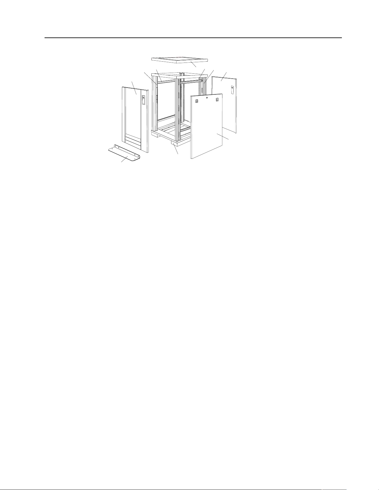
Parts Listing (Type 9306 Model 200)
10
9
8
7
1
2
3
4
5
6
Type 9306 Mod e l 200 47
Page 56

Index Rack Enclosure (Type 9306 Model 200) FRU
1 Top Cover including cover standoffs and screws 28L0548
2 Rear EIA Rail (1) includes mounting hardware 28L0547
3 Rack Frame 28L0550
Caster (1) 12J4466
Leveler (1) 76H4960
4 Rear Door Assembly including latch and lock 28L0545
5 Side Panel Assembly with Latches and Lo ck 28L0549
Side Panel Latches 12J4468
Side Panel Lock w ith Keys 76H4965
6 Caster Extension Plinth (1) 12J4482
7 Stabilizer 12J4485
8 Front Door Assembly including latch and lock 28L0544
9 Front EIA Rail (1) includes mounting hardware 28L0546
10 Side Brace (1) 12J4477
Front/Rear Door Hinge with Pin (1) 76H4966
Front/Rear Door Latch with Lock and Keys (1) 76H4967
Front/Rear Door Str ik e r Plat e (1) i n clu d es m ou n tin g hardw a re 12J4465
Front/Rear Door H ing e Pi n (1) 12J4469
Grommet, Cable Exit 28L0553
Label, EIA Unit Numbers 28L0551
Miscella ne ous Parts Kit - In cl udes: M6X25 Pan Head Screw (1), M6 Caged Nut (6), M6X16
Combinatio n Head Screw (6), 10-32 Flat W asher (6), M6X12 Button Socket Head Cap Screw
(5), 12mm Open End Wrench (1), M6 Tinnerman Clip (2), M6 Threaded Hex Spacer (1), M6
Dome Nut (2), M6 Flange Nut (5), Soft Tie Wraps (10)
Rack Enclosure (Type 9306 Model 200) Options FRU
Monitor Housing 76H4947
Filler Panels: 1U, 3U, and 5U - with hardware 12J4473
Keyboard T ray 76H4958
Keyboard Tray II 28L0562
Keyboard Tra y II filler block 28L0567
Keyboard Slides (set) with Hardware 76H4961
Fixed Shelf with Hardware 76H4963
76H4950
C13 - C14 Po wer Cable 07H0075
C19 - C14 Po wer Cable 76H4964
C13 - NEMA 5-15P Power Cable 76H4962
C19 - NEMA 5-15P Power C abl e 12J4479
Video, Mouse, Keyboard Cable (7 feet) 06P6006
48 Hardware Ma intena nce Manual: IBM PC Server/Enterprise Rack s
Page 57

Rack Enclosure (Type 9306 Model 200) Options FRU
Video, Mouse, Keyboard Cable (12 feet) 06P6007
Video, Mouse, Keyboar d Power Cable (25 feet) 12J4484
Mouse Extension Cable 07H0069
Keyboard Extensi on Cable 07H0067
Concentrator (4 port) with Hardware 28L0543
Concentrator (8 port) with Hardware 76H4948
1x4 switch 06P6003
2x8 switch 06P6004
NetB AY Rack Power D is tr ib u ti on U nit 09N9 6 68
NetBAY Front-end Power Distribution Unit 09N9670
3-phase NEMA L21-30P line cor d (200-250 Vac) for NetBAY Front-end PDU 24P6844
3-phase IEC 309-3P+N+Gnd line cord (380-4 15 Vac) for NetBAY Front-end PDU 24P6845
1-phase NEMA L5-30P line cord (100-127 Vac) for NetBAY Front-end PDU 24P6846
1-phase NEMA L6-30P line cord (200-240 Vac) for NetBAY Front-end PDU 24P6847
1-phase IEC 309-2P+Gnd line cord (200-240 Vac) for NetBAY Front-end PDU 24P6848
NetBAY Server Dual-cord Power Distribution Unit 09N9669
Hardware Kit for NetBAY Power Distribution Units 09N9671
Flat Panel Monitor R ack Mount Kit (T54A, models A G1, AW1; T55) 37L6888
Flat Panel Adapt e r H i nge - R.H. & L.H. (T54A, T55) 09N9678
Flat Panel Adap ter Misc. Har dw are Kit – I ncludes: Hin ge Cover (1), Power Suppl y Cover (1),
00N8693
Mounting Stud (1), Bumper (2), Cabl e Access Cover (1), M4 X 12 Scr ew (4), M4 X 8 Screw
(2), 14 inch Soft Tie Wrap (1), T54A power supply spacer (1)
Flat Panel Adapter Display Housing – Includes: Power Supply Cover (1), Base Housing (1),
00N8694
Cable Ac c ess Cover (1), Bottom Stand
Type 9306 Mod e l 200 49
Page 58

50 Hardware Ma intena nce Manual: IBM PC Server/Enterprise Rack s
Page 59

Type 9306 Model 900/910
Features. . . . . . . . . . . . . . . . . . . . . . . . . . . . . . . . . . . . 51
Locations. . . . . . . . . . . . . . . . . . . . . . . . . . . . . . . . . . . 51
Side Panel . . . . . . . . . . . . . . . . . . . . . . . . . . . . . . . . . . 51
Perforated Doors (model 910). . . . . . . . . . . . . . . . . 52
Installing the new door on a model 900 rack cabinet
53
Selector switch locations . . . . . . . . . . . . . . . . . . . . . 54
Power Distribution Unit. . . . . . . . . . . . . . . . . . . . . . 57
Blank bezel . . . . . . . . . . . . . . . . . . . . . . . . . . . . . . . . . 59
Fixed shelf . . . . . . . . . . . . . . . . . . . . . . . . . . . . . . . . . 59
Keyboard tray . . . . . . . . . . . . . . . . . . . . . . . . . . . . . . 60
Features
The IBM Server 9306-900/910 Rack enclosure is an industry-standard, 19-inch rack
that houses and controls multiple IBM PC Servers/IBM Servers and related
equipment.
• Model 900 has optional side panels, solid front door, and perforated rear door.
• Model 910 has s ide panels and perfora ted front and rear doors.
Locations
The following sections contain information on specific equipment locations.
Note: For instructions on how to power-off the rack, see “Powering off the rack” on
page 3.
Installing a flat panel monitor rack mount kit . . . 61
Removing the existing flat panel monitor stand . 61
Installing the new monitor stand. . . . . . . . . . . . . . 63
Starting the system. . . . . . . . . . . . . . . . . . . . . . . . . . 67
Configuring the selector switch . . . . . . . . . . . . . . . 67
Switching among servers . . . . . . . . . . . . . . . . . . . . 68
Advanced selector switch functions . . . . . . . . . . . 69
Resetting the selector switch. . . . . . . . . . . . . . . . . . 76
Making connections under power. . . . . . . . . . . . . 76
Parts listing (Type 9306 Model 900/910). . . . . . . . 77
Side Panel
© Copyright IBM Corp. 2001 51
Page 60

Locked Unlocked
®
Perforated Doors (model 910)
The Type 9306 Model 910 Rack comes with front and rear perforate d doors that
provide enhanced cooling and airflow for components you install in your rack
cabinet. The 9306 Model 910 Rack als o com e s with side panels already installed.
52 Hardware Ma intena nce Manual: IBM PC Server/Enterprise Rack s
Page 61
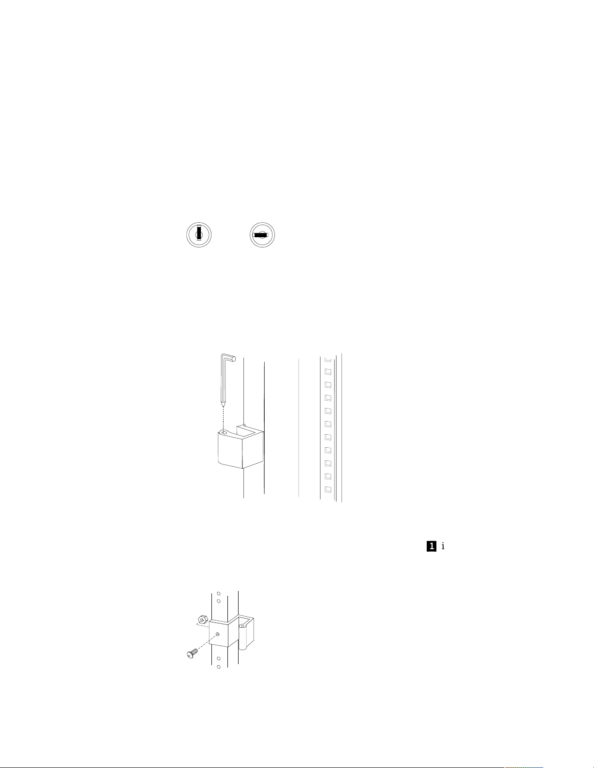
Refer to installation instructions in this doc u men t if you have a 9306 Model 900 Rack
and are installing a new perforated front door.
Note: The illustrations in this documentation might be slightly different from your
hardware.
Installing the new door on a model 900 rack cabinet
Use the following steps to remove your existing front door and install the new
perforated door:
1. Refer to th e rack documentation for information on removing side pane ls; then,
remove the left side panel on the rack and set it aside.
2. If the front door is locked, unlock it; then, open the front door.
Locked Unlocked
3. While supporting the door, remove all four hinge pins that hold the front door in
place; then, store the door in a safe place for possible future use.
Note: Save three of the hinge pins for later installation.
s
4. Remove the screw and nut that holds the hinge bracket c1d in place; then, move
the hinge bracket three mounting spaces downward and reinstall it at the new
center l o ca t i on .
Type 9306 Mod el 900/910 53
Page 62

®
Note: Insert the screw through the bracket and into the lo wer of the two holes in
the new center location.
5. Remove the other hi nge bracket
c3d
and store it with the old door that you
removed earlier.
6. While supporting the new door, use three of the hinge pins that you removed
from the old door to attach the new door to your rack cabinet. Store the fourth
hinge pin with the old door and hinge bracket.
7. Reinstall the lef t side panel th at you remov e d earlie r.
Selector switch locations
Note: For information about the IBM NetBAY Console Switch, see “IBM NetBAY
console switch” on page 129.
1
n
0
t
tio
e
e
r
a
h
T
rtan
o
po
Tw
Inform
M
Im
e
K
e
r
h
T
M
e
K
e
r
h
T
M
K
o
Tw
M
e
K
e
r
h
T
M
K
o
Tw
M
K
e
n
O
M
K
t
e
s
e
R
M
K
.
x
u
A
Figure 19 . Selector switc h in monitor compart ment
54 Hardware Ma intena nce Manual: IBM PC Server/Enterprise Rack s
Page 63

FRONT
0
1
Inform
ation
Im
po
rtant
M
K
Three
M
K
Two
M
K
Three
M
K
Three
M
K
Two
M
K
Three
M
K
Two
M
K
One
Aux.
Reset
REAR
Figure 20. Selector switch between side panels
Figure 21. Selector switch rear of rack with blank panel front of rack
Type 9306 Mod el 900/910 55
Page 64
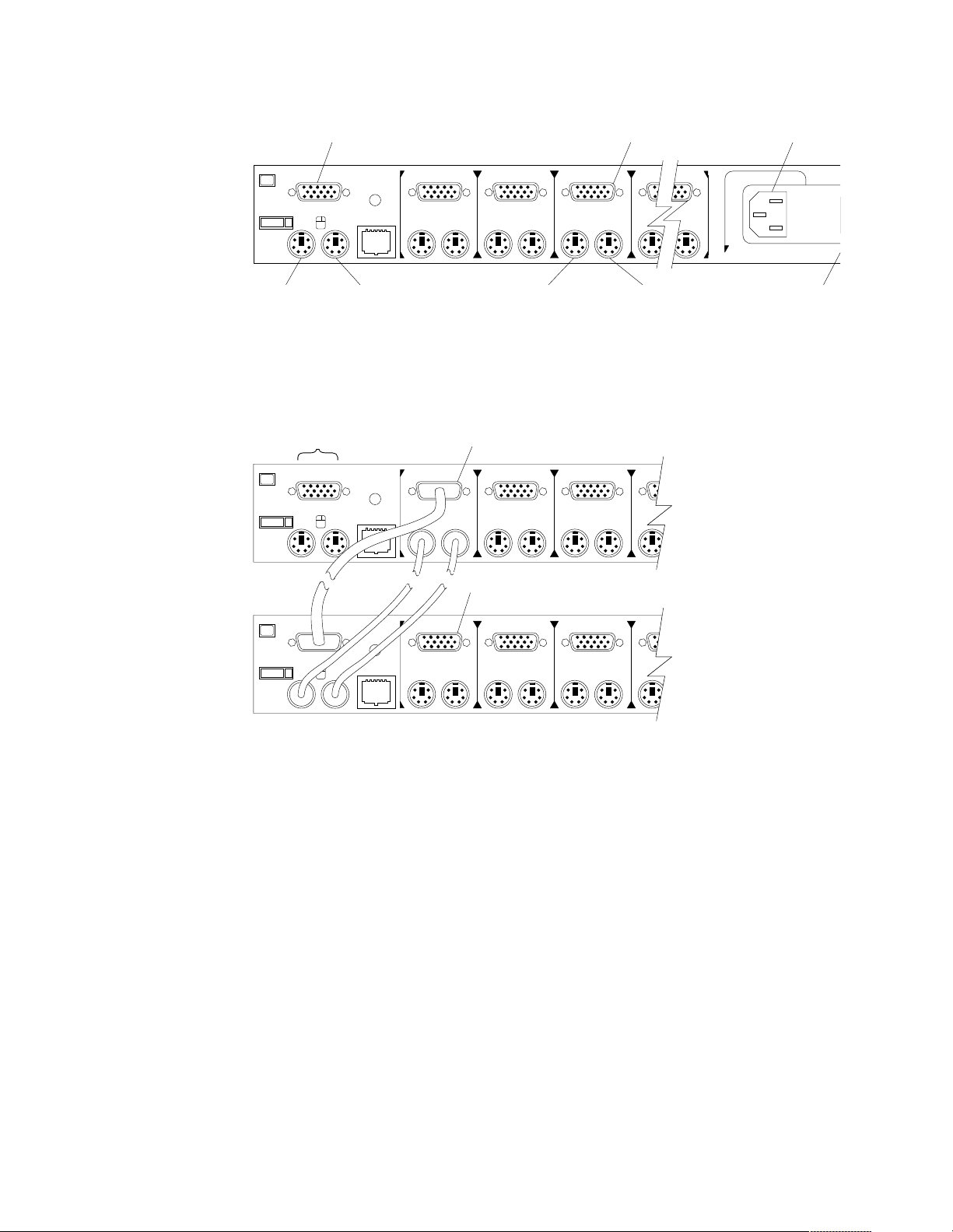
o
o
Selector switch cable connections:
Monitor
Computer 3
Monitor
Power C
Connect
One
KM
Keyboard
Reset
Aux.
Mouse
Tiered switch configuration:
Monitor
Keyboard
Mouse
Connectors
Reset
Aux.
Reset
One
KM
One
Two
Computer 3
Keyboard
System 1 to 8
Two
System 1-1 to 1-8
Two
Three
KM
Three
KM
Three
KMKM
Computer 3
Mouse
KKM
Important
Information
Power
Switch
Aux.
KM
KM
KKM
One eight-port primary selector switch can accommodate up to eight secondary
selector switches which can then support up to 64 servers.
Note: There are two types of selector switches available:
• 4 port
• 8 port
56 Hardware Ma intena nce Manual: IBM PC Server/Enterprise Rack s
Page 65

Selector switch environment:
Monitor
Console
Cable
Set
Keyboard Mouse
Selector Switch
Server 1
Server 2
Server 3
Server 4
Figure 22 . Single se lect or switch
Monitor
Primary Selector Switch
Console
Cable
Set
Keyboard Mouse
Server 1
Server 2
Server 3
Secondary Selector Switch
Server 4
Server 5
Figure 23 . M ultiple selecto r switch
Power Distribution Unit
Note: For information and installation instructi ons for the IBM NetBAY Rack Power
Distribu tion Units, see “Net BAY Power Distribution Units” on page 141.
Type 9306 Mod el 900/910 57
Page 66

REAR
Figure 24. P ower Dis tributi on instal lation
FRONT
Figure 25. Power Distribution horizontal installation
Note: There are two types of Power distrib ution units available:
• High voltage
• Low voltage
58 Hardware Ma intena nce Manual: IBM PC Server/Enterprise Rack s
Page 67

Blank bezel
Fixed shelf
Type 9306 Mod el 900/910 59
Page 68

Keyboard t ray
To remove the tray from the side rails, pul l up on the left rail tab and push down on
the rig ht ra i l ta b .
60 Hardware Ma intena nce Manual: IBM PC Server/Enterprise Rack s
Page 69

Installing a flat panel monitor rack mount kit
You can store a T54 or T55 Flat Panel Monitor in a keybo ard tray with the flat panel
monitor rack mount kit . This kit r equ ires an addition al 2U of space abo ve an inst alled
keyboard tray in your rack cab inet. See the docu me ntation that comes with the flat
panel monitor rack mount kit for detailed installation instructions. Use the following
general procedure to install a flat panel monitor in your rack cabinet:
Flat panel monitor
Rear screws
Mounting studs
Bumpers
Keyboard tray
Figure 26. Installing a flat panel monitor rack mount kit
1. Ensure that a keyboard tray is properly installed in your rack cabinet (see
“Keyboard tray” on page 60) with at least 2U of clearance above the keyboar d
tray.
2. Install the flat panel monitor base on the flat panel monitor. See the
documentation that comes with you r flat panel monitor r a ck mount kit for
detailed installat io n instruct ions .
3. Install the mounting studs and bu mp e rs on the keyboard tray.
4. Attach the monitor base to the inside of the keyboard tray using the screws that
come with the rack mount kit.
5. Fold the monitor all the way down against the bumpers; then, slide the keyboard
tray into the rack cabinet to ensure that there is proper clearance.
6. See the documentation that comes with your flat panel monitor for information
on how to connect power and how to connect the monitor to a server or console
switch.
Removing the existing flat panel monitor stand
Use the following steps to remove the existing flat panel monitor stand from your
monitor:
Type 9306 Mod el 900/910 61
Page 70

1. Unplug the flat panel monitor and disconnect the power cord from the flat panel
monitor power supply.
2. Carefully use a flat-blade screwdriver to pry the bottom of the cable cover
and remove it. Save the cable cover for later reinstallation.
Figure 27. Removing the cable cover, hinge cover, and stand cover
3. Squeeze the sides of the hinge cover
Note: Even though this hinge cover is not used wi th the Flat Panel Monitor Rack
Mount Kit, do not discard it. Store it with the other monit or stand parts
you remove for possible future use.
4. Gently push the stand cover
the stand.
5. Disconnect the si gnal cable and power cor d from the flat panel monit or. Carefully
remove and save the plastic cable clamp to free the power cord.
Note: The plastic cable clamp is reusable and is needed to secure the power cord
after installing the Flat Panel Monitor Rack Mount Kit on the flat panel
monitor.
c3d
c2d
and remove it.
and slide it backwards until it is completely off
c1d
up
Figure 28. Removing the plastic cable clamp
6. Lay the monitor facedown on a cushioned surface and remove the six screws that
secure the hinges to the flat panel monitor.
62 Hardware Ma intena nce Manual: IBM PC Server/Enterprise Rack s
Page 71

Figure 29. Removing the existing monitor stand from the monitor
7. Lift off the hinge and monitor stand assembly. Store this assembly in a safe place
for possible future use.
Installing the new monitor stand
Refer to “Removing the existing flat panel monitor stand” on page 61 for instructions
on how to remove the existing stand from the flat panel monitor. Before installing the
new stand, install the keyboard tray in the rack according to the instructions that
come with th e rack or the keyboa rd tray option.
Note: The Flat Panel Monitor Rack Mount Kit and keyboard tray require 3U of rack
mounting space. If the keyboard tray does not have at least 2U of clearance
above it, relocate the keyboard tray within the rack.
Use the following steps to install the Flat Panel Monitor Rack Mount Kit:
1. Remove the cable cover
screws (two per hinge) that secure the hinges
c1d
from the new monitor stand; then, remove the four
c2d
to the stand.
Figure 30. Removing the hinges from the new monitor stand
2. Install the hinges on the flat panel monitor, using the six screws that you removed
from the old monitor stand.
Type 9306 Mod el 900/910 63
Page 72

Figure 31. Installing the hinges on the flat panel monitor
Note: Be sure to slide eac h hinge into place on the back of the monitor and align
the holes in the hinges with holes on the monitor.
3. Lower the flat panel monitor onto the new monitor stand, making sure that you
align the holes in the stand with holes in the hinges; then, secure the flat panel
monitor to the monitor stand with the four screws that you removed earlier.
Figure 32. Installing the monitor on the new monitor stand
You have now finished attaching the flat panel monitor to its stand. The rest of
the installation process involves prepar ing the keyboard tray for storage and
rou tin g cable s.
Notes:
a. You must r e move any keyboar d or mouse that i s already in the keyboard tray
before continuing.
b. You will not be able to store a mouse in the keyboard tray after installing the
Flat Panel Monitor Rack Mount Kit.
c. You can only store a space-saver keyboard in the keyboard tray.
4. Install the mounting studs
mounting hardware package.
c2d
and bumpers c3d that come in the monitor
64 Hardware Ma intena nce Manual: IBM PC Server/Enterprise Rack s
Page 73

Figure 33. Installing the flat panel monitor in the keyboard tray
Note: Clean the installation area on the keyboard tray with a suitable cleaning
agent, such as alcohol, before installing the rubber bumpers on the front of
the keyboar d tray.
5. Open the flat pan el monito r
the stand with the mounting s tu ds
c1d
to its full upright position and align the grooves in
c2d
in the keyboard tray. When the monitor
stand is sitting inside the keyboard tray, slide it towards the back until it stops.
Note: Install or remove the flat panel monitor only when the display is in its
upright position.
6. Secure th e monitor stand in the back of the keyboard tray with the two provided
screws
c4d
.
7. Place the flat panel monitor power supply, which came with your flat panel
monitor, inside the monitor stand. If necessary, insert the power supply spacer
c3d
behind the power supply and over the cable to keep the power supply in
place.
Type 9306 Mod el 900/910 65
Page 74

Figure 34. Storing the power supply and routing cables
8. Connect the power supply to the monitor and route the cable under the tab near
the top of the monitor stand
clamp you removed from the original stan d and coil excess cabl e in side the
monitor stand.
9. Connect the mon itor signal cab le to the monitor and route it under the tab in the
bottom of the m onitor sta n d
provided.
10. Replace the monitor stand cover
c1d
; then, secure the power cable with the cable
c2d
and ou t th e ba ck of the stand th rou gh the hol e
c1d
.
Figure 35. Installing the cable cover, hinge cover, and stand cover
11. Snap the new hinge cover
Note: Be sure to use the new hinge cover that comes with the Flat Panel Monitor
Rack Mount Kit because it has deeper grooves to accommodate the new
hinge assembly.
New hinge cover Old hinge cover
12. Snap the cable cover
13. Fold the flat panel monitor do wn until it rests o n the rubber bumpers; then, gently
push back and remove the small cable exit cover
c2d
into place over the hinge assembly.
c3d
into place on the back of the flat panel monitor .
c1d
on the monitor stand.
66 Hardware Ma intena nce Manual: IBM PC Server/Enterprise Rack s
Page 75

Figure 36. Routing the keyboard cable
14. Route the space-saver keyboard cabl e thro ugh the hole in t he front o f the base an d
out the opening in the back where you removed the small cover; then, place the
keyboard (with its adjustable feet fully down) inside the keyboard tray .
Note: You must open the flat panel monitor to its full upright position so that
you can install the keyboard and route its cable.
15. Fold the flat panel monitor down again until it rest s on the rubber bumpers; then,
reinstall the small cable exit cover
16. Slide the keyboard tray i nto the rack; t hen, neat ly route and secure all cables in the
rack using the provided cable straps.
You can now connect the power cord to the flat panel monitor and connect the
display to a server.
c1d
.
Starting the system
Start the system by:
1. Power-on the selector switch(s).
2. Power-on the monitor.
3. Power-on the servers.
Note: The selector switch must be powered on first, then the servers. This is to
assure that the device drivers for the servers send device settings to the
selector switch.
When the selector switch is powered on, it:
• Identifies the mouse and keyboard and puts them into default status.
• Switches to port 1 by default, and displays the number '1' in the status flag field
on the monitor.
Configuring the selector switch
Note: For information about the IBM NetBAY Console Switch, see “IBM NetBAY
console switch” on page 129.
Note: Some selector switch units have dif f e rent funct ions and displays. Refer to the
Apex PC Sol utions® Outlook™ Concentrator User Guide. This guide is
shipped with the selector switch unit.
No configuration is necessary for norma l swit ch operati on.
Type 9306 Mod el 900/910 67
Page 76

Switch configuration can be performed to:
• Assign unique names to servers.
• Display servers by their assi gned port names and port numbers.
Switching among servers
To switch among servers:
• Press the Print Screen key.
• Type the port number of the server to be switched.
• Press Ente r.
Note: One depression of the Print Screen key starts the switching process. To
print a screen, depress the Print Screen key twice.
Port Name
Port Name
Port Name
Port Name
Port Name
Port Name
Port Name
Port Name
Port Name
Port Name
Port Name
Port Name
Port Name
Port Name
Port Name
Port Name
Port Name
Port Name
Port Name
Port Name
Port Name
Port Name
Port Name
Port Name
Port Name
Port Name
Port Name
Port Name
Port Name
Port Name
1 Magic +
1 Magic +
1 Magic +
1 Magic +
1 Magic +
1 Magic +
1 Magic +
1 Magic +
1 Magic +
1 Magic +
1 Magic +
1 Magic +
1 Magic +
1 Magic +
1 Magic +
1 Magic +
1 Magic +
1 Magic +
1 Magic +
1 Magic +
1 Magic +
1 Magic +
1 Magic +
1 Magic +
1 Magic +
1 Magic +
1 Magic +
1 Magic +
1 Magic +
1 Magic +
2 CentralOfc +
2 CentralOfc +
2 CentralOfc +
2 CentralOfc +
2 CentralOfc +
2 CentralOfc +
2 CentralOfc +
2 CentralOfc +
2 CentralOfc +
2 CentralOfc +
2 CentralOfc +
2 CentralOfc +
2 CentralOfc +
2 CentralOfc +
2 CentralOfc +
2 CentralOfc +
2 CentralOfc +
2 CentralOfc +
2 CentralOfc +
2 CentralOfc +
2 CentralOfc +
2 CentralOfc +
2 CentralOfc +
2 CentralOfc +
2 CentralOfc +
2 CentralOfc +
2 CentralOfc +
2 CentralOfc +
2 CentralOfc +
2 CentralOfc +
3 Sales-C +
3 Sales-C +
3 Sales-C +
3 Sales-C +
3 Sales-C +
3 Sales-C +
3 Sales-C +
3 Sales-C +
3 Sales-C +
3 Sales-C +
3 Sales-C +
3 Sales-C +
3 Sales-C +
3 Sales-C +
3 Sales-C +
3 Sales-C +
3 Sales-C +
3 Sales-C +
3 Sales-C +
3 Sales-C +
3 Sales-C +
3 Sales-C +
3 Sales-C +
3 Sales-C +
3 Sales-C +
3 Sales-C +
3 Sales-C +
3 Sales-C +
3 Sales-C +
3 Sales-C +
4 Sales-B
4 Sales-B
4 Sales-B
4 Sales-B
4 Sales-B
4 Sales-B
4 Sales-B
4 Sales-B
4 Sales-B
4 Sales-B
4 Sales-B
4 Sales-B
4 Sales-B
4 Sales-B
4 Sales-B
4 Sales-B
4 Sales-B
4 Sales-B
4 Sales-B
4 Sales-B
4 Sales-B
4 Sales-B
4 Sales-B
4 Sales-B
4 Sales-B
4 Sales-B
4 Sales-B
4 Sales-B
4 Sales-B
4 Sales-B
5 Sales-A +
5 Sales-A +
5 Sales-A +
5 Sales-A +
5 Sales-A +
5 Sales-A +
5 Sales-A +
5 Sales-A +
5 Sales-A +
5 Sales-A +
5 Sales-A +
5 Sales-A +
5 Sales-A +
5 Sales-A +
5 Sales-A +
5 Sales-A +
5 Sales-A +
5 Sales-A +
5 Sales-A +
5 Sales-A +
5 Sales-A +
5 Sales-A +
5 Sales-A +
5 Sales-A +
5 Sales-A +
5 Sales-A +
5 Sales-A +
5 Sales-A +
5 Sales-A +
5 Sales-A +
6 Downtown
6 Downtown
6 Downtown
6 Downtown
6 Downtown
6 Downtown
6 Downtown
6 Downtown
6 Downtown
6 Downtown
6 Downtown
6 Downtown
6 Downtown
6 Downtown
6 Downtown
6 Downtown
6 Downtown
6 Downtown
6 Downtown
6 Downtown
6 Downtown
6 Downtown
6 Downtown
6 Downtown
6 Downtown
6 Downtown
6 Downtown
6 Downtown
6 Downtown
6 Downtown
7 Foreign +
7 Foreign +
7 Foreign +
7 Foreign +
7 Foreign +
7 Foreign +
7 Foreign +
7 Foreign +
7 Foreign +
7 Foreign +
7 Foreign +
7 Foreign +
7 Foreign +
7 Foreign +
7 Foreign +
7 Foreign +
7 Foreign +
7 Foreign +
7 Foreign +
7 Foreign +
7 Foreign +
7 Foreign +
7 Foreign +
7 Foreign +
7 Foreign +
7 Foreign +
7 Foreign +
7 Foreign +
7 Foreign +
7 Foreign +
8
8
8
8
8
8
8
8
8
8
8
8
8
8
8
8
8
8
8
8
8
8
8
8
8
8
8
8
8
8
F1 Help F2 Advanced
F1 Help F2 Advanced
F1 Help F2 Advanced
F1 Help F2 Advanced
F1 Help F2 Advanced
F1 Help F2 Advanced
F1 Help F2 Advanced
F1 Help F2 Advanced
F1 Help F2 Advanced
F1 Help F2 Advanced
F1 Help F2 Advanced
F1 Help F2 Advanced
F1 Help F2 Advanced
F1 Help F2 Advanced
F1 Help F2 Advanced
F1 Help F2 Advanced
F1 Help F2 Advanced
F1 Help F2 Advanced
F1 Help F2 Advanced
F1 Help F2 Advanced
F1 Help F2 Advanced
F1 Help F2 Advanced
F1 Help F2 Advanced
F1 Help F2 Advanced
F1 Help F2 Advanced
F1 Help F2 Advanced
F1 Help F2 Advanced
F1 Help F2 Advanced
F1 Help F2 Advanced
F1 Help F2 Advanced
68 Hardware Ma intena nce Manual: IBM PC Server/Enterprise Rack s
Page 77

Port Name
Port Name
Port Name
Port Name
Port Name
Port Name
Port Name
Port Name
Port Name
Port Name
Port Name
Port Name
Port Name
Port Name
Port Name
Port Name
Port Name
Port Name
Port Name
Port Name
Port Name
Port Name
Port Name
Port Name
Port Name
Port Name
Port Name
Port Name
Port Name
Port Name
CentralOfc 2 +
CentralOfc 2 +
CentralOfc 2 +
CentralOfc 2 +
CentralOfc 2 +
CentralOfc 2 +
CentralOfc 2 +
CentralOfc 2 +
CentralOfc 2 +
CentralOfc 2 +
CentralOfc 2 +
CentralOfc 2 +
CentralOfc 2 +
CentralOfc 2 +
CentralOfc 2 +
CentralOfc 2 +
CentralOfc 2 +
CentralOfc 2 +
CentralOfc 2 +
CentralOfc 2 +
CentralOfc 2 +
CentralOfc 2 +
CentralOfc 2 +
CentralOfc 2 +
CentralOfc 2 +
CentralOfc 2 +
CentralOfc 2 +
CentralOfc 2 +
CentralOfc 2 +
CentralOfc 2 +
Downtown 6
Downtown 6
Downtown 6
Downtown 6
Downtown 6
Downtown 6
Downtown 6
Downtown 6
Downtown 6
Downtown 6
Downtown 6
Downtown 6
Downtown 6
Downtown 6
Downtown 6
Downtown 6
Downtown 6
Downtown 6
Downtown 6
Downtown 6
Downtown 6
Downtown 6
Downtown 6
Downtown 6
Downtown 6
Downtown 6
Downtown 6
Downtown 6
Downtown 6
Downtown 6
Foreign 7 +
Foreign 7 +
Foreign 7 +
Foreign 7 +
Foreign 7 +
Foreign 7 +
Foreign 7 +
Foreign 7 +
Foreign 7 +
Foreign 7 +
Foreign 7 +
Foreign 7 +
Foreign 7 +
Foreign 7 +
Foreign 7 +
Foreign 7 +
Foreign 7 +
Foreign 7 +
Foreign 7 +
Foreign 7 +
Foreign 7 +
Foreign 7 +
Foreign 7 +
Foreign 7 +
Foreign 7 +
Foreign 7 +
Foreign 7 +
Foreign 7 +
Foreign 7 +
Foreign 7 +
Magic 1 +
Magic 1 +
Magic 1 +
Magic 1 +
Magic 1 +
Magic 1 +
Magic 1 +
Magic 1 +
Magic 1 +
Magic 1 +
Magic 1 +
Magic 1 +
Magic 1 +
Magic 1 +
Magic 1 +
Magic 1 +
Magic 1 +
Magic 1 +
Magic 1 +
Magic 1 +
Magic 1 +
Magic 1 +
Magic 1 +
Magic 1 +
Magic 1 +
Magic 1 +
Magic 1 +
Magic 1 +
Magic 1 +
Magic 1 +
Sales-A 5 +
Sales-A 5 +
Sales-A 5 +
Sales-A 5 +
Sales-A 5 +
Sales-A 5 +
Sales-A 5 +
Sales-A 5 +
Sales-A 5 +
Sales-A 5 +
Sales-A 5 +
Sales-A 5 +
Sales-A 5 +
Sales-A 5 +
Sales-A 5 +
Sales-A 5 +
Sales-A 5 +
Sales-A 5 +
Sales-A 5 +
Sales-A 5 +
Sales-A 5 +
Sales-A 5 +
Sales-A 5 +
Sales-A 5 +
Sales-A 5 +
Sales-A 5 +
Sales-A 5 +
Sales-A 5 +
Sales-A 5 +
Sales-A 5 +
Sales-B 4
Sales-B 4
Sales-B 4
Sales-B 4
Sales-B 4
Sales-B 4
Sales-B 4
Sales-B 4
Sales-B 4
Sales-B 4
Sales-B 4
Sales-B 4
Sales-B 4
Sales-B 4
Sales-B 4
Sales-B 4
Sales-B 4
Sales-B 4
Sales-B 4
Sales-B 4
Sales-B 4
Sales-B 4
Sales-B 4
Sales-B 4
Sales-B 4
Sales-B 4
Sales-B 4
Sales-B 4
Sales-B 4
Sales-B 4
Sales-C 3 +
Sales-C 3 +
Sales-C 3 +
Sales-C 3 +
Sales-C 3 +
Sales-C 3 +
Sales-C 3 +
Sales-C 3 +
Sales-C 3 +
Sales-C 3 +
Sales-C 3 +
Sales-C 3 +
Sales-C 3 +
Sales-C 3 +
Sales-C 3 +
Sales-C 3 +
Sales-C 3 +
Sales-C 3 +
Sales-C 3 +
Sales-C 3 +
Sales-C 3 +
Sales-C 3 +
Sales-C 3 +
Sales-C 3 +
Sales-C 3 +
Sales-C 3 +
Sales-C 3 +
Sales-C 3 +
Sales-C 3 +
Sales-C 3 +
8
8
8
8
8
8
8
8
8
8
8
8
8
8
8
8
8
8
8
8
8
8
8
8
8
8
8
8
8
8
F1 Help F2 Advanced
F1 Help F2 Advanced
F1 Help F2 Advanced
F1 Help F2 Advanced
F1 Help F2 Advanced
F1 Help F2 Advanced
F1 Help F2 Advanced
F1 Help F2 Advanced
F1 Help F2 Advanced
F1 Help F2 Advanced
F1 Help F2 Advanced
F1 Help F2 Advanced
F1 Help F2 Advanced
F1 Help F2 Advanced
F1 Help F2 Advanced
F1 Help F2 Advanced
F1 Help F2 Advanced
F1 Help F2 Advanced
F1 Help F2 Advanced
F1 Help F2 Advanced
F1 Help F2 Advanced
F1 Help F2 Advanced
F1 Help F2 Advanced
F1 Help F2 Advanced
F1 Help F2 Advanced
F1 Help F2 Advanced
F1 Help F2 Advanced
F1 Help F2 Advanced
F1 Help F2 Advanced
F1 Help F2 Advanced
• Using the Up Arrow (h and Down Arrow (d), select th e se rver you want to
switch to, or press the numeric key that corresponds to the server’s port number
and then press Enter.
The symbol s after the Port or Name columns on the menu show the status of the port
as follows:
Type of Symbol Symbol Meaning
Plus + Server connected and running
Asterisk * Secondary selector switch connected and running
Advanced selector switch functions
System configuration is performed through the keyboard and menus to include these
advanced sel e ctor switch f unctions:
• Scanning the servers
• Displaying server BIOS versions and settings
• Saving the hardware configuration
• Resetting the mouse and keyboard
• Setting a scan pattern
• Assigning unique names to the servers
• Listing servers by name or port number (Changing Menu Attributes)
• Changing the posit ion and col or of the operation menus and windows (Cha nging
Flag Attributes)
• Assigning a specific monitor type to a certain port (server)
Scannin g th e servers: To place the se lector switch in scan mode:
• Press the Print Screen key.
Type 9306 Mod el 900/910 69
Page 78

• Press the F2 key to display the Advanced Menu screen.
• Using the Up Arrow (
Scan and press Enter. The selector switch enters the scan mode and the display
returns to the status flag. To cancel the operation, press Esc any time before you
press Enter.
• To cancel the scan mode, press any key or move the mouse. The scan stops at the
currently connected server.
Displaying version information and device settings: The selector switch BIOS
version number along with keyboard and mouse information can be displayed for the
currently selected server.
• Press the Print Screen key.
• Press the F2 key to display the Advanced Menu screen.
• Using the Up Arrow (
Version and press Enter.
Version
Version
Version
Version
Version
Version
Version
Version
Version
Version
Version
Version
Version
Version
Version
Version
Version
Version
Version
Version
Version
Version
Version
Version
Version
Version
Version
Version
Version
Version
BIOS X.XX
BIOS X.XX
BIOS X.XX
BIOS X.XX
BIOS X.XX
BIOS X.XX
BIOS X.XX
BIOS X.XX
BIOS X.XX
BIOS X.XX
BIOS X.XX
BIOS X.XX
BIOS X.XX
BIOS X.XX
BIOS X.XX
BIOS X.XX
BIOS X.XX
BIOS X.XX
BIOS X.XX
BIOS X.XX
BIOS X.XX
BIOS X.XX
BIOS X.XX
BIOS X.XX
BIOS X.XX
BIOS X.XX
BIOS X.XX
BIOS X.XX
BIOS X.XX
BIOS X.XX
Hardware X X
Hardware X X
Hardware X X
Hardware X X
Hardware X X
Hardware X X
Hardware X X
Hardware X X
Hardware X X
Hardware X X
Hardware X X
Hardware X X
Hardware X X
Hardware X X
Hardware X X
Hardware X X
Hardware X X
Hardware X X
Hardware X X
Hardware X X
Hardware X X
Hardware X X
Hardware X X
Hardware X X
Hardware X X
Hardware X X
Hardware X X
Hardware X X
Hardware X X
Hardware X X
h
) and Down Arrow (d) keys, move the highlighting to
h
) and Down Arrow (d) keys, move the highlighting to
Port 1 Magic 1
Port 1 Magic 1
Port 1 Magic 1
Port 1 Magic 1
Port 1 Magic 1
Port 1 Magic 1
Port 1 Magic 1
Port 1 Magic 1
Port 1 Magic 1
Port 1 Magic 1
Port 1 Magic 1
Port 1 Magic 1
Port 1 Magic 1
Port 1 Magic 1
Port 1 Magic 1
Port 1 Magic 1
Port 1 Magic 1
Port 1 Magic 1
Port 1 Magic 1
Port 1 Magic 1
Port 1 Magic 1
Port 1 Magic 1
Port 1 Magic 1
Port 1 Magic 1
Port 1 Magic 1
Port 1 Magic 1
Port 1 Magic 1
Port 1 Magic 1
Port 1 Magic 1
Port 1 Magic 1
Keyboard Mouse
Keyboard Mouse
Keyboard Mouse
Keyboard Mouse
Keyboard Mouse
Keyboard Mouse
Keyboard Mouse
Keyboard Mouse
Keyboard Mouse
Keyboard Mouse
Keyboard Mouse
Keyboard Mouse
Keyboard Mouse
Keyboard Mouse
Keyboard Mouse
Keyboard Mouse
Keyboard Mouse
Keyboard Mouse
Keyboard Mouse
Keyboard Mouse
Keyboard Mouse
Keyboard Mouse
Keyboard Mouse
Keyboard Mouse
Keyboard Mouse
Keyboard Mouse
Keyboard Mouse
Keyboard Mouse
Keyboard Mouse
Keyboard Mouse
Enabled Enabled
Enabled Enabled
Enabled Enabled
Enabled Enabled
Enabled Enabled
Enabled Enabled
Enabled Enabled
Enabled Enabled
Enabled Enabled
Enabled Enabled
Enabled Enabled
Enabled Enabled
Enabled Enabled
Enabled Enabled
Enabled Enabled
Enabled Enabled
Enabled Enabled
Enabled Enabled
Enabled Enabled
Enabled Enabled
Enabled Enabled
Enabled Enabled
Enabled Enabled
Enabled Enabled
Enabled Enabled
Enabled Enabled
Enabled Enabled
Enabled Enabled
Enabled Enabled
Enabled Enabled
Rate 2C Rate 100
Rate 2C Rate 100
Rate 2C Rate 100
Rate 2C Rate 100
Rate 2C Rate 100
Rate 2C Rate 100
Rate 2C Rate 100
Rate 2C Rate 100
Rate 2C Rate 100
Rate 2C Rate 100
Rate 2C Rate 100
Rate 2C Rate 100
Rate 2C Rate 100
Rate 2C Rate 100
Rate 2C Rate 100
Rate 2C Rate 100
Rate 2C Rate 100
Rate 2C Rate 100
Rate 2C Rate 100
Rate 2C Rate 100
Rate 2C Rate 100
Rate 2C Rate 100
Rate 2C Rate 100
Rate 2C Rate 100
Rate 2C Rate 100
Rate 2C Rate 100
Rate 2C Rate 100
Rate 2C Rate 100
Rate 2C Rate 100
Rate 2C Rate 100
LEDs 2 Res 2
LEDs 2 Res 2
LEDs 2 Res 2
LEDs 2 Res 2
LEDs 2 Res 2
LEDs 2 Res 2
LEDs 2 Res 2
LEDs 2 Res 2
LEDs 2 Res 2
LEDs 2 Res 2
LEDs 2 Res 2
LEDs 2 Res 2
LEDs 2 Res 2
LEDs 2 Res 2
LEDs 2 Res 2
LEDs 2 Res 2
LEDs 2 Res 2
LEDs 2 Res 2
LEDs 2 Res 2
LEDs 2 Res 2
LEDs 2 Res 2
LEDs 2 Res 2
LEDs 2 Res 2
LEDs 2 Res 2
LEDs 2 Res 2
LEDs 2 Res 2
LEDs 2 Res 2
LEDs 2 Res 2
LEDs 2 Res 2
LEDs 2 Res 2
Mode 2
Mode 2
Mode 2
Mode 2
Mode 2
Mode 2
Mode 2
Mode 2
Mode 2
Mode 2
Mode 2
Mode 2
Mode 2
Mode 2
Mode 2
Mode 2
Mode 2
Mode 2
Mode 2
Mode 2
Mode 2
Mode 2
Mode 2
Mode 2
Mode 2
Mode 2
Mode 2
Mode 2
Mode 2
Mode 2
Type 101 Type Gen
Type 101 Type Gen
Type 101 Type Gen
Type 101 Type Gen
Type 101 Type Gen
Type 101 Type Gen
Type 101 Type Gen
Type 101 Type Gen
Type 101 Type Gen
Type 101 Type Gen
Type 101 Type Gen
Type 101 Type Gen
Type 101 Type Gen
Type 101 Type Gen
Type 101 Type Gen
Type 101 Type Gen
Type 101 Type Gen
Type 101 Type Gen
Type 101 Type Gen
Type 101 Type Gen
Type 101 Type Gen
Type 101 Type Gen
Type 101 Type Gen
Type 101 Type Gen
Type 101 Type Gen
Type 101 Type Gen
Type 101 Type Gen
Type 101 Type Gen
Type 101 Type Gen
Type 101 Type Gen
Keyboard information includes:
— Enabled or disabled
— Typematic rate
— LED settings
— Port mode
— Keyboard type.
Mouse information includes:
— Enabled or disabled
— Sample rate
— Resolution
— Mouse type
• Press Esc to remove the Version menu.
70 Hardware Ma intena nce Manual: IBM PC Server/Enterprise Rack s
Page 79

Saving hardwa re configurat ion: Whenever servers are added to or removed from
the configuration, or whenever there is a change in the mouse or monitor, save the
hardware configuration setting by:
1. Press the Print Screen key.
2. Press the F2 key to display the Advanced Menu screen.
3. Using the Up Arrow (
h
) and Down Arrow (d) keys, move the highlighting to
Snapshot and press the Enter key. The hardware settings are saved to memory.
Important: If the settings are not saved and the selector switch power is lost, it might
be necessary to restart each server in the configuration to reestablish
keyboard and mouse communications.
Resetting the mouse and keyboard: Resetting the mouse and keyboard restores the
default se tting for the selected server.
• Press the Print Screen key.
• Press the F2 key to display the Advanced Menu screen.
• Using the Up Arrow (
h
) and Down Arrow (d) keys, move the highlighting to
Reset and press the Enter key. The mouse and keyboard are now reset.
Setting a scan pattern: The selector switch has a standard scan routine for
sequentially connecting each server to the monitor, keyboard, and mouse. The scan
routine can be configured to scan all or any of the servers in a particular pattern. To
create a scan pattern, do the following.
1. Press the Print Screen key.
2. Press the F2 key to display the Advanced Menu screen. Press the Right Arrow
(
g
) key to move the highlight to the Setup Menu .
3. Using the Up Arrow (
h
) and Down Arrow (d) keys, move the highlighting to
Scan and press the Enter key. The Scan Pattern Setup menu appears with the
first port position or server name highlighted. The following example screen
displays when the port order mode is selected.
Scan Pattern Setup
Scan Pattern Setup
Scan Pattern Setup
Scan Pattern Setup
Scan Pattern Setup
Scan Pattern Setup
Scan Pattern Setup
Scan Pattern Setup
Scan Pattern Setup
Scan Pattern Setup
Scan Pattern Setup
Scan Pattern Setup
Scan Pattern Setup
Scan Pattern Setup
Scan Pattern Setup
Scan Pattern Setup
Scan Pattern Setup
Scan Pattern Setup
Scan Pattern Setup
Scan Pattern Setup
Scan Pattern Setup
Scan Pattern Setup
Scan Pattern Setup
Scan Pattern Setup
Scan Pattern Setup
Scan Pattern Setup
Scan Pattern Setup
Scan Pattern Setup
Scan Pattern Setup
Scan Pattern Setup
Port/Sec Name
Port/Sec Name
Port/Sec Name
Port/Sec Name
Port/Sec Name
Port/Sec Name
Port/Sec Name
Port/Sec Name
Port/Sec Name
Port/Sec Name
Port/Sec Name
Port/Sec Name
Port/Sec Name
Port/Sec Name
Port/Sec Name
Port/Sec Name
Port/Sec Name
Port/Sec Name
Port/Sec Name
Port/Sec Name
Port/Sec Name
Port/Sec Name
Port/Sec Name
Port/Sec Name
Port/Sec Name
Port/Sec Name
Port/Sec Name
Port/Sec Name
Port/Sec Name
Port/Sec Name
6/20 Downtown
6/20 Downtown
6/20 Downtown
6/20 Downtown
6/20 Downtown
6/20 Downtown
6/20 Downtown
6/20 Downtown
6/20 Downtown
6/20 Downtown
6/20 Downtown
6/20 Downtown
6/20 Downtown
6/20 Downtown
6/20 Downtown
6/20 Downtown
6/20 Downtown
6/20 Downtown
6/20 Downtown
6/20 Downtown
6/20 Downtown
6/20 Downtown
6/20 Downtown
6/20 Downtown
6/20 Downtown
6/20 Downtown
6/20 Downtown
6/20 Downtown
6/20 Downtown
6/20 Downtown
5/20 Sales-A
5/20 Sales-A
5/20 Sales-A
5/20 Sales-A
5/20 Sales-A
5/20 Sales-A
5/20 Sales-A
5/20 Sales-A
5/20 Sales-A
5/20 Sales-A
5/20 Sales-A
5/20 Sales-A
5/20 Sales-A
5/20 Sales-A
5/20 Sales-A
5/20 Sales-A
5/20 Sales-A
5/20 Sales-A
5/20 Sales-A
5/20 Sales-A
5/20 Sales-A
5/20 Sales-A
5/20 Sales-A
5/20 Sales-A
5/20 Sales-A
5/20 Sales-A
5/20 Sales-A
5/20 Sales-A
5/20 Sales-A
5/20 Sales-A
4/10 Sales-B
4/10 Sales-B
4/10 Sales-B
4/10 Sales-B
4/10 Sales-B
4/10 Sales-B
4/10 Sales-B
4/10 Sales-B
4/10 Sales-B
4/10 Sales-B
4/10 Sales-B
4/10 Sales-B
4/10 Sales-B
4/10 Sales-B
4/10 Sales-B
4/10 Sales-B
4/10 Sales-B
4/10 Sales-B
4/10 Sales-B
4/10 Sales-B
4/10 Sales-B
4/10 Sales-B
4/10 Sales-B
4/10 Sales-B
4/10 Sales-B
4/10 Sales-B
4/10 Sales-B
4/10 Sales-B
4/10 Sales-B
4/10 Sales-B
1/10 Match
1/10 Match
1/10 Match
1/10 Match
1/10 Match
1/10 Match
1/10 Match
1/10 Match
1/10 Match
1/10 Match
1/10 Match
1/10 Match
1/10 Match
1/10 Match
1/10 Match
1/10 Match
1/10 Match
1/10 Match
1/10 Match
1/10 Match
1/10 Match
1/10 Match
1/10 Match
1/10 Match
1/10 Match
1/10 Match
1/10 Match
1/10 Match
1/10 Match
1/10 Match
F2 for defaults
F2 for defaults
F2 for defaults
F2 for defaults
F2 for defaults
F2 for defaults
F2 for defaults
F2 for defaults
F2 for defaults
F2 for defaults
F2 for defaults
F2 for defaults
F2 for defaults
F2 for defaults
F2 for defaults
F2 for defaults
F2 for defaults
F2 for defaults
F2 for defaults
F2 for defaults
F2 for defaults
F2 for defaults
F2 for defaults
F2 for defaults
F2 for defaults
F2 for defaults
F2 for defaults
F2 for defaults
F2 for defaults
F2 for defaults
If Name order was selected, the Port and Name columns will be reversed.
4. Using the keyboard keys, select the port number of the first server to be included
in the scan. Note that the server name, if any is assigned, appears in the far right
column on th e menu.
5. Press the Tab key or Right Arrow (
g
) key to move the highlighting to the Sec
column. Then, use the keyboard keys to enter a time value, in seconds, for the
Type 9306 Mod el 900/910 71
Page 80

length of time you want this server to be connected to the monitor and keyboard,
before switching to the next server in the scan.
6. Press the Down Arrow (
Port column and repeat step 5.
To delete unwanted ports from the scan list in the Scan Pattern Setup window,
place the highlighting on the top-most port to be removed and press the Delete
key (not the Del key on the numeric keypad).
7. When you have finished setting the scan pattern, press the Enter key. Press Esc at
any time before pressing Enter to retain the previous scan pattern.
Note: Pressing the F2 key will return all Port and Sec values to the factory
defaults.
8. To exit, press Esc.
Assign in g uni que name s to ser v ers: Unique names can be given to servers and
secondary selector switches. To assign names:
1. Press the Print Screen key.
2. Press the F2 key to display the Advanced Menu screen.
Press the Right Arrow (
3. Using the Up Arrow (
Names and press the Enter key. The Port Naming menu appears, as shown
below.
d
) key to move the highlighting to the next port in the
g
) key to move th e highlight to the Setup Menu.
h
) and Down Arrow (d) keys, move the highlighting to
Port Naming
Port Naming
Port Naming
Port Naming
Port Naming
Port Naming
Port Naming
Port Naming
Port Naming
Port Naming
Port Naming
Port Naming
Port Naming
Port Naming
Port Naming
Port Naming
Port Naming
Port Naming
Port Naming
Port Naming
Port Naming
Port Naming
Port Naming
Port Naming
Port Naming
Port Naming
Port Naming
Port Naming
Port Naming
Port Naming
Port Name
Port Name
Port Name
Port Name
Port Name
Port Name
Port Name
Port Name
Port Name
Port Name
Port Name
Port Name
Port Name
Port Name
Port Name
Port Name
Port Name
Port Name
Port Name
Port Name
Port Name
Port Name
Port Name
Port Name
Port Name
Port Name
Port Name
Port Name
Port Name
Port Name
1 MAGIC
1 MAGIC
1 MAGIC
1 MAGIC
1 MAGIC
1 MAGIC
1 MAGIC
1 MAGIC
1 MAGIC
1 MAGIC
1 MAGIC
1 MAGIC
1 MAGIC
1 MAGIC
1 MAGIC
1 MAGIC
1 MAGIC
1 MAGIC
1 MAGIC
1 MAGIC
1 MAGIC
1 MAGIC
1 MAGIC
1 MAGIC
1 MAGIC
1 MAGIC
1 MAGIC
1 MAGIC
1 MAGIC
1 MAGIC
2 CENTRALOFC
2 CENTRALOFC
2 CENTRALOFC
2 CENTRALOFC
2 CENTRALOFC
2 CENTRALOFC
2 CENTRALOFC
2 CENTRALOFC
2 CENTRALOFC
2 CENTRALOFC
2 CENTRALOFC
2 CENTRALOFC
2 CENTRALOFC
2 CENTRALOFC
2 CENTRALOFC
2 CENTRALOFC
2 CENTRALOFC
2 CENTRALOFC
2 CENTRALOFC
2 CENTRALOFC
2 CENTRALOFC
2 CENTRALOFC
2 CENTRALOFC
2 CENTRALOFC
2 CENTRALOFC
2 CENTRALOFC
2 CENTRALOFC
2 CENTRALOFC
2 CENTRALOFC
2 CENTRALOFC
3 SALES-C
3 SALES-C
3 SALES-C
3 SALES-C
3 SALES-C
3 SALES-C
3 SALES-C
3 SALES-C
3 SALES-C
3 SALES-C
3 SALES-C
3 SALES-C
3 SALES-C
3 SALES-C
3 SALES-C
3 SALES-C
3 SALES-C
3 SALES-C
3 SALES-C
3 SALES-C
3 SALES-C
3 SALES-C
3 SALES-C
3 SALES-C
3 SALES-C
3 SALES-C
3 SALES-C
3 SALES-C
3 SALES-C
3 SALES-C
4 SALES-B
4 SALES-B
4 SALES-B
4 SALES-B
4 SALES-B
4 SALES-B
4 SALES-B
4 SALES-B
4 SALES-B
4 SALES-B
4 SALES-B
4 SALES-B
4 SALES-B
4 SALES-B
4 SALES-B
4 SALES-B
4 SALES-B
4 SALES-B
4 SALES-B
4 SALES-B
4 SALES-B
4 SALES-B
4 SALES-B
4 SALES-B
4 SALES-B
4 SALES-B
4 SALES-B
4 SALES-B
4 SALES-B
4 SALES-B
5 SALES-A
5 SALES-A
5 SALES-A
5 SALES-A
5 SALES-A
5 SALES-A
5 SALES-A
5 SALES-A
5 SALES-A
5 SALES-A
5 SALES-A
5 SALES-A
5 SALES-A
5 SALES-A
5 SALES-A
5 SALES-A
5 SALES-A
5 SALES-A
5 SALES-A
5 SALES-A
5 SALES-A
5 SALES-A
5 SALES-A
5 SALES-A
5 SALES-A
5 SALES-A
5 SALES-A
5 SALES-A
5 SALES-A
5 SALES-A
6 DOWNTOWN
6 DOWNTOWN
6 DOWNTOWN
6 DOWNTOWN
6 DOWNTOWN
6 DOWNTOWN
6 DOWNTOWN
6 DOWNTOWN
6 DOWNTOWN
6 DOWNTOWN
6 DOWNTOWN
6 DOWNTOWN
6 DOWNTOWN
6 DOWNTOWN
6 DOWNTOWN
6 DOWNTOWN
6 DOWNTOWN
6 DOWNTOWN
6 DOWNTOWN
6 DOWNTOWN
6 DOWNTOWN
6 DOWNTOWN
6 DOWNTOWN
6 DOWNTOWN
6 DOWNTOWN
6 DOWNTOWN
6 DOWNTOWN
6 DOWNTOWN
6 DOWNTOWN
6 DOWNTOWN
7 FOREIGN
7 FOREIGN
7 FOREIGN
7 FOREIGN
7 FOREIGN
7 FOREIGN
7 FOREIGN
7 FOREIGN
7 FOREIGN
7 FOREIGN
7 FOREIGN
7 FOREIGN
7 FOREIGN
7 FOREIGN
7 FOREIGN
7 FOREIGN
7 FOREIGN
7 FOREIGN
7 FOREIGN
7 FOREIGN
7 FOREIGN
7 FOREIGN
7 FOREIGN
7 FOREIGN
7 FOREIGN
7 FOREIGN
7 FOREIGN
7 FOREIGN
7 FOREIGN
7 FOREIGN
8
8
8
8
8
8
8
8
8
8
8
8
8
8
8
8
8
8
8
8
8
8
8
8
8
8
8
8
8
8
4. Move the highlighting to the Port entry for which the server n ame i s t o be entered
or changed. Type in the name of the server using up to 12 alphanumeric
characters.
Note: Legal characters are A-Z, 0-9, and the dash character. Lowercase letters
are converted to uppercase. Press the Backs pace key t o d el ete an incorrect
entry.
5. If necessary, repeat step 4 for each of the servers that are to be named.
6. Press the Enter key to save the server names in nonvolatile RAM. Press Esc at any
time before pressing Enter to cancel the operation.
7. To exit, press Esc.
72 Hardware Ma intena nce Manual: IBM PC Server/Enterprise Rack s
Page 81

Changing menu attributes: The menus displayed on the monitor can be altered in
visual appearance to suit the particular use of the system. You can:
• Position the menu in a convenient location on the display.
• List servers by port or by name, whichever is desired, in the appropriate menus.
• Adjust character height.
• Change c o lors.
• Display the selection menu for a certain period.
To change the menu attributes, do the following:
• Press the Print Screen key.
• Press the F2 key to display the Advanced Menu screen. Press the Right Arrow
(
g
) key to mo ve the high li gh t i n g to the Setu p li s t.
• Using the Up Arrow (
h
) and Down Arrow (d) keys, move the highlighting to
OSCAR™. (On Screen Configuration and Activity Reporting) and press the
Enter key. The following Attribute menu appears.
OSCAR Attributes
OSCAR Attributes
OSCAR Attributes
OSCAR Attributes
OSCAR Attributes
OSCAR Attributes
OSCAR Attributes
OSCAR Attributes
OSCAR Attributes
OSCAR Attributes
OSCAR Attributes
OSCAR Attributes
OSCAR Attributes
OSCAR Attributes
OSCAR Attributes
OSCAR Attributes
OSCAR Attributes
OSCAR Attributes
OSCAR Attributes
OSCAR Attributes
OSCAR Attributes
OSCAR Attributes
OSCAR Attributes
OSCAR Attributes
OSCAR Attributes
OSCAR Attributes
OSCAR Attributes
OSCAR Attributes
OSCAR Attributes
OSCAR Attributes
Resolution 640
Resolution 640
Resolution 640
Resolution 640
Resolution 640
Resolution 640
Resolution 640
Resolution 640
Resolution 640
Resolution 640
Resolution 640
Resolution 640
Resolution 640
Resolution 640
Resolution 640
Resolution 640
Resolution 640
Resolution 640
Resolution 640
Resolution 640
Resolution 640
Resolution 640
Resolution 640
Resolution 640
Resolution 640
Resolution 640
Resolution 640
Resolution 640
Resolution 640
Resolution 640
Height 16
Height 16
Height 16
Height 16
Height 16
Height 16
Height 16
Height 16
Height 16
Height 16
Height 16
Height 16
Height 16
Height 16
Height 16
Height 16
Height 16
Height 16
Height 16
Height 16
Height 16
Height 16
Height 16
Height 16
Height 16
Height 16
Height 16
Height 16
Height 16
Height 16
Horizontal 12
Horizontal 12
Horizontal 12
Horizontal 12
Horizontal 12
Horizontal 12
Horizontal 12
Horizontal 12
Horizontal 12
Horizontal 12
Horizontal 12
Horizontal 12
Horizontal 12
Horizontal 12
Horizontal 12
Horizontal 12
Horizontal 12
Horizontal 12
Horizontal 12
Horizontal 12
Horizontal 12
Horizontal 12
Horizontal 12
Horizontal 12
Horizontal 12
Horizontal 12
Horizontal 12
Horizontal 12
Horizontal 12
Horizontal 12
Vertical 7
Vertical 7
Vertical 7
Vertical 7
Vertical 7
Vertical 7
Vertical 7
Vertical 7
Vertical 7
Vertical 7
Vertical 7
Vertical 7
Vertical 7
Vertical 7
Vertical 7
Vertical 7
Vertical 7
Vertical 7
Vertical 7
Vertical 7
Vertical 7
Vertical 7
Vertical 7
Vertical 7
Vertical 7
Vertical 7
Vertical 7
Vertical 7
Vertical 7
Vertical 7
Background 1
Background 1
Background 1
Background 1
Background 1
Background 1
Background 1
Background 1
Background 1
Background 1
Background 1
Background 1
Background 1
Background 1
Background 1
Background 1
Background 1
Background 1
Background 1
Background 1
Background 1
Background 1
Background 1
Background 1
Background 1
Background 1
Background 1
Background 1
Background 1
Background 1
Highlight 4
Highlight 4
Highlight 4
Highlight 4
Highlight 4
Highlight 4
Highlight 4
Highlight 4
Highlight 4
Highlight 4
Highlight 4
Highlight 4
Highlight 4
Highlight 4
Highlight 4
Highlight 4
Highlight 4
Highlight 4
Highlight 4
Highlight 4
Highlight 4
Highlight 4
Highlight 4
Highlight 4
Highlight 4
Highlight 4
Highlight 4
Highlight 4
Highlight 4
Highlight 4
Text 7
Text 7
Text 7
Text 7
Text 7
Text 7
Text 7
Text 7
Text 7
Text 7
Text 7
Text 7
Text 7
Text 7
Text 7
Text 7
Text 7
Text 7
Text 7
Text 7
Text 7
Text 7
Text 7
Text 7
Text 7
Text 7
Text 7
Text 7
Text 7
Text 7
Delay Time 0
Delay Time 0
Delay Time 0
Delay Time 0
Delay Time 0
Delay Time 0
Delay Time 0
Delay Time 0
Delay Time 0
Delay Time 0
Delay Time 0
Delay Time 0
Delay Time 0
Delay Time 0
Delay Time 0
Delay Time 0
Delay Time 0
Delay Time 0
Delay Time 0
Delay Time 0
Delay Time 0
Delay Time 0
Delay Time 0
Delay Time 0
Delay Time 0
Delay Time 0
Delay Time 0
Delay Time 0
Delay Time 0
Delay Time 0
Order Port
Order Port
Order Port
Order Port
Order Port
Order Port
Order Port
Order Port
Order Port
Order Port
Order Port
Order Port
Order Port
Order Port
Order Port
Order Port
Order Port
Order Port
Order Port
Order Port
Order Port
Order Port
Order Port
Order Port
Order Port
Order Port
Order Port
Order Port
Order Port
Order Port
• Highlight the settings you want to change and use the + or - keys to change the
values. As you select different values, the effect of the changes is reflected
immediately on the display.
• When all changes are completed, press the Enter key to save the changes to
nonvolatile RAM. Press Esc at any time before pressing Enter to cancel the
operation and retain the previous settings .
Note: It is possible, while changing the attributes, to garble the menu and
windows, making it diff icult to correct. If this occurs, reset the selector
switch to its default values by pressing the following keys in this order:
1. Esc
2. Esc
3. Print Screen
Type 9306 Mod el 900/910 73
Page 82

4. F10
5. Y
6. Enter
Available menu attributes:
Setting Effect on Menu or Window Appearance
Resolution Affects the s i ze of the menu and windows as they ap pear on the
display. Choose from values of 320, 48 0, and 640 . The lo wer th e value,
the larger the size.
Height Affects the size of the text in the menu and windows. The larger the
value, the larger the text.
Horizontal/Vertical Determines the position of the menu or window on the screen.
Background Determines the menu or window background color.
Highlight Determines the menu or window highlight bar color.
Text Determines the menu or window text color.
Delay Time Sets the time in seconds that the OSCAR selection window is delayed
before appea ring after the Pri nt Screen key is pressed. This de l ay may
be increased so that the menu is not a distraction when performing
simple server switching operations at the keyboard.
Order Determines the order which the servers ar e listed, numerically by port
or alphabetically by assigned name.
Changing the status flag attributes: The status flag shows the currently connected
server and can be set to appear on the screen whenever the system is operating. You
can alter how and where the flag appears on the screen by changing one or more of
the following attributes:
• Appearance on the screen: none, timed, or constant
• Position on the screen
• Color and opaqueness
To change the flag attribu tes, do the following:
1. Press the Print Screen key.
2. Press theF2 key to display the Advanced Menu screen. Pr ess the Right Arrow (
g
key to move the highlighting to the Setup menu.
3. Using the Up Arrow (
h
) and Down Arrow (d) keys, move the highlight to Flag
and press the Enter key.
)
74 Hardware Ma intena nce Manual: IBM PC Server/Enterprise Rack s
Page 83

Flag Attributes
Flag Attributes
Flag Attributes
Flag Attributes
Flag Attributes
Flag Attributes
Flag Attributes
Flag Attributes
Flag Attributes
Flag Attributes
Flag Attributes
Flag Attributes
Flag Attributes
Flag Attributes
Flag Attributes
Flag Attributes
Flag Attributes
Flag Attributes
Flag Attributes
Flag Attributes
Flag Attributes
Flag Attributes
Flag Attributes
Flag Attributes
Flag Attributes
Flag Attributes
Flag Attributes
Flag Attributes
Flag Attributes
Flag Attributes
Enabled Names on
Enabled Names on
Enabled Names on
Enabled Names on
Enabled Names on
Enabled Names on
Enabled Names on
Enabled Names on
Enabled Names on
Enabled Names on
Enabled Names on
Enabled Names on
Enabled Names on
Enabled Names on
Enabled Names on
Enabled Names on
Enabled Names on
Enabled Names on
Enabled Names on
Enabled Names on
Enabled Names on
Enabled Names on
Enabled Names on
Enabled Names on
Enabled Names on
Enabled Names on
Enabled Names on
Enabled Names on
Enabled Names on
Enabled Names on
Row 14
Row 14
Row 14
Row 14
Row 14
Row 14
Row 14
Row 14
Row 14
Row 14
Row 14
Row 14
Row 14
Row 14
Row 14
Row 14
Row 14
Row 14
Row 14
Row 14
Row 14
Row 14
Row 14
Row 14
Row 14
Row 14
Row 14
Row 14
Row 14
Row 14
Column 1
Column 1
Column 1
Column 1
Column 1
Column 1
Column 1
Column 1
Column 1
Column 1
Column 1
Column 1
Column 1
Column 1
Column 1
Column 1
Column 1
Column 1
Column 1
Column 1
Column 1
Column 1
Column 1
Column 1
Column 1
Column 1
Column 1
Column 1
Column 1
Column 1
Color 2
Color 2
Color 2
Color 2
Color 2
Color 2
Color 2
Color 2
Color 2
Color 2
Color 2
Color 2
Color 2
Color 2
Color 2
Color 2
Color 2
Color 2
Color 2
Color 2
Color 2
Color 2
Color 2
Color 2
Color 2
Color 2
Color 2
Color 2
Color 2
Color 2
Text 0
Text 0
Text 0
Text 0
Text 0
Text 0
Text 0
Text 0
Text 0
Text 0
Text 0
Text 0
Text 0
Text 0
Text 0
Text 0
Text 0
Text 0
Text 0
Text 0
Text 0
Text 0
Text 0
Text 0
Text 0
Text 0
Text 0
Text 0
Text 0
Text 0
Mode Transparent
Mode Transparent
Mode Transparent
Mode Transparent
Mode Transparent
Mode Transparent
Mode Transparent
Mode Transparent
Mode Transparent
Mode Transparent
Mode Transparent
Mode Transparent
Mode Transparent
Mode Transparent
Mode Transparent
Mode Transparent
Mode Transparent
Mode Transparent
Mode Transparent
Mode Transparent
Mode Transparent
Mode Transparent
Mode Transparent
Mode Transparent
Mode Transparent
Mode Transparent
Mode Transparent
Mode Transparent
Mode Transparent
Mode Transparent
4. Highlight the setting to be changed and use the + and - keys to adjust the values.
The following table describes each of the available menu attributes:
Setting Values and Effect on Flag Appear ance
Enabled Flags Off = Flag does not appear
Ports On = Flag shows the connected port number
Names On = Flag shows the connected server by name
Ports Ti med = Port number disp lays for five seconds after connection
Names Timed = Name displays for five seconds after connection
Row Select values from 0–14 to position the flag vertically on the screen
Column Select values from 0–25 to pos i tion the flag horizo ntally on the scr ee n
Color Select values from 0–7 for the flag color.
Text Select values from 0–7 for the flag text col or
Mode Choose between Opaque and Transparent
5. Press the Enter key to save the settings. Press Esc at anytime before pressing
Enter to cancel the operation and save the previous settings.
6. Press Esc to exit.
Assign in g spe c i fi c de vi ce ty pe s: In situations where one or more servers need a
special type of monitor device, it might be necessary to assign that device type to the
port number associated with the server.
Note: When tiering, you must make the primary selector switch aware of the
secondari e s through the assignment.
Assign a device type as follows:
1. Press the Print Screen key.
2. Press the F2 key to display the Advanced Menu screen. Press the Right Arrow
(
g
) key to mo ve the highl ig h t in g to the S e tu p me nu.
3. Using the Up Arrow (
h
) and Down Arrow (d) keys, move the highlighting to
Devices and press the Enter key . The following menu appears:
Type 9306 Mod el 900/910 75
Page 84

Device Settings
Device Settings
Device Settings
Device Settings
Device Settings
Device Settings
Device Settings
Device Settings
Device Settings
Device Settings
Device Settings
Device Settings
Device Settings
Device Settings
Device Settings
Device Settings
Device Settings
Device Settings
Device Settings
Device Settings
Device Settings
Device Settings
Device Settings
Device Settings
Device Settings
Device Settings
Device Settings
Device Settings
Device Settings
Device Settings
Port Monitor
Port Monitor
Port Monitor
Port Monitor
Port Monitor
Port Monitor
Port Monitor
Port Monitor
Port Monitor
Port Monitor
Port Monitor
Port Monitor
Port Monitor
Port Monitor
Port Monitor
Port Monitor
Port Monitor
Port Monitor
Port Monitor
Port Monitor
Port Monitor
Port Monitor
Port Monitor
Port Monitor
Port Monitor
Port Monitor
Port Monitor
Port Monitor
Port Monitor
Port Monitor
1 SVGA
1 SVGA
1 SVGA
1 SVGA
1 SVGA
1 SVGA
1 SVGA
1 SVGA
1 SVGA
1 SVGA
1 SVGA
1 SVGA
1 SVGA
1 SVGA
1 SVGA
1 SVGA
1 SVGA
1 SVGA
1 SVGA
1 SVGA
1 SVGA
1 SVGA
1 SVGA
1 SVGA
1 SVGA
1 SVGA
1 SVGA
1 SVGA
1 SVGA
1 SVGA
2 SVGA
2 SVGA
2 SVGA
2 SVGA
2 SVGA
2 SVGA
2 SVGA
2 SVGA
2 SVGA
2 SVGA
2 SVGA
2 SVGA
2 SVGA
2 SVGA
2 SVGA
2 SVGA
2 SVGA
2 SVGA
2 SVGA
2 SVGA
2 SVGA
2 SVGA
2 SVGA
2 SVGA
2 SVGA
2 SVGA
2 SVGA
2 SVGA
2 SVGA
2 SVGA
3 8515
3 8515
3 8515
3 8515
3 8515
3 8515
3 8515
3 8515
3 8515
3 8515
3 8515
3 8515
3 8515
3 8515
3 8515
3 8515
3 8515
3 8515
3 8515
3 8515
3 8515
3 8515
3 8515
3 8515
3 8515
3 8515
3 8515
3 8515
3 8515
3 8515
4 SVGA
4 SVGA
4 SVGA
4 SVGA
4 SVGA
4 SVGA
4 SVGA
4 SVGA
4 SVGA
4 SVGA
4 SVGA
4 SVGA
4 SVGA
4 SVGA
4 SVGA
4 SVGA
4 SVGA
4 SVGA
4 SVGA
4 SVGA
4 SVGA
4 SVGA
4 SVGA
4 SVGA
4 SVGA
4 SVGA
4 SVGA
4 SVGA
4 SVGA
4 SVGA
5 Default
5 Default
5 Default
5 Default
5 Default
5 Default
5 Default
5 Default
5 Default
5 Default
5 Default
5 Default
5 Default
5 Default
5 Default
5 Default
5 Default
5 Default
5 Default
5 Default
5 Default
5 Default
5 Default
5 Default
5 Default
5 Default
5 Default
5 Default
5 Default
5 Default
6 Default
6 Default
6 Default
6 Default
6 Default
6 Default
6 Default
6 Default
6 Default
6 Default
6 Default
6 Default
6 Default
6 Default
6 Default
6 Default
6 Default
6 Default
6 Default
6 Default
6 Default
6 Default
6 Default
6 Default
6 Default
6 Default
6 Default
6 Default
6 Default
6 Default
7 Default
7 Default
7 Default
7 Default
7 Default
7 Default
7 Default
7 Default
7 Default
7 Default
7 Default
7 Default
7 Default
7 Default
7 Default
7 Default
7 Default
7 Default
7 Default
7 Default
7 Default
7 Default
7 Default
7 Default
7 Default
7 Default
7 Default
7 Default
7 Default
7 Default
8 8port
8 8port
8 8port
8 8port
8 8port
8 8port
8 8port
8 8port
8 8port
8 8port
8 8port
8 8port
8 8port
8 8port
8 8port
8 8port
8 8port
8 8port
8 8port
8 8port
8 8port
8 8port
8 8port
8 8port
8 8port
8 8port
8 8port
8 8port
8 8port
8 8port
4. To assign a monitor type, highlight the port you want and use the + or - keys to
select the value that corresponds to the particular monitor.
To assign a secondary selector switch to a port, highl i g ht the port and use the + or
- keys to obtain the appropriate 8port value.
5. Press the Enter key to save the settings. Press Esc at any time before pressing
Enter to cancel the operation.
6. Press Esc to remove the Advanced Menu from the screen.
Resetting the selector switch
The selector switch can be reset by depressing the Re se t button on the bac k panel of
the selector switch.
Note: Pressing the reset button might recover the device settings without having to
power-off, then power-on al l the servers.
Making connections under power
Additional servers, can be connected to the selector switch while the selector switch is
running.
Failed devices such a s a keyboard or mouse can be conn e cted to a runni ng selector
switch.
Note: When new devices are connected, the selector switch rec ogni zes it and
configures it to the settings of the currently selected server.
76 Hardware Ma intena nce Manual: IBM PC Server/Enterprise Rack s
Page 85

Parts listing (Type 9306 Model 900/910)
9
8
11 2
10
7
1
3
4
5
6
Type 9306 Mod el 900/910 77
Page 86

Index Rack Enclos ure (Type 9306 Model 900/910) FRU
1 Top Cover incl uding cover stando ffs and screws 12J4481
2 Rear EIA Rail (1) includes mounting hardwar e 76H4956
3 Rack Frame 76H4959
Caster (1) 12J4466
Leveler (1) 76H4960
4 Rear Door Assembly including latch and lock 12J4478
5 Side Panel Assembly (option for model 900, standard for model 910) including latches
and lock
6 Stabilizer Bar (1) 12J4467
7 Caster Extension Plinth (1 ) 12J4482
8 Front Stabilizer (1) 12J4485
9 Front Door Assembly (model 900 only) including latch and lock 76H4942
9 Front Door Assembly (model 910 only) including latch and lock 12J4478
10 Front EIA Rail (1) includes mounting har d w a re 76H4951
11 Side Brace (1) 12J4477
Front/Re ar Door Hinge with Pin (1) 76H4966
Front/Rear Door Latch with Lock and Keys 76H4967
Front/Rear Door Striker Plate (1) includes mounting hardware 12J4465
Front/Re ar Door Hinge Pin (1) 12J4469
Label, EIA Uni t Numbers 12J4471
Miscella ne ous Parts Kit - In cl udes: 76H4950
M6X25 Pan Head Scre w (1 )
M6 Caged Nut (6)
M6X16 Combination Head Screw (6)
76H4949
10-32 Flat Washer (6)
M6X12 Button Socke t Head Cap Screw (5)
12mm Open End Wrench (1)
M6 Tinnerman Clip (2)
M6 Threaded Hex Spacer (1)
M6 Dome Nut (2)
M6 Flange Nut (5)
Soft Tie Wraps (10)
Rack Enclosure (Type 9306 Model 900 /910) Options FRU
Monitor Housing 76H4947
Side Panel Lock wi th Keys 76H4965
Side Panel Latch 12J4468
78 Hardware Ma intena nce Manual: IBM PC Server/Enterprise Rack s
Page 87

Rack Enclosure (Type 9306 Model 900 /910) Options FRU
Filler Panels: 1U, 3U, and 5U - with Ha rdware 12J4473
Keyboard Tray 76H4958
Keyboard Tray II 28L0562
Keyboard Tray II filler block 28L0567
Keyboard Slides (set) with Hardware 76H4961
Fixed Shelf w i th Hardware 76H4963
Rack to Rack Mountin g Kit - In c lud e s : H or izontal Trim (1); Vertica l Trim (2); M6x 1 6
12J4476
Screws (1 2) ; M6 Cag e Nut s (4 ); M6 W h iz n uts (1 0 ); B ra c k e ts , Rac k Mo un ti n g (4)
C13 - C14 Powe r Cable 07H0075
C19 - C14 Powe r Cable 76H4964
C13 - NEMA 5-15P Power Cable 76H4962
C19 - NEMA 5-15P Power CablE 12J4479
Video, Mouse, Keyboard Cable (7 feet) 06P6006
Video, Mouse, Keyboard Cable (12 feet) 06P6007
Video, Mouse, Keyboard Power Cable (25 feet) 12J4484
Mouse Extens i on Cable 07H0069
Keyboard Ex tension Cable 07H0067
Concentrator with Hardw a re (8 port) 76H4948
Concentrator with Hardware (4 port) 28L0543
1x4 sw i tch 06P6003
2x8 sw i tch 06P6004
NetBAY Rack Power Distribution Unit 09N9668
NetBAY Front-end Power Distri bution Unit 09N9670
3-phase NEMA L21-30P line cord (200-250 Vac) for NetBAY Front-end PDU 24P6844
3-phase IEC 309-3P+N+Gnd line cord (380-415 Vac) for NetBAY Front-end PDU 24P6845
1-phase NEMA L5- 30P line cord (100-127 Vac) for NetBAY Front-end PDU 24P6846
1-phase NEMA L6- 30P line cord (200-240 Vac) for NetBAY Front-end PDU 24P6847
1-phase IEC 309-2P+Gnd line cord (200-240 Vac) for NetBAY Front-end PDU 24P6848
NetBAY Server Dual-cord Power Di s tribution Unit 09N9669
Hardware Kit for NetBAY Power Distribution Units 09N9671
Flat Panel Monitor Rack Mount Kit (T54A, models AG1, AW1; T55) 37L6888
Flat Panel Adapter Hinge - R.H. & L.H. (T54A, T55) 09N9678
Flat Panel Adap ter Misc. Hardwar e Kit – Includes: Hinge Cover (1); Power Supply
00N8693
Cover (1); Mounting Stud (1); Bumper (2); Cable Access Cover (1); M4 X 12 Screw (4);
M4 X 8 Screw (2 ); 14 inch Soft Tie Wrap (1); T54A po w er su pply spacer (1 )
Flat Panel Adapter Display Housing – Includes: Power Supply Cover (1); Base Housing
00N8694
(1); Cable Access Cover (1); Bottom Stand
Type 9306 Mod el 900/910 79
Page 88

80 Hardware Ma intena nce Manual: IBM PC Server/Enterprise Rack s
Page 89

NetBAY 42 Enterprise Rack (Type 9308 Models 42P, 42X, 4SA, 4SB, 42S, 42E)
Features. . . . . . . . . . . . . . . . . . . . . . . . . . . . . . . . . . . . 81
Locations. . . . . . . . . . . . . . . . . . . . . . . . . . . . . . . . . . . 85
Removing and installing panels . . . . . . . . . . . . . . . 85
Doors. . . . . . . . . . . . . . . . . . . . . . . . . . . . . . . . . . . . . . 87
Removing and installing the top 6U portion of the
rack . . . . . . . . . . . . . . . . . . . . . . . . . . . . . . . . . . . . . . . 91
Installing the stabilizer bracket . . . . . . . . . . . . . . . . 92
Attaching rack cabinets in a suite . . . . . . . . . . . . . . 92
Installing L-channel support rails to rack mounting
brackets. . . . . . . . . . . . . . . . . . . . . . . . . . . . . . . . . . . . 94
Features
The IBM NetBAY 42 Enterprise Rack (Type 9308 – Models 42P, 42X, 4SA, 4SB, 42S,
42E) enclosure is an industry-standard, 19-inch rack cabinet that houses multiple IBM
servers and related equipment.
Installing a server. . . . . . . . . . . . . . . . . . . . . . . . . . . 97
Fixed shelf . . . . . . . . . . . . . . . . . . . . . . . . . . . . . . . . 100
Keyboard tray . . . . . . . . . . . . . . . . . . . . . . . . . . . . . 101
Monitor shelf. . . . . . . . . . . . . . . . . . . . . . . . . . . . . . 102
Installing a flat panel monitor rack mount kit . . 103
Removing the existing flat panel monitor stand 103
Installing the new monitor stand. . . . . . . . . . . . . 105
Blank filler panel. . . . . . . . . . . . . . . . . . . . . . . . . . . 109
Parts listing (Type 9308 Model 42P, 42X) . . . . . . .111
© Copyright IBM Corp. 2001 81
Page 90

Primary Rack (Model 42P)
82 Hardware Ma intena nce Manual: IBM PC Server/Enterprise Rack s
Page 91

Extensi on R ack ( Model 42X)
NetBAY 42 Enterprise Rack (Type 9308 Models 42P, 42X, 4SA, 4SB, 42S, 42E) 83
Page 92

Primary Rack (42S)
84 Hardware Ma intena nce Manual: IBM PC Server/Enterprise Rack s
Page 93

Expansion Rack (42E)
Locations
The following sections contain information on specific equipment locations.
Removing and installing panels
The prima ry rack cabinet comes with side panels i nstalled. Remove the side p a nels
from a pri mary rack cabinet, or the outermost rack cabinets in a suite, before you
install or remove option al devices.
Note: You do not need to remove the top 6U side panels unless you are removing the
top 6U portion of the rack cabinet.
Removing and installing the side panels
Use the following procedure to remove the rack side panels:
NetBAY 42 Enterprise Rack (Type 9308 Models 42P, 42X, 4SA, 4SB, 42S, 42E) 85
Page 94

Release latches
Side panel locking bar
Tabs
Figure 37. Removing the rack side panels
1. From the inside of the rear of the rack cabinet, slide the side panel locking bar
toward the unlocked position.
2. Push down the release latches and tilt the side panel slightly toward you; then, lift
the sid e p an e l aw ay from the ta b s on the bo tt om of the rack cabin e t.
3. Repeat this procedure to remove both side panels.
Reverse this procedure to install the rack side panels. Slide the locking bar to the
locked position to secure the side panel to the rack cabinet.
Removing and installing the top 6U side panels
Use the following procedure to remove the top 6U side panels from the rack cabinet:
86 Hardware Ma intena nce Manual: IBM PC Server/Enterprise Rack s
Page 95

Doors
Figure 38. Removing the top 6U side panels from the rack cabinet
1. On the top of the rack cabinet, loosen the four screws that hold each side panel in
place.
2. Tilt the side panel slightly toward you; then, remove it from the rack cabinet.
3. Repeat this procedure to remove both side panels.
Reverse this procedure to install the top 6U side panels on the rack cabinet.
The following instructions describe how to remove and install front and rear doors on
the NetBAY42 Enterprise Rack (Type 9308 Models 42P, 42X, 4SA, 4SB, 42S, 42E):
NetBAY 42 Enterprise Rack (Type 9308 Models 42P, 42X, 4SA, 4SB, 42S, 42E) 87
Page 96

Front and rear doors – Models 42P, 42X, 4SA, 4SB
To remove a door:
1. Unlock the door and open it fully.
2. Grasp the door
of the hinges
Notes:
1. Reverse this procedure to reinstall front and rear doors.
2. The top hinge pin is longer than the bottom; engage it first when you reinstall
doors.
c1d
firmly with both hands and lif t it upwards unti l it is fully off
c2d
.
88 Hardware Ma intena nce Manual: IBM PC Server/Enterprise Rack s
Page 97

Rear door – Models 42S, 42E
Use the following procedure to remove a rear door from the rack cabinet:
Rear door
Bottom
hinge pin
Figure 39. Removing a rear door from the rack cabinet
1. Unlock and open the rear door.
2. Grasp the door firmly with both hands and lift it upward and away from the
hinges; th e n, set the door asi de.
Reverse this procedure to install the rear door on the rack cabinet.
Attention: The bottom hinge pin on the rear door is longer than the top hinge pin.
Ensure that you engage the bottom hinge pin first when you install a rear door on
your rack cabine t.
NetBAY 42 Enterprise Rack (Type 9308 Models 42P, 42X, 4SA, 4SB, 42S, 42E) 89
Page 98

r
Front door – Models 42S, 42E
Use the following procedure to remove a front door from the rack cabinet:
Front doo
Hinge pin
Hinge pin
latch
Figure 40. Removing a front door from the rack cabinet
90 Hardware Ma intena nce Manual: IBM PC Server/Enterprise Rack s
Page 99

1. Unlock and open the front door.
2. While supporting the door, lift the bottom hinge-pin latch and move it clockwise
to unlock the bottom hinge pin; then, unlock the top hinge pin.
3. Pull the door away from the rack cabinet; then, set the door aside.
Reverse this procedure to install the front door on the rack cabinet.
Attention: When you install the front door, ensure that you align the hinge pins with
the hinges on the rack cabinet before you lock the hinge pins into place.
Removing and installing the top 6U portion of the r ack
You can temporarily remove the top 6U portion (including the top cover) of the rack
cabinet while you move the rack cabinet through some nonstandard doorways. You
must first remove both doors according to “Doors” on page 87.
You will need two people to remove and install the top 6U portion of the rack cabinet
according to the following procedure:
Rear support bar
Top 6U
> 18 kg ( 39.7 lb)
Front support bar
Figure 41. Removing the top 6U portion of the rack cabinet
1. Install support bars on the front and rear of the rack cabinet, using two screws per
support bar.
NetBAY 42 Enterprise Rack (Type 9308 Models 42P, 42X, 4SA, 4SB, 42S, 42E) 91
Page 100

2. Remove the 16 screws (eight per side) that hold the top 6U portion of the rack
cabinet in place.
3. Relocate your rack cabinet; then, install the top 6U portion of the rack cabinet
using all 16 of the scr e ws that you removed.
4. Remove both support bars from the rack cabinet.
Installing the stabilizer bracket
To lower the leveling feet and install the stabilizer bracket:
1. Lower each of the four feet
Note: The rack casters will support the weight of the 9308 rack. T he feet prevent
the rack from rolling.
2. Secure the stabilizer bracket
with th e rac k .
c1d
just enough so that they touch the floor.
c2d
to the front of the rack with the screws that come
Attaching rack cabi nets in a suite
Expansion rack cabinets come with all the hardware required for you to attach rack
cabinets together and form a suite. Use the following procedure to attach rack
cabinets together in a suite:
92 Hardware Ma intena nce Manual: IBM PC Server/Enterprise Rack s
 Loading...