

Page 1

SureMark 4610 Printers
Programming Guide
for Models 1xR and 2xR
GA27-5005-01
Page 2

Page 3

SureMark 4610 Printers
Programming Guide
for Models 1xR and 2xR
GA27-5005-01
Page 4

Note
Before using this information and the products it support, be sure to read the general information in “Notices” on page 111,
and the Safety Information – Read This First manual, GA27-4004, and Warranty Documents that ships with this product.
October 2011
This edition applies to IBM SureMark Printer Models 2xR and 1xR.
This edition replaces GA27-5005-01.
Current versions of the Retail Store Solutions documentation are available on the IBM Retail Store Solutions Website
at www.ibm.com/solutions/retail/store/support. Select the product category and click on Publications to find the
latest version of the document.
A form for reader's comments is also provided at the back of this publication. If the form has been removed,
address your comments to:
IBM Corporation
Retail Store Solutions Information Development
Department ZBDA
PO Box 12195
Research Triangle Park, North Carolina 27709 USA
When you send information to IBM, you grant IBM a nonexclusive right to use or distribute whatever information
you supply in any way it believes appropriate without incurring any obligation to you.
© Copyright IBM Corporation 2008, 2011.
US Government Users Restricted Rights – Use, duplication or disclosure restricted by GSA ADP Schedule Contract
with IBM Corp.
Page 5

Contents
Figures ..............vii
Tables ...............ix
About this book ...........xi
Who should read this guide .........xi
How this guide is organized .........xi
Related publications ...........xi
Publications accessibility ..........xii
Notice statements ............xii
Providing feedback ............xii
Summary of changes ........xiii
October 2011..............xiii
||
June 2009 ...............xiii
April 2009 ..............xiii
Chapter 1. Introducing the 4610 Models
1xRand2xR.............1
Operating system requirements ........1
RS-232 interface ............1
4690 OS ...............2
Hardware requirements...........2
Updating the firmware ...........3
Chapter 2. Communication parameters . 5
RS-232 serial parameter ...........6
RS-232 commands summary by function .....6
Alphabetized commands summary ......10
System commands ............13
Verify previous commands completed ....13
Status request ............13
Reset printer .............13
EC/Request/Real-time status request.....14
Retrieve Native Mode Status (when printer is in
|
compatibility mode) ..........14
||
Retrieve Native Mode Device ID (when printer is
|
in compatibility mode) .........14
||
Extended address command-request printer ID 15
Printer ID format ...........15
Emulation mode for Model 1xR / 2xR .....16
Emulation of Non-IBM printers........17
Preset or onetime-set commands .......18
Memory allocation ...........18
Double-byte characters .........20
Download graphics (logo) commands ....20
Predefine messages ...........22
Download user-defined characters ......23
User-defined code page mapping ......28
Request checksum of flash memory sector . . . 29
Retrieve checksum of each downloaded logo or
each stored message ..........29
Flash storage write ...........30
Erase flash sector ...........30
Microcode tolerance (MCT) information - loading 31
Microcode tolerance (MCT) information - request 31
Setup commands ............35
Set print mode ............35
||
Set or cancel double-wide mode ......37
Set or cancel double-high mode ......37
Set or cancel underline mode .......38
Set or cancel overline mode ........38
Set or cancel invert mode .........38
Set or cancel emphasized printing ......38
Select maximum print speed........39
Set or cancel unidirectional printing .....39
Set document length for landscape print....39
Request document length for landscape print . . 40
Set print station ............40
Select user-defined or resident character sets . . 41
Set code page.............41
Set intercharacter spacing for single byte
character sets .............42
Set intercharacter spacing for double byte
character sets .............42
Set or cancel rotated characters .......43
Set print station parameters ........43
Select 1/8-inch line spacing ........43
Select 1/6-inch line spacing ........44
Select color printing ..........44
Set line spacing using minimum units ....45
Set sheet eject length ..........45
Set horizontal tab positions ........46
Set left margin position .........46
Set right margin position .........47
Set relative position...........47
Set low paper calibration .........48
Align positions ............48
Set error recovery function ........49
Define document wait time ........49
Status sent to system ..........50
Select character for reprinted lines ......50
Re-initialize the printer .........51
Enable or disable the beeper ........51
Enable or disable the feed buttons .....52
Enable or disable upside-down printing ....52
Select character size for scalable fonts ....53
Fix font matrix ............54
Print logo inline ............54
Set or cancel strike-through ........55
Select thermal paper ..........55
Bar code commands ...........56
Print bar code ............56
Select horizontal size of bar code ......61
Select bar code height ..........61
Select printing position of human readable
information (HRI) ...........61
Select font for HRI ...........62
Print PDF417 bar code..........62
© Copyright IBM Corp. 2008, 2011 iii
Page 6

Select PDF417 ECC (error correction codewords)
level ................63
Select aspect ratio PDF417 bar code .....63
Enable PDF417 truncation ........64
Print character commands .........64
Print and line feed ...........64
Print and line feed ...........64
Print, form feed, and cut the paper (FF) ....64
Print and feed paper n lines ........65
Print and feed paper using minimum units . . . 65
Print graphic messages ..........65
Select and print a graphics (logo) command . . 65
Print predefined graphics (logo) command . . . 67
Enable watermark printing ........68
Print predefined messages ........68
Check processing commands - 2CR only ....69
MICR read .............69
Flip check ..............71
Miscellaneous commands..........71
Horizontal tab ............71
Backspace for composite characters .....71
Return home (select print head location)....72
Paper cut/DI eject ...........73
Generate drive pulse for cash drawer.....73
Retrieve the flash storage.........73
Retrieve size of user flash storage ......74
Prepare printer for shut down (S3) .....74
||
Asynchronous (real-time) commands ......74
Real-time requests ...........74
Data buffer management and batch printing . . . 76
Marker command ...........76
Reset line count ............77
Disable line count ...........77
Hold printing until buffer is released .....77
Release print buffer...........78
Chapter 3. Page mode printing
commands .............79
Select page mode ............79
Select standard mode ...........79
Select printable area ...........79
Select printing direction/position .......80
Set vertical position............80
Set relative vertical position .........80
Set left margin position (standard mode), set
absolute print position (page mode) ......81
Set relative horizontal position ........81
Set printing position ...........82
Print, form feed and cut the paper.......82
Print page in page mode ..........83
Clear print data in page mode ........83
Chapter 4. Document handling ....85
Portrait mode..............85
Landscape mode ............86
Landscape printing commands .......86
Chapter 5. Status information .....89
Message from the printer ..........89
Status byte 1 .............90
Status byte 2 .............90
Status byte 3 .............90
Status byte 4 .............91
Status byte 5 .............91
Status byte 6 .............91
Status byte 7 .............91
Status byte 8 .............92
Status byte 9 .............92
Status byte 10 ............93
Status byte 11.............93
Status byte 12 ............93
Status byte 13 ............94
Status byte 14 ............94
||
Status byte 15 ............94
||
Status byte 16 ............95
||
Chapter 6. Character fonts ......97
Thermal printing font ...........97
Proportional fonts ............97
Preparing the fonts ...........97
Implementing proportional fonts ......98
Layout using align commands .......98
Layout using set tab position .......99
Proportional font conversion utility .....99
Chapter 7. Tests and diagnostics . . . 101
Low paper sensing and calibration ......101
Firmware offline tests (Models 2xR) ......102
Summary of the offline test menus (Models 2xR) 103
Changing the interface card or logic card . . . 104
Storing a new serial number in the firmware 105
Earlier methods for offline tests ......106
Firmware offline tests (Models 1xR) ......107
Summary of the offline test menus (Models 1xR) 108
Storing a new serial number in the firmware
after a logic or interface card change ....109
Customer receipt test ..........109
Notices ..............111
Electronic emission notices .........113
Federal Communications Commission statement 113
European Union EMC Directive conformance
statement ..............113
Industry Canada Class A Emission Compliance
statement ..............114
Avis de conformité aux normes d'Industrie
Canada ..............114
Germany ..............114
Australia and New Zealand .......114
Chinese Class A warning statement .....115
Japanese Electrical Appliance and Material
Safety Law statement ..........115
Japanese power line harmonics compliance
statement ..............115
Japanese VCCI Council Class A statement . . . 115
Japan Electronics and Information Technology
Industries Association (JEITA) statement . . . 115
Korean communications statement .....115
Taiwanese Class A warning statement ....116
Taiwan contact information .........116
iv SureMark 4610 Printers : Programming Guide for Models 1xR and 2xR
Page 7

Cable ferrite requirement .........116
Electrostatic discharge ..........116
Product recycling and disposal .......117
Battery return program ..........118
For Taiwan: .............118
For the European Union: ........119
For California: ............119
Flat panel displays ...........120
Monitors and workstations .........120
Trademarks ..............120
Index ...............121
Contents v
Page 8

vi SureMark 4610 Printers : Programming Guide for Models 1xR and 2xR
Page 9

Figures
1. Proportional font example........27
2. Composite Characters .........72
3. Paper feed and document feed buttons 102
4. Pressing the power button .......103
5. Example of the offline selection main menu 103
6. Offline tests activation ........107
7. Example of the offline selection main menu 108
© Copyright IBM Corp. 2008, 2011 vii
Page 10

viii SureMark 4610 Printers : Programming Guide for Models 1xR and 2xR
Page 11

Tables
1. RS-232 operating systems supported ....1
||
2. Driver documentation by operating system 6
3. RS-232 commands organized by function 6
4. Commands in alphabetical order .....10
5. Device Type = 30...........15
6. Printer memory allocation defaults.....19
7. Unicode positions for code page 858 - 2 bytes
for each mapping location .......28
8. MCT command definitions .......31
9. Print characteristics ..........35
||
10. Characters that select font A, B, and C . . . 35
|| ||
11. Width and height for scalable fonts ....53
12. Code 128 character set .........58
13. Print bar code examples ........61
14. Print direction ...........80
15. Summary of status conditions ......89
16. Status byte 1 ............90
17. Status byte 2 ............90
18. Status byte 3 ............90
19. Status byte 5 ............91
20. Status byte 7 ............91
21. Status byte 8 ............92
22. Status byte 9 ............92
23. Status byte 10 ............93
24. Status byte 11 ............93
25. Status byte 12 ............93
26. Status byte 13 ............94
27. Status byte 14 ............94
28. Status byte 15 ............94
||
29. Status byte 16 ............95
||
30. MCT load command settings for low paper
and critically low paper ........101
31. Summary of the offline test menu items 103
32. Summary of the offline test menu items 108
||
© Copyright IBM Corp. 2008, 2011 ix
Page 12

x SureMark 4610 Printers : Programming Guide for Models 1xR and 2xR
Page 13

About this book
This guide provides programming commands and other technical information for
your IBM SureMark Models 2xR and 1xR printers.
Who should read this guide
This guide is intended for use by programming personnel who are installing,
setting up, or modifying the IBM SureMark printer Models 2xR and 1xR.
How this guide is organized
This publication is organized as follows:
v Chapter 1, “Introducing the 4610 Models 1xR and 2xR,” on page 1 describes the
hardware features of the 4610 Models 2xR and 1xR.
v Chapter 2, “Communication parameters,” on page 5 provides the communication
variables and commands required to customize your printer.
v Chapter 3, “Page mode printing commands,” on page 79 describes the
communication parameters for page mode printing.
v Chapter 4, “Document handling,” on page 85 describes the communication
parameters for document handling.
v Chapter 5, “Status information,” on page 89 describes the communication
parameters for the byte status information.
v Chapter 6, “Character fonts,” on page 97 describes the communication
parameters for the character fonts.
v Chapter 7, “Tests and diagnostics,” on page 101 is an overview of the MICR and
flipper tests, and the offline diagnostic tests available on the Models 2xR and
1xR.
Related publications
The following IBM publications are available from the IBM Retail Store Solutions
Web site at www.ibm.com/solutions/retail/store/support. Select Publications.
v Safety Information – Read This First, GA27-4004
v IBM SureMark Printers: User's Guide for Models 2CR and 2NR, GA27-5003
v IBM SureMark Printers: Hardware Service Guide for Models 2CR and 2NR,
GA27-5004
v IBM SurePOS 700 Series: System Reference, SA27-4224
v IBM SurePOS 500 Series: System Reference, SA27-4255.
v POSS Programming Reference and User's Guide, SC30-3560.
The following IBM printers and point-of-sales terminals require the following
diskettes, which can be downloded from the IBM Retail Store Solutions Website at
www.ibm.com/solutions/retail/store/support. Select Other Systems and Devices
under Peripherals.
v IBM SureMark 4610 Printers: Fonts and Logos Utility Diskette
v IBM SureMark 4610 Printers: Firmware Update Diskettes
v IBM 4693 Point-of-Sale Terminals Reference Diskette
© Copyright IBM Corp. 2008, 2011 xi
Page 14

v IBM 4694/4695 Point-of-Sale Terminals Service Diskette
Publications accessibility
The softcopy version of this guide and other related publications are accessibility
enabled.
Notice statements
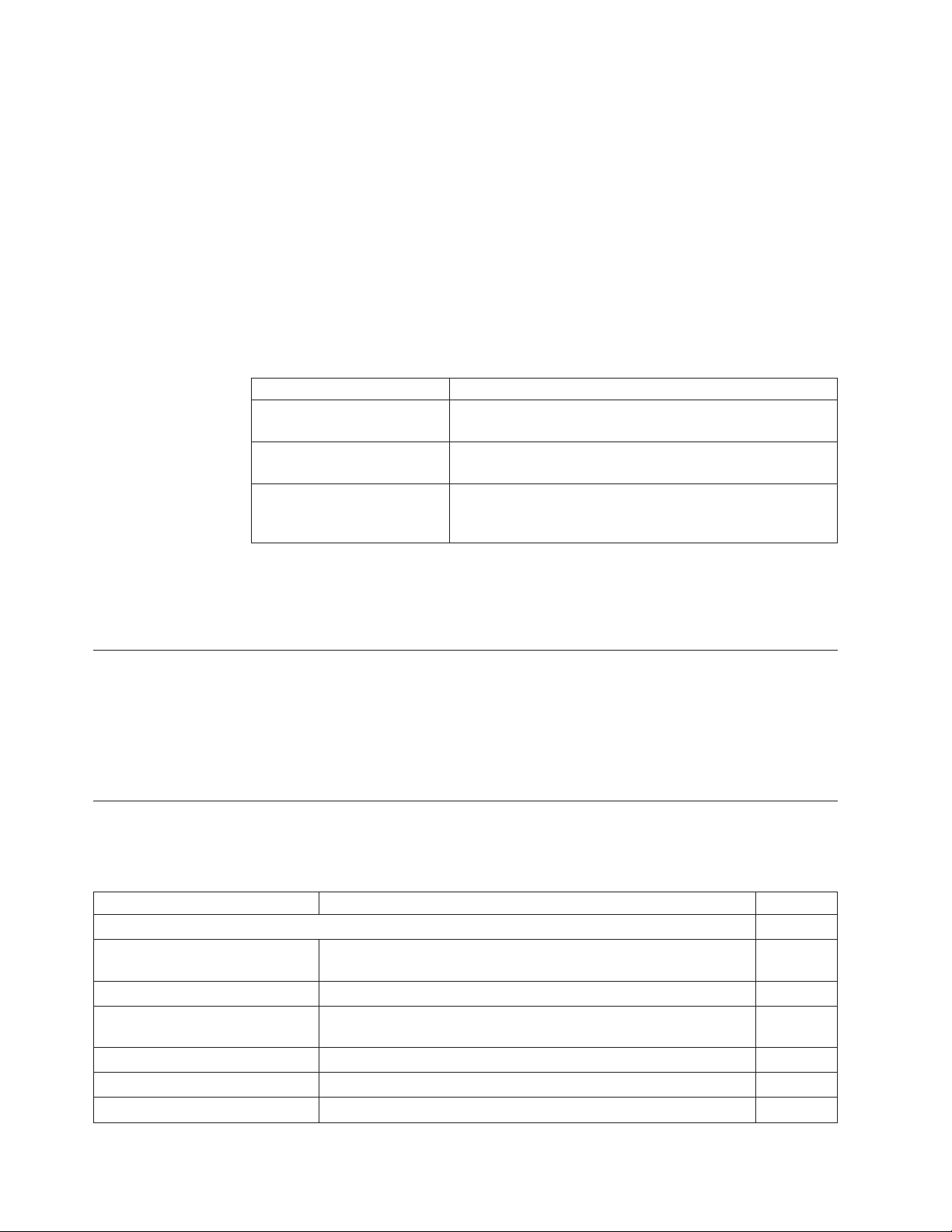
Notices in this guide are defined as follows:
Notes These notices provide important tips, guidance, or advice.
Important These notices provide information or advice that might help you
Attention These notices indicate potential damage to programs, devices, or
CAUTION These statements indicate situations that can be potentially
DANGER These statements indicate situations that can be potentially lethal
avoid inconvenient or problem situations.
data. An attention notice is placed just before the instruction or
situation in which damage could occur.
hazardous to you. A caution statement is placed just before the
description of a potentially hazardous procedure step or situation.
or extremely hazardous to you. A danger statement is placed just
before the description of a potentially lethal or extremely
hazardous procedure step or situation.
Providing feedback
Your feedback is important in helping IBM provide accurate and high-quality
information.
To provide feedback to IBM:
v Print the reader's comment form included in the back of this document.
v Complete the form, including a reference to the specific location of the text (for
example, the page or table number) in question.
v Return the completed form to IBM by mail or you can give the form to an IBM
representative.
Between major revisions of this document, there might be minor technical updates.
The latest version of this document is available on the IBM Retail Store Solutions
Website at www.ibm.com/solutions/retail/store/support/. Click Publications to
search for the most current version of this document.
xii SureMark 4610 Printers : Programming Guide for Models 1xR and 2xR
Page 15

Summary of changes
October 2011
|
|
|
|
|
June 2009
April 2009
This update provides additional changes throughout the entire book from the new
spec and the subject matter expert.
Changes or additions to the text are indicated by a change bar to the left of the
text.
This update provides additional changes throughout the entire book from the new
spec and the subject matter expert.
This update provides changes throughout the book from the new spec.
© Copyright IBM Corp. 2008, 2011 xiii
Page 16

xiv SureMark 4610 Printers : Programming Guide for Models 1xR and 2xR
Page 17
Chapter 1. Introducing the 4610 Models 1xR and 2xR
|
|
|
|
The IBM SureMark printer Models 1xR and 2xR printers consist of a high-speed
thermal station and an impact station for printing inserted documents. For further
information about the physical specifications of Models 2xR and 1xR, refer to the
User's Guide for Models 2xR and 1xR, GA27-5003-00.
Operating system requirements
Drivers can be downloaded from the Retail Store Solutions Web site at
www.ibm.com/solutions/retail/store/support/.
RS-232 interface
|
|
|
|
|
|
|
|
|
|
|
|
|
|
|||
|
|
|
|
||
|||||||
|
|||||||
||||||
|
|
|
|
|
|
||||||
|
|
|
|
||||||
|
|
|
|
||||||
|
|
|
|
||||||
|
|
|
||||||
|
|
|
|
||||||
|
|
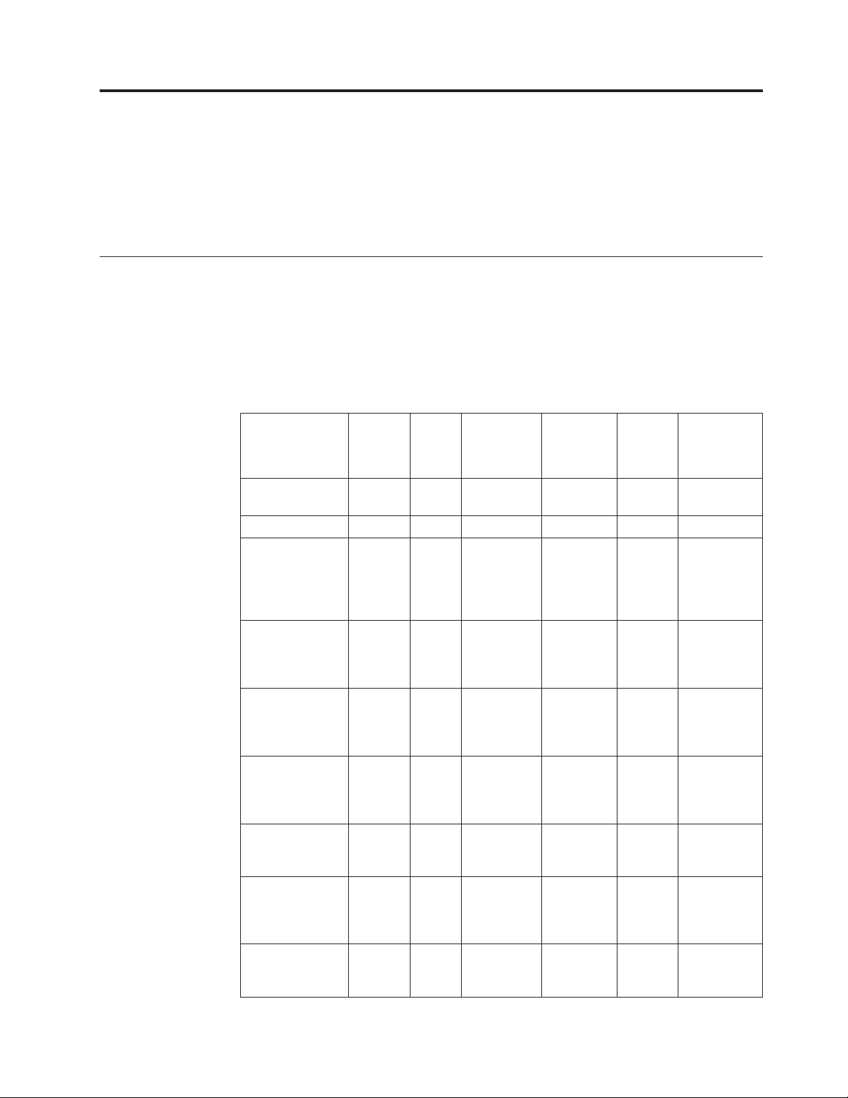
The RS-232 interface supports systems with the following operating systems:
Table 1. RS-232 operating systems supported
Operating
System
IBM 4690 Yes V5R2 and
Windows XP Yes Yes Yes Yes
Microsoft
Windows
Embedded for
Point of Service
(WEPOS) 1.11
Microsoft
Windows
Embedded
POSReady 2009
Microsoft
Windows 7
(Professional/
Ultimate)
IBM Retail
Environment for
SUSE Linux
(IRES)
Novell Linux
Point of Service
(NLPOS)
SUSE Linux
Enterprise
Desktop (SLED)
11
SUSE Linux
Enterprise Server
(SLES) 11
JavaPOS
Drivers
1.9.6 or
later
Ye s Ye s Ye s Ye s
Ye s Ye s Ye s Ye s
Ye s Ye s Ye s Ye s
Ye s Ye s
Ye s Ye s
Ye s Ye s
Ye s Ye s
OPOS
Drivers
1.9.6 or
later
POS
Subsystem
1.9.6 or later
Windows
Native
Drivers
(NWD)
Direct
IO Comments
V6R2
*
© Copyright IBM Corp. 2008, 2011 1
Page 18
|
|
|
|
|
|
|
|
|
|
|
|
|||
|
|
|
|
||
||||||
|
|
|
|
|||||||
|
|
|
|
Table 1. RS-232 operating systems supported (continued)
JavaPOS
Drivers
Operating
System
SUSE Linux
Enterprise Point
of Service
(SLEPOS) 11
PC DOS 2000 Yes
* The 2NR/2CR printers are supported in compatibility mode in V5R2, but 4690 OS can
only update the firmware starting with the 0820 maintenance package. The 1NR is
supported in compatibility mode in V5R2, but requires package 0900 for firmware update.
All of these models are supported in compatibility or native mode in V6R2.7.
1.9.6 or
later
Ye s Ye s
OPOS
Drivers
1.9.6 or
later
POS
Subsystem
1.9.6 or later
Windows
Native
Drivers
(NWD)
Direct
IO Comments
|
|
4690 OS
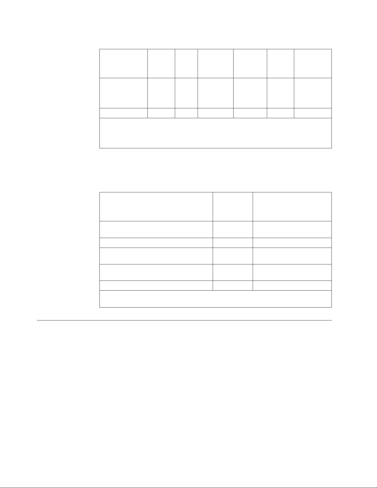
Customers must be at these application levels (or higher) when running the 4690
OS:
Application Name
Note: Some of these applications will only
support the printers if they are set in TI3/4
compatibility mode.
IBM SUREPOS Application Client/Server
Environment for 4690 OS
IBM Chain Drug Sales Application 5669-212 9701 with PRPQ 5799-QYP
IBM 4680/4690 General Sales Application 5696-546 9701 with APAR IR33229 and
IBM 4680/4690 Supermarket Application 5696-536 9701 with APAR IR33228 plus
|||
Linux See note Release 1.4
Note: 4690 Terminal Services for Windows NT is required when you use Windows NT 4.0
or Windows 2000 as the primary operating system with this 4690 application.
Hardware requirements
SureMark printers operate with the following systems:
v IBM 4694
v IBM 4695 (RS-232 connection only and with power supply)
v PC or other store controller with an RS-232 or USB port
v SurePOS 100 Series
v SurePOS 700 Series
v SurePOS 500 Series
v SurePOS 300 Series
v IBM Self Checkout
|
v IBM Anyplace Kiosk
Product
Number
5745-C44 N/A
Maintenance Level
PRPQ 5799-QYN
PRPQ 5799-QYL
2 SureMark 4610 Printers : Programming Guide for Models 1xR and 2xR
Page 19

Updating the firmware
A SureMark printer that is RS-232 attached has the capability to receive SureMark
firmware updates from its attached host system unit. To update the firmware, use
the latest drivers from the IBM Retail Store Solutions Web site:
www.ibm.com/solutions/retail/store.
Chapter 1. Introducing the 4610 Models 1xR and 2xR 3
Page 20

4 SureMark 4610 Printers : Programming Guide for Models 1xR and 2xR
Page 21

Chapter 2. Communication parameters
RS-232 serial parameter ...........6
RS-232 commands summary by function .....6
Alphabetized commands summary ......10
System commands ............13
Verify previous commands completed ....13
Status request ............13
Reset printer .............13
EC/Request/Real-time status request.....14
Retrieve Native Mode Status (when printer is in
|
compatibility mode) ..........14
||
Retrieve Native Mode Device ID (when printer is
|
in compatibility mode) .........14
||
Extended address command-request printer ID 15
Printer ID format ...........15
Emulation mode for Model 1xR / 2xR .....16
Emulation of Non-IBM printers........17
Preset or onetime-set commands .......18
Memory allocation ...........18
Double-byte characters .........20
Download graphics (logo) commands ....20
Predefine messages ...........22
Download user-defined characters ......23
Thermal code page ..........24
Proportional font ..........25
Impact code page ..........27
User-defined code page mapping ......28
Request checksum of flash memory sector . . . 29
Retrieve checksum of each downloaded logo or
each stored message ..........29
Flash storage write ...........30
Erase flash sector ...........30
Microcode tolerance (MCT) information - loading 31
Microcode tolerance (MCT) information - request 31
Setup commands ............35
Set print mode ............35
||
Set or cancel double-wide mode ......37
Set or cancel double-high mode ......37
Set or cancel underline mode .......38
Set or cancel overline mode ........38
Set or cancel invert mode .........38
Set or cancel emphasized printing ......38
Select maximum print speed........39
Set or cancel unidirectional printing .....39
Set document length for landscape print....39
Request document length for landscape print . . 40
Set print station ............40
Select user-defined or resident character sets . . 41
Set code page.............41
Set intercharacter spacing for single byte
character sets .............42
Set intercharacter spacing for double byte
character sets .............42
Set or cancel rotated characters .......43
Set print station parameters ........43
Select 1/8-inch line spacing ........43
Select 1/6-inch line spacing ........44
Select color printing ..........44
Set line spacing using minimum units ....45
Set sheet eject length ..........45
Set horizontal tab positions ........46
Set left margin position .........46
Set right margin position .........47
Set relative position...........47
Set low paper calibration .........48
Align positions ............48
Set error recovery function ........49
Define document wait time ........49
Status sent to system ..........50
Select character for reprinted lines ......50
Re-initialize the printer .........51
Enable or disable the beeper ........51
Enable or disable the feed buttons .....52
Enable or disable upside-down printing ....52
Select character size for scalable fonts ....53
Fix font matrix ............54
Print logo inline ............54
Set or cancel strike-through ........55
Select thermal paper ..........55
Bar code commands ...........56
Print bar code ............56
Print bar code examples ........61
Select horizontal size of bar code ......61
Select bar code height ..........61
Select printing position of human readable
information (HRI) ...........61
Select font for HRI ...........62
Print PDF417 bar code..........62
Select PDF417 ECC (error correction codewords)
level ................63
Select aspect ratio PDF417 bar code .....63
Enable PDF417 truncation ........64
Print character commands .........64
Print and line feed ...........64
Print and line feed ...........64
Print, form feed, and cut the paper (FF) ....64
Print and feed paper n lines ........65
Print and feed paper using minimum units . . . 65
Print graphic messages ..........65
Select and print a graphics (logo) command . . 65
Print predefined graphics (logo) command . . . 67
Enable watermark printing ........68
Print predefined messages ........68
Check processing commands - 2CR only ....69
MICR read .............69
Flip check ..............71
Miscellaneous commands..........71
Horizontal tab ............71
Backspace for composite characters .....71
Return home (select print head location)....72
Paper cut/DI eject ...........73
Generate drive pulse for cash drawer.....73
Retrieve the flash storage.........73
© Copyright IBM Corp. 2008, 2011 5
Page 22
Retrieve size of user flash storage ......74
Prepare printer for shut down (S3) .....74
||
Asynchronous (real-time) commands ......74
Real-time requests ...........74
Data buffer management and batch printing . . . 76
Unless noted otherwise, the communication parameters in this section apply to
SureMark printers that attach to a POS system with an RS-232 (EIA232) cable
connection.
If you use the RS-485 or USB communications interface, refer to either the
SureMark driver documentation in the appropriate IBM book for your operating
system (see Table 2) or, when using OPOS drivers, to the OLE for Retail POS
Application Programming Guide.
Table 2. Driver documentation by operating system
Operating System IBM Publication
4690 OS Version 1 and
Version 2
DOS IBM Point-of-Sale Subsystem for DOS Programming
OS/2, Windows NT,
Windows 95, and Windows
3.1x
Marker command ...........76
Reset line count ............77
Disable line count ...........77
Hold printing until buffer is released .....77
Release print buffer...........78
IBM 4690 OS API Specification for IBM 4610 Printers
Reference
IBM Point-of-Sale Subsystem Programming Reference and
User's Guide
The 4690 OS manual is available on the current maintenance diskette for the IBM
4690 operating system. Current versions of all publications are available on the RSS
web site.
RS-232 serial parameter
Protocol DTR/DSR mode or XON/XOFF mode
Baud Rate 9600, 19200, 115200
Start 1 bit Data 8 bits Parity None Stop 1 bit
RS-232 commands summary by function
The commands listed in Table 3 are described in detail in the following sections.
Table 3. RS-232 commands organized by function
Description Command Page
System Commands
EC/Request/Real-time status
request
Enable/disable the feed buttons ESCc5nX'1B6335;n' 52.
Extended address command
(request printer ID)
Re-initialize the printer ESC @ or X'1B40'. 51
Reset printer DLE ENQ @ or X'100540' 13
Status request ESC v or X'1B76' 13
DLE ENQ 4 or X'100534' Immediate or X'1B008000' Buffered 14
GS | SOH or X'1D4901' This is an IMMEDIATE command. 15
6 SureMark 4610 Printers : Programming Guide for Models 1xR and 2xR
Page 23
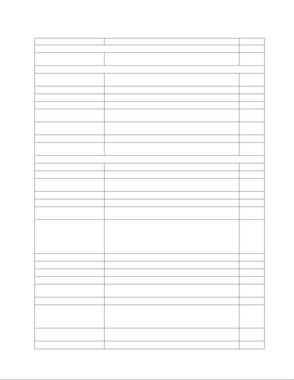
Table 3. RS-232 commands organized by function (continued)
Description Command Page
System Commands
Verify previous commands
X'1B00;80;00' 13
completed
Preset or Onetime-Set Commands
Download graphics (logo)
GS * logo# n1 n2 data or X'1D2A';logo#;n1;n2;data 20
commands
Download user-defined characters ESC & s n m data or X'1B26;s;n;m;data' 23
Erase flash EPROM sector ESC # n or X'1B23;n' 30
Flash storage write ESC ' n1 n2 data or X'1B27;n1;n2;data' 30
Microcode tolerance (MCT)
ESC M nhlor X'1B4D;n;h;l'. 31
information - loading
Microcode tolerance (MCT)
ESC S n or X'1B53;n' 31
information - request
Predefine messages GS : message# data GS : or X'1D3A; message#;data;'X'1D3A' 22
Send checksum of flash EPROM
ESC " n or X'1B22;n' 29
sector
Setup Commands
Align positions ESC a n or X'1B61;n'. 48
Define document wait time ESC f xyor X'1B66;x;y' 49
Enable/disable upside-down
ESC { n or X'1B7B;n' 52
printing
Fix font matrix ESC : n or X'1B3A n' 54
Print logo inline GS J d n1 n2 data or X'1D4A;d;n1;n2;data' 54
Request document length for
GS N X'02' Null or X'1D4E0200' 40
landscape print
Request document length for
landscape print
GSc1n where n = 2 bytes indicating the length of the document
in print motor steps.
“Request
document
length for
landscape
print” on
page 40
Select 1/8-inch line spacing ESC 1 or X'1B31'. 43
Select 1/6-inch line spacing ESC 2 or X'1B32' 44
Select color printing ESC r n or X'1B72;n' 44
Select character for reprinted lines ESC + n or X'1B2B;n' 50
Select character size for scalable
GS ! n or X'1D21;n' 53
fonts
Select maximum print speed ESC / n or X'1B2F;n' 39
Select thermal paper GS; n or X'1D 3B n' “Select
thermal
paper” on
page 55
Select user-defined or resident
ESC % n or X'1B25;n' 41
character sets
Set code page ESC t n or X'1B74;n' 41
Chapter 2. Communication parameters 7
Page 24
Table 3. RS-232 commands organized by function (continued)
Description Command Page
System Commands
Set document length for
landscape print
Set error recovery function ESC c 4 n or X'1B63;34;n' 49
Set horizontal tab positions ESC D [n1 n2] NUL NUL or X'1B44[n1 n2]0000' 46
Set intercharacter spacing ESC SP n or X'1B20;n' 42
Set left margin position ESC $ n1 n2 or X'1B24;n1;n2' 46
Set line spacing using minimum
units
Set or cancel double-wide mode ESC W n or X'1B57;n' 37
Set or cancel double-high mode ESC h n or X'1B68;n' 37
Set or cancel emphasized printing ESC G n or X'1B47;n' 38
Set or cancel invert mode ESC H n or X'1B48;n' 38
Set or cancel overline mode ESC x‘5F’ n or X'1B5F;n' 38
Set or cancel rotated character ESC V n or X'1B56;n' 43
Set or cancel underline mode ESC − n or X'1B2D;n': 38
Set or cancel unidirectional
printing
Set print mode ESC ! n or X'1B21;n' 35
Set print station ESC c 0 n or X'1B6330;n' 40
Set print station parameters ESC c 1 n or X'1B6331;n' 43.
Set relative position ESC \ n1 n2 or X'1B5C;n1;n2' 47
Set right margin position ESC ] n1 n2 or X'1B 5D;n1;n2'' “Set right
Set sheet eject length ESC C n or X'1B43;n' 45
Status sent to system ESC ) n or X'1B29;n' 50
Bar Code Commands
Enable PDF417 truncation GS T n or X'1D54;n' 64
Select Aspect Ratio PDF417 bar
code
Print bar code GS k n NUL or X'1D6B;n;data;00' 56
Print PDF417 bar code GS P data NUL or X'1D50;data;00' 62
Select bar code height GS h n or X'1D68;n' 61
Select font for HRI GS f n or X'1D66;n' 62
Select horizontal size of bar code GS w n or X'1D77;n' 61
Select printing position of
human-readable information
(HRI)
GSc1n where n = 2 bytes indicating the length of the document
in print motor steps.
ESC 3 n or X'1B33;n' 45
ESC U n or X'1B55;n' 39
GS S r;c or X'1D53;r;c' 63
GS H n or X'1D48;n' 61
“Set
document
length for
landscape
print” on
page 39
margin
position”
on page 47
8 SureMark 4610 Printers : Programming Guide for Models 1xR and 2xR
Page 25
Table 3. RS-232 commands organized by function (continued)
Description Command Page
System Commands
Select PDF417 ECC Level GS R n or X'1D52;n1;n2' 63
Print Character Commands
Print and line feed LF or X'0A' or CR or X'0D' 64
Print, form feed, and cut the
FF or X'0C' 64
paper (FF)
Print and feed paper n lines ESC d n or X'1B64;n' 65
Print and feed paper using
ESC J n X'1B4A;n' 65
minimum units
Print Graphic Messages
Select and print a graphics (logo)
ESC * d w h data or X'1B2A;d;w;h;data' 65
command
Print predefined graphics (logo)
GS / m logo# or X'1D2F;m;logo#' 67
command
Print predefined messages GS ^ message# or X'1D5E;message#' 68.
Miscellaneous Commands
Retrieve checksum of each
ESC | n1 n2 or X'1B7C n1 n2' 29
downloaded logo or each stored
message
Tab to next tab stop HT or X'09' 71
Return home (select print head
ESC <nor 1B3C;n 72
location)
Paper cut/DI eject ESC i or ESC m -- X'1B69' or X'1B6D' 73
Generate drive pulse for cash
ESC p mn1n2or X'1B70;m;n1;n2' 73.
drawer
Retrieve the flash storage ESC 4 n1 n2 X'1B34;n1;n2' 73
Retrieve size of user flash storage ESC 4 x '03 FF FF FF' or X'1B3403FFFFFF' 74
Check Processing Commands
Flip check ESC 5 or X'1B35' 71
MICR read ESC I or X'1B49' 69
Asynchronous (Real-Time) Commands
Real-time requests DLE ENQ n or X'1005n' 74
Data Buffer Management and Batch Printing
Reset line count ESC 6 or X'1B36' 77
Disable line count ESC 8 n or X'1B38'n 77
Hold printing until buffer is
ESC 7 or X'1B37' 77
released
Release print buffer DLE ENQ 1 X'10;05;31'' 78
Page Mode Printing Commands
Select page mode ESC L or X'1B4C' 79
Select standard mode ESC S or X'1B4f' 79
Select printable area ESC X or X'1B58;x;y;dx;dy' 79
Select printing direction/position ESC T n or X'1B54;n' 80
Chapter 2. Communication parameters 9
Page 26
Table 3. RS-232 commands organized by function (continued)
Description Command Page
System Commands
Set vertical position GS $ y or X'1D24;y' 80
Set relative vertical position GS \ y or X'1D5C;y' 80
Set right margin position ESC ] n1 n2 or X'1B5D;n1;n2'' 47
Set left margin position (standard
mode), Set absolute print position
(page mode)
Set relative horizontal position ESC <5C>h n1 n2 or X'1B5C;n1;n2' 81
Set printing position GS ] xyor X'1D5D;x;y' 82
Print and form feed and cut the
paper
Print page in page mode ESC FF or X'1B0C' 83
Clear print data in page mode CAN or X'18' 83
ESC $ n1 n2 or X'1B24;n1;n2' 81
FF or X'0C' 82
Alphabetized commands summary
Table 4. Commands in alphabetical order
Description Command Page
Align positions ESC a n or X'1B61;n' 48
Clear print data in page mode CAN or X'18' 83
Disable line count ESC 8 n or X'1B38'n 77
Define document wait time ESC f xyor X'1B66;x;y' 49
Download double-byte characters 485/USB Syntax: X'1B28;s;n;data' RS232 Syntax: ESC s ( n data or
X'1B;28;s;n;data''
Download graphics (logo)
commands
Download user-defined characters ESC & s n m data or X'1B26;s;n;m;data' 23
Enable PDF417 truncation GS T n or X'1D54;n' 64
Enable/disable the feed buttons ESCc5nX'1B6335;n' 52.
Enable/disable two-color printing GS; n or X'1D3B n' 55
Enable/disable upside-down
printing
Erase flash EPROM sector ESC # n or X'1B23;n' 30
Extended address
command-request printer ID
Fix font matrix ESC : n or X'1B3A;n' 54
Flash storage write ESC ' n1 n2 data or X'1B27;n1;n2;data' 30
Flip check ESC 5 or X'1B35' 71
Generate drive pulse for cash
drawer
Hold printing until buffer is
released
Impact code page MCT commands. 27
GS * logo# n1 n2 data or X'1D2A;logo#;n1;n2;data' 20
ESC { n or X'1B7B n' 52
GS | or X'1D4901' 15
ESC p mn1n2or X'1B70;m;n1;n2' 73
ESC 7 or X'1B37' 77
20
10 SureMark 4610 Printers : Programming Guide for Models 1xR and 2xR
Page 27
Table 4. Commands in alphabetical order (continued)
Description Command Page
MICR read ESC I or X'1B49' 69
Microcode tolerance (MCT)
ESC M nhlor X'1B4D;n;h;l' 31
information - loading
Microcode tolerance (MCT)
ESC S n or X'1B53;n' 31
information - request
Paper cut/DI eject ESC i or ESC m or X'1B69' or X'1B6D' 73
Predefine messages GS : message# data GS : or X'1D3A;message#;data;1D3A' 22
Print and feed paper n lines ESC d n or X'1B64;n' 65
Print and feed paper using
ESC J n or X'1B4A;n' 65
minimum units
Print and line feed LF or X'0A' 64
Print and line feed CR or X'0D' 64
Print bar code GS k n NUL or X'1D6B;n;data;00' 56
Print logo inline GS J d n1 n2 data or X'1D4A;d;n1;n2;data' 54
Print page in page mode ESC FF or X'1B0C' 83
Print PDF417 bar code GS P data NUL or X'1D;50;data;00' 62
Print predefined graphics (logo)
GS / m logo# or X'1D2F;m;logo#' 67
command
Print predefined messages GS ^ message# or X'1D5E;message#' 68
Proportional font ESC & s n m data or X'1B26;s;n;m;data' 25
Real-time requests DLE ENQ m or X'1005n' 74
Re-initialize the printer ESC @ or X'1B40' 51
Request document length for
GS N X'02' Null or X'1D4E;02;00' 40
landscape print
Reset line count ESC 6 or X'1B36' 77
Retrieve size of user flash storage ESC 4 x '03 FF FF FF' or X'1B34;03;FF;FF;FF' 74
Retrieve the flash storage ESC 4 n1 n2 X'1B34;n1;n2' 73
Retrieve checksum of each
ESC | n1 n2 or X'1B7C;n1;n2' 29
downloaded logo or each stored
message
Return home (select print head
ESC < n or X'1B3C;n' 72
location)
Select and print a graphics (logo)
ESC * d w h data or X'1B2A;d;w;h;data' 65
command
Select aspect ratio PDF417 bar code GS S r;c or X'1D53;r;c' 63
Select bar code height GS h n or X'1D68;n' 61
Select character for reprinted lines ESC + n or X'1B2B;n' 50
Select character size for scalable
GS ! n or X'1D21;n' 53
fonts
Select color printing ESC r n or X'1B72;n' 44
Select font for HRI GS f n or X'1D66;n' 62
Select horizontal size of bar code GS w n or X'1D77;n' 61
Select page mode ESC L or X'1B;4C' 79
Chapter 2. Communication parameters 11
Page 28
Table 4. Commands in alphabetical order (continued)
Description Command Page
Select PDF417 ECC level GS R n or X'1D52;n1;n2' 63
Select printable area ESC X or X'1B58;x;y;dx;dy' 79
Select printing direction/position ESC T n or X'1B54;n' 80
Select printing position of
human-readable information (HRI)
Select standard mode ESC S or X'1B4f' 79
Select user-defined or resident
character sets
Select 1/6-inch line spacing ESC 2 or X'1B32' 44
Select 1/8-inch line spacing ESC 1 or X'1B31' 43
Send checksum of flash EPROM
sector
Select maximum print speed ESC / n or X'1B2F;n' 39
Set code page ESC t n or X'1B74;n' 41
Set document length for landscape
print
Set error recovery function ESC c 4 n or X'1B63;34;n' 49
Set horizontal tab positions ESC D [n1 n2] NUL NUL or X'1B44[n1n2]0000' 46
Set intercharacter spacing ESC SP n or X'1B20;n' 42
Set left margin position ESC $ n1 n2 or X'1B24;n1;n2' 46
Set left margin position (standard
mode), Set absolute print position
(page mode)
Set line spacing using minimum
units
Set or cancel double-high mode ESC h n or X'1B68;n' 37
Set or cancel double-wide mode ESC W n or X'1B57;n' 37
Set or cancel emphasized printing ESC G n or X'1B47;n' 38
Set or cancel invert mode ESC H n or X'1B48;n' 38
Set or cancel overline mode ESC x‘5F’ n or X'1B5F;n' 38
Set or cancel rotated character ESC V n or X'1B56;n' 43
Set or cancel underline mode ESC − n or X'1B2D;n' 38
Set or cancel unidirectional
printing
Set print mode ESC ! n or X'1B21;n' 35
Set print station parameters ESC c 1 n or X'1B63;31;n' 43
Set print station ESC c 0 n or X'1B63;30;n' 40
Set printing position GS ] xyor X'1D5D;x;y' 82
Set relative horizontal position ESC <5C>h n1 n2 or X'1B5C;n1;n2' 81
Set relative position ESC \ n1 n2 or X'1B5C;n1;n2' 47
Set right margin position ESC ] n1 n2 or X'1B5D;n1;n2'' 47
Set low paper calibration GSc2orX'1D63;32' 48
GS H n or X'1D48;n' 61
ESC % n or X'1B25;n' 41
ESC " n or X'1B22;n' 29
GSc1n 39
ESC $ n1 n2 or X'1B24;n1;n2' 81
ESC 3 n or X'1B33;n' 45
ESC U n or X'1B55;n' 39
12 SureMark 4610 Printers : Programming Guide for Models 1xR and 2xR
Page 29
Table 4. Commands in alphabetical order (continued)
Description Command Page
Set relative vertical position GS \ y or X'1D5C;y' 80
Set sheet eject length ESC C n or X'1B43;n' 45
Set vertical position GS $ y or X'1D24;y' 80
Status request ESC v or X'1B76' 13
Status sent to system ESC ) n or X'1B29;n' 50
Tab to next tab stop HT or X'09' 71
Thermal code page MCT commands; see Table 8 on page 31. 24
Verify previous commands completed
X'1B00;80;00' 13
System commands
This section describes the system commands.
Verify previous commands completed
Syntax:
X'1B00;80;00'
Purpose:
This command is used to ensure that all commands preceding it have been
completed. The application waits for the status return with status byte 5,
bit 1 set.
Remarks:
The printer status is returned in status bytes 1–16. Status byte 5, bit 1 is set
after this request has been executed. See Chapter 5, “Status information,”
on page 89 for more information.
Error Conditions:
None
Status request
Syntax:
ESC v or X'1B76'
Purpose:
The printer status is sent to the system. This command will be processed in
the order it was received.
Remarks:
The printer status is returned in status bytes 1–16. See Chapter 5, “Status
information,” on page 89 for more information. For RS-232 printers, this
command is always buffered and processed in the order it is received.
Error Conditions:
Reset printer
Syntax:
None
DLE ENQ @ or X'100540'
Chapter 2. Communication parameters 13
Page 30

Purpose:
The printer stops if processing a command and begins its reset routine. The
print buffer is canceled. All commands are erased. All printer settings go
back to default values.
Remarks:
None
Error Conditions:
None
EC/Request/Real-time status request
Syntax:
DLE ENQ 4 or X'100534' Immediate or X'1B008000' Buffered
Purpose:
To send the printer status to the system.
Remarks:
The printer status is returned in status bytes 1–16. Status byte 5 bit is set
after the EC request is executed. When used as a buffered command, this
command can be used to insure that all commands preceding it have been
completed. The application waits for the status to return with Status Bytes
5, bit 1 set. (See Chapter 5, “Status information,” on page 89.)
Error conditions:
None
|
|
|
|
|
|
|
|
|
|
|
|
|
|
|
|
|
|
Retrieve Native Mode Status (when printer is in compatibility mode)
Syntax:
GS N ENG NULL or X'1D;4E;05;00'
Purpose:
To read the native mode status when in compatibility mode.
Remarks:
16 status bytes of data will be sent over the serial following the status
bytes. Status byte 5 is set, indicating that there is extra data attached.
Note: Supported on 2xR/1NR printers.
Error conditions:
None
Retrieve Native Mode Device ID (when printer is in compatibility mode)
Syntax:
GS N ENG NULL or X'1D;4E;05;01'
Purpose:
To read out the native mode device ID when in compatibility mode.
|
|
|
|
Remarks:
Following the 8 compatibility mode status bytes is the native mode device
ID status bytes.
Note: Supported on 2xR/1NR printers.
14 SureMark 4610 Printers : Programming Guide for Models 1xR and 2xR
Page 31

|
|
Error conditions:
None
Extended address command-request printer ID
Syntax:
GS | SOH or X'1D4901'
Purpose:
This command returns 15 bytes of printer-specific information following
the printer status.
Printer ID format
Table 5. Device Type = 30
Byte 1: Device type = 30 Reserved
Byte 2: Device ID
Byte 3: EC – HW version level Reserved
Byte 4: EC – Software release level This level increments after a formal test cycle
Byte 5: EC – Software interim version Level The level that would increment as fixes were
Byte 6: CR station width
Byte 7: DI station width
2CR/2NR = 0x50
1NR = 0x00
Byte 8: Feature byte detection
2CR / 2NR / 1NR = 0xFF
08
on the code. (This is the same as Status byte
#4)
released for test. If a customer had a
“pre-released” level, this would be used to
track their level.
v 72 (0x48): 72 mm print width for 80 mm
paper width
v 50 (0x32): 50 mm print width for 58 mm
paper width
Portrait station width 80 or 0x50 for 80 mm
print width
Note: The 4610 is 80.33 mm print width; 474
dots at 150 dpi, and 374 at 120 dpi
Bit 0 Two-color printing
Bit 1 Two-color enabled
Bit 2 CR Cutter
Bit 3 Out of Paper detection
Bit 4 Low Paper Detection
Bit 5 Cover Open Detection
Bit 6 Paper jam detection
Bit 7 Cutter failure
Chapter 2. Communication parameters 15
Page 32

Table 5. Device Type = 30 (continued)
Byte 9: Feature byte
2CR = 0x9E
2NR = 0x86
1NR = 0x80
Bit 0 Reserved
Bit 1 DI Landscape Station; N/A for
Model 1xR
Bit 2 DI Station support multipart forms;
N/A for Model 1xR
Bit 3 MICR reader present; N/A for
Models 2NR and 1xR
Bit 4 Flipper present; N/A for Models
2NR and 1xR
Bit 5 Scanner present; N/A for Models
1xR and 2xR
Bit 6 Journal print station – N/A for
Models 1xR and 2xR
Bit 7 Cash drawer capable. Cannot detect
when cash drawer is attached.
Byte 10: Feature byte
Byte 11: Feature byte Command set version. This is incremented
Byte 12: Feature byte Reserved
Byte 13: Feature byte Reserved
Byte 14: Feature byte Reserved
Byte 15: Feature byte Reserved
Bit 0 DBCS capable
Bit 1 DBCS enabled (character sets
downloaded and DBCS mode
selected)
Bit 2 EJ capable
Bit 3 EJ enabled (memory allocated for EJ)
Bit 4 Beeper present - N/A for 2CR and
2NR
Bit 5 Reserved
Bit 6 Reserved
Bit 7 Reserved
when major printer functions change.
Emulation mode for Model 1xR / 2xR
The emulation mode for Model 1xR/2xR is intended for customers with
applications that are hard-coded for their existing SureMark printers.
When in emulation mode, the printer will:
v Respond to the Device ID command and match one of the existing printers.
v Return a status that:
– Matches the existing printers of 8 status bytes.
– Fixes the “Status Byte 4” (for RS-232) EC level at 0x61
16 SureMark 4610 Printers : Programming Guide for Models 1xR and 2xR
Page 33

– Fixes the EC level in the DEVICE ID at 0x61.
– Sets status byte 1 bit 6 (CR cover open) if any of the following errors are
detected:
- CR feed error (status byte 11 bit 0)
- CR paper out (status byte 8, bit 5)
- Cutter jam (status byte 11 bit 5)
v Firmware download and erase commands: The firmware will look at the code
that is downloaded to verify that the code is 1xR/2xR code before it erases the
current code in the printer. If the code is not 1xR/2xR code, the old firmware
will not be erased. No error bit will be set.
All DBCS characters must be downloaded at the same time.
Usage variables for system management cannot be read with the same commands
as legacy printers. Use the IBM drivers for access to system management.
Physical differences between Models 1xR and 2xR and previous printers:
v The position of the cutter is different.
v Not as much paper needs to be fed to advance the paper above the print head.
v The default for the “0C” command will be less.
The diagnostic package recognizes the printer as being in emulation mode and
sends the correct firmware file to the printer for updating.
The printer will be setup in Emulation mode when sent from the factory. Any driver and
application that support Models 2xR and 1xR should put the printer into native
mode when it is installed. This can also be done using an offline setup procedure.
Emulation of Non-IBM printers
A 1xR printer can be put into EPSON Emulation mode via an Offline setup or via
a Software command, MCT #1E, bit 0. See Microcode Tolerance Information
-Loading. If the printer is in Epson Emulation mode and you want to run the IBM
Diagnostics for POS Systems and Peripherals package against the printer, then you
must put the printer into native mode or legacy mode using the printer offline test
mode before the diagnostics package is started. Once you have finished running
Diagnostics against the printer, you can set the printer back into Epson Emulation
mode using the utilities in the diagnostics package or the same function in the
printer offline test mode.
v Emulation is only supported in single-byte character set (SBCS) mode can
emulate an Epson single-station SBCS printer.
v Emulation mode provides full support for most Epson commands. However,
some commands are supported partially and a few commands are not supported
at all.
v There will be some differences in the printed output, because of different dot
pitches in the print heads and the minimum distance that the paper feed motors
can move the paper. These differences will appear when there are a number of
printed lines, and the method of aligning the data is different.
v Logos and downloadable characters are supported in emulation mode. However,
because the Epson printer prints at 180 dpi and the SureMark prints at 200 dpi,
the emulated printout will be smaller.
Chapter 2. Communication parameters 17
Page 34

v In order to implement fixes, new functionality, and other improvements, new
releases of printer microcode are routinely published. It is advisable that you run
the most recent version firmware on the printer.
v If one line is aligned using spaces and another line is aligned using the relative
position commands, the data might appear misaligned. The commands, such as
the relative position and margin commands that use the minimum unit of
motion values are based on a fraction of an inch, which eliminates the
differences in the dot pitch. Tabs and spaces are subject to pitch differences.
|
|
|
v To use one of the 1NR code pages while in EPSON Emulation Mode, store the
code page number to MCT #0x81. See “Set code page” on page 41 for additonal
information.
Preset or onetime-set commands
The SureMark printer has commands to specialize and tune each printer to
improve its usability, performance, and uniqueness. This flexibility is provided
through the use of flash erasable programmable read-only memory (flash EPROM).
Data in this memory device remains valid until it is redefined. This information
only needs to be defined once because it remains for the life of the printer or until
it is redefined.
To verify that data was previously stored in the printer, the system can request a
checksum on data stored in each sector.
The Flash EPROM can be allocated up to 10 sectors. To rewrite information in a
sector, you must first erase the sector.
v For logo commands and predefined messages, erasing the sector is necessary
only to replace a logo or predefined message number, or when the length of the
logo or message exceeds space available in that sector.
v For user flash memory, erasing the sector is necessary only when writing to an
address that has already been written to.
v For user-defined thermal and impact characters, new characters can be added if
they have the same matrix as characters already in the character set. If new
character sets are added, the flash memory does not have to be erased. To
replace characters, you must first erase the sector.
Sector Function:
1 Download graphics (logo) commands
2 Predefined messages
3 Two user-defined impact character sets
4 User-defined thermal character set: four fixed matrix or 2 proportional
5 User flash memory
7 Thermal DBCS character storage
8 Impact DBCS character storage
9 Electronic journal storage
10 User-defined code page mapping
Memory allocation
The amount of memory allocated to each function is specified by the value stored
to its respective MCT location. (See Microcode Tolerance Information - Loading
18 SureMark 4610 Printers : Programming Guide for Models 1xR and 2xR
Page 35

and Microcode Tolerance Information - Request commands regarding information
for adjusting these values.) The MCT value represents the number of 64KB sectors
assigned to the respective function.
In Model 2xR/1xR reallocation: To change the memory allocation of any of the
character sets (user-defined impact characters, user-defined thermal characters,
thermal DBCS character storage, Impact DBCS character storage), ALL memory
partitions must be emptied or erased. To change the memory allocation of any of
the remaining functions, ALL remaining memory partitions must be
emptied/erased. If the memory is not erased, an MCT write error status will be
returned.
After the MCT values are written, the new values will not take effect until after a
reset. The new memory allocations will start with the user defined character sets
(sectors 3 and 4), and then the DBCS (sectors 7 and 8), and then increment upward
starting with sector 1. Memory will be allocated until all requests are satisfied, or
until all available memory is used.
There is a total of forty-eight 64 KB sectors, for a total of 3.0 MB of FLASH
memory to allocate.
Note: The flash EPROM is guaranteed for a minimum life of 100,000 write/erase
commands by the flash manufacturer.
Table 6 lists the printer defaults.
Table 6. Printer memory allocation defaults
Function Default memory allocation MCT location
User-defined impact
characters**
User-defined thermal
characters
Logos 64 KB (0x0001) 0xa2
Predefined messages 64 KB (0x000a) 0xa3
User memory 128 KB (0x0002) 0xa4
Scan image storage 0 KB (0x0000) for Model 2xR
||||
Thermal DBCS character
storage
Impact DBCS character
storage**
Electronic journal storage
Note: For electronic journal
storage in the printer, use the
drivers provided by IBM. See
www.ibm.com/solutions/
retail/store.
User defined code page
mapping
**For single station printers, the impact DBCS character storage and the user-defined
impact characters storage cannot be addressed: they remain at 0 KB.
64 KB (0x0001) - 2xR
0KB-1xR
64 KB (0x0001) 0xa1
and 1xR
1152K (0x0012) 0xa6
567 KB (0x0009) 0xa7
0KB (0x0000) 0xa8
64 KB 0xa9
0xa0
0xa5
Chapter 2. Communication parameters 19
Page 36
Table 6. Printer memory allocation defaults (continued)
Function Default memory allocation MCT location
DBCS Code page
Note: As double byte code
pages are modified, these
allocations could change. See
the double-byte information
available on the RSS web
site: www.ibm.com/
solutions/retail/store
Japan - 932 0x0007 (448 KB) 0x00004 (256 KB)
Traditional Chinese - 950 0x000E (960 KB) 0x0007 (448 KB)
|||
|||
Simplified Chinese - 1381 0x0007 (448 KB) 0x0004 (256 KB)
Korean - 949 0x0007 (448 KB) 0x0003 (192 KB)
Memory allocation required
for thermal DBCS (0xa6)
Memory allocation required
for impact DBCS (0xa7)**
N/A for 1xR
In the 1xR this value is fix to
0KB.
Double-byte characters
Important
Use the IBM-provided drivers, diagnostics, and utilities to download the
DBCS characters to the printer.
Download graphics (logo) commands
Syntax:
GS * logo# n1 n2 data or X'1D2A;logo#;n1;n2;data'
Where:
logo# The logo number being stored
1 <=logo#<=255
n1 One-eighth the number of dots in the horizontal direction (width =
8 × n1).
range=1to72forathermal logo
range=1to59foranimpact logo
n2 One-eighth the number of dots in the vertical direction (height = 8
× n2).
range=1to255forathermal logo
range=1to5foranimpact logo
data The data to form the graphics image. The number of data bytes for
the image is n1×n2×8
Purpose:
To store all-points-addressable print messages
Remarks:
A checksum is stored in the printer for each logo downloaded to the
printer. See “Retrieve checksum of each downloaded logo or each stored
message” on page 29. The checksum can be read by the application to
20 SureMark 4610 Printers : Programming Guide for Models 1xR and 2xR
Page 37

determine the logos that have been stored in the printer. These messages
can be positioned on the page using the commands for setting positions.
Decimal values are shown, but all parameter values (logo number, n1, n2)
must be hex values when sent to the printer.
The dot density of these messages is specified when the message is
printed. See “Print predefined graphics (logo) command” on page 67.
The total number of data bytes defined for all defined graphics messages
depends upon the amount of memory the user has allocated. See “Memory
allocation” on page 18.
If the parameters logo#, n1, or n2 are out of range, the command is
discarded and its remaining data is processed as print data.
This command should be sent only when the data buffer is empty. See the
description of bit 6 in “Erase flash sector” on page 30.
Images for the thermal logo commands will be defined by one-dot-high
rows (horizontal slices), and the impact will be defined by eight-dot-high
rows (vertical slices).
Note: For a thermal graphic message that is 24 dots high, across the page (n1 = 72,
n2 = 3) takes over 2000 bytes of data.
Example: n1=2&n2=2
For Thermal Graphics - Defined as:
X'1D2A010202AAAAAAAAAAAAAAAAAAAAAAAAAAAAAAAA
55555555555555555555555555555555'
For Impact Graphics - Defined as:
X'1D2A020202FF00FF00FF00FF00FF00FF00FF00FF00
00FF00FF00FF00FF00FF00FF00FF00FF'
Error Conditions:
The error is status byte 3, bit 3: Flash EPROM load error. The following
conditions caused this error to occur:
Chapter 2. Communication parameters 21
Page 38

v The command is trying to redefine a logo that was already defined, or
v The allocated memory is full.
Verify the sector was erased before downloading images.
Predefine messages
Syntax:
GS : message# data GS : or X'1D3A;message#;data;1D3A'
Where:
message# The message number being stored
data All data and commands to be included in this message. No
Purpose:
To store predefined messages. This cuts transmission time. This is where
you can store the header and the trailer of receipts, for example.
Remarks:
v After a "GS :" occurs, all incoming commands are stored in the message
until another "GS :" occurs.
v “Print predefined graphics (logo) command” on page 67 can be included
in this command.
v A Checksum for each downloaded message is stored along with the
message. This can be used to verify the correct messages are stored in
the printer at printer initialization. See “Retrieve checksum of each
downloaded logo or each stored message” on page 29.
1to255
immediate commands can be included in the data.
Example:
Store a trailer message:
X'1D3A01'
'Thank You For Shopping' X'0D'
' At RSD STORE' X'0D'
'Store #1234567' X'0D'
X'1D3A'
This would store this message as predefined message 1. See “Print
predefined messages” on page 68 for printing this trailer message.
Commands for selecting the print station and print characteristics must be
included with the stored message.
Limitations:
v “Print predefined graphics (logo) command” on page 67 can be included
in this command. Select and print a graphics command cannot be used.
See “Print graphic messages” on page 65.
v “Print predefined messages” on page 68 can be included in this
command, but can only be nested one message deep.
Example: Store a predefined message ('Jane Doe') at location 3, then
issue the following commands:
1. X'1D3A06'
2. 'Welcome to Our Store' X'0D'
22 SureMark 4610 Printers : Programming Guide for Models 1xR and 2xR
Page 39

3. X'1D5E03' (This prints the message that has been stored at location 3.
The message cannot have a X'1D5Exx' in it, because that would be
more than one level of nesting.)
4. 'Is Your Cashier Today' X'0D'
5. X'1D3A'
Using the stored message and the above commands, the resulting text
will be:
Welcome to Our Store
Jane Doe Is Your Cashier Today
v These commands cannot be included in the predefined message:
– “Define document wait time” on page 49.
– “Select character for reprinted lines” on page 50.
– “Set sheet eject length” on page 45.
– “Select and print a graphics (logo) command” on page 65.
v This command should be sent only when the data buffer is empty. See
the description of bit 6 in “Erase flash sector” on page 30.
Error Conditions:
The error is Status byte 3, bit 3: Flash EPROM load error. The following
conditions caused this error to occur:
v The command is trying to redefine a logo that was already defined, or
v The allocated memory is full.
Verify that the sector was erased before downloading images.
Download user-defined characters
Syntax:
ESC & s n m data or X'1B26;s;n;m;data'
Where:
s The character set being defined
1 User-defined thermal code page 1
2 User-defined thermal code page 2
3 User-defined thermal code page 3
4 User-defined thermal code page 4
5 User-defined impact code page 1
6 User-defined impact code page 2
n The beginning ASCII address of the characters being defined.
m The ending ASCII address of the characters being defined.
data The slice data for the defined characters. Note the number of bytes
is determined by which code page is being defined and the
character matrix of that code page.
Purpose:
To define a matrix pattern for user-definable code pages stored in flash
EPROM.
Remarks:
v After characters are downloaded to the printer, they remain valid until
you redefine them. This is true even if power to the printer is removed.
Chapter 2. Communication parameters 23
Page 40

v Before the characters are defined, the sector of the flash EPROM which
stores this data must be erased. (See “Erase flash sector” on page 30.)
Also, the character matrix for the code page must have already been
defined. (See Table 8 on page 31, MCT# 3, 4, and 5.)
v Flash EPROM sector 4 contains all user-defined code pages for the
thermal print head. To redefine a code page, you must erase and
reprogram all of them.
v Flash EPROM sector 3 contains both user-defined code pages for the
impact print head. To redefine a code page, you must erase and
reprogram both of them.
v You cannot redefine one character only. You must redefine a whole code
page.
v This command should be sent only when the data buffer is empty. See
the description of bit 6 in “Erase flash sector” on page 30.
v ASCII characters 0-31 are reserved for commands.
Thermal code page
You define the character matrix (width/height) for each code page. The values are
stored as Microcode Tolerance values in the EEPROM. See Table 8 on page 31.
Note: The height must be an even number. If an odd number is downloaded, the
command will be rejected.
The number of data bytes per character loaded is 2 × the character height. The total
number of data bytes for this command is 2 × the character height × (1+m−n).
Example: 10 wide × 20 high
Defined as:
|
|
|
X'C0C0C0C0C0C0C0C0C0C0C0C0C0C0C0C0FFC0FFC0
|C0C0C0C0C0C0C0C0C0C0C0C0C0C0C0C0C0C0'
The above statement defines character X'48' as an 'H'.
24 SureMark 4610 Printers : Programming Guide for Models 1xR and 2xR
Page 41

|
Note: The number of data bytes=2×dotheight (20) = 40 bytes.
Proportional font
Note: The syntax for the proportional font command is the same command as the
“Download user-defined characters” on page 23 with limitations.
EIA-232 Syntax:
ESC & s n m data or X'1B26;s;n;m;data'
Where:
s The character set being defined
1 User-defined thermal code page 1
3 User-defined thermal code page 3
n The beginning ASCII address of the characters being defined
m The ending ASCII address of the characters being defined
data The height and width of the character, and the matrix pattern for
the data. The number of data bytes is (m−n+1) × (2+wb×32). wb is
defined in the MCT command.
Purpose:
To download and print proportional fonts (True Type fonts) in the thermal
station. Each character in the code page has its own unique width and
height. The matrix must be within the following ranges:
Remarks:
Width 8 ≤ width ≤ 32
Height
8 ≤ width ≤ 32
v Proportional and standard fonts may be used on the same line. If both
types of fonts are used on a line, you would probably use proportional
fonts for the description and resident fonts for the amounts.
v For alignment, a command that will allow right and left alignment on
the same line may be used. This will allow the user to align a column
(decimal point) on the right, and still be left-aligned. (See “Align
positions” on page 48).
v Once characters are downloaded to the printer, they remain valid until
you redefine them. This is true even if power to the printer is removed.
v Before the characters are defined, the sector of the flash EPROM which
stores this data must be erased. (See “Erase flash sector” on page 30).
v You cannot redefine one character only. You must redefine a whole code
page.
v If the parameter s, n,orm is out of range, the command is discarded
and the remaining data is processed as print data.
v This command should be sent only when the data buffer is empty. See
the description of bit 6 in “Erase flash sector” on page 30.
v ASCII characters 0 through 31 are reserved for EIA-232 functions and
cannot be defined.
v See “Proportional fonts” on page 97 for suggestions about how to
implement proportional fonts.
Chapter 2. Communication parameters 25
Page 42

Limitations:
The memory required for proportional fonts is much greater than the
memory that was required for user-defined fonts. Therefore, when code
page 1 (or 3) is set up as proportional, code page 2 (or 4) is not valid.
You cannot set up code page 2 or code page 4 as a proportional font.
A conversion program for TrueType (TT) fonts is available on the 4610 Web site.
This program converts the TT fonts to the required download format for the 4610
printers.
To download the font:
1. Store the code page matrix as an MCT value. Use the command X'1B
4D x 55 wb' where:
x X'02' for thermal code page 1, X'17' for thermal code page 3
wb The number of bytes, which is also 1⁄8 the number of dots, in
the width of the widest character. The valid range is 2≤wb≤4.
2. Erase the existing character set using the command X'1B 23 04'.
3. Use the proportional font command to download the font.
Example:
To define an A to code page 1 when wb is set to 02, enter the following:
X'1B260141410C16'
X'0F001F803FC070E06060C030C030C030C030C030C030'
X'C030FFF0FFF0C030C030C030C030C030C030C030'
X'C030000000000000000000000000000000000000000000'
This command specifies a character width of 12 dots (X'0C') and a
character height of 22 dots (X'16'). Following the width and height are 64
bytes that define the character. If, as in this case, the character is defined
before all 64 bytes have been used, the rest of the bytes are filled with X'0'
(see Figure 1 on page 27).
Note: If wb were set to 03, then the total number of data bytes would be
98 (3×32+2)
26 SureMark 4610 Printers : Programming Guide for Models 1xR and 2xR
Page 43

0000111100000000
0001111110000000
0011111111000000
0111000011100000
0110000001100000
1100000000110000
1100000000110000
1100000000110000
1100000000110000
1100000000110000
1100000000110000
1100000000110000
1111111111110000
1111111111110000
1100000000110000
1100000000110000
1100000000110000
1100000000110000
1100000000110000
1100000000110000
1100000000110000
1100000000110000
0000000000000000
0000000000000000
0000000000000000
0000000000000000
0000000000000000
0000000000000000
0000000000000000
0000000000000000
0000000000000000
0F00
1F80
3FC0
70E0
6060
C030
C030
C030
C030
C030
C030
C030
FFF0
FFF0
C030
C030
C030
C030
C030
C030
C030
C030
0000
0000
0000
0000
0000
0000
0000
0000
0000
row #
1
2
3
4
5
6
7
8
9
10
11
12
13
14
15
16
17
18
19
20
21
22
23
24
25
26
27
28
29
30
31
0000000000000000
Figure 1. Proportional font example
0000
32
Impact code page
You define the character matrix for each code page with MCT #4 for impact code
page 1 and MCT #5 for impact code page 2. See Table 8 on page 31.
If the matrix defines the characters as 9 dots high or less, a print line will be
printed in one pass of the print head. When the matrix is defined as greater than 9
dots high, it takes two passes of the print head per print line.
Landscape printing is limited to characters with a height of 9 dots or less. If
user-defined characters are to be used in landscape print mode, they must be less
than 10 dots high.
The number of data bytes per character loaded is 2 × character width. The total
number of data bytes for this command is 2 × character width × (1+m−n). Each slice
is defined with two bytes; the most significant bit (MSB) of each slice is the bottom
of the character.
When defining wire patterns, the same wire does not fire in consecutive, primary
(P) and secondary (S) positions. (The printer does not check for errors in defining
the character.) If the character is defined with dots in consecutive positions only
one of the dots is fired.)
Chapter 2. Communication parameters 27
Page 44

Example: 11 half-dots wide (or 5.5 full dots) × 9 high
Defined as:
|
X'1B26034141F000080014000200110000081100020014000800F000'
|
|
The above statement defines character X'41' as an ‘A’.
Note: The number of data bytes=2×dotwidth (11) = 22 bytes.
Error Conditions:
Flash EPROM load error - Verify the sector was erased before downloading
images.
User-defined code page mapping
485/USB Syntax:
X'1B;6a;data'
RS232 Syntax:
ESC j data or X'1B;6a;data'
Where:
data 256 bytes of data to fill code page.
Remarks:
Each character is referenced by it’s Unicode number. If the Unicode for a
character downloaded is NOT part of the resident characters stored in the
printer, a space character will be inserted.
Note: The table below only shows a portion of code page 858. If the entire
code page 858 were shown, the table would have 128 rows instead
of the 9 rows shown below.
Table 7. Unicode positions for code page 858 - 2 bytes for each mapping location
U00000C7 Ã 80h
U00000FC ³ 81h
U00000E9 é 82h
U00000E2 â 83h
................. ................. .................
U00000B9 ¹ FBh
U00000B3 ³ FCh
U00000B2 ² FDh
28 SureMark 4610 Printers : Programming Guide for Models 1xR and 2xR
Page 45

Table 7. Unicode positions for code page 858 - 2 bytes for each mapping
location (continued)
U00025A0 " FEh
For the Unicode characters supported in the printers please see separate
Spread Sheet.
Characters 0x20 through 0x7F are the same as other codepages. Therefore,
the amount of Unicode values will be from 0x80 through 0xFF ( 128
Unicode values, 256 bytes).
Selection of the User Defined code page is ignored if the code page has not
been defined. The previous codepage will still be selected.
Error conditions:
Flash EPROM Load Error - verify that this sector was erased before down
loading the images. Command Reject - when there is no memory allocated
for this function.
Request checksum of flash memory sector
Syntax:
ESC"norX'1B22;n'
Where:
n
01 Sector 1 - downloaded graphics
02 Sector2-predefined messages
03 Sector 3 - user-defined impact character set
04 Sector 4 - user-defined thermal character sets
05 Sector 5 - user flash storage
06 Thermal double byte character sets
07 Impact double byte character sets
08 User defined code page mapping
Purpose:
To verify data integrity of the data loaded in the Flash EPROM in the
printer.
Retrieve checksum of each downloaded logo or each stored message
ESC | n1 n2 or X'1B7C;n1;n2'
where
n1 = 0x01 for downloaded logos
= 0x02 for stored messages
n2 The number of the downloaded logo or message that is being
queried.
1 <n2<255 or 0x1 < n2 <= 0xFF
Purpose
To verify data integrity of the logos or messages stored in the
printer. The printer responds with a 2 byte checksum following the
status bytes. If the logo or message is not defined, the checksum
will respond as 0x0000.
Status byte 10 bit 2 will be set when this status is returned.
Chapter 2. Communication parameters 29
Page 46

Flash storage write
Syntax:
ESC ' n1 n2 data or X'1B27;n1;n2;data'
Where:
n1 = number of data bytes to store
n2 = 3-byte address where data bytes are to be stored
Error Conditions:
Flash EPROM load error - Verify the sector was erased before downloading
data.
Remarks:
The valid address range depends on the memory allocated to this function.
Use “Retrieve size of user flash storage” on page 74 to determine the valid
range.
The command is rejected when the address is out of range.
Erase flash sector
Syntax:
ESC # n or X'1B23;n'
Where:
n
Purpose:
Remarks:
01 downloaded graphics
02 predefined messages
03 user-defined impact character set
04 user-defined thermal character sets
05 flash storage
06 double byte characters
07 reserved
08 Scanned image storage area; n/a for Models 2xR and 1xR
09 Electronic journal storage area
0A User-defined code page mapping
0B-FF
Reserved
To erase the flash EPROM before downloading the data into the printer.
The command should only be sent to the printer when the buffer is empty
(status byte 2, bit 6). No other commands should be sent until this
command is complete.
Status byte 3, bit 7 (command complete bit) is set to show erasing is
finished and the command is complete.
The flash EPROM is guaranteed for a minimum life of 100,000 write/erase
commands by the Flash manufacturer.
30 SureMark 4610 Printers : Programming Guide for Models 1xR and 2xR
Page 47

Microcode tolerance (MCT) information - loading
Syntax:
ESC M nhlor X'1B4D;n;h;l'
Where:
n Microcode tolerance (MCT) that is being adjusted
h The high-order byte of MCT data
l The low-order byte of MCT data
Purpose:
The microcode tolerance (MCT) information is used to make adjustments
to the printer's microcode. MCT data is nonvolatile data stored in the
printer EPROM that is specific to a printer. For example, an MCT
parameter can be defined to adjust for mechanical tolerances which cause a
print line to not be centered on a document. Another would be for
adjusting for the number of motor steps to the first print position on a
document. This data remains intact until changed by the user.
Remarks:
Table 8 lists the MCT values by the parameter (n). The table includes the
default, the minimum, and the maximum values of each MCT.
If you try to set an MCT value out of its defined range, it is set to the
closest limit (the minimum or maximum value) or rejected.
Error Conditions:
EPROM load error
Microcode tolerance (MCT) information - request
Syntax:
ESC S n or X'1B53;n'
Where:
n Microcode tolerance (MCT) information that is being requested
Purpose:
To enable reading MCT information from EEPROM.
Remarks:
v MCT data is sent over the serial line after status bytes. See Table 8 for
the values of parameter n.
v MCT write command values that are out of range will cause the
command to be rejected. (See bit 7 of “Status byte 1” on page 90.)
Table 8. MCT command definitions
DEC HEX MCT Default Min Max
1 1 DBCS code page
Byte 1: Code page selected
Byte 2: Matrix for the
impact code page.
0 = 16 x 16 matrix
1=9x16matrix
X'FF00' X'0000' X'FFFFH'
Chapter 2. Communication parameters 31
Page 48

Table 8. MCT command definitions (continued)
DEC HEX MCT Default Min Max
2 2 Matrix of user-defined thermal code
page 1
Byte 1: Dot row width
Byte 2: Dot row height
3 3 Matrix of user-defined thermal code
page 2
Byte 1: Dot row width
Byte 2: Dot row height
4 4 Matrix of user-defined impact code page
1
Byte 1: Half-dot row width
Byte 2: Dot row height
5 5 Matrix of user-defined impact code page
2
Byte 1: Half-dot row width
Byte 2: Dot row height
23 17 Matrix of user-defined thermal code
page 3
Byte 1: Dot row width
Byte 2: Dot row height
24 18 Matrix of user-defined thermal code
page 4
Byte 1: Dot row width
Byte 2: Dot row height
X'0A14'
(10x20)
X'0A14'
(10x20)
X'0707'
(07x07)
X'0707'
(07x07)
X'0A14'
(10x20)
X'0A14'
(10x20)
X'0810' X'1020'
(16x32)
X'0810' X'1020'
(16x32)
X'0404' X'1010'
(16x16)
X'0404' X'1010'
(16x16)
X'0810' X'1020'
(16x32)
X'0810' X'1020'
(16x32)
32 SureMark 4610 Printers : Programming Guide for Models 1xR and 2xR
Page 49
Table 8. MCT command definitions (continued)
DEC HEX MCT Default Min Max
30 1E Mode options
X'FFFF' N/A N/A
Bit 0: (Valid in the 1xR printers)
v 1 = IBM native mode.
v 0 = Set to non-IBM emulation
mode.
Bits 1–12
Reserved for future use, should
be left at 1
Bit 13: (DI portrait mode only)
v 1 = Line feeds not executed
until DI ready (non-IBM
mode).
v 0 = Line feeds are executed
without regard for the state
of DI ready (IBM mode).
Bit 14:
v 1 = Normal operations (IBM
mode).
v 0 = Switch order of font A
and font B (non-IBM mode).
Bit 15:
v 0 = Disable CR (X'0D') in CR
station. No line feeds in DI
(non-IBM mode).
v 1 = Normal operations. Treat
CR (X'0D') the same as line
feeds (X'0A'). (IBM mode).
33 21
RS232 - Communication.
Baud/DataFlow
FF60h on Models
2xR and 1xR
FFFFH
Bit 15
1 = DTR/DSR Dataflow
0 = XON/XOFF
Bit 14
1 = System Unit Flow Control
(DTR) Disabled
0 = System Unit Flow
Control (DTR) Enabled
Bit 13-8
Reserved
Bit7-0
BAUD Rate:
9600 Baud == xx08h
19200 Baud == xx10h
115200 Baud == xx60h
51 33 DBCS Address Vector 1 80FFh 0000H FFFFH
52 34 DBCS Address Vector 2 0000h 0000H FFFFH
Chapter 2. Communication parameters 33
Page 50

Table 8. MCT command definitions (continued)
DEC HEX MCT Default Min Max
53 35 DBCS Address Vector 3 0000h 0000H FFFFH
68 44 Power supply capabilities - peak current
- mAmps
96-104 60-68 Reserve for manufacturing / native
windows driver
105 108
111 6F Status request options: N/A 0 FFFFH
|||
|||
129 81 Default Code Page. Upper nibble
|
|
|
160 A0 User Defined Impact Character Memory
161 A1 User Defined Thermal Character
162 A2 User Defined Logos Memory Allocation 0001h 0000h 0030h
163 A3 Predefined messages Memory Allocation 0001h 0000h 0030h
164 A4 User FLASH Storage Memory Allocation 0002h 0000h 0030h
165 A5 Scan Image Storage Memory Allocation 0000h 0000h 0000h
166 A6 Thermal DBCS Character Storage
167 A7 Impact DBCS Character Storage Memory
69 – 6E Printer usage statistics N/A N/A FFFFH
Bit 15: See “Microcode tolerance (MCT) information - request ” on page 31. The status returned
when the bit is set to 1, the MCT number is not sent with the MCT data; when the bit is set to
0, the MCT number is sent in byte after MCT data.
Bit 14: 1 = compatibility mode with older printers. 0 = Models 2xR and 1xR native mode. The
number of Status bytes increases and the format of the Device ID response has changed. See
“Extended address command-request printer ID” on page 15.
Bit 13: 1 = MICR will be read into the flipper. 0 = MICR reading setup for back-to-back MICR
reads. First read into the throat of printer, then read into the flipper.
Bit 12: Magnetic noise level: 1 = compatibility mode with older printers. 0 = The data sent from
the printer as a result of a MICR read command (1B;49) will include a byte with the amplitude
of a noise level. Data would be structured as {Signal Strength; magnetic noise level; MICR read
data}
Bit 11: MICR Raw data format; 1 = compatibility mode with older printers. 0 = Change the
MICR data response to TOAD Format. Symbol Definition “T” TRANSIT “O” ON-US “A”
AMOUNT “D” DASH
Bits 10: Electronic Journal Options: When all electronic journal sectors are full. 0 = Printer
automatically erases the ‘earliest’ session to store the latest data. If there is only one session, the
automatic erasing will not work and printer will report an error that all sectors are full. 1 =
Printer will report back an error message that all sectors are full. A session must be erased
before more EJ data can be stored.
Note: For electronic journal storage in the printer, use the drivers provided by IBM. See
www.ibm.com/solutions/retail/store.
Bits 9- 0: Reserved for future use – should remain at 1.
FF01h FF00h FF18h
reserved. Lower nibble default code
page. See “Set code page” on page 41
for options.
Allocation
Memory Allocation
Memory Allocation
Allocation
0001h - 2xR
0000h - 1xR
0001h 0000h 0001h
000Eh 0000h 002Fh
0000h - 1xR
0007h - 2xR
0000h 0001h
0000h 002Fh
FFFH
34 SureMark 4610 Printers : Programming Guide for Models 1xR and 2xR
Page 51
Table 8. MCT command definitions (continued)
DEC HEX MCT Default Min Max
168 A8 Electronic Journal Storage Memory
Allocation
169 A9 User-defined Code Page Mapping 0001h 0000h 0001h
0000h 0000h 0030h
Setup commands
Setup commands change character font, intercharacter spacing, and the target print
station.
|
|
|
|
||
|
|
||||||
||||||
||||||
||||||
||||||
||||||
||||||
|||||||
||||||
Set print mode
Syntax:
ESC ! n or X'1B;21;n'
Where:
n Specifies print characteristics, as shown in Table 9.
Table 9. Print characteristics
Bit Number Function Bit=0 Bit=1 Thermal Impact
(LSB) 0 CPI/font Char/page See below yes yes
1 Font Char/page See below yes yes
2 Overline Cancel Set yes no
3 Emphasized Cancel Set yes yes
4 Double-high Cancel Set yes yes
5 Double-wide Cancel Set yes yes
6 Inverted/DBCS
(MSB) 7 Underlined Cancel Set yes no
Cancel Set yes DBCS only
compressed
|
|
|
|
|
|
Default:
n=00
Example
To set the print mode to Font B, Emphasized, and Underlined, use the
X'1B;21;89' command.
|
|
|
|
|
||||||||
|||||
|||||
|||||
|||||
Remarks:
Single byte character sets:
v Table 10 lists the characters to select fonts A, B, or C.
Table 10. Characters that select font A, B, and C
User defined
Bit
1 0 Code page 1 Page 1 @ 150 dpi Font A Font A
0 0 Code page 2 Page 1 @ 120 dpi Font B Font B
1 0 Code page 3 Page 2 @ 150 dpi Font C Font A
1 1 Code page 4 Page 2@ 120 dpi Reserved Font B
Thermal
User defined
Impact
Resident
Thermal Resident Impact
|
|
|
|
v For thermal printing:
– Font A = 10 dots (wide) × 20 dots (high) or 1.25 mm × 2.5
mm.
Chapter 2. Communication parameters 35
Page 52

|
|
|
|
|
|
|
|
|
|
|
|
|
|
|
|
|
|
|
– FontB=12dots (wide) × 24 dots (high) or 1.5 mm × 3.0 mm.
– FontC=8dots (wide) × 20 dots (high) or 1.0 mm × 2.0 mm.
Invert cannot be used with over-line and underline.
v For impact printing:
– Font A = dot density of 75 half-dots per inch (resident
characters = 1.2 mm × 2.0 mm).
– Font B = dot density of 60 half-dots per inch (resident
characters = 1.5 mm × 2.0 mm).
Emphasized printing enable and disable, and font A or font B
selection must be at the beginning of a print line to be
recognized.
User-defined characters greater than 9 dots high cannot be
printed double high in TI1/2 printers.
Double-high and emphasized characters are not valid in
landscape mode.
v See Chapter 6, “Character fonts,” on page 97, “Download
user-defined characters” on page 23, “Set print station” on page
40, and “Select user-defined or resident character sets” on page
41 for related information.
|
|
|
|
|
|
|
|
|
|
|
|
|
|
|
|
|
|
|
|
|
|
|
Double byte character sets:
v For thermal printing:
Font size supported = 24 dots (w) x 24 dots (H) or 3.0 mm x 3.0
mm
The number of characters per line is dependent on the
intercharacter spacing. For example, if intercharacter spacing is
six:
– There are 19 characters/line with 80 mm paper
– There are 13 characters/line with 50 mm paper
v For impact printing:
There are two different font matrixes supported by the printer
firmware; however, only one font matrix can be downloaded
into the printer at a time:
– 16 dots x 16 full-dots
– 9 dots x 16 half-dots
v Matrix 16x16
Characters can be printed in the following sizes:
Normal
– 150 DPI - 5.4 mm (weight) x 4.0 mm (height)
– 120 DPI - 6.8 mm (weight) x 4.0 mm (height)
Compressed
– 75 DPI - 2.7 mm (weight) x 4.0 mm (height)
– 60 DPI - 3.4 mm (weight) x 4.0 mm (height)
|
|
|
|
|
Note: The impact station DPI is the number of 1/2 dots per
inch. There are 474 half-dots/line when set for 150 or 75
dpi, and 3799 half-dots/line when set for 120 or 60 DPI.
The size printed is controlled by bit 0 and bit 6:
– Bit 0 can only be changed at the beginning of a print line.
36 SureMark 4610 Printers : Programming Guide for Models 1xR and 2xR
Page 53

|
– Bit 6 can change at any time.
|
|
|
|
|
|
|
|
|
|
|
|
|
|
|
|
|
|
|
|
|
|
Character that are 150 dpi and 75 dip can be mixed on a line.
However, characters that are 150 DPI and 120 DPI cannot be
mixed on a line. For example, if you have an intercharacter
spacing of 3:
– 150 DPI - 13 characters per line (474/35 half-dots per
character); n=0x00
– 120 DPI - 10 characters per line (379/35 half-dots per
character) n=0x01
– 75 DPI - 24 characters per line (474/19 half-dots per character)
n=0x40
– 60 DPI - 19 characters per line (379/19 half-dots per character)
n=0x41
v Matrix 9x16
Bit 6 has no effect on this font.
Character are printed in the following sizes:
– 150 DPI - 2.7 mm (weight) x 2.2 (height)
– 120 DPI - 3.4 mm (weight) x 2.2 mm (height)
For example, if the intercharacter spacing is three:
– 150 DPI - 24 characters per line (474/17 half-dots per
character)
– 120 DPI - 19 characters per line (379/19 half-dots per
character)
Set or cancel double-wide mode
Syntax:
ESC W n or X'1B57;n'
Where:
n=00 Cancel double-wide mode
n=01 Set double-wide mode
Default:
n=00
Set or cancel double-high mode
Syntax:
ESC h n or X'1B68;n'
Where:
n=00 Cancel double-high mode
n=01 Set double-high mode
Default:
n=00
Purpose:
For better print quality with double-high characters in the document
station.
Remarks:
See “Set or cancel unidirectional printing ” on page 39.
Chapter 2. Communication parameters 37
Page 54

Set or cancel underline mode
Syntax:
ESC − n or X'1B2D;n'
Where:
n=00 Cancel underline mode
n=01 Set underline mode
Default:
n=00
Remarks:
This is valid in the Cash Receipt station.
Set or cancel overline mode
Syntax:
ESC x‘5F’ n or X'1B5F;n'
Where:
n=00 Cancel overline mode
n=01 Set overline mode
Default:
n=00
Remarks:
This is valid in the customer receipt station only.
Set or cancel invert mode
Syntax:
ESC H n or X'1B48;n'
Where:
n=00 Cancel Invert Mode
n=01 Set Invert Mode
Default:
n=00
Remarks:
This is valid in the customer receipt station only.
Set or cancel emphasized printing
Syntax:
ESC G n or X'1B47;n'
Where:
n=00 Cancel Emphasized Mode
n=01 Set Emphasized Mode
Default:
n=00
38 SureMark 4610 Printers : Programming Guide for Models 1xR and 2xR
Page 55

Remarks:
This must be at the beginning of a print-line in the document portrait
station. It is enabled for the entire line.
Select maximum print speed
Syntax:
ESC ? n or X'1B2F;n'
Where:
n=00 80 lines per second
n=01 52 lines per second
n=02 35 lines per second
Default:
n=00
Remarks:
v In the cash receipt station, the printing will slow down to the maximum
selected speed. This will increase the quality of the printing and lower
the current draw from the power supply when printing high-density
images, such as dark logos.
v This is the maximum speed being selected, so the dot utilization
algorithms can still slow the speed further when necessary.
Set or cancel unidirectional printing
Syntax:
ESC U n or X'1B55;n'
Where:
n=00 Cancels unidirectional printing
n=01 Sets unidirectional printing
Default:
n=00
Remarks:
This is valid in the document station in portrait mode only, when there
must be two passes of the print head to print one print line.
Example: double-high or emphasized print.
When unidirectional mode is set to double-high characters, it takes three
passes of the print head.
In bidirectional mode, printing double-high characters takes only two
passes of the print head.
Unidirectional printing takes longer but increases the quality of the print.
Set document length for landscape print
Syntax:
Where:
GSc1n
n 2 bytes indicating the length of the document in print motor steps.
Chapter 2. Communication parameters 39
Page 56

Remarks
v Document length data is sent in the status after the status bytes.
v Status byte 5, bit 3, is sent to indicate that extra data is attached.
Note: There are 50 motor steps per inch. A 6-inch document = 300 steps. (Use 295
to allow a margin for error; n=0x127.) To calculate the number of dots per
printed line:
v Under normal operation, the printer measures the length of the document.
This command can be used to save transaction time if the document
length is known by the application.
v for 150 DPI (dots per inch)
[(motor_steps - 75 * 3.12] - 10 = dots per line
v or for a 6-inch document
(676 dots) / (10 = dots per character) = 67 characters per line
v for 120 DPI
[(motor steps - 75) * 2.5] - 10 = dots per line
v or for a 6-inch document
(540 dots) / (10 = dots per character) = 54 characters per line
or
Attention: Set the document length a few steps shorter than the actual document.
If you set the document length too long the printer will feed the document out of
the printer roller and an error will be generated.
Request document length for landscape print
Syntax:
GS N X'02' NULL or X'1D4E;02;00'
Purpose
To determine the length of the document in the Landscape Print station
Remarks
v Document length data is sent in after the status bytes.
v Status byte 5, bit 3, is sent to indicate that extra data (beyond status byte
8) is attached.
Set print station
Syntax:
ESCc0n or X'1B63;30;n'
Where:
n Specifies the print station.
Bit # ↓ Station
LSB 0 Electronic journal
1 Cash Receipt Station
2 Document Station - Portrait Mode
3 Document Station - Landscape Mode
4 Reserved
5 Reserved
6 Reserved
7 Reserved
40 SureMark 4610 Printers : Programming Guide for Models 1xR and 2xR
Page 57

Default:
n=02
Remarks:
See Chapter 4, “Document handling,” on page 85.
The EJ station can be selected along with one of the other stations;
however, you cannot select both CR and DI.
Select user-defined or resident character sets
Syntax:
ESC % n or X'1B25;n'
Where:
n=00 Select resident character sets
n=01 Select user-defined character sets
Default:
n = 00 when printer is in Single Byte Mode
n = 01 when printer is in Double Byte Mode. MCT #0x10 Bit 7
Remarks:
See “Download user-defined characters” on page 23.
Set code page
Syntax:
Where:
ESC t n or X'1B74;n'
n=00 Code Page 437 - United States
n=01 Code Page 858 - Multilingual
n=02 Code Page 863 - Canadian-French
n=03 Code Page 860 - Portugal
n=04 Code Page 865 - Norway
n=05 Printer's Generic Code Page 1
n=06 Printer's User Defined Code Page Mapping
n=07 Code Page 869 – Greek
n=08 Code Page 857 – Turkish
n=09 Code Page 864 – Arabic
n=0a Code Page 867 – Hebrew (Israel)
n=0b Code Page 852 – Hungarian, Polish, Czech, Romanian, Slovak,
Slovenian, Croatian
n=0c Code Page 848 – Ukranian
n=0d Code Page 866 – Russian (cyrillic)
n=0e Code Page 872 – Bulgarian, Serbian
n=0f Code Page 775 – Lithuanian, Latvian, Estonia
Chapter 2. Communication parameters 41
Page 58

Default:
Remarks:
n=10 Code Page 861 – Icelandic
n=11 Code Page 1250 – Windows Latin 2
n=12 Code Page 1251 – Windows Cyrillic
n=13 Code Page 1252 – Windows Latin 1
n=14 Code Page 1253 – Windows Greek
n=15 Code Page 1254 – Windows Turkish
n=16 Code Page 1255 – Windows Hebrew
n=17 Code Page 1256 – Windows Arabic
n=18 Code Page 1257 – Windows Baltic Rim
n=01
Changing code pages is valid for resident character sets only. If
user-defined character sets are enabled, this command will not do
anything. In the DBCS printer, the characters used from each of these code
pages will be determined by the DBCS Vector Ranges that are selected.
Selection of the User Defined Code Page Mapping (0x06), is ignored if the
code page has not been defined. The previous codepage will still be
selected
Set intercharacter spacing for single byte character sets
Syntax:
ESC SP n or X'1B20;n'
Where:
n The number of dot-spaces in the thermal print station or half-dot
spaces in the impact print station.
Default:
n=03
Maximum:
n=08
Remarks:
If you select double-width printing, the space to the right of each character
is doubled.
Set intercharacter spacing for double byte character sets
Syntax:
ESC T n or X'1B52;n'
Where:
n The number of dot-spaces in the thermal print station or half-dot
spaces in the impact print station.
Default:
n=06
Maximum:
n = 20 hex (32 decimal)
42 SureMark 4610 Printers : Programming Guide for Models 1xR and 2xR
Page 59

Remarks:
If you select double-width printing, the space to the right of each character
is doubled.
Set or cancel rotated characters
Syntax:
ESC V n or X'1B56;n'
Where:
n=00 Cancel Rotated Characters
n=01 Set Rotated Character
Default:
n=00
Remarks:
Rotation is 90 degrees clockwise. This command is supported only in the
thermal print station.
Set print station parameters
Syntax:
ESCc1n or X'1B63;31;n'
Where:
n Specifies the print station.
Bit # ↓ Station
LSB 0 Reserved
1 Customer Receipt Station
2 Document Station - Portrait Mode
3 Document Station - Landscape Mode
4 Reserved
5 Reserved
6 Reserved
7 Reserved
Purpose:
This command is used for setting the line spacing, margins, and tabs.
Remarks:
More than one station can be selected at the same time if the settings are
common to all of the selected stations.
Default:
n = 02 (customer receipt station)
Select 1/8-inch line spacing
Syntax:
ESC 1 or X'1B31'
Remarks:
In the thermal (receipt) station this would set line feeding to 26 steps/line.
In the impact (document - portrait) station this would be set to 6
steps/line.
Chapter 2. Communication parameters 43
Page 60

Note: Spacing in the document - portrait is actually 8.5 lines per inch. Line
spacing dimension is approximate. For the impact printer in portrait
mode, the actual line spacing must be calculated using 51 steps per
inch.
Note: For DI Portrait Printing: Characters greater than 9 dots high (DBCS
16x16 character) takes 2 passes of the print head - with paper fed
in-between the lines (4 steps). The actual lines-per-inch will be
adjusted. Example if printer is set to 1/8 inch line spacing. The
printer will line feed 6 steps in-between each line, and the 4 steps
inside of the line. The result is 10 steps/line or 4.8 lines per inch.
In the impact (document - landscape) station this would be set to 16
steps/line.
This command should be sent after “Set print station parameters” on page
43.
Select 1/6-inch line spacing
Syntax:
ESC 2 or X'1B32'
Remarks:
In the thermal (receipt) station this would set line feeding to 34 steps/line.
In the impact (document - portrait) station this would be set to 8
steps/line.
Note: Spacing in the document - portrait is actually 6.375 lines per inch.
Line spacing dimension is approximate. For the impact printer in
portrait mode, the actual line spacing must be calculated using 51
steps per inch.
In the impact (document - landscape) station this would be set to 21
steps/line.
This command should be sent after “Set print station parameters” on page
43.
Note: For DI Portrait Printing: Characters greater than 9 dots high (DBCS
16x16 character) takes 2 passes of the print head - with paper fed
in-between the lines (4 steps). The actual lines-per-inch will be
adjusted. Example if printer is set to 1/6 inch line spacing. The
printer will line feed 8 steps in-between each line, and the 4 steps
inside of the line. The result is 12 steps/line or 4 lines per inch.
Select color printing
Syntax:
ESC r n or X'1B72;n;'
Where:
n=
00 Cancel color printing
01 Enable full-character color printing
02 Enable half-character color printing
44 SureMark 4610 Printers : Programming Guide for Models 1xR and 2xR
Page 61

Default:
n=00
Purpose:
To enable half-character or full-character color printing, or to disable color
printing.
Remarks:
v You can enable and disable full-character color printing within a print
line. This enables you to print one word in a different color.
v This command can be used up to 8 times in a line when full-character
color printing is used.
v Half-character color printing is only supported at the beginning of a
print line.
v If both bit 1 and bit 0 of n are set (n=03), only half-character color
printing will be enabled.
v This command is only valid if the Enable Color Printing command is
sent first. When color paper is enabled, the printer is limited to printing
at 15 LPS when printing 8 LPI.
Limitations:
v This command is only valid if Color Printing is enabled (see “Select
thermal paper” on page 55).
v When color paper is enabled, depending on the paper, the printer might
be limited to printing at 15 lps when printing 8 lpi.
Set line spacing using minimum units
Syntax:
ESC 3 n or X'1B33;n'
Where:
n Specifies line-feed steps.
In the customer receipt station, 1 inch = 204 steps and 1 mm = 8
steps. Thermal must be an even number.
In the document portrait station, 1 inch = 51 steps and 1 mm = 2
steps.
In the document landscape station, 1 inch = 127 steps and 1 mm =
5 steps.
This command should be sent after “Set print station parameters”
on page 43.
Set sheet eject length
Syntax:
ESC C n or X'1B43;n'
Where:
n Specifies the number of line feed steps using minimum units
moved when a FF is sent in the receipt station.
In the document station, an eject will feed until the document has
exited the lower document sensors - this length is not used.
Chapter 2. Communication parameters 45
Page 62

Default:
n = 0x68 (104 decimal)
Maximum:
255 steps (FF hex)
This value is stored in the printer memory so that it is not lost when the printer is
reset.
Set horizontal tab positions
Syntax:
ESC D [n1 n2] NUL NUL or X'1B44[n1n2]0000'
Where:
n1 The high-order-byte dot offset for the horizontal tab.
n2 The low-order-byte dot offset for the horizontal tab.
Default:
There is a tab every 100 dots.
Remarks:
This command should be sent after “Set print station parameters” on page
43.
Up to 5 tab positions can be stored. All 5 n1 n2 value pairs can be included
in one command. Values must be entered in hex.
A tab is calculated from the left margin position.
Tab values must be in ascending order.
Example: To set 3 tab positions - at the 100, 150 and 300 dot positions:
v X'1B4400640096012C0000'
See “Horizontal tab” on page 71.
Set left margin position
Syntax:
ESC $ n1 n2 or X'1B24;n1;n2'
Where:
n1 The high-order byte of the dot offset from the beginning of the
print line.
n2 The low-order byte of the dot offset from the beginning of the
print line.
Default:
n1=0,n2=0
Remarks:
In the customer receipt station, 1 mm = 8 dots.
In the document station, 1 inch = 150 half-dots (75 dots).
n1 and n2 are hex values. Convert each to decimal. Then, use this formula
to get the decimal equivalent: (n1 × 256) + n2.
If the number exceeds the printable area, it is ignored.
46 SureMark 4610 Printers : Programming Guide for Models 1xR and 2xR
Page 63

The maximum value for the customer receipt station is 576. The maximum
value for the document insert station is 474.
In the customer receipt station, this number is rounded back to a factor of
8.
This command should be sent after “Set print station parameters” on page
43.
Set right margin position
Syntax:
ESC ] n1 n2 or X'1B5D;n1;n2''
Where
n1 Is the high order byte of the dot offset from the beginning of the
print line.
n2 Is the low order byte of the dot offset from the beginning of the
print line.
Default:
n1=0,n2=0
Remarks
In the thermal station, 1 mm = 8 dots.
In the impact station, 1 inch = 150 half-dots (75 dots)
n1, and n2 are hex values - to get the decimal equivalent = (n1 x 256) + n2
If the number exceeds the printable, it is ignored. If the number + the
number set for the left margin does not leave enough room to print a
character, these margins are ignored. Maximum value in thermal CR
station is 576. Maximum value in Impact DI station is 474. In the CR
station, this number is rounded back to a factor of 8.
This command should be sent after “Set print station parameters” on page
43.
Set relative position
Syntax:
ESC <5C>h n1 n2 or X'1B5C;n1;n2'
Where:
n1 The high-order byte of the dot offset from the left margin.
n2 The low-order byte of the dot offset from the left margin.
Default:
n1=0,n2=0
Remarks:
In the thermal station, 1 mm = 8 dots.
In the impact station, 1 in. = 75-dots (150 half-dots).
n1 and n2 are hex values. Convert each to decimal, then use this formula
to get the decimal equivalent: (n2 × 256) + n1
To move the position to the left, use a negative number.
Example: To move N dots to the left⇒ 65536 − N.
Chapter 2. Communication parameters 47
Page 64

If this number plus the left margin exceeds the printable area it is ignored.
See “Set left margin position” on page 46.
In the customer receipt station, this number is rounded back to a factor of
8.
Set low paper calibration
Syntax:
GSc2orX'1D63;32'
Purpose:
You must calibrate the printer to accurately recognize the thickness of the
paper supply. Calibration can be done using an offline test (see “Summary
of the offline test menus (Models 1xR)” on page 108) or using the above
command.
Default:
11meter = 0x2AF8.
Note: See “Low paper sensing and calibration” on page 101
Align positions
Syntax:
ESC a n or X'1B61;n'
Where:
Default:
Remarks:
n=00 Align Left
n=01 Align Center
n=02 Align Right
n=04 Align Column Right
n=00
v Values 00, 01, and 02 are only valid at the beginning of a line.
v Tabs are only valid when printing is aligned to the left. If tabs are used
when left alignment is not used, results can be unpredictable. (See
“Horizontal tab” on page 71.)
v Alignment is relative to the left margin.
v To use the Align Column Right command:
1. Send the characters that you want to be left aligned.
2. Send the Align Column Right command.
3. Send the characters that you want to be right aligned.
4. Send an end of line command, for example X'0A' or X'0D'.
The printer will return to left aligned after the line is printed.
Limitations for n=04:
v The command is only valid in the cash receipt station.
v The command is ignored if the printer is not left aligned when the
command is received.
48 SureMark 4610 Printers : Programming Guide for Models 1xR and 2xR
Page 65

v If the Align Column Right command is received but the line is filled
before an EOL is received, the filled line is treated as an EOL. There are
usually a few dot positions available, but not enough for a full character.
The column alignment will occur on the few dot positions available.
Set error recovery function
Syntax:
ESCc4n or X'1B63;34;n'
Where:
n Selects the function.
Bit # ↓ Function Bit=0 Bit=1
LSB 0 Reserved N/A N/A
1 Reserved N/A N/A
2 Release Print Buffer after Error
Correction
32 Automatic retry on a Home Error Enabled Not Enabled
4 Hold buffer when waiting for a
document
5 Hold buffer after a flip error Release Hold
Default:
n=00
Release Hold
Release Hold
Remarks:
When set to not automatically release the print buffer after error correction
(bit #2), the printer does not execute commands until it receives a
“Real-time requests” on page 74 command to cancel or release the print
buffer.
When automatic retry on a home error is selected, the printer will try to
reset the print head to a known location, then reprint the line on which the
error occurred. If the printer is unable to reset the print head, operator
intervention is needed.
An error will be sent back to the system and the LED will blink.
Define document wait time
Syntax:
ESC f xyor X'1B66;x;y'
Where:
x Time the printer should wait, from receiving a print line for the
document station until the document is inserted.
If the document has not been detected by the time the wait time
ends, a document error is sent to the system. The system continues
to wait for a document to be inserted.
WaitTime=x*0.5seconds
y Delay from the time the document is detected until it is grabbed by
the printer (start of document printing):
v Side insertion - closes the document throat.
v Front insertion - pulls the document into the printer and feeds it
to its top of form.
Chapter 2. Communication parameters 49
Page 66

Delay=y×0.1seconds
Defaults:
x=02y=03
Remarks:
Ify=0,theprinter does not grab the document. The operator must use
the document feed button to pull the document into the printer.
Ifx=0,theprinter never sends error status if no print data is sent to the
document station.
Select character for reprinted lines.
Status sent to system
Syntax:
ESC ) n or X'1B29;n'
Where:
n Selects the function.
Bit # ↓ Function Bit=0 Bit=1
LSB 0 Print Buffer Empty/Full Yes No
1 Reserved Yes No
2 Front Document Sensor Change Yes No
3 Top Document Sensor Change Yes No
4 After status byte 6 is incremented or
status byte 3, bit 7, is set
5 Cash Draw Sensor Change Yes No
6 Key In Use Yes No
7 Cover Open Yes No
Ye s N o
Default:
|
0x00
Remarks:
|
|
|
|
Bit 4 can be used in place of the command complete. When the buffer is
empty, the system can assume that everything stored in the printer has
been completed. To enable these status messages, unsolicited status must
be enabled. See “Asynchronous (real-time) commands” on page 74.
Select character for reprinted lines
Syntax:
ESC + n or X'1B2B;n'
Where:
n The ASCII representation of the character printed in the first
character position on the print line when recovering from a home
error. This occurs in impact print stations only.
Default:
n = 2A hex (This is an asterisk (*) in most code pages.)
Remarks:
The value is stored to printer memory to prevent loss when the printer is
reset. The default value after the reset is the value last sent.
50 SureMark 4610 Printers : Programming Guide for Models 1xR and 2xR
Page 67

Re-initialize the printer
Syntax:
ESC @ or X'1B40'
Purpose:
Re-initialize all printer setting to their default values and reset the impact
print head.
Remarks:
Commands in the print buffer are not lost when this command is issued.
The settings that are re-initialized follow (all numbers are in hex):
Setting Default Value
Print Mode 00
Print Station Selected 02
User-Defined/Resident Character Sets 00
Code Page 01
Intercharacter Spacing (Single Byte) 03
Intercharacter Spacing (Double Byte) 06
Rotated Characters 00
Station for line spacing 02
Line Spacing (all stations) Six LPI
Tab Positions every 100 dots
Left Margin (all stations) 00
Relative Position 00
Align Positions 00
Unidirectional printing 00
Horizontal Size of Bar Code 03
Vertical Size of Bar Code A2
Position of HR 00
Font for HRI 00
Right Margin (all stations) 00
Error Recovery Color 00
Error Conditions:
None
Enable or disable the beeper
Syntax:
ESC BEL n1 n2 or X'1B 07 n1 n2'
where:
n1 Enables or disables beeper.
X'00' Disable beeper.
X'01'–X'FE'
Timed enable beeper.
X'FF' Enable beeper.
n2 Sets the beeper volume and tone.
Bits 0–3
The note. Bit 0 is the LSB.
Bits 4–5
The octave.
Chapter 2. Communication parameters 51
Page 68

Bit 6 Reserved.
Bit 7 Volume. 0 = loud, 1 = soft.
Value (Bits 0–3) Note Value (Bits 0–3) Note Value (Bits 4–5) Octave
0000–0 C 1000–8 G# 00–0 1
0001–1 C# 1001–9 A 01–1 2
0010–2 D 1010–A A# 10–2 3
0011–3 D# 1011–B B 11–3 4
0100–4 E 1100–C Rest / Silence
0101–5 F 1101–D Reserved
0110–6 F# 1110–E Reserved
0111–7 G 1111–F 1 KHz (normal
beep)
Default:
n = X'00'
Purpose:
To enable or disable the beeper.
Remarks:
v Any value other than X'00' or X'FF' is treated as an amount of time that
the beeper is to be enabled. The time is calculated as n1×0.1 seconds.
v To stop a beep command early, send the Disable Beeper command.
v Timed beeps can be chained together. They can also be downloaded as
canned messages.
v Use a value of n2=X'2F'for the most audible tone.
v Set bits 0–3 to 1100 to put a timed silence in a beep sequence.
Enable or disable the feed buttons
Syntax:
ESCc5n or X'1B63;35;n'
Where:
n=0 Enables feed buttons
n=1 Disables feed buttons
Default:
n=0
Purpose:
To disable the feed buttons while in the middle of a transaction.
Remarks:
If the printer is set to have the buttons disabled, the offline tests will also
be disabled.
Enable or disable upside-down printing
This command is only supported in the thermal station.
Syntax:
ESC { n or X'1B 7B n'
52 SureMark 4610 Printers : Programming Guide for Models 1xR and 2xR
Page 69

Where:
n enables or disables upside-down printing.
X'00' Disable upside-down printing.
X'01' Enable upside-down printing.
Default:
n = X'00'
Purpose:
The print data appears upside down when data is printed normally. This
command allows the data to be right-side up as it comes out of the printer.
Remarks:
v When upside-down printing is enabled, the last line of data must be sent
to the print first.
v This command is valid only at the beginning of a printer line.
Select character size for scalable fonts
This command is only supported in the thermal station.
Syntax:
GS ! n or X'1D21;n'
Where:
n Defines the height and width of a character. The four least
significant bits (LSBs) specify the height and the four most
significant bits (MSBs) specify the width of the character. See
Table 11.
For example, if n=X'14' the scaled character will be twice the
defined width and five times the defined height.
Table 11. Width and height for scalable fonts
Four MSBs (in
hex)
0 As defined 0 As defined
1 2 × defined width 1 2 × defined height
2 3 × defined width 2 3 × defined height
3 4 × defined width 3 4 × defined height
4 5 × defined width 4 5 × defined height
5 6 × defined width 5 6 × defined height
6 7 × defined width 6 7 × defined height
7 8 × defined width 7 8 × defined height
Character Width Four LSBs (in
hex)
Character Height
Default:
n=00
Purpose:
Remarks:
To select the size of a character.
v This command is valid only in the thermal print station.
Chapter 2. Communication parameters 53
Page 70

v Bits 3 and 8 of n are ignored.
v The Set Print Mode command (see “Set print mode” on page 35) can also
v Underline and overline is not supported when the height is scaled 8x.
v The bar for overline and underline is not magnified in thickness
Fix font matrix
Syntax:
ESC : n or X'1B3A;n'
Where:
n The character width to which all proportional characters will be
Default:
n=00
Purpose:
To fix the matrix of proportional fonts. This command will be used mostly
to align numbers and decimal points.
Remarks:
v This command is valid only on proportional user-defined fonts.
v If the character is larger than the width defined by this command, then
v If the character is smaller than the width defined by this command, then
select the character height (double high and double wide). The last
command that is received is the effective command.
adjusted. The range of valid values is 8 ≤ n ≤ 32. Use X'00' to
disable this command and print proportional characters normally.
the right side of the character will be truncated.
the character will be centered in the space.
Print logo inline
Syntax:
GS J d n1 n2 data or X'1D4A;d;n1;n2;data'
Where:
d Relative height of the character.
n1 MSB of the logo width.
n2 LSB of the logo width.
data The data to form the graphics image.
Purpose:
To print a small logo inline with characters.
Remarks:
v Thermal station only
v Rotate characters must be disabled
v n1 and n2 indicate the number of dots of the bit image in the horizontal
direction. The number of dots is calculated as n1×256+n2 (after first
converting n1 and n2 to decimal).
0 Single high
1 Double high
54 SureMark 4610 Printers : Programming Guide for Models 1xR and 2xR
Page 71

v The logo is 24 dot rows high. If printed in double-high mode, the logo
will be 48 rows high.
v The number of data bytes to form the image is figured by
{((n1×256+n2)−1)/8+1}×24.
v Like user-defined characters, if the image is only 14 dots wide, the last
two dots should be zero to complete the byte. When printed, the image
will be only 14 dots wide.
Set or cancel strike-through
Syntax:
ESC; sn or X'1B73;n'
Where:
n=00 Cancel strike-through mode.
n=01 Set strike-through mode.
Default:
n=00
Remarks:
This is only valid in the Cash Receipt Station.
Select thermal paper
Syntax:
Where:
Purpose:
Remarks:
GS; n or X'1D3B;n'
n = X'00'
Disable two-color printing.
n = X'01'
Enable color printing using print parameter set 1.
n = X'02'
Enable color printing using print parameter set 2.
n = X'03'
Enable color printing using print parameter set 3.
X'n = 04'–X'FF'
Select the print parameters to be defined.
To enable two-color printing and select the print parameters that are best
suited for the paper selected.
v New parameters will be defined as new color papers become available.
v The speed of printing will change depending on the print parameters.
When print parameter set 1 is used, the print speed will be 15 lines per
second.
v This command setting is saved in nonvolatile memory.
Chapter 2. Communication parameters 55
Page 72

Bar code commands
Bar code commands are valid in the thermal print station only.
Note: For the Models 2xR and 1xR, bar-codes print at a maximum rate of 52 LPS.
Print bar code
Syntax:
Where: n =
GS k n NUL or X'1D6B;n;data;00'
Bar Code
X'00' UPC-A
X'01' UPC-E
X'02' JAN13 (EAN-13)
X'03' JAN8 (EAN-8)
X'04' CODE 39
X'05' ITF
X'06' CODABAR
X'07' CODE 128C
X'08' CODE 93
X'09' CODE 128A, 128B, and 128C
data For n=00 through n=08, the ASCII representation of the characters to be
printed.
For n=09, the hexadecimal representation of the characters to be printed.
The first byte of data must be the byte-count of the remaining data. The
trailing X'00' should not be included for this command.
Remarks:
v Valid at the beginning of a line only.
v This command will increment status byte 6.
v Printing will not start until X'00' is received, or the end of a data packet
in RS-485.
v Data after any invalid character for a particular bar code will be
discarded. The printer will continue to wait for X'00'.
v If X'00' or an invalid character is received before the required number of
data bytes, zeros will be inserted following the data until the required
number is reached (for UPC-A, UPC-E, JAN13, and JAN8).
v Excess characters will be discarded.
v A check digit will be generated if one is not supplied for UPC-A, JAN13,
and JAN8.
v Check digits will be figured and added for Code 128C and Code 93.
v For UPC-E, the printer will expand the data, generate a check digit and
parse the data before generating the bar code (6 or 7 digits are
executed). If 7 digits are received and digit 1 is 0, the last 6 digits are
used.
If digit 1 is not 0, digit 1 is used and the digit 7 is ignored.
56 SureMark 4610 Printers : Programming Guide for Models 1xR and 2xR
Page 73

v For CODABAR, a stop and start character is required.
v A leading zero will be added to the data for ITF bar codes if the data
received has an odd number of bytes.
v If a bar code width is greater than the paper width, the right of the bar
code is truncated, making the bar code unreadable.
v Bar codes will always be printed in black, regardless of color printing
settings.
Chapter 2. Communication parameters 57
Page 74

Table 12. Code 128 character set
Value Code
Decimal Hex Set A Set B Set C
0 0 SP SP 00
11! !01
22““02
33##03
44$$04
55%%05
66&&06
77‘ ‘07
88((08
99))09
10 A * * 10
11 B + + 11
12 C ‘ ‘ 12
13 D – – 13
14 E . . 14
15 F / / 15
16 10 0 0 16
17 11 1 1 17
18 12 2 2 18
19 13 3 3 19
20 14 4 4 20
21 15 5 5 21
22 16 6 6 22
23 17 7 7 23
24 18 8 8 24
25 19 9 9 25
26 1A : : 26
27 1B ; ; 27
28 1C < < 28
29 1D = = 29
30 1E > > 30
31 1F ? ? 31
32 20 @ @ 32
33 21 A A 33
34 22 B B 34
35 23 C C 35
36 24 D D 36
37 25 E E 37
38 26 F F 38
58 SureMark 4610 Printers : Programming Guide for Models 1xR and 2xR
Page 75

Table 12. Code 128 character set (continued)
Value Code
Decimal Hex Set A Set B Set C
39 27 G G 39
40 28 H H 40
41 29 I I 41
42 2A J J 42
43 2B K K 43
44 2C L L 44
45 2D M M 45
46 2E N N 46
47 2F O O 47
48 30 P P 48
49 31 Q Q 49
50 32 R R 50
51 33 S S 51
52 34 T T 52
53 35 U U 53
54 36 V V 54
55 37 W W 55
56 38 X X 56
57 39 Y Y 57
58 3A Z Z 58
59 3B [ [ 59
60 3C \ \ 60
61 3D ] ] 61
62 3E ∧∧62
63 3F _ _ 63
64 40 MUL ‘ 64
65 41 SOH a 65
66 42 STX b 66
67 43 ETX c 67
68 44 EOT d 68
69 45 ENO e 69
70 46 ACK f 70
71 47 BEL g 71
72 48 BS h 72
73 49 HT i 73
74 4A LF j 74
75 4B VT k 75
76 4C FF l 76
77 4D CR m 77
Chapter 2. Communication parameters 59
Page 76

Table 12. Code 128 character set (continued)
Value Code
Decimal Hex Set A Set B Set C
78 4E SO n 78
79 4F SI o 79
80 50 DLE p 80
81 51 DC1 q 81
82 52 DC2 r 82
83 53 DC3 s 83
84 54 DC4 t 84
85 55 NAK u 85
86 56 SYN v 86
87 57 ETB w 87
88 58 CAN x 88
89 59 EM y 89
90 5A SUB z 90
91 5B ESC { 91
92 5C FS | 92
93 5D GS } 93
94 5E RS ~ 94
95 5F US DEL 95
96 60 FNC3 FNC3 96
97 61 FNC2 FNC2 97
98 62 SHIFT SHIFT 98
99 63 CODE C CODE C 99
100 64 CODE B FNC4 CODE B
101 65 FNC4 CODE A CODE A
102 66 FNC1 FNC1 FNC1
103 67 START CODE A
104 68 START CODE B
105 69 START CODE C
60 SureMark 4610 Printers : Programming Guide for Models 1xR and 2xR
Page 77

Print bar code examples
Table 13. Print bar code examples
Command n = Data
||||
|
UPC-A X'1D6B' X'00' X'30 33 31 33 32 33
31 32 30 37 38 00'
UPC-E X'1D6B' X'01' X'34 39 30 36 39 30
00'
JAN 13 (EAN-130 X'1D6B' X'02' X'34 39 31 32 33 34
35 36 37 38 39 30 00'
JAN8 (EAN-8) X'1D6B' X'03' 34 39 31 32 33 34 35
36 00
CODE 39 X'1D6B' X'04' 30 31 32 33 34 35 36
37 00
ITF X'1D6B' X'05' 31 32 33 34 35 36 37
38 39 30 31 32 00
CODABAR X'1D6B' X'06' 42 39 30 2E 2B 3A 2F
24 2D 43 00
CODE 128C X'1D6B' X'07' 35 34 35 35 35 36 35
37 35 38 35 39 00
CODE 93 X'1D6B' X'08' 31 32 33 34 35 36 00
Reserved X'1D6B' X'0A - FF'
Select horizontal size of bar code
Syntax:
GS w n or X'1D77;n'
Where:
n The horizontal magnification of the line width in the bar code, (2 ≤
n ≤ 4).
Default:
n=03
Note: The last valid value is kept when an invalid value is sent.
Select bar code height
Syntax:
GS h n or X'1D68;n'
Where:
n The dot height of the bar code, (1 ≤ n ≤ 255).
Default:
n = X'A2' (162 decimal)
Select printing position of human readable information (HRI)
Syntax:
Where:
GS H n or X'1D48;n'
Chapter 2. Communication parameters 61
Page 78

n = the print position
Default:
n = X'00'
Remarks:
Human readable information is normal text associated with the bar code.
Note: The last valid value is kept when an invalid value is sent.
Select font for HRI
Syntax:
GS f n or X'1D66;n'
Where: n = the font for the HRI
n = X'00'
Not Printed
n = X'01'
Above the bar code
n = X'02'
Below the bar code
n = X'03'
Both above and below the bar code.
n = X'00'
Font A
n = X'01'
Font B
Default:
n = X'00'
Remarks:
Only resident character sets are used:
v Font A = 10 dots (W) × 20 dots (H) or 1.25 mm × 2.5 mm
v FontB=12dots (W) × 24 dots (H) or 1.5 mm × 3.0 mm
Note: The last valid value is kept when an invalid value is sent.
Print PDF417 bar code
Syntax:
GS P data NUL or X'1D;50;data;00'
Where:
data The ASCII representation of the characters to be printed.
Remarks:
Valid only at the beginning of a line. Printing will not start until a X'00' is
received.
This command will increment status byte 6.
The maximum number of characters to be encoded is 1000.
62 SureMark 4610 Printers : Programming Guide for Models 1xR and 2xR
Page 79

Error Conditions:
If an image cannot be printed, status byte 7, bit 2 will be set. This may
happen when the image is too big to print. Try decreasing the ECC level.
Select PDF417 ECC (error correction codewords) level
Syntax:
GS R n or X'1D;52;n1;n2'
Where:
n1 The high-order byte of the ECC level.
n2 The low-order byte of the ECC level.
Default:
n1=00
n2=15
Range:
0 ≤ n1n2 ≤ 400 decimal (170 hex)
Remarks:
For 0 ≤ n1n2 ≤ 8, the ECC level is assumed as that particular security level.
The security level determines the number of error correction code words
added to the symbol.
Error Correction
Security Level Codewords
0 0
1 2
2 6
3 14
4 30
5 62
6 126
7 254
8 510
For 9 ≤ n1n2 ≤ 400, the ECC level is assumed as a percentage of the
codewords in the bar code.
Select aspect ratio PDF417 bar code
Syntax:
GS S r;c or X'1D;53;r;c'
Where:
Default:
r The height dimension for the ratio; 1 ≤ r ≤ 9.
c The width dimension for the ratio; 1 ≤ c ≤ 9.
r=1,c=2
Chapter 2. Communication parameters 63
Page 80

Remarks:
This is not an exact ratio. The image will get as close as possible to the
ratio. However, the maximum width of an image is 12 columns and the
maximum height is 90 rows.
Enable PDF417 truncation
Syntax:
GS T n or X'1D;54;n'
Where:
n Whether to enable truncation
0 Disable truncation.
1 Enable truncation.
Default:
n=0
Remarks:
Truncated PDF generates a symbol with the right row indicator and stop
pattern replaced by a single width bar. There is a slight degradation in
decode performance if truncation is enabled, which allows more data to fit
in the image width.
Print character commands
These commands should be sent after ASCII data is sent to the printer and is being
held in the print buffer. Any of these commands will increment the line count by 1.
(See “Status byte 6” on page 91 and “Reset line count” on page 77.)
Print and line feed
Syntax:
LF or X'0A'
Purpose:
Prints data in the print buffer and feeds the paper by a preset amount.
Print and line feed
Syntax:
CR or X'0D'
Purpose:
Prints data in the print buffer and feeds the paper by a preset amount.
Remarks:
For applications that send both this command and LF (print and line feed
command), and when only one line feed is required, the printer can be set
to ignore this command. See MCT #30 (0x1e) in Table 8 on page 31. The
default is a line feed.
Print, form feed, and cut the paper (FF)
Syntax:
FF or X'0C'
Purpose:
Prints data in the print buffer and feeds the paper in the customer receipt
64 SureMark 4610 Printers : Programming Guide for Models 1xR and 2xR
Page 81

station or document insert station by a preset amount, until the document
exits the feed rollers. If a cutter is available at the station (CR station only),
it cuts the paper.
Print and feed paper n lines
Syntax:
ESC d n or X'1B64;n'
Where:
n Specifies the number of line-feeds.
Purpose:
Prints data in the print buffer and feeds the paper by the amount specified
in this command.
Print and feed paper using minimum units
Syntax:
ESC J n or X'1B4A;n'
Where:
n Specifies the line feed steps.
In the receipt station: 1 in. = 204 steps (1 mm = 8 steps).
In the document portrait station: 1 in. = 51 steps (1 mm = 2 steps).
Note: Line spacing dimension is approximate. For the impact printer in
Purpose:
Prints data in the print buffer and feeds the paper by the amount specified
in this command.
Print graphic messages
Select and print a graphics (logo) command
This command can be used to print signature captures at the printer.
1. Capture the signature as a bitmap.
2. Convert the bitmap to a series of graphics (logo) messages.
3. Hold the buffer.
4. Send the graphics messages to the printer.
5. Release the buffer.
Syntax:
ESC * d w h data or X'1B2A;d;w;h;data'
Where:
In the document landscape station: 1 in. = 127 steps (1 mm = 5
steps).
portrait mode, the actual line spacing must be calculated using 51
steps per inch.
d Dot density.
00 Normal Print - 200 dpi in the receipt station, 150 dpi in the
document station.
Chapter 2. Communication parameters 65
Page 82

Note: In the document station, this takes three passes of
the print head for a logo that is 8 dots high.
01 Double wide - 100 dpi in the receipt station, 75 dpi in the
document station.
Note: In the document station, this takes one pass of the
print head for a logo that is 8 dots high.
02 Double wide and high - 100 dpi in the receipt station, 75
dpi in the document station. Every dot row in the vertical
direction will be printed twice.
w One-eighth the number of dots in the horizontal direction, (width =
8×w)
range=1to72forathermal logo.
range=1to59foranimpact logo.
In the receipt station,1=8dots = 1 mm.
In the document station,6=48dots = 1 inch.
h One-eighth the number of dots in the vertical direction, (height = 8
× h).
range=1to255forathermal logo.
range=1to5foranimpact logo.
Purpose:
Remarks:
data The data to form the graphics image.
The number of data bytes must be less than 64Kor(hxw)x8<
64K. To print graphics greater than 64K, see “Download graphics
(logo) commands” on page 20 for an example of the data.
To print all-points-addressable print messages.
The margin will be ignored if this causes the logo to overrun the line
length.
These messages can be positioned on the page using the commands for
setting positions.
Not supported in document landscape mode.
To print graphics on the printer when the data is greater:
1. Hold the buffer.
2. Send all the data.
3. Release the buffer.
Note: When the buffer is held, care must be taken to avoid exceeding the
capacity of the printer memory.
The left margin will be rounded down to a factor of 8. For example, if the
margin = 74, the logo starts at 72.
Retries are not attempted on print errors.
Valid at the beginning of the line only.
When printing in the document station, a line feed command must be sent
to advance the paper past the last line of the logo.
66 SureMark 4610 Printers : Programming Guide for Models 1xR and 2xR
Page 83

If the parameter d, w,orh is out of the defined range for this command,
the command is discarded and the remaining data is processed as print
data.
This command will increment status byte 6.
If this message is printed on a regular basis, consider downloading it to
save communication time. (See “Download graphics (logo) commands” on
page 20.)
The data buffer can be used for signature capture.
Print predefined graphics (logo) command
Syntax:
GS / m logo# or X'1D2F;m;logo#'
Where:
m The dot density:
00 Normal Print - 200 dpi in the receipt station, 150 dpi in the
document station.
Note: In the document station, this takes three passes of
the print head for a logo that is 8 dots high.
01 Double wide - 100 dpi in the receipt station, 75 dpi in the
document station.
Purpose:
Remarks:
Note: In the document station, this takes one pass of the
print head for a logo that is 8 dots high.
02 Double wide and high - 100 dpi in the receipt station, 75
dpi in the document station. Every dot row in the vertical
direction will be printed twice.
logo # The number associated with the logo that is stored.
v range=1to40forallmodels
v range=1to255forModels 2CR
To print predefined all-points-addressable print messages.
The margin is ignored if it causes the logo to overrun the line length.
Printing this message in the document station at 150 dpi will take three
passes of the print head.
These messages can be positioned on the page using the commands for
setting positions.
Valid at the beginning of the line only.
This command is not valid in landscape mode.
This command will increment status byte 6.
Retries will not be attempted on print errors.
In the document portrait station, a line-feed command must be sent to
advance the paper past the last line of the logo.
See “Download graphics (logo) commands” on page 20.
Chapter 2. Communication parameters 67
Page 84

Enable watermark printing
Syntax:
GS 2B logo dot offset alignment or X'1D2B;'logo;dot offset;alignment
Where:
logo Is the number of the stored logo that will be used as the WaterMark
(0x01 <= 0xFF)
dot offset
Is the number of millimeters (8 dot rows = 1 mm) offset between each
WaterMark (0x00 <= 0xFF)
alignment/density
Is the alignment and density of the mark
x0 Align Left
x1 Align Center
x2 Align Right
x3 Roll Right (Left -> Center -> Right -> Left -> ...)
x4 Roll Left (Right -> Center -> Left -> Right -> ...)
x5 Zig-Zag (Left -> Center -> Right -> Center -> Left -> ...)
0x Normal Print - 200 DPI in the thermal (receipt) station
1x Double Wide - 100 DPI in the thermal (receipt) station
2x Double High - 100 DPI in the thermal (receipt) station
3x Double Wide and High - 100 DPI in the thermal (receipt) station
Remarks:
Valid only in the Thermal Station. 1 cm = 80 dots.
Limitations:
You cannot use both page mode printing and watermark printing at the
same time. The speed of printing depends on the dot density of the
watermark. The logo downloaded should be made with a low dot density.
This command is support with firmware version 08.00 and greater. When
printing line by line the printer will buffer the line that overlaps with the
watermark region. Watermark is temporarily disabled when printing
barcodes or logos.
Print predefined messages
Syntax:
GS ^ message# or X'1D5E;message#'
Where:
message#
The number associated with the stored predefined message.
v range=1to25forallmodels
Purpose:
To print predefined print messages.
Remarks:
Valid at the beginning of the line only.
68 SureMark 4610 Printers : Programming Guide for Models 1xR and 2xR
Page 85

Retries will not be attempted on print errors.
Attention: Stored commands can increment status byte 6. See “Predefine
messages” on page 22.
Check processing commands - 2CR only
This printer can process the check entirely without taking it from the printer. It can
read the magnetic ink character (MICR) line, frank the back of the check, and flip
the check to print the face of the check.
Note: To print the face of the check, select the document station in landscape
mode as the print station.
MICR read
Syntax:
ESC I or X'1B;49'
Purpose:
To read account information from the magnetic ink character line on
customers’ checks.
Remarks:
v Checks should be inserted upside-down from the front and against the
right wall of the printer. The check can be, but does not have to be,
registered in the printer before this command is given. The check will be
fed forward, until the bottom sensor is uncovered, then fed back for the
MICR reader reading. After the reading is complete, the check is fed to
the first print position.
v If the printer is unable to read any character on the first try, the check
will be fed forward and back for a second try. Complete status will then
be sent to the terminal - if the character was still not read it will be
identified by a Hex 3F (ASCII "?").
Note: Checks with magnetic ink printing within 1.2 inches of the right
edge of the check will not be read correctly. This occurs when the
amount field is printed on the check.
v The MICR read command increments the line count (status byte 6).
v At the completion of this command, the MICR information will be sent
over the serial I/O following the normal status bytes.
Character Description ASCII
MICR data representation - default
0–9 Numerical data
Blank
Unreadable
Character
E13-B - Special characters
Transit T X'54' T X'54'
On Us A X'4F' O X'4F'
Amount $ X'41' A X'41'
representation
0–39
3F
?
Hex value TOAD representation
Bit 13 = 1 Bit 13 = 0
X'30–9'
X'20'
X'3F'
Same as ASCII representation and Hex
value.
Chapter 2. Communication parameters
69
Page 86

Character Description ASCII
representation
Dash - X'44' D X'44'
CMC7 - Special characters
Special character 1 a X'61'
Special character 2 b X'62'
Hex value TOAD representation
Bit 13 = 1 Bit 13 = 0
Special character 3 c X'63'
Special character 4 d X'64'
Special character 5 e X'65'
v For E13B checks, the 1st byte of additional data is the signal level of the
check. This level represents a percentage of difference that this check is
from a nominal check. Nominal checks will have a signal level of 100 (64
hex).
v For CMC7 checks, the additional byte of data will always read 100 (64
hex). In this case, the signal level has no meaning.
Response options
v Dependant upon your options, data is presented as {signal strength;
magnetic noise level; MICR read data}.
v Depending upon the setting of MCT 0x6f, bit 10, the second byte of
additional data will either be the characters read off the check (up to a
maximum of 67 characters) or the magnetic noise level (on a scale of
0-100).
– The default setting is the characters read off the check. If the user
enables reading the magnetic noise level, this level will be in the 2nd
byte of additional data and the characters read off the check will
follow.
– The characters are read from left to right. The MICR information will
be represented as ASCII characters.
v Bit 11: MICR raw data format
– 1 = Compatibility mode with older printers
– 0 = Change the MICR data response to TOAD (Transit, On-US,
Amount, Dash)
v Bit 12: Magnetic noise level
– 1 = Compatibility mode with older printers {Signal strength; MICR
read data}
– 0 = The data sent from the printer as a result of a MICR read
command (1B;49) will include a byte with the amplitude of a noise
level. Data would be structured as {signal strength; magnetic noise
level; MICR read data}
v Bit 13:
– 1 = MICR will be read into the flipper.
– 0 = MICR reading setup for back-to-back MICR reads. First read into
the throat of the printer, then read into the flipper.
Same as ASCII representation and Hex
value.
70 SureMark 4610 Printers : Programming Guide for Models 1xR and 2xR
Page 87

Error Conditions:
Flip check
Syntax:
Purpose:
Remarks:
Document feed error (status byte 7). This bit is set if the inserted check is
too long. The maximum check length is 10 inches. The error is also set if
the check does not clear the document sensor when expected.
Magnetic noise present (status byte 8, bit 6). Set when MICR read shows
random noise count ≥ 100 decimal or periodic noise > 0. If set to a “1”, this
value will be in the status message when status byte 5, bit2=“1”
otherwise it will be a “0” in other status messages. Magnetic noise might
be due to a fan or CRT and will affect the accuracy of the MICR reading.
This command is ignored on 2NR printers (without the MICR capability).
ESC 5 or X'1B35'
To flip the check after a MICR read. This will allow the face of the check to
be printed.
v For faster check processing, set the print station to the document
landscape before sending the flip command. Then, the check can print as
it leaves the flip mechanism.
v This command increments the line count (status byte 6).
Error Conditions:
Document feed error (status byte 7). This bit is set if the inserted check is
too long. The maximum check length is 10 inches. The error is also set if
the check does not clear the document sensor when expected.
Miscellaneous commands
Horizontal tab
Syntax:
HT or X'09'
Purpose:
Moves the print position to the next tab stop.
Remarks:
See “Set horizontal tab positions” on page 46.
Tabs are valid when printing is aligned to the left only. If the tabs are used
when alignment is not left, results can be unpredictable. (See “Align
positions” on page 48.)
Backspace for composite characters
Syntax:
X'08''
Purpose:
To move the print position to the beginning of the last character.
Chapter 2. Communication parameters 71
Page 88
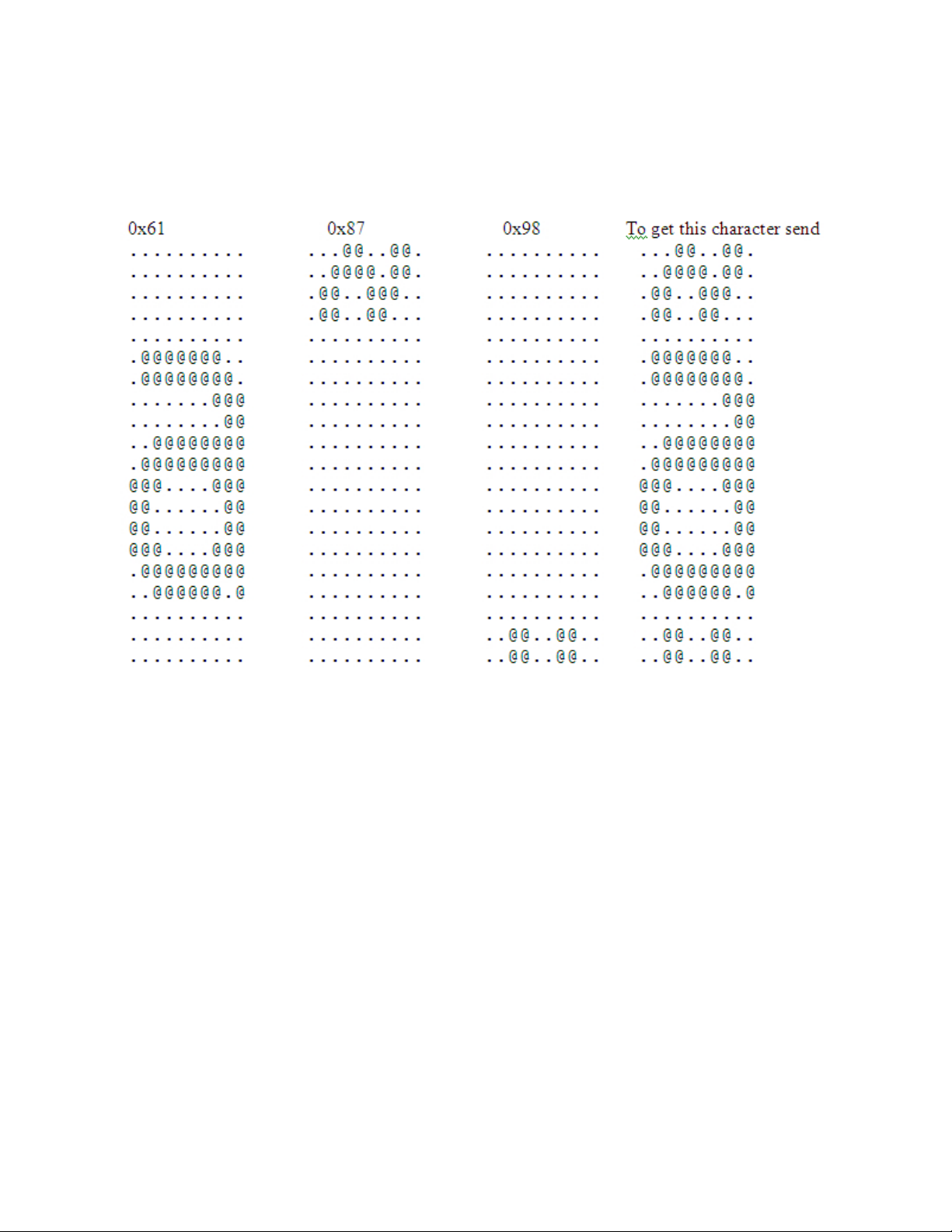
Remarks:
This is only supported on 2xR/1xR printers. It is intended for use with
languages that require “composite characters”.
Example. Send x`61; 08; 87; 08; 98' to get the composite character below.
Figure 2. Composite Characters
Return home (select print head location)
Syntax:
Where:
ESC < n or X'1B;3C;n'
n The print-head position:
00 Document Home Position
01 Open Document Throat Position
02 Reserved
03 Left Home Position
04 Re-find Document Home position. This can be used to
recover from a home error.
05 Register Document
v Close throat if open and document present
v Advance paper forward to first position if not open
06 Re-register the document if a document is in the printer;
brings it back to the first print position on the document.
72 SureMark 4610 Printers : Programming Guide for Models 1xR and 2xR
Page 89

Remarks:
Only valid at the beginning of the line. Only valid for impact print
stations.
Purpose:
To move the print head to the desired location.
Remarks:
Valid at the beginning of the line only. Valid in impact print stations only.
Paper cut/DI eject
Syntax:
ESC i or ESC m or X'1B;69 or 1B;6D'
Purpose:
To cut the paper in the customer receipt station, or eject the document in
the document insert station.
Remarks:
v This command is the equivalent of a form feed (0C) in the document
insert station but does not feed the customer receipt in the CR station.
v ESC i or X'1B69' does not increment status byte 6.
v ESC m or X'1B6D' does increment status byte 6.
Generate drive pulse for cash drawer
Syntax:
ESC p mn1n2or X'1B;70;m;n1;n2'
Where:
m The cash drawer number-0or1.
n1 Pulse width on time = (n1 × 2) milliseconds.
n2 Pulse width off time = (n2 × 2) milliseconds.
Purpose:
To open one of the cash drawers attached to the printer.
Remarks:
Printing will be suspended while a cash drawer is being opened.
Retrieve the flash storage
Syntax:
ESC 4 n1 n2 or X'1B;34;n1;n2'
Where:
n1 One-byte count of the bytes to be returned
n2 Three-byte address of the first byte to be returned
Purpose:
Retrieve data from user flash storage.
Remarks:
One byte will be returned if a byte count of X'00' is specified.
In many RS-485 printers, the number of bytes retrieved should be kept
under 200 to ensure that the system's receive buffer is not overrun.
Chapter 2. Communication parameters 73
Page 90

The valid address range for each SureMark depends on the model number
and which memory option, if any, is installed. Use “Retrieve size of user
flash storage” to determine the valid address range for your printer.
Retrieve size of user flash storage
Syntax:
ESC 4 x '08 FF FF FF' or X'1B;34;08;FF;FF;FF'
Purpose:
Retrieve the size of the user flash storage in the printer.
Remarks:
The size of the user flash storage will be returned in 8 bytes after the
printer status bytes. The data will be in the form of ASCII decimal data.
|
|
|
|
|
|
|
|
|
|
|
|
|
|
|
|
|
|
|
|
Prepare printer for shut down (S3)
Syntax:
ESC g or X'1B;67'
Purpose:
Prepares the printer to shut down.
Remarks:
The printer firmware tracks many things in internal memory, including
when to trigger low paper parameters and user statistics. These variables
must be stored in nonvolatile memory before the printers loses power to
keep accurate count of these statistics. When either the ECS g or a reset
command is sent to the printer, the printer will store all internal variables
into the flash memory. This should be sent to the printer by the system
unit before it enters S3 mode, where power is removed for I/O. When the
printer powers on (IPLs), a small amount of paper is fed (1/3 of an inch).
If ESC g is sent before the printer powers off, the paper will not feed when
the printer powers on.
Note: The ESC g command is only supported on the 2xR/1NR printers
after the 0C.xx release of the code. It is not supported on legacy
printers.
Asynchronous (real-time) commands
These commands are processed as soon as they are received. They do not go into
the printer buffer.
Note: These commands are not recognized when they occur in the middle of
another command. For example, sending this command after the second
byte of a 3-byte command, as in ESC J n.
Real-time requests
Syntax:
DLE ENQ m or X'1005:n'
Where:
m Specifies the ASCII command character
n - Specifies the hexadecimal command character
74 SureMark 4610 Printers : Programming Guide for Models 1xR and 2xR
Page 91

n Description
31 Release print buffer
32 Cancel print buffer
33 Undefined
34 EC request; send status
35 Undefined
36 Undefined
37 Undefined
38 Undefined
40 Reset printer
41 Enable unsolicited status
42 Disable unsolicited status
43 Disable transparent XON/XOFF
m n Description
1 31 Release the print buffer for printing. This should be sent
after an error has occurred and the print buffer is held. If
an error occurred during the transaction that was being
held, the printer sends back the line number with the error
and the error status. The system can then decide to cancel
or continue printing after the error is corrected. The
system uses this command to continue printing after the
error is corrected.
2 32 Cancel print buffer. This clears the print buffer of all data.
In RS-232 (EIA-232) mode, the user must wait for buffer
empty status (status byte 2, bit 6) before sending any more
commands.
Note: A status message is returned immediately after
execution of this command.
3 33 Undefined.
4 34 EC request - transmit printer status. Sends the printer's
status to the system. This command does not go into the
printer's data buffer but is processed immediately.
The printer status is returned in status bytes 1–16. See
Chapter 5, “Status information,” on page 89 for more
information.
Status byte 5, bit 1, will be set after the EC request has
been executed.
5-8 35-38 Undefined
@ 40 Reset the printer. The printer stops what it is doing and
goes through its reset routine. The print buffer is canceled
and all commands erased. All printer settings go back to
default values.
Chapter 2. Communication parameters 75
Page 92

m n Description
A 41 Enable unsolicited status.
Note: A status message is returned immediately after
execution of this command. To enable these status
messages, the Status Sent to System setup command must
be enabled. See “Status sent to system” on page 50.
B 42 Disable unsolicited status
C 43 Disable transparent XON/XOFF
Purpose:
To process a command immediately.
Remarks:
Either the Release print buffer or the Cancel print buffer command must be
used when the print buffer is held. If the printer is set to hold on error
then one of these commands must be used when the error condition is
cleared.
After the printer resets, it defaults to not sending status unless requested.
If an error occurs, the printer appears hung, unless a status is requested. If
unsolicited status is enabled, the printer sends the error to the system as
soon as it occurs.
Note: If transparent XON/OFF is disabled, X'10', X'11', and X'13' can be
imbedded in returned status and data. To re-enable the printer, the
printer must be reset.
Data buffer management and batch printing
Marker command
Syntax
ESC = marker or X'1B 3D' marker'
Where:
marker = 1 byte marker: 0x00 and 0x01 markers are reserved.
Purpose
To allow the driver to monitor how much of the data in the printer's buffer
has executed. The EC Level command returns status with the EC bit set. If
you want to know when a specific command has finished execution, a
buffered EC level request could be sent following the command. When
status is returned with the EC level bit set, then the previous command has
been completed.
Remarks:
The marker will be sent as status byte #4 in place of the EC level of the
code, and Status Byte 9, bit #1 will be set to indicate that the EC level has
been replaced by the marker for this status. The status with the marker
will be sent when all commands received before it has been processed. If
only a partial line is sent to the printer (characters without a line feed
command), the marker will be sent before the line gets printed.
Example:
LINE 1 FGHIJKLMNOPQRSTUVWXYZ1234567890x'0a'
LINE 2 FGHIJKLMNOPQRSTUVWXYZ1234567890x'0a'
LINE 3 FGHIJKLMNOPQRSTUVWXYZ1234567890x'0a'
76 SureMark 4610 Printers : Programming Guide for Models 1xR and 2xR
Page 93

0x'1B3D04'
LINE 4 FGHIJKLMNOPQRSTUVWXYZ1234567890x'0a'
LINE 5 FGHIJKLMNOPQRSTUVWXYZ1234567890x'0a'
LINE 6 FGHIJKLMNOPQRSTUVWXYZ1234567890x'0a'
LINE 7 FGHIJKLMNOPQRSTUVWXYZ1234567890x'0a'
LINE 8 FGHIJKLMNOPQRSTUVWXYZ1234567890x'0a'
0x'1B3D05'
v After the first three lines, the printer will transmit back status with the
normal printer status: Status Byte 4 = x'04'.
v After the 8th line, the printer will send back status with Status Byte 4 =
0x05.
Reset line count
Syntax:
ESC 6 or X'1B36'
Purpose:
Resetting the line count lets the system track the print line where an error
occurs.
Remarks:
The line count is incremented at every print command. The count is sent in
every status message to the system. The count can go to 256 (X'FF'), when
it rolls back to 0. (See “Print character commands” on page 64.)
Disable line count
Syntax:
ESC 8 n or X'1B;38'n
Where
v n = 1, disable line count
v n = 0, enable line count
Purpose:
To temporarily not increment the line count. This can be used when
printing predefined messages, if the number of lines embedded in the
message is unknown.
Hold printing until buffer is released
Syntax:
ESC 7 or X'1B37'
Purpose:
If the system cannot send data to the printer at a speed needed to keep the
printer in constant motion, it can hold the printer queue until it sends all
data lines for a transaction.
Remarks:
The printer must be printing one line while processing the next line. If the
printer is unable to completely process a line, the print speed reduces to
half.
The line count is reset when the buffer is held.
Chapter 2. Communication parameters 77
Page 94

Release print buffer
Syntax:
DLE ENQ 1 X'10;05;31''
Purpose:
To release the print buffer for printing
Remarks:
If an error occurs during the transaction that was being held, the printer
will send back the line number it occurred on with the error status. The
system can then decide to cancel or continue the printing when the error is
corrected. The command will continue the printing after the error is fixed.
78 SureMark 4610 Printers : Programming Guide for Models 1xR and 2xR
Page 95

Chapter 3. Page mode printing commands
This section describes the page mode commands.
Select page mode
Syntax:
ESC L or X'1B;4C'
Remarks:
v Enables page mode printing.
v Supported on thermal station only.
v Starting position is set by Set printable area X'1B;57.' and Set print direction
X'1B;54.' commands.
v Intercharacter spacing X'1B;20;n' and line spacing X'1B;31', X'1B;32',
X'1B;33' commands are set independently for page mode and standard
mode.
v The following commands are allowed:
– Rotate characters
– Set alignment
– Set/Clear upside-down
– Set margins
Select standard mode
Syntax:
ESC O or X'1B;4f'
Remarks:
v This command is effective in page mode only.
v Data buffered in page mode is cleared.
v This command sets the print position to the beginning of the line.
Select printable area
Syntax:
ESC X or X'1B;58;x;y;dx;dy'
Where:
v x, y
v dx, dy
Remarks:
v When sent in standard mode, this command sets the printable area for
v If the starting position (x, y) is outside the maximum range, the entire
– Two-byte horizontal and vertical starting position (in dots)
– Two-byte horizontal and vertical printing area (in dots)
page mode, but has no effect on standard mode printing.
command is ignored.
© Copyright IBM Corp. 2008, 2011 79
Page 96
v If the printing area is defined outside the maximum page size, the
printing area is limited to the page size.
v Maximum page size is 576 dots in the horizontal direction, and 800 dots
in the vertical direction (except Models Tx8 and Tx9, which is 1250 dots
in the vertical direction).
Select printing direction/position
Syntax:
ESC T n or X'1B;54;n'
Where:
n
Table 14. Print direction
n = Direction / position
X'00' Left to right / top left
X'01' Bottom to top / bottom left
X'02' Right to left / bottom right
X'03' Top to bottom / top right
Remarks:
When sent in standard mode, this command sets the print direction for
page mode, but has no effect on standard mode printing.
Starting position is within the printable area defined by the Select printable
area command (X'1B;58...)'.
Set vertical position
Syntax:
GS $ y or X'1D;24;y'
Where:
y is a two-byte vertical printing position (in dots)
Remarks:
v Applies to page mode only.
v Moves the printing position to the specified dot position perpendicular
to the printing direction specified by the Select printing direction
command. If printing direction is bottom-to-top, or top-to-bottom, this
command adjusts the printing position in the horizontal direction.
v If the value of y is outside the specified printable area, this command is
ignored.
Set relative vertical position
Syntax:
GS \ y or X'1D;5C;y'
Where:
y is the two-byte vertical printing position (in dots).
Remarks:
v Applies to page mode only.
80 SureMark 4610 Printers : Programming Guide for Models 1xR and 2xR
Page 97

v Moves the printing position the specified number of dots from the
current print position, in the direction perpendicular to the printing
direction specified by the Select printing direction/position command
(X'1B;54...'). If the print direction is bottom-to-top, or top-to-bottom, this
command adjusts the printing position in the horizontal direction.
v If the value of y is outside the specified printable area defined by the
Select printable area command, this command is ignored.
v If y is a negative value, the current print position will move in the
opposite direction.
Set left margin position (standard mode), set absolute print position (page mode)
Syntax:
ESC $ n1 n2 or X'1B;24;n1;n2'
Where:
v n1 is the high-order byte of the dot offset from the beginning of the print
line.
v n2 is the low-order byte of the dot offset from the beginning of the print
line.
Default:
n1 =0,n2 =0
Remarks:
v In the thermal station, 1 mm = 8 dots.
v In the impact station, 1 inch = 150 half-dots (75 dots).
v n1 and n2 are hex values. Convert each to decimal, and use this formula
to get the decimal equivalent: (n1 x 256) + n2.
v The maximum value in the thermal CR station is 576. The maximum
value in the impact DI station is 474.
v In the CR station, this number is rounded back to a factor of 8.
v If the n1,n2 value exceeds the maximum, it is ignored.
v This command should be sent only after the command that selects the
station, Set print station (ESC c1 n).
v In Page mode, the printing position is moved the specified number of
dots from the beginning of the print line, in the same direction as
printing, specified by the Select printing direction/position command
(X'1B;54...'). If the print position is bottom-to-top, or top-to-bottom, this
command adjusts the print position in the vertical direction.
v This is a one-time adjustment on the current line. If this command
moves the print position outside the printable area specified by the Select
printable area command, it is ignored.
Set relative horizontal position
Syntax:
Where:
ESC <5C>h n1 n2 or X'1B;5C;n1;n2'
v n1 is the high-order byte of the dot offset, relative to the left margin in
standard mode or the current print position in page mode.
Chapter 3. Page mode printing commands 81
Page 98

default:
Remarks:
Set printing position
Syntax:
v n2 is the low-order byte of the dot offset, relative to the left margin in
standard mode or the current print position in page mode.
n1 =0,n2 =0
v In the thermal station, 1 mm = 8 dots.
v In the impact station, 1 inch = 150 half-dots (75 dots).
v n1 and n2 are hex values. To get the decimal equivalent, convert each to
decimal, and then use this formula: (n1 x 256) + n2.
v To move the position to the left, use a negative number.
v If this number plus the left margin exceeds the printable area, the
command is ignored.
v In the CR station, this number is rounded back to factor of 8. See the Set
left margin position command for more information.
v When printing in page mode, this is a one-time adjustment on the
current line. If this command moves the current print position outside
the printable area defined by the Select printable area command, the
command is ignored.
GS ] xyor X'1D;5D;x;y'
Where:
v x is the two-byte horizontal position, with respect to the paper,
regardless of printing direction.
v y is the two-byte vertical position, with respect to the paper, regardless
of printing direction.
Remarks:
v This command allows complete control of the printing position with a
single command.
v If either parameter is outside the printable area defined by the Select
printable area command, the command is ignored.
Print, form feed and cut the paper
Syntax:
FF or X'0C'
Remarks:
v In standard mode, the data in the print buffer feeds the paper in the CR
station or DI station by a preset amount, until the document exits the
feed rollers. If a cutter is available (CR station only), it cuts the paper.
v In page mode, the printer prints the page, then returns to standard
mode. The page loaded in the printer's buffer is cleared. The paper is
not cut.
82 SureMark 4610 Printers : Programming Guide for Models 1xR and 2xR
Page 99

Print page in page mode
Syntax:
ESC FF or X'1B 0C'
Remarks:
v In standard mode, this command is ignored.
v In page mode, this command prints the page that is loaded in the
printer. The page remains loaded in the printer's buffer and the printer
remains in page mode. This should be used for repeatedly printing the
same page, or if there is a template that is filled in with each printout.
Clear print data in page mode
Syntax:
CAN or X'18'
Remarks:
This command deletes all print data in the current printable area of the
page stored in the print buffer.
Chapter 3. Page mode printing commands 83
Page 100

84 SureMark 4610 Printers : Programming Guide for Models 1xR and 2xR
 Loading...