

Ibiza MUSHROOM-LED (15-1084), MUSHROOM-LED Instruction Manual
© Copyright Lotronic 2009
1
LLEEDD MMUUSSHHRROOOOMM EEFFFFEECCTT
GB – INSTRUCTION MANUAL
F - MANUEL D’UTILISATION
D - BEDIENUNGSANLEITUNG
Mod. MUSHROOM-LED (15-1084)

GB
Preface
Thank you for using our LED mushroom IBIZA LIGHT. For your safety, please read the User’s Manual carefully
before your operation.
Note:This Manual includes the important information of installation, operation and safety instruction. Please install
and operate as requested in the Manual, meanwhile, please keep the manual for any unexpected requirement.
This Manual includes the important information of installation and operation. Please install and operate the light
according to the instructions strictly. And it must be power off when open the light or before repair.
A. Please read the complete contents of this manual. please keep this manual attach with the light for any
preview
B: In order to make sure the correct and safety installation. operation and maintenance, well know and follow to
the instructions of Manual is necessary.
CWe will not take any responsibility to the light damage. property loss or body injure which caused by the
incorrect installation. operation and maintenance.
NOTICE: The data which inside the Manual maybe changed due to the continuous improvement, and we’ll not
make another notice. We will keep the right to any specification update during improvement
Warning: If the protection screen. Lens or UV screen got a visible damage, e.g. scratch or chasm.
Unpacking Instructions
Please check if all the contents are completed after unpacking, then, check if the light is undamaged. Please you
can keep the original package and return to the factory if it’s damaged
3. AC Power: Check if the voltage is accordance with the rated power.
4. Safety Specifications: All the safety items of operation (includes installation) and before operating.
Unpacking the light case and take out all the accessories and open the poly package, take out the light from
the flight case, and put it in a certain platform for operation.
This device for indoor use only. The protection grade is: IP20. The light must keep dry and avoid to use under
the Moist. Overheat or Dusty surroundings. And keep the light far away from the water or other liquid.
Installing of the light must keep a distance with any flammable objects by 1M at least.
Please never install the light on the surface of the flammable objects.
The installation, operation and maintenance must be managed by the qualified professional, and make sure to
operate it under the instruction of the Manual.
Make sure the work environment temperature of the light maximum 45°, and minimum -15°C
The temperature of the light surface will up to 130°C even under the normal cooling, so never touch it by
hand.
The light was designed by electric shock protection type, and must connect to the power supply system which
well earthed. Furthermore, the ground wire of the light must connect to the ground wire of the power supply
system, ground wire interface of the light must well connect with the light body (or light must well earthed)
Please check if the voltage is accordance with the rated power before installing.
Please never use the power cable which was damaged the insulation cover, meanwhile; never put the power
cable on any other wire. Please pull out the power cable by handle the plug when light is stop working or
cleaning, never pull out it roughly or handle the wire directly.
The light doesn’t include any spare parts for repair; please check if all the parts are well installed and screws
are drove tightly before operating. It’s prohibited to use the light when the cover is opened.
Notice: Please make sure it’s power off before any installation. repair and clean!
1. Introduction
2. Technical Features
(1) Control channel: 9 DMX channels
(2) Color: RGB three basic color, color shade
(3) Operating modes: standard DMX512 controller control mode
(4) Other function: rotate angle 180o , master and slave mode, sound control
(5) Appearance: metal shell, streamlined designs.
(6) Working environment: indoor, -15 ~ 40
(7) IP degree: IP20
© Copyright Lotronic 2009
2
III. Technology Parameter
Voltage...................................AC220~240V 50Hz (110V-120V 60Hz, can be select)
Power................................................................................................................... 35W
Fuse: .................................................................................................... F1A, 250VAC
LED lamp: ................................................................................... 6X3W (R2. G2. B2)
Packing Size ................................................................................... 290×290×380mm
N/W ...................................................................................................................... 3Kg
G/W................................................................................................................... 3.6Kg
Installation
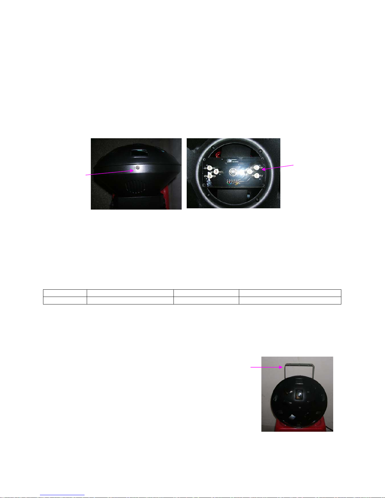
Install/replace LED lamp
First, after unscrewed the screw at the head of shell and then pull out it. You can see the LED. If found the LED
are not bright, then replace them. Installation method is just the opposite.
© Copyright Lotronic 2009
3
6LED lamp
Un
screwed the
screws
Warning
1: The light powe
r supply must be disconnected when replacement of the LED does not bright
2: you can repair the light before you must use a thermostat with anti-static electric iron, and wear anti-static rings
2. Power supply, wire Connection
Using a dedicated plug to connect the LED mini mushroom light and power. LED mini mushroom should pay
attention to whether the voltage and frequency between signs and on the power supply are the same or not.
Suggested that each light has a separate power supply switch, this can be turned on or off at random for each
LED mini mushroom. The LED mini mushroom selection of input voltage and frequency parameters as follows:
Voltage AC220V240V Frequency 50Hz
Voltage AC110V240V Frequency 60Hz
If the power cable is damaged, please contact the area agents or ask professional to replace; please use the
same specification cable when you replace the power cable.
Tip: When connecting the power, ground wire must (yellow / green color wire) safety grounding, electrical
installation must comply with all relevant standards.
3. Fixed installation of lighting (including light hook and safety rope how to use)
Hook installation
Before po
sitioned the light, ensure the stability of the installation site. In the
reverse hanging installation, use two sets of M10 bolts with a professional big
hook, link the hanging screw hole on the bottom of the light, must be ensure that
the light will not fell down from support rack, through the support rack and light
hand use the safety rope for auxiliary lifting handle to ensure safety, to prevent
the light falling and sliding. Light in the installation, the bottom prohibit
pedestrians. Safety rope regularly checked whether there is wear and tear,
whether there is loose hook. The manufacturer does not take any responsibility if
the light falling because hanging installation is not stable.
Warning
1. Hoo
k use only for light lifting.
2. Hook as a handle move the light to prohibit, carrying, please use the handle.
Operation
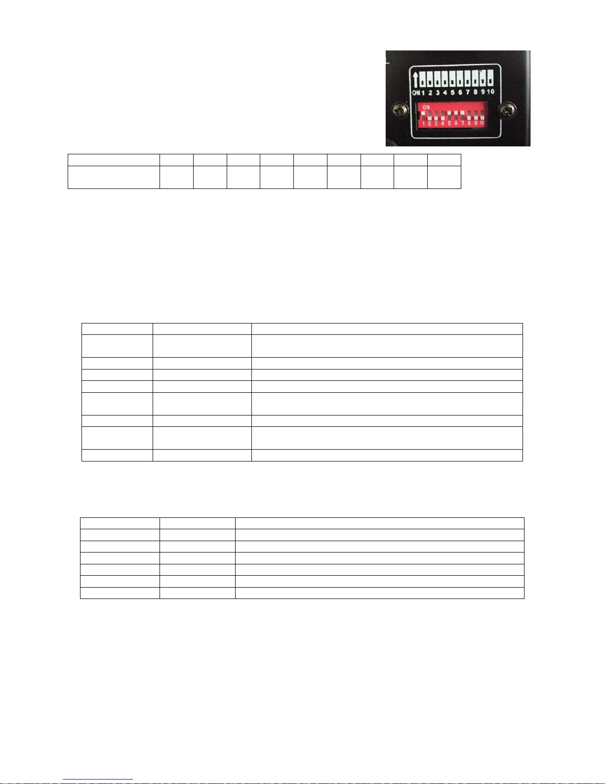
DMX Address Co
de Setting
Every light should be set with DMX address code when you are using the
controller to control multi lights, it is used to receive the signal from the
controller. Since the product uses "address code dial code" set the address
code, so each dial code corresponding to address values are as follows:
Dial code 1 2 3 4 5 6 7 8 9
Corresponding to
address code value
1 2 4 8 16 32 64 128 256
The present address code of the light =(address code of last light)+(channel quantity of the light).The light with 9
Channels, so it should be under the “16channel” control mode, the DMX address code of the first light is “1” the
corresponding dial code is "1" (or all of the dial code not dial),the second should be: 1+16=17; the corresponding
dial code is "1 +5", the third light address value is 1+16 * 2 = 33, the corresponding dial code is "1 +6 ", The fourth
should be 1 +16 * 3 = 49, the corresponding dial code is" 1 +5 +6 ", analogously.
Auto-mode
Dial the code 10 and 8 to ON, LED mini mushroom light in auto running mode. The dial codes 1, 2 and 3 are the
conversion of the different modes of auto running. Following the list:
DIP number Function description Remark
10+8 Auto
Auto-running show (include shade. strobe. change color and so
on)
10+8+1 R shade
10+8+2 G shade
10+8+3 B shade
10+8+2+1
RGB
shade(speed1fast)
10+8+3+1 RGB shade(speed2)
10+8+3+2
RGB
shade(speed3slow)
10+8+3+2+1 R+G+B shade
Sound control mode
Dial the code 10 and 7 to ON, LED mini mushroom light will be in sound control mode. The dial code 1. 2. 3. 4
and 5 are the conversion of the different modes of sound control mode.
DIP number Function Remark
10+7 Sound mode1
10+7+1 2
10+7+2 3
10+7+3 4
10+7+4 5
10+7+5 6
Setting master machine is when dial the code 10 to ON, control the slave machine can by DMX connect interface.
All dial code to OFF, when dial 10 to OFF, 1 to 9 is the light address code setting (8421 binary code format), are
all OFF, the address is 001.
Master-slave mode
Setup master machine and dial code 10 to ON, can control slave machine by DMX connect interface. All dial code
to OFF when slave machine receiving; 1-9 is the light address code setup (8421 Binary encoding format) when
dial 10 to OFF, the address code is 001 when all OFF.
Warm Tip: The light auto running effect, are selected from the control channel with the proceeds, so users can
use the DMX controller of have storage capabilities to make out the changers effect of your need.
© Copyright Lotronic 2009
4
DIP number Function description remark
10+1 R
10+2 G
10+3 B
10+2+1 R+G
10+3+1 R+B
10+3+2 G+B
10+3+2+1 R+G+B
Fixed color (away brightness)
10+8 Auto running
Auto running show(include shade. strobe. change
color and so on)
10+8+1 R shade
10+8+2 G shade
10+8+3 B shade
10+8+2+1 RGB shadespeed 1 fast
10+8+3+1 RGB shadespeed 2
10+8+3+2 RGB shadespeed 3 slow
10+8+3+2+1 R+G+B shade
Shade
10+9 RGB change each other
10+9+1 R strobe
10+9+2 G strobe
10+9+3 B strobe
10+9+4 R+B strobe
10+9+5 R+G strobe
10+9+6 G+B strobe
Strobe
10+9+2+1
R+G+B strobe(speed
adjustment)
(DIP3-DIP7) adjustment strobe speed
10+7 Sound control1
10+7+1 Sound control2
10+7+2 Sound control3
10+7+3 Sound control4
10+7+4 Sound control5
10+7+5 Sound control6
Appendix
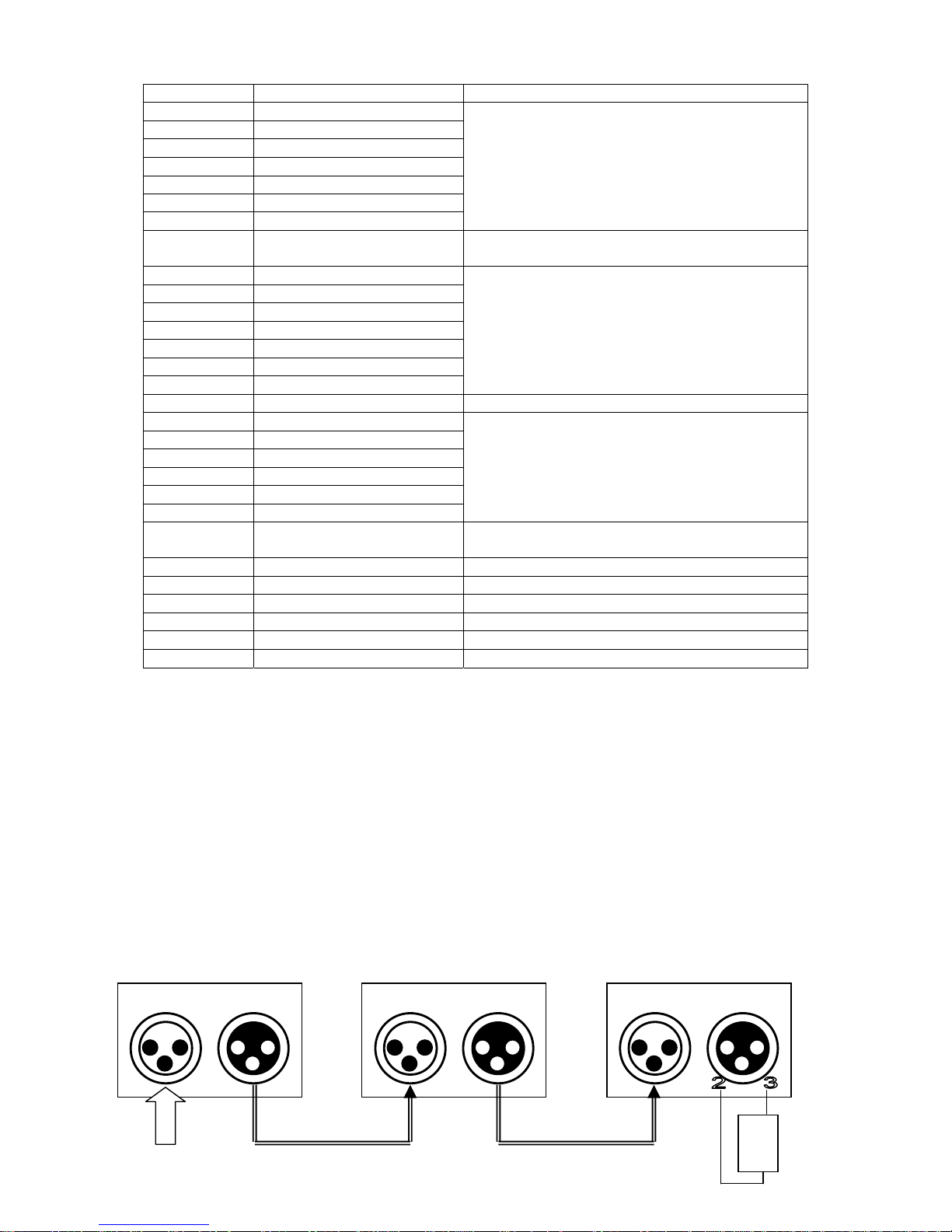
1. Usage of the Signal Cable. Connector
The connection between the output and input, it’s available to use the 3 pins XLR cable which provided by the
manufacturer. Signal cable from the DMX output of the controller to the input of the first master light, and connect
to the DMX input of second slave light from the DMX output of the first master light, analogously till connected all
the slave lights, and insert the last connector to the output of the final light.
If you want to prolong the connection of signal cable, the connection of the pins between male connector and
female connector should be:1 to 1; 2 to 2; 3 to 3,or it will cause communication interruption. Notice: the diameter
of core of every cable should be 0.5mm at least double core shelter cable should be used. The signal connecting
must use the attached 3 pins XLR cable. Notice, all the internal lead wire of the 3 pins XLR cable should not touch
to each other or connect to the connector.
The light is available to receive the DMX512 signal, connect the signal plug to the panel which marked with “IN”
and connect it to the next light. then, connect to the “IN” of next light from the “OUT”. The DMX signal terminal
organ is recommended when the lighting signal is connecting. It will avoid to damage the signal which caused by
the noise, DMX terminal organ is a XLR connector, connect with a 120Ω resistor between the pin 2 and pin 3 of
the XLR connector, and connect it to the last OUTPUT socket of the final light. Follow picture:
© Copyright Lotronic 2009
5
1
s
t
light
2
n
d
light
3
r
d
li
g
ht
IN OUT IN OUT IN OUT
DMX
120R
 Loading...