

Hyundai S2F57 AC300 Installation Instructions Manual
Genuine Accessories
Glasses Gloves
Mask Hearing Protection
Part Weight (Gross) FMVSS 110 Compliance Information
Technical Support
1 Read the entire Installation Instructions prior to beginning the installation of the part.
2
Make sure the vehicle is completely clean and dry in the area(s) the part is to be installed.
3 Ensure the vehicle is properly protected in the area(s) that the accessory is to be installed.
4 NEVER place tools on painted surfaces, seating surfaces, dash pad, console or floor carpet/mats.
5 Always wear appropriate personal protective equipment, including gloves, safety glasses, etc., when required.
6 Record radio presets prior to disconnecting battery power, if needed.
7 Roll down the driver's window and adjust the power seats (if applicable) prior to disconnecting battery power, if needed.
8
To prevent stress on the remote start wire harness, ensure the tilt steering column is fully extended before installing the kit.
9 Vehicle should be at room temperature.
10
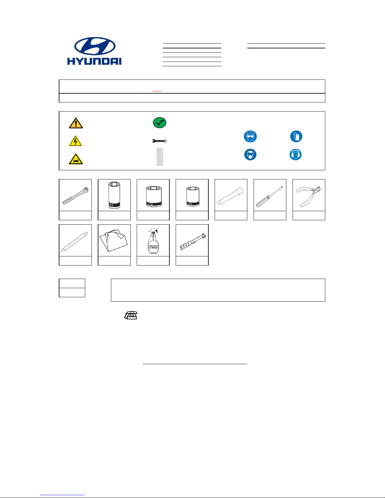
10mm Deep Well
Socket
8mm Socket
Extension
Wire Cutters
Trim Removal Tool
N
O
T
E
Denotes important information to be
reviewed during the step
Denotes cautions to be taken to avoid
vehicle and component damage
Ratchet
12mm Socket
Authorized dealers use:
Hours:
Clean Cloth
50/50 Isopropyl Alcohol
(70%) and Water Mix
Torque wrench
Notes to the installer:
Language
English
5/3/2018
Rev. Date
Accessory:
Vehicle Model:
Difficulty stated above reflects the minimum level of
expertise required to install the accessory:
( B )
Remote Engine Start - Key Start
(A) Customer
Santa Fe
Difficulty:
Part No.
Model Year
Copy OEM Logo Here (→)
2019~
S2F57 AC300
Note:
Basic Required Tools
(C) Master Technician or Specialist
(B) Dealer Technician
Instructional Symbols / Definitions
Application Notes
Denotes quality processes to be checked
prior to moving to the next step
Denotes personal protective equipment (PPEs) that
may be required for a step. Examples of safety
equipment icons noted below:
Denotes specific tools that are necessary
to complete a step
#2 Phillips
Screwdriver
Denotes cautions to be taken to avoid
physical injury or electronic component
damage
Vehicle must be equipped with mechanical key start.
Ensure vehicle does NOT have SMART KEY (PUSH BUTTON IGNITION SYSTEM).
Vehicle should be equipped with automatic transmission, power door locks, and power windows. If these features are not equipped on the vehicle, do not proceed with install.
(1) 855-225-7344
M~F - 9am~5pm Pacific Standard Time
The order of the disassembly and reassembly steps have been optimized for maximum efficiency and the correct
installation of the Remote Engine Start kit. Disassemble vehicle components (including harness connectors) and
install the kit components according to each step, as indicated. Avoid disassembling or reassembling any
components in advance to prevent unnecessary labor time and/or installation errors.
Denotes warnings that may lead to serious
physical injury or vehicle damage
0.87
0.39
lbs
kg
All dealers must determine if the weight they have added in the form of all options or accessories, when added to the weight of all Port/Dealer Installed
options or accessories, exceeds the lesser of 1.5% of GVWR or 100 lbs. If the additional weight does exceed the lesser of the indicated thresholds, a “Load
Carrying Capacity Reduced” label must be installed. A black, fine-point, indelible marker must be used to write by hand onto the label, the reduced carrying
capacity in kilograms or pounds, which is the total weight of all added options and accessories.
Load Label Part Number: NP070-09003
Revision Date
5/03/2018
Page 1 of 11
Genuine Accessories
No. No.
1 6
2 7
3 8
4 9
5
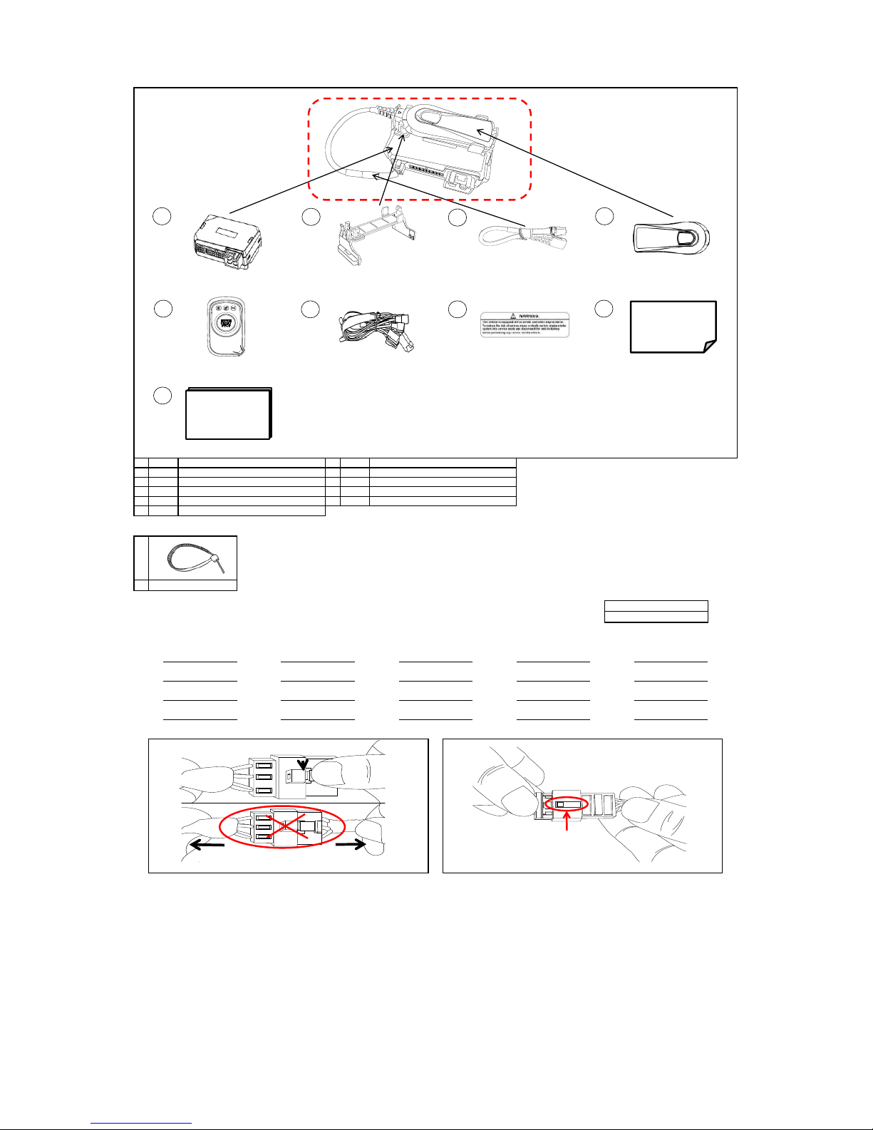
Hardware Kit Contents
9
* Indicates extra components intentionally included in kit as spares.
Follow instructions for proper placement of each component.
Radio Presets - record customer preset frequencies if disconnecting battery power
Disconnecting Connectors Locking Connectors
When disconnecting connectors, grasp the connectors, not the wire. When locking connectors, listen for a click indicating they are securely locked.
9
FM1
AM2
Special Instructions
A
FM9
AM3
FM3
1
Antenna Harness
FM2
Wire Tie*
SAT2
SAT3
SAT4
AM1
FM6
FM5
FM7
FM8
1
S/P: S2F57 AC230
2
1 Way Transmitter Fob
Qty
FM10
SAT1
S/P: S2F57 AC340
S/P: 1WF57 AC340
Kit Overview
S/P: S2F57 ACD10
Qty
Description
Control Module
1
Harness
SAT5
AM5
AM4
FM4
1
S/P: S2F57 AC120
S/P: A9F57 AC170
Hardware Total
11Antenna Bracket
Warning Label
Antenna1Owner's Guide
1
Quick Reference Guide
Description
9
Quick Reference
Guide
Owner's Guide
CLICK
NO GOOD
8
7
6
5
1
2
3
4
Locking Tab
Revision Date
5/03/2018
Page 2 of 11

Genuine Accessories
Remote Start Harness Connector Locations For Reference
N
O
T
E
N
O
T
E
1
WARNING! Shock Hazard. Do not touch vehicle's negative
battery terminal to vehicle's positive battery terminal. Serious
physical injury or electronic component damage may occur.
A. Remove the vehicle's Negative (-) Battery Cover.
B. Disconnect and isolate the vehicle's Negative (-) Battery Cable.
2
A. Lower the Driver's Door Window.
B. Move the Driver's Seat to the rearmost position.
C. Record all pre-set radio stations (if applicable).
D. Pull the Hood Lever to open the Hood.
Ratchet, Extension and 10mm Deep Socket
Negative Battery
Cable
Step 12
Ground
Steps 10 ~11
CAN Connectors
(Multi Box)
Steps 8 ~ 9
Ignition Connectors
Negative Battery
Cover
Revision Date
5/03/2018
Page 3 of 11
Genuine Accessories
N
O
T
E
N
O
T
E
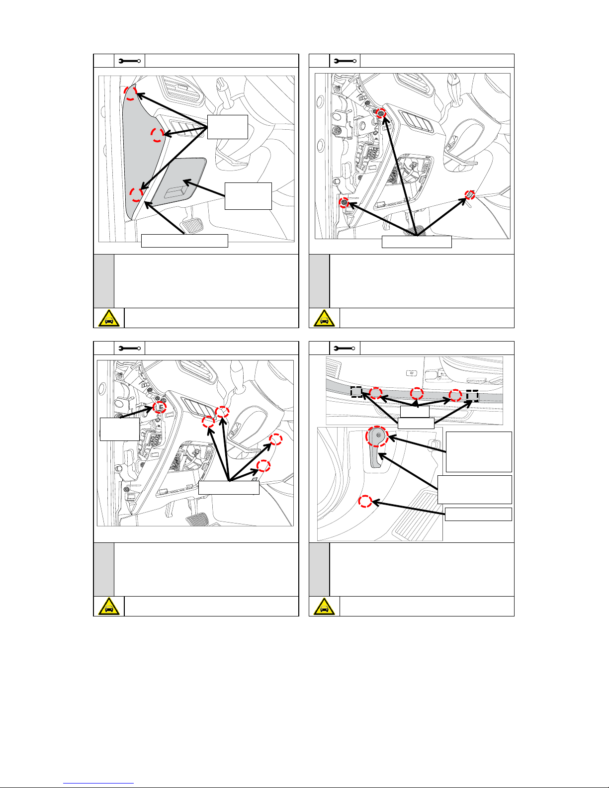
A. Remove the Fuse Panel Cover.
B. Gently pull the Weatherstrip back from the dash area.
C. Using a trim removal tool, remove the Driver’s Side Dash End Cap Panel
by prying outward to disengage the three (3) Pressure Clips.
D. Store the removed parts in a safe location for reinstallation.
N
O
T
E
#2 Phillips Screwdriver
5
4
Caution! Be careful not to damage the parts or clips during removal.
A. Using a Trim Removal Tool, release the Retaining Tab as shown.
B. By hand, dislodge the Lower Dash Panel.
C. Disconnect any Electrical Connectors including OBDII Connector from
the Lower Dash Panel, if applicable.
D. Store the removed part in a safe location for reinstallation.
Caution! Do not damage the Lower Dash Panel, OBDII Connector or
Electrical Connectors.
N
O
T
E
Caution: Do not damage the Dash Panel, Fuse Panel Cover or Dash End
Cap. Make sure no pressure clips remain in the dash board.
A. Dislodge the Weatherstrip from the Driver's Kick Panel along the Door
Threshold Panel.
B. Remove the Driver's Door Threshold Panel.
C. Remove the Hood Release Lever.
D. Remove the Driver's Kick Panel.
E. Store the removed parts in a safe location for reinstallation.
3
Trim Removal Tool
6
Trim Removal Tool
A. Using a Phillips Screwdriver, remove the two (2) phillips screws
from the side of the Lower Dash Panel as shown.
B. Using a Phillips Screwdriver, remove the one (1) phillips screw
from the bottom of panel as shown.
C. Store the removed screws in a safe location for reinstallation.
8mm Socket, Extension, Trim Removal Tool
Caution: Do not damage the Lower Dash Panel.
Pressure
Clips
Fuse Panel
Cover
Dash End Cap Panel
Phillips Screws
Pressure Clips
Retaining
Tab
Clips
Hooks
Press the 8mm
Socket with
Extension onto
the Tabs
Pry the Hood
Lever using a
Trim Removal Tool
Plastic Push Clip
Revision Date
5/03/2018
Page 4 of 11
 Loading...