

Page 1

’04 MATRIX_U (L/O 0307)
SECTION 1− 1
OPERATION OF INSTRUMENTS AND
CONTROLS
Overview of instruments and controls
Instrument panel overview 2. . . . . . . . . . . . . . . . . . . . . . . . . . . . . . . . . . . . .
Instrument cluster overview 4. . . . . . . . . . . . . . . . . . . . . . . . . . . . . . . . . . . .
Indicator symbols on the instrument panel 5. . . . . . . . . . . . . . . . . . . . . . .
2004 MATRIX from Oct. ’03 Prod. (OM12861U)
1
Page 2
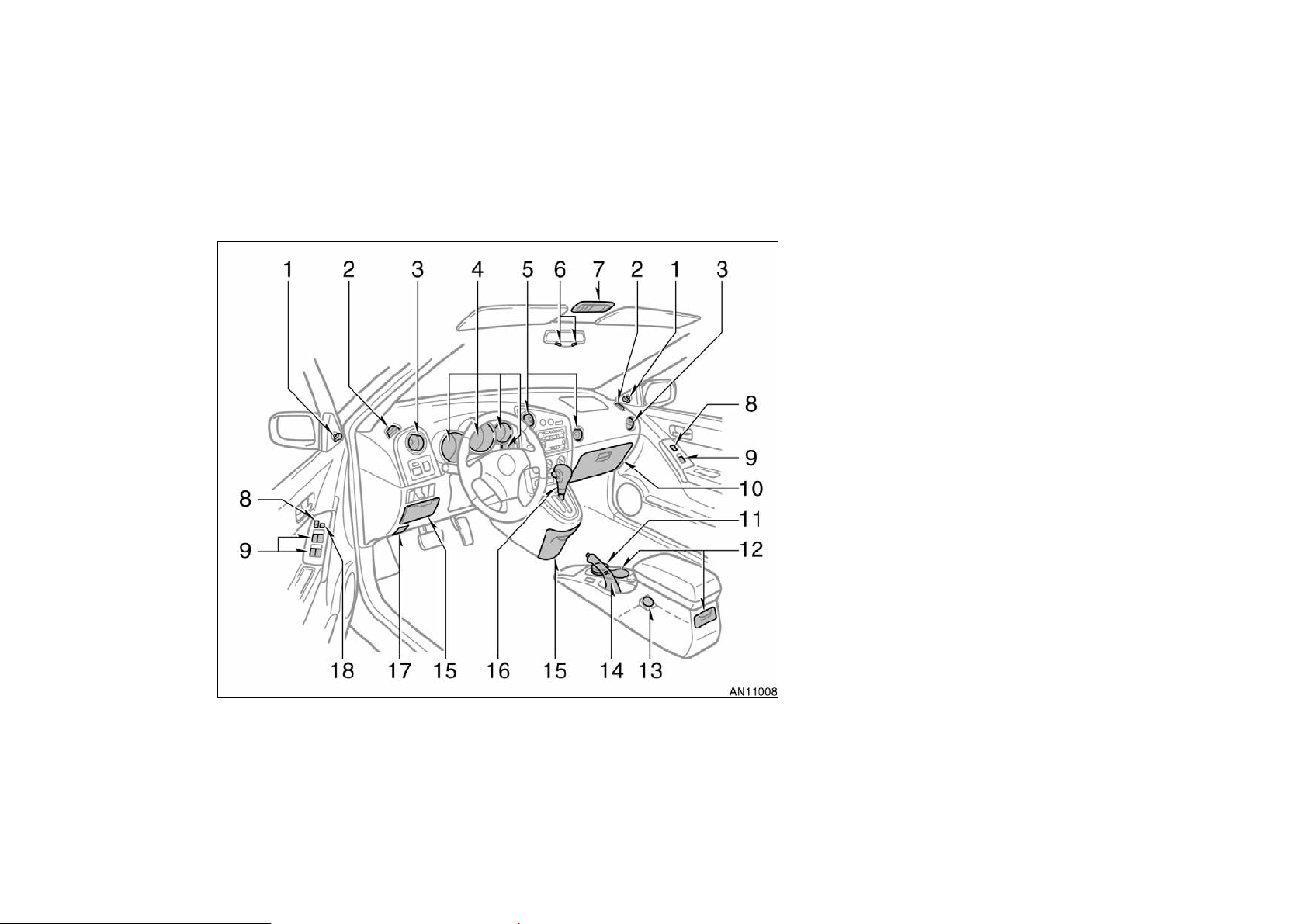
Instrument panel overview
’04 MATRIX_U (L/O 0307)
1. Rear view mirror remote control levers
2. Side defroster outlets
3. Side vents
4. Instrument cluster
5. Center vents
6. Personal lights
7. Electric moon roof switches and
personal light
8. Power door lock switches
9. Power window switches
10. Glove box
11. Portable ashtray
12. Cup holders
13. Power outlet (12 VDC)
14. Parking brake lever
15. Auxiliary boxes
16. Automatic transmission selector lever
or manual transmission gear shift lever
17. Hood lock release lever
18. Window lock switch
2
2004 MATRIX from Oct. ’03 Prod. (OM12861U)
Page 3
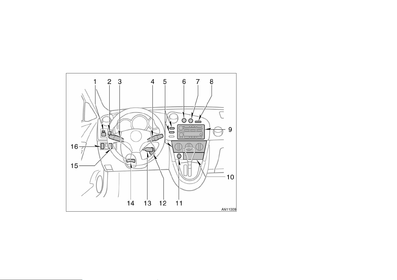
’04 MATRIX_U (L/O 0307)
1. Power rear view mirror control switches
2. Interior/instrument panel light control
dial
3. Headlight, turn signal and front fog
light switches
4. Wiper and washer switches
5. Air conditioning controls
6. Emergency flasher switch
7. Rear window defogger switch
8. Front passenger’s seat belt reminder
light
9. Car audio
10. Auxiliary box or power outlet (115 VAC)
11. Power outlet (12 VDC) or cigarette
lighter
12. Ignition switch
13. Cruise control switch
14. Tilt steering lock release lever
15. Toyota vehicle intrusion protection
system indicator light
16. Glass hatch opener switch
2004 MATRIX from Oct. ’03 Prod. (OM12861U)
3
Page 4
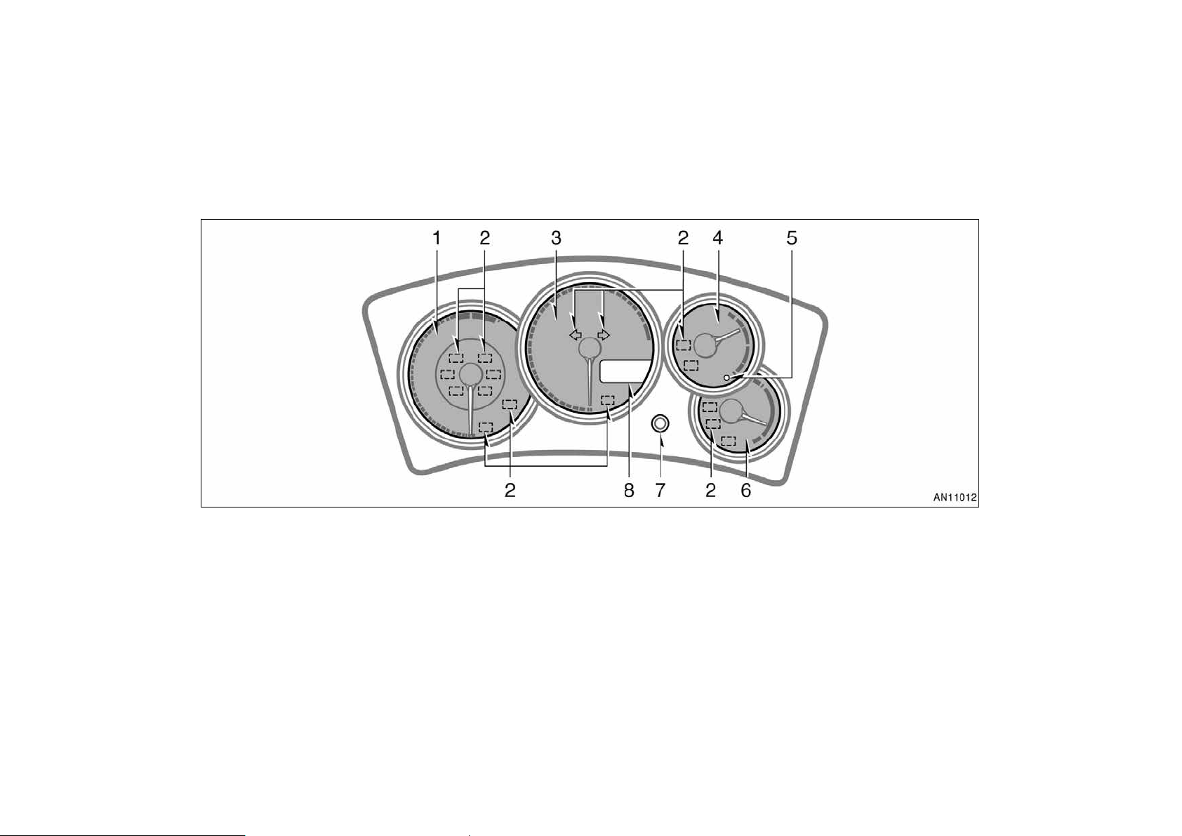
Instrument cluster overview
’04 MATRIX_U (L/O 0307)
1. Tachometer
2. Service reminder indicators and
indicator lights
3. Speedometer
4
4. Fuel gauge
5. Low fuel level warning light
6. Engine coolant temperature gauge
7. Trip meter reset knob
8. Odometer, two trip meters and outside
temperature display
2004 MATRIX from Oct. ’03 Prod. (OM12861U)
Page 5
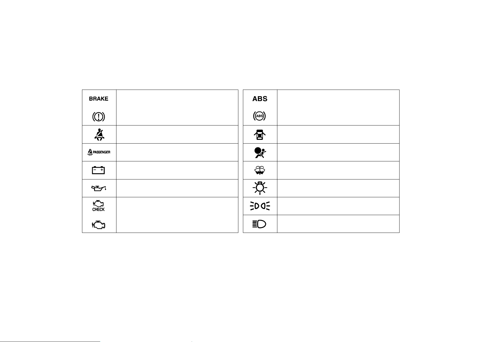
Indicator symbols on the instrument panel
’04 MATRIX_U (L/O 0307)
∗
or
Brake system warning light
Driver ’s seat belt reminder light
Front passenger’s seat belt reminder light
Discharge warning light
Low engine oil pressure warning light
1
∗
1
∗
1
∗
1
∗
1
or
Anti−lock brake system warning light
∗
Open door warning light
SRS warning light
1
∗
1
Low windshield washer fluid level warning light
∗
∗
1,
3
Headlight low beam indicator light
∗
1
Tail light indicator light
∗
or
Malfunction indicator lamp
1
Headlight high beam indicator light
2004 MATRIX from Oct. ’03 Prod. (OM12861U)
5
Page 6
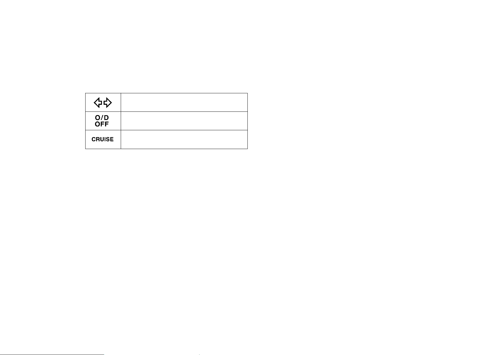
Turn signal indicator lights
Overdrive−off indicator light
∗
Cruise control indicator light
∗
1
: For details, see “Service reminder indicators and warning
2
buzzers” on page 91 in Section 1−6.
∗
2
: If this light flashes, see “Cruise control” on page 105 in
Section 1−7.
∗
3
: This symbol equipped only on vehicles sold in Canada.
’04 MATRIX_U (L/O 0307)
6
2004 MATRIX from Oct. ’03 Prod. (OM12861U)
Page 7

’04 MATRIX_U (L/O 0307)
SECTION 1− 10
OPERATION OF INSTRUMENTS AND
CONTROLS
Other equipment
Clock 154. . . . . . . . . . . . . . . . . . . . . . . . . . . . . . . . . . . . . . . . . . . . . . . . . . . . . .
Cigarette lighter and portable ashtray 154. . . . . . . . . . . . . . . . . . . . . . . . .
Power outlets (12 VDC) 155. . . . . . . . . . . . . . . . . . . . . . . . . . . . . . . . . . . . .
Power outlet (115 VAC) 156. . . . . . . . . . . . . . . . . . . . . . . . . . . . . . . . . . . . . .
Compass 157. . . . . . . . . . . . . . . . . . . . . . . . . . . . . . . . . . . . . . . . . . . . . . . . . .
Glove box 161. . . . . . . . . . . . . . . . . . . . . . . . . . . . . . . . . . . . . . . . . . . . . . . . . .
Auxiliary box 161. . . . . . . . . . . . . . . . . . . . . . . . . . . . . . . . . . . . . . . . . . . . . . .
Rear console box 162. . . . . . . . . . . . . . . . . . . . . . . . . . . . . . . . . . . . . . . . . . .
Cup holders 164. . . . . . . . . . . . . . . . . . . . . . . . . . . . . . . . . . . . . . . . . . . . . . . .
Seatback tables 164. . . . . . . . . . . . . . . . . . . . . . . . . . . . . . . . . . . . . . . . . . . .
Luggage storage boxes 165. . . . . . . . . . . . . . . . . . . . . . . . . . . . . . . . . . . . .
Tie−down hooks and tire tie−down belts 166. . . . . . . . . . . . . . . . . . . . . . .
Luggage deck rails 167. . . . . . . . . . . . . . . . . . . . . . . . . . . . . . . . . . . . . . . . .
Luggage cover 168. . . . . . . . . . . . . . . . . . . . . . . . . . . . . . . . . . . . . . . . . . . . .
Floor mat 169. . . . . . . . . . . . . . . . . . . . . . . . . . . . . . . . . . . . . . . . . . . . . . . . . .
153
2004 MATRIX from Oct. ’03 Prod. (OM12861U)
Page 8
Clock
Type A
Type B
’04 MATRIX_U (L/O 0307)
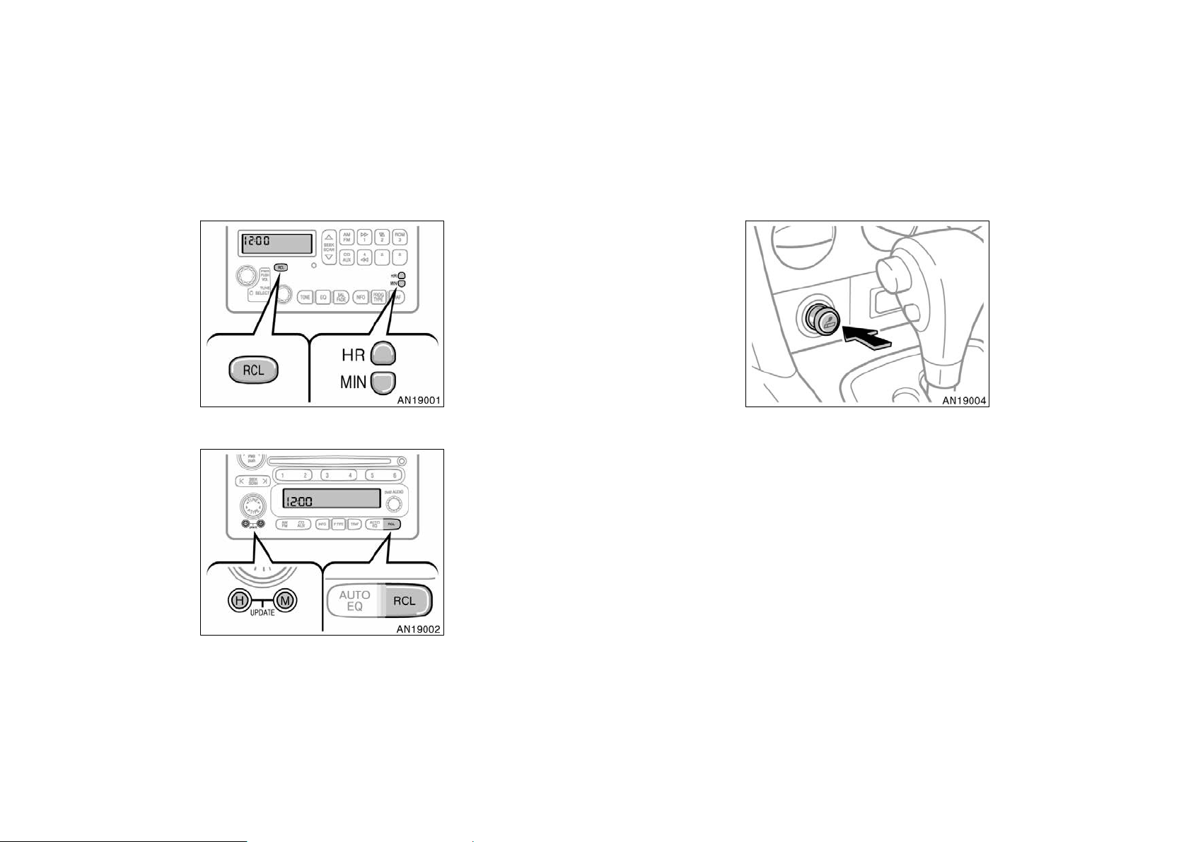
The digital clock indicates the time
when the key is in the “ACC” or “ON”
position. Even when the ignition switch
is off, you can turn on the clock display for a few seconds by pushing the
“RCL” button.
Type A—To set the time, push and hold
the “HR” or “MIN” button until the “:”
starts flashing. Then set the time by pushing the “HR” (hour) and the “MIN” (minute)
buttons. If the time is before 12 noon,
“AM” appears on the display when the
time being set.
Type B—To set the time, push and hold
the “H” or “M” button until the “:” starts
flashing. Then set the time by pushing the
“H” (hour) and the “M” (minute) buttons.
When the time is being set, “AM” or “PM”
appears on the display.
RDS CLOCK UPDATE FUNCTION
You can update the clock with RDS
(Radio Data System) data. Push and hold
the “HR” and “MIN” (type A) or “H” and
“M” (type B) buttons at least 2 seconds
while receiving an RDS station. “TIME
UPDATED” will appear on the display with
a beep and the clock will be updated. If
setting could not be completed
successfully, “NO UPDATED” will appear
on the display.
Cigarette lighter and portable
ashtray
CIGARETTE LIGHTER
To use the cigarette lighter, press it in.
After it finishes heating up, it automatically pops out ready for use.
If the engine is not running, the key must
be in the “ACC” position.
Do not hold the cigarette lighter pressed
in.
Use a Toyota genuine cigarette lighter or
equivalent for replacement.
154
2004 MATRIX from Oct. ’03 Prod. (OM12861U)
Page 9
’04 MATRIX_U (L/O 0307)
CAUTION
To reduce the chance of injury in
case of an accident or sudden stop
while driving, always completely close
the ashtray after use.
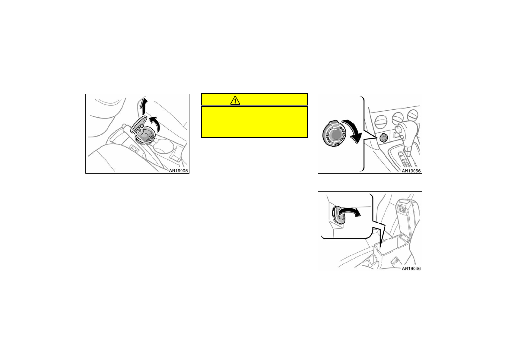
Power outlets (12 VDC)
PORTABLE ASHTRAY
The ashtray can be removed and used
outside the vehicle. To use the ashtray,
open the lid.
When finished with your cigarette, thoroughly extinguish it in the ashtray to prevent other cigarette butts from catching
fire. After using the ashtray, push it back
in completely.
To remove the ashtray, pull it out from the
front cup holder.
Instrument panel
Rear console box
155
2004 MATRIX from Oct. ’03 Prod. (OM12861U)
Page 10
The power outlets are designed for
power supply for car accessories.
The key must be in the “ACC” or “ON”
position for the power outlets to be used.
NOTICE
z To prevent the fuse from being
blown, do not use the electricity
over the total vehicle capacity of 12
V/120W (instrument panel and rear
console box outlets together).
z To prevent the battery from being
discharged, do not use the power
outlets longer than necessary when
the engine is not running.
z Close the power outlet lids when
the power outlets are not in use.
Inserting a foreign object other than
the appropriate plug that fits the
outlet, or allowing any liquid into
the outlet may cause electrical failure or short circuits.
’04 MATRIX_U (L/O 0307)
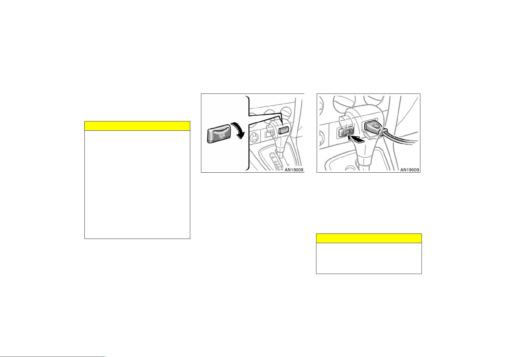
Power outlet (115 VAC)
This power outlet is designed for use
as a power supply for electric appliances in the vehicle.
The key must be in the “ON” position for
the power outlet to be used.
The maximum capacity for this power outlet is 115 VAC/100W. If you attempt to
use an appliance that requires more than
115 VAC or 100W, the protection circuit
will activate and cut the power supply.
The power supply will restart automatically
when you use an appliance that operates
within the 115 VAC/100W limits.
To use the power outlet, push the main
switch on the instrument panel.
An indicator light will illuminate to indicate
that the power outlet is ready for use.
Push the main switch once again to turn
the power outlet off. When the power outlet is not in use, make sure that the main
switch is turned off.
NOTICE
z To prevent the battery from being
discharged, do not use the power
outlet longer than necessary when
the engine is not running.
156
2004 MATRIX from Oct. ’03 Prod. (OM12861U)
Page 11
z Close the power outlet lid when the
power outlet is not in use. Inserting
a foreign object other than the appropriate plug that fits the outlet
may cause electrical failure or short
circuits.
The power outlet is not designed for
the following electric appliances even
though their power consumption is under 115 VAC/100W. These appliances
may not operate properly.
D Appliances with high initial peak watt-
age: cathode−ray tube type televisions,
compressor−driven refrigerators, electric
pumps, electric tools, etc.
D Measuring devices which process pre-
cise data: medical equipment, measuring instruments, etc.
D Other appliances requiring an extremely
stable power supply: microcomputer−
controlled electric blankets, touch sensor lamps, etc.
Certain electrical appliances may cause
radio noise.
’04 MATRIX_U (L/O 0307)
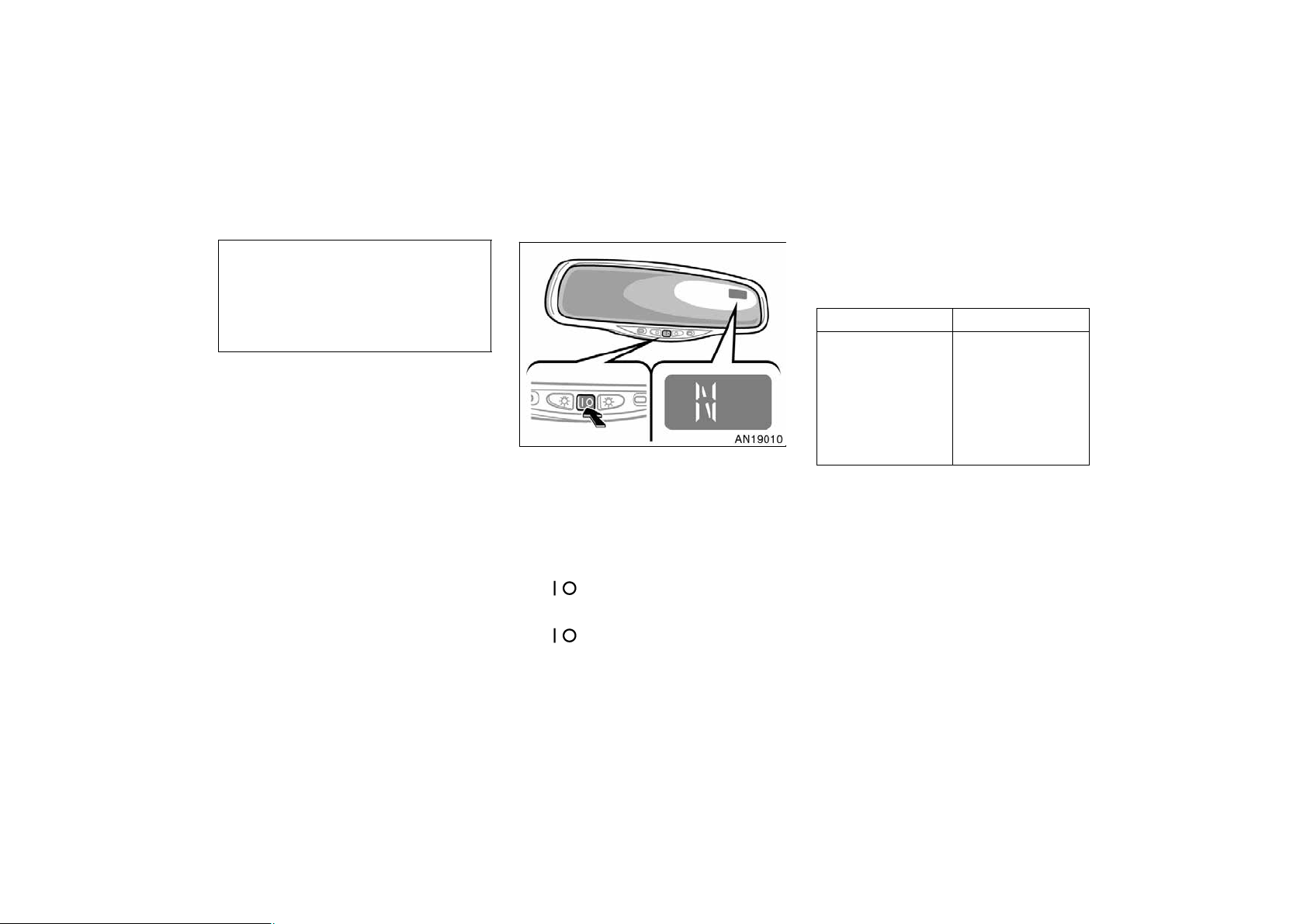
Compass
The direction is indicated on the inside
rear view mirror.
If the ignition switch was turned off with
the system on, the system will automatically turn back on when the ignition switch
is turned on.
To turn on the compass, push and hold
the “
on.
To turn off the compass, push and hold
the “
off.
” switch until the display turns
” switch until the display turns
The compass indicates the direction
that the vehicle is heading. In the
above case, it shows that the vehicle is
heading north.
Displays
N
NE
E
SE
S
SW
W
NW
The compass may not show the correct
direction in the following conditions:
Directions
North
Northeast
East
Southeast
South
Southwest
West
Northwest
D The vehicle is stopped immediately af-
ter turning.
D The compass does not adjust while the
vehicle is stopped.
D The ignition switch is turned off imme-
diately after turning.
D The vehicle is on an inclined surface.
157
2004 MATRIX from Oct. ’03 Prod. (OM12861U)
Page 12
D The vehicle is in a place where the
earth’s magnetic field is subject to interference by artificial magnetic fields
(underground parking, under a steel
tower, between buildings, roof parking,
near a crossing, near a large vehicle,
etc.).
D The vehicle is magnetized. (There is a
magnet or a metal object on or near
the inside rear view mirror.)
D The battery has been disconnected.
Your vehicle is out of the set zone. Refer
to the “CALIBRATING THE COMPASS” below to set the zone number.
The compass works to calibrate the direction automatically while the vehicle is in
motion, if deviation is small.
For additional precision or for complete
calibrating, see “CALIBRATING THE
COMPASS” below.
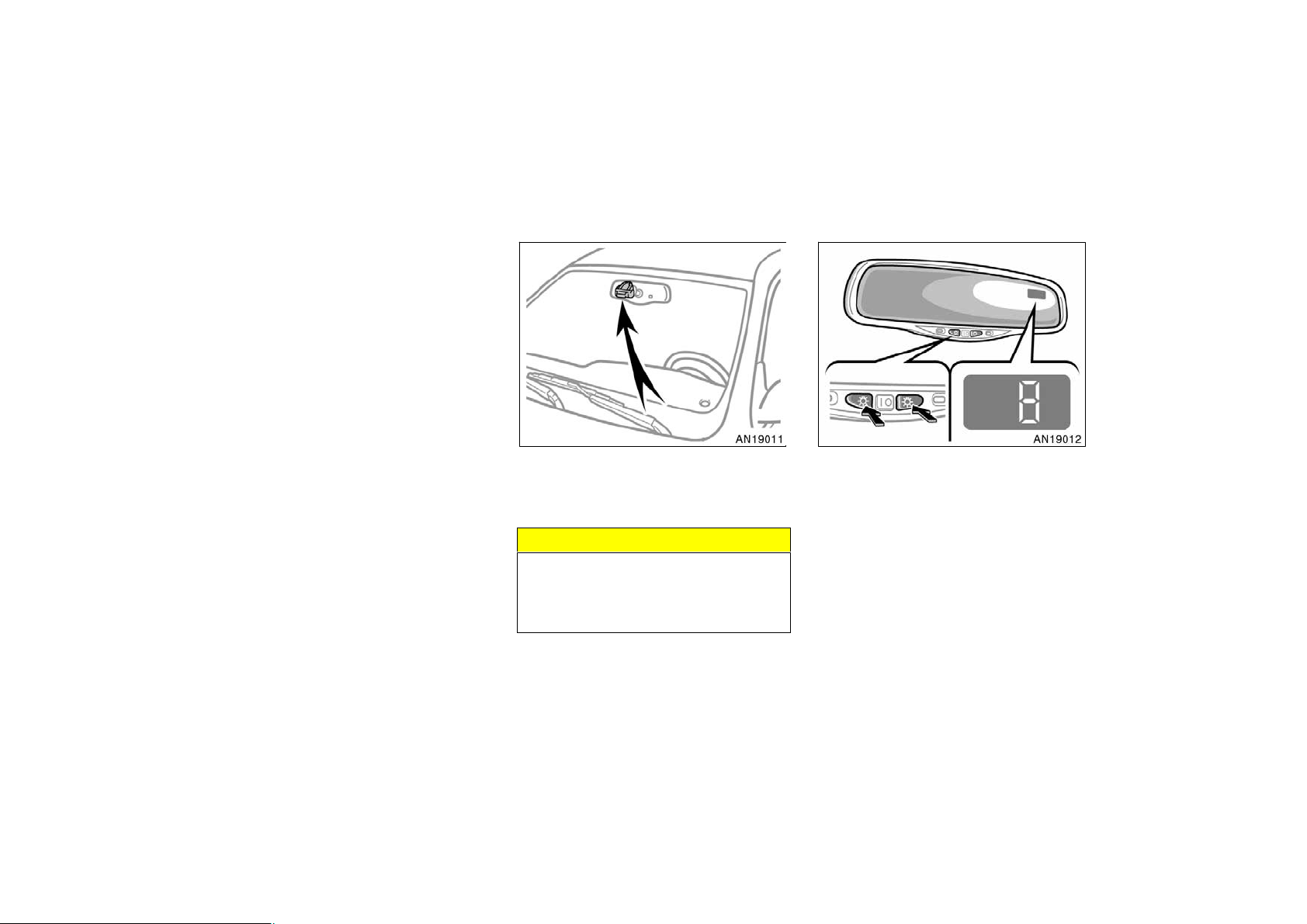
’04 MATRIX_U (L/O 0307)
Compass sensor
The compass sensor is in the inside
rear view mirror.
NOTICE
Do not put magnets or a metal object
on or near the inside rear view mirror
of the vehicle. Doing this may cause
malfunction of the compass sensor.
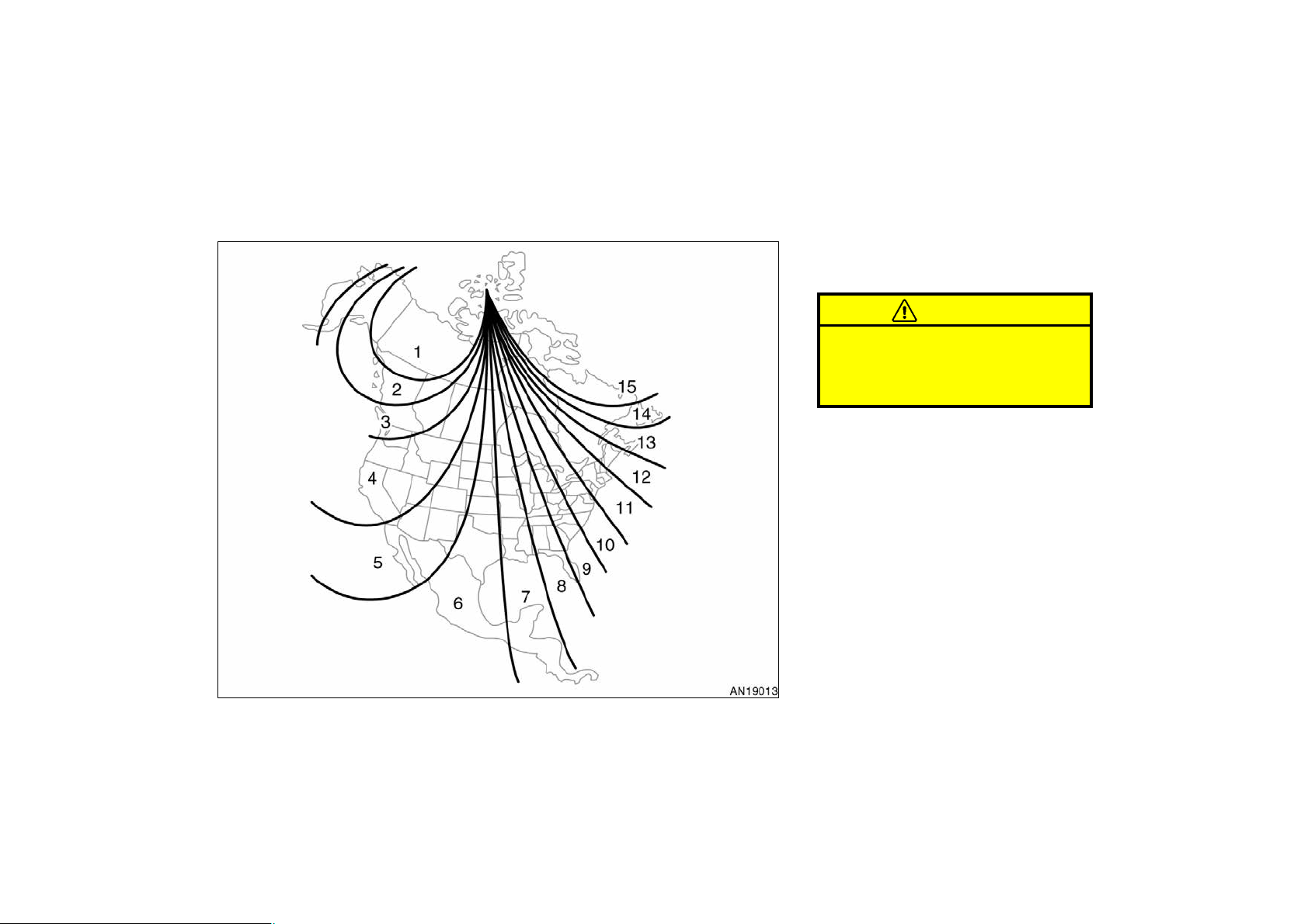
CALIBRATING THE COMPASS (deviation
calibration)
The direction display on the compass
deviates from the true direction determined by the earth’s magnetic field. The
angle of deviation varies according to the
geographic position of the vehicle.
To adjust this deviation, stop the vehicle,
then push and hold the both personal light
switches until the zone number appears
on the display. Then push the right side
or left side personal light switch, referring
to the following map to select the number
of the zone where the vehicle is.
158
2004 MATRIX from Oct. ’03 Prod. (OM12861U)
Page 13
’04 MATRIX_U (L/O 0307)
After calibration, leaving the system for
Hawaii: 5
Samoa: 5
Guam: 8
Saipan: 8
several seconds returns it to the compass
mode.
Do not adjust the display while the
vehicle is moving. Be sure to adjust
the display only when the vehicle is
stopped.
CAUTION
Zone number
159
2004 MATRIX from Oct. ’03 Prod. (OM12861U)
Page 14
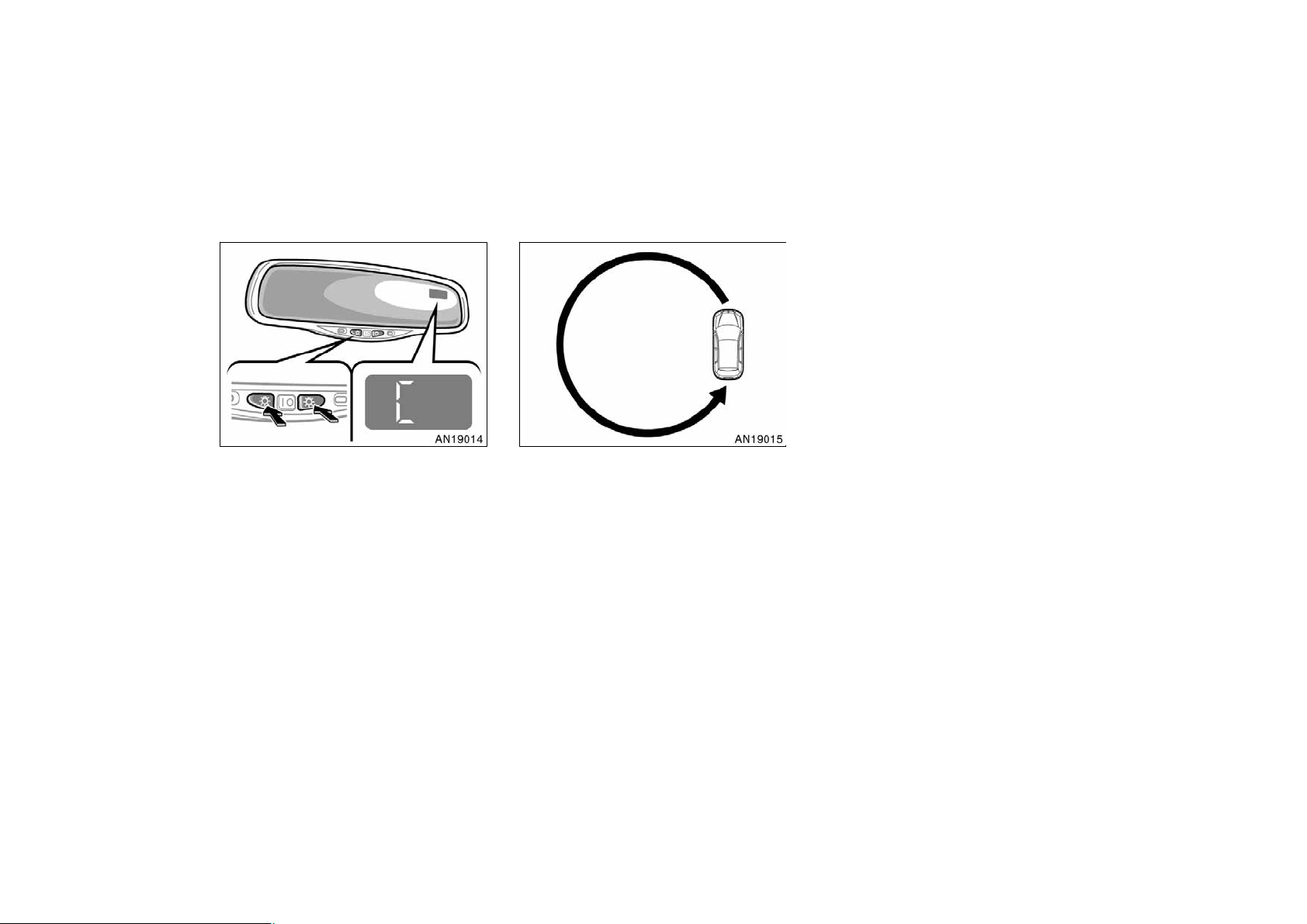
CALIBRATING THE COMPASS (circling
calibration)
Sometimes the direction display on the
compass may not change after a turn. To
rectify this, stop the vehicle and push and
hold the both personal light switches until
“C” appears on the display.
If “C” appears on the display because of
a drastic change in the magnetic field,
perform circling calibration.
’04 MATRIX_U (L/O 0307)
Drive the vehicle in a circle at 8 km/h (5
mph) or less. If there is not enough space
to drive in a circle, drive around the
block.
After driving 1 to 3 circles in the above
method, calibration is completed when the
direction is shown on the display.
If calibration cannot be performed because
of the magnetized vehicle etc., take your
vehicle to Toyota dealer.
Perform circling calibration just after
you have purchased your Toyota. And
then always perform circling calibration
after the battery has been removed, replaced or disconnected.
D Do not perform circling calibration of
the compass in a place where the
earth’s magnetic field is subject to interference by artificial magnetic fields
(underground parking, under a steel
tower, between buildings, roof parking,
near a crossing, near a large vehicle,
etc.).
D During calibration, do not operate elec-
tric systems (moon roof, power windows, etc.) as they may interfere with
the calibration.
160
2004 MATRIX from Oct. ’03 Prod. (OM12861U)
Page 15
CAUTION
D When doing the circling calibration,
be sure to secure a wide space,
and watch out for people and vehicles in the neighborhood. Do not
violate any local traffic rules while
performing circling calibration.
D Do not adjust the display while the
vehicle is moving. Be sure to adjust
the display only when the vehicle is
stopped.
’04 MATRIX_U (L/O 0307)
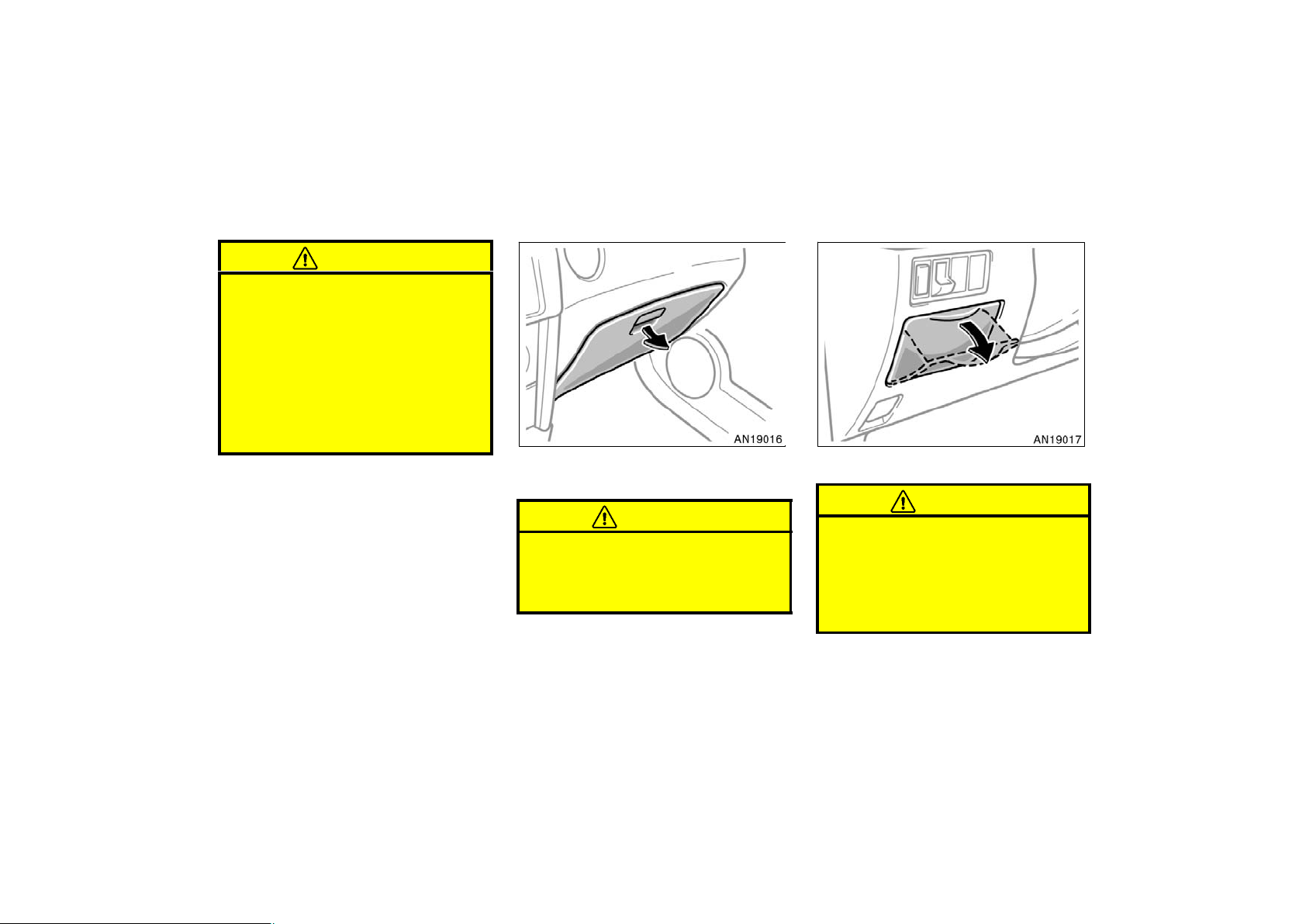
Glove box Auxiliary box (type A)
To open the glove box door, pull the
lever.
CAUTION
To reduce the chance of injury in
case of an accident or a sudden stop,
always keep the glove box door
closed while driving.
To use the box, pull on the handle.
CAUTION
D To reduce the chance of injury in
case of an accident or a sudden
stop, always keep the auxiliary box
closed while driving.
D Do not use this auxiliary box as an
ashtray.
161
2004 MATRIX from Oct. ’03 Prod. (OM12861U)
Page 16
’04 MATRIX_U (L/O 0307)
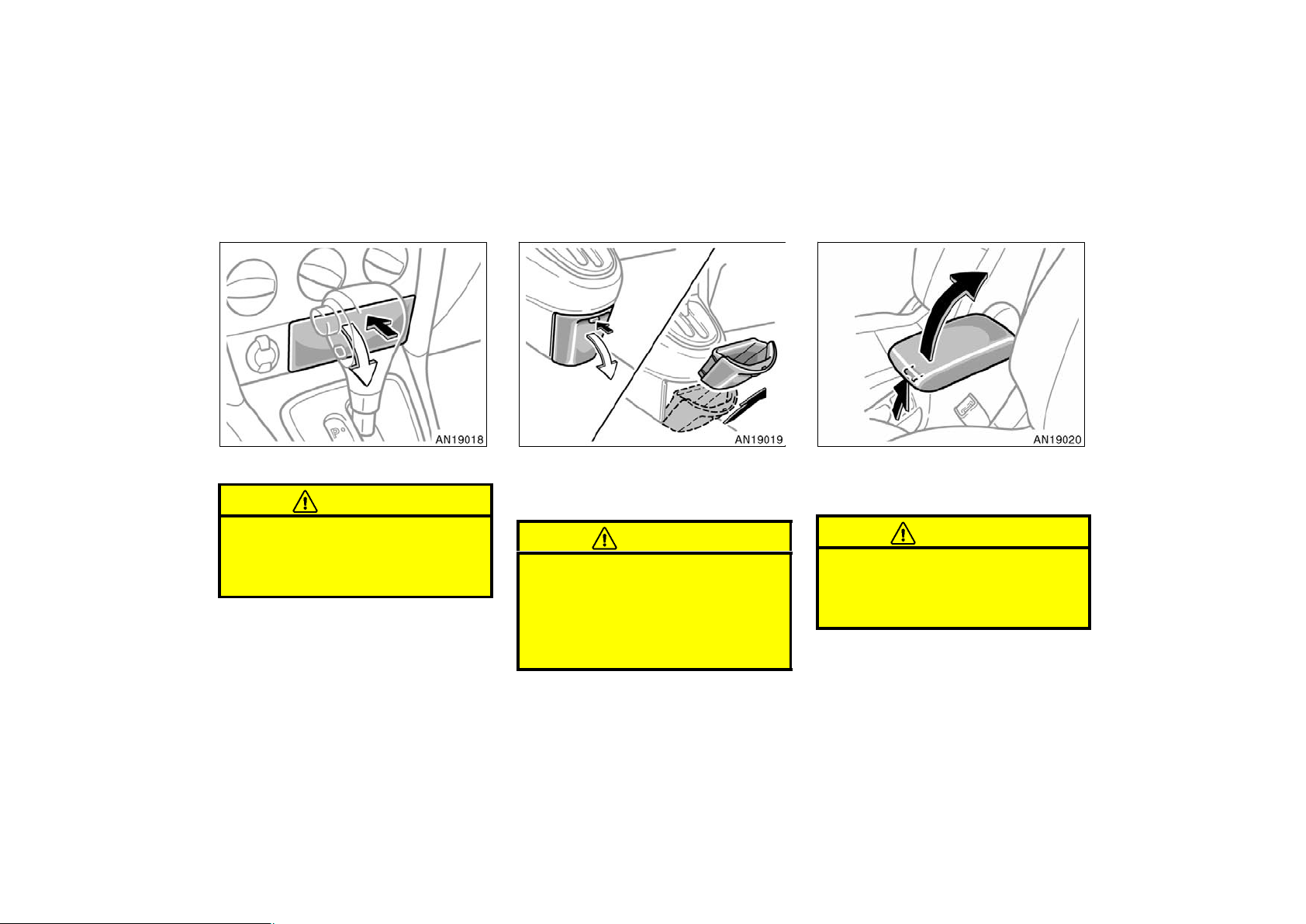
Auxiliary box (type B) Auxiliary box (type C) Rear console box (type A)
To use the box, push the lid.
CAUTION
To reduce the chance of injury in
case of an accident or a sudden stop,
always keep the auxiliary box closed
while driving.
162
To use the box, push the knob.
To remove the auxiliary box, open the box
and pull it up.
CAUTION
D To reduce the chance of injury in
case of an accident or a sudden
stop, always keep the auxiliary box
closed while driving.
D Do not use this auxiliary box as an
ashtray.
To access the rear console box, pull up
the lock release lever while raising the
rear console box lid.
CAUTION
To reduce the chance of injury in
case of an accident or a sudden stop,
always keep the console box closed
while driving.
2004 MATRIX from Oct. ’03 Prod. (OM12861U)
Page 17
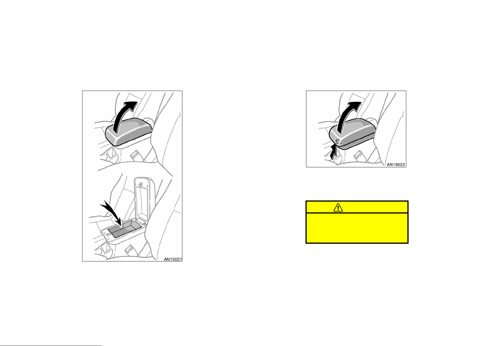
Rear console box (type B)
’04 MATRIX_U (L/O 0307)
UPPER TRAY
To access the upper tray, raise the console box lid without touching the lock
release lever.
CONSOLE BOX
To access the rear console box, pull up
the lock release lever while raising the
rear console box lid.
CAUTION
To reduce the chance of injury in
case of an accident or a sudden stop,
always keep the console box closed
while driving.
163
2004 MATRIX from Oct. ’03 Prod. (OM12861U)
Page 18
’04 MATRIX_U (L/O 0307)
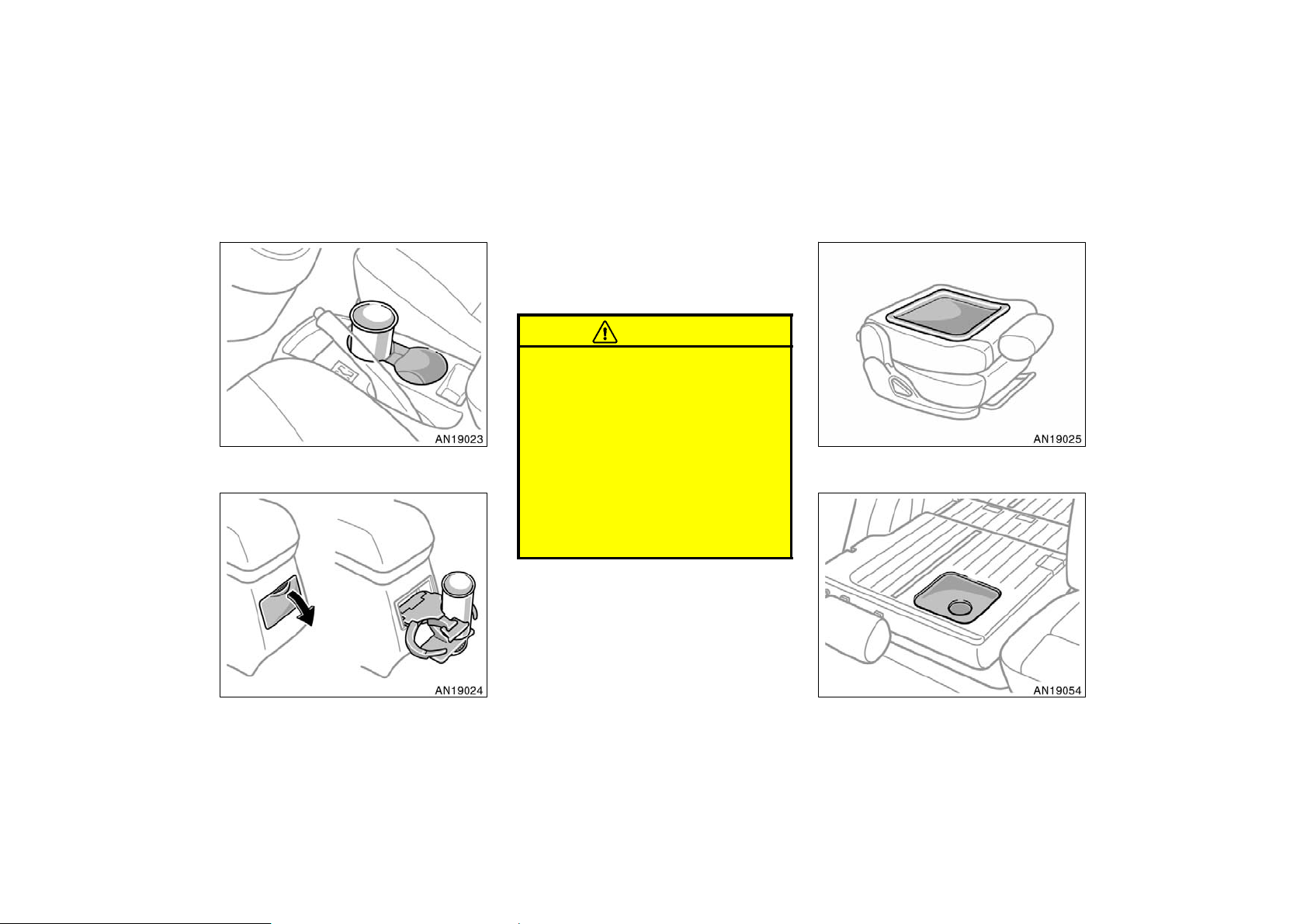
Cup holders Seatback tables
The cup holder is designed for holding
cups or drink−cans securely.
Rear cup holder—To use the holder, pull
it out.
CAUTION
D Do not place anything else other
than cups or drink−cans in the cup
holder, as such items may be
thrown about in the compartment
and possibly injure people in the
vehicle during sudden braking or in
Front
an accident.
Front passenger’s seatback
D Rear cup holder—To reduce the
chance of injury in case of an accident or sudden stop while driving,
keep the cup holder closed when it
is not in use.
Rear
164
Rear right side seatback
2004 MATRIX from Oct. ’03 Prod. (OM12861U)
Page 19
You can use the front passenger’s seatback and rear right side seatback as a
temporary table only when the vehicle
is stopped.
To use the seatback table, fold the seatback down. For detailed information, see
“—Fold−down front passenger’s seat” on
page 31 or “Fold−down rear seat” on page
32 in Section 1−3.
CAUTION
To avoid serious injury:
D Do not set up the seatback table
while the vehicle is moving.
D Do not sit on the seatback table.
’04 MATRIX_U (L/O 0307)
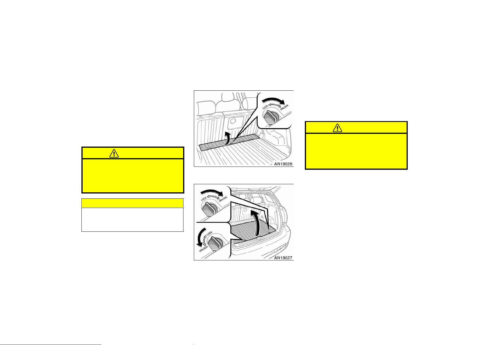
Luggage storage boxes
To open the luggage storage box, turn
the knobs to the “UNLOCK” position
and open the lid. To close the luggage
storage box, lower the lid and turn the
knobs to the “LOCK” position.
CAUTION
To reduce the chance of injury in
case of an accident or a sudden stop,
always keep the luggage storage
boxes closed and locked while driving.
Front
NOTICE
To prevent damage to the seat, avoid
putting heavy loads on the temporary
table.
Rear
165
2004 MATRIX from Oct. ’03 Prod. (OM12861U)
Page 20
’04 MATRIX_U (L/O 0307)
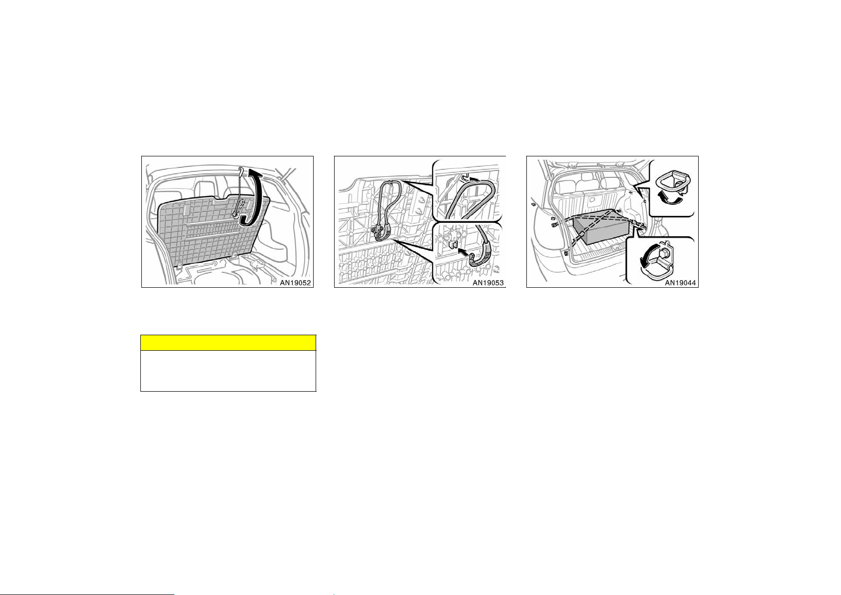
Tie−down hooks and tire
tie−down belts
Rear luggage storage box—
To keep the lid open, attach the hook as
shown above.
NOTICE
Do not close the back door with the
hook attached, or the hook may be
damaged.
166
Keep the hook stored in its original position as shown when it is not in use.
To secure your luggage, use the tie−
down hooks as shown above.
The tire tie−down belts are designed to
secure the flat tire. You can also use the
belts to secure your luggage. (To secure
the flat tire, see “—Stowing flat tire” on
page 225 in Section 4.)
See “—Stowage precautions” on page 192
in Section 2 for precautions when loading
luggage.
2004 MATRIX from Oct. ’03 Prod. (OM12861U)
Page 21
Luggage deck rails
’04 MATRIX_U (L/O 0307)
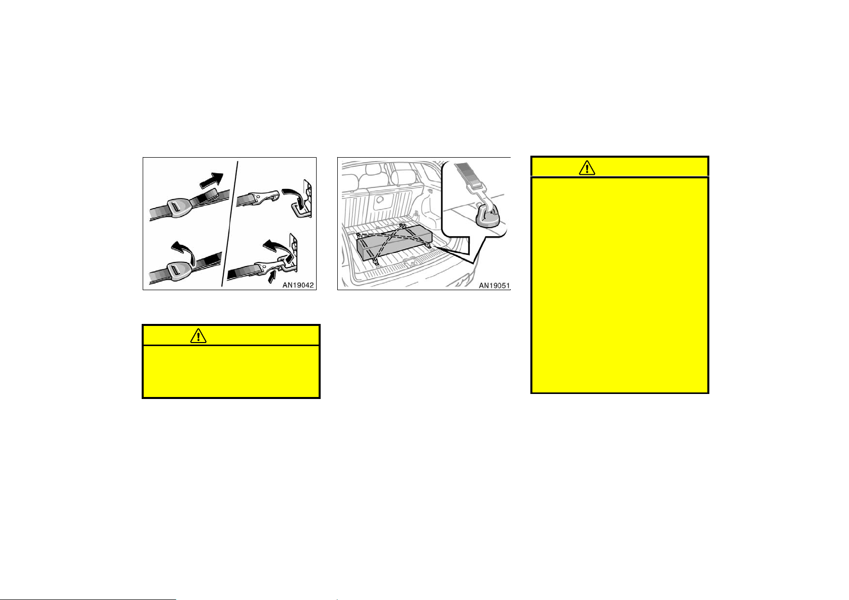
To tighten
To loosen
To use the tire tie−down belts, do as
shown in the illustration.
To hook
To unhook
CAUTION
To avoid personal injury, keep the tie−
down hooks retracted and the tire
tie−down belts stored in the luggage
storage box when not in use.
To use the luggage deck rails, you
must install genuine Toyota accessories
or their equivalent for the deck rails.
Follow the manufacturer’s instructions and
precautions when installing a genuine
Toyota accessory or equivalent.
See “—Stowage precautions” on page 192
in Section 2 for precautions when loading
luggage.
CAUTION
When you secure cargo with the luggage deck rails, be sure follow the
instructions below in order to avoid
the cargo coming loose:
D Do not place cargo exceeding 31 kg
(70 lb.) on the luggage deck rails.
D To prevent luggage or cargo from
sliding forward during braking,
make sure the deck rail accessories
such as tie−down hooks are secure-
ly attached on the deck rails.
D When the rear seats are folded
down, they are not locked into
place and may move. After driving
on rough roads or at high speeds,
cargo attached to the seat back
rails may have moved out of place.
Check the cargo and resecure if
necessary.
167
2004 MATRIX from Oct. ’03 Prod. (OM12861U)
Page 22
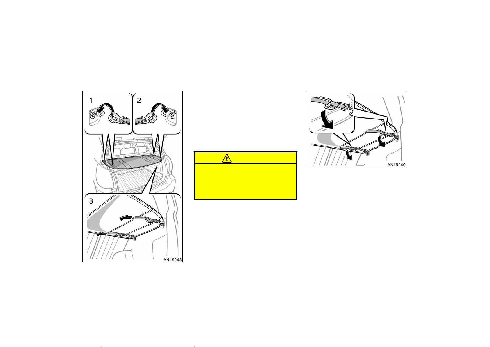
Luggage cover
’04 MATRIX_U (L/O 0307)
To use the luggage cover:
1. Attach the left side hooks of the luggage cover to the left side upper
tie−down hooks.
2. Attach the right side hooks of the
luggage cover to the right side upper tie−down hooks.
3. Pull the belt ends of the right side
hooks to secure the luggage cover.
CAUTION
Do not place anything on the luggage
cover. Such items may be thrown
about and possibly injure people in
the vehicle during sudden braking or
an accident.
To remove the luggage cover, loosen
the right side belts of the hooks as
shown above. Then remove the hooks
from tie−down hooks.
When you remove the luggage cover, fold
up and store it in the luggage storage
box.
168
2004 MATRIX from Oct. ’03 Prod. (OM12861U)
Page 23
Floor mat
’04 MATRIX_U (L/O 0307)
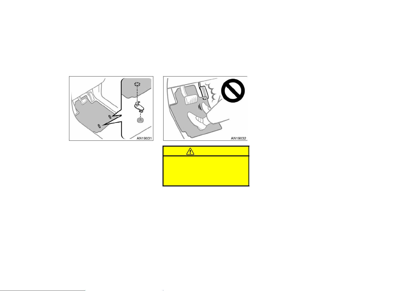
Use a floor mat of the correct size.
If the floor carpet and floor mat have two
holes, then it is designed for use with two
locking clips. Fix the floor mat with locking clips into the holes in the floor carpet.
CAUTION
Make sure the floor mat is properly
placed on the floor carpet. If the floor
mat slips and interferes with the
movement of the pedals during driving, it may cause an accident.
169
2004 MATRIX from Oct. ’03 Prod. (OM12861U)
Page 24

’04 MATRIX_U (L/O 0307)
170
2004 MATRIX from Oct. ’03 Prod. (OM12861U)
Page 25

’04 MATRIX_U (L/O 0307)
SECTION 1− 2
OPERATION OF INSTRUMENTS AND
CONTROLS
Keys and Doors
Keys 8. . . . . . . . . . . . . . . . . . . . . . . . . . . . . . . . . . . . . . . . . . . . . . . . . . . . . . . .
Side doors 8. . . . . . . . . . . . . . . . . . . . . . . . . . . . . . . . . . . . . . . . . . . . . . . . . . .
Power windows 15. . . . . . . . . . . . . . . . . . . . . . . . . . . . . . . . . . . . . . . . . . . . . .
Back door 17. . . . . . . . . . . . . . . . . . . . . . . . . . . . . . . . . . . . . . . . . . . . . . . . . . .
Glass hatch 18. . . . . . . . . . . . . . . . . . . . . . . . . . . . . . . . . . . . . . . . . . . . . . . . .
Toyota vehicle intrusion protection system (TVIP) 20. . . . . . . . . . . . . . .
Hood 21. . . . . . . . . . . . . . . . . . . . . . . . . . . . . . . . . . . . . . . . . . . . . . . . . . . . . . .
Fuel tank cap 23. . . . . . . . . . . . . . . . . . . . . . . . . . . . . . . . . . . . . . . . . . . . . . .
Electric moon roof 24. . . . . . . . . . . . . . . . . . . . . . . . . . . . . . . . . . . . . . . . . . .
2004 MATRIX from Oct. ’03 Prod. (OM12861U)
7
Page 26
’04 MATRIX_U (L/O 0307)
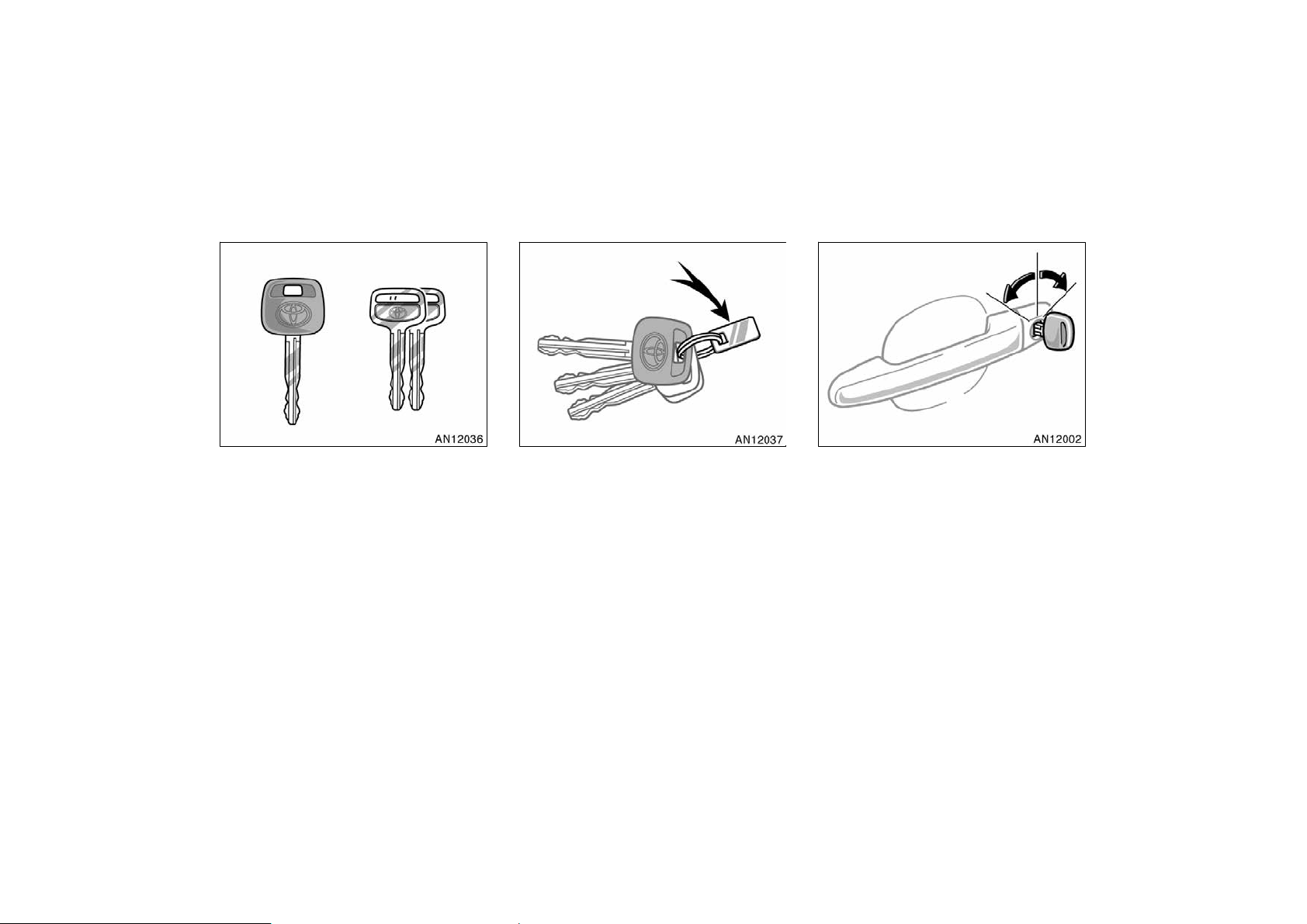
Keys Side doors—
These keys work in every lock.
Since the side doors can be locked without a key, you should always carry a
spare key in case you accidentally lock
your keys inside the vehicle.
8
KEY NUMBER PLATE
Your key number is shown on the plate.
Keep the plate in a safe place such as
your wallet, not in the vehicle.
If you should lose your keys or if you
need additional keys, duplicates can be
made by a Toyota dealer using the key
number.
We recommend writing down the key number and storing it in a safe place.
LOCKING AND UNLOCKING WITH KEY
Insert the key into the keyhole and turn
it.
To lock: Turn the key forward.
To unlock: Turn the key backward.
Vehicles with power door lock system—
All the side doors and back door lock and
unlock simultaneously with either front
door. In the driver’s door lock, turning the
key once will unlock the driver’s door and
twice in succession will unlock all the side
doors and back door simultaneously.
2004 MATRIX from Oct. ’03 Prod. (OM12861U)
Page 27
’04 MATRIX_U (L/O 0307)
When the interior light dial is in the door
position, and all the side doors and back
door are unlocked simultaneously with a
key or wireless remote control transmitter,
the interior lights come on for about 15
seconds and then fade out, even if the
door is not opened. (For further information, see “Interior/instrument panel light
control” on page 81 in Section 1−5.)
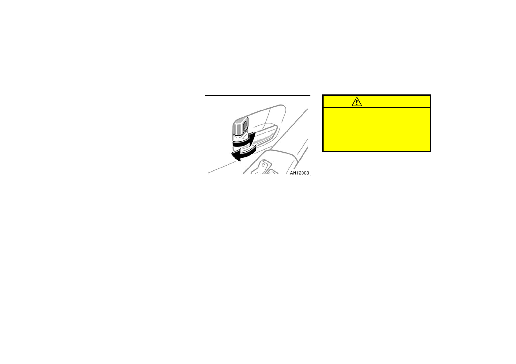
LOCKING AND UNLOCKING WITH
INSIDE LOCK KNOB
Move the lock knob.
To lock: Push the knob forward.
To unlock: Pull the knob backward.
The front doors can be opened by pulling
the inside handle even if the lock knobs
are in the locked position.
CAUTION
Do not pull the inside handle of the
front doors while driving. The doors
will open and an accident may occur.
Toyota strongly recommends that all
children be placed in the rear seat of
the vehicle.
Closing the door with the lock knob in the
lock position will also lock the door. Be
careful not to lock your keys in the vehicle.
Vehicles with power door lock system—
Doors cannot be locked when either front
door is open and the key is in the ignition.
2004 MATRIX from Oct. ’03 Prod. (OM12861U)
9
Page 28
’04 MATRIX_U (L/O 0307)
Driver’s side
Passenger’s side
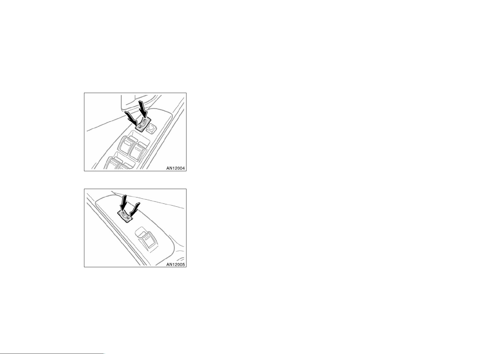
LOCKING AND UNLOCKING WITH
POWER DOOR LOCK SWITCH
Push the switch.
To lock: Push the switch down on the
front side.
To unlock: Push the switch down on the
rear side.
Operating the switch simultaneously locks
or unlocks all the side doors and back
door.
If you do either of the followings, no side
door or back door can be unlocked with
the power door lock switch.
D Lock all the side doors and back door
with the key or wireless remote control
transmitter when all the side doors and
back door are closed.
D Open the driver’s door or front passen-
ger’s door and move the inside lock
knobs of both front doors to the lock
position, then close the front doors.
The power door lock switch can be reset
in the following ways.
D Turn the ignition key to “ON”.
D Unlock all the side doors and back
door with the key or wireless remote
control transmitter.
D Unlock the driver’s door or front pas-
senger’s door with the inside lock
knob, and then unlock all the side
doors and back door with the power
door lock switch.
10
2004 MATRIX from Oct. ’03 Prod. (OM12861U)
Page 29
’04 MATRIX_U (L/O 0307)
CAUTION
Before driving, be sure that the doors
are closed and locked, especially
when small children are in the vehicle. Along with the proper use of
seat belts, locking the doors helps
prevent the driver and passengers
from being thrown out from the vehicle during an accident. It also helps
prevent the doors from being opened
unintentionally.
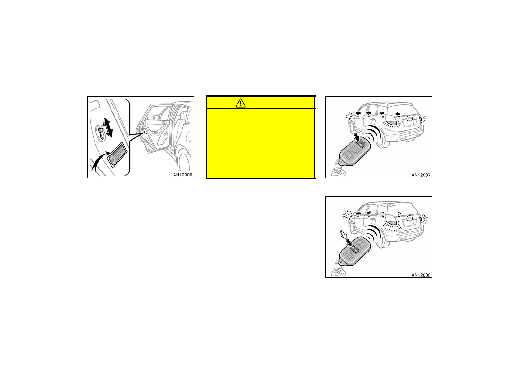
—Wireless remote control
REAR DOOR CHILD−PROTECTORS
Move the lock lever to the “LOCK”
position as shown on the label.
This feature allows you to lock a rear
door so it can be opened from the outside
only, not from inside. We recommend using this feature whenever small children
are in the vehicle.
Locking operation
Unlocking operation
11
2004 MATRIX from Oct. ’03 Prod. (OM12861U)
Page 30
’04 MATRIX_U (L/O 0307)
The wireless remote control system is
designed to lock or unlock all the side
doors and back door, open the glass
hatch or activate the “PANIC” mode
from a distance within approximately 1
m (3 ft.) of the vehicle.
LOCKING AND UNLOCKING THE SIDE
DOORS AND BACK DOOR
To lock and unlock all the side doors
and back door, push the switches of
the transmitter slowly and securely.
To lock: Push the “LOCK” switch. All the
side doors and back door are locked simultaneously. At this time, turn signal
lights flash once.
Check to see that all the side doors and
back door are securely locked.
If any of side doors or back door is not
securely closed, or if the key is in the
ignition switch, locking cannot be performed by the “LOCK” switch.
To unlock: Push the “UNLOCK” switch
once to unlock the driver’s door alone.
Pushing the switch twice within 3 seconds
unlocks all the side doors and back door
simultaneously. At this time, turn signal
lights flash twice.
When the interior light dial is in the door
position, and all the side doors and back
door are unlocked simultaneously with a
wireless remote control transmitter, the interior lights come on for about 15 seconds
and then fade out, even if the door is not
opened. (For further information, see “Interior/instrument panel light control” on page
81 in Section 1−5.)
You have 30 seconds to open a door after
using the wireless remote unlock feature.
If a door is not opened by then, all the
side doors and back door will be automatically locked again.
If the “LOCK” or “UNLOCK” switch is kept
pressed in, the locking or unlocking operation is not repeated. Release the switch
and then push again.
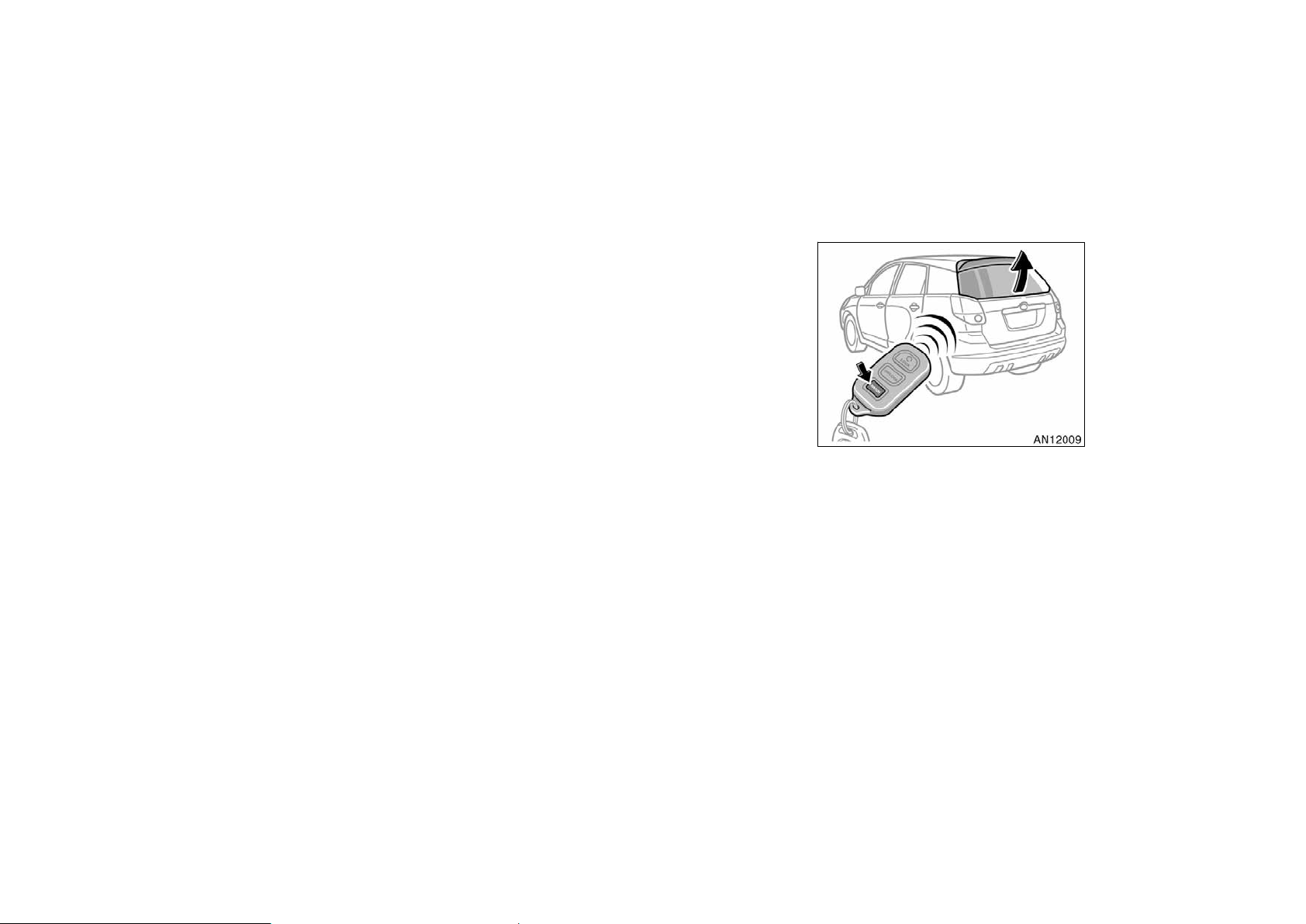
OPENING THE GLASS HATCH
To open the glass hatch, push the
“HATCH” switch of the transmitter for
1 second.
If the ignition key is in the “ON” position,
the glass hatch cannot be opened by the
“HATCH” switch.
See “Glass hatch” on page 18 in this
Section.
12
2004 MATRIX from Oct. ’03 Prod. (OM12861U)
Page 31

’04 MATRIX_U (L/O 0307)
“PANIC” SWITCH
Pushing the “PANIC” switch blows the
horn intermittently and flashes the
headlights, turn signal lights and interior lights.
The “PANIC” switch is used to deter vehicle theft when you witness anyone attempting to break into or damage your
vehicle.
The alarm will last for one minute. To stop
alarm midway, do the following:
D Push the “PANIC” switch once again.
D Unlock any of side doors, back door or
glass hatch with the key or wireless
remote control transmitter.
D Turn the ignition key from the “LOCK”
to “ON” position.
The “PANIC” mode does not work when
the ignition key is in the “ON” position.
WIRELESS REMOTE CONTROL
TRANSMITTER
The wireless remote control transmitter is
an electronic component. Observe the following instructions in order not to cause
damage to the transmitter.
D Do not leave the transmitter on places
where the temperature becomes high
such as on the dashboard.
D Do not disassemble it.
D Avoid knocking it hard against other
objects or dropping it.
D Avoid putting it in water.
You can use up to 4 wireless remote control transmitters for the same vehicle.
Contact your Toyota dealer for detailed
information.
If the wireless remote control transmitter
does not actuate the doors or alarm, or
operate from a normal distance:
D Check for closeness to a radio trans-
mitter such as a radio station or an
airport which can interfere with normal
operation of the transmitter.
D The battery may have been consumed.
Check the battery in the transmitter. To
replace the battery, see “REPLACING
TRANSMITTER BATTERY”.
If you lose your transmitter, contact your
Toyota dealer as soon as possible to
avoid the possibility of theft, or an accident. (See “If you lose your wireless remote control transmitter” on page 233 in
Section 4.)
MODEL/FCC ID: GQ43VT27R
CAN: 1470 104 105A
MADE IN U.S.A.
This complies with Part 15 of the FCC
rules. Operation is subject to the following two conditions:
(1) This device may not cause harmful
interference, and (2) this device must
accept any interference received, including interference that may cause undesired operation.
13
2004 MATRIX from Oct. ’03 Prod. (OM12861U)
Page 32

REPLACING TRANSMITTER BATTERY
For replacement, use a CR2032 lithium
battery or equivalent.
CAUTION
Special care should be taken to prevent small children from swallowing
the removed transmitter battery or
components.
NOTICE
z During replacing the transmitter
battery, do not push the “LOCK”,
“UNLOCK” and “HATCH” switches
many times.
z When replacing the transmitter bat-
tery, be careful not to lose the components.
z Replace only with the same or
equivalent type recommended by a
Toyota dealer.
z Dispose of used batteries according
to the local laws.
’04 MATRIX_U (L/O 0307)
1. Using a coin or equivalent, open the
transmitter case.
2. Remove the discharged transmitter battery.
NOTICE
Do not bend the terminals.
Replace the transmitter battery by following these procedures:
14
2004 MATRIX from Oct. ’03 Prod. (OM12861U)
Page 33

’04 MATRIX_U (L/O 0307)
z Be careful not to bend the electrode
of the transmitter battery insertion
and that dust or oils do not adhere
to the transmitter case.
z Close the transmitter case securely.
After replacing the battery, check that the
transmitter operates properly. If the transmitter still does not operate properly, contact your Toyota dealer.
Power windows
3. Put a new transmitter battery with positive (+) side up.
Close the transmitter case securely.
NOTICE
z Make sure the positive side and
negative side of the transmitter battery are faced correctly.
z Do not replace the battery with wet
hands. Water may cause unexpected
rust.
z Do not touch or move any compo-
nents inside of the transmitter, or
it may interfere with proper operation.
The windows can be operated with the
switch on each side door.
The power windows work when the ignition
switch is in the “ON” position.
OPERATING THE DRIVER’S WINDOW
Use the switch on the driver’s door.
Normal operation: The window moves as
long as you hold the switch.
To open: Lightly push down the switch.
To close: Pull up the switch.
15
2004 MATRIX from Oct. ’03 Prod. (OM12861U)
Page 34

Window lock
switch
’04 MATRIX_U (L/O 0307)
Automatic operation (to open only):
Push the switch completely down and then
release it. The window will fully open. To
stop the window partway, lightly pull the
switch up and then release it.
16
OPERATING THE PASSENGERS’
WINDOWS
Use the switch on each passenger’s
door or the switches on the driver’s
door that control each passenger’s window.
The window moves as long as you hold
the switch.
To open: Push down the switch.
To close: Pull up the switch.
If you push in the window lock switch on
the driver’s door, the passengers’ windows
cannot be operated.
2004 MATRIX from Oct. ’03 Prod. (OM12861U)
Page 35

’04 MATRIX_U (L/O 0307)
Back door
CAUTION
To avoid serious personal injury, you
must do the following.
D Before you close the power win-
dows, always make sure there is
nobody around the power windows.
You must also make sure the
heads, hands and other parts of the
bodies of all occupants are kept
completely inside the vehicle. If
someone’s neck, head or hands get
caught in a closing window, it
could result in a serious injury.
When anyone closes the power windows, make sure he or she operates the windows safely.
D When small children are in the ve-
hicle, never let them use the power
window switches without supervision. Use the window lock switch to
prevent them from making unexpected use of the switches.
D Be sure to remove the ignition key
when you leave your vehicle.
D Never leave anyone (particularly a
small child) alone in your vehicle,
especially with the ignition key still
inserted. Otherwise, he/she could
use the power window switches and
get trapped in a window. Unattended person (particularly a small
child) can be involved in a serious
accident.
LOCKING AND UNLOCKING WITH KEY
Insert the key into the keyhole and turn
it.
To lock: Turn the key clockwise.
If you turn the key fully clockwise, the
glass hatch will open. (See “Glass hatch”
on page 18 in this Section.)
To unlock: Turn the key counterclockwise.
To open the back door, pull the lock release lever.
Operating the power door lock switch or
wireless remote control transmitter simultaneously locks or unlocks the back door.
(See “Side doors” on page 8 in this Section.)
17
2004 MATRIX from Oct. ’03 Prod. (OM12861U)
Page 36

When closing the back door, the inside
handle can be used to make the reach
easier.
To close the back door, lower it and press
down on it. After closing the back door,
try pulling it up to make sure it is securely closed.
See “—Stowage precautions” on page 192
in Section 2 for precautions when loading
luggage.
’04 MATRIX_U (L/O 0307)
CAUTION
Keep the back door and glass hatch
closed while driving. This not only
keeps the luggage from being thrown
out but also prevents exhaust gases
from entering the vehicle.
NOTICE
To prevent damage to the back door
and glass hatch dampers, do not apply any force, paint or let any other
foreign matter on them.
Glass hatch
OPENING THE GLASS HATCH WITH
THE KEY
Insert the key into the keyhole and turn
it fully clockwise (one step further than
the back door locking position).
The glass hatch can be opened with the
wireless remote control transmitter. See
“—Wireless remote control” on page 11 in
this Section.
18
2004 MATRIX from Oct. ’03 Prod. (OM12861U)
Page 37

’04 MATRIX_U (L/O 0307)
OPENING THE GLASS HATCH WITH
THE GLASS HATCH OPENER SWITCH
Push the glass hatch opener switch
when the vehicle is stopped.
CAUTION
Do not open the glass hatch while
the vehicle is moving.
If you do either of the followings, the
glass hatch cannot be opened with the
glass hatch opener switch.
D Lock all the side doors and back door
with the key or wireless remote control
transmitter when the front doors are
closed.
D Open the driver’s door or front passen-
ger’s door and move the inside lock
knobs of both front doors to the lock
position, then close the front doors.
The glass hatch opener switch can be
reset in the following ways.
D Turn the ignition key to “ON”.
D Unlock all the doors with the key or
wireless remote control transmitter.
D Unlock the driver’s door or front pas-
senger’s door with the inside lock
knob, and then unlock all the doors
with the power door lock switch.
CLOSING THE GLASS HATCH
Lower the glass hatch and push the
lower center of it until it is locked.
When you open the back door with the
glass hatch opened, the glass hatch will
be closed. After closing the back door,
you should check the glass hatch fully
closed.
See “—Stowage precautions” on page 192
in Section 2 for precautions when loading
luggage.
CAUTION
Keep the back door and glass hatch
closed while driving. This not only
keeps the luggage from being thrown
out but also prevents exhaust gases
from entering the vehicle.
NOTICE
To prevent damage to the back door
and glass hatch dampers, do not apply any force, paint or let any other
foreign matter on them.
19
2004 MATRIX from Oct. ’03 Prod. (OM12861U)
Page 38

Toyota vehicle intrusion
protection system (TVIP)
TVIP is a theft deterrent system. If
someone attempts to damage or break
into your vehicle, the system sounds
the alarm while flashing the lights.
’04 MATRIX_U (L/O 0307)
SETTING THE SYSTEM
You can set the system as follows.
1. Remove the key from the ignition
switch.
2. Have all passengers get out of the
vehicle.
3. Close all the side doors, back door and
glass hatch securely.
4. Lock all the side doors and back door
with the key or wireless remote control
transmitter. At this time, the TVIP indicator light comes on.
The system will be set in 30 seconds.
When the system is set, the indicator
light will start to flash.
5. Make sure that the indicator light
flashes. Then you may leave the vehicle.
Never leave anyone in the vehicle when
you set the system because unlocking
from the inside activates the alarm.
Activating the alarm
If the system detects a threat to the
vehicle, it sounds the alarm for one
minute while flashing headlights and
turn signal lights. Also, the interior
lights turn on when the interior light
dial is in the door position.
The system detects a threat under any of
the following conditions:
D Either of the front doors is unlocked by
means other than the key or wireless
remote control transmitter.
If the key is not in the ignition switch,
all the side doors and back door will
be automatically locked again.
D Any of the side doors, back door or
glass hatch are forcibly opened.
The alarm will activate when the back
door is unlocked with a key. Cancel the
system before unlocking the back door.
20
2004 MATRIX from Oct. ’03 Prod. (OM12861U)
Page 39

D The side windows are tapped or bro-
ken.
D The battery terminal is disconnected
and then reconnected.
D The ignition is hotwired.
After one minute, the alarm automatically
stops and the indicator light starts flashing
again.
Reactivating the alarm
Once set, until you cancel the system, the
system automatically resets the alarm after the alarm has stopped.
The alarm will activate again under the
same circumstances described in “Activating the alarm”.
Stopping the alarm
You can stop the alarm in either of the
following ways:
D Unlock any of the side doors with the
key or wireless remote control transmitter.
D Place the ignition switch in the “ON”
position.
’04 MATRIX_U (L/O 0307)
CANCELLING THE SYSTEM
You can cancel the system as described
in “Stopping the alarm”.
If you cancel the system by unlocking any
of the side doors but no door is opened
within 30 seconds, all the side doors and
back door lock automatically and the system will be set again.
TESTING THE SYSTEM
You can check the system operation as
follows.
1. Open all the windows.
2. Set the system as described in
“SETTING THE SYSTEM”.
3. Unlock the driver’s door with the inside
lock knob. The system should activate
and the alarm should sound.
4. Stop the alarm as described in “Stopping the alarm”.
5. Repeat steps 2 to 4 for the other
doors. (For rear side doors, unlock and
then open the doors in step 3.)
If the system does not work properly,
have it checked by your Toyota dealer.
Hood
To open the hood:
1. Pull the hood lock release lever. The
hood will spring up slightly.
CAUTION
Before driving, be sure that the hood
is closed and securely locked. Otherwise, the hood may open unexpectedly while driving and an accident may
occur.
21
2004 MATRIX from Oct. ’03 Prod. (OM12861U)
Page 40

2. In front of the vehicle, pull up the
auxiliary catch lever and lift the
hood.
’04 MATRIX_U (L/O 0307)
3. Hold the hood open by inserting the
support rod into the slot.
To insert the support rod into the slot,
move it straight up. If it is moved to the
side or toward the inside of the vehicle,
it may become detached.
Before closing the hood, check to see that
you have not forgotten any tools, rags,
etc. and return the support rod to its
clip—this prevents rattles. Then lower the
hood and make sure it locks into place.
If necessary, press down gently on the
front edge to lock it.
CAUTION
After inserting the support rod into
the slot, make sure the rod supports
the hood securely from falling down
on to your head or body.
NOTICE
Be sure to return the support rod to
its clip before closing the hood. Closing the hood with the support rod up
could cause the hood to bend.
22
2004 MATRIX from Oct. ’03 Prod. (OM12861U)
Page 41

Fuel tank cap
’04 MATRIX_U (L/O 0307)
This indicates that the fuel filler door
is on the left side of your vehicle.
1. To open the fuel filler door, pull the
lever up.
When refueling, turn off the engine.
CAUTION
D Do not smoke, cause sparks or al-
low open flames when refueling.
The fumes are flammable.
D When opening the cap, do not re-
move the cap quickly. In hot weather, fuel under pressure could cause
injury by spraying out of the filler
neck if the cap is suddenly removed.
2. To remove the fuel tank cap, turn
the cap slowly counterclockwise,
then pause slightly before removing
it. After removing the cap, hang it
on the cap hanger.
It is not unusual to hear a slight swoosh
when the cap is opened. When installing,
turn the cap clockwise till you hear a
click.
If the cap is not tightened securely, the
malfunction indicator lamp comes on.
Make sure the cap is tightened securely.
The indicator lamp goes off after driving
several times. If the indicator lamp does
not go off, contact your Toyota dealer as
soon as possible.
23
2004 MATRIX from Oct. ’03 Prod. (OM12861U)
Page 42

CAUTION
D Make sure the cap is installed se-
curely to prevent fuel spillage in
the event of an accident.
D Use only a genuine Toyota fuel tank
cap for replacement. It is designed
to regulate fuel tank pressure.
Electric moon roof
Sliding operation
’04 MATRIX_U (L/O 0307)
To operate the moon roof, use the
switch beside the personal light.
The key must be in the “ON” position.
Sun shade operation—
The sun shade can be opened or closed
by hand.
Sliding operation—
To open: Push the switch on the rear
side.
The sun shade will be opened together
with the roof.
To close: Push the switch on the front
side.
As a precaution when closing, the roof
stops at the half closed position before
fully closing. Therefore, release the switch
and then push it again to close it completely.
Tilting operation—
To tilt up: Push the switch on the “UP”
side.
To lower: Push the switch on the opposite
side of the “UP” side.
24
Tilting operation
2004 MATRIX from Oct. ’03 Prod. (OM12861U)
Page 43

’04 MATRIX_U (L/O 0307)
You may stop the moon roof at any desired position. The roof will move while
the switch is being pushed and stop when
released except to slide open.
CAUTION
To avoid serious personal injury, you
must do the following.
D While the vehicle is moving, always
keep the heads, hands and other
parts of the bodies of all occupants
away from the roof opening. Otherwise, they could be seriously injured if the vehicle stops suddenly
or if the vehicle is involved in an
accident.
D Before you close the moon roof,
always make sure there is nobody
around the moon roof. You must
also make sure nobody places his
or her head, hands and other parts
of the body in the roof opening. If
someone’s neck, head or hands get
caught in the closing roof, it could
result in a serious injury. When
anyone closes the moon roof, first
make sure it is safe to do so.
D Be sure to remove the ignition key
when you leave your vehicle.
D Never leave anyone (particularly a
small child) alone in your vehicle,
especially with the ignition key still
inserted. Otherwise, he/she could
use the moon roof switches and get
trapped in the roof opening. Unattended person (particularly a small
child) can be involved in a serious
accident.
D Never sit on top of the vehicle
around the roof opening.
25
2004 MATRIX from Oct. ’03 Prod. (OM12861U)
Page 44

’04 MATRIX_U (L/O 0307)
26
2004 MATRIX from Oct. ’03 Prod. (OM12861U)
Page 45

’04 MATRIX_U (L/O 0307)
SECTION 1− 3
OPERATION OF INSTRUMENTS AND
CONTROLS
Occupant restraint systems
Seats 28. . . . . . . . . . . . . . . . . . . . . . . . . . . . . . . . . . . . . . . . . . . . . . . . . . . . . .
Front seats 28. . . . . . . . . . . . . . . . . . . . . . . . . . . . . . . . . . . . . . . . . . . . . . . . .
Fold−down rear seat 32. . . . . . . . . . . . . . . . . . . . . . . . . . . . . . . . . . . . . . . . .
Head restraints 33. . . . . . . . . . . . . . . . . . . . . . . . . . . . . . . . . . . . . . . . . . . . . .
Seat belts 34. . . . . . . . . . . . . . . . . . . . . . . . . . . . . . . . . . . . . . . . . . . . . . . . . . .
SRS driver airbag and front passenger airbag 42. . . . . . . . . . . . . . . . . . .
SRS side airbags 49. . . . . . . . . . . . . . . . . . . . . . . . . . . . . . . . . . . . . . . . . . . .
Child restraint 54. . . . . . . . . . . . . . . . . . . . . . . . . . . . . . . . . . . . . . . . . . . . . . .
27
2004 MATRIX from Oct. ’03 Prod. (OM12861U)
Page 46

Seats
While the vehicle is being driven, all vehicle occupants should have the seatback
upright, sit well back in the seat and properly wear the seat belts provided.
CAUTION
D Do not drive the vehicle unless the
occupants are properly seated. Do
not allow any passengers to sit on
top of a folded−down seatback, or
in the luggage compartment or cargo area. Persons not properly
seated and/or not properly restrained by seat belts can be severely injured in the event of emergency braking or a collision.
D During driving, do not allow any
passengers to stand up or move
around between seats. Otherwise,
severe injuries can occur in the
event of emergency braking or a
collision.
’04 MATRIX_U (L/O 0307)
Front seats—
—Front seat precautions
Driver seat
CAUTION
The SRS driver airbag deploys with
considerable force, and can cause
death or serious injury especially if
the driver is very close to the airbag.
The National Highway Traffic Safety
Administration (“NHTSA”) advises:
Since the risk zone for driver airbag
is the first 50—75 mm (2—3 in.) of
inflation, placing yourself 250 mm (10
in.) from your driver airbag provides
you with a clear margin of safety.
This distance is measured from the
center of the steering wheel to your
breastbone. If you sit less than 250
mm (10 in.) away now, you can
change your driving position in several ways:
D Move your seat to the rear as far
as you can while still reaching the
pedals comfortably.
D Slightly recline the back of the
seat. Although vehicle designs vary,
many drivers can achieve the 250
mm (10 in.) distance, even with the
driver seat all the way forward, simply by reclining the back of the
seat somewhat. If reclining the back
of your seat makes it hard to see
the road, raise yourself by using a
firm, non−slippery cushion, or raise
the seat if your vehicle has that
feature.
D If your steering wheel is adjustable,
tilt it downward. This points the airbag toward your chest instead of
your head and neck.
The seat should be adjusted as recommended by NHTSA above, while
still maintaining control of the foot
pedals, steering wheel, and your view
of the instrument panel controls.
28
2004 MATRIX from Oct. ’03 Prod. (OM12861U)
Page 47

Front passenger seat
CAUTION
The SRS front passenger airbag also
deploys with considerable force, and
can cause death or serious injury especially if the front passenger is very
close to the airbag. The front passenger seat should be as far from the
airbag as possible with the seatback
adjusted, so the front passenger sits
upright.
’04 MATRIX_U (L/O 0307)
Front seats (with SRS side airbags)
CAUTION
The SRS side airbags are installed in
the driver and front passenger seats.
Observe the following precautions.
D Do not lean against the front door
when the vehicle is in use, since
the side airbag inflates with considerable speed and force. Otherwise,
you may be killed or seriously injured.
D Do not use seat accessories which
cover the area where the side airbags inflate. Such accessories may
prevent the side airbags from activating correctly, causing death or
serious injury.
D Do not modify or replace the seats
or upholstery of front seats
equipped with side airbags. Such
changes may prevent the side airbags from activating correctly, disable the system or cause the side
airbags to inflate accidentally, resulting in death or serious injury.
—Seat adjustment precautions
CAUTION
D Do not adjust the seat while the
vehicle is moving as the seat may
unexpectedly move and cause the
driver to lose control of the vehicle.
D Be careful that the seat does not
hit a passenger or luggage.
D After adjusting the seat position, re-
lease the lever and try sliding the
seat forward and backward to make
sure it is locked in position.
D After adjusting the seatback, push
your body back against the seat to
make sure the seat is locked in
position.
D Do not put objects under the seats.
Otherwise, the objects may interfere
with the seat−lock mechanism or
unexpectedly push up the seat position adjusting lever and the seat
may suddenly move, causing the
driver to lose control of the vehicle.
29
2004 MATRIX from Oct. ’03 Prod. (OM12861U)
Page 48

D While adjusting the seat, do not put
your hands under the seat or near
the moving parts. Otherwise, your
hands or fingers may be caught and
injured.
’04 MATRIX_U (L/O 0307)
—Adjusting front seats
1. SEAT POSITION ADJUSTING LEVER
Hold the center of the lever and pull it
up. Then slide the seat to the desired
position with slight body pressure and
release the lever.
2. SEAT CUSHION HEIGHT ADJUSTING
KNOB
Turn the knob either way.
3. SEATBACK ANGLE ADJUSTING
LEVER
Lean forward and pull the lever up.
Then lean back to the desired angle
and release the lever.
30
2004 MATRIX from Oct. ’03 Prod. (OM12861U)
Page 49

CAUTION
To reduce the risk of sliding under
the lap belt during a collision, avoid
reclining the seatback any more than
needed. The seat belts provide maximum protection in a frontal or rear
collision when the driver and the
front passenger are sitting up straight
and well back in the seats. If you are
reclined, the lap belt may slide past
your hips and apply restraint forces
directly to the abdomen. In the event
of a frontal collision, the more the
seat is reclined, the greater the risk
of personal injury.
’04 MATRIX_U (L/O 0307)
—Fold−down front
passenger’s seat
1. Lower the head restraint to the lowest position and fix the seatback at
the most upright lock position.
2. Pull up either seatback lock release
knob beside the seatback and fold
the seatback down.
CAUTION
Do not sit on or place anything on
the folded seatback to avoid serious
injury while the vehicle is moving.
31
2004 MATRIX from Oct. ’03 Prod. (OM12861U)
Page 50

’04 MATRIX_U (L/O 0307)
CAUTION
When returning the seatback to the
upright position, make sure the seatback is securely locked by pushing
forward and rearward on the top of
the seatback. Failure to do so will
prevent seat belt from operating properly.
Fold−down rear seat
You can use the front passenger’s seatback as a temporary table only when the
vehicle is stopped.
CAUTION
To avoid serious injury:
D Do not set up the seatback table
while the vehicle is moving.
D Do not sit on the seatback table.
NOTICE
To prevent damage to the seat, avoid
putting heavy loads on the temporary
table.
32
Lower the head restraints to the lowest
position. Pull up the lock release button
and fold the seatback down.
Each seatback can be folded separately.
This will enlarge the luggage compartment
as far as the seatbacks. See “—Stowage
precautions” on page 192 in Section 2 for
precautions when loading luggage.
2004 MATRIX from Oct. ’03 Prod. (OM12861U)
Page 51

You can use the rear right side seatback
as a temporary table only when the vehicle is stopped.
CAUTION
To avoid serious injury:
D Do not set up the seatback table
while the vehicle is moving.
D Do not sit on the seatback table.
’04 MATRIX_U (L/O 0307)
CAUTION
When returning the seatback to the
upright position, observe the following precautions in order to prevent
personal injury in a collision or sudden stop:
D Make sure the seatback is securely
locked by pushing forward and rearward on the top of the seatback
and that the red mark at the button
on the top of the seatback cannot
be seen. Failure to do so will prevent seat belt from operating properly.
D Make sure the seat belts are not
twisted or caught in the seatback
and are arranged in the proper
position and are ready to use.
Head restraints
Front
NOTICE
To prevent damage to the seat, avoid
putting heavy loads on the temporary
table.
Rear
33
2004 MATRIX from Oct. ’03 Prod. (OM12861U)
Page 52

For your safety and comfort, adjust the
head restraint before driving.
To raise: Pull it up.
To lower: Push it down while pressing the
lock release button.
The head restraint is most effective when
it is close to your head. Therefore, using
a cushion on the seatback is not recommended.
CAUTION
D Adjust the center of the head re-
straint so that it is closest to the
top of your ears.
D After adjusting the head restraint,
make sure it is locked in position.
D Do not drive with the head re-
straints removed.
’04 MATRIX_U (L/O 0307)
Seat belts—
—Seat belt precautions
Toyota strongly urges that the driver and
passengers in the vehicle be properly restrained at all times with the seat belts
provided. Failure to do so could increase
the chance of injury and/or the severity of
injury in accidents.
The seat belts provided for your vehicle
are designed for people of adult size,
large enough to properly wear them.
Child. Use a child restraint system appropriate for the child until the child becomes large enough to properly wear the
vehicle’s seat belts. See “Child restraint”
on page 54 in this Section for details.
If a child is too large for a child restraint
system, the child should sit in the rear
seat and must be restrained using the
vehicle’s seat belt. According to accident
statistics, the child is safer when properly
restrained in the rear seat than in the
front seat.
If a child must sit in the front seat, the
seat belts should be worn properly. If an
accident occurs and the seat belts are not
worn properly, the force of the rapid inflation of the airbag may cause death or
serious injury to the child.
Do not allow any children to stand up or
kneel on either rear or front seats. An
unrestrained child could suffer serious injury or death during emergency braking or
a collision. Also, do not let the child sit
on your lap. Holding a child in your arms
does not provide sufficient restraint.
Pregnant woman. Toyota recommends the
use of a seat belt. Ask your doctor for
specific recommendations. The lap belt
should be worn securely and as low as
possible over the hips and not on the
waist.
Injured person. Toyota recommends the
use of a seat belt. Depending on the injury, first check with your doctor for specific
recommendations.
34
2004 MATRIX from Oct. ’03 Prod. (OM12861U)
Page 53

’04 MATRIX_U (L/O 0307)
—Fastening front and rear
seat belts
CAUTION
Persons should ride in their seats
properly wearing their seat belts
whenever the vehicle is moving.
Otherwise, they are much more likely
to suffer serious bodily injury or
death in the event of sudden braking
or a collision.
When using the seat belts, observe
the following:
D Use the belt for only one person at
a time. Do not use a single belt for
two or more people—even children.
D To reduce the risk of sliding under
the lap belt during a collision,
avoid reclining the seatback any
more than needed. The seat belts
provide maximum protection in a
frontal or rear collision when the
driver and the front passenger are
sitting up straight and well back in
the seats. If you are reclined, the
lap belt may slide past your hips
and apply restraint forces directly
to the abdomen. In the event of a
frontal collision, the more the seat
is reclined, the greater the risk of
personal injury.
D Be careful not to damage the belt
webbing or hardware. Take care that
they do not get caught or pinched
in the seat or doors.
D Inspect the belt system periodically.
Check for cuts, fraying, and loose
parts. Damaged parts should be replaced. Do not disassemble or
modify the system.
D Keep the belts clean and dry. If
they need cleaning, use a mild soap
solution or lukewarm water. Never
use bleach, dye, or abrasive cleaners, or allow them to come into
contact with the belt—they may severely weaken the belts. (See
“Cleaning the interior” on page 239
in Section 5.)
D Replace the belt assembly (includ-
ing bolts) if it has been used in a
severe impact. The entire assembly
should be replaced even if damage
is not obvious.
Ta b
Buckle
Adjust the seat as needed and sit up
straight and well back in the seat. To
fasten your belt, pull it out of the retractor and insert the tab into the
buckle.
You will hear a click when the tab locks
into the buckle.
The seat belt length automatically adjusts
to your size and the seat position.
The retractor will lock the belt during a
sudden stop or on impact. It also may
lock if you lean forward too quickly. A
slow, easy motion will allow the belt to
extend, and you can move around freely.
35
2004 MATRIX from Oct. ’03 Prod. (OM12861U)
Page 54

’04 MATRIX_U (L/O 0307)
When a passenger’s shoulder belt is completely extended and is then retracted
even slightly, the belt is locked in that
position and cannot be extended. This feature is used to hold the child restraint
system securely. (For details, see “Child
restraint” on page 54 in this Section.) To
free the belt again, fully retract the belt
and then pull the belt out once more.
If the seat belt cannot be pulled out of the
retractor, firmly pull the belt and release
it. You will then be able to smoothly pull
the belt out of the retractor.
CAUTION
D After inserting the tab, make sure
the tab and buckle are locked and
that the belt is not twisted.
D Do not insert coins, clips, etc. in
the buckle as this may prevent you
from properly latching the tab and
buckle.
D If the seat belt does not function
normally, immediately contact your
Toyota dealer. Do not use the seat
until the seat belt is fixed, because
it cannot protect an adult occupant
or your child from injury.
Tak e u p
slack
Too h i g h
Keeps as low on
hips as possible
Adjust the position of the lap and
shoulder belts.
Position the lap belt as low as possible
on your hips—not on your waist, then adjust it to a snug fit by pulling the shoulder
portion upward through the latch plate.
CAUTION
D Both high−positioned lap belts and
loose−fitting belts could cause serious injuries due to sliding under
the lap belt during a collision or
other unintended event. Keep the
lap belt positioned as low on hips
as possible.
D Do not place the shoulder belt un-
der your arm.
36
2004 MATRIX from Oct. ’03 Prod. (OM12861U)
Page 55

’04 MATRIX_U (L/O 0307)
CAUTION
Always make sure the shoulder belt
is positioned across the center of
your shoulder. The belt should be
kept away from your neck, but not
falling off your shoulder. Failure to
do so could reduce the amount of
protection in an accident and cause
serious injures in a collision.
Seat belts with an adjustable shoulder
anchor—
Adjust the shoulder anchor position to
your size.
To raise: Slide the anchor up.
To lower: Push in the lock release button
and slide the anchor down.
After adjustment, make sure the anchor is
locked in position.
To release the belt, press the buckle
release button and allow the belt to
retract.
If the belt does not retract smoothly, pull
it out and check for kinks or twists. Then
make sure it remains untwisted as it retracts.
37
2004 MATRIX from Oct. ’03 Prod. (OM12861U)
Page 56

—Seat belt extender
If your seat belts cannot be fastened securely because they are not long enough,
a personalized seat belt extender is available from your Toyota dealer free of
charge.
Please contact your local Toyota dealer to
order the proper required length for the
extender. Bring the heaviest coat you expect to wear for proper measurement and
selection of length. Additional ordering information is available at your Toyota dealer.
CAUTION
When using the seat belt extender,
observe the following precautions.
Failure to follow these instructions
could reduce the effectiveness of the
seat belt restraint system in case of
an accident, increasing the chance of
personal injury.
D Remember that the extender pro-
vided for you may not be safe when
used on a different vehicle, for
another person, or at a different
seating position than the one originally intended.
’04 MATRIX_U (L/O 0307)
D If the seat belt extender has been
connected to the driver’s seat belt
buckle without wearing the seat belt
when using the extender in the
driver’s seat, the SRS driver’s airbag system will judge that the driver wears the seat belt even if not
wearing it. In this case, the driver’s
airbag may not activate correctly,
causing death or serious injury in
the event of collision. Be sure to
wear the seat belt with the seat belt
extender.
D Be sure to wear the seat belt with-
out the seat belt extender if you
can fasten the seat belt without the
extender.
D Do not use the seat belt extender
when installing a child restraint
system on the front or rear passenger seat. If installing a child restraint system with the seat belt
extender connected to the seat belt,
the seat belt will not securely hold
the child restraint system, which
could cause death or serious injury
to the child or other passengers in
the event of collision.
38
2004 MATRIX from Oct. ’03 Prod. (OM12861U)
Page 57

To connect the extender to the seat
belt, insert the tab into the seat belt
buckle so that the “PRESS” signs on
the buckle release buttons of the extender and the seat belt are both facing
outward as shown.
You will hear a click when the tab locks
into the buckle.
When releasing the seat belt, press on
the buckle release button on the extender,
not on the seat belt. This helps prevent
damage to the vehicle interior and extender itself.
When not in use, remove the extender
and store in the vehicle for future use.
’04 MATRIX_U (L/O 0307)
CAUTION
D After inserting the tab, make sure
the tab and buckle are locked and
that the lap and shoulder portions
of the belt and the seat belt extender are not twisted.
D Do not insert coins, clips, etc. in
the buckle as this may prevent you
from properly latching the tab and
buckle.
D If the seat belt does not function
normally, immediately contact your
Toyota dealer. Do not use the seat
until the seat belt is fixed, because
it cannot protect an adult occupant
or your child from injury.
—Seat belt pretensioners
The driver and front passenger seat
belt pretensioners are designed to be
activated in response to a severe frontal impact.
When the sensor detects a severe frontal
impact, the front seat belts are quickly
drawn back by the retractors so that the
belts snugly restrain the occupants.
The seat belt pretensioners are activated
even with no passenger in the front seat.
The seat belt pretensioners and SRS airbags may not operate together in case of
collisions at certain speeds and angles.
39
2004 MATRIX from Oct. ’03 Prod. (OM12861U)
Page 58

’04 MATRIX_U (L/O 0307)
The seat belt pretensioner system mainly
consists of the following components and
their locations are shown in the illustration.
1. Front airbag sensors
2. SRS warning light
3. Seat belt pretensioner assemblies
4. Airbag sensor assembly
The seat belt pretensioners are controlled
by the airbag sensor assembly. The airbag
sensor assembly consists of a safing sensor and airbag sensor.
When the seat belt pretensioners are activated, an operating noise may be heard
and a small amount of non−toxic gas may
be released. This does not indicate that
a fire is occurring. This gas is normally
harmless.
Once the seat belt pretensioners have
been activated, the seat belt retractors
remain locked.
CAUTION
Do not modify, remove, strike or open
the seat belt pretensioner assemblies,
airbag sensor or surrounding area or
wiring. Failure to follow these instructions may prevent the seat belt pretensioners from activating correctly,
cause sudden operation of the system
or disable the system, which could
result in death or serious injury. Consult your Toyota dealer about any repair and modification.
NOTICE
Do not perform any of the following
changes without consulting your
Toyota dealer. Such changes can
interfere with proper operation of the
seat belt pretensioners in some
cases.
z Installation of electronic devices
such as a mobile two−way radio,
cassette tape player or compact
disc player
z Repairs on or near the front seat
belt retractor assemblies
z Modification of the suspension sys-
tem
z Modification of the front end struc-
ture
z Attachment of a grille guard (bull
bar, kangaroo bar, etc.), snowplow,
winches or any other equipment to
the front end
z Repairs made on or near the front
fenders, front end structure or console
40
2004 MATRIX from Oct. ’03 Prod. (OM12861U)
Page 59

This indicator comes on when the ignition key is turned to the “ON” position.
It goes off after about 6 seconds. This
means the front seat belt pretensioners
are operating properly.
This warning light system monitors the
airbag sensor assembly, front airbag sensors, side airbag sensors, driver ’s seat
position sensor, driver’s seat belt buckle
switch, seat belt pretensioner assemblies,
inflators, warning light, interconnecting wiring and power sources. (For details, see
“Service reminder indicators and warning
buzzers” on page 91 in Section 1−6.)
’04 MATRIX_U (L/O 0307)
If any of the following conditions occurs,
this indicates a malfunction of the airbags
or seat belt pretensioners. Contact your
Toyota dealer as soon as possible.
D When the ignition key is turned to the
“ON” position, the light does not come
on, remains on or flashes.
D The light comes on or starts flashing
while driving.
D If any seat belt does not retract or can
not be pulled out due to a malfunction
or activation of the relevant seat belt
pretensioner.
D The seat belt pretensioner assembly or
surrounding area has been damaged.
In the following cases, contact your Toyota
dealer as soon as possible:
D The front of the vehicle (shaded in the
illustration) was involved in an accident
that was not severe enough to cause
the seat belt pretensioners to operate.
D Either seat belt pretensioner assembly
or surrounding area is scratched,
cracked, or otherwise damaged.
41
2004 MATRIX from Oct. ’03 Prod. (OM12861U)
Page 60

SRS driver airbag and front
passenger airbag
The SRS (Supplemental Restraint System) front airbags are designed to provide further protection for the driver
and front passenger in addition to the
primary safety protection provided by
the seat belts.
In response to a severe frontal impact,
the SRS front airbags work together with
the seat belts to help reduce injury by
inflating. The SRS front airbags help reduce injuries mainly to the driver’s or front
passenger’s head or chest caused by hitting the vehicle interior.
The front passenger airbag is activated
even with no passenger in the front seat.
Always wear your seat belt properly.
’04 MATRIX_U (L/O 0307)
Your vehicle is equipped with a crash
sensing and diagnostic module, which will
record the use of the seat belt restraint
system by the driver when the SRS front
airbags are inflated.
CAUTION
D The SRS front airbag system is de-
signed only as a supplement to the
primary protection of the driver and
front passenger seat belt systems.
The driver and front passenger can
be killed or seriously injured by the
inflating airbags if they do not wear
the available seat belts properly.
During sudden braking just before
a collision, an unrestrained driver
or front passenger can move forward into direct contact with or
close proximity to the airbag which
may then deploy during the collision. To ensure maximum protection
in an accident, the driver and all
passengers in the vehicle must
wear their seat belts properly. Wearing a seat belt properly during an
accident reduces the chances of
death or serious injury or being
thrown out of the vehicle. For instructions and precautions concerning the seat belt system, see “Seat
belts” on page 34 in this Section.
42
2004 MATRIX from Oct. ’03 Prod. (OM12861U)
Page 61

’04 MATRIX_U (L/O 0307)
D Improperly seated and/or restrained
infants and children can be killed
or seriously injured by the deploying airbags. An infant or child who
is too small to use a seat belt
should be properly secured using a
child restraint system. Toyota
strongly recommends that all infants and children be placed in the
rear seat of the vehicle and properly restrained. The rear seat is the
safest for infants and children. For
instructions concerning the installation of a child restraint system, see
“Child restraint” on page 54 in this
Section.
The SRS front airbags are designed to
deploy in severe (usually frontal) collisions where the magnitude and duration
of the forward deceleration of the vehicle exceeds the designed threshold
level.
The SRS front airbags will deploy if the
severity of the impact is above the designed threshold level, comparable to an
approximate 25 km/h (15 mph) collision
when the vehicles has the impact straight
into a fixed barrier that does not move or
deform.
However, this threshold velocity will be
considerably higher if the vehicle strikes
an object, such as a parked vehicle or
sign pole, which can move or deform on
impact, or if the vehicle is involved in an
underride collision (e.g. a collision in
which the front of the vehicle “underrides”,
or goes under, the bed of a truck, etc.).
It is possible that in some collisions
where the forward deceleration of the vehicle is very close to the designed threshold level, the SRS front airbags and the
seat belt pretensioners may not activate
together.
Always wear your seat belts properly.
Collision from the rear
Collision from the side
Vehicle rollover
The SRS front airbags are generally not
designed to inflate if the vehicle is involved in a side or rear collision, if it
rolls over, or if it is involved in a low−
speed frontal collision. But, whenever a
collision of any type causes sufficient
forward deceleration of the vehicle, deployment of the SRS front airbags may
occur.
43
2004 MATRIX from Oct. ’03 Prod. (OM12861U)
Page 62

Hitting a curb, edge
of pavement or
hard surface
Landing hard or vehicle falling
The SRS front airbags may also deploy
if a serious impact occurs to the underside of your vehicle. Some examples
are shown in the illustration.
Falling into or
jumping over
a deep hole
44
’04 MATRIX_U (L/O 0307)
The SRS front airbag system mainly consists of the following components, and
their locations are shown in the illustration.
1. Front airbag sensors
2. SRS warning light
3. Airbag module for front passenger
(airbag and inflator)
4. Driver ’s seat belt buckle switch
5. Driver ’s seat position sensor
6. Airbag sensor assembly
7. Airbag module for driver
(airbag and inflator)
The airbag sensor assembly consists of a
safing sensor and airbag sensor.
The front airbag sensors constantly monitor the forward deceleration of the vehicle.
If an impact results in a forward deceleration beyond the designed threshold level,
the system triggers the airbag inflators. At
this time a chemical reaction in the inflators very quickly fills the airbags with
non−toxic gas to help restrain the forward
motion of the occupants. The front airbags
then quickly deflate, so that there is no
obstruction of the driver’s vision should it
be necessary to continue driving.
When the airbags inflate, they produce a
loud noise and release some smoke and
residue along with non−toxic gas. This
does not indicate a fire. This smoke may
remain inside the vehicle for some time,
and may cause some minor irritation to
the eyes, skin or breathing. Be sure to
wash off any residue as soon as possible
to prevent any potential skin irritation with
soap and water. If you can safely exit
from the vehicle, you should do so immediately.
2004 MATRIX from Oct. ’03 Prod. (OM12861U)
Page 63

’04 MATRIX_U (L/O 0307)
Deployment of the airbags happens in a
fraction of a second, so the airbags must
inflate with considerable force. While the
system is designed to reduce serious injuries, primarily to the head and chest, it
may also cause other, less severe injuries
to the face, chest, arms and hands. These
are usually in the nature of minor burns
or abrasions and swelling, but the force of
a deploying airbag can cause more serious injuries, especially if an occupant’s
hands, arms, chest or head is in close
proximity to the airbag module at the time
of deployment. This is why it is important
for the occupant to: avoid placing any
object or part of the body between the
occupant and the airbag module; sit
straight and well back into the seat; wear
the available seat belt properly; and sit as
far as possible from the airbag module,
while still maintaining control of the vehicle.
Parts of the airbag module (steering wheel
hub, airbag cover and inflator) may be hot
for several minutes after deployment, so
do not touch! The airbags inflate only
once. The windshield may be damaged by
absorbing some of the force of the inflating airbag.
CAUTION
The driver or front passenger who is
too close to the steering wheel or
dashboard during airbag deployment
can be killed or seriously injured.
Toyota strongly recommends that:
D The driver sit as far back as pos-
sible from the steering wheel while
still maintaining control of the vehicle.
D The front passenger sit as far back
as possible from the dashboard.
D All vehicle occupants be properly
restrained using the available seat
belts.
For instructions and precautions concerning the seating position, see
“—Front seat precautions” on page
28 in this Section.
D Do not sit on the edge of the seat
or lean against the dashboard when
the vehicle is in use, since the
front passenger airbag could inflate
with considerable speed and force.
Anyone who is up against, or very
close to, an airbag when it inflates,
can be killed or seriously injured.
Sit up straight and well back in the
seat, and always use your seat belt
properly.
45
2004 MATRIX from Oct. ’03 Prod. (OM12861U)
Page 64

’04 MATRIX_U (L/O 0307)
D Do not hold a child on your lap or
in your arms. Use a child restraint
system in the rear seat. For instructions concerning the installation of
a child restraint system, see “Child
restraint” on page 54 in this Section.
D Toyota strongly recommends that all
infants and children be placed in
the rear seat of the vehicle and be
properly restrained.
D Do not allow a child to stand up or
kneel on the front passenger seat,
since the front passenger airbag
could inflate with considerable
speed and force. Otherwise, the
child may be killed or seriously injured.
46
D Do not put anything or any part of
your baby on or in front of the
dashboard or steering wheel pad
that houses the front airbag system. They might restrict inflation or
cause death or serious injury as
they are projected rearward by the
force of the deploying airbags. Likewise, the driver and front passenger
should not hold objects in their
arms or on their knees.
2004 MATRIX from Oct. ’03 Prod. (OM12861U)
Page 65

’04 MATRIX_U (L/O 0307)
D Do not modify or remove any wir-
ing. Do not modify, remove, strike
or open any components such as
the steering wheel pad, steering
wheel, column cover, dashboard
near the front passenger airbag,
front passenger airbag cover, front
passenger airbag or airbag sensor
assembly. Doing so may prevent the
front airbag system from activating
correctly, cause sudden activation
of the system or disable the system, which could result in death or
serious injury.
Failure to follow these instructions
can result in death or serious injury.
Consult your Toyota dealer about any
repair and modification.
If you wish to modify your vehicle for
the handicapped, consult with your
Toyota dealer. It may dangerously interfere with the SRS front airbags operation.
NOTICE
Do not perform any of the following
changes without consulting your
Toyota dealer. Such changes can
interfere with proper operation of the
SRS front airbag system in some
cases.
z Installation of electronic devices
such as a mobile two−way radio,
cassette tape player or compact
disc player
z Modification of the suspension sys-
tem
z Modification of the front end struc-
ture
z Attachment of a grille guard (bull
bar, kangaroo bar, etc.), snowplow,
winches or any other equipment to
the front end
z Repairs made on or near the front
fenders, front end structure, console, steering column, steering
wheel or dashboard near the front
passenger airbag
This indicator comes on when the ignition key is turned to the “ON” position.
It goes off after about 6 seconds. This
means the SRS side airbags are operating properly.
This warning light system monitors the
airbag sensor assembly, front airbag sensors, side airbag sensors, driver ’s seat
position sensor, driver’s seat belt buckle
switch, seat belt pretensioner assemblies,
inflators, warning light, interconnecting wiring and power sources. (For details, see
“Service reminder indicators and warning
buzzers” on page 91 in Section 1−6.)
47
2004 MATRIX from Oct. ’03 Prod. (OM12861U)
Page 66

’04 MATRIX_U (L/O 0307)
If any of the following conditions occurs,
this indicates a malfunction of the airbags
or seat belt pretensioners. Contact your
Toyota dealer as soon as possible.
D When the ignition key is turned to the
“ON” position, the light does not come
on, remains on or flashes.
D The light comes on or starts flashing
while driving.
NOTICE
Do not disconnect the battery cables
before contacting your Toyota dealer.
In the following cases, contact your Toyota
dealer as soon as possible:
D The SRS front airbags have been in-
flated.
D The front of the vehicle (shaded in the
illustration) was involved in an accident
that was not severe enough to cause
the SRS front airbags to inflate.
D The pad section of the steering wheel
or front passenger airbag cover
(shaded in the illustration) is scratched,
cracked, or otherwise damaged.
48
2004 MATRIX from Oct. ’03 Prod. (OM12861U)
Page 67

SRS side airbags
The SRS (Supplemental Restraint System) side airbags are designed to provide further protection for the driver
and front passenger in addition to the
primary safety protection provided by
the seat belts.
In response to a severe side impact, the
SRS side airbags work together with the
seat belts to help reduce injury by inflating. The SRS side airbags help to reduce
injuries mainly to the driver’s or front passenger’s chest. The SRS side airbag on
the passenger seat is activated even with
no passenger in the front seat.
Always wear your seat belt properly.
’04 MATRIX_U (L/O 0307)
Your vehicle is equipped with a crash
sensing and diagnostic module, which will
record the use of the seat belt restraint
system by the driver and front passenger
when the SRS side airbags are inflated.
CAUTION
D The SRS side airbag system is de-
signed only as a supplement to the
primary protection of the driver and
front passenger seat belt systems.
To ensure maximum protection in
an accident, the driver and all passengers in the vehicle must wear
their seat belts properly. Wearing a
seat belt properly during an accident reduces the chances of death
or serious injury or being thrown
out of the vehicle. For instructions
and precautions concerning the seat
belt system, see “Seat belts” on
page 34 in this Section.
D Improperly seated and/or restrained
infants and children can be killed
or seriously injured by the deploying airbags. An infant or child who
is too small to use a seat belt
should be properly secured using a
child restraint system. Toyota
strongly recommends that all infants and children be placed in the
rear seats of the vehicle and properly restrained. The rear seats are
the safest for infants and children.
For instructions concerning the
installation of a child restraint system, see “Child restraint” on page
54 in this Section.
D Do not allow anyone to lean his/her
head or any part of his/her body
against the front door or the area
of the seat from which the SRS
side airbag deploys even if he/she
is a child seated in the child restraint system. It is dangerous if
the SRS side airbag inflates, and
the impact of the deploying airbag
could cause death or serious injury
to the occupant.
49
2004 MATRIX from Oct. ’03 Prod. (OM12861U)
Page 68

Collision from the rear
Collision from the front
’04 MATRIX_U (L/O 0307)
Vehicle rollover
The SRS side airbag system may not
activate if the vehicle is subjected to a
collision from the side at certain
angles, or a collision to the side of the
vehicle body other than the passenger
compartment as shown in the illustration.
The SRS side airbags are designed to
inflate when the passenger compartment
area suffers a severe impact from the
side.
Always wear your seat belts properly.
50
The SRS side airbags are not designed
to inflate if the vehicle is involved in a
front or rear collision, if it rolls over,
or if it is involved in a low−speed side
collision.
The SRS side airbag system mainly consists of the following components, and
their locations are shown in the illustration.
1. SRS warning light
2. Side airbag modules
(airbag and inflator)
3. Side airbag sensors
4. Airbag sensor assembly
The SRS side airbag system is controlled
by the airbag sensor assembly. The airbag
sensor assembly consists of a safing sensor and airbag sensor.
2004 MATRIX from Oct. ’03 Prod. (OM12861U)
Page 69

’04 MATRIX_U (L/O 0307)
In a severe side impact, the side airbag
sensor triggers the side airbag inflators.
At this time a chemical reaction in the
inflators quickly fills the airbags with non−
toxic gas to help restrain the lateral motion of the occupants.
When the airbags inflate, they produce a
fairly loud noise and release some smoke
and residue along with non−toxic gas. This
does not indicate a fire. This smoke may
remain inside the vehicle for some time,
and may cause some minor irritation to
the eyes, skin or breathing. Be sure to
wash off any residue as soon as possible
to prevent any potential skin irritation with
soap and water. If you can safely exit
from the vehicle, you should do so immediately.
Deployment of the airbags happens in a
fraction of a second, so the airbags must
inflate with considerable force. While the
system is designed to reduce serious injuries, it may also cause minor burns or
abrasions and swelling.
Front seats may be hot for several minutes, but the airbags themselves will not
be hot. The airbags are designed to inflate
only once.
CAUTION
SRS side airbags inflate with considerable force. To reduce the possibility
of death or serious injury when they
inflate, the driver and front passenger
must:
D Wear their seat belts properly.
D Remain properly seated with their
backs upright and against the seats
at all times.
D Do not allow anyone to lean against
the front door when the vehicle is
in use, since the side airbag could
inflates with considerable speed
and force. Otherwise, he/she may
be killed or be seriously injured.
Special care should be taken especially when you have a small child
in the vehicle.
D Sit up straight and well back in the
seat, distributing your weight evenly
in the seat. Do not apply excessive
weight to the outer side of the
seats on vehicles with side airbags.
51
2004 MATRIX from Oct. ’03 Prod. (OM12861U)
Page 70

’04 MATRIX_U (L/O 0307)
D Do not attach a cup holder or any
other device or object on or around
the door. When the side airbag inflates, the cup holder or any other
device or object will be thrown with
great force or the side airbag may
not activate correctly, resulting in
death or serious injury. Likewise,
the driver and front passenger
should not hold objects in their
arms or on their knees.
D Do not use seat accessories which
cover the parts where the side airbags inflate. Such accessories may
prevent the side airbags from activating correctly, causing death or
serious injury.
D Do not modify or replace the seats
or upholstery of the seats with side
airbags. Such changes may prevent
the side airbag system from activating correctly, disable the system or
cause the side airbags to inflate accidentally, resulting in death or serious injury.
Failure to follow these instructions
can result in death or serious injury.
Consult your Toyota dealer about any
repair and modification.
If you wish to modify your vehicle for
the handicapped, consult with your
Toyota dealer. It may dangerously interfere with the SRS side airbags operation.
NOTICE
Do not perform any of the following
changes without consulting your
Toyota dealer. Such changes can
interfere with proper operation of the
SRS side airbag system in some
cases.
z Installation of electronic devices
such as a mobile two−way radio,
cassette tape player or compact
disc player
z Modification of the suspension sys-
tem
z Modification of the side structure of
the passenger compartment
z Repairs made on or near the con-
sole or front seat
52
2004 MATRIX from Oct. ’03 Prod. (OM12861U)
Page 71

’04 MATRIX_U (L/O 0307)
If any of the following conditions occurs,
this indicates a malfunction of the airbags
or seat belt pretensioners. Contact your
Toyota dealer as soon as possible.
D When the ignition key is turned to the
“ON” position, the light does not come
on, remains on or flashes.
D The light comes on or starts flashing
while driving.
This indicator comes on when the ignition key is turned to the “ON” position.
It goes off after about 6 seconds. This
means the SRS side airbags are operating properly.
This warning light system monitors the
airbag sensor assembly, front airbag sensors, side airbag sensors, driver ’s seat
position sensor, driver’s seat belt buckle
switch, seat belt pretensioner assemblies,
inflators, warning light, interconnecting wiring and power sources. (For details, see
“Service reminder indicators and warning
buzzers” on page 91 in Section 1−6.)
In the following cases, contact your Toyota
dealer as soon as possible:
D Any of the SRS side airbags have
been inflated.
D The portion of the doors (shaded in the
illustration) was involved in an accident
that was not severe enough to cause
the SRS side airbags to inflate.
D The surface of the seats with the side
airbag (shaded in the illustration) is
scratched, cracked, or otherwise damaged.
53
2004 MATRIX from Oct. ’03 Prod. (OM12861U)
Page 72

NOTICE
Do not disconnect the battery cables
before contacting your Toyota dealer.
’04 MATRIX_U (L/O 0307)
Child restraint—
—Child restraint precautions
Toyota strongly urges the use of appropriate child restraint systems for
children.
The laws of all 50 states in the U.S.A.
and Canada now require the use of a
child restraint system.
Your vehicle conforms to SAEJ1819.
If a child is too large for a child restraint
system, the child should sit in the rear
seat and must be restrained using the
vehicle’s seat belt. See “Seat belts” on
page 34 in this Section for details.
CAUTION
D For effective protection in automo-
bile accidents and sudden stops, a
child must be properly restrained,
using a seat belt or child restraint
system depending on the age and
size of the child. Holding a child in
your arms is not a substitute for a
child restraint system. In an accident, the child can be crushed
against the windshield, or between
you and the vehicle’s interior.
D Toyota strongly urges use of a
proper child restraint system which
conforms to the size of the child,
installed on the rear seat. According to accident statistics, the child
is safer when properly restrained in
the rear seat than in the front seat.
D Never install a rear−facing child re-
straint system on the front passenger seat. In the event of an accident, the impact of the rapid inflation of the front passenger airbag
could cause death or serious injury
to the child if the rear−facing child
restraint system is installed on the
front passenger seat.
D A forward−facing child restraint sys-
tem should be allowed to be
installed on the front passenger
seat only when it is unavoidable.
Always move the seat as far back
as possible, because the front passenger airbag could inflate with
considerable speed and force.
Otherwise, the child may be killed
or seriously injured.
54
2004 MATRIX from Oct. ’03 Prod. (OM12861U)
Page 73

D On vehicles with side airbags, do
not allow the child to lean his/her
head or any part of his/her body
against the front door or the area
of the seat from which the side airbags deploy even if the child is
seated in the child restraint system.
It is dangerous if the side airbag
inflate, and the impact could cause
death or serious injury to the child.
D Make sure you have complied with
all installation instructions provided
by the child restraint manufacturer
and that the system is properly secured. If it is not secured properly,
it may cause death or serious injury
to the child in the event of a sudden stop or accident.
’04 MATRIX_U (L/O 0307)
—Child restraint system
A child restraint system for a small
child or baby must itself be properly
restrained on the seat with the lap portion of the lap/shoulder belt. You must
carefully consult the manufacturer ’s instructions which accompany the child
restraint system.
To provide proper restraint, use a child
restraint system following the manufacturer’s instructions about the appropriate age
and size of the child for the child restraint
system.
Install the child restraint system correctly
following the instructions provided by its
manufacturer. General directions are also
provided under the following illustrations.
The child restraint system should be
installed on the rear seat. According to
accident statistics, the child is safer when
properly restrained in the rear seat than
in the front seat.
When not using the child restraint system,
keep it secured with the seat belt or place
it in the trunk or somewhere other than
the passenger compartment. This will prevent it from injuring passengers in the
event of a sudden stop or accident.
—Types of child restraint
system
Child restraint systems are classified into
the following 3 types depending on the
child’s age and size.
(A) Infant seat
(B) Convertible seat
(C) Booster seat
Install the child restraint system following
the instructions provided by its manufacturer.
Your vehicle has anchor brackets for securing the top strap of a child restraint
system.
For instructions about how to use the anchor bracket, see “—Using a top strap” on
page 65 in this Section.
The child restraint lower anchorages approved for your vehicle may also be used.
See “—Installation with child restraint lower anchorages” on page 67 in this Section.
55
2004 MATRIX from Oct. ’03 Prod. (OM12861U)
Page 74

’04 MATRIX_U (L/O 0307)
—Installation with seat belt
(A) Infant seat
(B) Convertible seat
56
(C) Booster seat
(A) INFANT SEAT INSTALLATION
An infant seat must be used in rear−
facing position only.
2004 MATRIX from Oct. ’03 Prod. (OM12861U)
Page 75

’04 MATRIX_U (L/O 0307)
CAUTION
D Never install a rear−facing child re-
straint system on the front passenger seat. In the event of an accident, the impact of the rapid inflation of the front passenger airbag
could cause death or serious injury
to the child if the rear−facing child
restraint system is installed on the
front passenger seat.
D Do not install a child restraint sys-
tem on the rear seat if it interferes
with the lock mechanism of the
front seats. Otherwise, the child or
front seat occupant(s) may be killed
or seriously injured in case of sudden braking or a collision.
D If the driver’s seat position does
not allow sufficient space for safe
installation, install the child restraint system on the rear right
seat.
1. Run the lap and shoulder belt through
or around the infant seat following the
instructions provided by its manufacturer and insert the tab into the buckle
taking care not to twist the belt. Keep
the lap portion of the belt tight.
57
2004 MATRIX from Oct. ’03 Prod. (OM12861U)
Page 76

CAUTION
D After inserting the tab, make sure
the tab and buckle are locked and
that the lap and shoulder portions
of the belt are not twisted.
D Do not insert coins, clips, etc. in
the buckle as this may prevent your
child from properly latching the tab
and buckle.
D If the seat belt does not function
normally, it cannot protect your
child from death or serious injury.
Contact your Toyota dealer immediately. Do not install the child
restraint system on the seat until
the seat belt is fixed.
’04 MATRIX_U (L/O 0307)
2. Fully extend the shoulder belt to put it
in the lock mode. When the belt is
then retracted even slightly, it cannot
be extended.
To hold the infant seat securely, make
sure the belt is in the lock mode before
letting the belt retract.
3. While pressing the infant seat firmly
against the seat cushion and seatback,
let the shoulder belt retract as far as
it will go to hold the infant seat securely.
58
2004 MATRIX from Oct. ’03 Prod. (OM12861U)
Page 77

’04 MATRIX_U (L/O 0307)
CAUTION
Push and pull the child restraint system in different directions to be sure
it is secure. Follow all the installation
instructions provided by its manufacturer.
4. To remove the infant seat, press the
buckle release button and allow the
belt to retract completely. The belt will
move freely again and be ready to
work for an adult or older child passenger.
(B) CONVERTIBLE SEAT INSTALLATION
A convertible seat must be used in forward−facing or rear−facing position depending on the age and size of the
child. When installing, follow the
manufacturer ’s instructions about the
applicable age and size of the child as
well as directions for installing the
child restraint system.
59
2004 MATRIX from Oct. ’03 Prod. (OM12861U)
Page 78

Move seat
fully back
’04 MATRIX_U (L/O 0307)
D On vehicles with side airbags, do
not allow the child to lean his/her
head or any part of his/her body
against the front door or the area
of the seat from which the side airbags deploy even if the child is
seated in the child restraint system.
It is dangerous if the side airbag
inflate, and the impact could cause
death or serious injury to the child.
CAUTION
D Never install a rear−facing child re-
straint system on the front passenger seat. In the event of an accident, the impact of the rapid inflation of the front passenger airbag
could cause death or serious injury
to the child if the rear−facing child
restraint system is installed on the
front passenger seat.
60
D A forward−facing child restraint sys-
tem should be allowed to be
installed on the front passenger
seat only when it is unavoidable.
Always move the seat as far back
as possible, because the front passenger airbag could inflate with
considerable speed and force.
Otherwise, the child may be killed
or seriously injured.
2004 MATRIX from Oct. ’03 Prod. (OM12861U)
Page 79

D Do not install a child restraint sys-
tem on the rear seat if it interferes
with the lock mechanism of the
front seats. Otherwise, the child or
front seat occupant(s) may be killed
or seriously injured in case of sudden braking or a collision.
D If the driver’s seat position does
not allow sufficient space for safe
installation, install the child restraint system on the rear right
seat.
’04 MATRIX_U (L/O 0307)
1. Run the lap and shoulder belt through
or around the convertible seat following
the instructions provided by its
manufacturer and insert the tab into
the buckle taking care not to twist the
belt. Keep the lap portion of the belt
tight.
CAUTION
D After inserting the tab, make sure
the tab and buckle are locked and
that the lap and shoulder portions
of the belt are not twisted.
D Do not insert coins, clips, etc. in
the buckle as this may prevent your
child from properly latching the tab
and buckle.
D If the seat belt does not function
normally, it cannot protect your
child from death or serious injury.
Contact your Toyota dealer immediately. Do not install the child
restraint system on the seat until
the seat belt is fixed.
61
2004 MATRIX from Oct. ’03 Prod. (OM12861U)
Page 80

’04 MATRIX_U (L/O 0307)
2. Fully extend the shoulder belt to put it
in the lock mode. When the belt is
then retracted even slightly, it cannot
be extended.
To hold the convertible seat securely,
make sure the belt is in the lock mode
before letting the belt retract.
62
3. While pressing the convertible seat
firmly against the seat cushion and
seatback, let the shoulder belt retract
as far as it will go to hold the convertible seat securely.
CAUTION
Push and pull the child restraint system in different directions to be sure
it is secure. Follow all the installation
instructions provided by its manufacturer.
2004 MATRIX from Oct. ’03 Prod. (OM12861U)
Page 81

’04 MATRIX_U (L/O 0307)
Move seat
fully back
4. To remove the convertible seat, press
the buckle release button and allow the
belt to retract completely. The belt will
move freely again and be ready to
work for an adult or older child passenger.
(C) BOOSTER SEAT INSTALLATION
A booster seat must be used in forward−facing position only.
CAUTION
D A forward−facing child restraint sys-
tem should be allowed to be
installed on the front passenger
seat only when it is unavoidable.
Always move the seat as far back
as possible, because the front passenger airbag could inflate with
considerable speed and force.
Otherwise, the child may be killed
or seriously injured.
63
2004 MATRIX from Oct. ’03 Prod. (OM12861U)
Page 82

’04 MATRIX_U (L/O 0307)
D On vehicles with side airbags, do
not allow the child to lean his/her
head or any part of his/her body
against the front door or the area
of the seat from which the side airbags deploy even if the child is
seated in the child restraint system.
It is dangerous if the side airbag
inflate, and the impact could cause
death or serious injury to the child.
1. Sit the child on a booster seat. Run
the lap and shoulder belt through or
around the booster seat and across the
child following the instructions provided
by its manufacturer and insert the tab
into the buckle taking care not to twist
the belt.
Make sure the shoulder belt is correctly
across the child’s shoulder and that the
lap belt is positioned as low as possible
on child’s hips. See “Seat belts” on page
34 in this Section for details.
CAUTION
D Always make sure the shoulder belt
is positioned across the center of
child’s shoulder. The belt should be
kept away from child’s neck, but
not falling off child’s shoulder.
Otherwise, the child may be killed
or seriously injured in case of sudden braking or a collision.
D Both high−positioned lap belts and
loose−fitting belts could cause
death or serious injuries due to
sliding under the lap belt during a
collision or other unintended event.
Keep the lap belt positioned as low
on a child’s hips as possible.
D For child’s safety, do not place the
shoulder belt under child’s arm.
D After inserting the tab, make sure
the tab and buckle are locked and
that the lap and shoulder portions
of the belt are not twisted.
D Do not insert coins, clips, etc. in
the buckle as this may prevent your
child from properly latching the tab
and buckle.
64
2004 MATRIX from Oct. ’03 Prod. (OM12861U)
Page 83

D If the seat belt does not function
normally, it cannot protect your
child from death or serious injury.
Contact your Toyota dealer immediately. Do not install the child
restraint system on the seat until
the seat belt is fixed.
’04 MATRIX_U (L/O 0307)
—Using a top strap
2. To remove the child restraint system,
press the buckle release button and
allow the belt to retract.
Follow the procedure below for a child
restraint system that requires the use
of a top strap.
65
2004 MATRIX from Oct. ’03 Prod. (OM12861U)
Page 84

Anchor brackets
’04 MATRIX_U (L/O 0307)
Symbol
Use the anchor brackets in the luggage
compartment to attach the top strap.
Anchor brackets are installed for each
rear seating position.
This symbol indicates the location of the
anchor bracket.
66
TO USE THE ANCHOR BRACKET:
1. Outside anchor brackets only—
Remove the head restraint.
2. Open the lid of the anchor bracket.
2004 MATRIX from Oct. ’03 Prod. (OM12861U)
Page 85

’04 MATRIX_U (L/O 0307)
—Installation with child
restraint lower anchorages
3. Securely fasten the child restraint
system with the seat belt.
Latch the hook onto the anchor
bracket and tighten the top strap.
For instructions to install the child restraint system, see “Child restraint” on
page 54 in this Section.
CAUTION
Make sure the top strap is securely
latched, and check that the child restraint system is secure by pushing
and pulling it in different directions.
Follow all the installation instructions
provided by its manufacturer.
4. Outside anchor brackets only—
Replace the head restraint.
Lower anchorages for the child restraint
systems complying with the FMVSS225
or CMVSS210.2 specifications are
installed in the rear seat.
The anchorages are installed in the clearance between the seat cushion and seatback of both outside rear seats.
Child restraint systems complying with the
FMVSS225 or CMVSS210.2 specification
can be fixed to these anchorages. In this
case, it is not necessary to fix the child
restraint system with a seat belt on the
vehicle.
67
2004 MATRIX from Oct. ’03 Prod. (OM12861U)
Page 86

Canada only
Type A
Canada only
Type B
’04 MATRIX_U (L/O 0307)
For owners in Canada
The symbol on a child restraint system
indicates the presence of a lower connector system.
CHILD RESTRAINT SYSTEM
INSTALLATION
Type A —
1. Widen the clearance between the
seat cushion and seatback a little
and confirm the position of the lower anchorages near the tag on the
seatback.
2. Latch the hooks of lower straps onto
the anchorages and tighten the lower
straps.
Type B —
1. Widen the clearance between the
seat cushion and seatback a little
and confirm the position of the lower anchorages near the tag on the
seatback.
2. Latch the buckles onto the anchorages.
If your child restraint system has a top
strap, it should be anchored. (For the
installation of the top strap, see “—Using
a top strap” on page 65 in this Section.)
68
2004 MATRIX from Oct. ’03 Prod. (OM12861U)
Page 87

For the installation details, refer to the
instruction manual equipped with each
product.
CAUTION
D When using the lower anchorages
for the child restraint system, be
sure that there are no irregular objects around the anchorages or that
the seat belt is not caught.
D Push and pull the child restraint
system in different directions to be
sure it is secure. Follow all the
installation instructions provided by
its manufacturer.
D Do not install a child restraint sys-
tem on the rear seat if it interferes
with the lock mechanism of the
front seats. Otherwise, the child or
front seat occupant(s) may be killed
or seriously injured in case of sudden braking or a collision.
’04 MATRIX_U (L/O 0307)
69
2004 MATRIX from Oct. ’03 Prod. (OM12861U)
Page 88

’04 MATRIX_U (L/O 0307)
70
2004 MATRIX from Oct. ’03 Prod. (OM12861U)
Page 89

’04 MATRIX_U (L/O 0307)
SECTION 1− 4
OPERATION OF INSTRUMENTS AND
CONTROLS
Steering wheel and Mirrors
Tilt steering wheel 72. . . . . . . . . . . . . . . . . . . . . . . . . . . . . . . . . . . . . . . . . . .
Outside rear view mirrors 72. . . . . . . . . . . . . . . . . . . . . . . . . . . . . . . . . . . . .
Anti−glare inside rear view mirror 74. . . . . . . . . . . . . . . . . . . . . . . . . . . . . .
Auto anti−glare inside rear view mirror 75. . . . . . . . . . . . . . . . . . . . . . . . .
Vanity mirrors 76. . . . . . . . . . . . . . . . . . . . . . . . . . . . . . . . . . . . . . . . . . . . . . .
71
2004 MATRIX from Oct. ’03 Prod. (OM12861U)
Page 90

’04 MATRIX_U (L/O 0307)
Tilt steering wheel Outside rear view mirrors—
CAUTION
D Do not adjust the steering wheel
while the vehicle is moving. Doing
so may cause the driver to mishandle the vehicle and an accident may
occur resulting in death or serious
injuries.
D After adjusting the steering wheel,
try moving it up and down to make
sure it is locked in position.
To change the steering wheel angle,
hold the steering wheel, push down the
lock release lever, tilt the steering
wheel to the desired angle and return
the lever to its original position.
72
Adjust the mirror so that you can just
see the side of your vehicle in the mirror.
Be careful when judging the size or distance of any object seen in the outside
rear view mirror on the passenger’s side
because it is a convex mirror. Any object
seen in a convex mirror will look smaller
and farther away than when seen in a flat
mirror.
2004 MATRIX from Oct. ’03 Prod. (OM12861U)
Page 91

’04 MATRIX_U (L/O 0307)
CAUTION
Do not adjust the mirror while the
vehicle is moving. Doing so may
cause the driver to mishandle the vehicle and an accident may occur resulting in death or serious injuries.
—Rear view mirror remote
control
To adjust the rear view mirror, simply
operate the control lever.
NOTICE
If ice should jam the mirror, do not
operate the control or scrape the mirror face. Use a spray de−icer to free
the mirror.
—Power rear view mirror
control
To adjust a mirror, use the switches.
1. Master switch—To select the mirror to
be adjusted
Push the switch to “L” (left) or “R”
(right).
2. Control switch—To move the mirror
Push the switch in the desired direction.
Mirrors can be adjusted when the key is
in the “ACC” or “ON” position.
73
2004 MATRIX from Oct. ’03 Prod. (OM12861U)
Page 92

’04 MATRIX_U (L/O 0307)
Anti−glare inside rear view
mirror
NOTICE
If ice should jam the mirror, do not
operate the control or scrape the mirror face. Use a spray de−icer to free
the mirror.
CAUTION
Do not adjust the mirror while the
vehicle is moving. Doing so may
cause the driver to mishandle the vehicle and an accident may occur resulting in death or serious injuries.
Adjust the mirror so that you can just
see the rear of your vehicle in the mirror.
To reduce glare from the headlights of
the vehicle behind you during night
driving, operate the lever on the lower
edge of the mirror.
Daylight driving—Lever at position 1
The reflection in the mirror has greater
clarity at this position.
Night driving—Lever at position 2
Remember that by reducing glare you also
lose some rear view clarity.
74
2004 MATRIX from Oct. ’03 Prod. (OM12861U)
Page 93

Auto anti−glare inside rear
view mirror
Adjust the mirror so that you can just
see the rear of your vehicle in the mirror.
This mirror is equipped with auto anti−
glare function. The function is designed
to reduce glare from the headlights of
the vehicle behind you during night
driving.
When the ignition key is inserted and
turned on, the inside rear view mirror always turns on in the automatic function
mode.
The indicator illuminates to show you that
the function is on.
’04 MATRIX_U (L/O 0307)
In automatic function mode, if the mirror
detects light from the headlights of the
vehicle behind you, the mirror surface
darkens slightly to reduce the reflected
light.
To turn off the automatic function, push
and release the “
tor light will turn off.
To turn on the automatic function again,
push and release the “
indicator light will turn on.
Adjust it before driving so that the rear
view is in the best condition.
When the inside air temperature is low, it
may take a little longer for the mirror to
darken in response to the detection of
headlights.
Do not adjust the mirror while the
vehicle is moving. Doing so may
cause the driver to mishandle the vehicle and an accident may occur resulting in death or serious injuries.
” switch. The indica-
” switch. The
CAUTION
To ensure correct functioning of an
anti−glare mirror sensor located on the
back side of the mirror, do not touch
or cover the sensor with your finger or
a piece of cloth, etc.
75
2004 MATRIX from Oct. ’03 Prod. (OM12861U)
Page 94

Vanity mirrors
Driver’s side
’04 MATRIX_U (L/O 0307)
Driver’s side only—To use the vanity
mirror, open the cover.
Front passenger’s side
76
2004 MATRIX from Oct. ’03 Prod. (OM12861U)
Page 95

’04 MATRIX_U (L/O 0307)
SECTION 1− 5
OPERATION OF INSTRUMENTS AND
CONTROLS
Lights, Wipers and Defogger
Headlights and turn signals 78. . . . . . . . . . . . . . . . . . . . . . . . . . . . . . . . . . .
Emergency flashers 80. . . . . . . . . . . . . . . . . . . . . . . . . . . . . . . . . . . . . . . . . .
Front fog lights 81. . . . . . . . . . . . . . . . . . . . . . . . . . . . . . . . . . . . . . . . . . . . . .
Interior/instrument panel light control 81. . . . . . . . . . . . . . . . . . . . . . . . . .
Personal lights 82. . . . . . . . . . . . . . . . . . . . . . . . . . . . . . . . . . . . . . . . . . . . . .
Windshield wipers and washer 83. . . . . . . . . . . . . . . . . . . . . . . . . . . . . . . .
Rear window wiper and washer 84. . . . . . . . . . . . . . . . . . . . . . . . . . . . . . .
Rear window defogger 84. . . . . . . . . . . . . . . . . . . . . . . . . . . . . . . . . . . . . . .
77
2004 MATRIX from Oct. ’03 Prod. (OM12861U)
Page 96

Headlights and turn signals
For the U.S.A.
For Canada
’04 MATRIX_U (L/O 0307)
HEADLIGHTS
To turn on the following lights: Twist
the headlight/turn signal lever knob.
Position 1—Parking, tail, license plate,
side marker and instrument panel lights
For Canada—The tail light indicator (green
light) on the instrument panel will tell you
that the tail lights are on.
Position 2—Headlights and all of the
above
For the U.S.A.—The headlight low beam
indicator light (green light) on the instrument panel will tell you that the low
beams are on.
Light reminder buzzer
A buzzer will remind you to turn the lights
off when the driver’s door is opened if you
remove the key with the headlight switch
on.
NOTICE
To prevent the battery from being discharged, do not leave the lights on
for a long period when the engine is
not running.
Daytime running light system
(for the U.S.A.)
Daytime running light system can make it
easier for others to see the front of your
vehicle during the day. This system can
be helpful in many different driving conditions, but they can be especially helpful
in the short periods after dawn and before
sunset.
This system will make your headlights
come on at a reduced brightness when:
D The engine is running.
D The parking brake is released.
D The headlight/turn signal lever knob is
in the “OFF” position.
To turn on the other exterior lights and
instrument panel lights, twist the knob to
the position 1.
Twist the knob to the position 2 to turn
the headlights to full intensity for night
driving.
The headlights automatically switch to full
or reduced intensity depending on the
darkness of the surroundings when the
daytime running light system is activated.
Also, the other exterior lights and instrument panel lights automatically turn on or
off.
78
2004 MATRIX from Oct. ’03 Prod. (OM12861U)
Page 97

The daytime running light control sensor
is on the top of the driver’s side instrument panel.
Do not place anything on the instrument
panel, and/or do not affix anything on the
windshield to block this sensor.
’04 MATRIX_U (L/O 0307)
Daytime running light system
(for Canada)
Daytime running light system can make it
easier for others to see the front of your
vehicle during the day. This system can
be helpful in many different driving conditions, but they can be especially helpful
in the short periods after dawn and before
sunset.
This system will make your headlights
come on at a reduced brightness when:
D The engine is running.
D The parking brake is released.
D The headlight/turn signal lever knob is
in the “OFF” position or position 1.
To turn on the other exterior lights and
instrument panel lights, twist the knob to
the position 1.
Twist the knob to the position 2 to turn
the headlights to full intensity for night
driving.
High−Low beams—For high beams, turn
the headlights on and push the lever away
from you (position 1). Pull the lever toward you (position 2) for low beams.
The headlight high beam indicator light
(blue light) on the instrument panel will
tell you that the high beams are on.
Flashing the high beam headlights
(position 3)—Pull the lever all the way
back. The high beam headlights turn off
when you release the lever.
You can flash the high beam headlights
with the knob turned to “OFF”.
79
2004 MATRIX from Oct. ’03 Prod. (OM12861U)
Page 98

’04 MATRIX_U (L/O 0307)
Emergency flashers
NOTICE
To prevent the battery from being discharged, do not leave the switch on
longer than necessary when the engine is not running.
TURN SIGNALS
To signal a turn, push the headlight/
turn signal lever up or down to position
1.
The key must be in the “ON” position.
The lever automatically returns after you
make a turn, but you may have to return
it by hand after you change lanes.
To signal a lane change, move the lever
up or down to the pressure point (position
2) and hold it.
If the turn signal indicator lights (green
lights) on the instrument panel flash faster
than normal, a front or rear turn signal
bulb is burned out. See “Replacing light
bulbs” on page 279 in Section 7−3.
80
To turn on the emergency flashers,
push the switch.
All the turn signal lights will flash. To turn
them off, push the switch once again.
Turn on the emergency flashers to warn
other drivers if your vehicle must be
stopped where it might be a traffic hazard.
Always pull as far off the road as possible.
The turn signal light switch will not work
when the emergency flashers are operating.
2004 MATRIX from Oct. ’03 Prod. (OM12861U)
Page 99

Front fog lights
To turn on the front fog lights, twist
the band of the headlight and turn signal switch lever. They will come on
only when the headlights are on low
beam.
’04 MATRIX_U (L/O 0307)
Interior/instrument panel light
control
Off
On
Door
INTERIOR LIGHTS
To turn on the interior lights, turn the
dial.
The interior lights has the following positions:
Off—Turns the light off.
On—Keeps the light on all the time.
Door—Turns the light on when any of the
side doors, back door or glass hatch is
opened. The light goes off when all the
side doors, back door and glass hatch are
closed.
Illuminated entry system
When the dial is in the door position, the
light comes on when any side door, back
door or glass hatch is opened. After all
the side doors, back door and glass hatch
are closed, the light remains on for about
15 seconds before fading out.
However, in the following cases, the light
goes out immediately:
D All the side doors, back door and glass
hatch are closed when the ignition key
is in the “ACC” or “ON” position.
D The ignition key is turned to the “ACC”
or “ON” after all the side doors, back
door and glass hatch are closed.
D All the side doors and back door are
locked when the glass hatch is closed
and the light is still on.
When any side door is unlocked using
either the key or the wireless remote control transmitter, the light will come on and
remain on for 15 seconds before fading
out.
To prevent the battery being discharged,
the light will automatically turn off when
the key is removed and the door is left
opened with the dial in the door position
for 20 minutes or more.
81
2004 MATRIX from Oct. ’03 Prod. (OM12861U)
Page 100

Full
intensity
position
’04 MATRIX_U (L/O 0307)
Personal lights
INSTRUMENT PANEL LIGHTS
To adjust the brightness of the instrument panel lights, turn the dial.
Full intensity position: This position always
keeps the brightness of the instrument
panel lights at full intensity even when the
tail lights/headlights are turned on.
If you have to turn on the tail lights/headlights in daytime, or if the daytime running
light control sensor activates in circumstances such as shade, the brightness of
instrument cluster will be reduced. In this
case, set the dial to the full intensity position.
82
Type A
Type B
Type C
To turn on the personal light, push the
switch. To turn the light off, push the
switch once again.
AUTOMATIC LIGHT CUT OFF SYSTEM
(type B and C only)
To prevent the battery from discharging,
the lights will turn off automatically 20
minutes after you turn the ignition switch
to the “ACC” or “LOCK” position.
Type B only—The lights will come on
again when you open any of the doors,
and the lights will remain on for 20 minutes.
2004 MATRIX from Oct. ’03 Prod. (OM12861U)
 Loading...