

Page 1

If you paid for the content in this manual – you were screwed!
Download this and more for free using BitTorrent!
2007 COROLLA MATRIX
ELECTRICAL WIRING DIAGRAM
Section Code
Page
INTRODUCTION A. . . . . . . . . . . . . . . . . . . . . . . . . . . . . . . 2
HOW TO USE THIS MANUAL B. . . . . . . . . . . . . . . . . . . 3
TROUBLESHOOTING C. . . . . . . . . . . . . . . . . . . . . . . . . .
12
ABBREVIATIONS D. . . . . . . . . . . . . . . . . . . . . . . . . . . . . 17
GLOSSARY OF TERMS AND SYMBOLS E. . . . . . . . .
RELAY LOCATIONS F. . . . . . . . . . . . . . . . . . . . . . . . . . .
18
20
ELECTRICAL WIRING ROUTING G. . . . . . . . . . . . . . . 34
SYSTEM CIRCUITS H. . . . . . . . . . . . . . . . . . . . . . . . . . . . 45
GROUND POINT I. . . . . . . . . . . . . . . . . . . . . . . . . . . . . . .
208
POWER SOURCE (Current Flow Chart) J. . . . . . . . . 216
CONNECTOR LIST K. . . . . . . . . . . . . . . . . . . . . . . . . . . .
222
PART NUMBER OF CONNECTORS L. . . . . . . . . . . . . 234
OVERALL ELECTRICAL WIRING DIAGRAM M. . . . .
238
COROLLA MATRIX (EM0350U)
1
Page 2

A INTRODUCTION
A
H
This manual consists of the following 13 sections:
No. Section Description
INDEX Index of the contents of this manual.
INTRODUCTION Brief explanation of each section.
HOW TO USE THIS
B
MANUAL
TROUBLE–
C
SHOOTING
D ABBREVIATIONS Defines the abbreviations used in this manual.
GLOSSARY OF
TERMS AND
E
SYMBOLS
Instructions on how to use this manual.
Describes the basic inspection procedures for electrical circuits.
Defines the symbols and functions of major parts.
F RELAY LOCATIONS
ELECTRICAL
G
WIRING ROUTING
INDEX Index of the system circuits.
SYSTEM CIRCUITS
I GROUND POINT Shows ground positions of all parts described in this manual.
POWER SOURCE
J
(Current Flow Chart)
K CONNECTOR LIST
PART NUMBER OF
L
CONNECTORS
Shows position of the Electronic Control Unit, Relays, Relay Block, etc.
This section is closely related to the system circuit.
Describes position of Parts Connectors, Splice points, Ground points, etc.
This section is closely related to the system circuit.
Electrical circuits of each system are shown from the power supply through ground
points. Wiring connections and their positions are shown and classified by code
according to the connection method. (Refer to the section, ”How to use this manual”).
The ”System Outline” and ”Service Hints” useful for troubleshooting are also contained
in this section.
(Only wiring information for complete circuits is included.)
Describes power distribution from the power supply to various electrical loads.
Describes the form of the connectors for the parts appeared in this book.
This section is closely related to the system circuit.
Indicates the part number of the connectors used in this manual.
OVERALL
ELECTRICAL
M
WIRING DIAGRAM
Provides circuit diagrams showing the circuit connections.
(Only wiring information for complete circuits is included.)
2
COROLLA MATRIX (EM0350U)
Page 3
If you paid for the content in this manual – you were screwed!
Download this and more for free using BitTorrent!
FOREWORD
This wiring diagram manual has been prepared to provide
information on the electrical system of the 2007 COROLLA
MATRIX.
Applicable models: ZZE132 Series
Refer to the following manuals for additional service
specifications and repair procedures for these models:
NOTICE
Always follow the directions given in the above repair manuals when handling
supplemental restraint system components (such as removal, installation,
inspection, etc.) in order to prevent accidents and supplemental restraint
system malfunction.
!2006
All rights reserved. This book may not be
reproduced or copied, in whole or in part, without
the written permission of Toyota Motor
Corporation.
First Printing : Jul. 18, 2006 01–060718–00
Manual Name
" 2007 COROLLA MATRIX Repair
Manual
" 2007 TOYOTA New Car Features
All information in this manual is based on the latest product
information at the time of publication. However, specifications
and procedures are subject to change without notice.
Pub. No.
RM0350U
NM04J0U
Page 4

HOW TO USE THIS MANUAL B
This manual provides information on the electrical circuits installed on vehicles by
dividing them into a circuit for each system.
The actual wiring of each system circuit is shown from the point where the power
source is received from the battery as far as each ground point. (All circuit
diagrams are shown with the switches in the OFF position.)
When troubleshooting any problem, first understand the operation of the circuit
where the problem was detected (see System Circuit section), the power source
supplying power to that circuit (see Power Source section), and the ground points
(see Ground Point section). See the System Outline to understand the circuit
operation.
When the circuit operation is understood, begin troubleshooting of the problem
circuit to isolate the cause. Use Relay Location and Electrical Wiring Routing
sections to find each part, junction block and wiring harness connectors, wiring
harness and wiring harness connectors and ground points of each system circuit.
Internal wiring for each junction block is also provided for better understanding of
connection within a junction block.
Wiring related to each system is indicated in each system circuit by arrows
(from__, to__). When overall connections are required, see the Overall Electrical
Wiring Diagram at the end of this manual.
COROLLA MATRIX (EM0350U)
3
Page 5
B HOW TO USE THIS MANUAL
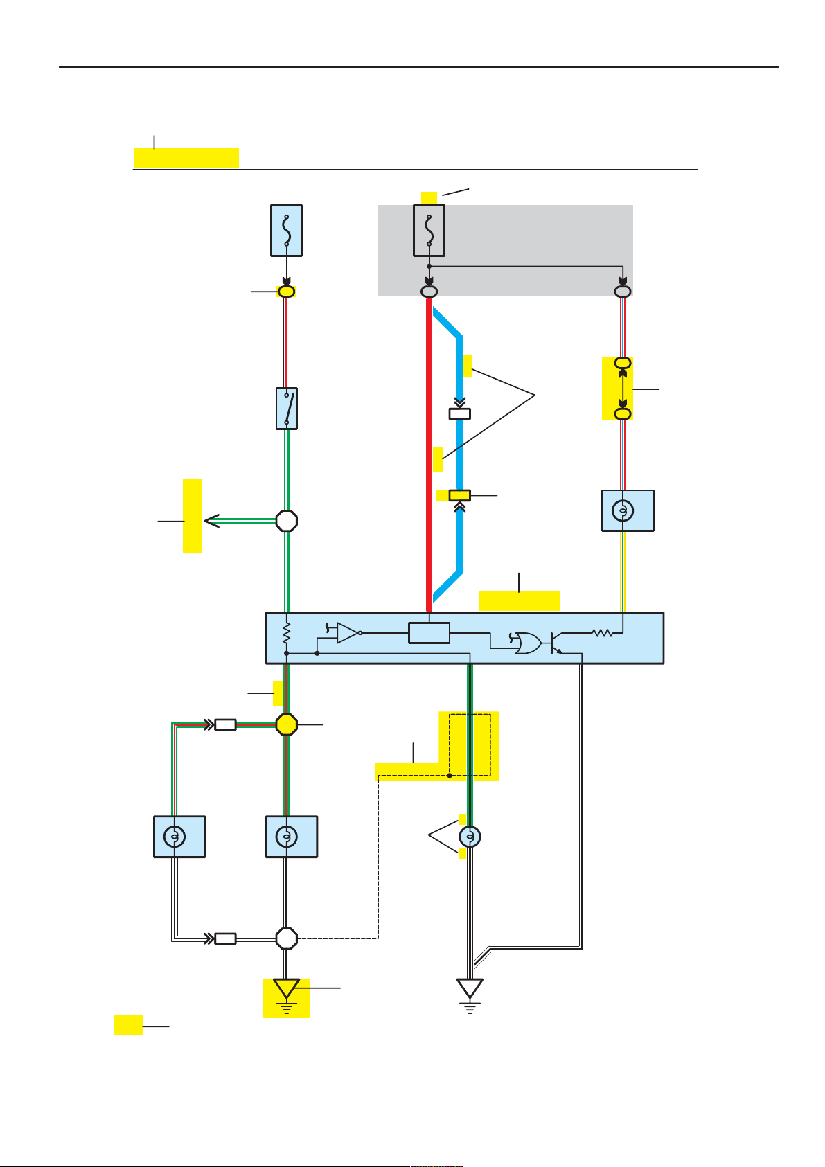
* The system shown here is an EXAMPLE ONLY. It is different to the actual
circuit shown in the SYSTEM CIRCUITS SECTION.
[A]
Stop Light
[D]
Skid Control ECU
with Actuator
[B]
G – W
(BAT)
2
1
W – RG – W
2
1
G – W
15A
STOP
S6
Stop Light SW
(IG)
7.5A
GAUGE
34
IB
R
[N]
(S/D)
[C]
IE114
LL
(W/G)
IE1
15
L
[E]
(S/D) (S/D)
[F]
IB
R – L
3C
7
[G]
3C
15
R – L
4
Rear
Lights
C7
13
Y – G
Combination Meter
L4
7
Light Failure Sensor
12
48
11
[H]
1
G – R
BV1
G – R G – R
4
Stop
Rear Combination
R7
3
W – B G – R
Light RH
1
BV1
3
6
W – BW – B
W – B
BO BL
Stop
[I]
Rear Combination
R6
Light LH
[L]
[J]
(Shielded)
[K]
G – B
2
1
W – B
H17
High Mounted
Stop Light
W – B
4
50
[M]
COROLLA MATRIX (EM0350U)
Page 6
B
[A] :System Title
[B] : Indicates a Relay Block. No shading is used and
only the Relay Block No. is shown to distinguish it
from the J/B
Example: Indicates Relay Block No.1
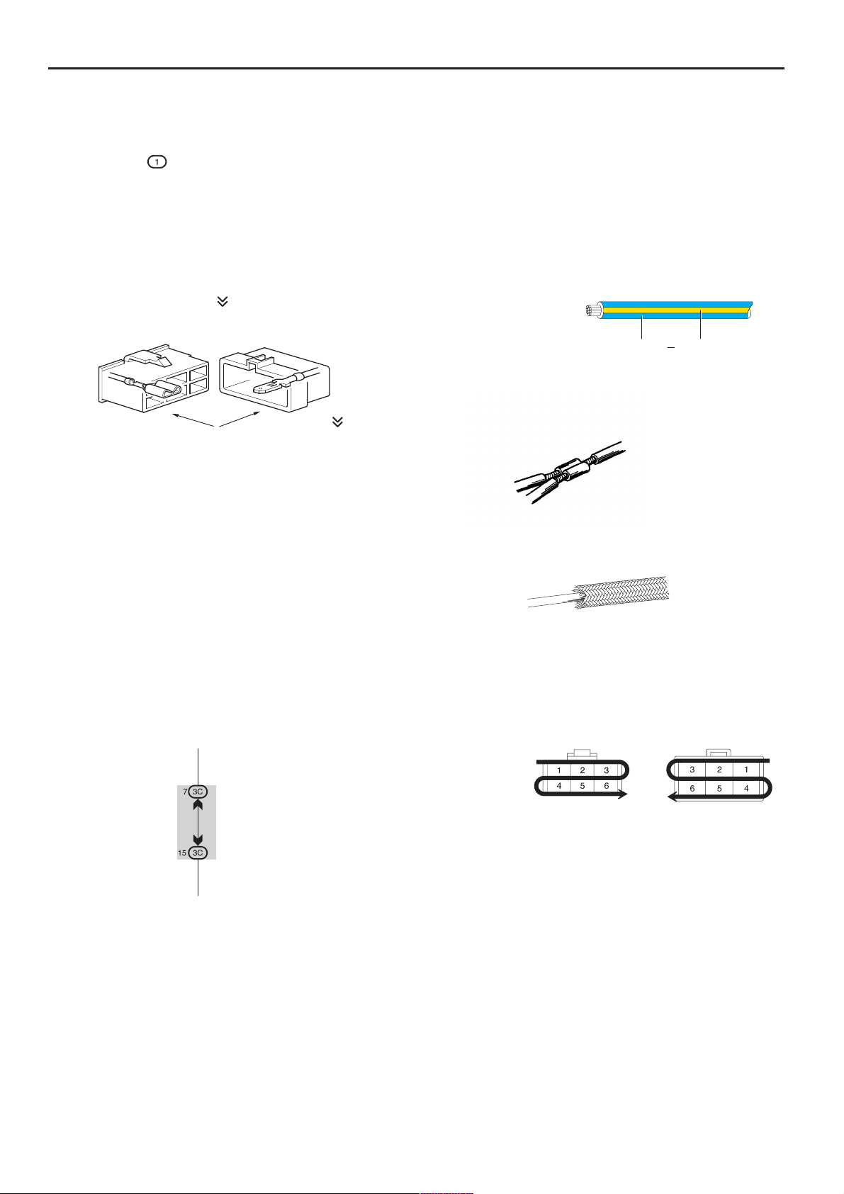
[C] : ( ) is used to indicate diff erent wirin g and
connector, etc. when the vehicle model, engine
type, or specification is different.
[D] : Indicates related system.
[E] : Indicates the wiring harness and wiring harness
connector. The wiring harness with male terminal is
shown with arrows (
).
Outside numerals are pin numbers.
Female Male ( )
The first letter of the code for each wiring harness
and wiring harness connector(s) indicates the
component’s location, e.g, ”E” for the Engine
Compartment, ”I” for the Instrument Panel and
Surroundi ng area, and ”B ” for the Body an d
Surrounding area.
When more than one code has the first and second
letters in common, followed by numbers (e.g, IH1,
IH2), this indicates the same type of wiring harness
and wiring harness connector.
[F] :Represents a part (all parts are shown in sky blue).
The code is the same as the code used in parts
position.
[G] : Junction Block (The number in the circle is the J/B
No. and the connector code is shown beside it).
Junction Blocks are shaded to clearly separate
them from other parts.
[H] :Indicates the wiring color.
Wire colors are indicated by an alphabetical code.
B = Black W = White BR = Brown
L = Blue V = Violet SB = Sky Blue
R=Red G=Green LG=Light Green
P = Pink Y = Yellow GR = Gray
O = Orange
The first letter indicates the basic wire color and the
second letter indicates the color of the stripe.
Example: L – Y
L
(Blue)Y(Yellow)
[I] :Indicates a wiring Splice Point
Example:
[J] : Indicates a shielded cable.
[K] : Indicates the pin number of the connector.
The numbering system is different for female and
male connectors.
Example:
Numbered in order
from upper left to
lower right
Numbered in order
from upper right to
lower left
Example:
3C indicates that
it is inside
Junction Block
No.3
[L] :Indicates a ground point.
The first letter of the code for each ground point(s)
indicates the component’s location, e.g, ”E” for the
Engine Compartment, ”I” for the Instrument Panel
and Surrounding area, and ”B” for the Body and
Surrounding area.
[M] : Page No.
[N] : Indicates the ignition key position(s) when the
power is supplied to the fuse(s).
COROLLA MATRIX (EM0350U)
Female
Male
5
Page 7
B HOW TO USE THIS MANUAL
[O]
[P]
[Q]
[R]
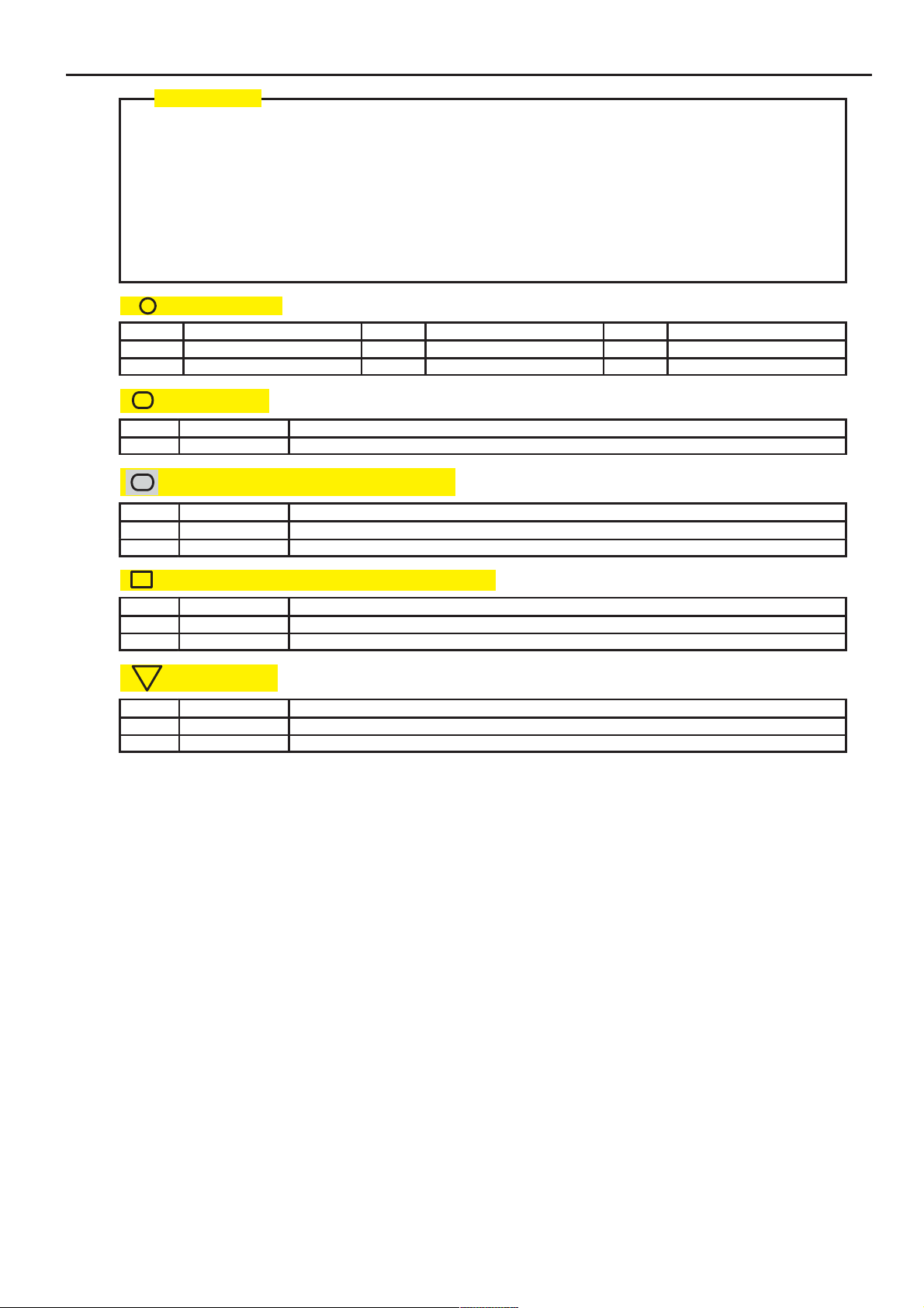
System Outline
Current is applied at all times through the STOP fuse to TERMINAL 2 of the stop light SW.
When the ignition SW is turned on, current flows from the GAUGE fuse to TERMINAL 8 of the light failure sensor, and also flows
through the rear lights warning light to TERMINAL 4 of the light failure sensor.
Stop Light Disconnection Warning
When the ignition SW is turned on and the brake pedal is pressed (Stop light SW on), if the stop light circuit is open, the current
flowing from TERMINAL 7 of the light failure sensor to TERMINALS 1, 2 changes, so the light failure sensor detects the
disconnection and the warning circuit of the light failure sensor is activated.
As a result, the current flows from TERMINAL 4 of the light failure sensor to TERMINAL 11 to GROUND and turns the rear lights
warning light on. By pressing the brake pedal, the current flowing to TERMINAL 8 of the light failure sensor keeps the warning
circuit on and holds the warning light on until the ignition SW is turned off.
: Parts Location
Code See Page Code See Page Code See Page
C7 34 L4 36 R7 37
H17 36 R6 37 S6 35
: Relay Blocks
Code See Page Relay Blocks (Relay Block Location)
1 18 R/B No.1 (Instrument Panel Brace LH)
: Junction Block and Wire Harness Connector
Code See Page Junction Block and Wire Harness (Connector Location)
3C 22 Instrument Panel Wire and J/B No.3 (Instrument Panel Brace LH)
IB 20 Instrument Panel Wire and Instrument Panel J/B (Lower Finish Panel)
[S]
[T]
: Connector Joining Wire Harness and Wire Harness
Code See Page Joining Wire Harness and Wire Harness (Connector Location)
IE1 42 Floor Wire and Instrument Panel Wire (Left Kick Panel)
BV1 50 Luggage Room Wire and Floor Wire (Luggage Room Left)
: Ground Points
Code See Page Ground Points Location
BL 50 Under the Left Center Pillar
BO 50 Back Panel Center
6
COROLLA MATRIX (EM0350U)
Page 8

B
[O] :Explains the system outline.
[P] : Indicates the reference page showing the position on the vehicle of the parts in the system circuit.
Example : Part ”L4” (Light Failure Sensor) is on page 36 of the manual.
∗ The letter in the code is from the first letter of the part, and the number indicates its order in parts
starting with that letter.
Example : L 4
[Q] : Indicates the reference page showing the position on the vehicle of Relay Block Connectors in the system circuit.
Example : Connector ”1” is described on page 18 of this manual and is installed on the left side of the instrument
panel.
[R] : Indicates the reference page showing the position on the vehicle of J/B and Wire Harness in the system circuit.
Example : Connector ”3C” connects the Instrument Panel Wire and J/B No.3. It is described on page 22 of this
manual, and is installed on the instrument panel left side.
Parts is 4th in order
Light Failure Sensor
[S] : Indicates the reference page describing the wiring harness and wiring harness connector (the female wiring
harness is shown first, followed by the male wiring harness).
Example : Connector ”IE1” connects the floor wire (female) and Instrument panel wire (male). It is described on
page 42 of this manual, and is installed on the left side kick panel.
[T] : Indicates the reference page showing the position of the ground points on the vehicle.
Example : Ground point ”BO” is described on page 50 of this manual and is installed on the back panel center.
COROLLA MATRIX (EM0350U)
7
Page 9
B HOW TO USE THIS MANUAL
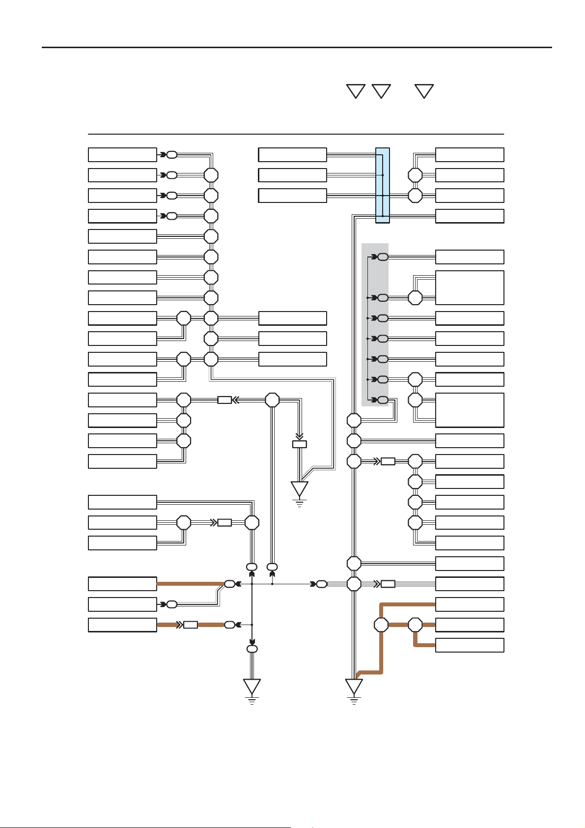
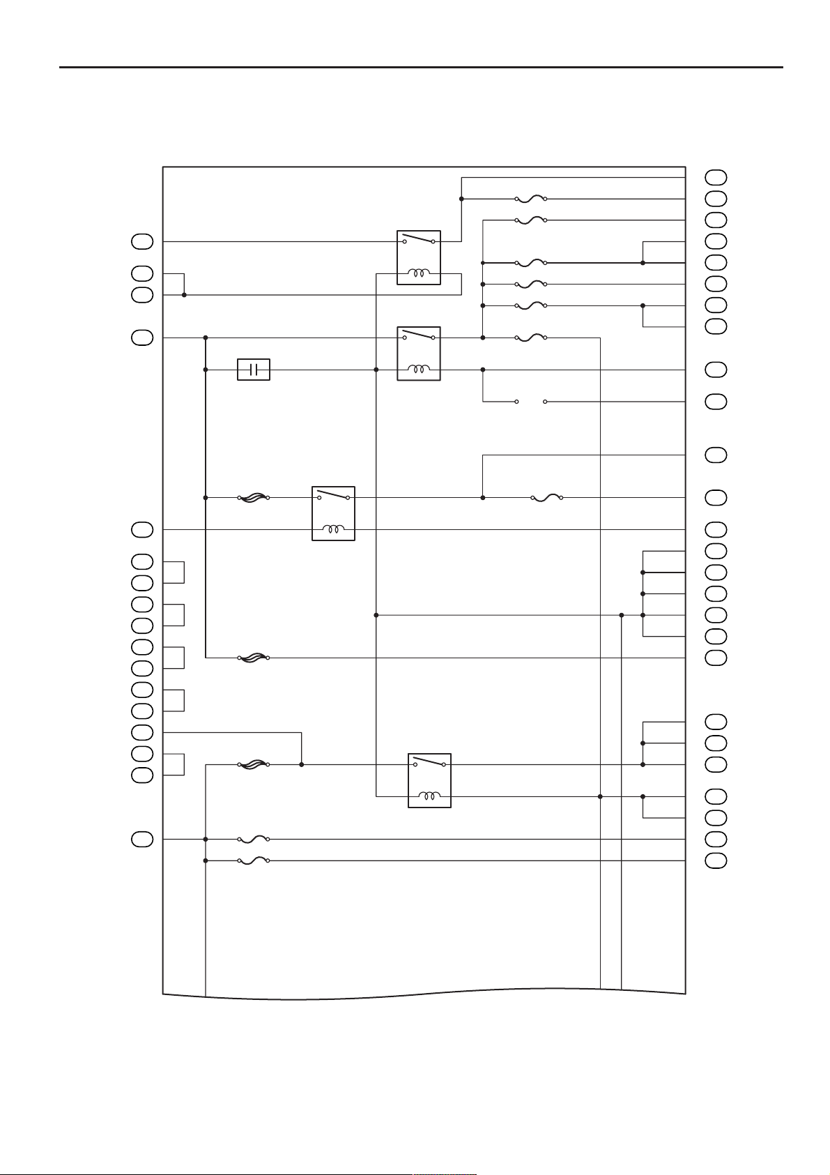
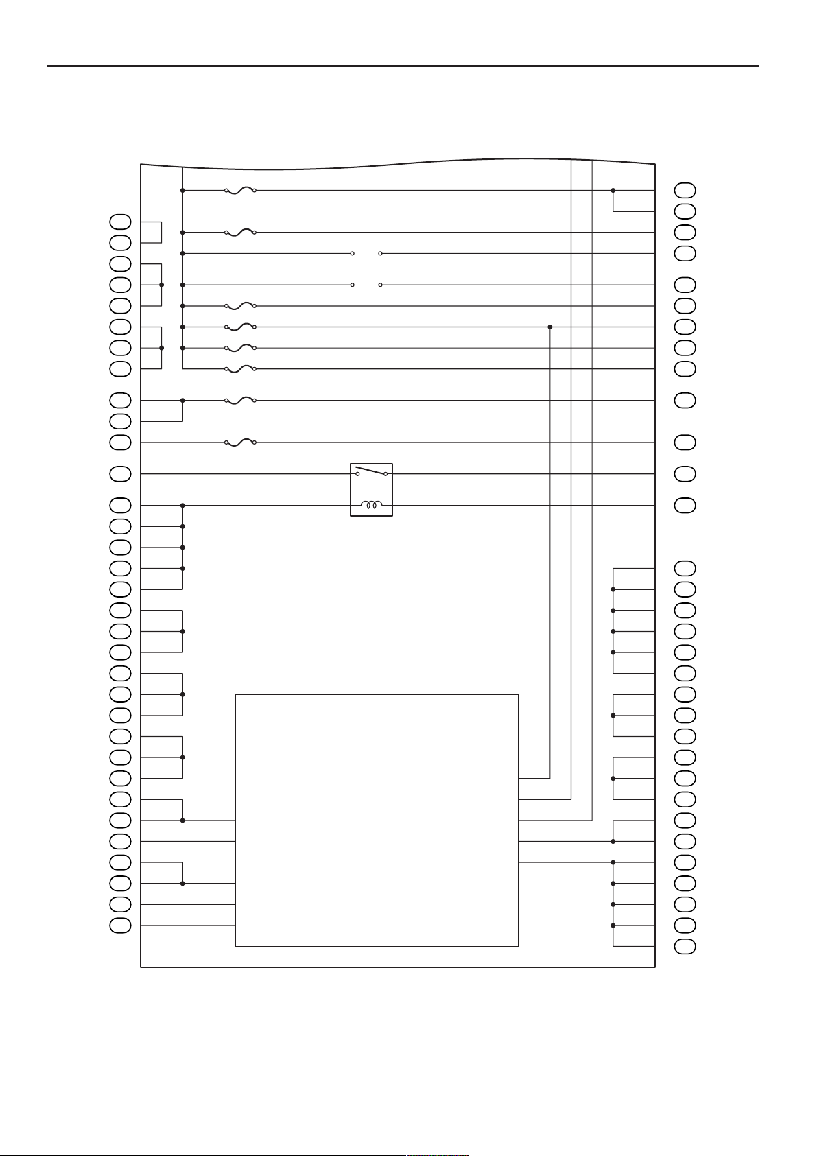
The ground points circuit diagram shows the connections from all major parts to the respective ground points. When
troubleshooting a faulty ground point, checking the system circuits which use a common ground may help you identify
the problem ground quickly. The relationship between ground points (
checked this way.
I GROUND POINT
EA, IB
and
IC
shown below) can also be
FAN MAIN Relay
FAN MAIN Relay
A/C Relay No.2
A/C Relay No.3
Radiator Fan Motor
Headlight Cleaner Relay
Headlight LH
Headlight RH
Front Turn Signal Light RH
Front Clearance Light RH
Front Turn Signal Light LH
Front Clearance Light LH
Door Lock Control SW
Door Courtesy SW RH
Door Lock Motor RH
Door Lock Control Relay
Blower Resistor
Idle–Up SW
A/C Amplifier
Radio and Player
HEATER Relay
Auto Antenna Motor
W–B
5
W–B
5
W–B
5
W–B
5
W–B
W–B
W–B
W–B
W–B W–B
W–B
W–B W–B
W–B
W–B W–B W–B
W–B
W–B
W–B
W–B
W–B W–B W–B
W–B
BR
W–B
4
5
BR BR
W–B
W–B
W–B
W–B
2
IA1
8
IB1
W–B
444
4
4BA1
Cigarette Lighter
O/D Main SW
Clock
Front Fog Light RH
Front Fog Light LH
Brake Fluid Level SW
W–B
W–B
10
EA2
W–B
EA
W–B
W–B
A
W–B
A
W–B
A
A
A
A
J 1
Junction
Connector
7
3B
7
3C
1
3D
3
3F
13
3G
5
3E
6
3E
W–B
W–B
15
ID1
W–B W–B
W–B (4A–GZE)
W–B
4
W–B
3
IC3
BR
W–B
W–B
W–BW–B
W–B
W–B
W–B
W–B
W–B
W–B
W–B
W–B
W–BW–B
W–B
W–B
W–B
W–BW–B W–B
W–B
W–B
W–B
W–B
W–BW–B
A/C Control Assembly
Blower Motor
Blower SW
Parking Brake SW
Combination Meter
Combination SW
Cruise Control ECU
Remote Control Mirror SW
Turn Signal Flasher
Defogger SW
Combination SW
Unlock Warning SW
Power Window Master SW
Power Window Control
Relay
Door Courtesy SW LH
Door Lock Control SW
Door Lock Motor LH
Fuel Control SW
Woofer Speaker Amplifier
BR
Combination Meter
BRBR
Combination Meter
BR
Fuel Sender
W–B
IB
IC
* The system shown here is an EXAMPLE ONLY. It is different to the actual circuit shown in the SYSTEM CIRCUITS SECTION.
8
COROLLA MATRIX (EM0350U)
Page 10
B
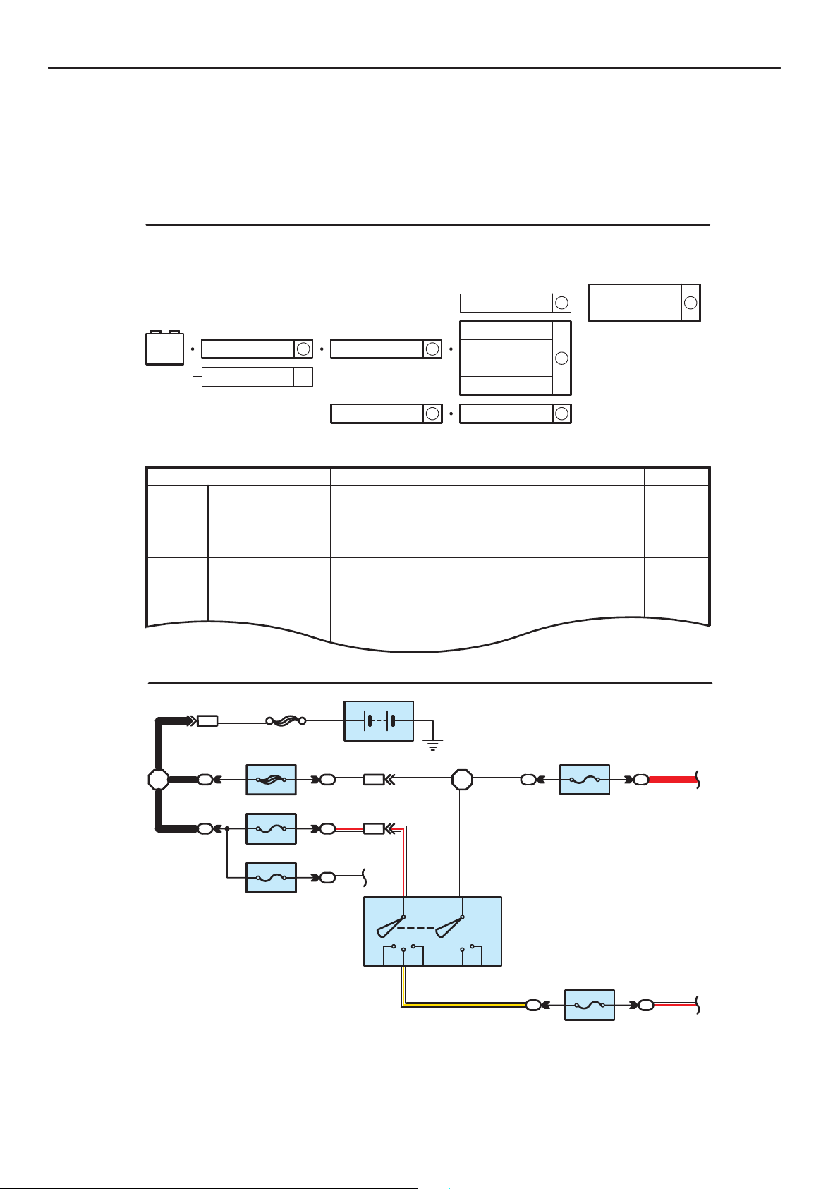
The ”Current Flow Chart” section, describes which parts each power source (fuses, fusible links, and circuit breakers)
transmits current to. In the Power Source circuit diagram, the conditions when battery power is supplied to each system
are explained. Since all System Circuit diagrams start from the power source, the power source system must be fully
understood.
J POWER SOURCE (Current Flow Chart)
The chart below shows the route by which current flows from the battery to each electrical source
(Fusible Link, Circuit Breaker, Fues, etc.) and other parts
Battery
30A AM2
Starter
2
S 2
Fusible Link Block
100A ALT
Engine Room R/B (See Page 20)
System
ABS
ABS and Traction Control
Cruise Control
Electronically Controlled Transmission
Multiplex Communication System
Cigarette Lighter
Combination Meter
Headlight
Interior Light
Key Reminder and Seat Belt Warning
Light Auto Turn Off System
Theft Deterrent and Door Lock Control
20A
10A
Fuse
STOP
DOME
Power Source
6
6
Short Pin
15A EFI
10A HAZARD
20A RADIO NO.1
10A HORN
60A ABS
10A ECU–B
2
7.5A DOME
2
5
2
Page
194
187
180
166
210
214
230
112
122
1
B
BA1
B
2
B
2
1.25B
FL MAIN
W
50A MAIN
7.5A AM1
15A HAZ–RADIO
1
Battery
W – R
W
EB1
EB1
7
6
21
2
21
2
2
2
ACC
WW
W – R
8
AM1
IG1
ST1
2
W
W
4
AM2
I8
Ignition SW
IG2
ST2
B – Y
7.5A DOME
1
1
20A DEFOG
121W – R
1
2
R
1
∗ The system shown here is an EXAMPLE ONLY. It is different to the actual circuit shown in the SYSTEM CIRCUITS SECTION.
9
COROLLA MATRIX (EM0350U)
Page 11
B HOW TO USE THIS MANUAL
K CONNECTOR LIST
I14
Dark Gray
[A]
I15
I16
Gray
[C]
1234
1234
5678
J1 J4 K1 K2 L1
Black
AB
B
AABCCCDDDD
[B]
A
AAA
A
K CONNECTOR LIST
Black
BA1
123 45
678910111213
13 6789101112
12345 76
[D]
Dark Gray
AAA
[E]
12345
1
12 34
567891011
12
BD2
12
Gray
43 21
11
[F]
5678910
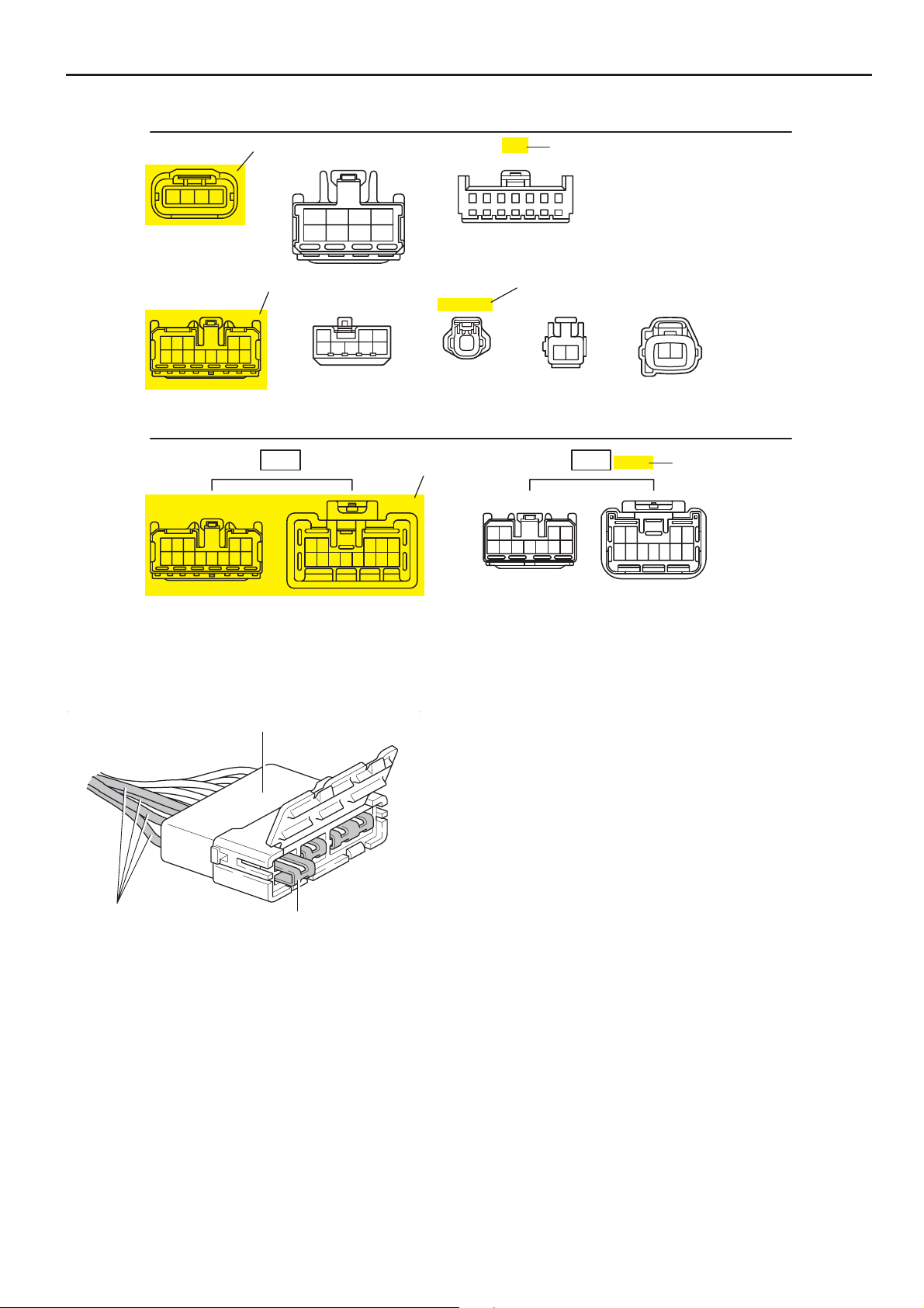
[A] : Indicates connector to be connected to a part. (The numeral indicates the pin No.)
[B] : Junction Connector
Indicates a connector which is connected to a short terminal.
Junction Connector
Junction connector in this manual include a short terminal which is
connected to a number of wire harnesses. Always perform
inspection with the short terminal installed. (When installing the
wire harnesses, the harnesses can be connected to any position
within the short terminal grouping. Accordingly, in other vehicles,
the same position in the short terminal may be connected to a wire
harness from a different part.)
Wire harness sharing the same short terminal grouping have the
same color.
Same Color
Short Terminal
[C] : Parts Code
The first letter of the code is taken from the first letter of part, and the numbers indicates its order in parts which
start with the same letter.
[D] : Connector Color
Connectors not indicated are milky white in color.
[E] : Indicates the connector shapes which are used to join wire harnesses.
On Left : Female connector shapes
On Right : Male connector shapes
Numbers indicate pin numbers.
[F] : Indicates connector colors. (Connectors with not indicated colors are white)
10
COROLLA MATRIX (EM0350U)
Page 12
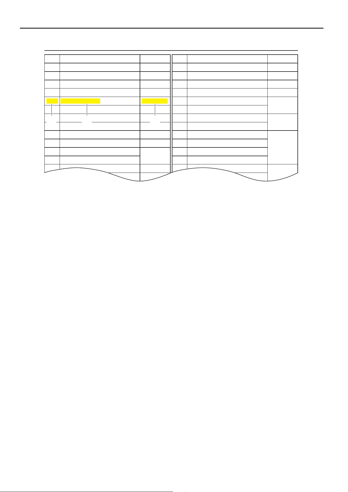
L PART NUMBER OF CONNECTORS
B
Code
A 1
A/C Ambient Temp. Sensor
A 2 A/C Condenser Fan Motor 90980–11237 D 5 Diode (Interior Light) 90980–10962
A 3 A/C Condenser Fan Relay 90980–10940 D 6 Diode (Moon Roof) 90980–11608
A 4 A/C Condenser Fan Resistor 90980–10928
A 5 A/C Magnetic Clutch
A 6 A/T Oil Temp. Sensor
A 7 ABS Actuator
[A]
A 8 ABS Actuator
A 9 ABS Speed Sensor Front LH
ABS Speed Sensor Front RH
A10
A11
Airbag Sensor Front LH Door Courtesy SW Rear LH
A12
Airbag Sensor Front RH Door Courtesy SW Rear RH
A13 Airbag Squib 90980–11194 Door Key Lock and Unlock SW LH
[B] [C]
[A] :Part Code
[B] : Part Name
[C] : Part Number
Toyota Part Number are indicated.
Part Number
90980–11070
90980–11271
90980–11413
90980–11151
90980–11009
90980–10941
90980–11002
90980–11856
90980–11070
Code
D 4 Diode (Courtesy)
D 7 Door Lock Control Relay 90980–10848
D 8 Door Lock Control SW LH
D 9 Door Lock Control SW RH
D10
Door Courtesy SW LH
D11
Door Courtesy SW RH
D12
Door Courtesy SW Front LH
D13
Door Courtesy SW Front RH
D14
D15
D16
D17 Door Key Lock and Unlock SW RH
Part NumberPart NamePart Name
90980–11608
90980–11148
90980–11097
90980–11156
90980–11170
Not all of the above part numbers of the connector are established for the supply.
COROLLA MATRIX (EM0350U)
11
Page 13
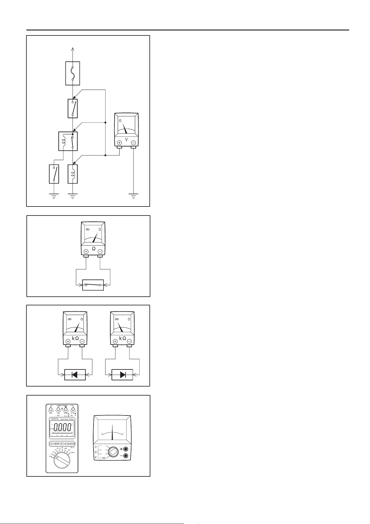
C TROUBLESHOOTING
SW 2
To Ignition SW
IG Terminal
Fuse
[A]
[B]
Relay
[C]
Solenoid
VOLTAGE CHECK
(a) Establish conditions in which voltage is present at the check
point.
Example:
[A] – Ignition SW on
[B] – Ignition SW and SW 1 on
[C] – Ignition SW, SW 1 and Relay on (SW 2 off)
(b) Using a voltmeter, connect the negative lead to a good ground
VoltmeterSW 1
point or negative battery terminal, and the positive lead to the
connector or component terminal.
This check can be done with a test light instead of a voltmeter.
CONTINUITY AND RESISTANCE CHECK
Ohmmeter
SW
Ohmmeter
Diode
Digital Type Analog Type
(a) Disconnect the battery terminal or wire so there is no voltage
between the check points.
(b) Contact the two leads of an ohmmeter to each of the check
points.
If the circuit has diodes, reverse the two leads and check
again.
When contacting the negative lead to the diode positive side
and the positive lead to the negative side, there should be
continuity.
When contacting the two leads in reverse, there should be no
continuity.
(c) U se a volt/ohm meter with high im pedance (10 kΩ/V
minimum) for troubleshooting of the electrical circuit.
12
COROLLA MATRIX (EM0350U)
Page 14
C
Test Light
Disconnect
To Ignition SW
IG Terminal
Fuse Case
Short [A]
SW 1
Short [B]
Disconnect
RelayLight
Short [C]
Disconnect
SW 2 Solenoid
FINDING A SHORT CIRCUIT
(a) Remove the blown fuse and disconnect all loads of the fuse.
(b) Connect a test light in place of the fuse.
(c) Establish conditions in which the test light comes on.
Example:
[A] – Ignition SW on
[B] – Ignition SW and SW 1 on
[C] – Ignition SW, SW 1 and Relay on (Connect the
Relay) and SW 2 off (or Disconnect SW 2)
(d) Disconnect and reconnect the connectors while watching the
test light.
The short lies between the connector where the test light
stays lit and the connector where the light goes out.
(e) Find the exact location of the short by lightly shaking the
problem wire along the body.
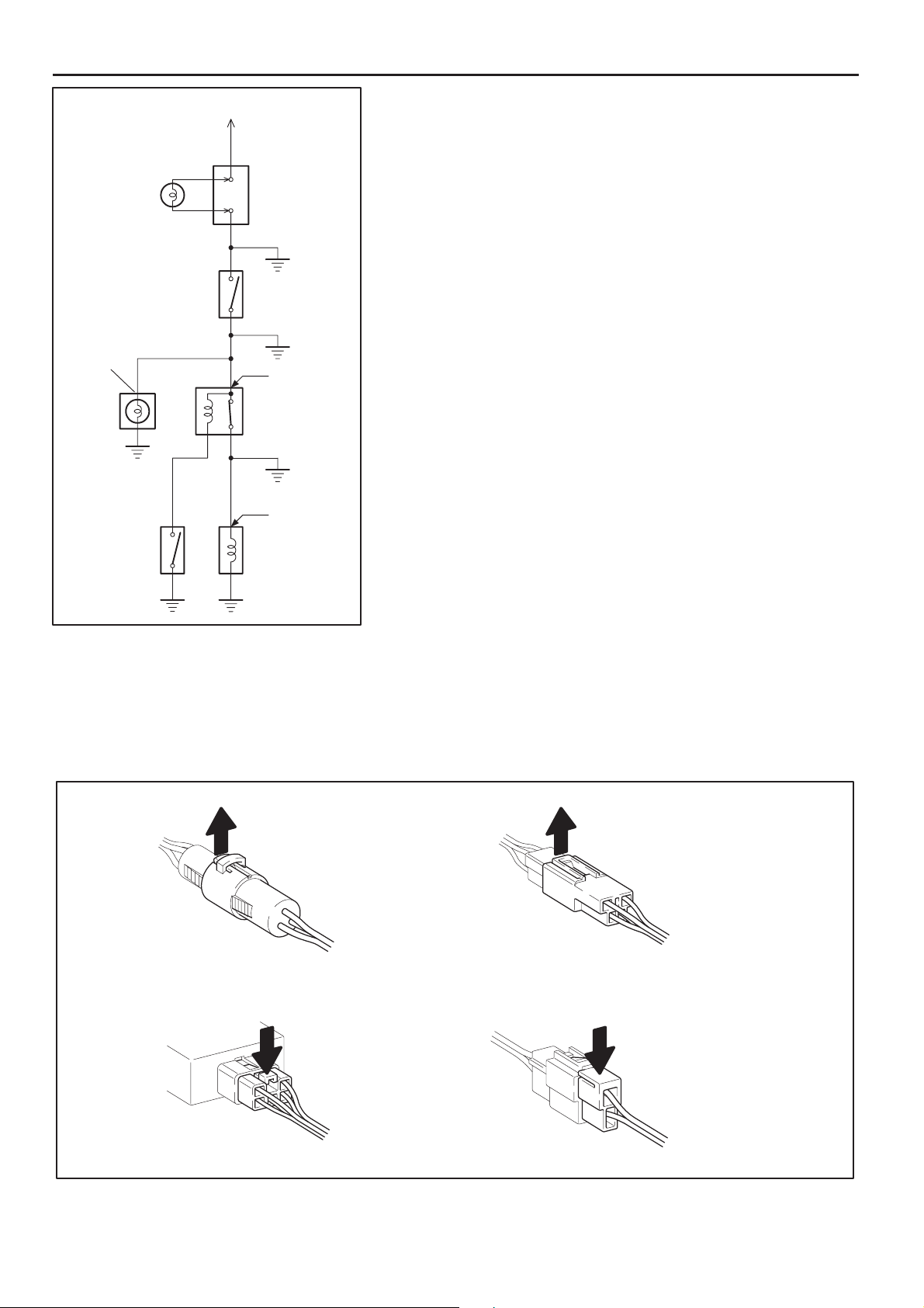
CAUTION:
(a) Do not open the cover or the case of the ECU unless
absolutely necessary. (If the IC terminals are touched,
the IC may be destroyed by static electricity.)
(b) When replacing the internal mechanism (ECU part) of
the digital meter, be careful that no part of your body or
clothing comes in contact with the terminals of leads
from the IC, etc. of the replacement part (spare part).
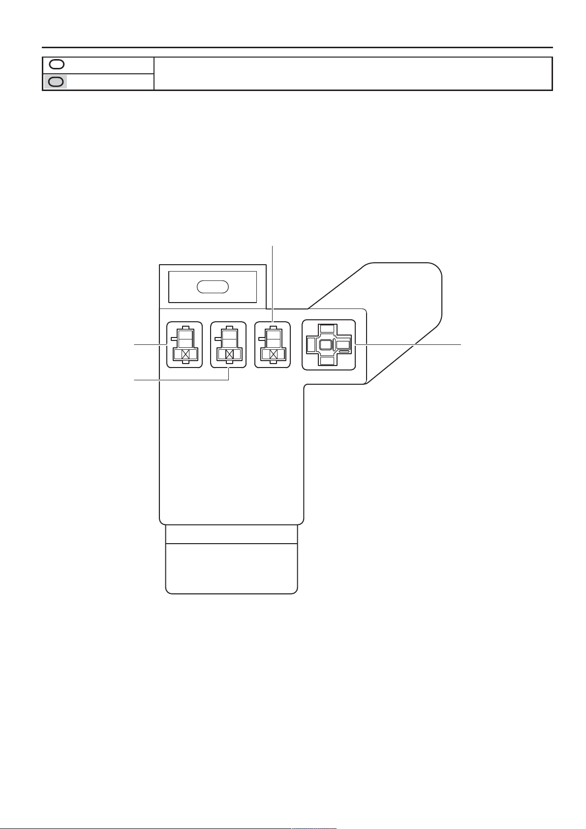
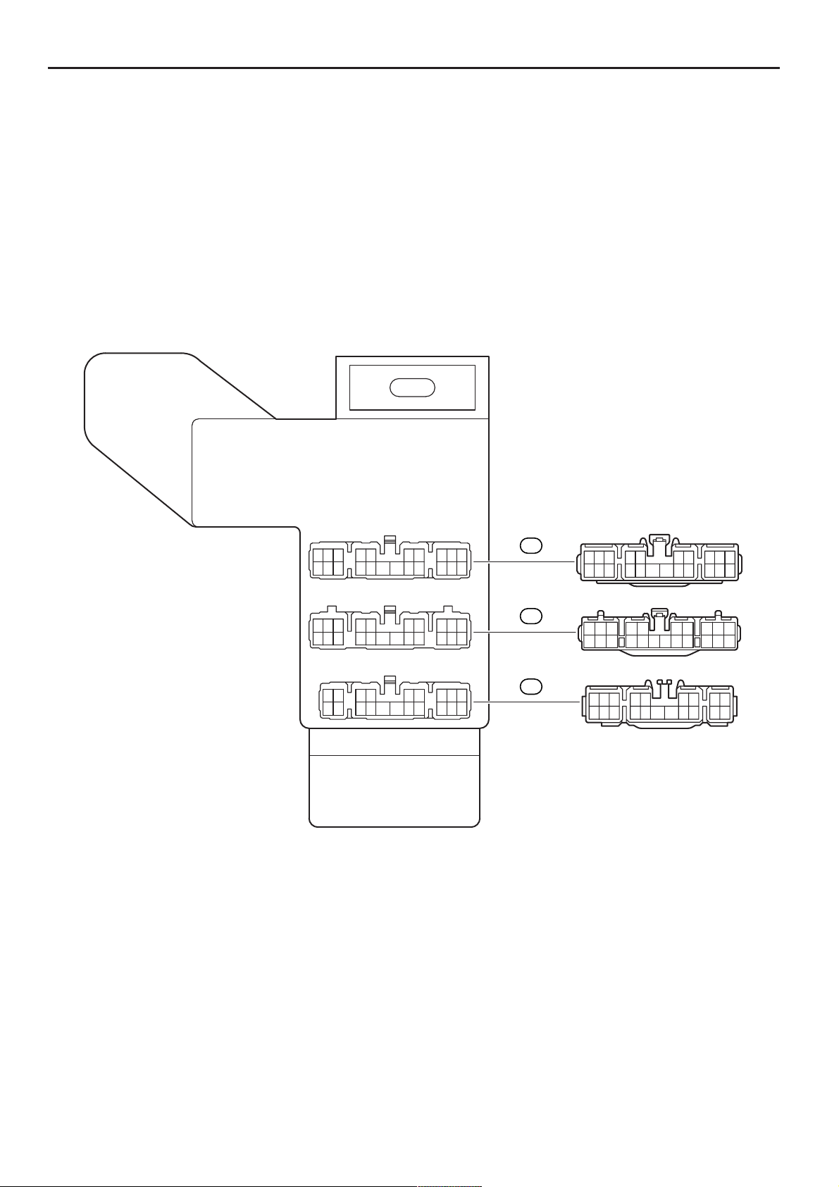
DISCONNECTION OF MALE AND FEMALE
CONNECTORS
To pull apart the connectors, pull on the connector itself, not
the wire harness.
HINT : Check to se e what kind of c onnector you a re
disconnecting before pulling apart.
Pull Up
Press Down Press Down
Pull Up
COROLLA MATRIX (EM0350U)
13
Page 15
C TROUBLESHOOTING
Reference:
!"
!
Example:
(Case 1)
Terminal Retainer
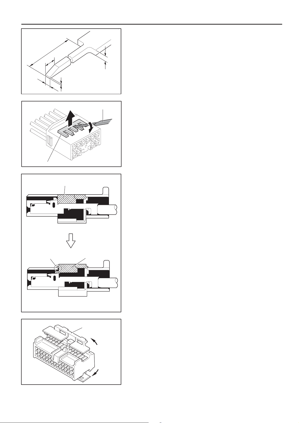
HOW TO REPLACE TERMINAL
(with terminal retainer or secondary locking device)
1. PREPARE THE SPECIAL TOOL
#
"$%
Up
Tool
!
(mm)
HINT : To remove the terminal from the connector, please
construct and use the special tool or like object shown on
the left.
2. DISCONNECT CONNECTOR
3. DIS EN GAGE THE S EC ON DARY LOCKING DEVICE OR
TERMINAL RETAINER.
(a) Locking device must be disengaged before the terminal
locking clip can be released and the terminal removed from
the connector.
(b) Use a special tool or the terminal pick to unlock the secondary
locking device or terminal retainer.
NOTICE:
Do not remove the terminal retainer from connector body.
Terminal Retainer
[Retainer at Full Lock Position]
Stopper
[Retainer at Temporary Lock Position]
Example:
(Case 2)
Terminal
Retainer
Secondary
Locking Device
[A] For Non–Waterproof Type Connector
HINT : The needle insertion position varies according to the
connector’s shape (number of terminals etc.), so
check the position before inserting it.
”Case 1”
Raise the terminal retainer up to the temporary lock
position.
”Case 2”
Open the secondary locking device.
14
COROLLA MATRIX (EM0350U)
Page 16

Tab
Tab
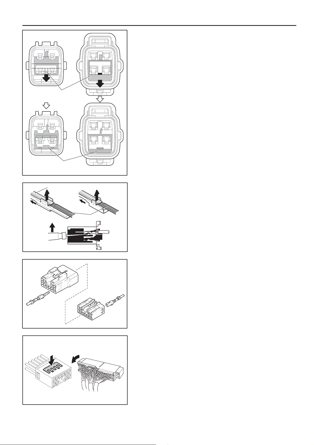
C
Tool
Example:
(Case 1)
Tool
[Male]
Terminal
Retainer
Access Hole
( Mark)
Retainer
at Full Lock Position
[Female]
Tool
[B] For Waterproof Type Connector
HINT : Terminal retainer color i s d ifferent
according to connector body.
Example:
Terminal Retainer
: Connector Body
Black or White : Gray
Black or White : Dark Gray
Gray or White : Black
”Case 1”
Type where terminal retainer is pulled
up to the temporary lock position (Pull
Type).
Insert the special tool into the terminal
retainer access hole (!Mark) and pull
the t erminal retai ner up to the
temporary lock position.
HINT : The needle insertion position varies
according to the connector’s shape
(Number of terminals etc.), so check
the position before inserting it.
Example:
(Case 2)
[Male]
Retainer
at Temporary Lock Position
[Male] [Female]
Terminal Retainer
Tool
Press Down
Press Down
[Female]
COROLLA MATRIX (EM0350U)
”Case 2”
Type whic h cannot be pulled as far as
Power Lock insert the tool straight into
the access hole of terminal retainer as
shown.
Tool
15
Page 17
C TROUBLESHOOTING
Retainer at
Full Lock Position
Retainer at
Temporary Lock Position
[Male] [Female]
Push the terminal retainer down to the temporary lock position.
Locking Lug
(c) Release the locking lug from terminal and pull the terminal out
from rear.
Tool
4. INSTALL TERMINAL TO CONNECTOR
(a) Insert the terminal.
HINT:
1. Make sure the terminal is positioned correctly.
2. Insert the terminal until the locking lug locks firmly.
3. Insert the terminal with terminal retainer in the temporary lock
position.
16
(b) Push the secondary locking device or terminal retainer in to
the full lock position.
5. CONNECT CONNECTOR
COROLLA MATRIX (EM0350U)
Page 18

ABBREVIATIONS
The following abbreviations are used in this manual.
A/C = Air Conditioning
A/T = Automatic Transaxle
ABS = Anti–Lock Brake System
CAN = Controller Area Network
COMB. = Combination
EC = Electrochromic
ECU = Electronic Control Unit
ESA = Electronic Spark Advance
FL = Fusible Link
IC = Integrated Circuit
ABBREVIATIONS D
J/B = Junction Block
LH = Left–Hand
M/T = Manual Transaxle
O/D = Overdrive
R/B = Relay Block
RH = Right–Hand
SFI = Sequential Multiport Fuel Injection
SRS = Supplemental Restraint System
SW = Switch
TEMP. = Temperature
TRAC = Traction Control
TVIP = TOYOTA Vehicle Intrusion Protection
VSC = Vehicle Stability Control
VSV = Vacuum Switching Valve
VVT = Variable Valve Timing
w/ = With
w/o = Without
∗ The titles given inside the components are the names of the terminals (terminal codes) and are not treated as being
abbreviations.
COROLLA MATRIX (EM0350U)
17
Page 19
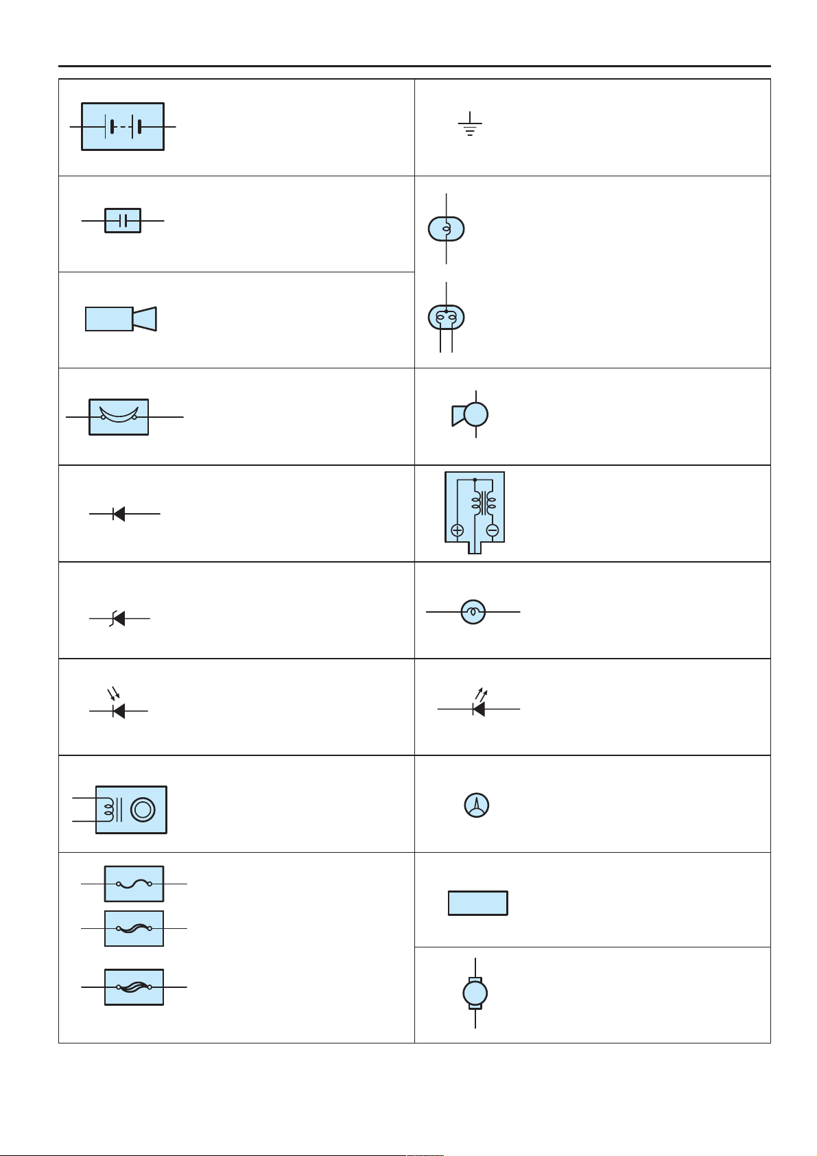
E GLOSSARY OF TERMS AND SYMBOLS
FUSIBLE LINK
FUSIBLE LINK
BATTERY
Stores chemical energy and
converts it into electrical energy.
Provides DC current for the auto’s
various electrical circuits.
CAPACITOR (Condenser)
A small holding unit for temporary
storage of electrical voltage.
CIGARETTE LIGHTER
An electric resistance heating
element.
CIRCUIT BREAKER
Basically a reusable fuse, a circuit
breaker will heat and open if too
much current flows through it.
Some units automatically reset when
cool, others must be manually reset.
DIODE
A semiconductor which allows
current flow in only one direction.
1. SINGLE
FILAMENT
2. DOUBLE
FILAMENT
GROUND
The point at which wiring attaches to
the Body, thereby providing a return
path for an electrical circuit; without a
ground, current cannot flow.
HEADLIGHTS
Current flow causes a headlight
filament to heat up and emit light. A
headlight may have either a single
(1) filament or a double (2) filament
HORN
An electric device which sounds a
loud audible signal.
IGNITION COIL
Converts low–voltage DC current
into high–voltage ignition current for
firing the spark plugs.
(for Medium Current Fuse)
(for High Current Fuse or
Fusible Link)
DIODE, ZENER
A diode which allows current flow in one
direction but blocks reverse flow only up
to a specific voltage. Above that potential,
it passes the excess voltage. This acts as
a simple voltage regulator.
PHOTODIODE
The photodiode is a semiconductor
which controls the current flow
according to the amount of light.
DISTRIBUTOR, IIA
Channels high–voltage current from
the ignition coil to the individual
spark plugs.
FUSE
A thin metal strip which burns through
when too much current flows through it,
thereby stopping current flow and
protecting a circuit from damage.
A heavy–gauge wire placed in high
amperage circuits which burns through on
overloads, thereby protecting the circuit.
The numbers indicate the crosssection
surface area of the wires.
FUEL
M
LIGHT
Current flow through a filament
causes the filament to heat up and
emit light.
LED (LIGHT EMITTING DIODE)
Upon current flow, these diodes emit
light without producing the heat of a
comparable light.
METER, ANALOG
Current flow activates a magnetic
coil which causes a needle to move,
thereby providing a relative display
against a background calibration.
METER, DIGITAL
Current flow activates one or many
LED’s, LCD’s, or fluorescent
displays, which provide a relative or
digital display.
MOTOR
A power unit which converts
electrical energy into mechanical
energy, especially rotary motion.
18
COROLLA MATRIX (EM0350U)
Page 20
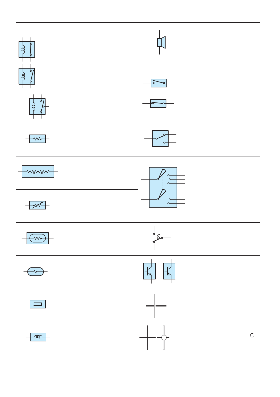
E
Opens and closes
operational.
black dot at the junction are
black dot at the junction are
RELAY
1. NORMALLY
CLOSED
2. NORMALLY
OPEN
RELAY, DOUBLE THROW
RESISTOR
RESISTOR, TAPPED
RESISTOR, VARIABLE or RHEOSTAT
Basically, an electrically operated
switch which may be normally
closed (1) or open (2).
Current flow through a small coil
creates a magnetic field which either
opens or closes an attached switch.
A relay which passes current
through one set of contacts or the
other.
An electrical component with a fixed
resistance, placed in a circuit to
reduce voltage to a specific value.
A resistor which supplies two or
more different non adjustable
resistance values.
A controllable resistor with a variable
rate of resistance.
Also called a potentiometer or
rheostat.
SPEAKER
An electromechanical device which
creates sound waves from current
flow.
SWITCH, MANUAL
Opens and closes
1. NORMALLY
OPEN
2. NORMALLY
CLOSED
SWITCH, DOUBLE THROW
A switch which continuously passes
current through one set of contacts
or the other.
SWITCH, IGNITION
A key operated switch with several
positions which allows various
circuits, particularly the primary
ignition circuit, to become
operational.
circuits, thereby
stopping (1) or
allowing (2) current
flow.
(Reed Switch Type)
SENSOR (Thermistor)
A resistor which varies its resistance
with temperature.
SENSOR, SPEED
Uses magnetic impulses to open
and close a switch to create a signal
for activation of other components.
SHORT PIN
Used to provide an unbroken
connection within a junction block.
SOLENOID
An electromagnetic coil which forms
a magnetic field when current flows,
to move a plunger, etc.
SWITCH, WIPER PARK
Automatically returns wipers to the
stop position when the wiper switch
is turned off.
TRANSISTOR
A solidstate device typically used as
an electronic relay; stops or passes
current depending on the voltage
applied at ”base”.
WIRES
(1) NOT
CONNECTED
(2) SPLICED
Wires are always drawn as
straight lines on wiring
diagrams.
Crossed wires (1) without a
not joined;
crossed wires (2) with a
black dot or octagonal ( )
mark at the junction are
spliced (joined)
connections.
19
COROLLA MATRIX (EM0350U)
Page 21
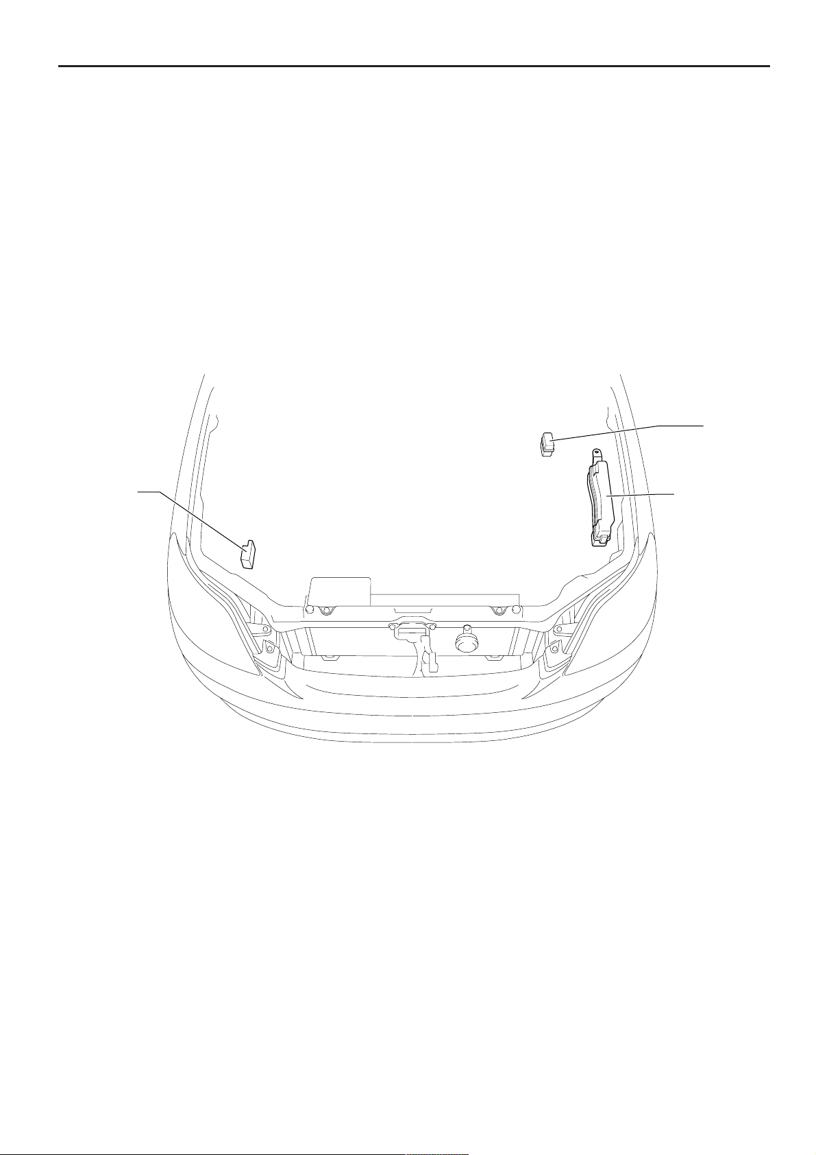
F RELAY LOCATIONS
[Engine Compartment]
ABS R/B
Skid Control
ECU with
Actuator
Engine Room
R/B
Engine Room
J/B
20
COROLLA MATRIX (EM0350U)
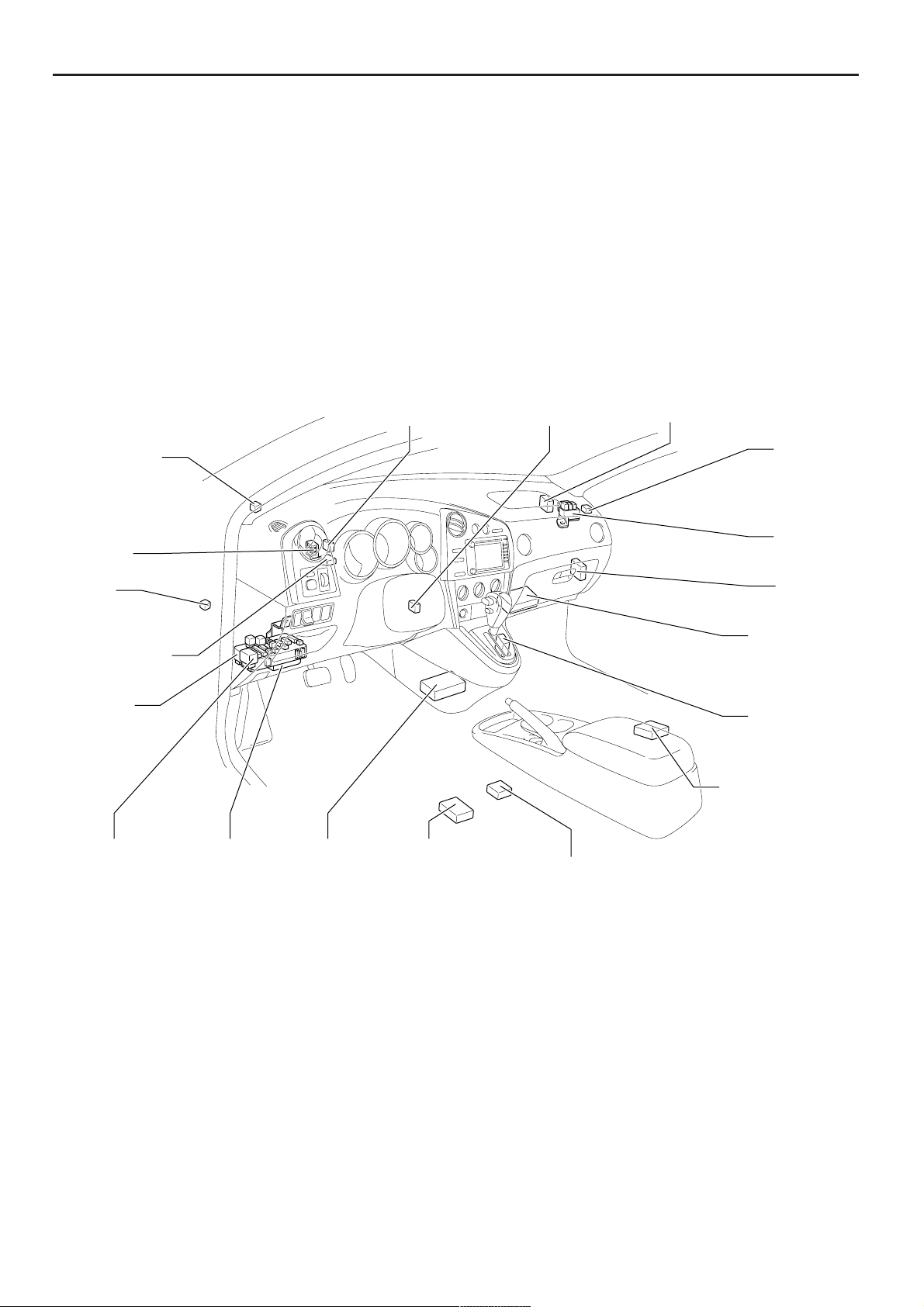
Page 22
l
t
C
I
T
C
A
C
I
P
t
[Instrument Panel]
F
utomatic Light
ontrol Sensor
enter J/B
G Relay
ransponder Key
omputer
nstrument
anel J/B
Daytime Running
Light Relay
Transponder Key
Amplifier
Glass Breakage
Sensor ECU
Starter Cu
Relay
RH R/B
RH J/B
TVIP ECU
Engine Contro
Module
Shift Lock
Control ECU
Stereo Componen
Amplifier
Turn Signal
Flasher Relay
Integration
Relay
Airbag Sensor
Assembly
Voltage
Inverter
Yaw Rate Sensor
21
COROLLA MATRIX (EM0350U)
Page 23
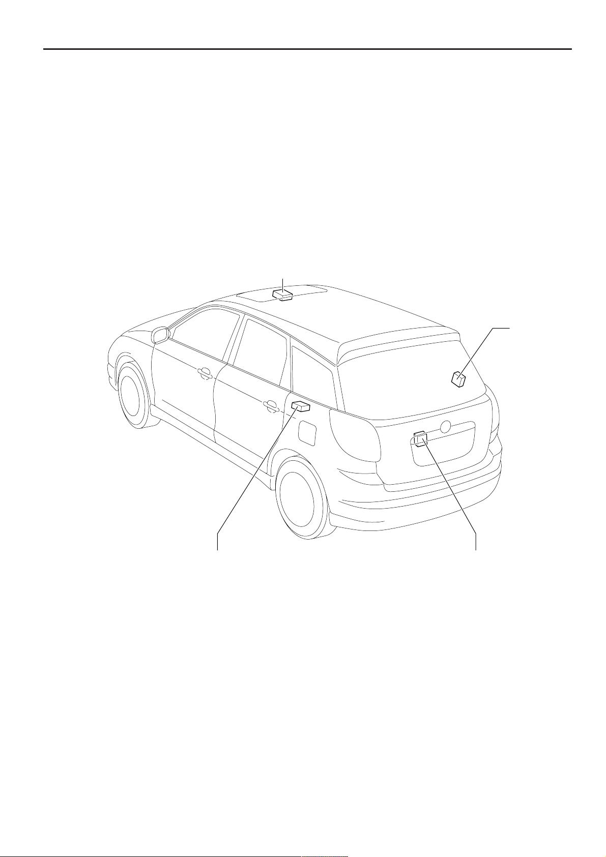
l
F RELAY LOCATIONS
[Body]
Moon Roof Control
Relay and SW
Door Contro
Receiver
22
Occupant Classification ECU
COROLLA MATRIX (EM0350U)
Rear Wiper Relay
Page 24
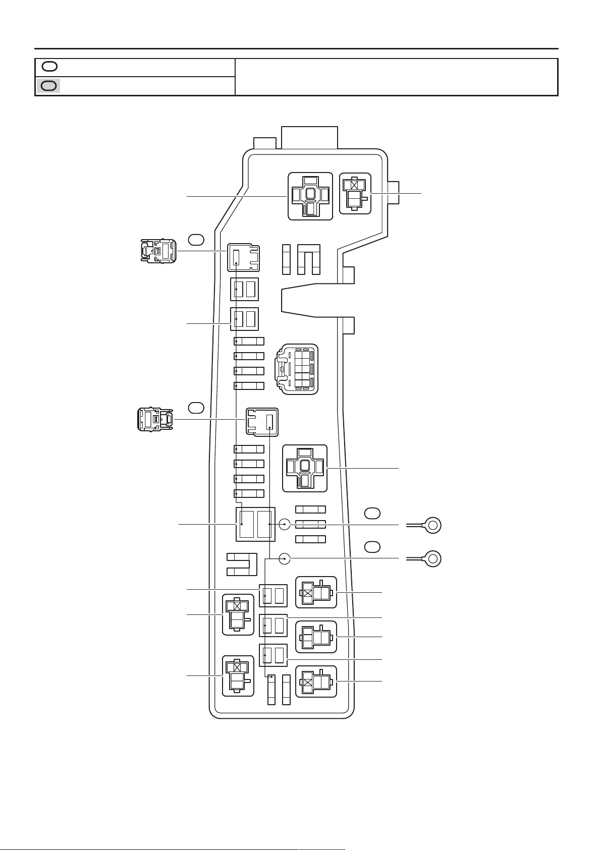
1
Engine Compartment Left (See Page 20)
: Engine Room R/B
: Engine Room J/B
* 1:w/ VSC
* 2:w/o VSC
F
HEAD Relay
1
(from Engine Wire)
40A HEAD MAIN
(for High Current)
Gray
1
(from Engine Wire)
1A
1B
1
12
5A
1
ALT-S
20A
1
EFI
10A
1
HAZARD
10A
HORN
DOME
15A
MAIN
30A
1
AMP
30A
1
ETCS
10A
1
5
12
3
11
10A
15A
EFI2
2
2
2
21
1
21
2
2
2
10A
222
HEAD LH LWR
HEAD RH LWR
5
12
3
1
2
5
3
M/G CLT Relay
DIMMER Relay
100A ALT
(for High Current)
50A ABS NO.2
(for High Current) (*1)
40A ABS NO.2
(for High Current) (*2)
EFI Relay
FOG Relay
12
HAED RH UPR
2210A
1
10A
HAED LH UPR
12
5
3
12
5
3
21
12
21
1
15A
2
FOG
1C
1
(from Engine Room Main Wire)
1D
1
(from Engine Room Main Wire)
1
35
2
1
4
35
2
1
35
2
HORN Relay
40A RDI FAN
(for High Current)
FAN NO.2 Relay
30A ABS NO.1
(for High Current)
FAN NO.1 Relay
23
COROLLA MATRIX (EM0350U)
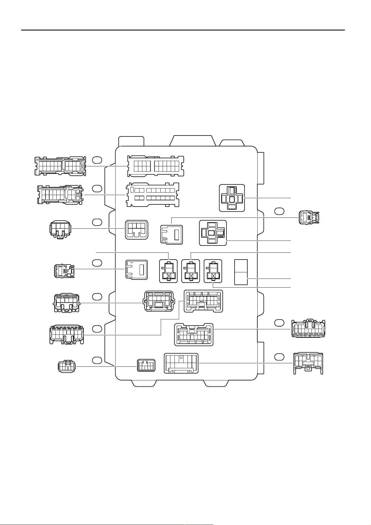
Page 25
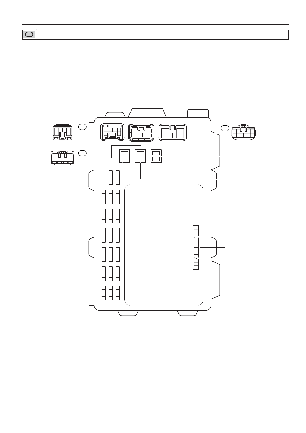
F RELAY LOCATIONS
: Instrument Panel J/B Lower Finish Panel (See Page 21)
IM
3456
12
(from Instrument Panel Wire)
12 34
5 6 7 8 9 1011
IL
(from Instrument Panel Wire)
40A HEATER
(for High Current)
34 56
1
A/C
10A
15A
15A
AM2
RR WIPER
10A
25A
WIPER
ECU-IG
25A
AM1
25A
7.5A
OBD
DOOR
43
2
1110
2
1
10A
M-HTR/DEF I-UP
15A
WASHER
10A
GAUGE
CIG
15A
10A
ECU-B
15A
P/POINT
21
56789
10
124
567839
IK
12
6 7 8 9 10
5
34
(from Instrument Panel Wire)
1
2
2
1
12
11
10
9
8
7
6
5
4
3
2
1
30A POWER
(for High Current)
30A DEFOG
(for High Current)
Integration Relay
24
INV
15A
15A
15A
TAIL
STOP
COROLLA MATRIX (EM0350U)
Page 26
F
3
9 108762541
192018171612 151411 13
(from Floor Wire)
87625413
16151410 13129 11
(from Engine Room Main Wire)
Gray
3456
2
1
(from Roof Wire)
C/OPN Relay
Gray
1
(from Engine Room Main Wire)
34567
21
(from Instrument Panel Wire)
678910111213
12345
(from Instrument Panel Wire)
12 3
45678
(from Instrument Panel Wire)
ID
IC
IE
IB
IG
IF
910 8 7 6 254 13
1920 18 17 16 1215 14 1113
3456
12
12345678
910111213141516
1
1
2
3
12
5
35
ST Relay
IA
1
(from Engine Room Main Wire)
DEF Relay
P/W Relay
1
3
5
12
3
5
12
3
5
12
2
1
Noise Filter
IG1 Relay
76543
2
1
6 7 8 9 10111213
12 3 5
4
12345
678910111213
IH
123 45
6 7 8 9 10111213
(from Instrument Panel Wire)
Yellow
II
IJ
87654
123
5 6 7 8 9 10
12 34
10
56789
1234
(from Instrument Panel Wire)
COROLLA MATRIX (EM0350U)
25
Page 27
F RELAY LOCATIONS
[Instrument Panel J/B Inner Circuit]
ST Relay
3
2
IG1 Relay
5
2
3
1
5
2
11
1
IM
IL
4
IC
1
IA
5
IF
6
II
2
IJ
1
II
4
IJ
2
II
5
IJ
7
II
6
IJ
1
IF
5
II
1
IJ
1
IB
Noise Filter
21
21
30A DEFOG
21
40A HEATER
21
30A POWER
10A ECU-B
25A AM1
DEF Relay
5
2
5
1
3
1
P/W Relay
15A AM2
15A RR WIPER
25A WIPER
15A WASHER
10A ECU-IG
10A GAUGE
10A M-HTR/DEF I-UP
3
1
11
11
13
10
10
10
18
12
3
IM
6
IM
ID
7
IL
IC
9
IC
9
IF
IC
2
IF
3
IH
4
IM
8
IL
IL
4
IF
IH
1
IE
3
II
II
2
IM
7
IG
ID
2
IE
2
IG
5
IE
1
IH
IF
26
(Cont. Next Page)
COROLLA MATRIX (EM0350U)
Page 28
(Cont'd)
F
11
12
13
12
10
20
10
15A STOP
6
IE
3
IG
5
IH
5
IG
6
IG
IH
IH
IH
3
IC
7
IF
6
IF
4
IG
5
IL
6
IL
8
IK
8
II
IC
5
IC
7
ID
1
IL
2
IC
2
ID
2
IL
6
ID
9
IK
IK
5
IK
ID
8
IJ
3
IL
1
ID
ID
8
ID
15A TAIL
15A INV
25A DOOR
15A P/POINT
7.5A OBD
10A A/C
15A CIG
3
ACT-
4
KSW
5
DCTY
8
PRG
7
RDA
C/OPN Relay
5
1
Integration Relay
3
2
IG
GND
ACT+
P-DR
1
B
10
9
2
6
14
13
19
13
17
12
14
15
16
2
IH
IC
7
IH
IF
8
IH
9
IH
4
IH
6
IH
7
IJ
5
IM
8
IF
ID
1
IG
7
IC
4
IL
4
ID
ID
3
IE
4
IE
8
IC
ID
1
IK
1
IC
ID
9
IL
2
IK
9
ID
ID
ID
ID
4
IK
3
IK
COROLLA MATRIX (EM0350U)
27
Page 29
F RELAY LOCATIONS
Right Side of the Instrument Panel Reinforcement (See Page 21)
3
: RH R/B
: RH J/B
P-POINT Relay
INV Relay
TAIL Relay
3
5
12
3
5
12
3
5
12
1
35
4
2
HTR Relay
28
COROLLA MATRIX (EM0350U)
Page 30
F
13245678910
111312141516171819202122
3A
132 4 5 6 7 8 9 10
11 1312 1415 16 17 18 19 20 2122
(from Instrument Panel Wire)
13245678910
111312141516171819202122
3B
132 4 5 6 7 8 9 10
11 1312 14 15 16 17 18 19 20 21 22
(from Instrument Panel Wire)
423156789
13 1112 1014151617181920
3C
13245 6789
10 1211 1314 15 16 17 18 19 20
(from Instrument Panel Wire)
COROLLA MATRIX (EM0350U)
29
Page 31

F RELAY LOCATIONS
[RH J/B Inner Circuit]
10
10
10
11
12
1
3A
2
3A
3
3A
4
3A
5
3A
6
3A
7
3A
8
3A
9
3A
3A
1
3B
2
3B
3
3B
4
3B
5
3B
6
3B
7
3B
8
3B
9
3B
3B
1
3C
2
3C
3
3C
4
3C
5
3C
6
3C
7
3C
8
3C
9
3C
3C
3C
3C
11
12
13
14
15
16
17
18
19
20
21
22
11
12
13
14
15
16
17
18
19
20
21
22
14
15
16
17
18
19
20
13
3A
3A
3A
3A
3A
3A
3A
3A
3A
3A
3A
3A
3B
3B
3B
3B
3B
3B
3B
3B
3B
3B
3B
3B
3C
3C
3C
3C
3C
3C
3C
3C
30
COROLLA MATRIX (EM0350U)
Page 32

2
: ABS R/B Near the Front Left Suspension Tower (See Page 20)
F
12
5
3
5
12
3
ABS MTR RelayABS MTR CUT Relay
COROLLA MATRIX (EM0350U)
31
Page 33

F RELAY LOCATIONS
: Center J/B Behind the Combination Meter (See Page 21)
13245678910
111312141516171819202122
4A
132 4 5 6 7 8 9 10
11 1312 1415 16 17
18 19 20 2122
(from Instrument Panel Wire)
13245678910
111312141516171819202122
4B
1 2 3 4 5 6 7 8 9 10
11 12 13 14 15 16 17 18 19 20 21 22
(from Instrument Panel Wire)
423156789
13 1112 101417 1518 161920
4C
13245 6789
10 1211 1314 15 16 17 18 19 20
(from Instrument Panel Wire)
32
COROLLA MATRIX (EM0350U)
Page 34

[Center J/B Inner Circuit]
F
10
10
10
11
12
1
4A
2
4A
3
4A
4
4A
5
4A
6
4A
7
4A
8
4A
9
4A
4A
1
4B
2
4B
3
4B
4
4B
5
4B
6
4B
7
4B
8
4B
9
4B
4B
1
4C
2
4C
3
4C
4
4C
5
4C
6
4C
7
4C
8
4C
9
4C
4C
4C
4C
11
12
13
14
15
16
17
18
19
20
21
22
11
12
13
14
15
16
17
18
19
20
21
22
13
14
15
16
17
18
19
20
4A
4A
4A
4A
4A
4A
4A
4A
4A
4A
4A
4A
4B
4B
4B
4B
4B
4B
4B
4B
4B
4B
4B
4B
4C
4C
4C
4C
4C
4C
4C
4C
COROLLA MATRIX (EM0350U)
33
Page 35

G ELECTRICAL WIRING ROUTING
Position of Parts in Engine Compartment
C1 A24 E2 B2 F6
C2
C4
G2
A3
G1
F4
H4
H3
F5
A 1 A/C Magnetic Clutch
A 2 ABS Speed Sensor Front LH
A 3 ABS Speed Sensor Front RH
A 4 Airbag Sensor Front LH
A 5 Airbag Sensor Front RH
A 6 Ambient Temp. Sensor
A24 Air Fuel Ratio Sensor (Bank 1 Sensor 1)
B 1 Back–Up Light SW
B 2 Brake Fluid Level Warning SW
C 1 Camshaft Position Sensor
C 2 Camshaft Timing Oil Control Valve (VVT)
C 4 Crankshaft Position Sensor
E 1 Electronically Controlled Transmission Solenoid
E 2 Engine Coolant Temp. Sensor
A2
B1
F3
H2
H1
E1A1A5F2 H6A6 A4 F1
F 1 Front Fog Light LH
F 2 Front Fog Light RH
F 3 Front Parking Light LH
Front Turn Signal Light LH
F 4 Front Parking Light RH
Front Turn Signal Light RH
F 5 Front Washer Motor
F 6 Front Wiper Motor
G 1 Generator
G 2 Generator
H 1 Headlight LH (High)
H 2 Headlight LH (Low)
H 3 Headlight RH (High)
H 4 Headlight RH (Low)
H 6 Horn
34
COROLLA MATRIX (EM0350U)
Page 36

Position of Parts in Engine Compartment
I6 I2 I3I7 I4 I8 I5 I9 V1N1 V5
G
M1
J1
P2
S1
P3
W2
R3
I 2 Ignition Coil and Igniter No.1
I 3 Ignition Coil and Igniter No.2
I 4 Ignition Coil and Igniter No.3
I 5 Ignition Coil and Igniter No.4
I 6 Injector No.1
I 7 Injector No.2
I 8 Injector No.3
I 9 Injector No.4
J 1 Junction Connector
K 1 Knock Sensor (Bank 1)
M 1 Mass Air Flow Meter
T6
S3S2O2K1 P1 R1 R2
P 1 Park/Neutral Position SW
P 2 Power Steering Oil Pressure SW
P 3 Pressure SW
R 1 Radiator Fan Motor
R 2 Radiator Fan Resistor
R 3 Rear Washer Motor
S 1 Skid Control ECU with Actuator
S 2 Starter
S 3 Starter
T 6 Throttle Control Motor
Throttle Position Sensor
N 1 Noise Filter (Ignition)
O 2 Oil Pressure SW
V 1 Vehicle Speed Sensor (Combination Meter)
V 5 VSV (Purge)
W 2 Washer Level Sensor
35
COROLLA MATRIX (EM0350U)
Page 37

G ELECTRICAL WIRING ROUTING
5
(*1)
(*2)
(*1)
(*2)
Position of Parts in Instrument Panel
A25
C10
D4
C15
D1
C18A18 D2 C12C11 C14 A7 C17
A17 B5 A11
* 1:w/ Side Airbag and / or
Separate Type Amplifier
* 2:w/o Side Airbag and
Built-In Type Amplifier
A1
B4
D3
B3
E3
E4
E5
E6
A13A16C13D18 A14
C8 A9 C9
A 7 A/C SW
Air Inlet Control SW
A 9 A/T Shift Lever Illumination
O/D Main SW
A 11 Air Inlet Control Servo Motor
A12 Airbag Sensor Assembly
A13 Airbag Sensor Assembly
A14 Airbag Sensor Assembly
A15 Airbag Squib (Front Passenger Airbag Assembly)
A16 Airbag Squib (Steering Wheel Pad)
A17 Antenna Amplifier
A18 Automatic Light Control Sensor
A25 Accel Position Sensor
B 3 Blower Motor
B 4 Blower Resistor
B 5 Blower SW
A12
A12
A14
C 8 Cigarette Lighter
Power Outlet (Front)
C 9 Cigarette Lighter Illumination
C10 Clutch Start SW
C 11 Combination Meter
C12 Combination SW
C13 Combination SW
C14 Combination SW
C15 Cruise Control Clutch SW
C17 Clock
Front Passenger Seat Belt Warning Light
Option Connector
(Passenger Airbag ON–OFF Indicator Light)
C18 Combination Meter
D 1 Data Link Connector 3
D 2 Daytime Running Light Relay
D 3 Defroster Mode SW
D 4 Diode (IG Relay)
D18 Diode (Rear Wiper)
36
E 3 Engine Control Module
E 4 Engine Control Module
E 5 Engine Control Module
E 6 Engine Control Module
COROLLA MATRIX (EM0350U)
Page 38

Position of Parts in Instrument Panel
4
3
(*4)
(*3)
G
* 3:Separate Type Amplifier
* 4:Built-In Type Amplifier
J13
V10
J2
I10
R7
R8
G4
T2
M2T10 H7R16
R6 R16
R17P5 J3 S6G3
J4
J5
T3
J6
J7
S1
S1
G 3 Glass Breakage Sensor ECU
G 4 Glass Hatch Opener SW
H 7 Hazard SW
H 8 Heated Oxygen Sensor (Bank 1 Sensor 2)
I 10 IG Relay
I 11 Ignition SW
I 12 Integration Relay
J 2 Junction Connector
J 3 Junction Connector
J 4 Junction Connector
J 5 Junction Connector
J 6 Junction Connector
J 7 Junction Connector
J 13 Junction Connector
M 2 Main SW
P 4 Parking Brake SW
P 5 Power Outlet (115V)
P 6 Power Outlet (Rear)
H8I11U1 T9S12S7T7 T8S4I12 S5Y1V6
P4 P6
R 6 Rear Window Defogger SW
R 7 Remote Control Mirror SW
R 8 Rheostat
R16 Radio and Player
R17 Radio and Player
S 4 Security Indicator
S 5 Shift Lock Control ECU
S 6 Starter Cut Relay
S 7 Stop Light SW
S12 Steering Sensor
S13 Stereo Component Amplifier
S14 Stereo Component Amplifier
T 2 Turn Signal Flasher Relay
T 3 TVIP ECU
T 7 Tire Pressure Warning Reset SW
T 8 TRAC OFF SW
T 9 Transponder Key Amplifier
T 10 Transponder Key Computer
U 1 Unlock Warning SW
V 6 Voltage Inverter
V10 VSC Warning Buzzer
Y 1 Yaw Rate Sensor
COROLLA MATRIX (EM0350U)
37
Page 39

G ELECTRICAL WIRING ROUTING
0
2
(*1)
(*2)
(*3)
(*4)
(*3)B7(*4)
Position of Parts in Body
D11
D13
D14
F8
D7
F9 I13 I14C19 D15 D12D8
D8
D17C20 H9
* 1:Built-In Type Amplifier
* 2:Separate Type Amplifier
* 3:w/ Side Airbag and / or
Separate Type Amplifier
* 4:w/o Side Airbag and
Built-In Type Amplifier
D6
D1
G5
J1
D5
B6
D16 B7
A19 ABS Speed Sensor Rear LH
A20 ABS Speed Sensor Rear RH
B 6 Back Door Courtesy SW
Back Door Lock Motor
B 7 Buckle SW LH
Seat Position Sensor
B 8 Buckle SW RH
Occupant Detection Sensor
C19 Curtain Shield Airbag Squib LH
C20 Curtain Shield Airbag Squib RH
D 5 Diode (Door Courtesy)
D 6 Door Control Receiver
D 7 Door Courtesy SW Front LH
D 8 Door Courtesy SW Front RH
D 9 Door Courtesy SW Rear LH
D10 Door Courtesy SW Rear RH
D 11 Door Key Lock and Unlock SW Front LH
Door Lock Motor Front LH
Door Unlock Detection SW Front LH
D12 Door Key Lock and Unlock SW Front RH
Door Lock Motor Front RH
Door Unlock Detection SW Front RH
D13 Door Lock Control SW Front LH
D14 Door Lock Control SW Front LH
Power Window Master SW
D9 B8
A19B8
J8F10 J9 J10 A20 J11
D15 Door Lock Control SW Front RH
D16 Door Lock Motor Rear LH
Door Unlock Detection SW Rear LH
D17 Door Lock Motor Rear RH
Door Unlock Detection SW Rear RH
F 8 Front Door Speaker LH
F 9 Front Door Speaker RH
F 10 Fuel Pump
Fuel Sender
G 5 Glass Hatch Courtesy SW
Glass Hatch Opener Motor
H 9 High Mounted Stop Light
I 13 Inner Mirror
Personal Light
I 14 Interior Light
J 8 Junction Connector
J 9 Junction Connector
J 10 Junction Connector
J 11 Junction Connector
J 12 Junction SW
38
COROLLA MATRIX (EM0350U)
Page 40

R14
2
0
1
8
3
(*4)
(*3)
(*3)
(*4)
T4
Position of Parts in Body
S11 M4P11O6 O7 M3 R15 T5 P7 S16 L3 P9 P13
* 3:w/ Side Airbag and / or
Separate Type Amplifier
* 4:w/o Side Airbag and
Built-In Type Amplifier
G
P10
P8
P12
(*4)
P14
R11
S10
S15
(*3)
P14
O9O8 N2L4P15
S17O5 O4
L 1 License Plate Light LH
L 2 License Plate Light RH
L 3 Luggage Compartment Light
L 4 Canister Pump Module
M 3 Moon Roof Control Relay and SW
Personal Light
M 4 Moon Roof Motor and Limit SW
N 2 Noise Filter (Rear Window Defogger)
O 4 Occupant Classification ECU
O 5 Occupant Classification ECU
O 6 Occupant Classification Sensor Front LH
O 7 Occupant Classification Sensor Front RH
O 8 Occupant Classification Sensor Rear LH
O 9 Occupant Classification Sensor Rear RH
P 7 Power Window Control SW Front RH
P 8 Power Window Control SW Rear LH
P 9 Power Window Control SW Rear RH
P10 Power Window Motor Front LH
P 11 Power Window Motor Front RH
P12 Power Window Motor Rear LH
P13 Power Window Motor Rear RH
P14 Pretensioner LH
P15 Pretensioner RH
O4
P15
R9
R 9 Rear Combination Light LH
R10 Rear Combination Light RH
R 11 Rear Door Speaker LH
R12 Rear Door Speaker RH
R13 Rear Wiper Relay
R14 Remote Control Mirror LH
R15 Remote Control Mirror RH
S10 Side Airbag Squib LH
S 11 Side Airbag Squib RH
S15 Side Airbag Sensor Front LH
S16 Side Airbag Sensor Front RH
S17 Side Airbag Sensor Rear LH
S18 Side Airbag Sensor Rear RH
T 4 Tweeter LH
T 5 Tweeter RH
W 1 Woofer
R1
W
R1
L2
L1
R1
S1
COROLLA MATRIX (EM0350U)
39
Page 41

G ELECTRICAL WIRING ROUTING
: Location of Connector Joining Wire Harness and Wire Harness
: Location of Ground Points
EB2
EA
Engine Room
Main Wire
EC ED EB
EA1
40
Engine Wire
COROLLA MATRIX (EM0350U)
Page 42

Memo
COROLLA MATRIX (EM0350U)
41
Page 43

G ELECTRICAL WIRING ROUTING
re
: Location of Connector Joining Wire Harness and Wire Harness
Roof Wire
IA2
IA1
IA7
IB1
Front Door
LH Wire
IC1
IC2
ID1
ID2
IA5 IA6IA4
Floor Wire
Instrument Panel
No.4 Wire
IC3
Floor Wire
Engine Room
Main Wire
Instrument Panel
No.3 Wire
Instrument
Panel Wire
A/C Sub Wi
Engine Wire
Front Door
RH Wire
Console Wire
: Location of Ground Points
IE
IG
42
IF
COROLLA MATRIX (EM0350U)
Page 44

: Location of Connector Joining Wire Harness and Wire Harness
G
Roof Wire
Instrument Panel
No.4 Wire
IK1
Front Door
LH Wire
IE1
Floor Wire Console WireFloor Wire
Engine Room
Main Wire
Instrument
Panel Wire
Instrument Panel
No.3 Wire
A/C Sub Wire
IF1
Engine Wire
IG1
IG3
Front Door
RH Wire
IH1
IL1
IH2
IL2
IL3
IJ1II1IM1
COROLLA MATRIX (EM0350U)
43
Page 45

r
r
G ELECTRICAL WIRING ROUTING
: Location of Connector Joining Wire Harness and Wire Harness
: Location of Ground Points
Instrument
Panel Wire
Front Door
LH Wire
BA1
Floor Wire
Rear Door
LH Wire
Instrument
Panel Wire
Floor Wire
Roof Wire
BD1
Instrument Panel
No.3 Wire
Skid Control
Sensor Wire LH
Front Door
RH Wire
BB1 BG1
Rear Door
RH Wire
BH
Back Doo
No.1 Wire
BC1
BC2
BH1
BI
Back Doo
No.2 Wire
BE1
BF1
BF2
Skid Control
Sensor Wire RH
44
COROLLA MATRIX (EM0350U)
Page 46

Power Source
1
B–G
1B
12
30A ABS NO. 1
12
40A ABS NO. 2 (∗2
50A ABS NO. 2 (∗1
40A RDI FAN
12
15A FOG
1
1A
B
1
100A ALT
12
5A ALT–S
30A MAIN
10A HAZARD
12
)
)
21
2
12
21
21
10A ETCS
1D
1C
1
1
1
1
1
1
1
B–R
1
1
1
B–W
G
W
G–W
B(∗1
R(∗2
B(∗1
L(∗2
1
B
)
)
)
)
W
1
2
IA5
R
B–R
G 2
Generator
B–R
∗ 1 : w/ VSC
∗ 2 : w/ ABS w/o VSC
WW
12
30A POWER
25A AM1
7. 5A OBD
10A ECU–B
1
IB
3
IM
1
RR–B
1
15A P/POINT
15A STOP
15A TAIL
15A INV
25A DOOR
15A AM2
1
3
HEAD Relay
2
5
12
IF
6
B
IM
R–Y
1
1
W
B
R–B
46
40A HEAD MAIN
12
10A HORN
12
15A DOME
FL MAIN
2. 0L
Battery
Battery
12
30A AMP
12
20A EFI
1
1
1
1
B–W
L–W
L–R
1
1
R–W B
1
1
R–B
3
1
DIMMER Relay
5
1
EFI Relay
5
2
3
2
1
W–R
1
1
W–BB–W
1
R
COROLLA MATRIX (EM0350U)
Page 47

B–W
3
10A M–HTR/DEF I–UP
2
3
3
HTR Relay
2
5
1
3
3
4
33
L–WR–W
12
30A DEFOG
W
L–R
3
ACC
W
1
AM1
IG1
B–Y
2
1
IA
12
6
IF
40A HEATER
15A CIG
5
1
DEF Relay
2
IM
BB–W
R–B
5
AM2
I11
Ignition SW
1
6
IG2
R
4
ST2
1
10A HEAD LH LWR
1
10A HEAD RH LWR
2
IF
2
2
R–W
1
R
1
5
1
IG1 Relay
Noise Filter
B
21
5
IM
10A A/C
3
10A GAUGE
2
10A ECU–IG
15A WASHER
25A WIPER
15A RR WIPER
IF4IH10
R
1
B
1
10A HEAD RH UPR
1
10A HEAD LH UPR
12
1
15A EFI2
2
2
R
1
W–B
R–W
1
B
1
A
Junction
Connector
IE IG
W–B
W–B W–B
A
J 7J 2
A
Junction
Connector
47
COROLLA MATRIX (EM0350U)
Page 48

Power Source
:
:
25
Engine Room Main Wire and Instrument Panel J/B (Lower Finish Panel)
25
Instrument Panel Wire and Instrument Panel J/B (Lower Finish Panel)
Instrument Panel Wire and Instrument Panel J/B (Lower Finish Panel)
23
Engine Wire and Engine Room J/B (Engine Compartment Left)
23
Engine Room Main Wire and Engine Room J/B (Engine Compartment Left)
:
:
: Parts Location
Code See Page Code See Page Code See Page
G2 34 J2 37
I11 37 J7 37
Relay Blocks
Code See Page Relay Blocks (Relay Block Location)
1 23 Engine Room R/B (Engine Compartment Left)
3 28 RH R/B (Right Side of the Instrument Panel Reinforcement)
Junction Block and Wire Harness Connector
Code See Page Junction Block and Wire Harness (Connector Location)
IA
IB
IF
IH
IM 24
1A
1B
1C
1D
Connector Joining Wire Harness and Wire Harness
Code See Page Joining Wire Harness and Wire Harness (Connector Location)
IA5 42 Engine Room Main Wire and Instrument Panel Wire (Instrument Panel Reinforcement LH)
Ground Points
Code See Page Ground Points Location
IE 42 Behind Combination Meter
IG 42 Right Kick Panel
48
COROLLA MATRIX (EM0350U)
Page 49

Memo
COROLLA MATRIX (EM0350U)
49
Page 50

Starting
IM6
54AM2 IG2
ST2
I11
Ignition SW
∗ 1 : w/ TVIP System
∗ 2 : w/o TVIP System
R
B–W
(∗1)
B
(∗2)
IL11
15
T 3
TVIP ECU
SRLY
21
)
R
M/T
(
)
R
A/T
(
)(
B
∗2
(
ST Relay
15A AM2
IM3
1IM
23
10 IH4IF
S 6
B
IA52
B–R B–R B
1
2
30A MAIN
1
1A1
B
FL MAIN
2. 0L
1
B–R
AM
S 2(A), S 3(B
Starter
Battery
7IG1
B
1B
)
W–B
W–B
AA
)
B
∗2
)
∗1
(
B–W
31
Starter Cut
Relay
42
B
(∗1)
)
B
∗1
(
)
∗1
(
B–R
IA23IG312
)
R
M/T
(
1
C10
2
)(
BB
M/T
(
IA411
)
M/T
B
IG311
)
R
A/T
(
Clutch Start SW
P
N
AG
B
(
)
A/T
B
(
)
M/T
BE
AAAA
)
R
A/T
(
4
LB
5
)
B
A/T
(
AG
)
A
(
AG
Junction Connector
J 6
)
B
A/T
(
A17 A16
)
A
(
, J 6
)
B
(
J 5
Junction Connector
P 1
Park/Neutral
Position SW
)(
R
A/T
(
)
R
A/T
NSWSTA
50
Junction
Connector
J 2
IE
Junction
Connector
J 7
IG
COROLLA MATRIX (EM0350U)
)
E 3(A
Engine Control Module
Page 51

: Parts Location
:
:
25ILInstrument Panel Wire and Instrument Panel J/B (Lower Finish Panel)
24
:
42
Engine Room Main Wire and Instrument Panel Wire (Instrument Panel Reinforcement LH)
42
Engine Room Main Wire and Instrument Panel Wire (Instrument Panel Reinforcement LH)
43
Engine Wire and Instrument Panel Wire (Blower Unit RH)
:
Code See Page Code See Page Code See Page
C10 36 J5 B 37 S2 A 35
E3 A 36 J6 A 37 S3 B 35
I11 37 J7 37 S6 37
J2 37 P1 35 T3 37
Relay Blocks
Code See Page Relay Blocks (Relay Block Location)
1 23 Engine Room R/B (Engine Compartment Left)
Junction Block and Wire Harness Connector
Code See Page Junction Block and Wire Harness (Connector Location)
IF
IH
IM
1A 23 Engine Wire and Engine Room J/B (Engine Compartment Left)
Connector Joining Wire Harness and Wire Harness
Code See Page Joining Wire Harness and Wire Harness (Connector Location)
IA2
IA4
IA5
IG1
IG3
Ground Points
Code See Page Ground Points Location
IE 42 Behind Combination Meter
IG 42 Right Kick Panel
COROLLA MATRIX (EM0350U)
51
Page 52

SYSTEM CIRCUITS H
2007 COROLLA MATRIX
ELECTRICAL WIRING DIAGRAM
SYSTEM CIRCUITS
ABS (w/ VSC) . . . . . . . . . . . . . . . . . . . . . . . . . . . . . . . . . . . . . . . . . . . . . . . . . . . . . . .
ABS (w/o VSC) . . . . . . . . . . . . . . . . . . . . . . . . . . . . . . . . . . . . . . . . . . . . . . . . . . . . . 160
Air Conditioning . . . . . . . . . . . . . . . . . . . . . . . . . . . . . . . . . . . . . . . . . . . . . . . . . . . . 202
Audio System (Built–In Type Amplifier) . . . . . . . . . . . . . . . . . . . . . . . . . . . . . . . 188
Audio System (Separate Type Amplifier) . . . . . . . . . . . . . . . . . . . . . . . . . . . . . . 184
Automatic Glare–Resistant EC Mirror with Compass . . . . . . . . . . . . . . . . . . . 112
Back–Up Light . . . . . . . . . . . . . . . . . . . . . . . . . . . . . . . . . . . . . . . . . . . . . . . . . . . . . . 94
Charging . . . . . . . . . . . . . . . . . . . . . . . . . . . . . . . . . . . . . . . . . . . . . . . . . . . . . . . . . . . 54
Cigarette Lighter . . . . . . . . . . . . . . . . . . . . . . . . . . . . . . . . . . . . . . . . . . . . . . . . . . . . 104
Clock . . . . . . . . . . . . . . . . . . . . . . . . . . . . . . . . . . . . . . . . . . . . . . . . . . . . . . . . . . . . . . 182
Combination Meter . . . . . . . . . . . . . . . . . . . . . . . . . . . . . . . . . . . . . . . . . . . . . . . . . . 190
Cruise Control . . . . . . . . . . . . . . . . . . . . . . . . . . . . . . . . . . . . . . . . . . . . . . . . . . . . . . 146
Door Lock Control . . . . . . . . . . . . . . . . . . . . . . . . . . . . . . . . . . . . . . . . . . . . . . . . . . 118
Electronically Controlled Transmission . . . . . . . . . . . . . . . . . . . . . . . . . . . . . . . 140
Engine Control . . . . . . . . . . . . . . . . . . . . . . . . . . . . . . . . . . . . . . . . . . . . . . . . . . . . . 56
Engine Immobiliser System . . . . . . . . . . . . . . . . . . . . . . . . . . . . . . . . . . . . . . . . . . 68
Front Fog Light . . . . . . . . . . . . . . . . . . . . . . . . . . . . . . . . . . . . . . . . . . . . . . . . . . . . . 78
Front Wiper and Washer . . . . . . . . . . . . . . . . . . . . . . . . . . . . . . . . . . . . . . . . . . . . . 96
Headlight . . . . . . . . . . . . . . . . . . . . . . . . . . . . . . . . . . . . . . . . . . . . . . . . . . . . . . . . . . 74
Heater . . . . . . . . . . . . . . . . . . . . . . . . . . . . . . . . . . . . . . . . . . . . . . . . . . . . . . . . . . . . . 198
Horn . . . . . . . . . . . . . . . . . . . . . . . . . . . . . . . . . . . . . . . . . . . . . . . . . . . . . . . . . . . . . . . 102
Ignition . . . . . . . . . . . . . . . . . . . . . . . . . . . . . . . . . . . . . . . . . . . . . . . . . . . . . . . . . . . . 52
Illumination . . . . . . . . . . . . . . . . . . . . . . . . . . . . . . . . . . . . . . . . . . . . . . . . . . . . . . . . 82
Interior Light . . . . . . . . . . . . . . . . . . . . . . . . . . . . . . . . . . . . . . . . . . . . . . . . . . . . . . . 88
Key Reminder . . . . . . . . . . . . . . . . . . . . . . . . . . . . . . . . . . . . . . . . . . . . . . . . . . . . . . 174
Light Reminder . . . . . . . . . . . . . . . . . . . . . . . . . . . . . . . . . . . . . . . . . . . . . . . . . . . . . 174
Moon Roof . . . . . . . . . . . . . . . . . . . . . . . . . . . . . . . . . . . . . . . . . . . . . . . . . . . . . . . . . 138
Multiplex Communication System (CAN Bus) . . . . . . . . . . . . . . . . . . . . . . . . . 72
Power Outlet (115V) . . . . . . . . . . . . . . . . . . . . . . . . . . . . . . . . . . . . . . . . . . . . . . . . . 108
Power Outlet (12V) . . . . . . . . . . . . . . . . . . . . . . . . . . . . . . . . . . . . . . . . . . . . . . . . . . 106
Power Source . . . . . . . . . . . . . . . . . . . . . . . . . . . . . . . . . . . . . . . . . . . . . . . . . . . . . . 46
Power Window . . . . . . . . . . . . . . . . . . . . . . . . . . . . . . . . . . . . . . . . . . . . . . . . . . . . . 114
Radiator Fan . . . . . . . . . . . . . . . . . . . . . . . . . . . . . . . . . . . . . . . . . . . . . . . . . . . . . . . 196
Rear Window Defogger . . . . . . . . . . . . . . . . . . . . . . . . . . . . . . . . . . . . . . . . . . . . . . 180
Rear Wiper and Washer . . . . . . . . . . . . . . . . . . . . . . . . . . . . . . . . . . . . . . . . . . . . . 98
Remote Control Mirror . . . . . . . . . . . . . . . . . . . . . . . . . . . . . . . . . . . . . . . . . . . . . . 110
Seat Belt Warning . . . . . . . . . . . . . . . . . . . . . . . . . . . . . . . . . . . . . . . . . . . . . . . . . . . 176
Shift Lock . . . . . . . . . . . . . . . . . . . . . . . . . . . . . . . . . . . . . . . . . . . . . . . . . . . . . . . . . . 172
SRS . . . . . . . . . . . . . . . . . . . . . . . . . . . . . . . . . . . . . . . . . . . . . . . . . . . . . . . . . . . . . . . 165
Starting . . . . . . . . . . . . . . . . . . . . . . . . . . . . . . . . . . . . . . . . . . . . . . . . . . . . . . . . . . . . 50
Stop Light . . . . . . . . . . . . . . . . . . . . . . . . . . . . . . . . . . . . . . . . . . . . . . . . . . . . . . . . . . 92
Taillight . . . . . . . . . . . . . . . . . . . . . . . . . . . . . . . . . . . . . . . . . . . . . . . . . . . . . . . . . . . . 82
Tire Pressure Warning System (w/ VSC) . . . . . . . . . . . . . . . . . . . . . . . . . . . . . . 152
Tire Pressure Warning System (w/o VSC) . . . . . . . . . . . . . . . . . . . . . . . . . . . . . 160
TRAC . . . . . . . . . . . . . . . . . . . . . . . . . . . . . . . . . . . . . . . . . . . . . . . . . . . . . . . . . . . . . . 152
Turn Signal and Hazard Warning Light . . . . . . . . . . . . . . . . . . . . . . . . . . . . . . . . 80
TVIP System . . . . . . . . . . . . . . . . . . . . . . . . . . . . . . . . . . . . . . . . . . . . . . . . . . . . . . . 132
VSC . . . . . . . . . . . . . . . . . . . . . . . . . . . . . . . . . . . . . . . . . . . . . . . . . . . . . . . . . . . . . . . 152
Wireless Door Lock Control . . . . . . . . . . . . . . . . . . . . . . . . . . . . . . . . . . . . . . . . . 126
Page
152
COROLLA MATRIX (EM0350U)
45
Page 53

Ignition
ST2
6
12 IC
10 EA1
IL5
W–B
B–W B–W B–W
B–W
W–B
W–B
B–W
B–W
+BGND+B GND +B GND +B GND
W–B
B–W
W–B
B–W
W–B
B–W
41414141
5AM2 IG2
I11
Ignition SW
IM6
15A AM2
IM3
B–W
1
IA52
)
Ignition
N 1
Noise Filter
(
IGT IGF IGT IGF IGF IGT IGF IGT
I 2
Ignition Coil
1
2
30A MAIN
1
1A1
BB–RB–R B
FL MAIN
2. 0L
Battery
and Igniter No. 1
L–Y
R–L
R–L
I 3
Ignition Coil
and Igniter No. 2
Y–G
L–Y
FA AFAF
AF
Y–G
J 5(B), J 6(A
Junction Connector
9 24108 11
)
E 3
Engine Control Module
I 4
Ignition Coil
and Igniter No. 3
GR
L–Y
GR
BH
L–Y
L–Y
L–Y
IGF1IGT1 IGT2 IGT3 IGT4
I 5
Ignition Coil
32322323
WW–B
W
and Igniter No. 4
W–B
ED
52
COROLLA MATRIX (EM0350U)
Page 54

: Parts Location
:
:
24
Instrument Panel Wire and Instrument Panel J/B (Lower Finish Panel)
:
:
Code See Page Code See Page Code See Page
E3 36 I4 35 J5 B 37
I2 35 I5 35 J6 A 37
I3 35 I11 37 N1 35
Relay Blocks
Code See Page Relay Blocks (Relay Block Location)
1 23 Engine Room R/B (Engine Compartment Left)
Junction Block and Wire Harness Connector
Code See Page Junction Block and Wire Harness (Connector Location)
IC 25 Engine Room Main Wire and Instrument Panel J/B (Lower Finish Panel)
IL
IM
1A 23 Engine Wire and Engine Room J/B (Engine Compartment Left)
Connector Joining Wire Harness and Wire Harness
Code See Page Joining Wire Harness and Wire Harness (Connector Location)
EA1 40 Engine Wire and Engine Room Main Wire (Inside of the Engine Room R/B)
IA5 42 Engine Room Main Wire and Instrument Panel Wire (Instrument Panel Reinforcement LH)
Ground Points
Code See Page Ground Points Location
ED 40 Left Side of the Cylinder Head
COROLLA MATRIX (EM0350U)
53
Page 55

Charging
5AM2 IG2
I11
Ignition SW
IM6
15A AM2
IM3
B–G
W
IA52
ST2
6
IL5
IK8
2
Charge
C11
11
Combination Meter
(IG)
IG2
R–WR–W
3B22
3B20
IG314
10A
GAUGE
W
EA15
B–G
3B9
1B1
2
1
1
2
100A ALT
1
1
2
5A ALT–S
30A MAIN
1
1A1
BB–RB–R B
FL MAIN
2. 0L
Battery
3B10
Y B–O B–WY
IG32
Y
R–WR–W
AB
)
B
(
, J 4
)
A
(
BC
J 3
Junction Connector
A1A2A3B1
LIG S B
IC Regulator
W
B–G
54
G 1(A), G 2(B
Generator
)
COROLLA MATRIX (EM0350U)
Page 56

: Parts Location
:
:
24
Instrument Panel Wire and Instrument Panel J/B (Lower Finish Panel)
24
23
Engine Wire and Engine Room J/B (Engine Compartment Left)
:
Code See Page Code See Page Code See Page
C11 36 G2 B 34 J3 A 37
G1 A 34 I11 37 J4 B 37
Relay Blocks
Code See Page Relay Blocks (Relay Block Location)
1 23 Engine Room R/B (Engine Compartment Left)
Junction Block and Wire Harness Connector
Code See Page Junction Block and Wire Harness (Connector Location)
IG 25
IK
IL
IM
1A
1B
3B 29 Instrument Panel Wire and RH J/B (Right Side of the Instrument Panel Reinforcement)
Connector Joining Wire Harness and Wire Harness
Code See Page Joining Wire Harness and Wire Harness (Connector Location)
EA1 40 Engine Wire and Engine Room Main Wire (Inside of the Engine Room R/B)
IA5 42 Engine Room Main Wire and Instrument Panel Wire (Instrument Panel Reinforcement LH)
IG3 43 Engine Wire and Instrument Panel Wire (Blower Unit RH)
COROLLA MATRIX (EM0350U)
55
Page 57

Engine Control
56
AM2 IG2
I11
Ignition SW
ST2
B–O
B–W
B–W
4
R
R–W
B–W
R
R–W
B–W
IM6
15A AM2
IM3
IA52
B–R B–R B
1
2
IA21
R–W
R–W
EFI Relay
EFI Relay
1
2
IG13
B–W
R–W
EA13
B–W
11
51
32
11
B–O
B–W
IL5IK8IL6
51
C/OPN Relay
32
B–O
B–W
B–O
56
B
1
1
15A EFI2
2
1
EA19
BB
B–R
W–B
EB
FL MAIN
2. 0L
Battery
20A EFI
1
30A MAIN
1
1A1
B
IG4ID19 IG1
B
IG19EA18
B–R
B–R
G–R
4
M
F10
Fuel Pump
5
W–B
BH
G–R
B
COROLLA MATRIX (EM0350U)
Page 58

B–O
B–W
R
R–W
B–W
B–O
B–O
B–W
)
R
M/T
(
)
R
A/T
(
IGT IGF
I 2
Ignition Coil and
Igniter No. 1
23
IA23IG312
)
R
M/T
(
1
C10
2
)(
BBB
M/T
(
IA411
)
M/T
IG311
)
M/T
(
)
B
(
, J 4
)
A
(
Junction Connector
J 3
L–Y
W–B
)
R
A/T
(
)
R
A/T
(
Clutch Start SW
P
N
AAAA
LB
5
)
B
A/T
(
AG
AG
BE
)
A
(
, J 6
)
B
(
Junction Connector
J 5
)
R
A/T
(
4
P 1
Park/Neutral
Position SW
)
A
(
Junction
Connector
J 6
B
(
)
A/T
)
R
A/T
B–O
(
A16 9 D
A17 D10
)
B
A/T
(
)
B
M/T
(
B–W
D8D3
MREL
E 3(A), E 4(B), E 5(C), E 6(D
Engine Control Module
FCSTA E03 E01 E02
G–R
ME01
B2
W–BW–B
R–W
BATTIGSW
B6
W–BW–B
R–L
R–L
A8
IGT1NSW
)
A7A6
W–B
ACAC
BB
G–R
B
W–B
B
ED
57
COROLLA MATRIX (EM0350U)
Page 59

Engine Control
B–O
B–W
L–Y
IGT IGF IGF IGT
I 3
Ignition Coil and
Igniter No. 2
L–Y
FA AFAF
AF
L–Y
B–O
IG18
B–WB–W
B–W B–W
IGF IGT
I 4
Ignition Coil and
Igniter No. 3
GR
L–Y
L–Y
I 5
Ignition Coil and
Igniter No. 4
323223
L–Y
11
22
I 6
B–W
1
2
Injector No. 1
I 7
B–W
Injector No. 2
B–WL
1
2
I 8
Injector No. 3
I 9
Injector No. 4
Y–G
J 5(B), J 6(A
Junction
Connector
PRG
A34 22 DD28
L–BB
1
2
V 5
)
Purge
(
VSV
)
29 D
9IA7
BH
E 3(A), E 4(B), E 5(C), E 6(D
Engine Control Module
VPA2EPA2
27 D
D23
YY
WW
1
2
EP2 VPA2 VCP2 EP1 VPA1 VCP1
A25
Accel Position Sensor
BB
GR
A10A9
IGT3IGT2
L–Y
A24
IGF1
)
EPAVCP2
YY
34
VCPAVPA
D26
GG
22 IA721 IA711 IA720 IA710 IA7
BB
65
W
A11
IGT4
ENG–ENG+
ENG–
)
B
#20
25 DD30
)
L
w/ VSC
(
)
L
w/ VSC
(
R–W
R–W
TRC+
)
w/ VSC
(
)
w/ VSC
(
W
VSC–VSC+
W
W
TRC–
)
w/ VSC
(
)
w/ VSC
(
NEO
17 DD31
R–Y
R–Y
NEO
Y
A1A2A3A4
#10 #30 #40
24 D
)
B–W
w/ VSC
(
IA75IA716 IA76IA717 IA74
)
B–W
w/ VSC
(
A9A23 A8A22 A10
ENG+
S 1(A
Skid Control ECU with Actuator
)(
w/ VSC
(
)
w/ VSC
58
B
B
B
COROLLA MATRIX (EM0350U)
Page 60

B–O B–O
(
)
BAT
10A
ETCS
2
1
B–RB–R
1
2
Y
A13 A12
OC1+ OC1–
EC PSW VG EVG THA
B35 B8
W–B
IG11
L–R
E04
B7
W–B
B–Y
A30 A29 A20
G
)
VVT
(
C 2
L–W
FAN NO. 2 Relay
Camshaft Timing Oil
Control Valve
LG–B
14 A
E 3(A), E 4(B), E 5(C), E 6(D
Engine Control Module
Y–B
16 B
LG
IA78
Y
1C
Pressure SW
32 C
THEHPACMG A/CSACLDFAN CF
A/C Thermistor
B–L
C6
+BM
A/C SW
Y
28 C
Y–B
2C
M/G CLT Relay
A/C SW
G–W
33 C
FAN NO. 1 Relay
)
THW
A19
W
E2
28
A
BR
BR
7IG3
BR
1
P 2
Power Steering Oil
Pressure SW
W–B
B B
A
J 7
IG
Junction
Connector
W–B
EC
324
VG E2G THA
+B E2
15
B
B
BR
2
M 1
Mass Air Flow Meter
1
FBFB
)
A
(
, J 6
)
B
HA
BR
(
Junction Connector
J 5
Junction Connector
H
Engine Coolant Temp. Sensor
E 2
BR
HAHA A
BR
BR
COROLLA MATRIX (EM0350U)
BR
BR
BR
59
Page 61

Engine Control
B–O
30A
DEFOG
15
23
10A
M–HTR/
DEF I–UP
(
BAT
2
8IL
W
D13
)
DEF
Relay
OFF
Tail
Light
Control SW
Head
C12
Combination SW
BAT
IH7
)
G
Canada
(
13
ET
10
B–O
(
)
15A
TAIL
G–W
(
USA
(
Canada
)
33
33
G–B
G
)
G–W
(
USA
)
USA
(
15A
STOP
)
31
TAIL Relay
52
)
GG
USA
(
D12
ELS1 F/PSELS2
)(
BAT
IC14
2
1
Stop Light SW
S 7
G–W R–W
IC5IL1
3C13 3C11
G–W
G–W
C19 D14
STP
GSW2
22
A13
Airbag Sensor Assembly
II7
IJ6
YY
E 3(A), E 4(B), E 5(C), E 6(D
Engine Control Module
PPMP
D21
L
2ID2
L
BR
BR
B B
BR
Canister Pressure
Sensor
Vent Valve
VOUT SGND VCC +B GND GND +B
32 49
L
BR
1ID2
Y
6ID2
7ID2
8
B
R
B
)
Leak Detection Pump
M
6
W–B
1
VC
18 A
YY
DB
16 IG3
BABA
)
A
(
, J 6
)
B
(
Junction
Connector
J 5
D
GR
GR
VPMP
27GRA
RR
17
IG3
8ID2
R
MPMP
4
9ID2
Canister Pump Module
L 4
Y
Y
BR
B
BR
60
BI
COROLLA MATRIX (EM0350U)
Page 62

B–O B–O
∗ 1 : Shielded
VTA1
21 A
EFII
12
B
26
EFIO
13
C
VTA2
T10
Transponder
Key Computer
W
C27
IMIIMO
M–M+
B
3
4BA31
2 1
C 4
Crankshaft Position Sensor
)
B
∗1
(
25 B
NE+ NE– G2+
GE01
17
B
W
E 3(A), E 4(B), E 5(C), E 6(D
Engine Control Module
+B HA1A A1A+
D1B5B23 B21 B29
BA
)
A
(
, J 6
)
B
AEAE
W
(
J 5
Junction Connector
W
B33 B24
W
)
A1A–
B31
C 1
Camshaft Position Sensor
)
∗1
(
21
W
B
(∗1)
(∗1)
OX1BHT1B
Y
BR
B
BB
BR
LG
65
VTA1VC
E2
T 6
3
Throttle Control Motor
Throttle Position Sensor
LG
4
VTA2
)
B
∗1
(
W
1
2
M–M+
B
4B3
A24
4B24B14B4
B
B
B
6
IG1
8
IG3
B
BR
)
P
)
13
HT AF+
+B AF–
Bank 1 Sensor 1
Air Fuel Ratio Sensor
(
24
B
B
∗1
(
W
)
W
∗1
(
P–B
W
IG36
P–B
24
)
∗1
(
)
HT OX
+B E1
13
Bank 1 Sensor 2
Heated Oxygen Sensor
(
H 8
B
(∗1)
)
∗1
(
IG318 IG39
W
BR
)
∗1
(
BR
61
COROLLA MATRIX (EM0350U)
Page 63

Engine Control
B–O B–O
(∗1)
(∗1)
D 1
Data Link Connector 3
SIL TC WFSE SG CG BAT
71315 5 4 16
L–R
3B24C3
3B34C4
L–R
D18 D20 D19
SIL TC WFSE
P–B
P–B
P
P
BR
IG310
BR
E 3(A), E 4(B), E 5(C), E 6(D
Engine Control Module
W–B
)
R–B
(
BAT
)
7. 5A
OBD
IJ7
R–B
W–B
E1 KNK1 EKNK SPD TACH
A5
BR
BR
)
∗1
(
B1B28
B
W
1
2
K 1
Knock Sensor
(
Bank 1
EOM
D15
W–B
)
V–W
B
THWO W
Y–R
(∗1)
BR
BR
D11C14D5C17
R–Y
BABABABA
)
B
(
, J 4
)
A
(
J 3
Junction
Connector
)
∗1
(
AAAA
R–Y
Y–R
B
V–W
)
∗1
BR
(
AA
BR
EC
W–B
4B13
4B21
W–B
A
W–B
4B16
J 2
Junction
Connector
IE
62
COROLLA MATRIX (EM0350U)
Page 64

B–O
∗ 1 : Shielded
BAT
)
(IG)(
2IG
3B22
3B203B16
R–W R–W
IG314
R–W
)
w/o ABS
(
)
w/o ABS
(
10A
GAUGE
15A
DOME
2
L–W
B–O
221
Speedometer
Tachometer
20 4C
19 4C
L–W
1
4IL
7IC
1
L–W
R–W
R–Y
Y–R
B
V–W
Malfunction
Indicator Lamp
16 36 27 17 18
Y–R
B
A12 B18
SP1
9
4C
W–G
(
w/ VSC
V–W
4C8
)
C11
Combination Meter
W–G
)
W–G
w/ ABS
(
IA614 IG34
)
W–G
w/o VSC
(
SP1
AB
)
B
(
, J 4
)
A
(
BC
J 3
Junction Connector
)
W–G
w/o ABS
(
)
W–G
w/o ABS
(
312
)
R–W
w/o ABS
(
BR
)
w/o ABS
(
AC
BC
BR
)
w/o ABS
(
)
A
(
, J 6
)
B
(
Junction Connector
J 5
)
S 1(A
Skid Control ECU
with Actuator
)
Skid Control ECU
with Actuator
V 1S 1(B
Vehicle Speed Sensor
(
Combination Meter
COROLLA MATRIX (EM0350U)
)
EC
63
Page 65

Engine Control
System Outline
The engine control system utilizes a microcomputer and maintains overall control of the engine, etc. An outline of engine
control is given here.
1. Input Signals
(1) Engine coolant temp. signal system
The engine coolant temp. sensor detects the engine coolant temp. and has a built–in thermistor with a resistance which
varies according to the engine coolant temp. Thus the engine coolant temp. is input as a control signal to TERMINAL
THW of the engine control module.
(2) Intake air temp. signal system
The intake air temp. sensor is installed in the mass air flow meter and detects the intake air temp., which is input as a
control signal to TERMINAL THA of the engine control module.
(3) Power steering oil pressure signal system
Power steering oil pressure is detected by the power steering oil pressure SW and is input as a control signal to
TERMINAL PSW of the engine control module.
(4) RPM signal system
Camshaft position and crankshaft position are detected by the camshaft position sensor and crankshaft position sensor.
Camshaft position is input as a control signal to TERMINAL G2+ of the engine control module, and engine RPM is input
into TERMINAL NE+.
(5) Throttle signal system
The throttle position sensor detects the throttle valve opening angle, which is input as a control signal to TERMINALS
VTA1 and VTA2 of the engine control module.
(6) Vehicle speed signal system
The vehicle speed is detected by the ABS speed sensor and the signal is input to TERMINAL SPD of the engine control
module via the comb. meter and the skid control ECU with actuator. (w/ ABS)
The vehicle speed is detected by the vehicle speed sensor installed in the transaxle and the signal is input to
TERMINAL SPD of the engine control module via the comb. meter. (w/o ABS)
(7) NSW signal system (A/T)
The Park/Neutral position SW detects whether the shift position is in neutral or not, and inputs a control signal to
TERMINAL NSW of the engine control module.
(8) A/C SW signal system
The operating voltage of the A/C SW is detected and is input as a control signal to TERMINAL A/CS of the engine
control module.
(9) Battery signal system
Voltage is constantly applied to TERMINAL BATT of the engine control module. When the ignition SW is turned to on,
voltage for engine control module operation is applied via the EFI relay to TERMINAL +B of the engine control module.
(10)Intake air volume signal system
Intake air volume is detected by the mass air flow meter, and is input as a control signal to TERMINAL VG of the engine
control module.
(11) STA signal system
To confirm that the engine is cranking, the voltage applied to the starter motor during cranking is detected and is input as
a control signal to TERMINAL STA of the engine control module.
(12)Oxygen sensor signal system
The oxygen density in the exhaust gases is detected and is input as a control signal into TERMINAL OX1B of the
engine control module. To maintain stable detection performance by the oxygen sensor, a heater is used for warming
the sensor. The heater is also controlled by the engine control module (HT1B).
(13)Engine knock signal system
Engine knocking is detected by the knock sensor (Bank 1) and input as a control signal to TERMINAL KNK1 of the
engine control module.
(14)Electrical load signal system
When systems which cause a high electrical load such as the rear window defogger, taillight are turned on, a signal is
input to TERMINALS ELS1 and ELS2 as a control signal.
(15)Air fuel ratio signal circuit
The air fuel ratio is detected and input as a control signal into TERMINAL A1A+ of the engine control module.
64
COROLLA MATRIX (EM0350U)
Page 66

2. Control System
S1
:
∗ SFI system
The SFI system monitors the engine conditions through the signals, which are input from each sensor to the engine
control module. Based on this data and the program memorized in the engine control module, the most appropriate fuel
injection timing is decided and current is output to TERMINALS #10, #20, #30 and #40 of the engine control module,
operating the injectors (to inject fuel). This is the system which finely controls the fuel injection in response to the driving
conditions, through the engine control module.
∗ ESA system
The ESA system monitors the engine conditions using the signals, which are input to the engine control module from each
sensor. Based on this data and the program memorized in the engine control module, the most appropriate ignition timing
is decided and current is output to TERMINALS IGT1, IGT2, IGT3 and IGT4 of the engine control module. This output
controls the ignition coil and igniter No. 1 , No. 2 , No. 3 and No. 4 to produce the most appropriate ignition timing for the
driving conditions.
∗ Knock control system
Knock control system controls the gate based on the engine rotation speed and detects knocking by the peak value of the
knock sensor (Bank 1) output during the gate open period, and then controls it to the most suitable ignition timing in
proportion to the driving condition.
∗ Evapoparge control system
This system leads the vapor stuck to the canister to the serge tank in order not to agitate the air fuel by adjusting the fuel
injection volume.
The signal at this time will be output from TERMINAL PRG of the engine control module to VSV (Purge).
3. Diagnosis System
With the diagnosis system, when there is a malfunctioning in the engine control module signal system,the malfunction
system is recorded in the memory. The malfunctioning system can be found by reading the display (Code) of the malfunction
indicator lamp.
4. Fail–Safe System
When a malfunction occurs in any system, if there is a possibility of engine trouble being caused by continued control based
on the signals from that system, the fail–safe system either controls the system by using the data (Standard values)
recorded in the engine control module memory or else stops the engine.
: Parts Location
Code See Page Code See Page Code See Page
A13 36 F10 38 J6 A 37
A24 34 H8 37 J7 37
A25 36 I2 35 K1 35
C1 34 I3 35 L4 39
C2 34 I4 35 M1 35
C4 34 I5 35 P1 35
C10 36 I6 35 P2 35
C11 36 I7 35
C12 36 I8 35
D1 36 I9 35 S7 37
E2 34 I11 37 T6 35
E3 A 36 J2 37 T10 37
E4 B 36 J3 A 37 V1 35
E5 C 36 J4 B 37 V5 35
E6 D 36 J5 B 37
A 35
B 35
Relay Blocks
Code See Page Relay Blocks (Relay Block Location)
1 23 Engine Room R/B (Engine Compartment Left)
3 28 RH R/B (Right Side of the Instrument Panel Reinforcement)
65
COROLLA MATRIX (EM0350U)
Page 67

Engine Control
:
25
Instrument Panel Wire and Instrument Panel J/B (Lower Finish Panel)
Instrument Panel Wire and Instrument Panel J/B (Lower Finish Panel)
24
24
29
Instrument Panel Wire and RH J/B (Right Side of the Instrument Panel Reinforcement)
32
Instrument Panel Wire and Center J/B (Behind the Combination Meter)
:
42
Engine Room Main Wire and Instrument Panel Wire (Instrument Panel Reinforcement LH)
42
Engine Room Main Wire and Instrument Panel Wire (Instrument Panel Reinforcement LH)
43
Engine Wire and Instrument Panel Wire (Blower Unit RH)
:
40
Left Side of the Cylinder Head
Junction Block and Wire Harness Connector
Code See Page Junction Block and Wire Harness (Connector Location)
IC 25 Engine Room Main Wire and Instrument Panel J/B (Lower Finish Panel)
ID 25 Floor Wire and Instrument Panel J/B (Lower Finish Panel)
IG
IH
II
IJ
IK
IL
IM
1A 23 Engine Wire and Engine Room J/B (Engine Compartment Left)
3B
3C
4B
4C
Connector Joining Wire Harness and Wire Harness
Code See Page Joining Wire Harness and Wire Harness (Connector Location)
EA1 40 Engine Wire and Engine Room Main Wire (Inside of the Engine Room R/B)
IA2
IA4
IA5
IA6
IA7
ID2 42 Instrument Panel Wire and Floor Wire (Left Kick Panel)
IG1
IG3
Ground Points
Code See Page Ground Points Location
EB 40 Front Left Suspension Tower
EC
ED
IE 42 Behind Combination Meter
IG 42 Right Kick Panel
BH 44 Left Quarter Panel
BI 44 Right Quarter Panel
66
COROLLA MATRIX (EM0350U)
Page 68

Memo
COROLLA MATRIX (EM0350U)
67
Page 69

Engine Immobiliser System
6IM
15A AM2
3
2
30A MAIN
1
B–W
L–R
W
B
B
IMO
EOM
15 D
W–B
13 4B
21 4B
B–W
B–W
B–W
3IG1
B–W
8D
MREL
+B
1D
B
34B
14B
B
1IA2EA1
BATT
5A
BR
AA
AA
6A
)
B
(
, J 4
)
A
(
Junction Connector
J 3
3B2
3B3
L–R
D18
SIL
W–B
W
C27 26 C
IMI
ECE1 E03 E01 E02
35 B
W–B
1IG1
Junction
E04
7B
Connector
IL5
IL6
B–O B–W
E 3(A), E 4(B), E 5(C), E 6(D
Engine Control Module
D9
IGSW
ME01
2B
W–B
W–B
6B
W–B
)
A7
W–B
W–B
CACA
BB
R–W
R–W
D3
)
A
(
J 3
R–W
IG2
ST2
3
B–WW–B
11
1
15
EFI Relay
23
11
B
1
1
AM2 65
I11
B
IM
B–R
IA5
B–R
1
2
1
1A
B
Ignition SW
R–W
2
20A EFI
1
68
FL MAIN
2. 0L
Battery
15A EFI2
2
1
B
9
EA1 6 IG1
B
W–B
EB
COROLLA MATRIX (EM0350U)
BR
EC ED
W–B
W–B
W–B
W–B
W–B
W–B
W–B
W–B
Page 70

(
BAT
)
B–W
L–R
W
B
B
12
EFII EFIO
13
10A
ECU–B
IH1
R–B
T 9
Transponder Key Amplifier
VC5
1
W
L–R
9
D
B–W
21
16 8 73
R–B
14
+BIG
T10
Transponder Key Computer
GND KSW
IND CTY
VC5
CODE
4
GR
15
CODE
TXCT
L
TXCT
5
G
4
∗ 1 : w/ TVIP System
∗ 2 : w/o TVIP System
GND
7
Y
5
AGND
W–B
W–B
R–W
(∗1)
A2
(∗2)
B3
W–B
A
2
1
A
L–B
W–B
IE
Unlock
Warning SW
U 1
J 2
Junction
Connector
(∗2)
W–B
)
B
(
,
(∗2)
W–B
W–BW–B
3A19
3A11
A
J 7
A
Junction
Connector
IG
)
A
(
Security Indicator
S 4
(∗1)
A1
(∗2)
B1
R–W
IL3
ID1
R–W
1
Door Courtesy
SW Front LH
D 7
COROLLA MATRIX (EM0350U)
69
Page 71

Engine Immobiliser System
S4
:
:
Instrument Panel Wire and Instrument Panel J/B (Lower Finish Panel)
24
Instrument Panel Wire and Instrument Panel J/B (Lower Finish Panel)
29
Instrument Panel Wire and RH J/B (Right Side of the Instrument Panel Reinforcement)
:
42
Engine Room Main Wire and Instrument Panel Wire (Instrument Panel Reinforcement LH)
:
40
Left Side of the Cylinder Head
: Parts Location
Code See Page Code See Page Code See Page
D7 38 I11 37
E3 A 36 J2 37
E4 B 36 J3 A 37 T9 37
E5 C 36 J4 B 37 T10 37
E6 D 36 J7 37 U1 37
Relay Blocks
Code See Page Relay Blocks (Relay Block Location)
1 23 Engine Room R/B (Engine Compartment Left)
Junction Block and Wire Harness Connector
Code See Page Junction Block and Wire Harness (Connector Location)
ID 25 Floor Wire and Instrument Panel J/B (Lower Finish Panel)
IH 25
IL
IM
1A 23 Engine Wire and Engine Room J/B (Engine Compartment Left)
3A
3B
4B 32 Instrument Panel Wire and Center J/B (Behind the Combination Meter)
A 37
B 37
Connector Joining Wire Harness and Wire Harness
Code See Page Joining Wire Harness and Wire Harness (Connector Location)
EA1 40 Engine Wire and Engine Room Main Wire (Inside of the Engine Room R/B)
IA2
IA5
IG1 43 Engine Wire and Instrument Panel Wire (Blower Unit RH)
Ground Points
Code See Page Ground Points Location
EB 40 Front Left Suspension Tower
EC
ED
IE 42 Behind Combination Meter
IG 42 Right Kick Panel
70
COROLLA MATRIX (EM0350U)
Page 72

Memo
COROLLA MATRIX (EM0350U)
71
Page 73

Multiplex Communication System – CAN Bus
S12
Steering Sensor
CANL CANH
910
W
E
E
W
14
B
B
B
B
6
CANH
Y 1
Yaw Rate Sensor
CANHCANL
32
W
EB
EB
W
W
A25 A11
CANL
B
B
7IA78IA7
B
CANHCANL
J13
Junction
Connector
72
D 1
Data Link
Connector 3
)
S 1(A
Skid Control ECU
with Actuator
COROLLA MATRIX (EM0350U)
Page 74

:
System Outline
Multiplex communication system (CAN) uses a serial communication protocol and communicates with a differential voltage.
In this network system, TERMINALS CANH and CANL are used for communication between the ECUs and sensors, and
excellent data communication speed and communication error detecting facility are provided.
This system is working for the following systems:
∗ ABS
∗ TRAC
∗ VSC
: Parts Location
Code See Page Code See Page Code See Page
D1 36 S1 A 35 Y1 37
J13 37 S12 37
Connector Joining Wire Harness and Wire Harness
Code See Page Joining Wire Harness and Wire Harness (Connector Location)
IA7 42 Engine Room Main Wire and Instrument Panel Wire (Instrument Panel Reinforcement LH)
73
COROLLA MATRIX (EM0350U)
Page 75

Headlight
G–W
(
USA
13
)
7IH
33
(
BAT
)
15A
TAIL
L
1
)
USA
G–W
(
IG32
A18
Automatic Light Control Sensor
CLTB CLTS CLTE
G 1
Generator
143
)
G–Y
USA
IE11IE13IE12
)
G–B
USA
(
)
USA
G–W
(
Combination SW
TAIL Relay
25
33
)
G
)
G–B
USA
USA
(
(
14
TAIL
TH HI
15 7 16
)
USA
G–W
(
D 2
Daytime Running Light Relay
RR
3C6
4
3C
3C5
3B10
3B8
YYY
CHG– CSB CSO CSE
R
)
)(
G–Y
USA
(
R–W
)
USA
G–O
(
)
USA
G–R
(
1819208
G–O
4
FOG
w/ Front Fog Light
(
74
13 12 8 9
ETRFHEL HLHUEDEL
OFF
Tail
Light
Control SW
Head
10
C12
Combination SW
W–B W–B
(
)
USA
11
4B
Low
High
Dimmer SW
Flash
11
J 2
W–B
Junction
A
Connector
AA
IE
W–B
4B
21
(
)
USA
COROLLA MATRIX (EM0350U)
Page 76

BAT
(
)(IG)
BAT
)(
BAT
)(
10A
GAUGE
IG2
R–WR–W
3B22
3B12
1IH
R–B
+BIG H–LP
10A
ECU–B
R–Y
6312
13
DIM
IA2
11
13
25
1
111
4
R–Y
W–R
R–B
40A
HEAD
MAIN
2
1
R
HEAD Relay
R–B
10
IA2
R–BR
11
31
52
R
11
DIMMER Relay
W–R
15A
DOME
2
1
)
USA
(
IC7
IL4
)(
USA
(
4C20
4C19
HIND
R
W–B
D 2
Daytime Running
Light Relay
)
USA
(
E
2
W–BW–B
3IA5
DRL
15
R–B
IA51
R–B
1111
R–W
2
1
W–B
W–B
10A
HEAD
LH
UPR
H 1
W–B
10A
HEAD
RH
UPR
1
6
R
R
2
)
High
Headlight LH
(
1
W–B
IA6
)
High
Headlight RH
(
H 3
C11
R
(
)
USA
W–B
L–W L–W L–W
L–W
)
USA
(
Head
Combination Meter
10A
HEAD
LH
LWR
2222
111
R–W
2
)
Low
Headlight LH
(
H 2
1
R–B
10A
HEAD
RH
LWR
R
2
)
Low
Headlight RH
(
H 4
1
R–B
)
USA
)(
USA
R
221
High Beam
3433
EB
EB EA
75
COROLLA MATRIX (EM0350U)
Page 77

Headlight
:
System Outline
The current is always flowing from the HEAD MAIN fuse to HEAD relay (Coil side) to TERMINAL 6 of the daytime running
light relay and from ECU–B fuse to TERMINAL 3 of the daytime running light relay. The current is always flowing from the
TAIL fuse to TAIL relay (Coil side) to TERMINAL 14 of the daytime running light relay.
When the ignition SW is turned on, the current flowing through the GAUGE fuse flows to TERMINAL 12 of the daytime
running light relay.
1. Daytime Running Light Operation
When the engine is started, voltage generated at TERMINAL L of the generator is applied to TERMINAL 8 of the daytime
running light relay. If the parking brake lever is pulled up (Parking brake SW on) at this time, the relay is not activated so the
daytime running light system does not operate. If the parking brake lever is then released (Parking brake SW off), a signal is
input to TERMINAL 11 of the relay.
This activates the daytime running light relay and the HEAD relay is turned to on, so the current flows from the HEAD MAIN
fuse to the HEAD relay (Point side) to HEAD LH LWR, HEAD RH LWR fuses to TERMINAL 2 of the headlights to TERMINAL
1 to TERMINAL 1 of the daytime running light relay to TERMINAL 2 to GROUND, causing the headlights to light up
(Headlights light up dimmer than normal brightness.). Once the daytime running light system operates and the headlights
light up, the headlights remain on even if the parking brake lever is pulled up (Parking brake SW on).
If the engine stalls and the ignition SW remains on, the headlights remain light up even through current is no longer output
from TERMINAL L of the generator. If the ignition SW is then turned off, the headlights go off.
If the engine is started with the parking brake lever released (Parking brake SW off), the daytime running light system
operates and headlights light up when the engine starts.
2. Headlight Operation
When the light control SW is switched to Head position and the dimmer SW is set to Low position, causing the daytime
running light relay and the HEAD relay to turn on, so the current flows from the HEAD MAIN fuse to HEAD relay (Coil side) to
TERMINAL 6 of the daytime running light relay to TERMINAL 7 to TERMINAL 12 of the light control SW to TERMINAL 11 to
GROUND. The current to HEAD relay (Point side) then flows to HEAD LH LWR, HEAD RH LWR fuses to TERMINAL 2 of the
headlights (Low) to TERMINAL 1 to TERMINAL 1 of the daytime running light relay to TERMINAL 2 to GROUND, causing
the headlights to light up at normal intensity.
When the light control SW is switched to Head position and the dimmer SW is set to High position, the signal from the
dimmer SW is input to the daytime running light relay. This activates the daytime running light relay and the HEAD relay is
turned on, so the current flows from the HEAD MAIN fuse to HEAD relay (Point side) to TERMINAL 1 of the DIMMER relay to
TERMINAL 2 to TERMINAL 13 of the daytime running light relay, activating the DIMMER relay. This causes current to flow
from TERMINAL 3 of the DIMMER relay to TERMINAL 5 to HEAD LH UPR, HEAD RH UPR fuses to TERMINAL 2 of the
headlights (High) to TERMINAL 1 to GROUND, causing the headlights to light up at high beam and the high beam indicator
light to light up.
When the dimmer SW is switched to Flash position, the signal from the dimmer SW is input to the daytime running light relay.
This activates the daytime running light relay and the HEAD relay is turned on, so the current flows from the HEAD MAIN
fuse to HEAD relay (Point side) to TERMINAL 1 of the DIMMER relay to TERMINAL 2 to TERMINAL 13 of the daytime
running light relay, activating the DIMMER relay, and also flows from the HEAD LH UPR, HEAD RH UPR fuses to
TERMINAL 2 of the headlights to TERMINAL 1 to GROUND, causing the headlights to light up at high beam and the high
beam indicator light to light up.
3. Automatic Light Control Operation (USA)
When the daytime running light is operating and the Automatic control sensor detects a decrease in the ambient light, the
automatic light control operation starts. At the same time, daytime running light relay is activated, so current flows from the
TAIL fuse to the TAIL relay (Coil side) to TERMINAL 14 of the daytime running light relay, and the HEAD MAIN fuse to the
HEAD relay (Coil side) to TERMINAL 6 of the daytime running light relay, activating both the TAIL relay and the HEAD relay,
so that the taillights and headlights light up.
When the automatic light control sensor detects an increase in the ambient light, the ignition SW is turned to off, the light
control SW is turned to Head position, and the automatic light control operation stops.
: Parts Location
Code See Page Code See Page Code See Page
A18 36 G1 34 H4 34
C11 36 H1 34 J2 37
C12 36 H2 34
D2 36 H3 34
Relay Blocks
Code See Page Relay Blocks (Relay Block Location)
1 23 Engine Room R/B (Engine Compartment Left)
3 28 RH R/B (Right Side of the Instrument Panel Reinforcement)
76
COROLLA MATRIX (EM0350U)
Page 78

:
Junction Block and Wire Harness Connector
25
Instrument Panel Wire and Instrument Panel J/B (Lower Finish Panel)
Instrument Panel Wire and Instrument Panel J/B (Lower Finish Panel)
29
Instrument Panel Wire and RH J/B (Right Side of the Instrument Panel Reinforcement)
32
Instrument Panel Wire and Center J/B (Behind the Combination Meter)
:
42
Engine Room Main Wire and Instrument Panel Wire (Instrument Panel Reinforcement LH)
42
Engine Room Main Wire and Instrument Panel Wire (Instrument Panel Reinforcement LH)
:
Code See Page Junction Block and Wire Harness (Connector Location)
IC 25 Engine Room Main Wire and Instrument Panel J/B (Lower Finish Panel)
IG
IH
IL 24
3B
3C
4B
4C
Connector Joining Wire Harness and Wire Harness
Code See Page Joining Wire Harness and Wire Harness (Connector Location)
IA2
IA5
IA6
IE1 43 Instrument Panel Wire and Instrument Panel No.4 Wire (Behind the Combination Meter)
IG3 43 Engine Wire and Instrument Panel Wire (Blower Unit RH)
Ground Points
Code See Page Ground Points Location
EA 40 Front Right Fender
EB 40 Front Left Suspension Tower
IE 42 Behind Combination Meter
COROLLA MATRIX (EM0350U)
77
Page 79

Front Fog Light
(
)
BAT
BAT
(
)(IG)
BAT
)(
15A
AM2
IM6
BB–W
5AM2 IG2
I11
Ignition SW
3B9
3B8
Y
8
CHG–
Y
6
ST2
Charge
Combination Meter
C11
11
IL5
IK8
B–O
2
IG2
R–WR–W
3B22
3B12
10A
GAUGE
1IH
R–B
R–B
312
+BIG
10A
ECU–B
C12
Combination SW
Fog
Light
SW
OFF
On
LFG BFG
4
2
R–Y
G–O
4
FOG
9
IA4
2
1
G
G
11
51
FOG
Relay
32
11
R–Y
R
15A
FOG
R
E
D 2
2
Daytime Running Light Relay
IA53
W–B W–B
EB
HHI
716
RR
F 1
W–B
2
1
W–B
EAEB
F 2
Front Fog Light RH
Front Fog Light LH
3C6
4
3C
3C5
12 8 9
ETRFHEL HLHUEDEL
OFF
Tail
Light
Control SW
Head
C12
Combination SW
R
R–W
Low
High
Dimmer SW
Flash
11
W–B
A
IE
2
1
W–B
Junction
Connector
J 2
78
COROLLA MATRIX (EM0350U)
Page 80

: Parts Location
:
:
25
Instrument Panel Wire and Instrument Panel J/B (Lower Finish Panel)
24
Instrument Panel Wire and Instrument Panel J/B (Lower Finish Panel)
24
29
Instrument Panel Wire and RH J/B (Right Side of the Instrument Panel Reinforcement)
:
42
Engine Room Main Wire and Instrument Panel Wire (Instrument Panel Reinforcement LH)
:
Code See Page Code See Page Code See Page
C11 36 F1 34 J2 37
C12 36 F2 34
D2 36 I11 37
Relay Blocks
Code See Page Relay Blocks (Relay Block Location)
1 23 Engine Room R/B (Engine Compartment Left)
Junction Block and Wire Harness Connector
Code See Page Junction Block and Wire Harness (Connector Location)
IG
IH
IK
IL
IM
3B
3C
Connector Joining Wire Harness and Wire Harness
Code See Page Joining Wire Harness and Wire Harness (Connector Location)
IA4
IA5
Ground Points
Code See Page Ground Points Location
EA 40 Front Right Fender
EB 40 Front Left Suspension Tower
IE 42 Behind Combination Meter
COROLLA MATRIX (EM0350U)
79
Page 81

Turn Signal and Hazard Warning Light
IG6IH13
IH5IH11
G–Y
IL9IK1
∗ 1 : w/ Wireless Door Lock Control
∗ 2 : w/o Wireless Door Lock Control
G–Y
G–B
5
IG
12
IH
G–B
(IG)(
10A
GAUGE
IG2
R–W
3B22
3B15
R–W
32 1 4
G–Y
G–B
24 23
Turn LH
LRLL
T 2
Turn Signal Flasher Relay
7568
W–B
Turn RH
C11
40
Combination Meter
IG
RH
Turn
Signal SW
LH
C12
Combination SW
G–R
5
TL TB TR
6
ER EHWELGND
G–O
7
BAT
2
1
G–W
IA48
G–W
+B
)
)
∗2
(
10A
HAZARD
)
∗1
(
Y–BY–B
3C3
3C2
)
∗1
(
G–B
3
2
W–B
EB EA
80
G–Y
3
2
F 3
Front Turn Signal
Light LH
W–B W–B
W–B
F 4
Front Turn Signal
G–B
22
Turn
66
Light RH
W–BW–B
BA
)
B
(
, J 9
)
A
(
AA
J 8
BH BI
R 9
Rear Combination
Junction Connector
Light LH
ID12ID17IC1IC8
G–Y
W–B
4
W–B
Turn
R10
Rear Combination
4B18 4B17 4B15
Light RH
W–B
4B21 3A11
W–B
AA
Junction
Connector
J 2
IE IG
W–B
1
W–B Y–B
3A21
W–B
H 7
Hazard SW
Junction
Connector
J 7
COROLLA MATRIX (EM0350U)
Page 82

: Parts Location
:
:
25IKInstrument Panel Wire and Instrument Panel J/B (Lower Finish Panel)
24
29
Instrument Panel Wire and RH J/B (Right Side of the Instrument Panel Reinforcement)
29
Instrument Panel Wire and RH J/B (Right Side of the Instrument Panel Reinforcement)
:
:
Code See Page Code See Page Code See Page
C11 36 H7 37 J9 B 38
C12 36 J2 37 R9 39
F3 34 J7 37 R10 39
F4 34 J8 A 38 T2 37
Relay Blocks
Code See Page Relay Blocks (Relay Block Location)
1 23 Engine Room R/B (Engine Compartment Left)
Junction Block and Wire Harness Connector
Code See Page Junction Block and Wire Harness (Connector Location)
IC 25 Engine Room Main Wire and Instrument Panel J/B (Lower Finish Panel)
ID 25 Floor Wire and Instrument Panel J/B (Lower Finish Panel)
IG
IH
IL
3A
3B
3C
4B 32 Instrument Panel Wire and Center J/B (Behind the Combination Meter)
Connector Joining Wire Harness and Wire Harness
Code See Page Joining Wire Harness and Wire Harness (Connector Location)
IA4 42 Engine Room Main Wire and Instrument Panel Wire (Instrument Panel Reinforcement LH)
Ground Points
Code See Page Ground Points Location
EA 40 Front Right Fender
EB 40 Front Left Suspension Tower
IE 42 Behind Combination Meter
IG 42 Right Kick Panel
BH 44 Left Quarter Panel
BI 44 Right Quarter Panel
COROLLA MATRIX (EM0350U)
81
Page 83

Taillight and Illumination
(
)
BAT
15A
TAIL
G
G
)
G
Canada
(
Light
C12
Combination SW
J 8(A), J 9(B
IH7
G–W
(
USA
D 2
Daytime Running
OFF
Tail
Control SW
Head
G–W
(
USA
)
33
13
TAIL Relay
25
33
)(
G–B
USA
(
14
TAIL
T
Light Relay
15
)
USA
G–W
13
ET
10
)
W–B
)
USA
(
(
USA
G
IL2IC2
G
G
)
G
G
)
Engine Control
G
Canada
(
Module
1
2
Front Parking Light LH
F 3
W–B
G
ID2
G
A
A
A
J 1
G
1
2
F 4
W–B
Junction Connector
Connector
Front Parking Light RH Junction
)
G
44
Tail
66
W–BW–B
BA
AA
)
B
(
, J 9
)
A
(
J 8
Junction Connector
R 9
Rear Combination Light LH
BB
ACAACC
G
Tail
R10
Rear Combination Light RH
W–B
82
W–B
EB EA BI
COROLLA MATRIX (EM0350U)
BH
W–B
W–B
W–B
(
USA
)
Page 84

G
G
GG
)
BAT
G
BC25
BF13
4C20
4C19
G
41 21
G
GGGG
L–W
L–W
2
1
L–W
IC7
IL4
C11
Combination Meter
15A
DOME
Illumination
(IG)(
10A
GAUGE
IG2
R–WR–W
3B22
3B16
2
1
W–B
W–B
W–B
(
) (
USA
BC2
2
)
1
L 1
License Plate Light LH
A
2
W–B
A
A
W–B
BF22
W–B
L 2
License Plate Light RH
J11
Junction
Connector
Canada
(
Tail
35 7 40
B
W–R
W–B
B
W–R
W–B
W–B
USA
)
COROLLA MATRIX (EM0350U)
83
Page 85

Taillight and Illumination
G
24
ILL+
ETC LM
73
G
)
C
(
, R17
)
B
(
,
)
A
(
R16
Radio and Player
2B
10 A
G
GND
20 B
7A
G
G
G
1
4
(∗1)
(∗2)
12 B
5C
W–B
(∗1)
(∗2)
ILL–ILL+
GG
)(
∗4
(
Main SW
M 2
G
7
5
G
8
Air Inlet Control SW
A/C SW
A 7
9
G
G
Hazard SW
H 7
G
G
T
Rheostat
R 8
5
W–R
W–B
W–B
(
USA
B
B
18 4B
)
W–R
J 2
19 4B
21 4B11 4B
Junction
Connector
A
W–B
W–B
IE
)
BR
W–B
A
IF
W–B
W–B
∗4
W–B
W–B
W–B
W–B G
W–B
84
COROLLA MATRIX (EM0350U)
Page 86

∗ 1 : Separate Type Amplifier
∗ 2 : Built–In Type Amplifier
∗ 3 : w/ Cigarette Lighter Illumination
∗ 4 : w/ AC 115 Volts Power Outlet
G
G
G
1
G
Rear Window
Defogger SW
R 6
G
Blower SW
G
2
1
G
8
B 5
34
G
)
∗3
Cigarette Lighter
Illumination
C 9
)(
G
A/T
(
3
GG
A/T Shift Lever
Illumination
A 9
1
)(
w/ VSC
(
2
TRAC OFF SW
T 8
7
G
2
ILL+
E
1
)
Passenger Airbag ON–OFF Indicator Light
Option Connector
(
Front Passenger Seat Belt Warning Light
Clock
C17
W–B
W–B
W–B
)
W–B G
w/ VSC
) (
∗3
(
W–B
W–BW–B
W–B
W–B
)
A/T
COROLLA MATRIX (EM0350U)
18 3A
11 3A
W–B W–B
A
IG
J 7
Junction
Connector
85
Page 87

Taillight and Illumination
R16
:
:
25
Instrument Panel Wire and Instrument Panel J/B (Lower Finish Panel)
Instrument Panel Wire and Instrument Panel J/B (Lower Finish Panel)
29
Instrument Panel Wire and RH J/B (Right Side of the Instrument Panel Reinforcement)
32
Instrument Panel Wire and Center J/B (Behind the Combination Meter)
:
44
Back Door No.1 Wire and Back Door No.2 Wire (Back Panel LH)
:
42
Behind Combination Meter
: Parts Location
Code See Page Code See Page Code See Page
A7 36 H7 37 R6 37
A9 36 J1 35 R8 37
B5 36 J2 37 R9 39
C9 36 J7 37 R10 39
C11 36 J8 A 38
C12 36 J9 B 38
C17 36 J11 38 R17 C 37
D2 36 L1 39 T8 37
F3 34 L2 39
F4 34 M2 37
Relay Blocks
Code See Page Relay Blocks (Relay Block Location)
1 23 Engine Room R/B (Engine Compartment Left)
3 28 RH R/B (Right Side of the Instrument Panel Reinforcement)
Junction Block and Wire Harness Connector
Code See Page Junction Block and Wire Harness (Connector Location)
IC 25 Engine Room Main Wire and Instrument Panel J/B (Lower Finish Panel)
ID 25 Floor Wire and Instrument Panel J/B (Lower Finish Panel)
IG
IH
IL 24
3A
3B
4B
4C
A 37
B 37
Connector Joining Wire Harness and Wire Harness
Code See Page Joining Wire Harness and Wire Harness (Connector Location)
BC2 44 Back Door No.1 Wire and Floor Wire (Left Quarter Panel)
BF1
BF2
Ground Points
Code See Page Ground Points Location
EA 40 Front Right Fender
EB 40 Front Left Suspension Tower
IE
IF
IG 42 Right Kick Panel
BH 44 Left Quarter Panel
BI 44 Right Quarter Panel
86
COROLLA MATRIX (EM0350U)
Page 88

Memo
COROLLA MATRIX (EM0350U)
87
Page 89

Interior Light
(
)(
BAT
BAT
)(
)
IG
15A
DOME
2
1
L–W
25A
DOOR
110
IC7IL4
L–W
4C20
IGB
IK4IE6
R
10A
GAUGE
R–Y
)
I12(A
Integration Relay
IE4
L–W
)
B
∗1
L–W
(
IE3
)
B
∗4
(
4C19
L–W
Door
C11
Combination Meter
25
R
R–Y
L–W
2
OFFONDOOR
I14
3
1
R–Y
Interior Light
W–B
2
OFFONDOOR
3
1
R–Y
W–B
1
L 3
Luggage Compartment Light
3
)
∗1
(
W–B
11
Personal Light
M 3
6
)
B
∗2 ∗ 4
(
IK14
W–B
(
∗3 ∗ 4
B
I13
Personal Light
)
88
COROLLA MATRIX (EM0350U)
W–B
IE
)
∗2 ∗ 4
(
Page 90

∗ 1 : w/ Moon Roof
∗ 2 : w/ Automatic Glare–Resistant EC Mirror
∗ 3 : w/o Automatic Glare–Resistant EC Mirror
∗ 4 : w/o Moon Roof
)
I12(A
Integration Relay
GND DCTY
9 5
IE1IH10 IF4
W–B
W–B
B
(
) (
∗3 ∗ 4
W–B
W–B
ID16
RRRR–B
BC24
BF24
2
D 5
Diode (Door Courtesy
31
R–W
R–W
R–W
2
1
B 6
Back Door Courtesy SW
W–B
AA
J11
Junction Connector
2
1
W–B
G 5
Glass Hatch
Courtesy SW
W–B
A
IG Relay
2BF2
BC22
)
W–B
ID1
R–W
1
D 7
Door Courtesy SW Front LH
B
)
∗3 ∗ 4
AA
J 7
Junction
Connector
J 2
Junction
Connector
IG IE
COROLLA MATRIX (EM0350U)
W–B
BH
89
Page 91

Interior Light
∗ 3 : w/o Automatic Glare–Resistant EC Mirror
∗ 4 : w/o Moon Roof
∗ 5 : w/o Door Lock Control
∗ 6 : w/ Door Lock Control
∗ 7 : Separate Type Amplifier
∗ 8 : Built–in Type Amplifier
)
I12(A
Integration Relay
P–DR
6
ID14 ID15 IK3IG3
)
∗5
R–WR–W
4B10
4B94B7
R–B
R–Y
)(
∗5
(
)
∗5
(
R–W
LP PCTY
A3A13
)
∗6
(
R–W
R–W
(∗5)
)(
R–W
∗6 ∗ 8
(
)
R–W
∗6 ∗ 8
1
D 8
Door Courtesy SW
Front RH
LP2
A12
)
R–W
∗6 ∗ 7
(
IL23
)
R–W
∗6 ∗ 7
(
)
B
∗3 ∗ 4
(
IK13
)
B
∗3 ∗ 4
(
90
11
(
∗3 ∗ 4
D 9
Door Courtesy SW Rear LH
B
)
D10
Door Courtesy SW Rear RH
COROLLA MATRIX (EM0350U)
Page 92

: Parts Location
:
:
25
25
Instrument Panel Wire and Instrument Panel J/B (Lower Finish Panel)
Instrument Panel Wire and Instrument Panel J/B (Lower Finish Panel)
24
32
Instrument Panel Wire and Center J/B (Behind the Combination Meter)
:
:
Code See Page Code See Page Code See Page
B6 38 D10 38 J7 37
C11 36 G5 38 J11 38
D5 38 I12 A 37 L3 39
D7 38 I13 38 M3 39
D8 38 I14 38
D9 38 J2 37
Relay Blocks
Code See Page Relay Blocks (Relay Block Location)
1 23 Engine Room R/B (Engine Compartment Left)
Junction Block and Wire Harness Connector
Code See Page Junction Block and Wire Harness (Connector Location)
IC 25 Engine Room Main Wire and Instrument Panel J/B (Lower Finish Panel)
ID 25 Floor Wire and Instrument Panel J/B (Lower Finish Panel)
IE 25 Roof Wire and Instrument Panel J/B (Lower Finish Panel)
IF
IG
IH
IK
IL
4B
4C
Connector Joining Wire Harness and Wire Harness
Code See Page Joining Wire Harness and Wire Harness (Connector Location)
IK1 43 Roof Wire and Instrument Panel Wire (Instrument Panel Reinforcement LH)
IL2 43 Floor Wire and Instrument Panel Wire (Right Kick Panel)
BC2 44 Back Door No.1 Wire and Floor Wire (Left Quarter Panel)
BF2 44 Back Door No.1 Wire and Back Door No.2 Wire (Back Panel LH)
Ground Points
Code See Page Ground Points Location
IE 42 Behind Combination Meter
IG 42 Right Kick Panel
BH 44 Left Quarter Panel
COROLLA MATRIX (EM0350U)
91
Page 93

Stop Light
(
BAT
)
15A
STOP
IC14
G–W
R–WG–W
2
S 7
Stop
Light SW
1
IC5ID7
G–W
BCBC
ABAB
G–W
11
Stop
Rear Combination Light LH
66
R 9
G–W
Stop
Rear Combination Light RH
R10
G–WG–WW–BW–B
BC19
1
2
)
B
(
, J 9
)
A
(
Junction Connector
H 9 J 8
High Mounted Stop Light
92
W–B
W–B W–B
W–B
BI
COROLLA MATRIX (EM0350U)
BA
AAAA
W–B
BH
)
B
(
, J 9
)
A
(
Junction Connector
J 8
BC110
Page 94

: Parts Location
:
:
:
Code See Page Code See Page Code See Page
H9 38 J9 B 38 R10 39
J8 A 38 R9 39 S7 37
Junction Block and Wire Harness Connector
Code See Page Junction Block and Wire Harness (Connector Location)
IC 25 Engine Room Main Wire and Instrument Panel J/B (Lower Finish Panel)
ID 25 Floor Wire and Instrument Panel J/B (Lower Finish Panel)
Connector Joining Wire Harness and Wire Harness
Code See Page Joining Wire Harness and Wire Harness (Connector Location)
BC1 44 Back Door No.1 Wire and Floor Wire (Left Quarter Panel)
Ground Points
Code See Page Ground Points Location
BH 44 Left Quarter Panel
BI 44 Right Quarter Panel
93
COROLLA MATRIX (EM0350U)
Page 95

Back–Up Light
(IG)
10A
GAUGE
IG2
R–W
3B22 3B20
R–W
B
Back–Up Light SW
B
2
1
IG313
IK9
J 3
Junction
Connector
)(
M/T
(
)
M/T
R–W
(
A/T
R–B
(
A/T
)
2
R
1
)
P 1
Park/Neutral
Position SW
IG314
R–W
B 1
ID6
R–B
C
C
J10
C
Junction
Connector
R–B R–B R–B R–WW–B
55
Back–Up
R10
Rear Combination
66
Light RH
R–B
Back–Up
W–B
BA
AA
R 9
J 8(A), J 9(B
Junction
Connector
Rear Combination
Light LH
)
94
W–B
BI BH
COROLLA MATRIX (EM0350U)
W–B
Page 96

: Parts Location
:
Instrument Panel Wire and Instrument Panel J/B (Lower Finish Panel)
:
:
Code See Page Code See Page Code See Page
B1 34 J9 B 38 R9 39
J3 37 J10 38 R10 39
J8 A 38 P1 35
Junction Block and Wire Harness Connector
Code See Page Junction Block and Wire Harness (Connector Location)
ID 25 Floor Wire and Instrument Panel J/B (Lower Finish Panel)
IG 25
IK 24
3B 29 Instrument Panel Wire and RH J/B (Right Side of the Instrument Panel Reinforcement)
Connector Joining Wire Harness and Wire Harness
Code See Page Joining Wire Harness and Wire Harness (Connector Location)
IG3 43 Engine Wire and Instrument Panel Wire (Blower Unit RH)
Ground Points
Code See Page Ground Points Location
BH 44 Left Quarter Panel
BI 44 Right Quarter Panel
COROLLA MATRIX (EM0350U)
95
Page 97

Front Wiper and Washer
(IG)(
25A WIPER
7IL11 IC
L
L
15A WASHER
J 1
Junction
IG
9IC
L
C
Connector
C
L
)
MIST
OFF
INT
LO
HI
C14
Combination SW
Front Wiper SW
∗ 1 : w/ Intermittent Volume SW
∗ 2 : w/o Intermittent Volume SW
B1INT2INT1+S+1+2+B
Front Washer SW
EW
Off
On
)
)
∗2
∗1
(
(
W
2
M
1
L–Y
F 5
Front Washer
Motor
)
Wiper Relay
∗1
(
8976 5 4
L
L–R
L–R
L–R
41 23
L–W
L–W
IA27
IA26IA28
L–W
L–W
M
L
B+1+2 S
L–W
W–B
L–Y
9IA2
L–Y
96
W–B
EEB5
F 6
Front Wiper Motor
COROLLA MATRIX (EM0350U)
W–B
A
IE
J 2
Junction
Connector
Page 98

:
:
:
System Outline
With the ignition SW turned on, the current flows to TERMINAL 8 of the front wiper and washer SW, TERMINAL 2 of the front
wiper motor through the WIPER fuse, and the current flows to TERMINAL 2 of the washer motor through the WASHER fuse.
1. Low Speed Position
With the front wiper SW turned to LO position, the current flows from TERMINAL 8 of the front wiper and washer SW to
TERMINAL 7 to TERMINAL 1 of the front wiper motor to TERMINAL 5 to GROUND and causes to the front wiper motor to
run at low speed.
2. High Speed Position
With the front wiper SW turned to HI position, the current flows from TERMINAL 8 of the front wiper and washer SW to
TERMINAL 9 to TERMINAL 4 of the front wiper motor to TERMINAL 5 to GROUND and causes to the wiper motor to run at
high speed.
3. INT Position
With the front wiper SW turned to INT position, the wiper relay operates and the current which is connected by relay function
flows from TERMINAL 8 of the front wiper and washer SW to TERMINAL 5 to GROUND. This flow of current operates the
intermittent circuit and the current flows from TERMINAL 8 of the front wiper and washer SW to TERMINAL 7 to TERMINAL
1 of the front wiper motor to TERMINAL 5 to GROUND and the functions.
The intermittent operation is controlled by the charge/discharge function of the condenser installed in the relay, and the
intermittent time is controlled by a time control SW (w/ intermittent volume SW) to change the charging time of the
condenser.
4. MIST Position
With the front wiper SW turned to MIST position, the current flows from TERMINAL 8 of the front wiper and washer SW to
TERMINAL 7 to TERMINAL 1 of the front wiper motor to TERMINAL 5 to GROUND and causes to the front wiper motor to
run at low speed.
5. Washer Continuous Operation
With the front washer SW turned to on, the current flows from TERMINAL 2 of the front washer motor to TERMINAL 1 to
TERMINAL 4 of the front wiper and washer SW to TERMINAL 5 to GROUND and causes to the washer motor to run, and
the window washer jet operates. This causes the current to flow to washer continuous operation circuit in TERMINAL 8 of
the front wiper and washer SW to TERMINAL 7 to TERMINAL 1 of the front wiper motor to TERMINAL 5 to GROUND and
the washer operates continuously.
: Parts Location
Code See Page Code See Page Code See Page
C14 36 F6 34 J2 37
F5 34 J1 35
Junction Block and Wire Harness Connector
Code See Page Junction Block and Wire Harness (Connector Location)
IC 25 Engine Room Main Wire and Instrument Panel J/B (Lower Finish Panel)
IL 24 Instrument Panel Wire and Instrument Panel J/B (Lower Finish Panel)
Connector Joining Wire Harness and Wire Harness
Code See Page Joining Wire Harness and Wire Harness (Connector Location)
IA2 42 Engine Room Main Wire and Instrument Panel Wire (Instrument Panel Reinforcement LH)
Ground Points
Code See Page Ground Points Location
EB 40 Front Left Suspension Tower
IE 42 Behind Combination Meter
97
COROLLA MATRIX (EM0350U)
Page 99

Rear Wiper and Washer
10A
GAUGE
(IG)(
15A
RR
WIPER
IG2
R–WR–WR–W
3B22
3B21
ID19
)
1
IG Relay
(
D 4
Diode
2
R–B
R–B
24
13
R–W
)
IG
ID11
L–W
I10
IG Relay
L
A
J10
Junction
Connector
A
L
C14
Combination SW
Washer
Rear Wiper SW
Rear Washer SW
On+
Washer
OFF
LO
L–RL–R
3
+1RC1RWREW
HI
512
PP
ID212ID24
W–B
P
P
W
BC18BC13
W
7BF1BF18
W
W
W
W–B
W–B
BC23
R–W
R–W
2
1
W–BW–B
A
A
A
Junction
Connector
J11
BF22BC22
W–B
BC14
L
BF23BF16
L
Glass Hatch Courtesy SW
G 5
L
W–B
1753
W–B
A
26
LSC1
R13
Rear Wiper Relay
+B SM LM
35 4
L
L–B
L
L–W
M
J12
Junction SW
98
BH IE
COROLLA MATRIX (EM0350U)
Junction
Connector
J 2
Rear Wiper Motor
Page 100

L–R
W
W
L–R
4C11
4C12
L–RW
2
1
L–R
4C10
D18
Diode
(
Rear Wiper
(IG)
15A
WASHER
IC9
LL
C
J 1
Junction
IA22
L–R
)
C
2
M
1
Connector
R 3
Rear Washer
Motor
W
W
4C144C13
4C15
COROLLA MATRIX (EM0350U)
99
 Loading...