

Hyundai LS07 Service Manual

SERVICE MANUAL LS07 chassis
LCD TV
SERVICE MANUAL
LS07 CHASSIS
Please read this manual carefully before operation
1

SERVICE MANUAL LS07 chassis
CONTENTS
Chapter One Specification , feature and the Constitution
……….………………………………………………….2
Chapter Two Function introduction about the main integrated
circuit ……………….……….…….…….….…..5
Chapter Three Signal Processing Flow chart ….……………....15
Chapter Four Typical troubleshooting flowchart and
example…21
Chapter Five Sspare part lists and easy damage part list…….25
Chapter Six The Parameter adjustment of factory repairment
mode…………………………………………………….29
Chapter seven Chassis LCD
TV………………………………………….35
Attachment:
One Schematic diagraph of LS07 chassis LCD TV
Two Assemble diagraph of LS07 chassis LCD TV
Three Connection diagraph of LS07 chassis LCD TV
2

SERVICE MANUAL LS07 chassis
Chapter One Specification , feature and the Constitution
One The Technical Specification of F Series LCD TV:
The F series LCD TV which adopts LS07 chassis include 5 types of Product:
1 CHD-TM150F7:
Max display format:1024*768(XGA), Audio power output:2*2.0W,
voltage:DC12V, Power adapter voltage :AC 110240W,50/60HZ,power
adapter Model number:CHA-1204.
2CHD-TD170F7
Max display format:1280*768(WXGA), Audio power output:2*2.0W,AC input
voltage of inside power Mold piece:AC 110240V,50/60HZ, the unit sets AC
power Switch ,DVD Mold piece inside.
3 CHD-W170F7
Max display format:1280*768(WXGA), Audio power output:2*2.0W,AC input
voltage of inside power Mold piece:AC 110240V,50/60HZ, the unit sets AC
power Switch.
4 CHD-TD201F7
Max display format:640*480(VGA), Audio power output:2*2.0W,AC input
voltage of inside power mold piece: AC 110240V,50/60HZ, the unit sets AC
power Switch ,DVD mold piece inside.
5 CHD-TM201F7
Max display format:640*480(VGA), Audio power output:2*2.0W,AC input
voltage of inside power mold piece: AC 110240V,50/60HZ, the unit sets AC
power Switch.
Two Main feature
1 RF input ,CATV function
Can receive 470MHZ CATV Programs, can store 236 programs (Program
number display 0235);
2 AV Audio and AV Video input
Can receive video Signal of PALNTSC and SECAM system, so you can watch
the programs from VCR ,DVand all kinds of Video-disc player Conveniently,
bring you perfect Audio-visual effect.
3Y/C component video input
S-VIDEO input, can receive high defintion Y/C component Signal from such as
DVD Conveniently .
4 YPbPr input
can receive high definition YPbPr component video signal from such as DVD
Conveniently . Support format:480I480P576I576P720P50/60HZ1080I
3

SERVICE MANUAL LS07 chassis
50/60HZ1080P50/60HZ
5 VGA input
As the Terminal display Equipments of computer, it can connect with computer
conveniently. it can connect with Computer audio card by its own Audio
connection line ,so you can listen the audio information from computer.
6 Program lock and child lock function
The function of program lock can lock the programsinput password and
Modification, the function of child lock can lock the keys.
7 Timer function
You can set turn on and turn off on time, and power off in 15 min automatically if
no signal input. Automatically enter into save energy mode by itself if no signal
in PC condition, it can be awaken if signal inputs.
8 Blue screen mute noise
In condition of TVAVS-VIDEO and YPbPr, gentle blue screen will be
displayed if no signal input.
9 Chinese/English menu
Adopt the design of Convenient and Simple graphic menu, you can operate
menu more conveniently and more intuition.
10 Save energy function(power management mode)
When TV is used as PC display terminal, and PC has no output signal . The TV
will be power off in about 30 Seconds automatically, and enter into standby
condition. press down Power/P+/P-/ Number key of Remote control or the PC
signal appearance again, the TV will be on automatically.
11Plug-and-play
The TV works as the terminal Equipments of computer, need not equip install
softwareit is real Plug-and-Play.
12Automatic correct
By its automatic correct function ,the LCD TV can bring you the best view.
13.No Flickerno Radiation Green environmental protection
the LCD TV can bring you High quality view, and Avoid Radiation, protect your
eyes, Look after your health.
14.Because of it’s Advanced power Management mode, the TV can realize
standby and recall on function.
15.Zoom image function
Support follow zoom function: Full screen mode4:3 mode16:9 TFT,16:94
3 TFTMovie modeSub-title movie mode.
16.Light weightsmall dimentionLow power consumpt
17.Advanced picture quality Strengthen function
Dynamic skin color Correct: Improve distort color in picture, make it Near to real
color.
Black level
Extension: blacken the more black area of picture, Raise the Contrast
in Dark Background.
Color Edge correct: Increase the Steep of color signal edge ,make the edge of
color Transition more clearly .
4
SERVICE MANUAL LS07 chassis
Brightness edge correct: increase the steep of Brightness signal edge, make
the edge of picture is more clearly.
18.Five degree Intelligence “The gold ratio”
in many kinds of the Combination from Brightnesscontrastcolordefintion
Sound area, it can calculate the golden Audio-Video Combination effect.
19.Super fine and inner fairness LCD
20.digital comb filter
21.Headphones input
22.DVD Mold piece inside(only CHD-TD201F7/CHD-TD170F7)
121 Compatible with DVDsuper VCDVCDCDMP3 etc.
122 Compatible with PAL/NTSC format Disc
123 The high-quality digital audioSDPIF digital audio output will bring you
more really Stereomore high Sound qualitymore strong surround film
effect.
Cut off the non-suitable content(only limited DVD disc which have play
grade control information)automatically, according to selected play
Grade.(max 8 grade)
124 you can choose 32 kinds of OSD language
125 you can choose 8 kinds of sound language(Note: the Quantity of OSD
language sound language is Decided by the Recorded disc )
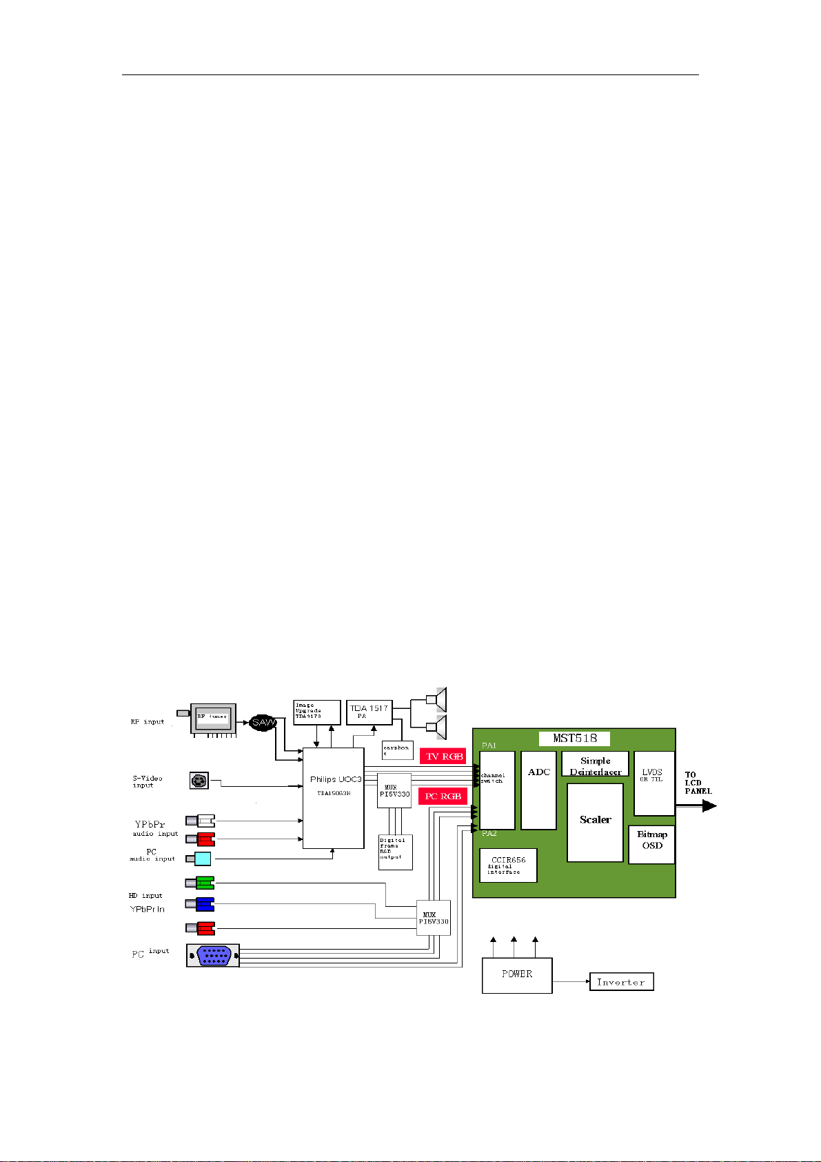
Three Electric circuit of the TV
The Europe LS07 chassis LCD TV is composed of Steady voltage circuit
inverter Circuit RF circuitvideo Strengthen circuitvideo Processing circuit
Power Enlarge circuitVGA circuitsystem control circuit and key control circuit.
the block diagraph of circuit Constitute is below:
Four PCB Module introduction
5

SERVICE MANUAL LS07 chassis
The Constitute of the PCB is easier than LP03 chassis, all the Signal
Processing are in Main board.
1Main board Module
Main board Module is the main part of Signal Processing in LCD TV. The input
signal is Converted into uniform digital signal which can be Identified by LCM by
system control circuit. Main board Module contain two parts of signal
processing Module: Philips UOC3 process analog audio and videoo circuit
mainly, MST518 process VGA circuitsignal Format transform system control
circuit mainly. the front module can convert the video IF signal and audio IF
signal from tuner into RGB analog signal and audio signal, this part is named
analog audio and video decoding process. The RGB color from UOC is
received by MST518 and accomplish A/D convertion , output suitable digital
color signal to Drive circuit of TFT . 8051 Processor inside UOC is responsible
for co-operation the each part of works in system, and Respond to user
operation which is operated on Control panel(key-press panel Module).
2Key board Module
It is composed of 7 function keys. the user can operate the LCD TV
conveniently by using this Module.
3Remote control receiving board Module
It is composed of a work indicator light and a remote receive head. the user use
the remote control box by this module can operate the LCD TV conveniently
and know the LCD TV work condition.
4Earphone output board module
It is composed of a earphone outlet, user can Listen to by earphone
conveniently.
5Inverter board module(include inverter circuit)
The function of the inverter is supply power to light tube in TFT , and lighten
the back lamp Unit of TFT moldule, so the user can see the image on TFT.
Chapter two The function introduction LS07 chassis
LCD TV’s main IC
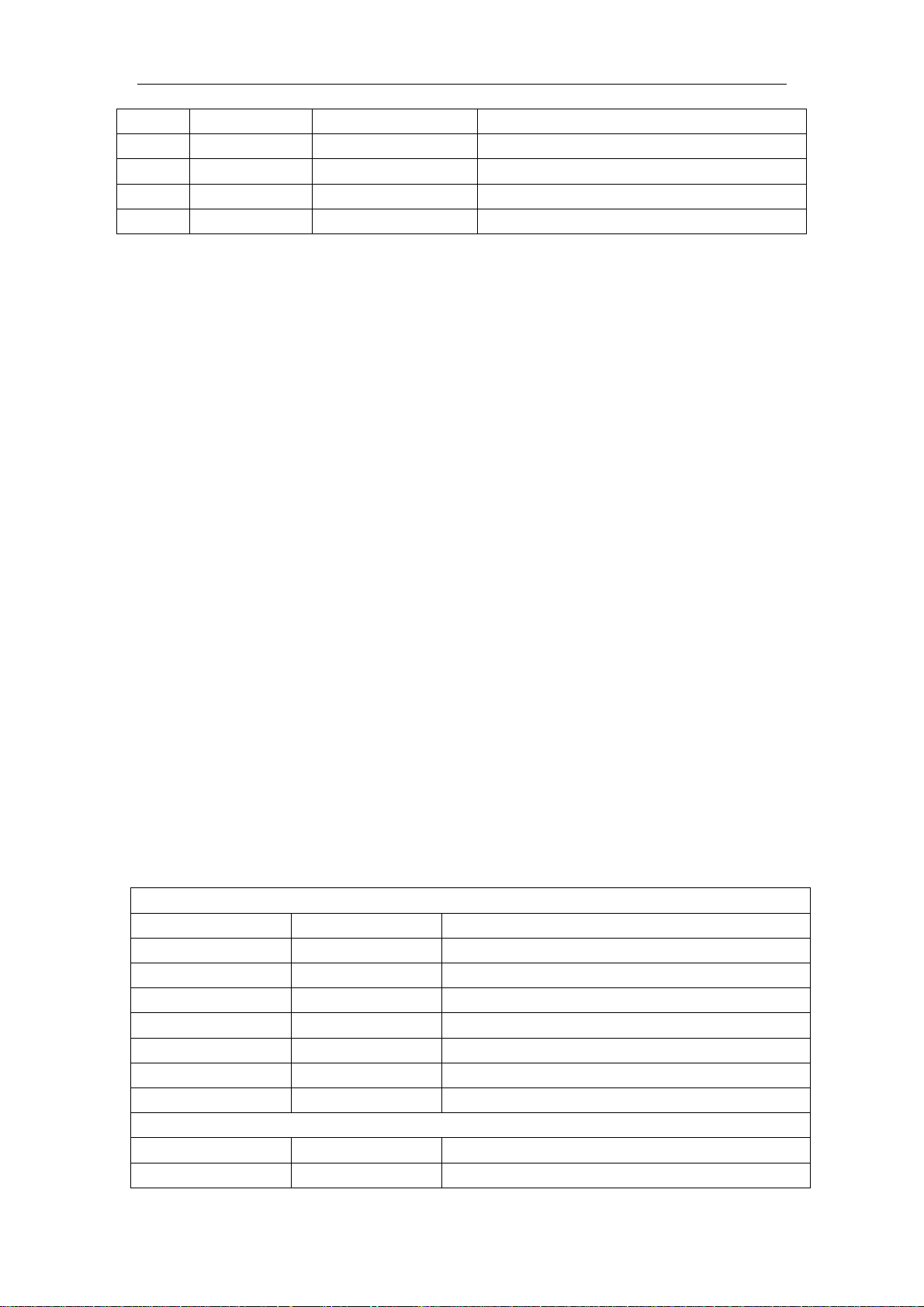
One The main IC of LS07 chassis
serial
number
1 A1 TAF5-C2IP1RW RF tuner
2 U8U21 TDA1517AWT Audio amplifier
3 U3 MST518 AD converter and format change
4 U2 UOC(TDA15063H) Video decode and MCU control
5 Q9 Si2311DS MOS switch
6 U11U12 IRF7316 MOS switch
6
Name model Main function
SERVICE MANUAL LS07 chassis
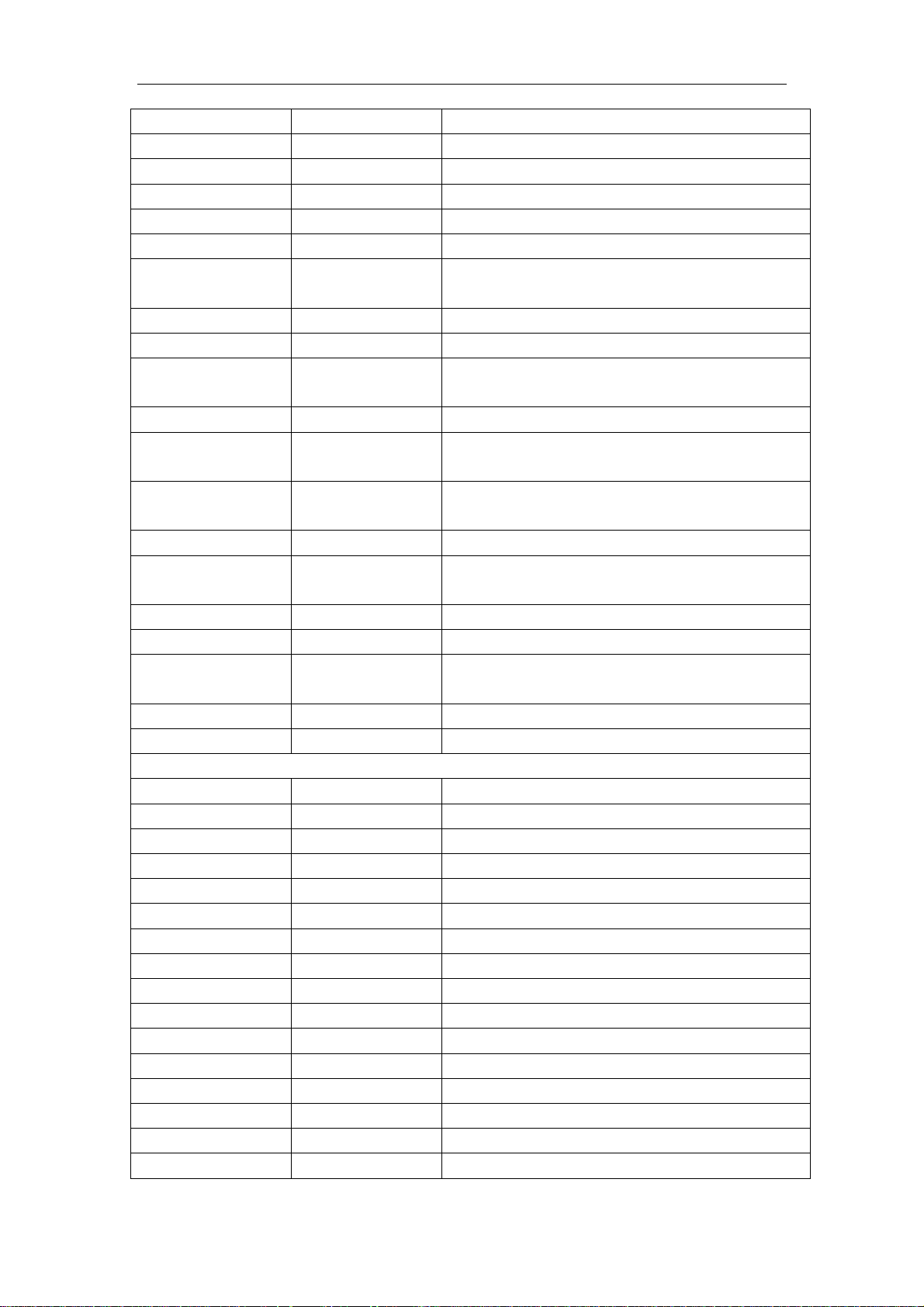
7 U19 NTMS10P02 MOS switch
8 U23 LM2596-5.0 Liner voltage IC
9 U1 24LC21A EEPROM(save display parameter information)
10 U4 24LC32A EEPROMsave user control information
11 U6U20 PI5V330A Video switch
Two The function introduction of main IC
1. MST518 high integration chip
MST518 is a high performancehigh integration image processor which is
designed for LCD, it can support SXGA format(1280*1024).it integrates a group
of AD converter high quality format transform systemOSD generatoroutput
clock generatormultiple format output display interface(support TTLLVDS
RSDS)
MST518 feature:
Have high quality Expand tranform and compress transform, can output XGA
format signal
Integrated LVDS circuit inside
8 bit high quality ADC inside
Double VGA input, Software switch
Support ITU-656 format signal input
Support H/V synccomposite syncgreen composite sync input, and
detect automaticlly by itself
Programmable 10 bit Gamma correct, the brightness and contrast is
adjustable
8 color256 Character OSD
Built-in DDC circuit inside
Low standby power
Support TTLdouble LVDS signal output, Software switch
MST518 pin function:
And CPU interface
Pin Pin name Pin function
33
82
83
84
85
98-91
125
HWRESET
CS
SDA
SCL
INT
AD [7:0]
BUSTYPE
Hardware resethigh voltage enable
Chip select signal of three-wire serial bus
data signal of three-wire serial bus
clock signal of three-wire serial bus
interrupt
Parallel busthe chassis is not used
Bus type select
Analog Interface
38
39
HSYNC0
VSYNC0
Analog Horizontal sync signal input channel 0
Analog vertical sync signal input channel 0
7
SERVICE MANUAL LS07 chassis
40
41
78
79
80
75
74
HSYNC1
VSYNC1
RMID
REFP
REFM
RIN0
RIN0M
Analog Horizontal sync signal input channel 1
Analog vertical sync signal input channel 1
Scaler internal reference. voltage
internal ADC decouple
internal ADC decouple
Analog red signal input channel 0
Analog red signal input channel 0 re.grounding
voltage
73
72
71
SOGIN0
GIN0
GIN0M
Green sync signal input channel 0
Analog green signal input channel 0
Analog green signal input channel 0 re.grounding
voltage
70
69
66
BIN0
BIN0M
RIN1M
Analog blue signal input channel 0
Analog blue signal input channel 0 re.grounding
voltage
Analog red signal input channel 1 re.grounding
voltage
65
64
63
62
61
60
55
RIN1
GIN1M
GIN1
SOGIN1
BIN1M
BIN1
REXT
Analog red signal input channel 1
Analog green signal input channel 1 re.grounding
voltage
Analog green signal input channel 1
Green sync signal input channel 1
Analog blue signal input channel 1 re.grounding
voltage
Analog blue signal input channel 1
Outside connect 390 with 3.3V
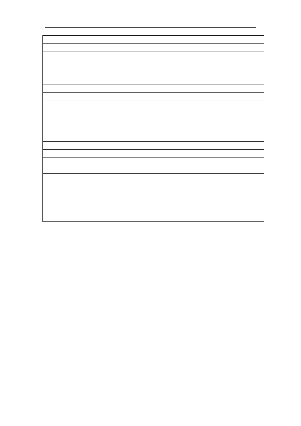
LCD Interface
145 OCLK
146 LDE
144 LVSYNC
143 LHSYNC
138 LVA0M
137 LVA0P
136 LVA1M
135 LVA1P
134 LVA2M
133 LVA2P
128 LVA3M
127 LVA3P
132 LVACKM
131 LVACKP
26-23,18-15 RB[7:0]
14-11, 8-5 GB[7:0]
Clock output
enable signal
vertical sync output
Horizontal sync output
LVDS output 0
LVDS ouput 0+
LVDS output 1
LVDS ouput 1+
LVDS ouput 2
LVDS output 2+
LVDS output 3
LVDS ouput 3+
LVDS clock signal ouput
LVDS clock signal ouput +
TTL red signal channel
TTL green signal channel
8
SERVICE MANUAL LS07 chassis
4,3,154,153,150-147 BB[7:0]
TTL blue signal channel
GPIO Interface
87 GOUT1/PWM1
86 GOUT0/PWM0
2 BYPASS
29 DDC_DAT
30 DDC_CLK
31 DDCROM_CLK
32 DDCROM_DAT
34 XIN
35 XOUT
PWM output 1
PWM output 0
Outside connect filter capacitor
Analog interface DDC data
Analog interface DDC clock
DDC ROM clock
DDC ROM data
Crystal oscillator signal input
Crystal oscillator signal output
Power Pins
48, 54, 58, 77 AVDD
56 AVDD_PLL
36 AVDD_MPLL
10, 22, 88, 99, 111,
129, 139, 151
19, 102, 114, 142 VDDC
1, 9, 20, 21, 37, 42,
45, 51, 57, 59, 76,
81, 89, 100, 101,
112, 113, 130, 140,
141, 152
VDDP
GND
A/D convert power supply
PLL power supply
MPLL power supply
Digital signal output power supply
Digital circuit power supply
Digital circuit ground
2. TDA15063H introduction:
The third-generator super integrated circuit UOC III which designed by
Philips company recently integrates with video decode2D comb filterhigh
quality audio transacting technique, suitable with the European teletext
technique and suitable with US closed caption and V-chip function compatiable
with single series IC. The series of UOC III have high integraty,besides
completing the Processing of all small signal(IF signal demodulation, video
decode ,H/V signal, sound DSP),and integrate all the MCU function. it has
many Advantages ,example: the compact circuitgood performancesimple
craft , ect. it match with company’s high performance price ratio and high
product efficiency demandings. it is suitable for 4:3 or 16:950/60HZ and
A100/120HZ TV system, the main characteristic below:
Multi-system IF demodulationanalog video decode
Comb filter internal
Support 4:316:9 display format
4 CVBS or 3 Y/C input,1 CVBS output,2 YcrCb/2 RGB input
4 AV audio input,1 AV adjustable audio volume output
Volume auto level control circuit
Global FM demodulation
9
SERVICE MANUAL LS07 chassis
Picture quality enhancement of dynamic peak value controlskin color
correctGamma correctBlack level extension,etc
Can turn down horizon and vertical scan partoutput H/V sync. signal to
Scaler
128K Flash Memory inside, support program on line
Automatic Y/C signal identify
TDA15063H pin function:
pin Pin name Pin function
1 VSSP2 Grounding
2 VSSC4 Grounding
3 VDDC4 +1.8V
4 VDDA3 +3.3V
5 VREF_POS_LSL +3.3V
6 VREF_NEG_LSL+HPL 0V
7 VREF_POS_LSR+HPR +3.3V
8 VREF_NEG_HPL+HPR 0V
9 VREF_POS_HPR +3.3V
10 XTALIN crystal oscillator input
11 XTALOUT crystal oscillator output
12 VSSA1 Grounding
13 VGUARD/SWIO Protecting voltage input or I/O
14 DECDIG DECDIG signal input
15 VP1 +5V
16 PH2LF The second grade horizontal phase lock filter
17 PH1LF The first grade horizontal phase lock filter
18 GND1 Grounding
19 SECPLL SECAM PLL decouple
20 DECBG Inside reference voltage decouple
21 EWD/AVL VDD5A voltage input
22 VDRB Tv vertical sync signal output
23 VDRA vertical sync output
24 VIFIN1 VIFinput 1
25 VIFIN2 VIFinput 2
26 VSC Outside connect vertical ramp capacity
27 IREF Re.current input
28 GNDIF IF grounding
29 SIFIN1 SIF input 1
30 SIFIN2 SIF input 2
31 AGCOUT tuner RF AGC control voltage output
32 EHTO overvoltage protection input
33 SSIF MUTE control signal input
34 AUDIOIN5L Av left track signal input
10
 Loading...