

Hyundai DV967S Service Manual

SERVICE MANUAL
DV967S

8.1 HY57V641620HG
32
19
19
34

1.1 GENERAL GUIDELINES
1. SAFETY PREAUTIONS
2.PREVENTION OF ELECTRO STATIC DISCHARGE(ESD)TO
ELECTROSTATICALLY SENSITIVE(ES)DEVICES
1
1. When servicing, observe the original lead dress. if a short circuit is found, replace all parts which have
been overheated or damaged by the short circuit.
2. After servicing, see to it that all the protective devices such as insulation barrier, insulation papers
shields are properly installed.
3. After servicing, make the following leakage current checks to prevent the customer from being exposed
to shock hazards.
Some semiconductor(solid state)devices can be damaged easily by static electricity. Such components
commonly are called Electrostatically Sensitive(ES)Devices. Examples of typical ES devices are integrated
circuits and some field-effect transistors and semiconductor chip components. The following techniques
should be used to help reduce the incidence of component damage caused by electro static discharge(ESD).
1. Immediately before handling any semiconductor component or semiconductor-equipped assembly, drain
off any ESD on your body by touching a known earth ground. Alternatively, obtain and wear a commercially
availabel discharging ESD wrist strap, which should be removed for potential shock reasons prior to
applying power to the unit under test.
2. After removing an electrical assembly equipped with ES devices,place the assembly on a conductive
surface such as alminum foil, to prevent electrostatic charge buildup or exposure of the assembly.
3. Use only a grounded-tip soldering iron to solder or unsolder ES devices.
4. Use only an anti-static solder removal device. Some solder removal devices not classified as anti-static
(ESD protected)can generate electrical charge sufficient to damage ES devices.
5. Do not use freon-propelled chemicals. These can generate electrical charges sufficient to damage ES
devices.
6. Do not remove a replacement ES device from its protective package until immediately before you are
ready to install it. (Most replacement ES devices are packaged with leads electrically shorted together by
conductive foam, alminum foil or comparable conductive material).
7. Immediately before removing the protective material from the leads of a replacement ES device, touch
the protective material to the chassis or circuit assembly into which the device will be installed.
Caution
Be sure no power is applied to the chassis or circuit, and observe all other safety precautions.
8. Minimize bodily motions when handling unpackaged replacement ES devices. (Otherwise harmless motion
such as the brushing together of your clothes fabric or the lifting of your foot from a carpeted floor can
generate static electricity(ESD).
notice (1885x323x2 tiff)

2

The laser diode in the traverse unit (optical pickup)may brake down due to static electricity of clothes or human
body. Use due caution to electrostatic breakdown when servicing and handling the laser diode.
Some devices such as the DVD player use the optical pickup(laser diode)and the optical pickup will be damaged
by static electricity in the working environment.Proceed servicing works under the working environment where
1. Put a conductive material(sheet)or iron sheet on the area where the optical pickup is placed,and ground the
3. The flexible cable may be cut off if an excessive force is applied to it.Use caution when handling the cable.
3
4.PREVENTION OF STATIC ELECTRICITY DISCHARGE
4.1.Grounding for electrostatic breakdown prevention
grounding works is completed.
4.1.1. Worktable grounding
sheet.
4.1.2.Human body grounding
1 Use the anti-static wrist strap to discharge the static electricity from your body.
safety_3 (1577x409x2 tiff)
4.1.3.Handling of optical pickup
1. To keep the good quality of the optical pickup maintenance parts during transportation and before
installation, the both ends of the laser diode are short-circuited.After replacing the parts with new ones,
remove the short circuit according to the correct procedure. (See this Technical Guide).
2. Do not use a tester to check the laser diode for the optical pickup .Failure to do so willdamage the laser
diode due to the power supply in the tester.
4.2. Handling precautions for Traverse Unit (Optical Pickup)
1. Do not give a considerable shock to the traverse unit(optical pickup)as it has an extremely high-precise
structure.
2. When replacing the optical pickup, install the flexible cable and cut is short land with a nipper. See the
optical pickup replacement procedure in this Technical Guide. Before replacing the traverse unit, remove
the short pin for preventingstatic electricity and install a new unit.Connect the connector as short times as
possible.
4. The half-fixed resistor for laser power adjustment cannot be adjusted. Do not turn the resistor.
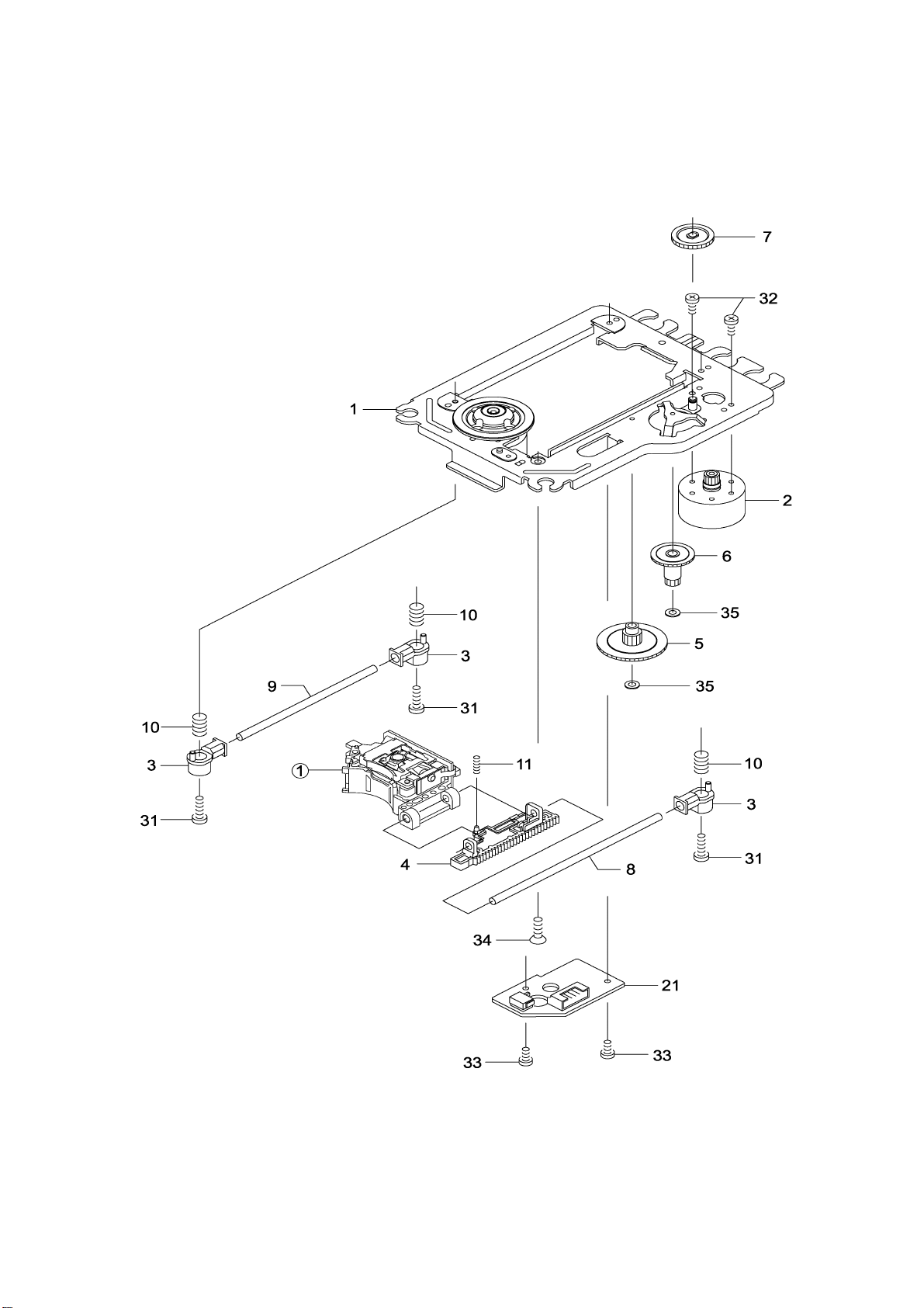
5.1 Optical pickup Unit Explosed View and Part List
5. Assembling and disassembling the mechanism unit
4
Pic (1)

Materials to Pic (1)
5
No. PARTS CODE PARTS NAME Q ty
14692200 SF-HD60 1
1
1EA0311A06300 ASSY, CHASSIS, COMPLETE 1
2
Or
3
4
5
6
7
8
9
10
11
21
Or
31
32
1EA0M10A15500 ASSY, MOTOR, SLED 1
1EA0M10A15501 ASSY, MOTOR, SLED 1
1EA2451A24700 HOLDER, SHAFT 3
1EA2511A29100 GEAR, RACK 1
1EA2511A29200 GEAR, DRIVE 1
1EA2511A29300 GEAR, MIDDLE, A 1
1EA2511A29400 GEAR, MIDDLE, B 1
1EA2744A03000 SHAFT, SLIDE 1
1EA2744A03100 SHAFT, SLIDE, SUB 1
1EA2812A15300 SPRING, COMP, TYOUSEI 3
1EA2812A15400 SPRING, COMP, RACK 1
1EA0B10B20100 ASSY, PWB 1
1EA0B10B20200 ASSY, PWB 1
SEXEA25700--- SPECIAL SCREW BIN+-M2X11 3
SEXEA25900--- SPECIAL SCREW M1.7X2.2 2
33
34
35
Note : This parts list is not for service parts supply.
SFBPN204R0SE- SCR S-TPG PAN 2X4 2
SFSFN266R0SE- SCR S-TPG FLT 2.6X6 1
SWXEA15400--- SPECIAL WASHER 1.8X4 X0.25 2

5.2 Bracket Explosed View and Part List
6
Pic (2)
Materials to Pic(2)
1.bracket 14. front silicon rubber
2.belt 15. Back silicon rubber
3.screw 16. Pick-up
4.belt wheel 17. Pick-up
5.gearwheel 18. switch
6.iron chip 19. Five-pin flat plug
7. Immobility mechanism equipment 20. screw
8. Magnet 21. PCB
9. Platen 22. motor
10. Bridge bracket 23. Motor wheel
11. screw 24. screw
12. screw 25.tray
13. Big bracket
Before going process with disassembly and installation, please carefully both
peruse the chart and confirm the materials.

5.3 MISCELLANEOUS
7
5.3.1 Protection of the LD(Laser diode)
Short the parts of LD circuit pattern by soldering.
5.3.2 Cautions on assembly and adjustment
Make sure that the workbenches,jigs,tips,tips of soldering irons and measuring instruments are
grounded,and that personnel wear wrist straps for ground.
Open the LD short lands quickly with a soldering iron after a circuit is connected.
Keep the power source of the pick-up protected from internal and external sources of electrical
noise.
Refrain from operation and storage in atmospheres containing corrosive gases (such as H2S,SO2,
NO2 and Cl2)or toxic gases or in locations containing substances(especially from the organic silicon,cyan,
formalin and phenol groups)which emit toxic gases.It is particularly important to ensure that none of the
above substances are present inside the unit.Otherwise,the motor may no longer run.

6.1. Video Output (Luminance Signal) Confirmation
6.Electrical Confirmation
8
DO this confirmation after replacing a P.C.B.
Measurement point
Video output terminal
Measuring equipment,tools
200mV/dir,10 sec/dir
Purpose:To maintain video signal output compatibility.
1.Connect the oscilloscope to the video output terminal and terminate at 75 ohms.
2.Confirm that luminance signal(Y+S)level is 1000mVp-p±30mV
PLAY(Title 46):DVDT-S15
PLAY(Title 12):DVDT-S01
Mode Disc
Color bar 75%
Confirmation value
1000mVp-p±30mV
DVDT-S15
or
DVDT-S01

Do the confirmation after replacing P.C.B.
Screwdriver,Oscilloscope
6.2 Video Output(Chrominance Signal) Confirmation
9
Measurement point
Video output terminal
Measuring equipment,tools Confirmation value
200mV/dir,10 sec/dir
Purpose:To maintain video signal output compatibility.
1.Connect the oscilloscope to the video output terminal and terminate at 75 ohme.
2.Confirm that the chrominance signal(C)level is 621 mVp-p±30mV
PLAY(Title 46):DVDT-S15
PLAY(Title 12):DVDT-S01
Mode Disc
Color bar 75%
621mVp-p±30mV
DVDT-S15
or
DVDT-S01

7.MPEG BOARD CHECK WAVEFORM
7.1 27MHz WAVEFORM
7.2 IC NCP1200 PIN.5 WAVEFORM DIAGRAM
10

16 Megabit (2 M x 8-Bit/1 M x 16-Bit)
11
8. Am29LV160D
CMOS 3.0 Volt-only Boot Sector Flash Memory
DISTINCTIVE CHARACTERISTICS
■ Single power supply operation
— Full voltage range: 2.7 to 3.6 volt read and write
operations for battery-powered applications
— Regulated voltage range: 3. 0 to 3.6 volt read and
write operations and for compatibility with high
performance 3.3 volt microprocessors
■ Embedded Algorithms
— Embedded Erase algorithm automatically
preprograms and erases the entire chip or any
combination of designated sectors
— Embedded Program algorithm automatically
writes and verifies data at specified addresses
■ Manufactured on 0.23 µm process technology
— Fully compatible with 0.32 µm Am29L V160B device
■ High performance
— Access times as fast as 70 ns
■ Ultra low power consumption (typical values at
5MHz)
— 200 nA Automatic Sleep mode current
— 200 nA standby mode current
— 9 mA read current
— 20 mA program/erase current
■ Flexible sector arc hitecture
— O ne 16 Kbyte, two 8 Kbyte, one 32 Kbyte, and
thirty-one 64 Kbyte sectors (byte mode)
— One 8 Kword, two 4 Kword, one 16 Kword, and
thirty-one 32 Kword sectors (word mode)
— Supports full chip erase
— Sector Protection features:
A hardware method of locking a sector to prevent
any program or erase operations within that sector
Sectors can be locked in-system or via
programming equipment
Temporary Sector Unprotect f eature allows code
changes in previously locked sectors
■ Unlock Bypass Program Command
— Reduces overall pr ogramming time when issuing
multiple program command sequences
■ Top or bottom boot block configurations
available
■ Minimum 1,000,000 write cycle guarantee
per sector
■ 20-year data retention at 125°C
— Reliable operation for the life of the system
■ Package option
— 48-ball FBGA
— 48-pin TSOP
— 44-pin SO
■ CFI (Common Flash Interface) compliant
— Provides device-specific information to the
system, allowing host software to easily
reconfigure for different Flash devices
■ Compatibility with JEDEC standards
— Pinout and software compatible with single-
power supply Flash
— Superior inadvertent write protection
■ Data# Polling and toggle bits
— Provides a software method of detec ting program
or erase operation completion
■ Ready/Busy# pin (RY/ BY#)
— Provides a hardware method of detecting
program or erase cycle completi on (not av ailable
on 44-pin SO)
■ Erase Suspend/Erase Resume
— Suspends an erase operation t o read data from,
or program data to, a sector that is not being
erased, then resumes the erase operation
■ Hardware reset pin (RESET#)
— Hardware method to reset the devic e to reading
array data
This Data Sheet states AMD’s current technical specifications regarding the Product described herein. This Data
Sheet may be revised by subsequent versions or modificat ions due to changes in technical specif ic ations.
Publication# 22358 Rev: B Amendment/+3
Issue Date: November 10, 2000
 Loading...