


This two-element, tri-band quad operates on 10, 15,
ground and hoist it
position as sho
and 20 meters. The choice to two band settings:
phone and CW, presents low VSWR across each
segment with broadband characteristics.
Heavy swaged aluminum tubing speraders offer
strength and durability, and are free of pattern
distortion effects. The spreaders are broken at
strategic electrical points with high impact-cycolac
insulators and are completely free of "RF" an d pattern
The Driven Element is at DC ground to eliminate
static noise and to provide lightning protection .
Separate pretuned gamma matches offer isolation.
The closed loop feature decreases static build-up.
Taper swaged tubing and vertix-feed combine to
provide mechanical stability. Th e cast alu minum tilthead boom gives strength and offers a choice of mast
diameters.
The preset speader arms are drilled for easy
assembly. You only need to measure the element
One transmission line feeds all thre e bands. RG-8/au
offers minimum cable loss and full legal power
capabilities. If your cable run is less than 60 feet and
power doesn't exceed 200 watts use RG-58/au.
Decide the best height for your installation . Heigh t
above the ground determines the angle of radiation
(the lower the angle, the greater the range).
For best results, install the Hy-Qu ad at least 45 feet
above the ground and 8 to 10 feet above your tower
or rotator.
The site should be clear of any objects of a large,
conductive mass which tend to sh ift an tenna
resonance, affect the VSWR, and distort the radiation.
NOTE: To prolong the life of this product in or aroun d
coastal areas, it is recommended that all hardw are be
encapsulated with a silicone rubber compoun d such
as Dow-Corning silastic rubber or GE silicon e sea l to
prevent atmospheric deterioration.
Electrical
Input impedance (nominal)…………………52 ohms
Forward gain… 10 meters -8.7 dB; 15 meters -8.5 dB;
20 meters -8.3 dB
Front-to-back ratio …………………… 25 to 35 dB
depending on electrical height
Maximum power input ……………….. 1 kw AM, 4 kw
P.E.P VSWR at resonance ................ 1.5:1 or better
Lightning protection .................... DC ground
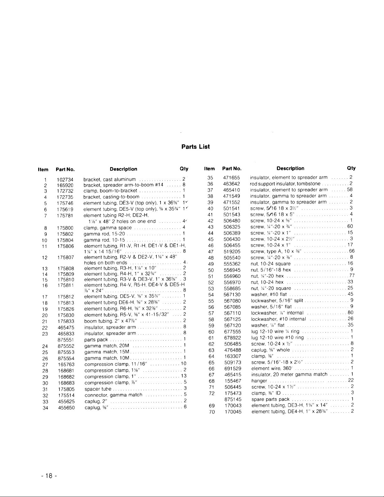
Study the manual and familiarize yourself with the
NOTE: When unpacking
of all
inside
smaller
articles are sometimes put
tubing
tubing
etc.). To conserve space, these smaller
your antenna,
check the
for parts (clamps, insulators,
the larger pieces.
inside
NOTE: All tubing supplied with the Hy-Quad is
designed to telescope together. It is held in place with
two #10 x
3
self-tapping screws. All tubing lengths
/8"
are predrilled for your convenience. For optimu m
operation, all element-to-wire dimension s should be
followed by ±
1/8"
.
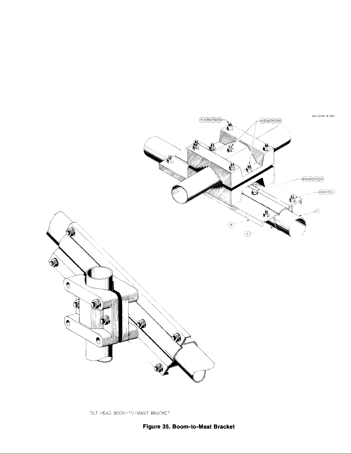
The size of this antenna requires consideration as to
how you are going to get it to the top of your tower.
The tilt-head boom-to-mast bracket (see Figure 35)
facilitates assembly of the an tenna in halv es. Th ere
are two installation methods :
Method 1 - Completely assemble the antenn a on the
into
wn in Figure 1.
Method 2 - Assemble the antenna on the groun d in
halves, then hoist each half up the tower and attach
to the boom-to-mast bracket on th e tower.
The best method is to assemble the antenna in halv es
on the ground. When this is done the reflector and
driven element spreaders must be in the same plane.
Attach the boom to the boom-to-mast br acket an d
assemble the sperader arm to boom bracket on the
boom. MAKE SURE THE DRIVEN ELEMENT AND
REFLECTOR BRAC K ETS A RE IN THE SA ME PLAN E. Now
separate the antenna in halves and complete th e


e. Driven Element Spreader Arm Assembly Horizontal
1
5
y
p
g
f. Assembly of Spreader Arms to Boom Sections
g. Compression Clamp
Assembly h. Element Ass embly
i. Phone By-Pass
Wires j. Element
Tension
k. Gamma Match
Assembly I. Boom
Horizontal
( ) Both ends of the horizontal spreader arms are
assembled in exactl y the same way. For s im plicit y, the
assembly procedures for only one end will be
( ) Insert the 1
tube. Align the hol es and secure the tubes using #10
3
x
self tapping screws.
/8"
x 48" tube into the
/8"
1'/4"
x 14'
/6"
( ) Select the spreader arm insulators and attach them
loosel
on the end of the
( ) Select the tube measuring 1
into the s
reader arm insulator.
1 1/8"
x 48" tube.
x 10" and insert it
1/8"
The assembly sequence will be described in the
following order:
a. Reflector Spreader Arm Assembly Horizontal
b. Reflector Spreader Arm Assembly Vertical
c. Driven Element Spreader Arm Assembly Top
Vertical d. Driven Element Spreader Arm Assembly
Bottom Vertical
CAUTION
The 10" piece
that allows a 2" space bet ween it and the
depth
48"
length of 1
of 1
1
1
tube must be inserted to a
/8"
tube. Once this 2"spacing
/8"
dimension is assured, securely
insulator sections to
ether using the 1/4" x 3/4"
tighten
the

This concludes the assembly of half the horizontal
pping
reflector spreader arm. The other half is assembled in
exactly the same way.
Vertical
( ) Select a 1'/4" x 14'
5
/6' tube and a
x 48" tube.
1'/8"
Do not interc hange the ends. The ho le diameters are
different and the small holes must be inside the large
tubes. Align the holes and secure the tubes using #10
( ) Select the 1 " x 36
the smaller drilled holes into the
the holes an d secur e usin g #10 x
( ) Select the
%e"
end into the 1 " x 36
secure with #10 x
() Select the
end into the
%8"
using the #10 x
5
tubes and slip the end with
/8"
x 48" tubes. Align
1'/8"
self tapping
3/8"
x 24" tubes and slip the unswaged
5
tubes. Align the holes and
/8"
self tapping screws.
3/8"
5
x 41'5/2' tubes and slip the drilled
/8"
x 24" tubes. Align the holes and secure
3
self tapping screws.
/8"
Driven Elemen t
Top Vertical Spre ader Arm
Refer to Figure 4. Select a 1'/4" x 14'
x 48" tube. Slip the
/8"
x 48" tube into the end of
1'/8"
5
tube and a 1'
/,6"
the 1'/4" tube. Align the holes and secure using the
( ) Select a 1 " x 32
3
tube and s lip t he en d w ith the
/4"
smaller drilled holes into the 10" piece of 1
Align the holes and secure using the #10 x
ta
( ) Select the
smaller holes into the 1 " x 32
and secure using #10 x
( ) Select the
into the
using the #10 x
screws.
x24" tu be an d sl ip t he en d w ith
%e"
5
/8"
x 24" tube. Align the holes and secure
%e"
3
x 32
/8"
self tapping screws.
3/8"
3
tube. Align the holes
/4"
self tapping sc rews.
3/6"
tube and slip the drilled end
-
1/8"
3
/8"
tube.
self
( ) Next, select the 1 " x 36
5
tube, which is drilled for
/8"
attachment of a tombstone insulator, and insert into
the
#10 x
() Select the
36
( ) Next, select the
x 48" tube. Align the holes an d secure us ing
1'/8"
self tapping scr ews.
3/8"
x 24" tube and insert into the 1 " x
5
tube. Align the holes and secure using #10 x
/8"
%e"
5
/8"
x 35
3
tube, which is also
/4"
drilled for attachment of the tombstone insulator, and
insert into the
holes line up. The hole for the tombstone insulator in
5
this
tube must line up with the tombstone insulator
/8"
hole in the 1 " x 36
x 24" tu be . Tur n th e tu be so the
%8"
5
tube.
/8"
( ) This completes assembly instructions on the top
driven element assembly. This should now be marked
"Top DE" and set aside for future use.
Bottom Vertical Spreader Arm
( ) First, select the
1'/4"
tube, Insert the drilled end of
the drilled end of the 1'/4
( ) Select the 1 " x 36
end into the 1
1
5
tube. Align the holes and fasten
/8"
secur e ly , using t h e # 1 0 x
5
x 14'
tube and insert the drilled
/8"
3/e"
tube and a
/,6"
diameter tube into
1'/8"
"
diameter tube. Align the
self tappin g scr ews.
1'/8"
x 48"
Align the holes and fasten securely.
3
/8"

( ) Select the 78" x 24" tube and insert it into the 1 " x
g
"
5
y
y
p
g
p
g
g
3
g
g
/
5
g
y
y
(
g
y
5/8"
36
tube. Align the holes and secure using #10 x
( ) Finally, select the 5/8" x 353/4" tube and insert in the
"
78
tube. Again, ali gn th e ho le s and faste n secu rely
usin
the same type hardware as before.
3
/8"
( ) Mark this spreader arm assembly "Lower DE" and
Horizontal Spreader Arm Assembly
The last spreader arm ass embly is the hor izontal arm s
of the driven element. These to o will be assem bled in
halves. Both halves are identical, therefore, assembly
( ) Select the 1'/4
Insert the end of the 11/8" x 48"tube into the drilled end
1'/4"
of the
securel
using the #10 x 3/8" self tapping screw.
x 14'
5
/,6"
/,6"
x 14'
tube and 1'/8" x 48" tu be .
tube. Align the holes and fasten
( ) Select the spreader arm insulators and attach
loosel
on the end of the 11/8" x 48" tube.
( ) Select the tube measuring 11/8" x 14" and insert into
the s
reader arm insulator.
Fi
ure 5. Spreader Arms Grouped and Labeled
NOTE: To aid in this part of the assembly, a 3" dia. x 3'
length of pipe can be driven in the ground about 1 foot.
This will hold each boom section in a near vertical
osition while the spreader arms are assembled.
( ) Select the eight spreader element brackets and
loosely assemble using '/4-20 x
3/4"
bolts, nuts, and
lockwashers, '/4"-20 x V anchor bolts and square nuts,
as shown in Fi
ure 6.
CAUTION
The 14" piece of 1
depth leaving a 2" space between it an d the 48"
length of 1
dimension is assured, securely tighten the
insulator sections together, using the
( ) Select the 1" x 28
1
/8" tube m ust be inserted to a
1
/8" tube. Once this 2" spacing
1
/4" x 3/4"
/4" tube and slip the en d wi th th e
smaller holes into the 14" piece of 1'/8" tube. Align the
holes and secure usin
( ) Select the 78" x 24" tube and slip the end with the
smaller drilled holes into the 1 " x 28
holes and secure usin
( ) Select the
into the 78
usin
#10 x
/8" x 283/8" tube and slip the drilled end
"
x 24" tube. Align th e ho les and se cure
3/a"
self tapping screws.
#10 x 3/8" self tapping screws.
3
/4" tube. Align the
3
#10 x
8"
self tapping screws.
( )This complete s the a ssembly of half the horiz ont al
driven element spreader arm. The other half is
assembled in exactl
the same way.
( ) Select a 2" x 4778" of tubing and stick the end with
5
the
/16" dia. hole into the piece of 3" pipe driven in the
round previously. This is one half of the boom.
ure 6. Boom-to-spreader Arm Assembl
Fi
Assembl
of Spreader Arms To Boom Sections:
( ) Place two pair of loosely assembled spreader
( ) At this point, 8 spreader arms should be properly
labeled and grouped together as to Reflector or Driven
Element
four in each group) as shown in Figure 5.
element brackets in position on the end of the boom as
shown in Figure 7. Place the 2" caplugs on the ends of

( ) Select the remaining 2" x
pip
p
y
e end of each bracket, as sho
above
g
p
( )
3
(
)
p
1
insert the drilled end into the
47%8"
boom section and
e as done before.
( ) Select the last 2 pair of loosely assembled boomtospreader arm brackets and assemble them on the
7.
opposite and of the boom, as shown in Figure
Leave
just enough room for the 2" caplug to be inserted on
the end of the boom tube as shown.
( ) Insert the four remaining spreader arm insulators
into the ends of each
air of brackets.
( ) From the group of driven element spreader arms,
select the one marked Driven Element Top and the
Figure 7. Boom-to-spreader Arm Bracket Assembl
( ) Select 4 spreader arm insulators and insert one into
th
wn
.
( ) From the group of reflector spreader arms
assembled earlier, take the two marked horizontal
and slip them into the two spreader arm insulators in
the brackets farthest from the end of the boom See
( ) From the same group, take the two spreader arms
marked top and bottom reflector and insert them into
the other pair of brackets assembled closest to the
( ) Insert these into each end of the spreader arm
insulators on the bracket farthest from the top end of
( ) Turn the driven element top spreader arm so that
when the boom section is standing vertical the extra
holes in the 1 " and
5/8"
tubes of this spreader arm
assembly are pointing straight up.
NOTE: To avoid problems later in the assembly, be
sure that all the tubes bottom out a
ainst the insulator.
( ) Select the two remaining spreader arms marked
( ) Insert these into the spreader arm insulators
located in the
Tighten the
air of brackets closest to the end cap.
'/4"
/4"
x
bolts securely.
( ) Adjust the spreader arms to 90° apart by slowly
turning the boom-to-spreader arm brackets, then
tightening the
'/4" x 3/8"
anchor screws located on each
Figure 8. Boom-to-spreader Arm Bracket
NOTE: The spreader arm bracket containing the
horizontal spreader arms should be parallel with the
5
/,5"
diameter hole in the opposite end of the 2" boom
( ) Remove this assembly from the pipe and prepare
to assemble the driven element spreader arms on the
other 2" x
-8
47%8"
boom section.
( ) This completes the driven element half of the
NOTE: Make sure the horizontal spreaders are
parallel with the
5
/s"
diameter hole in the opposite end
"
Compression Clamp Assembly
See Figures 10, 11, and 12
Driven Element
NOTE: Com
( ) Slip the two 1
over the ends of the horizonal element spreader tubes
and assemble them in their proper position on the 1
ression clamps should only be hand
/8"
compression clamps, item 28,
1
/8"

( ) Install the six 1" compression clamps, item 29. Slip
,
g
g
5
p
g
p
g
p
g
p
y
three of them over the bottom vertical driven element
spreader arm as shown in Figure 9. Slip one over the
top end of the vertical spreader arm as shown and
slip one over each end of the driven element
horizontal spreader arm as shown in Figure 9.
( ) For proper assembly of the middle 1 " compression
clamp on the middle of the bottom driven element
tube
refer to Figure 24, Gamma Match Detail.
( ) Select two %a" compression clamps, item 30, and
slip one on the end of each vertical driven element
spreader arm and loosely attach them on the %a"
tubin
at the dimensions called for in Figure 9.
( ) Next, select five of the "/16" compression clamps
and place them on each spreader arm at the locations
shown'in Fi
ure 9.
NOTE: The
/8" tube of the bottom vertical driven
element spreader arm takes two "/16" compression
clam
s as shown.
( ) This completes the basic assembly of the
compression clamps on the driven element half of the
antenna. Remove this half from the pipe and lay it to
( ) Insert the reflector half of the antenna in the pipe
and prepare to assemble the compression clamps as
shown in Fi
ure 13.
( ) Select seven 1 " compression clamps and
hardware. Slip two clamps on each end of the
horizontal reflector spreader arms, two clamps on the
bottom vertical reflector spreader arms and one clamp
on the to
vertical reflector spreader arm.
( ) Loosely assemble these clamps at the location
iven in Figure 13.
( ) Select three 7/8 " compression clamps and
hardware. Slip two clamps over the bottom vertical
reflector spreader arms and one clamp over the top
vertical reflector s
reader arm.
( ) Move them to the proper dimensions shown in
Fi
ure 13 and fasten loosely.
( ) Select five' /,
compression cl amps and hardware
s"
and slip two clamps on the e nd of the bottom vertical
reflector s
reader arm as shown in Figure 13.
( ) Slip one clamp on each of the other reflector
spreader arms. Fasten all five compression clamps
loosel
at the locations shown in Figure 13.


1. Measurements are made from the center of
pping
y
pping
g
g
y
g
g
g
compression clamps and the center of hole in
insulators. Tolerances are not specific: antenna
performance depends on assembly.
2. Add 2112' to this dimension for overall length of the
wire to allow for wra
and bypass loops.
ure 14. Measurements For Antenna Stringin
Fi
3. Length of the loop must be maintained at 9". All
other bypass wire dimensions are found in det ai led
assembl
4. Add 1 1/2' to this dimension for overall length of wire
to allow for wra
illustrations. Keep all dimensions accurate.
and bypass loop.
IMPORTANT
The
most difficult part of
the
antenna assembly
is the stringing of the element wire. Take extra
time to plan the remaining steps. Figure 14
NOTE: Dimensions of jumper wires are critical. All
The element wire shrinks in cold weather, DO NOT
hten it during assembly.
overti
gives the lengths and spacings of the elements.
NOTE: To prevent tangling, do not cut all wires ties
holding the large roll of wire. Improvise a spool or
General Assembly Outline
The general outline of steps is listed below. Follow the
detailed instructions for assembl
1. Attach all insulators to the compression clamp
2. Strin
3. Attach all jumper wires, i.e. phone bypass, driven
element bypass etc. as shown in the detailed
drawings, Figure 16 through Figure 34.
the element wires.
.
some other means of containment and pull off only as
much wire as needed for each piece. Do not use pliers
to pull or wrap the wire. Any nicks weaken the wire.
Detailed Assem b ly Instructions
( ) Mount the element insulator hangers, item 68, on
the element tubes. The locations for the driven
element spreader arms are noted in Figure 15. Their
typical mounting is shown in Figures 16, 17, 21, 22,
and 23. Refer to Fi
ure 34 for more detail.

( ) Squeeze the hanger ends together so the
p
g
'
( ) Assemble the ten and fifteen meter driven element
upper insulators as shown in Figure 18, 19 and 20,
and attach to the to
( ) Fasten the compression clamps securely at the
dimensions shown in Fi
driven element spreader arm.
ure 13.

NOTE: These figures are only to be used for proper
bottom d
eader a
ging
assembly of the hangers and insulators on the
various compression clamps and should not be used
at this time for attaching element wire. This phase of
assembly will be explained later.
( ) Refer to Figure 24 for attaching hardware to the
riven element spr
Strin
( ) Cut two lengths of wire to the dimen sions giv en in
Figure 14. String them individually from the left
spreader arm through the insula tors on the top
spreader arm, and down to the right spreader arm.
NOTE: Cut the wires 2'-6" longer th an specified to
allow for loops and wrapping at each end but mark
the specified lengths with tape.
( ) All remaining wires on the driven element can be
strung in halves. This is don e by adding the
dimensions together, cuttin g th e wire and then
stringing. Example: Driven Element, 10 Meter.
Combining the two dimensions shown in Figure 14
(left spreader-to-top spreader and right spreader-totop spreader) you have 16' 3". Add 2'6" to this
dimension for excess to be used for the loops and
Element
rm.
( ) Use the same procedure on the bottom half of the
10 Meter driven element wire and splice the two
halves together with a Western Union Splice (Figure
21), making sure the splicing loop length is 9". Clip
off all excess wire when the antenna is completely
strung. Use this procedure at all the remaining points
within the antenna.
( ) Connect the fifteen meter wire on the driven
element spreader arms as shown in Figures 18, 22
and 24. The jumper wire in Figure 18 presents wire
slippage, tie it as short as possible.
( ) Connect the ten meter wire on the driven element
spreader arms as shown in Figure 19, 23 and 24.
Refer to these figures and Figure 14 for aid in this
part of the assembly. The jumper wire in Figure 19
presents wire slippage - tie it as short as possible.
( ) Beginning with the 20 meter wire on the left
spreader insulator, Figure 21, wrap and tie the wire
through the insulator leav ing enough wir e for
splicing. The loop length with splice mus t be 9". Run
the wire through the insulator on the top sprea der
arm, Figure 16, and connect it to the insula tor on th e
right spreader arm as shown in Figure 21, only
reversed. Your lengths must correspond to the

NOTES
1. Same general arrangement as in Detail "A". 2. Use a
flat washer on each side of wire. 3. Center conductor of
coax connects to 10 meter gamma match, braid
connects to compression clamp screws.


( ) Cut the wire as was done with the driven element.
gth,
g
g
p
p
y
g
pp
p
Use Figure 14 as a guide. Double the dimension and
add 2'6". Cut the wire. When stringing and attaching
the 20 meter element wire, refer to Figures 26, 28, and
33. Note that Figure 26 shows the left horizontal
spreader arm attachment. The right horizontal
spreader arm attaches to the element wire the same
as the left. Therefore, Figure 26 will be used as a
guide for both horizontal connections of the 20 meter
( ) The 15 meter wire should be cut by referring to
Figure 14 for the dimensions, then doubling the
len
add 2' 6" for loops and splices, and cut.
( ) Refer to Figures 27 and 29 for connecting the top
( ) Refer to Figures 27 and 32 for connecting the
bottom half of the 15 meter wire. Again, the left and
right horizontal connecti ons are ident ic al as sho wn in
Figure 27, and referred to the Figure 25. The loop
len
th with splice must be 9", as shown in Figure 34.
( ) Connect the wires using a Western Union splice, as
done before. The lengths must correspond to the
dimensions shown in Fi
ure 14.
NOTE: When stringing the wires, do not wrap the wire
around the compression clamp screws. Pass the
wires by the screws and wrap around the hanger.
Remember the wire wra
( ) Refer to Figure 25 for a general diagram of how
wire should look on the reflector half of the antenna. 14
ed on the hanger is shorted
( ) Refer to Figures 27 and 30 for connecting the top
half of the 10 meter wire to the reflector s
( ) Figure 27 and 31 give detailed instructions as to
the proper connection of the bottom half of the
( ) Connect the ends with the Western Union splice.
Kee
the 9" loop dimension accurate. Referto Figure
Phone B
For operation on the phone frequencies, the phone
bypass wires should be installed exactly as shown in
Fi
ures 16 and 19 and in Figures 31, 32 and 33.
( ) Driven Element: Tension the driven element by
loosening the compression clamps on the top, right
and left spreader arms and moving the clamps out
( ) Tension and remove the kinks from the wires, but
do not over tension them. There should be some slack
in the wire to
( ) Reflector: Tension the reflector by loosening the
compression clamp screws on the top and bottom
spreader arms and moving the clamps out toward the
ends of the arms. The wire should not be wrapped
around these screws. Pull the wires taut, move the
clamps out, secure the clamp and tighten the nuts.
revent the spreader arms from bowing.
-Pass Wires
reader


( ) Moving the compression clamps out on the
y
g
spreader arms will create an error when compared to
the dimensions in Figures 9 and 13. These are
approximate positioning dimensions and may not
meet at the end of the antenna assembly. The critical
dimensions are the lengths of the element loops, as
shown in Figure 14.
( ) Upon completion of the assembly, each leg of the
antenna loop should be accurate to within
±1/4"
(Figure
14) and '/z of the element loop should be within +/1/2". Example: 10 Meter, Driven Elem ent. Each
dimensions of 8' 1 1/2" to within
±1/4"
and 16' 3" to
NOTE: If you want best performance for the phone
sections of the amateur bands, the element by-pass
wires should be installed now. See the detailed
illustrations.
Gamma Match Assembl
( ) Select the gamma match clamps and hardware
and install them on the
amma matches. See Figure
( ) Attach the gamma matches to the element wires.
When you have the correct spacings on the gamma
spacing clamps, crimp the clips to the element wires to
insure a good electrical connection. The wire clips
should be snug but not too tight or the element wires
may be cut.
( ) Select the two gamma rods (9, 10) and install on
the gamma match insulators.
Assembly of the Boom
y
( ) Select the cast aluminum brackets, boom-tobracket clamp, and the casting-to-boom bracket and
assemble loosel
.
( ) Select the two boom sections and slip the drilled
end into the boom-to-mast bracket. Line up the holes.
Attach the boom sections to the brackets using the
5
two
/,5'"-18 x 2 1/2" bolts, nuts and lockwasher
provided. Do not tighten them now. The bracket must
be loose to facilitate mounting the antenna on the
-
-
Final
5
( ) There are two styles of
/8"
caplugs. Insert these
caplugs on the end of each stringer element now. The
caplugs with the holes in the end must be placed on
the stringer element that points down when the
antenna is in its erected position. Th is insur es proper
drainage of any moisture that may accumulate in
these tubes. The two inch caplugs can now be
inserted on the ends of the boom.
( ) Run the coax feedline up the mast, across the
boom, down the driven element spreader arm and
attach to the 10 meter (top connection) gamma
match as shown in Figure 24.
( ) Recheck all mechanical connections for tightness.
Seal the coax connections with Dow Corning silicone
rubber (Silastic), GE RTV compound, or some similar
substance.

 Loading...