

Page 1
Starkville, MS 39759 USA
ghly p
g
(662) 323-9538 FAX: (662) 323-6551
INSTRUCTION MANUAL
Model AV-18VS
10-80 Meter V ertical Anten na
Ph:
General
Description
The Hy-Gain Model 18V-S is a trapless, vertical antenna which is manually
tuned to any band, 1 0 thru 80 meters, by a simpl e adjustment of the feed
point on the base inductor. It is designed t o be fed with 50 ohm coax, and
works efficiently for DX or local contacts. It now features stainless steel
hardware for all electrical and most mechanical connections.
The ante n na is se lf -supportin g a nd c an s urv iv e w in ds in exces s of 80 mph. I t
is hi
When Installing your system, take extreme care to avoid
any accidental contact with power lines or overhead
obstructions. Failure to exercise this care could result In
serious or fatal Injury.
Use 50 ohm coaxial cable (RG-213/u preferably) and attach to the antenna as
shown in Figures 2, 5 and 7. After attaching the coax, seal it from moisture
usin
ortable and knocks down to an overall length of 5 feet.
WARNING
Coax-Sea l° o r so m e similar sub s ta nce .
Coax-Seal© is a registered trademark of Universal Electronics, Inc
Page 2
Assembl
y
g
g
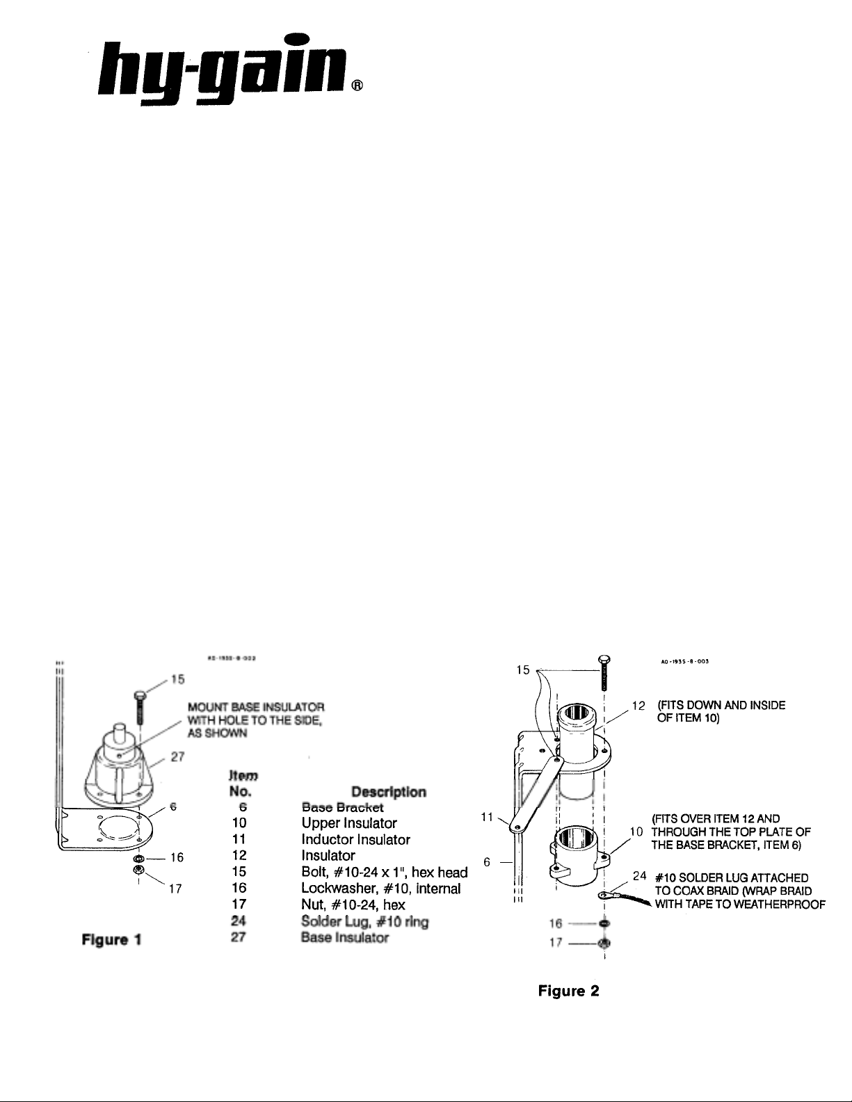
Select the base bracket and the lower base insulator and install as shown in
Fi
ure 1.
Select the two upper base insulators and the base inductor insulator strap and
install as shown in Fi
ure 2.
Figure 3
Page 3
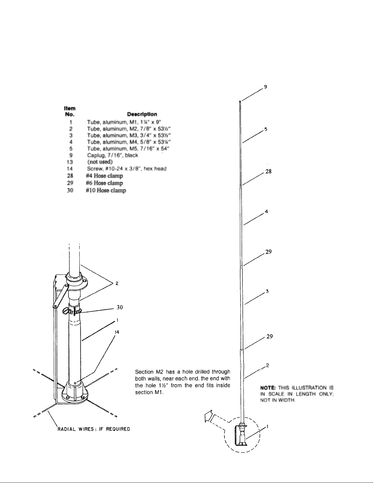
Select the M1 section of tubing (1 1/4") and place It over the top of the lower
base insulator. Align the hole in the base of the M1 section of tubing with the
hole in the lower base insulator as shown in Figure 3. Place a #10 (Item 14)
screw in the hole and tighten securely.
(%s"
Select the M2 section
upper insulators (see Figure 2) into the M1 section.
x 531/2") and slip the small hole end through the two
Fasten with #10 hose
clamp (Item 30) as shown in Figure 3.
Figure 3
Page 4
Select the M3 section (3/4" x 531/ 2") and s lip t he en d wi th th e sm alles t hole
g
)
into the
M2 section and fasten with #6 hose clamp (item29).
Operation
Select the M4 section
Select the M5 section ('/,s"
(5/e"
x 53'/4") and slip the end with the smallest hole into
x 54") and slip the slotted end into M4 section.
Fasten with #4 hose clamp (item 28).
Place a 7/16" caplug on the end of the antenna.
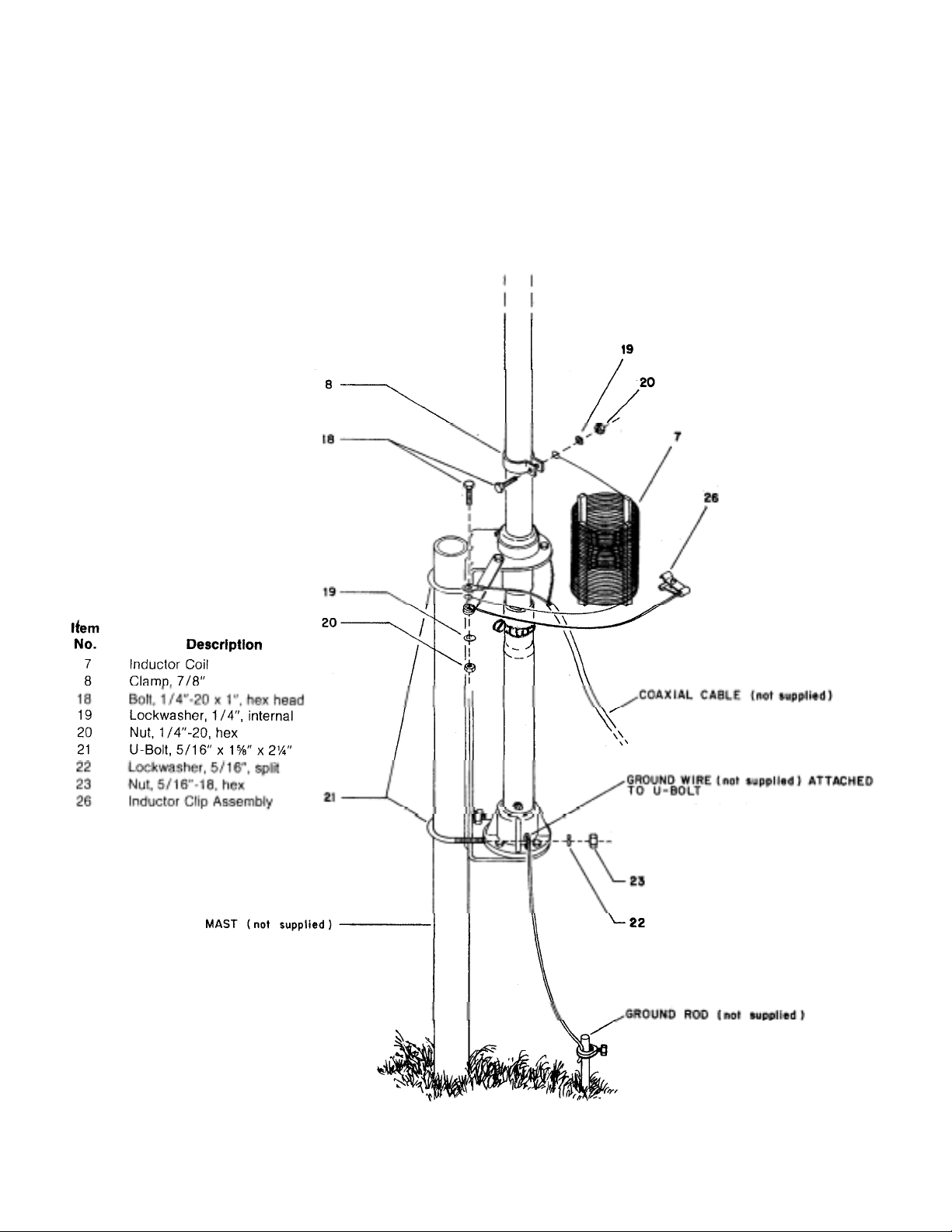
Now select the base inductor coil, the tuning clip and the short length of wire.
Install as shown in Fi
NOTE: Coax cent er co nduc tor m ust a lso be con nect ed as s hown in F igure 4.
Attach th e top lead of t he bas e i nductor c oil to the M2 sec tio n (j ust a bove the
M1 section
Attach the coax to your transmitter. Attach the tuning clip to the base inductor
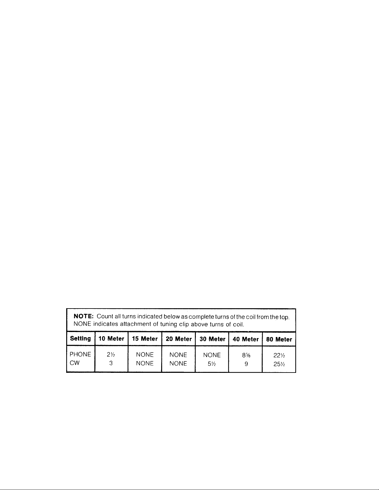
and tighten it securely. The chart shows an approximate setting. When
counting the turns, count from the top
clip are automatically shorted out to allow you to operate the antenna at full,
legal power o utput wit hout ov erheati ng the bas e induct or with RF energ y.
as shown in Figure 4.
ure 4.
-
of the coil. The unused turns below the
The chart on this page should be reasonably close, but due to different
mounting locations, different soil conductivity, and other variations in your
individual installation, the exact match is best determined by using an SWR
bridge with your transmitter and tapping for lowest SWR. The figures shown in
the chart are for ground mounting only. Due to the variations in the length of
the ground wire, it is impossible to provide a chart for elevated mounting.
NOTE: Connect tuning clip right at clamp connection on the M2 section when
Page 5
Ground Mounting Drive a 3 foot piece of pipe (such as 1
1/4"
plumbers pipe) into the ground and
attach the antenna as shown in Figure 4. Drive an 8 foot copper-clad steel
ground rod into the ground. Attach the ground rod to the base using #10 wire.
Remember, a vertical antenna is only as good as the ground system it is
working over. The better the ground system, the better your antenna will
work. If difficulty is experienced, try adding 2 or 3 more ground rods about the
antenna base and attach each with a separate wire. Radials may be attached
to the ground rods for increased efficiency.
Elevated Mounting The Model 18V-S can be mounted alongside the house on a short mast or
on top of the roof us ing a shor t mast se ction.
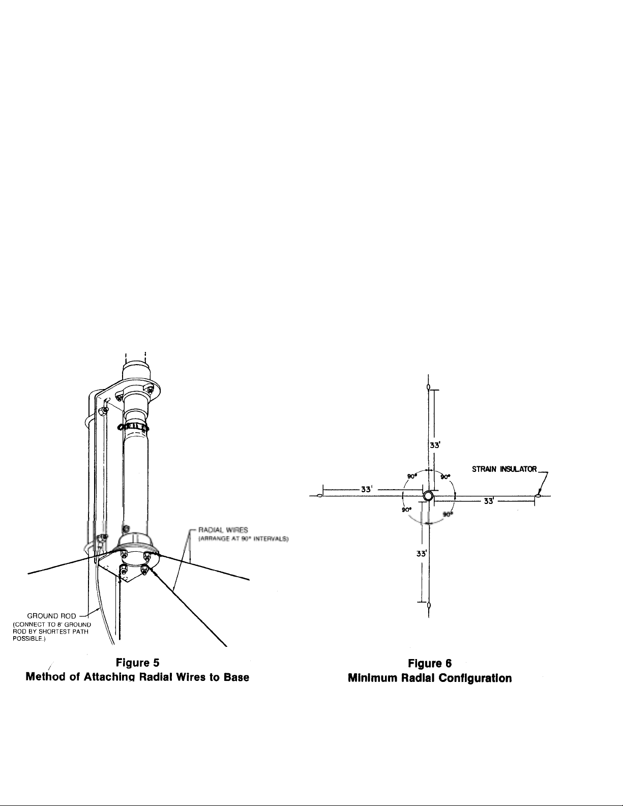
above the ground, you must use a radial system similar to that shown in Figure
When mounting more than 24"
5. This radial system should then be grounded to an earth ground by the
shortest path possible.
Mount it only as shown in this manual.
CAUTION
Make certain none of the radial wires touch the inductor coil or damage to
your transmitter or antenna could occur.
Do not change the mounting point of the base inductor.
Page 6

Item
,
,
p
The radials can be constructed of either copper or aluminum wire. The
recommended method of installing the radia ls is to attach them to the screws at the
bottom of the base assembly. The 33 foot dimension is measured from the base
assembly to the strain insulator, and is optimum for 40 meter operation only. You
may wish to add shorter or longer radials f or other bands that you plan to oper ate on.
WARNING
The antenna and radials are "hot with RF" proportional
to the operating power. Be sure to keep out of the reach
of small children and pets.
1 177963 Tube
2 173276 Tube, aluminum, M2, %" x 53'/2" . . . . . . . . . . . ... . . . . . . .. .. . . . . . . . .1
3 173274 Tube, aluminum, M3,
4 173273 Tube, aluminum, M4,
aluminum, M1 1'/4" x 9.................................... 1
3
/4"
x 53'/2" ............... ....... . . ... . ..1
5/8"
x 53'/4" .... ... ....... . . . . . ... . . .. .. . ...1
5 173272 Tube, aluminum, M5, '/,s" x 54................................... 1
6 160043 Bracket, base ................................................. 1
7 723267 Coil, inductor ................................................. 1
872000 Parts Pack 18V-S, Stainless Steel ............................... 1
8 169339 Clamp, %.................................................... 1
9 455644 Caplug, '/,s" (black) ......................................... 1
1 463056 Insulator, upper ............................................. 1
1
(Not Used)
1 478002 Insulator ................................................... 1
1
1 526472 Screw
1
1
1 554071 Nut, #10-24, hex .......................................... 9
1
1
2
2
2
2
2
2
2 872817 Inductor cli
515852 Screw, #8 x '/2", pan head, Type A, slotted ..................... 2
#10-24 x
3
/8",
hex head, slotted ......................... 1
504069 Boll, #10-24 x 1", hex head ..................................7
565697 Lockwasher,#10,internal ..................................... 7
502958 Bolt, '/4
562961 Lockwasher,'/4
554099 Nut, '/4"-20, hex ............................................. 2
543792 U-bolt,
564792 Lockwasher,
555747 Nut,
"
-20 x 1 ", hex head ................................... 2
5
"
,internal ..................................... 2
5
5
/8"
/,s"
x 1
x 2'/4........................................ 2
5
/,8",split ....................................... 4
/,8"-18, hex ............................................ 4
678922 Solder lug, #10 ring .........................................1
(Not Used)
assembly....................................... 1
2 877961 Insulator,base..............................................1
2
2
3
745-3104S #4 Hose c la m p (358759) ...............................................................1
745-3106S #6 Hose c la m p (358756) ...............................................................2
745-3110S #10 Hose clamp (358757) .............................................................1
Page 7
ADDENDUM
ENGINEERING REPORT
PHASED MULTI-BAND
VERTICALS for ADDITIONAL GAIN and
LOW ANGLE RADIATION
AMATEUR
PHASING
INTRODUCTION
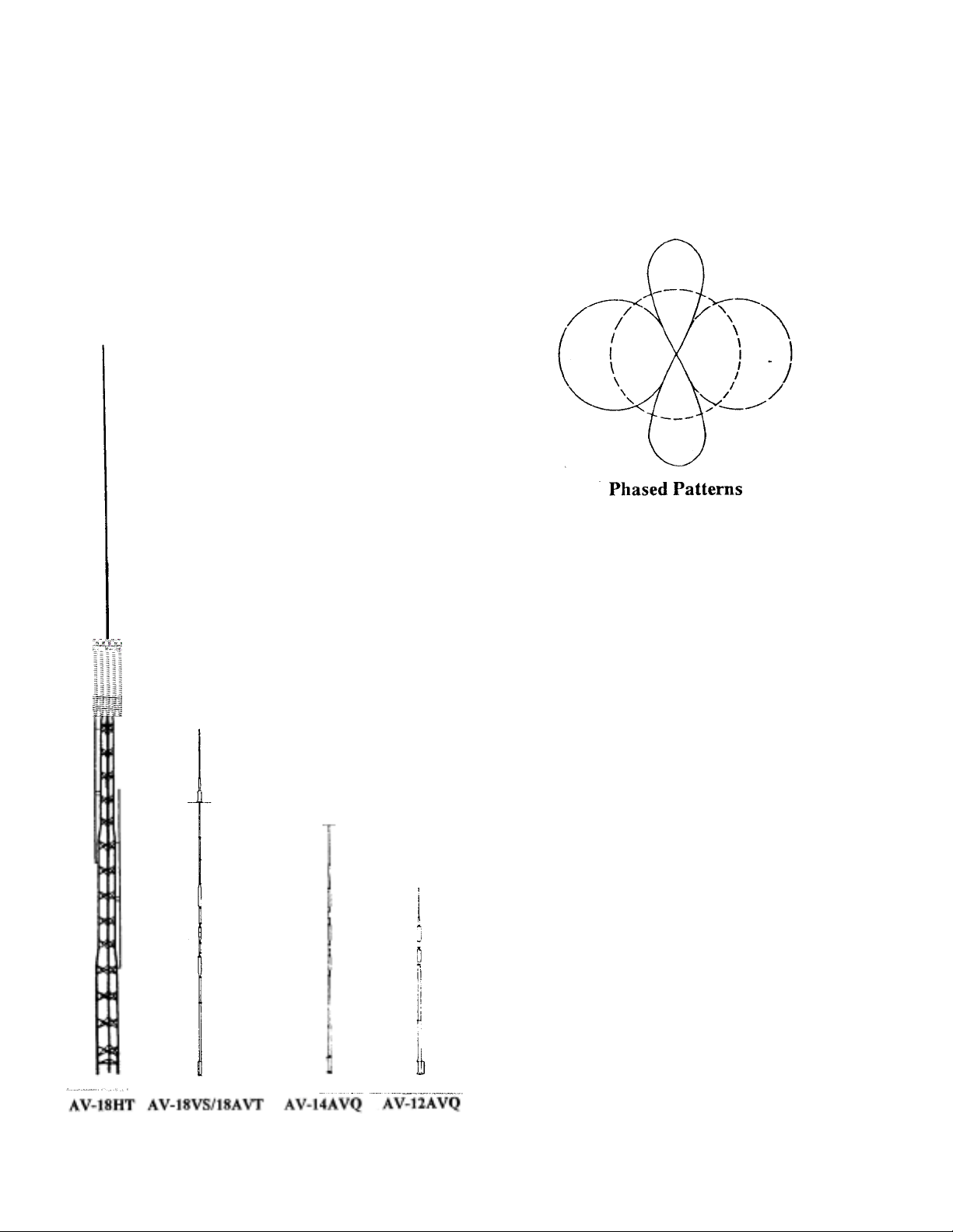
The following Hy-Gain verti cals ar e well
adapted for the phasing arrangements
MODEL 18HT-S HY-TOWER
The 18HT-S is a multi-band vertical antenna
with automatic band selection of 10-80 meters
by means of a unique stub decoupling system.
The Hy-Tower with a base loading coil
operates efficiently on 160 meters. The system
is foolproof, fed directly with a single 50 ohm
coax. No guys are required for the 24 feet high,
self-supporting tower. The top mast extends
the height to 50 feet. Two units make an ideal
phased array.
MODEL 18AVT/WB-S
The 18AVT/WB-S is a multi-band trap vertical
for 10 through 80 meters. It is completely factory pre-tuned and exhibits an extremely low
angle DX radiation pattern. It is easy to assemble, li ght we ight wh ich o ne m an c an i nst all.
A single 50 ohm co axia l feedli ne is requi red.
Two or thre e 18AVT/W B-S 's make an
excellent ph ase d a rra y.
Page 8

MODEL 14AVQ/WB-S
Q
p
(Four Quadrants)
The 14AVQ/WB-S is a self supporting multiband trap vertical for 10 through 40 meters
and is completely factory pre-tuned. It is the
world's most popular ham antenna with an
overall height of 19 feet. The antenna is
thoroughly weatherproofed and has a low
angle DX radiation pattern. It may be ground
mounted or installed on "Roof Top" with a
radial system.
MODEL 12AV
The 12AVQ is a self supporting 13 1/2 foot
multi-band trap vertical for 10, 15 and 20
meters. Completely factory pre-tuned with
SWR of 2:1 or less with a low angle DX radiation pattern. The antenna has a new fiberglass
impregnated styron base insulator. It may be
ground mounted with earth acting as the
"image antenna" or installed on the roof using
a radial system.
Increased activity on 80 and 40 meters has
created a need for an antenna with power gain
and directivity. Doublet and long wire
antennas are no longer effective due to
increased QRM. At these low frequencies, the
radiation system must be lengthy and height
above ground is extremely important to obtain
the "low" angle of radiation needed for DX.
Beams are excellent, but require a large supporting tower and "hefty" rotating system.
Inverted V dipoles and slopers require a large
tower and
The vertical "phased array", the answer for
"DX" on these frequencies combine gain,
directivity and low angle radiation, the three
most important DX factors in a communication
installation. The vertical is well known for its
low angle characteristics. When you combine
two identical verticals, properly spaced and
phased, the resultant is a concentrated low angle
of energy and a power gain. These antennas can
be so arranged to give a definite effect on either
one or two favorite bands or all band coverage
with some pattern compromise and slight loss
of gain.
The following data was experimentally derived
on the Telex/Hy-Gain test range. Due to the
many factors that vary and influence the
performance of an antenna, such as grounding
and close proximity of surrounding objects,
etc., Telex/Hy-Gain cannot guarantee an
installation to perform or exhibit the same
characteristics as outlined in this report.
However, many Amateurs are now successfully
using these arrangements. Commercial
broadcast stations have been using a similar
phasing arrangement for years.
lenty of property.
Part 1 - SINGLE BAND
BI-DIRECTIONAL ARRAY
THEORY' OF OPERATION
Two identical vertical antennas can be
installed as a phased array. When excited by
RF energy, gain is achieved by control of the
directional pattern. This direction pattern
control results in added gain by sharpening
lobe patterns and concentrating the radiated
energy at very low angles. Signal flutter is
reduced and reception is vastly improved.
Phased arrays will reduce installation height requirements and still maintain low angle
radiation.
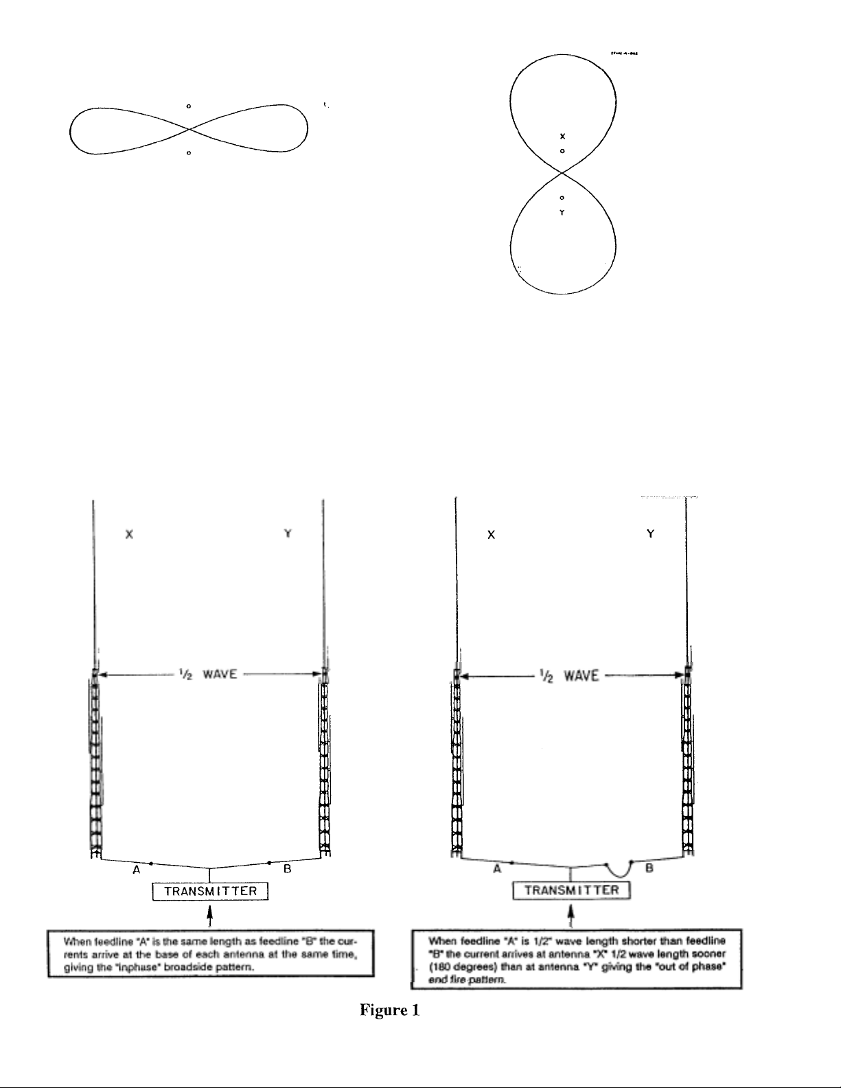
Most effective spacing for a bi-directional
array is 1/2 wave length. When two verticals
are excited in phase the radiation is broadside
to the plane of the verticals, offering
substantial gain and bi-directional
characteristics. Side nulls offer excellent signal
cancellation to the undesired direction.
Page 9
Y
When excited "o ut of phase" these sam e verticals can be made to give an "end fire" or bidirectional pattern in the opposite direction
through the plane of the verticals. This then
nulls out signals in the opposite directions.
More gain is exhibited by the broadside
pattern over the "end fire" arrangement, but
the "end fire" arrangement offers a wider
frontal pattern .
Both arrangements offer an excellent advantage over a single vertical since either
phasing combination exhibits noticeable
signal gain with side attenuation of undesired
signals. This added gain and low angle
vertical directivity is the advantage of the
phased array.
"ENDFIRE" GAIN 23 dB
Phased verticals may be spaced either one
quarter wave or one half wave depending
upon gain and directional characteristics. The
nulls of the phased array are extremely sharp
and very pronounced. Typical arrangements of
phased arrays and their electrical
specifications are illustrated below.
Page 10
SPECFICATIONS
Broadside End Fire
Pattern width, half power points 60 degrees 80 degrees
Gain over single vertical 3.86 dB 2.3 dB
Side attenuation 30 dB 20 dB
Impedance 50 Ohms 50 Ohms
Directional characteristics Bi-Directional Bi-Directional
Figure 2
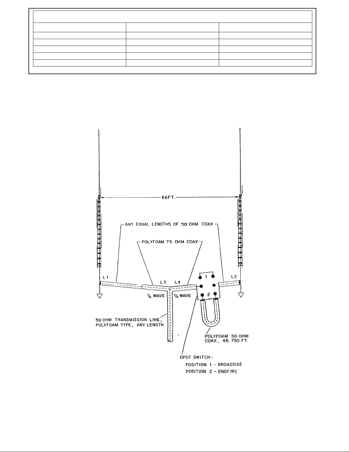
Typical Installation Phased (2) 18 HT 40 Meters
7200 KHz Design Frequency
Page 11
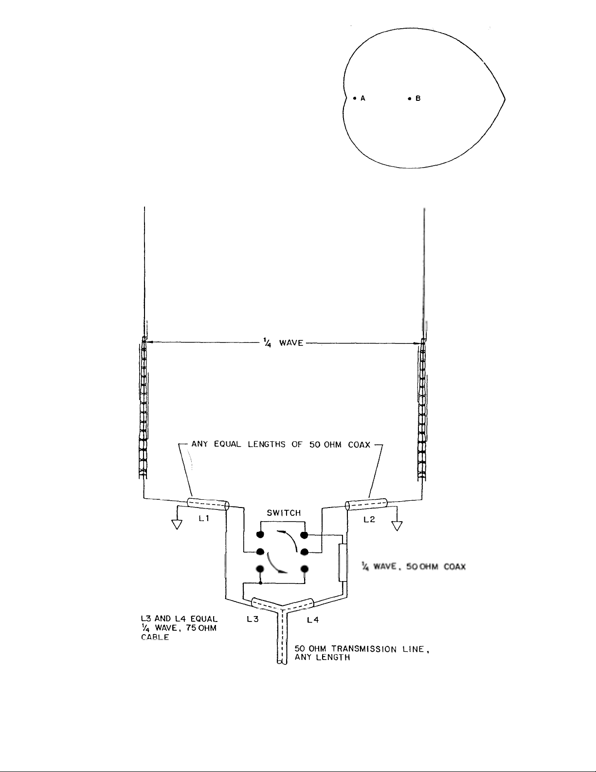
CARDIOID ARRAY
(
)
Uni-directional
When two or three identical verticals are excited directly and fed 90 degrees out of phase
with a spacing of 1/4 wave length, a cardioid
pattern results. This pattern may be switched in
either direction. B y inserting a 1/4 wave l ength
delay line the antenna will "fire" or be directive
to that particular element. .:
TWO VERTICALS
Cardioid-Unidirectional With Two Selectable Directions
Page 12
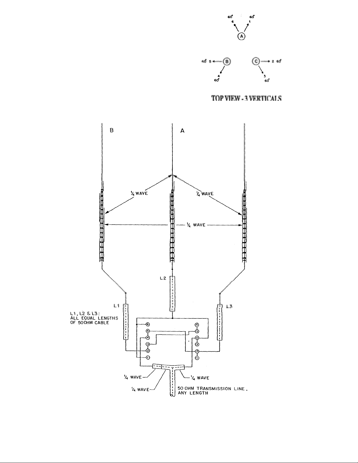
The beam pattern for two 1./4 wave length
verticals will be approximately 120 degrees.
An arrangement of three switchable verticals
gives a 60 degree pattern in six selectable
directions.
Figure 4
360 Cardioid Arrangement
Page 13

)
t.
ELECTRICAL SPECIFICATIONS:
Two Phased Verticals Three Phased Verticals
Pattern Width, half power points 120 degrees 60 degrees
Gain over single vertical 4.5 dB 4.5 dB
Side attenuation 20 dB 20 dB
Rear attenuation 30 dB 30 dB
Impedance 50 Ohms 50 Ohms
Directional Characteristics Uni-directional Uni-directional
VSWR: Exceptionally low SWR is present with a phased array. If phasing lines are
correctly measured and the terminal impedance of each antenna is very close to 50 Ohms:
Typical SWR: Broadside 1.2:1, Endfire 1.4:1, Cardioid 1.2:1.
PHASING LINES:
The 1/4 and 1/ 2 wave tr ans formers, identified as L3, L4 and L5 are calculated from the
lowing formula:
1/4 wave
246000 x vel.
vel. factor - reg. coax.
frequency (in KHz
EXAMPLE:
34.16
1/4 wave at 7200 KHz = 246000 / 7200 = 34.16
x.75
25.62
1/4 wave = 25.62
f
PART 2 - MULTI-BAND OPERATION
MULTI-BANDING
Multi-banding is easily accomplished by
choice spacing two identical verticals. (refer
to charts A,B, and C and associ ated Figures 1
through 5) Switchable 1/4 wave length and 1/2
wave length phasing cables must be employed
for each band. These cables can be placed in
the station in any suitable fashion along with a
manual switching arrangement or relay
system.
Considerat ion must be given to the f act th at 1/2
wave spacing (optional) is ideal for phasing.
When multi -banding with clos e and wide sp acing, compromise radiation patterns must be
expected. In most cases a choice spacing serves
3 bands most eff ectively with good direct ional
characteristics, added gain and low angle performance.
Page 14

OPTIONAL SPACIN G
in use to obtain an omnl-directional pattern.
y
SWITCHES & CONNECTORS
Various antenna spacings may be selected
from charts A, B, and C, for single band, duo
band or multi-band arrangements. Associated
radiations patterns for a specific spacing is
shown in Figures 1 through 5 for each band.
If the 3/4 wave length patterns are not
desirable, a single vertical only can be switched
INSTALLATION
The vertical antenna requires a minimum
amount of space. Ground mounted or elevated
arra
s are easily installed.
Antenna placement and orientation is a most
important factor when planning maximum effectiveness is desired directions. Each vertical
should be installed in the clear relatively free of
surrounding objects in order to maintain its
design 50 Ohm terminal impedance.
Each antenna must be mounted at the same
height on or above ground and be so arranged
according to their radiation pattern to offer
desired directivity.
The phased array is primarily designed for long
range and DX communications. In cases where
close and medium distance contacts are
hampered by the array's low angle characteristics and a higher angle is required, switching
arrangements can select one vertical for this
coverage.
Low loss constant impedance type coaxial
switches and connectors should be used when
splicing phasing lines. B&W multi-position,
single or multi-gang coaxial switches with Amphenol coaxial cable and "T' connectors are
recommended.
FIELD TESTS
Actual field tests comparing one vertical to the
phased array results in doubling the receivers
sensitivity and offering up to 12 dB of signal
increase. An attenuation of up to 30 dB is
noticeable on the phased verticals with half
wave spacing. With quarter wave spacing, up
to 20 dB cardioid, and 30 dB front-to-back attenuation can be obtained.
"End Fire" directivity offers a larger area of
radiation at slightly reduced gain as compared
to the broadside arrangement. The "broadside" arrangement is recommended for
communications at greater distances whereas
the "endfire" arrangement would be so arranged to cover a larger area of
communications. Special attention to the coax
phasing line lengths and their proper
placement is of utmost importance.
Page 15
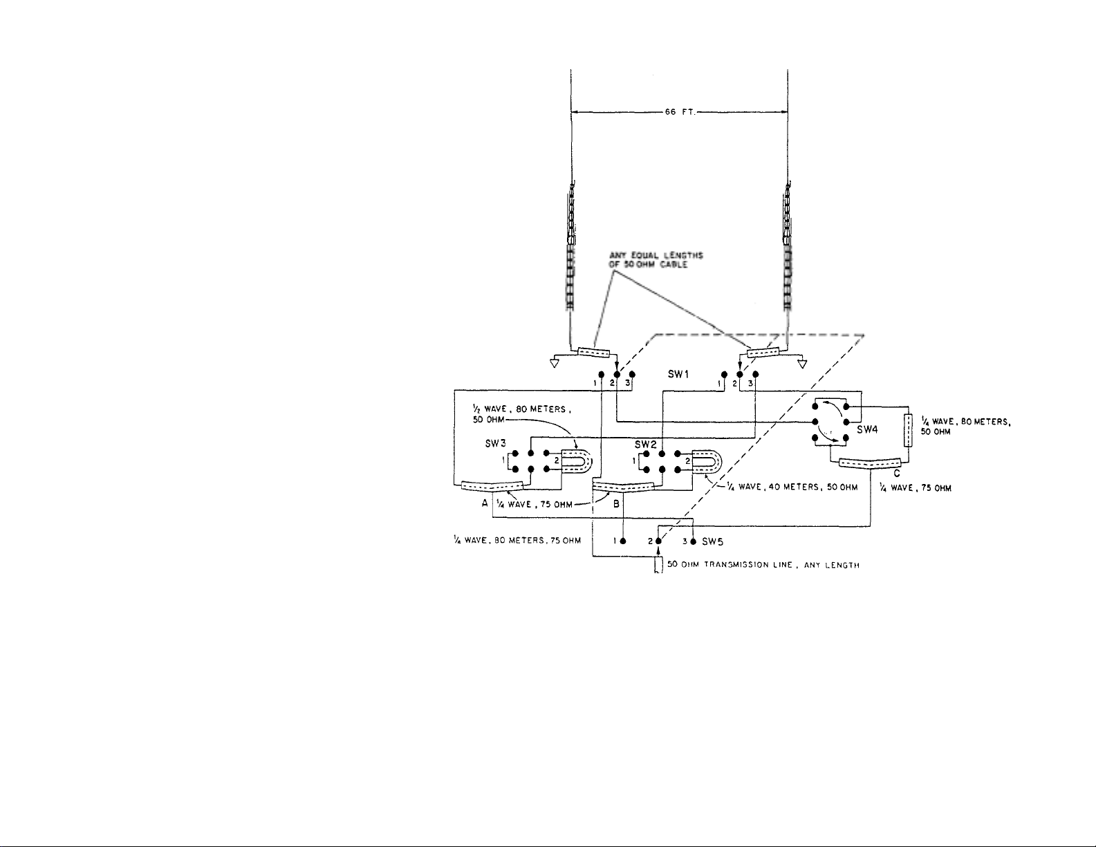
A. 80 meter bi-directional pattern (all SW positions 3) refer
to Figure 1, Part 2 "Radiation Patterns"
NOTE: Due to clos e electrical spacing (1/4 wave) on
80 meters for Broadside (position 1) and Endure
(position 2) the SVWR may be somewhat higher than
1/2 wave spacing. SW3 selects direction
B. 40 meters all switches in position 1 selects Bi-
Directional patterns. Use SW2 for broadside (position
1) Endfire (positio n 2).
C. All switches in position 2 selects cardioid pattern. SW4
selects direction of cardioid pattern.
NOTE: All connecting lines are exaggerated in length. These
lines must be direct and short as with any coax hook-up practice.
Figure 5
Typical installatio n (2) 18 HT-S Pha sed fo r 80 and 40
Meters Selectab le Broad side a nd Endfi re Patter s on 40
Meters Select abl e Broad sid e and E ndfi re Patt erns o n 80
Meters Select able 2 Di recti ons Cardi oid on 80 Meters
Page 16
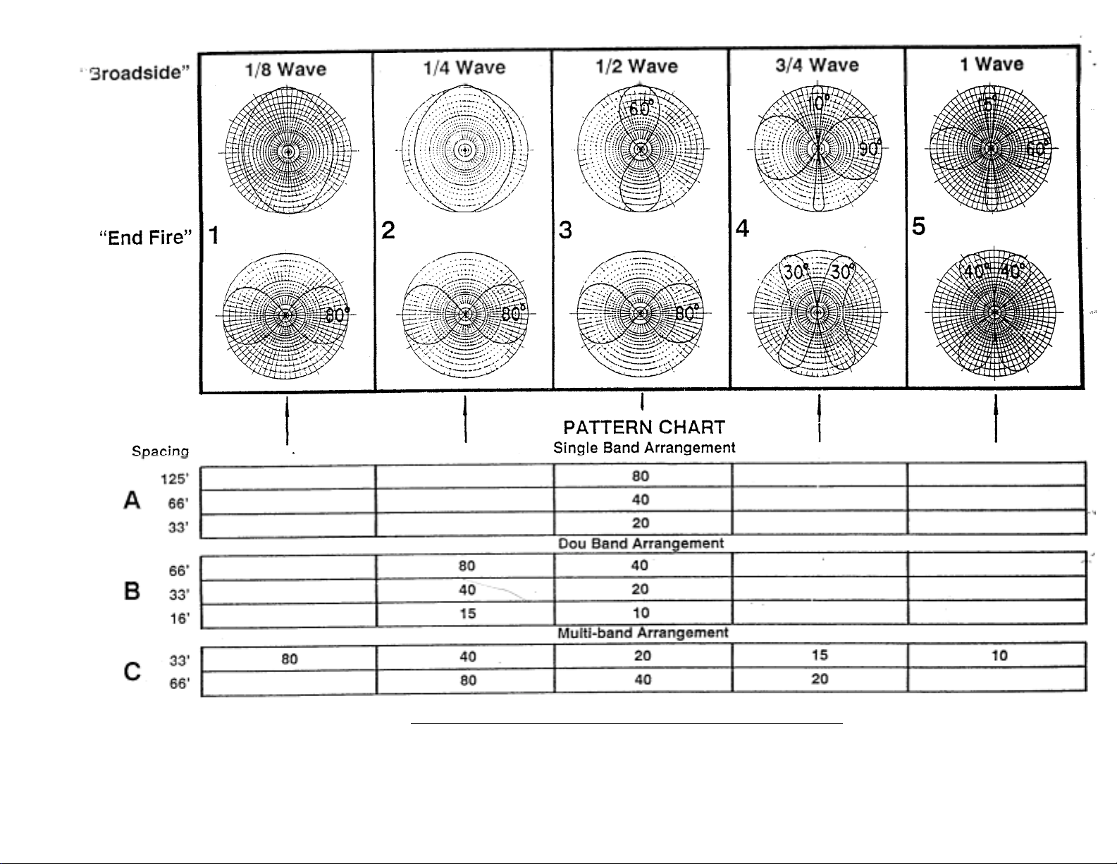
Note: Corralate Patterns to spacing used in installation
Figure 6
Radiation Patterns - Typical Spacing For Broadside And Endfire Arrangements
 Loading...