

HYDIS HX121WX1-121 Specification
PROPRIETARY NOTE
THIS SPECIFICATION IS THE PROPERTY OF HYDIS AND SHALL NOT
BE REPRODUCED OR COPIED WITHOUT THE WRITTEN PERMISSION OF
HYDIS AND MUST BE RETURNED TO HYDIS UPON ITS REQUEST
TITLE : HX121WX1-121
Product Specification
SPEC. NUMBER
S864-1429
B2005-C001-D (1/3)
HYDIS Technologies
PRODUCT GROUP
REV.
ISSUE DATE
2010.12.150TFT LCD
PAGE
PAGE
1
OF 33
A4(210 X 297)
A4(210 X 297)
PRODUCT GROUP REV ISSUE DATE
TFT LCD PRODUCT 0 2010. 12.15
REVISION HISTORY
REV. ECN NO. DESCRIPTION OF CHANGES DATE PREPARED
0 Initial Release ‘10.12.15 J. T. LEE
SPEC. NUMBER
S864-1429
B2005-C001-D (2/3) A4(210 X 297)
SPEC TITLE
HX121WX1-121 Product Specification
2
PAGE
OF 33
PRODUCT GROUP REV ISSUE DATE
TFT LCD PRODUCT 0 2010. 12.15
Contents
No Item Page
1.0 General Description 4
2.0 Absolute Maximum Ratings 6
3.0 Electrical Specifications 7
4.0 Optical Specifications 9
5.0 Interface Connections 14
6.0 Signal Timing Specifications 16
7.0 Signal Timing Waveforms 16
8.0 Input Signals, Basic Display Colors & Gray Scale of Colors 18
9.0 Power Sequence 19
10.0 Mechanical Characteristics 20
11.0 Mechanical Drawing 21
12.0 Reliability Test 24
13.0 Handling & Cautions 24
14.0 Labels 26
15.0 Packing Information 28
16.0 EDID 30
SPEC. NUMBER
S864-1429
B2005-C001-D (3/3) A4(210 X 297)
SPEC TITLE
HX121WX1-121 Product Specification
3
PAGE
OF 33
PRODUCT GROUP REV ISSUE DATE
TFT LCD PRODUCT 0 2010. 12.15
1.0 GENERAL DESCRIPTION
1.1 Introduction
HX121WX1-121 is a color active matrix TFT LCD module using amorphous silicon TFT's
(Thin Film Transistors) as an active switching devices. This module has a 12.1 inch
diagonally measured active area with WXGA resolutions (1280 horizontal by 800 vertical
pixel array). Each pixel is divided into RED, GREEN, BLUE dots which are arranged in
vertical Stripe and this module can display 262,144 colors. The TFT-LCD panel used for this
module is a low reflection and higher color type.
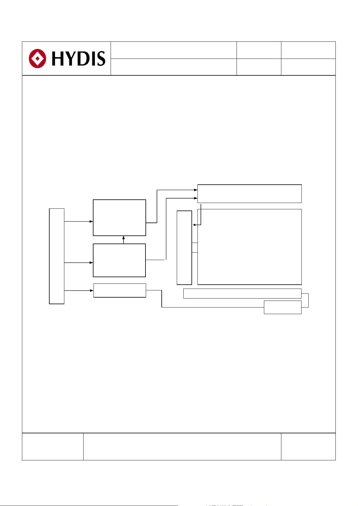
eDP
Input
Signal
Connector (CN
eDP Rx
+
T/CON
Gate Driver
TFT LCD Panel
1
VDD
1
)
DC/DC
Gamma
Vcom
HVDD
VDIM
LED Driver
1.2 Features
z Thin and Light Weight
z 3.3 V Logic Power Supply
z 12V Back-light Power Supply
z 1 lane eDP Interface
z SMD LED (48EA) Array (Bottom Side/Horizontal Direction)
z 262,144 Colors
z Data Enable Signal Mode
z Side Mounting Frame
z Green Product (RoHS)
BACK LIGHT (Fluorescent Lamp)
Back Light (SMD LED Array)
Source Driver
1280 ×800
CN2
SPEC. NUMBER
S864-1429
SPEC TITLE
HX121WX1-121 Product Specification
4
PAGE
OF 33
B2005-C001-D (3/3) A4(210 X 297)
PRODUCT GROUP REV ISSUE DATE
TFT LCD PRODUCT 0 2010. 12.15
1.3 Application
z Tablet PC (Wide type)
1.4 General Specifications
Parameter Specification Unit Remarks
Active area 261.12(H) ×163.20(V) mm
Number of pixels 1280(H) ×800(V) pixels
Pixel pitch 0.204(H) ×0.204(V) mm
Pixel arrangement RGB Vertical Stripe
Display colors 262,144 colors
Display mode Normally Black
Outline dimension
276.8±0.3(H) ×180.0±0.3(V) ×6.8(D:Max.)
mm Note 1
Weight 265(Typ.) / 275(Max.) g Note 2
Back-light SMD LED (48EA) Array
Surface treatment AGLR, 3H
Note 1 : At PCB side (LED Side: 4.6mm Max.)
Note 2 : Without digitizer
SPEC. NUMBER
S864-1429
SPEC TITLE
HX121WX1-121 Product Specification
5
PAGE
OF 33
B2005-C001-D (3/3) A4(210 X 297)
PRODUCT GROUP REV ISSUE DATE
(
)
(40,
)
(
)
(
)
TFT LCD PRODUCT 0 2010. 12.15
2.0 ABSOLUTE MAXIMUM RATINGS
The followings are maximum values which, if exceed, may cause faulty operation or
damage to the unit.
Parameter Symbol Min. Max. Unit Remarks
Ta=25+/-2°C
Logic Power Supply Voltage V
Logic Power Supply Voltage V
Back-light Power Supply Voltage HV
Back-light LED Current I
LED
Back-light LED Reverse Voltage V
Operating Temperature T
Storage Temperature T
DD
IN
DD
R
OP
SP
-0.3 4.0 V
-0.3 VDD+0.3 V
-0.3 40 V
-30mANote 1
-5V
0+50
℃
Note 1, Note 2
-20 +60
℃
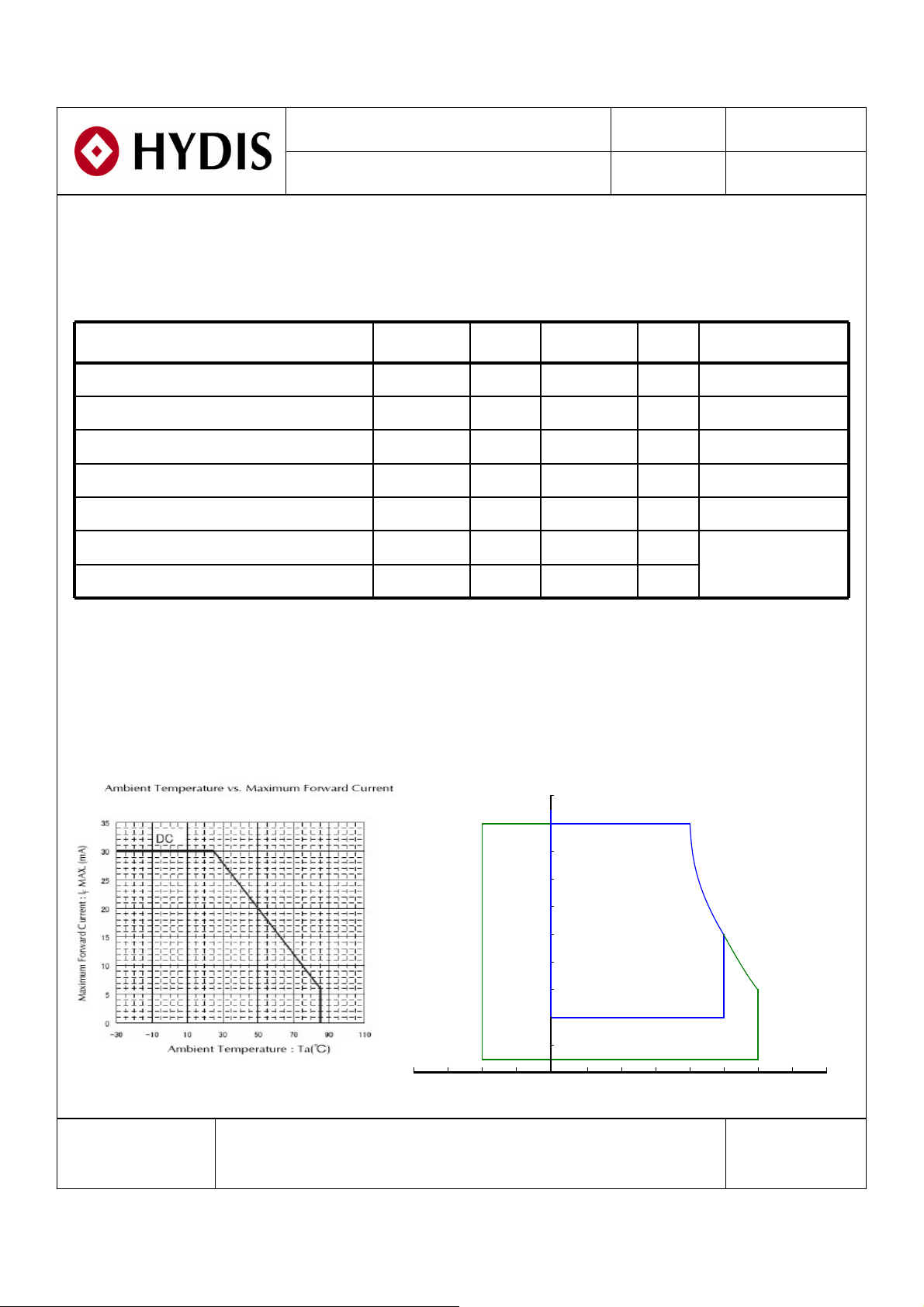
Note 1. Ambient temperature vs allowable forward current are shown in the figure below.
Note 2. Temperature and relative humidity range are shown in the figure below.
90% RH Max. ( 40℃≥Ta)
Maximum wet - bulb temperature at 39℃ or less. ( > 40℃) No condensation.
100
90
90
80
60
Operating Range
40
20
50, 50
60, 27
Storage Range
5
-40 -20 0 20 40 60 80
SPEC. NUMBER
S864-1429
SPEC TITLE
HX121WX1-121 Product Specification
Temperature
PAGE
OF 33
6
B2005-C001-D (3/3) A4(210 X 297)
℃
PRODUCT GROUP REV ISSUE DATE
TFT LCD PRODUCT 0 2010. 12.15
3.0 ELECTRICAL SPECIFICATIONS
3.1 Electrical Specifications
< Table 3. Electrical Specifications >
Parameter Min. Typ. Max. Unit Remarks
Logic Power Supply Voltage V
Logic Power Supply Current I
Back-light Power Supply Voltage HV
Back-light Power Supply Current I
HVDD
Back-light Power Consumption P
DD
DD
DD
BL
3.0 3.3 3.6 V Note 1
- 346 470 mA Note 1
7.0 12.0 20 V Note 2
- 255 305 mA Note 2, 3
- 3.06 3.66 W Note 2, 3
LED Driver’s Efficiency η - 82 - % Note 2, 3
Back-light PWM Frequency F
High Level PWM Signal Voltage V
Low Level PWM Signal Voltage V
High Level Differential Input Signal
Voltage
Low Level Differential Input Signal
Voltage
Back-light LED Voltage /
Back-light LED Total Voltage
PWM
PWMH
PWML
V
IH
V
IL
V
LED
/V
BL
200 280 350
㎐
2.1 3.3 5.0 V
-00.6V
- - +100 mV VCM= 1.2V
-100 - - mV
-
3.1
/ 37.2
3.5
/ 42.0
V Note 4
Back-light LED Current /
Back-light LED Total Current
Life Time
Power Consumption
SPEC. NUMBER
SPEC TITLE
S864-1429
16.9
/ 67.6
P
P
I
/I
P
LED
BL
LED
total
-
12,000
D
- 1.14 1.55 W Note 1
- 2.51 2.99 W Note 4
- 3.65 4.54 W Note 1, 4
HX121WX1-121 Product Specification
- - Hrs Note 6
17.8
/ 71.2
mA Note 4
7
PAGE
OF 33
B2005-C001-D (3/3) A4(210 X 297)
PRODUCT GROUP REV ISSUE DATE
TFT LCD PRODUCT 0 2010. 12.15
Notes : 1. The supply voltage is measured and specified at the interface connector of LCM.
The current draw and power consumption specified is for 3.3V at 25℃.
a) Typ : Window XP pattern, b) Max : Vertical Sub line pattern
c) EBL : Mosaic pattern ( 32 X 32 )
2. The power supply voltage and current is measured and specified at the interface
connector of LCM including LED Driver.
3. Reference value, which is measured with LED Driver for 12V.
4. Reference value, which is measured without LED Driver.
5. Calculated value for reference (V
LED
× I
× # of LEDs (48EA) ).
LED
6. End of Life shall be determined by the time when any of the following is satisfied
under continuous lighting at 25℃ and ILED = 16.9mA.
-. Intensity drops to 50% of the Initial Value (Luminance Spec.)
-. Based on LED
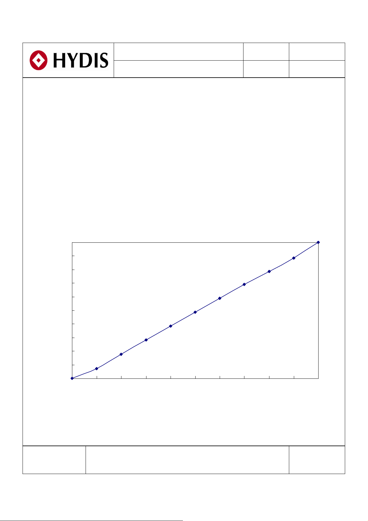
3.2 PWM Duty Ratio vs Brightness
Relative Brightness (% )
100
90
80
70
60
50
40
30
20
10
0
0 102030405060708090100
Duty Ratio (%)
SPEC. NUMBER
S864-1429
SPEC TITLE
HX121WX1-121 Product Specification
8
PAGE
OF 33
B2005-C001-D (3/3) A4(210 X 297)

PRODUCT GROUP REV ISSUE DATE
TFT LCD PRODUCT 0 2010. 12.15
4.0 OPTICAL SPECIFICATIONS
4.1 Overview
The test of optical specifications shall be measured in a dark room (ambient luminance ≤ 1
lux and temperature = 25±2℃) with the equipment of Luminance meter system (Goniometer
system and TOPCON BM-5A) and test unit shall be located at an approximate distance
50cm from the LCD surface at a viewing angle of θ and Φ equal to 0°. We refer to θ
(=θ3 ) as the 3 o’clock direction (the “right”), θ
(“upward”), θ
(= θ9 ) as the 9 o’clock direction (“left”) and θ
Ø=180
(= θ12 ) as the 12 o’clock direction
Ø=90
(= θ6 ) as the 6
Ø=270
o’clock direction (“bottom”). While scanning θ and/or Ø, the center of the measuring spot on
the Display surface shall stay fixed. The backlight should be operating for 30 minutes prior to
measurement. VDDshall be 3.3+/- 0.3V at 25°C. Optimum viewing angle direction is 6
o’clock.
4.2 Optical Specifications
<Table 4. Optical Specifications>
Parameter Symbol Condition Min. Typ. Max. Unit Remarks
Θ
Θ
Θ
Θ
3
9
12
6
CR > 10
Viewing Angle
Range
Horizontal
Vertical
Luminance Contrast Ratio CR
Luminance of
White
White
Luminance
Uniformity
Color
Chromaticity
5 Points Y
w
5 Points ΔY5 80 - -
13 Points ΔY13 60 - -
W
White
Red
Green
Blue
W
R
R
G
G
B
B
x
y
x
y
x
y
x
y
Θ = 0°
Color Reproduction 42 %
Outdoor
Spec.
Response
Time
Cross Talk CT
Brightness Center
Reflectance Ri 2.5 3.5 - % Note 8
Total
(T
r+Td
)
Ta= 25° C
Θ = 0°
Θ = 0°
Θ = 0°
-85-Deg.
-85-Deg.
-85-Deg.
-85-Deg.
500 700 - Note 2
250 300 - cd/m
% Note 3
0.273 0.313 0.353
0.289 0.329 0.369
0.528 0.568 0.608
0.333 0.373 0.413
0.313 0.353 0.393
0.549 0.589 0.629
0.112 0.152 0.192
0.005 0.135 0.175
- 30 - ms Note 5
- - 2.0 % Note 6
400 500 - cd/m
2
2
Ø=0
Note 1
Note 4
Note 7
SPEC. NUMBER
S864-1429
SPEC TITLE
HX121WX1-121 Product Specification
9
PAGE
OF 33
B2005-C001-D (3/3) A4(210 X 297)
PRODUCT GROUP REV ISSUE DATE
TFT LCD PRODUCT 0 2010. 12.15
Note : 1. Viewing angle is the angle at which the contrast ratio is greater than 10. The viewing are determined
for the horizontal or 3, 9 o’clock direction and the vertical or 6, 12 o’clock direction with respect to
the optical axis which is normal to the LCD surface (see FIGURE 1 shown in page 11).
2. Contrast measurements shall be made at viewing angle of Θ= 0° and at the center of the LCD
surface. Luminance shall be measured with all pixels in the view field set first to white, then to the
dark (black) state. (See FIGURE 1 shown in page 11)
Luminance Contrast Ratio (CR) is defined mathematically.
CR =
3. The White luminance uniformity on LCD surface is then expressed.
(See FIGURE 2~3 shown in page 12)
Uniformity ΔY=
4. The color chromaticity coordinates specified in Table 4 shall be calculated from the spectral data
measured with all pixels first in red, green, blue and white. Measurements shall be made at the
center of the panel.
5. The electro-optical response time measurements shall be made as FIGURE 4 shown in page 13 by
switching the “data” input signal OFF and ON. The times needed for the luminance to change from
10% to 90% is Tr, and 90% to 10% is Td. (See FIGURE 4 shown in page 13)
6. Cross-Talk of one area of the LCD surface by another shall be measured by comparing the luminance
(YA) of a 25mm diameter area, with all display pixels set to a gray level, to the luminance (YB) of
that same area when any adjacent area is driven dark. (See FIGURE 5 shown in page 13)
7. Measure condition: Light source is 6,000nits, 15 degree position & BLU on at Full white.
(See FIGURE 1 shown in page 11)
Luminance when displaying a white raster
Luminance when displaying a black raster
Minimum Luminance of 5(or 13) points
X 100 (%)
Maximum Luminance of 5(or 13) points
8. Reference : Standard White Plate (BaSO4)
Light intensity of the reflected light on LCD Module
Reflectance = × 100%
Output intensity of the reflected light on Reference
Measure condition: Light source is 6,000nits, 15 degree position & BLU off at Full white.
(See FIGURE 1 shown in page 11)
SPEC. NUMBER
S864-1429
SPEC TITLE
HX121WX1-121 Product Specification
10
PAGE
OF 33
B2005-C001-D (3/3) A4(210 X 297)
 Loading...