

Page 1
Page 2

Page 3

GENERAL INFORMATION
This manual applies to the following Hustler equipment lines:
Mini FasTrak 36/42
FasTrak 48/54
To the new o w n e r
The purpose of this manual is to assist owners and operators in maintaining and operating the FasTrak tractor and deck. Please read it carefully;
information and instructions furnished can help you achieve years of de pen d able performance.
A separate Engine Owner’s Manual is included with your owner’s packet
which contains additional engine information that will not be repeated in this
manual. You are urged to read it before attempting any operation or repair of
the engine.
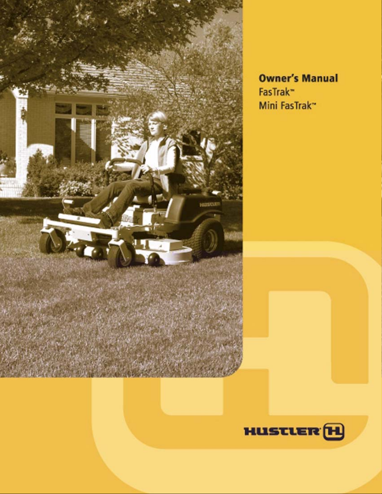
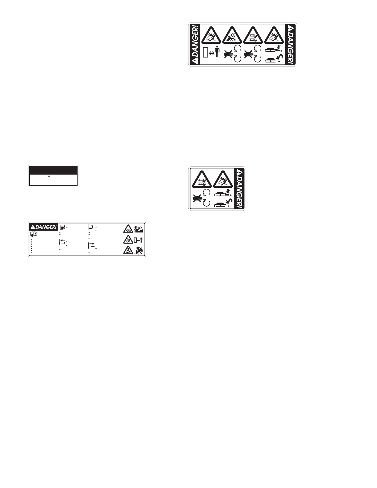
The Quick Reference Decals are designed to give the operator brief information needed in the daily operation and service of the machine. These
decals are not intended to be used in place of this manual but instead are to be
used as an extension of this manual. These decals should not be removed or
obliterated. Replace these decals if they become unreadable.
It is the oD077575Tw[(904 c( not r)-14.4(’)32.7(s r)15.7(e)not spoD077n)no2(sibili)-7.5(ty)]TJ/TT4 1 Tf9.5038 0 TD-0.0001 Tc0.1035 Tw[( to )-7.5(make )-7.5(certain that the )-7.5(operat)-8(or)-5.4( reads)]TJ-14.6992 -1.2481 TD0.0005 Tc0.0352 Tw[(and understands )7.5(this manual and all decal)]TJ16.8947 0 TD-0.0004 Tc0.0361 Tw[(s bef)-5.7(o)-077re operating this machine. It
Warranty registration
The Delivery and Warranty Registration form must be completed and
signed to validate your warranty protection. As the new equipment owner,
you are expected to see that the form is completed and forwarded to Husler
Turf Equipment at time of delivery.
Be sure to register the tractor plus each attachment that displays a model
and serial identification number plate with Hustler Turf Equipment.
IMPORTANT: Any unauthorized modification, alteration, or use of
non-approved attachments voids the warranty and releases Hustler Turf
Equipment from any liability arising from subsequent use of this equipment.
Model and serial number
Tractor model and serial numbers are found on the serial identification
plate, located on the frame directly below and to the right of the operators
patfo.
These numbers are required on the Warranty Registration form. They
will also assure you of the correct service parts when replacement becomes
necessary.
Parts and service
Use original Hustler replacement parts only. These parts are available
through your local Hustler dealer. To obtain prompt, efficient service, always
provide the following infoatiodering parts:
1. Correct part description
2. Correct model number.
3. Correct serial number.
All warranty repair and service must be handled through an authorized
Hustler dealer. Arrangem ents should be made th rough y our local service center.
WARNING:
The engine exhaust from this product
contains chemicals known to the State
of California to cause cancer, birth
defects or other reproductive harm.
IMPORTANT: This engine is n ot equipp ed with a sp ark arrester muf fler. It is a violation of California Public Resource Code Section 4442 to use or operate this
engine on any forest-covered, brush-covered, or grass-covered unimproved land. Other states or federal areas may have similar laws.
This spark ignition system complies with Canadian ICES-002.
The enclosed Engine Owner’s Manual is supplied for information regarding the U.S. Environmental Protection Agency (EPA) and the California Emission Control Regulation of emission systems, maintenance and warranty.
Keep this Engine Owner’s Manual with your unit. Should the Engine Owner’s Manual become damaged or illegible, replace immediately. Replacements may be ordered per the information found in the Product Information section of this manual.
601156_1106 1
Page 4

2 601156_1106
Page 5

MINI FASTRAK 36/42 TRACTORS & DECKS
HUSTLER TURF CONSUMER PRODUCT
THREE YEAR FULL WARRANTY FOR RESIDENTIAL USE
(90 DAYS LIMITED WARRANTY FOR COMMERCIAL USE)
WHAT IS COVERED BY THIS WARRANTY
Hustler Turf Equipment, makes the following warranty to the original purchaser only:
a. Residential use: Hustler Turf Consumer Products used for normal
residential purposes* are warranted for three (3) years from date of
delivery on all materials and workmanship.
If the Purchaser discovers within this warranty period (three years
from date of delivery) a defect in materials or workmanship:
● He must promptly notify Hustler Turf Equipment, or an authorized
dealer, in writing of the defect. In no event shall such notification
be received by Hustler Turf Equipment, or an authorized dealer later
than thirty-seven (37) months from date of delivery.
● Within a reasonable time after such notification, Hustler Turf
Equipment, will correct any defect in material or workmanship on
the Hustler Turf Equipment, by repairing or replacing part(s) with
either new or used replacement parts.
● Such repair, including parts and labor shall be at the expense of
Hustler Turf Equipment, and,
* Normal residential purpose means use of product on same lot as
your home. Use at more than one location is considered commerical
use, and then the commercial use warranty would apply.
b. Commerical use: Hustler Turf Consumer Products used for commer-
cial or institutional use are warranted for 90 days from date of deliv-
ery, on all materials and workmanship. (Rental use is warranted for
90 days)
NOTE: An hour meter kit must be installed to receive warranty
coverage on Commercial units.
If the Purchaser discovers within this warranty period such a defect:
● He must promptly notify Hustler Turf Equipment, or an authorized
dealer, in writing of the defect. In no event shall such notification
be received by Hustler Turf Equipment, or an authorized dealer later
than 120 days from date of delivery.
● Within a reasonable time after such notification, Hustler Turf
Equipment, will correct any defect in material or workmanship on
the Hustler Turf Equipment, by repairing or replacing part(s) with
either new or used replacement parts.
● Such repair, including parts and labor shall be at the expense of
Hustler Turf Equipment, and,
c. Hustler Turf Equipment provides a limited warranty for the entire
length of ownership by the original purchaser (residential only)
for the following items:
● Against all defects in the tractor frame resulting from frame break-
age.
● Against all defects in the mowing deck which results in the front
edge of the deck being bent into the the blades.
If the original Purchaser discovers within this warranty period such a
defect:
● He must promptly notify Hustler Turf Equipment or an authorized
dealer, in writing of the defect. Such notification must be received
by Hustler Turf Equipment or an authorized dealer during the period
when the equipment is owned by the original purchaser.
● Hustler Turf Equipment will correct any defect in the frame resulting in frame breakage by repairing or replacing part(s) with new or
used replacement parts.
● Hustler Turf Equipment will correct any defect in the deck resulting
in the front edge of the deck being bent into the blades by repairing
or replacing part(s) with either new or used replacement parts.
● Such repair, including parts and labor, shall be at the expense of
Hustler Turf Equipment, and,
d. The Honda engine is covered by a two (2) year limited warranty, by
the engine manufacturer, to the original owner (commercial or residential) only, and,
The Kohler Courage engine is covered by a two (2) year limited
warranty, by the engine manufacturer, to the original owner (residen-
tial only) and a 90 day limited warranty, by the engine manufacturer,
to the original owner (commercial only), and,
e. The battery is covere d by a on e (1) yea r limited warranty to the orig-
inal owner only.
WHO MUST PERFORM THE WARRANTY SERVICE
All warranty service will be performed by dealers authorized by Hustler Turf
Equipment. Service calls and/or transportation expense of the product to
and from the authorized dealer, for warranty work, will be paid by the owner
of the product. For warranty service contact an authorized dealer.
WHAT IS NOT COVERED BY THIS WARRANTY
Hustler Turf Equipment, does not warranty:
● Some product, components or parts not manufactured by Hustler
Turf Equipment
● Repairs made by unauthorized persons
● Damage caused by use of the Hustler Turf Equipment for purposes
other than those for which it was designed
● Damages caused by disasters such as fire, flood, wind, and lightening
● Damages caused by neglect, abuse, abnormal use, improper or
unreasonable use, accident, negligence or misuse
● Repairs or replacement resulting from the use of unauthorized parts,
accessories or attachments
● Repairs or replacement as the result if any alterations or modifications, in the determination of Hustler Turf Equipment, which
adversely affects the operation, performance or durability of the
equipment.
● Hustler Turf Equipment which has the serial number removed or
made illegible
● Depreciation or damage caused by normal wear, lack of reasonable
and proper maintenance, failure to follow the product’s owner’s
manual operating, maintenance and adjustment instructions or other
operational instructions provided by Hustler Turf Equipment.
● Normal maintenance parts and service including, but not limited to,
filters, fuel, lubricants, tune-up parts, belts, blades, blade sharpening, bearings, brake or steering adjustments
● Repairs necessary due to improper fuel, contaminates in the fuel
system, or failure to properly prepare the fuel system prior to any
period of non-use over three months
DISCLAIMER OF WARRANTY
The foregoing warranties are in lieu of all other warranties, expressed or
implied, including but not limited to the implied warranties of merchantability and fitness for a particular purpose. However, if the Hustler Turf Equipment is purchased as a consumer product, any implied warranty of
merchantability or fitness for a particular purpose is limited to the duration of
this limited warranty. Some states do not allow limitations on how long an
implied warranty lasts, so the above limitation may not apply to you. This
warranty gives you specific legal rights, and you may also have other rights
which vary from state to state.
LIMITATION OF REMEDIES
In no case shall Hustler Turf Equipment, be liable for any special, incidental,
or consequential damages based upon breach of warranty, breach of contract,
negligence, strict liability in tort, or any other legal theory.
Such damages include, but are not limited to:
● Loss of profits
● Loss of savings or revenue
● Loss of use of Hustler Turf Equipment or any associated equipment
● Cost of capital
● Cost of any substitute equipment, facilities, services or downtime
● The claims of third parties including customers, and injury to prop-
erty
601156_1106 3
Page 6

Some states do not allow the exclusion or limitation of incidental or consequential damages, so the above limitation or exclusion may not apply to you.
TIME LIMIT
Any action for breach of warranty must be commenced within thirty-seven
(37) months following delivery of the goods in a residential application.
Any action for breach of warranty must be commenced within 120 days following delivery of the goods in a commercial application.
NO OTHER WARRANTIES
Unless modified in writing, signed by both parties, and approved by the President of Hustler Turf Equipment, this agreement is understood to be the complete and exclusive agreement between the parties, superseding all prior
agreements, oral or written, and all other communications between the parties
relating to the subject matter of this agreement. No employee of Hustler Turf
Equipment, or any other party is authorized to make any warranty in addition
to those made in this agreement.
ALLOCATION OF RISKS
This agreement allocates the risks of product failure between Hustler Turf
Equipment, and the purchaser. This allocation is recognized by both parties
and is reflected in the price of the goods.
OWNER'S RESPONSIBILITY
You must maintain your Hustler Turf Consumer Product following the maintenance procedures described in your owner's manual. Such routine maintenance, whether performed by a dealer or by you, is at your expense.
This machine like any other powered equipment is potentially dangerous
unless properly operated. Any operator must be cautious and keep safety
in mind at all times. Any operator, prior to using the Hustler Turf Equipment,
should thoroughly familiarize himself with the owner's manual regarding
operation and safety of the machine, as well as all safety warnings on the
machine itself.
WARRANTY REGISTRATION
1. Dealers must register the unit on-line at www.Hustlerdealer.com or by
filling out the Warranty registration form, provided in the owner’ s packet.
If using the Warranty registration form it MUST be completed and signed
by the authorized dealer and original purchaser.
2. For validation, the completed Warranty registration form MUST be for-
warded to Hustler Turf Equipment, within ten (10) days following date of
purchase.
3. The date of purchase constitutes delivery.
4 601156_1106
Page 7

FASTRAK 48/54 TRACTORS & DECKS
HUSTLER TURF CONSUMER PRODUCT
FOUR YEAR FULL WARRANTY FOR RESIDENTIAL USE
(ONE YEAR LIMITED WARRANTY FOR COMMERCIAL USE)
WHAT IS COVERED BY THIS WARRANTY
Hustler Turf Equipment, makes the following warranty to the original purchaser only:
a. Residential use: Hustler Turf Consumer Products used for normal
residential purposes* are warranted for four (4) years from date of
delivery on all materials and workmanship.
If the Purchaser discovers within this warranty period (four years from
date of delivery) a defect in materials or workmanship:
● He must promptly notify Hustler Turf Equipment, or an authorized
dealer, in writing of the defect. In no event shall such notification
be received by Hustler Turf Equipment, or an authorized dealer later
than forty-nine (49) months from date of delivery.
● Within a reasonable time after such notification, Hustler Turf
Equipment, will correct any defect in material or workmanship on
the Hustler Turf Equipment, by repairing or replacing part(s) with
either new or used replacement parts.
● Such repair, including parts and labor shall be at the expense of
Hustler Turf Equipment, and,
* Normal residential purpose means use of product on same lot as
your home. Use at more than one location is considered commerical
use, and then the commercial use warranty would apply.
b. Commerical use: Hustler Turf Consumer Products used for commer-
cial or institutional use are warranted for one (1) year or 400 hours of
use, whichever comes first, from date of delivery, on all materials
and workmanship. (Rental use is warranted for 90 days)
NOTE: An hour meter kit must be installed to receive warranty
coverage on Commercial units.
If the Purchaser discovers within this warranty period such a defect:
● He must promptly notify Hustler Turf Equipment, or an authorized
dealer, in writing of the defect. In no event shall such notification
be received by Hustler Turf Equipment, or an authorized dealer later
than thirteen (13) months from date of delivery.
● Within a reasonable time after such notification, Hustler Turf
Equipment, will correct any defect in material or workmanship on
the Hustler Turf Equipment, by repairing or replacing part(s) with
either new or used replacement parts.
● Such repair, including parts and labor shall be at the expense of
Hustler Turf Equipment, and,
c. Hustler Turf Equipment provides a limited warranty for the entire
length of ownership by the original purchaser (residential only)
for the following items:
● Against all defects in the tractor frame resulting from frame break-
age.
● Against all defects in the mowing deck which results in the front
edge of the deck being bent into the the blades.
If the original Purchaser discovers within this warranty period such a
defect:
● He must promptly notify Hustler Turf Equipment or an authorized
dealer, in writing of the defect. Such notification must be received
by Hustler Turf Equipment or an authorized dealer during the period
when the equipment is owned by the original purchaser.
●
Hustler Turf Equipment will correct any defect in the frame resulting in frame breakage by repairing or replacing part(s) with new or
used replacement parts.
● Hustler Turf Equipment will correct any defect in the deck resulting
in the front edge of the deck being bent into the blades by repairing
or replacing part(s) with either new or used replacement parts.
● Such repair, including parts and labor, shall be at the expense of
Hustler Turf Equipment, and,
d. The Honda engine is covered by a two (2) year limited warranty, by
the engine manufacturer, to the original owner (commercial or residential) only, and,
The Kohler Courage engine is covered by a two (2) year limited
warranty, by the engine manufacturer, to the original owner (residen-
tial) only and a 90 day limited warranty, by the engine manufacturer,
to the original owner (commercial only), and,
The Kawaski engine is covered by a two (2) year limited warranty,
by the engine manufacturer, to the or iginal owner (commercial or residential) only, and,
e. The battery is covered by a one (1) year limited warranty to the orig-
inal owner only.
WHO MUST PERFORM THE WARRANTY SERVICE
All warranty service will be performed by dealers authorized by Hustler Turf
Equipment. Service calls and/or transportation expense of the product to
and from the authorized dealer, for warranty work, will be paid by the owner
of the product. For warranty service contact an authorized dealer.
WHAT IS NOT COVERED BY THIS WARRANTY
Hustler Turf Equipment, does not warranty:
● Some product, components or parts not manufactured by Hustler
Turf Equipment
● Repairs made by unauthorized persons
● Damage caused by use of the Hustler Turf Equipment for purposes
other than those for which it was designed
● Damages caused by disasters such as fire, flood, wind, and lightening
● Damages caused by neglect, abuse, abnormal use, improper or
unreasonable use, accident, negligence or misuse
● Repairs or replacement resulting from the use of unau thorized par ts,
accessories or attachments
● Repairs or replacement as the result if any alterations or modifications, in the determination of Hustler Turf Equipment, which
adversely affects the operation, performance or durability of the
equipment.
● Hustler Turf Equipment which has the serial number removed or
made illegible
● Depreciation or damage caused by normal wear, lack of reasonable
and proper maintenance, failure to follow the product’s owner’s
manual operating, maintenance and adjustment instructions or other
operational instructions provided by Hustler Turf Equipment.
● Normal maintenance parts and service including, but not limited to,
filters, fuel, lubricants, tune-up parts, belts, blades, blade sharpening, bearings, brake or steering adjustments
● Repairs necessary due to improper fuel, contaminates in the fuel
system, or failure to properly prepare the fuel system prior to any
period of non-use over three months
DISCLAIMER OF WARRANTY
The foregoing warranties are in lieu of all other warranties, expressed or
implied, including but not limited to the implied warranties of merchantability and fitness for a particular purpose. However, if the Hustler Turf Equipment is purchased as a consumer product, any implied warranty of
merchantability or fitness for a particular purpose is limited to the duration of
this limited warranty. Some states do not allow limitations on how long an
implied warranty lasts, so the above limitation may not apply to you. This
warranty gives you specific legal rights, and you may also have other rights
which vary from state to state.
LIMITATION OF REMEDIES
In no case shall Hustler Turf Equipment, be liable for any special, incidental,
or consequential damages based upon breach of warranty, breach of contract,
negligence, strict liability in tort, or any other legal theory.
Such damages include, but are not limited to:
● Loss of profits
● Loss of savings or revenue
● Loss of use of Hustler Turf Equipment or any associated equipment
● Cost of capital
601156_1106 5
Page 8

● Cost of any substitute equipment, facilities, services or downtime
● The claims of third parties including customers, and injury to prop-
erty
Some states do not allow the exclusion or limitation of incidental or consequential damages, so the above limitation or exclusion may not apply to you.
TIME LIMIT
Any action for breach of warranty must be commenced within forty-nine (49)
months following delivery of the goods in a residential application. Any
action for breach of warranty must be commenced within thirteen (13)
months following delivery of the goods in a commercial application. Any
action for breach of warranty must be commenced within 120 days following
delivery of the goods in a rental application.
NO OTHER WARRANTIES
Unless modified in writing, signed by both parties, and approved by the President of Hustler Turf Equipment, this agreement is understood to be the complete and exclusive agreement between the parties, superseding all prior
agreements, oral or written, and all other communications between the parties
relating to the subject matter of this agreement. No employee of Hustler Turf
Equipment, or any other party is authorized to make any warranty in addition
to those made in this agreement.
ALLOCATION OF RISKS
This agreement allocates the risks of product failure between Hustler Turf
Equipment, and the purchaser. This allocation is recognized by both parties
and is reflected in the price of the goods.
OWNER'S RESPONSIBILITY
You must maintain your Hustler Turf Equipment product following the maintenance procedures described in your owner's manual. Such routine maintenance, whether performed by a dealer or by you, is at your expense.
This machine like any other powered equipment is potentially dangerous
unless properly operated. Any operator must be cautious and keep safety
in mind at all times. Any operator, prior to using the Hustler Turf Equipment,
should thoroughly familiarize himself with the owner's manual regarding
operation and safety of the machine, as well as all safety warnings on the
machine itself.
WARRANTY REGISTRATION
1. Dealers must register the unit on-line at www.Hustlerdealer.com or by
filling out the Warranty registration form, provided in the owner’ s packet.
If using the Warranty registration form it MUST be completed and signed
by the authorized dealer and original purchaser.
2. For validation, the completed Warranty registration form MUST be for-
warded to Hustler Turf Equipment, within ten (10) days following date of
purchase.
3. The date of purchase constitutes delivery.
6 601156_1106
Page 9

601156_1106 7
Page 10
Keep engine and pump
compartment(s) clean (especially
in exhaust area) to prevent fire
and provide maximum engine
and hydraulic cooling.
793570
794297
ReadOwner’s Manual
HelpAvoid Injury
Operatortraining required.
Knowall controls.
Keepshields in place.
Maintainall safety devices.
Lookbehind before backing.
Keepchildren and others away.
Stayclear of power driven parts.
Donot operate in areas where
machinecould tip.
Refueling
Stop engine and allow
engine to cool for2
minutes prior to refueling.
Clean up anygasoline spills.
Do not refuel while in enclosed
traileror other enclosed areas .
BeforeStar ting
Steering levers mustbe in
park brakeposition.
Deckclutch switch must
be in offposition.
Checkperformance of all safety
interlock switches daily (including
operatorpresence switch).
While Operating
Neverperform maneuvers
at high groundspeeds .
Avoidsudden turns.
Avoidquick movements of steering levers.
Reduce speed and use extreme
caution when operating on slopes.
Checkmowing area, and remove objects
that could be thrownby blades.
BeforeLeaving Operating Platform
Place drive/steering
controlsin par k brakeposition.
Place deckclutch switch
in the offposition.
Turnengine off and remove key.
Chockmachine when par kedon a slope.
793547
8 601156_1106
Page 11

SLOPE GUIDE
Use this diagram when determining the degree of slope to be mowed.
Line B
E (15o)
D (10o)
C (5o)
Slope Guide Lines
Line A
1. Hold this sheet of paper in front of you. Make sure that Line A is horizontal.
2. Align Line B with a vertical surface such as pole, tree or building.
3. Fold the paper along the slope guide lines (C, D or E).
4. Align the closest slope guide line with the ground slope. This will give you a close estimation of the
ground slope to be mowed.
601156_1106 9
Page 12

10 601156_1106
Page 13

OPERATION
Safe Operating Practices
This product is capable of amputating hands and feet and throwing
objects. Always follow all safety instructions to avoid serious injury or death.
Operation
▲ Never leave a running machine unattended. Always disengage deck
clutch, place steering control levers in park brake position, stop tractor
engine, and remove ignition key when leaving operator’s seat.
▲ Always remain seated while operating machine.
▲ Always keep safety shields and covers in place, except for servicing.
▲ Always maintain a safe distance from people and pets when mowing.
Always stop machine if someone enters the area.
▲ Always operate machine in daylight or with adequate working lights.
▲ Follow daily and weekly checklists, making sure hoses are tightly
secured and bolts are tightened.
▲ Always observe traffic laws while driving machine from one location
to another. Watch for traffic when operating near or crossing roadways.
▲ Always be alert for hazards such as rocks, metal objects and other
debris which may be thrown or entangled by mower blades. Watch
out for holes or deep depressions.
▲ Inspect area to be mowed for hazards such as rocks, metal objects and
other debris which may be thrown or entangled by mower blades.
Remove these objects before mowing.
▲ Always inspect machine for damage after striking a foreign object. If
damage is found, repair machine immediately. Be sure to disengage
deck clutch, place steering control levers in park brake position, stop
tractor engine, and remove ignition key when leaving operator’s seat
to inspect damage.
▲ Always wear adequate ear protection, such as earplugs, when operat-
ing this equipment as prolonged exposure to uncomfortable or loud
noises can cause impairment or loss of hearing. Do not wear radios or
music headphones while operating the machinery. Safe operation
requires your full attention.
▲ Do not operate the equipment while wearing sandals, tennis shoes,
sneakers, shorts or any type of loose fitting clothing. Always wear
long pants, safety glasses, ear protection and safety shoes when operating this machine.
▲ Always be aware of what is behind the machine before backing up.
Do not mow in reverse unless absolutely necessary. Always look
down and behind before and while backing up.
▲ Never push forward suddenly on your steering control levers while the
machine is in rearward motion because machine may tip backwards.
▲ Never pull back suddenly on your steering control levers while the
machine is in forward motion.
▲ When moving in reverse, push forward slowly on steering control
levers and avoid sudden movement. Rapid movement of the steering
control levers in either direction could result in a reaction of the tractor
that can cause serious injury.
▲ Never operate a poorly maintained machine.
▲ Never attempt high speed maneuvering, especially in crowded or con-
gested areas.
▲ Never allow persons to operate this machine without proper instruc-
tion or allow children to operate machine. Allow only responsible
adults who are familiar with these instructions to operate this machine.
▲ Never put hands or feet under any part of the machine while it is run-
ning.
▲ Never carry passengers.
▲
Always disengage the blades and wait for them to stop before crossing
gravel drives, walks or roads.
▲ Always keep clear of the mower blades and attachments during their
operation.
▲ Turn off blades when not mowing.
▲ Slow down before turning.
▲ Stop the engine before removing the grass catcher or unclogging the
discharge chute. Never clear the discharge chute with the engine running. Turn off the engine and be sure the blades have stopped before
cleaning. Use a stick to clear a plugged discharge area. Never use
your hand!
▲ Do not operate the machine while under the influence of alcohol o r
drugs.
▲ Exercise caution when loading or unloading the machine onto a trailer
or truck.
▲ Always wear safety goggles or safety glasses with side shields when
operating the mower.
▲ Data indicates that operators, age 60 years and above, are involved in a
large percentage of riding mower-related injuries. These operators
should evaluate their ability to operate the mower safely enough to
protect themselves and others from serious injury.
▲ If any attachment or additional weight is mounted on the rea r of the
unit, any rapid movement of the steering control levers in either direction could result in a reaction of the tractor that can cause serious
injury.
▲ Clean flammable material from machine. Prevent fires by keep-
ing engine compartment, exhaust area, battery, fuel line, fuel tank
and operator’s station clean of accumulated trash, grass clippings,
and other debris. Always clean up spilled fuel and oil.
Using a ramp
▲ Use extreme caution when loading and unloading a unit with a ramp.
▲ Use only a single, full width ramp; do not use individual ramps for
each side of the unit. Having a full width ramp provides a surface for
the tractor frame to contact if the unit starts to tip backwards. It also
reduces the risk of a wheel going off and the machine tipping over.
▲ Do not exceed a 15 degree angle between the ramp and the ground or
between the ramp and the trailer or truck.
▲ When on a ramp avoid sudden acceleration
Slope Operation
Slopes are a major factor in loss-of-control and tip-over accidents,
which can result in severe injury or death. All slopes require extra caution. If you cannot back up the slope or if you feel uneasy on it; do not
mow it.
▲ Use extreme caution when operating on slopes.
• Be extremely careful changing directions on a slope. Slow down.
• Do not operate where the machine could slip or tip.
• Turn slowly
• Turn on the most level part of the slope
• To maximize traction, it is better to turn the front of the machine
uphill, rather than downhill. If drive tires lose traction, steering
control is lost which could cause serious injury or death.
• If it becomes necessary to turn downhill, turn slowly and gradually,
if possible.
▲ Do not remove or modify the stabilizer wheels.
▲ Watch for holes, ruts or bumps. Uneven terrain could overturn the
machine. Tall grass can hide obstacles.
▲ Remove obstacles such as rocks, tree limbs, etc.
▲ Keep all movement on slopes slow and gradual. Do not make sudden
changes in speed or direction.
▲ Avoid startin g and stopping on a slo pe. If tires lose traction, disengage
the blades and proceed slowly straight down the slope.
▲ Mow a safe distance (minimum of two mower widths) away from
drop-offs, retaining walls, drainage ditches, steep banks, water, and
other types of hazards to avoid a wheel dropping over the edge or to
avoid the ground from breaking away. This will help avoid machine
rollover and serious injury or death.
▲ Use a walk behind or push mower on slopes and near drop-offs, retain-
ing walls, drainage ditches, steep banks and water to avoid machine
rollover and serious injury or death.
▲ Do not mow on wet grass. Reduced traction could cause sliding and
loss of steering control.
▲ Do not try to stabilize the machine by putting your foot on the ground.
▲ If the mower’s tires lose traction when operating on slopes, disengage
the blades, place the steering control levers in the park brake position,
turn the engine off and get help.
601156_1106 11
Page 14

▲ Never make sudden starts, stops, turns, or reverse direction, especially
when maneuvering on slopes. The steering is designed for sensitive
response. Rapid movement of the steering control levers in either
direction could result in a reaction of the tractor that can cause serious
injury.
▲ Never stop suddenly while backing down slopes. This action may
result in a reaction of the tractor that can cause serious physical injury.
▲ The Hustler mower is capable of operating horizontally (traver se) on
moderately steep slopes. When operating on slopes up to 15 degrees,
be aware of any conditions that may cause the tractor drive tires to
lose traction resulting in a possible loss of control of the machine. An
operator should not operate on a slope until he is thoroughly familiar
with the equipment.
Do not operate on slopes greater than 15 degrees.
Refer to Slope Guide, page 9, when determining the degree of slope
to be mowed.
It is strongly recommended that the operator drive the machine off
of the slope, using extreme caution, if any sign of loss of traction is
detected. Wait until the condition that caused the problem is resolved
before attempting to operate on the slope again.
Terrain conditions can affect traction resulting in possible loss of
control of the machine. Some of the conditions to be aware of are:
1. Wet terrain
2. Depressions in the ground; i.e. holes, ruts, washouts
3. Mounds of dirt
4. Soil type; i.e. sand, loose dirt, gravel, clay
5. Grass type, density, and height
6. Extremely dry conditions of grass
7. Tire pressure
The attachments mounted to the tractor will also affect the way it
handles on a slope. Be aware that each attachment’s characteristics
vary.
Another consideration to safe mowing on slopes is to be aware of
what is located at the bottom of the slope. Extreme caution should be
used when there is a hazard located at the bottom of the slope. Some
examples are:
1. Water; i.e. lake, river
2. Cliffs, retaining walls
3. Roads, highways
4. Buildings
5. Rocks
These are just a few examples of situations when caution must be
used when operating on a slope. There are many other possibilities
too numerous to mention. Just remember to always exercise extreme
caution when operating on any slope.
Children
Tragic accidents can occur if the operator is not alert to the presence
of children. Children are often attracted to the machine and the mowing
activity. Never assume that children will remain where you last saw
them.
▲ Never leave machine unattended with ignition key in switch, espe-
cially with children present.
▲ Children or bystanders may be injured if they move or attempt to oper-
ate the tractor while it is unattended. Always disengage deck clutch,
place steering control levers in park brake position, stop tractor
engine, and remove ignition key when leaving operator’s seat.
▲ Keep children out of the mowing area and under the watchful care of
another responsible adult.
▲ Be alert and turn the machine off if children enter the area.
▲ Before and while backing, look behind and down for small children.
▲ Never carry children, even with the blades off. They may fall off and
be seriously injured or interfere with safe machine operation.
▲ Never allow children to operate the machine.
▲ Use care when approaching blind corners, shrubs, trees, the end of a
fence or other objects that may obscure vision.
Control Panel
C
D
A
B
F
A - Choke E - Oil pressure light
B - Throttle F - 20 amp fuse
C - Deck clutch switch G - 10 amp fuse
D - Ignition switch
Figure 3-1
IMPORTANT: When access is required under the seat platform and the
seat is equipped with the optional arm rests, make certain to place the
control arms in the park brake position and pivot the arm rests upward
before placing the seat platform in the full forward position to prevent
arm rest damage.
E
G
Control Panel
A. Choke control (Fig. 3-1) — a cable is linked to manually operate the
engine choke. When the control knob is in the down position, the choke
is in the off (run) position. When the control knob is pulled up, the choke
is in the on (start) position. Do not operate the machine in the on (start)
position.
B. Throttle control (Fig. 3-1) — a cable is linked to engine throttle for con-
trolling engine speed. Move lever forward to increase engine rpm, move
lever rearward to decrease engine rpm.
Steering control lever
Shown with steering control
levers in neutral position
Figure 3-2
12 601156_1106
Page 15

Deck lift pedal
Steering control levers in
park brake position
Figure 3-3
Safety start interlock system
The tractor is equipped with a safety start interlock system consisting of
the park brake switches, seat switch, and deck clutch switch.
Check tractor safety start interlock system daily, prior to operation.
This system is an important tractor safety feature. It should be repaired
immediately if it malfunctions. The machine incorporates a separate seat
switch which will stop the tractor engine when the operator is unseated for
any reason while the tractor is operating. This is a safety feature designed to
prevent runaway or accidental entanglement. To inspect the system:
1. The operator must be on the seat when testing the seat switch.
2. Set both steering control levers in the park brake position.
3. Start the engine and allow it to warm up to operating temperature.
4. With the deck clutch switch down and the steering control levers in the
park brake position, slowly raise off of the seat. The engine should continue to run.
5. With the deck clutch switch up and/or the steering control levers in the
neutral, forward or reverse position, slowly raise off of the seat. The
engine should stop.
6. If the engine fails to stop when the deck clutch switch is up or one or
both of the steering control levers are up and the operator is off the seat,
check the function of the seat switch. If the seat switch is not operating
properly (is not opening or closing) and if the cause can not be determined, replace the seat switch.
If the problem can not be located, contact your Hustler Dealer.
WARNING: The safety interlock system should always function per steps 4 and 5. If it does not function properly, it
should be corrected immediately. Do not operate machine
without properly functioning seat safety switch.
Figure 3-4
C. Deck clutch switch (Fig. 3-1) — this switch engages the deck. Pull the
switch up to engage and push switch down to disengage the clutch.
IMPORTANT: Never engage clutch with engine running at high rpm or
when the deck is under load. Clutch, belts or deck could be damaged.
D. Ignition switch (Fig. 3-1) — a three position switch: off, run, and start.
With key inserted, rotate it clockwise to START position; release key
when engine starts, and switch will automatically return to the RUN
position.
E. Oil pressure light (Fig. 3-1) — this light comes on when the ignition
switch is placed in the RUN position and stays lit until the engine is running and a safe oil pressure is developed. If light comes on during operation, shut engine off immediately and locate and correct the problem.
F. 20 amp fuse (Fig. 3-1) — Main - 20 amp, blade-type
G. 10 amp fuse (Fig. 3-1) — Clutch/Aux - 10 amp, blade-type
Controls
A. Steering control levers (Fig. 3-2 & 3-3) — these levers control the trac-
tor’s speed, direction, stopping, neutral lock, and park brake. Levers are
used to steer, accelerate, decelerate, stop and change direction. When
the control levers are in the park brake position (3-3) the tractor will not
move when the engine is on and drive pumps are operating.
WARNING: The parking brake may not hold the tractor if
parked on a slope. Block or chock the machine when parked
on a slope
B. Deck lift pedal (Fig. 3-4) — the deck lift pedal is used to raise or lower
the deck. Push on the pedal to raise the deck and then place the deck
height locking pin into the desired cutting height hole.
Push the deck lift pedal to raise the deck when going over obstructions.
Engine starting
The tractor’s safety start interlock system is also designed to protect the
operator and others from accidental injury due to unintentional engine starting. The engine starting motor will not engage until:
A. Steering control levers are in the park brake position.
B. Deck clutch switch is in the down (OFF) position.
WARNING: The safety interlock system must not be disconnected or bypassed. Doing so could cause the machine to
operate unexpectedly resulting in personal injury.
NOTE: The operator’s seat is equipped with a separate safety switch. If
for any reason the operator should become unseated when the steering control levers are not in the park brake position (park brake switches are disengaged) or the deck clutch switch is engaged the engine will stop.
The following steps are the correct procedures for starting the engine. If
difficulty is encountered, contact the Hustler Dealer in your area.
1. Before starting tractor each day, perform daily pre-operation checking.
(See Safety start interlock system section)
2. Make sure the steering control levers are in the park brake position and
deck clutch switch is disengaged.
3. Use choke, if unit is equipped with one, when engine is cold, or if warm
engine fails to start within 5 seconds of cranking. Avoid flooding and
operate engine without choking as soon as possible.
4. Set throttle at approximately 1/2 open position.
5. Insert key in ignition switch and rotate full clockwise to engage starting
motor. Release key when engine starts.
IMPORTANT: The engine starter should not be operated for periods
longer than 30 seconds at a time. An interval of at least two minutes should
be allowed between such cranking periods to protect the starter from overheating and burn-out.
6. Perform test to make sure safety start interlock system is operating properly. Refer to Safety start interlock system section.
7. As soon as engine begins to run, check to make certain the oil warning
light, engine light and alternator warning light (if applicable) are off. If
not, stop engine immediately and check for the cause.
8. Allow the engine to idle a few minutes before advancing the throttle and/
or engaging the deck clutch.
9. Before stopping the engine, place the steering control levers in the park
brake position, disengage the deck clutch, and throttle back to low idle
601156_1106 13
Page 16

Slot
Mini FasTrak 36/42
FasTrak 48 /54 - Before moving the unit, pull up on the bypass valve rod
and slide it in the slot to the disengaged position.
The steering control levers must be placed in the neutral position, to
release the park brakes, so that the tractor can be moved. Bo th by pass valv e
rods are located at the front corners of the engine on the engine platform.
Fig. 3-6
Do not tow the machine. Move it by hand or use a winch to load on a
trailer for transporting.
When transporting on another vehicle, the tractor must be secured.
IMPORTANT: Always make certain the two bypass valves are r eturned
to their operating position before running the tractor following repairs.
WARNING: Allow engine exhaust manifold to cool before
engaging or disengaging the bypass valves. The bypass valve
rods are located close to the exhaust system.
Driving the tractor
Bypass valve rod
(Left rod shown)
(Viewed from the rear left underneath side)
Figure 3-5
FasTrak 48/54
Bypass valve rod
(Left rod shown)
Bypass valve rod shown in towing position
DANGER: Never make sudden stops or reverse direction,
especially when maneuvering on a slope. The steering is
designed for sensitive response. Rapid movement of the steering control levers in either direction could result in a reaction
of the tractor that can cause serious injury.
After starting engine, engage the control levers and steer as follows:
To go forward, push steering control levers forward an equal distance
(Fig. 3-7).
To go in reverse, pull steering control levers rearward an equal distance
(Fig. 3-7).
To turn left, move the right steering control lever farther forwar d from
neutral than the left steering control lever.(Fig. 3-7)
To turn right, move the left steering control lever farther fo rward from
neutral than the right steering control lever. (Fig. 3-7)
To pivot turn, move one steering control lever forward and the other
steering control lever back of neutral. This will allow the drive wheels to
counter-rotate. (Fig. 3-7)
To stop or decrease speed, move steering control levers to neutral.
When going forward pull back gently on steering control levers. When
going in reverse push forward gently on steering control levers.
To make a three point turn to the right, move the left steering control
lever farther forward from neutral than the right steerin g control lever and
start the turn. Next, pull back on the steering control levers until they are
past neutral and the machine starts to go rearward. Pull right steering control
lever farther rearward from neutral than the left stee ring control lever until
the rear of the machine has pivoted around. Then, push the steering control
levers forward until they are both past neutral and the machine starts to go
forward. Push the left steering control lever farth er forward from neutral
than the right steering control lever and finish the turn. (Fig. 3-9)
Figure 3-6
for a couple of minutes; then rotate ignition key counter-clockwise to the
OFF position. Remove the key from switch before leaving the tractor.
Stopping the engine
Use the following procedure to shut off the engine after operating the
equipment.
1. Place the control levers in the park brake position
2. Disengage the deck clutch
3. Throttle back to low idle for a couple of minutes
4. Rotate ignition key counter-clockwise to the OFF position. Remove the
key from switch before leaving the tractor.
Moving tractor with stalled engine
If it becomes necessary to move the tractor when the engine is inopera-
tive, the transaxles are equipped with bypass valves.
Mini FasTrak 36/42 - Before moving the unit, pull out on the bypass
valve rods and slide them into the slot to lock in position. Both bypass valve
rods are located underneath the rear of the tractor at the back of the transaxle.
(Fig. 3-5)
DANGER: When moving in the rearward direction push forward gently on steering control levers and avoid sudden movement. Any sudden movement could cause the front of the
mower to come off of the ground resulting in possible loss of
control.
WARNING: Always be aware of what is behind the machine
before backing up. Do not mow in reverse unless absolutely
necessary. Always look down and behind before and while
backing up.
IMPORTANT: Rapid movement of steer ing con trol levers is not recom-
mended as damage to the hydraulic system components may occur.
To increase speed, increase steering control lever’s distance from neu-
tral. The farther forward steering control levers are from neutral, the faster
tractor will travel forward. The farther back steering control levers are from
neutral, the faster tractor will go in reverse.
Operating suggestions
DANGER: Prior to operating the tractor the operator should
be thoroughly familiar with the proper use and operation of the
14 601156_1106
Page 17

FRONT OF TRACTOR FACES THIS DIRECTION
N N
FORWARD TRAVEL PIVOT TURN FORWARD TRAVEL
RIGHT TURN
N = NEUTRAL POSITION
Direction of arrows indicate direction of tractor movement
Figure 3-7
equipment, should read the manual completely and thoroughly,
and should have attempted slow moving maneuvers to become
familiar with the operation of the equipment before attempting
normal speed operation. An inexperienced opera tor s houl d not
mow on slopes or on uneven terrain.
WARNING: If you lose steering control while operating the
machine, place the steering control levers in the park brake
position immediately. Inspect the machine and involve your
Hustler dealer to resolve the problem before continuing to
operate.
WARNING: The unit’s steering control levers are very
responsive: Easy does it! For smooth operation, move lever
slowly, avoid sudden movement. Skill and ease of operation
come with practice and experience. The machine can spin
very rapidly. Use caution when making turns and slow down
before making sharp turns.
Inexperienced operators may have a tendency to oversteer and lose control. Slow-moving practice maneuvers are recommended to become familiar
with these characteristics before attempting normal speed operation.
WARNING: Sharp depressions or raised obstacles (such as
gutters or curbs) should not be directly approached at high
speed in an attempt to “jump” them as the operator could be
thrown from the equipment. Approach at a slow speed and
angle one drive wheel at the obstruction. Continue at an angle
until the wheel clears and then pivot the opposite wheel
around.
REVERSE TRAVEL
RIGHT TURN
switch in the disengaged position, place steering control levers
in the park brake position and turn engine off and disconnect
negative battery cable. Block up mower when you must work
under it. Wear gloves when handling blades. Always check
for blade damage if mower strikes rock, branch or other foreign object during mowing!
Use high blade speed. Your mower is designed to operate at full throt-
tle. The throttle setting directly controls blade speed. The highest blade
speed generally gives best cut.
Direct grass discharge to right, away from unmown area. Select a
mowing pattern that directs grass discharge towards the outside, not towards
center, of mowing area. Generally, this means using a pattern utilizing left
turns because side discharge is to right. In any case, avoid throwing grass
discharge onto unmowed area because grass is then mowed “twice”. Mowing twice puts an unnecessary load on the unit and reduces mowing efficiency.
When mowing a lawn for the first time cut grass slightly longer than
normal to avoid scalping uneven terrain. When possible, it is best to use the
cutting height that was used in the past. When cutting grass taller than six
inches, you may want to mow the lawn twice to achieve a better quality of
cut.
During normal mowing cut only about 1/3 of the grass blade. Cut-
ting more than that is not recommended unless grass is sparse or it is the end
of the mowing season.
REVERSE TRAVEL
When turning on soft wet turf, keep both wheels rolling either forward or
backward. Pivoting on one stopped wheel can damage turf. This is especially important when mowing.
Tractor performance is maximum when the throttle is set at full rpm.
This gives maximum power to the drive wheels and deck when needed. Use
the control levers to control ground speed rather than engine rpm.
Keep blades sharp. Many professional mowing companies have additional sets of blades and change blades twice a day: once in the morning and
again at noon. Many problems with incorrect cutting patterns are due to
dull blades or blades which have been sharpened incorrectly. Information
on sharpening blades is listed in this manual’s maintenance section. In addition, most communities have individuals or companies which specialize in
sharpening mower blades. Blade sharpness should be checked daily.
DANGER: Never work with blades while engine is running or
deck clutch switch is engaged (on). Always place deck clutch
601156_1106 15
Side
discharge
chute
Figure 3-8
Page 18

Alternate mowing direction to keep the grass growing straight and bet-
ter dispersion of the clippings.
Remember, grass grows at different rates at different time of the year.
Mow more often in the early spring to maintain the same cutting height. As
the growth rate slows in mid summer, mow less frequently. If you cannot
mow at a regular interval, mow at a high cutting height; then mow again two
days later at a lower cutting height.
Raise the cutting height of the mower if the cutting width of the mower
is wider than the previous mower. This ensures that uneven turf is not cut
too short.
Raise the cutting height of the mower if the grass if slightly taller than
normal or if it contains a high degree of moisture. Then mow it again with
the cutting height set lower.
If the machine’s forward motion must be stopped while mowing, a
clump of grass clippings may drop onto your lawn. To avoid this, move onto
a previously cut area with the blades engaged.
WARNING: Never direct discharge of material from mower
deck towards bystanders. Do not operate the mower without
either the discharge chute or the entire grass collection system
in place. Fig. 3-8
Mower deck operation
DANGER: Never attempt to make any adjustments to the
mower deck while the engine is running or with the deck drive
clutch engaged. Mower blades cannot be seen and are located
very close to deck housing. Fingers and toes can be cut off
instantly.
With the engine running, engage the deck clutch switch (Fig. 3-1) and
advance engine throttle to full rpm.
NOTE: Engaging the deck clutch at high engine rpm or when under
heavy load (in tall grass for example) can cause belts and/or electric clutch to
slip, resulting in premature wear or possible damage.
Deck cutting height adjustment
Deck height is adjustable from 1-1/2”- 4-1/2” (3.81 cm - 11.43 cm) in
1/4” (.64 cm) increments. The holes in the height adjusting bar are spaced at
1/2” (1.27 cm) intervals. By turning the height adjusting stop around, 1/4”
(.64 cm) increments can be attained due to the 1/4” (.64 cm) plate that is part
of the stop. Fig. 3-10
16 601156_1106
Page 19

EXAMPLE: When the height adjusting stop is placed in the 1-1/2” (3.81
cm) hole, with the 1/4” (.64 cm) plate facing to the front of the unit, the
cutting height is at 1-1/2” (3.81 cm). When the height adjusting stop is placed
in the 1-1/2” (3.81 cm) hole, with the 1/4” (.64 cm) plate on the operator’s
side of the hole, the cutting height is at 1-3/4” (4.45 cm).
The notch located at the rear of the height adjusting bar is to be used
when the deck is placed in the transport mode.
Anti-scalp wheels
Anti-scalp wheel kits are standard on FasTrak units. These anti-scalp
wheels are designed to minimize scalping when mowing on rough uneven
terrain.
After setting the cutting height, adjust the anti-scalp wheels so they
extend below the deck but do not contact the ground. They should always
be at least 1/4” to 3/4” (6.35mm to 19.05mm) below the deck. With the unit
sitting on a flat level surface, the wheel position can be adjusted up or down
as needed from 3/4” to 1-3/4” (19.05mm to 44.45mm) below the blade surface. Move the wheels up or down, in 1/2” (12.70mm) increments, using the
different axle mount holes in the wheel mount bracket. Fig. 3-11
When adjusting the rear anti-scalp wheels, the wheel should be in the
same axle mount hole as the front anti-scalp wheels.
Anti-scalp wheel
Adjusting holes
Figure 3-11
601156_1106 17
Page 20

18 601156_1106
Page 21

MAINTENANCE & ADJUSTMENTS
Safe Servicing Practices
This product is capable of amputating hands and feet and throwing
objects. Always follow all safety instructions to avoid serious injury or death.
Service
▲ Unless specifically required, DO NOT have engine running when ser-
vicing or making adjustments to tractor. Place control levers in the
park brake position, disengage deck clutch, remove ignition switch
key and disconnect negative battery cable before doing any maintenance. Repairs or maintenance requiring engine power should be performed by trained maintenance personnel only. To prevent carbon
monoxide poisoning, be sure proper ventilation is available when
engine must be operated in an enclosed area. Read and observe safety
warnings in front of manual.
▲ Before working on or under the deck, make certain engine cannot be
accidentally started. Shut engine off and remove ignition switch key
for maximum safety. Repairs or maintenance requiring engine power
should be performed by trained maintenance personnel only.
▲ Except when changing or checking belt, always keep belt covers on
mower deck for safety as well as cleanliness.
▲ Use a stick or similar instrument to clean under the mower making
sure that no part of the body, especially arms and hands are under
mower.
▲ Keep your machine clean and remove any deposits of trash and clip-
pings, which can cause engine fires and hydraulic overheating as well
as excessive belt wear. Clean up oil or fuel spillage. Allow machine
to cool before storing.
▲ Clean flammable material from machine. Prevent fires by keep-
ing engine compartment, exhaust area, battery, hydraulic lines,
fuel line, fuel tank and operator’s station clean of accumulated
trash, grass clippings, and other debris. Always clean up spilled
fuel and oil.
▲ Always wear adequate eye protection when servicing the hydraulic
system and battery, or when grinding mower blades and removing
accumulated debris.
▲ Use extra caution when handling gasoline and other fuels. They are
flammable and vapors are explosive.
▲ Never attempt to start engine when there is a strong odor of gasoline
fumes present. Locate and correct cause.
▲ Never refuel tractor while engine is running; never refuel near an open
flame or near d.7( a5.7( )-7.5(wing the)4.8(i)7.ch cr( a5.7(ar)-5.7tnd remove6541f1.1955 0 T2-0.0004 4c0.0672(l)ar-5.4( k.1(n)7.7 Ro)-0.9(r-6.6(e)-0outdo(andu)4f-5.4( ep)-7.8(-)6541f14.6917 -1.2556 3-0.00225Tc0.009(r-3(i)nearbltera)6.(y)66.5(, i6(oell r)15i(u)-1.here is -3(i)neaeas-7.1(use.)]TJ/F3 1 Tf-1.1955 -1.2556 TD0 Tc0 Tw()Tj/TT4 1 Tf1.195 0 T2-0.00080Tc0.0656 Tw[(N)-7(e)0.4(verunervice)-7.7(i6(here is -5.9(e)-ce)c.7((r)4.2(e)]99f1.195 0 T5-0.00080Tc0.009(r6)6.2(47.5( vapor)-6( unl-7.r)-haust[((r)0.7r)15-1.toe)0.2(ll)]T99f22.1504 -1.24811 Tc0.087vicoutsideer E-haustgas.1(conta(r6)6.i(r)4.2(e3759f1.195 0 21D0.0002Tc-0.00ne)-7..chrbe)-7.o(u)970ne)-7..moe)-7.noxe)-7.idet ei)7.)ngine oe)-7.d(, )73(l-7.e)0.2(ll)3759f14.6917 -1.25563D0.0029 Tc-0.003emradlter6.7(g.)4.8per6.7ofuse.
▲
601156_1106 19
Page 22

Lubrication
Use SAE multi-purpose grease.
Electrical system
The electrical system is a 12-volt, negative ground. Recommended battery size is a garden tractor BCI group U1R with 225 or better cranking AMP
rating. A maintenance-free battery is recommended. Otherwise, follow battery manufacturer’s maintenance, safety, storing and charging specifications.
WARNING: Battery posts, terminals, and related accessories
contain lead and lead compounds, chemicals known to the State
of California to cause cancer and reproductive harm. Wash
hands after handling.
WARNING: Avoid skin and clothing contact with battery
acid.
Always wear eye protection when checking the battery, acid
can cause serious injury to skin and eyes. If contact occurs,
flush area with clean water and call physician immediately.
Acid will also damage clothing.
Do not drink the battery electrolyte.
Do not allow open flame near the battery when charging.
Hydrogen gas forms inside the battery. This gas is both toxic
and flammable and may cause an explosion if exposed to
flame. Always remove the negative ground first and replace it
last.
Do not overfill battery.
Electrolyte may overflow and damage paint, wiring or structure. When cleaning the battery, use soap and water. Be careful not to get soap and water into the battery. Clean the battery
terminals with a solution of four parts water and one part baking soda when they become corroded.
WARNING: Shorts caused by battery terminals or metal tools
touching metal tractor components can cause sparks. Sparks
can cause a battery gas explosion which will result in personal
injury.
Prevent the battery terminals from touching any metal tractor
parts when removing or installing the battery .
Do not allow metal tools to short between the battery terminals
and metal tractor parts.
WARNING: Incorrect battery cable routing could c ause damage to the tractor and battery cables. This can cause sparks
which can cause a battery gas explosion which will result in
personal injury.
Always disconnect the negative (black) battery cable before
disconnecting the positive (red) cable.
Always connect the positive (red) battery cable before connecting the negative (black) cable.
Hydraulic system
The FasTrak 48/54 is equipped with two Hydro-Gear ZT 2800 transaxles. Fig. 4-1
IMPORTANT: Never use hydraulic or automatic transmission fluid in
this system; use only motor oil as specified. Remember, dirt is the primary
enemy of any hydraulic system.
The hydraulic expansion tank is located in front of the engine and under
the operator’s platform. Fig. 4-1
Check oil level in hydraulic system after every 50 hours of operation or
weekly, whichever occurs first. Check more often if system appears to be
leaking or otherwise malfunctioning.
Fluid level should be at the “Full Cold” line on the expansion tank. Use
only SAE 20W50 SL service motor oil.
Initial system oil and filter change must be after the first 75 hours of use
or 1 year whichever comes first. Thereafter, replace filter and oil in each
transaxle every 2 years or 200 hours, whichever comes f irst. NOTE: The fil-
ter guard must be removed to access filter.
Each transaxle’s filter is located per Fig. 4-2. A standard oil filter wrench
is used to change filter, threads are right handed. Use a Hustler approved
filter element only.
ZT 2800 Filter
Figure 4-2
IMPORTANT: Purging procedures must be followed after changing the
oil and filter. Refer to Parts Manual (Hustler P/n 107652) for more detailed
oil changing and purging information.
20 601156_1106
Page 23

EZT Integrated
pump/motor
FasTrak 48/54 shown
Closed
position
Mini FasTrak 36/42 shown
Keep fuel away from open flame or spark and store machine
away from open flame or spark if there is fuel in the tank.
Use extra caution when handling gasoline and other fuels.
They are flammable and vapors are explosive. A fire or explosion from gasoline can burn you and others and can damage
property.
Refuel outdoors preferably, or in well ventilated areas.
Never attempt to start engine when there is a strong odor of
gasoline fumes present. Locate and correct cause.
Store gasoline in an approved container and keep it out of the
reach of children. Never buy more than a 30 day supply of gasoline.
Always place gasoline containers on the ground away from
your vehicle before filling.
Do not fill gasoline containers inside a vehicle or on a truck or
trailer as interior carpets or plastic truck bed liners may insulate
the container and slow the loss of any static charge.
When practical, remove equipment from the truck or trailer and
refuel the equipment with its wheels on the ground. If this is
not possible, then refuel the equipment on the truck or trailer
using a portable container and not a gasoline dispenser nozzle.
If a gasoline dispenser nozzle must be used, keep the nozzle in
contact with the rim of the fuel tank or container opening at all
times until fueling is complete.
Read and observe safety precautions elsewhere in this manual.
WARNING: Gasoline is harmful or fatal if swallowed.
Long-term exposure to vapors can cause serious injury and illness.
Avoid prolonged breathing of vapors.
Keep face away from nozzle and gas tank or conditioner opening.
Keep gas away from eyes and skin.
Left fuel tank
position
Figure 4-4
Figure 4-5
Change the engine oil and filter after the first 5 hours of operation, per the
engine manufacturer’s recommendations after that. If tractor is being operated in extremely dirty conditions, then it is recommended oil be changed
more frequently. IMPORTANT: When removing the oil filter take precau-
tions to minimize oil spillage on the exhaust system.
Attach the oil drain hose, furnished with the unit, to the oil drain valve
when draining the engine oil. Oil drain hose must be removed after oil is
drained. IMPORTANT: All oil drips or spills must be cleaned off of the
exhaust system before operating the machine. Fig. 4-5
Right fuel
tank position
Oil drain hose
The fuel tanks are located in the tractor’s fenders.
Use regular unleaded gasoline with an octane rating of 87 or higher.
IMPORTANT: Never use methanol, gasoline containing methanol, or gasohol containing more than 10% ethanol because the fuel system could be damaged. Do not mix oil with gasoline.
A fuel shut-off valve is located on each tractor. The location and operation of the fuel valve will vary depending upon the unit. Close the fuel valve
to prevent fuel flow to the engine. The valve’s two other positions will allow
fuel to be drawn from either one or the other fuel tank. 4-4
IMPORTANT: Do not overfill the fuel tanks. The fuel tanks should be
filled no higher than 2” (5.08 cm) below the tank’s fill neck.
Engine oil and filter
Check engine oil daily and after every 4 hours of operation. Tractor must
be setting level when checking oil. Refer to engine manual and maintenance
schedule for oil recommendation and capacities.
601156_1106 21
Engine air filter
Perform engine air filter maintenance per the engine’s owner’s manual.
General engine maintenance
Detailed instructions and recommendations for break-in and regular
maintenance are specified in the Engine Owner’s manual. Please refer to this
manual for engine servicing, lubricating oil levels with quality and viscosity
recommendations, bolt torques, etc. The engine warranty is backed by the
manufacturer. Special attention should be paid to applicable data which will
not be duplicated here.
Belts
Inspect belts frequently for wear and serviceability. Replace a belt that
shows signs of severe cuts, tears, separation, weather checking and cracking,
or burns caused by slipping. Slight raveling of belt covering does not indicate
failure, trim ravelings with a sharp knife.
Page 24

Cutting Plane
Cutting edge
Twisted Blade Edge
Cutting edge
(replace)
Do not sharpen to original pattern (below).
It is easier to get a straight cutting edge following
the resharpening pattern show above.
Original edge
Original edge
Figure 4-6
Warped Blade (Replace)
Warped Blade (Replace)
Resharpening
pattern
Cutting
plane
Straight Blade Edge
End view of blades, comparing
twisted and straightened blades
Figure 4-8
grass, leaving a brown ragged top on the grass within a few hours. A dull
blade also requires more power from the engine.
Replace any blade which is bent, cracked or broken.
WARNING: Never attempt to straighten a bent blade by heating, or weld a cracked or broken blade as the blade may break
and cause serious injury. Replace worn or damaged blades.
DANGER: Never work with blades while engine is running or
deck clutch switch is engaged (on). Always place deck clutch
switch in the disengaged position, place steering control levers
in the park brake position and turn engine off and disconnect
negative battery cable. Block up mower when you must work
under it. W ear gloves when handling blades. Always check for
blade damage if mower strikes rock, branch or other foreign
object during mowing!
WARNING: Always wear adequate eye protection when gr inding mower blades.
Always place deck clutch switch in the disengaged position, place steer-
ing control levers in the park brake position and turn engine off and disconnect negative battery cable. Block up mower when you must work unde r it.
Wear gloves when handling blades. Always check for blade damage if
mower strikes rock, branch or other foreign object during mowing!
Comparison of Warped and Straight Blades
Figure 4-7
WARNING: If the pump belt fails, loss of control will occur
especially when operating on a slope. If you lose steering control while operating the machine, place the steering control
levers in the park brake position immediately. Inspect the
machine and involve your Hustler dealer to resolve the
problem before continuing to operate.
Inspect the belt pulley grooves and flanges for wear. A new belt, or one
in good condition, should never run against the bottom of the groove.
Replace the pulley when this is the case, otherwise belt will lose power and
slip excessively.
Never pry a belt to get it on a pulley as this will cut or damage the fibers
of the belt covering.
Keep oil and grease away from belts, and never use belt dressings. Any
of these will destroy the belt composition in a very short time.
Mower blade maintenance
Check the mower blades daily, they are the key to power efficiency and
well groomed turf. Keep them sharp, a dull blade will tear rather than cut the
Mower blade removal
Use a 15/16" wrench to remove the 5/8" cap screw holding the blade to
the spindle shaft from underneath. NOTE: A blade holding tool (part number
381442) is available from Hustler Turf Equipment. It is designed to prevent
the blades from rotating when they are being removed or installed on the
spindle. Contact your Hustler dealer for more information.
Sharpen the blades on a grinder f ollowing pattern as shown (Fig. 4-6).
Touch-up sharpening can be done with a file.
Check the blades for balance following grinding. A commercial balancing tool is available through most hardware supply stores, or balancing can be
done by placing the blade on an inverted line punch or 5/8" bolt. Blade
should not lean or tilt. Spin the blade slowly, blade should not wobble. If
blade is out of balance, true it up before reinstalling.
Lay the blade on a flat surface and check for distortion (Fig. 4-7 and 4-8).
Replace any distorted blade.
Do not re-use spindle bolts which have stripped, worn or undercut
threads. Torque bolts on spindles to 118 foot-pounds (160.01nm) when reinstalling blades.
IMPORTANT: The blade sail (curved part) must be pointing upward
toward the inside of the deck to ensure proper cutting.
WARNING: When mounting blades, rotate them after installation to ensure blade tips do not touch each other or sides of the
mower.
22 601156_1106
Page 25

Cap screw
Mini FasTrak 36/42 shown
Figure 4-1
Figure 4-9
Seat
release
handle
Cap screw
Mini FasTrak 36/42
Figure 4-11
Upper
control
lever
Lower
control
lever
Seat adjustment
Mini FasTra k 36/4 2 - The seat can be adjusted forward and rearward by
removing the locknut that locks the seat platform in place and pivoting the
seat platform up and forward. Then loosen the four cap screws on the underneath side of the operator’s platform. Position the seat where you have the
best control of the machine and are the most comfortable and then tighten the
cap screws. Fig. 4-9
FasTrak 48/5 4 - The seat can be adjusted forward and rearward by slid-
ing the seat release handle and moving the seat until a comfortable operating
position is attained. Fig. 4-10
Steering control lever adjustment
The steering control levers can be adjusted for operator comfort. By
loosening the cap screws that attaches the upper control lever to the lower
lever (Fig. 4-11), the upper control lever can be pivoted to fit the operator’s
personal preference.
The steering control levers can also be adjusted up and down. Remove
the cap screws and slide the upper control lever up or down and align the
holes in it with the holes in lower lever. Re-install the cap screws and
tighten.
The steering control levers should be adjusted so that they align with
each other when in the neutral position.
Figure 4-10
WARNING: Failure to correctly torque the bolt may result in
the loss of the blade which can cause serious injury.
WARNING: Mower blades are sharp and can cut. Wrap the
blade(s) or wear gloves and use extra caution when servicing
them.
601156_1106 23
Page 26

Mini FasTrak 36/42
Maintenance Schedule
Refer to Fig. 4-12
FasTrak 48/54
Maintenance Schedule
Refer to Fig. 4-13
SERVICE AT
INTERVALS INDICATED
Verify safety start interlock system Prior to each use
Visually inspect unit for loose
hardware and/or damaged par ts Prior to each use
Visually inspect tires Prior to each use
Check oil level, engine (1) Prior to each use or every 4 hours
Clean air intake screen (4) Prior to each use or every 4 hours
Clean foam element (4) Prior to each use or every 4 hours
Check fuel level Prior to each use
Blades - sharpen & securely fastened Prior to each use
Discharge chute - securely in place &
in lowest position Prior to each use
Clean engine and transaxle
compartment Daily
Grease deck height pivots X
Grease gauge wheel bearings X
Change engine oil and filter (1) (3) X
Clean cylinder and head fins(a) X
Check battery connections X
Check tire pressure with a gauge X
Clean engine exterior (a) X
Replace air cleaner paper element (4) X
Clean & regap spark plugs (a) X
Check pump and deck belt tension
and condition (5) X
Check fuel and hydraulic lines (6) X
Check fuel valve and grommet (6) X
Tighten lug nuts on wheels (2) X
Change fuel filter X
Replace spark plugs X
WEEKLY
OR 50
HOURS
ANNUALLY
OR 100
HOURS
SERVICE AT
INTERVALS INDICATED
Verify safety start interlock system Prior to each use
Visually inspect unit for loose
hardware and/or damaged parts Prior to each use
Visually inspect tires Prior to each use
Check oil level, engine (1) Prior to each use or every 4 hours
Clean air intake screen (4) Prior to each use or every 4 hours
Clean foam element (4) Prior to each use or every 4 hours
Check fuel level Prior to each use
Blades - sharpen & securely fastened Prior to each use
Discharge chute - securely in place &
in lowest position Prior to each use
Clean engine and transaxle
compartment Daily
Change transaxle oil and filter (7) Every 200 hours or 2 years
Grease deck height pivots X
Grease gauge wheel bearings X
Change engine oil and filter (1) (3) X
Clean cylinder and head fins(a) X
Check battery connections X
Check tire pressure with a gauge X
Check hydraulic oil level X
Clean engine exterior (a) X
Clean & regap spark plugs (a) X
Check pump and deck belt tension
and condition (5) X
Check fuel and hydraulic lines (6) X
Check fuel valve and grommet (6) X
Tighten lug nuts on wheels (2) X
Change fuel filter X
Replace spark plugs X
WEEKLY
OR 50
HOURS
MONTHLY
OR 100
HOURS
ANNUALLY
OR 300
HOURS
NOTES:
1. Initial oil change is after 5 hours of operation. Thereafter, change oil after
every 40 hours operation. Change more often under dusty or dirty conditions and during hot weather periods.
2. Torque initially and after first 2 hours of operation.
3. Change engine oil filter per the engine manufacturer’s recommendations.
Refer to Engine Owner’s Manual for recommendations and other maintenance items.
4. Service more often under dusty or dirty conditions.
5. Pump drive belt only - Inspect every 6 months or 100 hours and replace
if worn or cracking is noticed. Otherwise, replace every 200 hours or 2
years whichever comes first.
6. Check fuel line hoses, fuel valve and grommets for any cracks or leaks
REFERENCES:
a — Refer to Engine Owner’s Manual
NOTE: After completing maintenance cycle (100 hours), repeat cycle.
NOTES:
1. Initial oil change is after 5 hours of operation. Thereafter, change oil after
every 40 hours operation. Change more often under dusty or dirty conditions and during hot weather periods.
2. Torque initially and after first 2 hours of operation.
3. Change engine oil filter per the engine manufacturer ’s recommendations.
Refer to Engine Owner’s Manual for recommendations and other maintenance items.
4. Service more often under dusty or dirty conditions.
5. Pump drive belt only - Inspect every 6 months or 100 hours and replace
if worn or cracking is noticed. Otherwise, replace every 200 hours or 2
years whichever comes first.
6. Check fuel line hoses, fuel valve and grommets for any cracks or leaks
7. Initial system oil and filter change must be after the first 75 hours of use or
1 year whichever comes first. Thereafter, replace filter and oil in each
transaxle every 2 years or 200 hours, whichever comes first.
REFERENCES:
a — Refer to Engine Owner’s Manual
NOTE: After completing maintenance cycle (300 hours), repeat cycle.
24 601156_1106
Page 27

601156_1106 25
Page 28

26 601156_1106
Page 29

TROUBLESHOOTING
SYMPTOMS PROBABLE CAUSES
Starting motor does not
crank
The engine will not
start, starts hard or fails
to keep running
Engine:
Runs with continuous
misfiring or engine runs
unevenly or erratically
Loss of power or system will not operate in
either direction
Overheating Air intake screen or clean-
Low engine oil pressure Low oil level Add oil
High oil consumption Numerous See your dealer
Tractor jerky when starting or
operates in one direction only
Steering control levers not
in park brake position or
switch not adjusted
Deck clutch switch
engaged
Weak or dead battery Recharge or replace
Electrical connections are
corroded or loose
20 amp fuse is blown Replace the 20 amp
For additional causes See engine manual
No fuel or line plugged Fill tank or replace line
Fuel valve is turned off Open the fuel valve
There is incorrect fuel in
the fuel system
There is dirt in the fuel filter
Dirt, water or stale fuel in
the fuel system
The choke is not on Move the choke lever to
Numerous See engine manual
Numerous See engine manual
Restrictions in air cleaner Service air cleaner
Poor compression See your dealer
Steering linkage needs
adjustment
Tow valve open Close tow valve
The traction drive belt is
worn, loose or broken
For additional causes See engine manual
ing fins clogged
For additional causes See engine manual
Oil diluted or too light Change oil and check for
Steering control linkage
needs adjustment
Loose steering linkage Tighten linkage
Transaxle component
faulty
SUGGESTED
REMEDIES
Place steering control
levers in park brake position or re-adjust switch
Disengage clutch switch
Check the electrical connections
fuse
Drain the tank and replace
the fuel with the proper
type
Replace ther fuel filter
Contact your Hustler
Dealer
ON
Adjust linkage
Install a new traction drive
belt
Clean screen and fin
source of contamination
Adjust linkage
See your dealer
SYMPTOMS PROBABLE CAUSES
Tractor creeps when
steering control levers
are in neurtal
Tractor circles or veers
in one direction
There is abnormal vibration
Uneven cutting height The blade(s) are not
Blades do not rotate The deck drive belt is
Steering linkage needs
adjustment
Steering linkage needs
adjustment
Loose steering linkage Tighten linkage
Tires improperly inflated Adjust air pressure to 8 -
Transxle component faulty See your dealer
The engine mounting
bolts are loose
The engine pulley, idler
pulley or blade pulley is
loose
The engine is pulley is
damaged
The cutting blade(s) is/are
bent or unbalanced
A blade mounting bolt is
loose
Spindle bearing is worn or
loose
A blade spindle is bent Contact your Hustler
sharp
A cutting blade(s) is/are
bent
The deck is not level Level the deck per the
An anti-scalp wheel is not
set correctly
The underside of the deck
is dirty
Tires improperly inflated Adjust air pressure to 8 -
A blade spindle is bent Contact your Hustler
worn, loose or broken
The deck drive belt is off
the pulley
Electric clutch is not
engaging
SUGGESTED
REMEDIES
Adjust linkage
Adjust linkage
10 psi
Tighten the engine mounting bolts
Tighten the appropriate
pulley
Contact your Hustler
Dealer
Install new cutting
blade(s)
Tighten the blade mounting bolt
Replace or tighten spindle
bearing
Dealer
Sharpen the blades
Install new cutting
blade(s)
Deck leveling and height
adjustment section of the
parts manual
Adjust the height of the
anti-scalp wheel
Clean the underside of the
deck
10 psi
Dealer
Install a new deck drive
belt
Install the deck drive belt
and check for a reason
Check and/or replace 10
amp fuse.
Contact your Hustler
dealer
601156_1106 27
Page 30

28 601156_1106
Page 31

STORAGE
When storing the unit at the the end of the mowing season, the following
steps should be taken to ensure readiness for the next mowing season.
1. Remove all grass, dirt, and trash from tractor and mower. Clean tractor
and mower and touch up all scrapes with Hustler spray paint.
IMPORTANT: Wash the machine with a mild detergent and water. Do
not pressure wash the machine. Avoid excessive use of water, especially near the control panel, engine and the integrated pump/motor
units.
2. Install new air filter per Engine Owner’s Manual.
3. Check thoroughly for any worn or damaged parts that need replacing
and order them from your dealer.
4. Thoroughly lubricate machine, according to lubrication instructions.
5. Block tractor up so weight is off tires.
NOTE: Do not deflate tires.
6. Remove the battery from machine
A. Clean battery
B. Check the electrolyte level
C. Charge the battery, if necessary
D. Store battery in a cool, dry place (do not expose to freezing temper-
atures)
E. Always keep the battery fully charged. (Especially important to
prevent battery damage when the temperature is below 32
o
F.)
6. Perform separate engine preparation as listed below.
7. Store tractor in a clean, dry place.
Preparation of engine for storage
When engine is to be unused for long periods, proceed as follows:
1. Run engine for a minimum of 15 minutes.
2. Drain oil from crankcase while engine is still warm.
3. Refill with fresh oil of proper viscosity.
4. Drain fuel tank and run the engine until it stops from lack of fuel. Gas-
oline evaporates if left in carburetor for long periods, forming gum and
varnish deposits in carburetor. These deposits will cause engine flooding and loss of power.
5. Remove and replace fuel filter if not done in previous 100 hours.
6. Remove spark plugs and pour a tablespoon of engine oil into each spark
plug hole, Install plugs, but do not reconnect plug leads.
7. Crank engine with starter at least a dozen revolutions to distribute oil
over cylinder walls and valve mechanism.
8. Clean exterior surface of engine. Spread a light film of oil over any
exposed metal surfaces of engine that are subject to corrosion.
9. Clean dirt and chaff from cylinders and fins, blower housing and muf-
fler.
10. Check oil filler cap and fuel tank cap to make certain they are securely
in place.
11. Refer to engine manual for more information.
New season preparation
Before starting the tractor following post season storage, the following
servicing is required:
1. Clean tractor, removing trash and dirt accumulation.
2. Check engine oil level.
3. Fill fuel tank with fresh gasoline. Run machine at half speed for 5 min-
utes, checking operation of steering control lever. Stop engine and
check for oil leaks, loose fittings and so forth.
4. Tighten any bolts that have loosened and make sure all hair pins, cotter
pins and clevis pins are in place.
5. Install all safety shields and review safety precautions listed in this
manual.
6. Check and inflate tires to 8-10 psi.
7. Refer to engine manual for more information.
PRODUCT LITERATURE
This section contains sources of additional literature concerning your
tractor. Literature should be ordered from your Hustler dealer or direct fr om
indicated source.
Parts Manuals
If you would like to order a Parts Manual for a particular tractor, the Hustler part number for that manual is listed in the following chart. Please contact
your Hustler dealer to order the manual.
Model Model Number Parts Manual P/N List Price
Mini FasTrak
36/42
FasTrak 48/54 928275, 928291,
927343, 927350,
927368, 927376
928267, 928520,
928502
333559 $22.50
108277 $22.50
601156_1106 29
Page 32

30 601156_1106
Page 33

INDEX
PAGE PAGE
Anti-scalp wheels
Belts
. . . . . . . . . . . . . . . . . . . . . . . . . . . . . . . . . . . . . . . . . . . . . . . . . . . . . 21
Children
Control Panel
Controls
Deck cutting height adjustment
Driving the tractor
Electrical system
Engine air filter
Engine oil and filter
Engine starting
FasTrak 48/54 Maintenance Locator Chart
FasTrak 48/54 Maintenance Schedule
Fuel system
General engine maintenance
Hydraulic system
Lubrication
Maintenance & Adjustments Introduction
Mini FasTrak 36/42 Maintenance Locator Chart
Mini FasTrak 36/42 Maintenance Schedule
. . . . . . . . . . . . . . . . . . . . . . . . . . . . . . . . . . . . . . . . . . . 17
. . . . . . . . . . . . . . . . . . . . . . . . . . . . . . . . . . . . . . . . . . . . . . . . . . 12
. . . . . . . . . . . . . . . . . . . . . . . . . . . . . . . . . . . . . . . . . . . . . . 12
. . . . . . . . . . . . . . . . . . . . . . . . . . . . . . . . . . . . . . . . . . . . . . . . . . . 13
. . . . . . . . . . . . . . . . . . . . . . . . . . . . . . . . 16
. . . . . . . . . . . . . . . . . . . . . . . . . . . . . . . . . . . . . . . . . . . 14
. . . . . . . . . . . . . . . . . . . . . . . . . . . . . . . . . . . . . . . . . . . . 20
. . . . . . . . . . . . . . . . . . . . . . . . . . . . . . . . . . . . . . . . . . . . . 21
. . . . . . . . . . . . . . . . . . . . . . . . . . . . . . . . . . . . . . . . . 21
. . . . . . . . . . . . . . . . . . . . . . . . . . . . . . . . . . . . . . . . . . . . . 13
. . . . . . . . . . . . . . . . . . . . . . . 26
. . . . . . . . . . . . . . . . . . . . . . . . . . . 24
. . . . . . . . . . . . . . . . . . . . . . . . . . . . . . . . . . . . . . . . . . . . . . . . 20
. . . . . . . . . . . . . . . . . . . . . . . . . . . . . . . . . . . 21
. . . . . . . . . . . . . . . . . . . . . . . . . . . . . . . . . . . . . . . . . . . 20
. . . . . . . . . . . . . . . . . . . . . . . . . . . . . . . . . . . . . . . . . . . . . . . . 20
. . . . . . . . . . . . . . . . . . . . . . . . 19
. . . . . . . . . . . . . . . . . . . 25
. . . . . . . . . . . . . . . . . . . . . . . 24
Mower blade removal
Mower deck operation
New season preparation
Operating suggestions
Operation
Parts and service
Parts Manuals
Preparation of engine for storage
Safe Operating Practices
Safe Servicing Practices
Safety and Instruction Decals
Safety start interlock system
Seat adjustment
Slope Operation
Steering control lever adjustment
Stopping the engine
Tires
To the new owner
Torque values
Using a ramp
. . . . . . . . . . . . . . . . . . . . . . . . . . . . . . . . . . . . . . . . . . . . . . . . . . 11
. . . . . . . . . . . . . . . . . . . . . . . . . . . . . . . . . . . . . . . . . . . . . . . . . . . . . . 19
. . . . . . . . . . . . . . . . . . . . . . . . . . . . . . . . . . . . . . . . 22
. . . . . . . . . . . . . . . . . . . . . . . . . . . . . . . . . . . . . . . . 16
. . . . . . . . . . . . . . . . . . . . . . . . . . . . . . . . . . . . . . .29
. . . . . . . . . . . . . . . . . . . . . . . . . . . . . . . . . . . . . . . . 14
. . . . . . . . . . . . . . . . . . . . . . . . . . . . . . . . . . . . . . . . . . . . .1
. . . . . . . . . . . . . . . . . . . . . . . . . . . . . . . . . . . . . . . . . . . . . . . 29
. . . . . . . . . . . . . . . . . . . . . . . . . . . . . . . . 29
. . . . . . . . . . . . . . . . . . . . . . . . . . . . . . . . . . . . . . 11
. . . . . . . . . . . . . . . . . . . . . . . . . . . . . . . . . . . . . . .19
. . . . . . . . . . . . . . . . . . . . . . . . . . . . . . . . . . . 7
. . . . . . . . . . . . . . . . . . . . . . . . . . . . . . . . . . . 13
. . . . . . . . . . . . . . . . . . . . . . . . . . . . . . . . . . . . . . . . . . . . . 23
. . . . . . . . . . . . . . . . . . . . . . . . . . . . . . . . . . . . . . . . . . . . .11
. . . . . . . . . . . . . . . . . . . . . . . . . . . . . . . 23
. . . . . . . . . . . . . . . . . . . . . . . . . . . . . . . . . . . . . . . . . .14
. . . . . . . . . . . . . . . . . . . . . . . . . . . . . . . . . . . . . . . . . . . . 1
. . . . . . . . . . . . . . . . . . . . . . . . . . . . . . . . . . . . . . . . . . . . . . . 19
. . . . . . . . . . . . . . . . . . . . . . . . . . . . . . . . . . . . . . . . . . . . . . .11
Model and serial number
Moving tractor with stalled engine
Mower blade maintenance
. . . . . . . . . . . . . . . . . . . . . . . . . . . . . . . . . . . . . . 1
. . . . . . . . . . . . . . . . . . . . . . . . . . . . . . . . . . . . 22
. . . . . . . . . . . . . . . . . . . . . . . . . . . . . . 14
Using this manual
Warranty registration
. . . . . . . . . . . . . . . . . . . . . . . . . . . . . . . . . . . . . . . . . . . .1
. . . . . . . . . . . . . . . . . . . . . . . . . . . . . . . . . . . . . . . . . . 1
601156_1106 31
Page 34

32 601156_1106
 Loading...