

Page 1

Hustler M1
Owner’s Manual
108548_0711
•••••••
Hustler Turf Equipment
•••••
P.O. Box 7000
•••
Hesston, Kansas
•
67062-2097
Page 2

Page 3

Table of Contents
General Information. . . . . . . . . . . . . . . . . . . . . . . . . . . . . . . . . . 1-1
One Year Limited Warranty. . . . . . . . . . . . . . . . . . . . . . . . . . . . 2-1
Safety Precautions. . . . . . . . . . . . . . . . . . . . . . . . . . . . . . . . . . . 3-1
Operation. . . . . . . . . . . . . . . . . . . . . . . . . . . . . . . . . . . . . . . . . . 4-1
Maintenance & Adjustments . . . . . . . . . . . . . . . . . . . . . . . . . . . 5-1
Troubleshooting. . . . . . . . . . . . . . . . . . . . . . . . . . . . . . . . . . . . . 5-6
Storage . . . . . . . . . . . . . . . . . . . . . . . . . . . . . . . . . . . . . . . . . . . 5-7
Parts Manual . . . . . . . . . . . . . . . . . . . . . . . . . . . . . . . . . . . . . . . 6-1
108548_0711 c-1
Page 4

c-2 108548_0711
Page 5

GENERAL INFORMATION
This manual applies to the following Hustler equipment
lines:
M-1 WalkBehind
To the new owner
The purpose of this manual is to assist owners and operators
in maintaining and operating the M-1 WalkBehind mower.
Please read it carefully; information and instructions furnished
can help you achieve years of dependable performance.
A separate Engine Owner’s Manual is included with your
owner’s packet which contains additional engine information
that will not be repeated in this manual. You are urged to read it
before attempting any operation or repair of the engine.
It is the owner’s responsibility to make certain that the
operators and mechanics read and understand this manual and
all decals before operating this machine. It is also the owner’s
responsibility to make certain that the operators and mechanics
are qualified and physically able individuals, properly trained in
the operation of this equipment. All operators and mechanics
must become familiar with the safe operation of the equipment,
operator controls and safety signs.
Never let children or untrained people operate or service the
equipment. Local regulations may restrict the age of the
operator.
The owner/user can prevent and is responsible for accidents or
injuries occurring to themselves, other people or property.
Using this manual
General operation, adjustment and maintenance guidance is
outlined for both the experienced and novice Hustler user.
Operating conditions vary considerably and cannot all be
addressed individually. Through experience, however, operators
should find no difficulty in developing good operating skills
suitable to most conditions.
Directions used in this manual, for example RIGHT or LEFT,
refer to directions when standing behind the mower facing
forward, unless otherwise stated.
Photographs and illustrations used were current at the time of
printing, but subsequent production changes may cause your
machine to vary slightly in detail. Hustler Turf Equipment
reserves the right to redesign and change the machine as deemed
necessary, without notification. If a change has been made to
your machine which is not reflected in this owner’s manual or
the parts list section of this manual, see your Hustler dealer for
current information and parts.
Warranty registration
The Delivery and Warranty Registration form must be
completed and signed to validate your warranty protection. As
the new equipment owner, you are expected to see that the form
is completed and forwarded to Hustler Turf Equipment at time
of delivery.
Be sure to register this mower with Hustler Turf Equipment.
IMPORTANT: Any unauthorized modification, alteration,
or use of non-approved attachments voids the warranty and
releases Hustler Turf Equipment from any liability arising from
subsequent use of this equipment.
IMPORTANT: Contact Hustler Turf Equipment for proper
operation and installation of accessories. Only use accessories
approved by Hustler Turf Equipment.
Model and serial number
Mower model and serial numbers are found on the serial
identification plate, located on the top right rear of the mower
housing.
These numbers are required on the Warranty Registration
form. They will also assure you of the correct service parts when
replacement becomes necessary.
Parts and service
Use original Hustler replacement parts only. These parts are
available through your local Hustler dealer. To obtain prompt,
efficient service, always provide the following information
when ordering parts:
1. Correct part description.
2. Correct model number.
3. Correct serial number.
All warranty repair and service must be handled through an
authorized Hustler dealer. Arrangements should be made
through your local service center.
108548_0711 1-1
Page 6

1-2 108548_0711
Page 7

HUSTLER M-1 (21") WALK BEHIND MOWER
HUSTLER TURF COMMERCIAL PRODUCT
ONE YEAR LIMITED WARRANTY
WHAT IS COVERED BY THIS WARRANTY
Hustler Turf Equipment, makes the following warranty to the
original purchaser only:
a. Hustler Turf Equipment M-1 WalkBehind units
are warranted for one (1) year from date of delivery
on all materials and workmanship.
If the Purchaser discovers within this warranty period
a defect in materials or workmanship:
He must promptly notify Hustler Turf Equipment,
or an authorized dealer, in writing of the defect. In
no event shall such notification be received by Hustler Turf Equipment, or an authorized dealer later
than thirteen (13) months from date of delivery.
Within a reasonable time after such notification,
Hustler Turf Equipment, will correct any defect in
material or workmanship on the Hustler Turf
Equipment, by repairing or replacing part(s) with
either new or used replacement parts.
Such repair, including parts and labor shall be at the
expense of Hustler Turf Equipment, and,
b. Rental Units (90 days): Within 90 days of date of
delivery Hustler Turf Equipment, provides a limited
warranty on all materials and workmanship for units
used for rental purposes.
If the Purchaser discovers within this warranty
period a defect in materials or workmanship:
He must promptly notify Hustler Turf Equipment,
or an authorized dealer, in writing of the defect. In
no event shall such notification be received by Hustler Turf Equipment, or an authorized dealer later
than 120 days from date of delivery.
Within a reasonable time after such notification,
Hustler Turf Equipment, will correct any defect in
material or workmanship on the Hustler Turf
Equipment, by repairing or replacing part(s) with
either new or used replacement parts.
Such repair, including parts and labor shall be at the
expense of Hustler Turf Equipment, and
c. The Honda engine is covered by a two (2) year
limited warranty, by the engine manufacturer, to the
original owner (commercial or residential) only, and,
WHO MUST PERFORM THE WARRANTY SERVICE
All warranty service will be performed by dealers authorized
by Hustler Turf Equipment. Service calls and/or transpor-
tation expense of the product to and from the authorized
dealer, for warranty work, will be paid by the owner of the
product. For warranty service you can contact an authorized
dealer or write Hustler Turf Equipment, 200 South Ridge
Road, Hesston, Kansas 67062, or call 1-620-327-4911.
WHAT IS NOT COVERED BY THIS WARRANTY
Hustler Turf Equipment, does not warranty:
Some product, components or parts not manufac-
tured by Hustler Turf Equipment
Repairs made by unauthorized persons
Damage caused by use of the Hustler Turf Equip-
ment for purposes other than those for which it was
designed
Damages caused by disasters such as fire, flood,
wind, and lightening
Damages caused by neglect, abuse, abnormal use,
improper or unreasonable use, accident, negligence
or misuse
Repairs or replacement resulting from the use of
unauthorized parts, accessories or attachments
Repairs or replacement as the result if any altera-
tions or modifications, in the determination of Hustler Turf Equipment, which adversely affects the
operation, performance or durability of the equipment.
Hustler Turf Equipment which has the serial num-
ber removed or made illegible
Depreciation or damage caused by normal wear,
lack of reasonable and proper maintenance, failure
to follow the product’s owner’s manual operating,
maintenance and adjustment instructions or other
operational instructions provided by Hustler Turf
Equipment.
Normal maintenance parts and service including,
but not limited to, filters, fuel, lubricants, tune-up
parts, blades, blade sharpening, bearings, brake or
throttle adjustments.
Repairs necessary due to improper fuel, contami-
nates in the fuel system, or failure to properly prepare the fuel system prior to any period of non-use
over three months.
DISCLAIMER OF WARRANTY
The foregoing warranties are in lieu of all other warranties, expressed or implied, including but not limited to the
implied warranties of merchantability and fitness for a
particular purpose. However, if the Hustler Turf Equipment is purchased as a consumer product, any implied
warranty of merchantability or fitness for a particular
purpose is limited to the duration of this limited warranty.
Some states do not allow limitations on how long an
implied warranty lasts, so the above limitation may not
apply to you. This warranty gives you specific legal rights,
and you may also have other rights which vary from state
to state.
LIMITATION OF REMEDIES
In no case shall Hustler Turf Equipment, be liable for any special, incidental, or consequential damages based upon breach
of warranty, breach of contract, negligence, strict liability in
tort, or any other legal theory.
Such damages include, but are not limited to:
Loss of profits
Loss of savings or revenue
108548_0711 2-1
Page 8

Loss of use of Hustler Turf Equipment or any asso-
ciated equipment
Cost of capital
Cost of any substitute equipment, facilities, ser-
vices or downtime
The claims of third parties including customers,
and injury to property
Some states do not allow the exclusion or limitation of incidental or consequential damages, so the above limitation or
exclusion may not apply to you.
TIME LIMIT
Any action for breach of warranty must be commenced within
thirteen (13) months following delivery of the goods.
NO OTHER WARRANTIES
Unless modified in writing, signed by both parties, and
approved by the President of Hustler Turf Equipment, this
agreement is understood to be the complete and exclusive
agreement between the parties, superseding all prior agreements, oral or written, and all other communications between
the parties relating to the subject matter of this agreement. No
employee of Hustler Turf Equipment, or any other party is
authorized to make any warranty in addition to those made in
this agreement.
ALLOCATION OF RISKS
This agreement allocates the risks of product failure between
Hustler Turf Equipment, and the purchaser. This allocation is
recognized by both parties and is reflected in the price of the
goods.
OWNER'S RESPONSIBILITY
You must maintain your Hustler Turf Consumer Product following the maintenance procedures described in your owner's
manual. Such routine maintenance, whether performed by a
dealer or by you, is at your expense.
This machine like any other powered equipment is potentially dangerous unless properly operated. Any operator
must be cautious and keep safety in mind at all times. Any
operator, prior to using the Hustler Turf Equipment, should
thoroughly familiarize himself with the owner's manual
regarding operation and safety of the machine, as well as all
safety warnings on the machine itself.
WARRANTY REGISTRATION
1. Register the unit on-line at www.Hustlerdealer.com or
by filling out the Warranty registration form, provided
in the owner’s packet. If using the Warranty
registration form it MUST be completed and signed by
the authorized dealer and original purchaser.
2. For validation, the completed Warranty registration
form MUST be forwarded to Hustler Turf Equipment,
within ten (10) days following date of purchase.
3. The date of purchase constitutes delivery.
2-2 108548_0711
Page 9
SAFETY PRECAUTIONS
This safety alert symbol is used to call attention to a message
intended to provide a reasonable degree of PERSONAL
SAFETY for operators and other persons during the normal
operation and servicing of this equipment.
DANGER – denotes immediate hazards which WILL result
in severe personal injury or death.
WARNING – denotes a hazard or unsafe practice which
COULD result in severe personal injury or death.
This manual uses two other words to highlight information.
IMPORTANT calls attention to special mechanical information
and NOTE: emphasizes general information worthy of special
attention.
All operators and mechanics should read this manual, and be
instructed about safe operating and maintenance procedures. If
the operators or mechanics cannot read and understand English,
it is the owner’s responsibility to explain this material to them.
This machine meets or exceeds the CPSC 16 CFR PART
1205 Subpart A in effect at the time of production.
However, improper use or maintenance by the operator or
owner can result in injury. To reduce the potential for
injury, comply with these safety instructions and always pay
attention to the safety alert symbol, which means
DANGER or WARNING - “personal safety instructions.”
Failure to comply with the instructions may result in
personal injury or death.
Incorrect usage of this machine may result in severe
injury. Personnel operating and maintaining it should be
trained in the proper use and should read the manuals
completely and thoroughly before attempting to set-up,
operate, adjust, or service this machine.
It is the owner’s responsibility to make certain that the
operators and mechanics read and understand this manual and
all decals before operating this machine. It is also the owner’s
responsibility to make certain that the operators and mechanics
are qualified and physically able individuals, properly trained in
the operation of this equipment. All operators and mechanics
must become familiar with the safe operation of the equipment,
operator controls and safety signs.
Never let children or untrained people operate or service the
equipment. Local regulations may restrict the age of the
operator.
The owner/user can prevent and is responsible accidents or
injuries occurring to themselves, other people or property.
The owner should also ensure that the operator/mechanic
know that they are responsible for their own safety as well as the
safety of other persons within the vicinity. Remember, the
operator is responsible for accidents or hazards occurring to
other people or their property.
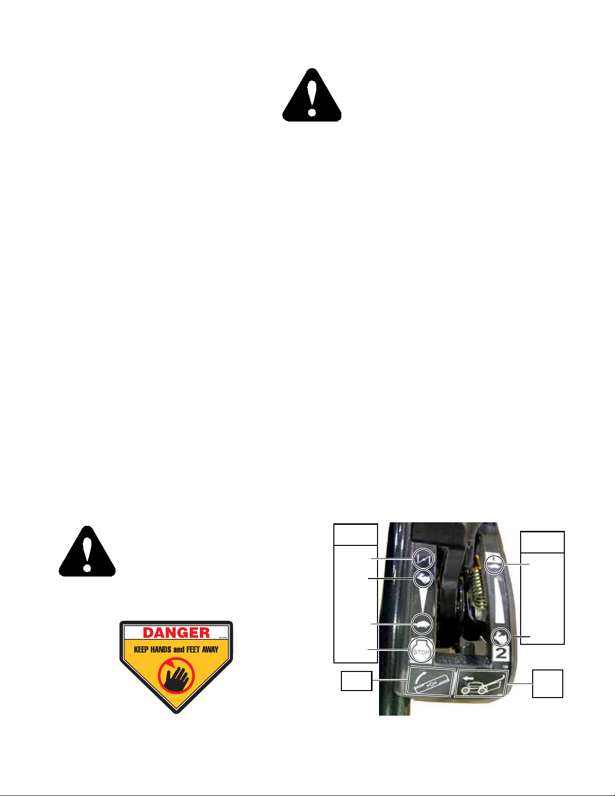
Safety and Instruction Decals
Specific safety warning decals are located on the equipment near the immediate areas of potential hazards. These decals should
not be removed or obliterated. Replace the decals if they become non-readable.
The following illustrations show the various decals that are located on the machine. A brief explanation is shown to help the operator
understand the meanings of these decals.
Throttle
lever
Choke
Fast
• Read Owner’s Manual and Quick Reference Decal before
attempting to operate this machine.
Slow
Stop
Blade
lever
Gearshift
lever
Slow
Fast
Drive
clutch
lever
• Whirling blades! Keep hands and feet away.
108548_0711 3-1
Page 10

WARNING:
Fire!
Read owner’s manual before
operating
• Do not smoke while refueling.
• Do not remove the fuel tank cap or fill with engine running or
while the engine is hot.
• Allow engine to cool before storing machine inside a building.
• Store away from open flame or spark if there is fuel in tank.
• Clean up any gasoline spills.
WARNING:
Thrown objects!
• Always maintain a safe
distance from people and
pets when mowing.
• Always stop machine if
someone enters the area.
• Read Operator’s Manual before attempting to operate this machine. Read Operator’s Manual before attempting to service
this manual.
• Wear ear protection, eye protection and
WARNING:
Carbon monoxide
poisoning
DANGER:
Rotating blades!
safety shoes when operating this equipment.
• Never run the engine in an enclosed area
unless exhaust is vented to the outside.
Exhuast gases contain carbon monoxide
which is an odorless and deadly poison.
• Keep shields and covers in
place while machine is in
operation
• Keep hands, feet and clothing
away from rotating blades.
• Disconnect spark
plug before servicing
WARNING:
Thrown
objects!
• Never operate the
mower deck with
guard altered,
removed or in
raised position,
except when the
entire grass
catcher attachment or mulching
system being used.
• Always maintain a
safe distance from
people and pets
when mowing.
• Always stop
machine if someone enters the area.
• Inspect area to be
mowed for hazards
such as rocks,
metal objects and
other debris which
may be thrown or
entangled by
mower blades.
Remove these
objects before
mowing.
WARNING:
Falling!
• Go across
slopes, not up
and down
• Before and while backing,
look behind and down for
small children and obsticles.
3-2 108548_0711
Page 11

OPERATION
Safe Operating Practices
This product is capable of amputating hands and feet and
throwing objects. Always follow all safety instructions to avoid
serious injury or death.
Operation Precautions
Never leave a running machine unattended. Always stop
on level ground, release blade lever and drive clutch lever
and set the throttle lever to the “STOP” position before
leaving machine for any reason including emptying the
catcher or unclogging the discharge chute.
Always keep safety shields and covers in place, except
for servicing.
Do not block the muffler outlet.
Always maintain a safe distance from people and pets
when mowing. Always stop machine and disengage the
blade if someone enters the area.
Always operate machine in daylight or with adequate
working lights.
Follow daily and weekly checklists, making sure blade is
tightly secured and bolts are tightened.
Always observe traffic laws while driving machine from
one location to another. Watch for traffic when operating
near or crossing roadways.
Always keep engine and machine clean, removing accu-
mulated dirt, trash and other material from machine.
Clean up oil or fuel spillage. Allow machine to cool
before storing.
Inspect area to be mowed for hazards such as rocks,
metal objects and other debris which may be thrown or
entangled by mower blades. Remove these objects before
mowing. Stay behind the handle when the engine is running.
Always be alert for hazards such as rocks, metal objects
and other debris which may be thrown or entangled by
mower blades. Watch out for holes or deep depressions.
Always wear adequate ear protection, such as earplugs,
when operating this equipment as prolonged exposure to
uncomfortable or loud noises can cause impairment or
loss of hearing. Do not wear radios or music headphones
while operating the machinery. Safe operation requires
your full attention.
Do not operate the equipment while wearing sandals, ten-
nis shoes, sneakers, shorts or any type of loose fitting
clothing. Long hair, loose clothing or jewelry may get
tangled in moving parts. Always wear long pants, safety
glasses, ear protection and safety shoes when operating
this machine.
Always inspect machine for damage after striking a for-
eign object. If damage is found, repair machine immediately. Be sure to stop on level ground, release blade lever
and drive clutch lever and set the throttle lever to the
“STOP” position when leaving operator’s position to
inspect damage. Disconnect the spark plug wire before
checking the blades, being careful to not touch the hot
engine or muffler.
Do not pull machine backward unless absolutely neces-
sary. Always look down and behind before and while
moving backward. Always be aware of what is behind
the machine before backing up.
Never operate a poorly maintained machine.
Never allow persons to operate this machine without
proper instruction or allow children to operate machine.
Allow only responsible adults who are familiar with
these instructions to operate this machine.
Never put hands or feet under any part of the machine
while it is running. Keep clear of the discharge opening at
all times.
Stop the engine before changing the cutting height.
Never direct discharge of material from mower deck
towards bystanders. Do not operate the mower without
either the entire mulching system (spacer, stand/stopper
and plug) or the entire grass collection system in place.
Always disengage the blades and wait for them to stop
before crossing gravel drives, walks or roads.
Always keep clear of the mower blades and attachments
during their operation.
Turn off blades when not mowing.
Slow down before turning.
Stop the engine before removing the grass catcher or
unclogging the discharge chute. Never clear the discharge
chute with the engine running. Turn off the engine and be
sure the blades have stopped before cleaning. Disconnect
the spark plug wire before cleaning, being careful to not
touch the hot engine or muffler. Use a stick to clear a
plugged discharge area. Never use your hand!
Do not operate the machine while under the influence of
alcohol or drugs.
Never operate the mower in wet grass as you may slip
and fall. Always be sure of your footing; walk; never run.
Never lift the machine while the engine is running.
Exercise caution when loading or unloading the machine
onto a trailer or truck. Use two people to lift unit.
Always wear safety goggles or safety glasses with side
shields when operating the mower.
Data indicates that operators, age 60 years and above, are
involved in a large percentage of mower-related injuries.
These operators should evaluate their ability to operate
the mower safely enough to protect themselves and others from serious injury.
Never make sudden starts, stops, turns, or reverse direc-
tion, especially when maneuvering on slopes.
Clean flammable material from machine. Prevent
fires by keeping the mower clean of accumulated
trash, grass clippings and other debris. Always clean
up spilled fuel and oil.
108548_0711 4-1
Page 12

Slope Operation
Slopes are a major factor in slip and fall accidents, which
can result in severe injury or death. All slopes require extra
caution. If you feel uneasy on a slope; do not mow it.
Use extreme caution when operating on slopes.
• Be extremely careful changing directions on a slope.
Slow down.
• Do not operate where the machine could slip or tip.
Always be sure of your footing. Keep a firm hold on the
handle and walk—never run.
Watch for holes, ruts or bumps. Uneven terrain could
overturn the machine. Tall grass can hide obstacles.
Remove obstacles such as rocks, tree limbs, etc.
Keep all movement on slopes slow and gradual. Do not
make sudden changes in speed or direction.
Avoid starting and stopping on a slope. If wheels lose
traction, disengage the blade and, using extreme caution,
proceed slowly off the slope.
Do not mow near drop-offs, ditches, or embankments.
The machine could suddenly turn over if a wheel goes
over the edge of a cliff or ditch, or if an edge caves in.
You could lose your footing or balance.
Do not mow on wet grass. Reduced traction could cause
sliding.
Terrain conditions can affect traction resulting in possible
loss of control of the machine. Some of the conditions to
be aware of are:
1. Wet terrain
2. Depressions in the ground; i.e. holes, ruts, washouts
3. Mounds of dirt
4. Soil type; i.e. sand, loose dirt, gravel, clay
5. Grass type, density, and height
6. Extremely dry conditions of grass
Another consideration to safe mowing on slopes is to
be aware of what is located at the bottom of the slope.
Extreme caution should be used when there is a hazard
located at the bottom of the slope. Some examples are:
1. Water; i.e. lake, river
2. Cliffs, retaining walls
3. Roads, highways
4. Buildings
5. Rocks
These are just a few examples of situations when caution must be used when operating on a slope. There are
many other possibilities too numerous to mention. Just
remember to always exercise extreme caution when operating on any slope.
Children
Tragic accidents can occur if the operator is not alert to
the presence of children. Children are often attracted to the
machine and the mowing activity. Never assume that
children will remain where you last saw them.
Never leave machine unattended with children present.
Children or bystanders may be injured if they move or
attempt to operate the mower while it is unattended.
Always release blade lever and drive clutch lever and set
the throttle lever to the “STOP” position before leaving
machine for any reason.
Keep children out of the mowing area and under the
watchful care of a responsible adult other than the operator.
Be alert and turn the machine off if children enter the
area.
Before and while backing, look behind and down for
small children.
Never carry children, even with the blade off. They may
fall off and be seriously injured or interfere with safe
machine operation.
Never allow children to operate the machine.
Use care when approaching blind corners, shrubs, trees,
the end of a fence or other objects that may obscure
vision or block your view of a child.
4-2 108548_0711
Page 13
Assembly
NOTE: This mower is to be set up in one of two modes, either catcher mode or mulching mode.
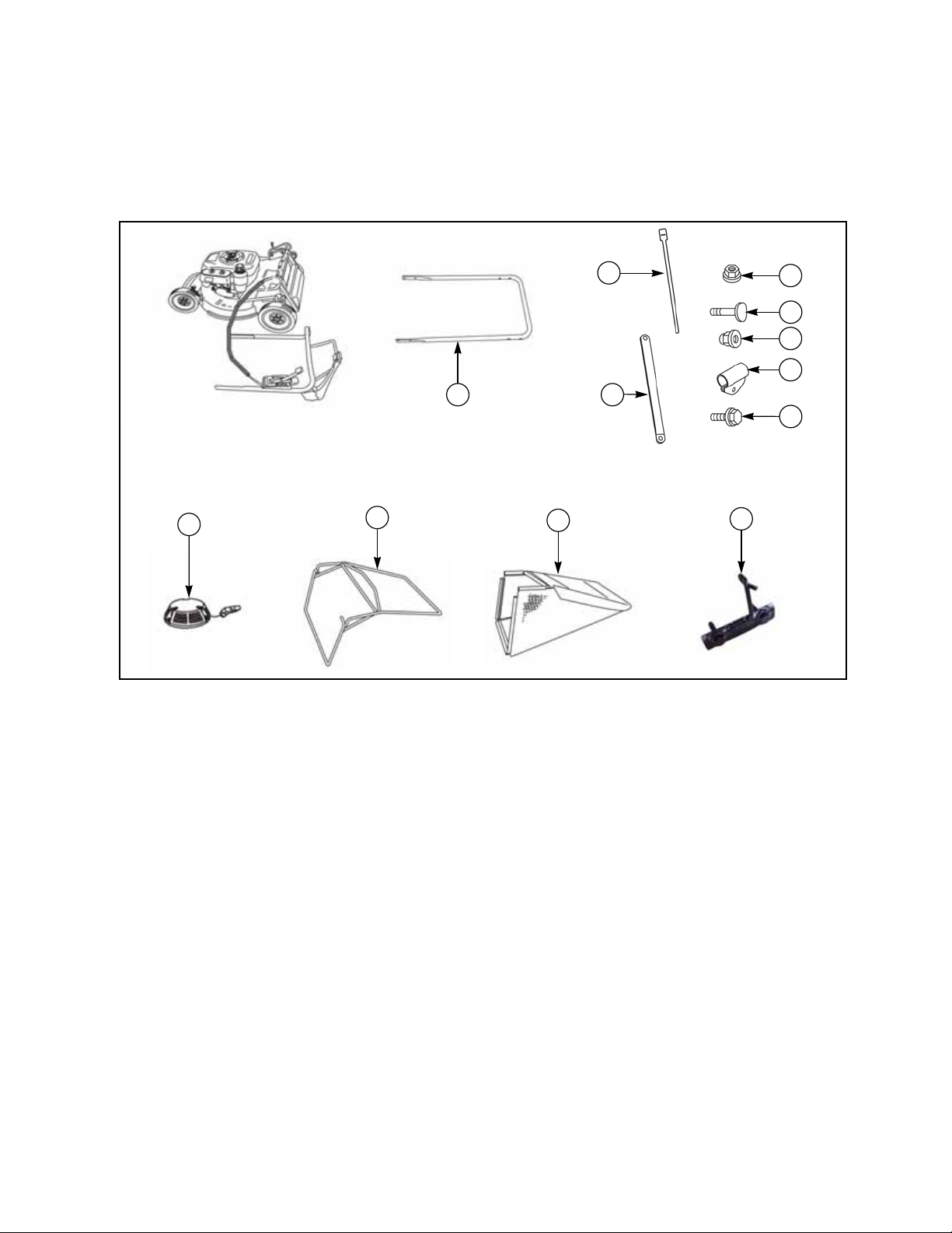
A. Parts List
Listed below are parts included in shipping carton. If any parts are missing or damaged, please contact Hustler Parts
Department
1. Remove the mower from shipping carton and verify that all the accessories not attached to the mower are accounted for as
shown on parts list. Fig. 4-1
12
3
11
Mower with upper
handle
2
4
5
13
Fig. 4-1
Item P/N Description Qty
1 929208 Mower 1
2 N/A Recoil starter (supplied with engine) 1
3 51027-268-103 Lower handle 1
4 11062-178 Frame 1
5 36098-155 Grass bag 1
6 569L-0800 Nut 4
7 583L-0800 Nut 6
8 31057-181 Cap screw 4
9 31057-256 Bolt 2
10 11012-132 Handle support clamp 2
11 71900-846 Handle support bar 2
12 68028-119 Velcro strap 3
13 71285-109 Recoil starter Handle 1
14 601399 Instruction manual 1
15 601825 Instruction manual (Engine) 1
16 Mulch kit (see page 4-5 for parts listing) 1
6
9
7
10
8
108548_0711 4-3
Page 14
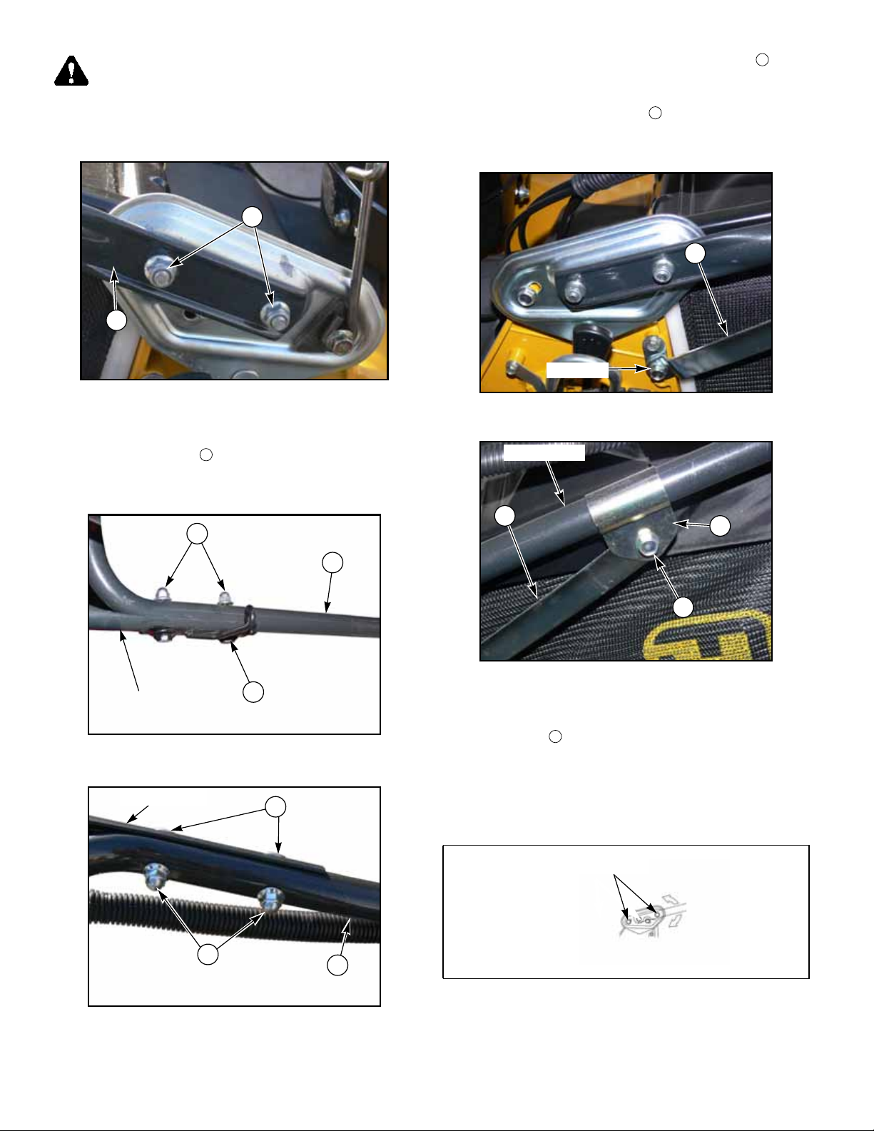
WARNING: Mower blades are sharp and can cut.
Wrap the blade(s) or wear gloves and use extra caution
when servicing them.
1. Attach the lower handle to the mower with flanged
nuts. Fig. 4-2
6
3
3. Remove the lower bolt and attach the bar to the
11
mower as shown. Fig. 4-5. Start the bolt in the hole
but do not tighten. Install the bracketto the lower
handle and attach the bar using hardware and
11
(flanged cap nutnot shown). Tighten all of the hardware. Fig. 4-5 and Fig. 4-6
11
Lower bolt
Fig. 4-2
2. Assemble the upper handle to the lower handle .
Use the holder on the right hand side and the two
13
bolts on the left hand side and the flanged cap nuts
.Fig. 4-3 and Fig. 4-4
7
3
Upper handle
13
Fig. 4-3
Upper handle
9
Fig. 4-5
Lower handle
11
10
8
Fig. 4-6
NOTE: When adjusting the height of the handle, loosen the
bolt on the bar , before loosening the handle height adjust-
11
ment bolt. Fix the cable harness to the handle with velcro
straps so that they do not interfere with the opening / closing
of the guard or operation of the machine. The cable harness
should be routed under the lower handle. Fig. 4-7 and
Fig. 4-8
7
Fig. 4-4
Loosen bolts to
adjust height
3
Fig. 4-7
4-4 108548_0711
Page 15
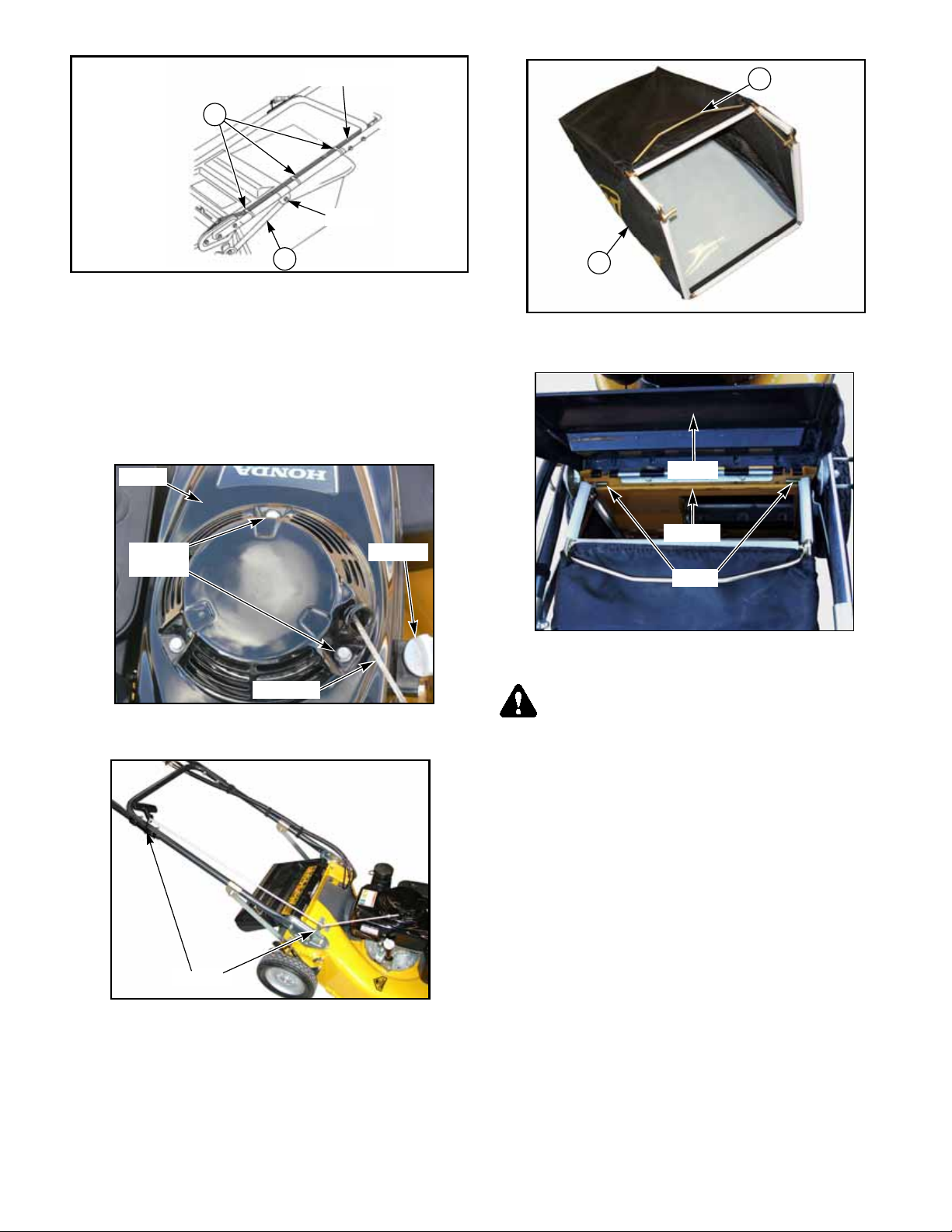
12
Cable harness
Loosen
4
11
Fig. 4-8
4. Attach the recoil starter to the mower. Remove the
three existing cap screws on the cover. Align recoil
starter so that the draw cord is on the dipstick side of
the engine. Bolt recoil starter and cover to the
engine. Route the cord through the holders provided
on the lower right hand side handle. Fig. 4-9 and
Fig. 4-10.
Cover
Existing
hardware
Draw cord
Dispstick
Fig. 4-9
5
Fig. 4-11
Guard
Housing
Hook
Fig. 4-12
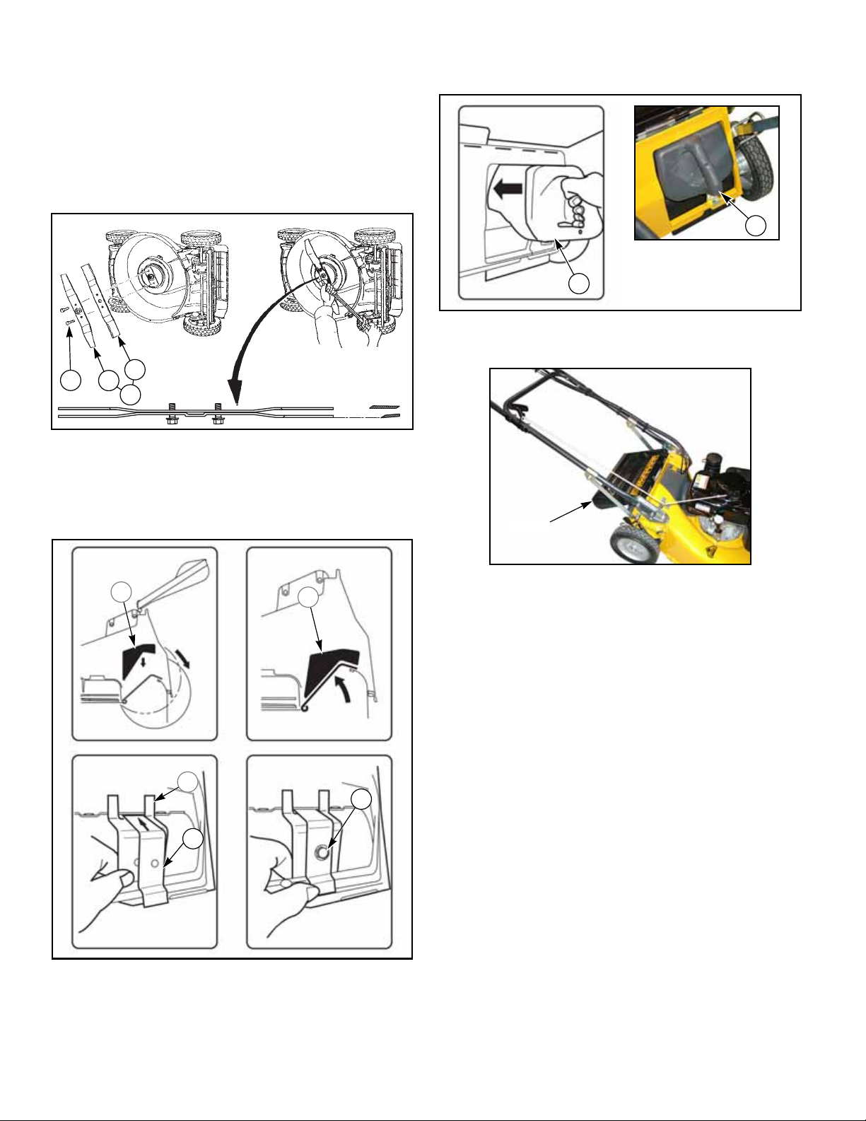
WARNING: When attaching or detaching the catcher,
be sure to turn off the engine. Open or close the guard
slowly. Also, do not place your finger(s) between the
guard and the mower.
Holders
Fig. 4-10
5. Place the catcher bag onto the frame . Fig. 4-11.
Attach the catcher to the mower. Lift the guard and set
the hooks of the catcher on the housing of the mower.
To remove the catcher reverse the previous procedure.
Fig. 4-12
108548_0711 4-5
NOTE: Before operating the mower, oil and unleaded gaso-
line need to be added to the engine. Add 1.4 pints (.65 L) of
SAE 10W-30 oil and a half gallon (1.8 L) of gasoline to the
engine.
B. Mulch kit
Item
P/N Description
1 71906-460 Multi cutting blade set 2
2 91014-183 Blade 1
3 91014-182 Blade 1
4 11024-150 Clip 1
5 11086-198 Clip (stopper) 1
6 31044-134 Plug 1
7 60124-220 Spacer 1
8 31057-220 M10 x 30 x 1.25 2
9 335L-0610 M6 x10 x 1.0 1
Qty
NOTE: Do not operate in conditions that cause the engine to
bog down or stall. When cutting thick grass, or high grass,
adjust the cutting height of the deck to a suitable setting. It
Page 16
may be necessary to make more than one pass to properly cut
a lawn.
1. Turn the mower off and shutoff the fuel cock. Discon-
nect the spark plug wire. Turn the mower on its side.
Fuel tank side must be facing up.
2. Remove the normal cutting blade and replace with
mulching blades . Use the bolts supplied with the
mulching blades. The regular bolts will be too short.
Torque blades to 26 - 33 ft.-lb. (35-45 Nm). Fig. 4-13
4. Insert the plug and allow the guard to return to the
normal operating position. Fig. 4-15 and Fig. 4-16
6
6
Fig. 4-15
8
3
2
1
Torque blade bolt to
26–33 ft.-lbs.
(35 –45 Nm)
Fig. 4-13
3. Lift guard and place the spacer in the discharge
chute. Install and bolt the two clips and
together as shown. Fig. 4-14
7
7
Guard
Fig. 4-16
4
5
Fig. 4-14
9
4-6 108548_0711
Page 17
U
G
J
K
L
M
T
H
P
O
W
N
B
A
V
F
H
I
C
D
E
Q
ON
OFF
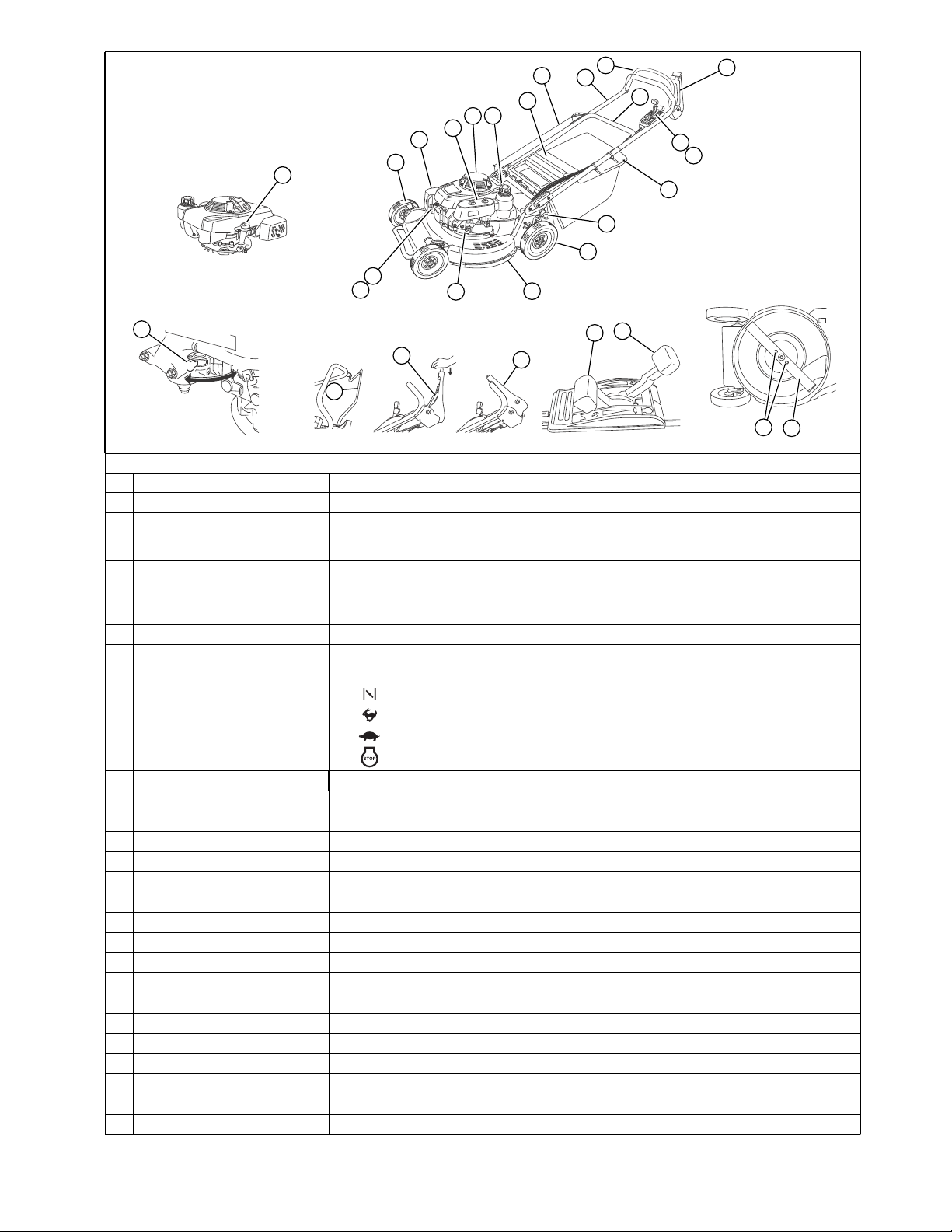
NOTE: Illustrations may differ from the actual machine you have purchased.
Name Description
Upper handle Grab this handle when using the lawn mower
A.
Drive clutch lever
B.
Blade lever
C.
Gearshift lever Adjusts the mowing speed
D.
Throttle lever
E.
Grass bag Catches the grass clippings
F.
Guard
G.
Cutting height adjustment lever Adjusts the cutting height (one located at each wheel)
H.
Wheel
I.
Fuel tank
J.
Recoil starter Pull the starter rope to start the engine
K.
Air cleaner
L.
Muffler
M.
Housing
N.
Spark plug
O.
Spark plug wire
P.
Fuel cock Shuts off fuel flow to the engine.
Q.
Blade
R.
Blade mounting bolts Attaches the blade to the blade mount
S.
Engine oil dipstick & oil fill tube Shows the engine oil level.
T.
Starter rope
U.
Lower handle
V.
Fuel filter
W.
B
Controls mowing and stoppage.
Pushed forward: Machine starts moving forward
Released: Machine stops moving forward
Engages and disengages the blade clutch
Pushed forward with yellow button depressed: Engages the blade clutch
(When pushed forward with the button not depressed, the blade does not rotate.)
Released: Stops the blade rotation.
Adjusts the engine speed.
(Position)
C
C
(Meaning)
Choking
High speed
Low speed
Stop
Fig. 4-17
D
E
S
R
(Usage)
Engine start
Mowing
Idling
Engine stop
108548_0711 4-7
Page 18

Operation
WARNING: Before inspection, stop the engine and
remove the spark plug wire from the spark plug.
A. Preparation and inspection
1. Place the mower on a level surface.
2. Check the engine oil level using the engine oil dip-
stick. Do not screw dipstick into tube when checking
engine oil. Make sure the oil level is between the
upper and lower limits on the dipstick. Replenish oil if
necessary. Make sure the dipstick is properly seated
when reinstalled in the dipstick housing. Fig. 4-18
3. Check the fuel level and fill fuel tank if necessary.
Make sure the fuel cap is screwed on properly and
tight before beginning operation. Fig. 4-19
4. If catching: Check the grass bag for any holes or
damage. Replace if damaged.
If mulching: Check that the spacer, stand/stopper and
plug are in place and the guard is in the lowest
position and is resting against the plug.
5. Check the machine for loose hardware or parts. Make
sure all covers and guards are properly installed.
6. Check the mower blade for damage and proper blade
bolt torque. Replace blade if damaged. Refer to
Mower Blade Maintenance section for more detailed
information.
4. Crumple a half sheet of newspaper into a ball small
enough to go under the deck (approximately 3” or
7.6cm in diameter).
5. Place the newspaper ball 5” (12.7cm) in front of the
mower.
6. Start the engine.
7. Engage the blade lever to start the blade.
8. After the blade is spinning, disengage the blade lever.
You should hear a change in the noise the mower is
making. This will be due to the blade stopping and the
engine sound increasing because no load is being
applied to it.
9. Immediately push the mower over the newspaper ball.
10.Stop the engine and wait for all moving parts to stop.
11.Walk around the mower to check for the newspaper
ball. If the ball did not go under the mower then repeat
steps 5 through 10.
12.Move the mower away from the newspaper ball. If the
newspaper ball has unraveled or is shredded, the blade
is not stopping properly, resulting in unsafe operating
conditions. Contact your Hustler Turf Dealer before
continuing operation.
C. Engine operation
1. Attach the spark plug wire to the spark plug.
2. Set the fuel cock to the “ON” (open) position.
Fig. 4-20
Dipstick
Fig. 4-18
Fuel cap
Fig. 4-19
B. Checking the Blade Brake Clutch safety system
Check the blade brake clutch safety system daily,
prior to each use. This system is an important mower
safety feature. It should be repaired immediately if it
malfunctions.
1. Stop the engine and wait for all moving parts to stop.
2. Move the mower onto a paved surface that is located
in a non-windy area.
3. Set the cutting height to 2-1/2” (6.4cm) at all four
wheels.
ON
Fig. 4-20
3. Set the throttle to the “CHOKE” position if starting a
cold engine. Set the throttle to the “FAST” position if
the engine is warm. Fig. 4-21
Throttle lever
(choke position)
Fig. 4-21
4. To start the engine: Lightly pull on the starter rope
handle until you can feel resistance. Make sure you
have a good grip on the handle and then pull on the
starter rope handle with more force. After engine has
started allow the starter rope to return to the recoil
starter handle slowly.
4-8 108548_0711
Page 19

NOTE: Make sure that the blade lever and the drive clutch
lever are disengaged before starting the engine.
WARNING: Make sure there is no person or object in
front of, or behind you when pulling on the starter
rope.
5. Allow the engine to warm up before mowing. Set
throttle lever to the “FAST” position when mowing.
Fig. 4-22
NOTE: The engine may stall if the blades are engaged with
the throttle in the “SLOW” position.
Throttle lever
(fast position)
Fig. 4-22
between 40o and 105o F (5o and 40o C). Failure to use
this machine within this temperature range may result in
a malfunction, breakdown or accidents.
WARNING: All operators and mechanics must
become familiar with the safe operation of the equipment, operator controls and safety signs before using
this machine.
1. Perform the daily inspection and preparation routine
found elsewhere in this manual before starting operation.
2. Start engine per the Engine Operation section.
3. Set the throttle lever to the “FAST” position. Fig. 4-25
Throttle lever
6. To stop the engine: Release the blade lever and the
drive clutch lever. Set throttle to the “STOP” position.
When engine has stopped, rotate the fuel cock to the
“OFF” (closed) position. Fig. 4-23 and Fig. 4-24
NOTE: Do not stop the engine with the throttle set in the
“CHOKE” position. Restarting the engine will become
harder if this occurs. However, if the engine will not stop
with the throttle set to the “STOP” position then set the throttle to the “CHOKE” position to shutoff the engine. If the
“CHOKE” method is necessary to stop the engine, check the
throttle control for proper adjustment. Re-adjust if necessary.
Throttle lever
(stop position)
Fig. 4-23
OFF
Fig. 4-25
4. Push the blade lever forward while pressing on the
yellow button. This will engage the blade clutch.
Make sure the lever is pushed forward until it touches
the handle. Fig. 4-26
NOTE: The blade will not engage unless the yellow button
is depressed.
Yellow
button
Blade disengaged
Blade lever
Blade engaged
Fig. 4-26
5. To drive the mower forward: Step toward the han-
dle while pushing the drive clutch lever forward to
engage the transmission. Make sure the lever is
pushed forward until it touches the handle. Fig. 4-27
IMPORTANT: Do not require the machine to pull
you forward. This will result in premature transmission failure.
Fig. 4-24
D. Mowing operation
When operating this mower observe the instructions and
safety items in this manual.
Use this mower when the outside air temperature is
108548_0711 4-9
Page 20

Drive
clutch
lever
Fig. 4-27
6. Adjust the mowing speed with the gearshift lever.
Fig. 4-28
NOTE: Adjust the mowing speed according to the conditions of the mowing area and the grass.
WARNING: To mow; make sure each the blade lever
and clutch lever are pushed down until they touch the
handle. Continuing to operate without the levers
pushed completely down will result in a machine fail-
ure.
Slow Fast
3. Place the cutting height adjustment lever in the
desired cutting height notch.
4. Set all cutting height adjustment levers at the same
position
F. Grass catcher
1. Attaching the grass catcher:
Lift the guard and place the catcher hook onto the
mower housing. Fig. 4-32
2. Removing the grass catcher:
Lift the guard and remove the catcher hook from the
mower housing.
Close the guard slowly.
NOTE: If the grass catcher becomes full or the discharge
opening becomes clogged then the mower will begin to leave
grass clippings.
NOTE: Clogging may occur if the grass catcher bag
becomes wet..
Lever
Notch
Lever
Gearshift
lever
Fig. 4-28
7. To shutdown the mower do the following:
Release the drive clutch lever and pull back on the
blade lever to disengage the blade clutch. Set the
throttle to the “STOP” position. The engine should
stop. Fig. 4-29
Throttle lever
Fig. 4-29
E. Cutting height adjustment
WARNING: Hot engine and muffler! Do not touch
the muffler and the engine when adjusting the cutting
height.
1. Stop the engine.
2. Push the cutting height adjustment lever so that it
clears the height setting notches. Fig. 4-30 and
Fig. 4-31
Hook
Fig. 4-30
Fig. 4-31
Mower
housing
Fig. 4-32
Notch
Lever
Notch
Guard
Hook
4-10 108548_0711
Page 21

Transporting the mower
1. Close the fuel cock.
2. If necessary detach the handle. Temporarily tighten
the screws at the original positions if the handle is
detached.
WARNING: Stop the engine and remove the spark
plug wire before loading the mower onto a truck or
trailer.
WARNING: Do not leave nor transport this machine
tilted.
108548_0711 4-11
Page 22

4-12 108548_0711
Page 23

MAINTENANCE & ADJUSTMENTS
Safe Servicing Practices
This product is capable of amputating hands and feet and
throwing objects. Always follow all safety instructions to avoid
serious injury or death.
Service
Unless specifically required, DO NOT have engine run-
ning when servicing or making adjustments to the
mower. Park the machine on level ground. Disconnect
the spark plug wire from the spark plug before doing any
maintenance. Wait for all movement to stop before
adjusting, cleaning or repairing. Repairs or maintenance
requiring engine power should be performed by trained
maintenance personnel only. To prevent carbon monoxide poisoning, be sure proper ventilation is available
when engine must be operated in an enclosed area. Read
and observe safety warnings in this manual.
Before working on or under the deck, make certain
engine cannot be accidentally started. Shut engine off and
disconnect spark plug wire from the spark plug for maximum safety. Repairs or maintenance requiring engine
power should be performed by trained maintenance personnel only.
Always keep shields and covers on mower for safety as
well as cleanliness.
Use a stick or similar instrument to clean under the
mower making sure that no part of the body, especially
arms and hands are under mower.
Always keep engine and machine clean, removing accu-
mulated dirt, trash and other material from machine.
Clean up oil or fuel spillage. Allow machine to cool
before storing.
Clean flammable material from machine. Prevent
fires by keeping the mower clean of accumulated
trash, grass clippings and other debris. Always clean
up spilled fuel and oil.
Always wear adequate eye protection when servicing the
mower or when grinding mower blades and removing
accumulated debris.
Use extra caution when handling gasoline and other
fuels. They are flammable and vapors are explosive.
Never attempt to start engine when there is a strong odor
of gasoline fumes present. Locate and correct cause.
Never remove fuel cap or refuel mower while engine is
running or while engine is hot; never refuel near an open
flame or near devices which can create a spark. Refuel
outdoors. Clean up any gasoline spills.
Never run the engine in an enclosed area unless exhaust
is vented to the outside. Exhaust gases contain carbon
monoxide which is an odorless and deadly poison.
Never attempt to make any adjustments or repairs to the
drive system or mower deck while the engine is running
or deck clutch is engaged. Mower blades cannot be seen
and are located very close to the deck housing. Fingers
and toes can be cut off instantly. Repairs or maintenance
requiring engine power should be performed by trained
personnel only.
Prior to any servicing stop the engine and disconnect the
spark plug wire, being careful to not touch the hot engine
or muffler.
Be careful not to spill fuel or oil when tilting the unit to
check or maintain the blade. Clean up any spills immediately.
Do not touch hot parts of machine. Allow engine to cool
before servicing.
Keep nuts and bolts tight, especially the blade attachment
bolts. Keep equipment in good working condition.
Never tamper with safety devices. Check their proper
operation regularly.
Stop the engine before removing the grass catcher or
unclogging the discharge chute. Never clear the discharge
chute with the engine running. Turn off the engine and be
sure the blade has stopped before cleaning. Use a stick to
clear a plugged discharge area. Never use your hand!
Grass collection system components are subject to wear,
damage and deterioration, which could expose moving
parts or allow objects to be thrown. Frequently check
components and replace with manufacturer’s recommended parts, when necessary.
Exercise caution when working under the deck as the
mower blade is extremely sharp. Wrap the blade(s) or
wear gloves and use extra caution when servicing them.
Use only genuine Hustler replacement parts to ensure that
original standards are maintained
Introduction
Regular maintenance is the best prevention for costly
downtime or expensive, premature repair. The following pages
contain suggested maintenance information and schedules
which the operator should follow on a routine basis.
Remain alert for unusual noises, they could be signaling a
problem. Visually inspect the machine for any abnormal wear or
damage. A good time to detect potential problems is while
performing scheduled maintenance service. Correcting the
problem as quickly as possible is the best insurance.
Clear away heavy build-up of grease, oil and dirt, especially
around the engine; minute dust particle are abrasive to closetolerance engine assemblies.
Daily inspect mower for grass clippings and wire and string
tangles. The underside of the mower deck will collect a build-up
of grass clippings and dirt, especially when grass is wet or has
high moisture content. This build-up will harden, restricting
blade and air movement and will probably show a poorer quality
of cutting. Therefore it should be removed routinely.
To do this it will be necessary to scrape the build-up from
underneath.
Some repairs require the assistance of a trained service
mechanic and should not be attempted by unskilled personnel.
Consult your Hustler service center when assistance is needed.
108548_0711 5-1
Page 24

Torque values
WARNING: Particular attention must be given to
tightening the blade bolts. Failure to correctly torque
these may result in the loss of a blade, which can cause
serious damage or personal injury.
Torque values are given below:
Ft-lbs. Nm
Blade spindle bolt top ...................26 - 33..........35 - 45
When practical, remove gas-powered equipment from
the truck or trailer and refuel the equipment with its
wheels on the ground. If this is not possible, then
refuel such equipment on the truck or trailer using a
portable container and not a gasoline dispenser nozzle. If a gasoline dispenser nozzle must be used, keep
the nozzle in contact with the rim of the fuel tank or
container opening at all times until fueling is complete. Do not use a nozzle lock-open device.
Read and observe safety precautions elsewhere in this
manual.
For all other torques refer to the standard torque chart found
elsewhere in this manual.
For engine torque values, see engine owner’s manual.
Washing the mower
When washing the mower, do not use a power washer. This
will help prevent water intrusion and ensure component
performance. Wipe with a dry rag after washing and then wipe
the metal surface with a rag soaked with oil.
Clean the grass catcher with water and allow it to dry before
using.
Fuel system
DANGER: To avoid personal injury or property
damage, use extreme care in handling gasoline.
Gasoline is extremely flammable and the vapors
are explosive.
DANGER: Observe usual fuel handling precautions:
Do not smoke while refueling. Extinguish all cigarettes, cigars, pipes and other sources of ignition.
Do not remove fuel cap or fill tank with engine running or while engine is hot. Clean up any gasoline
spills.
Allow engine to cool before storing machine inside a
building.
Keep fuel away from open flame or spark and store
machine away from open flame or spark or pilot light
such as on a water heater or other appliances.
Use extreme care when handling gasoline and other
fuels. They are extremely flammable and vapors are
explosive. A fire or explosion from gasoline can burn
you and others and can damage property.
Never refuel or drain the fuel from the machine
indoors.
Never attempt to start engine when there is a strong
odor of gasoline fumes present. Locate and correct
cause.
Store gasoline in an approved container and keep it
out of the reach of children. Never buy more than a 30
day supply of gasoline.
Always place gasoline containers on the ground away
from your vehicle before filling.
Do not fill gasoline containers inside a vehicle or on a
truck or trailer bed with interior carpets or plastic
truck bed liners. Always place gasoline containers on
the ground away from your vehicle before filling.
WARNING: Gasoline is harmful or fatal if swallowed.
Long-term exposure to vapors can cause serious
injury and illness.
Avoid prolonged breathing of vapors.
Keep face away from nozzle and gas tank or fuel container opening.
Keep gas away from eyes and skin.
If fuel is spilled on clothing, change clothing immediately.
WARNING: Never overfill fuel tank. Replace gas cap
and tighten securely.
The fuel tank is located at the left rear of the engine. Fig. 5-1
Use regular unleaded gasoline with an octane rating of 87 or
higher.
IMPORTANT: Dispose of any unused gasoline properly
according to the law in each country.
IMPORTANT: Never use methanol, gasoline containing
methanol, or gasohol containing more than 10% ethanol because
the fuel system could be damaged. Do not mix oil with gasoline.
Fuel tank
Fig. 5-1
Engine oil and filter
IMPORTANT: Drain all of the gasoline from the fuel tank
before tilting the engine to drain the oil. Dispose of used engine
oil properly according to the law in each country.
IMPORTANT: All oil drips or spills must be cleaned off of
the exhaust system before operating the machine.
WARNING: Do not touch the engine and muffler as
they may be hot.
1. Remove the engine oil dipstick.
2. Remove the engine oil drain plug. Fig. 5-2
3. Tilt the mower onto it’s side to drain the oil. Fig. 5-2
4. Set the mower right side up and replace the oil drain plug.
Clean up any oil spill.
5. Fill engine with the proper oil and quantity per the engine
5-2 108548_0711
Page 25
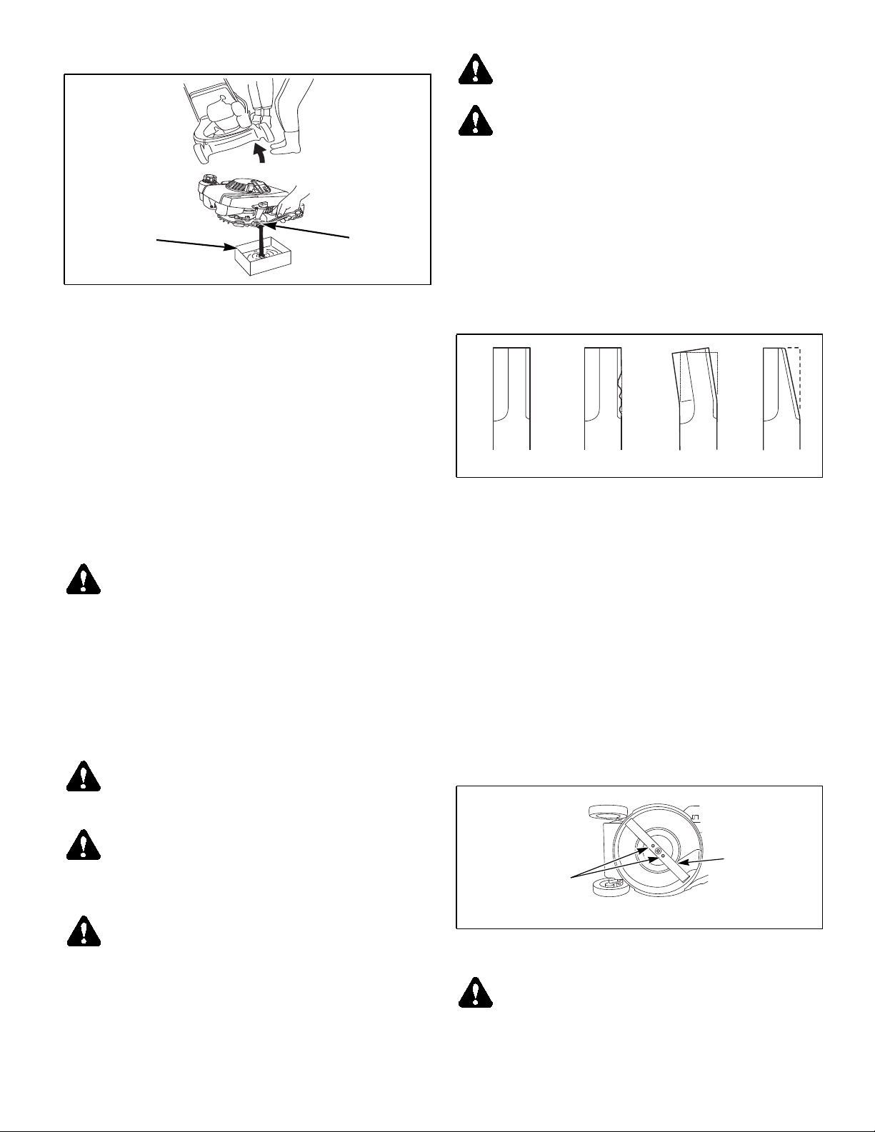
manufacturer’s recommendation.
Oil pan
Oil drain
plug
Fig. 5-2
Engine air filter
Perform engine air filter maintenance per the engine’s
owner’s manual.
General engine maintenance
Detailed instructions and recommendations for break-in and
regular maintenance are specified in the Engine Owner’s
manual. Please refer to this manual for engine servicing,
lubricating oil levels with quality and viscosity
recommendations, bolt torques, etc. The engine warranty is
backed by the manufacturer. Special attention should be paid to
applicable data which will not be duplicated here.
WARNING: Do not change engine governor setting
or overspeed the engine.
Mower blade maintenance
Check the mower blade daily, it is the key to power efficiency
and well groomed turf. Keep it sharp, a dull blade will tear
rather than cut the grass, leaving a brown ragged top on the
grass within a few hours. A dull blade also requires more power
from the engine.
Replace any blade which is bent, cracked or broken.
WARNING: Mower blades are sharp and can cut.
Wrap the blade(s) or wear gloves and use extra caution
when servicing them.
WARNING: Always wear adequate eye protection
when grinding mower blades.
WARNING: Failure to correctly torque the blade
mounting bolts may result in the loss of the blade
which can cause serious injury.
A. Checking the blade
1. When checking the blade, lay the mower on it’s side
with the carburetor on the upside.
2. Confirm that the blade is not chipped, bent or worn.
Fig. 5-3
3. If the blade or the blade bolts are damaged, replace
with Hustler approved parts.
4. Torque the blade bolts to 26.0-33.0 ft.-lbs
(35-45 Nm). Fig. 5-4
New blade Chip Bend Wear
Fig. 5-3
B. Replacing the blade
1. Lay the mower on it’s side with the carburetor on the
upside.
2. Loosen the blade mounting bolts and remove the
blade.
3. Clean the underneath side of the mower housing and
around the blade mounting bracket.
4. Attach blade using the blade mounting bolts and
torque between 26 - 33 ft.-lbs (35 - 45 Nm). Fig. 5-4
NOTE: Check the blade for balance following grinding. A
commercial balancing tool is available through most hardware
supply stores, or balancing can be done by placing the blade on
an inverted line punch. Blade should not lean or tilt. Spin the
blade slowly, blade should not wobble. If blade is out of balance, true it up before reinstalling.
WARNING: Never attempt to straighten a bent blade
by heating, or weld a cracked or broken blade as the
blade may break and cause serious injury. Replace
worn or damaged blades.
DANGER: Never work with blades while engine is
running. Always disconnect the spark plug wire from
spark plug when working under the mower. Wear
gloves when handling blades. Always check for
blade damage if mower strikes a rock, a branch or
other foreign objects during mowing!
108548_0711 5-3
Bolts
Torque to
26 - 33 ft.-lbs.
(35 - 45 Nm)
Blade
Fig. 5-4
WARNING: Mower blades are sharp and can cut.
Wrap the blade(s) or wear gloves and use extra caution
when servicing them.
Page 26

Throttle lever adjustment
Adjust the throttle lever so that when it is placed in the
“CHOKE” position the engine choke is engaged. Fig. 5-5
1. Confirm that the adjustment hole on the engine control
panel matches the throttle lever when it is in the “FAST”
position.
2. If adjustment is necessary, adjust by turning the adjuster
and loosening the lock nut on the throttle cable. Fig. 5-6
3. Set the adjuster to the optimal position and tighten the
lock nut. Fig. 5-6
4. Start the engine and confirm that the engine stops
completely when the throttle lever is set at the “STOP”
position.
Throttle lever
Fig. 5-5
Adjuster
Throttle
Lock nut
cable
Fig. 5-6
1.97” - 2.95”
Blade lever
(50 - 75 mm)
Fig. 5-7
Adjuster Lock nut
Blade
cable
Fig. 5-8
Drive clutch lever
Adjust so that the machine runs (when the drive clutch is
engaged) when the distance between the drive clutch lever and
the handle is 2.95” - 3.94” (75 - 100 mm). Fig. 5-9
1. If adjustment is necessary, adjust by turning the adjuster
and loosening the lock nut on the drive clutch cable.
Fig. 5-10
2. Set the adjuster to the optimal position and tighten the
lock nut. Fig. 5-10
3. Confirm that the machine can be pulled backward when
the drive clutch lever is released.
Blade lever adjustment
Adjust so that the blade starts rotating when the distance
between the blade lever and the handle is 1.97” - 2.95” (50 - 75
mm) when the yellow button is depressed. Fig. 5-7
1. If adjustment is necessary, adjust by turning the adjuster
and loosening the lock nut on the blade cable. Fig. 5-8
2. Set the adjuster to the optimal position and tighten the
lock nut. Fig. 5-8
3. Confirm that the blade stops completely when the blade
lever is released.
Drive clutch
lever
2.95” - 3.94”
(75 - 100 mm)
Fig. 5-9
Adjuster
Drive clutch cable
Lock nut
Fig. 5-10
5-4 108548_0711
Page 27

Gearshift lever
Adjust the gearshift lever to .04” - .51” (1 - 3 mm) as shown
in Fig. 5-11.
1. If adjustment is necessary, adjust by turning the adjuster
and loosening the lock nut on the gearshift cable.
Fig. 5-12
2. Set the adjuster to the optimal position and tighten the
lock nut. Fig. 5-12
3. Start the engine and confirm that the running speed
changes when the gearshift lever is operated.
Gearshift lever
.04” - .51”
(1-3mm)
Fig. 5-11
Adjuster
Lock nut
Gearshift
cable
Fig. 5-12
108548_0711 5-5
Page 28

Hustler M-1
Maintenance Schedule
SERVICE AT
INTERVALS INDICATED
Verify safety start interlock system Prior to each use
Visually inspect unit for loose
hardware and/or damaged parts
Check oil level, engine (1) Prior to each use or every 4 hours
Clean air intake screen (3) Prior to each use or every 4 hours
Clean foam element (3) Prior to each use
Check fuel level Prior to each use
Blade - sharpen & securely
fastened
Grass catcher/mulcher plug -
securely in place
Clean engine and housing Daily
Change engine oil & filter (1)(2) X
Clean cylinder & head fins (a) X
Clean engine exterior (a) X
Replace air cleaner paper element
(3)
Clean & regap spark plug (a) X
Check fuel line (4) X
Change fuel filter X
Replace spark plug X
Throttle cable - adjust X
Drive clutch cable - adjust X
Blade cable - adjust X
Gearshift cable - adjust X
WEEKLY
OR 40
HOURS
Prior to each use
Prior to each use
Prior to each use
X
ANNUALLY
OR 100
HOURS
NOTES:
1. Initial oil change is after 5 hours of operation. Thereafter,
change oil after every 40 hours operation. Change more
often under dusty or dirty conditions and during hot
weather periods.
2. Change engine oil filter per the engine manufacturer’s
recommendations. Refer to Engine Owner’s Manual for
recommendations and other maintenance items.
3. Service more often under dusty or dirty conditions.
4. Check fuel line hose for any cracks or leaks
REFERENCES:
a—Refer to Engine Owner’s Manual
NOTE: After completing maintenance cycle (100 hours), repeat
cycle.
TROUBLESHOOTING
The majority of operating problems that occur with a system can be traced to
improper adjustments or delayed service. A consistently applied preventative
maintenance program, as outlined in the maintenance section of this manual, will
prevent many problems. The following chart is designed to help you locate a
problem by suggesting probable causes and the recommended solutions.
SYMPTOMS PROBABLE CAUSES
No fuel or line plugged Fill tank or replace line
Engine oil low Add engine oil
Throttle lever is set to
Engine does not
start
Engine is hard to
start
Engine power is
weak
Engine overheating
Abnormal vibration
“STOP” position
Spark plug wire is
disconnected
Excess gasoline is
inhaled into cylinder
Air cleaner is dirty Clean or replace air filter
Air cleaner is dirty Clean or replace air filter
Carburetor is clogged Clean carburetor
Fuel tank cap is removed Replace fuel cap
There is dirt in the fuel
filter
Dirt, water or stale fuel in
the fuel system
Throttle wire is not
adjusted properly
Numerous See engine manual
Spark plug gap is
incorrect
Restrictions in air cleaner Service air cleaner
Cooling fan is dirty
Engine oil low Add engine oil
Recoil starter is clogged
etc.
Blade loose Torque blade bolts
Unbalance blade
Engine is loose
SUGGESTED
REMEDIES
Set throttle lever to
“CHOKE” or “RUN”
position
Reconnect spark plug
wire
Replace the fuel filter
Contact your Hustler
Dealer
Adjust throttle wire
See engine manual
Clean the cooling fan
area
Clean recoil starter
Balance blade and
torque blade bolts
Tighten engine mount
bolts
5-6 108548_0711
Page 29

STORAGE
When storing the unit at the end of the mowing season, the
following steps should be taken to ensure readiness for the next
mowing season.
1. Remove all grass, dirt, and trash from mower. Clean
mower and touch up all scrapes with Hustler spray paint.
IMPORTANT: Wash the machine with a mild detergent
and water. Do not pressure wash the machine. Avoid
excessive use of water.
2. Install new air filter per Engine Owner’s Manual.
3. Check thoroughly for any worn or damaged parts that
need replacing and order them from your dealer.
4. Clean the grass catcher bag.
5. Perform separate engine preparation as listed below.
6. Store mower in a clean, dry place.
Preparation of engine for storage
When engine is to be unused for long periods, proceed as
follows:
1. Run engine for a minimum of 15 minutes.
2. Drain oil from crankcase while engine is still warm.
3. Refill with fresh oil of proper viscosity.
4. Drain fuel tank and run the engine until it stops from lack
of fuel. Gasoline evaporates if left in carburetor for long
periods, forming gum and varnish deposits in carburetor.
These deposits will cause engine flooding and loss of
power.
5. Remove and replace fuel filter if not done in previous
100 hours.
6. Remove spark plug and pour a tablespoon of engine oil
into the spark plug hole. Install plug, but do not reconnect
spark plug wire.
7. Crank engine with starter rope at least a dozen
revolutions to distribute oil over cylinder walls and valve
mechanism.
8. Clean exterior surface of engine. Spread a light film of oil
over any exposed metal surfaces of engine that are
subject to corrosion.
9. Clean dirt and chaff from cylinders and fins, blower
housing and muffler.
10. Check oil filler cap and fuel tank cap to make certain they
are securely in place.
11. Refer to engine manual for more information.
New season preparation
Before starting the mower following post season storage, the
following servicing is required:
1. Clean mower, removing trash and dirt accumulation.
2. Check engine oil level.
3. Fill fuel tank with fresh gasoline. Run machine at half
speed for 5 minutes. Stop engine and check for leaks,
loose fittings and so forth.
4. Tighten any bolts that have loosened and make sure all
hair pins, cotter pins and clevis pins are in place.
5. Install all safety shields and review safety precautions
listed in this manual.
6. Refer to engine manual for more information.
108548_0711 5-7
Page 30

5-8 108548_0711
Page 31

Parts Manual
General Information. . . . . . . . . . . . . . . . . . . . . . . . . . . . . . . . . . . . . . 6-3
Service Literature. . . . . . . . . . . . . . . . . . . . . . . . . . . . . . . . . . . . . . 6-3
Using this manual. . . . . . . . . . . . . . . . . . . . . . . . . . . . . . . . . . . . . . 6-3
Standard Torques . . . . . . . . . . . . . . . . . . . . . . . . . . . . . . . . . . . . . 6-3
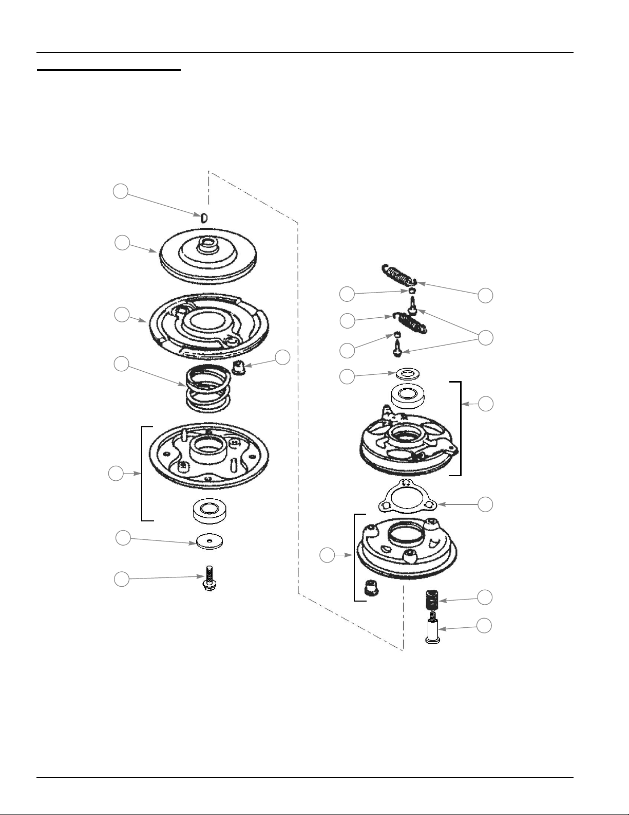
Mower Deck Assembly . . . . . . . . . . . . . . . . . . . . . . . . . . . . . . . . . . . 6-4
Wheel Breakdown . . . . . . . . . . . . . . . . . . . . . . . . . . . . . . . . . . . . . . . 6-6
Brake Assembly. . . . . . . . . . . . . . . . . . . . . . . . . . . . . . . . . . . . . . . . . 6-8
Cover Unit . . . . . . . . . . . . . . . . . . . . . . . . . . . . . . . . . . . . . . . . . . . . 6-10
Gear Case—71008-431. . . . . . . . . . . . . . . . . . . . . . . . . . . . . . . . . . 6-12
Mulch Kit . . . . . . . . . . . . . . . . . . . . . . . . . . . . . . . . . . . . . . . . . . . . . 6-14
Handle, Levers & Catcher System. . . . . . . . . . . . . . . . . . . . . . . . . . 6-16
Decals . . . . . . . . . . . . . . . . . . . . . . . . . . . . . . . . . . . . . . . . . . . . . . . 6-18
108548_0711 6-1
Page 32

6-2 108548_0711
Page 33

General Information
This Manual covers the Hustler M-1 model 929208.
Service Literature
PART NO. DESCRIPTION
108548 OWNER’S MANUAL
601825 HONDA GXV160 ENGINE MANUAL
Note: When ordering parts, you must use the part number as shown for each part, not the index number. Always give
the model and serial number to your parts and service representative.
Using this manual
Illustrations used were current at the time of printing, but subsequent production changes may cause your machine to
vary slightly in detail. Excel Industries, Inc. reserves the right to redesign and change the machine as deemed necessary, without notification. If a change has been made to your machine which is not reflected in this parts manual, see
your Hustler dealer for current information and parts.
Standard Torques
The following chart lists the standard torque values for the threaded fasteners found in this manual. Torque all cap
screws, nuts and set screws to these values unless a different torque is shown in the Notes section next to the fastener.
SIZE FT-LBS N-M SIZE FT-LBS N-M
.250 8.2 11.1 M3 1 1.3
.312 17 23 M4 2.2 3
.375 30 40 M5 4.5 6.1
.438 48 65 M6 7.7 10.4
.500 73 99 M8 18.5 25
.562 105 143 M10 37 50
.625 145 200 M12 64 87
.750 260 350 M14 80 108.5
.875 420 565 M16 160 215
1.00 625 850 M20 320 435
M24 555 750
108548_0711 6-3
Page 34

Mower Deck Assembly
See “Cover Unit” on
page 6-10.
15
19
16
17
18
7
40
45
35
38
37
37
37
5
5
36
7
41
4
3
1
6
24
7
23
7
10
41
3
4
9
25
13
11
7
39
37
7
34
36
4
28
27
7
14
7
40
43
29
26
7
30
8
31
32
12
42
43
44
21
22
20
7
2
6-4 108548_0711
4
33
Page 35

Mower Deck Assy
ITEM
NO.
1 51043-151-107 1 HOUSING MOWER DECK
2 36068-204 1 GUARD
3 51090-117-09 2 PROTECTOR
4 342L-0616 5 FLANGE BOLT
5 512L-0600 4 HEX NUT
6 36065-180 1 COVER
7 342L-0612 12 FLANGE TAPPING BOLT
8 11006-155 1 STAY C.P.
9 11113-407 1 STAY
10 11113-292 1 STAY
11 36068-196-49 1 GUARD REAR DOOR
12 36080-149 1 RUBBER SHEET
13 64014-324 1 SHAFT
14 68013-336 1 SPRING
15 71082-111 1 FAN ASSY (INCLUDES ITEMS 16–19)
16 51125-103 1 FAN
17 11102-151 1 HOLDER
18 31062-169 4 PRE-COAT LOCK BOLT
19 579L-0600 4 FLANGE BOLT
20 61024-208 1 SPACER
21 91014-189 1 BLADE STD M-1
22 31057-197 2 HEX BOLT
23 31057-243 4 HEX BOLT
24 61024-142 3 SPACER
25 71067-106 1 BRAKE ASSY
26 91097-101 1 UNIVERSAL JOINT
27 812V-2000 1 C-SNAP RING FOR SHAFT
28 717B-0418 1 PARALLEL PIN
29 64014-339 1 SHAFT
30 91049-129 1 CONNECTOR
31 68036-280 2 WASHER
32 816V-0800 1 E-SNAP RING
33 36065-438 1 COVER
34 51116-149 1 LEFT HANDLE BRACKET
35 51116-167 1 RIGHT HANDLE BRACKET
36 31057-255 4 HEX BOLT
37 512L-0800 4 HEX NUT
38 11113-429 1 RS STAY
39 11113-428 1 LS STAY
40 31057-181 2 HEX BOLT
41 11113-415 2 STAY
42 71008-431 1 GEAR CASE ASSY
43 711V-0522 2 SPRING PIN
44 733L-1000 1 SNAP PIN
45 94401-16150 1 WOODRUFF KEY
SERVICE
PART NO.
QTY. DESCRIPTION
NOTES:
108548_0711 6-5
Page 36

Wheel Breakdown
1
33
37
22
44
12
46
17
5
45
47
9
6
41
13
30
39
32
12
11
31
21
42
40
10
7
46
4
33
20
35
8
41
22
42
19
49
27
28
30
25
26
29
15
31
26
25
32
4
1
24
3
23
12
11
13
12
9
17
14
5
16
6
8
7
4
2
18
29
30
15
48
22
30
38
41
46
36
4
34
17
16
43
21
45
37
47
20
17
22
6-6 108548_0711
Page 37

Wheel Breakdown
ITEM
NO.
1 71041-144 2 WHEEL ASSEMBLY (INCLUDES ITEMS 2–4)
2 N/A 2 TIRE—(NOT SERVICED SEPARATELY)
3 N/A 2 WHEEL—(NOT SERVICED SEPARATELY)
4 916B-6002 8 BEARING
5 11086-119 2 STOPPER
6 61003-112 2 THRUST PLATE
7 31034-137 2 PIN
8 68036-270 2 WASHER
9 68036-146 2 WASHER
10 71158-104 1 RATCHET ASSEMBLY RIGHT (INCLUDES ITEMS 11–13)
11 N/A 2 HOLDER—(NOT SERVICED SEPARATELY)
12 N/A 4 PIN—(NOT SERVICED SEPARATELY)
13 N/A 2 SPRING—(NOT SERVICED SEPARATELY)
14 71158-103 1 RATCHET ASSEMBLY LEFT (INCLUDES ITEMS 11–13)
15 68036-275 2 WASHER
16 31057-181 4 HEXAGON BOLT
17 68036-101 6 WASHER
18 11006-151 1 STAY C.P. REAR LEFT
19 11006-152 1 STAY C.P. REAR RIGHT
20 342L-0612 2 SELF-TAPPING FLANGE BOLT
21 31057-255 2 HEXAGON BOLT
22 584L-0800 4 U-FLANGE NUT
23 71122-110 1 LEFT ADJUSTER ASSY (INCLUDES ITEMS 24–26)
24 11142-125 1 ADJUSTER REAR LEFT
25 11102-228 2 HOLDER
26 916B-6202 2 BEARING
27 71122-111 1 RIGHT ADJUSTER ASSY (INCLUDES ITEMS 25, 26 AND 28)
28 11142-126 1 ADJUSTER REAR RIGHT
29 11150-105-09 1 ADJUST LEVER
30 36061-121 4 KNOB
31 613L-0800 2 WASHER
32 569L-0800 2 FLANGE NYLON NUT
33 71041-135 2 WHEEL ASSEMBLY (A.W.) (INCLUDES ITEMS 4, 34 AND 35)
34 N/A 2 TIRE—(NOT SERVICED SEPARATELY)
35 N/A 2 WHEEL—(NOT SERVICED SEPARATELY)
36 11083-332 2 COLLAR
37 51113-119 2 RING
38 11006-153 1 STAY C.P. FRONT LEFT
39 11006-154 1 STAY C.P. FRONT RIGHT
40 11153-114-102 1 BUMPER FRONT
41 335L-0625 6 FLANGE BOLT
42 569L-0600 6 FLANGE NYLON NUT
43 11142-129 1 ADJUSTER FRONT LEFT
44 11142-130 1 ADJUSTER FRONT RIGHT
45 11150-109-09 2 ADJUST LEVER
46 68013-393 4 SPRING
47 68007-105 A/R SHIM
48 11113-418 1 STAY LEFT
49 11113-417 1 STAY RIGHT
SERVICE
PART NO.
QTY. DESCRIPTION
NOTES:
108548_0711 6-7
Page 38
Brake Assembly
17
13
3
16
15
11
18
2
8
4
2
12
6
8
9
5
7
14
10
6-8 108548_0711
Page 39

Brake Assembly
ITEM
NO.
1 71067-106 1 BRAKE ASSEMBLY
2 19512-883-000 2 FAN COLLAR
3 72600-va4-010 1 HOLDER ASSEMBLY
4 72613-va4-000 2 BLADE HOLDER BUSHING
5 75090-va4-030 1 CONTROL ASSEMBLY
6 75100-va4-010 1 BRAKE C.P.
7 75110-VA4-000 1 BALL RETAINER C.P.
8 75182-VA3-j00 2 CLUTCH RETURN SPRING
9 90014-952-000 2 FLANGE BOLT
10 90021-VA4-000 3 SPECIAL BOLT
11 90409-952-000 1 WASHER
12 90501-952-010 1 THRUST WASHER
13 75130-VA4-000 1 BRAKE DISK
14 75132-VA4-000 3 BRAKE HOLDER SPRING
15 75183-VA3-j00 1 CLUTCH SPRING
16 75150-VA3-j01 1 DRIVEN DISK C.P.
17 94401-16150 1 WOODRUFF KEY
18 90105-960-003 1 BOLT 10 X 25
SERVICE PART
NO.
QTY. DESCRIPTION
NOTES:
108548_0711 6-9
Page 40

Cover Unit
2
8
10
5
4
3
1
7
6
9
13
11
12
15
14
8
16
6-10 108548_0711
Page 41

Cover Unit
ITEM
NO.
1 11006-166 1 STAY C.P.
2 36080-154 1 RUBBER SHEET
3 11113-420 1 STAY
4 613L-0800 1 PLAIN WASHER
5 423U-0812 1 SOCKET SCREW FLANGE
6 64014-373 1 SHAFT
7 11083-387 1 COLLAR
8 31057-181 2 HEXAGON BOLT
9 64014-374 1 SHAFT
10 51079-124 1 COVER C.P.
11 36080-153 1 RUBBER SHEET
12 11050-182 1 FIXING PLATE
13 569L-0400 3 FLANGE NYLON NUT
14 11006-167 1 STAY C.P.
15 36080-155 1 RUBBER SHEET
16 342L-0612 1 FLANGE TAPPING BOLT
SERVICE
PART NO.
QTY. DESCRIPTION
NOTES:
108548_0711 6-11
Page 42

Gear Case—71008-431
15
14
13
16
37
21
20
19
17
18
31
32
10
25
26
27
28
29
30
2
6
42
30
9
4
39
40
5
3
38
33
11
1
35
45
12
22
23
24
36
34
7
8
43
4
5
41
44
6-12 108548_0711
Page 43

Gear Case—71008-431
ITEM
NO.
1 51001-195 1 GEAR CASE
2 51001-196 1 GEAR CASE
3 61002-161 1 OIL SEAL
4 61002-162 2 OIL SEAL
5 61002-163 2 OIL SEAL
6 64024-104 1 SHIFTER SHAFT
7 11104-119 1 ARM
8 320L-0525 1 HEXAGON BOLT
9 611L-0500 1 PLAIN WASHER
10 571L-0500 1 FLANGE NUT
11 61003-109 1 THRUST PLATE
12 71902-194 1 PINION
13 91097-101 1 UNIVERSAL JOINT
14 812V-2000 1 C-SNAP RING
15 717B-0418 1 PARALLEL PIN
16 11097-106 1 SHIFTER FORK
17 11104-137 1 ARM
18 419U-0630 1 SOCKET SCREW
19 611L-0600 1 PLAIN WASHER
20 661L-0600 1 SPRING LOCK WASHER
21 512L-0600 1 HEXAGON NUT
22 61024-117 1 SPACER
23 78001-162 1 BEVEL GEAR
24 11129-107 1 CLUTCH
25 64014-236 1 SHAFT
26 68013-262 1 SPRING
27 31034-199 1 PIN
28 736U-0320 1 SPRING PIN
29 64014-235 1 SHAFT
30 61024-118 2 SPACER
31 78004-156 1 GEAR
32 78004-155 1 GEAR
33 64014-344 1 SHAFT
34 78012-107 1 GEAR C.P.
35 31034-150 1 PIN
36 812V-2200 1 C-SNAP RING
37 214B-11000 1 O-RING
38 11083-201 2 COLLAR
39 31057-262 1 HEXAGON BOLT
40 68001-110 1 FIBER WASHER
41 11006-191 1 STAY C.P.
42 315L-0625 3 HEXAGON BOLT
43 315L-0635 2 HEXAGON BOLT
44 318L-0612 1 HEXAGON BOLT
45 68007-132 A/R SHIM
SERVICE
PART NO.
QTY. DESCRIPTION
NOTES:
108548_0711 6-13
Page 44

Mulch Kit
61
3 7 8
4
10
12
6-14 108548_0711
Page 45

Mulch Kit
ITEM
NO.
1 31044-134 1 PLUG
2 71906-460 1 MULCH BLADE SET (NOT SHOWN; INCLUDES ITEMS 3 & 4)
3 N/A 1 BLADE—(NOT SERVICED SEPARATELY)
4 N/A 1 BLADE—(NOT SERVICED SEPARATELY)
5 71906-459 1 MULCH SPACER KIT (INCLUDES ITEMS 6–12)
6 61024-220 1 SPACER
7 11024-150 1 STAND
8 11086-198 1 STOPPER
9 71137-276 1 BOLT NUT SET (NOT SHOWN; INCLUDES ITEM 10)
10 335L-0610 1 M6 X 10 X 1.0 FLANGE BOLT
11 71137-247 1 BOLT NUT SET (NOT SHOWN; INCLUDES ITEM 12)
12 31057-220 2 M10 X 30 X 1.25 FLANGE BOLT
SERVICE
PART NO.
QTY. DESCRIPTION
NOTES:
108548_0711 6-15
Page 46

Handle, Levers & Catcher System
50
38
49
43
40
42
41
33
43
42
40
40
2
39
1
32
31
40
29
35
45
22
28
36
20
7
18
34
5
53
4
30
12
6
14
13
21
3
11
15
10
8
9
18
17
16
23
24
25
26
27
52
38
41
46
44
6-16 108548_0711
52
47
48
51
Page 47

Handle, Levers & Catcher System
ITEM
NO.
1 51027-268- 1 HANDLE LOWER
2 51027-280- 1 HANDLE UPPER
3 11095-172 1 LEVER
4 36110-102 1 BUTTON
5 11049-109 1 SLIDE PLATE
6 64014-336 1 SHAFT
7 376L-0612 1 TRUSS SCREW
8 71203-135 1 ARM C.P.
9 76007-183 1 BUSHING
10 68013-371 1 SPRING
11 31056-127 1 GIB-HEADED PIN
12 576V-0600 1 PUSH NUT
13 68013-392 1 SPRING
14 11109-111 1 LINK
15 61023-190 1 SLEEVE
16 64014-337 1 SHAFT
17 812V-0800 1 C-SNAP RING
18 613L-0800 2 WASHER
19 71161-120-09 1 LEVER ASSEMBLY
20 N/A 1 LEVER (INCLUDES ITEMS 21 & 22)
21 76007-131 1 BUSHING
22 76007-191 1 BUSHING
23 68013-391 1 SPRING
24 91010-169 1 THROTTLE LEVER
25 61003-113 1 THRUST PLATE
26 68013-356 1 SPRING
27 31058-168 1 HEX NUT
28 11095-117 1 LEVER
29 31062-109 1 PRE-COAT LOCK BOLT
30 31057-281 1 HEX BOLT
31 68036-125 1 WASHER
32 563L-0600 1 U-HEX CAP NUT
33 71285-109 1 HOLDER C.P.
34 68013-161 1 SPRING
35 71900-796 1 COVER ASSEMBLY
36 470L-0514 2 TAPPING SCREW
37 71900-845 1 BOLT SET
38 569L-0800 4 FLANGE NYLON NUT
39 31057-256 2 HEX BOLT
40 583L-0800 6 FLANGE CAP NUT
41 71900-846 1 BAR SET
42 11012-132 2 HANGER BAND
43 31057-181 2 HEX BOLT
44 68028-118 3 WIRE BAND
45 91003-125 1 CONTROL CABLE SPD
46 91003-180 1 CONTROL CABLE DRV
47 91001-329 1 THROTTLE WIRE
48 91003-169 1 CONTROL CABLE BBC
49 11062-178 1 FRAME C.P.
50 36098-155 1 GRASS BAG C.P.
51 41003-201 1 TUBE
52 68028-119 2 WIRE BAND
53 36080-156 1 RUBBER SHEET
SERVICE
PART NO.
QTY. DESCRIPTION
NOTES:
108548_0711 6-17
Page 48

Decals
1
LEFT SIDE
4
2
3
3
RIGHT SIDE
FRONT
6-18 108548_0711
Page 49

Decals
ITEM
NO.
1 601956 1 M-1 SAFE OPERATION DECAL
2 601949 1 M-1 DANGER DECAL
3 601957 2 M-1 DECK WARNING DECAL
4 601955 1 M-1 HUSTLER LOGO DECAL
SERVICE
PART NO.
QTY. DESCRIPTION
NOTES:
1. 602887 (DECAL SET, KAAZ DECK) includes item numbers 1–4.
2.
108548_0711 6-19
Page 50

6-20 108548_0711
Page 51

INDEX
PAGE PAGE
108548 . . . . . . . . . . . . . . . . . . . . . . . . . . . . . . . . . . . 6-3
11006-151 . . . . . . . . . . . . . . . . . . . . . . . . . . . . . . . . 6-7
11006-152 . . . . . . . . . . . . . . . . . . . . . . . . . . . . . . . . 6-7
11006-153 . . . . . . . . . . . . . . . . . . . . . . . . . . . . . . . . 6-7
11006-154 . . . . . . . . . . . . . . . . . . . . . . . . . . . . . . . . 6-7
11006-155 . . . . . . . . . . . . . . . . . . . . . . . . . . . . . . . . 6-5
11006-157 . . . . . . . . . . . . . . . . . . . . . . . . . . . . . . . 6-13
11006-166 . . . . . . . . . . . . . . . . . . . . . . . . . . . . . . . 6-11
11006-167 . . . . . . . . . . . . . . . . . . . . . . . . . . . . . . . 6-11
11012-132 . . . . . . . . . . . . . . . . . . . . . . . . . . . . . . . 6-17
11024-150 . . . . . . . . . . . . . . . . . . . . . . . . . . . . . . . 6-15
11049-109 . . . . . . . . . . . . . . . . . . . . . . . . . . . . . . . 6-17
11050-182 . . . . . . . . . . . . . . . . . . . . . . . . . . . . . . . 6-11
11062-178 . . . . . . . . . . . . . . . . . . . . . . . . . . . . . . . 6-17
11083-201 . . . . . . . . . . . . . . . . . . . . . . . . . . . . . . . 6-13
11083-332 . . . . . . . . . . . . . . . . . . . . . . . . . . . . . . . . 6-7
11083-387 . . . . . . . . . . . . . . . . . . . . . . . . . . . . . . . 6-11
11142-130 . . . . . . . . . . . . . . . . . . . . . . . . . . . . . . . . 6-7
11150-105 . . . . . . . . . . . . . . . . . . . . . . . . . . . . . . . . 6-7
11150-109-09 . . . . . . . . . . . . . . . . . . . . . . . . . . . . . 6-7
11153-114-102 . . . . . . . . . . . . . . . . . . . . . . . . . . . . 6-7
19512-883-000 . . . . . . . . . . . . . . . . . . . . . . . . . . . . 6-9
214B-11000 . . . . . . . . . . . . . . . . . . . . . . . . . . . . . . 6-13
31034-137 . . . . . . . . . . . . . . . . . . . . . . . . . . . . . . . . 6-7
31034-150 . . . . . . . . . . . . . . . . . . . . . . . . . . . . . . . 6-13
31034-171 . . . . . . . . . . . . . . . . . . . . . . . . . . . . . . . 6-13
31044-134 . . . . . . . . . . . . . . . . . . . . . . . . . . . . . . . 6-15
31056-127 . . . . . . . . . . . . . . . . . . . . . . . . . . . . . . . 6-17
31057-181 . . . . . . . . . . . . . . . . . . . 6-5, 6-7, 6-11, 6-17
31057-197 . . . . . . . . . . . . . . . . . . . . . . . . . . . . . . . . 6-5
31057-220 . . . . . . . . . . . . . . . . . . . . . . . . . . . . . . . 6-15
31057-243 . . . . . . . . . . . . . . . . . . . . . . . . . . . . . . . . 6-5
31057-255 . . . . . . . . . . . . . . . . . . . . . . . . . . . . .6-5, 6-7
31057-256 . . . . . . . . . . . . . . . . . . . . . . . . . . . . . . . 6-17
11086-119 . . . . . . . . . . . . . . . . . . . . . . . . . . . . . . . . 6-7
11086-198 . . . . . . . . . . . . . . . . . . . . . . . . . . . . . . . 6-15
11095-117 . . . . . . . . . . . . . . . . . . . . . . . . . . . . . . . 6-17
11095-172 . . . . . . . . . . . . . . . . . . . . . . . . . . . . . . . 6-17
11097-106 . . . . . . . . . . . . . . . . . . . . . . . . . . . . . . . 6-13
11102-126 . . . . . . . . . . . . . . . . . . . . . . . . . . . . . . . . 6-7
11102-151 . . . . . . . . . . . . . . . . . . . . . . . . . . . . . . . . 6-5
11102-228 . . . . . . . . . . . . . . . . . . . . . . . . . . . . . . . . 6-7
11104-119 . . . . . . . . . . . . . . . . . . . . . . . . . . . . . . . 6-13
11104-137 . . . . . . . . . . . . . . . . . . . . . . . . . . . . . . . 6-13
11109-111 . . . . . . . . . . . . . . . . . . . . . . . . . . . . . . . 6-17
11113-292 . . . . . . . . . . . . . . . . . . . . . . . . . . . . . . . . 6-5
11113-407 . . . . . . . . . . . . . . . . . . . . . . . . . . . . . . . . 6-5
11113-408 . . . . . . . . . . . . . . . . . . . . . . . . . . . . . . . . 6-5
11113-415 . . . . . . . . . . . . . . . . . . . . . . . . . . . . . . . . 6-5
11113-417 . . . . . . . . . . . . . . . . . . . . . . . . . . . . . . . . 6-7
11113-418 . . . . . . . . . . . . . . . . . . . . . . . . . . . . . . . . 6-7
31057-262 . . . . . . . . . . . . . . . . . . . . . . . . . . . . . . . 6-13
31057-281 . . . . . . . . . . . . . . . . . . . . . . . . . . . . . . . 6-17
31058-168 . . . . . . . . . . . . . . . . . . . . . . . . . . . . . . . 6-17
31062-109 . . . . . . . . . . . . . . . . . . . . . . . . . . . . . . . 6-17
31062-169 . . . . . . . . . . . . . . . . . . . . . . . . . . . . . . . . 6-5
315L-0625 . . . . . . . . . . . . . . . . . . . . . . . . . . . . . . . 6-13
315L-0635 . . . . . . . . . . . . . . . . . . . . . . . . . . . . . . . 6-13
318L-0612 . . . . . . . . . . . . . . . . . . . . . . . . . . . . . . . 6-13
320L-0525 . . . . . . . . . . . . . . . . . . . . . . . . . . . . . . . 6-13
335L-0610 . . . . . . . . . . . . . . . . . . . . . . . . . . . . . . . 6-15
335l-0625 . . . . . . . . . . . . . . . . . . . . . . . . . . . . . . . . 6-7
342L-0612 . . . . . . . . . . . . . . . . . . . . . . . . 6-5, 6-7, 6-11
342L-0616 . . . . . . . . . . . . . . . . . . . . . . . . . . . . . . . . 6-5
36061-121 . . . . . . . . . . . . . . . . . . . . . . . . . . . . . . . . 6-7
36065-180 . . . . . . . . . . . . . . . . . . . . . . . . . . . . . . . . 6-5
36065-438 . . . . . . . . . . . . . . . . . . . . . . . . . . . . . . . . 6-5
36068-196-49 . . . . . . . . . . . . . . . . . . . . . . . . . . . . . 6-5
11113-420 . . . . . . . . . . . . . . . . . . . . . . . . . . . . . . . 6-11
11129-107 . . . . . . . . . . . . . . . . . . . . . . . . . . . . . . . 6-13
11142-125 . . . . . . . . . . . . . . . . . . . . . . . . . . . . . . . . 6-7
11142-129 . . . . . . . . . . . . . . . . . . . . . . . . . . . . . . . . 6-7
108548_0711 i-1
36068-204 . . . . . . . . . . . . . . . . . . . . . . . . . . . . . . . . 6-5
36080-149 . . . . . . . . . . . . . . . . . . . . . . . . . . . . . . . . 6-5
36080-153 . . . . . . . . . . . . . . . . . . . . . . . . . . . . . . . 6-11
36080-154 . . . . . . . . . . . . . . . . . . . . . . . . . . . . . . . 6-11
Page 52

INDEX
PAGE PAGE
36080-155 . . . . . . . . . . . . . . . . . . . . . . . . . . . . . . . 6-11
36080-156 . . . . . . . . . . . . . . . . . . . . . . . . . . . . . . . 6-17
36098-155 . . . . . . . . . . . . . . . . . . . . . . . . . . . . . . . 6-17
36110-102 . . . . . . . . . . . . . . . . . . . . . . . . . . . . . . . 6-17
376L-0612 . . . . . . . . . . . . . . . . . . . . . . . . . . . . . . . 6-17
41003-201 . . . . . . . . . . . . . . . . . . . . . . . . . . . . . . . 6-17
419U-0630 . . . . . . . . . . . . . . . . . . . . . . . . . . . . . . . 6-13
423U-0812 . . . . . . . . . . . . . . . . . . . . . . . . . . . . . . . 6-11
470L-0514 . . . . . . . . . . . . . . . . . . . . . . . . . . . . . . . 6-17
51001-195 . . . . . . . . . . . . . . . . . . . . . . . . . . . . . . . 6-13
51001-196 . . . . . . . . . . . . . . . . . . . . . . . . . . . . . . . 6-13
51027-268-103 . . . . . . . . . . . . . . . . . . . . . . . . . . . 6-17
51027-280-103 . . . . . . . . . . . . . . . . . . . . . . . . . . . 6-17
51043-151-107 . . . . . . . . . . . . . . . . . . . . . . . . . . . . 6-5
51079-124 . . . . . . . . . . . . . . . . . . . . . . . . . . . . . . . 6-11
51090-117-09 . . . . . . . . . . . . . . . . . . . . . . . . . . . . . 6-5
51113-119 . . . . . . . . . . . . . . . . . . . . . . . . . . . . . . . . 6-7
61002-162 . . . . . . . . . . . . . . . . . . . . . . . . . . . . . . . .6-13
61002-163 . . . . . . . . . . . . . . . . . . . . . . . . . . . . . . . .6-13
61003-109 . . . . . . . . . . . . . . . . . . . . . . . . . . . . . . . .6-13
61003-112 . . . . . . . . . . . . . . . . . . . . . . . . . . . . . . . . .6-7
61003-113 . . . . . . . . . . . . . . . . . . . . . . . . . . . . . . . .6-17
61023-190 . . . . . . . . . . . . . . . . . . . . . . . . . . . . . . . .6-17
61024-117 . . . . . . . . . . . . . . . . . . . . . . . . . . . . . . . .6-13
61024-118 . . . . . . . . . . . . . . . . . . . . . . . . . . . . . . . .6-13
61024-142 . . . . . . . . . . . . . . . . . . . . . . . . . . . . . . . . .6-5
61024-208 . . . . . . . . . . . . . . . . . . . . . . . . . . . . . . . . .6-5
61024-220 . . . . . . . . . . . . . . . . . . . . . . . . . . . . . . . .6-15
611L-0500 . . . . . . . . . . . . . . . . . . . . . . . . . . . . . . . .6-13
611L-0600 . . . . . . . . . . . . . . . . . . . . . . . . . . . . . . . .6-13
613L-0800 . . . . . . . . . . . . . . . . . . . . . . . . . . . 6-11, 6-17
613l-0800 . . . . . . . . . . . . . . . . . . . . . . . . . . . . . . . . .6-7
64014-235 . . . . . . . . . . . . . . . . . . . . . . . . . . . . . . . .6-13
64014-236 . . . . . . . . . . . . . . . . . . . . . . . . . . . . . . . .6-13
51116-149 . . . . . . . . . . . . . . . . . . . . . . . . . . . . . . . . 6-5
51116-167 . . . . . . . . . . . . . . . . . . . . . . . . . . . . . . . . 6-5
51125-103 . . . . . . . . . . . . . . . . . . . . . . . . . . . . . . . . 6-5
512L-0600 . . . . . . . . . . . . . . . . . . . . . . . . . . . .6-5, 6-13
512L-0800 . . . . . . . . . . . . . . . . . . . . . . . . . . . . . . . . 6-5
563L-0600 . . . . . . . . . . . . . . . . . . . . . . . . . . . . . . . 6-17
569L-0400 . . . . . . . . . . . . . . . . . . . . . . . . . . . . . . . 6-11
569l-0600 . . . . . . . . . . . . . . . . . . . . . . . . . . . . . . . . 6-7
569L-0800 . . . . . . . . . . . . . . . . . . . . . . . . . . . . . . . 6-17
569l-0800 . . . . . . . . . . . . . . . . . . . . . . . . . . . . . . . . 6-7
571L-0500 . . . . . . . . . . . . . . . . . . . . . . . . . . . . . . . 6-13
576V-0600 . . . . . . . . . . . . . . . . . . . . . . . . . . . . . . . 6-17
579L-0600 . . . . . . . . . . . . . . . . . . . . . . . . . . . . . . . . 6-5
583L-0800 . . . . . . . . . . . . . . . . . . . . . . . . . . . . . . . 6-17
584L-0800 . . . . . . . . . . . . . . . . . . . . . . . . . . . . . . . . 6-7
601825 . . . . . . . . . . . . . . . . . . . . . . . . . . . . . . . . . . 6-3
601949 . . . . . . . . . . . . . . . . . . . . . . . . . . . . . . . . . 6-19
64014-324 . . . . . . . . . . . . . . . . . . . . . . . . . . . . . . . . .6-5
64014-336 . . . . . . . . . . . . . . . . . . . . . . . . . . . . . . . .6-17
64014-337 . . . . . . . . . . . . . . . . . . . . . . . . . . . . . . . .6-17
64014-339 . . . . . . . . . . . . . . . . . . . . . . . . . . . . . . . . .6-5
64014-344 . . . . . . . . . . . . . . . . . . . . . . . . . . . . . . . .6-13
64014-373 . . . . . . . . . . . . . . . . . . . . . . . . . . . . . . . .6-11
64014-374 . . . . . . . . . . . . . . . . . . . . . . . . . . . . . . . .6-11
64024-104 . . . . . . . . . . . . . . . . . . . . . . . . . . . . . . . .6-13
661L-0600 . . . . . . . . . . . . . . . . . . . . . . . . . . . . . . . .6-13
68001-110 . . . . . . . . . . . . . . . . . . . . . . . . . . . . . . . .6-13
68007-105 . . . . . . . . . . . . . . . . . . . . . . . . . . . . . . . . .6-7
68007-132 . . . . . . . . . . . . . . . . . . . . . . . . . . . . . . . .6-13
68013-161 . . . . . . . . . . . . . . . . . . . . . . . . . . . . . . . .6-17
68013-262 . . . . . . . . . . . . . . . . . . . . . . . . . . . . . . . .6-13
68013-336 . . . . . . . . . . . . . . . . . . . . . . . . . . . . . . . . .6-5
68013-356 . . . . . . . . . . . . . . . . . . . . . . . . . . . . . . . .6-17
68013-371 . . . . . . . . . . . . . . . . . . . . . . . . . . . . . . . .6-17
601955 . . . . . . . . . . . . . . . . . . . . . . . . . . . . . . . . . 6-19
601956 . . . . . . . . . . . . . . . . . . . . . . . . . . . . . . . . . 6-19
601957 . . . . . . . . . . . . . . . . . . . . . . . . . . . . . . . . . 6-19
61002-161 . . . . . . . . . . . . . . . . . . . . . . . . . . . . . . . 6-13
68013-391 . . . . . . . . . . . . . . . . . . . . . . . . . . . . . . . .6-17
68013-392 . . . . . . . . . . . . . . . . . . . . . . . . . . . . . . . .6-17
68013-393 . . . . . . . . . . . . . . . . . . . . . . . . . . . . . . . . .6-7
68028-118 . . . . . . . . . . . . . . . . . . . . . . . . . . . . . . . .6-17
i-2 108548_0711
Page 53

INDEX
PAGE PAGE
68028-119 . . . . . . . . . . . . . . . . . . . . . . . . . . . . . . . 6-17
68036-101 . . . . . . . . . . . . . . . . . . . . . . . . . . . . . . . . 6-7
68036-125 . . . . . . . . . . . . . . . . . . . . . . . . . . . . . . . 6-17
68036-146 . . . . . . . . . . . . . . . . . . . . . . . . . . . . . . . . 6-7
68036-270 . . . . . . . . . . . . . . . . . . . . . . . . . . . . . . . . 6-7
68036-275 . . . . . . . . . . . . . . . . . . . . . . . . . . . . . . . . 6-7
68036-280 . . . . . . . . . . . . . . . . . . . . . . . . . . . . . . . . 6-5
71008-377 . . . . . . . . . . . . . . . . . . . . . . . . . . . . . . . . 6-5
71041-135 . . . . . . . . . . . . . . . . . . . . . . . . . . . . . . . . 6-7
71041-144 . . . . . . . . . . . . . . . . . . . . . . . . . . . . . . . . 6-7
71067-106 . . . . . . . . . . . . . . . . . . . . . . . . . . . . 6-5, 6-9
71082-111 . . . . . . . . . . . . . . . . . . . . . . . . . . . . . . . . 6-5
71122-110 . . . . . . . . . . . . . . . . . . . . . . . . . . . . . . . . 6-7
71122-111 . . . . . . . . . . . . . . . . . . . . . . . . . . . . . . . . 6-7
71137-247 . . . . . . . . . . . . . . . . . . . . . . . . . . . . . . . 6-15
71137-276 . . . . . . . . . . . . . . . . . . . . . . . . . . . . . . . 6-15
71158-103 . . . . . . . . . . . . . . . . . . . . . . . . . . . . . . . . 6-7
75182-VA3-j00 . . . . . . . . . . . . . . . . . . . . . . . . . . . . 6-9
75183-VA3-j00 . . . . . . . . . . . . . . . . . . . . . . . . . . . . 6-9
76007-131 . . . . . . . . . . . . . . . . . . . . . . . . . . . . . . . 6-17
76007-183 . . . . . . . . . . . . . . . . . . . . . . . . . . . . . . . 6-17
76007-191 . . . . . . . . . . . . . . . . . . . . . . . . . . . . . . . 6-17
78001-162 . . . . . . . . . . . . . . . . . . . . . . . . . . . . . . . 6-13
78003-130 . . . . . . . . . . . . . . . . . . . . . . . . . . . . . . . 6-13
78004-155 . . . . . . . . . . . . . . . . . . . . . . . . . . . . . . . 6-13
78004-156 . . . . . . . . . . . . . . . . . . . . . . . . . . . . . . . 6-13
78012-107 . . . . . . . . . . . . . . . . . . . . . . . . . . . . . . . 6-13
812V-0800 . . . . . . . . . . . . . . . . . . . . . . . . . . . . . . . 6-17
812V-2000 . . . . . . . . . . . . . . . . . . . . . . . . . . . .6-5, 6-13
812V-2200 . . . . . . . . . . . . . . . . . . . . . . . . . . . . . . . 6-13
816V-0800 . . . . . . . . . . . . . . . . . . . . . . . . . . . . . . . . 6-5
90014-952-000 . . . . . . . . . . . . . . . . . . . . . . . . . . . . 6-9
90021-VA4-000 . . . . . . . . . . . . . . . . . . . . . . . . . . . . 6-9
90105-960-003 . . . . . . . . . . . . . . . . . . . . . . . . . . . . 6-9
71158-104 . . . . . . . . . . . . . . . . . . . . . . . . . . . . . . . . 6-7
71161-120-09 . . . . . . . . . . . . . . . . . . . . . . . . . . . . . 6-17
711V-0522 . . . . . . . . . . . . . . . . . . . . . . . . . . . . . . . . 6-5
71203-135 . . . . . . . . . . . . . . . . . . . . . . . . . . . . . . . 6-17
71285-109 . . . . . . . . . . . . . . . . . . . . . . . . . . . . . . . 6-17
717B-0418 . . . . . . . . . . . . . . . . . . . . . . . . . . . 6-5, 6-13
71900-796 . . . . . . . . . . . . . . . . . . . . . . . . . . . . . . . 6-17
71900-845 . . . . . . . . . . . . . . . . . . . . . . . . . . . . . . . 6-17
71900-846 . . . . . . . . . . . . . . . . . . . . . . . . . . . . . . . 6-17
71906-459 . . . . . . . . . . . . . . . . . . . . . . . . . . . . . . . 6-15
71906-460 . . . . . . . . . . . . . . . . . . . . . . . . . . . . . . . 6-15
72600-VA4-010 . . . . . . . . . . . . . . . . . . . . . . . . . . . . 6-9
72613-VA4-000 . . . . . . . . . . . . . . . . . . . . . . . . . . . . 6-9
733L-1000 . . . . . . . . . . . . . . . . . . . . . . . . . . . . . . . . 6-5
736U-0320 . . . . . . . . . . . . . . . . . . . . . . . . . . . . . . . 6-13
75090-VA4-030 . . . . . . . . . . . . . . . . . . . . . . . . . . . . 6-9
75100-VA4-010 . . . . . . . . . . . . . . . . . . . . . . . . . . . . 6-9
90409-952-000 . . . . . . . . . . . . . . . . . . . . . . . . . . . . 6-9
90501-952-010 . . . . . . . . . . . . . . . . . . . . . . . . . . . . 6-9
91001-329 . . . . . . . . . . . . . . . . . . . . . . . . . . . . . . . 6-17
91003-125 . . . . . . . . . . . . . . . . . . . . . . . . . . . . . . . 6-17
91003-169 . . . . . . . . . . . . . . . . . . . . . . . . . . . . . . . 6-17
91003-180 . . . . . . . . . . . . . . . . . . . . . . . . . . . . . . . 6-17
91010-169 . . . . . . . . . . . . . . . . . . . . . . . . . . . . . . . 6-17
91014-189 . . . . . . . . . . . . . . . . . . . . . . . . . . . . . . . . 6-5
91049-129 . . . . . . . . . . . . . . . . . . . . . . . . . . . . . . . . 6-5
91097-101 . . . . . . . . . . . . . . . . . . . . . . . . . . . .6-5, 6-13
916B-6002 . . . . . . . . . . . . . . . . . . . . . . . . . . . . . . . . 6-7
916B-6202 . . . . . . . . . . . . . . . . . . . . . . . . . . . . . . . . 6-7
929208 . . . . . . . . . . . . . . . . . . . . . . . . . . . . . . . . . . 6-3
94401-16150 . . . . . . . . . . . . . . . . . . . . . . . . . . .6-5, 6-9
Assembly . . . . . . . . . . . . . . . . . . . . . . . . . . . . . . . . . 4-3
Blade lever adjustment . . . . . . . . . . . . . . . . . . . . . . 5-4
Children . . . . . . . . . . . . . . . . . . . . . . . . . . . . . . . . . . 4-2
75110-VA4-000 . . . . . . . . . . . . . . . . . . . . . . . . . . . . 6-9
75130-VA4-000 . . . . . . . . . . . . . . . . . . . . . . . . . . . . 6-9
75132-VA4-000 . . . . . . . . . . . . . . . . . . . . . . . . . . . . 6-9
75150-VA3-j01 . . . . . . . . . . . . . . . . . . . . . . . . . . . . . 6-9
108548_0711 i-3
Drive clutch lever . . . . . . . . . . . . . . . . . . . . . . . . . . . 5-4
Engine air filter . . . . . . . . . . . . . . . . . . . . . . . . . . . . . 5-3
Engine oil and filter . . . . . . . . . . . . . . . . . . . . . . . . . 5-2
Fuel system . . . . . . . . . . . . . . . . . . . . . . . . . . . . . . . 5-2
Page 54

INDEX
PAGE PAGE
Gearshift lever . . . . . . . . . . . . . . . . . . . . . . . . . . . . . 5-5
General engine maintenance . . . . . . . . . . . . . . . . . 5-3
Hustler M-1 Maintenance Schedule . . . . . . . . . . . . 5-6
Maintenance & Adjustments Introduction . . . . . . . . 5-1
Model and serial number . . . . . . . . . . . . . . . . . . . . . 1-1
Mower blade maintenance . . . . . . . . . . . . . . . . . . . 5-3
New season preparation . . . . . . . . . . . . . . . . . . . . . 5-7
Operation . . . . . . . . . . . . . . . . . . . . . . . . . . . . . . . . . 4-8
Operation Precautions . . . . . . . . . . . . . . . . . . . . . . . 4-1
Parts and service . . . . . . . . . . . . . . . . . . . . . . . . . . . 1-1
Preparation of engine for storage . . . . . . . . . . . . . . 5-7
Safe Operating Practices . . . . . . . . . . . . . . . . . . . . 4-1
Safe Servicing Practices . . . . . . . . . . . . . . . . . . . . . .5-1
Safety and Instruction Decals . . . . . . . . . . . . . . . . . .3-1
Service . . . . . . . . . . . . . . . . . . . . . . . . . . . . . . . . . . .5-1
Slope Operation . . . . . . . . . . . . . . . . . . . . . . . . . . . .4-2
Throttle lever adjustment . . . . . . . . . . . . . . . . . . . . .5-4
To the new owner . . . . . . . . . . . . . . . . . . . . . . . . . . .1-1
Torque values . . . . . . . . . . . . . . . . . . . . . . . . . . . . . .5-2
Transporting the mower . . . . . . . . . . . . . . . . . . . . .4-11
Troubleshooting . . . . . . . . . . . . . . . . . . . . . . . . . . . .5-6
Using this manual . . . . . . . . . . . . . . . . . . . . . . . . . . .1-1
Warranty registration . . . . . . . . . . . . . . . . . . . . . . . .1-1
Washing the mower . . . . . . . . . . . . . . . . . . . . . . . . .5-2
i-4 108548_0711
Page 55

Page 56

108548_0711
 Loading...