

Page 1

Hustler Z
Parts Manual
•••••••
Hustler Turf Equipment
•••••
P.O. Box 7000
•••
Hesston, Kansas
•
67062-2097
Page 2
IMPORTANT: This engine is not equipped with a spark arr ester muffler. It is a violation of California Public Resource Code
Section 4442 to use o r operate this eng i ne on any fo rest-co vered, brush-cover ed, or grass-co ver ed unimproved land . Other
states or federal areas may have similar laws.
This spark ign i tion sy stem c ompli es with Can adian ICES -002.
The Eng ine Owne r’s Ma nual provide s info rma tion regarding the U.S. E nvironmenta l Protection Agency (EP A) a nd the
California Emission Control Regulation of emission systems, maintenance and warranty.
Keep E ng ine Owner’s Manual with your unit. Sho uld the E ngine Owner’s Manual become damaged or illeg ible, replace i mmediately. Re pl acements may be o rd ered per the information found in th e Produc t In f ormation section of th e
owner’s manual.
The engine exhaust from this product
contains chemicals known to the State
of Calif orn ia to cau se c an cer, birt h
defects or other reproductive harm.
WARNING:
t-2 108602 10/08
Page 3

Chapter 1
Chapter 2
Chapter 3
Chapter 4
Chapter 5
Table of Contents
General Information . . . . . . . . . . . . . . . . . . . . . . . . . . . . . . . . . . . . 1-1
Rivet Nut Installation. . . . . . . . . . . . . . . . . . . . . . . . . . . . . . . . . . . . 2-2
Footrest Assembly . . . . . . . . . . . . . . . . . . . . . . . . . . . . . . . . . . . . . 2-3
Hydraulic System Installation—S/N 07120009 and higher . . . . . . . 3-2
Hydraulic System Installation—S/N prior to 07120009. . . . . . . . . . 3-6
Battery Installation. . . . . . . . . . . . . . . . . . . . . . . . . . . . . . . . . . . . . . 4-2
Deck Lift Assembly . . . . . . . . . . . . . . . . . . . . . . . . . . . . . . . . . . . . . 4-4
Steering and Park Brake Assembly . . . . . . . . . . . . . . . . . . . . . . . . 4-6
Steering Sub-Assembly. . . . . . . . . . . . . . . . . . . . . . . . . . . . . . . . . . 4-9
Pump Belt and Pulleys Installation . . . . . . . . . . . . . . . . . . . . . . . . . 4-10
Kawasaki Engine Installation (Remote Air Cleaner) . . . . . . . . . . . . 5-2
Kawasaki 25 HP Engine Installation (With HD Air Cleaner) . . . . . . 5-6
Kawasaki 26 HP Engine Installation . . . . . . . . . . . . . . . . . . . . . . . . 5-8
Kawasaki 29 HP Engine Installation (With HD Air Cleaner) . . . . . . 5-10
Honda Engine Installation. . . . . . . . . . . . . . . . . . . . . . . . . . . . . . . . 5-12
Kohler Engine Installation . . . . . . . . . . . . . . . . . . . . . . . . . . . . . . . . 5-16
Fuel System Installation (Air Cooled Engines) . . . . . . . . . . . . . . . . 5-18
Fuel System Installation (Liquid Cooled Engines). . . . . . . . . . . . . . 5-20
Instrument Panel Assembly (Air Cooled) . . . . . . . . . . . . . . . . . . . . 5-22
Instrument Panel Assembly (Liquid Cooled). . . . . . . . . . . . . . . . . . 5-24
Electrical Schematic (799320) . . . . . . . . . . . . . . . . . . . . . . . . . . . . 5-26
Electrical Schematic—Kawasaki LC (799338) . . . . . . . . . . . . . . . . 5-27
Chapter 6
Front Wheel Assembly . . . . . . . . . . . . . . . . . . . . . . . . . . . . . . . . . . 6-2
Front Wheel Breakdown—747782 . . . . . . . . . . . . . . . . . . . . . . . . . 6-4
Optional Semi-Pneumatic Tire/Wheel—789537 . . . . . . . . . . . . . . . 6-5
Drive Wheel Assembly Installation . . . . . . . . . . . . . . . . . . . . . . . . . 6-6
Anti-Rollover Wheel Assembly . . . . . . . . . . . . . . . . . . . . . . . . . . . . 6-7
Chapter 7
66" Side Discharge XR7 Deck Assembly . . . . . . . . . . . . . . . . . . . . 7-2
66" Side Discharge XR7 Deck Pulley Assembly. . . . . . . . . . . . . . . 7-4
60" Side Discharge XR7 Deck Assembly . . . . . . . . . . . . . . . . . . . . 7-6
60" Side Discharge XR7 Deck Pulley Assembly. . . . . . . . . . . . . . . 7-8
54" Side Discharge XR7 Deck Assembly . . . . . . . . . . . . . . . . . . . . 7-10
54" Side Discharge XR7 Deck Pulley Assembly. . . . . . . . . . . . . . . 7-12
Side Discharge Deck—"A" Adaptors. . . . . . . . . . . . . . . . . . . . . . . . 7-14
Side Discharge Deck—"B" Adaptors. . . . . . . . . . . . . . . . . . . . . . . . 7-16
54" Rear Discharge Deck Assy—S/N 08100000 & Higher . . . . . . . 7-18
108602 10/08 c-1
Page 4

Chapter 8
Chapter 9
54" Rear Discharge Deck Assy—S/N 08010000—08100000 . . . . 7-20
54" Rear Discharge Deck Assy–S/N Prior to 08010000. . . . . . . . . 7-22
54" Rear Discharge Deck Pulley Assy—S/N 08100000 & Higher . 7-24
54" Rear Discharge Deck Pulley Assy—S/N Prior to 08100000 . . 7-26
Spindle Assembly–796235. . . . . . . . . . . . . . . . . . . . . . . . . . . . . . . 7-28
Spindle Assembly–796680. . . . . . . . . . . . . . . . . . . . . . . . . . . . . . . 7-29
Deck Installation. . . . . . . . . . . . . . . . . . . . . . . . . . . . . . . . . . . . . . . 8-2
66" & 54" Side Discharge Deck Belt Routing and Tensioning . . . . 8-4
60" Side Discharge Deck Belt Routing and Tensioning . . . . . . . . . 8-5
54" Rear Discharge Deck Belt Routing and Tensioning. . . . . . . . . 8-6
Seat Installation—S/N 08010000 & Higher . . . . . . . . . . . . . . . . . . 8-8
Seat Installation—S/N Prior to 08010000. . . . . . . . . . . . . . . . . . . . 8-10
ROPS Installation. . . . . . . . . . . . . . . . . . . . . . . . . . . . . . . . . . . . . . 8-12
Tractor Decals . . . . . . . . . . . . . . . . . . . . . . . . . . . . . . . . . . . . . . . . 9-2
66" Side Discharge XR7 Deck Decals . . . . . . . . . . . . . . . . . . . . . . 9-4
60" Side Discharge XR7 Deck Decals . . . . . . . . . . . . . . . . . . . . . . 9-5
54" Side Discharge XR7 Deck Decals . . . . . . . . . . . . . . . . . . . . . . 9-6
54" Rear Discharge Deck Decals. . . . . . . . . . . . . . . . . . . . . . . . . . 9-7
Chapter 10
Assembly Pictures and Aids. . . . . . . . . . . . . . . . . . . . . . . . . . . . . . 10-3
Maintenance & Adjustment Safety . . . . . . . . . . . . . . . . . . . . . . . . 10-13
Safe Maintenance & Adjustment Practices . . . . . . . . . . . . . . . . . . 10-14
Maintenance . . . . . . . . . . . . . . . . . . . . . . . . . . . . . . . . . . . . . . . . . 10-18
Adjustment . . . . . . . . . . . . . . . . . . . . . . . . . . . . . . . . . . . . . . . . . . . 10-34
Index. . . . . . . . . . . . . . . . . . . . . . . . . . . . . . . . . . . . . . . . . . . . . . . . . . . . . . . . i-1
c-2 108602 10/08
Page 5

Chapter 1
General Information
This Manual covers Hustler Z models 927723A/B, 927749A/B, 927756A/B, 927772A/B, 927798A/
B, 927806A/B, 927814A/B, 928432, 928853A/B, and 928861A/B, with serial numbers higher than
07020000.
Frequently Ordered Parts
PART NO. DESCRIPTION
027912 Lubrizol 7 oz. Bottle
027920 Lubrizol 10 oz. Bottle
768341 Hydraulic Oil Filter
781443 Pump Drive Belt
797696 Blade, F18.50"-H-F-CW (54" Side Discharge Deck)
794685 Blade, F20.50"-H-F-CW (60" Side Discharge Deck)
798496 Blade, F22.50"-H-F-CW (66" Side Discharge Deck)
601012 Blade, F18.50"-L-F-CW (54" Rear Discharge Deck)
601013 Blade, F18.50-L-F-CCW (54" Rear Discharge Deck)
797928 Belt, B-Section (54" Side Discharge Deck)
797720 Belt, B-Section (60" Side Discharge Deck)
797936 Belt, B-Section (66" Side Discharge Deck)
601015 Belt, B-Section (54" Rear Discharge Deck)
068478 Fuel Filter
785261 Main Air Filter Element (Except 29 HP Kawasaki)
785279 Safety Air Filter Element (Kawasaki 25 HP w HD)
601652 Main Filter Element (Kawasaki 29 HP)
601653 Safety Filter Element (Kawasaki 29 HP)
772079 Kawasaki Engine Oil Filter
785634 Honda Engine Oil Filter
747303 Kohler Engine Oil Filter
Service Literature
PART NO. DESCRIPTION
601656 Owner’s Manual
785642 Honda 18/20/24 Engine Owner’s Manual
778423 Kawasaki 19–25 hp Engine Owner’s Manual
796805 Kawasaki FD731V (26 HP) Engine Manual
601637 Kawasaki 29 HP Engine Manual
742684 Kohler Engine Owner’s Manual
Note: When ordering parts, yo u must use the part number as shown for each part, not the index number . Always give
the model and serial number to your parts and service represen tative.
Note: Items sold in bulk such as seals and hoses are sold by the foot.
108602 10/08 1-1
Page 6

Using this manual
Illustrations used were current at the time of printing, but subsequent production changes may cause your machine to
vary slightly in detail. Excel Industries, Inc. reserves the right to redesign and change the machine as deemed nece ssary, without notification. If a change has been made to your machine which is not reflected in this parts manual, see
your Hustler dealer for current information and parts.
Options Available From Your Dealer
PART NO. DESCRIPTION
108556 "A" Baffles Kit XR7 (66" Side Discharge Deck)
108555 "A" Baffles Kit XR7 (60" Side Discharge Deck)
108554 "A" Baffles Kit XR7 (54" Side Discharge Deck)
108551 "B" Baffles Kit XR7 (66" Side Discharge Deck)
108550 "B" Baffles Kit XR7 (60" Side Discharge Deck)
108549 "B" Baffles Kit XR7 (54" Side Discharge Deck)
108561 Containment Baffles Kit (66" Side Discharge Deck)
108560 Containment Baffles Kit (60" Side Discharge Deck)
108559 Containment Baffles Kit (54" Side Discharge Deck)
108565 Mulch Kit (66" Side Discharge Deck)
108563 Mulch Kit (54/60" Side Discharge Deck)
106880 Stripe Kit (66" Side Discharge Deck)
107359 Stripe Kit (54/60" Side Discharge Deck)
798512 Gator Blade, 22.50"-GAT-F-CW (66" Side Discharge Deck)
794230 Gator Blade, 20.50"-GAT-F-CW (60" Side Discharge Deck)
797712 Gator Blade, 18.50"-GAT-F-CW (54" Side Discharge Deck)
798504 Mulch Blade, 22.50"-MUL-F-CW (66" Side Discharge Deck)
794214 Mulch Blade, 20.50"-MUL-F-CW (60" Side Discharge Deck)
797704 Mulch Blade, 18.50"-MUL-F-CW (54" Side Discharge Deck)
102186 Deck Lift Kit MMZ
353961 Steering Extension Kit
357897 Hitch Kit MMZ
799270 Flex Fork Kit
789537 Semi-Pneumatic Tire/Wheel Assy 13x6.50-6
927582 Snow Blade
928218 Bac-Vac Catcher Assy (Requires additional kits for installation, see dealer)
381475 Z Light Kit
Hardware Description Codes & Abbreviations
The following codes are used throughout this parts manual. Refer to this list when ordering parts.
ABBREVIATION DESCRIPTION ABBREVIATION DESCRIPTION
CB Carriage Bolt MB Machine Bushing
CE Clevis Pin MS Machine Screw
CP Cotter Pin NT Nut
CS Cap Screw SC Self Tapping Cap Screw
CW Cup Washer SH Socket Head
FDRW Fender Washer SB Shoulder Bolt
FW Flat Washer SS Set Screw
HX Hex Head OD Outside Diameter
LW Lock Washer ID Inside Diameter
1-2 108602 10/08
Page 7

Standard Torques
The following chart lists the standard torque values for the threaded fasteners found in this manual. Torque all cap
screws, nuts and set screws to these values unless a different torque is shown in th e Notes section next to the fastener.
SIZE FT-LBS NM SIZE FT-LBS NM
.250 8.2 11.1 M3 1 1.3
.312 17 23 M4 2.2 3
.375 30 40 M5 4.5 6.1
.438 48 65 M6 7.7 10.4
.500 73 99 M8 18.5 25
.562 105 143 M10 37 50
.625 145 200 M12 64 87
.750 260 350 M14 80 108.5
.875 420 565 M16 160 215
1.00 625 850 M20 320 435
M24 555 750
NOTE:
Loctite® 592 to be used on all pipe threads.
Lubricate all grease zerks.
108602 10/08 1-3
Page 8

1-4 108602 10/08
Page 9

Chapter 2 Contents
Rivet Nut Installation . . . . . . . . . . . . . . . . . . . . . . . . . . . . . . . . . . . . . 2-2
Footrest Assembly. . . . . . . . . . . . . . . . . . . . . . . . . . . . . . . . . . . . . . . 2-3
108602 10/08 2-1
Page 10
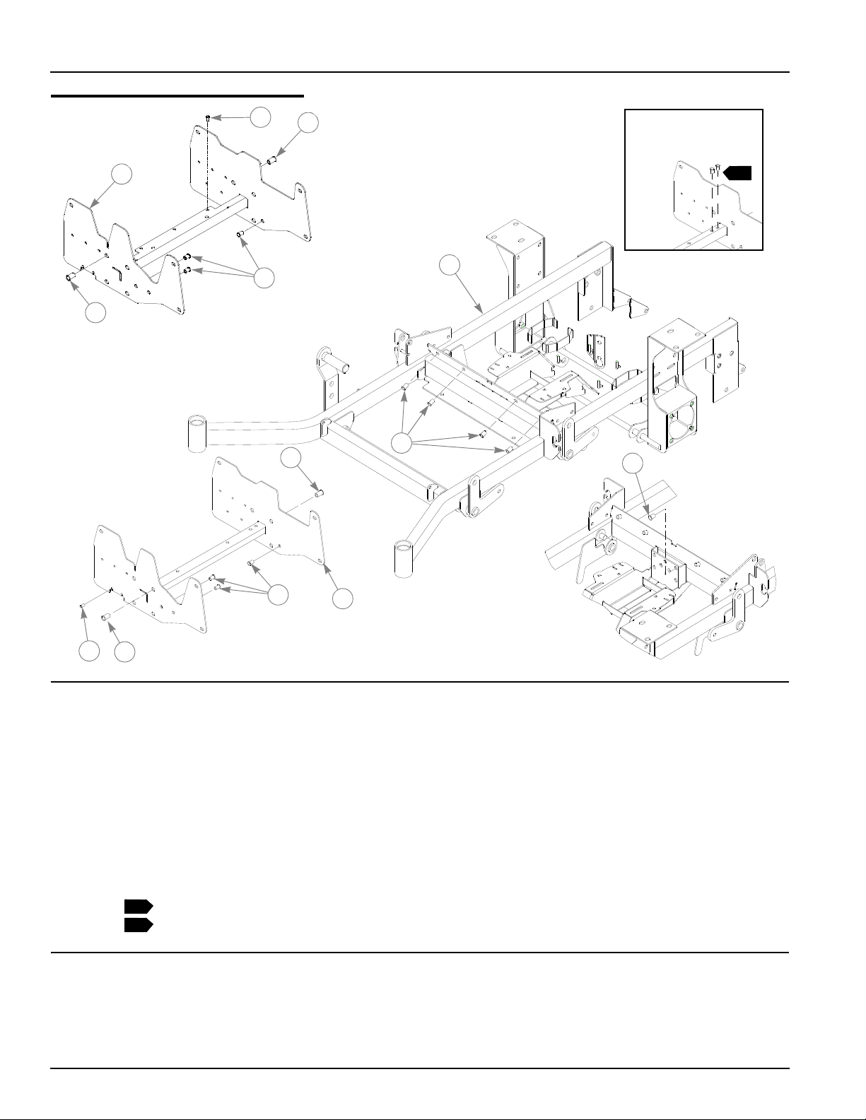
Rivet Nut Installation
1
2
2
2
3
2
FOR KAW ASAKI
26 HP LIQUID
COOLED ONLY
6
3
2
3
3
4
5
FOR ALL MOWERS
EXCEPT 26 HP
LIQUID COOLED
4
1
1
ITEM NO.
1 548032 107701 1 TRACTOR FRAME (54" SIDE DISCHARGE)
2 808493 808493 13 3/8-16 THREAD RIVET NUT
3 600961 600961 8 1/2-13 THREAD RIVET NUT
4 808477 808477 2 1/4-20 THREAD RIVET NUT (KAW AIR COOLED ONLY)
4 808477 808477 3 1/4-20 THREAD RIVET NUT (KAW LIQUID COOLED ONLY)
5 547950 106732 1 XR7 MMZ SEAT SUPPORT
6 549303 109678 1 SEAT SUPPORT
SERVICE
PART NO.
MFG. PART
NO.
547760 106211 1 TRACTOR FRAME (60" SIDE DISCHARGE)
547752 106039 1 TRACTOR FRAME (66" SIDE DISCHARGE)
548545 108093 1 TRACTOR FRAME (54" REAR DISCHARGE)
QTY. DESCRIPTION
NOTES:
1. Seat supports 547950 and 549303 include rivet nuts.
2. Mowers with serial numbers prior to 08010000 require (2) of 808493
(Rivet Nut 3/8-16 thread).
2-2 108602 10/08
Page 11
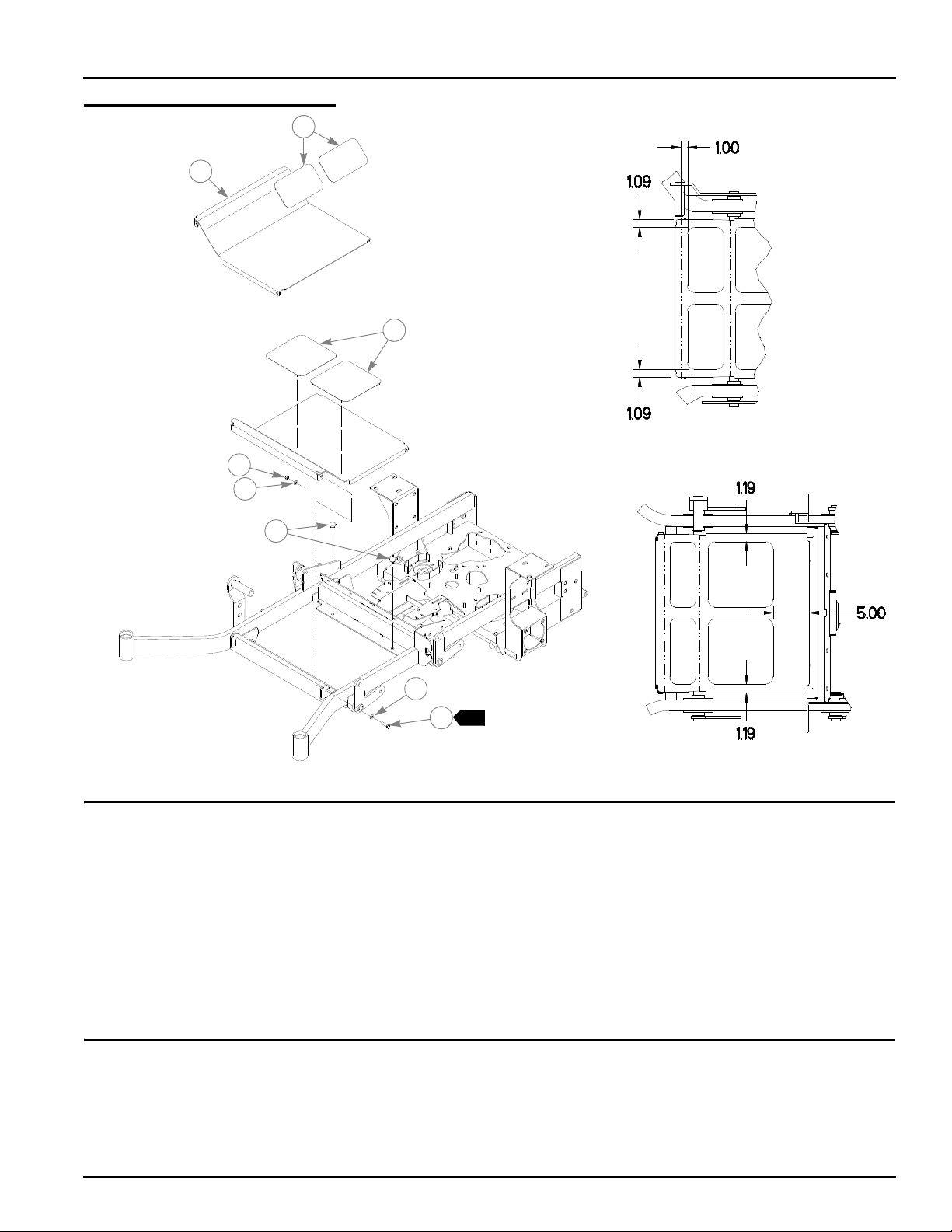
Footrest Assembly
1
2
1
3
4
5
5
6
7
ITEM
NO.
1 359547 359547 2 STEP TREAD
2 395533 395533 1 FLOOR
3 305615 305615 2 PLATFORM STEP TREAD
4 086660 086660 2 NT .375-16 HX LK NY
5 767954 767954 4 FW .406 X .812 X .060 SAE HD ZN
6 781880 781880 2 RUBBER BUMPER
7 052860 052860 2 CS .375-16 X 1.250 HX G5 ZN
SERVICE
PART NO.
MFG.
PART NO.
QTY DESCRIPTION
NOTES:
1. Do not tighten, Item 2 (348276 Floor) must be able to pivot on these
bolts.
108602 10/08 2-3
Page 12

2-4 108602 10/08
Page 13

Chapter 3 Contents
Hydraulic System Installation—S/N 07120009 and higher . . . . . . . . 3-2
Hydraulic System Installation—S/N prior to 07120009 . . . . . . . . . . . 3-6
108602 10/08 3-1
Page 14
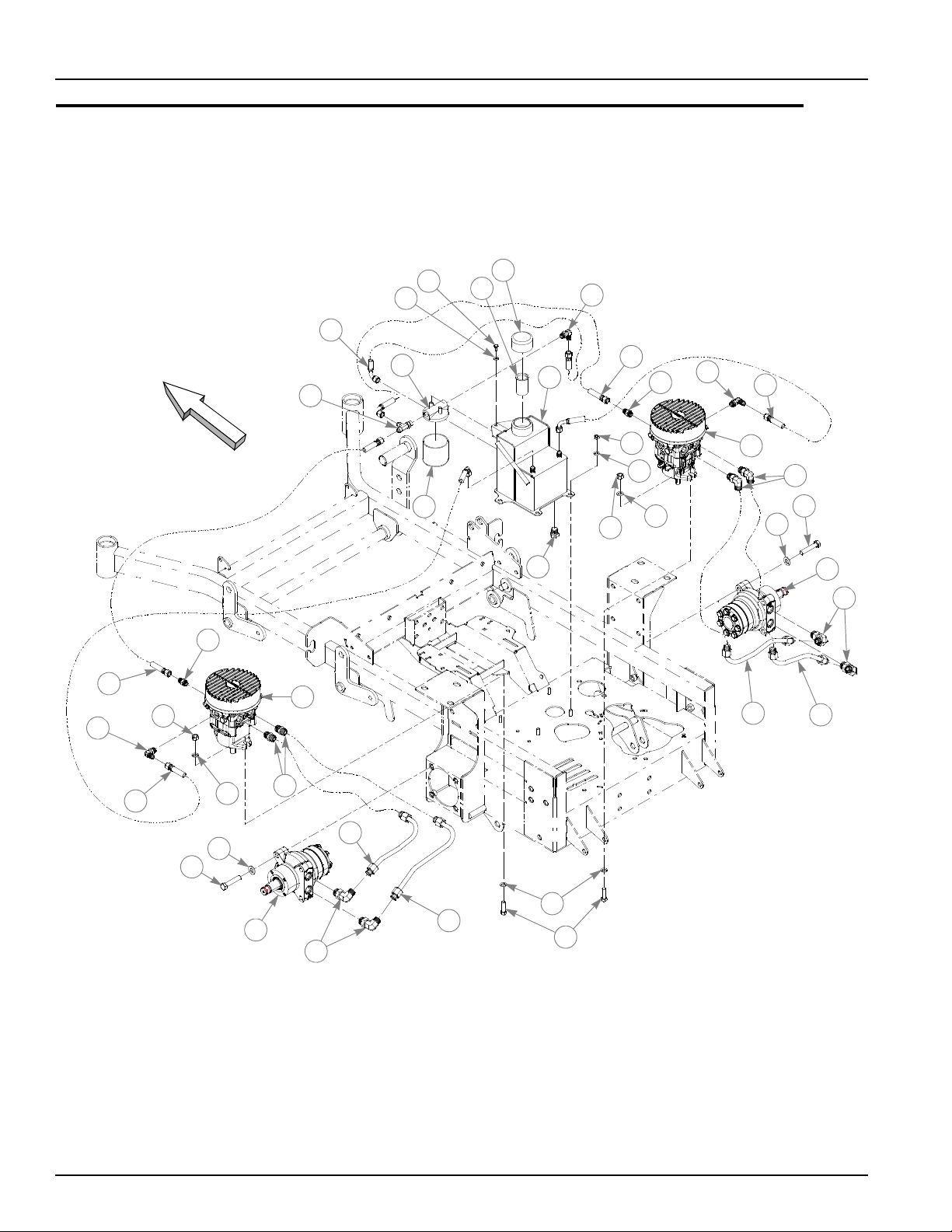
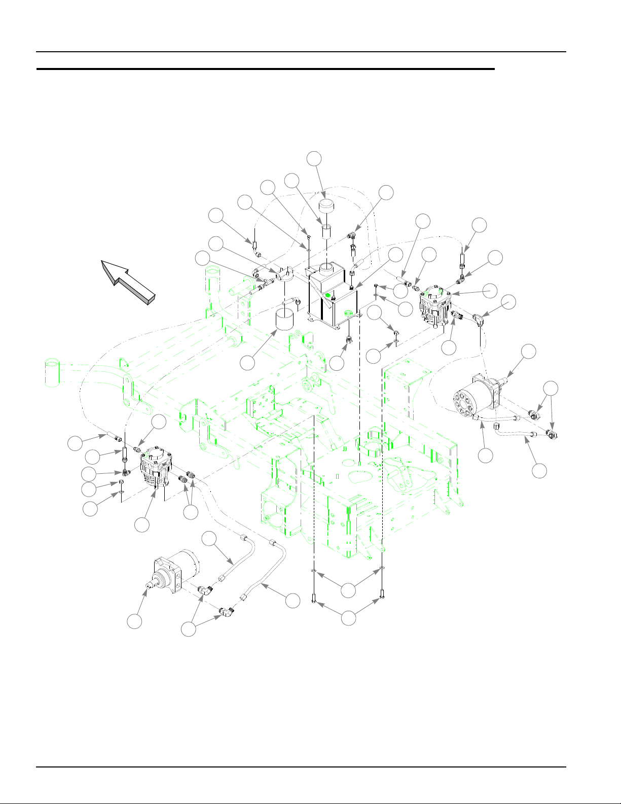
Hydraulic System Installation—S/N 07120009 and higher
FRONT
18
1
32
2
3
4
19
20
5
6
7
22
21
19
10
11
24
12
25
26
27
9
30
11
10
20
22
14
31
15
19
11
13
28
25
12
29
8
17
16
16
17
23
3-2 108602 10/08
Page 15

Hydraulic System Installation—S/N 07120009 and higher
ITEM
NO.
1 768515 768515 2 FW .281 X .625 X .051/.080 HD ZN/YL
2 055947 055947 2 CS .250-20 X .500 HX G5 ZN
3 032771 032771 1 STRAINER
4 032763 032763 1 BREATHER CAP
5 548636 349860 1 RESERVOIR
6 034272 034272 4 NT .312-18 HX G5 ZN
7 768523 768523 4 FW .343 X .687 X .051/.080 HD ZN/YL
8 601133 601133 1 PUMP, HYD 12CC W/ FAN RH
9 601134 601134 1 PUMP, HYD 12CC W/ FAN LH
10 041707 041707 4 NT .437-14 HX G5 ZN
11 704742 704742 8 FW .453 X .812 X .060 ZN
12 600922 600922 2 MOTOR, HGM-15E-3138
13 705186 705186 4 CS .437-14 X 1.375 HX G5 ZN
14 768341 768341 1 FILTER ELEMENT
15 768333 768333 1 FILTER HEAD
16 767962 767962 8 FW .531X 1.063X.090 SAE
17 008573 008573 8 CS .500-13X2.500 HX G5
18 781575 N/A 1 -6STR -6 90°, PUSHLOC HOSE 4.75"
19 763946 N/A 3 90°, -6 O-RING/-6 JIC FITTING
20 601252 N/A 2 CASE DRAIN ASSY
21 781591 N/A 1 -6STR -6 90°, PUSHLOC HOSE, 15.00"
22 779132 N/A 2 STR-6MORB/-6JIC FITTING
23 781542 N/A 2 90°,-8MORB/-8MSL FITTING
24 781658 N/A 1 STR-8-MORB/HEX PLUG
25 781526 N/A 4 90°, -10MORB/-8MSL FITTING
26 781500 N/A 1 RIGHT LOOP/RP-BM HYDRO TUBE
27 600915 N/A 1 TUBE, LP-TM RT LOOP
28 781484 N/A 1 LEFT LOOP/RP-BM HYDRO TUBE
29 781476 N/A 1 LEFT LOOP/LP-TM HYDRO TUBE
30 781534 N/A 2 STR-8MORB/-8MSL FITTING
31 781518 N/A 1 -6STR -6STR PUSHLOC HOSE, 9.00"
32 763953 N/A 1 -6 O-RING/-6JIC/6JIC T FITTING
SERVICE
PART NO.
N/A 600913 1 HYDRAULIC KIT (INCLUDES 16-31)
MFG.
PART NO.
QTY DESCRIPTION
NOTES:
1. Hydraulic system capacity is 5 US quarts of 20W50 motor oil. Fill
reservoir to within 1" of top of Item 3 (032771 Strainer). See “Hydraulic
system” on page 10-24.
108602 10/08 3-3
Page 16

Note:
HYDRAULIC SYSTEM CHARGING PROCEDURE
1. Set handles in the neutral position.
2. Start engine at idle.
3. Let run for a minimum of 30 seconds.
4. Stroke handles to forward position.
5. If motors do not turn in 15 seconds return handles to neutral and
repeat step 3 and 4 (one time).
6. If motors do not turn after second attempt, shut off the engine
and check for oil at the pump.
7. Increase throttle to half speed and work handles through forward
and reverse position until the motor operates smoothly
throughout the entire speed range.
Seal Kit for hydraulic pump; 727756 (BDP10 Overhaul Seal Kit)
3-4 108602 10/08
Page 17

This page intentionally left blank.
108602 10/08 3-5
Page 18
Hydraulic System Installation—S/N prior to 07120009
8
22
FRONT
16
1
31
2
3
4
17
18
5
6
7
20
19
17
21
10
11
23
12
24
25
26
9
29
11
10
18
20
14
30
15
17
11
13
27
24
12
28
3-6 108602 10/08
Page 19

Hydraulic System Installation—S/N prior to 07120009
ITEM
NO.
1 768515 768515 2 FW .281 X .625 X .051/.080 HD ZN/YL
2 055947 055947 2 CS .250-20 X .500 HX G5 ZN
3 032771 032771 1 STRAINER
4 032763 032763 1 BREATHER CAP
5 548636 349860 1 RESERVOIR
6 034272 034272 4 NT .312-18 HX G5 ZN
7 768523 768523 4 FW .343 X .687 X .051/.080 HD ZN/YL
8 781062 781062 1 HYDRO-GEAR PUMP, BDP-10A-300
9 781047 781047 1 HYDRO-GEAR PUMP BDP-10A-400
10 041707 041707 4 NT .437-14 HX G5 ZN
11 704742 704742 8 FW .453 X .812 X .060 ZN
12 781054 781054 2 ROSS/PARKER WHEEL MOTOR, MB-15
13 705186 705186 4 CS .437-14 X 1.375 HX G5 ZN
14 768341 768341 1 FILTER ELEMENT
15 768333 768333 1 FILTER HEAD
16 781575 N/A 1 -6STR -6 90°, PUSHLOC HOSE 4.75"
17 763946 N/A 3 90°, -6 O-RING/-6 JIC FITTING
18 778985 N/A 2 -6STR -6 90°, PUSHLOC HOSE, 13.00"
19 781591 N/A 1 -6STR -6 90°, PUSHLOC HOSE, 15.00"
20 779132 N/A 2 STR-6MORB/-6JIC FITTING
21 781559 N/A 1 45°, -8MORB/-8MSL FITTING
22 781542 N/A 1 90°,-8MORB/-8MSL FITTING
23 781658 N/A 1 STR-8-MORB/HEX PLUG
24 781526 N/A 4 90°, -10MORB/-8MSL FITTING
25 781500 N/A 1 RIGHT LOOP/RP-BM HYDRO TUBE
26 781492 N/A 1 RIGHT LOOP/LP-TM HYDRO TUBE
27 781484 N/A 1 LEFT LOOP/RP-BM HYDRO TUBE
28 781476 N/A 1 LEFT LOOP/LP-TM HYDRO TUBE
29 781534 N/A 2 STR-8MORB/-8MSL FITTING
30 781518 N/A 1 -6STR -6STR PUSHLOC HOSE, 9.00"
31 763953 N/A 1 -6 O-RING/-6JIC/6JIC T FITTING
SERVICE
PART NO.
N/A 781469 1 MMZ HYDRAULIC KIT (INCLUDES 16-31)
MFG.
PART NO.
QTY DESCRIPTION
NOTES:
1. Hydraulic system capacity is 5 US quarts of 20W50 motor oil. Fill
reservoir to within 1" of top of Item 3 (032771 Strainer). See “Hydraulic
system” on page 10-24.
108602 10/08 3-7
Page 20

Note:
HYDRAULIC SYSTEM CHARGING PROCEDURE
1. Set handles in the neutral position.
2. Start engine at idle.
3. Let run for a minimum of 30 seconds.
4. Stroke handles to forward position.
5. If motors do not turn in 15 seconds return handles to neutral and
repeat step 3 and 4 (one time).
6. If motors do not turn after second attempt, shut off the engine
and check for oil at the pump.
7. Increase throttle to half speed and work handles through forward
and reverse position until the motor operates smoothly
throughout the entire speed range.
Seal Kit for hydraulic pump; 727756 (BDP10 Overhaul Seal Kit)
3-8 108602 10/08
Page 21

Chapter 4 Contents
Battery Installation. . . . . . . . . . . . . . . . . . . . . . . . . . . . . . . . . . . . . . . 4-2
Deck Lift Assembly . . . . . . . . . . . . . . . . . . . . . . . . . . . . . . . . . . . . . . 4-4
Steering and Park Brake Assembly. . . . . . . . . . . . . . . . . . . . . . . . . . 4-6
Steering Sub-Assembly. . . . . . . . . . . . . . . . . . . . . . . . . . . . . . . . . . . 4-9
Pump Belt and Pulleys Installation . . . . . . . . . . . . . . . . . . . . . . . . . 4-10
108602 10/08 4-1
Page 22
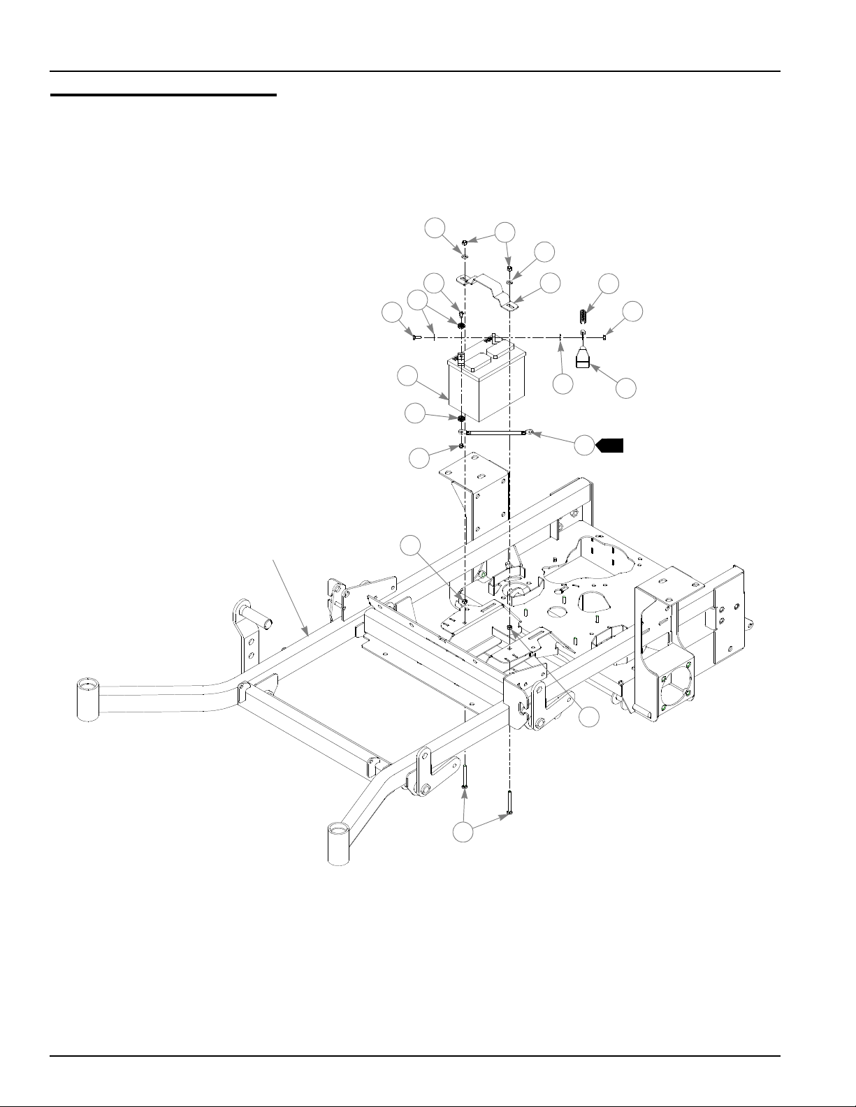
Battery Installation
1
TRACTOR
FRAME
11
12
9
9
10
8
4
1
3
1
6
5
8
5
7
2
11
9
4-2 108602 10/08
Page 23

Battery Installation
ITEM
NO.
1 024927 024927 2 NT .250-20 HX GR.5 ZN
2 771428 771428 1 RED BATTERY CABLE BOOT
3 796219 796219 1 36" NEGATIVE BATTERY CABLE
4 744276 744276 1 POSITIVE BATTERY CABLE
5 768523 768523 3 FW .343 X .687 X .051/.080 HD ZN/YL
6 058776 058776 2 NT .312-18 HX NL ZN
7 348417 348417 1 BATTERY CLAMP STRAP
8 055939 055939 2 CS .250-20 X .750 HX G5 ZN
9 029868 029868 4 LW .250 INT-EXT TOOTH ZN
10 740696 740696 1 BATTERY
11 034272 034272 2 NT .312-18 HX G5 ZN
12 779850 779850 2 CB .312-18 X 3.00 FUL ZN
SERVICE
PART NO.
MFG.
PART NO.
QTY DESCRIPTION
NOTES:
1. When performing service on mower, disconnect battery ground cable
and do not reconnect to battery until engine is ready to be started. See
Owners Manual.
2. Battery is not installed in export models.
108602 10/08 4-3
Page 24
Deck Lift Assembly
1
TRACTOR
FRAME
1
1
1
4
1
3
2
5
5
5
5
5
4
4
5
6
8
8
4
4
4
4
14
13
9
7
10
10
4
10
11
12
8
10
6
9
9
4-4 108602 10/08
Page 25

Deck Lift Assembly
ITEM
NO.
1 348318 348318 1 STOP HANDLE
2 600437 600437 1 DECK HEIGHT 1/2" PIN W/A
3 783001 783001 1 DECK LIFT INDICATOR SUBASSEMBLY
4 704643 704643 8 NT .437-14 HX FLG ZN
5 781294 781294 7 CLIP E, 1.00 X .625 X .050
6 782995 782995 2 DECK LIFT SPRING SUBASSEMBLY
7 781229 781229 1 CE .750 X 2.25 X 1.75 HEADLESS
8 055749 055749 3 CS .437-14 X 1.750 HX G5 ZN
9 348391 018846 4 DECK LIFT CHAIN
10 015495 015495 4 STRAIGHT GREASE FITTING
11 034272 034272 1 NT .312-18 HX G5 ZN
12 756270 756270 1 CS .312-18 X 1.50 FUL THR GR5 ZN
13 348458 348458 1 DECK LEVELER YOKE
14 781831 781831 1 CS .437-14 X 1.750 FUL THD G5 ZN
SERVICE
PART NO.
MFG.
PART NO.
QTY DESCRIPTION
NOTES:
1. Apply grease to zerks (see owner’s manual).
108602 10/08 4-5
Page 26
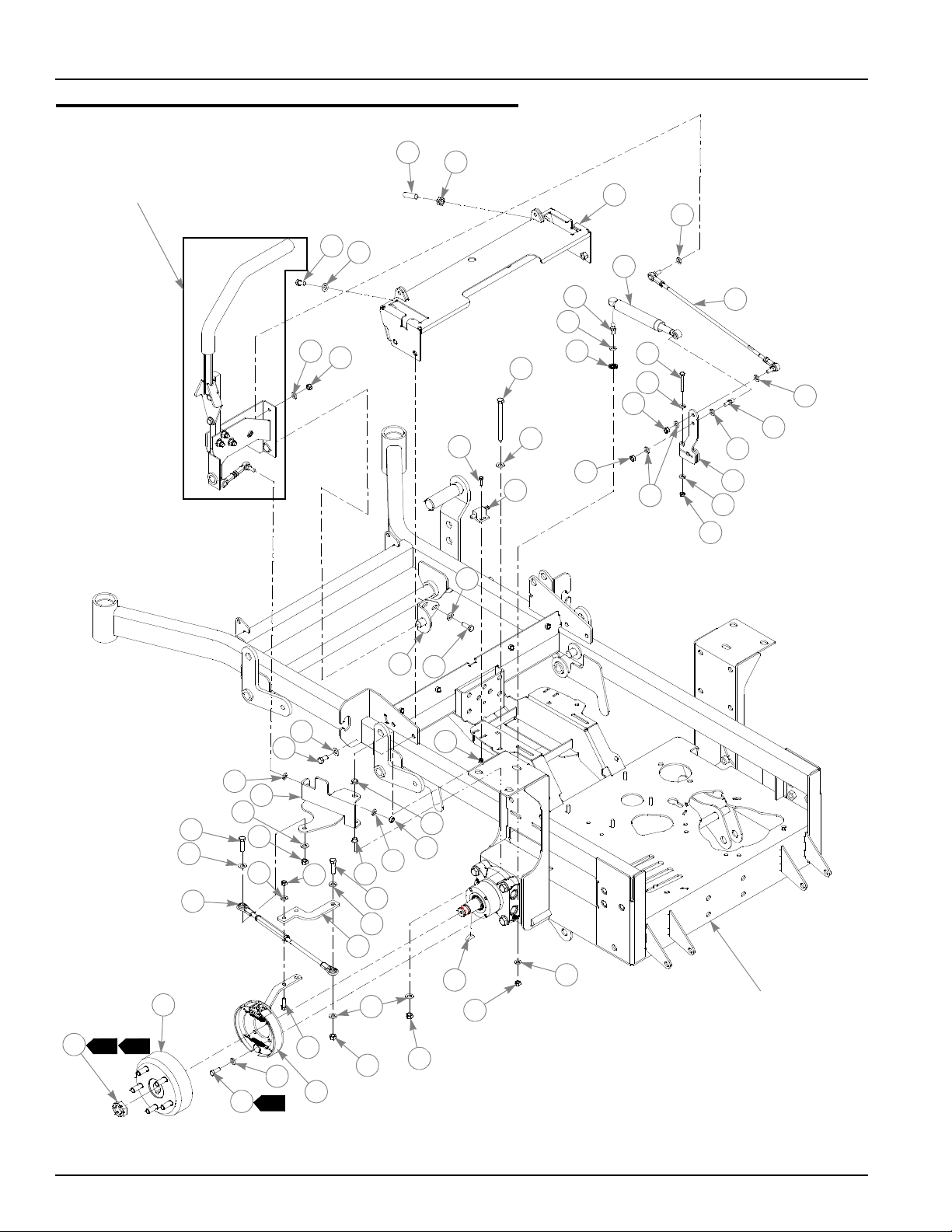
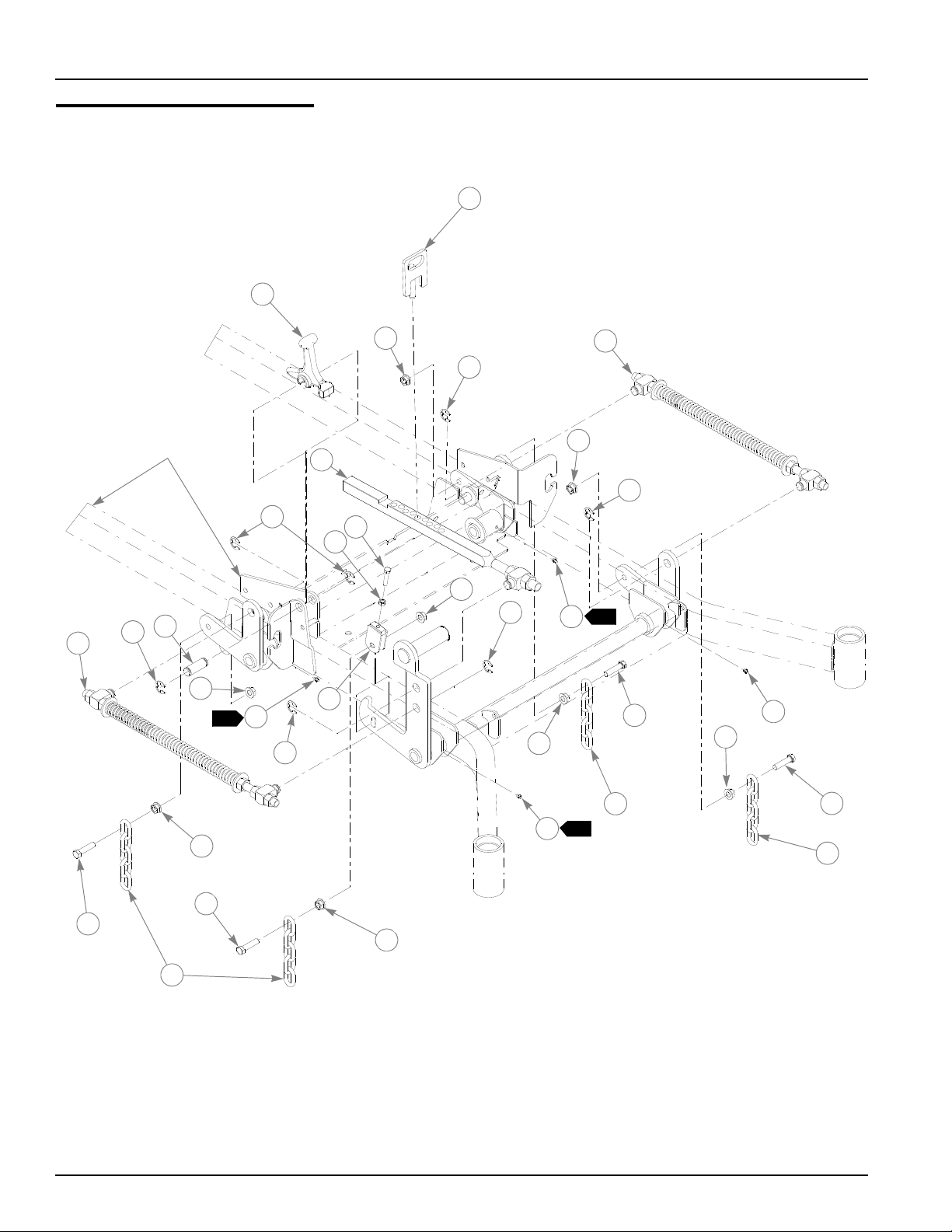
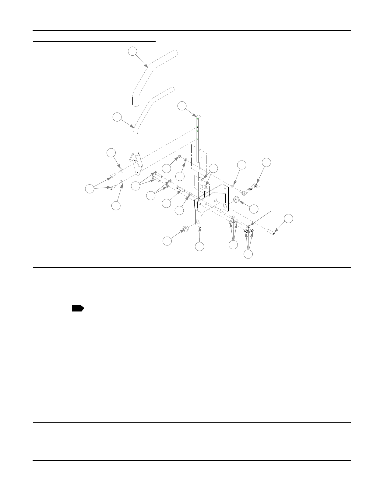
Steering and Park Brake Assembly
TRACTOR
FRAME
1
2
20
6
19
4
5
23
5
25
25
26
29
7
28
6
6
21
28
24
5
23
32
30
31
34
5
27
5
35
6
7
16
17
18
6
8
6
11
5
10
22
9
4
5
2
3
1
6
10
6
12
13
14
14
15
6
7
22
6
5
22
SEE STEERING
SUB-ASSEMBLY
page 4-9
6
33
4
4-6 108602 10/08
Page 27

Steering and Park Brake Assembly
87335
6
5
6
87878
7
ITEM
NO.
1 348987 348987 1 STEERING CONTROL PANEL
2 781716 781716 2 SS .500-13 X 1.75 SH ZN
3 053199 053199 2 NT .500-13 HX JAM ZN
4 055822 055822 8 CS .375-16 X .750 HX G5 ZN
5 767954 767954 26 FW .406 X .812 X .060 SAE HD ZN
6 768523 768523 30 FW .343X .687 X .051/.080 HD ZN/YL
7 023655 023655 6 NT .312-24 HXZY NL
8 781286 781286 2 PUMP ROD ADJUSTER ASSEMBLY
9 600221 600221 2 CENTERING DAMPER
10 781922 781922 4 DAMPER BALL STUD
11 029876 029876 2 LW .312 INT-EXT TOOTH Z
12 367557 367557 2 PUMP ARM
13 704163 704163 2 CS .250-20 X 2.00 HX G5 ZN
14 768515 768515 4 FW .281 X .625 X .051/.080 HD ZN/YL
15 068551 068551 2 NT .250-20 HX NL ZN
16 782979 782979 2 CS .375-16 X 4.75 HX G5 ZN
17 063198 063198 4 CS 10-24 X .750 HXFLK ZN
18 781211 781211 2 PUSH BUTTON SWITCH
19 348797 348797 2 ADJUSTABLE PIVOT
20 036244 036244 6 CS .375-16 X 1.000 HX G5 ZN
21 059832 059832 4 NT #10-24 HX NL ZN
22 034272 034272 8 NT .312-18 HX G5 ZN
23 054502 054502 4 NT .375-16 HX GRD 5 ZN
24 101766 101766 2 BRAKE ARM EXTENSION
25 005116 005116 4 CS .375-16 X 1.375 HX G5 ZN
26 350397 350397 2 BRAKE LINK TURNBUCKLE
27 350330 350330 1 L.S. BRAKE PIVOT ARM
28 765339 765339 4 BUSHING
29 086660 086660 2 NT .375-16 HX LK NY
30 600925 600925 1 BRAKE ASSY LEFT WHEEL
30 781112 781112 1 BRAKE ASSY LH (S/N PRIOR TO 07120009)
31 600923 600923 2 WHEEL HUB
32 036236 036236 4 CS .312-18 X 1.000 HX G5 ZN
33 064014 064014 8 CS .312-18X .875 HX G5
34 601289 N/A 2 HG MOTOR NUT
35 601290 N/A 2 HG MOTOR KEY
SERVICE
PART NO.
350272 350272 2 BRAKE ARM EXTENSION
350264 350264 1 R.S. BRAKE PIVOT ARM
600924 600924 1 BRAKE ASSY RIGHT WHEEL
781351 781351 1 BRAKE ASSY RH (S/N PRIOR TO 07120009)
781765 781765 2 BRAKE DRUM-HUB ASSEMBLY
065516 N/A 2 ROSS CASTLE NUT
064337 N/A 2 ROSS KEY
MFG.
PART NO.
QTY DESCRIPTION
NOTES:
1. For units with serial number 07120009 and higher: Torque to 180-210
ft.-lbs. Included with wheel motor.
108602 10/08 4-7
Page 28

2. For units with serial number 07120009 and higher: Torque to 17 ft.-lbs.
3. For units with serial number 07120009 and higher: 600925 used on left
wheel. 600924 used on right wheel.
4. For units with serial numbers prior to 07120009: Torque to 350-375 ft.lbs. Included with wheel motor.
5. For units with serial numbers prior to 07120009: Torque brake assembly
mounting bolts to 100 ft.-lbs.
6. For units with serial numbers prior to 07120009: 781112 used on left
wheel. 781351 used on right wheel.
7. Used on mowers with serial numbers prior to 07120009.
8. Used on mowers with serial numbers 07120009 and higher.
4-8 108602 10/08
Page 29
Steering Sub-Assembly
2
3
4
5
7
6
8
9
14
10
12
13
3
5
3
11
1
3
10
3
7
1
ITEM NO.
1 781260 N/A 2 STEERING BAR GRIP
2 348755 348755 2 STEERING BAR
3 767954 767954 16 FW .406 X .812 X .060 SAE HD ZN
4 036244 036244 4 CS .375-16 X 1.000 HX G5 ZN
5 705178 705178 6 CS .375-16 X 1.750 HX G5 ZN
6 023655 023655 2 NT .312-24 HXZY NL
7 768523 768523 4 FW .343X .687 X .051/.080 HD ZN/YL
8 348946 348946 2 STEERING ARM MOUNT
9 348888 348888 1 STEERLEVER SUPPORT LH (SHOWN)
10 781153 781153 4 BUSHING
11 781716 781716 2 SS .500-13 X 1.75 SH ZN
12 781583 781583 2 BRAKE ROD ASSEMBLY
13 086660 086660 6 NT .375-16 HX LK NY
14 348862 348862 4 STEERLEVER BUSHING
SERVICE
PART NO.
348714 348714 1 STEERLEVER SUPPORT RH
MFG. PART
NO.
QTY. DESCRIPTION
NOTES:
1. Includes Item 1 (781260 Steering Bar Grip).
108602 10/08 4-9
Page 30
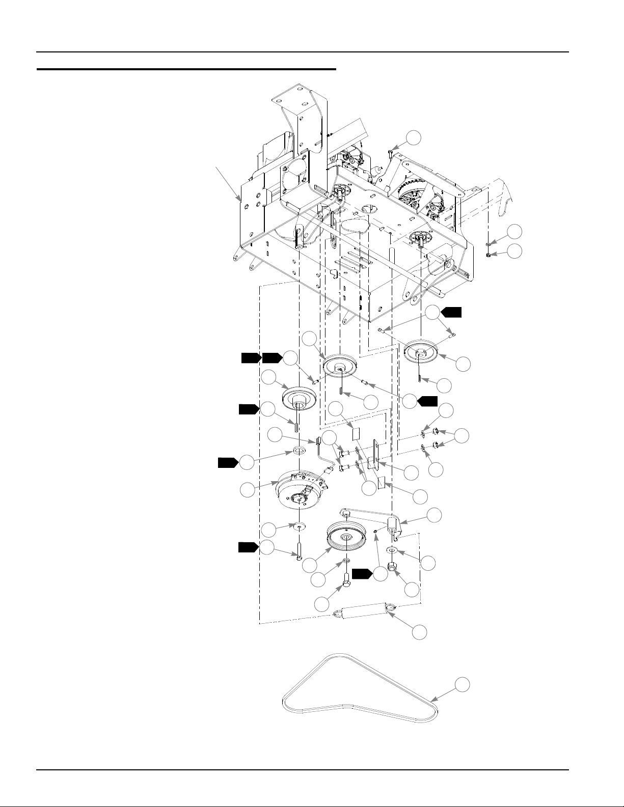
Pump Belt and Pulleys Installation
3
2
TRACTOR
FRAME
1
2
2
1
6
7
11
6
4
14
16
17
15
18
19
20
12
10
21
22
2
5
13
8
7
3
10
10
8
9
23
24
25
26
13
5
6
27
7
7
4-10 108602 10/08
Page 31

Pump Belt and Pulleys Installation
5
6
ITEM
NO.ITE
M NO.
1 779876 779876 1 ENGINE SC SINGLE PULLEY
2 212076 212076 1 KEY 1/4 SQ X 1.50 LONG
3 601311 601311 1 WARNER CLUTCH
4 783829 783829 1 FW .460 X 1.750 X .250 ZNYC
5 785659 785659 1 CS .437-20 X 2.50 HX G5 ZNYC
6 083196 083196 4 SS .312-18 X .750 SQ-HD ZN
7 768127 768127 2 KEY 5MM X 30MM RADIUS ENDS
8 768705 768705 2 PULLEY
9 008193 008193 2 NT .500-13 HX G5 ZNYC
10 767962 767962 4 FW .531 X 1.063 X .090 SAE HD ZN
11 016527 016527 2 CS .500-13 X 1.00 HX G5 ZNYC
12 366765 366765 1 CLUTCH ANCHOR ANGLE
13 784918 784918 2 RUBBER BUMPER
14 349761 349761 1 PUMP IDLER ARM
15 015495 015495 1 STRAIGHT GREASE FITTING
16 025296 025296 1 FW .760 X 1.625 X .08 ZN
17 061101 061101 1 NT .750-10 HX NL ZN
18 781856 781856 1 IDLER PULLEY
19 028118 028118 1 FW .62 X 1.00 X.134 ZN
20 781872 781872 1 CS .625-11X1.25 HX G5 ZN
21 601016 601016 1 IDLER SPRING
22 781443 781443 1 A-SEC PUMP IDLER BELT
23 791251 791251 1 HARNESS, CLUTCH PIGTAIL (DIODE)
24 036236 036236 1 CS .312-18X1.000 HX G5 ZNYC
25 768523 768523 1 FW .343 X .687 X .051/.080 HD ZNYC
26 034272 034272 1 NT .312-18 HX G5 ZNYC
27 797654 797654 1 CLUTCH SPACER MNZ
SERVICE
PART NO.
325308 325308 2 PULLEY & FAN
MFG.
PART NO.
QTY DESCRIPTION
NOTES:
1. Torque to 45-48 ft-lbs.
2. Torque to 12-15 ft-lbs.
3. Apply grease at zerk (see owner’s manual).
4. Included with Honda 24 HP engine (785014).
5. For mowers with serial numbers prior to 07060569 order clutch 787366.
6. For mowers with serial numbers prior to 07120009 use 325308 (pulley
with fan).
7. Used on mowers with Kawasaki 29 HP engines only.
108602 10/08 4-11
Page 32

4-12 108602 10/08
Page 33

Chapter 5 Contents
Kawasaki Engine Installation (Remote Air Cleaner) . . . . . . . . . . . . . 5-2
Kawasaki 25 HP Engine Installation (With HD Air Cleaner) . . . . . . . 5-6
Kawasaki 26 HP Engine Installation . . . . . . . . . . . . . . . . . . . . . . . . . 5-8
Kawasaki 29 HP Engine Installation (With HD Air Cleaner) . . . . . . 5-10
Honda Engine Installation . . . . . . . . . . . . . . . . . . . . . . . . . . . . . . . . 5-12
Kohler Engine Installation . . . . . . . . . . . . . . . . . . . . . . . . . . . . . . . . 5-16
Fuel System Installation (Air Cooled Engines) . . . . . . . . . . . . . . . . 5-18
Fuel System Installation (Liquid Cooled Engines). . . . . . . . . . . . . . 5-20
Instrument Panel Assembly (Air Cooled). . . . . . . . . . . . . . . . . . . . . 5-22
Instrument Panel Assembly (Liquid Cooled) . . . . . . . . . . . . . . . . . . 5-24
Electrical Schematic (799320). . . . . . . . . . . . . . . . . . . . . . . . . . . . . 5-26
Electrical Schematic—Kawasaki LC (799338) . . . . . . . . . . . . . . . . 5-27
108602 10/08 5-1
Page 34
Kawasaki Engine Installation (Remote Air Cleaner)
RED
TO ENGINE
SENSOR
TO BULLET
TERMINALS
TO SPADE
TERMINAL
YELLOW
16
2
RED/BLK
2
2
TRACTOR
FRAME
POSITIVE
BATTERY
CABLE
2
1
6
2
7
5
18
25
11
16
17
27
3
31
33
30
29
20
3
19
26
39
32
8
4
17
7
7
6
6
NEGATIVE
BATTERY
CABLE
9
STARTER
SOLENOID
GROUND
10
6
12
13
14
3
15
15
3
3
2
17
23
20
3
21
3
24
3
24
3
28
34
35
38
36
37
1
PART OF COMMON
WIRE HARNESS
40
PART OF
ENGINE
7
3
22
5
PUR 2
BLK
5-2 108602 10/08
Page 35

Kawasaki Engine Installation (Remote Air Cleaner)
ITEM
NO.
1 777656 777656 1 KAWASAKI 23 HP ENGINE
2 058776 058776 4 NT .312-18 HXZY NL
3 768523 768523 24 FW .343 X .687 X .051/.080 HD ZN/YL
4 029876 029876 1 LW .312 INT-EXT TOOTH ZN
5 792762 792762 1 BATTERY CABLE
6 768515 768515 5 FW .281 X .625 X .051/.080 HD ZN/YL
7 024927 024927 3 NT .250-20 HX GR.5 ZN
8 799312 799312 1 WIRE HARNESS ADAPTER
9 799320 799320 1 COMMON WIRE HARNESS
10 044255 044255 1 NT #10-32 HX ZN
11 030817 030817 1 STARTER SOLENOID
12 055947 055947 2 CS .250-20 X .500 HX G5 ZN
13 792192 792192 1 STARTER RELAY GROUND WIRE
14 771428 771428 1 RED BATTERY CABLE BOOT
15 050161 050161 4 CS .312-18 X 1.75 HX G5
16 786673 786673 1 DONALDSON AIR CLEANER CAP
17 057661 057661 3 HOSE CLAMP
18 788943 788943 1 AIR FILTER INDICATOR
19 785741 785741 1 MOUNTING BAND
20 034272 034272 6 NT .312-18 HX G5 ZN
21 601216 601216 1 FITTING 90° STREET ELBOW
22 782763 782763 1 AIR CLEANER
23 366443 366443 1 REMOTE AIR CLEAN MOUNT BRACKET
24 036236 036236 6 CS .312-18 X 1.00 HX G5 ZNYC
25 786038 786038 1 REMOTE AIR FILTER HOSE
26 796524 796524 1 OIL DRAIN M20 X 2.5 VALVE
27 350371 350371 1 MUFFLER GUARD
28 349704 349704 1 ENGINE CAGE MOUNT PLATE
29 767962 767962 4 FW .531 X 1.063 X .090 SAE HD ZN
30 016527 016527 4 CS .500-13 X 1.00 HX G5 ZN
31 064006 064006 2 CS .312-18 X .625 HX G5 ZN
32 781732 781732 1 MUFFLER MANIFOLD
33 781724 781724 1 MUFFLER
34 720177 720177 2 CS M 8-1.25 X 20 10.9 HXFL ZN
35 782649 782649 1 KAW (23) EXHAUST PIPE CLAMP
36 782664 782664 4 NT M8-1.25 HX STAINLESS STEEL
37 017004 017004 4 LW .312 MED SPRING ZN
38 360693 360693 1 HEAT SHIELD
39 780841 780841 2 KAW (23) MUFFLER GASKET
40 789131 789131 1 HUSTLER Z FAN CONNECTOR CAP
SERVICE
PART NO.
782318 782318 1 KAWASAKI 25 HP ENGINE (FH721V, 3600 RPM)
MFG.
PART NO.
QTY DESCRIPTION
108602 10/08 5-3
Page 36

NOTES:
1. Includes mounting hardware.
2. Part of Item 8 (799312 Wire Harness Adapter).
3. Engine oil capacity: Refer to engine owner’s manual.
4. Engine RPM to be set at 3600± 50.
5. Includes one (1) of Item 17 (057661 Hose Clamp).
6. When installing lower hose clamp on air cleaner hose, install as low as
possible (against carburetor inlet).
7. This connector used for optional electrical equipment.
8. Air filter service parts:
785261 MAIN AIR FILTER ELEMENT
763318 VACUATOR VALVE
5-4 108602 10/08
Page 37

This page intentionally left blank.
108602 10/08 5-5
Page 38

Kawasaki 25 HP Engine Installation (With HD Air Cleaner)
1
34
2
3
4
5
7
5
6
8
9
5
10
12
13
14
15
16
17
18
19
20
4
5
22
21
2
24
23
2
TO ENGINE
SENSOR
YELLOW
PART OF
ENGINE
STARTER
SOLENOID
GROUND
26
TO BULLET
TERMINALS
2
TO SPADE
TERMINAL
2
25
28
23
24
29
31
24
23
30
24
6
5
32
PURPLE
2
27
33
RED/BLK
11
5
1
PART OF COMMON
WIRE HARNESS
5
5-6 108602 10/08
Page 39

Kawasaki Engine Installation (With HD Air Cleaner)
ITEM
NO.
1 601119 601119 1 KAWASAKI 25 HP ENGINE W/ H/D AIR
2 601257 601257 1 FITTING, 90 1/8NPT BRASS
3 788943 788943 1 AIR FILTER INDICATOR
4 058776 058776 4 NT .312-18 HXZY NL
5 768523 768523 12 FW .343 X .687 X .051/.080 HD ZN/YL
6 050161 050161 4 CS .312-18 X 1.75 HX G5
7 796524 796524 1 OIL DRAIN M20 X 2.5 VALVE
8 350371 350371 1 MUFFLER GUARD
9 349704‘ 349704 1 ENGINE CAGE MOUNT PLATE
10 064006 064006 2 CS .312-18 X .625 HX G5 ZN
11 767962 767962 4 FW .531 X 1.063 X .090 SAE HD ZN
12 016527 016527 4 CS .500-13 X 1.00 HX G5 ZN
13 780841 780841 2 KAW (23) MUFFLER GASKET
14 781732 781732 1 MUFFLER MANIFOLD
15 360693 360693 1 HEAT SHIELD
16 017004 N/A 4 LW .312 MED SPRING ZN
17 782664 N/A 4 NT M8-1.25 HX STAINLESS STEEL
18 782649 782649 1 EXHAUST PIPE CLAMP
19 781724 781724 1 MUFFLER
20 720177 720177 2 CS M 8-1.25 X 20 10.9 HXFLZ
21 029876 029876 1 LW .312 INT-EXT TOOTH ZN
22 796219 N/A 1 36" NEGATIVE BATTERY CABLE
23 024927 024927 3 NT .250-20 HX GR.5 ZN
24 768515 768515 5 FW .281 X .625 X .051/.080 HD ZN/YL
25 792762 792762 1 BATTERY CABLE
26 799320 799320 1 COMMON WIRE HARNESS
27 799312 799312 1 WIRE HARNESS ADAPTER
28 044255 044255 1 NT #10-32 HX ZN
29 030817 030817 1 STARTER SOLENOID
30 055947 055947 2 CS .250-20 X .500 HX G5 ZN
31 792192 792192 1 STARTER RELAY GROUND WIRE
32 744276 N/A 1 POSITIVE BATTERY CABLE
33 771428 771428 1 RED BATTERY CABLE BOOT
34 789131 789131 1 HUSTLER Z FAN CONNECTOR CAP
SERVICE
PART NO.
MFG.
PART NO.
QTY DESCRIPTION
NOTES:
1. Includes mounting hardware.
2. Part of Item 27 (799312 Wire Harness Adapter).
3. Engine oil capacity: Refer to engine owner’s manual.
4. Engine RPM to be set at 3600± 50.
5. This connector used for optional electrical equipment.
6. Air filter service parts:
785261 MAIN AIR FILTER ELEMENT
785279 SAFTEY AIR FILTER ELEMENT
763318 VACUATOR VALVE
108602 10/08 5-7
Page 40

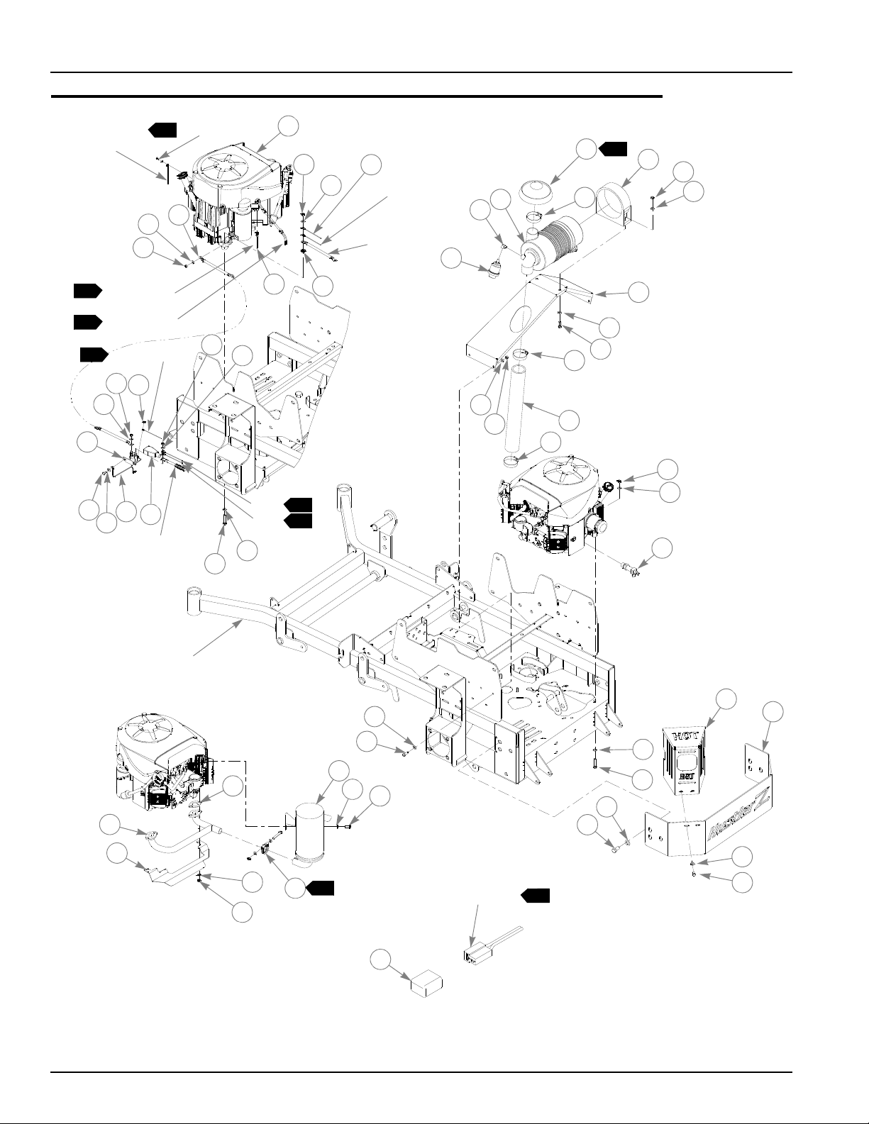
Kawasaki 26 HP Engine Installation
PART OF WIRE
HARNESS
7
30
1
2
3
4
5
6
{
1
}
6
7
8
9
8
10
KAWASAKI
ENGINE
SCREEN
PART OF
ENGINE
PART OF
ENGINE
11
11
12
12
12
13
14
17
12
15
16
20
21
22
23
29
24
25
26
9
8
19
18
30
27
28
POSITIVE
BATTERY
CABLE
NEGATIVE
BATTERY
CABLE
PUR
2
BLK
2
31
BLK
2
}
6
5-8 108602 10/08
Page 41

Kawasaki 26 HP Engine Installation
ITEM
NO.
1 795617 795617 1 KAWASAKI FD731V ENGINE
2 796748 796748 1 KAWASAKI 26HP EXHAUST MANIFOLD
3 780841 780841 2 KAW (23) MUFFLER GASKET
4 017004 017004 4 LW .312 MED SPRING ZN
5 782664 782664 4 NT M8-1.25 HX STAINLESS STEEL
6 796755 796755 1 KAWASAKI 26HP LC MUFFLER
7 785378 785378 1 1.50" MUFFLER CLAMP
8 767962 767962 14 FW .531 X 1.063 X .090 SAE HD ZN
9 016527 016527 10 CS .500-13 X 1.00 HX G5 ZN
10 008193 008193 4 NT .500-13 HX G5 ZNYC
11 064329 064329 2 CS .250-20 X .625 HX G5
12 073866 073866 4 FW .281 X .500 X .06 ZNYC
13 104133 104133 1 SCREEN SUPPORT
14 010470 010470 1 OVER CENTER LATCH ZINC
15 035626 035626 2 NT #10-24 HX ZN
16 030437 030437 2 MS #10-24 X .375 RD SL
17 024927 024927 3 NT .250-20 HX GR. 5 ZNYC
18 033035 033035 2 .12 X .75 WEATHERSTRIP (11.0" LONG)
19 033035 033035 2 .12 X .75 WEATHERSTRIP (13.375" LONG)
20 796524 796524 1 M20 X 2.5 OIL DRAIN VALVE
21 109566 109566 1 ENGINE AIR BAFFLE
22 055939 055939 3 CS .250-20 X .750 HX G5
23 768515 768515 3 FW .281 X .625 X .051/.080 HD ZN/YL
24 768523 768523 4 FW .343 X .687 X .051/.080 HD ZN/YL
25 028035 028035 4 CS M 8-1.25 X 20 HX G8.8
26 109717 109717 1 ENGINE GUARD
27 029876 029876 1 LW .312 INT-EXT TOOTH ZN
28 720516 720516 1 CS M8 X1.25 X 16 G10.9 HX
29 017004 N/A 1 LW .312 MED SPRING ZN
30 077545 N/A 1 NT M8-1.25-10-HX ZNYC
31 799338 799338 1 26HP KAWASAKI WIRE HARNESS
SERVICE
PART NO.
MFG.
PART NO.
QTY DESCRIPTION
NOTES:
1. Includes mounting hardware.
2. Part of Item 31 (799338 Tractor Wire Harness).
3. Engine oil capacity: Refer to engine owner’s manual.
4. Engine coolant capacity, 2.9 US quarts.
5. Engine RPM to be set at 3600±50.
6. Supplied with engine.
7. This connector used for optional electrical equipment.
8. Air filter service parts (see engine manual other engine service parts):
785261 MAIN AIR FILTER ELEMENT
785279 SAFETY AIR FILTER ELEMENT
108602 10/08 5-9
Page 42

Kawasaki 29 HP Engine Installation (With HD Air Cleaner)
1
2
3
4
{
5
1
6
9
8
7
10
11
11
12
13
14
15
16
17
18
19
9
8
21
20
15
22
24
25
3
26
28
YEL/BLK
3
4
RED/BLK
2
TO SPADE
TERMINAL
BULLET
3
CONNECTORS
BLK
2
PUR
3
TO SPADE
TERMINAL
NEGATIVE
BATTERY
CABLE
POSITIVE
BATTERY
CABLE
ON RECT.
ON STARTER
PUR
3
(2 WIRES)
PART OF COMMON
WIRE HARNESS
7
29
27
23
{
4
5-10 108602 10/08
Page 43

Kawasaki 29 HP Engine Installation (With HD Air Cleaner)
ITEM
NO.
1 601548 N/A 1 KAWASAKI 29 HP ENGINE
2 109743 109743 1 CABLES HEAT SHIELD
3 720516 720516 3 CS M8 X1.25 X 16 G10.9 HX
4 788018 788018 1 MUFFLER
5 785378 785378 1 1.50" MUFFLER CLAMP
6 601550 601550 1 MANIFOLD, 29/31 KAW
7 780841 780841 2 KAW MUFFLER GASKET
8 017004 017004 LW .312 MED SPRING ZN
9 782664 782664 NT M8-1.25 HX STAINLESS STEEL
10 029751 029751 2 CS .375-16 X 1.00 HXFLK ZNYC
11 705137 705137 4 FW .391 X 1.250 X .060 ZNYC
12 016899 016899 2 NT .375-16 HXFLK ZNYC
13 796524 796524 1 M20X2.5 OIL DRAIN VALVE
14 034272 034272 4 NT .312-18 HX G5 ZN
15 768523 768523 12 FW .343 X .687 X .051/.080 HD ZN/YL
16 109749 109749 1 EXHAUST HEAT SHIELD
17 338475 338475 1 MMZ TALL HEAT SHIELD
18 337394 337394 1 HUSTLER Z ENGINE GUARD
19 016253 016253 4 CB .312-18X .750 FUL ZN
20 767962 767962 6 FW .531 X 1.063 X .090 SAE HD ZN
21 016527 016527 6 CS .500-13 X 1.00 HX G5 ZN
22 036244 036244 4 CS .375-16 X 1.00 HX G5 ZNYC
23 377994 377994 1 MMZ ROLLER HEAT SHIELD
24 601257 601257 1 FITTING, 90 1/8NPT BRASS
25 788943 788943 1 AIR FILTER INDICATOR
26 029876 029876 1 LW .312 INT-EXT TOOTH ZN
27 799320 799320 1 XR7 COMMON WIRE HARNESS
28 601561 601561 1 WIRING HARNESS, KAWASAKI 29,31
29 789131 789131 1 HUSTLER Z FAN CONNECTION CAP
SERVICE
PART NO.
MFG.
PART NO.
QTY DESCRIPTION
NOTES:
1. Includes mounting hardware.
2. Wires from Item 27—XR7 Common Wire Harness (799320).
3. Wires from Item 28—Kawasaki 29,31 Wiring Harness (601561).
4. Supplied with engine.
5. Engine oil capacity: Refer to engine owner’s manual.
6. Engine RPM to be set at 3600± 50
7. This connector used for optional electrical equipment.
8. Air filter service parts:
601652 OUTER FILTER ELEMENT
601653 INNER FILTER ELEMENT
108602 10/08 5-11
Page 44

Honda Engine Installation
3
1
BRN
ORG
RED/BLK
PUR
POSITIVE
BATTERY
CABLE
GRA/PUR
3
3
3
2
7
30
3
10
13
11
12
29
18
1
13
16
21
22
16
24
32
3
2
14
3
25
7
20
3
3
5
15
NEGATIVE
BATTERY
CABLE
8
4
2
BLK
2
YEL
2
6
9
11
11
3
16
3
17
28
3
9
35
19
26
PART OF
ENGINE
3
23
31
34
27
7
7
33
7
6
TRACTOR
FRAME
PART OF COMMON
WIRE HARNESS
9
36
31
5-12 108602 10/08
Page 45

Honda Engine Installation
ITEM
NO.
1 785014 785014 1 HONDA 24HP ENGINE
2 058776 058776 4 NT .312-18 HXZY NL
3 768523 768523 23 FW .343 X .687 X .051/.080 HD ZN/YL
4 799320 799320 1 COMMON WIRE HARNESS
5 029876 029876 1 LW .312 INT-EXT TOOTH ZN
6 077545 N/A 1 NT M8-1.25 X 10 HX ZNYC
7 017004 N/A 5 LW .312 MED SPRING ZN
8 799304 799304 1 WIRE HARNESS ADAPTER
9 050161 050161 4 CS .312-18 X 1.75 HX G5
10 786673 786673 1 DONALDSON AIR CLEANER CAP
11 057661 057661 HOSE CLAMP
12 785741 785741 1 MOUNTING BAND
13 034272 034272 6 NT .312-18 HX G5 ZN
14 782763 782763 1 AIR CLEANER
15 366443 366443 1 REMOTE AIR CLEANER MOUNT BRACKET
16 036236 036236 9 CS .312-18 X 1. HX G5 ZNYC
17 785675 785675 1 REMOTE AIR FILTER HOSE
18 787689 787689 1 HONDA OIL DRAIN VALVE
19 787713 787713 1 0.50" LOW PRESSURE HOSE, 3.00" LONG
20 382168 382168 1 MUFFLER GUARD
21 377994 377994 1 MMZ ROLLER HEAT SHIELD
22 365742 365742 1 ENGINE CAGE MOUNT PLATE
23 767962 767962 4 FW .531 X 1.063 X .090 SAE HD ZN
24 016527 016527 4 CS .500-13 X 1.00 HX G5 ZNYC
25 017038 017038 2 LW .250 MED SPRING ZNYC
26 024927 024927 2 NT .250-20 HX GR.5 ZNYC
27 785477 N/A 1 HONDA 20 AMP RECTIFIER
28 768515 768515 2 FW .281 X .625 X .051/.080HD ZNYC
29 056077 056077 2 CS .250-20 X 1.00 HX G5 ZNYC
30 784843 784843 1 MUFFLER
31 720177 720177 2 CS M 8-1.25 X 20 10.9 HXFL ZN
32 785378 785378 1 1.50" MUFFLER CLAMP
33 785543 N/A 2 HONDA (20) MUFFLER GASKET
34 782664 N/A 4 NT M8-1.25 HX STAINLESS STEEL
35 784959 784959 1 MUFFLER MANIFOLD
36 789131 789131 1 HUSTLER Z FAN CONNECTION CAP
SERVICE
PART NO.
MFG.
PART NO.
QTY DESCRIPTION
NOTES:
1. Includes mounting hardware.
2. Part of Item 4 (799320 Tractor Common Wire Harness).
3. Part of Item 8 (799304 Wire Harness Adapter).
4. Engine oil capacity: Refer to engine owner’s manual.
5. Engine RPM to be set at 3600± 50.
6. Includes one (1) of Item 11 (057661 Hose Clamp).
108602 10/08 5-13
Page 46

7. Supplied with engine.
8. When installing lower hose clamp on air cleaner hose, install as low as
possible (against carburetor inlet).
9. This connector used for optional electrical equipment.
10. Air filter service parts:
785261 MAIN AIR FILTER ELEMENT
763318 VACUATOR VALVE
5-14 108602 10/08
Page 47

This page intentionally left blank.
108602 10/08 5-15
Page 48

Kohler Engine Installation
4
15
21
22
23
1
POSITIVE
BATTERY
CABLE
RED/BLK
2
PUR (P/O ENGINE)
5
5
28
1
7
6
4
BLK
2
2
3
4
5
TRACTOR
FRAME
8
8
8
9
11
12
13
4
14
4
4
15
13
16
3
4
4
17
18
6
19
20
4
15
24
25
25
26
27
29
NEGATIVE
BATTERY
CABLE
PART OF COMMON
WIRE HARNESS
2
30
6
10
5-16 108602 10/08
Page 49

Kohler Engine Installation
ITEM
NO.
1 788216 788216 1 KOHLER 27HP ENGINE
2 799320 799320 1 COMMON WIRE HARNESS
3 058776 058776 4 NT .312-18 HXZY NL
4 768523 768523 29 FW .343 X .687 X .051/.080 HD ZN/YL
5 029876 029876 1 LW .312 INT-EXT TOOTH ZN
6 050161 050161 4 CS .312-18 X 1.75 HX G5
7 786673 786673 1 DONALDSON AIR CLEANER CAP
8 057661 057661 3 HOSE CLAMP
9 788943 788943 1 AIR FILTER INDICATOR
10 601216 601216 1 FITTING 90° STREET ELBOW
11 782763 782763 1 AIR CLEANER
12 785741 785741 1 MOUNTING BAND
13 034272 034272 6 NT .312-18 HX G5 ZN
14 366443 366443 1 REMOTE AIR CLEANER MOUNT BRACKET
15 036236 036236 9 CS .312-18 X 1.00 HX G5 ZNYC
16 795310 795310 1 REMOTE AIR FILTER HOSE (STRAIGHT)
17 796672 796672 1 3/8-18 OIL DRAIN VALVE
18 787713 787713 1 0.50" LOW PRESSURE HOSE
19 382168 382168 1 MUFFLER GUARD
20 365742 365742 1 ENGINE CAGE MOUNT PLATE
21 377994 377994 1 MMZ ROLLER HEAT SHIELD
22 016527 016527 4 CS .500-13 X 1.00 HX G5 ZNYC
23 767962 767962 4 FW .531 X 1.063 X .090 SAE HD ZN
24 029751 029751 2 CS .375-16 X 1.00 HXFLK ZNYC
25 705137 705137 4 FW .391 X 1.250 X .060 ZNYC
26 788018 788018 1 MUFFLER
27 788026 788026 1 MUFFLER MANIFOLD
28 785378 785378 1 1.50" MUFFLER CLAMP
29 016899 016899 2 NT .375-16 HXFLK ZNYC
30 789131 789131 1 HUSTLER Z FAN CONNECTION CAP
SERVICE
PART NO.
MFG.
PART NO.
QTY DESCRIPTION
NOTES:
1. Includes mounting hardware.
2. Part of Item 2 (799320 Common Wire Harness).
3. Engine oil capacity: Refer to engine owner’s manual.
4. Engine RPM to be set at 3600± 50.
5. Supplied with engine.
6. Includes one (1) of Item 8 (057661 Hose Clamp).
7. Air filter service parts:
785261 MAIN AIR FILTER ELEMENT
763318 VACUATOR VALVE
108602 10/08 5-17
Page 50

Fuel System Installation (Air Cooled Engines)
1
1
1
2
3
4
4
4
4
5
6
7
1
6
7
1
6
7
8
8
9
10
9
9
1
6
11
11
12
13
14
14
13
15
17
16
5-18 108602 10/08
Page 51

Fuel System Installation (Air Cooled Engines)
ITEM
NO.
1 779306 779306 2 3.5" FUEL CAP
2 793240 793240 1 LEFT SIDE FUEL TANK
3 793232 793232 1 RIGHT SIDE FUEL TANK
4 000323 000323 6 CLIP
5 106732 N/A 1 REAR SEAT SUPPORT
6 055822 055822 12 CS .375-16 X .750 HX G5 ZN
7 712919 712919 11 FW .406 X 1.00 X .12 HRD ZN
8 036244 036244 2 CS .375-16 X 1.000 HX G5 ZN
9 767954 767954 3 FW .406 X .812 X .060 SAE HD ZN
10 797035 797035 1 HOSE CLAMP 1.75"
11 797084 797084 1 3-WAY NYLON FUEL VALVE
12 347989 347989 1 FUEL SHUT-OFF BRACKET
13 705954 705954 8 CS .500-13X1.25 HX G5 ZN
14 767962 767962 8 FW .531 X 1.063 X .090 SAE HD ZN
15 015818 015818 1 FUEL LINE 45.5"
16 015818 015818 1 FUEL LINE 26.5"
17 015818 015818 1 FUEL LINE 22.5"KAWASAKI
SERVICE
PART NO.
015818 015818 1 FUEL LINE 36”"HONDA
015818 015818 1 FUEL LINE 38"KOHLER
000331 000331 3 BLACK CABLE TIE (NOT SHOWN)
MFG.
PART NO.
QTY DESCRIPTION
1. Torque to 20 ft.-lbs.
2. Fuel tank service part not shown:
PN DESCRIPTION
601529 SZ HOSE ASSY, SUCTION
NOTES:
108602 10/08 5-19
Page 52

Fuel System Installation (Liquid Cooled Engines)
1
1
1
2
3
4
5
5
5
5
6
6
6
6
6
6
7
7
7
7
7
8
9
10
10
11
11
12
13
13
14
14
15
16
17
18
19
20
1
1
1
5-20 108602 10/08
Page 53

Fuel System Installation (Liquid Cooled Engines)
ITEM
NO.
1 779306 779306 2 3.5" FUEL TANK CAP
2 793240 793240 1 LEFT SIDE Z FUEL TANK
3 793232 793232 1 RIGHT SIDE Z FUEL TANK
4 109678 N/A 1 REAR SEAT SUPPORT
5 055822 055822 12 CS .375-16 X .750 HX G5 ZN
6 712919 712919 14 FW .406X 1.00X.12 HRD Z
7 000323 000323 8 CLIP
8 068478 068478 1 IN-LINE FUEL FILTER
9 797035 797035 1 1.75"DIA RUBBER COATED CLAMP
10 797084 797084 1 3-WAY NYLON FUEL VALVE
11 036244 036244 2 CS .375-16 X 1.00 HX G5 ZNYC
12 347989 347989 1 FUEL SHUT-OFF BRACKET
13 705954 705954 8 CS .500-13X1.25 HX G5 Z
14 767962 767962 8 FW .531 X 1.063 X .090 SAE HD ZN
15 015818 015818 1 FUEL LINE 6.00" LONG
16 015818 015818 1 FUEL LINE 26.75" LONG
17 015818 015818 1 FUEL LINE 45.38” LONG
18 015818 015818 1 FUEL LINE 29.00” LONG
19 045088 045088 1 HOSE CLAMP 1"
20 000331 000331 3 BLACK CABLE TIE (NOT SHOWN)
SERVICE
PART NO.
MFG.
PART NO.
QTY DESCRIPTION
1. Torque to 20 ft.-lbs.
2. Fuel tank service part not shown:
PN DESCRIPTION
601529 SZ HOSE ASSY, SUCTION
NOTES:
108602 10/08 5-21
Page 54

Instrument Panel Assembly (Air Cooled)
RIGHT SIDE
FUEL TANK
1
10a
FUSE SIZE
AND LOCATION
15a
1
2
4
6
10
12
7
9
5
13
14
15
3
4
14
13
15a
3
11
18
8
7
9
7
16
17
WIRE HARNESS
RELAYS
RELAY
ASSEMBLY
5-22 108602 10/08
Page 55

Instrument Panel Assembly (Air Cooled)
ITEM
NO.
1 776476 776476 1 PTO SWITCH
2 785808 785808 1 KEY SET
3 045898 045898 1 KEY SWITCH
4 785030 785030 1 Z CHOKE CABLE (KAWASAKI)
5 712257 712257 1 RED INDICATOR LIGHT
6 000430 000430 3 TIE STRAP
7 704932 704932 8 FW .219 X .500 X .048 ZN
8 714998 714998 3 MS #10-24 X .625 HX ZN
9 601098 601098 2 CB 10-24 X .500 ZYNC
10 059832 059832 5 NT #10-24 HX NL ZN
11 769166 769166 1 HOUR METER
12 778365 778365 1 THROTTLE CABLE (EXCEPT 29 HP KAWASAKI)
13 055947 055947 3 CS .250-20 X .500 HX G5 ZN
14 768515 768515 3 FW .281 X .625 X .051 /.080 HD ZN/YL
15 106633 106633 1 INSTRUMENT PANEL
16 601053 N/A 6 RELAY
17 107920 107920 1 RELAY BRACKET
18 601089 601089 2 RIVET .188 DIA BLK HD
SERVICE
PART NO.
786657 786657 1 Z CHOKE CABLE (HONDA & KOHLER)
601675 601675 1 THROTTLE CABLE 29 HP KAWASAKI, ONLY)
762195 N/A 1 DELAY MODULE (NOT SHOWN)
MFG.
PART NO.
QTY DESCRIPTION
NOTES:
1. Part of 799320 (Common Wire Harness)
108602 10/08 5-23
Page 56

Instrument Panel Assembly (Liquid Cooled)
RIGHT SIDE
FUEL TANK
1
10a
FUSE SIZE
AND LOCATION
15a
1
2
10
8
13
7
6
5
17
18
19
3
4
18
17
15a
3
9
11
14
7
8
7
15
16
WIRE HARNESS
RELAYS
RELAY
ASSEMBLY
10
12
5-24 108602 10/08
Page 57

Instrument Panel Assembly (Liquid Cooled)
ITEM
NO.
1 776476 776476 1 PTO SWITCH
2 785808 785808 1 KEY SET
3 045898 045898 1 KEY SWITCH
4 785030 785030 1 Z CHOKE CABLE
5 712257 712257 3 RED INDICATOR LIGHT
6 601098 601098 2 CB 10-24 X .500 ZYNC
7 704932 704932 8 FW .219 X .500 X .048 ZN
8 059832 059832 5 NT #10-24 HX NL ZN
9 769166 769166 1 HOUR METER
10 794347 794347 1 ULTRA LOUD WARBLE ALARM
11 601089 601089 2 RIVET .188 DIA BLK HD
12 000430 000430 3 TIE STRAP (ONE SHOWN)
13 787788 787788 1 THROTTLE CABLE
14 714998 714998 3 MS #10-24 X .625 HX ZN
15 601053 N/A 6 RELAY
16 107920 107920 1 RELAY BRACKET
17 055947 055947 3 CS .250-20 X .500 HX G5 ZN
18 768515 768515 3 FW .281 X .625 X .051 /.080 HD ZN/YL
19 106633 106633 1 INSTRUMENT PANEL
SERVICE
PART NO.
762195 N/A 1 DELAY MODULE (NOT SHOWN)
MFG.
PART NO.
QTY DESCRIPTION
1. Fuses are part of the wiring harness
NOTES:
108602 10/08 5-25
Page 58

Electrical Schematic (799320)
5-26 108602 10/08
Page 59

Electrical Schematic—Kawasaki LC (799338)
108602 10/08 5-27
Page 60

5-28 108602 10/08
Page 61

Chapter 6 Contents
Front Wheel Assembly. . . . . . . . . . . . . . . . . . . . . . . . . . . . . . . . . . . . 6-2
Front Wheel Breakdown—747782. . . . . . . . . . . . . . . . . . . . . . . . . . . 6-4
Optional Semi-Pneumatic Tire/Wheel—789537 . . . . . . . . . . . . . . . . 6-5
Drive Wheel Assembly Installation . . . . . . . . . . . . . . . . . . . . . . . . . . 6-6
Anti-Rollover Wheel Assembly . . . . . . . . . . . . . . . . . . . . . . . . . . . . . 6-7
108602 10/08 6-1
Page 62

Front Wheel Assembly
TRACTOR
FRAME
1
1
2
3
3
3
3
9
11
10
5
4
6
7
9
9
11
8
1
2
4
5
4
6
7
8
1
2
4
9
3
3
6-2 108602 10/08
Page 63

Front Wheel Assembly
ITEM
NO.
1 705954 705954 2 CS .500-13 X 1.25 HX G5 ZN
2 344267 344267 2 FW .510 X 2.15 X .187 SPL ZN
3 712976 712976 2 FW .531X 1.375X.125 ZNY
4 784223 784223 4 BEARING W/O COLLAR
5 387035 387035 2 SPACER, 1.07 X 1.312 X 2.793
6 045765 045765 2 FW 1.030 X 1.500 X.134 ZN
7 349266 349266 2 FORK
8 041475 041475 2 CS .750-10 X 9.50 HX ZN
9 025296 025296 4 FW .760 X 1.625 X .08 ZN
10 061101 061101 2 NT .750-10 HX NL ZN
11 747782 747782 2 WHEEL & TIRE ASSY
SERVICE
PART NO.
789537 N/A 2 OPTIONAL SEMI-PNEUMATIC WHEEL/TIRE ASSEMBLY
MFG.
PART NO.
QTY DESCRIPTION
NOTES:
1. Apply grease to zerks.
2. Torque to 100 ft.-lbs.
3. Assemble with extended inner race toward item 5 (387035 Spacer, 1.07
x 1.312 x 2.793).
108602 10/08 6-3
Page 64

Front Wheel Breakdown—747782
1
1
1
2
4
3
5
6
ITEM
NO.
1 039677 N/A 2 WHEEL BEARING
2 747741 N/A 1 13 X 6.50 TIRE
3 747832 N/A 1 6 X 4.5 WHEEL
4 782771 N/A 1 BEARING SPACER
5 019521 N/A 1 TIRE VALVE
6 015511 N/A 1 GREASE FITTING 45 DEG 1/4
SERVICE
PART NO.
MFG.
PART NO.
QTY DESCRIPTION
NOTES:
1. Inflate tire to 8-12 psi.
6-4 108602 10/08
Page 65

Optional Semi-Pneumatic Tire/Wheel—789537
1
1
2
4
3
ITEM
NO.
1 039677 N/A 2 WHEEL BEARING
2 789537 N/A 1 TIRE/WHEEL ASSEMBLY
3 015511 N/A 1 GREASE FITTING 45 DEG 1/4
4 782771 N/A 1 BEARING SPACER
SERVICE
PART NO.
MFG.
PART NO.
QTY DESCRIPTION
NOTES:
108602 10/08 6-5
Page 66

Drive Wheel Assembly Installation
1
2
1
2
3
4
5
6
3
3
ITEM
NO.
1 784058 784058 2 WHEEL & TIRE ASSY FOR 66" (QTY PER TRACTOR)
2 781245 N/A TIRE, 12 X 12 X 24 FOR 66"
3 784066 N/A WHEEL ASSEMBLY 12 X 8.50 FOR 66"
4 019521 N/A TIRE VALVE
5 061077 061077 10 WHEEL NUT (QTY PER TRACTOR)
6 770859 N/A 10 1/2" WHEEL LUG STUD
1 601238 601238 2 WHEEL & TIRE ASSY FOR 60" & 54" (QTY PER TRACTOR)
2 781245 N/A TIRE, 12 X 12 X 24 FOR 60" & 54"
3 796250 N/A WHEEL ASSEMBLY 12 X 8.50 FOR 60" & 54"
4 019521 N/A TIRE VALVE
5 061077 061077 10 WHEEL NUT (QTY PER TRACTOR)
6 770859 N/A 10 1/2" WHEEL LUG STUD
1 782078 782078 2 WHEEL & TIRE ASSY FOR 54" RD (QTY PER TRACTOR)
2 782284 NA TIRE 23 X 9.50-12 FOR 54” RD
3 782086 N/A WHEEL ASSEMBLY 12 X 7.00 FOR 54” RD
4 019521 N/A TIRE VALVE
5 061077 061077 10 WHEEL NUT (QTY PER TRACTOR
6 770859 N/A 10 1/2" WHEEL LUG STUD
SERVICE
PART NO.
PART NO. QTY DESCRIPTION
NOTES:
1. Torque to 65-75 ft. lbs.
2. Inflate tire to 8-12 psi.
3. For mowers with serial numbers prior to 07120009, use 781237 for the
wheel and tire assembly, and 781252 for the wheel assembly.
6-6 108602 10/08
Page 67

Anti-Rollover Wheel Assembly
TRACTOR
FRAME
1
1
4
2
1
2
3
3
3
3
ITEM
NO.
1 068239 068239 2 CS .500-13 X 4.500 HX G5 ZN
2 031997 031997 2 ANTI-SCALP WHEEL
3 767962 767962 4 FW .531 X 1.063 X .090 SAE HD ZN
4 781567 781567 2 NT .50-13 HX LK NY
SERVICE
PART NO.
MFG.
PART NO.
QTY DESCRIPTION
NOTES:
1. Do not torque, wheel must turn freely.
108602 10/08 6-7
Page 68

6-8 108602 10/08
Page 69

Chapter 7 Contents
66" Side Discharge XR7 Deck Assembly . . . . . . . . . . . . . . . . . . . . . 7-2
66" Side Discharge XR7 Deck Pulley Assembly . . . . . . . . . . . . . . . . 7-4
60" Side Discharge XR7 Deck Assembly . . . . . . . . . . . . . . . . . . . . . 7-6
60" Side Discharge XR7 Deck Pulley Assembly . . . . . . . . . . . . . . . . 7-8
54" Side Discharge XR7 Deck Assembly . . . . . . . . . . . . . . . . . . . . 7-10
54" Side Discharge XR7 Deck Pulley Assembly . . . . . . . . . . . . . . . 7-12
Side Discharge Deck—"A" Adaptors. . . . . . . . . . . . . . . . . . . . . . . . 7-14
Side Discharge Deck—"B" Adaptors. . . . . . . . . . . . . . . . . . . . . . . . 7-16
54" Rear Discharge Deck Assy—S/N 08100000 & Higher . . . . . . . 7-18
54" Rear Discharge Deck Assy—S/N 08010000—08100000. . . . . 7-20
54" Rear Discharge Deck Assy–S/N Prior to 08010000 . . . . . . . . . 7-22
54" Rear Discharge Deck Pulley Assy—S/N 08100000 & Higher. . 7-24
54" Rear Discharge Deck Pulley Assy—S/N Prior to 08100000 . . . 7-26
Spindle Assembly–796235 . . . . . . . . . . . . . . . . . . . . . . . . . . . . . . . 7-28
Spindle Assembly–796680 . . . . . . . . . . . . . . . . . . . . . . . . . . . . . . . 7-29
108602 10/08 7-1
Page 70

66" Side Discharge XR7 Deck Assembly
1
9
7
10
5
4
10
11
7
7
9
11
7
7
9
10
1
4
14
14
13
3
2
3
4
5
6
5
4
12
12
12
15
12
8
8
8
8
8
8
7
9
9
9
10
10
11
11
11
16
4
7-2 108602 10/08
Page 71

66" Side Discharge XR7 Deck Assembly
3
2
ITEM
NO.
1 548446 108536 1 66" DECK W/A CRATED
2 798694 798694 1 RUBBER CHUTE ASSEMBLY
3 052860 052860 8 CS .375-16 X 1.250 HX G5 ZN
4 767954 767954 18 FW .406 X .812 .060 SAE HD ZN
5 086660 086660 10 NT .375-16 HXZY NL
6 103010 103010 1 DISCHARGE CHUTE MOUNT BRACKET
7 781708 N/A 6 CS .500-13 X 4.25 HX G5 ZN
8 767962 N/A 12 FW .531 X 1.063 X .090 SAE HD ZN
9 031997 N/A 6 ANTI-SCALP WHEEL
10 053199 N/A 6 NT .500-13 HX JAM ZN
11 781567 781567 6 NT .50-13 HX LK NY
12 808485 808485 4 5/16-18 THREAD RIVET NUT
13 314104 314104 1 PUSHER
14 015495 015495 2 STRAIGHT GREASE FITTING
15 025395 025395 2 CB .375-16 X 1.00 STD CD
16 808493 808493 2 3/8-16 THREAD RIVET NUT
SERVICE
PART NO.
788166 788166 6 ANTI SCALP WHEEL ASSY
MFG.
PART NO.
QTY DESCRIPTION
NOTES:
1. Do not torque, Item 2 (798694 Discharge Chute) must pivot freely.
2. Includes items 7, 8, 9, and 10.
3. Service part deck includes decals (see ‘‘66" Side Discharge XR7 Deck
Decals’’ on page 9-4 for listing of decals).
108602 10/08 7-3
Page 72

66" Side Discharge XR7 Deck Pulley Assembly
1
3
2
16
18
21
22
20
23
25
24
26
29
1
2
6
7
10
11
12
16
8
9
4
13
17
28
30
5
BELT GUIDE
INDEXING
14
14
3
6
66" DECK ASSY
15
19
15
15
15
27
28
16
16
7-4 108602 10/08
Page 73

66" Side Discharge XR7 Deck Pulley Assembly
ITEM
NO.
1 797936 797936 1 B-SECTION BELT
2 797910 797910 6 CS .312-18 X 1.50 FLT SH ZNYC
3 601434 601434 2 UHMW IDLER SLIDE
4 025007 025007 1 CS .625-11 X 1.75 HX G5 ZNYC
5 347443 347443 1 DECK BELT IDLER GUIDE
6 028118 028118 3 FW .62 X 1.00X.134 ZN
7 781856 781856 1 5.00" IDLER PULLEY
8 373191 059931 1 SIDE MOUNT CHAIN (21 LINKS)
9 781302 781302 1 IDLER SPRING
10 350884 350884 1 DECK IDLER
11 103721 103721 1 RS 66" XR7 PULLEY COVER
12 103739 103739 1 LS 66" XR7 PULLEY COVER
13 016972 016972 2 NT .625-11 HX G5 ZNYC
14 781385 781385 2 6.00" IDLER PULLEY,
15 797449 797449 4 FW .650X1.125X.18 ZNYCG5
16 792002 792002 4 5/16-18 X 3/4"MALE KNOB
17 016527 016527 3 CS .500-13 X 1.00 HX G5 ZN
18 752386 752386 3 CW .515X 2.25X .204 ZN
19 798975 798975 3 B-SEC 6.32 EOD PULLEY
20 705954 705954 12 CS .500-13 X 1.25 HX G5 ZNYC
21 767962 767962 12 FW .531 X 1.063 X .090 SAE HD ZN
22 768523 768523 6 FW .343 X .687 X .051/.080 HD ZN
23 058776 058776 6 NT .312-18 HXZY NL
24 212472 212472 3 KEY 1/4 SQ X 1.00 LONG
25 796235X 796235 3 SPINDLE HOUSING ASSEMBLY
26 798496 798496 3 BLADE, F22.50"-H-F-CW
27 769257 769257 1 FW .656X 1.250X.250 ZNYC
28 782474 782474 5 CW .631 2.250 X .187 PNT
29 029934 029934 3 CS .625-11 X 3.00 HX G5 ZNYC
30 783738 783738 2 CS .625-11 X 3.00 FULL HX G5 ZN
SERVICE
PART NO.
MFG.
PART NO.
QTY DESCRIPTION
NOTES:
1. Torque to 118 ft. lbs.
2. Torque to 67-75 ft. lbs.
3. See ‘‘66" & 54" Side Discharge Deck Belt Routing and Tensioning’’ on
page 8-4 for belt tensioning.
4. See ‘‘Spindle Assembly–796235’’ on page 7-28 for breakdown.
5. Item 3 (601434) replaces idler slide components 600171, 600189, and
786335 found on tractors with serial numbers prior to 08010000.
108602 10/08 7-5
Page 74

60" Side Discharge XR7 Deck Assembly
3
4
4
9
10
10
16
7
1
7
7
11
9
9
10
8
7
9
11
11
7
4
5
2
4
6
5
16
15
12
12
18
12
12
1
3
4
4
8
9
10
7
8
9
11
13
4
4
5
14
14
14
4
4
14
4
5
8
10
8
11
8
13
11
17
7-6 108602 10/08
Page 75

60" Side Discharge XR7 Deck Assembly
3
2
ITEM NO.
1 548438 108501 1 60" DECK W/A CRATED
2 798694 798694 1 RUBBER CHUTE ASSEMBLY
3 052860 052860 8 CS .375-16 X 1.25 HX G5
4 767954 767954 26 FW .406 X .812 X .060 SAE HD ZN
5 086660 086660 14 NT .375-16 HX LK NY
6 103010 103010 1 DISCHARGE CHUTE MOUNT BRACKET
7 781708 N/A 6 CS .500-13 X 4.25 HX G5 ZN
8 767962 N/A 12 FW .531 X 1.063 X .090 SAE HD ZN
9 031997 N/A 6 ANTI-SCALP WHEEL
10 053199 N/A 6 NT .500-13 HX JAM ZN
11 781567 781567 6 NT .50-13 HX LK NY
12 808485 808485 4 5/16-18 THREAD RIVET NUT
13 103184 103184 2 REAR ANTI-SCALP BRACKET
14 005116 005116 4 CS .375-16 X 1.375 HX G5 ZNYC
15 314104 314104 1 PUSHER
16 015495 015495 2 STRAIGHT GREASE FITTING
17 808493 808493 2 3/8-16 THREAD RIVET NUT
18 025395 025395 2 CB .375-16 X 1.00 STD CD
SERVICE
PART NO.
788166 788166 4 ANTI SCALP WHEEL ASSY
MFG.
PART NO.
QTY. DESCRIPTION
NOTES:
1. Do not torque, Item 2 (798694 Discharge Chute) must pivot freely.
2. Includes items 7, 8, 9, and 10.
3. Service part deck includes decals (see ‘‘60" Side Discharge XR7 Deck
Decals’’ on page 9-5 for listing of decals).
108602 10/08 7-7
Page 76

60" Side Discharge XR7 Deck Pulley Assembly
1
2
3
BELT GUIDE
INDEXING
11
14
18
20
21
17
24
25
26
27
29
9
8
1
2
7
5
10
16
12
4
6
15
13
13
14
14
16
16
16
19
22
23
30
3
6
60" DECK ASSY
27
15
15
15
28
7-8 108602 10/08
Page 77

60" Side Discharge XR7 Deck Pulley Assembly
ITEM
NO.
1 797720 797720 1 B-SECTION BELT
2 797910 797910 6 CS .312-18 X 1.50 FLT SH ZNYC
3 601434 601434 2 UHMW IDLER SLIDE
4 025007 025007 1 CS .625-11 X 1.75 HX G5 ZNYC
5 347443 347443 1 DECK BELT IDLER GUIDE
6 028118 028118 3 FW .62 X 1.00X.134 ZN
7 781856 781856 1 5.00" IDLER PULLEY
8 373191 059931 1 SIDE MOUNT CHAIN (21 LINKS)
9 781302 781302 1 IDLER SPRING
10 350884 350884 1 DECK IDLER
11 103192 103192 1 RS 60" XR7 PULLEY COVER
12 103200 103200 1 LS 60" XR7 PULLEY COVER
13 016972 016972 3 NT .625-11 HX G5 ZNYC
14 781385 781385 3 6.00" IDLER PULLEY,
15 797449 797449 6 FW .650X1.125X.18 ZNYCG5
16 792002 792002 4 5/16-18 X 3/4"MALE KNOB
17 016527 016527 3 CS .500-13 X 1.00 HX G5 ZN
18 752386 752386 3 CW .515X 2.25X .204 ZN
19 770842 770842 3 DECK DRIVE PULLEY
20 705954 705954 12 CS .500-13 X 1.25 HX G5 ZNYC
21 767962 767962 12 FW .531 X 1.063 X .090 SAE HD ZN
22 768523 768523 6 FW .343 X .687 X .051/.080 HD ZN
23 058776 058776 6 NT .312-18 HXZY NL
24 212472 212472 3 KEY 1/4 SQ X 1.00 LONG
25 796235X 796235 3 SPINDLE HOUSING ASSEMBLY
26 794685 794685 3 BLADE, F20.50" H-F-CW
27 782474 782474 6 CW .631 2.250 X .187 PNT
28 769257 769257 1 FW .656X 1.250X.250 ZNYC
29 029934 029934 3 CS .625-11 X 3.00 HX G5 ZNYC
30 783738 783738 3 CS .625-11 X 3.00 FULL HX G5 ZN
SERVICE
PART NO.
MFG.
PART NO.
QTY DESCRIPTION
NOTES:
1. Torque to 118 ft. lbs.
2. Torque to 65-75 ft. lbs.
3. See ‘‘60" Side Discharge Deck Belt Routing and Tensioning’’ on page 85 for belt tensioning.
4. See‘‘Spindle Assembly–796235’’ on page 7-28 for breakdown.
5. Item 3 (601434) replaces idler slide components 600171, 600189, and
786335 found on tractors with serial numbers prior to 08010000.
108602 10/08 7-9
Page 78

54" Side Discharge XR7 Deck Assembly
1
9
10
13
13
4
5
11
12
11
11
10
10
9
9
12
13
5
7
11
10
9
1
14
15
2
3
4
8
8
8
17
6
12
4
12
4
5
14
4
3
4
5
17
12
4
4
4
16
16
11
10
13
9
9
10
8
11
6
13
4
4
13
7-10 108602 10/08
Page 79

54" Side Discharge XR7 Deck Assembly
6
2
ITEM NO.
1 548420 108607 1 54" DECK W/A CRATED
2 798694 798694 1 54" DISCHARGE CHUTE
3 052860 052860 8 CS .375-16 X 1.25 HX G5 ZN
4 767954 767954 26 FW .406 X .812 X .060 SAE HD ZN
5 086660 086660 14 NT .375-16 HX LK NY
6 025395 025395 2 CB .375-16X 1.00 STD CD
7 103010 103010 1 DISCHARGE CHUTE MOUNT BRACKET
8 808485 808485 4 5/16-18 THREAD RIVET NUT
9 781708 N/A 6 CS .500-13 X 4.25 HX G5 ZN
10 767962 N/A 12 FW .531 X 1.063 X.090 SAE HD ZN
11 053199 N/A 6 NT .500-13 HX JAM ZN
12 781567 781567 6 NT .50-13 HX LK NY
13 031997 N/A 6 ANTI-SCALP WHEEL
14 015495 015495 2 STRAIGHT GREASE FITTING
15 314104 314104 1 PUSHER
16 005116 005116 4 CS .375-16X1.375 HX G5
17 103184 103184 2 REAR ANTI-SCALP BRACKET
18 808493 808493 2 3/8-16 THREAD RIVET NUT
SERVICE
PART NO.
788166 788166 6 ANTI-SCALP WHEEL ASSEMBLY
MFG.
PART NO.
QTY. DESCRIPTION
NOTES:
1. Do not torque, Item 2 (798694 Discharge Chute) must pivot freely.
2. Includes items 9, 10, 11, and 13.
3. Secure Item 11 (053199 Jam Nut) to bolt with a drop of Loctite® (271
Red). Tighten Item 11 to shank of Item 9 (781708 Cs .500-13 X 4.25 Hx
G5 Zn). Anti-scalp wheel must turn freely.
4. Assemble in top hole for shipping purposes.
5. Item 15 (314104 Pusher) installed as shown with zerks pointing upward,
apply grease to zerks.
6. Service part deck includes decals (see ‘‘54" Side Discharge XR7 Deck
Decals’’ on page 9-6 for listing of decals) and item 2 (Discharge Chute).
108602 10/08 7-11
Page 80

54" Side Discharge XR7 Deck Pulley Assembly
BELT GUIDE
POSITIONING
1
3
30
30
30
17
20
19
15
21
22
23
29
24
25
30
5
16
18
1
5
8
7
10
9
3
11
13
14
2
12
26
54" DECK ASSY
4
27
28
2
6
24
6
27
7-12 108602 10/08
Page 81

54" Side Discharge XR7 Deck Pulley Assembly
ITEM
NO.
1 797928 797928 1 B-SECTION BELT
2 016972 016972 2 NT .625-11 HX G5 ZNYC
3 025007 025007 1 CS .625-11 X 1.750 HX G5
4 028118 028118 3 FW .62 X 1.00 X .134 ZN
5 781385 781385 2 6.00" IDLER PULLEY
6 797449 797449 4 FW .650X1.125 X .18 ZNYCG5
7 797910 797910 6 CS .312-18 X 1.50 FLT SH ZY
8 601434 601434 2 UHMW IDLER SLIDE
9 347443 347443 1 DECK BELT IDLER TOP GUIDE
10 781856 781856 1 5.00" IDLER PULLEY
11 350884 350884 1 DECK IDLER
12 373191 059931 1 SIDE MOUNT CHAIN 21 LINKS
13 781302 781302 1 IDLER SPRING
14 103986 103986 1 RS 54" PULLEY COVER
15 103994 103994 1 LS 54" PULLEY COVER
16 016527 016527 3 CS .500-13 X 1.00 HX G5 ZN
17 752386 752386 3 CW .515 X 2.25 X .204 ZN
18 798967 798967 3 DECK DRIVE PULLEY
19 705954 705954 12 CS .500-13X1.25 HX G5 ZY
20 767962 767962 12 FW .531 X 1.063 X .090 SAE
21 212472 212472 3 KEY 1/4 SQ X 1.00 LONG
22 796235X 796235 3 DECK SPINDLE ASSY
23 797696 797696 3 BLADE, F18.50"-H-F-CW
24 782474 782474 5 CW .631 X 2.250 X .187 PNT
25 768523 768523 6 FW .343 X .687 X .051/.080 H
26 058776 058776 6 NT .312-18 HXZY NL
27 783738 783738 2 CS .625-11 X 3.00 FULL HX G5 ZN
28 769257 769257 1 FW .656 X 1.250 X .250 ZNY
29 029934 029934 3 CS .625-11 X 3.00 HX G5 ZNYC
30 792002 792002 4 5/16-18 X 3/4"MALE KNOB
SERVICE
PART NO.
MFG.
PART NO.
QTY. DESCRIPTION
NOTES:
1. Torque to 118 ft. lbs.
2. Torque to 65-75 ft. lbs.
3. See ‘‘66" & 54" Side Discharge Deck Belt Routing and Tensioning’’ on
page 8-4 for belt tensioning.
4. See‘‘Spindle Assembly–796235’’ on page 7-28 for breakdown.
5. Item 8 (601434) replaces idler slide components 600171, 600189, and
786335 found on tractors with serial numbers prior to 08010000.
6. Item 6 (601434) replaces idler slide components 600171, 600189, and
786335 found on tractors with serial numbers prior to 08010000.
108602 10/08 7-13
Page 82

Side Discharge Deck—"A" Adaptors
3
Deck Assembly
4
4
1
2
2
3
7-14 108602 10/08
Page 83

Side Discharge Deck—"A" Adaptors
ITEM NO.
1 108531 108531 2 AIR FLOW FLOOR (66" DECKS)
2 025395 025395 4 CB .375-16X 1.00 STD CD
3 767954 767954 4 FW .406X .812 X.060 SAE
4 086660 086660 4 NT .375-16 HXZY NL
SERVICE
PART NO.
108516 108516 2 AIR FLOW FLOOR (60" DECKS)
108619 108619 2 AIR FLOW FLOOR (54" DECKS)
MFG.
PART NO.
QTY. DESCRIPTION
NOTES:
108602 10/08 7-15
Page 84

Side Discharge Deck—"B" Adaptors
1
4
3
Deck Assembly
4
6
5
7
5
6
4
5
Assembled
Detail
2
7-16 108602 10/08
Page 85

Side Discharge Deck—"B" Adaptors
ITEM NO.
1 108533 108533 1 AIR FLOW BAFFLE, "B" RIGHT SIDE (66" DECKS)
2 108517 108517 1 AIR FLOW BAFFLE, "B" LEFT SIDE (60" DECKS)
3 108221 108215 1 AIR LIFT DEFLECTOR (66" DECKS)
4 025395 025395 6 CB .375-16X 1.00 STD CD
5 767954 767954 8 FW .406 X .812 X .060 SAE HD ZN
6 086660 086660 6 NT .375-16 HXZY NL
7 029751 029751 2 CS .375-16X1.000 HXFLK
SERVICE
PART NO.
108518 108518 1 AIR FLOW BAFFLE, "B" RIGHT SIDE (60" DECKS)
108621 108621 1 AIR FLOW BAFFLE, "B" RIGHT SIDE (54" DECKS)
108532 108532 1 AIR FLOW BAFFLE, "B" LEFT SIDE (66" DECKS)
108620 108620 1 AIR FLOW BAFFLE, "B" LEFT SIDE (54" DECKS)
108212 108013 1 AIR LIFT DEFLECTOR (60" DECKS)
108254 108256 1 AIR LIFT DEFLECTOR (54" DECKS)
MFG.
PART NO.
1. Service part includes rivet nuts.
QTY. DESCRIPTION
NOTES:
108602 10/08 7-17
Page 86

54" Rear Discharge Deck Assy—S/N 08100000 & Higher
1
27
3
22
5
6
6
8
8
30
5
11
5
10
12
12
12
12
13
13
13
13
14
14
15
15
15
16
16
16
16
7
7
7
7
24
3
2
21
21
20
20
26
18
17
19
19
27
10
26
13
13
14
10
5
DEFLECTOR DETAIL
28
4
5
4
22
31
31
29
9
25
27
3
29
3
27
23
25
7-18 108602 10/08
Page 87

54" Rear Discharge Deck Assy—S/N 08100000 & Higher
321
ITEM
NO.
10 036244 036244 20 CS .375-16 X 1.00 HX G5 ZN
11 107975 107975 1 54" REAR DISCHARGE FRONT ANGLE
12 781708 N/A 4 CS .500-13 X 4.25 HX G5 ZN
13 767962 N/A 8 FW .531 X 1.063 X.090 SAE HD ZN
14 053199 N/A 4 NT .500-13 HX JAM ZN
15 781567 781567 4 NT .50-13 HXZY NL
16 031997 N/A 4 ANTI-SCALP WHEEL
17 109486 109486 1 CLAMP ANGLE LS
18 109487 109487 1 CLAMP ANGLE RS
19 601483 601483 2 RD SIDE FLAP
20 107972 107972 2 ANGLE RD DISCHARGE FLAP
21 601017 601017 2 RD REAR FLAP
22 107973 107973 2 ANGLE DECK STIF FENER
23 109482 109482 1 CHUTE BRACKET RS
24 109483 109483 1 CHUTE BRACKET LS
25 778399 778399 2 FW .781 X 1.375 X .250 ZNYC
26 016253 016253 4 CB .312-18 X .750 FUL ZN
27 058776 058776 10 NT .312-18 HXZY NL
28 107978 107978 2 AIR FLOW BAFFLE
29 037887 037887 6 CB .312-18X 1.000 FUL Z
30 109491 109491 1 SHIELD MTG ANGLE
31 600994 600994 14 RIVET NUT, 3/8-16 THREAD
SERVICE
PART NO.
1 549733 110441 1 54" REAR DISCHARGE DECK W/A
2 109490 109490 1 DISCHARGE SHIELD
3 768523 768523 10 FW .343 X .687 X .051/.080 HD ZN
4 086660 086660 6 NT .375-16 HX LK NY
5 767954 767954 26 FW .406 X .812 X .060 SAE HD ZN
6 710194 710194 6 CB .375-16X 1.50 STD G5
7 601069 601069 4 CN .312-18X.200 MAX THK
8 015495 015495 2 STRAIGHT GREASE FITTING
9 349803 349803 1 PUSHER
788166 788166 4 ANTI SCALP WHEEL ASSEMBLY
MFG.
PART NO.
QTY. DESCRIPTION
NOTES:
1. Factory assembled in top hole for shipping purposes.
2. Includes Items 12 through 14 and 16.
3. Service part deck includes decals, see ‘‘54" Rear Discharge Deck
Decals’’ on page 9-7.
108602 10/08 7-19
Page 88

54" Rear Discharge Deck Assy—S/N 08010000—08100000
1
27
3
22
5
6
6
8
8
30
5
11
5
10
12
12
12
12
13
13
13
13
14
14
15
15
15
16
16
16
16
7
7
7
7
24
3
2
21
21
20
20
26
18
17
19
19
27
10
26
13
13
14
10
5
DEFLECTOR DETAIL
28
4
5
4
22
31
31
29
9
25
27
3
29
3
27
23
25
7-20 108602 10/08
Page 89

54" Rear Discharge Deck Assy—S/N 08010000—08100000
2
1
ITEM
NO.
10 036244 036244 20 CS .375-16 X 1.00 HX G5 ZN
11 107975 107975 1 54" REAR DISCHARGE FRONT ANGLE
12 781708 N/A 4 CS .500-13 X 4.25 HX G5 ZN
13 767962 N/A 8 FW .531 X 1.063 X.090 SAE HD ZN
14 053199 N/A 4 NT .500-13 HX JAM ZN
15 781567 781567 4 NT .50-13 HXZY NL
16 031997 N/A 4 ANTI-SCALP WHEEL
17 109486 109486 1 CLAMP ANGLE LS
18 109487 109487 1 CLAMP ANGLE RS
19 601483 601483 2 RD SIDE FLAP
20 107972 107972 2 ANGLE RD DISCHARGE FLAP
21 601017 601017 2 RD REAR FLAP
22 107973 107973 2 ANGLE DECK STIF FENER
23 109482 109482 1 CHUTE BRACKET RS
24 109483 109483 1 CHUTE BRACKET LS
25 778399 778399 2 FW .781 X 1.375 X .250 ZNYC
26 016253 016253 4 CB .312-18 X .750 FUL ZN
27 058776 058776 10 NT .312-18 HXZY NL
28 107978 107978 2 AIR FLOW BAFFLE
29 037887 037887 6 CB .312-18X 1.000 FUL Z
30 109491 109491 1 SHIELD MTG ANGLE
31 600994 600994 14 RIVET NUT, 3/8-16 THREAD
SERVICE
PART NO.
1 548644 107933 1 54" REAR DISCHARGE DECK W/A
2 109490 109490 1 DISCHARGE SHIELD
3 768523 768523 10 FW .343 X .687 X .051/.080 HD ZN
4 086660 086660 6 NT .375-16 HX LK NY
5 767954 767954 26 FW .406 X .812 X .060 SAE HD ZN
6 710194 710194 6 CB .375-16X 1.50 STD G5
7 601069 601069 4 CN .312-18X.200 MAX THK
8 015495 015495 2 STRAIGHT GREASE FITTING
9 349803 349803 1 PUSHER
788166 788166 4 ANTI SCALP WHEEL ASSEMBLY
MFG.
PART NO.
QTY. DESCRIPTION
NOTES:
1. Includes Items 12 through 14 and 16.
2. Service part deck includes decals, see ‘‘54" Rear Discharge Deck
Decals’’ on page 9-7.
108602 10/08 7-21
Page 90
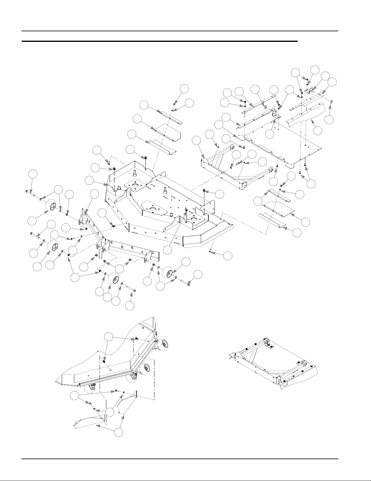
54" Rear Discharge Deck Assy–S/N Prior to 08010000
1
2
26
3
22
5
6
6
8
8
9
5
11
5
10
12
12
12
12
13
13
13
13
14
14
15
15
15
16
16
16
16
7
7
7
7
23
23
26
3
24
25
21
21
20
20
25
18
17
19
19
24
26
3
10
25
13
13
14
10
5
DEFLECTOR DETAIL
27
4
5
4
22
28
28
7-22 108602 10/08
Page 91

54" Rear Discharge Deck Assy–S/N Prior to 08010000
2
1
ITEM
NO.
10 036244 036244 20 CS .375-16 X 1.00 HX G5 ZN
11 107975 107975 1 54" REAR DISCHARGE FRONT ANGLE
12 781708 N/A 4 CS .500-13 X 4.25 HX G5 ZN
13 767962 N/A 8 FW .531 X 1.063 X.090 SAE HD ZN
14 053199 N/A 4 NT .500-13 HX JAM ZN
15 781567 781567 4 NT .50-13 HXZY NL
16 031997 N/A 4 ANTI-SCALP WHEEL
17 106724 106724 1 RD DEFLECTOR CLAMP LS ANGLE
18 106666 106666 1 RD D EFLECTOR CLAMP RS ANGLE
19 601113 601113 2 RD SIDE FLAP
20 107972 107972 2 ANGLE RD DISCHARGE FLAP
21 601017 601017 2 RD REAR FLAP
22 107973 107973 2 ANGLE DECK STIF FENER
23 106591 106591 2 RD DECK GUARD BRACKET
24 778399 778399 2 FW .781 X 1.375 X .250 ZNYC
25 016253 016253 12 CB .312-18 X .750 FUL ZN
26 058776 058776 12 NT .312-18 HXZY NL
27 107978 107978 2 AIR FLOW BAFFLE
28 600994 600994 14 RIVET NUT, 3/8-16 THREAD
SERVICE
PART NO.
1 548644 107933 1 54" REAR DISCHARGE DECK W/A
2 108066 108066 1 RD DECK GUARD
3 768523 768523 12 FW .343 X .687 X .051/.080 HD ZN
4 086660 086660 6 NT .375-16 HX LK NY
5 767954 767954 26 FW .406 X .812 X .060 SAE HD ZN
6 025395 025395 12 CB .375-16 X 1.00 STD CD
7 601069 601069 4 CN .312-18X.200 MAX THK
8 015495 015495 2 STRAIGHT GREASE FITTING
9 349803 349803 1 PUSHER
788166 788166 4 ANTI SCALP WHEEL ASSEMBLY
MFG.
PART NO.
QTY. DESCRIPTION
NOTES:
1. Includes Items 12 through 14 and 16.
2. Service part deck includes decals, see ‘‘54" Rear Discharge Deck
Decals’’ on page 9-7.
108602 10/08 7-23
Page 92

54" Rear Discharge Deck Pulley Assy—S/N 08100000 &
1
1
10
13
12
9
18
15
11
20
4
2
8
14
22
22
22
19
20
21
19
26
10
27
29
28
32
23
33
24
24
2
3
30
23
23
22
19
10
25
3
1
23
5
6
21
5
17
5
19
27
16
2
31
18
5
11
6
5
6
7
Higher
7-24 108602 10/08
Page 93

54" Rear Discharge Deck Pulley Assy—S/N 08100000 &
4
5
Higher
ITEM
NO.
1 601015 601015 1 54" REAR DISCHARGE DECK BELT
2 110449 110449 1 RIGHT 54" REAR DISCHARGE PULLEY COVER
3 110448 110448 1 LEFT 54" REAR DISCHARGE PULLEY COVER
4 794446 794446 1 CS .625-11 X 1.500 HX G5
5 028118 028118 7 FW .62 X 1.00 X .134 ZN
6 796714 796714 5 6" HB IDLER PULLEY RD
7 600296 600296 1 DECK IDLER SPACER
8 109948 109948 1 IDLER ARM W/A
9 781567 781567 1 NT .500-13 HX G8 ZY NL
10 767962 767962 13 FW .531 X 1.063 X .090 SAE HD ZN
11 770867 770867 2 PLASTIC BUSHING .750X1(FS)
12 109549 109549 1 IDLER PIVOT BUSHING
13 781302 781302 1 IDLER SPRING
14 259812 259812 1 CHAIN DECK LIFT SPRING
15 704759 704759 1 FW .500X 1.250X.075 ZNY
16 601779 601779 1 IDLER GUIDE UHMW
17 797910 797910 2 CS .312-18X1.50FLT SH ZY
18 016972 016972 4 NT .625-11 HX G5 ZNYC
19 016527 016527 15 CS .500-13 X 1.00 HX G5 ZN
20 752386 752386 3 CW .515X 2.25X .204 ZN
21 798967 798967 3 B-SECTION PULLEY 5.44 EOD
22 792002 792002 4 5/16-18 X 3/4" MALE KNOB
23 782474 782474 5 CW .631 X 2.250 X .187 PNT
24 783738 783738 2 CS .625-11X3.00 FULL HX G5 ZN
25 796680X 796680 1 REAR DISCHARGE DECK SPINDLE ASSEMBLY
26 796235X 796235 2 DECK SPINDLE ASSY
27 212472 212472 3 KEY 1/4 SQ X 1.00 LONG
28 601013 601013 1 BLADE, F18.50-L-F-CCW
29 601012 601012 2 BLADE F18.50"-L-F-CW
30 796722 796722 1 CS .625-11 X 3.00 LH HX G
31 768523 768523 1 FW .343 X .687 X .051/.080 HD ZN
32 058776 058776 1 NT .312-18 HXZY NL
33 029934 029934 2 CS .625-11 X 3.00 HX G5 ZNYC
SERVICE
PART NO.
MFG.
PART NO.
QTY. DESCRIPTION
NOTES:
1. Torque to 118 ft. lbs.
2. Torque to 65-75 ft. lbs.
3. See ‘‘54" Rear Discharge Deck Belt Routing and Tensioning’’ on page
8-6 for belt tensioning.
4. See ‘‘Spindle Assembly–796680’’ on page 7-29 for breakdown.
5. See ‘‘Spindle Assembly–796235’’ on page 7-28 for breakdown.
108602 10/08 7-25
Page 94

54" Rear Discharge Deck Pulley Assy—S/N Prior to 08100000
1
1
5
2
5
6
4
4
7
15
8
9
10
12
13
13
13
13
14
15
16
14
18
17
20
21
22
23
23
24
27
27
2
3
28
23
26
25
14
17
19
3
1
23
5
7
16
5
7
5
14
20
11
4
5
7
2
7-26 108602 10/08
Page 95

54" Rear Discharge Deck Pulley Assy—S/N Prior to 08100000
4
5
ITEM
NO.
1 601015 601015 1 54" REAR DISCHARGE DECK BELT
2 107945 107945 1 RIGHT 54" REAR DISCHARGE PULLEY COVER
3 107946 107946 1 LEFT 54" REAR DISCHARGE PULLEY COVER
4 016972 016972 4 NT .625-11 HX G5 ZNYC
5 028118 028118 7 FW .62 X 1.00 X .134 ZN
6 794446 794446 1 CS .625-11 X 1.500 HX G5
7 796714 796714 5 6" HB IDLER PULLEY RD
8 781302 781302 1 IDLER SPRING
9 373191 059931 1 SIDE MOUNT CHAIN (21 LINKS)
10 797910 797910 6 CS .312-18 X 1.250 FLT SH ZNYC
11 601434 601434 2 UHMW IDLER SLIDE
12 350884 350884 1 REAR DISCHARGE DECK IDLER
13 792002 792002 4 5/16-18 X 3/4" MALE KNOB
14 016527 016527 15 CS .500-13 X 1.00 HX G5 ZN
15 752386 752386 3 FW .510 X 1.75 X .18 ZN
16 798967 798967 3 B-SECTION 6.10 PULLEY
17 767962 767962 12 FW .531 X 1.063 X .090 SAE HD ZN
18 796235X 796235 2 DECK SPINDLE ASSY
19 796680X 796680 1 REAR DISCHARGE DECK SPINDLE ASSEMBLY
20 212472 212472 3 KEY 1/4 SQ X 1.00 LONG
21 601012 601012 2 BLADE F18.50"-L-F-CW
22 601013 601013 1 BLADE, F18.50-L-F-CCW
23 782474 782474 5 CW .631 X 2.250 X .187 PNT
24 029934 029934 2 CS .625-11 X 3.00 HX G5 ZNYC
25 768523 768523 4 FW .343 X .687 X .051/.080 HD ZN
26 058776 058776 4 NT .312-18 HXZY NL
27 783738 783738 2 CS .625-11X3.00 FULL HX G5 ZN
28 796722 796722 1 CS .625-11 X 3.00 LH HX G
SERVICE
PART NO.
MFG.
PART NO.
QTY. DESCRIPTION
NOTES:
1. Torque to 118 ft. lbs.
2. Torque to 65-75 ft. lbs.
3. See ‘‘54" Rear Discharge Deck Belt Routing and Tensioning’’ on page
8-6 for belt tensioning.
4. See ‘‘Spindle Assembly–796235’’ on page 7-28 for breakdown.
5. See ‘‘Spindle Assembly–796680’’ on page 7-29 for breakdown.
6. Item 11 (601434) replaces idler slide components 600171, 600189, and
786335 found on tractors with serial numbers prior to 08010000.
108602 10/08 7-27
Page 96

Spindle Assembly–796235
1
2
1
6
2
3
4
1
5
ITEM
NO.
1 077123 N/A 2 BEARING W/O COLLAR
2 766204 N/A 1 BLADE SPINDLE BUSHING
3 034843 N/A 1 CAST SPINDLE HOUSING
4 012005 N/A 1 GREASE FITTING
5 600893 N/A 1 BEARING DUST COVER
6 796227 N/A 1 SADDLELESS SPINDLE SHAFT
SERVICE
PART NO.
MFG.
PART NO.
QTY. DESCRIPTION
NOTES:
1. Install upper bearing with extended inner race up.
2. Install lower bearing with extended inner race down.
3. Apply grease to zerk.
7-28 108602 10/08
Page 97

Spindle Assembly–796680
1
2
1
6
2
3
4
1
5
ITEM
NO.
1 077123 N/A 2 BEARING W/O COLLAR
2 766204 N/A 1 BLADE SPINDLE BUSHING
3 034843 N/A 1 CAST SPINDLE HOUSING
4 012005 N/A 1 GREASE FITTING
5 600893 N/A 1 BEARING DUST COVER
6 796698 N/A 1 SPINDLE SHAFT
SERVICE
PART NO.
MFG.
PART NO.
QTY. DESCRIPTION
NOTES:
1. Install upper bearing with extended inner race up.
2. Install lower bearing with extended inner race down.
3. Apply grease to zerk.
108602 10/08 7-29
Page 98

7-30 108602 10/08
Page 99

Chapter 8 Contents
Deck Installation . . . . . . . . . . . . . . . . . . . . . . . . . . . . . . . . . . . . . . . . 8-2
66" & 54" Side Discharge Deck Belt Routing and Tensioning. . . . . . 8-4
60" Side Discharge Deck Belt Routing and Tensioning. . . . . . . . . . . 8-5
54" Rear Discharge Deck Belt Routing and Tensioning . . . . . . . . . . 8-6
Seat Installation—S/N 08010000 & Higher . . . . . . . . . . . . . . . . . . . . 8-8
Seat Installation—S/N Prior to 08010000 . . . . . . . . . . . . . . . . . . . . 8-10
ROPS Installation . . . . . . . . . . . . . . . . . . . . . . . . . . . . . . . . . . . . . . 8-12
108602 10/08 8-1
Page 100

Deck Installation
TRACTOR
ASSEMBLY
DECK
ASSEMBLY
1
2
3
4
5
5
8-2 108602 10/08
 Loading...