

Page 1

Hustler Diesel Z
Parts Manual
•••••••
Hustler Turf Equipment
•••••
P.O. Box 7000
•••
Hesston, Kansas
•
67062-2097
Page 2
IMPOR TANT: This engine is not equipped with a spark arrester muffler. It is a violation o f California Public Resource Code
Section 444 2 t o use o r operate t his engine on any forest-cover e d, brush-covered, or grass-covered unimprove d land. Othe r
states or federal areas may have similar laws.
Th is spark ignition syst em complies with Canadi an ICES-002.
The Eng ine Owner’s Manual provides information re garding the U. S. Environmental Protection Agency (EPA) and the
California Emission Control Regulation of emission systems, maintenance and warranty.
Keep E n gine Owne r’ s Manual with your unit. S h ould the Engine Owner’s Manual become da mage d o r i l l egible, repla ce i mmediate l y . Repla c ements may be or dered per the informat ion f ound in t he Pro du ct Inf ormation sect ion of t h e
owner’s manual .
The engine exhaust from this product
cont ains che mic als k no wn to the S tat e
of California to cause cancer , birth
defects or other reproductive harm.
WARNING:
t-2 109706 10/08
Page 3

Chapter 1
Chapter 2
Chapter 3
Chapter 4
Chapter 5
Table of Contents
General Information . . . . . . . . . . . . . . . . . . . . . . . . . . . . . . . . . . . . 1-1
Footrest Assembly . . . . . . . . . . . . . . . . . . . . . . . . . . . . . . . . . . . . . 2-2
Rivet Nut Installation. . . . . . . . . . . . . . . . . . . . . . . . . . . . . . . . . . . . 2-4
Hydraulic Component Fittings. . . . . . . . . . . . . . . . . . . . . . . . . . . . . 3-2
Hydraulic Component Mounting . . . . . . . . . . . . . . . . . . . . . . . . . . . 3-4
Hydraulic Line Connections . . . . . . . . . . . . . . . . . . . . . . . . . . . . . . 3-6
Deck Lift Assembly . . . . . . . . . . . . . . . . . . . . . . . . . . . . . . . . . . . . . 4-2
Steering Sub-Assembly. . . . . . . . . . . . . . . . . . . . . . . . . . . . . . . . . . 4-4
Steering System . . . . . . . . . . . . . . . . . . . . . . . . . . . . . . . . . . . . . . . 4-6
Brake System . . . . . . . . . . . . . . . . . . . . . . . . . . . . . . . . . . . . . . . . . 4-8
Engine Sub-Assembly. . . . . . . . . . . . . . . . . . . . . . . . . . . . . . . . . . . 5-2
Belt Drive System . . . . . . . . . . . . . . . . . . . . . . . . . . . . . . . . . . . . . . 5-6
Firewall & ROPS Assembly. . . . . . . . . . . . . . . . . . . . . . . . . . . . . . . 5-10
Air Filter Installation. . . . . . . . . . . . . . . . . . . . . . . . . . . . . . . . . . . . . 5-12
Cooling System Installation. . . . . . . . . . . . . . . . . . . . . . . . . . . . . . . 5-14
Engine Cover Installation . . . . . . . . . . . . . . . . . . . . . . . . . . . . . . . . 5-16
Fuel System . . . . . . . . . . . . . . . . . . . . . . . . . . . . . . . . . . . . . . . . . . 5-18
Battery and Electrical Connections. . . . . . . . . . . . . . . . . . . . . . . . . 5-20
Instrument Panel. . . . . . . . . . . . . . . . . . . . . . . . . . . . . . . . . . . . . . . 5-22
Electrical Schematic—601367 . . . . . . . . . . . . . . . . . . . . . . . . . . . . 5-24
Chapter 6
Front Wheel Assembly . . . . . . . . . . . . . . . . . . . . . . . . . . . . . . . . . . 6-2
Front Wheel Breakdown—747782 . . . . . . . . . . . . . . . . . . . . . . . . . 6-4
Optional Semi-Pneumatic Tire/Wheel—789537 . . . . . . . . . . . . . . . 6-5
Drive Wheel Assembly Installation . . . . . . . . . . . . . . . . . . . . . . . . . 6-6
Anti-Rollover Wheel Assembly . . . . . . . . . . . . . . . . . . . . . . . . . . . . 6-7
Chapter 7
72" Side Discharge XR7 Deck Assembly . . . . . . . . . . . . . . . . . . . . 7-2
72" Side Discharge XR7 Deck Pulley Assembly. . . . . . . . . . . . . . . 7-4
66" Side Discharge XR7 Deck Assembly . . . . . . . . . . . . . . . . . . . . 7-6
66" Side Discharge XR7 Deck Pulley Assembly. . . . . . . . . . . . . . . 7-8
60" Side Discharge XR7 Deck Assembly . . . . . . . . . . . . . . . . . . . . 7-10
60" Side Discharge XR7 Deck Pulley Assembly. . . . . . . . . . . . . . . 7-12
54" Side Discharge XR7 Deck Assembly . . . . . . . . . . . . . . . . . . . . 7-14
54" Side Discharge XR7 Deck Pulley Assembly. . . . . . . . . . . . . . . 7-16
Side Discharge Deck—"A" Adaptors. . . . . . . . . . . . . . . . . . . . . . . . 7-18
Side Discharge Deck—"B" Adaptors. . . . . . . . . . . . . . . . . . . . . . . . 7-20
72" Rear Discharge Deck Assembly. . . . . . . . . . . . . . . . . . . . . . . . 7-22
109706 10/08 c-1
Page 4

Chapter 8
Chapter 9
72" Rear Discharge Deck Pulley Assembly . . . . . . . . . . . . . . . . . . 7-24
60" Rear Discharge Deck Assembly . . . . . . . . . . . . . . . . . . . . . . . 7-26
60" Rear Discharge Deck Pulley Assembly . . . . . . . . . . . . . . . . . . 7-28
54" Rear Discharge Deck Assembly . . . . . . . . . . . . . . . . . . . . . . . 7-30
54" Rear Discharge Deck Pulley Assembly . . . . . . . . . . . . . . . . . . 7-32
Spindle Assembly—796235X. . . . . . . . . . . . . . . . . . . . . . . . . . . . . 7-34
Spindle Assembly—796680X. . . . . . . . . . . . . . . . . . . . . . . . . . . . . 7-35
Deck Installation. . . . . . . . . . . . . . . . . . . . . . . . . . . . . . . . . . . . . . . 8-2
Seat Installation . . . . . . . . . . . . . . . . . . . . . . . . . . . . . . . . . . . . . . . 8-4
72", 66" & 54" Side Disch. Deck Belt Routing/Tensioning . . . . . . . 8-6
60" Side Disch. XR7 Deck Belt Routing/Tensioning. . . . . . . . . . . . 8-7
72", 60" & 54" Rear Discharge Deck Belt Routing/Tensioning. . . . 8-8
Tractor Decals . . . . . . . . . . . . . . . . . . . . . . . . . . . . . . . . . . . . . . . . 9-2
72" Side Discharge XR7 Deck Decals . . . . . . . . . . . . . . . . . . . . . . 9-4
66" Side Discharge XR7 Deck Decals . . . . . . . . . . . . . . . . . . . . . . 9-5
60" Side Discharge XR7 Deck Decals . . . . . . . . . . . . . . . . . . . . . . 9-6
54" Side Discharge XR7 Deck Decals . . . . . . . . . . . . . . . . . . . . . . 9-7
72" Rear Discharge Deck Decals. . . . . . . . . . . . . . . . . . . . . . . . . . 9-8
60" Rear Discharge Deck Decals. . . . . . . . . . . . . . . . . . . . . . . . . . 9-9
54" Rear Discharge Deck Decals. . . . . . . . . . . . . . . . . . . . . . . . . . 9-10
Chapter 10
Assembly Pictures and Aids. . . . . . . . . . . . . . . . . . . . . . . . . . . . . . 10-3
Maintenance & Adjustment Safety . . . . . . . . . . . . . . . . . . . . . . . . . 10-10
Maintenance. . . . . . . . . . . . . . . . . . . . . . . . . . . . . . . . . . . . . . . . . . 10-14
Adjustment . . . . . . . . . . . . . . . . . . . . . . . . . . . . . . . . . . . . . . . . . . . 10-30
Index. . . . . . . . . . . . . . . . . . . . . . . . . . . . . . . . . . . . . . . . . . . . . . . . . . . . . . . . i-1
c-2 109706 10/08
Page 5

Chapter 1
General Information
This Manual covers Hustler Diesel Z models 928606A/B, 928614A/B, 928622A/B, 928630A/B,
928648, 928655 & 928663.
Frequently Ordered Parts
PART NO. DESCRIPTION
601413X Hydraulic Oil Filter Element
601424 Pump Drive Belt 48.50 PVL X 4
601531 Deck Belt B-Sec 235" EL (72" Side Disch. Deck)
601528 Deck Belt B-Sec 224" EL (66" Side Disch. Deck)
601466 Deck Belt B-Sec 216" EL (60" Side Disch. Deck)
601525 Deck Belt B-Sec 201" EL (54" Side Disch. Deck)
601692 Deck Belt BB-Sec 268" EL (72" Rear Disch. Deck)
601673 Deck Belt BB-Sec 251.4" EL (60" Rear Disch. Deck)
601691 Deck Belt BB-Sec 240.8" EL (54" Rear Disch. Deck)
798702 Blade, F24.50"-H-F-CW
798496 Blade, F22.50"-H-F-CW
794685 Blade, F20.50" H-F-CW
797696 Blade, F18.50"-H-F-CW
796839 Blade, F23.86"-L-F-CW
796508 Blade, F23.86"-L-F-CCW
600901 Blade, F20.50" L-F-CW
795633 Blade, F20.50" L-F-CCW
601012 Blade, F18.50" L-F-CW
601013 Blade, F18.50" L-F-CCW
130366120 Fuel Spin On Filter
785261 Main Air Filter Element
785279 Safety Air Filter Element
140517020 Engine Oil Filter
Service Literature
PART NO. DESCRIPTION
601656 Owner’s Manual
109821 Engine Manual Shibaura Diesel
Note: When ordering parts, yo u must use the part number as shown for each part, not the index number . Always give
the model and serial number to your parts and service represen tative.
Note: Items sold in bulk such as seals and hoses are sold by the foot.
109706 10/08 1-1
Page 6

Using this manual
Illustrations used were current at the time of printing, but subsequent production changes may cause your machine to
vary slightly in detail. Excel Industries, Inc. reserves the right to redesign and change the machine as deemed nece ssary, without notification. If a change has been made to your machine which is not reflected in this parts manual, see
your Hustler dealer for current information and parts.
Hardware Description Codes & Abbreviations
The following codes are used throughout this parts manual. Refer to this list when ordering parts.
ABBREVIATION DESCRIPTION
CB Carriage Bolt
CE Clevis Pin
CP Cotter Pin
CS Cap Screw
CW Cup Washer
FDRW Fender Washer
FW Flat Washer
HX Hex Head
LW Lock Washer
MB Machine Bushing
MS Machine Screw
NT Nut
SC Self Tapping Cap Screw
SH Socket Head
SB Shoulder Bolt
SS Set Screw
OD Outside Diameter
ID Inside Diameter
Standard Torques
The following chart lists the standard torque va lues for the threaded fasteners found in this manual. Torque all cap
screws, nuts and set screws to these values unless a different torque is shown in the Notes se ction next to the fastener .
SIZE FT-LBS NM SIZE FT-LBS NM
.250 8.2 11.1 M3 1 1.3
.312 17 23 M4 2.2 3
.375 30 40 M5 4.5 6.1
.438 48 65 M6 7.7 10.4
.500 73 99 M8 18.5 25
.562 105 143 M10 37 50
.625 145 200 M12 64 87
.750 260 350 M14 80 108.5
.875 420 565 M16 160 215
1.00 625 850 M20 320 435
M24 555 750
NOTE:
Loctite® 592 to be used on all pipe threads.
Lubricate all grease zerks.
1-2 109706 10/08
Page 7

Chapter 2 Contents
Footrest Assembly. . . . . . . . . . . . . . . . . . . . . . . . . . . . . . . . . . . . . . . 2-2
Rivet Nut Installation . . . . . . . . . . . . . . . . . . . . . . . . . . . . . . . . . . . . . 2-4
109706 10/08 2-1
Page 8

Footrest Assembly
5
6
3
4
4
7
7
7
9
4
10
4
11
1
8
3
4
2
1
2-2 109706 10/08
Page 9

Footrest Assembly
2
INDEX NO.
1 785485 785485 2 UPPER STEP TREAD 5.00
2 785493 785493 2 LOWER STEP TREAD 9.00
3 056069 056069 2 CS .375-16X .625 HX G5
4 767954 767954 8 FW .406X .812 X.060 SAE
5 549410 109104 1 FLOOR PLATE HDZ
6 601571 601571 2 VIBRATION MOUNT
7 781880 781880 4 BUMPER .500X 1.00X .31
8 109399 109399 1 FLOOR PAN MOUNT STRAP
9 086660 086660 4 NT .375-16 HXZY NL
10 054502 054502 2 NT .375-16 HX GRD 5 ZNY
11 052860 052860 2 CS .375-16X1.250 HX G5
SERVICE
PART NO.
MFG. PART
NO.
QTY. DESCRIPTION
NOTES:
1. Do not tighten, Item 5 (109104 Floor Plate) must be able to pivot on
these bolts.
2. Service part includes Items 1 and 2 (step treads).
109706 10/08 2-3
Page 10
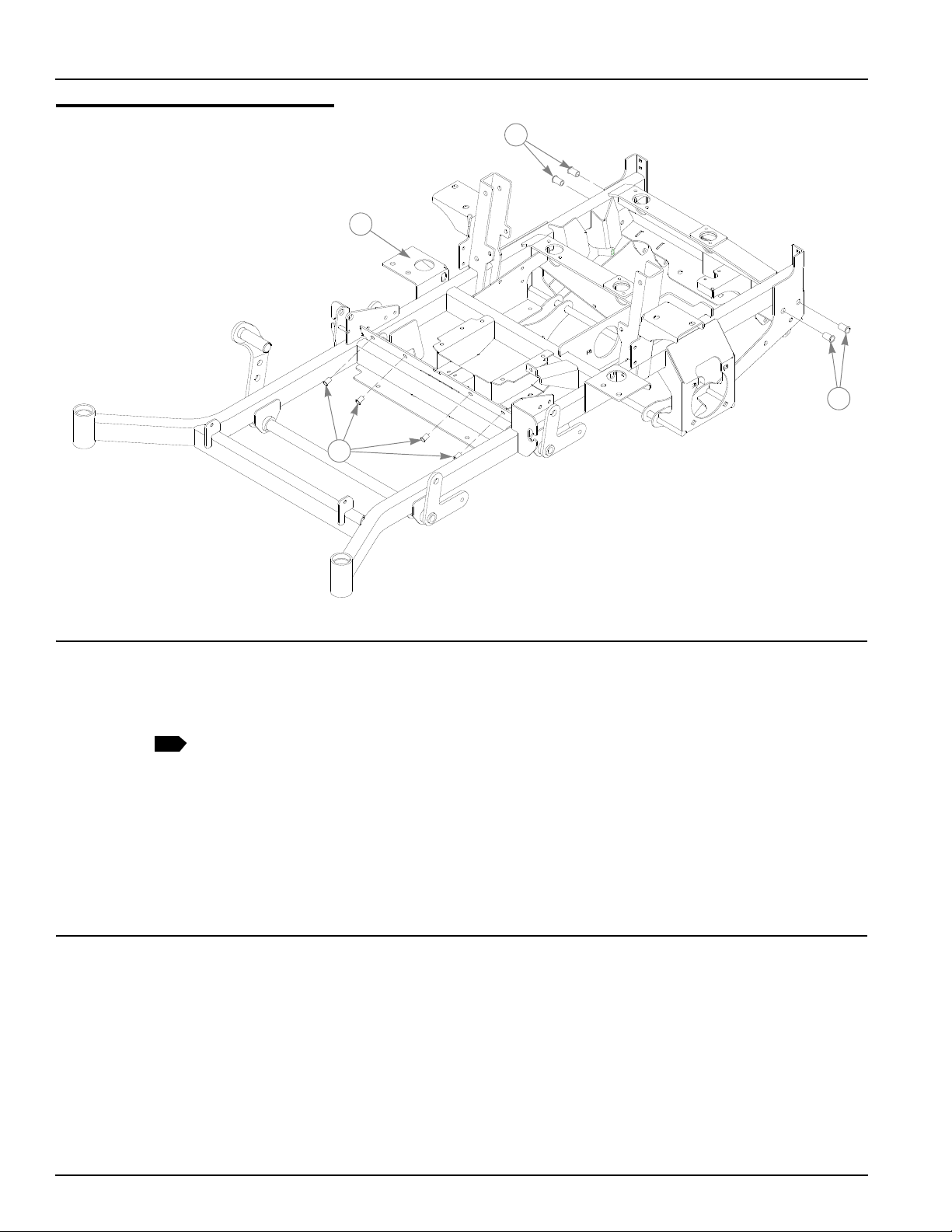
Rivet Nut Installation
1
2
3
3
1
INDEX NO.
1 549139 109624 1 TRACTOR FRAME (72" SIDE DISCHARGE)
2 808493 808493 4 3/8-16 THREAD RIVET NUT
3 600961 600961 4 1/2-13 THREAD RIVET NUT
SERVICE
PART NO.
549121 109621 1 TRACTOR FRAME (66" SIDE DISCHARGE)
549113 108932 1 TRACTOR FRAME (60" SIDE DISCHARGE)
549105 109617 1 TRACTOR FRAME (54" SIDE DISCHARGE)
549758 110626 1 TRACTOR FRAME (72" REAR DISCHARGE)
549618 110623 1 TRACTOR FRAME (60" REAR DISCHARGE)
549766 110628 1 TRACTOR FRAME (54" REAR DISCHARGE)
MFG. PART
NO.
QTY. DESCRIPTION
NOTES:
1. Service part includes Items 2 and 3 and decals. See “Tractor Decals” on
page 9-2.
2-4 109706 10/08
Page 11

Chapter 3 Contents
Hydraulic Component Fittings . . . . . . . . . . . . . . . . . . . . . . . . . . . . . . 3-2
Hydraulic Component Mounting . . . . . . . . . . . . . . . . . . . . . . . . . . . . 3-4
Hydraulic Line Connections. . . . . . . . . . . . . . . . . . . . . . . . . . . . . . . . 3-6
109706 10/08 3-1
Page 12
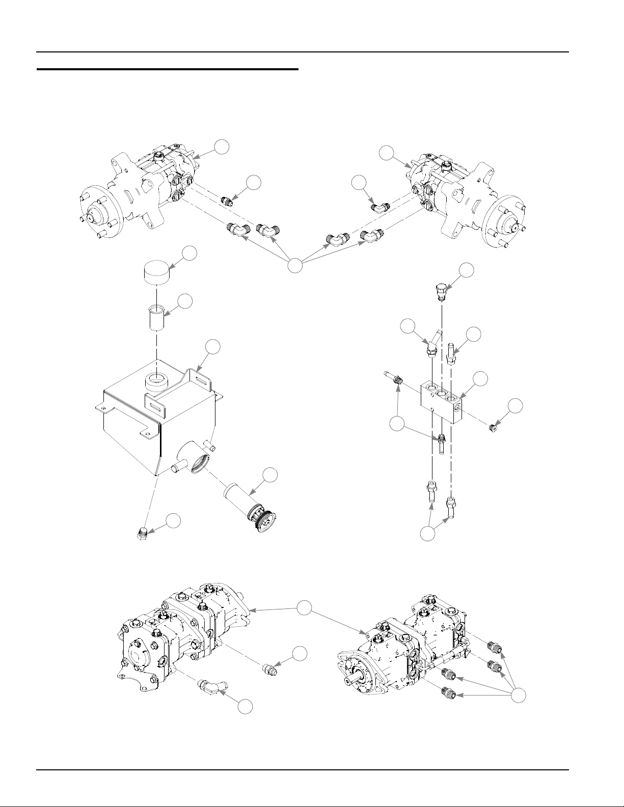
Hydraulic Component Fittings
7
4
3
9 10
2
1
6
5
8
11
12
13
15
14
16
13
20
17
18
19
3-2 109706 10/08
Page 13

Hydraulic Component Fittings
2
INDEX NO.
1 601556 601556 1 WHEEL MOTOR RH
2 601557 601557 1 WHEEL MOTOR LH
3 032763 032763 1 BREATHER CAP
4 032771 032771 1 STRAINER
5 549345 109366 1 RESERVOIR W/A HDZ
6 601413X 601413 1 FILTER ELEMENT
7 781658 N/A 1 FITTING STR-8MORB/HEX
8 781542 N/A 4 FITTING 90-8MORB/-8MSL
9 779132 N/A 1 FITTING STR-6MORB/-6JI
10 795922 N/A 1 FITTING 90-6MORB/-6MJI
11 601568 N/A 1 VALVE CARTRIDGE CHECK
12 601592 N/A 1 FITTING -8MORB/-8BEAD
13 601523 N/A 3 FITTING -8MORB/-8 BEAD
14 601569 N/A 1 FITTING PLUG -8MORB/HEX
15 601476 N/A 1 MANIFOLD CASE DRAIN
16 787473 N/A 2 FITTING -6MORB/-6 BEAD
17 771337 N/A 1 FITTING STR-8MORB/-8MJ
18 601524 N/A 1 FITTING -8MORB/-12 BEAD
19 781534 N/A 4 FITTING STR-8MORB/-8MS
20 601318 601318 1 PUMP HG TANDEM 21
SERVICE
PART NO.
N/A 601498 1 HYDRO KIT HDZ (INCLUDES 7-19)
MFG. PART
NO.
QTY. DESCRIPTION
NOTES:
1. Hydraulic system capacity is 7 US quarts. Fill reservoir to within 1" of top
of Item 4 (032771 Strainer).
2. Service part includes safety decal 779280. See “T ractor Decals” on
page 9-2.
109706 10/08 3-3
Page 14
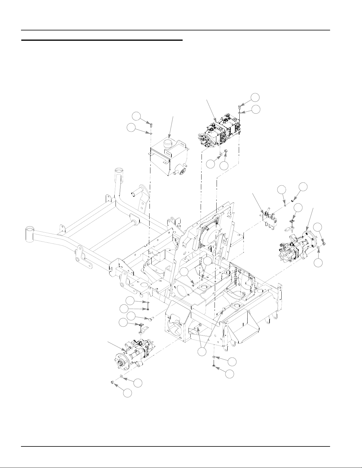
Hydraulic Component Mounting
7
4
7
3
2
1
5
6
2
6
5
2
8
9
4
11
10
6
5
LEFT WHEEL
MOTOR
RIGHT
WHEEL
MOTOR
MANIFOLD
TANDEM PUMPS
RESERVOIR
12
12
2
3-4 109706 10/08
Page 15

Hydraulic Component Mounting
1
INDEX NO.
1 036236 036236 4 CS .312-18X1.000 HX G5
2 768523 768523 12 FW .343X.687X.051/.080H
3 036244 036244 2 CS .375-16X1.000 HX G5
4 767954 767954 4 FW .406X .812 X.060 SAE
5 767962 767962 10 FW .531X 1.063X.090 SAE
6 008193 008193 10 NT .500-13 HX G5 ZNYC
7 034272 034272 6 NT .312-18 HX G5 ZNYC
8 064345 064345 2 CS .312-18X2.000 HX G5
9 028274 028274 2 CB .500-13X 1.500 FULL
10 601427 601427 8 CB .500-13 X 2.500 G5 ZN
11 054502 054502 2 NT .375-16 HX GRD 5 ZNY
12 601247 N/A 2 BRAKE ARM RETAINING CLIP
SERVICE
PART NO.
MFG. PART
NO.
QTY. DESCRIPTION
NOTES:
1. Part of wheel motors (601556 and 601557).
109706 10/08 3-5
Page 16
Hydraulic Line Connections
14
4
3
11
2
16
1
13
15
5
5
4
3
3
1
2
6
7
8
8
7
12
11
10
10
9
9
3
3
LEFT WHEEL
MOTOR
RIGHT
WHEEL
MOTOR
MANIFOLD
TANDEM PUMPS
RESERVOIR
RIGHT
WHEEL
MOTOR
LEFT WHEEL
MOTOR
TANDEM PUMPS
FIREWALL &
OIL COOLER
3-6 109706 10/08
Page 17

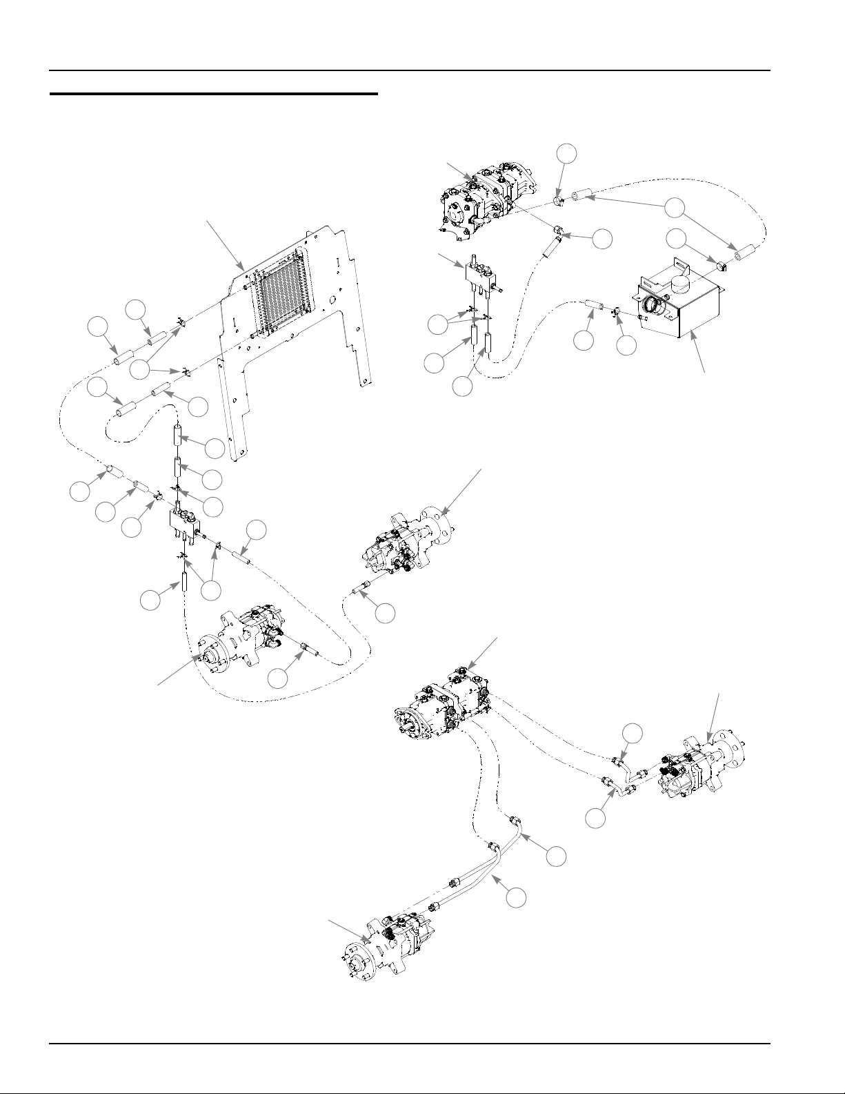
Hydraulic Line Connections
INDEX NO.
1 601521 N/A 1 HOSE MANIFOLD BLOCK TO OIL COOLER
2 601583 N/A 1 HOSE MANIFOLD BLOCK
3 601001 601001 7 SPRING CLAMP .75" DIA
4 601522 N/A 1 HOSE RETURN COOLER TO MANIFOLD BLOCK
5 601584 N/A 1 HOSE MANIFOLD BLOCK
6 601617 601617 2 SPRING CLAMP 5/8" DIA.
7 601519 N/A 1 HOSE CASE DRAIN LEFT MOTOR
8 601518 N/A 1 HOSE CASE DRAIN RIGHT MOTOR
9 601570 N/A 1 HOSE RETURN MANIFOLD BLOCK TO RESERVOIR
10 601520 N/A 1 HOSE CASE DRAIN PUMP TO MANIFOLD
11 700484 700484 2 CLAMP HOSE (FS)
12 601517 N/A 1 HOSE SUCTION HDZ HYDRO
13 601494 N/A 1 TUBE TP-TM RT LOOP
14 601495 N/A 1 TUBE BP-BM RT LOOP
15 601496 N/A 1 TUBE TP-TM LT LOOP
16 601497 N/A 1 TUBE BP-BM LT LOOP
SERVICE
PART NO.
N/A 601498 1 HYDRO KIT HDZ (INCLUDES 1, 2, 4, 5,7-10, & 12-16)
MFG. PART
NO.
QTY. DESCRIPTION
NOTES:
1. See “Hydraulic routing” on page 10-8.
109706 10/08 3-7
Page 18

3-8 109706 10/08
Page 19

Chapter 4 Contents
Deck Lift Assembly . . . . . . . . . . . . . . . . . . . . . . . . . . . . . . . . . . . . . . 4-2
Steering Sub-Assembly. . . . . . . . . . . . . . . . . . . . . . . . . . . . . . . . . . . 4-4
Steering System . . . . . . . . . . . . . . . . . . . . . . . . . . . . . . . . . . . . . . . . 4-6
Brake System . . . . . . . . . . . . . . . . . . . . . . . . . . . . . . . . . . . . . . . . . . 4-8
109706 10/08 4-1
Page 20
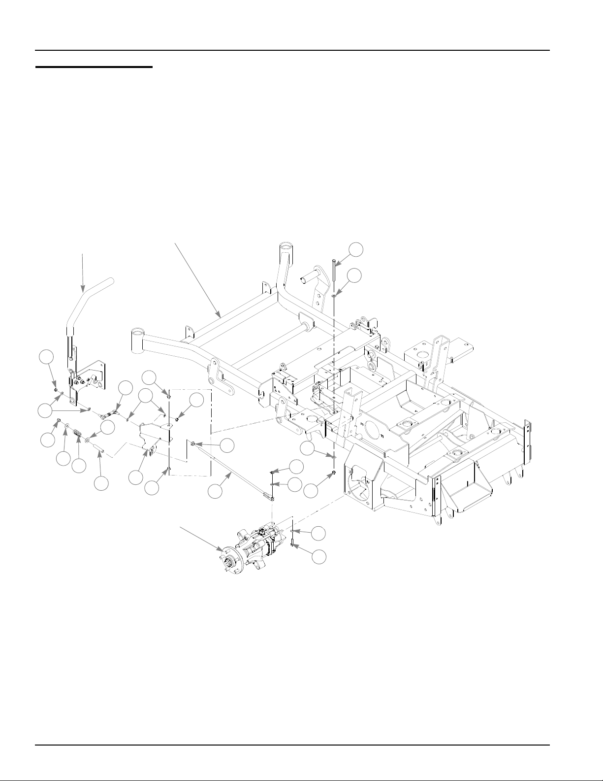
Deck Lift Assembly
TRACTOR
FRAME
1
1
1
4
1
3
2
5
5
5
5
5
4
4
5
6
8
8
4
4
4
4
14
13
9
7
10
10
4
10
11
12
8
10
9
9
6
1
4-2 109706 10/08
Page 21

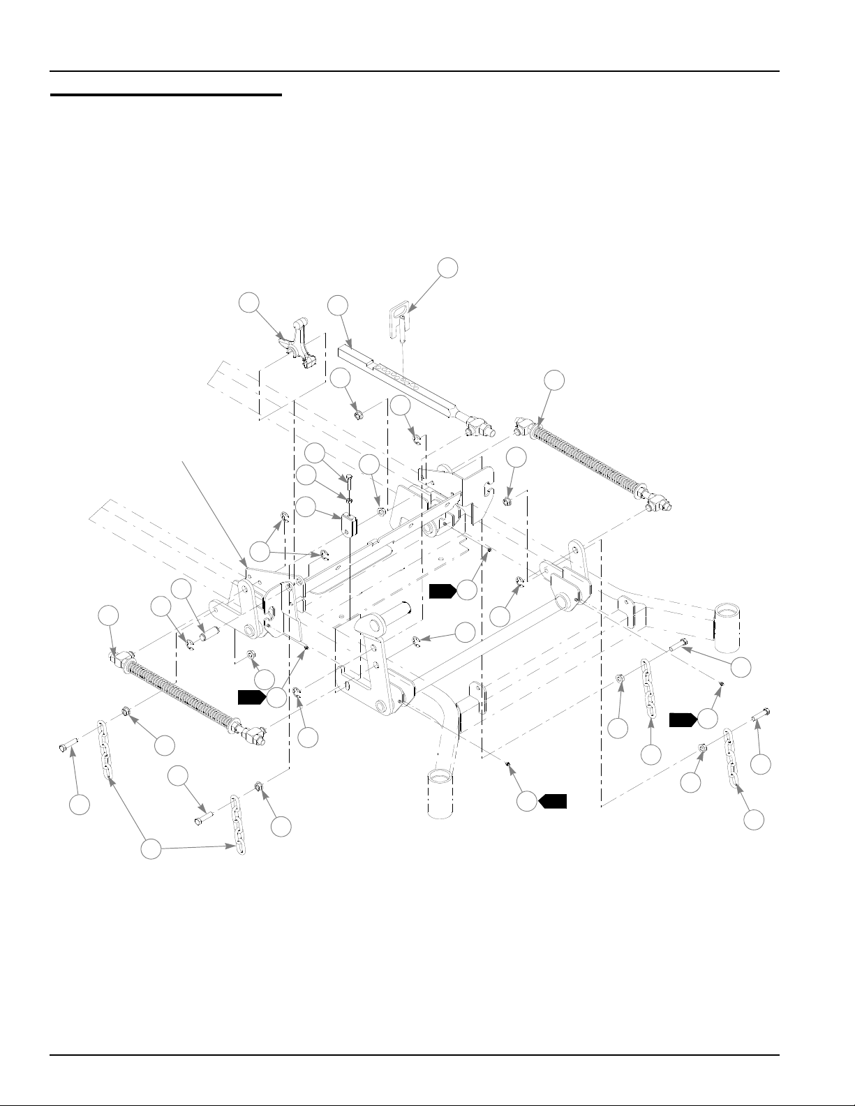
Deck Lift Assembly
ITEM
NO.
1 348318 348318 1 STOP HANDLE
2 600437 600437 1 DECK HEIGHT 1/2" PIN W/A
3 783001 783001 1 DECK LIFT INDICATOR SUBASSEMBLY
4 704643 704643 8 NT .437-14 HX FLG ZN
5 781294 781294 7 CLIP E, 1.00 X .625 X .050
6 782995 782995 2 DECK LIFT SPRING SUBASSEMBLY
7 781229 781229 1 CE .750 X 2.25 X 1.75 HEADLESS
8 055749 055749 3 CS .437-14 X 1.750 HX G5 ZN
9 348391 018846 4 DECK LIFT CHAIN
10 015495 015495 4 STRAIGHT GREASE FITTING
11 034272 034272 1 NT .312-18 HX G5 ZN
12 756270 756270 1 CS .312-18 X 1.50 FUL THR GR5 ZN
13 348458 348458 1 DECK LEVELER YOKE
14 781831 781831 1 CS .437-14 X 1.750 FUL THD G5 ZN
SERVICE
PART NO.
MFG.
PART NO.
QTY DESCRIPTION
NOTES:
1. Apply grease to zerks (see owner’s manual).
109706 10/08 4-3
Page 22
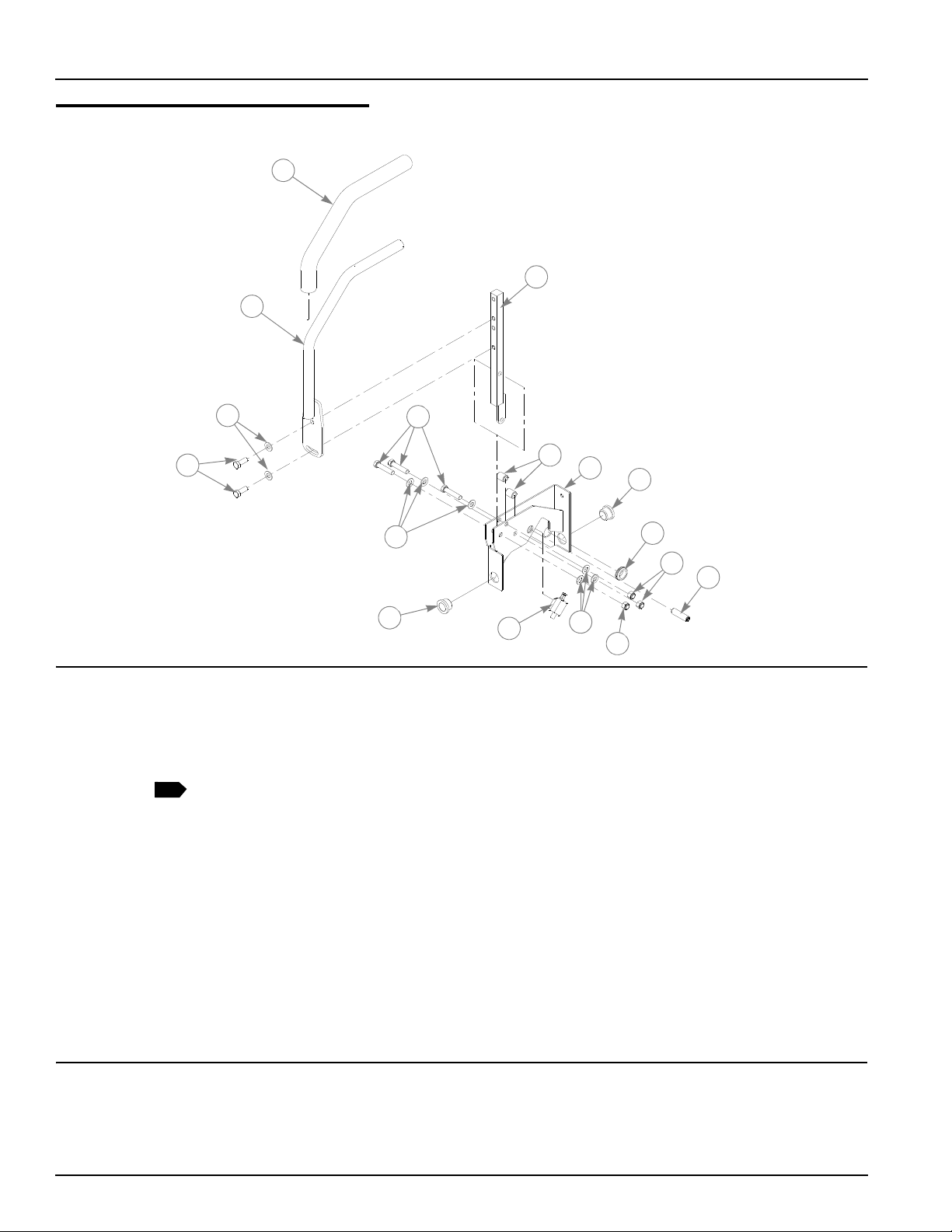
Steering Sub-Assembly
1
3
7
6
2
3
3
4
5
8
9
9
10
11
12
13
12
1
INDEX NO.
1 781260 N/A 2 STEERING BAR GRIP
2 109839 109839 2 HANDLE Z W/A
3 767954 767954 16 FW .406X .812 X.060 SAE
4 036244 036244 4 CS .375-16X1.000 HX G5
5 705178 705178 6 CS .375-16X1.750 HX G5
6 348946 348946 2 STEERING ARM MNT W/A
7 348862 348862 4 STEERLEVER BUSHING
8 109260 109260 1 STEERING BOX W/A LH
9 781153 781153 4 BUSHING UHMW
10 047456 047456 2 GM .750X.188X1.00X.12
11 781716 781716 2 SS .500-13X 1.750 SH ZNY
12 086660 086660 6 NT .375-16 HXZY NL
13 601087 601087 2 SWITCH PLUNGER
SERVICE
PART NO.
109259 109259 1 STEERING BOX W/A RH
MFG. PART
NO.
QTY. DESCRIPTION
NOTES:
1. Includes Item 1 (781260 Steering Bar Grip).
4-4 109706 10/08
Page 23

This page intentionally left blank.
109706 10/08 4-5
Page 24
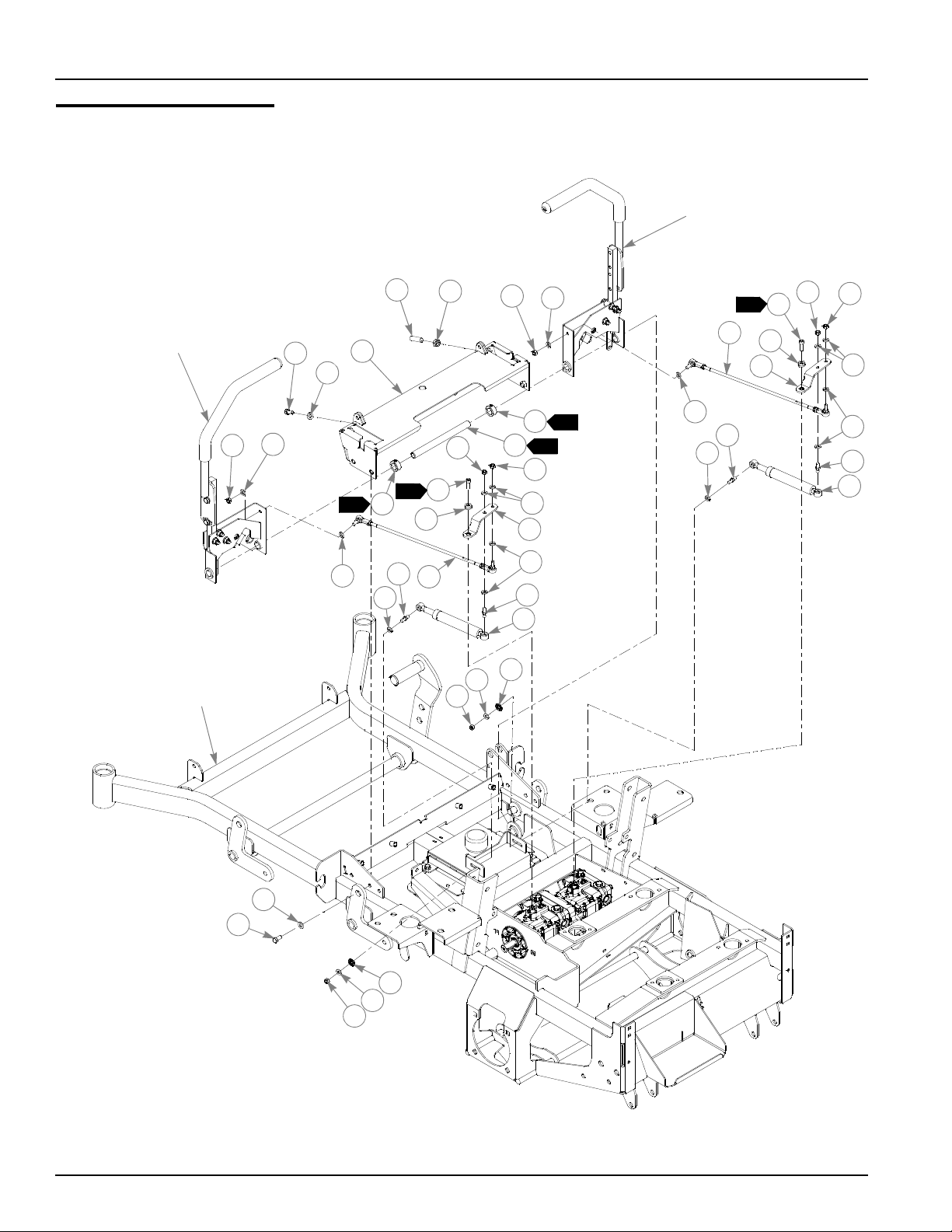
Steering System
TRACTOR
FRAME
1
1
3
2
5
5
8
7
10
4
4
9
6
7
6
8
11
12
6
6
13
6
14
15
15
6
16
6
14
10
11
6
13
12
6
15
16
15
6
17
6
12
17
6
12
7
7
2
2
3
3
See “Steering
Sub-Assembly”
on page 4-4.
See “Steering
Sub-Assembly”
on page 4-4.
4-6 109706 10/08
Page 25

Steering System
ITEM
NO.
1 348987 348987 1 STEERING CONTROL PANEL
2 781716 781716 2 SS .500-13X 1.750 SH ZNY
3 053199 053199 2 NT .500-13 HX JAM ZNYC
4 055822 055822 8 CS .375-16X .750 HX G5
5 767954 767954 8 FW .406X .812 X.060 SAE
6 768523 768523 16 FW .343X.687X.051/.080H
7 023655 023655 4 NT .312-24 HXZY NL
8 784439 784439 2 LOCK COLLAR 0.757 ID(FS)
9 108813 108813 1 STEER PIVOT TUBE
10 795377 795377 2 CS M 8-1.25X25 SH BO NY
11 795369 795369 2 RETAINER PUMP ARM HYDR
12 034272 034272 4 NT .312-18 HX G5 ZNYC
13 109118 109118 2 PUMP ARM HDZ
14 781286 781286 2 PUMP ROD ADJUSTER ASSY
15 781922 781922 4 BALL STUD DAMPER
16 600221 600221 2 STEERING DAMPER
17 029876 029876 2 LW .312 INT-EXT TOOTH Z
SERVICE
PART NO.
MFG.
PART NO.
QTY DESCRIPTION
NOTES:
1. Tube ends to be clean and free of rust. Apply thin coat of grease prior to
installing 781153 Bushing (item 9 on page 4-4).
2. Item 8 (784439 Lock Collar) to be adjusted such that 109259/109260
Steering Box (Item 8 on page 4-4) has no end play.
3. Torque to 180-200 in-lbs.
109706 10/08 4-7
Page 26
Brake System
1
TRACTOR
FRAME
1
3
2
5
6
5
4
2
10
4
15
4
7
8
9
11
4
12
3
12
13
14
16
WHEEL
MOTOR
See “Steering
Sub-Assembly”
on page 4-4.
4-8 109706 10/08
Page 27

Brake System
ITEM
NO.
1 782979 782979 2 CS .375-16X4.750 HX G5
2 767954 767954 4 FW .406X .812 X.060 SAE
3 023655 023655 4 NT .312-24 HXZY NL
4 768523 768523 12 FW .343X.687X.051/.080H
5 086660 086660 4 NT .375-16 HXZY NL
6 712919 712919 2 FW .406X 1.00X.12 HRD Z
7 601566 601566 2 OVERTRAVEL SPRING
8 767962 767962 2 FW .531X 1.063X.090 SAE
9 109718 109718 2 BRAKE ROD GUIDE HDZ
10 781583 781583 2 BRAKE ROD ASSEMBLY
11 109109 109109 1 BRAKE BELL CRANK LS
12 765339 765339 4 BUSHING IGUS#0608
13 016899 016899 2 NT .375-16 HXFLK ZNYC
14 109355 109355 2 BRAKE ROD ASSY HDZ
15 058776 058776 2 NT .312-18 HXZY NL
16 079186 079186 2 CS .312-18X1.250 HX G5
SERVICE
PART NO.
109110 109110 1 BRAKE BELL CRANK RS (NOT SHOWN)
MFG.
PART NO.
QTY DESCRIPTION
NOTES:
1. Do not torque this fastener, should be snug but allow Item 11 (109109/
109110 Brake Bell Crank) to pivot freely.
109706 10/08 4-9
Page 28

4-10 109706 10/08
Page 29

Chapter 5 Contents
Engine Sub-Assembly . . . . . . . . . . . . . . . . . . . . . . . . . . . . . . . . . . . . 5-2
Belt Drive System . . . . . . . . . . . . . . . . . . . . . . . . . . . . . . . . . . . . . . . 5-6
Firewall & ROPS Assembly. . . . . . . . . . . . . . . . . . . . . . . . . . . . . . . 5-10
Air Filter Installation. . . . . . . . . . . . . . . . . . . . . . . . . . . . . . . . . . . . . 5-12
Cooling System Installation . . . . . . . . . . . . . . . . . . . . . . . . . . . . . . . 5-14
Engine Cover Installation. . . . . . . . . . . . . . . . . . . . . . . . . . . . . . . . . 5-16
Fuel System. . . . . . . . . . . . . . . . . . . . . . . . . . . . . . . . . . . . . . . . . . . 5-18
Battery and Electrical Connections . . . . . . . . . . . . . . . . . . . . . . . . . 5-20
Instrument Panel . . . . . . . . . . . . . . . . . . . . . . . . . . . . . . . . . . . . . . . 5-22
Electrical Schematic—601367. . . . . . . . . . . . . . . . . . . . . . . . . . . . . 5-24
109706 10/08 5-1
Page 30

Engine Sub-Assembly
35
12
6
47
32
33
45
8
10
13
12
6
10
14
5
17
12
10
40
40
6
27
11
22
12
23
1
3
7
6
5
4
2
18
5
21
6
19
12
20
6
12
20
46
44
41
38
39
4
5
24
6
31
30
24
29
25
28
28
25
29
36
1
2
3
32
6
34
48
FUEL FILTER DETAIL
9
15
16
1
11
12
37
5
37
12
11
42
43
1
7
7
7
26
5-2 109706 10/08
Page 31

Engine Sub-Assembly
16616
6
INDEX NO.
1 601355 601355 1 ENGINE, ISM S773L DIESEL
2 108976 108976 1 MOTOR MNT W/A RS, HDZ
3 601361 601361 1 MUFFLER, ISM S773L HDZ
4 601428 601428 16 CS M12-1.25 X 25 ZN
5 767962 767962 20 FW .531X 1.063X.090 SAE
6 768523 768523 16 FW .343X.687X.051/.080H
7 034272 034272 10 NT .312-18 HX G5 ZNYC
8 011510820 N/A 4 M8 X 1.25 X 20 BOLT
9 314990013 N/A 1 MUFFLER GASKET
10 036236 036236 6 CS .312-18X1.000 HX G5
11 054502 054502 6 NT .375-16 HX GRD 5 ZNY
12 767954 767954 18 FW .406X .812 X.060 SAE
13 016410 016410 2 CS .375-16X2.00 G5 ZNYC
14 008573 008573 2 CS .500-13X2.500 HX G5
15 110466031 N/A 1 OIL FILLER EXTENSION
16 052100420 N/A 1 OIL FILLER O-RING
17 036244 036244 4 CS .375-16X1.000 HX G5
18 601515 601515 2 ISO MNT REAR ENG - HDZ
19 601516 601516 2 ISO MNT FRONT ENG - HDZ
20 086660 086660 4 NT .375-16 HXZY NL
21 781567 781567 2 NT .500-13 HX G8 ZY NL
22 055947 055947 2 CS .250-20X .500 HX G5
23 768515 768515 2 FW .281X.625X.051/.080H
24 792150 N/A 2 FITTING STR-6MORB/-6MS
25 779132 N/A 2 FITTING STR-6MORB/-6JI
26 601487 601487 1 FILTER HEAD HDZ
27 140517020 N/A 1 OIL FILTER
28 601546 N/A 1 HOSE OIL FILTER RELOC
29 601547 N/A 1 HOSE OIL FILTER RELOC
30 601526 601526 1 ADAPTER REMOTE OIL FILTER
31 601567 601567 1 O-RING HDZ REMOTE OIL FILTER
32 053678 053678 4 CS M 8-1.25X16 HX G8.8
33 109358 109358 1 BRACKET FUEL FILTER W/A
34 130306190 N/A 1 FUEL FILTER ASS'Y (INCLUDES 130366120 FILTER)
35 005116 005116 2 CS .375-16X1.375 HX G5
36 109589 109589 1 MOTOR MNT W/A LS HDZ
37 601650 601650 2 VIBRATION MOUNT
38 601493 601493 1 SB .250DX.250L 10-24 ZN
39 017079 017079 2 FW .250X .560X.04 SAE Z
40 016774 016774 2 NT #10-24 HXFLK ZN
41 794495 794495 1 CS 10-24 X .500 SKTHD Z
42 045088 045088 1 HOSE CLAMP 1"
43 023100008 N/A 1 M8 X 1.25 NUT
44 011841 011841 1 CONDUIT CLIP
45 739144 739144 2 CS M 6-1.0 X 12 10.9 HX
46 109419 109419 1 THROTTLE BRACKET ISM ENGINE
47 043570 043570 1 CLIP - HOSE - SINGLE(FS)
48 130366120 N/A 2 FUEL SPIN ON FILTER
SERVICE
PART NO.
MFG. PART
NO.
QTY. DESCRIPTION
109706 10/08 5-3
Page 32

NOTES:
1. Supplied with engine.
2. Torque to 33 ft-lbs.
3. Torque to 78 ft-lbs.
4. Engine oil capacity: See engine owner’s manual.
5. Engine RPM to be set at 2950±50.
6. Included in 601498 (Hydro Kit).
7. Torque to 64 ft-lbs.
5-4 109706 10/08
Page 33

This page intentionally left blank.
109706 10/08 5-5
Page 34

Belt Drive System
17
11
16
16
15
15
14
13
2
1
3
4
5
8
7
6
7
9
12
10
11
17
11
34
23
18
19
20
21
22
25
15
26
31
30
28
29
32
27
1
2
DECK BELT
6
11
15
15
3
17
11
33
4
7
24
5
5-6 109706 10/08
Page 35

Belt Drive System
5
INDEX NO.
1 601279 601279 1 STUB SHAFT, ISM 773
2 038836 038836 3 CS M10-1.50X25 HX ZN
3 601278 601278 1 CLUTCH, CMS250
4 767962 767962 1 FW .531X 1.063X.090 SAE
5 778217 778217 1 CS .437-20X2.250 G5 ZNY
6 601478 601478 1 BUMPER, CLUTCH MOUNT
7 768515 768515 2 FW .281X.625X.051/.080H
8 055939 055939 1 CS .250-20X .750 HX G5
9 068551 068551 1 NT .250-20 HXZY NL
10 109725 109725 1 CLUTCH BRACKET ANCHOR HDZ
11 767954 767954 9 FW .406X .812 X.060 SAE
12 036244 036244 2 CS .375-16X1.000 HX G5
13 781385 781385 1 IDLER PULLEY NHI 6.00" (SIDE DISCH. ONLY)
14 796714 796714 1 PULLEY 6" HB IDLER RD
15 028118 028118 7 FW .625X1.00X.134 ZNYC
16 025007 025007 2 CS .625-11X1.750 HX G5
17 054502 054502 4 NT .375-16 HX GRD 5 ZNY
18 601424 601424 1 BELT 48.50 PVL X 4
19 601084 601084 1 SB .750X 2.000 SH.625-11
20 025296 025296 1 FW .760X 1.625X.08 ZNYC
21 015495 015495 1 GREASE FITTING STRAIGHT
22 109127 109127 1 IDLER ARM W/A, HDZ
23 601016 601016 1 IDLER SPRING
24 601486 601486 1 EB, .375-16X3.00 FULTHD
25 016972 016972 1 NT .625-11 HX G5 ZNYC
26 601488 601488 1 PULLEY, 4" FLAT IDLER
27 047712 047712 1 CS .625-11X4.000 HX G5
28 601713 601713 1 KEY 1/4 X 1.375 LG
29 601422 601422 1 PULLEY, 5.625" MICRO V
30 600122 600122 2 SS .312-18X .312 SH BO
31 004317 004317 3 CS M8-1.25X25 G10.9HXFL
32 601423 601423 1 PULLEY, 6.0" MICRO V
33 791251 791251 1 CLUTCH PIGTAIL HARNESS
34 601722 601722 1 SPRING DAMPER TUBE
SERVICE
PART NO.
796714 796714 1 PULLEY 6" HB IDLER RD (REAR DISCH. ONLY)
MFG. PART
NO.
QTY. DESCRIPTION
NOTES:
1. Torque to 41 ft-lbs.
2. Torque to 21 ft-lbs.
3. Apply grease to zerks.
4. Torque to 100 ft-lbs.
5. Tractors with side discharge decks use 781385; tractors with rear
discharge decks use 796714.
6. Torque to 45-48 ft-lb.
7. Torque to 12-15 ft-lb.
109706 10/08 5-7
Page 36

8. For mowers with serial numbers prior to 08051277, shims are required
between item 32 (pulley) and the engine. Use quantity (3) of 601662
(Arbor Shim 0.020 Thk).
5-8 109706 10/08
Page 37

This page intentionally left blank.
109706 10/08 5-9
Page 38

Firewall & ROPS Assembly
12
9
14
2
1
3
4
5
3
5
6
8
9
10
7
12
19
18
19
18
1
2
1
9
11
13
15
9
16
17
4
19
20
FRONT OF
FIREWALL
DETAIL
5-10 109706 10/08
Page 39

Firewall & ROPS Assembly
2
INDEX NO.
1 601443 601443 1 ROPS DZ FOLDING
2 601470 601470 2 KNOB HAND FOR ROPS
3 601471 601471 2 LYNCH PIN W/ LANYARD
4 061812 061812 5 CS .500-13X3.500 HX G5
5 023317 023317 2 NT .500-13 UNT LK G5 ZN
6 601472 601472 1 ROPS STOP
7 077859 077859 1 CS .500-13X3.250 HX G5
8 055939 055939 4 CS .250-20X .750 HX G5
9 768515 768515 16 FW .281X.625X.051/.080H
10 549352 109547 1 FIREWALL W/A HDZ
11 109401 109401 1 SCREEN OIL COOLER
12 068551 068551 8 NT .250-20 HXZY NL
13 601356 601356 1 OIL COOLER 8" FAN ALUM
14 601357 601357 1 FAN ELECTRIC 8" 12VDC
15 601538 601538 4 ELECTRIC FAN FOOT
16 056077 056077 4 CS .250-20X1.000 HX G5
17 601069 601069 4 CN .312-18X.200 MAX THK
18 781567 781567 4 NT .500-13 HX G8 ZY NL
19 767962 767962 1 FW .531X 1.063X.090 SAE
20 601559 601559 1 SEAT PAD
SERVICE
PART NO.
MFG. PART
NO.
QTY. DESCRIPTION
NOTES:
1. Assemble Item 6 (ROPS Stop) on right post of ROPS only.
2. Service part includes decals. See “Tractor Decals” on page 9-2.
109706 10/08 5-11
Page 40

Air Filter Installation
7
5
6
1
2
3
4
11
14
8
10
6
13
11
16
15
13
12
3
3
10
9
3
9
3
6
3
9
3
9
17
AIR FILTER DETAIL
1
1
3
18
5-12 109706 10/08
Page 41

Air Filter Installation
324
INDEX NO.
1 782763 782763 1 DONALDSON AIR CLEANER
2 079186 079186 2 CS .312-18X1.250 HX G5
3 768523 768523 9 FW .343X.687X.051/.080H
4 785741 785741 1 BAND AIR CLEANER MOUNT
5 795138 795138 1 AIR FILTER INDICATOR
6 057661 057661 5 HOSE CLAMP
7 601359 601359 1 HOSE FRESH AIR INTK HDZ
8 601360 601360 1 HOSE INTAKE HDZ
9 034272 034272 5 NT .312-18 HX G5 ZNYC
10 016253 016253 3 CB .312-18X .750 FUL ZN
11 036236 036236 2 CS .312-18X1.000 HX G5
12 775353 775353 1 ENGINE CENTRIFICAL PREC
13 794644 794644 2 GM 1.50 X 2.12 X 1.75
14 549394 109279 1 PANEL W/A A/C MNT HDZ
15 109341 109341 1 SCREEN RS W/A HDZ
16 791384 791384 1 LATCH HEAVY DUTY SWELL
17 785279 785279 1 SAFETY AIR FILTER ELEMENT
18 785261 N/A 1 MAIN AIR FILTER ELEMENT
SERVICE
PART NO.
706531 706531 1 GM 1.12X1.75X1.37X.12
MFG. PART
NO.
QTY. DESCRIPTION
NOTES:
1. Orient the hose clamp on the air filter to engine hose so that it is
accessible for maintenance (See FIG. 4 on page 10-4). Orient the
precleaner cap with the vent notch facing downward and away from the
operator (See FIG. 5 on page 10-4).
2. For tractors with serial numbers prior to 08070401, use 706531
(Grommet).
3. Includes Item 18 (785261 Main Filter Element). Item 17 (785279 Safety
Element) must be ordered separately.
4. Service part includes decals. See “Tractor Decals” on page 9-2.
109706 10/08 5-13
Page 42

Cooling System Installation
2
2
6
RADIATOR
3
7
5
1
2
2
2
2
13
4
6
8
9
10
11
11
12
12
6
11
11
2
2
13
13
DETAIL
1
1
2
2
2
13
6
2
2
13
13
4
1
14
14
14
15
16
17
18
SEE RADIATOR
DETAIL FOR
ASSEMBLY
20
20
22
22
24
23
24
21
25
13
2
19
2
21
26
5-14 109706 10/08
Page 43

Cooling System Installation
322
INDEX NO.
1 036236 036236 6 CS .312-18X1.000 HX G5
2 768523 768523 21 FW .343X.687X.051/.080H
3 109559 109559 1 INNER PANEL FENDER
4 601069 601069 4 CN .312-18X.200 MAX THK
5 794644 794644 1 GM 1.50 X 2.12 X 1.75
6 016253 016253 7 CB .312-18X .750 FUL ZN
7 549360 109271 1 RAD SCREEN PANEL W/A HDZ
8 109137 109137 1 RADIATOR SCREEN W/A HDZ
9 601295 601295 1 RADIATOR HDZ
10 109144 109144 1 SHROUD W/A HDZ
11 068346 068346 4 CS .312-18X .500 HX G5
12 108977 108977 2 RAD MNT PLATE HDZ
13 034272 034272 11 NT .312-18 HX G5 ZNYC
14 713040 713040 4 HOSE CLAMP
15 601353 601353 1 UPPER RADIATOR HOSE
16 601354 601354 1 LOWER RADIATOR HOSE
17 549402 109073 1 HOOD SUPPORT
18 601358 601358 1 RADIATOR OVERFLOW BOTTLE
19 041483 041483 1 HOSE CLAMP
20 033035 033035 2 WEATHERSTRIP .12 X .75 X 1.5"
21 033035 033035 5 WEATHERSTRIP .12 X .75 X 16"
22 033035 033035 2 WEATHERSTRIP .12 X .75 X 15.5"
23 713198 713198 1 SEAL 3/8 X 3/4 X 14"
24 713198 713198 2 SEAL 3/8 X 3/4 X 1.25"
25 601558 601558 1 RADIATOR SUPPORT PAD
26 600320 N/A 1 RADIATOR CAP
SERVICE
PART NO.
706531 706531 1 GM 1.12X1.75X1.37X.12
MFG. PART
NO.
QTY. DESCRIPTION
NOTES:
1. Coolant capacity: 6.0 US quarts.
2. Service part includes decals. See “Tractor Decals” on page 9-2.
3. For tractors with serial numbers prior to 08070401, use 706531
(Grommet).
109706 10/08 5-15
Page 44

Engine Cover Installation
2
10
21
6
1
8
2
3
17
5
20
22
19
13
12
6
15
16
11
15
14
18
14
23
7
24
26
7
25
23
28
4
31
13
29
30
13
12
9
21
32
32
34
33
35
35
7
27
3
5-16 109706 10/08
Page 45

Engine Cover Installation
INDEX NO.
1 601363 601363 1 HOOD HDZ
2 767954 767954 2 FW .406X .812 X.060 SAE
3 068551 068551 8 NT .250-20 HXZY NL
4 712927 712927 2 FW .344X 1.00X.12 HRD Z
5 601364 601364 2 HINGE 3"X3" ZN W/ HOLES
6 601503 601503 8 CB .250-20 X .625 ZNYC
7 768515 768515 10 FW .281X.625X.051/.080H
8 601379 601379 1 SB .375 X 1.50SH .312-18
9 109745 109745 1 LIFT SUPPORT MOUNTING
10 063297 063297 1 SB .375X .500 SH .312-18
11 601564 601564 1 GAS SPRING HDZ HOOD
12 034272 034272 2 NT .312-18 HX G5 ZNYC
13 768523 768523 4 FW .343X.687X.051/.080H
14 601089 601089 4 RIVET .188 DIA BLK HD
15 010306 010306 2 LUDWIG SNAP FASTNER A-1
16 109136 109136 1 FIREWALL ACCESS PANEL
17 758821 758821 1 OVER CNTR CATCH W/LCK H
18 109413 109413 1 COVER REAR W/A HDZ
19 031666 031666 2 GM .31X.81X.56X.18
20 109105 109105 1 GUARD REAR ENGINE HDZ
21 767962 767962 4 FW .531X 1.063X.090 SAE
22 016527 016527 4 CS .500-13X1.00 HX G5 Z
23 055939 055939 4 CS .250-20X .750 HX G5
24 601373 601373 1 LATCH SLAM SOUTHCO
25 024927 024927 2 NT .250-20 HX GR.5 ZNYC
26 109721 109721 1 SOUTHCO LATCH BRACKET
27 029868 029868 2 LW .250 INT-EXT TOOTH Z
28 036236 036236 2 CS .312-18X1.000 HX G5
29 781880 781880 2 FW 1.312X 2.250X .160 P
30 109722 109722 1 LATCH STRIKER W/A
31 058776 058776 2 NT .312-18 HXZY NL
32 033035 033035 2 WEATHERSTRIP .12 X.75 X 6.25"
33 033035 033035 1 WEATHERSTRIP .12 X.75 X 11.88"
34 033035 033035 1 WEATHERSTRIP .12 X.75 X 19.88"
35 713198 713198 2 SEAL 3/8 X 3/4 X 4.5"
SERVICE
PART NO.
MFG. PART
NO.
QTY. DESCRIPTION
NOTES:
109706 10/08 5-17
Page 46

Fuel System
9
12
10
11
1
3
5
2
14
1
4
4
6
5
6
7A
8A
4
4
10
11
15
16
16
9
7B
7A
7B
8B
8A
8B
12
13
17
19
3
2
18
4
4
5-18 109706 10/08
Page 47

Fuel System
5
6
565
656
565
6
INDEX NO.
1 798470 798470 2 3.5" YELLOW FUEL CAP
2 601699 601699 1 FUEL TANK LEFT SIDE HDZ
3 601698 601698 1 FUEL TANK RIGHT SIDE HDZ
4 000323 000323 8 CLIP
5 601369 601369 2 FUEL LEVEL SENSOR HDZ
6 601375 601375 2 O-RING SAE-14 FUEL SENSOR
7A 015818 015818 1 FUEL LINE 24.5" (SUPPLY LINE)
7B 015818 015818 1 FUEL LINE 24.5" (RETURN LINE)
8A 015818 015818 1 FUEL LINE 9" (SUPPLY LINE)
8B 015818 015818 1 FUEL LINE 9" (RETURN LINE)
9 795542 795542 1 FUEL VALVE
10 041483 041483 2 HOSE CLAMP
11 041491 041491 2 HOSE CLAMP
12 038398 038398 1 FUEL HOSE 13" (RETURN FROM ENGINE TO VALVE)
13 791400 791400 1 FUEL LINE 12" (VALVE TO PRIMER BULB)
14 791400 791400 1 FUEL LINE 16" (PRIMER BULB TO FUEL PUMP)
15 767954 767954 8 FW .406X .812 X.060 SAE
16 055822 055822 8 CS .375-16X .750 HX G5
17 601378 601378 1 FUEL PRIMER BULB 5/16" ENDS
18 060889 060889 3 WIRE TIE BIG/LONG
19 601693 601693 2 HOSE CLAMP 1/4" - 5/8"
SERVICE
PART NO.
601366 601366 1 FUEL TANK LEFT SIDE HDZ
601365 601365 1 FUEL TANK RIGHT SIDE HDZ
015818 015818 1 FUEL LINE 31.5" (SUPPLY LINE)
015818 015818 1 FUEL LINE 31.5" (RETURN LINE)
015818 015818 1 FUEL LINE 16" (SUPPLY LINE)
015818 015818 1 FUEL LINE 16" (RETURN LINE)
MFG. PART
NO.
QTY. DESCRIPTION
NOTES:
1. Includes Item 6 (601375 O-Ring).
2. Left side fuel sensor terminal of wire harness connects here.
3. Right side fuel sensor terminal of wire harness connects here.
4. Torque to 20 ft-lbs.
5. Used on tractors with serial numbers higher than 08070401.
6. Used on tractors with serial numbers prior to 08070401.
7. Service parts for fuel tanks (not shown):
SERVICE PART NO. FOR S/N
PRIOR TO 08070401
785295 785295 FLANGE GROMMET
601532 601695 RETURN HOSE ASSY 12.0
601529 601694 SUCTION HOSE ASSY 26.5
792986 N/A 1/4 X 1/4 ELBOW FITTING
109706 10/08 5-19
SERVICE PART NO. FOR S/N
HIGHER THAN 0807401
DESCRIPTION
Page 48

Battery and Electrical Connections
5
7
4
15
6
10
5
3
1
2
TRACTOR
FRAME
14
16
18
8
13
12
11
9
1
4
3
3
3
5
3
3
GRN/BLK
ORG/GRN
3
PUR
3
YEL/BLK
ALTERNATOR
CONNECTOR
RED/BLK
BLK
3
YEL/WHT
3
WHT/YEL
14
17
18
15
16
POSITIVE BATT.
CABLE DETAIL
19
5-20 109706 10/08
Page 49

Battery and Electrical Connections
2
INDEX NO.
1 601291 601291 1 BATTERY GRP 45 480CCA
2 793489 793489 2 BATTERY CLAMP ROD
3 109108 109108 1 BATTERY HOLDDOWN CLAMP
4 068551 068551 2 NT .250-20 HXZY NL
5 768515 768515 2 FW .281X.625X.051/.080H
6 053678 053678 1 CS M 8-1.25X16 HX G8.8
7 029876 029876 1 LW .312 INT-EXT TOOTH Z
8 601540 601540 1 NEG 12" POST/STUD CABLE
9 601380 601380 1 POS BAT MARINE POST
10 005231 005231 1 NT M6-1.0-10 HX FLG ZN
11 601539 601539 1 POS CABLE 9"
12 767954 767954 1 FW .406X .812 X.060 SAE
13 054502 054502 1 NT .375-16 HX GRD 5 ZNY
14 601319 601319 2 POS. BATTERY CABLE BOOT
15 045336 045336 1 NT M8X1.25 HX GR8.8 ZNY
16 768523 768523 1 FW .343X.687X.051/.080H
17 601381 601381 1 POSITIVE BATTERY BOOT
18 601367 N/A 1 WIRE HARNESS
19 023100004 N/A 1 FLANGE NUT
SERVICE
PART NO.
MFG. PART
NO.
QTY. DESCRIPTION
NOTES:
1. When performing service on mower, disconnect battery ground cable
and do not reconnect to battery until engine is ready to be started. See
Owners Manual.
2. Battery is not installed in export models.
3. Part of wire harness.
4. Includes 50 amp master fuse.
5. Hardware comes with engine.
6. See “Wire harness and cable routings” on page 10-4.
109706 10/08 5-21
Page 50

Instrument Panel
21
1
2
7
3
13
4
6
7
8
9
10
11
12
15
19
20
22
23
23
24 25
26
27
28
29
30
31
31
32
34
27
35
22
22
36
21
16
17
15
18
1
16
FUSE SIZE &
LOCATION
15A
25A
FIREWALL
1
5
}
5
22
33
14
37
THROTTLE
DETAIL
35
27
30
29
37
28
27
26
33
34
20
5-22 109706 10/08
Page 51

Instrument Panel
3
3
INDEX NO.
1 109557 109557 1 INSTRUMENT PANEL HDZ
2 109729 109729 1 FUEL TANK COVER HDZ
3 601089 601089 2 RIVET .188 DIA BLK HD
4 769166 769166 1 HOUR METER
5 385710011 N/A 1 TEMPERATURE GAUGE HDZ
6 601370 601370 1 FUEL GAUGE DUAL TANK HDZ
7 712257 712257 4 RED INDICATOR LIGHT
8 776476 776476 1 PTO SWITCH 6201-321
9 055947 055947 5 CS .250-20X .500 HX G5
10 768515 768515 5 FW .281X.625X.051/.080H
11 785808 785808 1 KEY ASSEMBLY
12 045898 045898 1 IGN SWITCH INDAK
13 601098 601098 1 CB 10-24 X .500 ZYNC
14 601053 N/A 1 SEALED RELAY W/BRACKET
15 059832 059832 1 NT #10-24 HX NL ZN
16 794347 794347 1 ULTRA LOUD WARBLE ALARM
17 063198 063198 2 CS 10-24X .750 HXFLK ZN
18 601368 601368 1 CONTROLLER HDZ S773L
19 601371 601371 1 GRIP RED 3/16X1 BAR HDZ
20 109420 109420 1 THROTTLE LEVER HDZ
21 036236 036236 8 CS .312-18X1.000 HX G5
22 768523 768523 10 FW .343X.687X.051/.080H
23 601069 601069 6 CN .312-18X.200 MAX THK
24 549378 109530 1 SEAT PAN COVER RH SIDE
25 549386 109531 1 SEAT PAN COVER LH SIDE
26 052860 052860 1 CS .375-16X1.250 HX G5
27 767954 767954 2 FW .406X .812 X.060 SAE
28 601507 601507 1 FW .406X1.000X.06 NYLON
29 712919 712919 1 FW .406X 1.00X.12 HRD Z
30 109421 109421 1 THROTTLE LEVER PLATE
31 016816 016816 2 NT .250-20 HX FL LK ZNY
32 056077 056077 1 CS .250-20X1.000 HX G5
33 601493 601493 1 SB .250DX.250L 10-24 ZN
34 601362 601362 1 THROTTLE CABLE HDZ
35 054502 054502 2 NT .375-16 HX GRD 5 ZNY
36 034272 034272 2 NT .312-18 HX G5 ZNYC
37 016774 016774 1 NT #10-24 HXFLK ZN
SERVICE
PART NO.
MFG. PART
NO.
QTY. DESCRIPTION
NOTES:
1. Part of wire harness (601367).
2. For wire harness connections see “Instrument panel and wire
connections (FIG. 1).” on page 10-3.
3. Service part includes decals. See “Tractor Decals” on page 9-2.
109706 10/08 5-23
Page 52

Electrical Schematic—601367
5-24 109706 10/08
Page 53

Chapter 6 Contents
Front Wheel Assembly. . . . . . . . . . . . . . . . . . . . . . . . . . . . . . . . . . . . 6-2
Front Wheel Breakdown—747782. . . . . . . . . . . . . . . . . . . . . . . . . . . 6-4
Optional Semi-Pneumatic Tire/Wheel—789537 . . . . . . . . . . . . . . . . 6-5
Drive Wheel Assembly Installation . . . . . . . . . . . . . . . . . . . . . . . . . . 6-6
Anti-Rollover Wheel Assembly . . . . . . . . . . . . . . . . . . . . . . . . . . . . . 6-7
109706 10/08 6-1
Page 54

Front Wheel Assembly
3
1
TRACTOR
FRAME
1
2
2
3
4
4
3
5
5
4
4
6
6
7
7
11
11
9
8
10
8
8
9
1
1
2
3
3
3
6-2 109706 10/08
Page 55

Front Wheel Assembly
INDEX NO.
1 705954 705954 2 CS .500-13X1.25 HX G5 Z
2 344267 344267 2 FW .510X 2.15X.187 SPL
3 712967 712976 2 FW .531X 1.375X.125 ZNY
4 784223 784223 4 BEARING W/O COLLAR
5 387035 387035 2 SPACER, 1.07 X 1.312 X 2.793
6 045765 045765 2 FW 1.030X 1.500X.134 ZN
7 349266 349266 2 FORK
8 025296 025296 4 FW .760X 1.625X.08 ZNYC
9 041475 041475 2 CS .750-10X9.50 HXZY
10 061101 061101 2 NT .750-10 HXZY NL
11 747782 747782 2 WHEEL & TIRE ASSY
12 789537 N/A 2 OPTIONAL SEMI-PNEUMATIC WHEEL/TIRE ASSEMBLY
SERVICE
PART NO.
MFG. PART
NO.
QTY. DESCRIPTION
NOTES:
1. Apply grease to zerks.
2. Torque to 100 ft.-lbs.
3. Assemble with extended inner race toward item 5 (387035 Spacer, 1.07
x 1.312 x 2.793).
109706 10/08 6-3
Page 56

Front Wheel Breakdown—747782
1
1
1
2
4
3
5
6
ITEM
NO.
1 039677 N/A 2 WHEEL BEARING
2 747741 N/A 1 13 X 6.50 TIRE
3 747832 N/A 1 6 X 4.5 WHEEL
4 782771 N/A 1 BEARING SPACER
5 019521 N/A 1 TIRE VALVE
6 015511 N/A 1 GREASE FITTING 45 DEG 1/4
SERVICE
PART NO.
MFG.
PART NO.
QTY DESCRIPTION
NOTES:
1. Inflate tire to 8-12 psi.
6-4 109706 10/08
Page 57

Optional Semi-Pneumatic Tire/Wheel—789537
1
1
2
4
3
ITEM
NO.
1 039677 N/A 2 WHEEL BEARING
2 789537 N/A 1 TIRE/WHEEL ASSEMBLY
3 015511 N/A 1 GREASE FITTING 45 DEG 1/4
4 782771 N/A 1 BEARING SPACER
SERVICE
PART NO.
MFG.
PART NO.
QTY DESCRIPTION
NOTES:
109706 10/08 6-5
Page 58

Drive Wheel Assembly Installation
1
2
2
3
4
5
6
1
ITEM
NO.
1 601238 601238 2 WHEEL & TIRE ASSY FOR SD 60", 66" & 72" & 54" RD (QTY PER TRACTOR)
2 781245 N/A TIRE, 12 X 12 X 24 FOR SD 60", 66" & 72" & 54" RD
3 796250 N/A WHEEL ASSEMBLY 12 X 8.50 FOR SD 60", 66" & 72" & 54" RD
4 019521 N/A TIRE VALVE
5 061077 061077 10 WHEEL NUT (QT Y PER TRACTOR)
6 770859 N/A 10 1/2" WHEEL LUG STUD
1 782078 782078 2 WHEEL & TIRE ASSY FOR 54" SD (QTY PER TRACTOR)
2 782284 NA TIRE 23 X 9.50-12 FOR 54” SD
3 782086 N/A WHEEL ASSEMBLY 12 X 7.00 FOR 54” SD
4 019521 N/A TIRE VALVE
5 061077 061077 10 WHEEL NUT (QT Y PER TRACTOR)
6 770859 N/A 10 1/2" WHEEL LUG STUD
1 784058 784058 2 WHEEL & TIRE ASSY FOR 72" & 60" RD (QTY PER TRACTOR)
2 781245 NA TIRE 24 X 12 X 12 FOR 72" & 60” RD
3 784066 N/A WHEEL ASSEMBLY 12 X 8.50 FOR 72" & 60” RD
4 019521 N/A TIRE VALVE
5 061077 061077 10 WHEEL NUT (QT Y PER TRACTOR)
6 770859 N/A 10 1/2" WHEEL LUG STUD
SERVICE
PART NO.
PART NO. QTY DESCRIPTION
NOTES:
1. Torque to 65-75 ft. lbs.
2. Inflate tire to 8-12 psi.
6-6 109706 10/08
Page 59

Anti-Rollover Wheel Assembly
TRACTOR
FRAME
1
1
4
2
1
2
3
3
3
3
ITEM
NO.
1 068239 068239 2 CS .500-13 X 4.500 HX G5 ZN
2 031997 031997 2 ANTI-SCALP WHEEL
3 767962 767962 4 FW .531 X 1.063 X .090 SAE HD ZN
4 781567 781567 2 NT .500-13 HX G8 ZY NL
SERVICE
PART NO.
MFG.
PART NO.
QTY DESCRIPTION
NOTES:
1. Do not torque, wheel must turn freely.
109706 10/08 6-7
Page 60

6-8 109706 10/08
Page 61

Chapter 7 Contents
72" Side Discharge XR7 Deck Assembly . . . . . . . . . . . . . . . . . . . . . 7-2
72" Side Discharge XR7 Deck Pulley Assembly . . . . . . . . . . . . . . . . 7-4
66" Side Discharge XR7 Deck Assembly . . . . . . . . . . . . . . . . . . . . . 7-6
66" Side Discharge XR7 Deck Pulley Assembly . . . . . . . . . . . . . . . . 7-8
60" Side Discharge XR7 Deck Assembly . . . . . . . . . . . . . . . . . . . . 7-10
60" Side Discharge XR7 Deck Pulley Assembly . . . . . . . . . . . . . . . 7-12
54" Side Discharge XR7 Deck Assembly . . . . . . . . . . . . . . . . . . . . 7-14
54" Side Discharge XR7 Deck Pulley Assembly . . . . . . . . . . . . . . . 7-16
Side Discharge Deck—"A" Adaptors. . . . . . . . . . . . . . . . . . . . . . . . 7-18
Side Discharge Deck—"B" Adaptors. . . . . . . . . . . . . . . . . . . . . . . . 7-20
72" Rear Discharge Deck Assembly . . . . . . . . . . . . . . . . . . . . . . . . 7-22
72" Rear Discharge Deck Pulley Assembly. . . . . . . . . . . . . . . . . . . 7-24
60" Rear Discharge Deck Assembly . . . . . . . . . . . . . . . . . . . . . . . . 7-26
60" Rear Discharge Deck Pulley Assembly. . . . . . . . . . . . . . . . . . . 7-28
54" Rear Discharge Deck Assembly . . . . . . . . . . . . . . . . . . . . . . . . 7-30
54" Rear Discharge Deck Pulley Assembly. . . . . . . . . . . . . . . . . . . 7-32
Spindle Assembly—796235X . . . . . . . . . . . . . . . . . . . . . . . . . . . . . 7-34
Spindle Assembly—796680X . . . . . . . . . . . . . . . . . . . . . . . . . . . . . 7-35
109706 10/08 7-1
Page 62

72" Side Discharge XR7 Deck Assembly
1
9
7
10
5
4
10
11
7
7
9
11
7
7
9
10
1
4
15
15
14
3
2
3
4
5
6
5
4
13
13
13
17
13
8
8
8
8
8
8
7
9
9
9
10
10
11
11
11
18
10
4
4
4
4
5
5
16
16
12
12
7-2 109706 10/08
Page 63

72" Side Discharge XR7 Deck Assembly
3
2
INDEX
NO.
1 549170 108649 1 72" DECK WA CRATED
2 798694 798694 1 RUBBER CHUTE ASSEMBLY
3 052860 052860 8 CS .375-19 X 1.250 HX G5 ZN
4 767954 767954 26 FW .406 X .812 .060 SAE HD ZN
5 086660 086660 14 NT .375-16 HXZY NL
6 103010 103010 1 DISCHARGE CHUTE MOUNT BRACKET
7 781708 N/A 6 CS .500-13 X 4.25 HX G5 ZN
8 767962 N/A 12 FW .531 X 1.063 X .090 SAE HD ZN
9 031997 N/A 6 ANTI-SCALP WHEEL
10 053199 N/A 6 NT .500-13 HX JAM ZN
11 781567 781567 6 NT .500-13 HX G8 ZY NL
12 005116 005116 4 CS .375-16X1.375 HX G5
13 N/A 808485 4 5/16-18 THREAD RIVET NUT
14 314104 314104 1 PUSHER
15 015495 015495 2 STRAIGHT GREASE FITTING
16 103184 103184 2 REAR ANTI-SCALP BRACKET
17 025395 025395 2 CB .375-16 X 1.00 STD CD
18 N/A 808493 2 3/8-16 THREAD RIVET NUT
SERVICE
PART NO.
788166 788166 6 ANTI SCALP WHEEL ASSY
MFG.
PART NO.
QTY DESCRIPTION
NOTES:
1. Do not torque, Item 2 (798694 Discharge Chute) must pivot freely.
2. Includes items 7, 8, 9, and 10.
3. Service part deck includes decals (see ‘‘72" Side Discharge XR7 Deck
Decals’’ on page 9-4 for listing of decals).
109706 10/08 7-3
Page 64

72" Side Discharge XR7 Deck Pulley Assembly
1
4
2
16
16
16
20
19
22
24
23
27
1
2
6
12
11
15
9
8
4
13
17
16
27
5
INDEXING
14
14
6
BELT GUIDE
72" DECK ASSY
15
15
30
7
10
3
18
21
25
26
28
29
30
7-4 109706 10/08
Page 65

72" Side Discharge XR7 Deck Pulley Assembly
ITEM
NO.
1 601531 601531 1 B-SECTION BELT
2 797910 797910 6 CS .312-18 X 1.50 FLT SH ZNYC
3 601434 601434 2 UHMW IDLER SLIDE
4 025007 025007 1 CS .625-11 X 1.75 HX G5 ZNYC
5 347443 347443 1 DECK BELT IDLER GUIDE
6 028118 028118 3 FW .62 X 1.00X.134 ZN
7 781856 781856 1 5.00" IDLER PULLEY
8 259812 059931 1 CHAIN DECK LIFT SPRING (13 LINKS)
9 781302 781302 1 IDLER SPRING
10 350884 350884 1 DECK IDLER
11 107620 107620 1 RS PULLEY COVER 72" XR7
12 107621 107621 1 LS PULLEY COVER 72" XR7
13 016972 016972 2 NT .625-11 HX G5 ZNYC
14 781385 781385 2 6.00" IDLER PULLEY
15 797449 797449 4 FW .650X1.125X.18 ZNYCG5
16 792002 792002 4 5/16-18 X 3/4"MALE KNOB
17 016527 016527 3 CS .500-13 X 1.00 HX G5 ZN
18 752386 752386 3 CW .515X 2.25X .204 ZN
19 538850 538850 3 DRIVE PULLEY DB-112
20 705954 705954 12 CS .500-13 X 1.25 HX G5 ZNYC
21 767962 767962 12 FW .531 X 1.063 X .090 SAE HD ZN
22 768523 768523 6 FW .343 X .687 X .051/.080 HD ZN
23 058776 058776 6 NT .312-18 HXZY NL
24 212472 212472 3 KEY 1/4 SQ X 1.00 LONG
25 796235X 796235 3 SPINDLE HOUSING ASSEMBLY
26 798702 798702 3 BLADE, F24.50"-H-F-CW
27 782474 782474 5 CW .631 2.250 X .187 PNT
28 769257 769257 1 FW .656X 1.250X.250 ZNYC
29 029934 029934 3 CS .625-11 X 3.00 HX G5 ZNYC
30 783738 783738 2 CS .625-11 X 3.00 FULL HX G5 ZN
SERVICE
PART NO.
MFG.
PART NO.
QTY DESCRIPTION
NOTES:
1. Torque to 118 ft. lbs.
2. Torque to 67-75 ft. lbs.
3. Apply grease to zerk (see owner’s manual).
4. See ‘‘72", 66" & 54" Side Disch. Deck Belt Routing/Tensioning’’ on page
8-6 for belt tensioning.
5. See ‘‘Spindle Assembly—796235X’’ on page 7-34 for breakdown.
109706 10/08 7-5
Page 66

66" Side Discharge XR7 Deck Assembly
1
9
7
10
5
4
10
11
7
7
9
11
7
7
9
10
1
4
14
14
13
3
2
3
4
5
6
5
4
12
12
12
15
12
8
8
8
8
8
8
7
9
9
9
10
10
11
11
11
16
4
7-6 109706 10/08
Page 67

66" Side Discharge XR7 Deck Assembly
3
2
ITEM
NO.
1 549162 108536 1 66" DECK W/A CRATED
2 798694 798694 1 RUBBER CHUTE ASSEMBLY
3 052860 052860 8 CS .375-16 X 1.250 HX G5 ZN
4 767954 767954 18 FW .406 X .812 .060 SAE HD ZN
5 086660 086660 10 NT .375-16 HXZY NL
6 103010 103010 1 DISCHARGE CHUTE MOUNT BRACKET
7 781708 N/A 6 CS .500-13 X 4.25 HX G5 ZN
8 767962 N/A 12 FW .531 X 1.063 X .090 SAE HD ZN
9 031997 N/A 6 ANTI-SCALP WHEEL
10 053199 N/A 6 NT .500-13 HX JAM ZN
11 781567 781567 6 NT .500-13 HX G8 ZY NL
12 808485 808485 4 5/16-18 THREAD RIVET NUT
13 314104 314104 1 PUSHER
14 015495 015495 2 STRAIGHT GREASE FITTING
15 025395 025395 2 CB .375-16 X 1.00 STD CD
16 808493 808493 2 3/8-16 THREAD RIVET NUT
SERVICE
PART NO.
788166 788166 6 ANTI SCALP WHEEL ASSY
MFG.
PART NO.
QTY DESCRIPTION
NOTES:
1. Do not torque, Item 2 (798694 Discharge Chute) must pivot freely.
2. Includes items 7, 8, 9, and 10.
3. Service part deck includes decals (see ‘‘66" Side Discharge XR7 Deck
Decals’’ on page 9-5 for listing of decals).
109706 10/08 7-7
Page 68

66" Side Discharge XR7 Deck Pulley Assembly
1
4
2
16
18
21
22
20
23
25
24
26
29
1
2
6
7
10
11
12
16
8
9
4
13
17
28
30
5
BELT GUIDE
INDEXING
14
14
3
6
66" DECK ASSY
15
19
15
15
15
27
28
16
16
7-8 109706 10/08
Page 69

66" Side Discharge XR7 Deck Pulley Assembly
ITEM
NO.
1 601528 601528 1 B-SECTION BELT
2 797910 797910 6 CS .312-18 X 1.50 FLT SH ZNYC
3 601434 601434 2 UHMW IDLER SLIDE
4 025007 025007 1 CS .625-11 X 1.75 HX G5 ZNYC
5 347443 347443 1 DECK BELT IDLER GUIDE
6 028118 028118 3 FW .62 X 1.00X.134 ZN
7 781856 781856 1 5.00" IDLER PULLEY
8 373191 059931 1 SIDE MOUNT CHAIN (21 LINKS)
9 781302 781302 1 IDLER SPRING
10 350884 350884 1 DECK IDLER
11 103721 103721 1 RS 66" XR7 PULLEY COVER
12 103739 103739 1 LS 66" XR7 PULLEY COVER
13 016972 016972 2 NT .625-11 HX G5 ZNYC
14 781385 781385 2 6.00" IDLER PULLEY,
15 797449 797449 4 FW .650X1.125X.18 ZNYCG5
16 792002 792002 4 5/16-18 X 3/4"MALE KNOB
17 016527 016527 3 CS .500-13 X 1.00 HX G5 ZN
18 752386 752386 3 CW .515X 2.25X .204 ZN
19 798975 798975 3 B-SEC 6.32 EOD PULLEY
20 705954 705954 12 CS .500-13 X 1.25 HX G5 ZNYC
21 767962 767962 12 FW .531 X 1.063 X .090 SAE HD ZN
22 768523 768523 6 FW .343 X .687 X .051/.080 HD ZN
23 058776 058776 6 NT .312-18 HXZY NL
24 212472 212472 3 KEY 1/4 SQ X 1.00 LONG
25 796235X 796235 3 SPINDLE HOUSING ASSEMBLY
26 798496 798496 3 BLADE, F22.50"-H-F-CW
27 769257 769257 1 FW .656X 1.250X.250 ZNYC
28 782474 782474 5 CW .631 2.250 X .187 PNT
29 029934 029934 3 CS .625-11 X 3.00 HX G5 ZNYC
30 783738 783738 2 CS .625-11 X 3.00 FULL HX G5 ZN
SERVICE
PART NO.
MFG.
PART NO.
QTY DESCRIPTION
NOTES:
1. Torque to 118 ft. lbs.
2. Torque to 67-75 ft. lbs.
3. Apply grease to zerk (see owner’s manual).
4. See ‘‘72", 66" & 54" Side Disch. Deck Belt Routing/Tensioning’’ on page
8-6 for belt tensioning.
5. See ‘‘Spindle Assembly—796235X’’ on page 7-34 for breakdown.
109706 10/08 7-9
Page 70

60" Side Discharge XR7 Deck Assembly
3
4
4
9
10
10
16
7
1
7
7
11
9
9
10
8
7
9
11
11
7
4
5
2
4
6
5
16
15
12
12
18
12
12
1
3
4
4
8
9
10
7
8
9
11
13
4
4
5
14
14
14
4
4
14
4
5
8
10
8
11
8
13
11
17
7-10 109706 10/08
Page 71

60" Side Discharge XR7 Deck Assembly
3
2
ITEM NO.
1 549154 108501 1 60" DECK W/A CRATED
2 798694 798694 1 RUBBER CHUTE ASSEMBLY
3 052860 052860 8 CS .375-16 X 1.25 HX G5
4 767954 767954 26 FW .406 X .812 X .060 SAE HD ZN
5 086660 086660 14 NT .375-16 HX LK NY
6 103010 103010 1 DISCHARGE CHUTE MOUNT BRACKET
7 781708 N/A 6 CS .500-13 X 4.25 HX G5 ZN
8 767962 N/A 12 FW .531 X 1.063 X .090 SAE HD ZN
9 031997 N/A 6 ANTI-SCALP WHEEL
10 053199 N/A 6 NT .500-13 HX JAM ZN
11 781567 781567 6 NT .500-13 HX G8 ZY NL
12 808485 808485 4 5/16-18 THREAD RIVET NUT
13 103184 103184 2 REAR ANTI-SCALP BRACKET
14 005116 005116 4 CS .375-16 X 1.375 HX G5 ZNYC
15 314104 314104 1 PUSHER
16 015495 015495 2 STRAIGHT GREASE FITTING
17 808493 808493 2 3/8-16 THREAD RIVET NUT
18 025395 025395 2 CB .375-16 X 1.00 STD CD
SERVICE
PART NO.
788166 788166 6 ANTI SCALP WHEEL ASSY
MFG.
PART NO.
QTY. DESCRIPTION
NOTES:
1. Do not torque, Item 2 (798694 Discharge Chute) must pivot freely.
2. Includes items 7, 8, 9, and 10.
3. Service part deck includes decals (see ‘‘60" Side Discharge XR7 Deck
Decals’’ on page 9-6 for listing of decals).
109706 10/08 7-11
Page 72

60" Side Discharge XR7 Deck Pulley Assembly
1
2
4
BELT GUIDE
INDEXING
11
14
18
20
21
17
24
25
26
27
29
9
8
1
2
7
5
10
16
12
4
6
15
13
13
14
14
16
16
16
19
22
23
30
3
6
60" DECK ASSY
27
15
15
15
28
3
7-12 109706 10/08
Page 73

60" Side Discharge XR7 Deck Pulley Assembly
5
ITEM
NO.
1 601466 601466 1 B-SECTION BELT
2 797910 797910 6 CS .312-18 X 1.50 FLT SH ZNYC
3 601434 601434 2 UHMW IDLER SLIDE
4 025007 025007 1 CS .625-11 X 1.75 HX G5 ZNYC
5 347443 347443 1 DECK BELT IDLER GUIDE
6 028118 028118 3 FW .62 X 1.00X.134 ZN
7 781856 781856 1 5.00" IDLER PULLEY
8 373191 059931 1 SIDE MOUNT CHAIN (21 LINKS)
9 781302 781302 1 IDLER SPRING
10 350884 350884 1 DECK IDLER
11 103192 103192 1 RS 60" XR7 PULLEY COVER
12 103200 103200 1 LS 60" XR7 PULLEY COVER
13 016972 016972 3 NT .625-11 HX G5 ZNYC
14 781385 781385 3 6.00" IDLER PULLEY,
15 797449 797449 6 FW .650X1.125X.18 ZNYCG5
16 792002 792002 4 5/16-18 X 3/4"MALE KNOB
17 016527 016527 3 CS .500-13 X 1.00 HX G5 ZN
18 752386 752386 3 CW .515X 2.25X .204 ZN
19 770842 770842 3 DECK DRIVE PULLEY
20 705954 705954 12 CS .500-13 X 1.25 HX G5 ZNYC
21 767962 767962 12 FW .531 X 1.063 X .090 SAE HD ZN
22 768523 768523 6 FW .343 X .687 X .051/.080 HD ZN
23 058776 058776 6 NT .312-18 HXZY NL
24 212472 212472 3 KEY 1/4 SQ X 1.00 LONG
25 796235X 796235 3 SPINDLE HOUSING ASSEMBLY
26 794685 794685 3 BLADE, F20.50" H-F-CW
27 782474 782474 6 CW .631 2.250 X .187 PNT
28 769257 769257 1 FW .656X 1.250X.250 ZNYC
29 029934 029934 3 CS .625-11 X 3.00 HX G5 ZNYC
30 783738 783738 3 CS .625-11 X 3.00 FULL HX G5 ZN
SERVICE
PART NO.
MFG.
PART NO.
QTY DESCRIPTION
NOTES:
1. Torque to 118 ft. lbs.
2. Torque to 65-75 ft. lbs.
3. Apply grease to zerk (see owner’s manual).
4. See ‘‘60" Side Disch. XR7 Deck Belt Routing/Tensioning’’ on page 8-7
for belt tensioning.
5. See‘‘Spindle Assembly—796235X’’ on page 7-34 for breakdown.
109706 10/08 7-13
Page 74

54" Side Discharge XR7 Deck Assembly
1
9
10
13
13
4
5
11
12
11
11
10
10
9
9
12
5
7
11
10
9
1
14
15
2
3
4
8
8
8
17
6
12
4
12
4
5
14
4
3
4
5
17
12
4
4
4
16
16
11
10
13
9
9
10
8
11
6
4
4
13
13
13
7-14 109706 10/08
Page 75

54" Side Discharge XR7 Deck Assembly
2
ITEM NO.
1 549105 108607 1 54" DECK W/A CRATED
2 798694 798694 1 54" DISCHARGE CHUTE
3 052860 052860 8 CS .375-16 X 1.25 HX G5 ZN
4 767954 767954 26 FW .406 X .812 X .060 SAE HD ZN
5 086660 086660 14 NT .375-16 HX LK NY
6 025395 025395 2 CB .375-16X 1.00 STD CD
7 103010 103010 1 DISCHARGE CHUTE MOUNT BRACKET
8 808485 808485 4 5/16-18 THREAD RIVET NUT
9 781708 N/A 6 CS .500-13 X 4.25 HX G5 ZN
10 767962 N/A 12 FW .531 X 1.063 X.090 SAE HD ZN
11 053199 N/A 6 NT .500-13 HX JAM ZN
12 781567 781567 6 NT .500-13 HX G8 ZY NL
13 031997 N/A 6 ANTI-SCALP WHEEL
14 015495 015495 2 STRAIGHT GREASE FITTING
15 314104 314104 1 PUSHER
16 005116 005116 4 CS .375-16X1.375 HX G5
17 103184 103184 2 REAR ANTI-SCALP BRACKET
18 808493 808493 2 3/8-16 THREAD RIVET NUT
SERVICE
PART NO.
788166 788166 6 ANTI-SCALP WHEEL ASSEMBLY
MFG.
PART NO.
QTY. DESCRIPTION
NOTES:
1. Do not torque, Item 2 (798694 Discharge Chute) must pivot freely.
2. Includes items 9, 10, 11, and 13.
3. Service part deck includes decals (see ‘‘54" Side Discharge XR7 Deck
Decals’’ on page 9-7 for listing of decals) and item 2 (Discharge Chute).
109706 10/08 7-15
Page 76

54" Side Discharge XR7 Deck Pulley Assembly
BELT GUIDE
POSITIONING
1
4
30
30
30
17
20
19
15
21
22
23
29
24
25
30
5
16
18
1
5
8
7
10
9
3
11
13
14
2
12
26
54" DECK ASSY
4
27
28
2
6
24
6
27
7-16 109706 10/08
Page 77

54" Side Discharge XR7 Deck Pulley Assembly
5
ITEM
NO.
1 601525 601525 1 B-SECTION BELT
2 016972 016972 2 NT .625-11 HX G5 ZNYC
3 025007 025007 1 CS .625-11X1.750 HX G5
4 028118 028118 3 FW .62 X 1.00 X .134 ZN
5 781385 781385 2 6.00" IDLER PULLEY
6 797449 797449 4 FW .650X1.125X.18 ZNYCG5
7 797910 797910 6 CS .312-18X1.50FLT SH ZY
8 601434 601434 2 UHMW IDLER SLIDE
9 347443 347443 1 DECK BELT IDLER TOP GUIDE
10 781856 781856 1 5.00" IDLER PULLEY
11 350884 350884 1 DECK IDLER
12 373191 059931 1 SIDE MOUNT CHAIN 21 LINKS
13 781302 781302 1 IDLER SPRING
14 103986 103986 1 RS 54" PULLEY COVER
15 103994 103994 1 LS 54" PULLEY COVER
16 016527 016527 3 CS .500-13 X 1.00 HX G5 ZN
17 752386 752386 3 CW .515X 2.25X .204 ZN
18 798967 798967 3 DECK DRIVE PULLEY
19 705954 705954 12 CS .500-13X1.25 HX G5 ZY
20 767962 767962 12 FW .531X 1.063X.090 SAE
21 212472 212472 3 KEY 1/4 SQ X 1.00 LONG
22 796235X 796235 3 DECK SPINDLE ASSY
23 797696 797696 3 BLADE, F18.50"-H-F-CW
24 782474 782474 5 CW .631 X 2.250 X .187 PNT
25 768523 768523 6 FW .343X.687X.051/.080H
26 058776 058776 6 NT .312-18 HXZY NL
27 783738 783738 2 CS .625-11X3.00 FULL HX G5 ZN
28 769257 769257 1 FW .656X 1.250X.250 ZNY
29 029934 029934 3 CS .625-11 X 3.00 HX G5 ZNYC
30 792002 792002 4 5/16-18 X 3/4"MALE KNOB
SERVICE
PART NO.
MFG.
PART NO.
QTY. DESCRIPTION
NOTES:
1. Torque to 118 ft. lbs.
2. Torque to 65-75 ft. lbs.
3. Apply grease to zerk.
4. See ‘‘72", 66" & 54" Side Disch. Deck Belt Routing/Tensioning’’ on page
8-6 for belt tensioning.
5. See‘‘Spindle Assembly—796235X’’ on page 7-34 for breakdown.
109706 10/08 7-17
Page 78

Side Discharge Deck—"A" Adaptors
3
DECK ASSEMBLY
4
4
1
2
2
3
7-18 109706 10/08
Page 79

Side Discharge Deck—"A" Adaptors
ITEM NO.
1 108661 108661 2 AIR FLOW FLOOR (72" DECKS)
2 025395 025395 4 CB .375-16X 1.00 STD CD
3 767954 767954 4 FW .406X .812 X.060 SAE
4 086660 086660 4 NT .375-16 HXZY NL
SERVICE
PART NO.
108531 108531 2 AIR FLOW FLOOR (66" DECKS)
108516 108516 2 AIR FLOW FLOOR (60" DECKS)
108619 108619 2 AIR FLOW FLOOR (54" DECKS)
MFG.
PART NO.
QTY. DESCRIPTION
NOTES:
109706 10/08 7-19
Page 80

Side Discharge Deck—"B" Adaptors
1
4
3
Deck Assembly
4
6
5
7
5
6
4
5
Assembled
Detail
2
7-20 109706 10/08
Page 81

Side Discharge Deck—"B" Adaptors
1
ITEM NO.
1 108663 108663 1 AIR FLOW BAFFLE, "B" RIGHT SIDE (72" DECKS)
2 108662 108662 1 AIR FLOW BAFFLE, "B" LEFT SIDE (72" DECKS)
3 108241 108035 1 AIR LIFT DEFLECTOR (72" DECKS)
4 025395 025395 6 CB .375-16X 1.00 STD CD
5 767954 767954 8 FW .406 X .812 X .060 SAE HD ZN
6 086660 086660 6 NT .375-16 HXZY NL
7 029751 029751 2 CS .375-16X1.000 HXFLK
SERVICE
PART NO.
108533 108533 1 AIR FLOW BAFFLE, "B" RIGHT SIDE (66" DECKS)
108518 108518 1 AIR FLOW BAFFLE, "B" RIGHT SIDE (60" DECKS)
108621 108621 1 AIR FLOW BAFFLE, "B" RIGHT SIDE (54" DECKS)
108532 108532 1 AIR FLOW BAFFLE, "B" LEFT SIDE (66" DECKS)
108517 108517 1 AIR FLOW BAFFLE, "B" LEFT SIDE (60" DECKS)
108620 108620 1 AIR FLOW BAFFLE, "B" LEFT SIDE (54" DECKS)
108221 108215 1 AIR LIFT DEFLECTOR (66" DECKS)
108212 108013 1 AIR LIFT DEFLECTOR (60" DECKS)
108254 108256 1 AIR LIFT DEFLECTOR (54" DECKS)
MFG.
PART NO.
1. Service part includes rivet nuts.
QTY. DESCRIPTION
NOTES:
109706 10/08 7-21
Page 82

72" Rear Discharge Deck Assembly
1
2
4
5
6
7
5
6
8
32
32
11
11
12
13
6
14
6
13
13
15
15
15
15
16
16
16
16
17
17
18
18
19
19
19
19
10
10
31
31
4
4
20
21
22
23
23
24
24
26
25
27
27
28
28
3
30
30
4
30
18
17
6
29
29
22
30
DEFLECTOR
DETAIL
9
5
6
5
6
9
7-22 109706 10/08
Page 83

72" Rear Discharge Deck Assembly
3
4
4
2
1
ITEM
NO.
1 549667 110450 1 72" REAR DISCHARGE DECK
2 109484 109484 1 DISCHARGE SHIELD
3 109485 109485 1 GUARD MOUNTING ANGLE
4 768523 768523 10 FW .343 X .687 X .051/.080 HD ZN
5 086660 086660 12 NT .375-16 HX LK NY
6 767954 767954 28 FW .406 X .812 X .060 SAE HD ZN
7 110471 110471 1 EXTENSION BRACKET RH 72"
8 110472 110472 1 EXTENSION BRACKET LH 72"
9 710194 710194 6 CB .375-16 X 1.50 STD G5
10 808485 808485 2 5/16-18 THREAD RIVET NUT
11 015495 015495 2 STRAIGHT GREASE FITTING
12 349803 349803 1 PUSHER
13 036244 036244 16 CS .375-16 X 1.00 HX G5 ZN
14 101477 101477 1 72" REAR DISCHARGE FRONT ANGLE
15 781708 N/A 4 CS .500-13 X 4.25 HX G5 ZN
16 767962 N/A 8 FW .531 X 1.063 X.090 SAE HD ZN
17 053199 N/A 4 NT .500-13 HX JAM ZN
18 781567 781567 4 NT .50-13 HX ZY NL
19 031997 N/A 4 ANTI-SCALP WHEEL
20 109486 109486 1 CLAMP ANGLE LS
21 109487 109487 1 CLAMP ANGLE RS
22 601483 601483 2 RUBBER SIDE FLAP
23 107712 107712 2 ANGLE, DISCHARGE CHUTE
24 600930 600930 2 RD REAR FLAP
25 109482 109482 1 CHUTE BRACKET
26 109483 109483 1 CHUTE BRACKET
27 778399 778399 2 FW .781 X 1.375 X .250 ZN YC
28 016253 016253 4 CB .312-18 X .750 FUL ZN
29 037887 037887 6 CB .312-18 X 1.000 FUL Z
30 058776 058776 10 NT .312-18 HX ZY NL
31 601069 601069 2 CN .312-18X.200
32 025395 025395 6 CB .375-16X 1.00 STD CD
SERVICE
PART NO.
788166 788166 4 ANTI SCALP WHEEL ASSEMBLY
MFG.
PART NO.
QTY. DESCRIPTION
NOTES:
1. Factory assembled in top hole for shipping purposes.
2. Includes Items 15 through 17 and 19.
3. Service part deck includes decals, see ‘‘72" Rear Discharge Deck
Decals’’ on page 9-8.
4. When installing Items 22 and 24, Item 24 should be on top of Item 22.
109706 10/08 7-23
Page 84

72" Rear Discharge Deck Pulley Assembly
1
1
2
8
19
18
20
9
9
13
14
4
12
19
22
22
19
9
27
31
32
26
23
23
24
33
23
2
3
28
23
5
22
27
3
5
1
18
6
29
19
10
16
21
25
22
10
11
17
15
5
20
21
5
5
6
24
23
24
30
6
7
2
7-24 109706 10/08
Page 85

72" Rear Discharge Deck Pulley Assembly
ITEM
NO.
1 797167 797167 1 72" REAR DISCHARGE DECK BELT
2 110459 110459 1 PULLEY COVER RH
3 110458 110458 1 PULLEY COVER LH
4 781872 781872 1 CS .625-11X1.25 HX G5 Z
5 028118 028118 6 FW .62 X 1.00 X .134 ZN
6 796714 796714 5 6" HB IDLER PULLEY RD
7 600296 600296 1 DECK IDLER SPACER
8 781567 781567 1 NT .500-13 HX G8 ZY NL
9 767962 767962 13 FW .531 X 1.063 X .090 SAE HD ZN
10 770867 770867 2 PLASTIC BUSHING .750X1
11 109549 109549 1 IDLER PIVOT BUSHING
12 109948 109948 1 IDLER ARM W/A
13 781302 781302 1 IDLER SPRING
14 259812 059931 1 SIDE MOUNT CHAIN (13 LINKS)
15 704759 704759 1 FW .500X 1.250X.075 ZNY
16 601779 601779 1 IDLER GUIDE UHMW
17 797910 797910 2 CS .312-18 X1.50FLT SH ZY
18 016972 016972 4 NT .625-11 HX G5 ZNYC
19 016527 016527 15 CS .500-13 X 1.00 HX G5 ZN
20 752386 752386 3 CW .515 X 2.25 X .204 ZN
21 538850 538850 3 DRIVE PULLEY DB-112
22 792002 792002 4 5/16-18 X 3/4" MALE KNOB
23 782474 782474 6 CW .631 X 2.250 X .187 PNT
24 783738 783738 3 CS .625-11 X 3.00 FULL HX G5 ZN
25 796680X 796680 1 REAR DISCHARGE DECK SPINDLE ASSEMBLY
26 796508 796508 1 BLADE, F23.86-L-F-CCW
27 212472 212472 3 KEY 1/4 SQ X 1.00 LONG
28 796722 796722 1 CS .625-11 X 3.00 LH HX G
29 768523 768523 1 FW .343 X .687 X .051/.080 HD ZN
30 058776 058776 1 NT .312-18 HXZY NL
31 796235X 796235 2 SPINDLE HOUSING ASSEMBLY
32 796839 796839 2 BLADE, F23.86-L-F-CW
33 029934 029934 2 CS .625-11 X 3.00 HX G5 ZNYC
SERVICE
PART NO.
MFG.
PART NO.
QTY. DESCRIPTION
NOTES:
1. Torque to 118 ft. lbs.
2. Torque to 65-75 ft. lbs.
3. See ‘‘72", 60" & 54" Rear Discharge Deck Belt Routing/Tensioning’’ on
page 8-8 for belt tensioning.
4. See ‘‘Spindle Assembly—796235X’’ on page 7-34 for breakdown.
5. See ‘‘Spindle Assembly—796680X’’ on page 7-35 for breakdown.
109706 10/08 7-25
Page 86

60" Rear Discharge Deck Assembly
1
2
30
3
4
5
6
4
5
6
25
25
33
5
21
12
5
11
13
13
13
13
14
14
14
14
15
15
15
16
16
16
17
17
17
17
8
7
5
27
20
28
19
3
30
30
28
26
29
24
23
22
32
22
9
11
9
4
DEFLECTOR
21
18
5
DETAIL
7
32
4
20
3
30
10
3
29
7-26 109706 10/08
Page 87

60" Rear Discharge Deck Assembly
344
1
INDEX
NO.
10 349803 349803 1 PUSHER
11 036244 036244 16 CS .375-16 X 1.00 HX G5 ZN
12 352591 352591 1 60" REAR DISCHARGE FRONT ANGLE
13 781708 N/A 4 CS .500-13 X 4.25 HX G5 ZN
14 767962 N/A 8 FW .531 X 1.063 X.090 SAE HD ZN
15 053199 N/A 4 NT .500-13 HX JAM ZN
16 781567 781567 4 NT .500-13 HX G8 ZY NL
17 031997 N/A 4 ANTI-SCALP WHEEL
18 109486 109486 1 CLAMP ANGLE LS
19 109487 109487 1 CLAMP ANGLE RS
20 601483 601483 2 SIDE FLAP RUBBER
21 110182 110182 2 FLAP HOLD DOWN
22 601717 601717 2 RUBBER DISCHARGE FLAP
23 110180 110180 1 FLAP EXTENSION, RH
24 110181 110181 1 FLAP EXTENSION, LH
25 025395 025395 6 CB .375-16X 1.00 STD CD
26 109482 109482 1 CHUTE BRACKET RS
27 109483 109483 1 CHUTE BRACKET LS
28 778399 778399 2 FW .781 X 1.375 X .250 ZNYC
29 016253 016253 4 CB .312-18 X .750 FUL ZN
30 058776 058776 10 NT .312-18 HXZY NL
31 025296 025296 2 FW .760X 1.625X.08 ZNYC
32 037887 037887 6 CB .312-18X 1.000 FUL Z
33 109485 109485 1 GUARD MTG ANGLE
SERVICE
PART NO.
1 549592 110402 1 60" REAR DISCHARGE DECK
2 109484 109484 1 DISCHARGE SHIELD
3 768523 768523 10 FW .343 X .687 X .051/.080 HD ZN
4 086660 086660 12 NT .375-16 HX LK NY
5 767954 767954 28 FW .406 X .812 X .060 SAE HD ZN
6 710194 710194 6 CB .375-16X 1.50 STD G5
7 601069 601069 3 CN .312-18X.200 MAX THK
8 792887 792887 1 5/16-18 THREAD RIVET NUT HEX
9 015495 015495 2 STRAIGHT GREASE FITTING
788166 788166 4 ANTI SCALP WHEEL ASSEMBLY
MFG.
PART NO.
QTY. DESCRIPTION
NOTES:
1. Includes Items 13 through 15 and 17.
2. Factory assembled in top hole for shipping purposes.
3. Service part deck includes decals, see ‘‘72" Rear Discharge Deck
Decals’’ on page 9-8.
4. When installing Items 20 and 22, Item 22 should be on top of Item 20.
109706 10/08 7-27
Page 88

60" Rear Discharge Deck Pulley Assembly
1
1
6
2
10
17
5
5
6
19
7
8
9
16
4
5
22
23
19
19
22
23
28
23
22
31
23
2
3
30
26
27
17
29
3
5
1
11
19
20
12
18
20
6
8
22
18
5
6
21
8
24
25
27 24
12
13
14
9
15
18
5
32
33
2
7-28 109706 10/08
Page 89

60" Rear Discharge Deck Pulley Assembly
5
4
INDEX
NO.
1 601673 601673 1 BELT, BB-SEC 251.4" EL
2 110411 110411 1 PULLEY COVER, RH,60"
3 110412 110412 1 PULLEY COVER, LH,60"
4 781872 781872 4 CS .625-11X1.25 HX G5 Z
5 028118 028118 7 FW .62 X 1.00 X .134 ZN
6 796714 796714 5 6" HB IDLER PULLEY RD
7 781567 781567 5 NT .500-13 HX G8 ZY NL
8 767962 767962 12 FW .531 X 1.063 X .090 SAE HD ZN
9 770867 770867 1 BUSHING, PLAS .750X1(FS)
10 109549 109549 6 BUSHING, IDLER PIVOT
11 600296 600296 1 DECK IDLER SPACER
12 109948 109948 1 IDLER ARM W/A
13 601779 601779 1 IDLER SLIDE UHMW
14 797910 797910 2 CS .312-18X1.50FLT SH ZY
15 704759 704759 1 FW .500X 1.250X.075 ZNY
16 781302 781302 1 IDLER SPRING
17 259812 059931 1 DECK LIFT CHAIN (13 LINKS)
18 016972 016972 4 NT .625-11 HX G5 ZNYC
19 016527 016527 15 CS .500-13 X 1.00 HX G5 ZN
20 752386 752386 3 FW .510 X 1.75 X .18 ZN
21 770842 770842 3 B-SECTION PULLEY
22 792002 792002 4 5/16-18 X 3/4" MALE KNOB
23 782474 782474 6 CW .631 X 2.250 X .187 PNT
24 783738 783738 3 CS .625-11X3.00 FULL HX G5 ZN
25 796680X 796680 1 REAR DISCHARGE DECK SPINDLE ASSEMBLY
26 796235X 796235 2 DECK SPINDLE ASSY
27 212472 212472 3 KEY 1/4 SQ X 1.00 LONG
28 600901 600901 2 BLADE, F20.50"-L-F-CW
29 795633 795633 1 BLADE, F20.50"-L-F-CCW
30 796722 796722 1 CS .625-11 X 3.00 LH HX G
31 029934 029934 2 CS .625-11 X 3.00 HX G5 ZNYC
32 768523 768523 1 FW .343X.687X.051/.080H
33 058776 058776 1 NT .312-18 HXZY NL
SERVICE
PART NO.
MFG.
PART NO.
QTY. DESCRIPTION
NOTES:
1. Torque to 118 ft. lbs.
2. Torque to 65-75 ft. lbs.
3. See ‘‘72", 60" & 54" Rear Discharge Deck Belt Routing/Tensioning’’ on
page 8-8 for belt tensioning.
4. See ‘‘Spindle Assembly—796235X’’ on page 7-34 for breakdown.
5. See ‘‘Spindle Assembly—796680X’’ on page 7-35 for breakdown.
109706 10/08 7-29
Page 90

54" Rear Discharge Deck Assembly
1
29
3
5
5
6
6
8
8
32
5
11
5
10
12
12
12
12
13
13
13
13
14
14
15
15
15
16
16
16
16
7
7
7
7
26
3
2
21
21
20
20
28
18
17
19
19
29
10
29
13
13
14
10
5
DEFLECTOR DETAIL
30
4
5
4
22
33
33
31
9
27
29
3
31
3
29
25
27
24
4
5
4
23
24
7-30 109706 10/08
Page 91

54" Rear Discharge Deck Assembly
344
2
1
ITEM
NO.
10 036244 036244 20 CS .375-16 X 1.00 HX G5 ZN
11 107975 107975 1 54" REAR DISCHARGE FRONT ANGLE
12 781708 N/A 4 CS .500-13 X 4.25 HX G5 ZN
13 767962 N/A 8 FW .531 X 1.063 X.090 SAE HD ZN
14 053199 N/A 4 NT .500-13 HX JAM ZN
15 781567 781567 4 NT .50-13 HXZY NL
16 031997 N/A 4 ANTI-SCALP WHEEL
17 109486 109486 1 CLAMP ANGLE LS
18 109487 109487 1 CLAMP ANGLE RS
19 601483 601483 2 RD SIDE FLAP
20 108816 108816 2 CLAMP BRACKET
21 601017 601017 2 RD REAR FLAP
22 109543 109543 2 EXTENSION BRACKET LS 54"
23 109542 109542 2 EXTENSION BRACKET RS 54"
24 025395 025395 6 CB .375-16X 1.00 STD CD
25 109482 109482 1 CHUTE BRACKET RS
26 109483 109483 1 CHUTE BRACKET LS
27 778399 778399 2 FW .781 X 1.375 X .250 ZNYC
28 016253 016253 4 CB .312-18 X .750 FUL ZN
29 058776 058776 10 NT .312-18 HXZY NL
30 107978 107978 2 AIR FLOW BAFFLE
31 037887 037887 6 CB .312-18X 1.000 FUL Z
32 109491 109491 1 SHIELD MTG ANGLE
33 600994 600994 14 RIVET NUT, 3/8-16 THREAD
SERVICE
PART NO.
1 549584 110441 1 54" REAR DISCHARGE DECK W/A
2 109490 109490 1 DISCHARGE SHIELD
3 768523 768523 10 FW .343 X .687 X .051/.080 HD ZN
4 086660 086660 12 NT .375-16 HX LK NY
5 767954 767954 32 FW .406 X .812 X .060 SAE HD ZN
6 710194 710194 6 CB .375-16X 1.50 STD G5
7 601069 601069 4 CN .312-18X.200 MAX THK
8 015495 015495 2 STRAIGHT GREASE FITTING
9 349803 349803 1 PUSHER
788166 788166 4 ANTI-SCALP WHEEL ASSEMBLY
MFG.
PART NO.
QTY. DESCRIPTION
NOTES:
1. Factory assembled in top hole for shipping purposes.
2. Includes Items 12 through 14 and 16.
3. Service part deck includes decals, see ‘‘54" Rear Discharge Deck
Decals’’ on page 9-10.
4. When installing Items 19 and 21, Item 21 should be on top of Item 19.
109706 10/08 7-31
Page 92

54" Rear Discharge Deck Pulley Assembly
1
1
10
13
12
9
18
15
11
20
4
2
8
14
22
22
22
19
20
21
19
26
10
27
29
28
32
23
33
24
24
2
3
30
23
23
22
19
10
25
3
1
23
5
6
21
5
17
5
19
27
16
2
31
18
5
6
5
6
7
11
7-32 109706 10/08
Page 93

54" Rear Discharge Deck Pulley Assembly
4
5
ITEM
NO.
1 601691 601691 1 54" REAR DISCHARGE DECK BELT
2 110449 110449 1 RIGHT 54" REAR DISCHARGE PULLEY COVER
3 110448 110448 1 LEFT 54" REAR DISCHARGE PULLEY COVER
4 794446 794446 1 CS .625-11 X 1.500 HX G5
5 028118 028118 7 FW .62 X 1.00 X .134 ZN
6 796714 796714 5 6" HB IDLER PULLEY RD
7 600296 600296 1 DECK IDLER SPACER
8 109948 109948 1 IDLER ARM W/A
9 781567 781567 1 NT .500-13 HX G8 ZY NL
10 767962 767962 13 FW .531 X 1.063 X .090 SAE HD ZN
11 770867 770867 2 PLASTIC BUSHING .750X1(FS)
12 109549 109549 1 IDLER PIVOT BUSHING
13 781302 781302 1 IDLER SPRING
14 259812 259812 1 CHAIN DECK LIFT SPRING
15 704759 704759 1 FW .500X 1.250X.075 ZNY
16 601779 601779 1 IDLER GUIDE UHMW
17 797910 797910 2 CS .312-18X1.50FLT SH ZY
18 016972 016972 4 NT .625-11 HX G5 ZNYC
19 016527 016527 15 CS .500-13 X 1.00 HX G5 ZN
20 752386 752386 3 CW .515X 2.25X .204 ZN
21 798967 798967 3 B-SECTION PULLEY 5.44 EOD
22 792002 792002 4 5/16-18 X 3/4" MALE KNOB
23 782474 782474 5 CW .631 X 2.250 X .187 PNT
24 783738 783738 2 CS .625-11X3.00 FULL HX G5 ZN
25 796680X 796680 1 REAR DISCHARGE DECK SPINDLE ASSEMBLY
26 796235X 796235 2 DECK SPINDLE ASSY
27 212472 212472 3 KEY 1/4 SQ X 1.00 LONG
28 601013 601013 1 BLADE, F18.50-L-F-CCW
29 601012 601012 2 BLADE F18.50"-L-F-CW
30 796722 796722 1 CS .625-11 X 3.00 LH HX G
31 768523 768523 1 FW .343 X .687 X .051/.080 HD ZN
32 058776 058776 1 NT .312-18 HXZY NL
33 029934 029934 2 CS .625-11 X 3.00 HX G5 ZNYC
SERVICE
PART NO.
MFG.
PART NO.
QTY. DESCRIPTION
NOTES:
1. Torque to 118 ft. lbs.
2. Torque to 65-75 ft. lbs.
3. See ‘‘72", 60" & 54" Rear Discharge Deck Belt Routing/Tensioning’’ on
page 8-8 for belt tensioning.
4. See ‘‘Spindle Assembly—796680X’’ on page 7-35 for breakdown.
5. See ‘‘Spindle Assembly—796235X’’ on page 7-34 for breakdown.
109706 10/08 7-33
Page 94

Spindle Assembly—796235X
1
2
1
6
2
3
4
1
5
ITEM
NO.
1 077123 N/A 2 BEARING W/O COLLAR
2 766204 N/A 1 BLADE SPINDLE BUSHING
3 034843 N/A 1 CAST SPINDLE HOUSING
4 012005 N/A 1 GREASE FITTING
5 600893 N/A 1 BEARING DUST COVER
6 796227 N/A 1 SADDLELESS SPINDLE SHAFT
SERVICE
PART NO.
MFG.
PART NO.
QTY. DESCRIPTION
NOTES:
1. Install upper bearing with extended inner race up.
2. Install lower bearing with extended inner race down.
7-34 109706 10/08
Page 95

Spindle Assembly—796680X
1
2
1
6
2
3
4
1
5
ITEM
NO.
1 077123 N/A 2 BEARING W/O COLLAR
2 766204 N/A 1 BLADE SPINDLE BUSHING
3 034843 N/A 1 CAST SPINDLE HOUSING
4 012005 N/A 1 GREASE FITTING
5 600893 N/A 1 BEARING DUST COVER
6 796698 N/A 1 SPINDLE SHAFT
SERVICE
PART NO.
MFG.
PART NO.
QTY. DESCRIPTION
NOTES:
1. Install upper bearing with extended inner race up.
2. Install lower bearing with extended inner race down.
109706 10/08 7-35
Page 96

7-36 109706 10/08
Page 97

Chapter 8 Contents
Deck Installation . . . . . . . . . . . . . . . . . . . . . . . . . . . . . . . . . . . . . . . . 8-2
Seat Installation. . . . . . . . . . . . . . . . . . . . . . . . . . . . . . . . . . . . . . . . . 8-4
72", 66" & 54" Side Disch. Deck Belt Routing/Tensioning. . . . . . . . . 8-6
60" Side Disch. XR7 Deck Belt Routing/Tensioning . . . . . . . . . . . . . 8-7
72", 60" & 54" Rear Discharge Deck Belt Routing/Tensioning . . . . . 8-8
109706 10/08 8-1
Page 98

Deck Installation
2
4
3
5
5
1
1
8-2 109706 10/08
Page 99

Deck Installation
DECK
ASSEMBLY
USE
BOTTOM
REAR DISCHARGE
DECK ASSEMBLY
DETAIL
HOLE
1
INDEX NO.
1 055749 055749 4 CS .437-14X1.750 HX G5
2 061101 061101 2 NT .750-10 HXZY NL
3 025296 025296 4 FW .760X 1.625X.08 ZNYC
4 051169 051169 2 CS .750-10X3.000 HX G5
5 704643 704643 8 NT .437-14 HX FLG ZN
SERVICE
PART NO.
MFG. PART
NO.
QTY. DESCRIPTION
NOTES:
1. Install front deck hanger chains in lower holes only.
109706 10/08 8-3
Page 100

Seat Installation
1
1
4
3
2
2
3
4
6
5
9
7
8
10
11
13
14
12
16
10
17
10
17
10
17
10
18
15
10
8
10
19
11
TRACTOR
FRAME
1
20
8-4 109706 10/08
 Loading...