

Page 1

Hustler Sport
Parts Manual
•••••••
Hustler Turf Equipment
•••••
P.O. Box 7000
•••
Hesston, Kansas
•
67062-2097
Page 2

IMPORTANT: This engine is not equipped with a spark arr ester muffler. It is a violation of California Public Resource Code
Section 4442 to use o r operate this eng i ne on any fo rest-co vered, brush-cover ed, or grass-co ver ed unimproved land . Other
states or federal areas may have similar laws.
This spark ign i tion sy stem c ompli es with Can adian ICES -002.
The Eng ine Owne r’s Ma nual provide s info rma tion regarding the U.S. E nvironmenta l Protection Agency (EP A) a nd the
California Emission Control Regulation of emission systems, maintenance and warranty.
Keep E ng ine Owner’s Manual with your unit. Sho uld the E ngine Owner’s Manual become damaged or illeg ible, replace i mmediately. Re pl acements may be o rd ered per the information found in th e Produc t In f ormation section of th e
owner’s manual.
The engine exhaust from this product
contains chemicals known to the State
of Calif orn ia to cau se c an cer, birt h
defects or other reproductive harm.
WARNING:
t-2 110907 01/09
Page 3

110907 01/09 t-3
Page 4

t-4 110907 01/09
Page 5

Chapter 1
Chapter 2
Chapter 3
Chapter 4
Chapter 5
Table of Contents
General Information . . . . . . . . . . . . . . . . . . . . . . . . . . . . . . . . . . . . 1-1
Rivet Nut Installation. . . . . . . . . . . . . . . . . . . . . . . . . . . . . . . . . . . . 2-2
Battery Installation. . . . . . . . . . . . . . . . . . . . . . . . . . . . . . . . . . . . . . 3-2
Deck Lift Assembly . . . . . . . . . . . . . . . . . . . . . . . . . . . . . . . . . . . . . 3-4
Hydraulic System Installation . . . . . . . . . . . . . . . . . . . . . . . . . . . . . 3-6
Steering Sub-Assembly. . . . . . . . . . . . . . . . . . . . . . . . . . . . . . . . . . 3-8
Park Brake Assembly . . . . . . . . . . . . . . . . . . . . . . . . . . . . . . . . . . . 3-11
Briggs and Stratton 17.5 & 21 HP Engine Installation. . . . . . . . . . . 4-2
Fuel System Installation . . . . . . . . . . . . . . . . . . . . . . . . . . . . . . . . . 4-4
Instrument Panel Installation. . . . . . . . . . . . . . . . . . . . . . . . . . . . . . 4-6
Electrical Schematic - Briggs and Stratton (601676) . . . . . . . . . . . 4-8
Front Wheel Assembly . . . . . . . . . . . . . . . . . . . . . . . . . . . . . . . . . . 5-2
Front Wheel Breakdown - 768044 . . . . . . . . . . . . . . . . . . . . . . . . . 5-4
Drive Wheel Assembly Installation . . . . . . . . . . . . . . . . . . . . . . . . . 5-5
Anti-Rollover Wheel Assembly . . . . . . . . . . . . . . . . . . . . . . . . . . . . 5-6
Chapter 6
Chapter 7
Chapter 8
Chapter 9
48" Side Discharge Deck Assembly . . . . . . . . . . . . . . . . . . . . . . . . 6-2
48" Side Discharge Deck Pulley Assembly. . . . . . . . . . . . . . . . . . . 6-4
42" Side Discharge Deck Assembly . . . . . . . . . . . . . . . . . . . . . . . . 6-6
42" Side Discharge Deck Pulley Assembly. . . . . . . . . . . . . . . . . . . 6-8
Spindle Assembly–601804 . . . . . . . . . . . . . . . . . . . . . . . . . . . . . . . 6-10
Seat Installation . . . . . . . . . . . . . . . . . . . . . . . . . . . . . . . . . . . . . . . 7-2
Deck Installation . . . . . . . . . . . . . . . . . . . . . . . . . . . . . . . . . . . . . . . 7-4
48" Deck Belt Routing and Tensioning . . . . . . . . . . . . . . . . . . . . . . 7-6
42" Deck Belt Routing and Tensioning . . . . . . . . . . . . . . . . . . . . . . 7-7
Tractor Decals. . . . . . . . . . . . . . . . . . . . . . . . . . . . . . . . . . . . . . . . . 8-2
48" Side Discharge Deck Decals . . . . . . . . . . . . . . . . . . . . . . . . . . 8-4
42" Side Discharge Deck Decals . . . . . . . . . . . . . . . . . . . . . . . . . . 8-5
Assembly Pictures and Aids . . . . . . . . . . . . . . . . . . . . . . . . . . . . . . 9-3
Maintenance & Adjustment Safety . . . . . . . . . . . . . . . . . . . . . . . . . 9-6
Maintenance . . . . . . . . . . . . . . . . . . . . . . . . . . . . . . . . . . . . . . . . . . 9-10
Adjustment . . . . . . . . . . . . . . . . . . . . . . . . . . . . . . . . . . . . . . . . . . . 9-22
Index . . . . . . . . . . . . . . . . . . . . . . . . . . . . . . . . . . . . . . . . . . . . . . . . . . . . . . . . i-1
110907 01/09 c-1
Page 6

c-2 110907 01/09
Page 7

Chapter 1
General Information
This Manual covers Hustler Sport models 929125 and 929133.
Frequently Ordered Parts
PART NO. DESCRIPTION PART NO. DESCRIPTION
769133 Pump Drive Belt 601849 Filter, Air Flat Panel, 21 HP
600726 Deck Belt 42" 786970 Fuel Filter Briggs and St ratton
771634 Deck Belt 48" 601845 Engine Oil Filter Briggs & Stratton
601846 Filter, Air Precleaner, 17.5 HP 601123 BLADE, 16.50"-L-F-CW
601847 Filter, Air Flat Panel, 17.5 HP 793794 BLADE,20.50"-L-F-CW
601848 Filter, Air Precleaner, 21 HP
Options Available From Your Dealer
PART NO. DESCRIPTION
929216 Catcher, 2-Bag 42" Sport
929224 Catcher, 2-Bag 48" Sport
110737 Kit, Lights LED Sp ort
Service Literature
PART NO. DESCRIPTION
111061 Hustler Sport Owner’s Manual
601865 Briggs & Stratton 17.5 HPEngine Manual
601866 Briggs & Stratton 21 HP Engine Manual
Note: When ordering parts, you must use the part number as shown for each part, not the item number. Always give
the model and serial number to your parts and service represen tative.
Note: Items sold in bulk such as seals and hoses are sold by the foot.
Using this manual
Illustrations used were current at the time of printing, but subsequent production changes may cause your machine to
vary slightly in detail. Excel Industries, Inc. reserves the right to redesign and change the machine as deemed nece ssary, without notification. If a change has been made to your machine which is not reflected in this parts manual, see
your Hustler dealer for current information and parts.
110907 01/09 1-1
Page 8

Hardware Description Codes & Abbreviations
The following codes are used throughout this parts manual. Refer to this list when ordering parts.
ABBREVIATION DESCRIPTION ABBREVIATION DESCRIPTION
CB Carriage Bolt MB Machine Bushing
CE Clevis Pin MS Machine Screw
CP Cotter Pin NT Nut
CN Clip Nut SC Self Tapping Cap Screw
CS Cap Screw SH Socket Head
CW Cup Washer SB Shoulder Bolt
FDRW Fender Washer SS Set Screw
FW Flat Washer OD Outside Diameter
HX Hex Head ID Inside Diameter
LW Lock Washer
Standard Torques
The following chart lists the standard torque va lues for the threaded fasteners found in this manual. Torque all cap
screws, nuts and set screws to these values unless a different torq ue is shown in the Notes section n ext to the fastener
SIZE FT-LBS NM SIZE FT-LBS NM
.250 8.2 11.1 M3 1 1.3
.312 17 23 M4 2.2 3
.375 30 40 M5 4.5 6.1
.438 48 65 M6 7.7 10.4
.500 73 99 M8 18.5 25
.562 105 143 M10 37 50
.625 145 200 M12 64 87
.750 260 350 M16 160 215
.875 420 565 M20 320 435
1.00 625 850 M24 555 750
NOTE:
Loctite 592 to be used on all pipe threads.
Lubricate all grease zerks.
1-2 110907 01/09
Page 9

Chapter 2 Contents
Rivet Nut Installation . . . . . . . . . . . . . . . . . . . . . . . . . . . . . . . . . . . . . 2-2
110907 01/09 2-1
Page 10
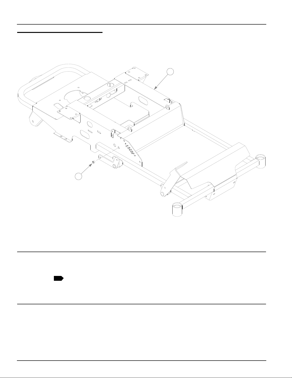
Rivet Nut Installation
2
1
ITEM
NO.
1
SERVICE
PART NO.
1 549873 110073 1 42" SPORT FRAME
549881 110099 1 48" SPORT FRAME
2 808485 808485 1 RIVET NUT, 5/16-18 THREAD
MFG. PART
NO.
QTY. DESCRIPTION
NOTES:
1. Service part includes Item 2 and decals (Page 8-2)
2-2 110907 01/09
Page 11

Chapter 3 Contents
Battery Installation. . . . . . . . . . . . . . . . . . . . . . . . . . . . . . . . . . . . . . . 3-2
Deck Lift Assembly . . . . . . . . . . . . . . . . . . . . . . . . . . . . . . . . . . . . . . 3-4
Hydraulic System Installation. . . . . . . . . . . . . . . . . . . . . . . . . . . . . . . 3-6
Steering Sub-Assembly. . . . . . . . . . . . . . . . . . . . . . . . . . . . . . . . . . . 3-8
Steering Assembly. . . . . . . . . . . . . . . . . . . . . . . . . . . . . . . . . . . . . . 3-10
Park Brake Assembly . . . . . . . . . . . . . . . . . . . . . . . . . . . . . . . . . . . 3-12
110907 01/09 3-1
Page 12
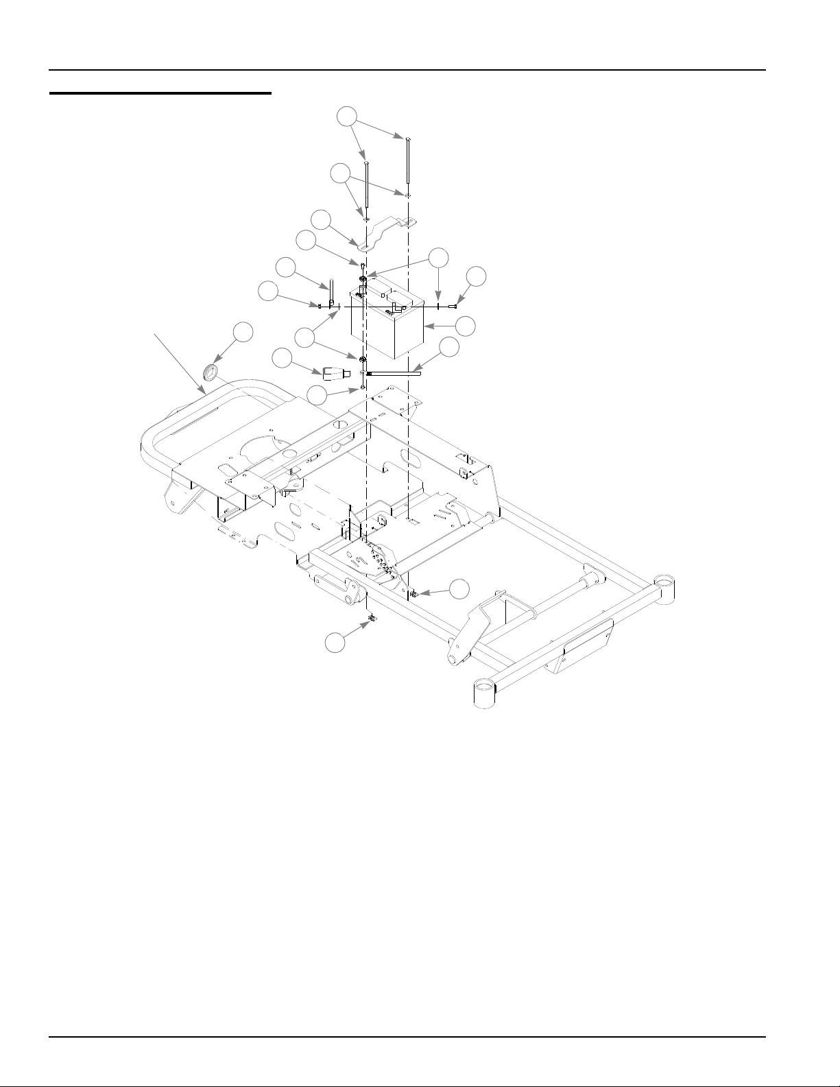
Battery Installation
TRACTOR
FRAME
3
4
5
1
8
11
2
11
12
9
6
8
7
10
7
6
3-2 110907 01/09
Page 13

Battery Installation
1
2
ITEM
NO.
10 740696 740696 1 BATTERY
11 601982 601982 2 CN .250-20X.150 MAX THK
12 794644 794644 1 GM 1.50 X 2.12 X 1.75
SERVICE
PART NO.
1 601930 601930 2 CS .250-20 X 6.50 HX G5
2 768515 768515 2 FW .281 X .625 X .051/.080H
3 348417 348417 1 BATTERY CLAMP STRAP
4 601062 601062 1 BATTERY CABLE, POS.
5 601841 601841 1 BATTERY CABLE, NEGATIVE
6 024927 024927 2 NT .250-20 HX GR.5 ZNYC
7 029868 029868 4 LW .250 INT-EXT TOOTH ZN
8 055939 055939 2 CS .250-20 X .750 HX G5 ZN
9 771428 771428 1 BATTERY CBL BOOT-RED
MFG.
PART NO.
QTY DESCRIPTION
NOTES:
1. When performing service on mower, disconnect battery ground cable
and black wire of harness and do not reconnect to battery until engine is
ready to be started. See Owners Manual.
2. Battery is not installed in export models. Hardware used for fastening
battery cables to battery to be installed and tightened to battery cables.
Battery clamp strap and associated hardware to be installed as shown
with capscrews (Items 1) bottomed out on threads of clip nuts (Items
11).
110907 01/09 3-3
Page 14
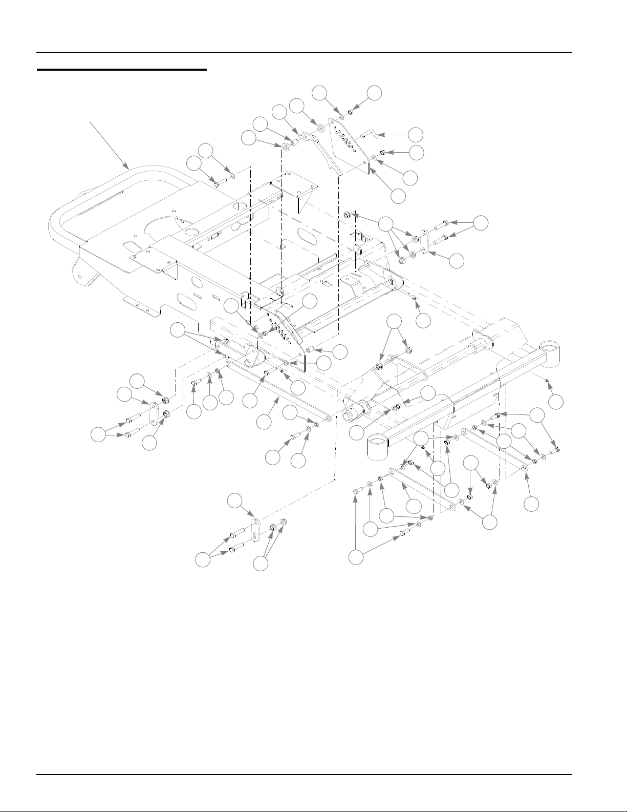
Deck Lift Assembly
TRACTOR
FRAME
6
1
7
6
2
6 7
3
4
5
3
8
5
7
9
9
16
10
9
11
6
12
13
8
6
11
6
12
9
6
7
10
14
9
11
6
12
15
6
7
6
12
6
11
7
10
16
9
15
6
17
17
17
17
3-4 110907 01/09
Page 15

Deck Lift Assembly
ITEM
NO.
1 110282 110282 1 DECK ADJUSTMENT PLATE LH
2 601963 601963 1 PIN, DECK HEIGHT STOP
3 769257 769257 2 FW, 656X1.250X.250 ZNY
4 110829 110829 1 HANDLE, DECK HT LOCK
5 348862 348862 2 STEERLEVER BUSHING
6 767954 767954 16 FW .406X.812X.060 SAE
7 054502 054502 8 NT .375-16 HX GRD 5 ZNY
8 080655 080655 2 CS .375-16X1.500 HX G5
9 704643 704643 12 NT .437-14 HX FLG ZN
10 055749 055749 6 CS .437-14X1.750 HX G5
11 036244 036244 6 CS .375-16X1.000 HX G5
12 601839 601839 6 PIVOT SPACER BUSHING
13 110884 110884 1 LIFT PEDAL LINK, SPORT
14 110880 110880 1 DECK LIFT LINK, SPORT
15 110879 110879 2 PULLER STRAP, SPORT
16 110929 110929 2 DECK LIFT LINK, NON-SLOT
17 015495 015495 4 GREASE FITTING STRAIGHT
SERVICE
PART NO.
MFG.
PART NO.
QTY DESCRIPTION
NOTES:
110907 01/09 3-5
Page 16
Hydraulic System Installation
2
20
19
1
13
14
14
15
1
2
11
1
2
3
3
3
10
4
7
22
6
25
9
10
8
12
5
23
24
3
17
17
3
3
18
18
17
15
3
16 17
3
3
1
21
19
20
2
15
16
5
21
15
10
3
3-6 110907 01/09
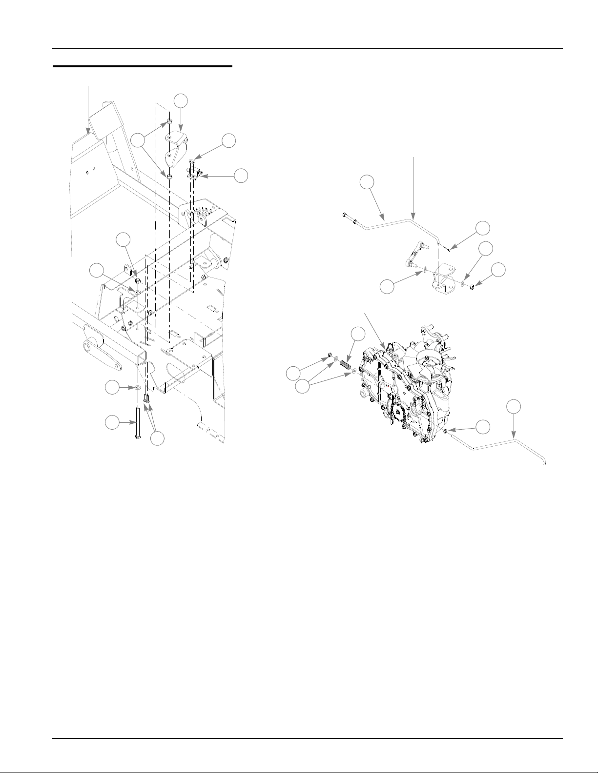
Page 17

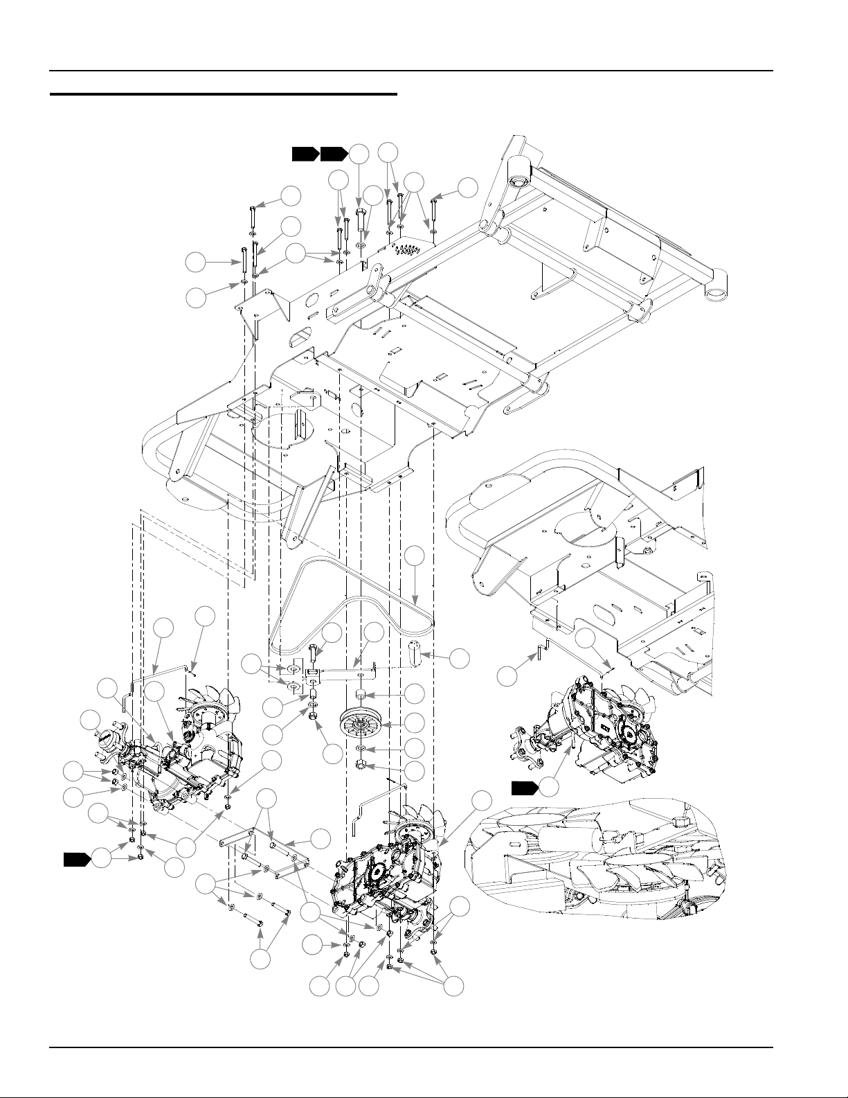
Hydro Transmission Installation
INDEX NO.
1 043067 043067 4 CS .312-18X3.00 HX G5 Z
2 710087 710087 4 CS .312-18X2.500 HX G5
3 768523 768523 16 FW .343X.687X.051/.080H
4 769133 769133 1 BELT, A 67.24" EL
5 602026 602026 2 BEARING DISC
6 111079 111079 1 PUMP IDLER, FORMED
7 036384 036384 1 SPRING 1/4 COIL PL 1.23
8 016972 016972 1 NT .625-11 HX G5 ZNYC
9 784827 784827 1 PULLEY, IDLER, 4.00"OD,
10 028118 028118 3 FW .625X1.00X.134 ZNYC
11 601983 601983 1 CS .625-11 X 2.25 HXG5ZY
12 601390 601390 1 EZT, 19.2 LEFT TRANS
13 110042 110042 1 HYDROSTAT CROSS BRACE
14 056036 056036 4 CS .375-16X2.250 HX G5
15 767954 767954 8 FW .406X .812 X.060 SAE
16 054502 054502 4 NT .375-16 HX GRD 5 ZNY
17 034272 034272 8 NT .312-18 HX G5 ZNYC
18 601391 601391 1 EZT, 19.2 RIGHT TRANS
19 793174 793174 2 TOWLINK ROD
20 048553 048553 2 CP .062DX1.000 LG HML Z
21 601018 N/A 2 OVERFLOW HOSE
22 017616 017616 1 CS .500-13X1.750 HX G5
23 602025 602025 1 BUSHING, IGUS .500 I.D.
24 781567 781567 1 NT .500-13 HX G8 ZY NL
25 601398 601398 1 SPACER, SPORT IDLER
SERVICE
PART NO.
MFG. PART
NO.
QTY. DESCRIPTION
NOTES:
1. Torque to 17 ft-lbs.
2. Torque to 100 ft-lbs.
3. Service parts available for the transaxles:
PART
NUMBER
788877 AXEL NUT 791723F FW .530 X 1.63 X .06 SLO
601206 EZT PULLEY KIT 788232 HUB ASSEMBLY
601207 PULLEY, 4.5", FST ZT2800 798363 PARKING BRAKE GEAR
795039 LEFT EZ VENT TUBE ASSY 795062 RIGHT EZT VENT HOSE
DESCRIPTION
4. Push all the slack in the transmission to rear and then tighten bolts.
110907 01/09 3-7
PART
NUMBER
DESCRIPTION
Page 18
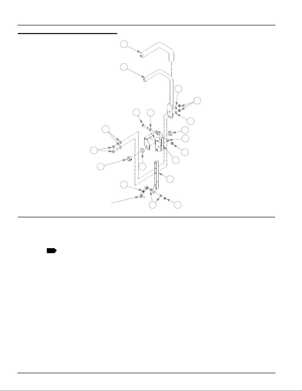
Steering Sub-Assembly
2
4
9
4
11
5
12
8
6
1
4
CONNECTS TO
PARK BRAKE
LINKAGE
10
3
6
7
4
14
13
4
1
ITEM NO.
1 781260 781260 2 GRIP, STEERING BAR
2 110370 110370 2 STEERING BAR W/A
3 705178 705178 2 CS .375-16X1.750 HX G5
4 767954 767954 2 FW .406X .812 X.060 SAE
5 054502 054502 4 NT .375-16 HX GRD 5 ZNY
6 770867 770867 4 BUSHING, PLAS .750X1(FS)
7 086660 086660 2 NT .375-16 HXZY NL
8 080655 080655 4 CS .375-16X1.500 HX G5
9 784439 784439 2 LOCK COLLAR,0.757 ID(FS)
10 110008 110008 1 STEERING BOX LH (PLATED)
11 796615 796615 2 BALL JOINT LINK MINI FS
12 023655 023655 2 NT .312-24 HXZY NL
13 110089 110089 2 CONTROL LEVER W/A
14 768523 768523 4 FW .343X.687X.051/.080H
SERVICE
PART NO.
110007 110007 1 STEERING BOX RH (PLATED)
MFG. PART
NO.
QTY. DESCRIPTION
NOTES:
1. Includes Item 1 (781260 Steering Bar Grip).
3-8 110907 01/09
Page 19

This page intentionally left blank.Steering Assembly
See “Steering Sub-Assembly” on
page 3-8.
1
2
5
3
2
3
4
3
6
3
7
4
10
9
8
11
11
12
3
3
3
110907 01/09 3-9
Page 20

Steering Assembly
ITEM
NO.
1 600221 600221 2 DAMPER, STEERING
2 023655 023655 4 NT .312-24 HXZY NL
3 768523 768523 12 FW .343X.687X.051/.080H
4 034272 034272 4 NT .312-18 HX G5 ZNYC
5 600981 600981 2 PUMP ROD ASSEMBLY
6 034280 034280 1 CS .312-18X .750 HX G5
7 110014 110014 1 PIVOT TUBE ASSEMBLY
8 705178 N/A 2 CS .375-16X1.750 HX G5
9 767954 767954 4 FW .406X .812 X.060 SAE
10 086660 N/A 2 NT .375-16 HXZY NL
11 781922 781922 4 BALL STUD, DAMPER (FS)
12 029876 029876 2 LW .312 INT-EXT TOOTH Z
SERVICE
PART NO.
PART NO.
1. Service parts for Damper:
MFG.
QTY DESCRIPTION
NOTES:
PART
NUMBER
601425 CONNECTOR BODY
601426 CAP LOCK
DESCRIPTION
3-10 110907 01/09
Page 21
Park Brake Assembly
12
8
8
BELL CRANK
DETAIL
CONNECTS TO
STEER PIVOT W/A
HYDRO-
TRACTOR FRAME
TRANSMISSION
12
6
7
1
2
3
5
10
9
7
13
14
15
9
4
11
110907 01/09 3-11
Page 22

Park Brake Assembly
ITEM
NO.
1 110001 110001 1 BRAKE ACTUATOR LH
2 765339 765339 4 BUSHING,IGUS#0608 (FS)
3 781211 781211 2 SWITCH, PUSH BUTTON(FS)
4 063198 063198 4 CS 10-24X .750 HXFLK ZN
5 601822 601822 2 NUT PLATE, .420 CENTERS
6 725796 725796 2 CS .375-16X4.00 HX G8 Z
7 767954 767954 4 FW .406X .812 X.060 SAE
8 110009 110009 2 BRAKE ACTUATOR ROD
9 768523 768523 8 FW .343X.687X.051/.080H
10 048553 048553 2 CP .062DX1.000 LG HML Z
11 023655 023655 4 NT .312-24 HXZY NL
12 068551 068551 4 NT .250-20 HXZY NL
13 086660 086660 2 NT .375-16 HXZY NL
14 768515 768515 4 FW .281X.625X.051/.080H
15 601131 601131 2 SPRING, BRAKE ARM RET.
SERVICE
PART NO.
110000 110000 1 BRAKE ACUTATOR RH
MFG.
PART NO.
QTY DESCRIPTION
NOTES:
3-12 110907 01/09
Page 23

Chapter 4 Contents
Briggs and Stratton 17.5 & 21 HP Engine Installation. . . . . . . . . . . . 4-2
Fuel System Installation. . . . . . . . . . . . . . . . . . . . . . . . . . . . . . . . . . . 4-4
Instrument Panel Installation . . . . . . . . . . . . . . . . . . . . . . . . . . . . . . . 4-6
Electrical Schematic - Briggs and Stratton (601676). . . . . . . . . . . . . 4-8
110907 01/09 4-1
Page 24
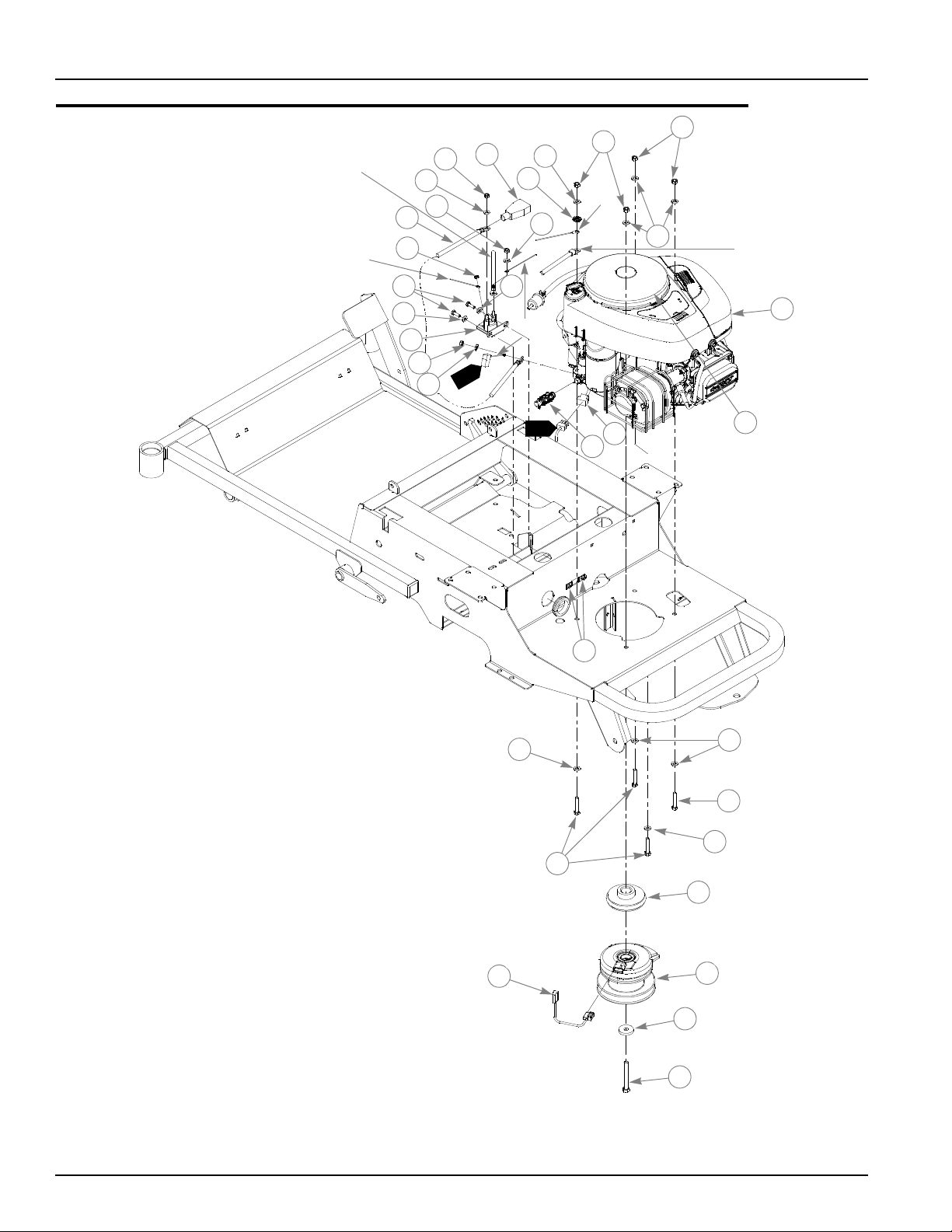
Briggs and Stratton 17.5 & 21 HP Engine Installation
14
1
12
4
3
16
6
7
10
9
8
5
5
3
3
3
2
2
3
13
11
11
13
11
13
13
POSITIVE
BATTERY
CABLE
ORANGE
BLK
RED
18
17
1
1
20
15 13
22
21
NEGATIVE
BATTERY
CABLE
4-2 110907 01/09
Page 25

Briggs and Stratton 17.5 & 21 HP Engine Installation
ITEM
NO.
1 601800 601800 1 ENGINE 17.5 HP BRIGGS
2 034272 034272 4 NT .312-18 HX G5 ZNYC
3 768523 768523 8 FW .343X.687X.051/.080H
4 029876 029876 1 LW .312 INT-EXT TOOTH Z
5 052837 052837 4 CS .312-18X1.750 HX G5
6 793760 793760 1 PULLEY,ENGINE-HYDRO DRI
7 601801 601801 1 CLUTCH WARNER I-5217-53
8 791251 791251 1 HARNESS, CLUTCH PIGTAIL
9 763417 763417 1 FW .454X1.50X.250
10 601834 601834 1 CS .437-20 X 3.50 HX G5
11 024927 024927 3 NT .250-20 HX GR.5 ZNYC
12 044255 044255 1 NT #10-32 HX ZN
13 768515 768515 4 FW .281X.625X.051/.080H
14 030817 030817 1 STARTER SOLENOID HW KIT
15 055939 055939 2 CS .250-20X .750 HX G5
16 601818 601818 1 OIL DRAIN - 3/8-18 NPTF
17 601676 601676 1 WIRE HARNESS, FST SPORT
18 601840 601840 1 BATTERY CABLE, POS.
19 104786 104786 1 OIL DRAIN HOSE (NOT SHOWN)
20 601844 601844 1 BRIGGS CONTACT COVER
21 601982 601982 2 CN .250-20X .150 MAX THK
22 771428 771428 1 BATTERY CBL BOOT-RED(FS)
SERVICE
PART NO.
601850 601850 1 ENGINE 21 HP BRIGGS
MFG.
PART NO.
QTY DESCRIPTION
NOTES:
1. Part of Item 17 (601676 Tractor Wire Harness).
2. Engine oil capacity: Refer to engine owner’s manual. Tighten dipstick
before checking.
3. Engine RPM to be set at 3450± 50.
4. Air filter service parts:
601846 FILTER, AIR PRECLEANER, BRIGGS 17.5
601847 FILTER, AIR FLAT PANEL, BRIGGS 17.5
601848 FILTER. AIR PRECLEANER, BRIGGS 21
601849 FILTER, AIR FLAT PANEL, BRIGGS 21
110907 01/09 4-3
Page 26
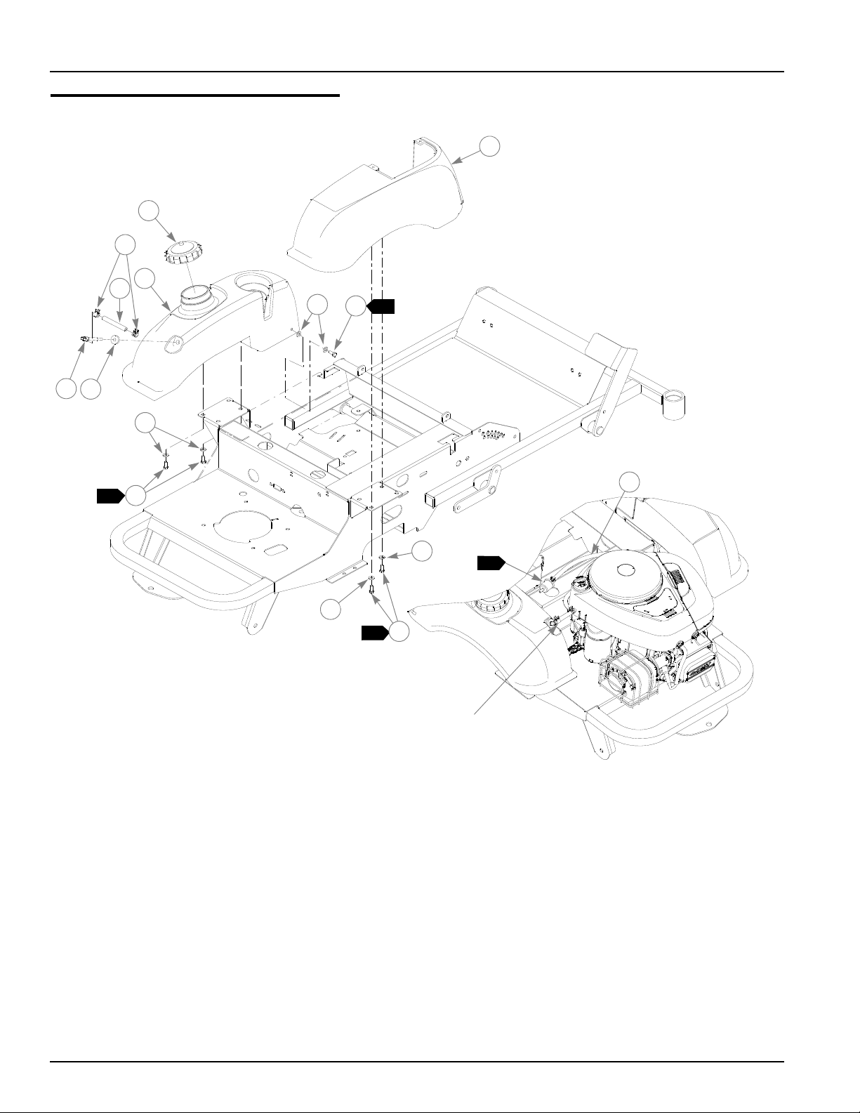
Fuel System Installation
FUEL LINE CONNECTS
TO FUEL FILTER
1
1
2
3
6
1
6
7
ENGINE NOT SHOWN
FOR CLARITY
5
4
6
7
9
8
7
3
6
10
1
4-4 110907 01/09
Page 27

Fuel System Installation
ITEM
NO.
1 779306 779306 1 3.5" FUEL CAP
2 110080 110080 1 FENDER RH
3 110081 110081 1 FENDER TANK LH
4 785295 N/A 1 GROMMET, FUEL SHUTOFF VALVE
5 601805 N/A 1 SUCTION HOSE ASSY 22.0
6 768523 768523 8 FW .343X.687X.051/.080H
7 034280 034280 6 CS .312-18X .750 HX G5
8 000323 000323 2 CLIP
9 015818 015818 1 FUEL LINE, 9"
10 015818 015818 1 FUEL LINE, 12"
SERVICE
PART NO.
MFG.
PART NO.
QTY DESCRIPTION
NOTES:
1. Torque to 7 ft-lbs.
2. Service parts for fuel tanks (not shown):
SERVICE PART NO. DESCRIPTION
785295 FLANGE GROMMET
601805 SUCTION HOSE ASSY 22.0
110907 01/09 4-5
Page 28

Instrument Panel Installation
RIGHT SIDE
FENDER
7
2
8
8
3
11
10
9
4
1
9
6
5
6
3
12
10
1
4-6 110907 01/09
Page 29

Instrument Panel Installation
ITEM
NO.
1 776476 776476 1 SWITCH, PTO 6201-321(FS)
2 785808 785808 1 KEY ASSEMBLY (FS)
3 045898 045898 1 IGN SWITCH INDAK 3H463
4 026237 N/A 2 RELAY
5 601803 601803 1 THROTTLE/CHOKE CABLE ASSY
6 601098 601098 2 CB 10-24 X .500 ZYNC
7 110085 110085 1 INSTRUMENT PANEL SPORT
8 704932 704932 2 FW .219X .500X.048 ZNYC
9 059832 059832 2 NT #10-24 HX NL ZN
10 768515 768515 3 FW .281X.625X.051/.080H
11 055947 055947 3 CS .250-20X .500 HX G5
12 601089 601089 2 RIVET .188 DIA BLK HD
SERVICE
PART NO.
MFG.
PART NO.
1. Part of 601676 (Wire Harness).
QTY DESCRIPTION
NOTES:
110907 01/09 4-7
Page 30

Electrical Schematic - Briggs and Stratton (601676)
4-8 110907 01/09
Page 31

Chapter 5 Contents
Front Wheel Assembly. . . . . . . . . . . . . . . . . . . . . . . . . . . . . . . . . . . . 5-2
Front Wheel Breakdown - 768044. . . . . . . . . . . . . . . . . . . . . . . . . . . 5-4
Drive Wheel Assembly Installation . . . . . . . . . . . . . . . . . . . . . . . . . . 5-5
Anti-Rollover Wheel Assembly . . . . . . . . . . . . . . . . . . . . . . . . . . . . . 5-6
110907 01/09 5-1
Page 32

Front Wheel Assembly
TRACTOR
FRAME
1
1
2
3
3
3
3
1
2
4
3
4
6
8
8
10
9
1
2
3
5
4
8
6
10
5
7
7
8
4
4
4
11
11
5
5-2 110907 01/09
Page 33

Front Wheel Assembly
ITEM NO.
1 705954 705954 2 CS .500-13 X 1.25 HX G5 ZN
2 344267 344267 2 FW .510 X 2.15 X .187 SPL ZN
3 712976 712976 2 FW .531X 1.375X.125 ZNY
4 784223 784223 4 BEARING W/O COLLAR
5 784603 784603 2 SPACER
6 339689 339689 2 CASTER FORK
7 042630 042630 2 CS .500-13X6.50 HX G5 Z
8 767962 767962 4 FW .531X 1.063X.090 SAE
9 781567 781567 2 NT .500-13 HX G8 ZY NL
10 768044 768044 2 TIRE/WHL 11X4-5 RIBBED
11 306969 306969 2 GAGE WHEEL SPACER
SERVICE
PART NO.
MFG. PART
NO.
QTY DESCRIPTION
NOTES:
1. Apply grease to zerks (see owners manual).
2. Tighten, then back off until wheel spins freely.
3. Assemble with extended inner race down. Apply a thin continuous bead
of Loctite® 609 to O.D. of outer races of bearings prior to assembling
bearing into frame.
4. Apply Loctite® 242 to threads.
5. Appy Anti-Sieze to caster pivot shaft.
110907 01/09 5-3
Page 34

Front Wheel Breakdown - 768044
1
2
2
768044
ITEM
NO.
1 772814 N/A 1 3/4” ROLLER BEARING
2 772806 N/A 2 BEARING CAP
SERVICE
PART NO.
1. Inflate tire to 8-12 psi.
MFG.
PART NO.
QTY DESCRIPTION
NOTES:
5-4 110907 01/09
Page 35

Drive Wheel Assembly Installation
2
1
5
2
4
3
1
ITEM
NO.
1 601810 601810 2 TIRE/WHEEL 18X8.5-8
2 601821 N/A TIRE 18 X 8.5 - SPORT
3 601820 N/A WHEEL 8 X 6.93 - SPORT
4 019521 N/A TIRE VALVE TR-412 GOODY
5 061077 061077 8 WHEEL NUT
SERVICE
PART NO.
MFG.
PART NO.
QTY DESCRIPTION
NOTES:
1. Torque to 65-75 ft. lbs.
2. Inflate tire to 8-12 psi.
110907 01/09 5-5
Page 36

Anti-Rollover Wheel Assembly
TRACTOR
FRAME
1
6
2
3
4
5
5
1
ITEM
NO.
1 781708 N/A 2 CS .500-13X4.250 HX G5
2 767962 N/A 4 FW .531 X 1.063 X .090 SAE HD ZN
3 031997 N/A 2 ANTI-SCALP WHEEL
4 053199 N/A 2 NT .500-13 HX JAM ZNYC
5 344267 344267 4 FW .510X 2.15X.187 SPL
6 781567 781567 2 NT .500-13 H8ZY NL
1. Includes items 1 through 4.
SERVICE
PART NO.
MFG.
PART NO.
788166 788166 2 ANTI-SCALP WHEEL ASSEMBLY
QTY DESCRIPTION
NOTES:
5-6 110907 01/09
Page 37

Chapter 6 Contents
48" Side Discharge Deck Assembly . . . . . . . . . . . . . . . . . . . . . . . . . 6-2
48" Side Discharge Deck Pulley Assembly . . . . . . . . . . . . . . . . . . . . 6-4
42" Side Discharge Deck Assembly . . . . . . . . . . . . . . . . . . . . . . . . . 6-6
42" Side Discharge Deck Pulley Assembly . . . . . . . . . . . . . . . . . . . . 6-8
110907 01/09 6-1
Page 38

48" Side Discharge Deck Assembly
4
2
3
4
10
3
1
17
7
11
8
6
9
5
6
12
13
13
15
16
11
16
15
12
14
14
6-2 110907 01/09
Page 39

48" Side Discharge Deck Assembly
1
ITEM
NO.
1 550017 109754 1 48" DECK WA
2 601117 601117 1 RUBBER CHUTE ASSEMBLY
3 086660 086660 4 NT .375-16 HXZY NL
4 767954 767954 4 FW .406 X .812 .060 SAE HD ZN
5 034272 034272 1 NT .312-18 HX G5 ZNYC
6 768523 768523 2 FW .343X.687X.051/.080H
7 108049 108049 1 BRACKET CHUTE W/A
8 108537 108537 1 PIN CHUTE MTG W/A
9 034280 034280 1 CS .312-18X .750 HX G5
10 110913 110913 1 CHUTE ADAPTER 48 SPORT
11 025395 025395 4 CB .375-16 X 1.00 STD CD
12 781708 N/A 4 CS .500-13 X 4.25 HX G5 ZN
13 767962 N/A 8 FW .531 X 1.063 X .090 SAE HD ZN
14 031997 N/A 4 ANTI-SCALP WHEEL
15 053199 N/A 4 NT .500-13 HX JAM ZN
16 781567 781567 2 NT .50-13 HX LK NY
17 601069 601069 2 CN .312-18X.200 MAX THK
SERVICE
PART NO.
788166 788166 2 ANTI SCALP WHEEL ASSY
MFG.
PART NO.
QTY DESCRIPTION
NOTES:
1. Includes items 12, 13, 14, and 15.
2. Service part deck includes decals (see “48" Side Discharge Deck
Decals” on page 8-4).
110907 01/09 6-3
Page 40

48" Side Discharge Deck Pulley Assembly
2
3
1
9
4
5
8
7
2
3
DECK ASSY
6
1
10
2
3
5
5
4
15
16
17
11
12
14
19
18
11
12
13
12
20
19
22
23
24
25
21
6-4 110907 01/09
Page 41

48" Side Discharge Deck Pulley Assembly
4
ITEM
NO.
1 771634 771634 1 B-SECTION BELT
2 794446 794446 3 CS .625-11X1.500 HX G5
3 046821 046821 3 FW .656X 2.00X.078 ZNYC
4 797449 797449 4 FW .650X1.125X.18 ZNYCG5
5 784504 784504 3 PULLEY, IDLER, 5.00"OD
6 109770 109770 1 IDLER SLIDE W/A
7 781302 781302 1 IDLER SPRING
8 259812 059931 1 CHAIN DECK LIFT SPRING (13 LINKS)
9 784199 784199 4 CS .312-18X1.250 FLT SH
10 601619 601619 2 IDLER SLIDE UHMW RT & LT
11 034280 034280 2 CS .312-18X .750 HX G5
12 768523 768523 6 FW .343X.687X.051/.080H
13 110840 110840 1 PULLEY COVER, LH
14 110841 110841 1 PULLEY COVER, RH
15 705954 705954 3 CS .500-13X1.25 HX G5 Z
16 798603 798603 3 FW .515X1.65X.125 HD ZY
17 792689 792689 3 PULLEY 5.00"OD
18 054502 054502 12 NT .375-16 HX GRD 5 ZNY
19 767954 767954 24 FW .406X .812 X.060 SAE
20 058776 058776 4 NT .312-18 HXZY NL
21 601804 601804 3 SPINDLE ASSEMBLY
22 005116 005116 12 CS .375-16X1.375 HX G5
23 601123 601123 3 BLADE, 16.50"-L-F-CW
24 782474 782474 3 CW .631 2.250X .187 PNT
25 781872 781872 3 CS .625-11X1.25 HX G5 Z
SERVICE
PART NO.
MFG.
PART NO.
QTY DESCRIPTION
NOTES:
1. Torque to 73 ft. lbs.
2. Torque to 145 ft-lbs.
3. See “48" Deck Belt Routing and Tensioning” on page 7-6 for belt
tensioning.
4. See “Spindle Assembly–601804” on page 6-10 for breakdown.
110907 01/09 6-5
Page 42

42" Side Discharge Deck Assembly
1
2
6
7
3
4
4
5
3
4
8
8
9
14
13
10
12
11
1
6-6 110907 01/09
Page 43

42" Side Discharge Deck Assembly
3
2
ITEM
NO.
1 550011 110150 1 42" DECK WA
2 601117 601117 1 RUBBER CHUTE ASSEMBLY
3 086660 086660 6 NT .375-16 HXZY NL
4 767954 767954 8 FW .406 X .812 .060 SAE HD ZN
5 036244 036244 2 CS .375-16X1.000 HX G5
6 357103 357103 1 DISCHARGE CHUTE BRACKET W/A
7 110912 110912 1 DISCHARGE SPORT ADAPTER
8 025395 025395 4 CB .375-16 X 1.00 STD CD
9 601069 601069 4 CN .312-18X.200 MAX THK
10 781708 N/A 1 CS .500-13 X 4.25 HX G5 ZN
11 767962 N/A 2 FW .531 X 1.063 X .090 SAE HD ZN
12 031997 N/A 1 ANTI-SCALP WHEEL
13 053199 N/A 1 NT .500-13 HX JAM ZN
14 781567 781567 1 NT .50-13 HX LK NY
SERVICE
PART NO.
788166 788166 1 ANTI SCALP WHEEL ASSY
MFG.
PART NO.
QTY DESCRIPTION
NOTES:
1. Do not torque, Item 2 (601117 Discharge Chute) must pivot freely.
2. Includes items 10, 11, 12, and 13.
3. Service part deck includes decals (see “42" Side Discharge Deck
Decals” on page 8-5 for listing of decals).
110907 01/09 6-7
Page 44

42" Side Discharge Deck Pulley Assembly
2
3
1
2
5
6
3
4
DECK ASSY
1
78
9
10
2
3
4
4
5
11
12
13
14
15
16
17
18
16
20
19
21
22
23
24
25
24
25
24
25
26
24
6-8 110907 01/09
Page 45

42" Side Discharge Deck Pulley Assembly
4
ITEM
NO.
1 600726 600726 1 BELT, A 114.3" EL (42" DECK)
2 794446 794446 2 CS .625-11X1.500 HX G5
3 046821 046821 2 FW .656X 2.00X.078 ZNYC
4 797449 797449 4 FW .650X1.125X.18 ZNYCG5
5 784504 784504 2 PULLEY, IDLER, 5.00"OD
6 109770 109770 1 IDLER SLIDE W/A
7 781302 781302 1 IDLER SPRING
8 259812 059931 1 CHAIN DECK LIFT SPRING (13 LINKS)
9 784199 784199 4 CS .312-18X1.250 FLT SH
10 601619 601619 2 IDLER SLIDE UHMW RT & LT
11 705954 705954 2 CS .500-13X1.25 HX G5 Z
12 798603 798603 2 FW .515X1.65X.125 HD ZY
13 793778 793778 2 DECK SPINDLE PULLEY
14 045765 045765 2 FW 1.030X 1.500X.134 ZN
15 054502 054502 8 NT .375-16 HX GRD 5 ZNY
16 767954 767954 16 FW .406X .812 X.060 SAE
17 110892 110892 1 PULLEY COVER, LH
18 110891 110891 1 PULLEY COVER, RH
19 601804 601804 2 SPINDLE ASSEMBLY
20 005116 005116 8 CS .375-16X1.375 HX G5
21 793794 793794 2 BLADE,20.50"-L-F-CW
22 782474 782474 2 CW .631 2.250X .187 PNT
23 781872 781872 2 CS .625-11X1.25 HX G5 Z
24 768523 768523 8 FW .343X.687X.051/.080H
25 034280 034280 4 CS .312-18X .750 HX G5
26 058776 058776 4 NT .312-18 HXZY NL
SERVICE
PART NO.
MFG.
PART NO.
QTY DESCRIPTION
NOTES:
1. Torque to 73 ft. lbs.
2. Torque to 145 ft-lbs.
3. See “42" Deck Belt Routing and Tensioning” on page 7-7 for belt
tensioning.
4. See “Spindle Assembly–601804” on page 6-10 for breakdown.
110907 01/09 6-9
Page 46

Spindle Assembly–601804
1
2
2
3
4
5
ITEM
NO.
1 783548 N/A 1 BLADE SPINDLE RETAINING RING
2 601827 N/A 2 BLADE SPINDLE BEARING
3 601830 N/A 1 BLADE SPINDLE SPACER
4 601828 N/A 1 BLADE SPINDLE HOUSING
5 601829 N/A 1 BLADE SPINDLE SHAFT
SERVICE
PART NO.
MFG.
PART NO.
QTY. DESCRIPTION
NOTES:
6-10 110907 01/09
Page 47

Chapter 7 Contents
Seat Installation . . . . . . . . . . . . . . . . . . . . . . . . . . . . . . . . . . . . . . . . 7-2
Deck Installation . . . . . . . . . . . . . . . . . . . . . . . . . . . . . . . . . . . . . . . . 7-4
48" Deck Belt Routing and Tensioning . . . . . . . . . . . . . . . . . . . . . . . 7-6
42" Deck Belt Routing and Tensioning . . . . . . . . . . . . . . . . . . . . . . . 7-7
110907 01/09 7-1
Page 48

Seat Installation
3
1
8
6
1
3
4
3
2
14
10
7
3
5
3
1
9
10
11
12
13
7-2 110907 01/09
Page 49

Seat Installation
ITEM
NO.
1 601807 601807 1 SEAT-SPORT
2 052860 052860 2 CS .375-16X1.250 HX G5
3 767954 767954 12 FW .406X .812 X.060 SAE
4 793851 793851 2 SPRING,COMP 1.25X4.00X.
5 054502 054502 2 NT .375-16 HX GRD 5 ZNY
6 036244 036244 2 CS .375-16X1.000 HX G5
7 086660 086660 2 NT .375-16 HXZY NL
8 110835 110835 1 SEATPAN, SPORT
9 756270 756270 2 CS .312-18X1.50 FLTHR G
10 768523 768523 6 FW .343X.687X.051/.080H
11 110876 110876 1 CATCH, SPORT SEAT PAN
12 070557 070557 2 NT .312-18 HX UNT ZN
13 601069 601069 2 CN .312-18X.200 MAX THK
14 034280 034280 4 CS .312-18X .750 HX G5
SERVICES
PART NO.
MFG.
PART NO.
QTY DESCRIPTION
NOTES:
1. Do not torque, Item 8 (Seat Pan) must pivot freely.
110907 01/09 7-3
Page 50

Deck Installation
TRACTOR
ASSEMBLY
DECK
ASSEMBLY
1
3
1
4
5
4
6
2
2
7-4 110907 01/09
Page 51

Deck Installation
ITEM
NO.
1 055749 N/A 6 CS .437-14X1.750 HX G5
2 704643 N/A 6 NT .437-14 HX FLG ZN
3 036244 036244 2 CS .375-16X1.000 HX G5
4 767954 767954 4 FW .406X .812 X.060 SAE
5 601839 N/A 2 PIVOT SPACER BUSHING
6 054502 054502 2 NT .375-16 HX GRD 5 ZNY
SERVICE
PART NO.
MFG.
PART NO.
QTY DESCRIPTION
NOTES:
1. 42" deck installation is shown, 48" deck is similar.
110907 01/09 7-5
Page 52

48" Deck Belt Routing and Tensioning
DECK
ASSEMBLY
1
NOTES:
1. Spring length after tensioning new belt. Measured from outside of hook
to outside of hook.
2. Route belt as shown.
7-6 110907 01/09
Page 53

42" Deck Belt Routing and Tensioning
DECK
ASSEMBLY
1
NOTES:
1. Spring length after tensioning new belt. Measured from outside of hook
to outside of hook.
2. Route belt as shown.
110907 01/09 7-7
Page 54

7-8 110907 01/09
Page 55

Chapter 8 Contents
Tractor Decals . . . . . . . . . . . . . . . . . . . . . . . . . . . . . . . . . . . . . . . . . . 8-2
48" Side Discharge Deck Decals. . . . . . . . . . . . . . . . . . . . . . . . . . . . 8-4
42" Side Discharge Deck Decals. . . . . . . . . . . . . . . . . . . . . . . . . . . . 8-5
110907 01/09 8-1
Page 56

Tractor Decals
6
12
11
9
7
8
4
3
10
13
14
15
17
16
18
8-2 110907 01/09
Page 57

Tractor Decals
1
2
5
ITEM
NO.
1 601812 601812 1 SPORT ID DECAL
2 727172 727172 1 DECAL 'MADE IN U.S.A.'
3 601814 601814 1 SPORT DECK HEIGHT DECAL
4 601813 601813 1 HUSTLER FRONT DECAL
5 782573 782573 1 DECAL, FIRST ZERO TURN
6 N/A 083279 1 SERIAL NO PLATE TURF PR
7 785139CE 785139CE 1 DECAL, STEERING L.S.
8 601981 601981 1 HUSTLER DECAL FRONT
9 785220CE 785220CE 1 DECAL, STEERING R.S.
10 601967 601967 1 DECAL, ENGINE DEPARTMENT
11 600941 600941 1 DECAL, PATENTS
12 600899 600899 1 DECAL, PUMP BELT WARNING
13 601815 601815 1 DECAL, BATTERY
14 601867 601867 1 DECAL, HUSTLER "H"
15 601811 601811 1 DASH DECAL INSTRUMENT
16 601986 601986 2 STEP TREAD, LOWER SPORT
17 110063 110063 2 GRIP TAPE
18 601987 601987 1 STEP TREAD, FOOT LIFT
SERVICE
PART NO.
MFG.
PART NO.
QTY. DESCRIPTION
NOTES:
110907 01/09 8-3
Page 58

48" Side Discharge Deck Decals
1
2
3
4
5
6
7
ITEM
NO.
1 793976 793976 1 48 DECK ID DECAL
2 794503 794503 1 STEP TREAD DECAL
3 601837 601837 1 DECK DANGERS DECAL
4 601817 601817 1 DISCHARGE DECAL
5 601892 601892 1 DECAL, THROWN OBJECTS, LARGE
6 601816 601816 1 DECAL, DECK DANGERS, SMALL
7 781419CE 781419CE 1 DECAL,Z DECK BELT RTG C
SERVICE
PART NO.
MFG.
PART NO.
QTY. DESCRIPTION
NOTES:
8-4 110907 01/09
Page 59

42" Side Discharge Deck Decals
1
5
6
2
3
4
7
ITEM
NO.
1 793521 793521 1 42 DECK ID DECAL
2 794503 794503 1 STEP TREAD DECAL
3 601837 601837 1 DECK DANGERS DECAL
4 793687 793687 1 BELT ROUTING DECAL
5 601816 601816 1 DECK DANGERS DECAL
6 601817 601817 1 DISCHARGE DECAL
7 601892 601892 1 DECAL, THROWN OBJECTS, LARGE
SERVICE
PART NO.
MFG.
PART NO.
QTY. DESCRIPTION
NOTES:
110907 01/09 8-5
Page 60

8-6 110907 01/09
Page 61

Chapter 9 Contents
Assembly Pictures and Aids . . . . . . . . . . . . . . . . . . . . . . . . . . . . . . . 9-3
General Information for all models . . . . . . . . . . . . . . . . . . . . . 9-3
Wire harness and cable routings . . . . . . . . . . . . . . . . . . . . . . 9-3
Fuel Lines . . . . . . . . . . . . . . . . . . . . . . . . . . . . . . . . . . . . . . . . 9-5
Maintenance & Adjustment Safety. . . . . . . . . . . . . . . . . . . . . . . . . . . 9-6
Safe Maintenance & Adjustment Practices. . . . . . . . . . . . . . . 9-6
Using a ramp. . . . . . . . . . . . . . . . . . . . . . . . . . . . . . . . . . . . . . 9-7
Safety and Instruction Decals. . . . . . . . . . . . . . . . . . . . . . . . . 9-7
Maintenance . . . . . . . . . . . . . . . . . . . . . . . . . . . . . . . . . . . . . . . . . . 9-10
Introduction. . . . . . . . . . . . . . . . . . . . . . . . . . . . . . . . . . . . . . 9-11
Torque values. . . . . . . . . . . . . . . . . . . . . . . . . . . . . . . . . . . . 9-12
Tires . . . . . . . . . . . . . . . . . . . . . . . . . . . . . . . . . . . . . . . . . . . 9-12
Lubrication . . . . . . . . . . . . . . . . . . . . . . . . . . . . . . . . . . . . . . 9-12
Electrical system. . . . . . . . . . . . . . . . . . . . . . . . . . . . . . . . . . 9-12
Access to Hydro-Gear EZT transmissions. . . . . . . . . . . . . . 9-14
Hydraulic system. . . . . . . . . . . . . . . . . . . . . . . . . . . . . . . . . . 9-14
Fuel system. . . . . . . . . . . . . . . . . . . . . . . . . . . . . . . . . . . . . . 9-15
Engine oil and filter . . . . . . . . . . . . . . . . . . . . . . . . . . . . . . . . 9-16
Belt replacement. . . . . . . . . . . . . . . . . . . . . . . . . . . . . . . . . . 9-17
Deck belt replacement . . . . . . . . . . . . . . . . . . . . . . . . . . . . . 9-18
Transaxle drive belt replacement . . . . . . . . . . . . . . . . . . . . . 9-18
Mower blade maintenance . . . . . . . . . . . . . . . . . . . . . . . . . . 9-19
Mower blade removal . . . . . . . . . . . . . . . . . . . . . . . . . . . . . . 9-21
Adjustment. . . . . . . . . . . . . . . . . . . . . . . . . . . . . . . . . . . . . . . . . . . . 9-22
Introduction. . . . . . . . . . . . . . . . . . . . . . . . . . . . . . . . . . . . . . 9-22
Control lever adjustment. . . . . . . . . . . . . . . . . . . . . . . . . . . . 9-22
Steering linkage . . . . . . . . . . . . . . . . . . . . . . . . . . . . . . . . . . 9-22
Control Lever Neutral Adjustment. . . . . . . . . . . . . . . . . . . . . 9-23
Steering dampener . . . . . . . . . . . . . . . . . . . . . . . . . . . . . . . . 9-25
Park brake spring adjustment. . . . . . . . . . . . . . . . . . . . . . . . 9-25
Hydraulic pump belt adjustment . . . . . . . . . . . . . . . . . . . . . . 9-26
110907 01/09 9-1
Page 62

Deck drive belt adjustment. . . . . . . . . . . . . . . . . . . . . . . . . . 9-26
Engine RPM setting . . . . . . . . . . . . . . . . . . . . . . . . . . . . . . . 9-27
Deck leveling and height adjustment . . . . . . . . . . . . . . . . . . 9-27
9-2 110907 01/09
Page 63

Assembly Pictures and Aids
PTO CLUTCH
SWITCH
TIE STRAPS
NEG. BATTERY CABLE
POS. BATTERY
CABLE
POS. BATTERY CABLE
FROM BATTERY
POS. BATTERY CABLE
TO STARTER
STARTER
SOLENOID
General Information for all models
Instrument panel (FIG. 1 & FIG. 2).
FIG. 1 FIG. 2
Wire harness and cable routings
Front of wire harness (FIG. 3). Route the 12" positive battery cable and the red wire through the cable boot prior to
fastening hardware to solenoid (FIG. 4).
FIG. 3 FIG. 4
110907 01/09 9-3
Page 64

Route battery cables and wireharness (from seat and safety switches) through hole in the left side of frame (FIG. 5).
WIREHARNESS
TIE STRAP
NEG. BATTERY CABLE
POS. BATTERY
CABLE
POSITIVE
BATTERY
TIE STRAP
NEGATIVE
BATTERY
CABLE
CABLE
WIRE
HARNESS
THROTTLE/
CHOKE
FUEL LINE
CABLE
CLUTCH
PIGTAIL
TIE STRAP
SAFETY SWITCH
FIG. 5 FIG. 6
Wire harness, battery cable, and throttle/choke cable, routing and tie straps (FIG. 7 & FIG. 8) .
Clutch pigtail to clutch anchor tie strap (FIG. 9).
Safety switches and tie straps (FIG. 10)
FIG. 7 FIG. 8
FIG. 9 FIG. 10
9-4 110907 01/09
Page 65

Engine connections (FIG. 11 & FIG. 12).
TIE STRAPS
OIL FILL
TUBE
THROTTLE/
CHOKE
CABLE
FUEL LINE
FUEL
LINE
TIESTRAP
FUEL FILTER
FIG. 11 FIG. 12
Fuel Lines
Fuel line routing (FIG. 13, & FIG. 14). Be sure fuel filter does not come in contact with engine.
FIG. 13 FIG. 14
1.
110907 01/09 9-5
Page 66

Maintenance & Adjustment Safety
This safety alert symbol is used to call attention to a message intended to provide a reasonable degree of
PERSONAL SAFETY for operators and other persons during the normal operation and servicing of this equipment.
DANGER
WARNING
This manual uses two other words to highlight information. IMPORTANT calls attention to special mechanical
information and NOTE: emphasizes general information worthy of special attention.
All operators should read this manual, or be instructed about safe operating and maintenance procedure s. Th is is
the owner’s responsibility.
Improper use or maintenance by the operator, mechanic, or owner can result in injury. To reduce the
potential for injury, comply with these safety instructions and always pay at tention to the saf ety alert
which means DANGER or WARNING—“personal safety instructions.” Failure to comply with the instructions
may result in personal injury or death.
Incorrect usage of this machine may result in severe injury. Personnel operating and maintaining it should
be trained in the proper use and should read the manuals completely and thor oughly befo re att empt ing to se tup, operate, adjust, or service this machine.
The Quick Reference Decals, located in front of and to the right of the seat, are designed to give the operator/
mechanic brief information needed in the daily operation and service of the machine. These decals are no t inte nded to
be used in place of this manual but instead is to be used as an extension of this manual. These decals should not be
removed or obliterated. Replace these decals if they become unreadable.
It is the owner’s responsibility to make certain th at the operator/mech anic reads and un derstands this man ual and
all decals before operating this machine. It is also the owner’s responsibility to make certain that the operator/
mechanic is a qualified and physically able individual, properly trained in the operation of this equipment. Local
regulations may restrict the age of the operator/mechanic.
The owner should also ensure that the operator/mechanic knows that they are responsible for their own safety as
well as the safety of other persons within the vicinity. Remember, the operator/mechanic is responsible for accident s or
hazards occurring to other people or their property.
—denotes immediate hazards which WILL result in severe personal injury or death.
—denotes a hazard or unsafe practice which COULD result in severe personal injury or death.
symbol,
?
Safe Maintenance & Adjustment Practices
This product is capable of amputating hands and feet and throwing objects. Always follow all safety instructions to
avoid serious injury or death.
?
Unless specifically required, DO NOT have engine running when servicing or making ad justments to tra ctor . Place
control levers in the park brake position, disengage deck clutch, remove ignition switch key and disconnect the
negative battery cable. Repairs or maintenance requ iring engine power sh ould be performed b y trained perso nnel
only. To prevent carbon monoxide poisoning, be sure proper ventilation is available when engine must be operated in an enclosed area.
?
Follow daily and weekly checklists, making sure hoses are tightly secured and bolts are tightened.
?
Keep your machine clean and remove any deposits of trash and clippings, which can cause engine fires and
hydraulic overheating as well as excessive belt wear. Clean up oil or fuel spillage. Allow machine to cool before
storing.
?
Clean flammable material from machine. Prevent fires by keeping engine compartment, batt ery, hydraulic
lines, fuel line, fuel tank and operator’s station clean of accumulated trash, grass clippings, and other
debris. Always clean up spilled fuel and oil.
?
Always wear adequate ear protection, such as earplugs, when operating this e quipment as prolonged exposu re to
uncomfortable or loud noises can cause impairment or loss of hearing. Do not wear radios or music headphones
while operating the machinery. Safe operation requires your full attention.
?
Never put hands or feet under any part of the machine while it is running.
9-6 110907 01/09
Page 67

?
Except when changing or checking belt, always keep belt covers on mower for safety as well as cleanliness.
?
Stop the engine before removing the grass catcher or unclogging the discharge chu te . Never clear the discharge
chute with the engine running. Turn off the engine and be sure the blades have stopped before cleaning. Use a
stick to clear a plugged discharge area. Never use your hand!
?
Exercise caution when loading or unloading the machine onto a trailer or truck.
?
Always wear safety goggles or safety glasses with side shields when operating the mower.
?
Never leave machine unattended with ignition key in switch, especially with children present.
?
Be alert and turn the machine off if children enter the area.
?
Always wear adequate eye protection when servicing the battery, hydraulic system, cooling system or when grinding mower blades and removing accumulated debris.
?
Use extra caution when handling gasoline and other fuels. They are flammable and vapors are explosive.
?
Never refuel tractor while engine is running; never refu el near an open flame or near devices which can create a
spark. Refuel outdoors preferably, or in well ventilated areas.
?
Never attempt to start engine when there is a strong odor of gasoline fumes present. Locate and correct cause.
?
Never run the engine in an enclosed area unless exhaust is vented to the outside. Exhaust gases contain carbon
monoxide which is odorless and deadly poison.
?
Never attempt to make any adjustments or repairs to the tractor drive system, mower deck or any attachment
while the tractor engine is running or deck clutch is engaged. Repairs or maintenance requiring engine power
should be performed by trained personnel only.
?
Never work under the machine or att achment unless it is safely supported with jack st ands. Make cert ain machine
is secure when it is raised and placed on the jack stands. The jack stands should not allow the machine to move
when the engine is running and the drive wheels are rotatin g. Use only certified jack stands. Use only appropri-
ate jack stands, with a minimum weight rating of 2000 pounds to block the unit up. Use in pairs only. Follow the
instructions supplied with the vehicle stands.
?
Before working on or under the deck, ma ke ce rtain eng ine cannot be accidentally started. Shut engine off and
remove ignition switch key for maximum safety. Repairs or maintenance requiring engine power should be performed by trained personnel only.
?
Use a stick or similar instrument to clean under the mower making sure that no part of the body, especially arms
and hands are under mower.
?
Exercise caution when working under the deck as the mower blades are extremely sharp. Wearing gloves or
wrapping the blade(s) is advisable when working around or with the blades.
?
Do not touch hot parts of machine.
?
Keep nuts and bolts tight, especially the blade attachment bolts. Keep equipment in good condition.
?
Never tamper with safety devices. Check their proper operation regularly.
?
Grass collection system components are subject to wear, damage and deterioration, which could expose moving
parts or allow objects to be thrown. Frequently chec k components an d replace with manufacturer’s recommended
parts, when necessary.
?
Use only genuine Hustler replacement parts to ensure that original standards are maintained
Using a ramp
?
Use extreme caution when loading and unloading a unit with a ramp.
?
Use only a single, full width ramp; do not use individual ramps for each side of the unit. Having a full width ramp
provides a surface for the tractor frame to contact if the unit starts to tip backwards. It also reduces the risk of a
wheel going off and the machine tipping over.
?
Do not exceed a 15 degree angle between the ramp and the ground or between the ramp and the trailer or truck.
?
When on a ramp avoid sudden acceleration
Safety and Instruction Decals
?
Specific safety warning decals are located on the equipment near the immediate areas of potential hazards.
These decals should not be removed or obliterated. Replace them if they become non-readable.
110907 01/09 9-7
Page 68

The following illustrations show the various decals that are located on the machine. A brief explanation, for those
Part Number
727016
Part Number
771436
Part Number
788968
Part Number
727420
Part Number
727438
Part Number
727453
requiring one, is shown to help the operator understand the meanings of these decals.
Read Owner’s Manual and Quick Reference Decal before attempting to operate this machine.
Avoid skin contact with battery acid.
Always wear eye protection when checking the battery, acid can cause serious injury to skin and
eyes. If contact occurs, flush area with clean water and call physician immediately. Acid will also
damage clothing.
Do not allow open flame near the battery when charging.
Hydrogen gas forms inside the battery. This gas is both toxic and flammable and may cause an
explosion if exposed to flame. Always remove the negative ground first and replace it last.
Do not overfill battery.
Electrolyte may overflow and damage paint, wiring or structure. When cleaning the battery, use
soap and water. Be careful no t to get soap and wa ter into the battery. Use soda mixed in water to
clean corrosion off the terminals.
Do not remove or modify stabilizer wheels or rear engine guard or injury can result.
Keep engine and pump compartment(s) clean (especially in exhaust area) to prevent fire
and provide maximum engine and hydraulic cooling.
Do not smoke while refueling.
Do not fill tank with engine running, or while the engine is hot.
Allow engine to cool before storing machine inside a building.
Store away from open flame or spark if there is fuel in tank.
Clean up any gasoline spills.
Do not refuel while in enclosed trailer or other enclosed areas.
Never operate the mower deck with side deflector remove d or in raised positio n, except when the
grass catcher attachment is being used.
Whirling blades! Keep hands and feet away.
Beware of thrown objects.
Keep shields or covers in place while machine is in operation.
Keep hands away from rotating pulleys and belts.
9-8 110907 01/09
Page 69

If you lose steering control while operating the machine, place the steering control levers in the
Part Number
600899
park brake position immediately. Inspect the machine and involve your Hustler dealer to resolve
the problem before continuing to operate.
If pump belt fails, steering control will be lost. Refer to owner’s manual for inspection and
replacement intervals and refer to above paragraph for emergency procedures.
110907 01/09 9-9
Page 70

8
1
11
11
10
10
6
7
7
16
2
9
4
9
5
12
14
14
13
Viewed from top of unit
1 Engine Oil Fill & Dipstick
2. Fuel Filter
3. Engine Air Cleaner
4. Engine Oil Drain Plug
5. Battery
6. Fuel Tanks
7. Gauge Wheel Bearing Zerks (2)
8. Engine Oil Filter
9. Deck Lift Pivot Zerks (4)
10. Park Brake Switch (2)
11. Drive Tire
12. Deck Belt
13. Pump Belt
14. Blades
15. Engine Air Intake Screen
16. Front Gauge Wheel Tires
Maintenance Locator Chart
Viewed from bottom of unit
Viewed from top of unit
Maintenance
FIG. 15
9-10 110907 01/09
Page 71

WEEKLY
SERVICE AT INTERVALS INDICATED
Verify safety start interlock system Prior to each use
Visually inspect unit for loose
hardware and/or damaged parts Prior to each use
Visually inspect tires Prior to each use
Check oil level, engine (1) Prior to each use or every 4 hours
Clean air intake screen (4) Prior to each use or every 4 hours
Clean foam element (4) Prior to each use or every 4 hours
Check fuel level Prior to each use
Blades - sharpen & securely fastened Prior to each use
Discharge chute - securely in place &
in lowest position Prior to each use
Check hydraulic oil level Daily
Clean engine and transaxle
compartment Daily
Change transaxle oil and filter (7) Every 200 hours or 2 years
Grease deck height pivots X
Grease gauge wheel bearings X
Change engine oil and filter (1) (3) X
Clean cylinder and head fins(a) X
Check battery connections X
Check tire pressure with a gauge X
Check hydraulic oil level X
Clean engine exterior (a) X
Clean & re gap spark plugs (a) X
Check pump and deck belt tension
and condition (5) X
Check fuel and hydraulic lines (6) X
Check fuel valve and grommet (6) X
Tighten lug nuts on wheels (2) X
Change fuel filter X
Replace spark plugs X
NOTES:
1. Initial oil change is after 5 hours of operation. Thereafter, change oil after every 40 hours operation. Change more
often under dusty or dirty conditions and dur ing hot weather periods.
2. Torque initially and after first 2 hours of operation.
3. Change engine oil filter per the engine manufacturer’s recommendations. Refer to Engine Owner’s Manual for recommendations and other mainte na nce items.
4. Service more often under dusty or dirty conditions.
5. Pump drive belt only - Inspect every 6 months or 100 hours and replace if worn or cracking is noticed. Otherwise, replace every 200 hours or 2 years whichever comes first.
6. Check fuel line hoses, fuel valve and grommets for any cracks or leaks
7. Initial system oil and filter change mus
ter, replace filter and oil in each transaxle every 2 years or 200 hours, whichever comes first.
REFERENCES:
t be after the first 75 hours of use or 1 year whichever comes first. Thereaf-
OR 50
HOURS
MONTHLY
OR 100
HOURS
ANNUALLY
OR 300
HOURS
a --Refer to Engine Owner’s Manual
NOTE: After completing maintenance cycle (300 hours), repeat cycle.
Introduction
Regular maintenance is the best prevention for costly downtime or expensive, premature repair. The following
pages contain suggested main tena nce infor mation and sche du les which the opera to r should follo w on a ro utine basis.
Remain alert for unusual noises, they could be signaling a problem. Visually inspect the machine for any abnormal
110907 01/09 9-11
Page 72

wear or damage. A good time to detect potential problems is while performing scheduled maintenance service.
Correcting the problem as quickly as possible is the best insurance.
Clear away heavy build-up of grease, oil and dirt, especially in the engine and under the seat platform areas; minute
dust particle are abrasive to close-tolerance engine and hydraulic assemblies.
Daily inspect mower for grass clippings and wire and string tangles. The underside of the mower deck will collect a
build-up of grass clippings and dirt, especially when grass is wet or has high moisture content. This build-up will
harden, restricting blade and air movement and will probably show a poorer quality of cutting. Therefore it should be
removed routinely.
To do this it will be necessary to raise and block the deck, using jack stands or blocks, in the full up position and
scrape the build-up from underneath.
Some repairs require the assistance of a trained service mechanic and should not be attempted by unskilled
personnel. Consult your Hustler service center when assistance is needed.
Torque values
Torque values are given below:
Wheel (lug) nuts 65-75 FT.-LBS.
Blade spindle bolt top 118 FT.-LBS.
Blade spindle bolt bottom 118FT.-LBS.
Lug nuts only - It is recommende d that these be checked af ter the first 2 hours of opera tion, initially, every 50 hours
and following removal for repair or replacement.
For all other torques refer to the various tractor parts manuals for standard torque chart. See page 21 for ordering
information.
For engine torque values, see engine owner’s manual.
Tires
It is important for level mowing that the tires have the same amount of air pressure. The recommended pressure
are:
Drive Wheels 8-12 PSI
Front Wheels 8-12 PSI
Solid fill tires are not recommended
warranty claim will be denied.
WARNING: Explosive separation of a tire and rim can cause serious injury or death. Do no t attempt
to mount a tire without the proper equipment and experience to perform the task. Alwa ys maint ain the
correct tire pressure and neve r over inflate. Never weld or heat a wheel and tire asse mbly as an
explosion may occur. Welding can weaken or deform a wheel. When inflating tires stand to one side
and not in front of or over the tire assembly. Check tires for low pressure, blemishes, damaged rims
or missing lug bolts and nuts.
for Hustler turf equipment. On any machine, with solid filled tires, the
Lubrication
1. Grease the front gauge wheel bearings per the Maintenance Schedule. Use SAE multi-purpose grease.
2. Grease the four deck lift pivots, located to the side of the operator’s footrest per the Maintenance Schedule. Use
SAE multi-purpose grease.
Electrical system
The electrical system is a 12-volt, negative ground. Recommended battery size is a garden tractor BCI group U1R
with 225 or better cranking AMP rating. A maintenance-free battery is recommended. Otherwise, follow battery
manufacturer’s maintenance, safety, storing and charging specifications.
9-12 110907 01/09
Page 73

The battery is located under the seat platform. FIG. 16
EZT
BATTERY
STARTER SOLENOID
EZT
STARTER SOLENOID
FUSE
FIG. 16 FIG. 17
WARNING: Battery posts, terminals, and related accessories contain lead and lead compounds,
chemicals known to the State of California to cause cancer and reproductive harm. Wash hands after
handling.
WARNING: Avoid skin and clothing contact with battery acid. Always wear eye protection when
checking the battery, acid can cause serious injury to skin and eyes. If contact occurs, flush area with
clean water and call physician immediately. Acid will also damage clothing. Do not drink the battery
electrolyte. Do not allow open flame near the battery when charging. Hydrogen gas forms inside the
battery. This gas is both toxic and flammable and may cause an explosion if exposed to flame.
Always remove the negative ground first and replace it last. Do not overfill battery. Electrolyte may
overflow and damage paint, wiring or structure. When cleaning the battery, use soap and water. Be
careful not to get soap and water into the battery. Clean the battery terminals with a solution of four
parts water and one part baking soda when they become corroded.
WARNING: Short s ca used by battery termina ls or met a l tools touching met a l tractor compone nt s can
cause sparks. Sparks can cause a battery gas explosion which will result in personal injury. Prevent
the battery terminals from touching any metal tractor parts when removing or installing the battery. Do
not allow metal tools to short between the battery terminals and metal tractor parts.
WARNING: Incorrect battery cable routing could cause damage to the tractor and battery cables.
This can cause sparks which can cause a battery gas explosion which will result in personal injury.
Always disconnect the negative (black) battery cable before disconnecting the positive (red) cable.
Always connect the positive (red) battery cable before connecting the negative (black) cable.
Common circuit failures are usually caused by shorting, corroded or dirty terminals; loose connections, defective
wire insulation or broken wires. Switches, solenoids and ignition components may also fail, causing a shorted or open
circuit.
The electrical system is protected by a fuse located on the wiring harness near the starter solenoid. FIG. 17. The
fuses are as follows:
Function Size Type
Before attempting any failure diagnosis of the electrical system, use a test light or voltmeter to check the battery
voltage. If the battery voltage is satisfactory, check the cleanliness and tightness of the terminals and ground
connections. A general understanding of electrical servicing and use of basic test equipment is necessary for
troubleshooting and repair.
Major overhaul or repair of the starting motor or charging system should be performed by trained technicians only.
Main 15 amp blade-type
110907 01/09 9-13
Page 74

Access to Hydro-Gear EZT transmissions
EZT
EZT
The integrated pump/motor units are accessed by lifting the seat platform. The seat platform is hinged at the front.
To raise it, remove the lock nut and tilt seat platform up and forward.
If the seat is equipped with the optional arm rest kit, make cert ain to place the control arms in the p ark brake
position and pivot the arm rest s upwar d before placin g the s eat plat f orm in the full forwa rd position to prev ent
damage to the arm rests.
Hydraulic system
The HustlerSport is equipped with two Hydro-Gear EZT integrated pump/motor transmissions (FIG. 18).
The EZT integrated pump/motor transmission are sealed for life and do not require any scheduled service.
The EZT integrated pump/motor transmissions are filled with 20W50 engine oil. If they ever become low on oil fill to
the level shown inFIG. 19..
FIG. 18
FIG. 19
9-14 110907 01/09
Page 75

Fuel system
DANGER: Observe usual fuel handling precautions:
Do not smoke while refueling.
Do not fill tank with engine running or while engine is hot. Clean up any gasoline spills.
Allow engine to cool before storing machine inside a building.
Keep fuel away from open flame or spark and store machine away from open flame or spark if there is
fuel in the tank.
Use extra caution when handling gasoline and other fuels. They are flammable and vapors are
explosive. A fire or explosion from gasoline can burn you and others and can damage property.
Refuel outdoors preferably, or in well ventilated areas.
Never attempt to start engine when there is a strong odor of gasoline fumes present. Locate and
correct cause.
Store gasoline in an approve d container and keep it out of the reach of children. Never buy more than
a 30 day supply of gasoline.
Always place gasoline containers on the ground away from your vehicle before filling.
Do not fill gasoline containers inside a vehicle or on a truck or trailer as interior carpets or plastic truck
bed liners may insulate the container and slow the loss of any static charge.
When practical, remove equipment from the truck or trailer and refuel the eq uipment with its wheels o n
the ground. If this is not possible, then refuel the equipment on the truck or trailer using a portable
container and not a gasoline dispenser nozzle. If a gasoline dispenser nozzle must be used, keep the
nozzle in contact with the rim of the fuel tank or container opening at all times until fueling is complete.
WARNING: Gasoline is harmful or fatal if swallowed.
Long-term exposure to vapors can cause serious injury and illness.
Avoid prolonged breathing of vapors.
Keep face away from nozzle and gas tank or conditioner opening.
Keep gas away from eyes and skin.
The fuel tanks are located in the tractor’s fenders (FIG. 20). Total capacity for the fuel tanks is 10 U.S. gallons (38
liter).
When filling the fuel tanks disengage deck clutch, place control levers in park brake position, and stop tractor
engine. Clean around the fuel tank cap and remove the cap and begin filling. When finished, screw the cap on securely
and wipe up any spilled gasoline.
Use regular unleaded gasoline with an octane rating of 87 or higher.
IMPORTANT: Never use methanol, gasoline containing methanol, or gasohol containing more than 10% ethanol
because the fuel system could be damaged. Do not mix oil with gasoline.
Using a fuel stabilizer/conditioner in the tractor can provide benefits such as:
1. Keeps gasoline fresh during storage of 90 days or less. For longer storage, drain the fuel tanks.
2. Cleans the engine during operation.
3. Eliminates gum-like varnish buildup in the fuel system.
IMPORTANT: Do not use fuel additives containing methanol or ethanol.
Add the correct amount of gas stabilizer/conditioner to the gas. Follow the gas stabilizer/conditioner manufacturer’s
directions for best results.
The fuel filter (FIG. 21) is installed in the fuel line between fuel valve and engine fuel pump on the front of the engine.
Replace filter annually or after every 100 hours of operation, whichever occurs first. For fuel filter removal refer to the
110907 01/09 9-15
Page 76

engine owner’s manual
FUEL TANK
FUEL FILTER
CRANKCASE
DIPSTICK
DIPSTICK &
ENGINE OIL
FILLER TUBE
ENGINE OIL
FILTER
FIG. 20 FIG. 21
When replacing the fuel filter, check the fuel line hoses for any cracks or leaks. Replace as needed.
Engine oil and filter
Check engine oil daily and after every 4 hours of operation. Crankcase dipstick and oil filler tube are located as
shown in FIG. 21 & FIG. 22. Tractor must be setting level when checking oil. Refer to engine manual and maintenance
schedule for oil recommendation and capacities.
Change the engine oil and filter after the firs t 5 hour s of opera tion, pe r th e engine ma nufa cturer’s recommenda tions
after that. If tractor is being operated in extremely dirty conditions, then it is recommended oil be changed more
frequently. IMPORTANT: When removing the oil filter take precautions to minimize oil spillage on the exhaust system.
FIG. 22 FIG. 23
9-16 110907 01/09
Page 77

FIG. 24
OIL
DRAIN VALVE
OIL
DRAIN HOSE
Attach the oil drain hose (FIG. 24), furnished with the unit, to the oil drain valve when draining the engine oil. Oil
drain hose must be removed after oil is drained. IMPORTANT: All oil drips or spills must be cleaned off of the exhaust
system before operating the machine. The oil drain and oil filter are located at the rear of the engine (FIG . 23 and
FIG. 24).
Belt replacement
FIG. 25 and FIG. 26 show diagrams and descriptions of the unit’s belt drive systems.
Inspect these belts frequently for wear and serviceability. Replace a belt that shows signs of severe cuts, tears,
separation, weather checking and cracking, or burns caused by slipping. Slight raveling of belt covering does not
indicate failure, trim ravelling with a sharp knife.
WARNING: If the pump belt fails, loss of control will occur especially when operating on a slope. If
you lose steering control while operating the machine, place the steering control levers in the
park brake position immediately. Inspect the machine and involve your Hustler dealer to
resolve the problem before continuing to operate.
Inspect the belt pulley grooves and flanges for wear. A new belt, or one in good condition, should never run against
the bottom of the groove. Replace the pulley when this is the case, otherwise belt will lose power and slip excessively.
Never pry a belt to get it on a pulley as this will cut or damage the fibers of the belt covering.
Keep oil and grease away from belts, and never use belt dressings. Any of these will destroy the belt composition in
a very short time.
110907 01/09 9-17
Page 78

Deck belt replacement
2
1
2
2
5
4
6
3
1 Spindle drive belt
2. Deck blade spindle pulley
3. Spindle belt tension idler
4. Spindle belt tension idler
spring 8.4" at operation)
5. Deck belt idler pulley
6. Id ler arm
Deck Belt Drive Layout
1
2, 6
4
5
3
5
Viewed from
top of unit
1 Transaxle belt
2. Engine pulley
3. Transaxle idler
pulley
4. Transaxle idler
arm
5. Transaxle pulley
6. Electric deck
clutch
7. Transaxle idler
spring
7
1. Park the unit on a flat surface. Stop the engine and remove the ignition key. Make sure deck clutch switch is in the
down (OFF) position
2. Place the deck in the lowest position.
3. Remove the deck belt covers.
4. Release the deck belt tension by pulling on the belt tension chain and sliding the chain out of the anchor bracket
slot. This will relieve the tension on the deck belt idler spring. FIG. 28
5. Pull the idler to the left of the machine to provide maximum belt clearance.
6. Remove the existing belt and replace with a new belt.
7. Route the new belt per FIG. 25.
8. Re-tension the deck belt idler per the Deck drive belt adjustment section located elsewhere in this manual.
9. Re-install the deck belt covers.
10.Re-attach the ne g at ive ba tt er y c ab le.
Transaxle drive belt replacement
1. Park the unit on a flat surface. Stop the engine and remove the ignition key. Make sure deck clutch switch is in the
down (OFF) position. Place control levers in the park brake position. Disconnect negative battery cable.
2. Place the deck in the lowest position.
FIG. 25 FIG. 26
. Place control levers in the park brake position. Disconnect negative battery cable.
9-18 110907 01/09
Page 79

3. The deck belt must be removed from the clutch pulley first by releasing the deck belt tension by pulling on the belt
ENGINE
CLUTCH
PULLEY
PULLEY
BELT
ANCHOR
SPRING
CHAIN
BRACKET
TENSION
IDLER
tension chain and sliding the chain out of the anchor bracket slot. This will relieve the tension on the deck belt idler
spring (FIG. 27).
FIG. 27 FIG. 28
4. Remove the deck drive belt from the electric clutch pulley. This belt does not need to be removed from any of the
other pulleys.
5. Release the tension from the transaxle belt by pulling on the idler pulley (extending spring carefully) and sliding the
belt over it. Use caution when releasing the idler pulley as there is still tension on it and it will snap back into position (FIG. 26).
6. Slide the belt off the engine pulley. The belt will have to be slid above the engine pulley to allow the belt to be
removed from the other pulleys (FIG. 27).
7. Slide the belt over the transaxle pulleys.
8. Slide the belt off of the fixed idler pulley.
9. The belt can now be removed from above the engine pulley.
10.Install new belt by sliding it up and over the engine pulley . Make cert ain it is not in the pulley gro ove at this time but
is above the pulley.
11. Slide the belt over the fixe d idler pulley and then over the transaxle pulleys.
12.Slide the belt onto the engine pulley.
13.Pull the idler pulley over and slide the belt onto it. Make certain to keep fingers from getting between the belt and
the pulley when the pulley is released and tension is re-established.
14.Re-install the deck drive belt on the electric clutch pulley and make sure it is routed properly on all of the deck pulleys.
15.Re-tension the deck belt idler per the Deck drive belt adjustment section located elsewhere in this manual.
16.Re-attach the ne g at ive ba tt er y c ab le.
Mower blade maintenance
Check the mower blades daily, they are the key to power efficiency and well groomed turf. Keep them sharp, a dull
blade will tear rather than cut the grass, leaving a brown ragged top on the grass within a few hours. A dull blade also
requires more power from the engine.
Replace any blade which is bent, cracked or broken.
110907 01/09 9-19
WARNING: Never attempt to straighten a bent blade by heating, or weld a cracked or broken blade
as the blade may break and cause serious inju ry. Replace worn or damaged blades.
WARNING: Never work with blades while engine is running or deck clutch switch is engaged (on).
Always place deck clutch switch in the disengaged position, place control levers in the park brake
position and turn engine off and disconnect negative battery cable. Block up mower when you must
work under it. Wear gloves when handling blade s. Alwa ys ch eck for b lade damage if mower strikes
rock, branch or other foreign object during mowing!
Page 80

WARNING: Always wear adequate eye protection when grinding mower blades.
Re sharpening
pattern
Do not sharpen to original pattern (below).
It is easier to get a straight cutting edge following
the re sharpening pattern shown above
Original edge
Cutting
plane
Warped Blade (Replace)
Straight Blade
Comparison of Warped and Straight Blades
Cutting edge
Twisted Blade Edge
(replace)
Cutting edge
Cutting Plane
Straight Blade Edge
End view of blades, comparing
twisted and straightened blades
FIG. 29
FIG. 30
FIG. 31
9-20 110907 01/09
Page 81

Mower blade removal
Use a 15/16" wrench to remove the 5/8" cap screw holding the blade to the spindle shaft from underneath.
Blade Lock Tool, part number 381442, is available from your dealer to prevent the blades from turning while
removing or and installing the blade bolts.
Sharpen the blades on a grinder following pattern as shown (FIG. 29). Touch-up sharpening can be done with a file.
Check the blades for balance following grinding. A commercial balancing tool is available through most hardware
supply stores, or balancing can be done by placing the blade on an inverted line punch or 5/8" bolt. Blade should not
lean or tilt. Spin the blade slowly, blade should not wobble. If blade is out of balance, true it up before reinstalling.
Lay the blade on a flat surface and check for distortion (FIG. 30 and FIG. 31). Replace any distorted blade.
Do not re-use spindle bolts which have stripped, worn or undercut threads. Torque bolts on spindles to 118 footpounds when reinstalling blades.
IMPORTANT: The blade sail (curved part) must be pointing upward toward the inside of the deck to ensure proper
cutting.
WARNING: When mounting blades, rotate them after installation to ensure blade tips do not touch
each other or sides of the mower.
WARNING: Failure to correctly torque the bolt may result in the loss of the blade which can cause
serious injury.
WARNING: Mower blades are sharp and can cut. Wrap the blade(s) or wear gloves and use extra
caution when servicing them.
110907 01/09 9-21
Page 82

Adjustment
NUTS
UPPER
CONTROL
LEVER
LOWER
CONTROL
LEVER
ALIGN
HANDLES
Introduction
Your FasTrak Super Duty 48/54 was adjusted before it lef t the factory and was checked during pre delivery setup.
However, af ter start-up and continued use, a certain amount of break-in wear will cause some adjustments to change.
Remain alert for unusual noises, they could be signaling a problem. Visually inspect the machine for any abnormal
wear or damage. A good time to detect potential problems is while performing scheduled maintenance service.
Correcting the problem as quickly as possible is the best insurance.
Clear away heavy build-up of grease, oil and dirt, especially in the engine and under the seat platform areas; minute
dust particle are abrasive to close-tolerance engine and hydraulic assemblies.
Some repairs require the assistance of a trained service mechanic and should not be attempted by unskilled
personnel. Consult your Hustler service center when assistance is needed.
Control lever adjustment
The control levers can be adjusted for operator comfort. By loosening the nuts that attaches the upper control lever
to the lower lever (FIG. 32), the upper control lever can be pivoted to fit the operator’s personal preference.
The control levers can also be adjusted up and down. Remove the cap screws and slide the upper control lever up
or down and align the holes in it with the holes in lower lever. Re-install the nuts and tighten.
The control levers should be adjusted so that they align with each other when in the neutral position (FIG. 33).
Steering linkage
The neutral adjustment for the control levers in the neutral position is discussed in this section.
The tractor steering has been factory adjusted to eliminate creeping when the control levers are in the neutral
FIG. 32 FIG. 33
9-22 110907 01/09
Page 83

position (FIG. 34). However, should the tractor begin to creep, the control lever linkage can be adjusted as follows:
CONTROL LEVER IN THE
CONTROL
LEVER
NEUTRAL POSITION
FIG. 34
CONTROL LEVER NEUTRAL ADJUSTMENT
Before considering any adjustment, check the tire air pressure. Unequal tire pressure will cause the tractor to drift to
one side. Refer to tire pressure information in the Maintenance section of this manual.
NOTE: Proper park brake adjustment must be completed before the control
Fine adjustment to the unit’s steering is made with the transaxle control rod. (FIG.35).
Neutral is properly adjusted when the control levers are in the park brake position and th e ZT 2800 transaxles do not
“whine”.
If this occurs, the control linkage may be adjusted as follows:
1. Park the unit on a flat surface, raise the rear of the tractor and block with certified jack stand. With the park brakes
set, start the engine (FIG. 37). Once the engine is started, if the ZTs whine while the park brake is engaged, then
neutral needs to be reset. Turn off the engine.
lever neutral adjustment can be done.
WARNING: Never work under the machine or attachment unless it is safely supported with jack
stands. Make certain machine is secure when it is raised and placed on the jack stands. The jack
stands should not allow the machine to move when the engine is running and the drive wheels are
rotating. Use only certified jack stands. Use only appropriate jack stands, with a minimum weight
rating of 2000 pounds to block the unit up. Use in pairs only. Follow the instructions supplied with the
vehicle stands.
WARNING: This is a dangerous operation - keep hands, hair, clothing, etc., clear of the cooling fans
on top of the ZTs! Exercise extreme caution.
WARNING: .Never attempt to make any adjustments or repairs to the tractor drive system while the
engine is running. The following procedures should be performed by trained maintenance
personnel only.
2. Loosen and back off the jam nuts on both ends of the steering control rod assembly (FIG. 35). Set the steering
control lever in the neutral/brake position.
3. Remove the female spade connectors from the seat switch (located under the seat). These will need to be connected together now to bypass the seat switch to perform the following functions. This must only be done by a
qualified Hustler Dealer.
4. Make sure the steering damper ball studs attached to the frame at the rear of the damper on either side are loose
and allowed to slide in the slot.
110907 01/09 9-23
Page 84

FIG. 35 FIG. 36
CONTROL LEVER IN THE
JAM NUT
STEERING
JAM NUT
NEUTRAL POSITION
CONTROL ROD
DAMPER
CONTROL LEVERS IN PARK BRAKE POSITION
fst2007jackstands.tif
ENGINE
JACK STANDS
GUARD
REAR DAMPENER
STEERING
DAMPENER
BALL STUD
spt2009_damper1.jpg
5. Both steering control levers need to be in the brake position when starting the engine, bu t need to quickly be
moved out of the brake position once engine is started so the brakes do not fight th e transmissions since they have
not yet been adjusted.
6. Start the engine. Move the control lever to just engage the brake (neutral) slot and hold it in that position (Do not
engage the control lever far enough to engage the brakes in the brake slot) (FIG.36).
WARNING: This operation is extremely dangerous. Pay close attention when adjusting the
transaxle control rod so you do not get your fingers, tools, or anything else close to the EZT
transaxle’s cooling fans.
7. Beginning with the RH side of the tractor, adjust the steering control rod so that the RH drive axle just starts turning
in the forward rotation while the steering lever remains in the neutral positon. Now, turn the steering rod back the
opposite direction to the point when the drive axle stops spinning. From that point, turn the steering rod back again
½ turn. This ensures that the steering rod is adjusted so that the tra nsmission control arm is centered in the neutral
band of the transmission.
8. Move the lever forward and backward and ma ke sur e th at th e dr ive axle sp ins forward and backward correctly.
Return the steering lever to neutral and re-check to make sure the drive axle is stopped in the neutral position.
Lock the steering control lever into the brake position. You should not hear the tr ansmission whine if neutral is
properly set.
FIG. 37 FIG. 38
10.With the engine off, move the RH steering control lever into the neutral position and pull the lever all the way back
9. Turn off the engine.
to the rear of the tractor as if you were going full speed in reverse. Now, slowly bring the lever back to the neutral
position and lock it into the brake position. This sets the steering damper in the correct neutral position. Tighten
the ball stud at the rear of the damper that is attache d to the frame side p ane l on the RH sid e (FIG. 38). Once this
9-24 110907 01/09
Page 85

is tightened, you should be able to move the steering contr ol lever to th e reverse position, le t it go, and the steering
lever should return itself to the neutral position. This should finish the adjus tment for the RH side steering contr ol.
Double check to make sure you have all fasteners tightened to the correct torque specifications.
11. Repeat steps 4 thru 9 for the LH side.
12.Once both sides are properly adjusted, double check them together to make sure everything is working properly.
13.IIMPORTANT: With the engine off, disconnect the two female spade connectors from each other (from step #3)
and reconnect them to the seat switch. This must be completed so the safety circuit is functioning properly. Refer
to the machine’s owner’s manual for operation check.
WARNING: Do not operate the tractor without plugging the tractor wiring harness into the seat
switch. This switch is an important part of the safety start interlock system. Serious injury can result
if the seat switch is not plugged into the tractor’s wiring harness.
14.Check to make sure all tools or obstructions are removed from under the tractor. Assemble the drive wheels and
lugnuts. Torque the lugnuts to 65-75 ft-lbs.
15.Jack up the rear of the tractor and remove the jack stands. Lower the tractor to the ground and remove the jack.
16.The control levers should be adjusted so that they align vertically with each other when in the neutral position
(FIG. 33). Space between ends of control hand les to be .50” ±.25”.
17.Check the hydraulic oil level after final adjustments. Make sure oil level is within operating range specified.
Steering dampener
The steering dampener (FIG. 38) is spring loaded to return the control lever s to the neutr al position from the reverse
position. This gives the operator a sense of neutral during operation.
If the tractor does not return to neutral from reverse then adjust as follows:
To set the steering dampeners in the correct operating position follow these steps:
1. Shut engine off, place control levers in the park brake position, disengage deck clutch, remove ignition switch key
and disconnect negative battery cable before doing any adjustments.
2. Place the control lever in the neutral position (FIG. 34).
3. Loosen the steering dampener’s rear ball stud (FIG. 38).
4. Pull the dampener spring housing, to the rear, past the point that the internal spring is engaged.
5. Release the dampener spring housing and allow the internal spring to bring the housing back to the neutral position.
6. Tighten the nut on the steering dampener’s rear ball stud.
7. To check, move the control lever to the reverse position and release. The control lever should return to the neutral
position. If not, repeat steps 1 through 6.
Park brake spring adjustment
Occasionally check the park brake spring adjustment using the following method:
1. Shut engine off, place control levers in the park brake position, disengage deck clutch, remove ignition switch key
and disconnect negative battery cable before doing any adjustments.
2. Position the control lever in the park brake position.
110907 01/09 9-25
Page 86

3. Measure the park brake spring. It should be compressed to 1-7/16”. If it is not, adjust the nylock nut until the proper
1-7/16"
SPRING
NYLOCK NUT
COMPRESSED
SPRING LENGTH
1
.
4
3
7
"
SPRING
PUMP
DRIVE BELT
PUMP
IDLER
spring compression is achieved (FIG. 39).
FIG. 39
4. Repeat for the other side.
Hydraulic pump belt adjustment
The transaxle drive belt tension remains constant by means of a tension idler an d spring (FIG. 40). There is no
tension adjustment of this belt.
NOTE: NOTE: Inspect the belt every 100 hours and replace as needed.
Replace the belt every 200 hours or every two (2) years whichever
comes first.
WARNING: If the transaxle belt fails, loss of control will occur especially when operating on a slope.
If you lose steering control while operating the machine, place the steering contr ol levers in the park
brake position immediately. Inspect the machine and involve your Hustler dealer to resolve the
problem before continuing to operate.
Deck drive belt adjustment
The spindle belt tension remains constant by means of a tension idler and spri ng (FIG. 41). The spring tension
FIG. 40
9-26 110907 01/09
Page 87

should be such that the belt does not slip un de r nor mal operating load conditions, assuming the belt is not excessively
ANCHOR
SPRING
TENSION IDLER
CHAIN
BRACKET
spt2009_deck9.jpg
Spring Extension
8.40”
2.40”
Normal spring length
6.0”
FIG. 41 FIG. 42
worn or damaged. As belt stretches and wears in, adjustment may become necessary. To increase belt tension, move
the spring chain one (or more) link(s) at the anchor bracket (FIG. 41). Installed spring length should be 8.40" ± .3"
originally with adjustments of .60" per chain link (FIG. 41).
IMPORTANT: Do not over tension the spring to compensate for a badly worn belt or pulley.
Engine RPM setting
The FasTrak Super Duty 48/54 is designed so that the engine will run at 3600 rpm with transaxle load only. At this
speed the transaxles are running at their maximum rated speed.
Deck leveling and height adjustment
The mower deck has three areas that may need to be checked and adjusted periodically. Before considering any
mower deck leveling adjustments, check that the tire air pressure is within the specified range.
DECK LEVEL ADJUSTMENTS
Leveling the deck must be done in the following manner and order:
1. Check tire pressures to make certain they are properly inflated before starting to level
deck. The recommended pressures are as follows:
Drive Wheels 8-12 PSI
Front Wheels 8-12 PSI
WARNING: Stop engine. Make sure deck clutch switch is in the down (OFF) position. Remove
ignition key. Place control levers in the brake position before leaving machine.
2. Drive tractor onto hard flat surface.
3. Raise and lock deck into transport position.
4. Place 3.0” high deck support blocks under deck at the four corners shown in FIG. 43
110907 01/09 9-27
Page 88

(two stacked 2”x4” blocks can be used to create a 3.0” support).
SPACER BLOCKS
BUNGEE CORD
FIG. 43
5. Remove the deck stop pin and lower the deck until it rests on the support blocks.
6. Loosed the (3) bolts attaching the (3) deck links to the deck.
7. Push the lift pedal forward, place the deck stop pin in the indicator hole marked 3.25”,
and release the pedal.
8. Use a bungee cord th pull the pedal rearward so that the crank lever is held firmly
against the stop pin and play in the pivot joint is removed (FIG. 44).
9. Tighten the (3) deck links to deck with flanged nut s clamping on either side of slot with
FIG. 44
48 ft-lbs of torque.
Remove bungee cord and ensure that deck can be raised and locked into transport position.
9-28 110907 01/09
Page 89

Numerical Index
Part Page
No. No.
Index
Part Numbers
000323 4-5
005116 6-5
015495 3-5
015818 4-5
016972 3-7
017616 3-7
019521 5-5
023655 3-8
024927 3-3
025395 6-3
026237 4-7
028118 3-7
029868 3-3
029876 3-10
030817 4-3
031997 5-6
034272 3-7
034280 3-10
036244 3-5
036384 3-7
042630 5-3
043067 3-7
044255 4-3
045765 6-9
045898 4-7
046821 6-5
048553 3-7
052837 4-3
052860 7-3
053199 5-6
054502 3-5
055749 3-5
055939 3-3
055947 4-7
056036 3-7
058776 6-5
059832 4-7
059931 6-5
061077 5-5
063198 3-12
068551 3-12
070557 7-3
080655 3-5
083279 8-3
086660 3-8
104786 4-3
108049 6-3
108537 6-3
, 6-9
, 3-10, 3-12
, 4-3
, 6-7
, 4-3
, 6-3, 6-7
, 3-10, 4-3, 6-3
, 4-5, 6-3, 6-5,
6-9, 7-3
, 6-7, 7-3, 7-5
, 6-9
, 3-12
, 6-3, 6-7
, 3-7, 3-8, 6-5,
6-9, 7-3, 7-5
, 7-5
, 4-3
, 6-9
, 6-9
, 3-8
, 3-10, 3-12, 6-3,
6-7, 7-3
Part Page
No. No.
109754 6-3
109770 6-5
110000 3-12
110001 3-12
110007 3-8
110008 3-8
110009 3-12
110014 3-10
110042 3-7
110063 8-3
110073 2-2
110080 4-5
110081 4-5
110085 4-7
110089 3-8
110099 2-2
110150 6-7
110282 3-5
110370 3-8
110829 3-5
110835 7-3
110840 6-5
110841 6-5
110876 7-3
110879 3-5
110880 3-5
110884 3-5
110891 6-9
110892 6-9
110912 6-7
110913 6-3
110929 3-5
111061 1-1
111079 3-7
259812 6-5
306969 5-3
339689 5-3
344267 5-3
348417 3-3
357103 6-7
381442 9-21
549873 2-2
549881 2-2
550011 6-7
550017 6-3
600221 3-10
600726 1-1
600899 8-3
600941 8-3
600981 3-10
601018 3-7
601062 3-3
, 6-9
, 6-9
, 5-6
, 6-9
Part Page
No. No.
601069 6-3
601089 4-7
601098 4-7
601117 6-3
601123 1-1
601131 3-12
601206 3-7
601207 3-7
601390 3-7
601391 3-7
601398 3-7
601425 3-10
601426 3-10
601619 6-5
601676 4-3
601800 4-3
601801 4-3
601803 4-7
601804 6-5
601805 4-5
601807 7-3
601810 5-5
601811 8-3
601812 8-3
601813 8-3
601814 8-3
601815 8-3
601816 8-4
601817 8-4
601818 4-3
601821 5-5
601822 3-12
601827 6-10
601828 6-10
601829 6-10
601830 6-10
601834 4-3
601837 8-4
601839 3-5
601840 4-3
601841 3-3
601844 4-3
601845 1-1
601846 1-1
601847 1-1
601848 1-1
601849 1-1
601850 4-3
601865 1-1
601866 1-1
601867 8-3
601892 8-4
, 6-7, 7-3
, 6-7
, 6-5
, 6-9
, 4-7
, 6-9
, 8-5
, 8-5
, 8-5
, 7-5
, 4-3
, 4-3
, 4-3
, 4-3
, 8-5
110907 01/09 i-1
Page 90

Part Page
No. No.
Part Page
No. No.
Part Page
No. No.
601930 3-3
601963 3-5
601967 8-3
601981 8-3
601982 3-3
601983 3-7
601986 8-3
601987 8-3
602025 3-7
602026 3-7
704643 3-5
704932 4-7
705178 3-8
705954 5-3
710087 3-7
712976 5-3
725796 3-12
727172 8-3
740696 3-3
756270 7-3
763417 4-3
765339 3-12
767954 3-5
3-12, 6-3, 6-5, 6-7,
6-9, 7-3, 7-5
767962 5-3
768044 5-3
768515 3-3
768523 3-7
4-3, 4-5, 6-3, 6-5, 6-9,
7-3
, 4-3
, 7-5
, 3-10
, 6-5, 6-9
, 3-7, 3-8, 3-10,
, 5-6, 6-3, 6-7
, 3-12, 4-3, 4-7
, 3-8, 3-10, 3-12,
769133 1-1
769257 3-5
770867 3-8
771428 3-3
771634 1-1
772806 5-4
772814 5-4
776476 4-7
779306 4-5
781211 3-12
781260 3-8
781302 6-5
781419CE 8-4
781567 3-7
781708 5-6
781872 6-5
781922 3-10
782474 6-5
782573 8-3
783548 6-10
784066 5-5
784199 6-5
784223 5-3
784439 3-8
784504 6-5
784603 5-3
784827 3-7
785139CE 8-3
785220CE 8-3
785295 4-5
785808 4-7
, 3-7
, 4-3
, 6-5
, 6-9
, 5-3, 5-6, 6-3, 6-7
, 6-3, 6-7
, 6-9
, 6-9
, 6-9
, 6-9
786970 1-1
788166 5-6
788232 3-7
788877 3-7
791251 4-3
791723F 3-7
792689 6-5
793174 3-7
793521 8-5
793687 8-5
793760 4-3
793778 6-9
793794 1-1
793851 7-3
793976 8-4
794446 6-5
794503 8-4
794644 3-3
795039 3-7
795062 3-7
796615 3-8
797449 6-5
798363 3-7
798603 6-5
808485 2-2
929125 1-1
929133 1-1
, 6-3, 6-7
, 6-9
, 6-9
, 8-5
, 6-9
, 6-9
A
Access to Hydro-Gear EZT
.9-14
i-2 110907 01/09
 Loading...