

Page 1

586 26 35-49
Repair Parts Manual
Manuel De Pièces De Rechange
YTA1946 / 96048005500
Please read the operator's manual carefully and make sure
you understand the instructions before using the machine.
Lisez très attentivement et soyez certain de comprende
ces instructions avant d’utiliser cette machine.
English/French
Page 2

HOW TO USE THIS MANUAL
This manual is designed to provide the customer with a means to identify the parts on his/her tractor when ordering repair parts. The
illustrations may or may not represent the actual assemblies; therefore, it is not recommended to use this manual as a guide to assemble
or disassemble the tractor. Some hardware and parts are drawn larger in order to more readily identify them.
Each tractor has its own model number.
The model number for your tractor can be found on the fender under the seat.
When ordering parts, always give the following information:
• Product - “TRACTOR”
• MODEL NUMBER - “YTA1946" (96048005500)”
• Part Number
• Part Description
TABLE OF CONTENTS
SCHEMATIC .......................................................................................................................................................................3
ELECTRICAL .................................................................................................................................................................. 4-5
CHASSIS ........................................................................................................................................................................ 6-7
DRIVE.............................................................................................................................................................................. 8-9
ENGINE ....................................................................................................................................................................... 10-11
STEERING .................................................................................................................................................................. 12-13
MOWER DECK ........................................................................................................................................................... 14-15
MOWER LIFT ....................................................................................................................................................................16
SEAT .................................................................................................................................................................................17
DECALS ............................................................................................................................................................................18
COMO UTILIZAR ESTE MANUAL
Este manual está diseñado para brindarle al comprador un medio para identificar las piezas del tractor para cuando necesite hacer el
pedido de un repuesto. Las ilustraciones pueden o no representar los ensambles reales; por lo tanto, no se recomienda utilizar este
manual como una guía para ensamblar o desarmar el tractor. Algunos accesorios y piezas están dibujados en tamaños más grandes
para identificarlos con mayor facilidad.
Cada tractor tiene su propio número de modelo.
El número de modelo del tractor se encuentra en el guardabarros debajo del asiento.
Cuando haga el pedido de una pieza, siempre brinde la siguiente información:
• Producto: ”TRACTOR”
• NÚMERO DE MODELO: “YTA1946"(96048005500)”
• Número de pieza
• Descripción de la pieza
ÍNDICE
DIAGRAMA .......................................................................................................................................................................19
DIAGRAMA ELÉCTRICO ........................................................................................................................................... 20-21
CHASIS ....................................................................................................................................................................... 22-23
TRANSMISIÓN ........................................................................................................................................................... 24-25
MOTOR ....................................................................................................................................................................... 26-27
DIRECCIÓN ................................................................................................................................................................ 28-29
PLATAFORMA DE LA CORTADORA DE CÉSPED .................................................................................................. 30-31
ELEVACIÓN DE LA CORTADORA DE CÉSPED ............................................................................................................32
ASIENTO ...........................................................................................................................................................................33
CALCOMANÍAS ................................................................................................................................................................34
2
Page 3
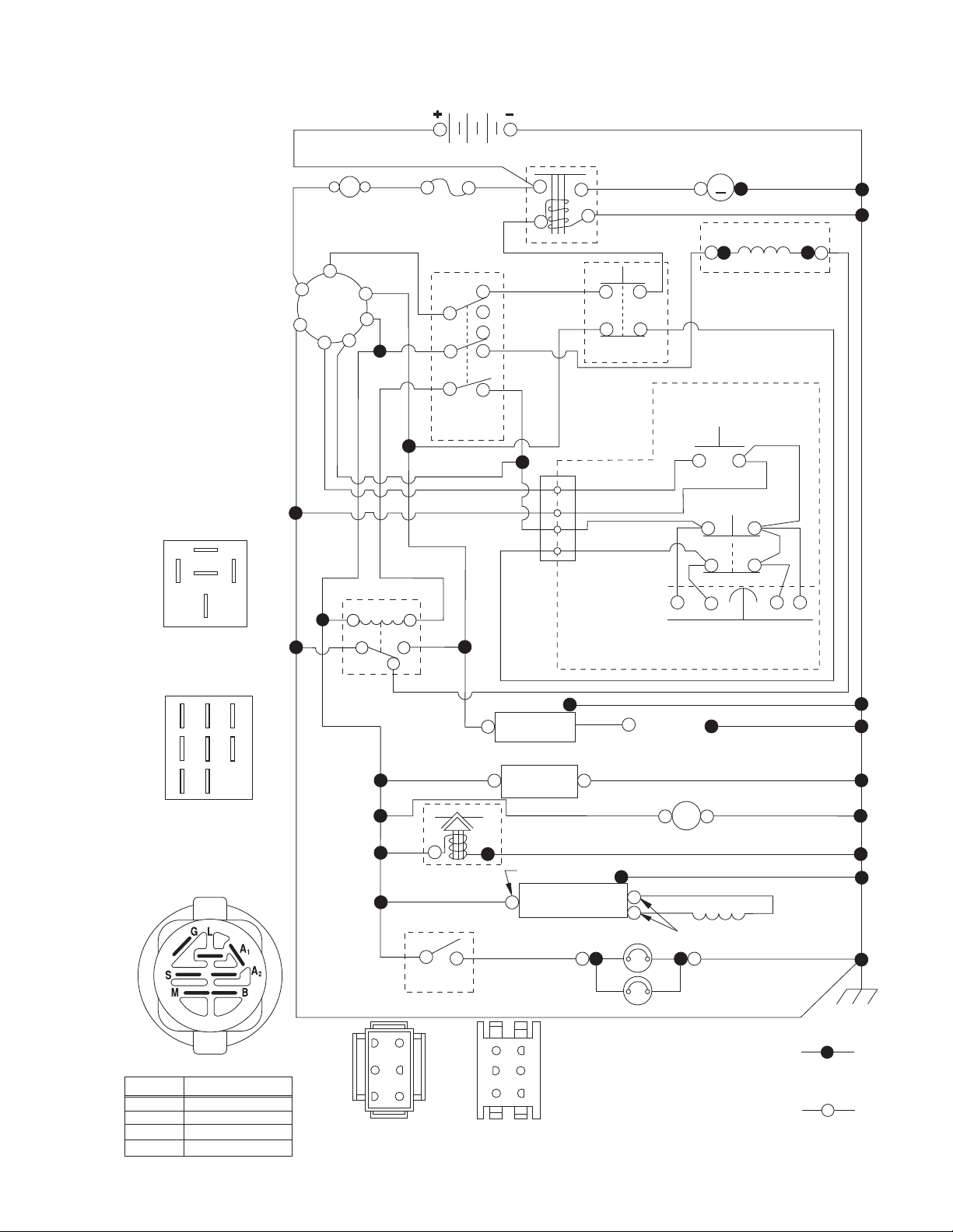
TRACTOR - MODEL NO. YTA1946 (96048005500), PRODUCT NO. 960 48 00-55
SCHEMATIC
SCH13
87
87A
30
RELAY
BATTERY
(OPTIONAL)
B
G
L
A
AMMETER
S
M
A1
A2
BLUE
WHITE
BLACK
BLUE
RED
C
A
B
BLACK
FUSE
PTO SWITCH
(DISENGAGED)
BLACK
BLACK
BLACK
8586
85 86
30
87A
87
BLACK
BLACK /WHITE
RED
H
D
E
WHITE
RED
BLACK
SOLENOID
2
3
1
6
JUNCTION
CONNECTOR
CHASSIS
HARNESS
BLACK
WHITE
CLUTCH/BRAKE
(PEDAL UP)
BLACK
BLACK
BLACKBLACK
GRAY
STARTER
M
M
ELECTRIC CLUTCH
GRAY
REVERSE SWITCH
(NOT IN REVERSE)
SEAT SWITCH
(NOT OCCUPIED)
SHORTING
CONNECTOR
BLACK
NOTES
IGNITION SWITCH
OFF
RUN/OVERRIDE
RUN
START
H
FC
B
A
E
D
G
PTO SWITCH
(MATING SIDE)
CIRCUITPOSITION
M+G+A1
B+A1
B+A1
B+S+A1
“MAKE”
L+A2
BLACK
BLUE
ORANGE
SWITCH
3
6
52
41
CHASSIS HARNESS
CONNECTOR
(MATING SIDE)
BLUE
FUEL
LINE
FUEL SHUT-OFF
SOLENOID
(IF EQUIPPED)
RED
LIGHT
DASH HARNESS
CONNECTOR
3
IGNITION
UNIT
(OPTIONAL)
HOUR
METER
BLUE
CHARGING SYSTEM OUTPUT
9-15 AMP DC @ 3600 RPM
REGULATOR
BROWN
6
3
5
2
1
4
SPARK
PLUGS GAP
(2 PLUGS ON
TWIN CYL. ENGINES)
BLACK
12V
POWER OUTLET
(OPTIONAL)
STATOR
28 VOLTS AC @ 3600 RPM (REGULATOR DISCONNECTED)
HEADLIGHTS
BLACK
BLACK
WIRING INSULATED CLIPS
IF WIRING INSULATED
NOTE:
CLIPS WERE REMOVED FOR
SERVICING OF UNIT, THEY
SHOULD BE RE-INSTALLED TO
PROPERLY SECURE YOUR
WIRING.
NON-REMOVABLE
CONNECTIONS
REMOVABLE
CONNECTIONS
Page 4
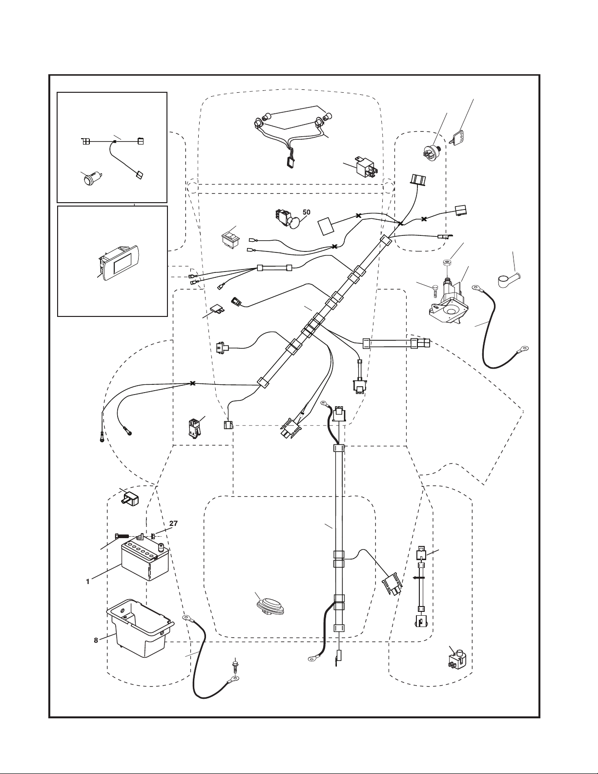
TRACTOR - MODEL NO. YTA1946 (96048005500), PRODUCT NO. 960 48 00-55
ELECTRICAL
T21S
With 12V Outlet Option
103
59
With Service Minder Option
4646
26
34
79
40
22
21
81
41
30
27
33
42
43
25
16
90
71
2
29
28
55
102
105
4
Page 5

TRACTOR - MODEL NO. YTA1946 (96048005500), PRODUCT NO. 960 48 00-55
ELECTRICAL
KEY PART
NO. NO. DESCRIPTION
1 532 16 34-65 Battery
2 874 76 04-12 Bolt Hex Head 1/4-20 x 3/4
8 532 19 32-28 Box Battery
16 532 17 61-38 Switch Interlock Push-In
21 532 40 02-52 Harness Socket Light w/4152J
22 532 00 41-52 Bulb Light
25 585 55 55-01 Cable Starter
26 532 17 51-58 Fuse
27 873 51 04-00 Nut Keps Hex 1/4-20 unc
28 532 42 16-86 Cable, Ground
29 532 40 15-45 Switch, Seat
30 532 19 33-50 Switch, Ign
33 532 41 19-35 Key/Chain
34 532 11 07-12 Switch Light/Reset
40 581 02 28-01 Harness Ign. Dash
41 817 72 04-08 Screw Thd Cut 1/4-20 x 1/2
42 532 13 15-63 Cover, Terminal
43 532 19 25-07 Solenoid
46 532 40 17-63 Gauge Serviceminder Hrmtr
50 532 17 46-51 Switch PTO 8 Terminal
55 817 06 05-12 Screw Thdrol 5/16-18 x 3/4 TYTT
71 532 44 15-44 Harness Ign. Chassis
79 532 17 52-42 Socket Asm. Bulb
81 532 40 96-15 Relay Harness Sealed
90 532 43 53-95 Cover Terminal
102 581 02 34-01 Harness Pigtail
105 532 40 75-68 Switch Reverse
NOTE: All component dimensions given in U.S. inches
1 inch = 25.4 mm
5
Page 6
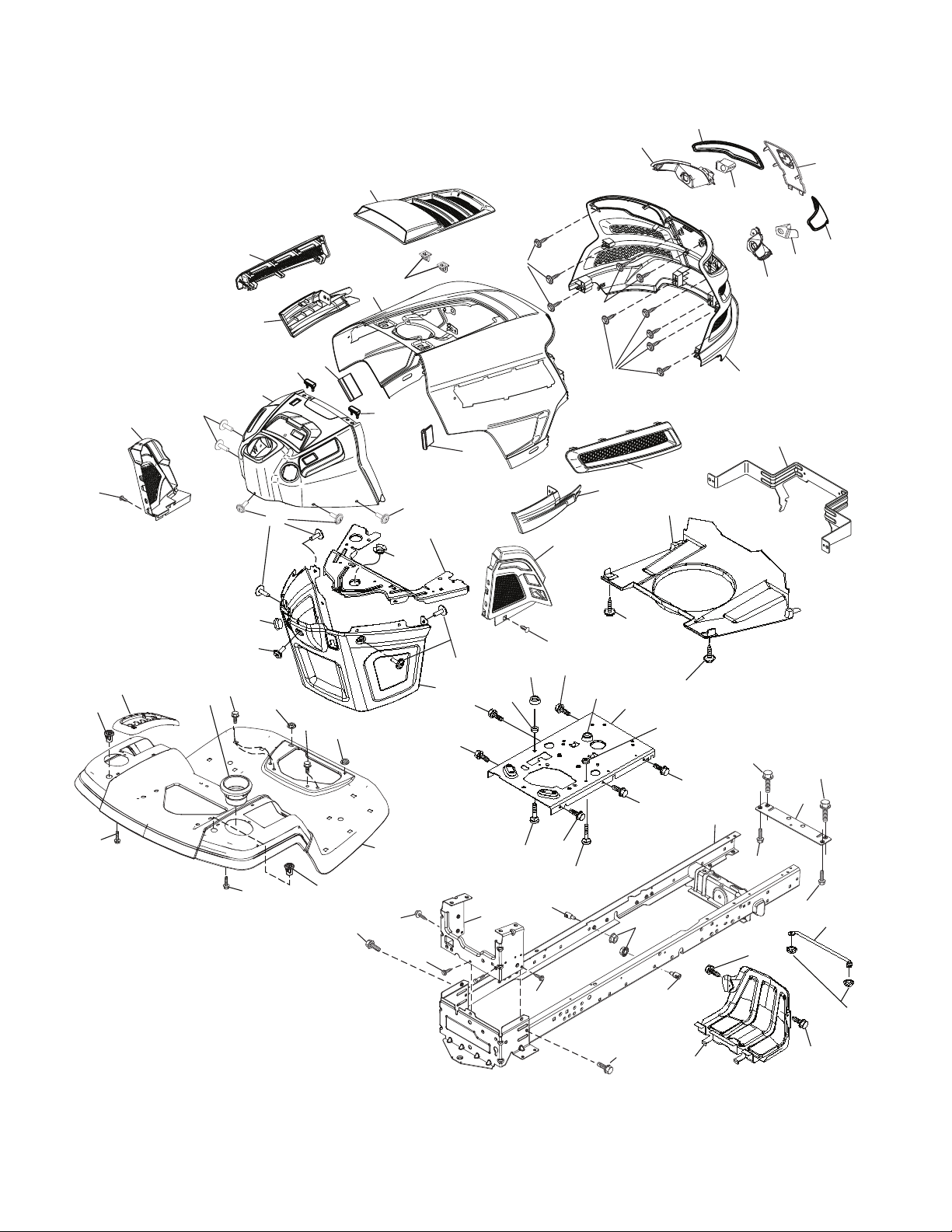
TRACTOR - MODEL NO. YTA1946 (96048005500), PRODUCT NO. 960 48 00-55
CHASSIS
15
208
3
204
297
350
181
336
196
176
138
36
203
206
195
176
5
176
194
137
36
234
194
14
214
137
176
177
175
182
68
176
68
234
130
236
235
335
350
68
130
235
130
205
34
130
202
68
150
130
236
68
25
191
207
18
151
213
213
218
180
287
chassis-tex_GT HUSQ_II_160
162
181
159
37
189
189
68
58
183
228
189
183
159
194
228
152
68
68
217
159
52
159
6
Page 7

TRACTOR - MODEL NO. YTA1946 (96048005500), PRODUCT NO. 960 48 00-55
CHASSIS
KEY PART
NO. NO. DESCRIPTION
3 532 44 44-81 Applique Sub Asm.
5 581 46 69-03 Dash
14 532 44 11-77 Hood
15 532 43 97-33 Lens LH
18 532 44 06-53 Grille
25 532 44 33-85 Lens RH
34 580 91 08-01 Plate Engine
36 817 06 05-12 Screw 5/16-18 x 3/4
37 532 44 12-06 Fender
52 873 68 05-00 Nut Lock 5/16-18
58 532 41 22-80 Drawbar Upper
68 817 49 05-08 Screw Thdrol 5/16-18 x 1/2
130 532 41 63-58 Screw #10 x 0.750
137 532 40 75-90 Bumper Dash
138 532 43 97-47 Cupholder
150 532 43 99-21 Air Duct
151 532 43 66-70 Bracket Pivot
152 532 43 98-70 Shield Browning
159 817 00 06-12 Screw Hexwsh Thrd 3/8-16 x 3/4
162 532 14 24-32 Screw
175 532 19 63-04 Crossmember
176 532 40 07-76 Screw 10-24 x 5/8
177 532 19 52-27 Bushing Steering
180 532 41 50-63 Chassis
181 532 43 97-46 Bushing
182 532 40 68-59 Dash Lower
183 874 52 05-20 Bolt 5/16-18 x 1-1/4
189 817 00 05-12 Screw 5/16-18 x 3/4
KEY PART
NO. NO. DESCRIPTION
191 532 43 74-55 Insert Reflective RH
194 873 90 05-00 Nut Lock Hex Flange 5/16-18
195 532 40 41-37 Plug Hole Dash Lower
196 532 43 96-47 Console Asm. Deck Lift
202 532 43 97-28 Vent Side Hood RH
203 532 43 97-27 Vent Side Hood LH
204 532 43 57-14 Vent Top Hood
205 532 43 97-30 Trim Hood Side RH
206 532 43 97-29 Trim Hood Side LH
207 532 43 97-34 Bezel RH
208 532 43 97-35 Bezel LH
213 874 76 05-12 Bolt 5/16-18 x 3/4
214 532 19 91-45 Clip Retainer Tinner
217 532 40 91-67 Rod Pivot
218 532 19 63-95 X-Piece Hood Stop
228 532 19 51-61 Stud Fastner
234 532 40 47-42 Bumper Hood
235 532 40 61-29 Spacer Fender
236 873 93 05-00 Nut Lock 5/16-18 unc
287 817 60 04-06 Screw 1/4-20 x 3/8
297 532 43 74-56 Insert Reflective LH
335 532 44 82-04 Cover RH
336 532 44 53-09 Cover LH
350 532 44 51-43 Clip X-mas Tree
- - 532 40 09-44 Bumper
NOTE: All component dimensions given in U.S. inches
1 inch = 25.4 mm
7
Page 8
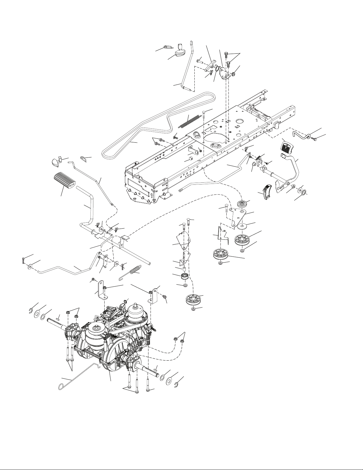
TRACTOR - MODEL NO. YTA1946 (96048005500), PRODUCT NO. 960 48 00-55
DRIVE
207
221
213
160
209
206
92
26
125
376
306
161
185
197
345
143
184
221
56
35
195
6
51
163
160
125
211
215
42
15
64
203
160
188
29
125
374
125
167
160
159
67
116
17
172
5
299
300
373
302
375
303
49
190
51
186
189
187
51
52
214
377
278
50
210
222
211
166
196
172
33
37
205
2
99
116
73
378
125
116
2
205
37
33
1
73
282
301
51
drive-tex_VATR_PEDAL_36
8
Page 9

TRACTOR - MODEL NO. YTA1946 (96048005500), PRODUCT NO. 960 48 00-55
DRIVE
KEY PART
NO. NO. DESCRIPTION
1 – – – – – – Transmission, Variator SD Pdeal
(584973901) (Order parts from
transaxle manufacturer.)
2 532 12 35-83 Key Square
5 874 76 06-36 Bolt Hex HS 3/8-16 unc
6 532 12 40-28 Bushing Snap
15 819 13 13-16 Washer 13/32 x 13/16 x 16 Ga.
17 584 95 40-01 Spring Brake
26 532 19 96-79 Spring Return Cruise
29 584 82 31-01 Rod Brake
33 812 00 00-01 E-Ring
35 583 86 45-01 Rod Brake Parking
37 532 18 89-67 Washer Harden .793 x 1.637 x 060
42 532 12 48-72 Cover Pedal Blk Round
49 872 11 06-14 Bolt Rdhd 3/8-16unc x1-3/4 Gr.5
50 532 19 43-27 Idler.Flat
51 873 90 06-00 Nut Hex Flangelock 3/8-16
52 532 19 43-26 Idler V-Groove Offset
56 532 19 72-53 Belt Drive
64 532 44 83-53 Shaft Asm. Pedal Brake
67 819 13 13-12 Washer 13/32 x 13/16 x 12 Ga.
73 874 49 05-44 Bolt Hex Flghd 5/16-18 Gr. 5
92 874 76 05-20 Bolt
99 532 43 59-35 Rod Bypass
116 873 90 05-00 Nut Lock Hex Flange 5/16-18 unc
125 817 00 05-12 Screw 5/16-18 x 3/4 Smgml Tap/Bl
143 817 49 05-08 Screw Thdrol 5/16-18 x 1/2 Tytt
159 876 02 04-12 Pin Cotter 1/8 x 3/4
160 532 16 94-84 Retainer Clip(M) Dia. 290
161 532 10 57-09 Spring Return Clutch 6.75
163 583 97 13-01 Rod Control Pedal
166 532 42 91-64 Nut Push .625
167 532 40 52-57 Latch Brake Parking
172 583 97 42-01 Strap Torque LH/RH
184 532 44 14-55 Handle Parking Brake
185 872 11 06-22 Bolt Rdhd 3/8-16 unc x 2-3/4 Gr.5
186 532 19 43-21 Spacer Retainer
187 819 13 32-10 Washer 13/32 x 2 x 10 Ga.
KEY PART
NO. NO. DESCRIPTION
188 532 19 43-23 Link Clutch Ground Drive
189 532 19 43-17 Bellcrank Groundrive Nstg/Nstl
190 532 19 43-18 Keeper Bellcrank Drive Ground
195 581 50 46-01 Brake Bracket
196 817 00 06-16 Screw 3/8-16 x 1
197 532 19 58-04 Link Clutch Anti-Rotation
203 819 11 11-16 Washer 11/32 x 11/16 x 16 Ga.
205 532 12 17-48 Washer 25/32 x 1-5/8 x 16 Ga.
206 532 44 85-96 Bracket Mount Latch Cruise
207 532 44 82-64 Latch Control Cruise
209 532 19 95-92 Rod Control Cruise
210 532 44 82-70 Weldment Pedal
211 532 12 01-83 Bearing Nylon
213 532 40 31-19 Knob Control Cruise
214 532 42 12-63 Pedal Forward Pad
215 532 44 82-54 Cap Pedal Reverse
221 532 40 31-87 Retainer Spring Clip Handle
222 879 21 20-10 Washer 21/32 x 1-1/4 10 Ga.
278 580 36 91-01 Bolt Cruise Variator
282 874 49 05-48 Screw Thdrol 5/16-18 x 3
299 532 41 56-83 Bracket Mount Idler
300 532 41 56-81 Keeper Idler Rear
301 532 41 56-80 Pulley Idler V-Groove
302 581 42 05-01 Pulley Idler Flat 2.0 Od
303 872 11 06-18 Bolt Rdhd Sgnk 3/8-16 x 2-1/4
306 876 02 04-16 Cotter Pin
345 872 11 06-06 Bolt Rdhd Sgnk 3/8-16 x 1 Gr. 5
373 581 46 18-01 Spacer Idler
374 581 47 52-01 Bracket Brake Arm
375 873 68 06-00 Nut Crownlock 3/8-16 unc
376 532 42 65-89 Nut Flange
377 584 30 34-01 Gear Sector
378 584 28 77-01 Nut Push 8 mm
NOTE: All component dimensions given in U.S. inches
1 inch = 25.4 mm
9
Page 10
TRACTOR - MODEL NO. YTA1946 (96048005500), PRODUCT NO. 960 48 00-55
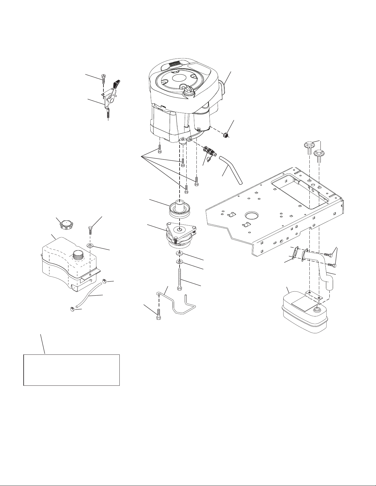
ENGINE
1
21
20
45
87
84
82
81
12
18
15
37
29
OPTIONAL EQUIPMENT
Spark Arrester
97
28
96
37
90
11
79
41
42
9
85
69
94
2
engine-tex_BS_89
10
Page 11

TRACTOR - MODEL NO. YTA1946 (96048005500), PRODUCT NO. 960 48 00-55
ENGINE
KEY PART
NO. NO. DESCRIPTION
1 – – – – – – Engine B&S Model No. 33S877-
0009-G1 (586190501) (Order parts
from engine manufacturer.)
2 532 44 67-60 Muffler
9 532 19 43-19 Keeper Belt Engine
11 532 40 00-08 Clutch Electric
12 532 40 29-80 Pulley Engine
15 581 29 01-01 Tank Fuel
18 532 43 02-20 Cap Asm
20 532 40 15-08 Control Throttle
21 532 41 63-58 Screw # 10 x 0.750
28 532 13 70-40 Fuel Line
29 532 13 71-80 Spark Arrester Kit
37 532 12 34-87 Clamp Hose
41 532 12 61-97 Washer 1-1/2 OD x 15/32 ID x .250
42 810 04 07-00 Washer Lock 7/16
45 873 51 04-00 Nut Keps Hex 1/4-20 unc
69 532 16 52-91 Gasket
79 532 19 23-34 Screw Socket Hd. 5/16-18 x .75
81 532 14 84-56 Easy Oil Drain Tube
82 532 42 82-87 Oil Drain Valve
84 817 06 06-20 Screw 3/8-16 x 1-1/4
85 532 17 39-37 Bolt Hex 7/16-20 x 4 x Gr. 5-1.5 Thr
87 537 17 18-77 Bolt 5/16-18 unc x 3/4 w/Sems
90 817 00 06-16 Screw 3/8-16 x 1
94 581 88 09-01 Tube Exhaust
96 819 09 14-16 Washer 9/32 x 7/8 x 16 Ga.
97 817 67 04-12 Screw Hexwsh Thdrol 1/4-20 x 3/4
NOTE: All component dimensions given in U.S. inches
1 inch = 25.4 mm
For engine service and replacement parts, call the toll free
number for your engine manufacturer listed below:
Briggs & Stratton 1-800-233-3723
Engine Power Rating Information
The gross power rating for individual gas engine models is labeled in accordance with SAE (Society of Automotive Engineers) code J1940 (Small Engine Power & Torque Rating Procedure), and rating performance has been obtained and
corrected in accordance with SAE J1995 (Revision 2002-05). Torque values are derived at 3060 RPM; horsepower values
are derived at 3600 RPM. Actual gross engine power will be lower and is affected by, among other things, ambient operating conditions and engine-to-engine variability. Given both the wide array of products on which engines are placed and
the variety of environmental issues applicable to operating the equipment, the gas engine will not develop the rated gross
power when used in a given piece of power equipment (actual “on-site” or net power). This difference is due to a variety
of factors including, but not limited to, accessories (air cleaner, exhaust, charging, cooling, carburetor, fuel pump, etc.),
application limitations, ambient operating conditions (temperature, humidity, altitude), and engine-to-engine variability.
Due to manufacturing and capacity limitations, Briggs & Stratton may substitute an engine of higher rated power for this
Series engine.
11
Page 12

TRACTOR - MODEL NO. YTA1946 (96048005500), PRODUCT NO. 960 48 00-55
STEERING ASSEMBLY
26
45
51
1
63
21
57
16
64
28
13
22
69
68
19
60
57
63
122
35
58
61
4
59
122
9
8
7
6
14
15
70
67
2
67
62
14
66
9
7
8
6
5
13
53
15
8
steering-tex_HUSQHR_5
13
12
Page 13

TRACTOR - MODEL NO. YTA1946 (96048005500), PRODUCT NO. 960 48 00-55
STEERING ASSEMBLY
KEY PART
NO. NO. DESCRIPTION
1 532 43 97-40 Wheel, Steering
2 532 19 59-68 Axle Cast Iron
4 532 40 30-87 Spindle Asm., LH
5 532 40 30-88 Spindle Asm., RH
6 532 12 49-31 Washer, Thrust
7 532 12 17-48 Washer 25/32 x 1-5/8 x 16 Ga.
8 812 00 00-29 Ring, Klip #T5304-75
9 532 12 12-32 Cap, Spindle
13 532 12 17-49 Washer 25/32 x 1-1/4 x 16 Ga.
14 810 04 06-00 Washer, Lock Hvy Hlcl Spr 3/8
15 873 54 06-00 Nut, Crown Lock 3/8-24 unf
16 532 40 82-19 Shaft Steering
19 532 19 47-29 Plate Steering
21 532 18 67-37 Adapter, Wheel Steering
22 532 42 05-37 Steering Support
26 532 43 97-43 Insert, Wheel Steering
28 817 00 06-12 Screw 3/8-16 x 3/4
35 532 19 47-32 Gear, Sector Plate
45 819 18 38-12 Washer 9/16 ID x 2-3/8 OD 12 Ga.
51 873 94 08-00 Nut Hex Jam Toplock 1/2-20 unf
53 532 18 89-67 Washer Hardened .793 x 1.637 x .060
57 532 40 74-65 Bracket Upstop
58 532 19 47-47 Bolt Shoulder Sector Pivot CFM
59 532 19 47-48 Washer Thrust Sector Steering
60 873 97 10-00 Nut Flange Lock 5/8-11
61 532 19 47-40 Draglink, LH
62 532 19 47-41 Draglink, RH
63 817 00 05-12 Screw 5/16-18 x 3/4
64 532 19 98-49 Retainer Clip Spring Steering
66 871 02 07-48 Bolt Hex Fghd 7/16-14 x 3 Serr
67 532 19 47-37 Bushing PM Front Axle
68 873 90 07-00 Nut Lock Flange 7/16-14 Gr. 5
69 532 19 91-62 Washer 1.5 x .505 x .118
70 532 19 61-97 Bracket Deck Susp. Front
122 532 44 49-62 Cap Gear
NOTE: All component dimensions given in U.S. inches
1 inch = 25.4 mm
13
Page 14

TRACTOR - MODEL NO. YTA1946 (96048005500), PRODUCT NO. 960 48 00-55
55
147
32
31
33
56
34
57
59
240
197
188
1
69
69
69
199
40
145
46-tex_elect_10
15
14
13
11
8
21
25
26
27
198
29
21
21
23
24
36
40
19
19
6
117
116
40
119
117
119
116
40
68
189
189
188
21
21
69
69
4
21
3
46
2
46
200
30
30
242
241
256
257
257
261
257
257
262
256
MOWER DECK
14
Page 15

TRACTOR - MODEL NO. YTA1946 (96048005500), PRODUCT NO. 960 48 00-55
MOWER DECK
KEY PART
NO. NO. DESCRIPTION
1 583 90 09-05 Mower Housing
2 532 40 55-06 Cover Mandrel RH
3 532 40 55-07 Cover Mandrel LH
4 874 76 05-12 Bolt Hex Hd 5/16-18 unc x 3/4
6 532 19 51-86 Arm Suspension
8 532 19 30-03 Bolt/Washer asm 7/16-20 unf
11 532 40 53-80 Blade Mower Hi Lift
13 532 19 28-72 Shaft Assembly, Mandrel
14 532 18 72-81 Housing, Mandrel
15 532 11 04-85 Bearing, Ball, Mandrel
19 532 19 65-39 Bolt, Shoulder
21 873 68 05-00 Nut
23 532 19 25-57 Bracket, Deflector
24 532 10 53-04 Cap, Sleeve
25 532 19 70-26 Spring, Torsion, Deflector
26 532 11 04-52 Nut, Push
27 532 40 53-57 Shield, Deflector
29 532 13 14-91 Rod, Hinge
30 532 17 39-84 Screw Thdrol Rolling Wsh Hd
31 532 18 76-90 Washer, Spacer
32 532 19 74-73 Pulley, Mandrel
33 532 40 02-34 Nut, Toplock, Flanged
34 872 11 06-12 Bolt Carr Sh. 3/8-16 x 1-1/2 Gr. 5
36 532 19 73-79 Pulley, Idler, Flat
40 873 90 06-00 Nut, Lock Flg. 3/8-16 unc
46 532 13 77-29 Screw
55 532 19 72-49 Arm, Idler
56 532 19 90-92 Spacer, Retainer
57 817 00 06-16 Screw Hexwsh Thd 3/8-16 x 1
59 532 14 10-43 Guard, Tuv Idler (94)
KEY PART
NO. NO. DESCRIPTION
68 532 40 51-43 V-Belt
69 872 14 05-05 Bolt
116 532 19 34-06 Bolt, Shoulder
117 532 17 48-73 Wheel, Gauge
119 819 13 20-12 Washer 13/32 x 1-1/4 x 12 Ga.
145 532 19 31-97 Pulley Idler
147 532 19 72-51 Spring Mower Drive
188 532 19 51-61 Stud Fastener
189 873 90 05-00 Nut Lock Hex Flange
197 819 13 13-12 Washer 13/32 x 13/16 x 12 Ga.
198 532 40 31-49 Baffle Center Front
199 532 40 31-50 Baffle Front RH
200 532 41 35-24 Washer 13/32 x 1 x 1/2 11 Ga.
240 874 52 06-36 Bolt 3/8-16 unc x 2-1/4 Gr. 5
241 532 15 29-27 Screw
242 532 41 55-98 Washout Port
256 578 29 64-04 Screw Buttonhead 5/16-18
257 873 90 04-00 Nut Hex Flange 1/4-20 unc
261 585 31 77-05 Plate Reinforcement Front
262 585 31 78-05 Plate Reinforcement Side
- - 532 19 28-70 Mandrel Assembly (Includes
housing (key #14), shaft assembly
(key #13), and bearing (key #15)
only - pulley/nut/washer and blade
bolt/washers not included)
- - 586 35 22-01 Replacement Mower, Complete
NOTE: All component dimensions given in U.S. inches
1 inch = 25.4 mm
15
Page 16

TRACTOR - MODEL NO. YTA1946 (96048005500), PRODUCT NO. 960 48 00-55
MOWER LIFT
91
7
87
10
90
89
98
3
97
2
88
97
87
89
lift-tex_32
KEY PART
NO. NO. DESCRIPTION
2 532 42 20-27 Shaft Asm., Lift
3 532 19 52-31 Lever Asm., Lift RH
7 580 96 23-01 Grip, Lever
10 532 19 63-14 Spring Torsion
87 532 19 42-09 Pin Cotter 7/16 Bow Tie Lock
88 532 41 07-10 Spring Lift Assist
89 819 19 19-12 Washer Clear Zinc
90 532 19 42-08 Pin Cotter 5/16 Bow Tie Lock
91
89
87
KEY PART
NO. NO. DESCRIPTION
91 532 19 79-84 Link Lift Susp Mower Rear
97 817 00 06-12 Screw 3/8-16 x .75 Smgml Tap/R.Z
98 532 42 05-25 Link Lift Susp. Front Mower
NOTE: All component dimensions given in U.S. inches
1 inch = 25.4 mm
16
Page 17

TRACTOR - MODEL NO. YTA1946 (96048005500), PRODUCT NO. 960 48 00-55
SEAT ASSEMBLY
1
44
41
40
10
21
8
8
8
7
7
8
6
37
6
2
37
43
seat-tex_6.5SL_3
KEY PART
NO. NO. DESCRIPTION
1 532 43 98-22 Seat
2 532 18 01-66 Bracket Pivot Fender
3 532 14 06-75 Strap, Asm Fender
6 873 80 06-00 Nut, Lock w/Ins. 3/8-16 unc
7 532 12 41-81 Spring, Seat Cprsn
8 532 17 18-77 Bolt 5/16-18 unc x 3/4 w/Sems
10 532 19 69-77 Pan, Seat
21 532 17 18-52 Bolt, Shoulder 5/16-18
21
3
KEY PART
NO. NO. DESCRIPTION
37 873 80 05-00 Nut, Lock 5/16-18 unc
40 532 19 76-61 Handle Slide Seat
41 532 19 82-00 Spring Latch Seat
43 874 76 06-12 Bolt Fin Hex 3/8-16 unc x 3/4
44 819 13 38-12 Washer 13/32 x 2-3/8 x 12 Ga.
NOTE: All component dimensions given in U.S. inches
1 inch = 25.4 mm
17
Page 18

TRACTOR - MODEL NO. YTA1946 (96048005500), PRODUCT NO. 960 48 00-55
6
2
1
3
11
4
10
5
9
8
7
wheel_art_1-tex
DECALS
2 5
8
6
3
4
12
10
2
9
1
7
KEY PART
NO. NO. DESCRIPTION
1 581 57 90-01 Decal, Fender Warning
2 581 62 73-01 Decal, Hood
3 586 30 66-01 Decal, Hood Panel SD
4 581 57 95-01 Decal, Mower
5 532 42 38-29 Decal, Customer Respons.
6 586 06 55-01 Decal, Replacement
7 581 57 99-01 Decal, Warning Spark.
8 585 91 46-01 Decal, Engine
KEY PART
NO. NO. DESCRIPTION
10 585 71 44-02 Decal, POP Armor Prot. Deck
12 581 58 00-01 Decal, Mower V-Belt Schematic
- - 581 72 48-01 Decal, Bypass
- - 532 43 96-81 Pad, Footrest, LH
- - 532 43 96-82 Pad, Footrest, RH
- - 586 26 35-96 Manual, Operator's
(English/French)
- - 586 26 35-49 Manual, Parts (English/French)
9 532 14 50-05 Decal, Battery Dnge/Poi
WHEELS AND TIRES
KEY PART
NO. NO. DESCRIPTION
1 532 05 91-92 Cap Valve Tire
2 532 06 51-39 Stem Valve
3 532 13 83-36 Rim Front
4 532 05 99-04 Tube Front (Service Item Only)
5 532 10 62-22 Tire Front 15 x 6-6
6 532 12 49-57 Fitting Grease (Front Wheel Only)
7 532 12 49-59 Bearing Flange (Front Wheel Only)
8 532 17 50-39 Cap Axle Blk 1 50 x 1 00
9 532 13 84-68 Tire Rear 20 x 8-8
10 532 12 49-26 Tube Rear (Service Item Only)
11 532 13 83-37 Rim Asm 8" Rear
- - 532 14 43-34 Sealant, Tire (10 oz. Tube)
NOTE: All component dimensions given in U.S. inches
1 inch = 25.4 mm
18
Page 19

TRACTEUR - NO. DE MODÈLE YTA1946 (96048005500), NO. DE PROD. 960 48 00-55
SCHÉMA
SCH13-F
87
87A
RELAIS
30
A
ROUGE
BLANCHE
ROUGE
BLANCHE
NOIR
M
M
EMBRAYAGE
ÉLECTRIQUE
NOIR
PRISE DE FORCE
S
M
B
A1
G
A2
L
BLU
NOIR
BLU
NOIR
(DÉGAGÉE)
C
A
B
NOIR
NOIR
NOIR
H
D
E
BLANCHE
ROUGE
NOIR
2
3
1
6
JONCTION
CONNECTEUR
NOIR
NOIR
NOIRNOIR
GRIS
GRIS
8586
85 86
30
87A
87
NOIR
NOIR/BLANCHE
Châssis
CONNECTEUR
H
FC
B
A
PRISE DE FORCE
INTERRUPTEUR
(ACCOUPLER CÔTÉ)
E
D
G
NOTES
CONTACTEUR D'ALLUMAGE
ARRÊT
MARCHE/
ALLUMAGE
MARCHE
CIRCUITPOSITION
M + G + A1
B + A1
B + A1
“FAITS”
L+A2
NOIR
BLU
BLU
(Si Équipé)
ROUGE
ORANGE
INTERRUPTEUR LUMIÈRE
3
6
52
41
19
CHARGINGSYSTEMOUTPUT
9-16 AMPDC@3600RPM
RÉGULATEUR
BRUN
6
3
5
2
1
4
NOIR
BLU
PHARES
12V
exutoire
(FACULTATIF)
STATOR
28 VOLTS CA MIN. @ 3600 T/M (LE
SYSTÈME DE CHARGE EST DÉBRANCHÉ)
PINCES ISOLÉES
REMARQUE: SI LES PINCES
ISOLÉES ONT ÉTÉ ENLEVÉES
POUR L'ENTRETIEN DU MODÈLE,
NOIR
NOIR
CONNECTEURS
NON-AMOVIBLES
CONNECTEURS
Page 20

TRACTEUR - NO. DE MODÈLE YTA1946 (96048005500), NO. DE PROD. 960 48 00-55
ÉLECTRIQUE
T21S-F
Avec 12v exutoire l'option
103
59
Avec l'indicateur d'heures l'option
4646
26
34
79
40
22
21
81
41
30
27
33
42
43
25
16
90
71
2
29
28
55
102
105
20
Page 21

TRACTEUR - NO. DE MODÈLE YTA1946 (96048005500), NO. DE PROD. 960 48 00-55
ÉLECTRIQUE
NO. NO
DE DE
RÉF. PIÈCE DESCRIPTION
1 532 16 34-65 Batterie
2 874 76 04-12 Boulon H 1/4-20 unc x 3/4
8 532 19 32-28 Bac de batterie
16 532 17 61-38 Interrupteur de verrouillage pressé
21 532 40 02-52 Harnais des prises de courant des phares avec 4152J
22 532 00 41-52 Ampoule N°1156
25 585 55 55-01 Câble de batterie
26 532 17 51-58 Fusible
27 873 51 04-00 Écrou H 1/4-20 unc
28 532 42 16-86 Câble de masse
29 532 40 15-45 Interrupteur
30 532 19 33-50 Contacteur d’allumage
33 532 41 19-35 Clé/chaîne
34 532 11 07-12 L'interrupteur des phares
40 581 02 28-01 Harnais des câbles d’allumage
41 817 72 04-08 Vis 1/4-20 x 1/2
42 532 13 15-63 Couverture de borne
43 532 19 25-07 Solénoïde
46 532 40 17-63 Jauge
50 532 17 46-51 Interrupteur PTO
55 817 06 05-12 Vis 5/16-18 x 3/4 TYTT
71 532 44 15-44 Harnais des cables of d'allumage
79 532 17 52-42 Prise de courant d’ampoule
81 532 40 96-15 Harnais
90 532 43 53-95 Couverture
102 581 02 34-01 Harnais
105 532 40 75-68 Interrupteur
REMARQUE: Toutes les dimensions de composant sont données en pouces É.-U. --1 pouce = 25,4 mm
21
Page 22

TRACTEUR - NO. DE MODÈLE YTA1946 (96048005500), NO. DE PROD. 960 48 00-55
CHÂSSIS/ENCEINTES
15
208
3
204
297
350
181
287
336
196
176
138
36
203
206
195
176
162
5
176
194
137
36
234
181
194
159
14
214
137
37
189
177
176
189
175
182
68
176
68
234
58
130
236
183
235
68
228
335
350
183
68
130
235
130
205
34
130
194
68
202
150
130
236
68
25
191
207
18
151
213
213
218
180
68
68
217
159
chassis-tex_GT HUSQ_II_160
22
189
159
228
152
52
159
Page 23

TRACTEUR - NO. DE MODÈLE YTA1946 (96048005500), NO. DE PROD. 960 48 00-55
CHÂSSIS/ENCEINTES
NO. NO
DE DE
RÉF. PIÈCE DESCRIPTION
3 532 44 44-81 Applique
5 581 46 69-03 Tableau de bord, Husq.
14 532 44 11-77 Capot
15 532 43 97-33 Lentille C.G.
18 532 44 06-53 Calandre
25 532 44 33-85 Lentille C.D.
34 580 91 08-01 Plaquette de moteur
36 817 06 05-12 Vis 5/16-18 x 3/4
37 532 44 12-06 Aile
52 873 68 05-00 Ecrou auto-bloquant 5/16-18
58 532 41 22-80 La Barre D'attelage
68 817 49 05-08 Vis 5/16-18 x 1/2
130 532 41 63-58 Vis #10 x 0.750
137 532 40 75-90 Tableau de bord du chocs
138 532 43 97-47 Tenante de tasse
150 532 43 99-21 Conduit d'air
151 532 43 66-70 Soutien du support
152 532 43 98-70 Déflecteur
159 817 00 06-12 Vis 3/8-16 x 3/4
162 532 14 24-32 Vis
175 532 19 63-04 Croix
176 532 40 07-76 Vis 10-24 x 5/8
177 532 19 52-27 Direction De Douille
180 532 41 50-63 Châssis
181 532 43 97-46 Douille
182 532 40 68-59 Inférieur du tableau de bord
183 874 52 05-20 Boulon H 5/16-18 x 1-1/4
189 817 00 05-12 Vis 5/16-18 x 3/4
191 532 43 74-55 Insert (C,D)
NO. NO
DE DE
RÉF. PIÈCE DESCRIPTION
194 873 90 05-00 Écrou frein H 5/16-18
195 532 40 41-37 Bouchon
196 532 43 96-47 Panneau
202 532 43 97-28 Ventilé C.D.
203 532 43 97-27 Ventilé C.G.
204 532 43 57-14 Ventilé supérieur
205 532 43 97-30 Jupe C.D.
206 532 43 97-29 Jupe C.G.
207 532 43 97-34 Biseau C.D.
208 532 43 97-35 Biseau C.G.
213 874 76 05-12 Boulon H 5/16-18 unc x 3/4
214 532 19 91-45 Pince de arrêtor
217 532 40 91-67 Attache
218 532 19 63-95 Support du capuchon
228 532 19 51-61 Tenon
234 532 40 47-42 Capot/pare-chocs
235 532 40 61-29 Entretoise pour l’aile
236 873 93 05-00 Écrou auto-bloquant 5/16-18 unc
287 817 60 04-06 Vis 1/4-20 x 3/8
297 532 43 74-56 Insert C.G
335 532 44 82-04 Couvercle C.D.
336 532 44 53-09 Couvercle C.G.
350 532 44 51-43 Attache
- - 532 40 09-44 Pare-chocs
REMARQUE: Toutes les dimensions de composant sont données en pouces É.-U. --1 pouce = 25,4 mm
23
Page 24

TRACTEUR - NO. DE MODÈLE YTA1946 (96048005500), NO. DE PROD. 960 48 00-55
ENTRAÎNMENT
207
221
213
160
209
206
92
26
125
376
306
161
185
197
345
143
184
221
56
35
195
6
51
163
160
125
211
215
42
15
64
203
160
188
29
125
374
125
167
160
159
67
116
17
172
5
299
300
373
302
375
303
49
190
51
186
189
187
51
52
214
377
278
50
210
222
211
166
196
172
33
37
205
2
99
116
73
378
125
116
2
205
37
33
1
73
282
301
51
drive-tex_VATR_PEDAL_36
24
Page 25

TRACTEUR - NO. DE MODÈLE YTA1946 (96048005500), NO. DE PROD. 960 48 00-55
ENTRAÎNMENT
NO. NO
DE DE
RÉF. PIÈCE DESCRIPTION
1 – – – – – – Transmission Variator SD
(584973901) (Commandez les pièces
du fabricant du transmission.)
2 532 12 35-83 Clé
5 874 76 06-36 Boulon HS 3/8-16 unc
6 532 12 40-28 Coussinet
15 819 13 13-16 Rondelle 13/32 x 13/16 x 16 Ja.
17 532 41 36-78 Ressort
26 532 19 96-79 Ressort de rappel
29 532 40 38-06 Tige du frein
33 812 00 00-01 Bague en E
35 532 43 54-86 Tige du frein de stationnement
37 532 18 89-67 Rondelle .793 x 1.637 x 060
42 532 12 48-72 Couverture de la pédale
49 872 11 06-14 Boulon
50 532 19 43-27 Poulie du galet-tendeur
51 873 90 06-00 Écrou frein 3/8-16
52 532 19 43-26 Galet-tendeur
56 532 13 09-69 Courroie trapézoïdale
64 532 19 78-65 Ensemble de l’arbre
67 819 13 13-12 Rondelle 13/32 x 13/16 x 12 Ja.
73 874 49 05-40 Boulon 5/16-18 x 2 1/2 Cat. 5
80 532 44 06-19 Couple De Courroie
92 874 76 05-20 Boulon 5/16-18 unc x 1.25
99 532 41 57-42 Tige de dérivation
116 873 90 05-00 Écrou frein 5/16-18
125 817 00 05-12 Vis 5/16-18 x 3/4
143 817 49 05-08 Vis 5/16-18 x 1/2
153 532 12 47-88 Ressort D’Arrêtoir
159 876 02 04-12 Goupille fendue 1/8 x 3/4
160 532 16 94-84 Collier de retenue
161 532 10 57-09 Ressort de rappel d’embrayage
163 532 44 82-75 Tige du contrôle
166 532 42 91-64 Écrou .625
167 532 40 52-57 Loquet
170 532 19 43-22 Guide-courroie
171 872 11 06-16 Boulon 3/8-16 unc x 2
172 583 97 42-01 Support LH/RH
183 532 13 70-57 Entretoise
184 532 44 14-55 Poignée de frein de stationnement
185 872 11 06-22 Boulon
186 532 19 43-21 Ressort de retenue
187 819 13 32-10 Rondelle
NO. NO
DE DE
RÉF. PIÈCE DESCRIPTION
188 532 19 43-23 Raccord d’embrayage
189 532 19 43-17 Levier coudé
190 532 19 43-18 Garde du courroie
195 581 50 46-01 Frein Support
196 817 00 06-16 Vis 3/8-16 x 1
197 532 19 58-04 Tige
203 819 11 11-16 Rondelle 11/32 x 11/16 x 16 Ja.
205 532 12 17-48 Rondelle 25/32 x 1-5/8 x 16 Ja.
206 532 44 85-96 Support
207 532 19 78-68 Loquet
208 532 19 78-69 Secteur denté
209 532 19 95-92 Tige
210 532 40 09-80 Commande de pédale
211 532 12 01-83 Palier de nylon
213 532 40 31-19 Bouton
214 532 42 12-63 Pédale en avant
215 532 40 17-23 Pédale contraire
216 532 19 61-31 Support (poulie du galet-tendeur)
221 532 40 31-87 Ressort de retenue
222 879 21 20-10 Rondelle 21/32 x 1-1/4 10 Ja.
225 532 40 33-19 Garde du courroie
226 532 40 15-64 Support
227 817 49 05-12 Vis 5/16-18 x 3/4
230 532 18 89-67 Rondelle .793 x 1.637 x 060
278 580 36 91-01 Boulon
282 874 49 05-48 Boulon 5/16-18 x 3
299 532 41 56-83 Support
300 532 41 56-81 Guide-Courroie
301 532 41 56-80 Poulie Du Galet-Tendeur
302 581 42 05-01 Poulie Du Galet-Tendeur 2.0 Od
303 872 11 06-18 Boulon 3/8-16 x 2-1/4
306 876 02 04-16 Goupille en épingle à cheveux 1/8 X 1
345 872 11 06-06 Boulon 3/8-16 x 1 Cat. 5
373 581 46 18-01 Entretoise
374 581 47 52-01 Support
375 873 68 06-00 E'crou
376 532 42 65-89 E'crou 5/16 x 18
377 584 30 34-01 Secteur Denté
378 584 28 77-01 Frein E'crou
REMARQUE: Toutes les dimensions de composant sont données en pouces É.-U. --1 pouce = 25,4 mm
25
Page 26

TRACTEUR - NO. DE MODÈLE YTA1946 (96048005500), NO. DE PROD. 960 48 00-55
MOTEUR
1
21
20
45
87
84
82
29
18
15
37
97
28
96
37
90
12
11
81
79
41
42
9
85
69
94
2
OPTIONAL EQUIPMENT
ÉQUIPMENT FACULTATIF
PARA-ÉTINCELLES
Spark Arrester
engine-tex_BS_89
26
Page 27

TRACTEUR - NO. DE MODÈLE YTA1946 (96048005500), NO. DE PROD. 960 48 00-55
MOTEUR
NO. NO
DE DE
RÉF. PIÈCE DESCRIPTION
1 – – – – – – Moteur B&S-No. de modèle 33S877-
2 532 44 67-60 Silencieux
9 532 19 43-19 Guide-courroie du moteur
11 532 40 00-08 Embrayage Électrique
12 532 40 29-80 Poulie de moteur
15 581 29 01-01 Réservoir d'essence
18 532 43 02-20 Chapeau d'essence
20 532 40 15-08 Commande des gaz
21 532 41 63-58 Vis #10 x 0.750
28 532 13 70-40 Conduite d'essence
29 532 13 71-80 Jeu de pare - étincelles (écran plate)
37 532 12 34-87 Bride de serrage de tuyau
41 532 12 61-97 Rondelle 1-1/2 OD x 15/32 ID x .250
42 810 04 07-00 Rondelle frein 7/16
45 873 51 04-00 Écrou H 1/4-20 unc
69 532 16 52-91 Garniture
79 532 19 23-34 Vis 5/16-18 x .75
81 532 14 84-56 Tube de vidange d'huile
82 532 42 82-87 Soupape d'huile
84 817 06 06-20 Vis 3/8-16 x 1-1/4
85 532 17 39-37 Boulon
87 537 17 18-77 Boulon 5/16-18 UNC x 3/4
90 817 00 06-16 Vis 3/8-16 x 1
94 581 88 09-01 Le tuyau du silencieux
96 819 09 14-16 Rondelle 9/32 x 7/8 x 16 Ja.
97 817 67 04-12 Vis 1/4-20 x 3/4
REMARQUE: Toutes les dimensions de composant sont données en pouce d'E.-U. - - 1 pouce = 25,4 mm.
0009-G1 (586190501) (Commandez les
pièces du fabricant du moteur.)
Pour des pièces de service et de rechange de moteur,
réclamez le numéro de téléphone libre pour votre fabricant de
moteur énuméré ci-dessous:
Briggs & Stratton 1-800-233-3723
Informations concernant la puissance théorique du moteur
La puissance brute pour chaque Modèle de moteur à essence est indiquée conformément au code J1940 (procédure de calcul de
la puissance et du couple des petits moteurs) de la SAE (Society of Automotive Engineers) et les performances théoriques ont été
obtenues et corrigées selon SAE J1995 (révision 2002-05). Les valeurs de couple sont calculées sur la base de 3060tr/min et celles
de puissance sur la base de 3600tr/min. La puissance brute réelle du moteur peut être plus faible notamment à cause des conditions
de fonctionnement et des variations d’un moteur à l’autre. Compte tenu de la grande variété de machines sur lesquelles nos moteurs
sont utilisés et du nombre de problèmes environnementaux applicables au fonctionnement des équipements, il se peut que le moteur
à essence ne développe pas sa puissance théorique une fois qu’il est monté sur une machine particulière (puissance nette ou
réelle «sur site»). Cette différence s’explique par un grand nombre de facteurs, tels que (liste non limitative): accessoires (filtre à air,
échappement, admission, refroidissement, carburateur, pompe à essence, etc.), limites d’utilisation, conditions ambiantes d’utilisation
(température, humidité, altitude) et variations d’un moteur à l’autre. Pour des raisons de fabrication et de capacité limitées, Briggs &
Stratton est susceptible de remplacer ce Modèle par un moteur plus puissant.
27
Page 28

TRACTEUR - NO. DE MODÈLE YTA1946 (96048005500), NO. DE PROD. 960 48 00-55
ENSEMBLE DE LA DIRECTION
26
45
51
1
63
21
57
16
64
28
13
22
69
68
19
60
57
63
122
35
58
61
4
59
122
9
8
7
6
14
15
70
67
2
67
62
14
66
9
7
8
6
5
13
53
15
8
steering-tex_HUSQHR_5
13
28
Page 29

TRACTEUR - NO. DE MODÈLE YTA1946 (96048005500), NO. DE PROD. 960 48 00-55
ENSEMBLE DE LA DIRECTION
NO. NO
DE DE
RÉF. PIÈCE DESCRIPTION
1 532 43 97-40 Volant de direction
2 532 19 59-68 Essieu
4 532 40 30-87 Ensemble de la broche C.G.
5 532 40 30-88 Ensemble de la broche C.D.
6 532 12 49-31 Palier de butée durci
7 532 12 17-48 Rondelle 25/32 x 1-5/8 x 16 Ja.
8 812 00 00-29 Rondelle clip n°t5304-75
9 532 12 12-32 Chapeau de broche
13 532 12 17-49 Rondelle 25/32 x 1-1/4 x 16 Ja.
14 810 04 06-00 Rondelle frein 3/8
15 873 54 06-00 Écrou frein 3/8-24 unf
16 532 40 82-19 Arbre de direction
19 532 19 47-29 Arbre de plaque
21 532 18 67-37 Adaptateur du volant de direction
22 532 42 05-37 Support
26 532 43 97-43 Insert de chapeau du volant de direction
28 817 00 06-12 Vis 3/8-16 x 3/4
35 532 19 47-32 Secteur denté
45 819 18 38-12 Rondelle 9/16 x 2-3/8 x 12 Ja.
51 873 94 08-00 Contre-écrou 1/2-20 unf
53 532 18 89-67 Rondelle .793 x 1.637 x .060
57 532 40 74-65 Support
58 532 19 47-47 Boulon à épualement
59 532 19 47-48 Rondelle
60 873 97 10-00 Écrou frein à collet 5/8-11
61 532 19 47-40 Barre de direction C.G.
62 532 19 47-41 Barre de direction C.D.
63 817 00 05-12 Vis 5/16-18 x 3/4
64 532 19 98-49 Collier de retenue
66 871 02 07-48 Boulon 7/16-14 x 3
67 532 19 47-37 Douille
68 873 90 07-00 Écrou frein à collet 7/16-14 Cat. 5
69 532 19 91-62 Rondelle 1.5 x .505 x .118
70 532 19 61-97 Support
122 532 44 49-62 Chapeau
REMARQUE: Toutes les dimensions de composant sont données en pouces É.-U. --1 pouce = 25,4 mm
29
Page 30

TRACTEUR - NO. DE MODÈLE YTA1946 (96048005500), NO. DE PROD. 960 48 00-55
CARTER DE TONDEUSE
40
145
257
262
256
257
40
119
68
117
21
69
69
21
46
116
21
69
29
21
21
261
3
257
257
256
198
21
23
24
4
25
26
27
59
46
57
240
2
116
117
119
1
188
189
19
6
40
189
197
36
241
242
40
188
19
56
200
34
147
31
30
15
55
33
32
30
46-tex_elect_10
11
14
13
199
69
69
8
30
Page 31

TRACTEUR - NO. DE MODÈLE YTA1946 (96048005500), NO. DE PROD. 960 48 00-55
CARTER DE TONDEUSE
NO. NO
DE DE
RÉF. PIÈCE DESCRIPTION
1 583 90 09-05 Carter de tondeuse
2 532 40 55-06 Couverture du mandrin CD
3 532 40 55-07 Couverture du mandrin CG
4 874 76 05-12 Boulon 5/16-18 unc x 3/4
6 532 19 51-86 Bras de suspension
8 532 19 30-03 Boulon/Rondelle 7/16-20
11 532 40 53-80 Lame, 42" Hi-Lift
13 532 19 28-72 Ensemble de l’arbre
14 532 18 72-81 Carter du mandrin
15 532 11 04-85 Roulement à billes
19 532 19 65-39 Boulon
21 873 68 05-00 écrou Auto-Serrant5/16-18 unc
23 532 19 25-57 Support de déflecteur
24 532 10 53-04 Boulon à Tête
25 532 19 70-26 Ressort de Torsion de Déflecteur
26 532 11 04-52 Ecrou de Poussee
27 532 40 53-57 Déflecteur
29 532 13 14-91 Tige à Charnière
30 532 17 39-84 Vis
31 532 18 76-90 Rondelle, Entretoise
32 532 19 74-73 Poulie du Mandrin
33 532 40 02-34 Tuerca de Seguridad con Brida
34 872 11 06-12 Boulon. 3/8-16 x 1-1/2 Cat. 5
36 532 19 73-79 Poulie de Tension 4.50 RAW
40 873 90 06-00 Écrou, Lock Flg. 3/8-16
46 532 13 77-29 Vis 1/4-20 x 5/8
55 532 19 72-49 Bras du galet-tendeur
56 532 19 90-92 Ressort de retenue
57 817 00 06-16 Vis 3/8-16 x 1
59 532 14 10-43 Protecteur TUV du galet-tendeur
68 532 40 51-43 Courroie Trapézoïdale
NO. NO
DE DE
RÉF. PIÈCE DESCRIPTION
69 872 14 05-05 Boulon 5/16-18 x 5/8
116 532 19 34-06 Boulon 3/8-16 x 3-5/8 Cat. 5
117 532 17 48-73 Roue De Jauge
119 819 13 20-12 Rondelle 13/32 x 1-1/4 x 12 Ja.
145 532 19 31-97 Poulie de Tension
147 532 19 72-51 Ressort de tordeuse
188 532 19 51-61 Attache à Tenon
189 873 90 05-00 Écrou
197 819 13 13-12 Rondelle 13/32 x 13/16 x 12 Ja.
198 532 40 31-49 Chicane
199 532 40 31-50 Chicane
200 532 41 35-24 Rondelle 13/32 x 1 x 1/2 11 Ja.
240 874 52 06-36 Boulon 3/8-16 unc x 2-1/4 Cat. 5
241 532 15 29-27 Vis #10-32.5 3/8 Flange
242 532 41 55-98 Raccord de lavage du plateau de
coupe
256 578 29 64-04 Vis 5/16-18
257 873 90 04-00 Écrou 1/4-20 unc
261 585 31 77-05 Renfort avant
262 585 31 78-05 Renfort latéral
- - - 532 19 28-70 Ensamble del Mandril (solo incluye
la carcasa (#14), el ensamble del eje
(#13) y el rodamiento (#15); no incluye
la polea/tuerca/arandela ni los pernos/
arandelas de la cuchilla)
- - - 586 35 22-01 Ensemble du carter de tondeuse com-
plet
REMARQUE: Toutes les dimensions de composant sont données en pouces É.-U. --1 pouce = 25,4 mm
31
Page 32

TRACTEUR - NO. DE MODÈLE YTA1946 (96048005500), NO. DE PROD. 960 48 00-55
LEVAGE DE TONDEUSE
91
7
87
10
90
89
98
3
97
2
88
97
87
89
lift-tex_32
NO. NO
DE DE
RÉF. PIÈCE DESCRIPTION
2 532 42 20-27 Arbre
3 532 19 52-31 Ensemble de l’arbre de levage C.D.
7 580 96 23-01 Poignée du levier
10 532 19 63-14 Ressort de torsion
87 532 19 42-09 Goupille fendue 7/16 frein
88 532 41 07-10 Ressort
89 819 19 19-12 Rondelle
90 532 19 42-08 Goupille fendue 5/16 frein
91
89
87
NO. NO
DE DE
RÉF. PIÈCE DESCRIPTION
91 532 19 79-84 Levage d'raccord, suspension arrière
97 817 00 06-12 Vis 3/8-16 x 3/4
98 532 42 05-25 Raccord de levage
REMARQUE: Toutes les dimensions de composant sont données en pouces É.-U. --1 pouce = 25,4 mm
32
Page 33

TRACTEUR - NO. DE MODÈLE YTA1946 (96048005500), NO. DE PROD. 960 48 00-55
ENSEMBLE DU SIÈGE
1
44
41
40
10
21
8
8
8
7
7
8
6
37
6
2
37
43
seat-tex_6.5SL_3
NO. NO
DE DE
RÉF. PIÈCE DESCRIPTION
1 532 43 98-22 Siège
2 532 18 01-66 Support de pivot
3 532 14 06-75 Attache de l'ensemble de l'aile
6 873 80 06-00 Écrou frein avec insert 3/8-16 unc
7 532 12 41-81 Ressort de compression du siège
8 532 17 18-77 Boulon 5/16-18 unc x 3/4
10 532 19 69-77 Cuvette du siège
21 532 17 18-52 Boulon à épaulement 5/16-18
21
3
NO. NO
DE DE
RÉF. PIÈCE DESCRIPTION
37 873 80 05-00 Écrou frein 5/16-18 unc
40 532 19 76-61 Guidon
41 532 19 82-00 Ressort de compression
43 874 76 06-12 Boulon 3/8-16 x 3/4
44 819 13 38-12 Rondelle 13/32 x 2-3/8 x 12 Ja.
REMARQUE: Toutes les dimensions de composant sont données en pouces É.-U. --1 pouce = 25,4 mm
33
Page 34

TRACTEUR - NO. DE MODÈLE YTA1946 (96048005500), NO. DE PROD. 960 48 00-55
DÉCALCOMANIE
2 5
8
6
3
4
12
10
2
9
1
7
NO. NO
DE DE
RÉF. PIÈCE DESCRIPTION
1 581 57 90-01 Décalcomanie d'avertissement
2 581 62 73-01 Décalcomanie du capot
3 586 30 66-01 Décalcomanie du capot
4 581 57 95-01 Décalcomanie d'avertissement
5 532 42 38-29 Décalcomanie du responsabilités de
6 586 06 55-01 Décalcomanie
7 581 57 99-01 Décalcomanie d'avertissement
8 585 91 46-01 Décalcomanie du moteur
9 532 14 50-05 Décalcomanie de danger/poison de la
client
batterie
RUEDAS Y NEUMÁTICOS
1
2
6
11
3
7
wheel_art_1-tex
4
10
5
9
8
NO. NO
DE DE
RÉF. PIÈCE DESCRIPTION
10 585 71 44-02 Décalcomanie
12 581 58 00-01 Décalcomanie de la courroie
rapézoïdale
- - 581 72 48-01 Décalcomanie
- - 532 43 96-81 Coussin d'repose-pied C.G.
- - 532 43 96-82 Coussin d'repose-pied C.D.
- - 586 26 35-96 Manuel de l’Opérateur
(Anglais/ Français)
- - 586 26 35-49 Manuel des pièces
(Anglais/ Français)
NO. NO
DE DE
RÉF. PIÈCE DESCRIPTION
1 532 05 91-92 Capuchon de la valve du pneu
2 532 06 51-39 Tubulure de la valve
3 532 13 83-36 Ensemble de la jante antérieure de 6"
4 532 05 99-04 Chambre à air antérieure
5 532 10 62-22 Le service de pneu de devant 15 x 6-6
6 532 12 49-57 Graisseur (roue antérieure seulement)
7 532 12 49-59 Palier à bride (roue antérieure seument)
8 532 17 50-39 Chapeau de l’essieu 1 50 x 1 00
9 532 13 84-68 Pneu R 20 x 8-8
10 532 12 49-26 Chambre à air arrière
11 532 13 83-37 Ensemble de la jante arrière de 8"
- - 532 14 43-34 Joint d'étanchéité de pneu (tube de
.30L [10 oz. Tube])
REMARQUE: Toutes les dimensions de composant sont données en pouces É.-U. --1 pouce = 25,4 mm
34
Page 35

SERVICE NOTES/REMARQUES D'ENTRETIEN
35
Page 36

09/26/2013 AP
 Loading...