

Husqvarna W3613ETS, W4815ETS User Manual
Operators Manual Models:
968999117 / W3613ETS
968999120 / W4815ETS
Please read these instructions carefully and make
sure you understand them before using the machine.
MANUAL NO. 539106457 REV. IR (09/20/01)

Thank you for buying an HUSQVARNA! Before operating your new mower, read, understand
and follow the important safety instructions and the other instructions contained in this manual.
Lawnmowers and all power equipment, can be potentially dangerous if used improperly.
SAFETY REQUIRES GOOD JUDGEMENT, CAREFUL USE IN ACCORDANCE WITH
INSTRUCTIONS AND COMMON SENSE.
INTRODUCTION
This manual has been prepared for the operators of the HUSQVARNA 36" and 48" commercial
mowers. Read, understand, and follow the safety and operating instructions.
Always stop the engine and blades, place the traction levers in drive, and place the mower in gear
when leaving unattended.
The steering system of this mower uses individual right and left drive levers on the upper handle.
Squeezing the traction lever will reduce tension on the wheel drive belt eliminating power to that
wheel. With the opposite wheel still under power a turn is accomplished. If the traction lever is
squeezed even tighter the brake will be applied to that wheel and a tighter more abrupt turn is accomplished. LEARN HOW TO USE THESE IMPORTANT STEERING/BRAKE CONTROLS!
As an additional safety feature, these mowers are equipped with an Operators Presence System.
This is an electrical interlock safety system which is activated by depressing either one or both of
the Operator Presence Levers above the handle grips. Releasing both Operators Presence Levers
while mowing or transporting will break the electrical circuit and cause the engine and mower to
stop. The mower will not stop immediately after releasing the O.P. levers, some travel does occur.
TECHNICAL ASSISTANCE
If you have any questions pertaining to your mower contact your dealer. To locate the nearest dealer
please call: 1-800-HUSKY-62.
For technical assistance please write: Husqvarna, 9906 Perimeter Woods Drive, Charlotte, NC,
28216 or call: 1-800-HUSKY-MD.
! WARNING !
THE ENGINE EXHAUST FROM THIS
PRODUCT CONTAINS CHEMICALS
KNOWN TO THE STATE OF
CALIFORNIA TO CAUSE CANCER,
BIRTH DEFECTS OR
OTHER REPRODUCTIVE HARM.
2

Table of Contents
SAFETY ................................................................................................. 4
SETUP AND ADJUSTMENTS ................................................................ 5-11
OPERATION .......................................................................................... 11-12
SERVICE ............................................................................................... 13-15
MAINTENANCE CHART ........................................................................ 16
3

Safety
! WARNING ! : Failure to comply with the follow-
ing instructions may result in serious injury to
the operator or other persons. The owner must
understand these instructions, and must allow
only persons who understand these instructions
to operate the mower. Each person operating
the mower must be of sound mind and body
and must not be under the influence of any mind
altering substance.
TRAINING
1. Read this manual carefully and question your
dealer if something is not clear. Should the
dealer be unable or unavailable to answer your
questions, call or write our factory.
2. Be thoroughly familiar with the controls and
proper use of the equipment.
3. DO NOT allow children in the yard or area
when the mower is operating.
4. DO NOT allow pre-teenage children to
operate mower.
5. Allow only responsible teenagers with mature
judgment to operate mower and only when
being supervised.
6. Keep the area clear of all persons, particularly
small children and pets.
PREPARATION
1. The use of personal protective equipment,
such as (but not limited to) protection for the
eyes, ears, feet and head is highly recommended.
2. Never operate the mower without proper
guards, covers, safety switches and devices in
place and properly functioning. Inspect to
determine that these safety devices are installed
properly, are in good condition and operate
properly. If the condition of any of these devices
is questionable, they must be replaced or
repaired before using the mower.
3. Thoroughly inspect the area and remove all
stones, sticks, wire and other debris. Also note
other possible hazards such as holes, stumps,
sprinkler heads etc..
4. Do not operate the mower when barefoot or
wearing open shoes. Always wear substantial
footwear and long pants.
5. Fill gasoline tank before starting the engine.
Only use an approved gasoline container. Do
not smoke near open gasoline containers. Do
not fill gasoline tank indoors or when engine is
running or hot. Wipe off any spilled gasoline
before starting engine.
6. Never attempt to make any adjustments
(even the smallest) when engine is running.
7. Mow only in daylight or good artificial light.
8. Never operate mower in wet grass. Always be
sure of your footing; keep a firm grip on the
handle and walk, never run.
OPERATION
1. Do not change engine governor settings or
over speed the engine.
2. Keep hands, feet, and clothing away from
rotating parts when operating mower.
3. Disengage blade drive when crossing gravel
drives, walks, roads or under any condition
where thrown objects might be a hazard.
4. After striking a foreign object or if mower
vibrates abnormally, stop the engine and disconnect the spark plug. Inspect the mower for any
damage and repair the damage.
5. Stop the engine and wait for the blades to
stop rotating whenever you leave the operating
position for any reason, including emptying the
grass catcher or making any adjustments or
repairs.
6. Mow across slopes, never up and down. Use
caution when changing direction on slopes.
Always turn uphill. Do not mow very steep
slopes. Do not use sulky on any slopes.
7. When parking mower, stop engine and leave
drive levers down in DRIVE position with transmission in gear to prevent rolling. Never park
mower on a slope.
8. NEVER OPERATE THIS EQUIPMENT,
WITH ENGINE RUNNING, IN AN ENCLOSED
OR CONFINED AREA WITHOUT PROPER
VENTILATION OF THE ENGINE EXHAUST.
4

Setup & Adjustments
MAINTENANCE
1. Keep all nuts, bolts, and screws tight to keep
mower in safe operating condition.
2. Never store the mower with gas in the tank
inside a building where fumes can reach an
open flame or spark. Allow engine to cool
before storing in an enclosure.
3. To reduce fire hazard, keep mower free of
grass, leaves, or excessive grease.
4. Check grass catcher assembly frequently for
wear or deterioration. Replace bag if loose
seams or tears are evident.
5. Have your mower inspected and serviced
each year by an authorized HUSQVARNA
dealer. Determine if any additional devices are
available which might upgrade the safety of your
mower.
6. Use only authentic HUSQVARNA replace-
ment parts to insure the safety and quality of
your mower is maintained.
7. Safety decals should be replaced if they are
missing or illegible. Decals may be purchased
from your HUSQVARNA dealer.
FRONT CASTER WHEELS
1. Mount front caster wheel assemblies. Installation includes fastening casters to front of the
cutter deck using 3/8 x 1" hex head capscrews.
FUEL TANK
1. Place fuel tank on tank support, making sure
to get the studs through the slots on the top of
the tank support. Place the 5/16” flat washer,
spring, the other 5/16 flat washer and the 5/16”
nut on the stud. Snug 5/16” nut, but do not over
tighten.
HANDLE ASSEMBLY
1. Align the upper mounting holes in handle with
the upper hole in the tank support.
2. Install two 3/8" x 1" screws through matched
holes and loosely install 3/8" nuts.
3. Align the lower holes and install hardware as
above, tighten upper and lower hardware.
LINKAGE INSTALLATION
1. Install drive linkage into the hole in the idler
arm on the inside of the tank support. The drive
linkages are fastened to the drive levers on the
handle assembly. Secure the drive linkages to
the idler arm by inserting a retaining ring
through the small hole in the end of the drive
linkage.
2. Install shifter to transmission with 1/4" x 1"
screws.
The shifter is located in the inner box and
hardware is pre-assembled into the bracket on
the transmission.
3. Install blade control rod into the bellcrank on
the left side of the tank support. Secure rod with
ring type retainer.
4. Refer to the section of this manual on adjustments for the proper adjustment of the linkages
you are installing. The linkages were set at the
factory but must be checked before operating
mower to insure of the proper setting. Always
check 100% of the adjustments before you
operate the mower.
5. Connect the two halves of the wiring harness
together. The four prong connectors have a
locking tab that shows which way to line them
up and guarantees that they are connected
properly when the lock snaps.
6. Install the chute deflector to the side of the
mower deck. Bolt it into place using the two 5/
16" x 1" screws and nuts pre-assembled into
the mounting tabs on the deck. Tighten the
screws very securely with the chute completely
covering the discharge opening and tight
against the side of deck.
THROTTLE INSTALLATION
1. Connect the throttle cable end to the throttle
mechanism on engine, leaving the cable clamp
loose. Push throttle lever on console completely forward. Then pull the cable through the
clamp on engine and tighten the cable clamp.
Move the throttle lever back and forth to ensure
proper installation.
5
Setup & Adjustments
GAS LINE INSTALLATION
1. The gas line is factory installed on the engine.
Attach loose end to fuel tank hose barb and
secure with hose clamp.
POSITIONING FRONT CASTER SPACERS
1. Using the cutting height chart, find the correct
number of spacers to be placed under the
caster swivel.
2. Remove the lynch pin and washer from the
top of caster and reposition spacers to the
desired cutting height from the chart. See figure
# 2
AXLE HEIGHT ADJUSTMENT
1. To adjust rear axle, stop engine and place
drive levers in the neutral lock position, remove
spark plug wire.
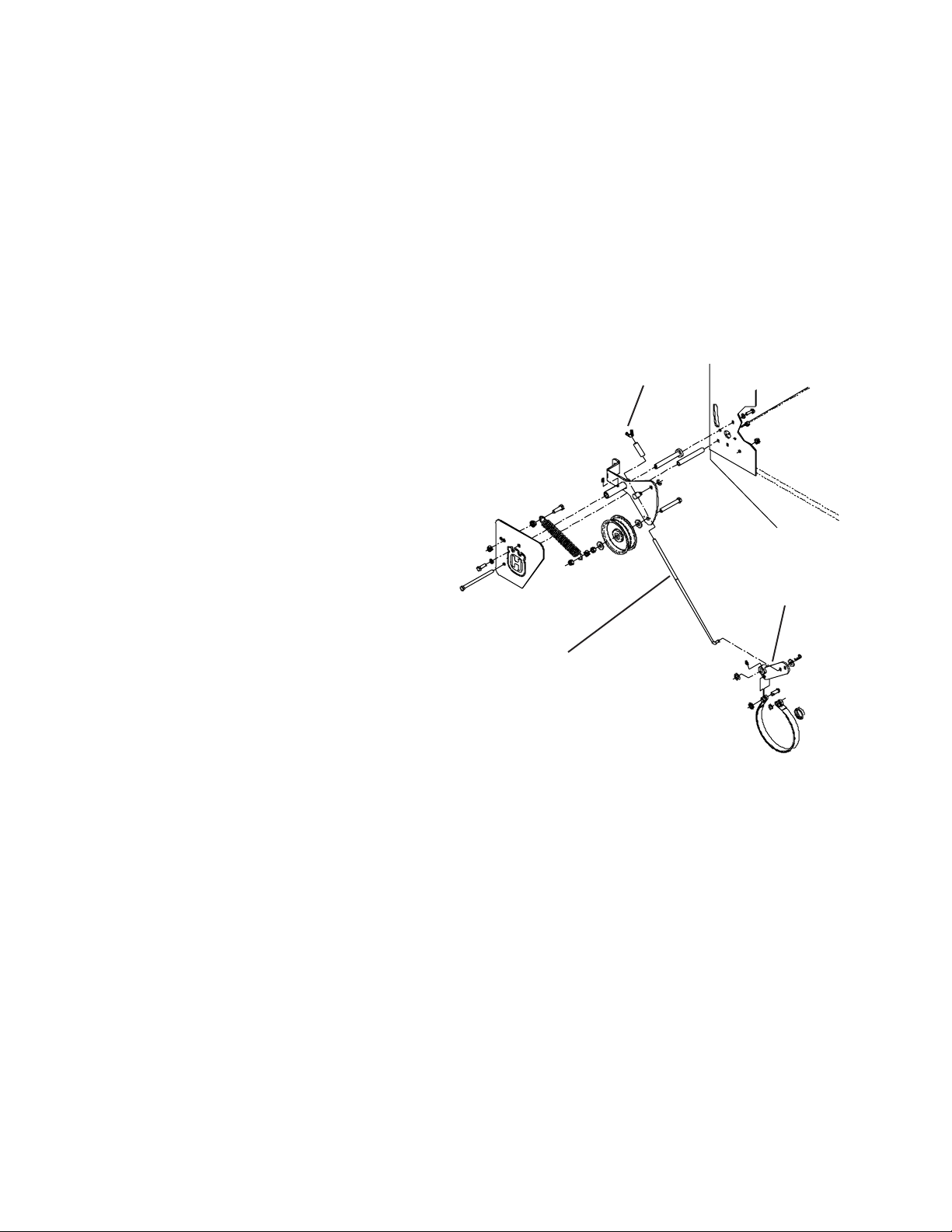
BRAKE ROD ADJUSTMENT
1. Make sure the rod is installed into the proper
hole in the brake arm. The brake rod should be
in bottom hole on the brake arm as shown
below. Never use the upper hole. The proper
adjustment can not be achived in this position.
2. To increase braking. Turn the wing nut down
on the brake rod. Do not turn the wingnut down
to far as this will result a constant braking action
and will excessively wear the brake band and
cause premature failure.
Wingnut
2. Remove lower belt shield from underside of
rear deck for better access to axle adjustment
bolts.
3. Loosen axle pivot bolts and axle adjustment
bolts.
See figure # 1.
4. Place a jack under center of rear deck raise
the jack slightly so axle adjustment bolts may be
removed.
5. With the jack raise or lower the rear deck to
the desired position using the chart to ensure
proper height. Reinstall the axle adjustment
bolts and tighten.
A tapered punch may be used to help align the
holes. See figure #1.
NOTE:
It may be necessary to readjust drive and brake
linkages.
Brake arm
Brake Rod
NOTE:
To achieve the best quality cut, the blades
should be level with the ground or slightly tipped
forward
6
 Loading...