

Page 1

English
Operator Manual
V 554 / 967 672602-00
Please read the operator manual carefully and
make sure you understand the instructions
before using the machine.
Gasoline containing a maximum of 10% ethanol
(E10) is permitted for use in this machine. The
use of gasoline with more than 10% ethanol
(E10) will void the product warranty.
115 98 87-28 Rev. C
Page 2
CONFORMITY CERTIFICATES
USA requirements
Labels are placed on the engine and/or in the engine compartment stating that the machine
will fulll the requirements. This is also applicable to special requirements for any of the states,
(California emission rules etc.). Do not remove these labels. Certicates can also be supplied
with the machine at delivery or written in the Engine manual. Take care of them as they are
valuable documents.
When this product is worn out and no longer
used, return it to the reseller or other party for
recycling.
To implement improvements, specications
and designs can be altered without prior
notication.
Note that no legal demands can be placed
based on the information contained in these
instructions.
Use only original parts for repairs. The use of
other parts voids the warranty.
Do not modify or install non-standard
equipment to the unit without consent from the
manufacturer. Modications to the unit may
cause unsafe operations or damage the unit.
WARNING! Failure to follow cautious
operating practices can result in dangerous
injury to the operator or other persons. The
owner must understand these instructions,
and must let only approved persons who
understand these instructions to operate the
mower.
Each person operating the mower must be of
sound mind and body and must not be under
the inuence of mind altering substances.
WARNING! Engine exhaust, some of its
constituents, and certain vehicle components
contain or emit chemicals known to the State of
California to cause cancer and birth defects or
other reproductive harm.
WARNING! Battery posts, terminals
and related accessories contain lead and lead
compounds, chemicals known to the State of
California to cause cancer and birth defects
or other reproductive harm. Clean your hands
after handling.
WARNING! Engine exhaust and certain
vehicle components contain or emit chemicals
considered to cause cancer, birth defects,
or other reproductive system damage. The
engine exhaust contains carbon monoxide,
which is an odorless, colorless, poisonous gas.
Do not use the machine in enclosed spaces.
©2018 All rights reserved.
Orangeburg SC. Printed in U.S.A.
Page 3

CONTENTS
INTRODUCTION............................................... 4
Congratulations ........................................... 4
Transport on Public Roads ......................... 4
Operating .................................................... 4
Stand On Walk Behind Option .................... 4
SYMBOLS AND DECALS ................................. 6
SAFETY ............................................................ 7
Personal Safety Equipment ........................ 8
Slope Operation .......................................... 8
Safe Handling of Gasoline .......................... 8
Transport..................................................... 9
Spark Arrestor ........................................... 10
CONTROLS .....................................................11
Steering Controls ...................................... 12
Operator Presence Control ....................... 12
Ignition Switch ........................................... 12
Throttle Control ......................................... 12
Choke Control ........................................... 12
Blade Switch ............................................. 12
Fuel Gauge ............................................... 13
Service Meter ............................................ 13
Fuses ........................................................ 13
Stationary Bars ......................................... 13
Deck Lift Lever .......................................... 13
Transport Latch ......................................... 14
Park Brake ................................................ 14
Fuel Tank .................................................. 14
Hydraulic Release Lever ........................... 15
Fuel Shut Off Valve ................................... 15
OPERATION ................................................... 16
Steering .................................................... 16
Operating on Hills ..................................... 17
Moving Machine By Hand ......................... 18
Tracking - Speed....................................... 18
MAINTENANCE .............................................. 19
Safety System ........................................... 21
Battery and Engine Access ....................... 21
V-belts ....................................................... 22
Tire Pressures........................................... 23
Adjusting the Mower Deck ........................ 23
Cutting Blades .......................................... 24
Park Brake ................................................ 24
Neutral Adjustment ................................... 25
Caster Wheels .......................................... 26
LUBRICATION ................................................ 27
Engine Oil ................................................. 28
Wheels and Blades ................................... 28
Transaxle Fluid Change ............................ 29
TROUBLESHOOTING .................................... 30
STORAGE ....................................................... 31
SCHEMATIC ................................................... 32
TECHNICAL DATA .......................................... 33
SERVICE JOURNAL ....................................... 35
Page 4
Congratulations
Thank you for purchasing a Husqvarna standon mower. This machine is built for superior
efciency to rapidly mow primarily large areas. A
control panel that the operator can easily access
and a hydrostatic transmission regulated by
steering controls each contribute to the machine’s
performance.
This manual is a valuable document. Read the
contents carefully before using or servicing the
machine. The following of instructions (use,
service, maintenance) by all who operate this
machine is important for the safety of the operator
and others. It can also largely increase the life
span of the machine and increase its resale
value.
If you sell your machine, be sure to give the
operator manual to the new owner.
The last chapter of this operator manual supplies
a Service Journal. Make sure that service and
repair work are documented. A correctly kept
service journal reduces service costs for the
maintenance and affects the machine’s resale
value. Please contact your dealer for more
information. Take the operator manual along
when the machine is taken to your dealer for
service.
General
In this operator manual, left and right, rearward
and forward are used in relation to the machine’s
usual driving direction.
Continuous dedication to make our products
better requires that specications and design are
subject to change without notice.
Transport on Public Roads
Check applicable road trafc regulations before
transporting on public roads. If the machine is
transported, you must always use approved
fastening equipment and make sure that the
machine is correctly attached. DO NOT operate
this machine on public roadways.
Operating
This machine is constructed only for mowing
grass on lawns and even ground without
obstacles such as stones, tree stumps, etc.
All other types of uses are incorrect. The
manufacturer’s directions concerning operation,
maintenance, and repairs must be carefully
followed.
Lawn mowers and all power equipment, can
be potentially dangerous if used incorrectly.
Safety requires good judgment, careful use in
accordance with these instructions and common
sense.
The machine must only be operated, maintained,
and repaired by persons who know the machine’s
special qualities and who are also knowledgeable
about the safety instructions. Use only approved
repair parts to maintain this machine.
Accident prevention regulations, other general
safety regulations, occupational safety rules, and
trafc regulations must be followed without fail.
Unauthorized modications to the design of the
machine can absolve the manufacturer from
liability for resulting personal injury or damage to
property.
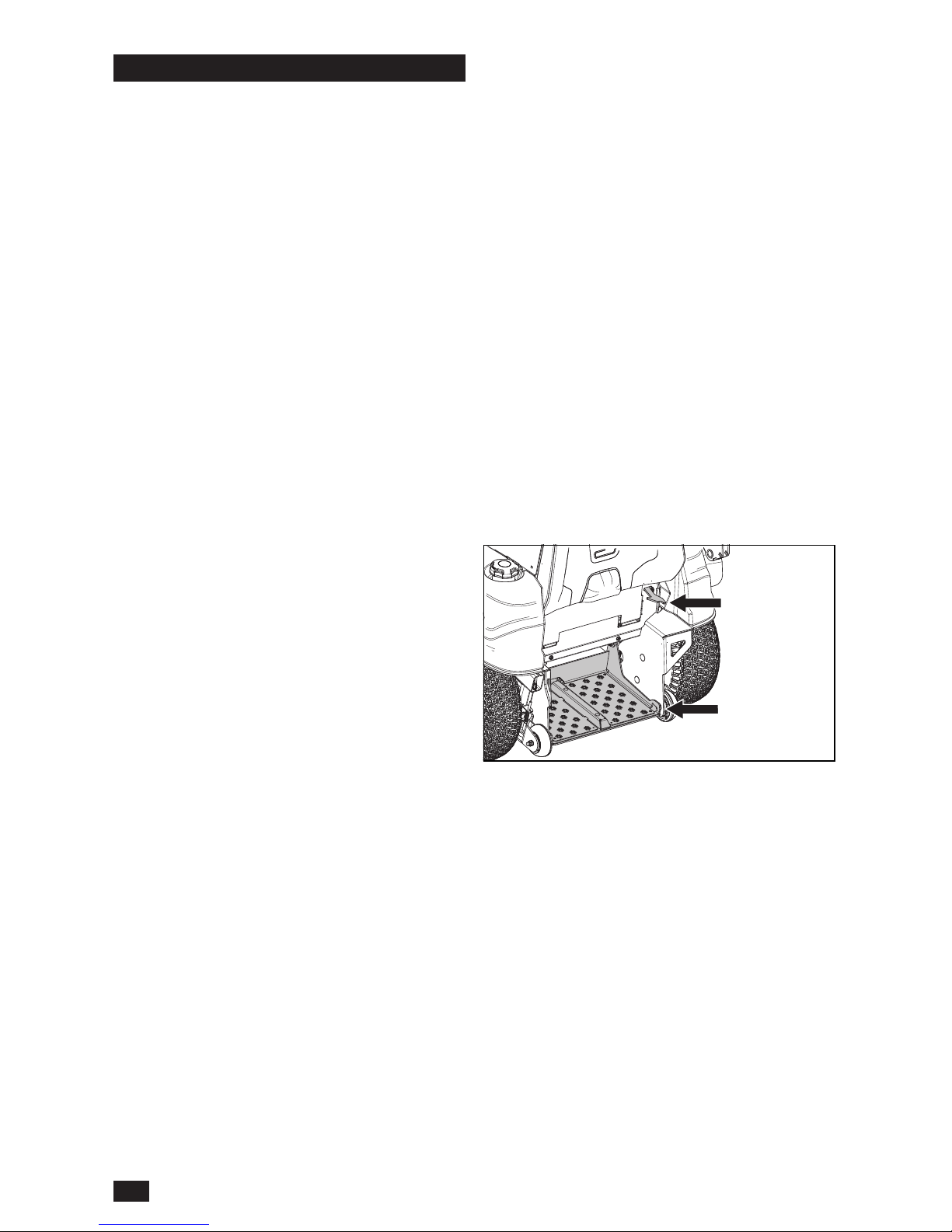
Stand On Walk Behind Option
The mower is designed to be used as either
a stand-on or walk behind unit. The latch on
the rear of the unit releases the platform so
the operator can ride the mower in a standing
position. The latch will hold the platform securely
out of the way if walk behind use is preferred.
4
INTRODUCTION
Page 5

Good Service
Husqvarna's products are sold throughout the
world and only in specialized retail stores with
complete service. This ensures that you as a
customer receive only the best support and
service. Before the product is delivered, the
machine has, for example, been inspected and
adjusted by your retailer. See the certicate in the
Service Journal in this operator manual.
When you need spare parts or support in
service questions, warranty issues, etc., consult
the following professional:
Manufacturing Number
The machine’s manufacturing number can be
found on the printed plate afxed to the frame on
the right side of the operator platform.
Stated on the plate, from the top are:
• The machine’s type designation (I.D.)
• The manufacturer’s type number (Model)
• The machine’s serial number (Serial no.)
Please have the type designation and serial
number available when ordering spare parts.
This manual belongs to the machine with the
manufacturing number:
Engine Transmission
The engine’s manufacturing number is located on
the engine housing, behind the operator cushion.
The plate states:
• The engine’s model.
• The engine’s type.
• Code
Please have these available when ordering spare
parts.
5
INTRODUCTION
Page 6
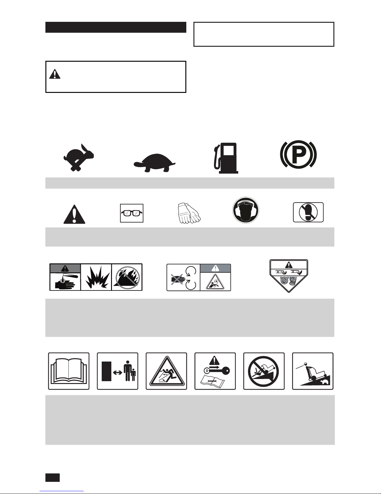
Fast Slow Fuel Park Brake
Danger Use protective
glasses
Use protective
gloves
Wear hearing
protection
Do not
stand here
These symbols are found on the machine and in
the operator manual. Study them carefully until
you know what they mean.
WARNING! Xxxx xxxxxx xxxxx xxxx
xxxxxxxxx xxxxxx xxxxxxxxx.
Used in this publication to tell the reader of a
risk of personal injury or death, particularly if the
reader neglects to obey the instructions in the
manual.
IMPORTANT INFORMATION Xxxx xxxxxx
xxxxx xxxx xxxxxxxxx xxxxxx xxxxxxxxx.
Used in this publication to tell the reader of a
risk of material damage, particularly if the reader
neglects to obey the instructions in the manual.
Used also when there is a possibility for misuse or
misassembly.
Read the
Operator
Manual
Keep a safe
distance from
the machine
Whole body
exposure to
thrown objects
Shut off
the engine,
remove the
key before
maintenance
or repair
Use caution
on slope
to prevent
tipping
Look before
backing up
and reverse
slowly
Warning!
Battery acid is corrosive, explosive
and ammable
Warning!
Do not touch parts
Warning!
Do not use without
deector
or grass catcher
6
SYMBOLS AND DECALS
Page 7

Safety Instructions
These instructions are for your safety. Read them
carefully.
WARNING! THIS CUTTING MACHINE
CAN AMPUTATE HANDS AND FEET AND
THROW OBJECTS. FAILURE TO OBEY
THE FOLLOWING SAFETY INSTRUCTIONS
COULD RESULT IN SERIOUS INJURY OR
DEATH.
WARNING! CHILDREN CAN BE
SERIOUSLY INJURED OR KILLED BY THIS
EQUIPMENT. Carefully read and obey all the
safety instruction that follow.
Protecting Children
Tragic accidents can occur if the operator is
not alert to the presence of children. Children
are frequently attracted to the machine and the
mowing activity. Do not think that children will
stay where you last saw them.
• Keep children out of the mowing area and in the
watchful care of a responsible adult other than
the operator.
• Be alert and turn machine off if a child enters
the area.
• Before and while backing, look behind and
down for small children.
• Do not let children operate the machine.
• Use extreme care when going near blind
corners, shrubs, trees, or other objects that can
block your view of a child.
General Operation
• Read, understand, and obey all instructions on
the machine and in the manual before starting.
• It is recommended that someone knows that
you are mowing and can give aid if there is an
injury or accident.
• Those who operate, maintain, and/or service
this machine must rst read and understand this
Operator Manual. Local laws can regulate the
age of the user. The owner is responsible for
training the users of this equipment.
• The owner and operator of this equipment
can prevent accidents and is responsible for
accidents or injuries occurring to themselves,
other persons and/or property.
• Do not put hands or feet near rotating parts
or under the machine. Keep away from the
discharge opening at all times.
• Only let responsible adults, who are familiar
with the instructions, to operate the machine.
• Clean the area of objects such as rocks, toys,
wire, etc., which could be picked up and thrown
by the blades.
• Be sure the area is has no bystanders before
operating. Stop machine if someone enters the
area.
• Do not mow in reverse unless fully necessary.
Always look down and behind before and while
backing.
• Do not point discharged material toward
someone. Avoid discharging material against a
wall or obstruction. Material can ricochet back
toward the operator. Stop the blades when
going across gravel surfaces.
• Do not operate machine without the full grass
catcher, discharge guard, or other safety
devices in place and working.
• Slow down before turning.
• Always turn off blades, stop engine and remove
keys before dismounting.
• Do not carry passengers. The machine is only
intended for use by one person.
• Operate the machine only in daylight or good
articial light.
• Disengage blades when not mowing. Shut off
engine and wait for all parts to come to a full
stop before cleaning the machine, removing
the grass catcher or unclogging the discharge
guard.
• Do not operate the machine while under the
inuence of alcohol or drugs.
• Look for trafc when operating near or going
across roadways.
• Use more care when loading or removing the
machine into a trailer or truck.
• Always wear eye protection when operating
machine.
• Wear correct Personal Protective Equipment
(PPE) while operating this machine, including
(at a minimum) sturdy footwear, eye protection,
and hearing protection. Do not mow in shorts
and/or footwear with open toes.
• Data shows that operators age 60 years and
above are involved in a large percentage of
mower-related injuries. These operators must
evaluate if they can safely operate the mower
sufciently to protect themselves and others
from serious injury.
• Keep machine free of grass, leaves or other
debris buildup which can touch hot exhaust or
engine parts and burn. Do not let the mower
7
SAFETY
Page 8
deck plow leaves or other debris that can cause
a buildup to occur. Clean oil or fuel spillage
before operating or storing the machine.
• Let machine cool before storage.
WARNING! When using the machine,
approved personal protective equipment must
be used. Personal protective equipment cannot
remove the risk of injury but it will reduce the
degree of injury if an accident does occur.
Speak to your retailer for aid in choosing the
right equipment.
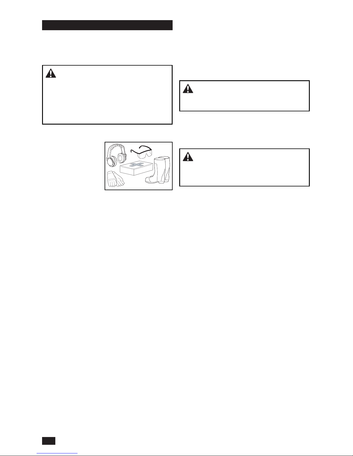
Personal Safety Equipment
• Make sure that rst
aid equipment is
near at hand when
using the machine.
• Do not use the
machine when
barefoot.
• Always wear
protective shoes or boots. Steel toe caps are
recommended.
• Always wear approved protective glasses or a
full visor when assembling or driving.
• Always wear gloves when handling the blades.
• Do not wear loose clothing that can become
caught in moving parts.
• Use ear protectors to avoid damage to hearing.
Slope Operation
Slopes are a major cause related to loss of
control and tip-over accidents, which can result
in severe injury or death. Operation on slopes
requires more care. If you cannot back up the
slope or if you feel uneasy on it, do not mow it.
• Mow across slopes (10 degrees maximum), not
up and down.
• Look for holes, ruts, bumps, rocks, or other
hidden objects. Uneven terrain could overturn
the machine. Tall grass can hide obstacles.
• Select a low ground speed so it will not be
necessary to stop while on the slope.
• Do not mow on wet grass. Tires can lose
traction.
• Avoid starting, stopping, or turning on a slope. If
the tires lose traction, disengage the blades and
continue slowly straight down the slope.
• Move slowly and gradually on slopes. Do not
make sudden changes in speed or direction,
which could cause machine to tip over.
• Use more care while operating machine with
grass catchers or other attachments; the
stability of the machine can be effected.
• Do not use on steep slopes.
• Do not mow near drop-offs, ditches, or
embankments. The machine could suddenly
roll over if a wheel is over the edge or the edge
caves in.
WARNING! Do not drive across hills with
slopes greater than 10 degrees. Do not drive
up or down slopes.
Safe Handling of Gasoline
To avoid personal injury or damage to property,
use care in handling gasoline. Gasoline is very
ammable and the vapors are explosive.
WARNING! The engine and the exhaust
system become very hot during operation.
There is a risk for burns if touched. Let engine
and exhaust system to cool before refueling.
• Do not fuel the machine indoors.
• Extinguish all cigarettes, cigars, pipes, and
other sources of ignition.
• Use only approved gasoline containers.
• Do not remove gas cap or add fuel with
the engine running. Let engine cool before
refueling.
• Do not keep the machine or fuel container
where there is an open ame, spark or pilot light
such as on a water heater or other appliance.
• Before you start refueling, keep the risk of static
electricity to a minimum by touching a metal
surface.
• Do not ll containers in a vehicle or on a truck
or trailer bed with plastic liner. Always put
containers on the ground away from the vehicle
when lling.
• Do not put too much fuel in the tank. Replace
gas cap and tighten securely.
• Remove gas-powered equipment from the truck
or trailer and refuel it on the ground. If this is not
possible, refuel such equipment with a portable
container, rather than from a gasoline dispenser
nozzle.
• Keep the nozzle in contact with the rim of the
fuel tank or container opening at all times until
fueling is complete. Do not use a nozzle lockopen device.
• If fuel is spilled on clothing, change clothing
immediately.
8
SAFETY
Page 9
• Do not start the engine near spilled fuel.
• Do not use gasoline as a cleaning agent.
• If leaks occur in fuel system, the engine must
not be started until problem has been resolved.
• Check the fuel level before each use and leave
space for the fuel to expand, because the heat
from the engine and the sun can otherwise
cause the fuel to expand and overow.
General Maintenance
• Do not use the machine indoors or in spaces
lacking correct ventilation. The exhaust fumes
contain carbon monoxide, an odorless and
poisonous lethal gas.
• Make sure that the equipment is in good
condition and that all nuts and bolts, especially
those fastening the blade attachments, are
correctly tightened and torqued.
CAUTION! Use protective glasses
for maintenance work.
• Maintain or replace safety and instruction labels
as necessary.
• Do not interfere with the intended operation
of or reduce the protection given by a safety
device. Check their operation regularly. DO
NOT operate a machine with a safety device
that does not operate correctly.
• Check grass catcher components and the
discharge guard frequently and replace with
manufacturer’s recommended parts when
necessary.
WARNING! The engine must not be
started when protective plates for the mower
deck’s drive belt are removed.
• Do not change the settings of engine controllers
and avoid running the engine at overly high
engine speeds. If you run the engine too fast,
machine components could be damaged.
• To reduce the risk of re, keep machine free of
grass, leaves or other debris buildup. Clean oil
or fuel spills and remove fuel-soaked debris. Let
machine cool before storing.
• Stop to do an inspection of the equipment if you
run over or into anything. If necessary, make
repairs before starting.
• Do not make adjustments or repairs with the
engine running.
• The blades are sharp and can cause cuts and
gashes. Wrap blades or use protective gloves
when handling them.
• Check the park brake’s operation regularly.
Adjust and service as necessary.
• Do not work with the starter circuit if there is
spilled fuel.
• Make sure that the fuel ller cap is mounted
tightly and no ammable substances are kept in
an open vessel.
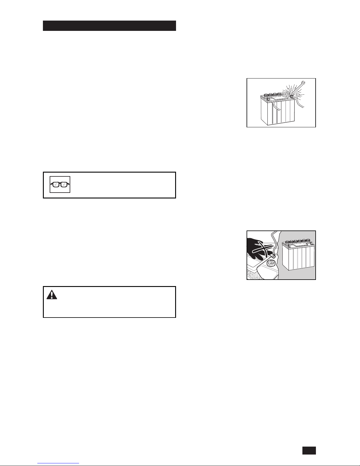
• Sparking can occur
when working with
the battery and the
heavy cables of the
starter circuit. This
can cause battery
explosion, re or eye
injury. Sparking will
not occur after the grounding cable (normally
negative, black) is removed from the battery.
• Disconnect the grounding cable from the battery
rst and reconnect it last.
• Do not make a bridge short circuit across the
starter relay to run the starter.
• Be very careful when handling battery acid.
Acid on skin can cause serious corrosive burns.
If you spill battery acid on your skin, rinse
immediately with water.
• Acid in the eyes can cause blindness, contact a
doctor immediately.
• Be careful when
servicing the battery.
Explosive gases form
in the battery. Do
not do maintenance
on the battery when
smoking or near
open ames or
sparks. The battery can explode and cause
serious injury or damage.
• The machine is tested and approved only
with the equipment originally supplied or
recommended by the manufacturer. Only use
approved repair parts for the machine.
• The mulch blades must only be used in familiar
areas when higher quality mowing is necessary.
• Regularly clean the deck and the underside of
the deck. Avoid spraying engine and electrical
components with water.
Transport
• The machine is heavy and can cause serious
crushing injuries. Be more careful when it is
loaded on or removed from a vehicle or trailer.
• Use full width ramps for loading machine into a
trailer or truck.
• Check and abide by local trafc regulations
before transporting the machine on roads.
9
SAFETY
Page 10
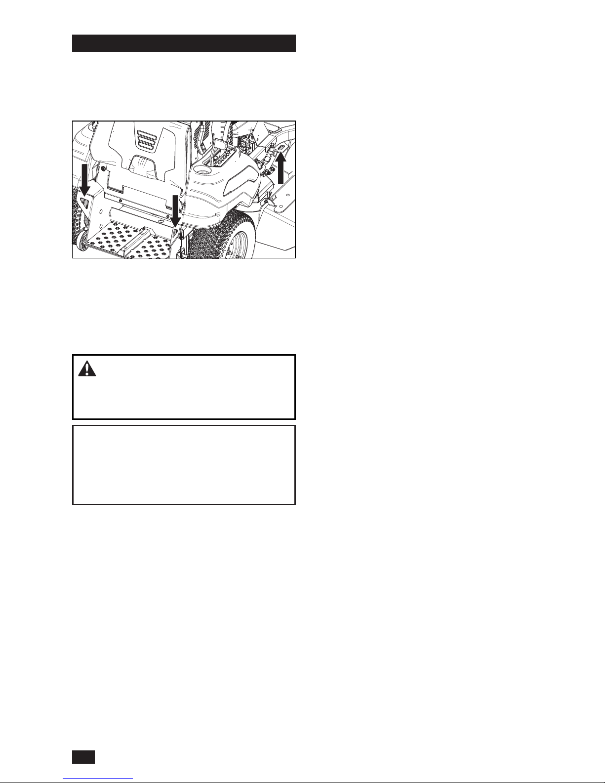
• Use an approved trailer to transport the
machine. Turn off the fuel supply. Fasten the
machine down with approved devices such as
bands, chains or straps at the tie down points
on the mower.
• Load the unit onto truck or trailer by reversing
up ramps of sufcient strength using a slow
speed. Do not lift! The machine is not intended
to be lifted by hand.
• When loading or removing this machine, do not
use more than the maximum recommended
operation angle of 10 degrees.
WARNING! Use extreme care when
loading the machine into a truck or trailer using
ramps. There is the possibility of serious injury
or death if the machine falls off the ramps.
IMPORTANT INFORMATION The park brake
is not sufcient to lock the machine in place
during transport. Make sure the machine is
correctly fastened to the transport vehicle.
Always reverse the machine onto the transport
vehicle to avoid tipping it over.
Spark Arrestor
This mower is equipped with an internal
combustion engine and must not be used on
or near unimproved forested, bush covered
or grassy lands unless the engine’s system is
equipped with a spark arrestor meeting applicable
local or state laws. Federal laws apply on federal
lands. If a spark arrestor is used, it must be
maintained in good working order by the operator.
A spark arrestor for the mufer is available
through your authorized Husqvarna dealer.
10
SAFETY
Page 11
1
2
3
4
5
6
7
8
9
10
11
12
13
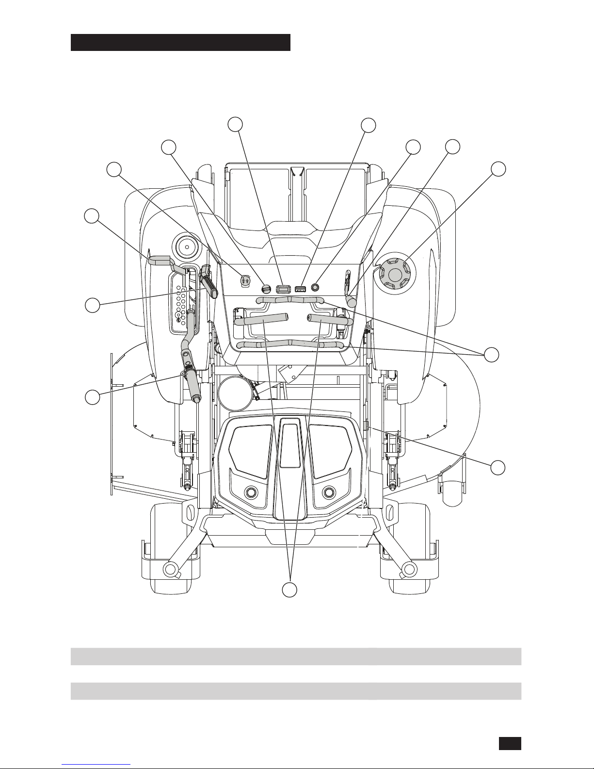
This operator manual describes the Husqvarna
commercial stand-on mower. The mower is tted
with a four-stroke overhead valve engine.
Transmission from the engine is made via
belt-driven hydraulic pumps. Using the left and
right steering controls, the ow is regulated and
thereby the direction and speed.
1. Steering controls
2. Hydraulic release lever
3. Throttle control
4. Fuel tank cap
5. Choke control
6. Fuel gauge
7. Service meter
8. Ignition switch
9. Blade switch
10. Transport latch
11. Park brake
12. Deck lift lever
13. Stationary bars
11
CONTROLS
Page 12
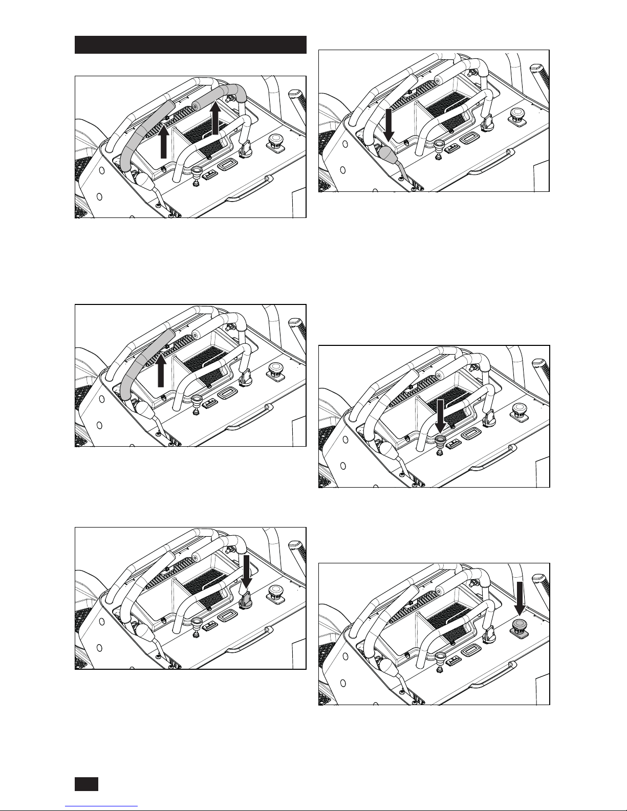
Steering Controls
The machine’s direction is variable using the two
steering controls. The steering controls can be
moved forward and back from a neutral position.
See Steering in the Operation section.
Throttle Control
The throttle control regulates the engine speed
and the rate of rotation of the blades, assuming
the blade switch is pulled out.
To increase or decrease the engine speed, the
control is moved forward or back respectively.
Avoid idling the engine for long periods, as there
is a risk of fouling the spark plugs. USE FULL
THROTTLE WHEN MOWING, for best mower
performance and battery charging.
Choke Control
The choke control is used for cold starts to
provide the engine with a richer fuel mixture. For
cold starts, pull the control up.
Ignition Switch
The ignition switch is used to start and stop the
engine.
Blade Switch
To engage the mower deck, pull the knob out;
mower blades are disengaged when the knob is
pressed down.
Operator Presence Control
The left steering control is also the Operator
Presence Control (OPC). The lever must be down
and parallel with the right lever for operation.
12
CONTROLS
Page 13
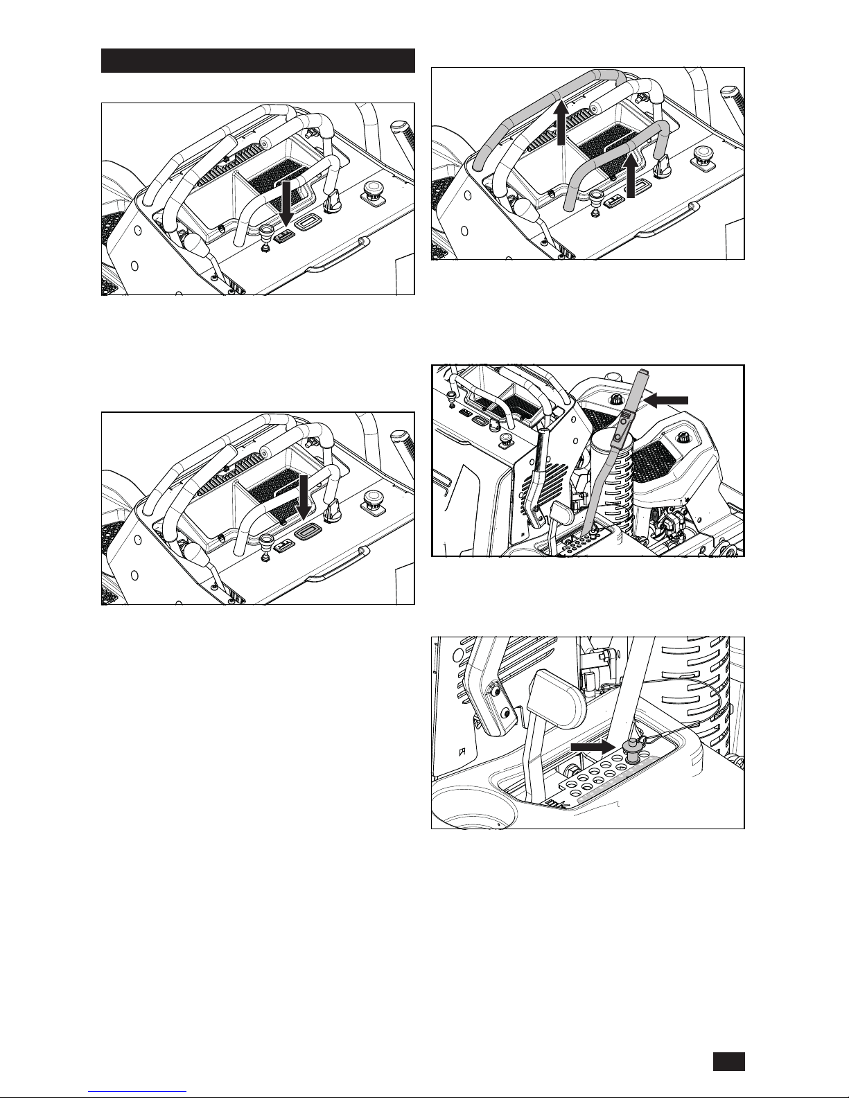
Service Meter
The service meter is located on the left hand
control panel and shows the total operating time
with the blades engaged.
After every 50 hours of operation, an oil can icon
will appear and stay on for two hours, before
an automatic reset occurs. To manually reset
the meter, turn the key off and on ve times at
one second intervals. To service the engine and
mower, see the Service Journal of this manual.
Fuel Gauge
The fuel gauge for the fuel tank is located on the
control panel. Sensors will indicate fuel levels.
The meter will ash yellow when the tank level is
approximately 3.8 litres (1.0 gallons).
Deck Lift Lever
To set the deck cutting height, press the button
on the top of the height pin to remove it. Slip the
height pin into the hole for the desired cutting
height.
The cutting height can be set from 38 mm to 127
mm (1-1/2" to 5").
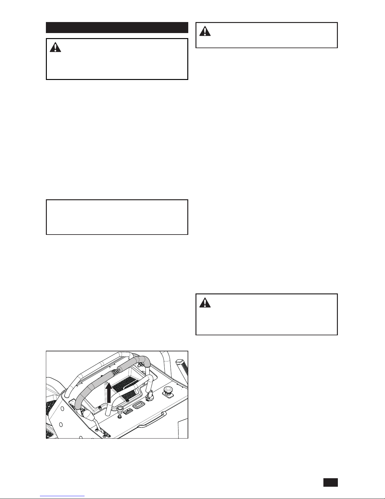
Stationary Bars
Located on the control panel, the stationary bars
are xed supports that assist the operator when
using the steering controls.
Fuses
The fuse box is located behind the operator
cushion. The fuses are the same type used in
automobiles. Check the decal for amps and
purposes.
13
CONTROLS
Page 14
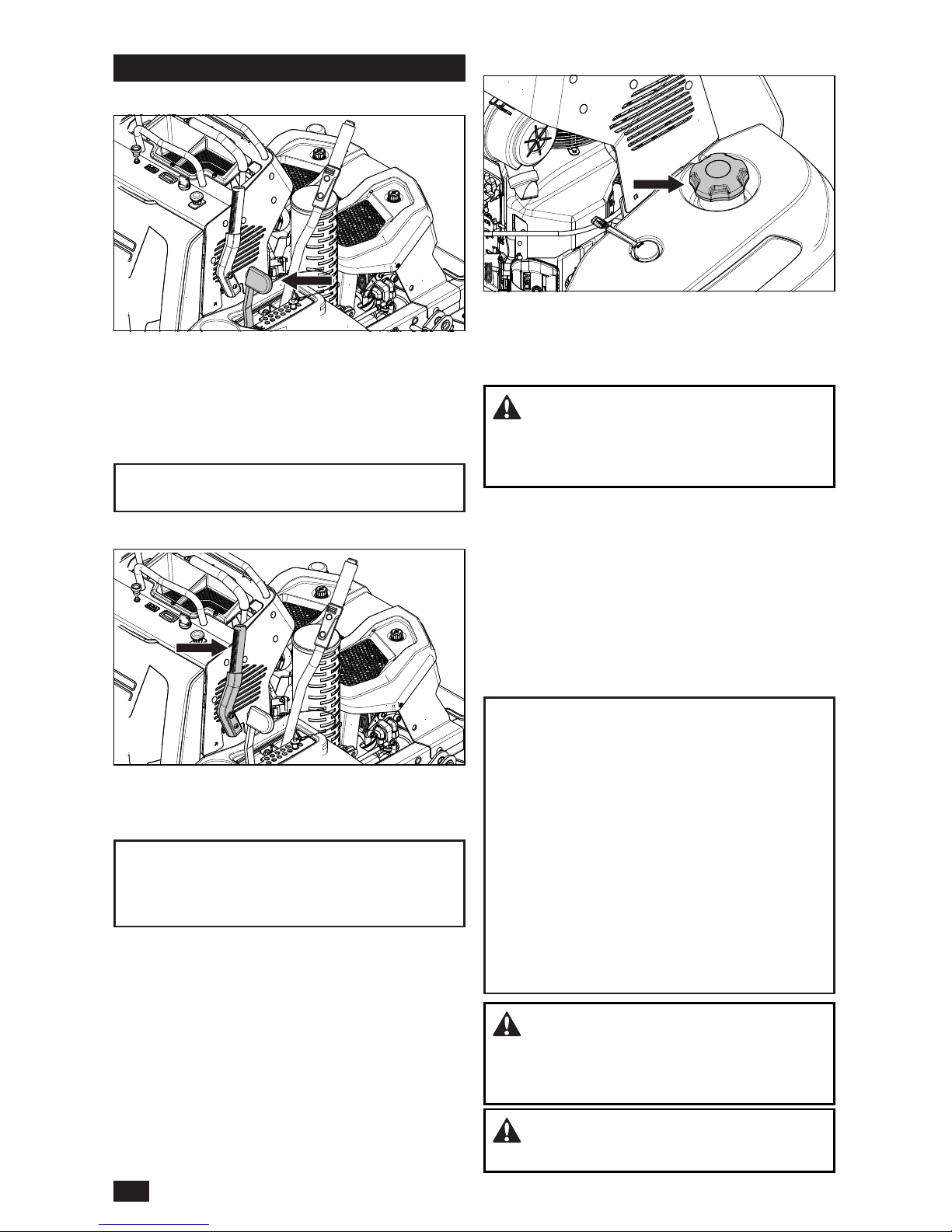
Transport Latch
The transport latch will set the deck to the
transport height of 5" when the lift lever is pulled
back. The latch can also used to mow at the 5"
cutting height.
To release the deck left lever out of transport
mode, push the transport latch forward.
IMPORTANT INFORMATION Always raise the
deck to the highest position for transport.
Fuel Tank
Read the safety instructions before refueling. The
capacity for the tank is 24.6 litres (6.5 gallons).
Regularly check the gas cap gasket for damage
and keep the cap properly tightened.
WARNING! Fill to bottom of ller neck.
Do not overll. Wipe off spilled oil or fuel. Do
not store, spill or use gasoline near an open
ame.
The engine will run on a minimum of 87-octane
unleaded gasoline (no oil mix). Environmentally
adapted alkylate gasoline can be used. See the
Technical Data section in this manual concerning
ethanol fuel. Methanol fuel is not allowed. Do
not use E85 alcohol based fuel. Damage to the
engine and components may occur.
When operating in temperatures below 0°C
(32°F), use fresh, clean winter grade gasoline to
help insure good cold weather starting.
IMPORTANT INFORMATION Experience
indicates that alcohol blended fuels (called
gasohol, ethanol or methanol) can attract
moisture which leads to separation and
formation of acids during storage. Acidic gas
can damage the fuel system of an engine while
in storage. To avoid engine problems, the fuel
system must be emptied before storage of 30
days or longer. Drain the gas tank, start the
engine and let it run until the fuel lines and
carburetor are empty. Use fresh fuel the next
season. See Storage for more information. Do
not use engine or carburetor cleaners in the
fuel tank or permanent damage may occur.
WARNING! The engine and the exhaust
system, become very hot during operation.
There is a risk for burns if touched. Let engine
and exhaust system to cool before refueling.
WARNING! Gasoline is highly ammable.
Observe caution and ll the tank outdoors.
Park Brake
The park brake is found on the right side of the
control console. Pull the lever back to engage the
brake and push forward to release it.
IMPORTANT INFORMATION The machine
must stand still when engaging the park brake.
Release the park brake before moving the
mower.
14
CONTROLS
Page 15
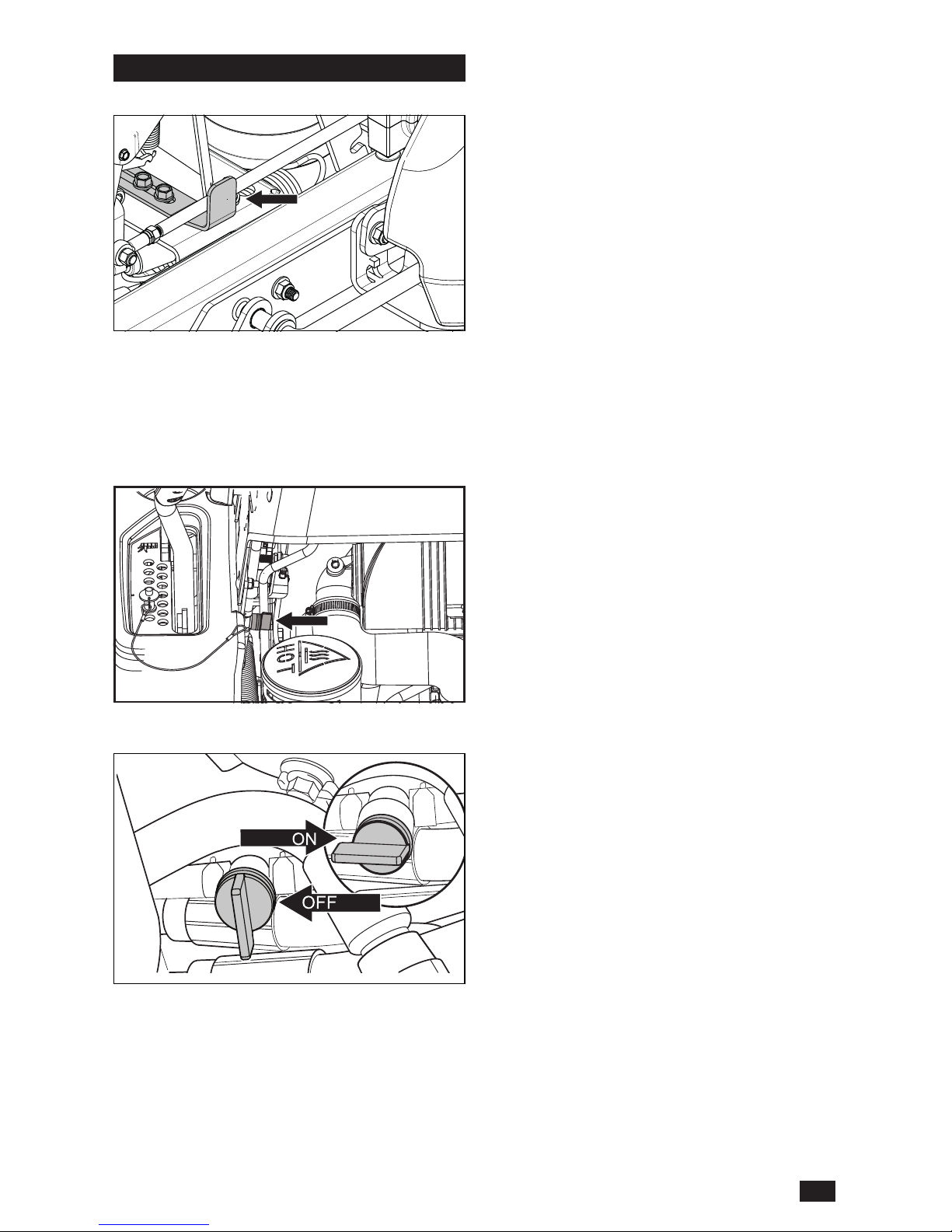
Hydraulic Release Lever
The hydraulic release allows the mower to be
moved by hand when not running. See Moving
Machine By Hand in the Maintenance section.
Fuel Shut Off Valve
The fuel shut off valve is located on the right side
next to the engine.
The valve is off when the handle tab is turned
perpendicular to the fuel line.
15
CONTROLS
Page 16
Read the Safety section and following pages, if
you are unfamiliar with the machine.
Training
Due to unique steering capabilities, zero turn
mowers are far more maneuverable than typical
mowers.
Review this section fully before trying to move the
mower under its own power. When rst operating
the mower or until becoming comfortable with
controls, use a reduced throttle speed and
reduced ground speed. DO NOT move control
levers to the furthest forward or reverse positions
during initial operation.
First time users must become familiar with the
mower’s movement on a hard surface, such as
concrete or asphalt BEFORE trying to operate on
turf.
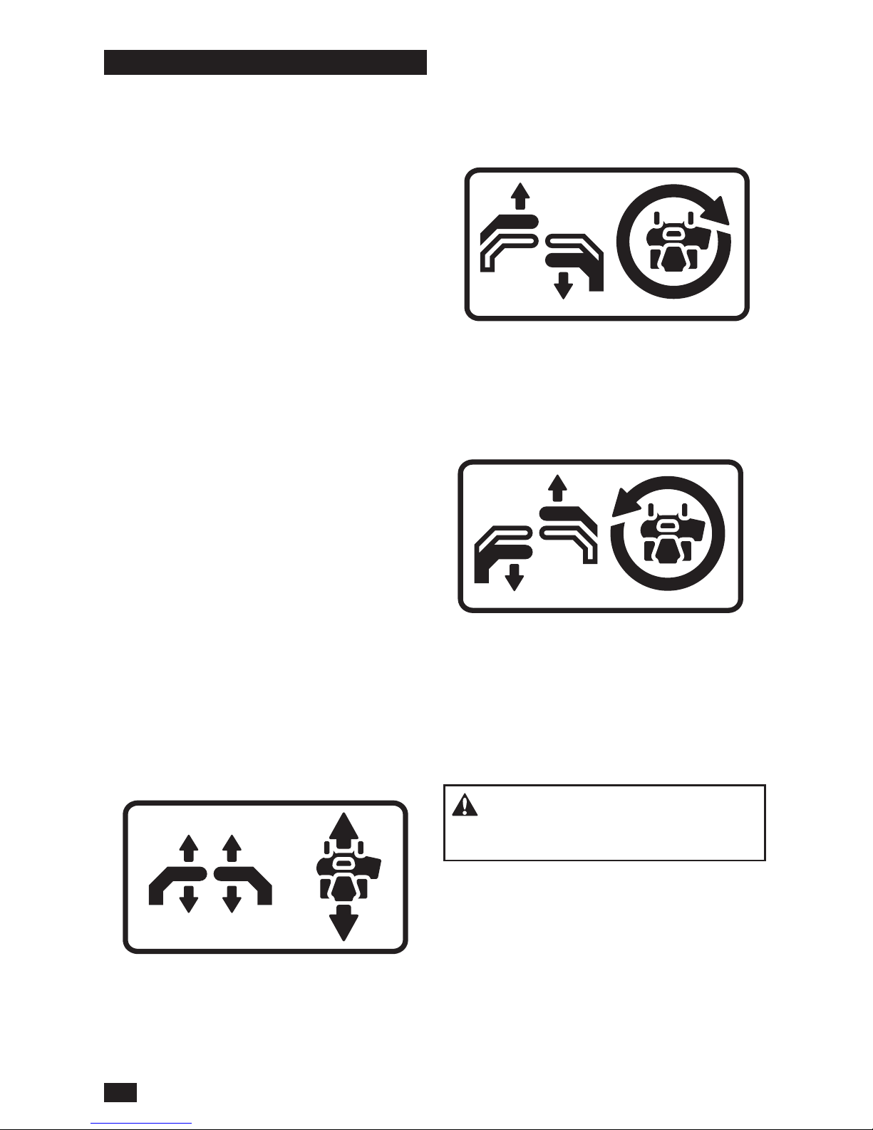
Steering
The direction and speed of the mower’s
movements are effected by the movement of
the control lever(s) on each side of mower. The
left lever controls the left wheel. The right lever
controls the right wheel.
First time users must push the mower (see
Moving Machine By Hand in the Operation
section) to an open, at area without other
persons, vehicles or obstacles nearby.
To move forward and back
To move the unit under its own power, start the
engine (see Before Starting in the Operation
section). Adjust the engine speed to idle but do
not engage the blades.
Slowly move the two control levers forward
slightly. This will let the mower start moving
forward in a straight line. Release the control
levers back to the neutral position and stop the
mower from moving.
Pull back slightly on control levers, allowing the
mower to move backwards. Release the control
levers to the neutral position to stop the mower
from moving.
To turn to the right
While moving in a forward direction, pull the right
lever back towards the neutral position while
maintaining the position of the left lever, this will
slow the rotation of the right wheel and cause the
machine to turn in that direction.
To turn to the left
While moving in a forward direction pull the left
lever back towards the neutral position while
maintaining the position of the right lever, this will
slow the rotation of the left wheel and cause the
machine to turn in that direction.
To zero turn
While moving in a forward direction, rst pull the
two control levers back until the mower stops or
slows signicantly. By moving one lever slightly
forward and the other in the reverse, complete
the turn.
Before Starting
WARNING! Make sure the work area is
free from of stones and other objects that could
be thrown by the rotating blades.
1. Read the sections on Safety and Controls
before starting the machine.
2. Perform the daily maintenance before
starting (see Maintenance Schedule in the
Maintenance section).
3. Check that there is sufcient fuel in the fuel
tank.
4. Adjust the mower deck to the desired
cutting height. See Cutting Height in the
Maintenance section.
16
OPERATION
Page 17
Mowing Tips
• Find and ag rocks and other xed objects to
avoid collisions.
• Start with a high cutting height and reduce it
until the desired mowing result is attained. Cut
the average lawn to 6.4 cm (2-1/2") during the
cool season and over 7.6 cm (3") during the hot
months. For healthier and better looking lawns,
mow often after moderate growth.
• For best cutting performance, mow grass over
15.2 cm (6") in height twice. Make the rst cut
relatively high; the second to the desired height.
• The mowing result will be best with a high
engine speed (the blades rotate rapidly) and
low speed (the operator moves slowly). If the
grass is not too long and dense, the operating
WARNING! The engine exhaust contains
carbon monoxide, which is a odorless,
colorless, poisonous gas. Do not use the
machine in enclosed spaces.
The following conditions must be fullled before
the engine can be started:
• The blade switch must be pressed down into
the disengaged position.
• The park brake must be engaged.
• Both steering controls must be in the neutral
position.
Starting the Engine
1. Move the throttle lever to the mid throttle
position. If the engine is cold, pull the choke
control up.
2. Press in and turn the ignition key to the start
position.
IMPORTANT INFORMATION Do not run the
starter for more than ve seconds each time. If
the engine does not start, wait approximately
ten seconds before trying again.
3. When the engine starts, immediately release
the ignition key back to the run position.
Slowly push in the choke control knob, if it
was used to start a cold engine.
4. Set the engine speed with the throttle. Allow
the engine to run at a moderate speed,
approximately mid throttle, for a short time
before use. USE FULL THROTTLE WHEN
MOWING (no choke).
Running
1. Move throttle control to full throttle (rabbit
symbol).
2. Engage the OPC.
3. Release the park brake.
4. Engage the mower deck by pulling the blade
switch up.
WARNING! Make sure that no one is
near mower when engaging blade switch.
5. Grasp the speed control bar and the steering
controls to start movement.
NOTE: When mowing in reverse, use the smaller
bar at the rear of the console.
Stopping the Engine
1. Move the steering controls back to the neutral
position and release the OPC lever.
2. Disengage the mower deck by pressing the
blade switch down.
3. Move the throttle to the minimum position
(tortoise symbol).
4. Engage the park brake.
5. Turn the ignition key to the stop position and
remove key. Remove the key when leaving
the mower to prevent unapproved use.
Operating on Hills
Read the Safety Instructions Driving on Slopes
in the Safety section.
• Use the slowest speed possible before starting
up or down hills.
• If stopping is fully necessary, pull steering
controls into the neutral position.
• Pull the steering controls back to the center of
the mower and push forward to regain forward
movement.
• Try not to stop or change speed on hills.
• Make all turns slowly.
WARNING! Do not use the mower on
terrain that slopes more than 10 degrees. Mow
slopes side to side, never up and down. Avoid
sudden directional changes.
17
OPERATION
Page 18
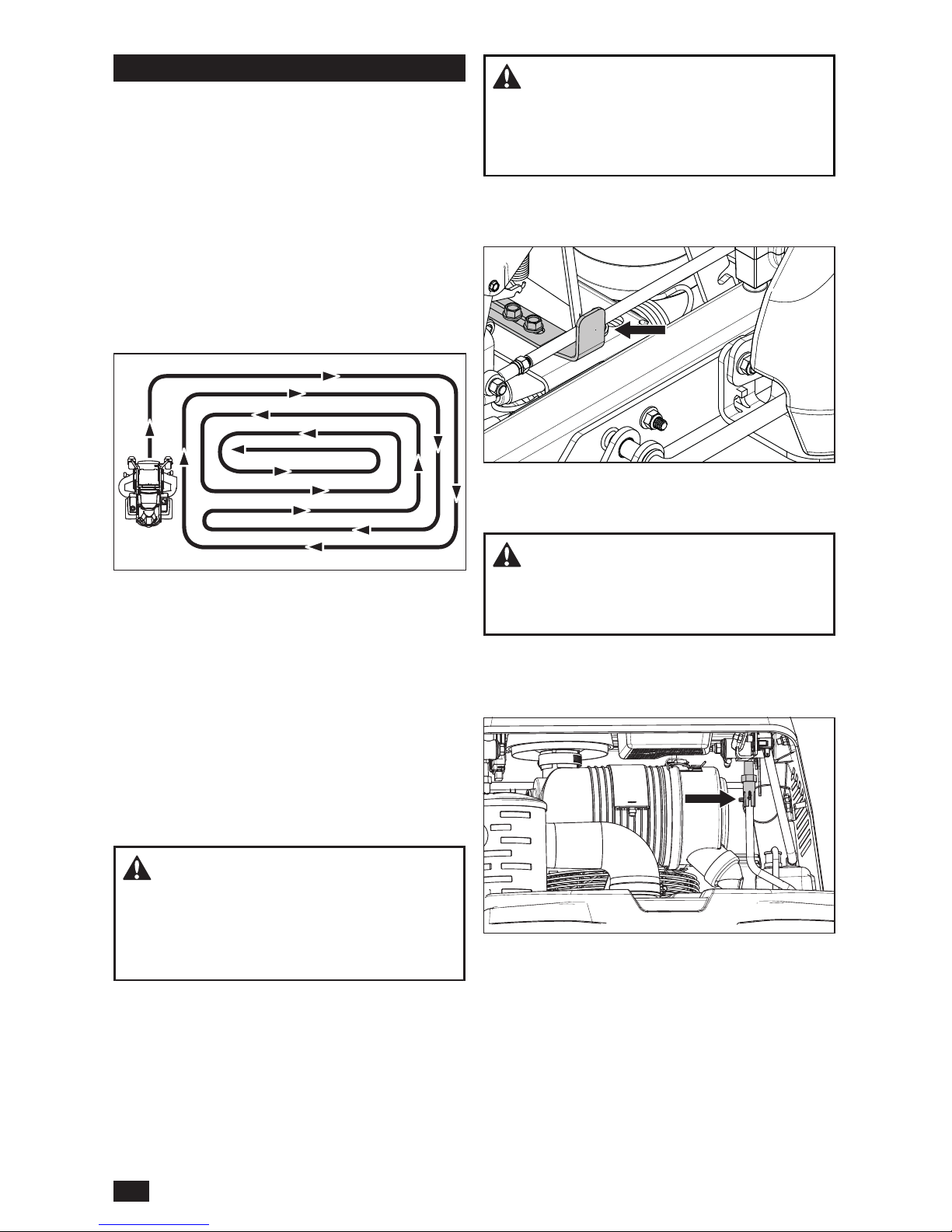
Moving Machine By Hand
When pushing or pulling the mower with the
engine not running, engage the hydraulic release
lever.
speed can be increased without negatively
affecting the mowing result.
• The nest lawns are obtained by mowing
often. The lawn becomes more even and the
grass clippings more evenly distributed over
the mown area. The total time taken is not
increased as a higher operating speed can be
used without poor mowing results.
• When mowing large areas, start by turning to
the right so that clippings will discharge away
from shrubs, fences, driveways, etc. After one
or two rounds, mow in the opposite direction
making left hand turns until nished.
• Avoid mowing wet lawns. The mowing result
is poorer because the wheels sink into the soft
lawn, clumps build, and grass clippings fasten
under the cowling.
• Hose the mower deck underside with water
after each use. When cleaning, the mower deck
shall be raised into the transport position. Make
sure the mower is cooled and the engine is off.
• Use compressed air to clean top surface of
the deck. Avoid ooding water on top surface,
engine and electrical components.
• When the mulching kit is used, it is important
that the mowing interval is more frequent.
WARNING! Do not make adjustments
unless:
• the engine is stopped,
• the park brake is engaged
• the ignition key is removed,
CAUTION! With the hydraulic release
engaged, the mower will have unrestricted
motion if the parking brake is not engaged. Do
not use the release lever if the mower is not on
a level surface.
Access the lever on the left side of the unit. Set
the deck to the lowest position when engaging the
bypass linkage. To engage, slide the lever out.
Load the machine into truck or trailer by driving up
ramps in low gear. DO NOT LIFT! The machine is
not intended to be lifted by hand.
WARNING! Use extreme caution when
loading the machine into a truck or trailer using
ramps. There is the possibility of serious injury
or death if the machine falls off the ramps.
Tracking - Speed
1. Pull the retaining clip out of the vertical control
rod.
2. Adjust the nylon coupler until the desired
speed is achieved. When the unit tracks
straight and is at appropriate maximum
forward speed, reinsert the retaining clip to
lock the coupler in place.
18
OPERATION
Page 19
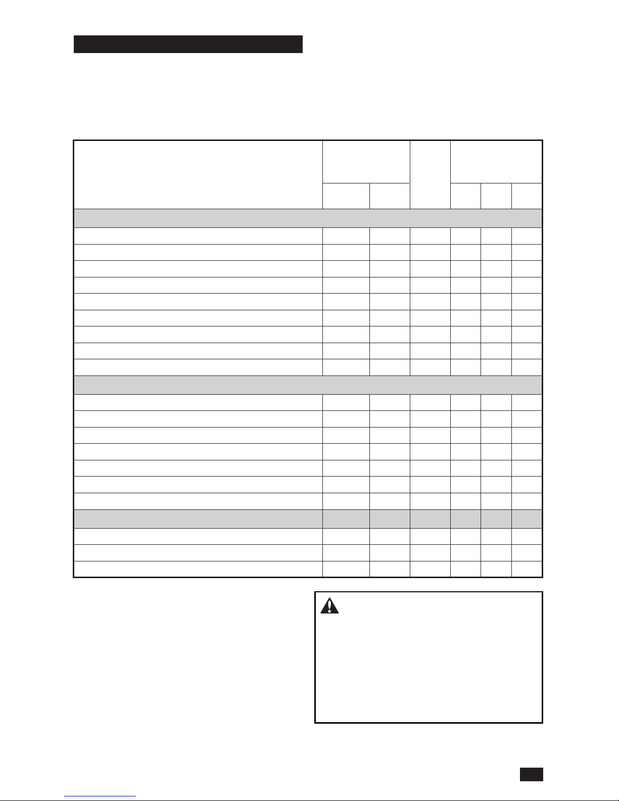
Maintenance Schedule
Following is a list of maintenance procedures
that must be performed on the machine. For
those points not described in this manual, visit an
authorized service workshop. An annual service
MAINTENANCE
DAILY
AT
LEAST
ONCE
EACH
YEAR
MAINTENANCE
INTERVAL
IN HOURS
BEFORE AFTER 50 250 500
CHECK
Park brake for adjustment
● ● ● ● ●
Engine’s oil level (every refueling)
■
Safety system
●
For fuel and oil leakages
♦
For damage
♦ ♦ ♦ ♦
For loose hardware (screws, nuts)
●
For mower deck damage
●
Tire pressures
● ● ● ●
Battery connections
● ● ● ●
CLEAN
Engine’s cooling air intake
■
Under the mower deck
● ● ● ●
Around the engine
♦ ♦ ♦ ♦
Around belts, belt pulleys
♦ ♦ ♦ ♦
Engine’s cooling air intake
1)
■ ■ ■ ■
Air cleaner foam pre-lter
1)
■ ■
Air cleaner paper lter cartridge
1)
■ ■
ALSO
Inspect mufer/spark arrestor
♦ ♦ ♦ ♦
Start the engine & blades, listen for unusual sounds
♦
Sharpen
2)
/ Replace mower blades
● ● ● ●
1)
In dusty conditions, cleaning and replacement
are required more often.
2)
Performed by authorized service workshop.
carried out by an authorized service workshop
is recommended to maintain your machine in
the best possible condition and to ensure safe
operation.
Read General Maintenance in the Safety
section.
● = Described in this manual
♦ = Not described in this manual
■ = Refer to the engine manufacturer’s manual
WARNING! Before performing service or
adjustment:
• Engage the park brake.
• Place the blade switch in the disengaged
position.
• Turn the ignition switch to OFF position and
remove the key.
• Make sure the blades and all moving parts
have stopped.
19
MAINTENANCE
Page 20
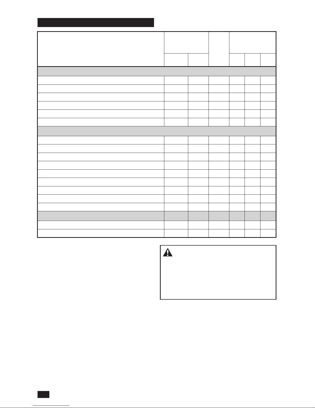
MAINTENANCE
DAILY
AT
LEAST
ONCE
EACH
YEAR
MAINTENANCE
INTERVAL
IN HOURS
BEFORE AFTER 50 250 500
CHECK
Throttle and choke cables for adjustment
■
Mower deck for adjustment
● ●
Condition of belts, belt pulleys
● ●
Caster wheels (every 200 hours)
● ●
Hydraulic oil level
●
Engine valve clearance
4)
♦ ♦
CHANGE
Spark plugs
■ ■
Engine oil
1)
■ ■
Engine oil lter
■ ■
Fuel lter
■ ■
Paper air lter
2)
■ ■
Air cleaner foam pre-lter
2)
■
Air cleaner paper lter cartridge
2)
■ ■
Hydraulic oil
3)
● ● ●
Hydraulic oil lter
3)
● ● ●
ALSO
Dismantle and inspect starter
4)
♦
Perform the 500-hour service
4)
♦ ♦
1)
First change after 8–10 hours. When
operating with a heavy load or at high ambient
temperatures, replace every 50 hours.
2)
In dusty conditions, cleaning and replacement
are required more often.
3)
Maintenance interval determined by type of
oil used. See Qualied Hydraulic Oils in the
Lubrication section.
4)
Performed by authorized service workshop.
● = Described in this manual
♦ = Not described in this manual
■ = Refer to the engine manufacturer’s manual
Hardware
Check daily. Inspect the entire machine for loose
or missing hardware.
WARNING! Do not short battery
terminals by allowing a wrench or other objects
to contact the two terminals at the same time.
Before connecting battery, remove metal
bracelets, wristwatch bands, rings, etc.
Positive terminal must be connected rst to
prevent sparks from accidental grounding.
20
MAINTENANCE
Page 21
Safety System
The machine is equipped with a safety system
that prevents starting or driving under the
following conditions.
The engine can only be started when:
• the mower deck is disengaged.
• the park brake is engaged.
Make daily inspections to make sure that the
safety system works by trying to start the engine
when one of the conditions is not met. Change
the conditions and try again.
Make sure the engine stops when the park brake
is not engaged and the operator leaves the
seated position.
Make sure the engine stops if the mower blades
are engaged and the driver leaves the seated
position.
Battery and Engine Access
The operator cushion can be lowered or removed
for access to the battery and engine.
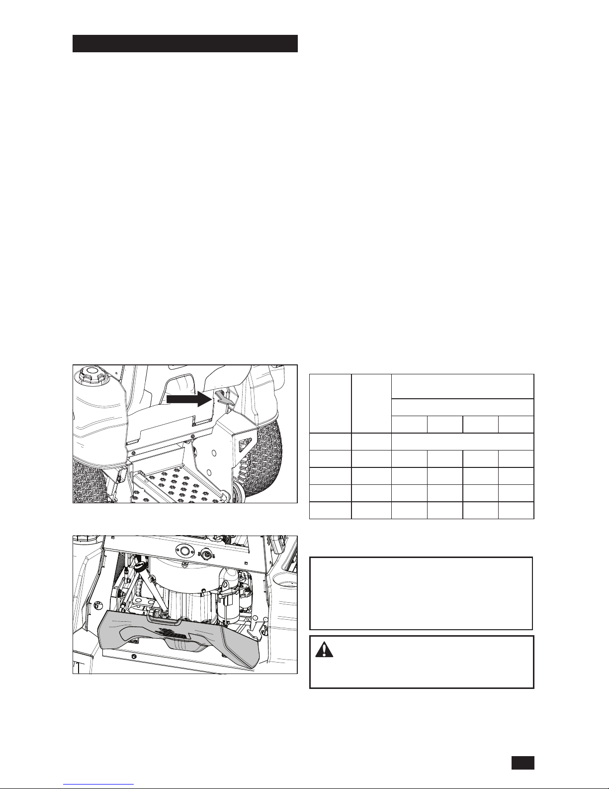
To lower the cushion, release the latch at the
lower right side and tip the cushion down.
To remove, tip the lowered the cushion up slightly
and lift the back edge up.
If the battery is too weak to start the engine, it
must be recharged.
Jumper Cable Use
1. Connect each end of the RED cable to the
POSITIVE (+) terminal on each battery, taking
care not to short against chassis.
2. Connect one end of the BLACK cable to the
NEGATIVE (–) terminal of the fully charged
battery.
3. Connect the other end of the BLACK cable
to a good CHASSIS GROUND on the mower
with the discharged battery, away from the
fuel tank and battery.
To remove cables, reverse order
1. Remove BLACK cable rst from chassis and
then from the fully charged battery.
2. Remove RED cable last from the two
batteries.
The mower is equipped with a maintenance
free battery and does not need servicing.
However, periodic charging of the battery with an
automotive type battery charger will extend its life.
• Keep battery and terminals clean.
• Keep battery bolts tight.
• See chart for charging times.
STD
BATTERY
STAT E
OF
CHARGE
APPROXIMATE CHARGING TIME*
TO FULL CHARGE AT 80
O
F
Maximum Rate at:
50 Amps 30 Amps 20 Amps 10 Amps
12.6V 100%
- FULL CHARGE -
12.4V 75% 20 min. 35 min. 48 min. 90 min.
12.2V 50% 45 min. 75 min. 95 min. 180 min.
12.0V 25% 65 min. 115 min. 145 min. 280 min.
11.8V 0% 85 min. 150 min. 195 min. 370 min.
*Charging time depends on battery capacity,
condition, age, temperature and efciency of charger
IMPORTANT INFORMATION Do open or
remove caps or covers. Adding or checking the
level of electrolyte is not necessary.
Always use two wrenches for the terminal
screws.
CAUTION! Lead-acid batteries generate
explosive gases. Keep sparks, ame and
smoking materials away from batteries.
21
MAINTENANCE
Page 22
Battery Removal
Corrosion and dirt on the battery and terminals
can cause the battery to lose power.
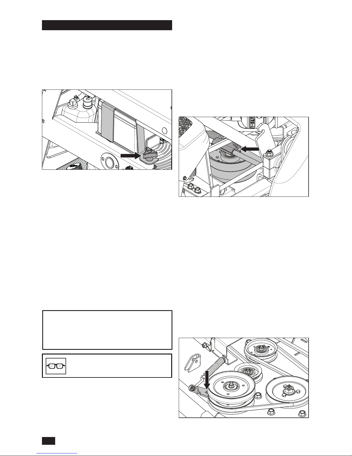
1. Lower the operator cushion to access the
battery.
2. Remove the knob from the battery bracket
and remove the bracket from the battery.
3. Using two wrenches, disconnect the BLACK
battery cable then the RED battery cable.
4. Carefully remove the battery from the mower.
Cleaning
5. Rinse the battery with plain water and dry.
6. Clean the terminals and battery cable ends
with a wire brush.
Replacing
7. Install the new battery with terminals in the
same position as the old battery.
8. Connect RED battery cable rst to positive (+)
battery terminal.
9. Connect BLACK grounding cable to negative
(–) battery terminal.
10. Fasten the battery in place with bracket
removed in Step 2.
CAUTION! Always wear eye
protection when around batteries.
IMPORTANT INFORMATION The mower is
equipped with a 12-volt negative grounded
system. The other vehicle must also be a
12-volt negative grounded system. Do not use
your mower to start other vehicles.
V-belts
Check every 100 hours of operation. Check for
severe cracking and large nicks.
NOTE: The belt will show some small cracks in
normal operation.
Deck Drive Belt
Park the mower on a level surface and engage
the park brake. Lower the deck into the lowest
cutting position.
1. Slide the tensioner block-pulley assembly
toward the left hand side of the frame to
release the tension on the belt.
2. Remove the belt from around the clutch and
the deck's front stacked pulley.
Deck Drive Belt Installation
1. Install the belt onto the stacked pulley and the
clutch.
2. Tighten the eyebolt for belt tension of
18.2–22.6 kg (40–50 lb).
3. Slide the tensioner block-pulley assembly to
the right to tighten the tension on the belt.
Deck Belt
1. Remove the belt shields and deck drive belt.
2. Remove dirt or debris that has accumulated
around the cutter housings and the deck
surface.
3. With a 3/8" breaker bar and using the square
opening in the idler arm, shift the arm counter
clockwise to relieve the tension on the belt.
22
MAINTENANCE
Page 23
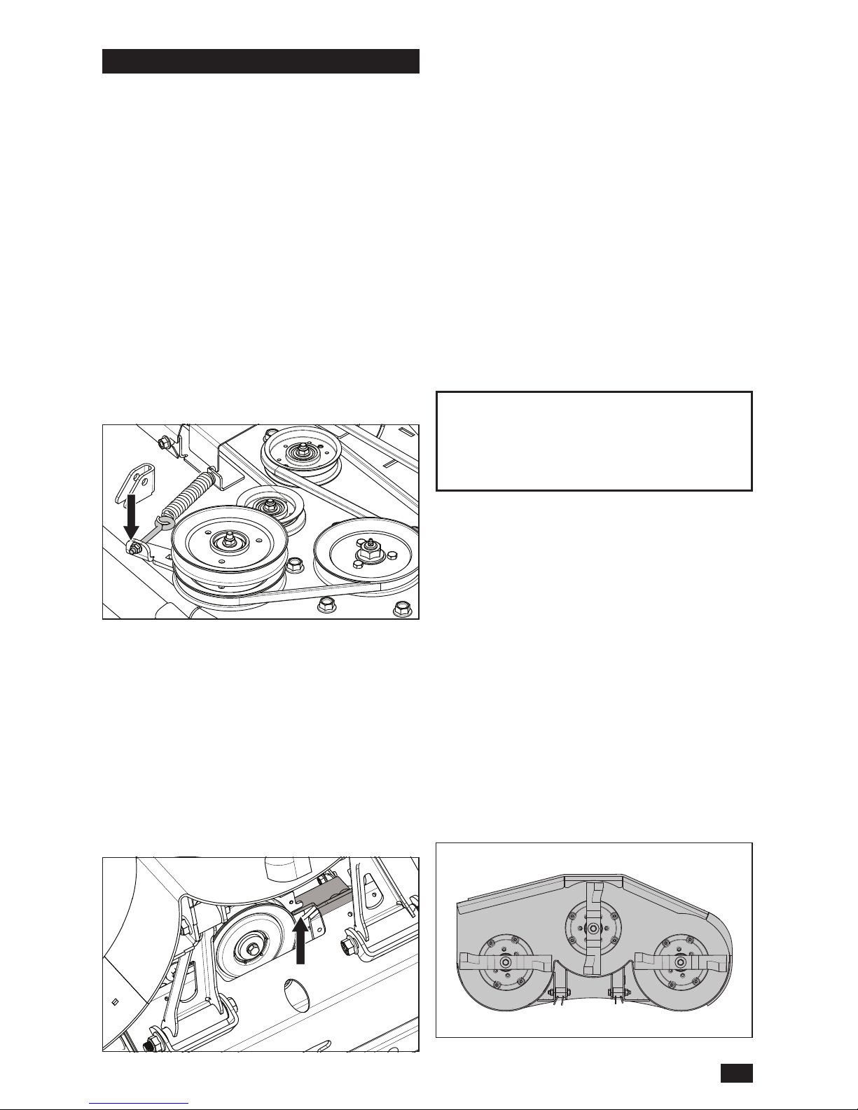
4. Carefully lift the belt over the top of the deck
spindle pulleys.
5. Remove the belt from the deck stacked pulley.
Deck Belt Installation
NOTE: For ease in installing the deck belt, refer to
the routing decal on the cutting deck.
1. Place the belt around all the pulleys except
the center spindle pulley.
2. With a 3/8" breaker bar, shift the idler arm
counter clockwise. When there is enough
slack, slip the belt onto the center spindle
pulley.
3. Check belt routing to make sure it matches
the routing decal and that the belt does not
have twists.
4. Adjust belt tension by turning the eyebolt nut
until there is approximately 6.4–19.0 mm
(1/4"–3/4") of threads showing outside the nut.
5. Belt tension must be set to 13.6–18.1 kg
(30–40 lb).
6. Replace belt shields on the two spindle
housings and secure with fasteners.
7. Install the deck drive belt.
Pump Belt
The belts are not adjustable and need to be
replaced if they begin to slip from wear. Park the
mower on a level surface. Engage the park brake.
1. Remove the deck drive belt.
2. Remove clutch stop to access the belt.
3. Disconnect clutch wire.
4. Remove belt from the engine and pump
pulleys.
Reinstallation
1. Wrap the belt around the engine pulley and
then around the left pump pulley.
2. Route the belt around the inside of the idler
pulley.
3. While holding the idler back, wrap the belt
around the right pump pulley.
4. Replace and secure clutch stop. Reinstall the
deck belt.
5. Check the belt tension. To tighten the
belt, turn the nut on the idler eyebolt. The
recommended belt tension is 12.3 kg (27 lb).
Adjusting the Mower Deck
Leveling Deck
Adjust the deck while the mower is on a level
surface and raised to transport mode (cutting
height of 5"). Make sure the tires are inated to
the correct pressure. See Tire Pressures in this
section. If tires are under or over inated, the
deck cannot be properly adjusted. Faulty mower
deck adjustments will cause an uneven mowing
result.
Four bolts control the height and pitch of the
mower deck. Adjust the deck slightly higher in the
rear.
NOTE: To insure precision in the leveling
procedure, mower deck drive belt must be
installed prior to leveling the deck.
1. Wear heavy gloves. Turn the blade tips to
align with the deck side to side.
Tire Pressures
All tires must be at 103 kPa / 1 bar / 15 psi.
IMPORTANT INFORMATION DO NOT add
a tire liner or foam ll material to the tires.
Excessive loads created by foam lled tires will
cause premature failures.
Only use O.E.M. specied tires.
23
MAINTENANCE
Page 24
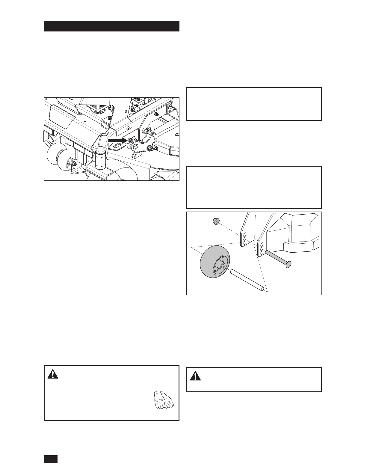
2. Measure from the oor surface up to the
bottom of the blade tip on the discharge side
of the mower deck. Record this measurement.
3. Move to the opposite side; check that
measurement is the same. If adjustment is
required, loosen and adjust the front nuts until
the two side to side measurements are equal.
Retain measurement.
4. Turn the two outer blades to align with
the deck front to rear. Reposition the rear
mounting nuts up or down until the rear blade
tips are positioned 6.4–9.5 mm (1/4"–3/8")
higher in the rear than the center blade tips.
Conrm measurements once again. The blade
tip height must be 0.0–1.6 mm (0"–1/16") side
to side.
In the rear, the blade tips must be 6.4–9.5
mm (1/4"–3/8") higher than the front center
measurement. In the front, blade tips must be
equal from side to side.
NOTE: This will place the mower deck in a
standard measurement position. Depending on
the type of grass being mowed or environmental
conditions, more adjustments may be required to
get the desired cut.
Cutting Blades
To attain the best mowing effect, it is important
that blades are well sharpened and not damaged.
Replace blades that have been bent or cracked
when hitting obstacles.
CAUTION! Blades are sharp. Protect
your hands with gloves and/or wrap blades with
a heavy cloth when handling.
The sharpening of blades should be
carried out by an authorized service
workshop.
Let the service workshop decide whether a blade
with large nicks can be repaired/ground or must
be replaced. Balance the blades after sharpening.
Check the blade mounts.
Anti-scalp Rollers
Anti-scalp rollers keep the deck in the proper
position to help prevent scalping in most terrain
conditions. Do not adjust the rollers to support the
deck.
IMPORTANT INFORMATION Adjust anti-scalp
rollers with the mower on a at level surface. To
avoid deck damage, the anti-scalp rollers must
not be adjusted to support the deck.
Anti-scalp rollers can be set in three positions.
• Upper: 38 mm to 64 mm (1-1/2" to 2-1/2") grass
• Middle: 64 mm to 102 mm (2-1/2" to 4") grass
• Lower: 102 mm to 127 mm (4" – 5") grass
The rollers must be approximately 6.4 mm (1/4")
from the ground. Do not adjust the rollers to
support the deck.
Blade Replacement
1. Remove blade bolt by turning it counter
clockwise.
2. Install new or resharpened blade with the
stamped part number facing towards the
ground/grass (down).
3. Install and tighten blade bolt securely.
4. Torque blade bolt to 122 Nm (90 ft-lb).
IMPORTANT INFORMATION Special blade
bolt is heat treated. Replace with a Husqvarna
bolt if required. Do not use lower grade
hardware than specied.
Park Brake
WARNING! Faulty adjustment will result
in reduced braking and can cause an accident.
Visually check that no damage is found on the
brake arms, cables, or park brake mechanism.
Check that there is sufcient braking action.
1. If the park brake is not performing correctly,
examine the brake arm pivot. With the park
brake disengaged, the brake arm pivot
bracket should have approximately 3.2 mm
(1/8") of play when lifted from the top of the
24
MAINTENANCE
Page 25
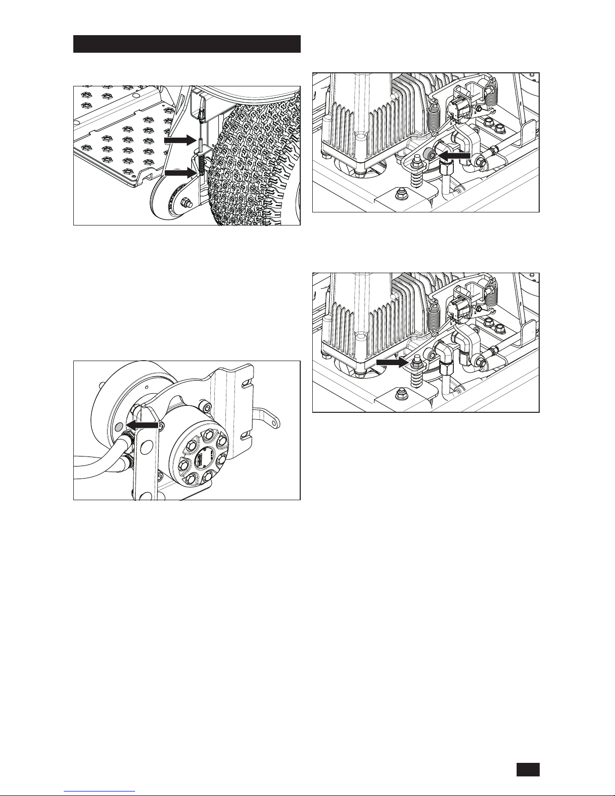
Neutral Adjustment
The back wheels must be raised off of the ground
(or the unit needs to be put on rollers) and the
unit secured so that it cannot roll forwards or
backwards during adjustment.
NOTE: for illustration, the pump covering is not
shown. It does not need to be removed for neutral
adjustment.
1. Raise the wheels of the machine and secure
the unit so it will not roll forward or back during
adjustment.
2. Loosen, but do not remove the two socket
head cap screws located on the pumps at
the front of the unit for the side needing
brake spring. Adjust the brake spring nut as
necessary.
2. If the park brake pivot adjustment is not
sufcient, the brake drum may need
adjustment. With the rear of the unit
supported on jack stands, remove the wheels.
Disengage the brake and set the pumps to
bypass mode. See Moving Machine By
Hand in the Operation section.
3. Remove the rubber plug from the rear of the
brake drum backing plate to access the brake
adjuster.
4. Using a brake spoon, turn the brake adjuster
towards the front of the unit until the brake
begins to engage. The adjuster should then
be backed off three clicks.
adjustment. This will require a 3/8" allen key
(an extension or a long allen key may be
necessary).
3. Start the unit. When unit is running, engage
the OPC lever and release the park brake.
4. Using a 9/16" socket or wrench, adjust the
top nut.
Tighten the nut to bias the unit toward reverse
and loosen the nut to bias it forward. During
adjustment of the nut, bump the controls into
forward and/or reverse and let the controls
snap back to neutral. When the wheel is
stationary at the same time as the operator
controls are in a neutral, tighten the socket
cap screws to 101 ± 20 Nm (75 ± 15 ft-lb).
If the wheel continues to move, further
adjustment is required.
5. Repeat for the opposite side if necessary.
25
MAINTENANCE
Page 26
Cleaning
CAUTION! Always wear eye
protection when cleaning or washing
the mower.
Regular cleaning and washing, especially under
the mower deck, will increase the machine’s lifespan. Make it a habit to clean the machine directly
after use (after it is cooled), before the dirt sticks.
Do not spray water on the top of the mower deck.
Use compressed air to clean the top side of
mower deck. Regularly clean deck and underside
of the deck with normal water pressure. Do not
use a high pressure washer or steam cleaner.
Avoid spraying engine and electrical components
with water.
Do not rinse hot surfaces with cold water. Let unit
cool before washing.
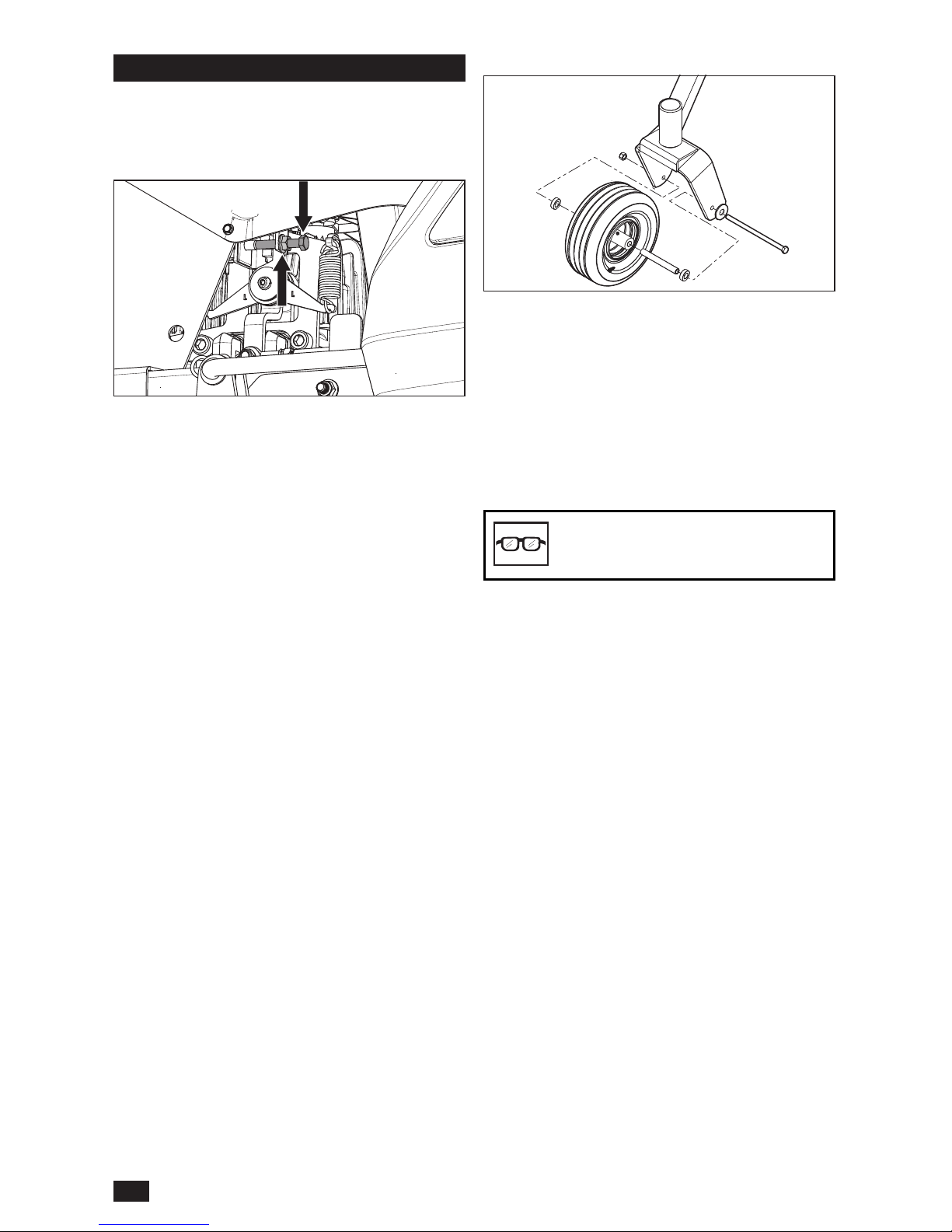
Caster Wheels
Check every 200 hours. Check that wheels rotate
freely.
To replace, remove nut and caster bolt. Pull the
wheel out of the fork. Install in reverse order.
Tighten caster bolt. Torque to 67.8 Nm (50 ft-lb).
NOTE: Tire must rotate freely but axle spacers
must not. If wheels do not rotate freely take the
unit to the dealer for service.
Neutral Switches
1. Make sure the park brake is engaged.
2. With a 1/2" wrench, loosen the jam nuts on
each side of the unit.
3. Adjust the neutral bolt on the left side of the
unit so the plunger on the neutral switch is
ush with the surface of the switch.
4. Go to the right side of the unit and back
the bolt out so the bolt is not contacting the
plunger.
On the right side:
5. Start tightening the right neutral bolt one to
or two turns at a time. Between tightening,
attempt to start the unit, but be sure to keep
ngers or loose articles of clothing away from
the pump fans.
6. Continue tightening the neutral bolt until the
unit attempts to start (it is not necessary to
keep the unit running if it fully starts up).
7. Tighten the neutral bolt an additional half to
full turn and then tighten down the jam nut.
To prevent bending the bracket, do not over
tighten.
On the left side:
8. Loosen the left neutral bolt until it no longer
contacts the plunger on the switch.
9. Tighten the bolt one to two turns and attempt
to start the unit between each adjustment.
When the unit attempts to start, tighten the
bolt one half to one full turn and tighten the
jam nut.
26
MAINTENANCE
Page 27
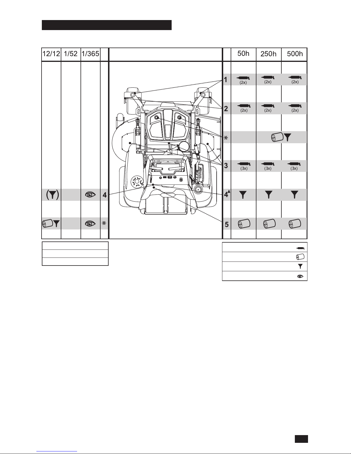
General
Remove the ignition key to prevent accidental
movements during lubrication.
When lubricating with an oil can, it must be
lled with engine oil. When lubricating with
grease, unless otherwise stated, use high grade
molybdenum disulphide grease.
For daily use, the machine must be lubricated
twice weekly.
Wipe away excess grease after lubrication It
is important to avoid getting lubricant on the
belts or the drive surfaces on the belt pulleys.
If this happens, clean them with spirits. If the
belt continues to slip after cleaning, it must be
replaced. Gasoline or other petroleum products
must not be used to clean belts.
Lubrication Schedule
*
Initial hydraulic oil and lter change
performed at 1000 hours. See
Qualied Hydraulic Oils for
recommended lubrication schedule.
p Change engine oil every 50 hours
when operating with a heavy load or at
high ambient temperatures.
12/12 Every year
1/52 Every Week
1/365 Every day
Lubricate with grease gun
Filter change
Oil change
Level check
Qualied Hydraulic Oils
If Parker™ HT-1000 oil is used continually, the oil
and lters must be changed every 1000 hours.
If the following oils are used:
Castrol™ Syntec 5W-50
Amsoil™ AW ISO 68
Shell™ TTF-SB
then oil and lters must be changed every 500
hours after the initial 1000 hour oil and lter
change.
If a premium grade synthetic engine oil with a
minimum viscosity grade of 15W40 is used then
oil and lters must be changed every 250 hours
after the initial 1000 hour oil and lter change.
27
LUBRICATION
Page 28
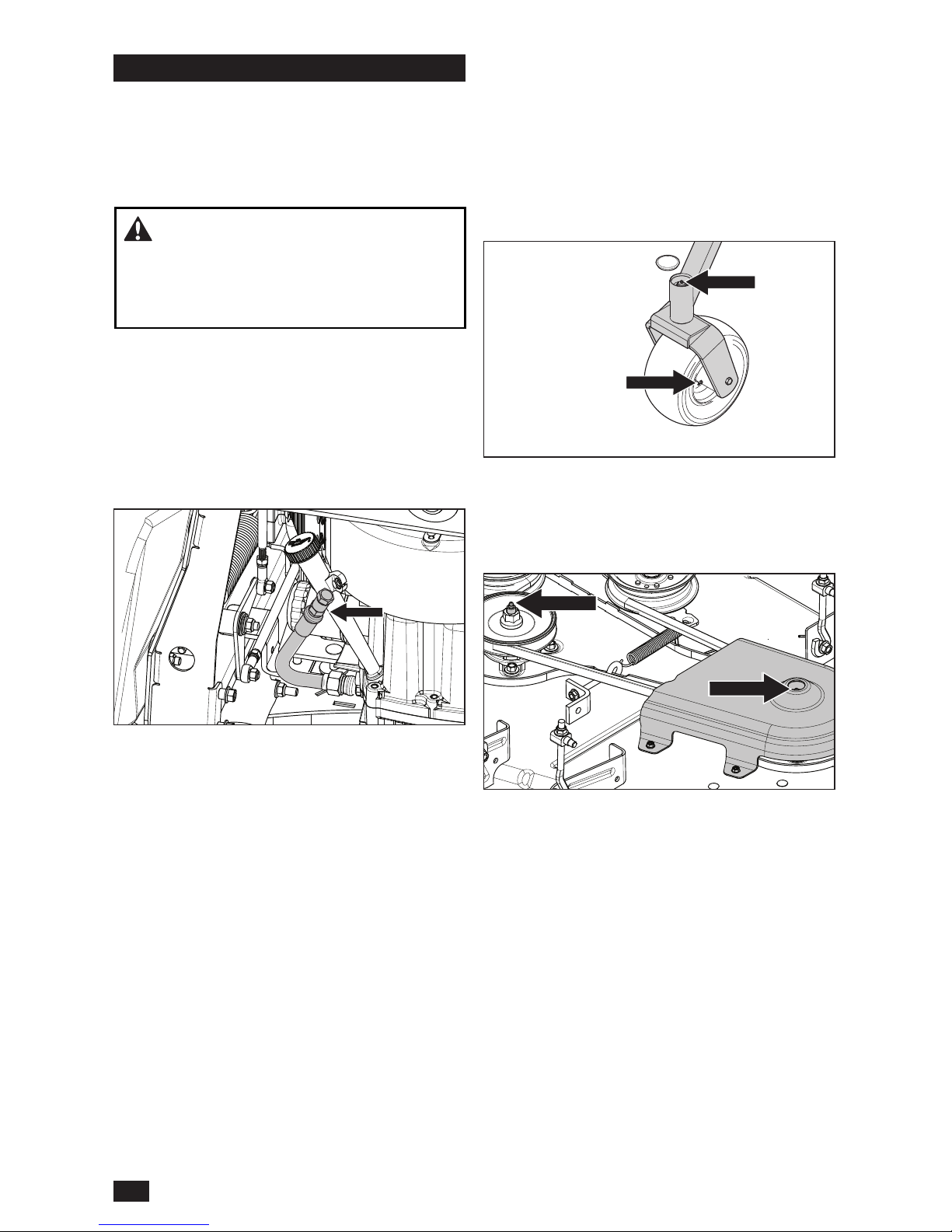
Engine Oil
NOTE: Change the engine oil when the engine
is warm. Refer to the engine owner’s manual
for the correct replacement oil and lter change
recommendations.
1. Park on a level surface. Engage the park
brake.
2. Clean the dirt and debris from the area around
the oil ll cap.
3. Remove the cap/dipstick.
4. Lower or remove the operator cushion to
access the drain hose at the left rear of the
engine.
5. Route the drain hose down through the hole
in the frame.
6. Put an adequately sized container under the
end of the drain hose and remove the oil drain
plug.
7. Let the oil fully drain from the engine.
8. Replace the drain hose plug and tighten
securely.
9. Fill the engine with new oil as recommended
by the engine manufacturer (see the Engine
Manual).
10. Remove the hose from the frame and secure
it into the original position.
11. Check the level with the dipstick.
12. Replace the oil ll cap securely when the oil
level is FULL.
13. Refer to the Service Journal for oil checking
and changing intervals.
WARNING! The engine drain plug is
located close to the mufer. To prevent burns,
the engine should be shut off and allowed to
cool slightly so the engine is still warm but the
surrounding surfaces and oil are not.
Wheels and Blades
Use only good quality bearing grease. Grease
from well-known brand names (petrochemical
companies, etc.) usually maintains a good quality.
Front Wheel Mount
Remove dust cap to expose zerk. Lubricate with
a grease gun until the grease is forced out around
the top washer.
Front Wheel Bearings
Lubricate 3–4 strokes with a grease gun on each
set of wheel bearings.
Deck Spindles
1. Lower the cutting deck completely.
2. A grease gun with a rubber hose must be
used to access the center spindle.
3. Lubricate with a grease gun, 2–3 strokes per
spindle.
28
LUBRICATION
Page 29
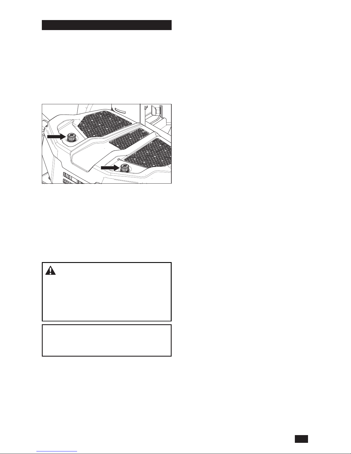
Transaxle Fluid Change
Hydraulic Oil Level Check
Check the oil level in the hydraulic tanks daily
before using the mower. The oil level should be
between the markings on the dipstick. This is the
appropriate level when COLD.
Check all connections, hoses, and tubes for
damage or leaks. Contact an authorized service
workshop if repair or replacement is needed.
Oil and Filters Change
The hydraulic oil and lters must be replaced
every 250 to 1000 hours or once per year,
depending on the type of oil used. See Qualied
Hydraulic Oils in the Lubrication section for a
list of approved oils or refer to the transmission
manufacturers service manual.
Due to the risk of impurities entering the system,
all transmission work should be performed by an
authorized service workshop.
WARNING! Escaping hydraulic oil
under pressure can have sufcient force to
penetrate the skin, causing serious injury. If
injured by escaping uid, see a doctor at once.
Serious infection or reaction can develop if
proper medical treatment is not administered
immediately.
IMPORTANT INFORMATION Use minimal
lubrication and remove excess lubricant so that
is does not come into contact with belts or belt
pulley drive surfaces.
29
LUBRICATION
Page 30

Problem / Cause
Engine will not start
Blade switch is engaged
Steering controls are not locked in the
neutral position
Dead battery
Contamination in the carburetor or fuel line
Clogged fuel lter or fuel line
Ignition system faulty
Neutral out of adjustment
Starter does not turn the engine over
Dead battery
Battery terminal cable contacts are defective
Neutral out of adjustment
Blown fuse
Fault in the starter safety circuit. See Safety
System in the Maintenance Section
Engine runs rough
Faulty carburetor
Clogged fuel lter or jet
Neutral out of adjustment
Choke is engaged with a warm engine
Clogged ventilation valve on the fuel cap
Fuel tank nearly empty
Fouled spark plugs
Rich fuel mixture or fuel-air mixture.
Clogged fuel lter
Wrong fuel type
Water in fuel
Engine seems weak
Clogged fuel lter
Neutral out of adjustment
Fouled spark plugs
Carburetor incorrectly adjusted
Machine vibrates
Blades are loose
Blades are incorrectly balanced
Engine is loose
Engine overheats
Clogged air cleaner
Engine overloaded
Poor ventilation around engine
Defective engine speed regulator
Too little or no oil in the engine
Contamination in the fuel line
Fouled spark plugs
Battery not charging
Battery terminal cable contacts are defective
Charging lead is disconnected
Fault in engine charging system
Mower moves slowly, unevenly, or not at all
Park brake is engaged
Bypass lever on pump is engaged
Transmission drive belt is slack or off
Air trapped in hydraulic system
Mower deck not engaging
Drive belt for the mower deck is loose
Electromagnetic coupling contact is loose
Blade switch is faulty or loose from cable
contact
Blown fuse
Transaxle leaks oil
Damaged seals, housing, or gaskets
Air trapped in hydraulic system
Uneven mowing results
Unequal air pressures in tires
Bent blades
Suspension for the mower deck is uneven
Blades are dull
Driving speed too high
Grass is too long
Grass has collected under the mower deck
30
TROUBLESHOOTING
Page 31

Winter Storage
The machine must be readied for storage at the
end of the mowing season, or if it will not be in
use for more than thirty days.
Fuel allowed to stand for long periods of time
(thirty days or more) can leave sticky residues
that can plug the carburetor and disrupt engine
function.
Fuel stabilizers are an permitted option as
regards to the sticky residues that can occur
during storage.
Add stabilizer to the fuel in the tank or in the
storage container. Always use the mixing ratios
specied by the manufacturer of the stabilizer.
Run the engine for at least ten minutes after
adding the stabilizer so that it reaches the
carburetor. Do not empty the fuel tank and the
carburetor if a stabilizer has been added.
WARNING! Do not store an engine with
fuel in the tank indoors or in poorly ventilated
spaces where fuel vapor can come in contact
with open ames, sparks, or a pilot light
such as in a boiler, hot water tank, clothes
dryer, etc. Handle the fuel with care. It is very
ammable and can cause serious personal
injury and property damage. Drain the fuel
into an approved container outdoors and
store far away from open ame or sources of
ignition. Do not use gasoline for cleaning. Use
a degreaser and warm water.
To ready the machine for storage:
1. Thoroughly clean the machine, especially
under the mower deck. Touch up damage
to the paint and spray a thin layer of oil on
the underside of the mower deck to avoid
corrosion.
2. Inspect the machine for worn or damaged
parts and tighten nuts or screws that may
have become loose.
3. Change the engine oil; dispose of properly.
4. Empty the fuel tanks or add a fuel stabilizer.
Start the engine and let it run until the
carburetor is drained of fuel or the stabilizer
has reached the carburetor.
5. Remove the spark plug and pour about a
tablespoon of engine oil into the cylinder.
Turn over the engine so that the oil is evenly
distributed and then ret the spark plug.
6. Lubricate all grease zerks, joints, and axles.
7. Remove the battery. Clean, charge, and
store the battery in a cool place, but protect
it from direct cold.
8. Store the machine in a clean, dry place and
cover it for extra protection.
Service
When ordering spare parts, please specify the
purchase year, model, type, and serial number.
Always use genuine Husqvarna spare parts.
An annual check-up at an authorized service
workshop is a good way to ensure that the
machine performs its best the following season.
31
STORAGE
Page 32
21 3 4 5 6
21 3 4 5 6
A
B
C
A
B
C
GRY
DGN
DGN
DBL
DBL
DBL
DBL
DBL
DBL
DBL
PUR
WHT
WHT
BLK/WHT
WHT
WHT
WHT
WHT
BLK/WHT
BLK/WHT
BLK/WHT
BLK
BLK
BLK
BLK
BLK
BLK
BLK/WHT
BLK/WHT
BLK
BLK
BLK
BLK
BLK
BLK
BLK
BLK
RED
RED/BLK
RED/BLK
RED/BLK
RED
RED
RED
RED
RED
BLK
GRY/WHT
GRY/WHT
GRY/WHT
GRY/WHT
GRY/WHT
GRY/WHT
RED/BLK
GRY
PUR
PUR
PUR
PUR
ACCESSORY
OUTLET
SEAT SWITCH
(UNOCCUPIED)
LEVER-RIGHT
(IN NEUTRAL)
FUEL
SENDER
ENGINE
ENGINE
GROUND
ELECTRIC
CLUTCH
FUEL
INDICATOR
BLADE SWITCH
(OFF)
HOURMETER
RED/BLK
BRAKE SWITCH
(ON)
LEVER-LEFT
(IN NEUTRAL)
DBL
FUSES
RED/WHT
WHT/BLK
BLK
1
2
3
1
2
3
4
5
B
A
B
S3
7.5 AMP
A4
A3
A
E
A
B
K
FUEL
DIODE
CLUTCH
DIODE
B6
B5
C6
C5
A5
A6
5 AMP
10 AMP
20 AMP
20 AMP
A1
A2
A1
B1
A2
B2
87
30
86
85
NEUTRAL SWITCH
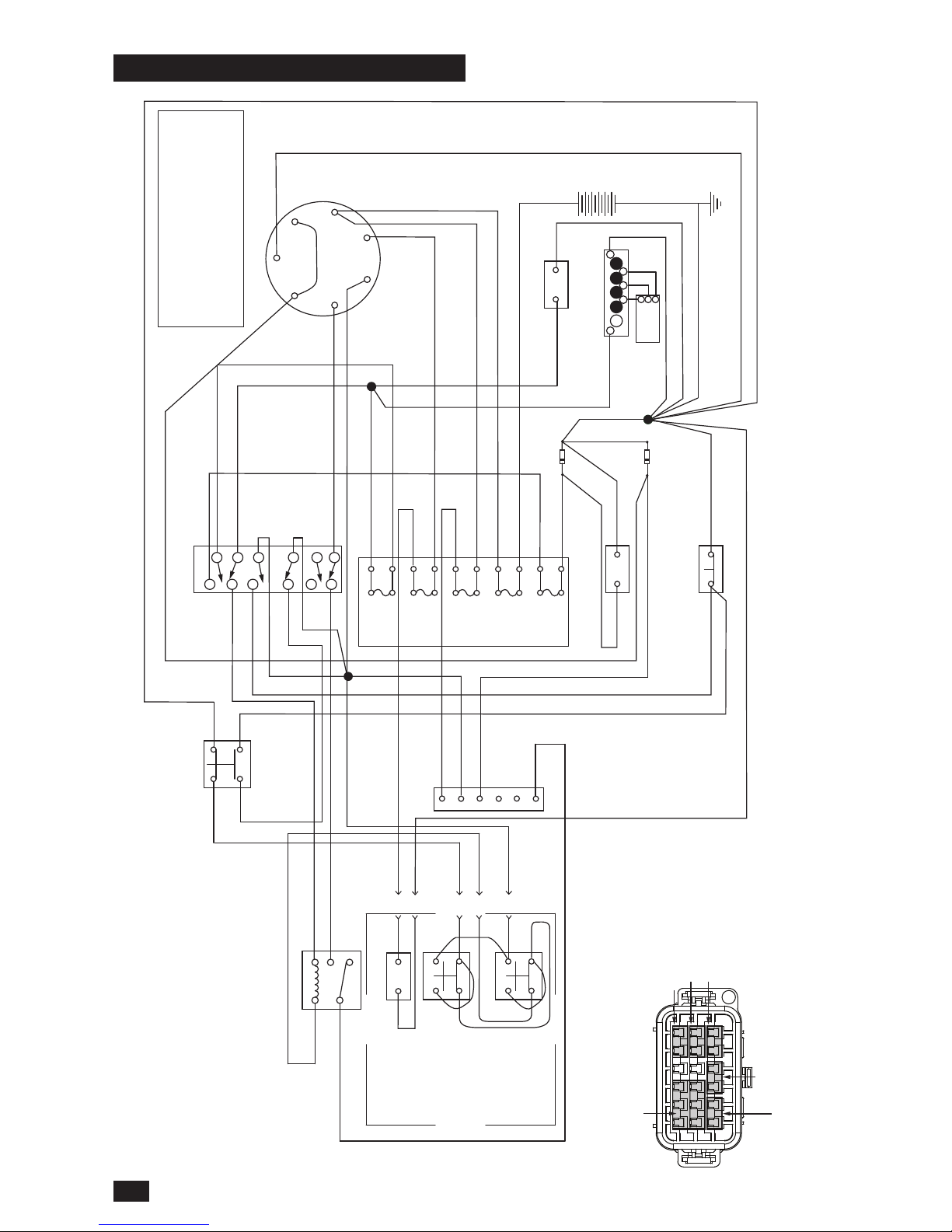
SCHEMATIC (PARKED)
87a
3
1
2
2
4
1
3
2
4
1
3
241
768
5
11
10
12
9
3
2
4
1
6
5
J-3
J-4
J-5
J-6
J-1
J-2
L
Y
M
A
G
S
B
KEY SWITCH POSITIONS
POSITION
3. RUN
2. RUN/LIGHTS
1. OFF
CIRCUIT “MAKE”
B+L
B+L
G+M+L
B+L+S
4. START
NONE
A+Y
NONE
NONE
NEUTRAL - START RELAY
SPDT RELAY
MICRO SERIES - 280
OMRON G8V-1C7T-R-DC12
OR EQUIVALENT
MINI FUSE - 20A (CHRG)
MINI FUSE - 10A (ACCY)
MINI FUSE - 20A (MAIN)
MINI FUSE - 7.5A (CLUTCH)
MINI FUSE - 5A (GAUGES)
32
SCHEMATIC
Page 33
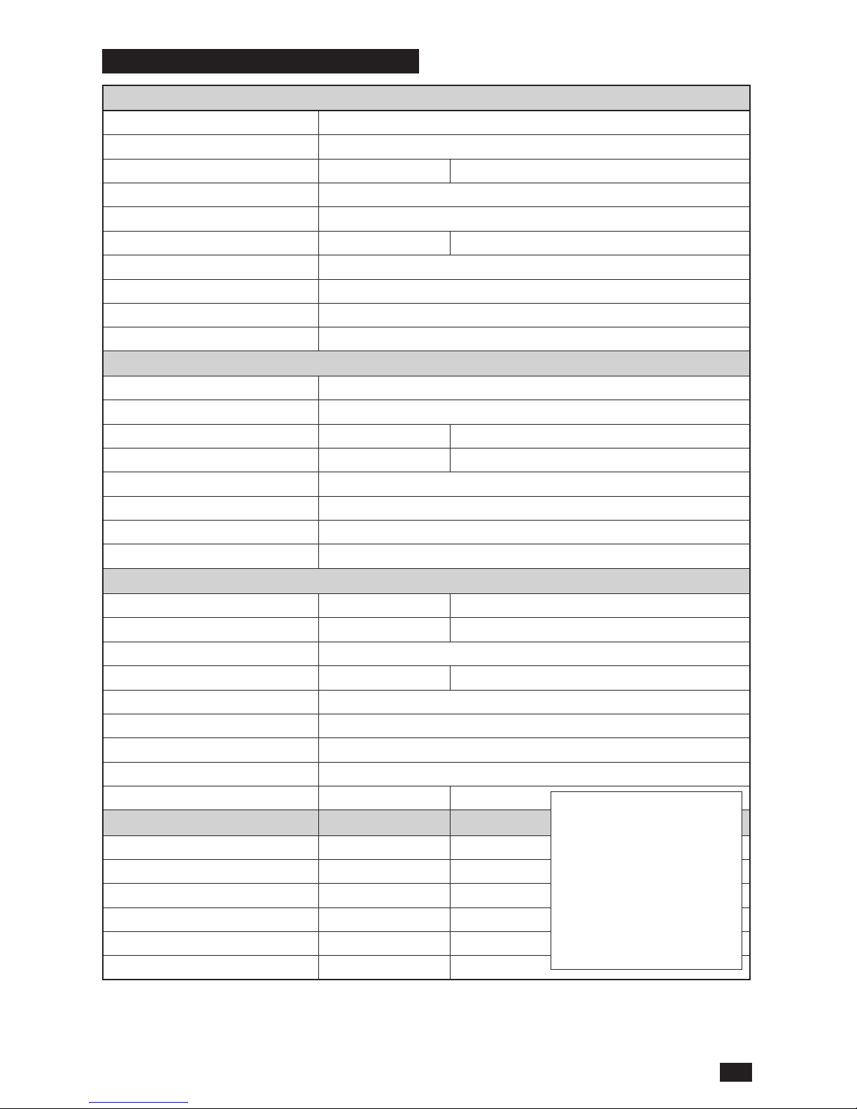
ENGINE
Manufacturer Kawasaki
Type FX751V
Power
18.3 kW
1)
24.5 hp
1)
Lubrication Pressure with oil lter
Fuel Min 87 octane unleaded (Max ethanol 10%, Max MTBE 15%)
Fuel tank capacity 24.6 litres 6-1/2 gallons
Cooling Air cooled
Air lter Heavy duty canister
Alternator 12v 15 amp @ 3600 rpm
Starter Electric
TRANSMISSION
Transmission Parker™ 12cc
Steering control Dual levers, foam gripped
Speed forward 0–15.3 km/h 0–9.5 mph
Speed reverse 0–8.0 km/h 0–5.0 mph
Brakes Mechanical Park Brake
Front caster tires 13 x 6.5
Rear tires, turf pneumatic 20 x 10-10
Tire pressure 103 kPa / 1 bar / 15 psi
FRAME
Cutting Width 137 cm 54"
Cutting Height 3.8 cm – 12.7 cm 1-1/2" – 5"
Number of Blades 3
Blade Length 47 cm 18-1/2"
Anti-scalp roller 2 adjustable
Service Meter Digital
Blade Engagement Ogura GT 2.75 Clutch
Deck Construction 7 gauge fabricated
Productivity
16, 592 m
2
/h
4.1 acres/h
DIMENSIONS
Weight 533 kg 1,176 lb
Base Machine Length 145 cm 57"
Base Machine Height 145 cm 57"
Base Machine Width 120 cm 47"
Overall Width, Chute Up 140 cm 55"
Overall Width, Chute Down 173 cm 68"
1)
The power rating as declared
by the engine manufacturer
is the average gross power
output at the specied
RPM of a typical production
engine for the engine
model measured using
SAE Standards for engine
gross power. Refer to the
engine manufacturer engine
specications.
33
TECHNICAL DATA
Page 34

Standard 1/4" fasteners 9 ft-lb
Standard 5/16" fasteners 18 ft-lb
Standard 3/8" fasteners 33 ft-lb
Standard 7/16" fasteners 52 ft-lb
Standard 1/2" fasteners 80 ft-lb
HEX HEAD CAP SCREWS
The torque values shown must be used as a general guideline
when specic torque values are not given.
U.S. Standard Hardware
Grade SAE Grade 5 SAE Grade 8 Flangelock Screw
w/Flangelock Nut
Size ft-lb Nm ft-lb Nm ft-lb Nm
Shank Size (Diameter in inches,
ne or coarse thread)
1/4 9 12 13 18
5/16 18 24 28 38 24 33
3/8 31 42 46 62 40 54
7/16 50 68 75 102
1/2 75 102 115 156
9/16 110 149 165 224
5/8 150 203 225 305
3/4 250 339 370 502
7/8 378 512 591 801
1-1/8 782 1060 1410 1912
** Grade 5 - Minimum commercial quality (lower quality not recommended)
Metric Standard Hardware
Grade Grade 8.8 Grade 10.9 Grade 12.9
Size ft-lb Nm ft-lb Nm ft-lb Nm
Shank Size (Diameter in millimeters,
ne or coarse thread)
M4 1.5 2 2.2 3 2.7 3.7
M5 3 4 4.5 6 5.2 7
M6 5.2 7 7.5 10 8.2 11
M7 8.2 11 12 16 15 20
M8 13.5 18 18.8 25 21.8 30
M10 24 33 35.2 48 43.5 59
M12 43.5 59 62.2 84 75 102
M14 70.5 96 100 136 119 161
M16 108 146 147 199 176 239
M18 142 193 202 274 242 328
M20 195 264 275 373 330 447
M22 276 374 390 529 471 639
M24 353 478 498 675 596 808
M27 530 719 735 996 904 1226
Engine crankshaft bolt 50 ft-lb
Deck pulley bolts 150 ft-lb
Lug nuts 75 ft-lb
Blade bolt 90 ft-lb
Torque Specications
34
TECHNICAL DATA
Page 35

DELIVERY SERVICE
Action Date, mtr reading, stamp, sign
Charge and connect the battery
r
Adjust the tire pressure of all wheels to 103 kPa (15 psi)
r
Check that the right amount of oil is in the engine
r
Adjust the position of the steering controls
r
Fill with fuel
r
Start the engine
r
Check that there is drive to the two wheels
r
Check mower deck pitch and adjustment
r
Check hydraulic oil level
r
Check:
Safety switch for the park brake
r
Safety switch for the mower deck
r
Safety switch in the steering controls
r
Park brake functionality and adjustment
r
Driving forward
r
Driving backward
r
Engaging the blades
r
Idle speed
r
Engine high idle speed
r
Inform the customer about:
Need and advantages of following the service schedule
r
Need and advantages of leaving the machine for service
r
Effects of service and maintaining a service journal on the
machine’s resale value
r
Application areas for mulching
r
Fill in the sales papers, etc.
Delivery service has
been carried out
No remaining notes
Certied:
35
SERVICE JOURNAL
Page 36

AFTER 10 HOURS
Action Date, mtr reading, stamp, sign
Change the engine oil
r
Inspect hydraulic hoses
r
Inspect hydraulic belt
r
Inspect hydraulic lter
r
Check neutral position
r
Check safety system
r
Check fuel system for leaks
r
Inspect safety guards and shields
r
Check brake adjustment
r
Check hydraulic oil level
r
DAILY SERVICE
Action Date, mtr reading, stamp, sign
Clean debris from mower
r
Check engine oil level
r
Check the tire pressures
r
Check underside of deck
r
Inspect deck pulleys
r
Check/clean the engine’s cooling air intake
r
Check safety system
r
Check fuel system for leaks
r
Inspect safety guards and shields
r
Check brake adjustment
r
Check hydraulic oil level
r
36
SERVICE JOURNAL
Page 37

50-HOUR SERVICE
Action Date, mtr reading, stamp, sign
Clean debris from mower
r
Change the engine oil and lter
r
Check the tire pressures
r
Check underside of deck
r
Inspect deck pulleys
r
Check/clean the engine’s cooling air intake
r
Check safety system
r
Check fuel system for leaks
r
Inspect safety guards and shields
r
Check brake adjustment
r
Check hydraulic oil level
r
37
SERVICE JOURNAL
Page 38

250-HOUR SERVICE
Action Date, mtr reading, stamp, sign
Grease ttings (caster pivots and caster wheels)
r
Inspect frame
r
Inspect throttle and choke cables
r
Inspect hardware
r
Check the tire pressures
r
Change the engine oil and lter
r
Change air lter
r
Inspect spark plug
r
Inspect fuel lter
r
Check engine RPM
r
Clean underside of deck
r
Check blade pitch
r
Grease blade spindles
r
Inspect spindle bearings
r
Inspect deck belt and blades
r
Inspect idler arm bearings
r
Inspect deck idler pulleys
r
Inspect hydraulic lter
r
Inspect hydraulic drive belt
r
Inspect hydraulic hoses
r
Check neutral position
r
Inspect battery connections
r
Check safety system
r
Check fuel system for leaks
r
Inspect safety guards and shields
r
Check brake adjustment
r
Change hydraulic oil and lter
r
38
SERVICE JOURNAL
Page 39

500-HOUR SERVICE
Action Date, mtr reading, stamp, sign
Grease ttings (caster pivots and caster wheels)
r
Inspect frame
r
Inspect throttle and choke cables
r
Inspect hardware
r
Check the tire pressures
r
Change the engine oil and lter
r
Change air lter
r
Inspect spark plug
r
Inspect fuel lter
r
Check engine RPM
r
Clean underside of deck
r
Check blade pitch
r
Grease blade spindles
r
Inspect spindle bearings
r
Inspect deck belt and blades
r
Inspect idler arm bearings
r
Inspect deck idler pulleys
r
Change hydraulic oil and lter
r
Replace hydraulic drive belt
r
Inspect hydraulic hoses
r
Check neutral position
r
Inspect battery connections
r
Load test battery
r
Clean electrical connections
r
Inspect the clutch
r
Check safety system
r
Check fuel system for leaks
r
Inspect safety guards and shields
r
Check brake adjustment
r
39
SERVICE JOURNAL
Page 40

AT LEAST ONCE EACH YEAR
Action Date, mtr reading, stamp, sign
Clean the engine’s cooling air intake
r
Replace the air cleaner’s foam pre-lter
r
Replace the air lter’s paper cartridge
r
Change the engine oil
r
Replace the engine oil lter
r
Change the hydraulic oil and lter
r
Check/adjust the cutting height
r
Check/adjust the park brake
r
Clean/change the spark plugs
r
Inspect spark plug
r
Check the engine valve clearance
r
40
SERVICE JOURNAL
Page 41

41
SERVICE JOURNAL
Page 42

Page 43

Page 44

2018-05-01
 Loading...