

Page 1

TR 650 TERRA 2013
TR 650 STRADA 2013
Workshop Manual Ed. 09-2012
Rev 01
Page 2

Revision Record
Rev. No. Date Page Description
01 30/11/2012 a.1 Change revision.
01 30/11/2012 X.4 Tightening torque figures have been revised.
HUSQVARNA MOTORCYCLES S.R.L. - Varese disclaims all liabilities for any errors or omissions in this manual and
reserves the right to make changes to reect on-going product development. Illustrations in the manual may differ from
actual components. No reproduction in full or in part without written authorisation.
st
edition (09-2012) - Rev. 01
1
Page 3
simbolo
FOREWORD, TABLE OF CONTENTS
TR 650 TERRA 2013 - TR 650 STRADA 2013
Workshop Manual
TR 650 TERRA 2013
TR 650 STRADA 2013
Copyright by
HUSQVARNA MOTORCYCLES S.R.L.
BMW Group
Technical Service
Via Nino Bixio, 8
21024
(Varese) - Italy
tel. ++39 0332 75.61.11
tel. ++39 0332 756 558
www.husqvarna-motorcycles.com
1st edition (09-2012) - Rev. 01
Printed in Italy
MODELS COVERED (from serial number onwards)
1
TR 650 TERRA (43 kW): ZKH0H11A#DV000001
TR 650 TERRA (43 kW - ABS): ZKH0H11C#DV000001
TR 650 TERRA (35 kW - ABS): ZKH0H11D#DV000001
TR 650 STRADA (43 kW - ABS): ZKH0H11E#DV000001
TR 650 STRADA (35 kW - ABS): ZKH0H11F#DV000001
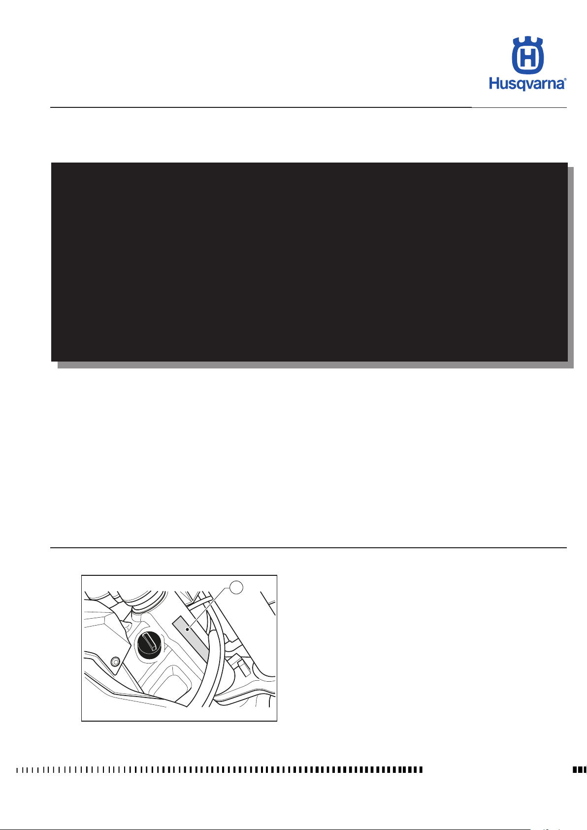
1. Chassis serial number
H11657
Workshop Manual Ed. 09-2012
a.1
Page 4
FOREWORD, TABLE OF CONTENTS
simbolo
TR 650 TERRA 2013 - TR 650 STRADA 2013
Foreword
This publication is designed for use by HUSQVARNA Service Centres to assist authorised personnel in the maintenance
and repair of the models covered in this manual. The technical information provided in this manual is a critical complement to operator training and operators should become thoroughly familiar with it.
This publication is for the exclusive use of those HUSQVARNA technicians who have an adequate basic mechanical
preparation and a good knowledge of the vehicles repair procedures. Thus much information has been intentionally
omitted as it was considered superuous. The technicians must adopt special safety procedures that they will deem
necessary in order to prevent damages to the motorbike, to its components, and to people.
For ease of understanding, diagrams and photographs are provided next to the text.
Notes with special signicance are identied as follows throughout the manual:
Accident-prevention rules for operator and persons working nearby.
Damage to vehicle and/or its components may result from incompliance with relevant instructions.
Additional information concerning the operation covered in the text.
Useful tips
To prevent problems and ensure effective service work, observe the following HUSQVARNA recommendations:
– before repair, evaluate the customer's description of the problem and ask the appropriate questions to clearly identify
problem symptoms;
– diagnose the problem and identify the causes clearly. This manual provides basic background information that must
be supplemented with the operator's expertise and specic training available through HUSQVARNA held at regular
periods;
– plan ahead before starting work: gather any spare parts and tools to avoid unnecessary delays;
– avoid unnecessary disassembly work to get to the part that needs repairing.
Always read the relevant instructions and follow the disassembly sequence outlined in this manual.
Workshop Manual Ed. 09-2012
a.2
Page 5

FOREWORD, TABLE OF CONTENTS
simbolo
TR 650 TERRA 2013 - TR 650 STRADA 2013
Table of Contents
Title Section
Foreword, table of contents ................................................................................. a
Important notices ................................................................................................. b
General information
Maintenance ........................................................................................................B
Troubleshooting
Settings and adjustments ................................................................................... D
General procedures .............................................................................................E
Engine settings and adjustments.........................................................................F
General engine procedures ............................................................................... F1
Cylinder head removal/disassembly .................................................................. F2
Crankcase disassembly.....................................................................................F3
Engine torque gures ........................................................................................F4
Engine parts wear limits ....................................................................................F5
Front suspension .................................................................................................. I
Rear suspension.................................................................................................. J
Brakes ................................................................................................................. L
Electrical system................................................................................................. M
Engine cooling .................................................................................................... N
Tightening torque gures .....................................................................................X
Chassis and wheels.............................................................................................Y
............................................................................................. A
.................................................................................................. C
NOTES
Unless otherwise specied, data and specications apply to all models.
a.3
Workshop Manual Ed. 09-2012
Page 6

Page 7

IMPORTANT NOTICES
TR 650 TERRA 2013 - TR 650 STRADA 2013
Section
b
b.1
Workshop Manual Ed. 09-2012
Page 8
IMPORTANT NOTICES
TR 650 TERRA 2013 - TR 650 STRADA 2013
GENERAL SAFETY WARNINGS
Read these general recommendations carefully before using the vehicle.
Carbon monoxide
Only run the engine in an open or very well ventilated area. If you do work in an enclosed area, make sure you use a fume extraction
system.
Exhaust emissions contain carbon monoxide, a poisonous gas which can cause loss of consciousness and even
death if inhaled.
Parts of the vehicle that become hot
Before working on the engine and the exhaust unit, wait for them to cool down; while the vehicle is running, these parts become very
hot and remain hot for some time after turning off the engine.
Risk of burns - work with caution and wear suitable PPE if necessary.
Fuel
The fuel used to power internal combustion engines is highly ammable and explosive.
Do all fuelling and maintenance operations with the engine switched off and in ventilated areas; do not
smoke and avoid contact between the fuel and naked ames, sparks, etc. that may cause an explosion.
Do not dispose of fuel in the environment.
Keep out of reach of children.
Do not tilt the vehicle excessively since this may cause fuel to leak.
Engine
In some cases, coolant may become inammable and if burnt, produce invisible ames which cause burns.
Do not spill coolant onto hot components like the engine or exhaust pipe, etc. since it may ignite.
During maintenance work, wear latex gloves.
Never leave the coolant in open containers in areas accessible to children and animals since it is toxic.
DO NOT remove the radiator cap when the engine is hot; the coolant is pressurised and may cause scalding.
Engine oil
Do not dispose of oil in the environment since it is highly polluting.
Keep out of reach of children.
Wear latex gloves since prolonged contact with the skin can cause serious damage.
Send used oil to special authorised recyclers in accordance with the legal requirements in force in the country where
the vehicle will be used.
Brake uid
Brake uid is highly corrosive and may damage the rubber and painted parts of the vehicle.
While performing maintenance work, protect your eyes by wearing special goggles and wear protective gloves.
In the event of accidental contact with the eyes, rinse them with plenty of clean, running water and seek medical advice
immediately.
Keep out of reach of children.
Workshop Manual Ed. 09-2012
b.2
Page 9
IMPORTANT NOTICES
TR 650 TERRA 2013 - TR 650 STRADA 2013
Battery
Recharge the battery in well ventilated areas since the battery produces toxic, highly inammable gases when being
recharged; do not smoke or use naked ames or sparks.
The liquid in the battery is highly corrosive. If it comes into contact with the skin, rinse thoroughly with running water.
It is extremely important to protect your eyes because even a small amount of liquid can cause irreversible damage
to the eyes.
If it comes into contact with the eyes, rinse thoroughly with clean, running water and if swallowed accidentally, drink
plenty of water or milk.
In all cases, seek medical advice immediately.
The battery liquid is corrosive and should not be poured onto the painted or rubber parts.
The battery liquid is highly polluting. DO NOT dispose in the environment; at the end of its service life, take the battery
to the special authorised recycling centres in accordance with the legal requirements in force in the country where
the vehicle will be used.
Keep out of reach of children.
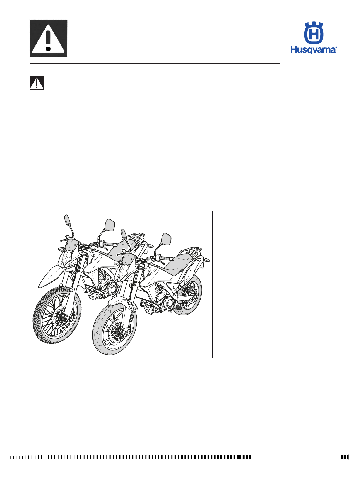
H11658
TR 650 TERRA and TR 650 STRADA models are
STREET LEGAL motorcycles; they are guaranteed
exempt from functional defects and covered with
legal guarantee, as far as the STANDARD CONFIGURATION IS MAINTAINED and the suggested
maintenance table shown in Section "B" is observed.
* In order to maintain the vehicle’s “Guarantee of
Functionality”, the client must follow the maintenance programme indicated in Section B by having
the required maintenance inspections carried out
at authorised HUSQVARNA dealers. The cost for
changing parts and for the labour necessary in order
to comply with the maintenance plan is charged to
the Client. The warranty becomes NULL AND VOID
if the motorcycle is rented.
Notes
Left and right side is determined when seated on
motorcycle.
Z: number of teeth
Unless otherwise specied, data and instructions
apply to all market variants.
b.3
Workshop Manual Ed. 09-2012
Page 10
IMPORTANT NOTICES
TR 650 TERRA 2013 - TR 650 STRADA 2013
RECOMMENDED SHOP PRACTICES
Before disassembling components or before performing repair operations, clean the motorbike removing possible mud, dust, or
foreign bodies.
- Put the vehicle in a well lit area;
- Fasten the vehicle in a steady position so that it cannot overturn; use suitable stands and belts.
- Use suitable equipment for lifting/removing heavy parts.
- Use appropriate keys (not pliers) to loosen/tighten nuts and screws.
- When loosening or tightening nuts or bolts, always begin with the bigger ones or from the centre. Tighten to the specied torque
and follow a cross pattern or a dedicated pattern as outlined in the relevant section.
- Always mark any parts or positions that might be confused upon assembly.
- Use special tools where specied.
- Clean thoroughly the removed components before retting them
- During the reassembly, make sure that the bearings turn freely without obstruction or without getting stuck, otherwise replace
them
- Always replace the seals, the sealing rings, the split pins, the screws with damaged thread, and the self-locking nuts with new
parts.
- Use genuine HUSQVARNA parts and the recommended lubricant brands.
- At the end of a repair or periodic maintenance, test the vehicle before delivering it to the customer.
Electrical parts
- Disconnect the electrical component connectors by pressing the special safety hooks.
- Make sure that inside the connector there is no dirt or rust; if need be, clean them with an air jet or suitable products.
- Make sure that the cables are correctly seamed to the connector terminals.
- When you reconnect the connectors, ensure the correct coupling.
Do not disconnect the connectors by pulling the electrical cables.
- Technical Bulletins might contain more up-to-date setting data and procedures than this manual. Be sure to read them.
Where not specied, ret the previously removed components following the procedures in the reverse order with
respect to the removal.
Workshop Manual Ed. 09-2012
b.4
Page 11
GENERAL INFORMATION
TR 650 TERRA 2013 - TR 650 STRADA 2013
Section
A
A.1
Workshop Manual Ed. 09-2012
Page 12
GENERAL INFORMATION
TR 650 TERRA 2013 - TR 650 STRADA 2013
Sommario
Engine ..........................................................................................................A.3
Timing system ..............................................................................................A.3
Lubrication ....................................................................................................A.3
Ignition ..........................................................................................................A.3
Fuel system ..................................................................................................A.3
Primary drive ................................................................................................A.3
Clutch ...........................................................................................................A.3
Transmission ................................................................................................A.3
Transmission ratio ........................................................................................A.3
Secondary drive............................................................................................A.3
Final ratios ....................................................................................................A.4
Chassis .........................................................................................................A.4
Front suspension
Rear suspension...........................................................................................A.4
Front brake ...................................................................................................A.4
Rear brake
Wheels..........................................................................................................A.4
Tyres
.............................................................................................................A.4
Table for lubrication, supplies .......................................................................A.5
Electrical components location .....................................................................A.5
Dimensions, weight, capacity
..........................................................................................A.4
....................................................................................................A.4
.......................................................................A.6
Workshop Manual Ed. 09-2012
A.2
Page 13
GENERAL INFORMATION
TR 650 TERRA 2013 - TR 650 STRADA 2013
Engine
Single cylinder, 4 stroke engine with four valves
Cooling .............................................................................liquid and electric fan
Bore ...................................................................................... 3,937 in (100 mm)
Stroke ..................................................................................... 3,268 in (83 mm)
Displacement ..................................................................... 39,787 in3 (652 cm3)
Compression ratio ..................................................................................12,3:1
Starting .................................................................................................. electric
Type of fuel ............................................................. unleaded fuel 95ROZ/RON
Timing system
Double overhead camshaft chain operated; 4 valves
Valve clearance (with engine cold)
Intake ............................................................0,009 ÷ 0,011 in (0,23 ÷ 0,28 mm)
Exhaust........................................................ 0,015 ÷ 0,017 in (0,38 ÷ 0,43 mm)
Lubrication
Dry sump with tank integrated in the chassis and cartridge oil lter.
Ignition
Electronic with adjustable advance (digital control)
Spark plug type................................................................ “NGK” MAR9A-J-G06
Spark plug electrode gap....................................................0,024 in (± 0,004 in)
0,6 mm (± 0,1 mm)
Fuel system
Electronic injection feed
Primary drive
Drive gear on crankshaft ............................................................................ Z 37
Driven gear on clutch housing .................................................................... Z 72
Transmission ratio ....................................................................................1.946
Clutch
Multidisc in oil bath with mechanical control
Transmission
With front couplings always engaged
Transmission ratio
1st gear......................................................................................... 2.750 (33/12)
2nd gear ....................................................................................... 1.750 (28/16)
3rd gear ........................................................................................ 1.313 (21/16)
4th gear ........................................................................................ 1.045 (23/22)
5th gear ........................................................................................ 0.875 (21/24)
Secondary drive
Transmission sprocket ............................................................................... Z 16
Rear wheel sprocket ................................................................................... Z 47
Transmission ratio ....................................................................................2.938
Drive chain dimensions ..........................................................520KR0 112 links
A.3
Workshop Manual Ed. 09-2012
Page 14
GENERAL INFORMATION
TR 650 TERRA 2013 - TR 650 STRADA 2013
Final ratios
1st gear....................................................................................................15.722
2nd gear ..................................................................................................10.005
3rd gear ....................................................................................................7.506
4th gear .....................................................................................................5.974
5th gear .....................................................................................................2.898
Chassis
Single frame, in round, rectangular and ellipsoidal steel pipes; rear steel chassis
Front suspension
Upside down type hydraulic fork..............................ø 1.81 in (46 mm) fork legs
Wheel travel ........................................................................... 7.48 in (190 mm)
Rear suspension
Hydraulic monoshock (adjustment of spring preload and rebound hydraulic
damping)
Wheel travel ........................................................................... 7.48 in (190 mm)
Front brake
Ø 11,811 in (300 mm) xed disc with hydraulic control and oating calliper
Rear brake
Ø 9,449 in (240 mm) oating wave disc with hydraulic control and oating calliper
Wheels
TR 650 STRADA
Front
.................................................................................in light alloy: 2.5”x19”
.....................................................................................in light alloy: 3”x17”
Rear
TR 650 TERRA
Front ................................................ with spokes and aluminium rim: 1.85”x21”
Rear
....................................... with spokes and aluminium rim: 3”x18” (no ABS)
with spokes and aluminium rim: 3”x17” ( ABS)
Tyres
TR 650 STRADA
Front ............................................................................... 110/80 R19” M/C 59 V
................................................................................ 140/80 R17” M/C 59 V
Rear
Cold tyre pressure (Rider only)
Front
................................................................................2.2 kg/cm2 (31.29 psi)
................................................................................. 2.0 kg/cm2 (28.45 psi)
Rear
Cold tyre pressure (Rider and passenger)
Front ................................................................................2.2 kg/cm2 (31.29 psi)
Rear
................................................................................. 2,5 kg/cm2 (35.56 psi)
TR 650 TERRA
....................................................................90/90 21” M/C 54 H TL (ABS)
Front
90/90 21” M/C 54 S (no ABS)
Rear ........................................................................140/80 17” M/C 59 H (ABS)
140/80 18” M/C 70 S (no ABS)
Cold tyre pressure (Rider only)
Front ................................................................................2.0 kg/cm2 (28.45 psi)
Rear
................................................................................. 2.5 kg/cm2 (35.56 psi)
Cold tyre pressure (Rider and passenger)
Front ................................................................................2,0 kg/cm2 (28.45 psi)
................................................................................. 2,8 kg/cm2 (39.82 psi)
Rear
Workshop Manual Ed. 09-2012
A.4
Page 15
GENERAL INFORMATION
TR 650 TERRA 2013 - TR 650 STRADA 2013
Table for lubrication, supplies
Engine, gearbox and primary drive
lubricating oil................................ CASTROL POWER1 RACING SAE 10W-50
Engine coolant ..................................... CASTROL MOTORCYCLE COOLANT
Brake uid ...........................................CASTROL RESPONSE SUPER DOT 4
Grease lubrication ....................................................CASTROL LM GREASE 2
Secondary drive chain lubrication................ CASTROL CHAIN LUBE RACING
Electric contact protection ......................CASTROL METAL PARTS CLEANER
Electrical components location
The ignition system includes the following elements:
- Generator on the inner side of R.H. crankcase half cover;
- Electronic ignition coil with integrated spark plug cap positioned on cylinder head;
- Electronic control unit on rear chassis under saddle;
- Spark plug on cylinder head;
- Starter motor in front of cylinder block;
- Solenoid starter on rear chassis under saddle;
- Potentiometer on throttle body;
- Voltage regulator on right-hand side of engine;
- Neutral position sensor on right-hand side of engine.
The electrical system includes the following elements:
- 12V - 10Ah battery in the central part;
- Turning indicator asher integrated in the digital instrument;
- Fuel pump relay, main relay and fan on rear chassis under saddle;
- Electric fan;
- Auxiliary fuses on rear chassis under saddle; two 30A main fuses on solenoid starter;
- Coolant temperature sensor on cylinder head;
- Lambda sensor;
- Headlamp with H4-12V-55/60W HD halogen bulb and 12V-5W LL parking light bulb;
- LED tail light with stop light bulb;
- 12V-RY10W turning indicator bulbs;
- Fuel pump inside the tank.
- Multifunction digital instrument.
A.5
Workshop Manual Ed. 09-2012
Page 16
GENERAL INFORMATION
TR 650 TERRA 2013 - TR 650 STRADA 2013
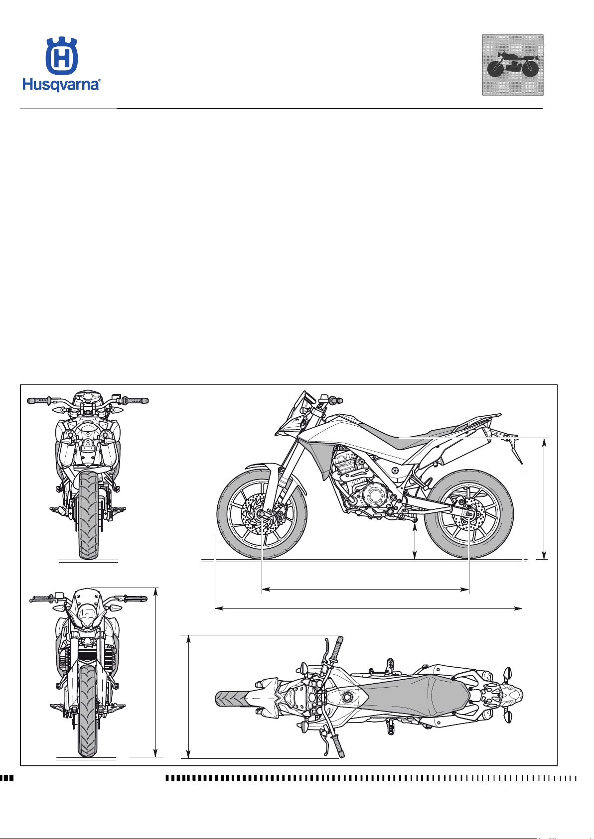
Dimensions, weight, capacity
Wheelbase ............................................................................................................................55,055 in (1500 mm)
Total length (STRADA) ........................................................................................................ 88,504 in (2248 mm)
Total length (TERRA)............................................................................................................ 89,252 in (2267 mm)
Overall width ...........................................................................................................................34,843 in (885 mm)
Max. height (STRADA) ......................................................................................................... 47,441 in (1205 mm)
Max. height (TERRA) ............................................................................................................. 48,15 in (1223 mm)
Saddle height (STRADA).........................................................................................................33,858 in (860 mm)
Saddle height (TERRA) ..............................34,449 in (875 mm) (no ABS - 18”) / 34,055 in (865 mm) (ABS - 17”)
Minimum height off ground (STRADA) .....................................................................................9,843 in (250 mm)
Minimum height off ground (TERRA) ............. 10,472 in (mm 266) (no ABS 18”) / 10,118 in (257 mm) (ABS 17”)
Weight, without fuel (STRADA). ..............................................................................................390,218 lb (177 kg)
Weight without fuel. (TERRA) ......................................................................................................383,604 (174 kg)
Fuel tank capacity including reserve
Fuel reserve................................................................................... approx. 0,55 Imp. Gall. / 0,66 U.S. Gall. / 2.5 l
Coolant tank capacity ........................................................................... 0,255 Imp. Gall. / 0,306 U.S. Gall. / 1.16 l
Oil and oil lter replacement
Topping up oil between minimum and max. level ................................. 0,055 Imp. Gall. / 0,066 U.S. Gall. / l 0.25
.................................................................... 0,44 Imp. Gall. / 0,528 U.S. Gall. / 2.0 l
......................................................... 3,08 Imp. Gall. / 3,698 U.S. Gall. / l 14
Workshop Manual Ed. 09-2012
C
D
1500 mm
A
B
885 mm
H11659
A.6
Page 17
MAINTENANCE
TR 650 TERRA 2013 - TR 650 STRADA 2013
Section
B
All tightening indicated with the letter "S" (Safety) in section X "Tightening Torques" must be checked at each service
or whenever other maintenance/repair work is carried out.
Workshop Manual Ed. 09-2012
B.1
Page 18
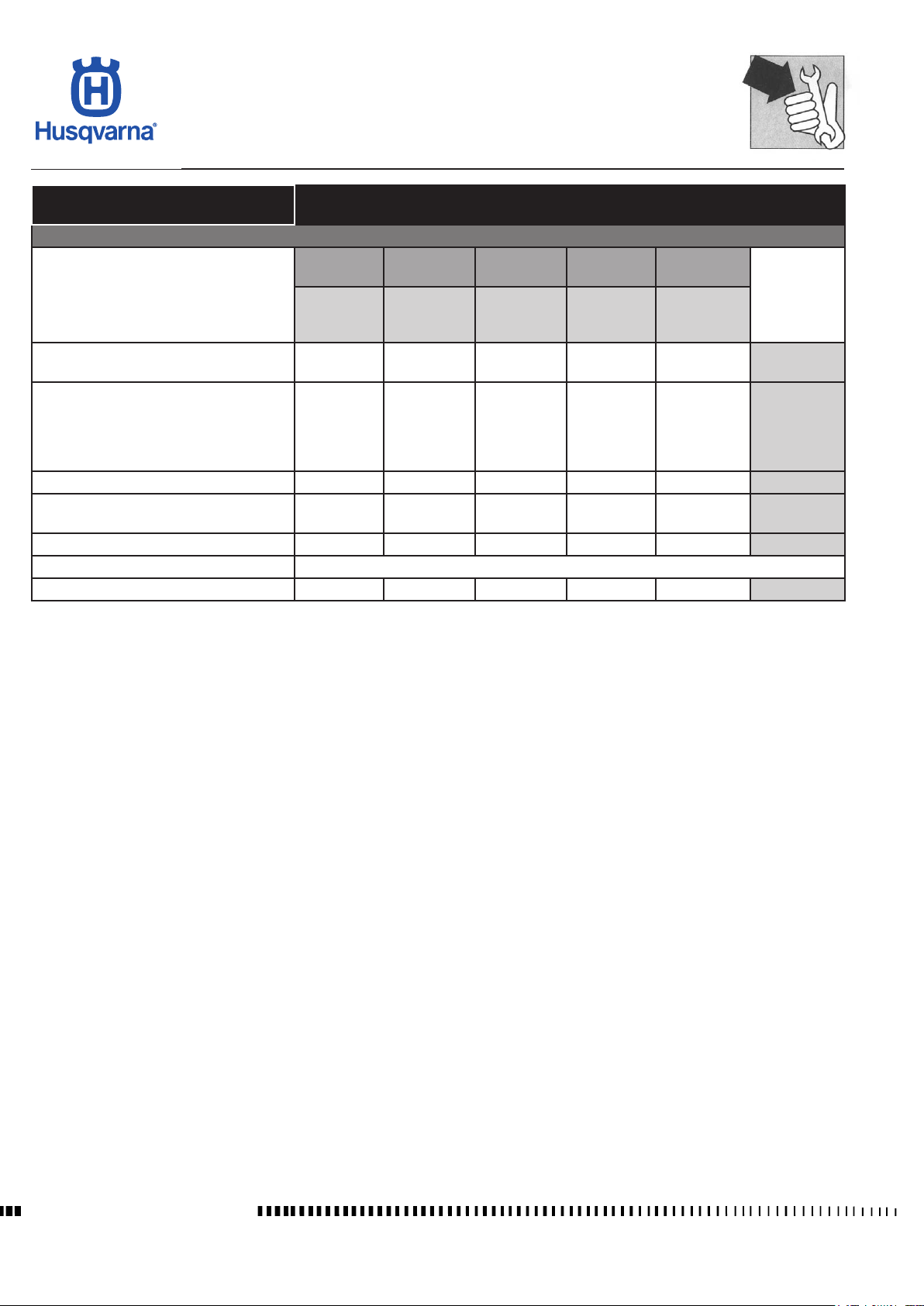
MAINTENANCE
TR 650 TERRA 2013 - TR 650 STRADA 2013
TR 650 STRADA
TR 650 TERRA
SERVICE
COUPON
AFTER
THE FIRST
1.000 Km
Check engine oil level
Replace engine oil together with oil lter,
clean magnetic plug
Check / adjust valve play C/R C/R C/R C/R
Replace spark plugs
Oil lter (on oil return pipe from chassis) P/S P/S
Replace coolant EVERY 2 YEARS
Check / adjust clutch play C/R C/R C/R C/R C/R
C S S S S
S S S S S
(TO BE CARRIED OUT AT THE HUSQVARNA DEALER)
10.000 Km
SCHEDULED MAINTENANCE CHART
ENGINE
SERVICE
COUPON
EVERY
SERVICE
COUPON
EVERY
20.000 Km
S S
SERVICE
COUPON
EVERY
30.000 Km
SERVICE
COUPON
EVERY
40.000 Km
EVERY
1.000 Km
EVERY
10.000 Km
or
ONCE A
YEAR
EVERY
20.000 Km
C: Check
S: Change
R: Reset
Workshop Manual Ed. 09-2012
B.2
Page 19
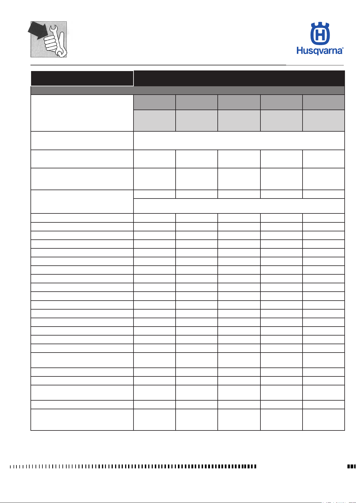
MAINTENANCE
TR 650 TERRA 2013 - TR 650 STRADA 2013
TR 650 STRADA
TR 650 TERRA
(TO BE CARRIED OUT AT THE HUSQVARNA DEALER)
SCHEDULED MAINTENANCE CHART
CHASSIS
SERVICE
COUPON
AFTER THE
FIRST
SERVICE
COUPON
EVERY
10.000 Km
SERVICE
COUPON
EVERY
20.000 Km
SERVICE
COUPON
EVERY
30.000 Km
SERVICE
COUPON
EVERY
40.000 Km
1.000 Km
Check and lubricate secondary chain
Lubricate the secondary drive chain at least once every 1,000 km.
If used on dusty or wet roads, do this more frequently
Second.Drive chain: check tension and
wear
C/L C/L/S C/L/S C/L/S C/L/S
Check front/rear sprockets for wear: if necessary, replace along with the secondary
C/L/S C/L/S C/L/S C/L/S
drive chain
Air lter S S
If the vehicle is used in very dusty conditions/on very dusty roads, reduce this service
to 10,000 km
Safety tightening check
C/R C/R C/R C/R C/R
Transmission cables and controls C/R/L C/R/L C/R/L C/R/L C/R/L
Steering bearings and steering clearance C/R C/R C/R C/R
Emptying the intake silencer hose C/P C/P C/P C/P
Brake discs C/S C/S C/S C/S
Brake pad wear C/S C/S C/S C/S
Front fork (oil change) S S
General vehicle operation C C C C C
Braking systems (check pipes) C/R C/R C/R C/R C/R
Cooling system (check level) C/S C/S
Lights / warnings C/R C/R C/R C/R C/R
Safety switches C/R C/R C/R C/R
Brake uid
Coolant
(1)
(3)
C/R C/R C/R C/R C/R
C/R C/R C/R C/R C/R
Checking battery charge level C/R C/R C/R C/R
Tyres: Pressure / Wear C/R C/R C/R C/R
Wheels (checking spoke tension - terra
version)
C/R C/R C/R C/R
Control unit diagnosis C/R C/R C/R C/R C/R
Side stand C/R/L C/R/L C/R/L C/R/L
Checking function and clearance of accelerator cable
Fuel hoses
(2)
C/R C/R C/R C/R
C/S
Check cooling-water tubes and water
pump for condition and leakage / replace
C C C C
if necessary
S: Change
L: Lubricate
P: Clean
R: Reset
B.3
C: Check
(1):
Replace every 2 years
(2):
Replace every 4 years
(3):
Replace every year
Workshop Manual Ed. 09-2012
Page 20

Page 21

TROUBLESHOOTING
TR 650 TERRA 2013 - TR 650 STRADA 2013
Section
C
C.1
Manuale d'officina Ed. 09-2012
Page 22
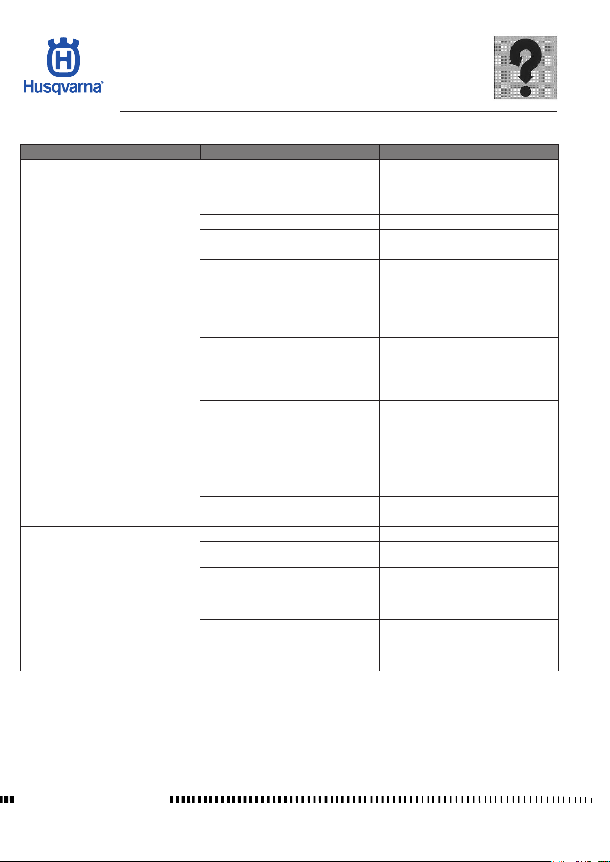
TROUBLESHOOTING
TR 650 TERRA 2013 - TR 650 STRADA 2013
ENGINE
Trouble Possible causes Remedy
Ignition switch not in ON position Switch ignition switch to position ON
Engine-stop-switch on OFF position Switch to position ON
Starter motor does not operate or does not
turn engine over
Engine turns over but does not start engine
or starts hard
Engine runs irregularly at idle
Flat battery, loose or rusty connections
Ignition circuit in short-circuit Check ignition circuit
Starter motor defect Replace starter motor
Spark plugs loose Tighten spark plugs
Spark plugs not according to specications
or defective
Spark plugs fouled or wet Clean or exchange
Battery nearly discharged, starting rpm
too low
Fuel supply inadequate
Valve clearance below specication
Valve timing incorrect Adjust position of camshaft gears
Ignition coil or ignition cable defective Check / replace
Ignition unit defective, ignition timing incorrect
Cylinder gasket defective Exchange cylinder head gasket
Valves and valve guides worn or imperfect
valve seat
Piston rings and/or cylinder bore worn Exchange piston rings and/or cylinder
Engine oil too heavy (winter operation) Exchange engine oil
Excessive spark plug electrode gap Exchange spark plug
Valve clearance below specication
Intake coupling not tightened or damaged
Ignition unit defective, ignition timing incorrect
Valves leaking Rework valve seats
For other possible causes see also "Engine
starts over but does not start engine or
starts hard"
Check/replace battery and check connections, check charging system
Replace spark plug
Check/replace battery and check connections, check if battery is charged by
generator
Check fuel tank if empty
Check / replace fuel supply pipes, fuel pump,
fuel pressure sensor and injectors
Adjust valve clearance according to speci-
cation
Check / replace crank position trigger and
ECU
Exchange valves, rework valve seats or
exchange cylinder head
Adjust valve clearance according to speci-
cation
Tighten intake socket or exchange if necessary
Check / replace crank position trigger and
ECU
Manuale d'officina Ed. 09-2012
C.2
Page 23
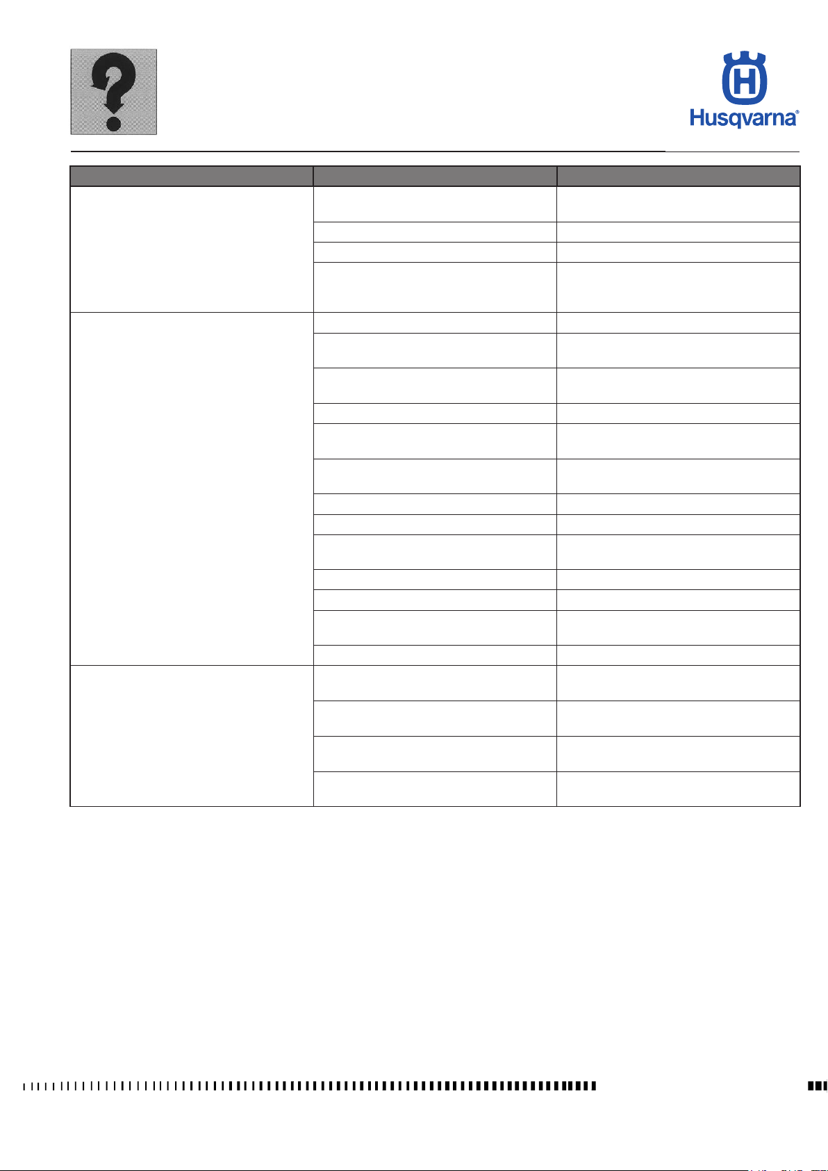
TROUBLESHOOTING
TR 650 TERRA 2013 - TR 650 STRADA 2013
Trouble Possible causes Remedy
Check fuel pressure sensor, fuel pump and
fuel supply
Replace spark plug
Adjust valve clearance according to speci-
cation
Check / replace ignition coil
Check / replace crank position trigger and
ECU
Check fuel pressure sensor, fuel pump and
fuel supply
Exchange piston rings and/or cylinder
Use fuel of specied octane number (min.
ROZ 95)
Replace spark plug
Check / replace intake socket and intake
system
Check / replace crank position trigger and
ECU
Engine runs irregularly at higher speed
Engine has no or insufcient performance
Engine knocks or pings
Fuel pressure too low
Leak air Check / replace intake socket
Camshafts worn Check and replace if necessary
For other possible causes see also "Engine
starts over but does not start engine or
starts hard"
Leak air, intake system leaking Check / replace intake socket
Spark plugs not according to specications
or defective
Valve clearance not according specication
Valve timing incorrect Adjust position of camshaft gears
Ignition coil supplies insufcient ignition
voltage
Ignition unit defective, ignition timing incorrect
Valves leaking Exchange valves, rework valve seats
Clutch slipping See remedies "clutch is slipping".
Fuel pressure too low
Air lter dirty Exchange
Exhaust system defective Exchange
Excessive Blow-by gases, Piston rings and/
or cylinder bore worn
Engine oil not according to specications Exchange engine oil
Fuel of too low octane number
Spark plugs not according to specications
or defective
Leak air, intake system leaking
Ignition unit defective, ignition timing incorrect
C.3
Manuale d'officina Ed. 09-2012
Page 24
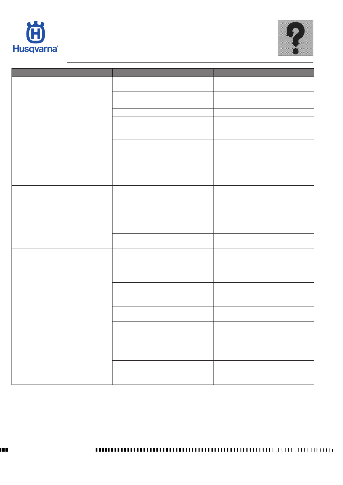
TROUBLESHOOTING
TR 650 TERRA 2013 - TR 650 STRADA 2013
Trouble Possible causes Remedy
Not enough coolant in cooling system, cooling system leaking, air in cooling system
Cooling fan motor defective Replace cooling fan motor
Not enough engine oil in the engine Rell oil
Radiator dirty Clean radiator
Faulty thermostatic valve Replace
Engine overheats
Engine temperature is too low Faulty thermostatic valve Replace
Engine produces excessive blue smoke or
engine uses too much oil
Engine vibrates
Engine oil quantity increases
Low or no engine oil pressure
Ignition unit defective, ignition timing incorrect
Water pump, water pump drive defective
Oil pump or oil pump drive defective, oil
circuit blocked
Cylinder head gasket defective Exchange cylinder head gasket
Leak air Check / replace intake socket
Too much oil in the engine (oil in the airbox) Drain engine oil
Cylinder head gasket leaking Exchange cylinder head gasket
Valve stem seals leaking Exchange valve stem seals
Oil diluted with fuel / Piston rings and/or
cylinder bore worn
Oil diluted with fuel / motocycle is only used
in short distances (cold engine)
Engine xation into frame loose Tighten engine xation
Bearing or bearing seat worn Replace bearing or worn component
Oil diluted with fuel / motocycle is only used
in short distances
Oil diluted with fuel / Piston rings and/or
cylinder bore worn
Not enough engine oil in the engine Rell oil
Pressure regulating piston blocked (bypass
valve stuck in opened position)
Oil pump and/or oil pump drive defective
Oil pump worn Replace oil pump
Oil diluted with fuel / Piston rings and/or
cylinder bore worn
Oil diluted with fuel / motocycle is only used
in short distances
Oil sieve / oil lter dirty/blocked Clean / replace oil sieve and replace oil lter
Rell coolant, check system under pressure
Check / replace crank position trigger, ECU
and sensors
Repair water pump, check and renew water
pump drive
Exchange oil pump or oil pump gears,
clean oil circuit
Exchange piston rings and/or cylinder
Use motorcycle at long distances in between
Use motorcycle at long distances in between
Exchange piston rings and/or cylinder
Check/replace pressure regulating piston
Check / replace oil pump and/or oil pump
drive
Exchange piston rings and/or cylinder
Use motorcycle at long distances in between
Manuale d'officina Ed. 09-2012
C.4
Page 25
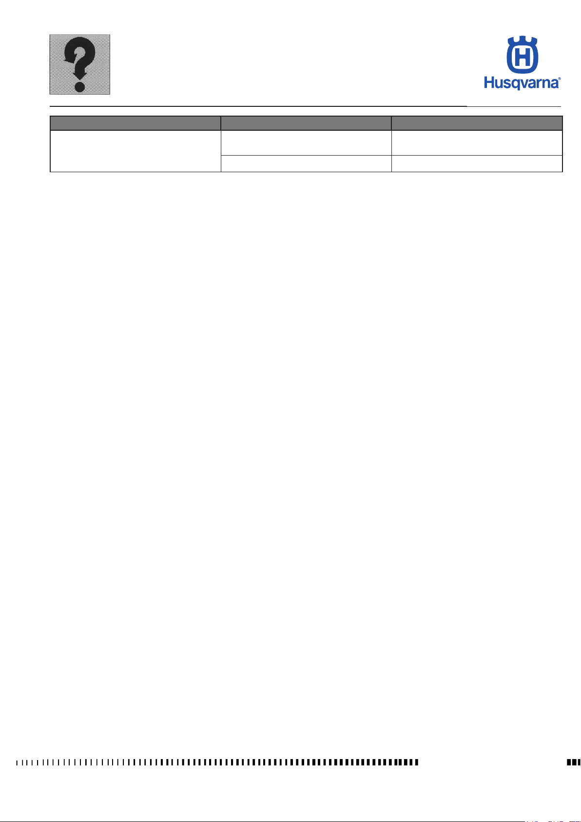
TROUBLESHOOTING
TR 650 TERRA 2013 - TR 650 STRADA 2013
Trouble Possible causes Remedy
High engine oil pressure
Pressure regulating piston blocked (bypass
valve stuck in closed position)
Oil circuit blocked Clean oil ducts
Check/replace pressure regulating piston
C.5
Manuale d'officina Ed. 09-2012
Page 26
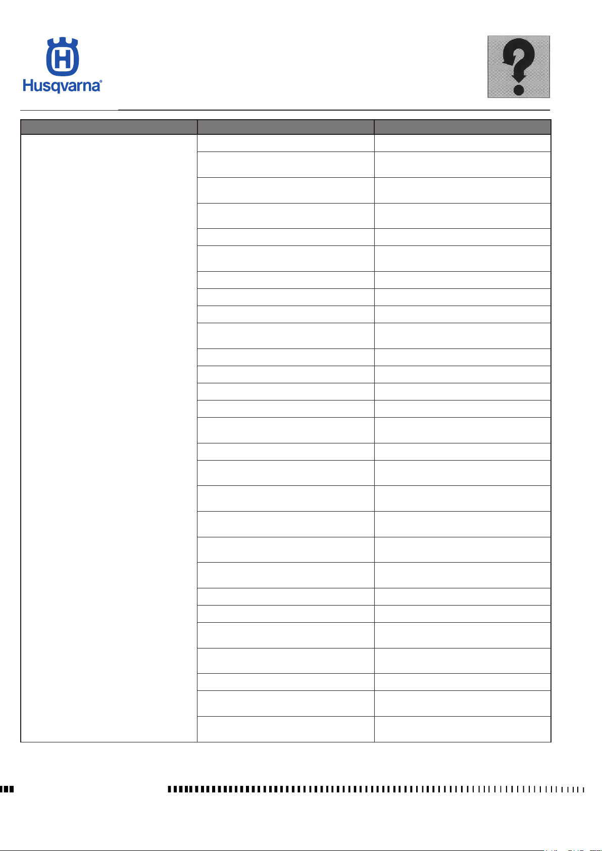
TROUBLESHOOTING
TR 650 TERRA 2013 - TR 650 STRADA 2013
Trouble Possible causes Remedy
Noise is heard when the engine is started:
Sprag clutch, sprag clutch housing or freewheel gear worn
Teeth of starter motor and/or starter drive
gears worn
Chain tensioner does not work
Noise seems to come from the valve train:
Excessive valve clearance
Chain tensioner does not work Replace chain tensioner
Camshaft or brackets of camshaft worn Replace camshafts and/or cylinder head
Camshaft drive worn or loose Tighten or replace camshaft gears
Camshaft chain, chain guide or chain tension guide worn
Noise seems to come from the piston:
Replace Sprag clutch, sprag clutch housing
or freewheel gear
Replace starter motor and/or starter drive
gears
Noise disappears after the engine is started
when oil pressure is available
Adjust valve clearance according to speci-
cation
Replace camshaft chain, chain guide or
chain tension guide
Engine excessively noisy
Piston or cylinder worn Replace piston or cylinder
Piston pin bore or piston pin worn Replace piston pin bore or piston pin
Piston rings broken or ring grooves worn
The noise seems to come from the
crankshaft, countershaft or crankcase:
Bearings of crankshaft or conrods worn Replace the crankshaft
Worn needle bushing and/or balancer shaft
bearings and/or balancing connecting rod
Noise seem to come from the clutch or
clutch side:
Friction plates (hammer heads) and/or
clutch drum worn
Excessive or insufcient backlash of the
teeth of the primary drive gears
Clutch drum, clutch hub or pressure plate
worn
Bearing of clutch gear worn Replace primary drive assy.
Disk springs of primary drive assy. worn Replace primary drive assy.
Springs and spring retainers of primary
drive assy. Worn
Noise with clutch engaged - ball bearing of
the pressure plate worn
Noise seem to come from the gearbox:
Tooth anks of the gearbox gears worn
Ball bearing of gearbox shafts and/or needle
bearings of gears worn
Replace piston rings broken or ring grooves
Replace the balancer shaft
Replace friction plates and /or clutch drum
Replace primary drive assy.
Replace clutch drum, clutch hub or pressure plate
Replace springs and spring retainers
Replace ball bearing
Check gears and gear shafts, replace if
necessary
Replace bearings
Manuale d'officina Ed. 09-2012
C.6
Page 27
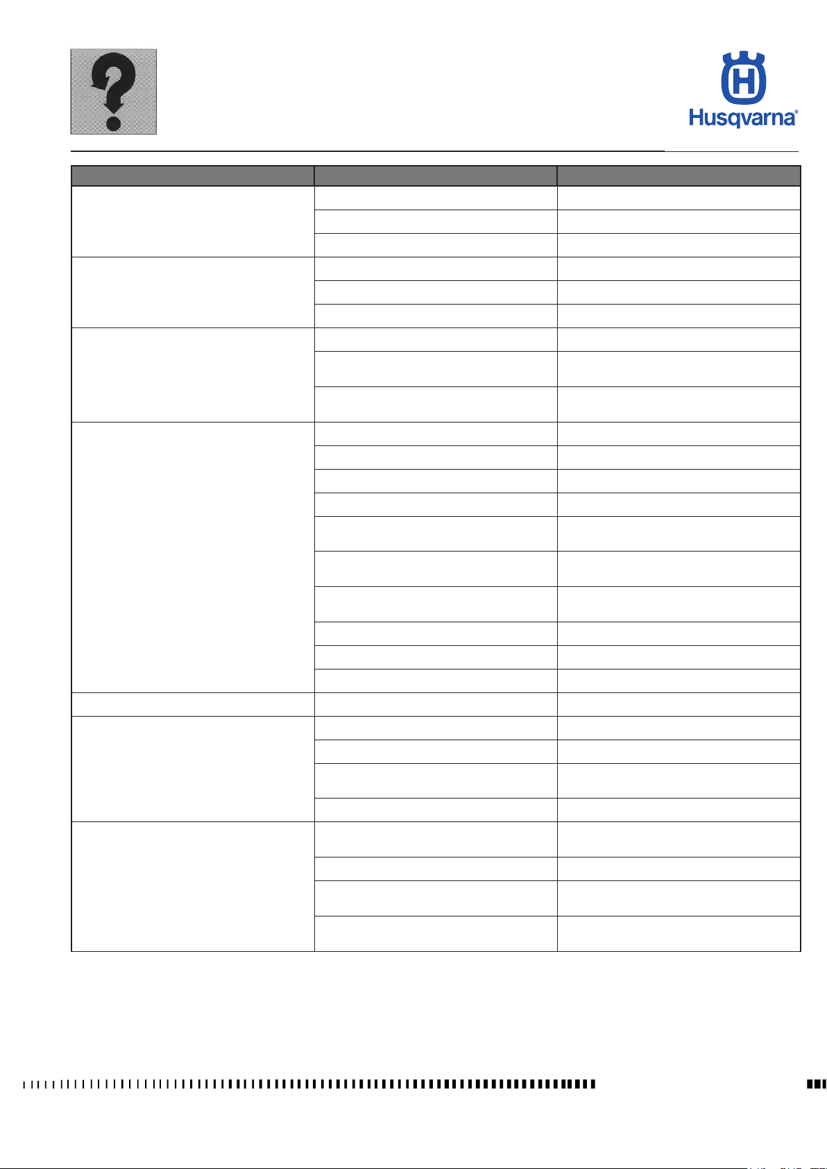
TROUBLESHOOTING
TR 650 TERRA 2013 - TR 650 STRADA 2013
Trouble Possible causes Remedy
Fatigue of clutch springs Replace clutch springs
Clutch slips
Clutch disengages unsatisfactorily
The clutch drags
Gears do not engage or gears jump out at
start or at abrupt acceleration
Clutch plates worn or warped Replace clutch plates
Engine oil not according to specications Exchange engine oil
Engine oil not according to specications Exchange engine oil
Clutch plates warped Exchange clutch plates
Clutch plates stuck together Clean or exchange
Clutch plates worn or warped Replace clutch plates
Guide slots for friction plates in clutch drum
are worn
Guide slots for steel plates in clutch hub
are worn
Gearshifting action incomplete Always actuate gearshift lever till stop
Gearshift lever incorrectly adjusted Correct position of gearshift lever
Fastener of gearshift lever loose Tighten fastener
Gearshift lever bent Replace gearshift lever
Function of index lever or index spring
imperfect
Adjustment of gearshift pawl incorrect
Engagement teeth and/or windows of gearbox gears badly worn
Gearshift forks are worn or bent Exchange gearshift forks
Replace clutch drum
Replace clutch hub
Check index lever and index spring and
exchange if necessary
Check and adjust pawl wich spring, exchange if necessary
Exchange gears
Gearbox gears are worn or damaged Exchange gearshift gearbox gears
The clutch does not disengage See "Clutch disengages unsatisfactorily"
Gears can be shifted only noisily Clutch does not disengage See "Clutch disengages unsatisfactorily"
Spark plugs not according to specications Replace spark plug
Spark plugs loose Tighten spark plugs
Spark plugs overheated, burnt or dirty
The generator does not charge the battery
Intake socket not tight or leaking
Fuel supply system defective Check and replace if necessary
Battery faulty, loose or corroded connections
Rectier regluator defective Replace rectier regluator
Break in current, short circuit or earthing of
stator windings
Break in cables or short circuit, connections loose
Tighten intake socket or exchange if necessary
Check/replace battery and check connections
Replace stator
Check and replace if necessary
C.7
Manuale d'officina Ed. 09-2012
Page 28
TROUBLESHOOTING
TR 650 TERRA 2013 - TR 650 STRADA 2013
CHASSIS
Trouble Cause Remedy
Insufcient tyre pressure Inate
Handlebar turns hard
Handlebar vibration
Damping is too hard
Damping is too soft
(Front / rear) wheel shakes
Rear suspension is noisy
Poor braking (front and rear)
Bearing adjuster ring nut or steering stem
nut overtightened
Bent steering stem Replace bottom yoke
Worn or seized steering bearings Replace
Bent fork legs Replace
Bent front wheel axle Replace
Warped chassis Replace
Bent front wheel rim Replace
Worn front wheel bearings Replace
Improperly balanced wheel Balance
Too much oil in fork legs Remove excess oil
Fork oil viscosity too high Change
Overinated tyres Deate
Improperly set rear shock absorber Adjust
Insufcient oil in fork legs Top up
Fork oil viscosity too low Change
Weak fork springs Replace
Weak rear shock absorber spring Replace
Improperly set rear shock absorber Adjust
Bent wheel rim Replace
Worn wheel hub bearings Replace
Wheel axle nut loose Tighten
Worn rear swinging arm bearings Replace
Improperly balanced wheel Balance
Worn shock absorber joints Replace
Shock absorber faulty Replace
Air in brake system Bleed
Insufcient uid in tank Top up
Worn brake pad and/or disc Replace
Damaged disc Replace
Adjust
Manuale d'officina Ed. 09-2012
C.8
Page 29
TROUBLESHOOTING
TR 650 TERRA 2013 - TR 650 STRADA 2013
ELECTRICAL SYSTEM (see also Section M)
Trouble Cause Remedy
Dirty air lter Clean
Spark plug fouls easily
Spark plug electrodes overheat
Generator does not charge or is not
providing enough charge
Generator overcharges battery Voltage regulator faulty Replace
Battery does not hold charge
Starter motor does not start or slips
Worn piston rings Replace
Worn piston or cylinder liner Replace
Spark plug electrode gap too close Adjust
Wrong heat rating Replace with recommended spark plug
Cables running to voltage regulator improperly connected or shorted
Voltage regulator faulty Replace
Faulty generator Replace
Battery terminals dirty Clean
Faulty generator Replace
Faulty battery Replace
Battery is at Charge
Control on R.H. switch faulty Replace
Starter relay faulty Replace
Starter motor faulty Repair or replace
Worn starter gears Replace
Worn or damaged freewheel rollers Replace freewheel
Ignition key not recognised Check control unit key immobiliser
Connect correctly or replace
C.9
Manuale d'officina Ed. 09-2012
Page 30

Page 31

SETTINGS AND ADJUSTMENTS
TR 650 TERRA 2013 - TR 650 STRADA 2013
Section
D
D.1
Workshop Manual Ed. 09-2012
Page 32

SETTINGS AND ADJUSTMENTS
TR 650 TERRA 2013 - TR 650 STRADA 2013
Sommario
Saddle removal.............................................................................................D.3
Removal of central upper cover....................................................................D.4
Side panel removal .......................................................................................D.4
Throttle cable adjustment .............................................................................D.5
Throttle control..............................................................................................D.5
Throttle position adjustment .........................................................................D.5
Front brake control .......................................................................................D.5
Position adjustment ......................................................................................D.5
Front brake lever adjustment and uid level check ......................................D.6
Clutch control................................................................................................D.6
Position adjustment ......................................................................................D.6
Clutch control lever distance adjustment ......................................................D.7
Clutch free play adjustment
Rear brake pedal free play adjustment.........................................................D.8
Rear brake uid level check .........................................................................D.8
Oil level check
Engine oil replacement and cartridge lter replacement ..............................D.9
Replacement of cartridge lter....................................................................D.10
Filling
..........................................................................................................D.11
Coolant level check ....................................................................................D.11
Coolant replacement
Air lter check
Chain tension adjustment
Lubricating the chain
Suspension ................................................................................................D.15
Shock absorber spring preload adjustment
Rebound shock absorber hydraulic damping adjustment...........................D.16
Fork adjustment .........................................................................................D.16
Fuel supply hose inspection and replacement
Exhaust system check ................................................................................D.17
Idle speed adjustment
Checking and adjustment of valve clearance
..............................................................................................D.9
.............................................................................................D.13
..........................................................................D.7
..................................................................................D.12
...........................................................................D.14
..................................................................................D.14
................................................D.15
...........................................D.16
................................................................................D.18
.............................................D.18
Workshop Manual Ed. 09-2012
D.2
Page 33
SETTINGS AND ADJUSTMENTS
TR 650 TERRA 2013 - TR 650 STRADA 2013
Saddle removal
2
H11660
2
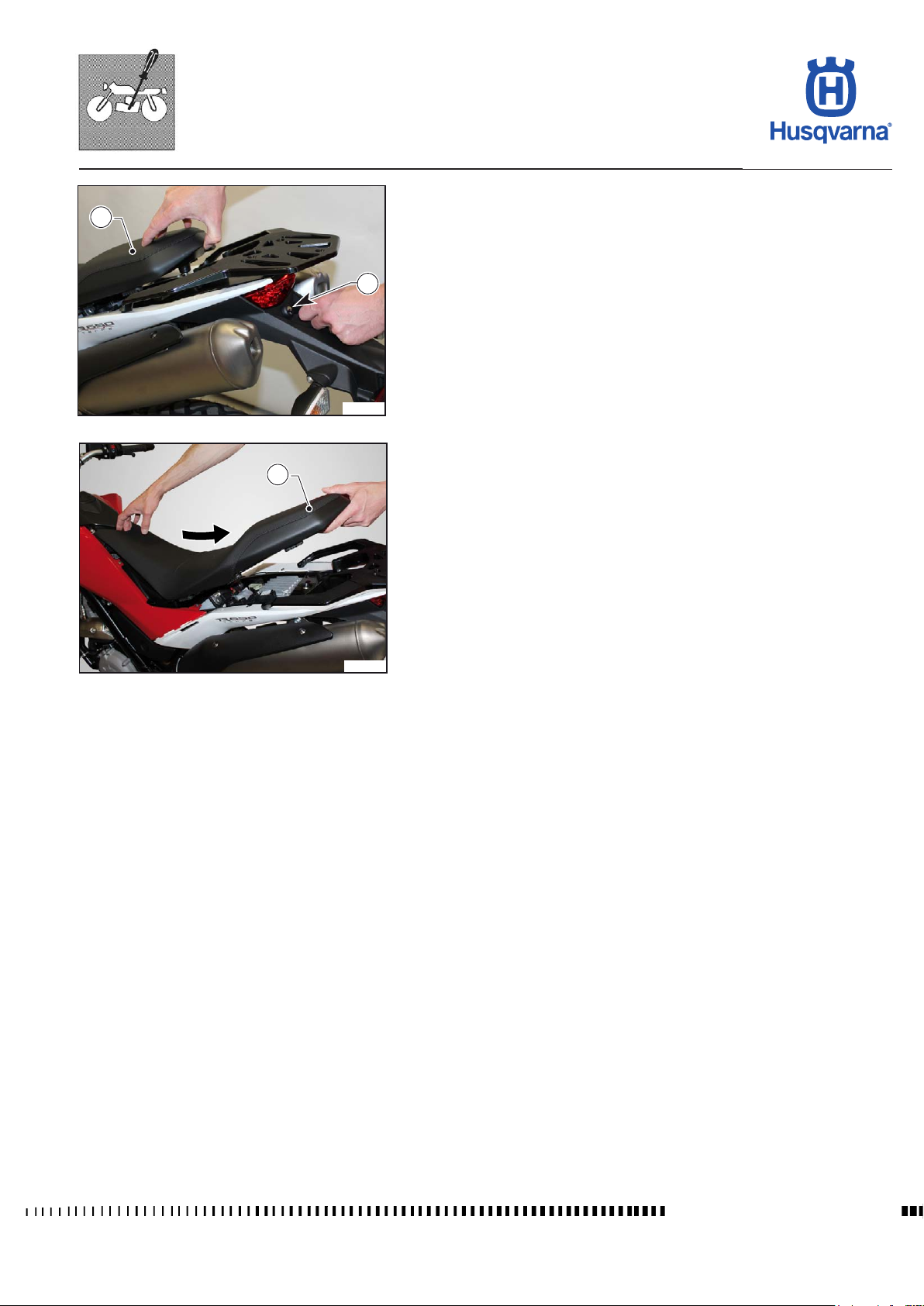
To remove the saddle proceed as follows:
- Insert the key in the lock (1) positioned in the rear part of the motorcycle;
- turn the key clockwise to release the saddle (2), and then lift it and pull it out
towards the rear, releasing it from the front fastener.
To t the saddle back on, fasten it at the front and then press the rear until the
1
fastening "Click" is heard.
H11661
D.3
Workshop Manual Ed. 09-2012
Page 34
SETTINGS AND ADJUSTMENTS
TR 650 TERRA 2013 - TR 650 STRADA 2013
Removal of central upper cover
1
1
2
H11662
1
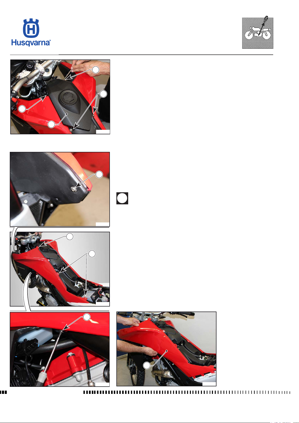
- Unscrew the four screws (1) that fasten the cover (2) and remove it.
1
Side panel removal
- Remove the saddle as described in the relevant paragraph.
- Remove the upper cover as described in the relevant paragraph.
- Unscrew the ve screws (1) and remove the left-hand side panel (2) from
its ttings.
- Repeat to remove the right-hand side panel.
When retting, rst insert the rear and then the front ttings.
H11664
1
1
H11663
1
Workshop Manual Ed. 09-2012
H11665
2
H11666
D.4
Page 35
SETTINGS AND ADJUSTMENTS
TR 650 TERRA 2013 - TR 650 STRADA 2013
4
2 mm
(0,8 in.)
1
2 mm
(0,8 in.)
4
3
2
H11667
H11668
Throttle cable adjustment
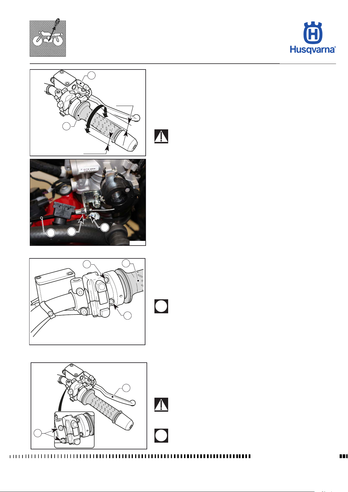
To check the correct adjustment of the throttle control cable, operate as follows:
- remove the reservoir and the lter box as outlined in the relevant sections;
- turn throttle twistgrip (1) and make sure that there is a clearance of approx.
2 mm (0.08 in);
- if this does not work, unlock the check nut (2);
- work on the nut (3) until you have about 2 mm clearance (0.08 in.);
- tighten check nut (2).
- reassemble all parts, in the reverse order compared to disassembly.
Operation with damaged throttle cable could result in an unsafe
riding condition.
When throttle control cables (4) are replaced, adjust new cables as previously
explained.
Throttle control
2
1
The throttle twistgrip (1) is located on the right-hand side of the handlebar:
Throttle position adjustment
The position of the control on the handlebar can be adjusted by loosening the
two retaining screws (2).
Do not forget to tighten the screws (2) after adjusting.
2
H11669
Front brake control
The brake control lever (1) is located on the right-hand side of the handlebar.
Position adjustment
1
The position of the control on the handlebar can be adjusted by loosening the
two retaining screws (2).
After adjustment, turn the handlebar as far as possible to the right
and make sure that the lever does not touch the bodywork
A stop switch, during the braking action, causes the stop light on the tail light
to come on.
2
Do not forget to tighten the screws (2) after adjusting.
H11670
D.5
Workshop Manual Ed. 09-2012
Page 36
2
MIN
SETTINGS AND ADJUSTMENTS
TR 650 TERRA 2013 - TR 650 STRADA 2013
Front brake lever adjustment and uid level check
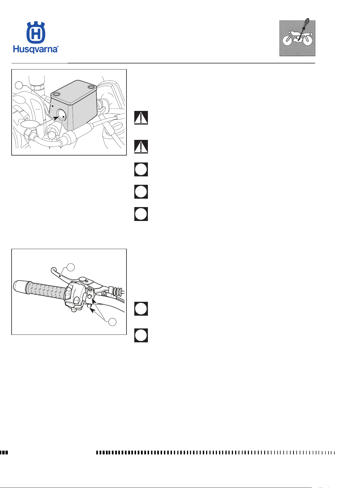
The level of the uid in the master cylinder reservoir must never be below the
minimum level visible through the inspection sight glass (1) on the side of the
master cylinder (2) body.
A decrease of the fuel level will let air into the sustem, hence an extension of
the level stroke.
If the brake lever feels mushy when pulled, there may be air in the
brake line or the brake may be defective: CHECK THE BRAKING
SYSTEM (see Section "L").
1
H11671
Too much brake lever free play may reduce braking action: CHECK
BRAKE PAD THICKNESS (see Section "L").
Do not spill brake uid onto any painted surface or lens (for example
lights lens).
Do not mix two brands of uid. Completely change the brake uid
in the brake system if you wish to switch to another uid brand.
Brake uid may cause irritation. Avoid contact with skin or eyes. In
case of contact, ush thoroughly with water and call a doctor if your
eyes were exposed.
Clutch control
The clutch control lever (1) is located on the left-hand side of the handlebar.
1
Position adjustment
The position of the clutch control on the handlebar can be adjusted by loosening
the retaining screws (2).
After adjustment, turn the handlebar as far as possible to the left
2
H11672
and make sure that the lever does not touch the bodywork.
Do not forget to tighten the screws (2) after adjusting.
Workshop Manual Ed. 09-2012
A "STOP" switch on the clutch lever support allows you to start the engine when
the motorcycle is in gear or the clutch lever is pulled (the stand must be off the
ground).
D.6
Page 37
SETTINGS AND ADJUSTMENTS
TR 650 TERRA 2013 - TR 650 STRADA 2013
Clutch control lever distance adjustment
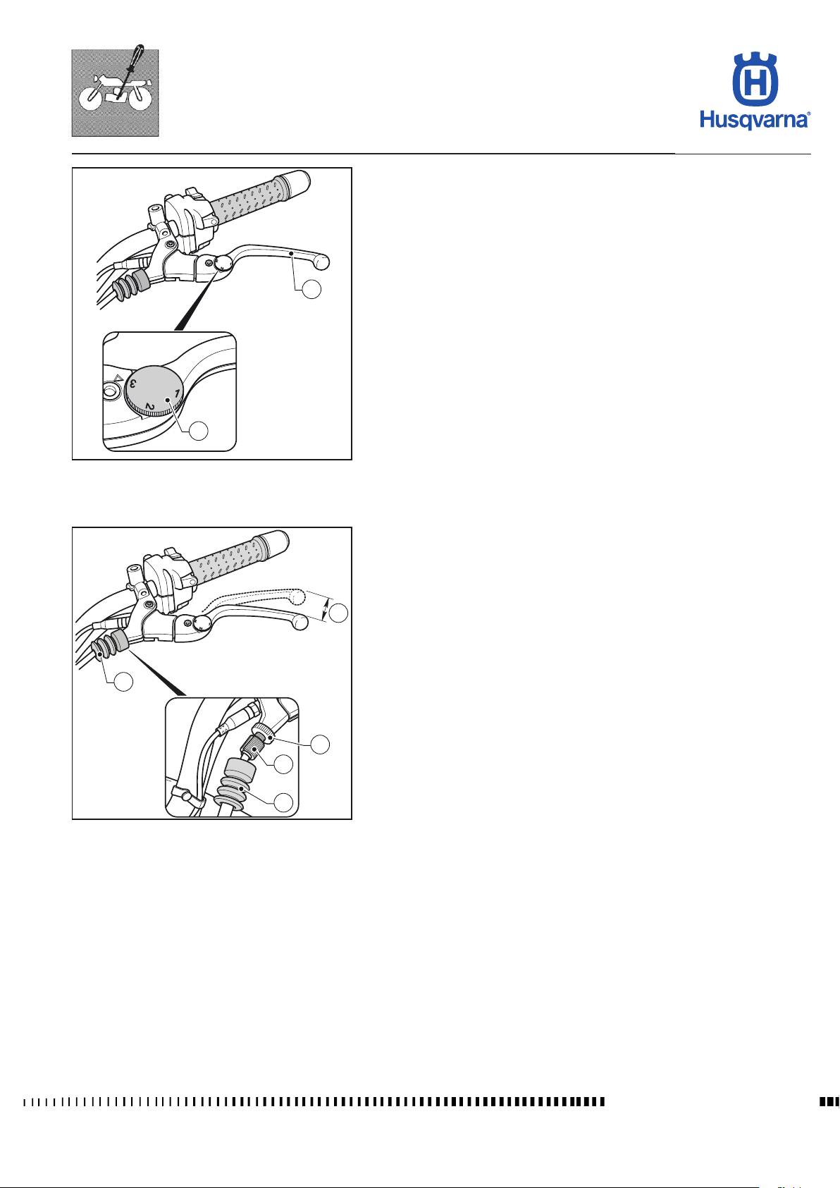
The lever (1) can be adjusted (3 settings available) to suit the rider's hand size
To regulate the position of the lever (1) push it outwards and then select the
required position by means of the adjuster screw (2).
1
2
H11673
Clutch free play adjustment
Free play (A) must be 5 -10 mm (0.196 - 0.39 in).
- Move the rubber gaiter (1);
- regulate the adjuster screws (2) and the counter adjuster screw (3) to obtain
A
the indicated free play.
- after completing the operation, make sure the counter adjuster screw (3) is
properly tightened and then replace the rubber gaiter (1).
1
3
2
1
H11674
D.7
Workshop Manual Ed. 09-2012
Page 38
SETTINGS AND ADJUSTMENTS
TR 650 TERRA 2013 - TR 650 STRADA 2013
Rear brake pedal free play adjustment
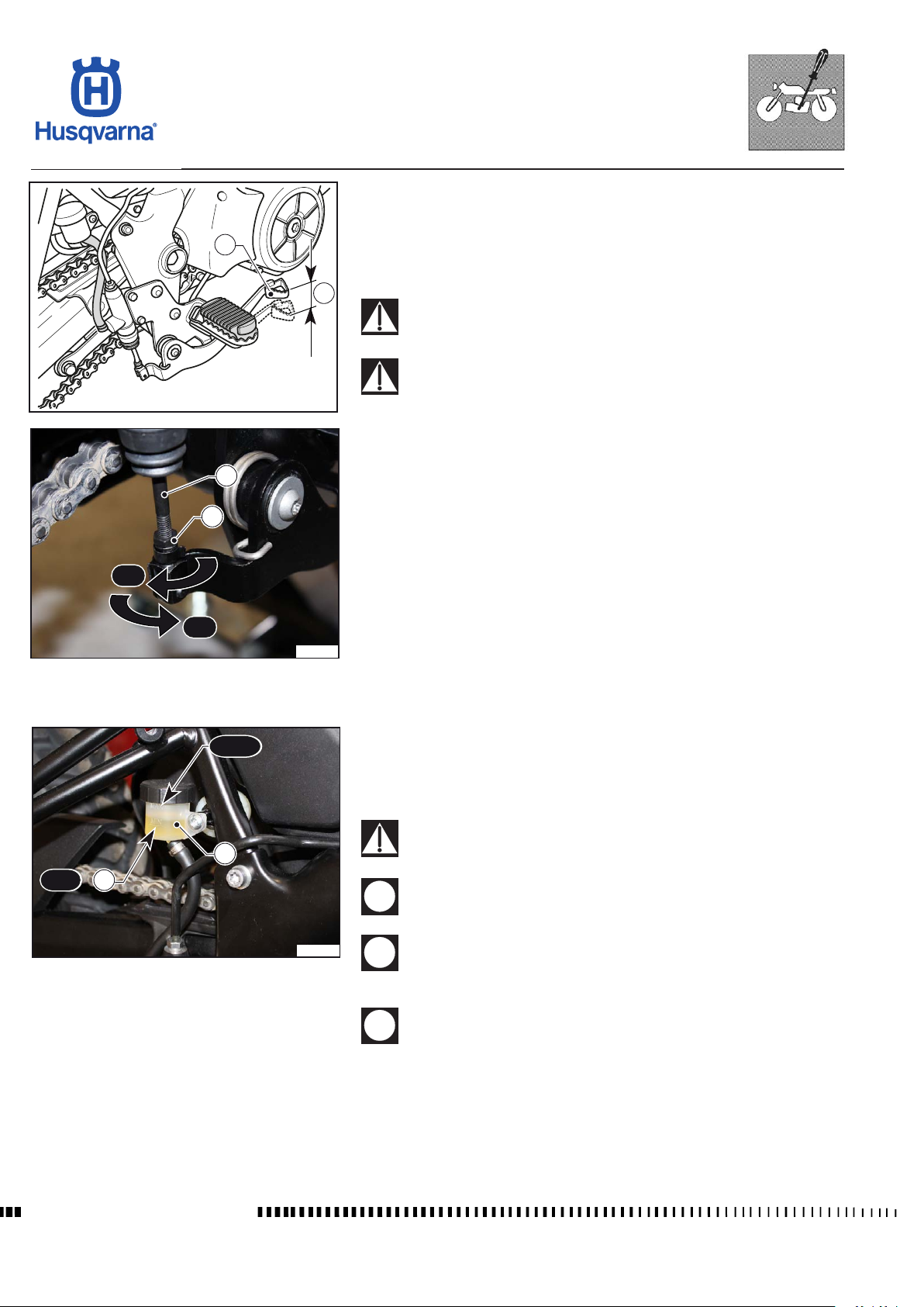
Before staring the braking action, rear brake pedal (1) shall have a free play
(B) of 5-10 mm (0,196 ÷ 0,39 in.). Should this not happen, operate as follows:
1
H11675
3
2
- Loosen the nut (2);
- Operate the master cylinder linkage (3) to increase or decrease free play;
- Tighten the nut (2) at the end of the operation.
B
When the free play requirement is not met, the brake pads will be
subjected to an early wear that may lead to TOTAL BRAKE INEFFECTIVENESS.
If the brake pedal feels mushy when pulled, there may be air in the
brake line or the brake may be defective. CHECK THE BRAKING
SYSTEM (see Section L).
C: to increase clearance
D: to decrease clearance
MIN
D
C
H11676
Rear brake uid level check
MAX
2
The uid level in the master cylinder tank shall never be below the minimum
level (1) shown on the transparent reservoir (2).
A decrease in the uid level will let air into the system and increase the lever
stroke.
If the brake pedal feels mushy when pulled, there may be air in the
brake lines or the brake may be defective.
1
Do not spill brake uid onto any painted surface or light lens.
H11677
Do not mix two brands of uid. Completely change the brake uid
in the brake system if you wish to switch to another uid brand.
Workshop Manual Ed. 09-2012
Brake uid may cause irritation. Avoid contact with skin or eyes.
In case of contact, ush thoroughly with water and call a doctor if
your eyes were exposed.
D.8
Page 39
MAX
MIN
MAX
MIN
SETTINGS AND ADJUSTMENTS
TR 650 TERRA 2013 - TR 650 STRADA 2013
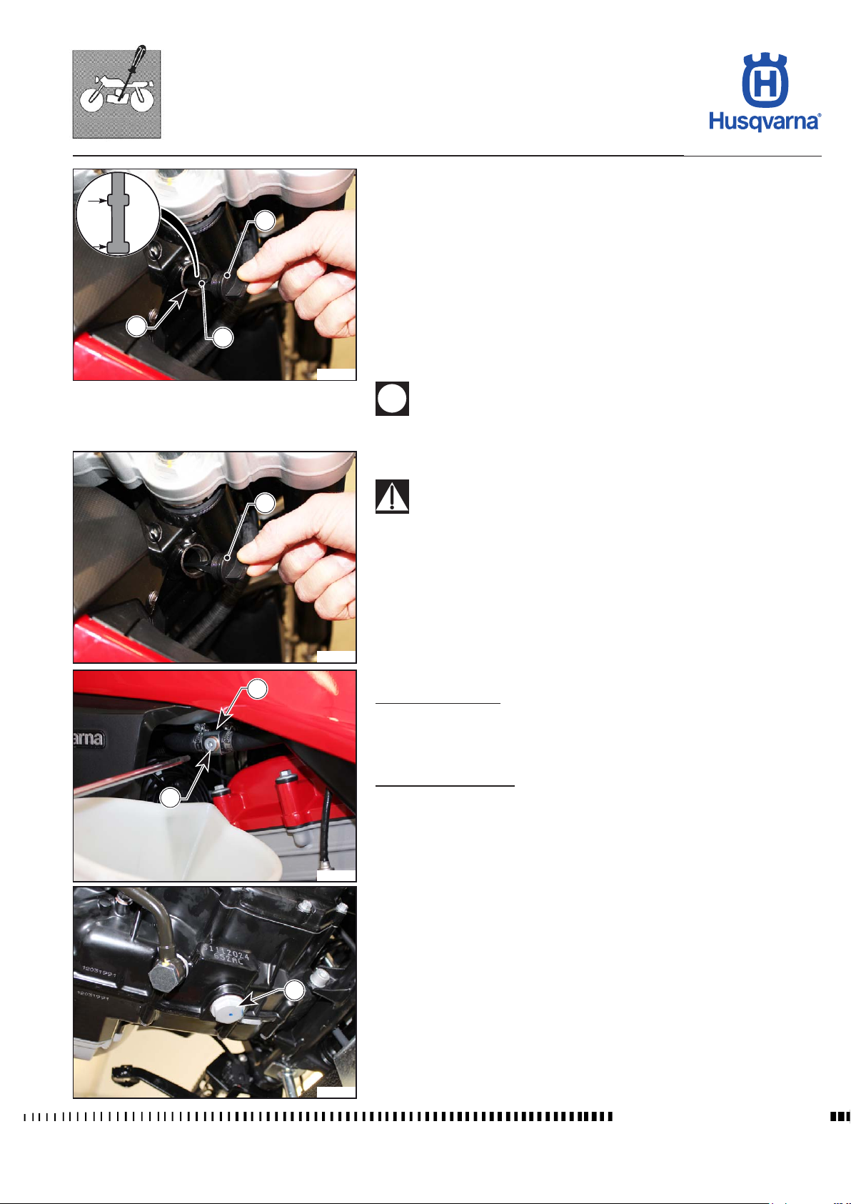
Oil level check
The oil level must be checked with the vehicle in vertical position on a flat surface.
1
3
2
H11678
1
- Start the motorcycle and heat the engine until the cooling fan starts; wait for
another 3 minutes and switch off the engine.
- Check the level as follows:
- Undo the cap (1) with the dipstick (2) and remove it from the frame.
- Clean the dipstick (2) with a cloth.
- Place the dipstick (2) in the hole (3) without screwing the cap on.
- Remove the dipstick (2) from the hole (3) and check that the level is be-
tween the two MIN and MAX marks.
- To top up, pour oil into the hole (3); for the type of oil, see the section
“Technical data”.
Never exceed max. level.
Engine oil replacement and cartridge lter replacement
Be careful not to touch hot engine oil.
Drain the oil with WARM ENGINE; proceed as follows:
- Place the motorcycle on its side stand
- Remove the cap (1) with the dipstick
Oil change must be performed in two stages:
Draining oil from tank;
Draining oil from engine
H11679
2
3
H11680
Draining oil from tank:
- Place a 2 litre container under the coupling (2) and then unscrew the screw
(3) and let the oil in the tank drain out completely.
- Once it has drained out, tighten the screw (3) with its corresponding washer.
Draining oil from engine:
- Place a container to collect the oil under the engine.
- Unscrew the screw (4) and let all the oil in the engine drain out completely.
- Once it has drained out, clean the magnetic screw (4), replace the gasket
and ret it on the engine by tightening it to torque.
Fill with oil as described in the relevant paragraph.
4
H11681
Workshop Manual Ed. 09-2012
D.9
Page 40
SETTINGS AND ADJUSTMENTS
TR 650 TERRA 2013 - TR 650 STRADA 2013
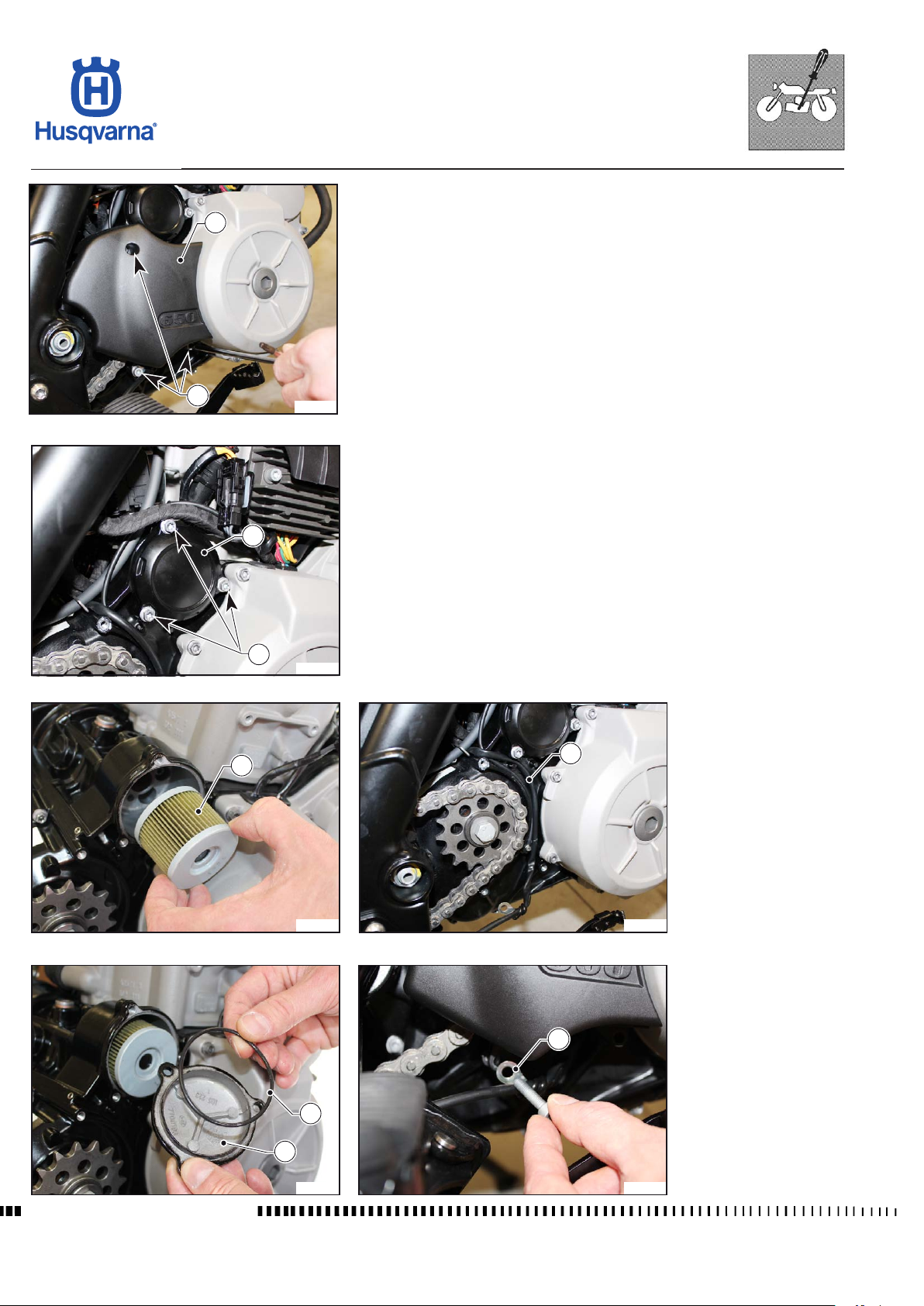
Replacement of cartridge lter
- Unscrew the screws (5) and remove the sprocket casing (6).
6
- Unscrew the screws (7) and remove the oil lter cover (8).
- Replace the lter (9) with a new one, then ret the cover (8) making sure that
the O-ring (10) is not damaged and positioned correctly on the cover.
- Ret the sprocket casing (6) making sure that the cable (11) of the rear stop
switch is positioned correctly as in the gure and that the cable guide (12) is
fastened externally onto the bottom screw.
5
H11682
8
7
H11683
9
11
Workshop Manual Ed. 09-2012
8
H11684
10
H11685
H11686
12
H11687
D.10
Page 41
SETTINGS AND ADJUSTMENTS
TR 650 TERRA 2013 - TR 650 STRADA 2013
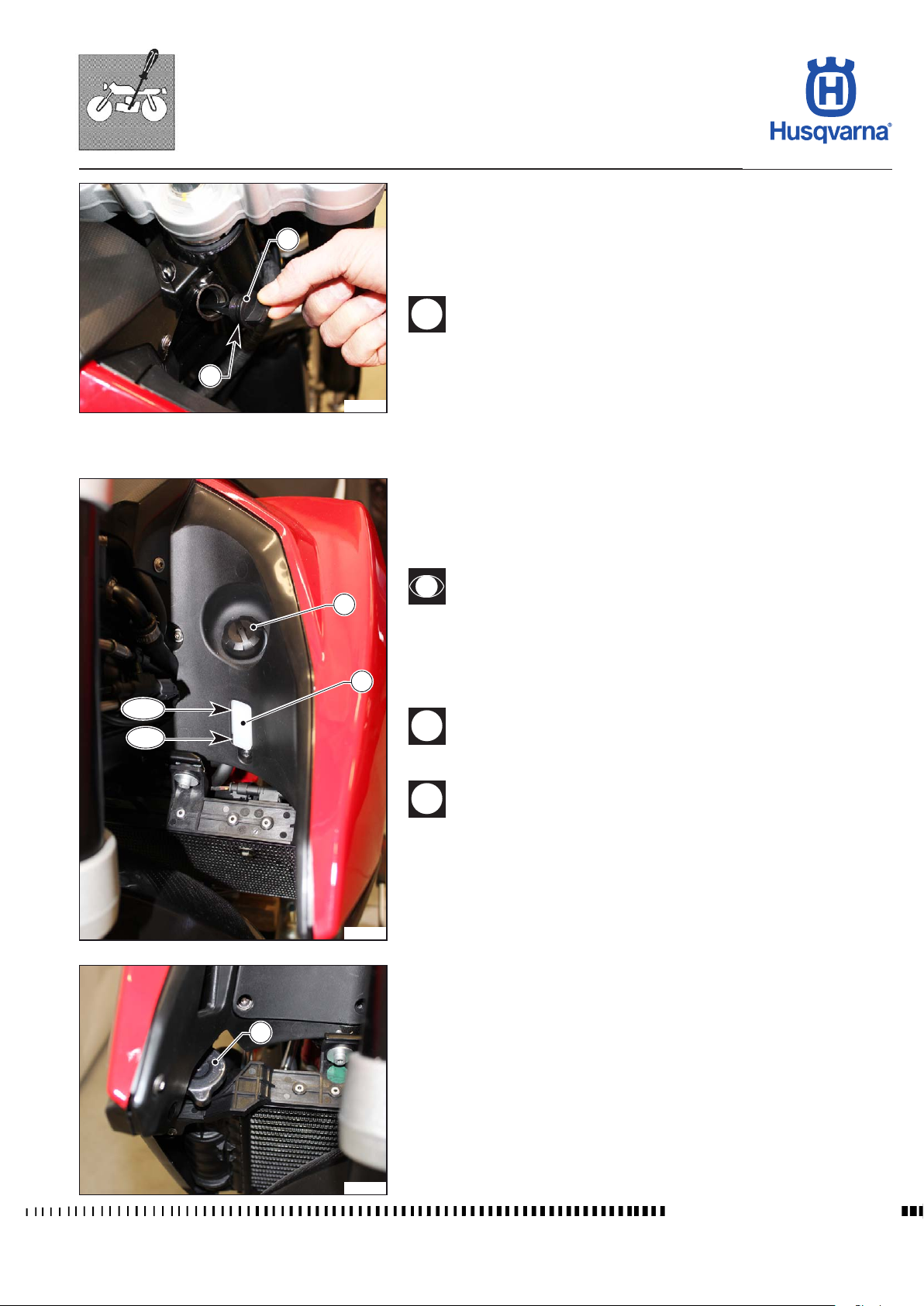
Filling
- Remove the cap (1) with the dipstick.
- Pour 1.5 litres of oil into the chassis tank.
1
2
H11743
- Run the engine for 30 seconds and then switch it off.
- Pour another 0.5 litres of oil into the chassis tank.
- Check the oil level as described in the relevant paragraph.
Check the condition of the gasket (2) of the cap (1) with the dipstick
and if it is damaged, replace it.
For the type of oil to use, refer to the “Technical data”paragraph.
Coolant level check
When the engine is cold, check that the level of the coolant is between the MIN
and MAX marks on the expansion tank (1) on the left-hand side of the motorcycle.
If topping up is necessary, do the following:
MAX
MIN
3
1
H11689
Do not remove the radiator cap (2) since all the liquid in the expan-
sion tank (1) will ow out.
- Remove the cap (3) and add the uid needed to restore the level to the ex-
pansion tank (1).
(for the type of liquid to use, see the section “Technical data”).
Difculties may arise in eliminating coolant from painted surfaces.
If this occurs, wash off with water.
Never exceed max. level.
2
H11690
Workshop Manual Ed. 09-2012
D.11
Page 42
SETTINGS AND ADJUSTMENTS
TR 650 TERRA 2013 - TR 650 STRADA 2013
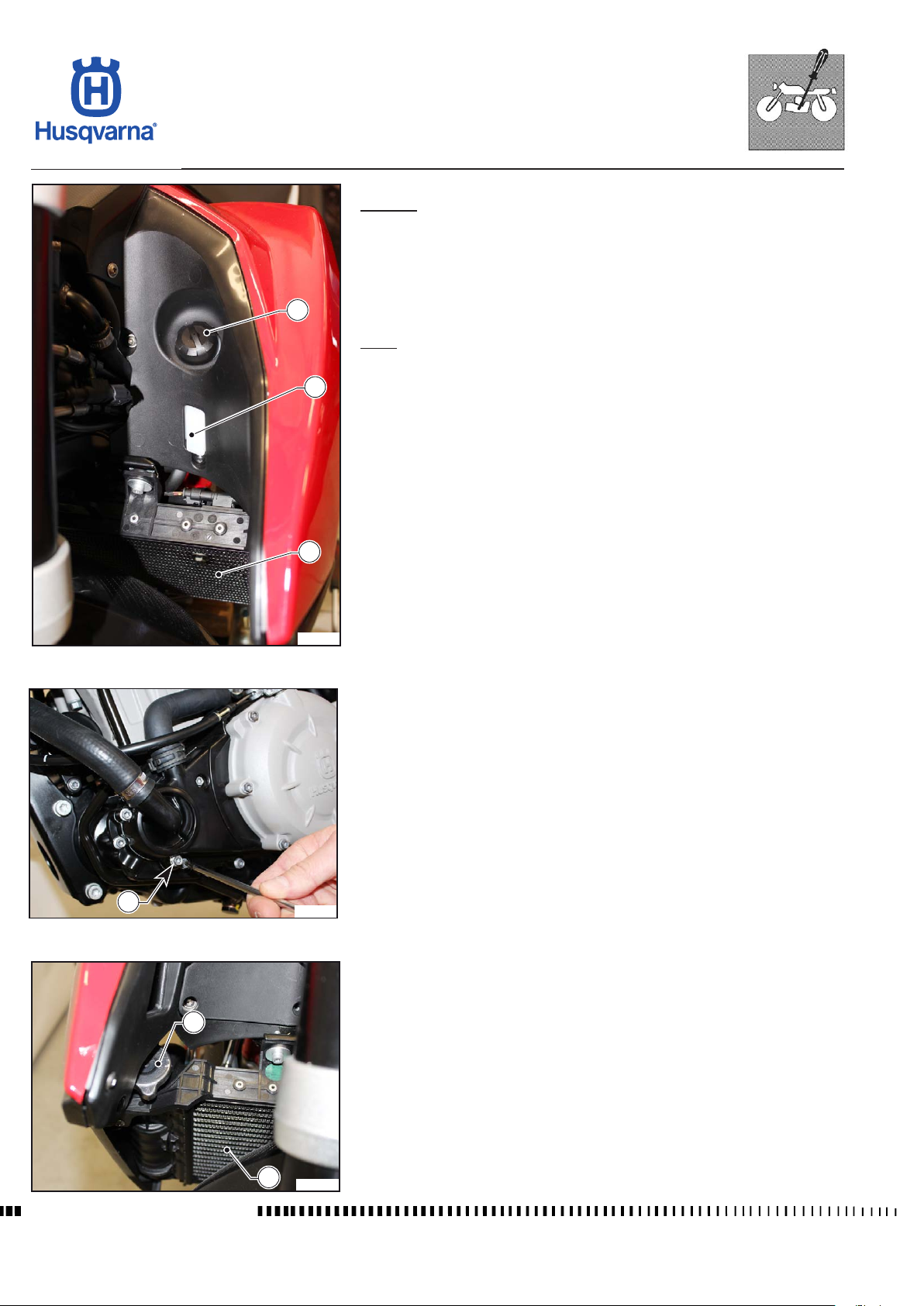
Coolant replacement
Drainage
- Place the motorcycle on its side stand.
- Remove the cap (1) of the expansion tank (2).
- Place a 2 litre container under the water pump and unscrew the screw (3).
- Let a small amount of coolant drain out and then turn the radiator cap (4) to
the rst click and wait for all the coolant to ow out of the water pump drain-
1
2
age hole.
Filling
- Re-tighten screw (2) on the water pump.
- Remove the radiator cap (4).
- Pour the coolant into the radiator (5) until it is full and gradually top up as the
level drops until it stays at maximum level.
- Put the radiator cap on again and pour the coolant into the expansion tank
(2) until it reaches maximum level.
- Put the cap (1) of the expansion tank on again.
- Start the engine, wait for the radiator cooling fan to start up and then wait
another 3 minutes.
- Switch off the engine and wait for it to cool, then check the level as described
in the relevant paragraph.
5
H11691
3
H11692
4
Workshop Manual Ed. 09-2012
5
H11693
D.12
Page 43
SETTINGS AND ADJUSTMENTS
TR 650 TERRA 2013 - TR 650 STRADA 2013
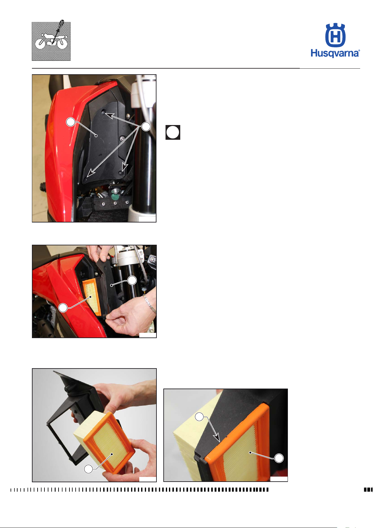
Air lter check
Note: Clean the lter area before removing the cover.
- Unscrew the screws (1) and remove the cover (2) together with the lter (3);
- remove the lter (3) and check that it is not clogged/dirty; replace if neces-
sary;
- when retting, check that the lter (3) is correctly placed in its housing (4).
2
1
Before retting the lter, check that the contact surfaces between
the lter, the lter box and the cover are completely clean.
H11694
2
3
H11695
4
3
3
H11696
D.13
H11697
Workshop Manual Ed. 09-2012
Page 44
SETTINGS AND ADJUSTMENTS
TR 650 TERRA 2013 - TR 650 STRADA 2013
1
A
2
H11744
6
4
Chain tension adjustment
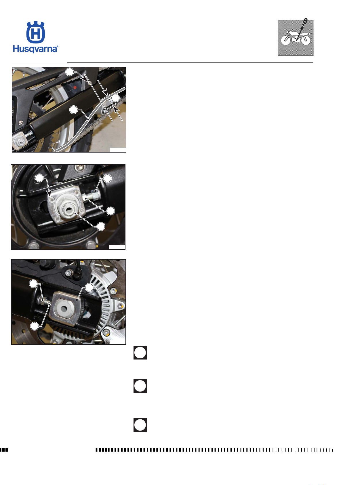
Chain should be checked, adjusted and lubricated as per the Maintenance
Chart to ensure safety and prevent excessive wear.
If the chain becomes badly worn or is adjusted incorrectly (i.e., it is too loose or
too tight), it could jump out of the sprocket or break.
- Position the motorcycle on the side stand so the chain is not stressed and
loaded;
- where the screw (1) is located, lift the chain (2) upwards and measure the
chain travel.
- the correct setting must be 45 mm (1.77 in).
If this is not the case, proceed as follows:
- make sure that the motorcycle is fully upright on the special rear support
stand (optional).
- on the right side, loosen the locking nut (3) of the wheel axle;
- loosen the check nuts (4) on both chain tensioners;
- turn the adjuster screws (5) to obtain the correct tension and check on both
sides that the wheel centring sliders (6) are in the same position as the markings in the chain tensioner slider seats on the swinging arms;
- once adjusted, tighten the check nuts (4) and the wheel axle nut (3).
After adjusting, always check that distance "A" is 45 mm (1.77 in).
5
3
H11699
4
5
6
Lubricating the chain
Lubricate the chain following these instructions.
H11700
Never use grease to lubricate the chain. Grease helps to accumulate
dust and mud, which act as abrasive and help to rapidly wear out
the chain, the front and rear sprockets.
Do not wash the chain with high-pressure water jets and do not use
harsh or highly ammable solvents.
- After washing the chain using special detergent, dry it and lubricate with suitable spray grease.
Workshop Manual Ed. 09-2012
The chain lubricant must NOT come into contact with the tyres or
the rear brake disc.
D.14
Page 45
SETTINGS AND ADJUSTMENTS
TR 650 TERRA 2013 - TR 650 STRADA 2013
Suspension
The vehicle leaves the factory with standard settings for the front and rear suspension that meet most requirements.
Before making any change and afterwards, if the adjustment is not
satisfactory, always start from the standard suspension setting
and increase or decrease the adjusting clicks, one at a time.
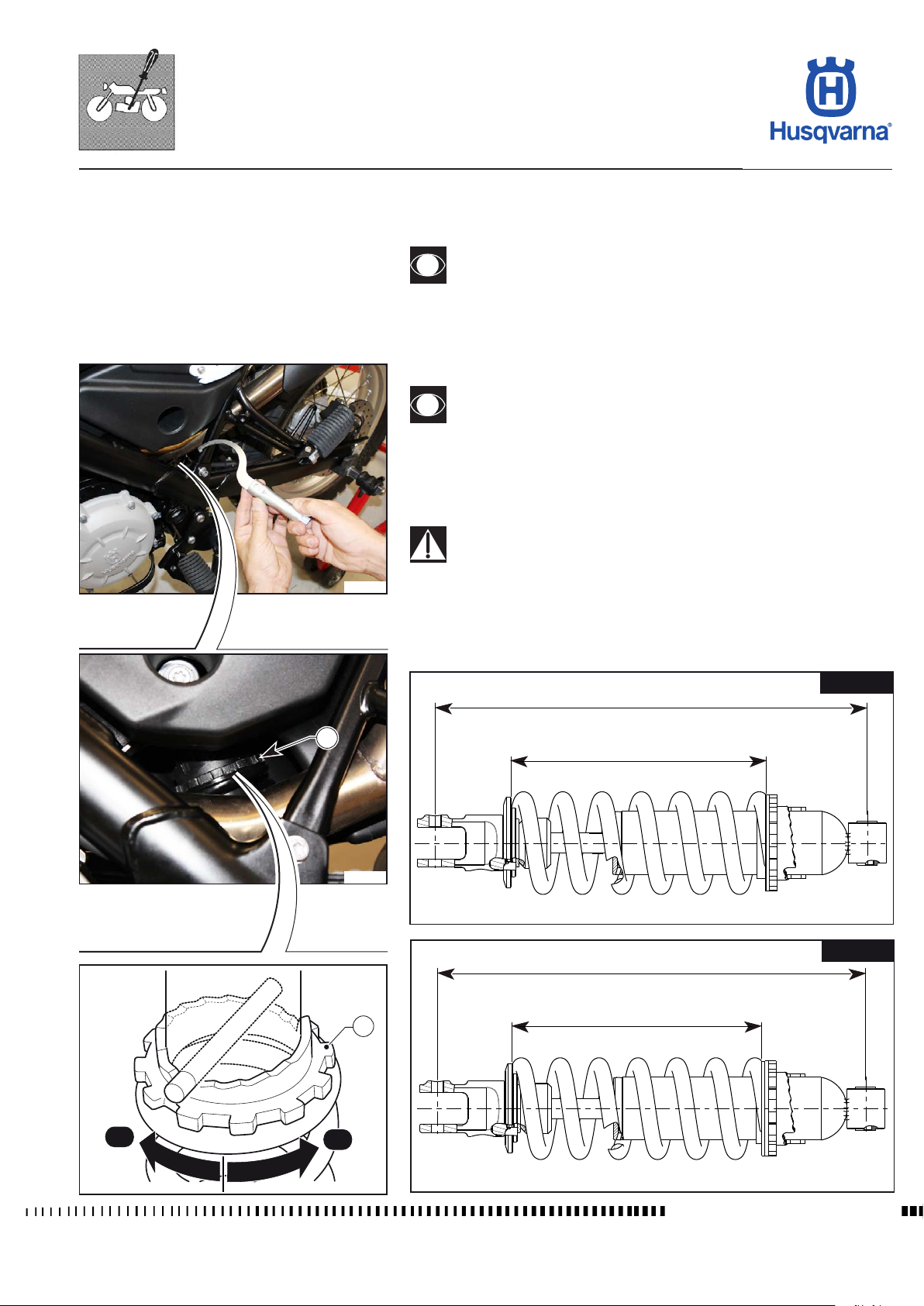
Shock absorber spring preload adjustment
This is easier to do if you lift the motorcycle at the centre so that
the rear wheel is released.
- Adjust the ring nut (1) using the spanner provided; by turning left “A”, the
preload increases;
by turning right “B” the preload decreases.
1
H11701
H11702
Be careful not to touch hot exhaust pipe while adjusting the shock
absorber.
A: Wheelbase
B: Spring in its seat
A= 341 ± 1,5 mm (13,4252 ± 0,0591 in.)
B= 201 ± 1,5 mm (7,9134 ± 0,0591 in.)
A= 341 ± 1,5 mm (13,4252 ± 0,0591 in.)
TERRA
H11704
STRADA
1
B= 198 ± 1,5 mm (7,7953 ± 0,0591 in.)
A
B
H11703
H11705
Workshop Manual Ed. 09-2012
D.15
Page 46
SETTINGS AND ADJUSTMENTS
TR 650 TERRA 2013 - TR 650 STRADA 2013
Rebound shock absorber hydraulic damping adjustment
It is possible to adjust the rebound travel of the shock absorber.
B) REBOUND - Standard setting:
- 11 clicks
1
H11706
(adjuster 1)
To reset the standard setting, turn lower adjuster (1) clockwise until reaching fully
closed position. Then turn it back the number of clicks specied above.
In order to obtain a smooth braking action, turn the adjuster counter clockwise.
Vice versa to obtain a harder braking action.
Fork adjustment
On the fork installed on this motorbike version, it is not possible to perform any
type of adjustment.
1
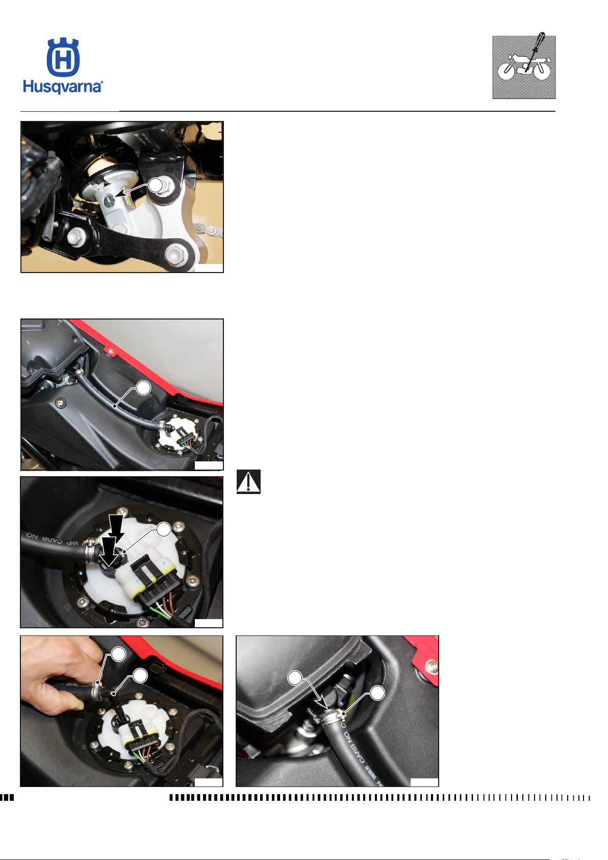
Fuel supply hose inspection and replacement
- Remove the saddle as described in the relevant paragraph.
- Check fuel supply hose (1) conditions; if cracked, swollen, kinked, etc. it is
necessary to change it as follows:
- Press the ring nut (2) and unfasten the union (3).
- Open the clamps (4) and detach the pipe (1) from the unions (3) and (5).
H11707
During this operation, make sure that you do not damage the hose
holder coupling on the throttle body.
- Replace the pipe (1) and close the clamps (4) on unions (5) and (3).
2
H11708
- Ret the union (3) by pressing it down.
4
3
5
4
Workshop Manual Ed. 09-2012
H11709
H11710
D.16
Page 47
SETTINGS AND ADJUSTMENTS
TR 650 TERRA 2013 - TR 650 STRADA 2013
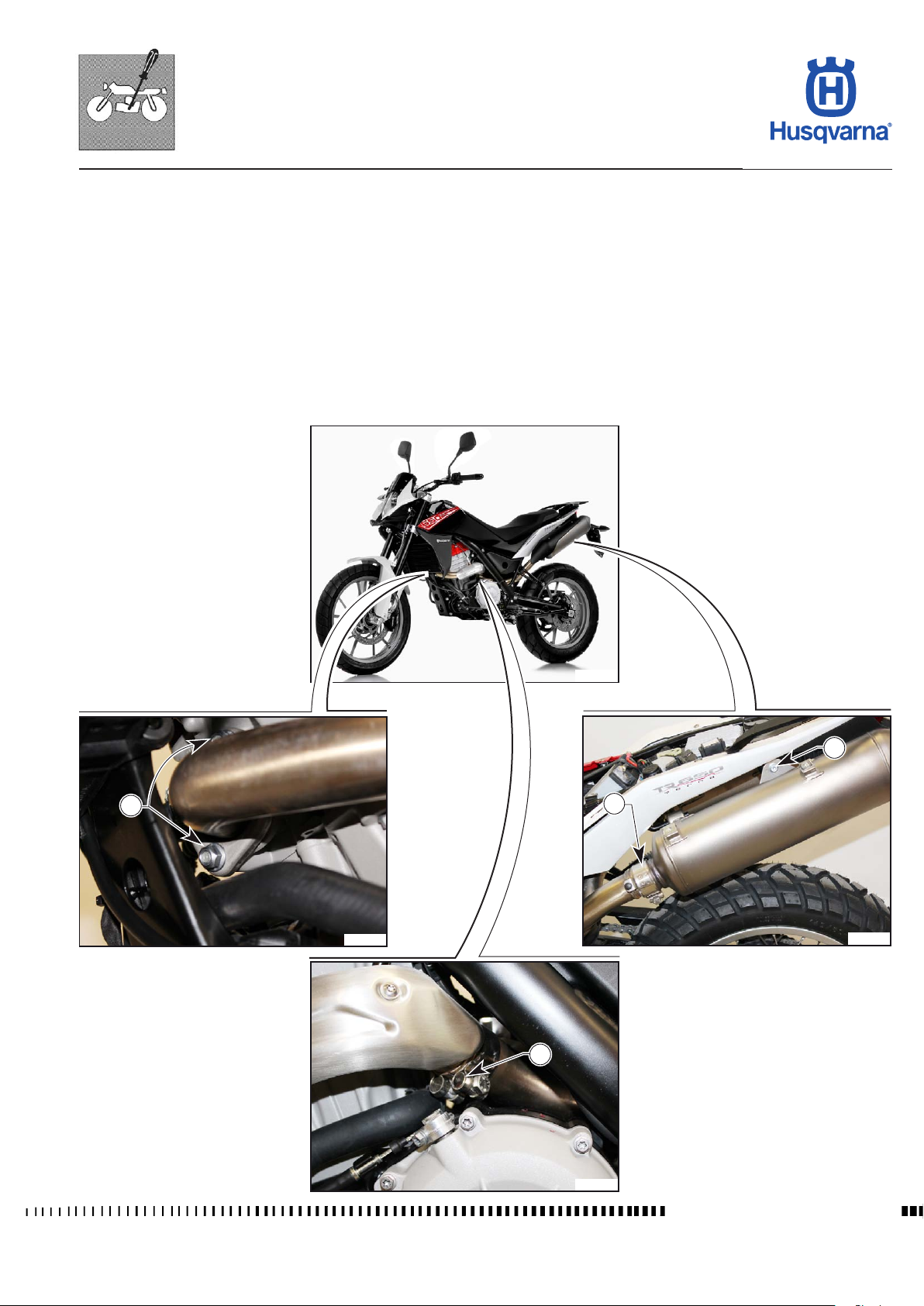
Exhaust system check
Perform a visual inspection of the exhaust system rst, in order to identify possible gas leaks from the sealing elements (gaskets), and to ensure that the
Silent-Blocks are not damaged.
Subsequently, inspect the single components by disassembling the exhaust
system.
Also check the tightening of the ange nuts (1) fastening the manifold to the
cylinder head and the clamps (2) fastening the silencers to the manifolds as well
as the tightening of the screw (3) fastening the silencer to its support.
The damaged or broken parts must be replaced.
H11711
3
1
H11712
2
H11714
2
D.17
H11713
Workshop Manual Ed. 09-2012
Page 48
SETTINGS AND ADJUSTMENTS
TR 650 TERRA 2013 - TR 650 STRADA 2013
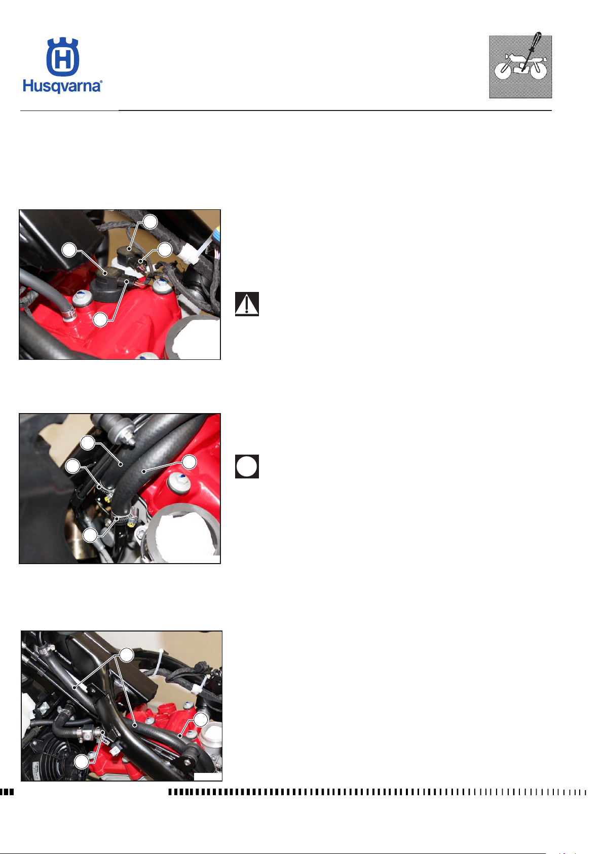
Idle speed adjustment
The idle speed is pre-set by the control unit (1550 rev/min.) and the stepper
motor ensures that this value is preserved.
No manual adjustment is possible, nor any adjustment through the diagnostic
tool.
Checking and adjustment of valve clearance
4
3
2
1
Remove the lter box and the throttle body as described in the relevant paragraphs.
Drain the oil from the tank on the chassis as described in the relevant paragraph.
- Disconnect the connectors (1) and (2) from the coils/tubes (3) and (4).
- Remove the coils/tubes (3) and (4).
- Remove the spark plugs.
When retting, do not invert the coils / tubes; the coil with the white
ring nut should be tted on the outer part of the cylinder head and
the connector with the white clamp connected to the cable.
H11715
- Loosen the clamps (5) and (6) and remove the two pipes (7) and (8). Place
them so that they do not drip oil.
7
5
8
When retting, do not invert the position of the two pipes;
Pipe 7 = oil return pipe to tank must go over the ABS pipes;
Pipe 8 = oil delivery pipe must go under the ABS pipes.
6
H11716
7
8
Workshop Manual Ed. 09-2012
8
H11717
D.18
Page 49
SETTINGS AND ADJUSTMENTS
TR 650 TERRA 2013 - TR 650 STRADA 2013
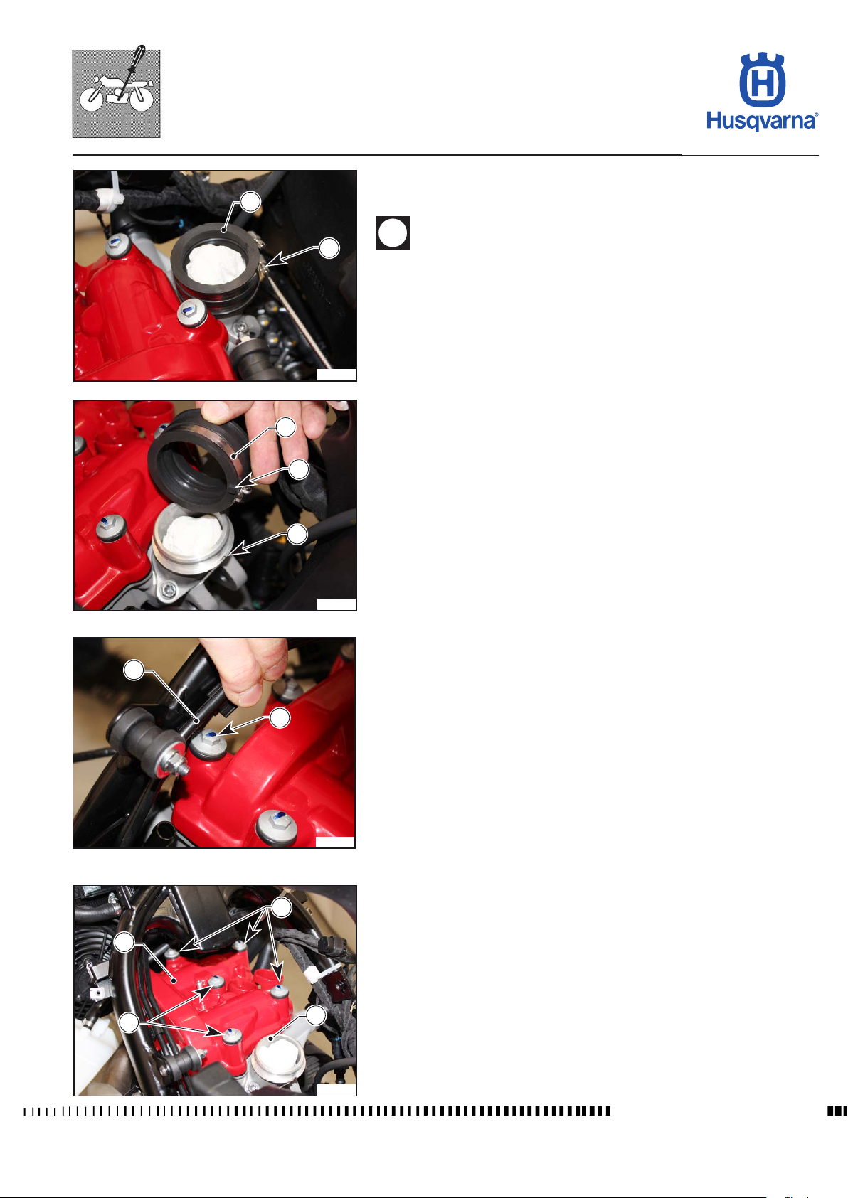
- Loosen the clamp (9) and remove the intake coupling (10) from the cylinder
head.
10
10
9
H11718
When retting the intake coupling (10) make sure you place the
prong (A) on the slot (B) of the intake manifold.
- Disconnect the cylinder head from the electrical system.
A
B
H11719
14
13
11
12
13
- Move the two pipes (11) of the ABS to unscrew the screw (12), then unscrew the screws (13) and remove them.
H11720
- Remove the head cover (14) at the back of the motorcycle; if this is difcult,
remove the intake manifold (15) by unscrewing the corresponding screws
without losing the corresponding gaskets.
- Adjust valve clearance as described in the relevant paragraph in Section F.
15
H11721
Workshop Manual Ed. 09-2012
D.19
Page 50

Page 51
GENERAL PROCEDURES
TR 650 TERRA 2013 - TR 650 STRADA 2013
Section
E
E.1
Workshop Manual Ed. 09-2012
Page 52
GENERAL PROCEDURES
TR 650 TERRA 2013 - TR 650 STRADA 2013
Sommario
Stand removal / replacement........................................................................E.3
Saddle removal.............................................................................................E.4
Removal of central upper cover....................................................................E.4
Side panel removal .......................................................................................E.5
Removal of luggage rack ..............................................................................E.5
Removal of tail cover ....................................................................................E.6
Removal of rear panels ................................................................................E.6
Removal of antitheft device compartment cover ..........................................E.7
Replacement of the saddle lock key lock ....................................................E.8
Removal of saddle lock ................................................................................E.9
Removal of number plate holder ..................................................................E.9
Removal of tail light ....................................................................................E.12
Removal of rear turning indicators..............................................................E.12
Removal of radiator guards ........................................................................E.13
Removal of lower tail cover ........................................................................E.14
Removal of tail chassis ...............................................................................E.16
Front fairing removal...................................................................................E.17
Front turning indicator removal ...................................................................E.18
Combined dashboard removal ...................................................................E.19
Removal of front mudguard ........................................................................E.20
Removal of fuel tank ...................................................................................E.21
Fuel pump removal .....................................................................................E.24
Fuel pump inspection .................................................................................E.26
Removal of lter box ...................................................................................E.27
Dismantling of lter box ..............................................................................E.29
Throttle body removal .................................................................................E.30
Exhaust system removal ............................................................................E.31
Exhaust system removal ............................................................................E.32
Lambda sensor removal .............................................................................E.34
Coil / Stick-Coil removal and spark plug test ..............................................E.34
Horn removal ..............................................................................................E.35
Radiator removal ........................................................................................E.35
Removal of electric fan ...............................................................................E.37
Gearbox lever removal ...............................................................................E.38
Removal of engine......................................................................................E.39
Reassembly of engine ................................................................................E.42
Workshop Manual Ed. 09-2012
E.2
Page 53
GENERAL PROCEDURES
TR 650 TERRA 2013 - TR 650 STRADA 2013
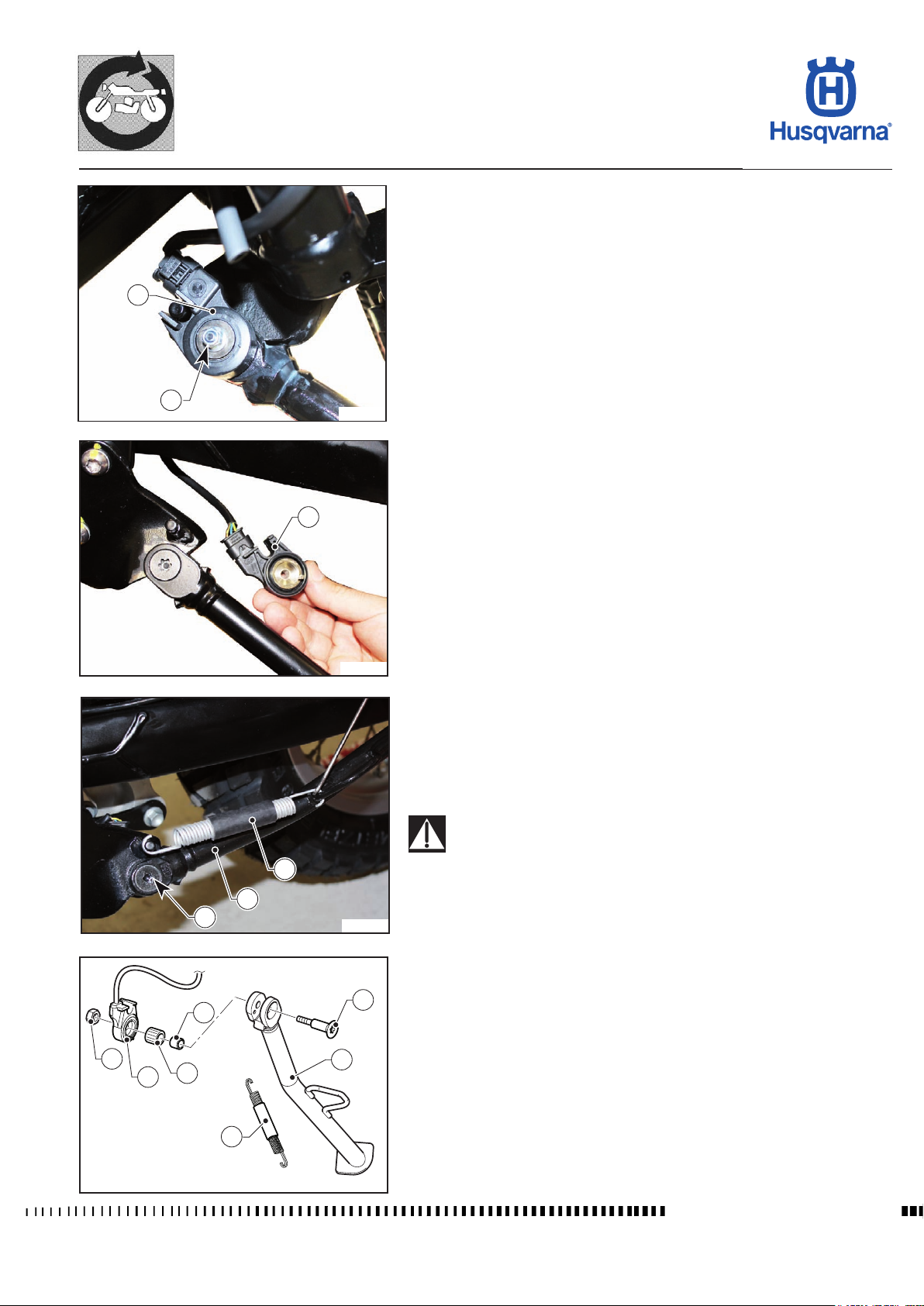
Stand removal / replacement
- Loosen the nut (1) and remove the rotary type switch (2).
2
1
H11790
2
H11791
- Release the spring (3).
- Loosen the screw (4) and remove the stand (5).
- When reassembling, grease the screw (4) and the stand fork and ret the
bushing (6) correctly with its bearing (7).
The screw (4) must be replaced at every disassembly.
3
NOTE: For the correct installation of the rotatory type switch (2), refer to
chapter "M".
5
4
H11792
4
6
1
7
2
5
3
H11793
Workshop Manual Ed. 09-2012
E.3
Page 54
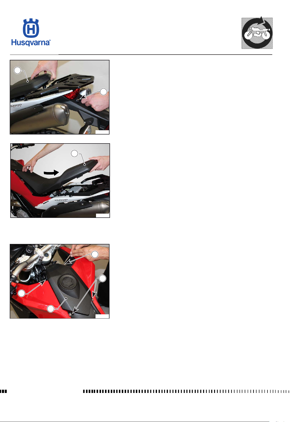
GENERAL PROCEDURES
TR 650 TERRA 2013 - TR 650 STRADA 2013
Saddle removal
2
H11660
2
To remove the saddle proceed as follows:
- Insert the key in the lock (1) positioned in the rear part of the motorcycle;
- turn the key clockwise to release the saddle (2), and then lift it and pull it out
towards the rear, releasing it from the front fastener.
To t the saddle back on, fasten it at the front and then press the rear until the
1
fastening "Click" is heard.
H11661
1
Removal of central upper cover
- Unscrew the four screws (1) that fasten the cover (2) and remove it.
1
1
2
H11662
Workshop Manual Ed. 09-2012
E.4
Page 55
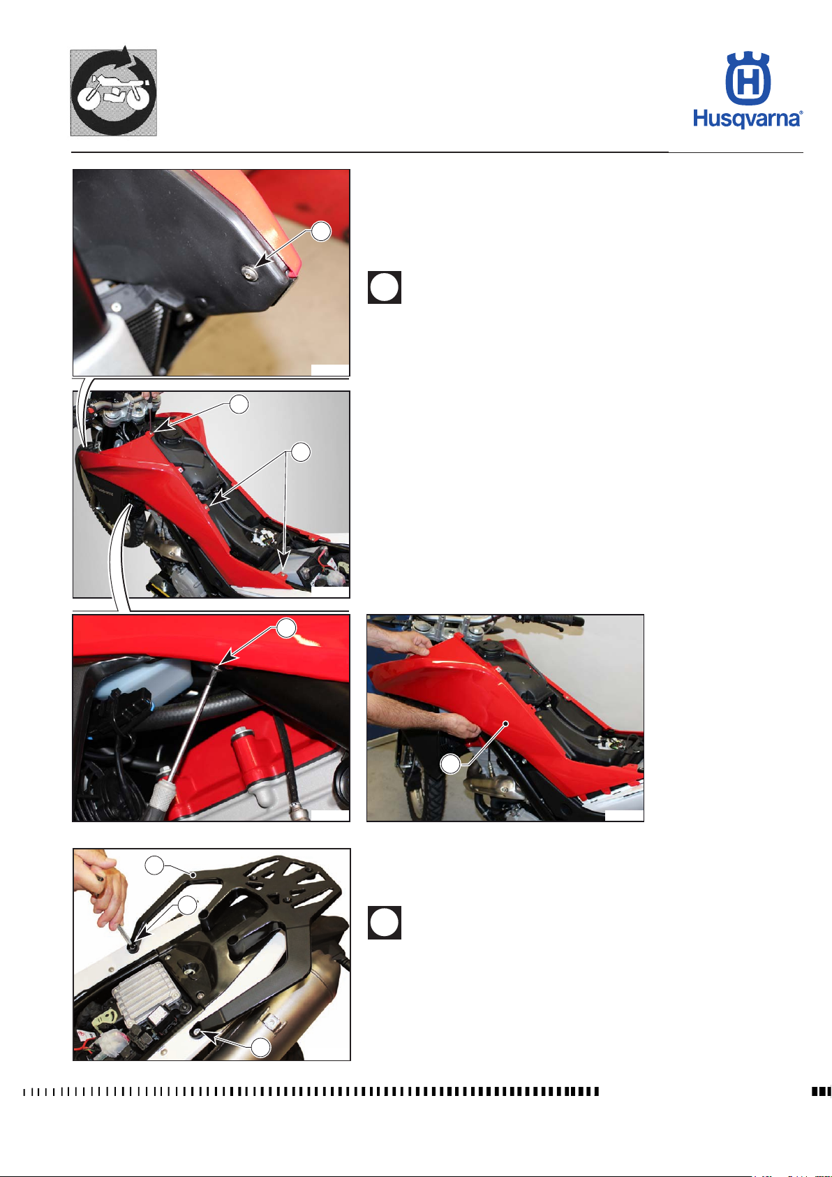
GENERAL PROCEDURES
TR 650 TERRA 2013 - TR 650 STRADA 2013
Side panel removal
- Remove the saddle as described in the relevant paragraph.
- Remove the upper cover as described in the relevant paragraph.
- Unscrew the ve screws (1) and remove the left side panel (2) by releasing
1
H11664
1
1
the xing tabs.
- Repeat to remove the right side panel.
When reassembling, rst insert the rear xing tabs and then the
front ones.
H11663
1
2
H11665
2
Removal of luggage rack
Remove the saddle as described in the relevant paragraph.
- Unscrew the screws (1) and remove the luggage rack (2).
H11666
1
When reassembling, tighten the screws to torque by placing the
longest ones at the rear and the shortest ones at the front of the
luggage rack.
1
H11794
Workshop Manual Ed. 09-2012
E.5
Page 56
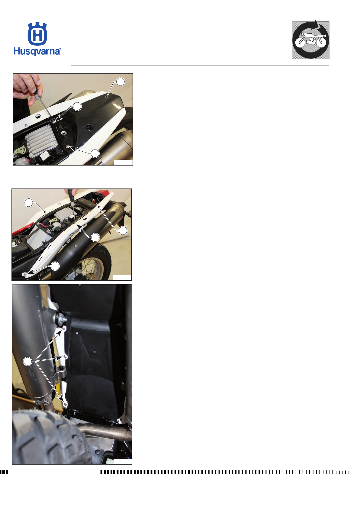
GENERAL PROCEDURES
TR 650 TERRA 2013 - TR 650 STRADA 2013
Removal of tail cover
2
1
1
H11795
4
3
1
Remove the saddle and luggage rack as described in the relevant paragraphs.
- Unscrew the screws (1) and remove the tail (2).
Removal of rear panels
Remove the saddle, luggage rack, rear tail cover and the side panels as described
in the relevant paragraphs.
- Unscrew the upper screws (1).
- Unscrew the three lower screws (2) and remove the left rear panel (3).
Repeat the above steps to remove the right rear panel (4).
1
H11796
2
Workshop Manual Ed. 09-2012
H11797
E.6
Page 57
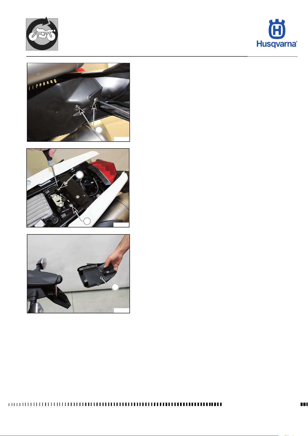
GENERAL PROCEDURES
TR 650 TERRA 2013 - TR 650 STRADA 2013
Removal of antitheft device compartment cover
Remove the saddle, the luggage rack and the rear tail cover as described in the
relevant paragraphs.
- Unscrew the two lower screws (1) and the two upper screws (2) and remove
the cover (3).
1
H11798
2
2
H11799
3
H11800
E.7
Workshop Manual Ed. 09-2012
Page 58
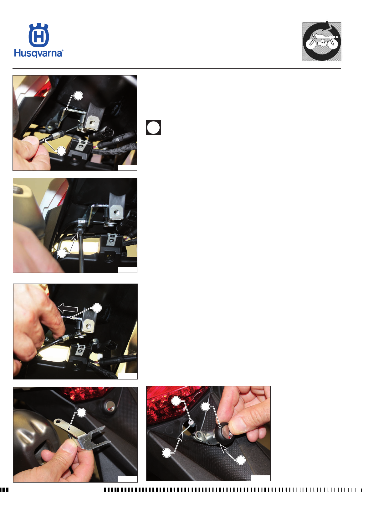
GENERAL PROCEDURES
TR 650 TERRA 2013 - TR 650 STRADA 2013
Replacement of the saddle lock key lock
Remove the saddle, the luggage rack, the rear tail cover and the antitheft device
2
1
H11801
compartment cover as described in the relevant paragraphs.
- Push up the end of the cable (1) and remove it from the support plate (2).
- Unscrew the screw (3) and remove the plate (2) from the plastic.
- Remove the key block (4) and detach it from the cable (5).
When retting the new key block, follow the same steps for removal
in reverse order and make sure that the reference guide (6) in the
block is correctly inserted into the seat (7) in the number plate
holder.
3
H11802
2
H11803
5
4
2
Workshop Manual Ed. 09-2012
H11804
7
6
H11805
E.8
Page 59
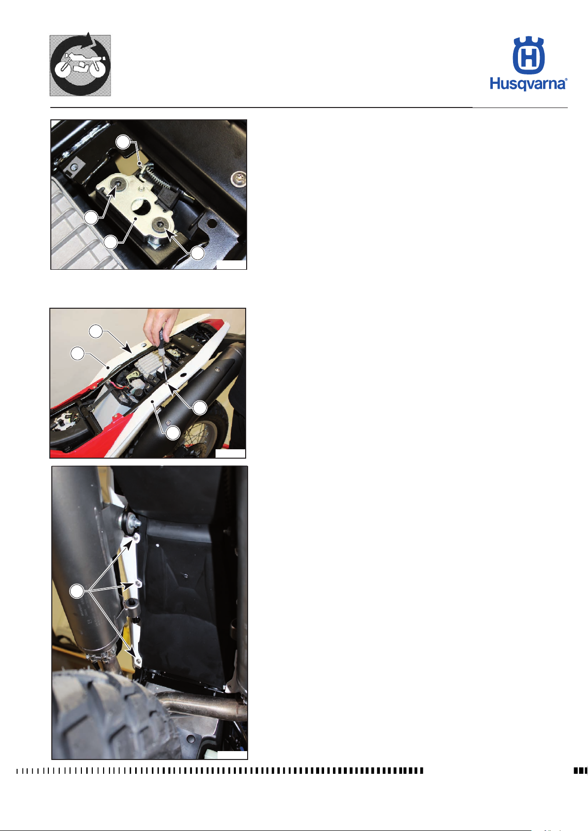
GENERAL PROCEDURES
TR 650 TERRA 2013 - TR 650 STRADA 2013
Removal of saddle lock
Remove the saddle, the luggage rack and the rear tail cover as described in the
2
1
3
1
H11806
1
3
relevant paragraphs.
Removal of number plate holder
Remove the saddle, the luggage rack, the rear tail cover and the antitheft device
compartment cover as described in the relevant paragraphs.
- Unscrew the upper screws (1) and the lower screws (2) of the rear panels
(3).
1
3
H11807
2
H11797
Workshop Manual Ed. 09-2012
E.9
Page 60
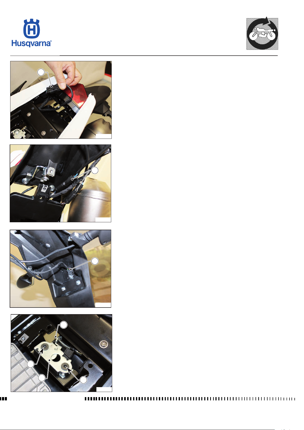
GENERAL PROCEDURES
TR 650 TERRA 2013 - TR 650 STRADA 2013
- Disconnect the tail light connector (4) and the turning indicator connectors
4
H11808
5
(5).
H11809
- Remove the licence plate light bulb holder (6).
6
H11810
9
- Unscrew the two screws (7) of the lock (8) and remove the cable (9).
7
8
Workshop Manual Ed. 09-2012
7
H11811
E.10
Page 61
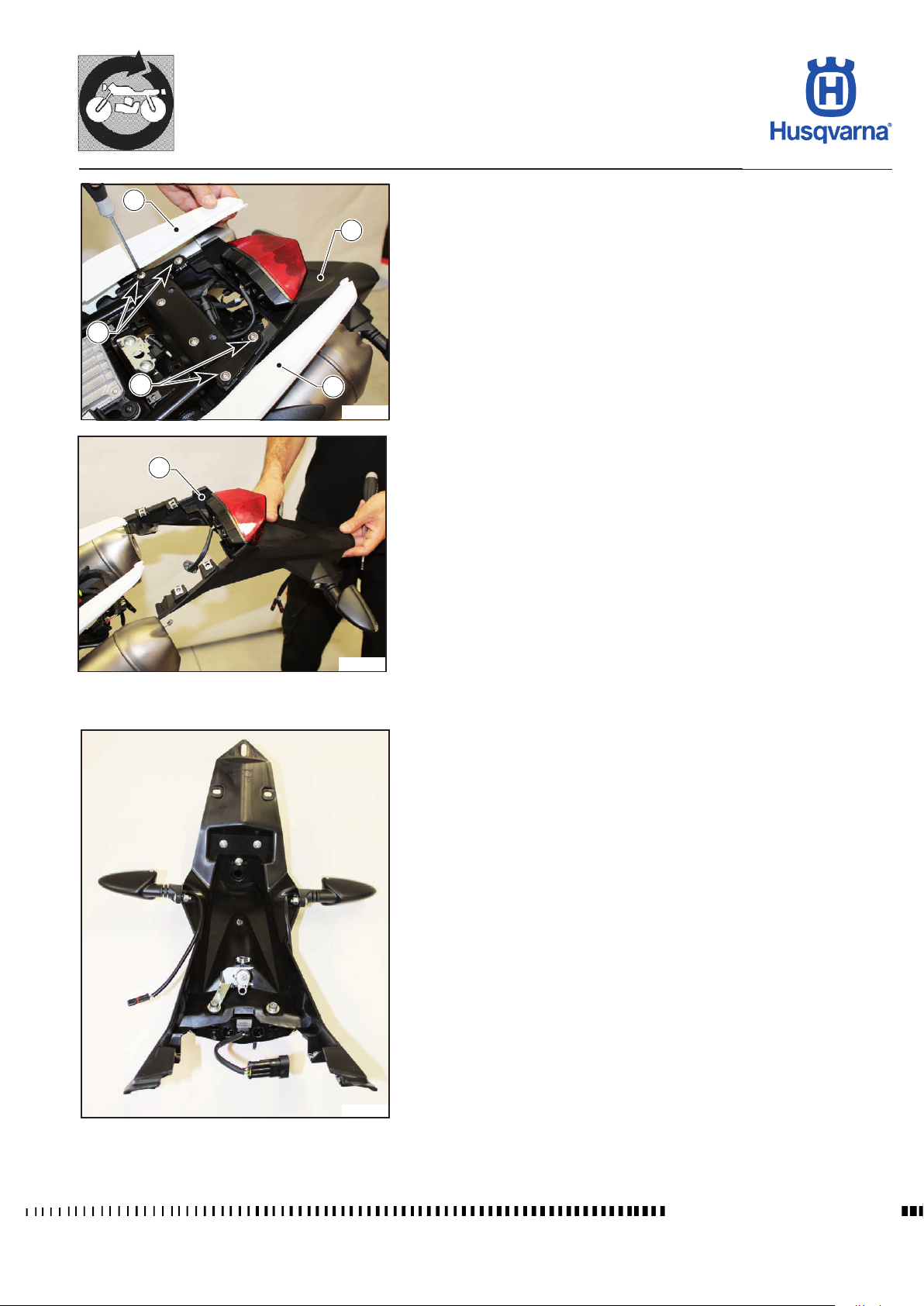
GENERAL PROCEDURES
TR 650 TERRA 2013 - TR 650 STRADA 2013
10
3
10
11
3
11
H11812
- Pull the two rear panels (3) apart so that you can access the screws (10).
- Unscrew the screws (10) of the number plate holder (11) and remove it along
with the key block, tail light and turning indicators.
H11813
H11814
- Remove the various parts by unscrewing the relevant screws.
E.11
Workshop Manual Ed. 09-2012
Page 62
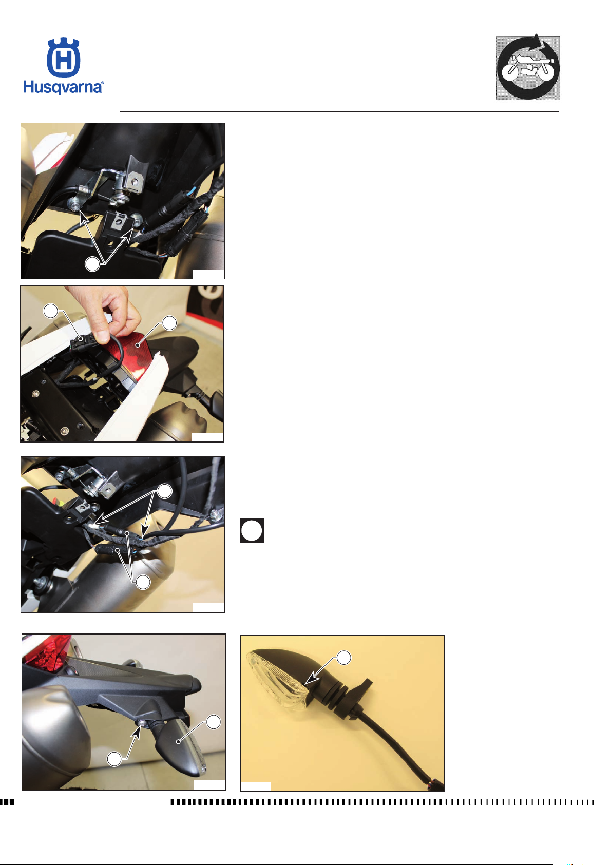
GENERAL PROCEDURES
TR 650 TERRA 2013 - TR 650 STRADA 2013
Removal of tail light
Remove the saddle, the luggage rack, the rear tail cover and the antitheft device
compartment cover as described in the relevant paragraphs.
- Unscrew the two screws (1), disconnect the connector (2) and remove the
tail light (3).
1
H11815
2
3
H11816
Removal of rear turning indicators
Remove the saddle, the luggage rack, the rear tail cover and the antitheft device
compartment cover as described in the relevant paragraphs.
DX
- Disconnect the two connectors (1).
- Unscrew the screws (2) and remove the turning indicators (3).
During the reassembly of the turning indicators, make sure that the
water discharge hole (4) faces downwards and that the connector
of the right-hand turning indicator is connected to the connector
marked with a white adhesive tape of the bike harness.
1
2
Workshop Manual Ed. 09-2012
H11817
3
H11818
4
H11819
E.12
Page 63
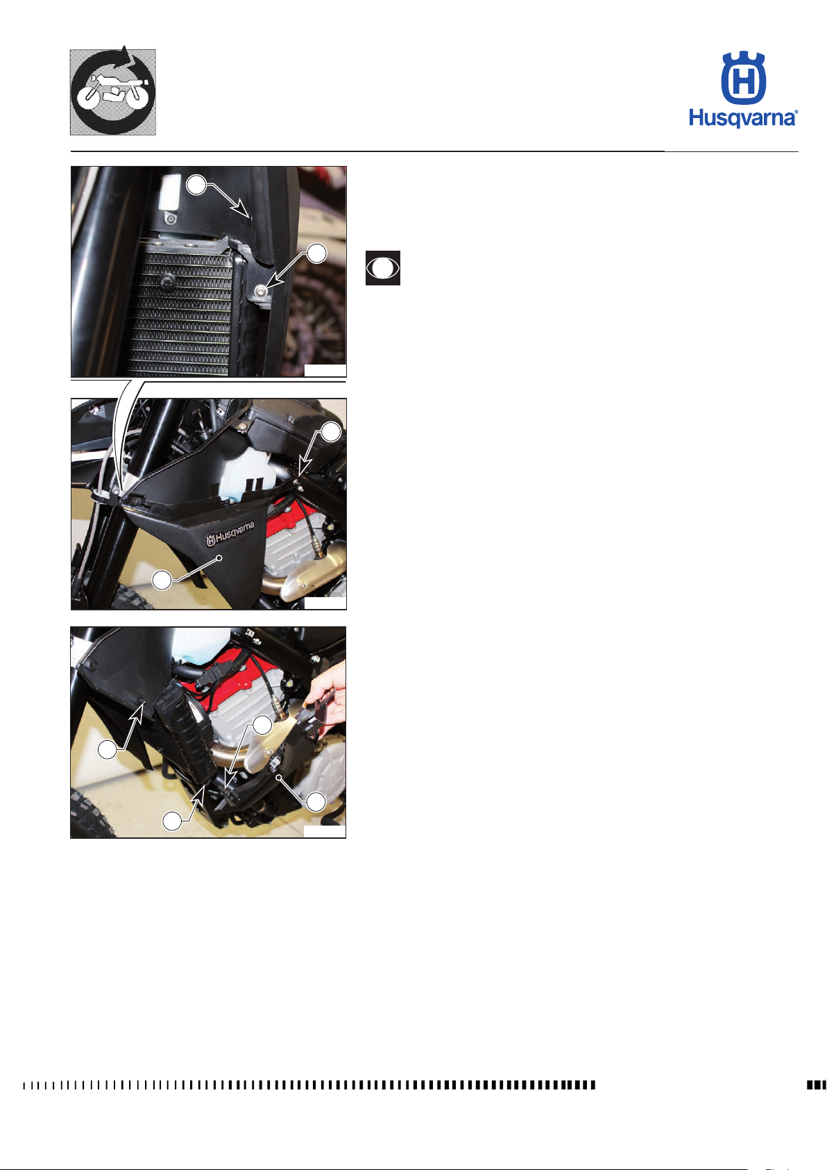
GENERAL PROCEDURES
TR 650 TERRA 2013 - TR 650 STRADA 2013
Removal of radiator guards
3
1
H11821
Remove the side panels as described in the relevant paragraph.
- Unscrew the screws (1).
- Put the guard (2) out and release it from the ttings (top tting with clip (3),
bottom tting with rubber ring (4)).
Use spray grease to make removal and reassembly easier.
- Retrieve the upper clip.
- When reassembling, rst insert the bottom pin (5) in the rubber ring (4), then
the upper clip (3) and nally the screws (1).
1
2
H11820
5
3
2
4
H11822
E.13
Workshop Manual Ed. 09-2012
Page 64
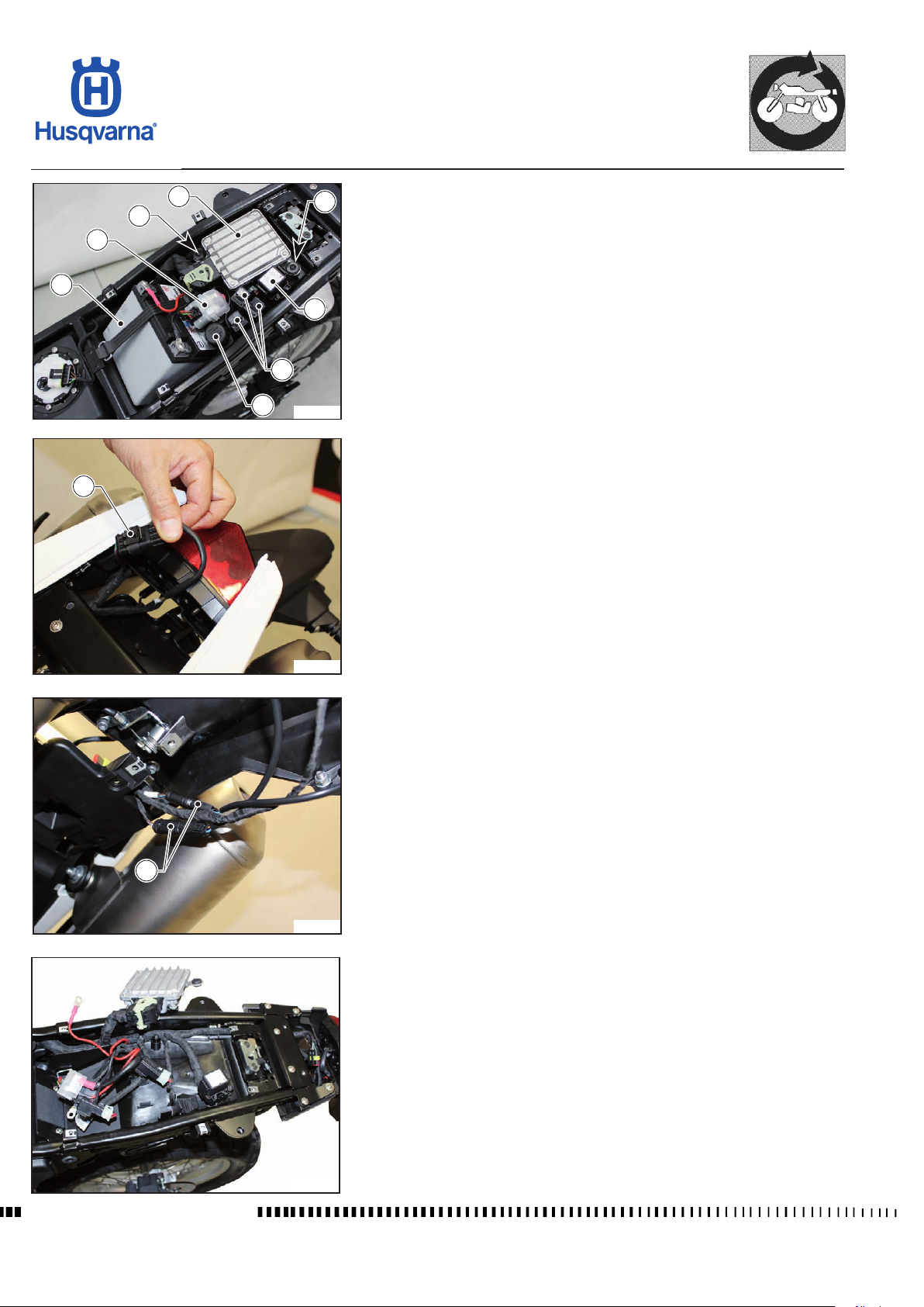
GENERAL PROCEDURES
TR 650 TERRA 2013 - TR 650 STRADA 2013
5
4
6
Removal of lower tail cover
4
Remove the saddle, the luggage rack, the rear tail cover, the antitheft device
compartment cover, the side panels and the rear panels as described in the
relevant paragraphs.
- Remove the battery (1) as described in the relevant paragraph.
1
8
7
9
H11823
- Disconnect the tail light connector (2) and the turning indicator connectors
(3).
2
- Unscrew the screws (4) that secure the ECU (5).
- Remove the starter relay (6), the relays (7), the fuse box (8) and the diagnosis
socket (9) from their supports.
H11824
3
H11825
- Free the lower cover from the cable harness and the electrical components.
Workshop Manual Ed. 09-2012
H11826
E.14
Page 65
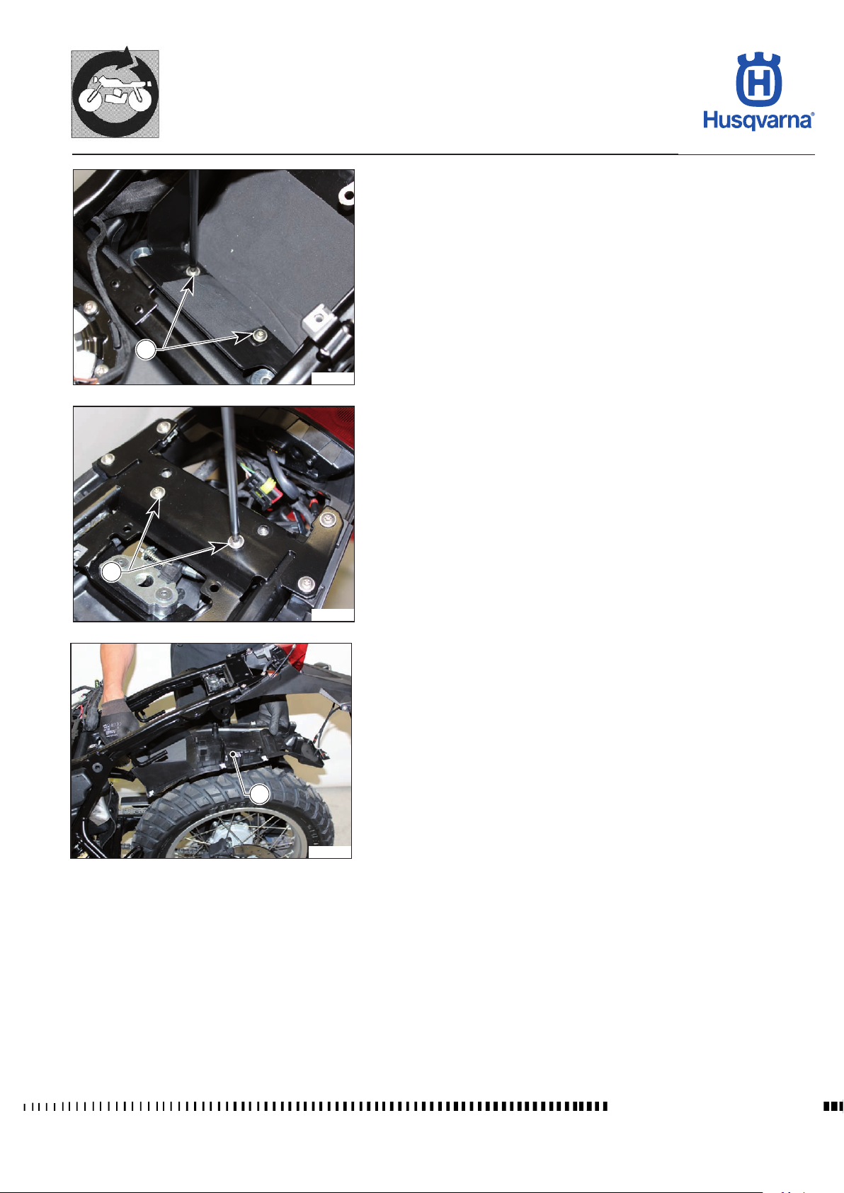
10
GENERAL PROCEDURES
TR 650 TERRA 2013 - TR 650 STRADA 2013
- Unscrew the two front screws (10) in the battery compartment and the two
rear screws (11) and then remove the lower cover (12).
H11827
11
H11828
12
H11829
E.15
Workshop Manual Ed. 09-2012
Page 66
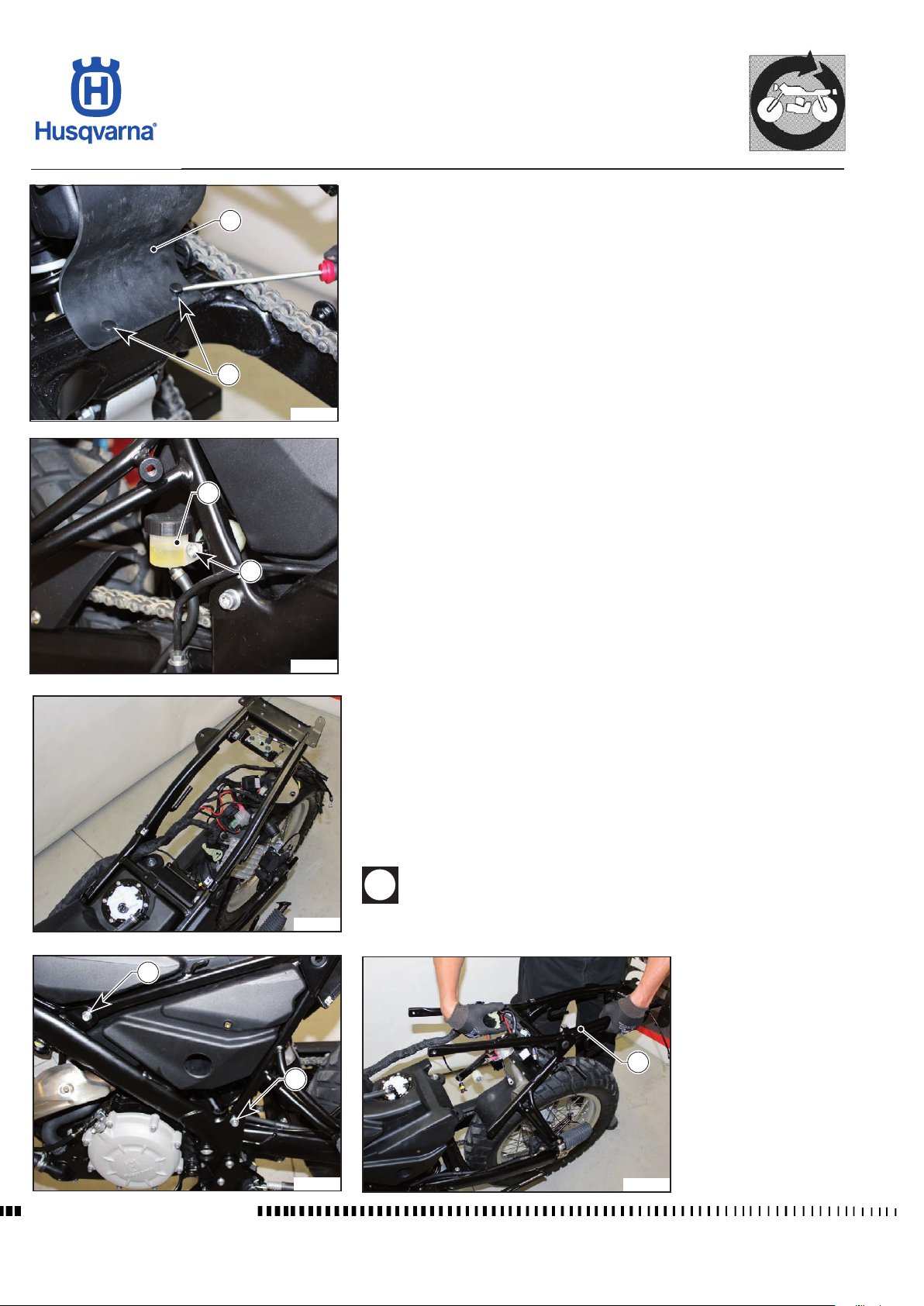
GENERAL PROCEDURES
TR 650 TERRA 2013 - TR 650 STRADA 2013
Removal of tail chassis
Remove the lower tail cover and the number plate holder as described in the
2
1
H11830
4
relevant paragraphs.
- Unfasten the two clips (1) of the shock absorber protection (2).
- Unscrew the screw (3) fastening the rear brake uid tank (4).
3
H11831
- Move the cable harness with the electrical components in the inner part of
the chassis and place them on the rear wheel.
- Unscrew the four screws (5) and slide the chassis out from the rear (6).
When reassembling, make sure that you put the cable harness back
H11832
in the same position it was before.
5
Workshop Manual Ed. 09-2012
5
H11833
6
H11834
E.16
Page 67
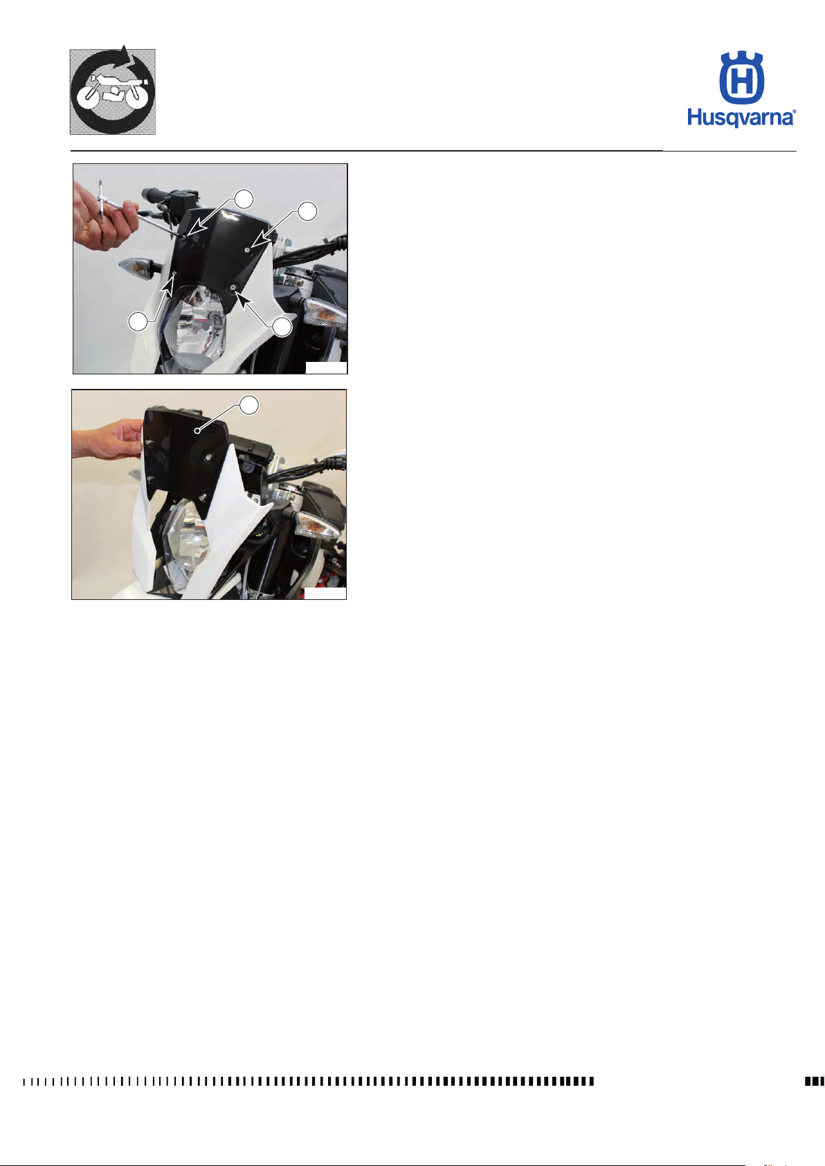
GENERAL PROCEDURES
TR 650 TERRA 2013 - TR 650 STRADA 2013
Front fairing removal
- Unscrew the screws (1) and remove the front fairing (2).
1
1
1
1
H11835
2
H11836
E.17
Workshop Manual Ed. 09-2012
Page 68
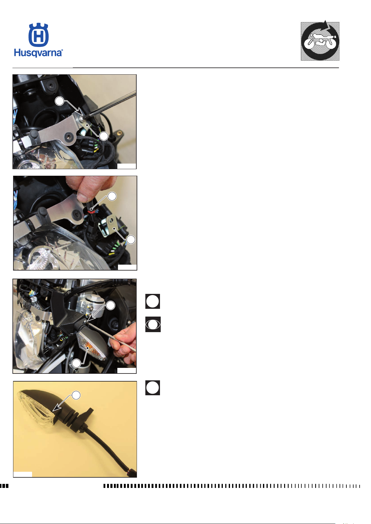
GENERAL PROCEDURES
TR 650 TERRA 2013 - TR 650 STRADA 2013
Front turning indicator removal
- Remove the front fairing as described in the relevant paragraph.
- Unscrew the screw (1) and remove the support (2).
1
2
H11898
- Disconnect the left turning indicator connector (3).
3
2
H11899
- Unscrew the screw (4) and remove the entire left turning indicator (5).
4
Retrieve the nut after unscrewing the screw (4).
Repeat the above steps to remove the right turning indicator.
5
H11900
6
During the reassembly of the turning indicators, make sure that the
water discharge hole (6) faces downwards and that the connector
of the right-hand turning indicator is connected to the connector
marked with a white adhesive tape of the bike harness.
H11901
Workshop Manual Ed. 09-2012
E.18
Page 69
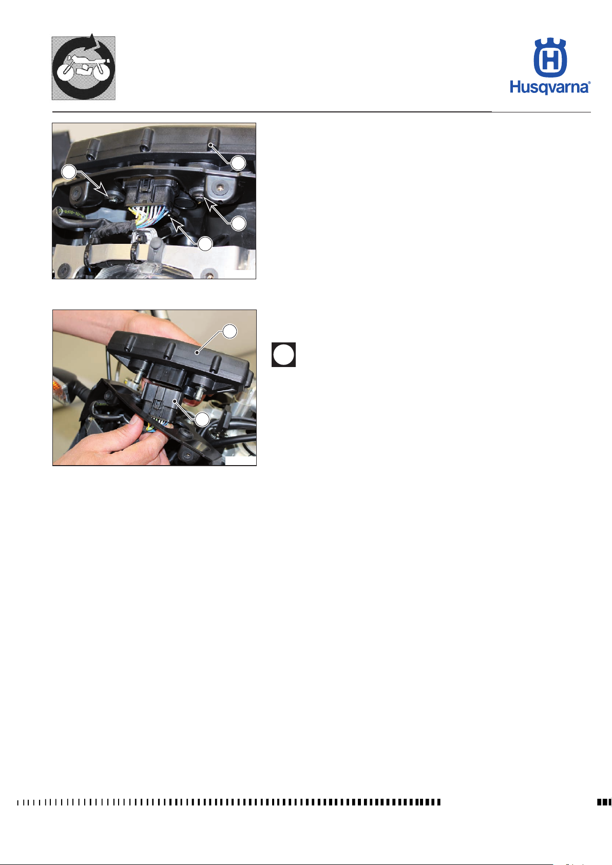
GENERAL PROCEDURES
TR 650 TERRA 2013 - TR 650 STRADA 2013
Combined dashboard removal
- Remove the front fairing as described in the relevant paragraph.
- Remove the clips (1) and raise the dashboard (2).
1
1
2
1
H11902
2
- Disconnect the connector (3) and remove the dashboard (2).
During the reassembly, insert the pins in the special rubbers and
lock the dashboard with the special retaining clips.
After the replacement of the dashboard, it is necessary to connect
the diagnostic tool to the vehicle and follow the wizard.
3
H11903
E.19
Workshop Manual Ed. 09-2012
Page 70
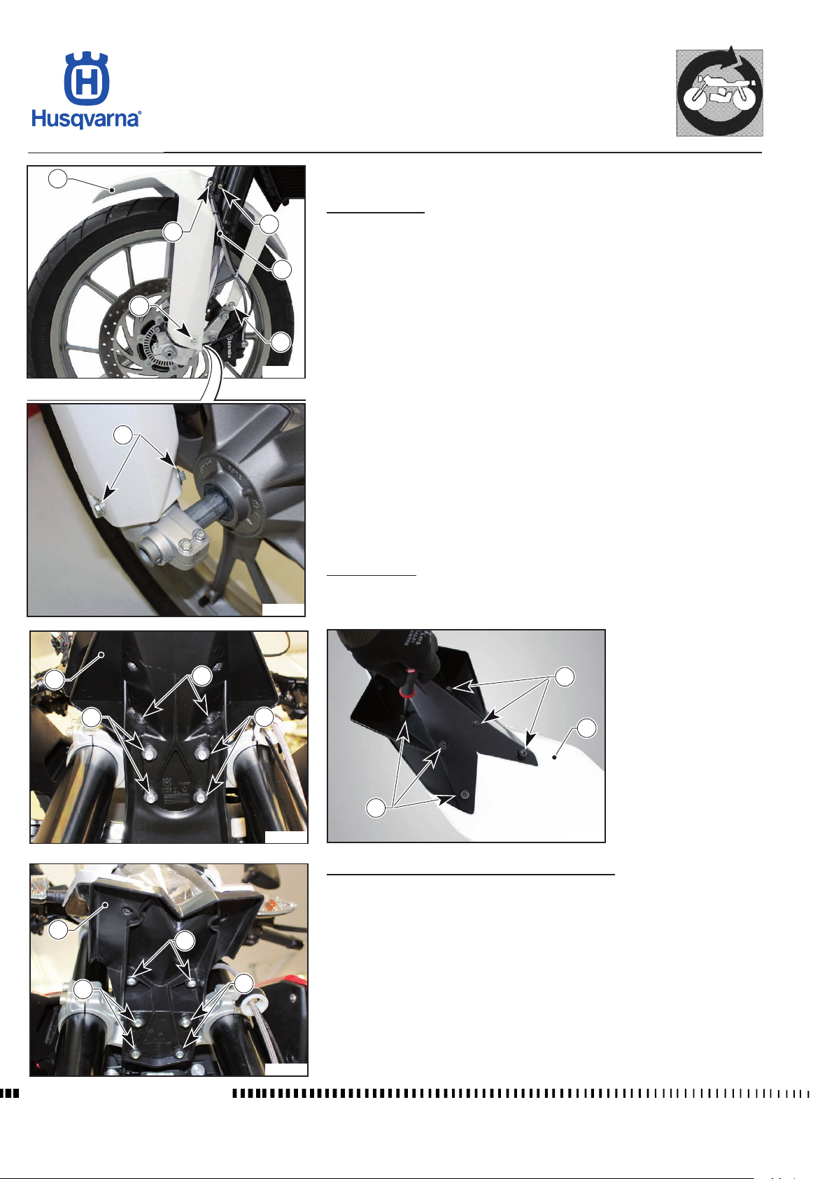
GENERAL PROCEDURES
TR 650 TERRA 2013 - TR 650 STRADA 2013
4
1
1
Removal of front mudguard
STRADA version:
- Unscrew the two screws (1) and release the front brake hose (2) from the
cable ring.
- Unscrew the screws (3) on both sides and remove the mudguard (4).
2
3
3
H11904
3
TERRA version:
- Unscrew screws (8) and screws (9) and then remove the front mudguard
H11905
(10).
- To disassemble the mudguard (10), unscrew the screws (11).
10
9
8
8
11
10
11
H11907
Removal of upper pushrod ON STRADA VERSION:
- Unscrew screws (5) and screws (6) and then remove the pushrod (7).
7
5
6
5
H11906
H11908
Workshop Manual Ed. 09-2012
E.20
Page 71
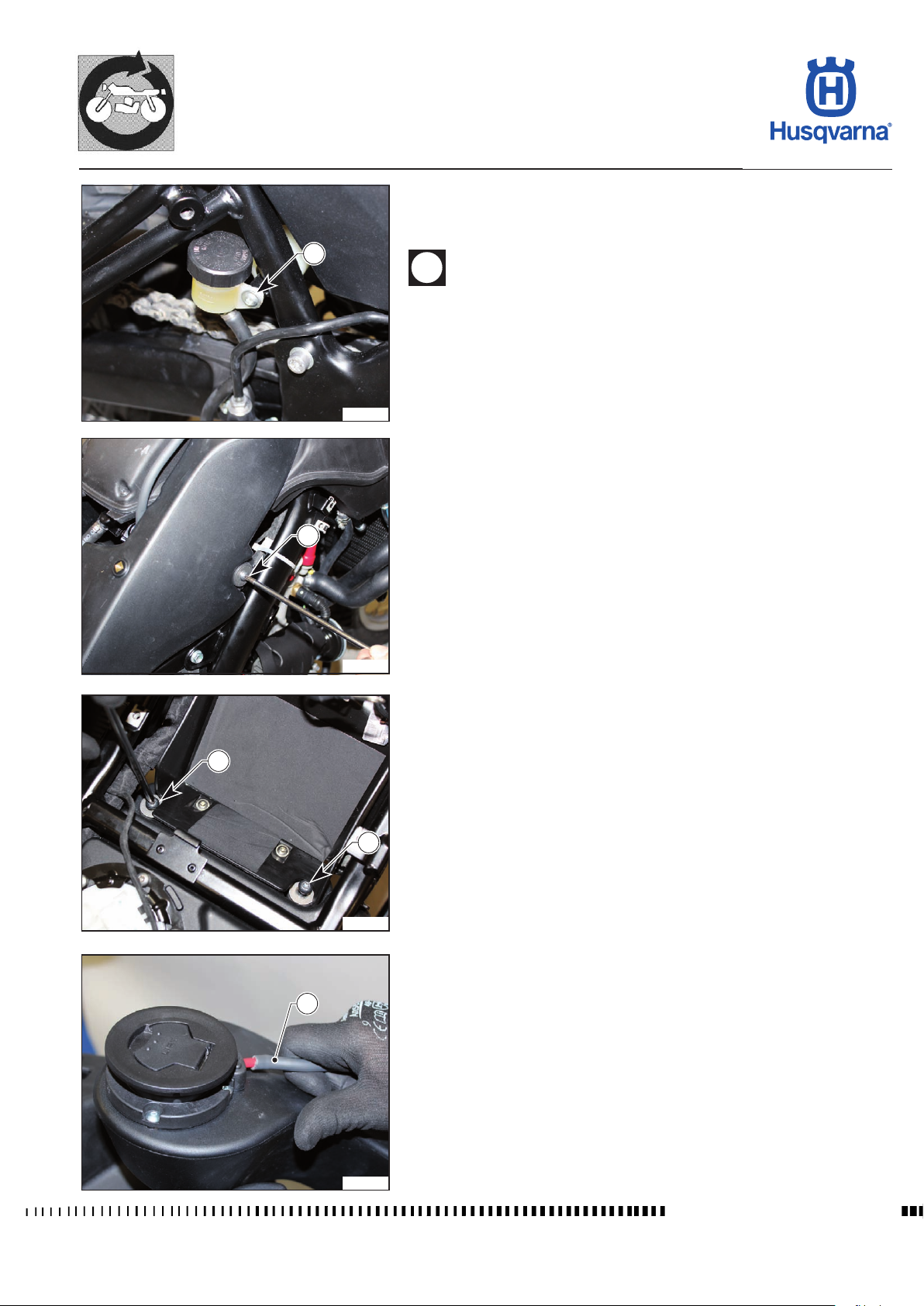
GENERAL PROCEDURES
TR 650 TERRA 2013 - TR 650 STRADA 2013
Removal of fuel tank
Remove the saddle, side panels and rear panels, the battery, silencers and the
central exhaust manifold.
1
While disassembling the tank, do not bend, force or pull the cable
harness too hard.
- Unscrew the screw (1) and remove the rear brake oil tank.
H11909
- Unscrew the screw (2) on the right side of the tank.
2
H11910
- Unscrew the two screws (3) on the battery compartment.
3
3
H11911
- Disconnect the breather hose (4).
4
H11912
Workshop Manual Ed. 09-2012
E.21
Page 72
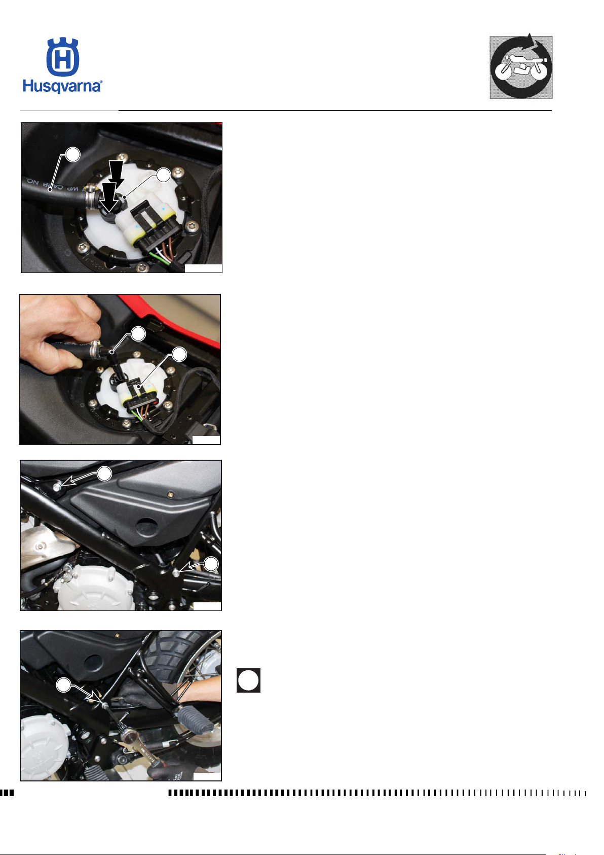
12
GENERAL PROCEDURES
TR 650 TERRA 2013 - TR 650 STRADA 2013
- Disconnect the fuel pipe (12) by pressing the ring nut (5) and lifting the union
(6).
5
H111028
- Disconnect the connector (7) from the fuel pump.
6
7
H11914
8
- Unscrew the two screws (8) on both sides that secure the upper part of the
rear chassis and loosen the lower screws (9).
9
H11915
- Lower the rear chassis with the tank and place it with a support on the rear
wheel and then unscrew the lower screws (9).
9
Workshop Manual Ed. 09-2012
When lowering the chassis, the tank interferes with the lter box
and the fuel delivery pipe; make sure you do not break the pipe
tting on the throttle body.
H11916
E.22
Page 73
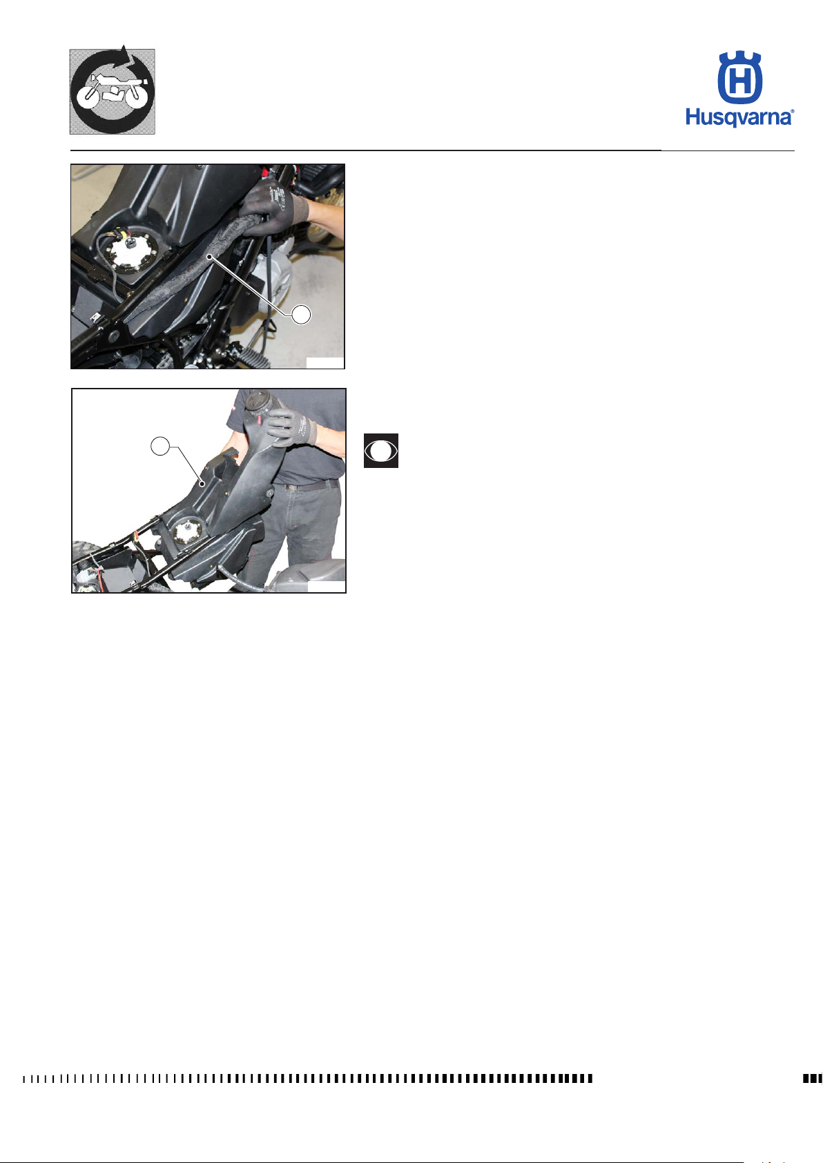
GENERAL PROCEDURES
TR 650 TERRA 2013 - TR 650 STRADA 2013
- Remove the central part of the cable harness (10) from the chassis.
10
H11917
- Turn the chassis to the right and remove the tank (11).
11
Follow the same steps in reverse order to reassemble the tank and
make sure you put the cable harness back in the same position it
was before.
H11918
E.23
Workshop Manual Ed. 09-2012
Page 74
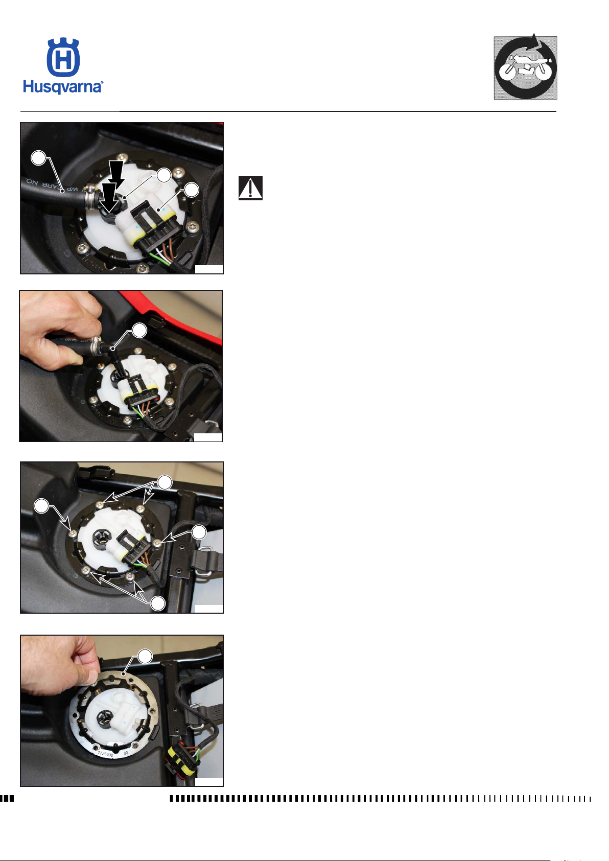
GENERAL PROCEDURES
TR 650 TERRA 2013 - TR 650 STRADA 2013
Fuel pump removal
- This operation cannot be performed when the tank is completely full because
the fuel will leak out: we recommend emptying the tank by drawing the fuel
2
3
1
H11919
4
through suction using a special tool.
Fuel vapours are extremely harmful. Make sure you do not inhale
them and work in ventilated areas.
- Disassemble the saddle as described in the relevant paragraph.
- Disconnect the connector (1).
- Disconnect the fuel pipe (2) by pressing the ring nut (3) and lifting the union
(4).
H11920
5
- Undo screws (5) and remove the ring nut (6).
5
5
5
H11921
6
Workshop Manual Ed. 09-2012
H11922
E.24
Page 75
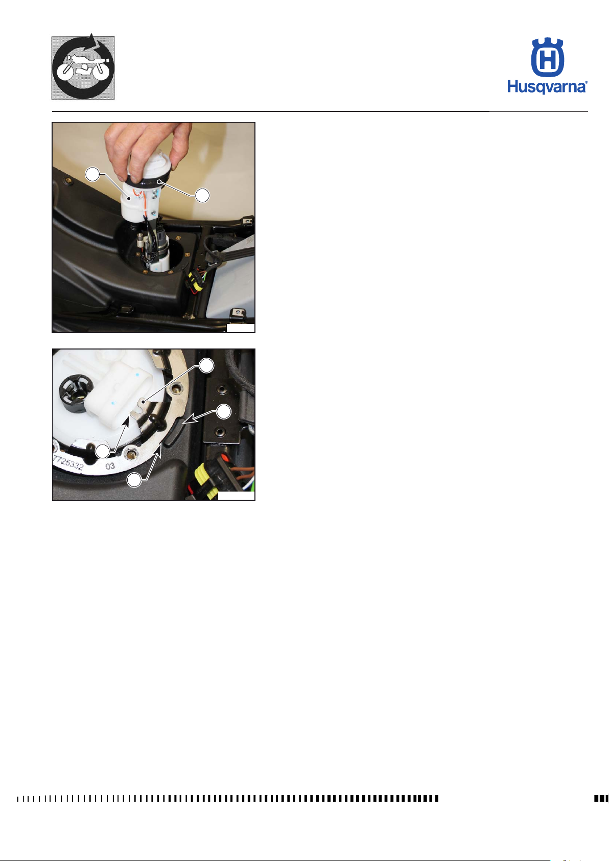
GENERAL PROCEDURES
TR 650 TERRA 2013 - TR 650 STRADA 2013
- Remove the pump (7) from the tank.
- Check the seal (8) for wear, change it if dry or damaged.
7
8
H11923
10
- When reassembling the pump, align the tab (9), located under the connector, with the seat (10) of the ring nut and the seat (11) of the ring nut with the
bump (12) on the tank.
- Tighten the screws (5) to torque and reconnect the union (4) and the connector (1).
12
9
11
H111023
E.25
Workshop Manual Ed. 09-2012
Page 76
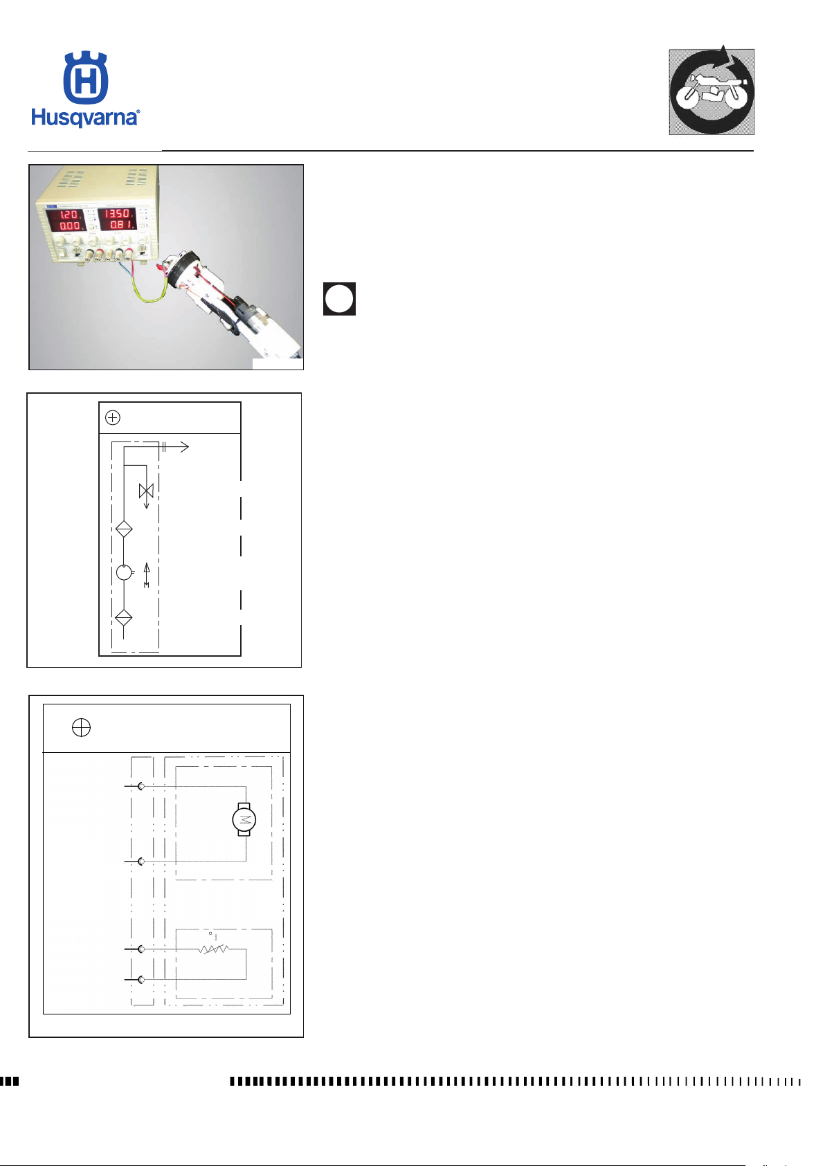
HYDRAULIC
DIAGRAM
GENERAL PROCEDURES
TR 650 TERRA 2013 - TR 650 STRADA 2013
Fuel pump inspection
Remove the pump as described in the relevant paragraph.
- Connect the positive pole (12V) of the power supply to the pin of the red
cable in the pump connector;
Connect the negative pole of the power supply to the negative pin in the
pump connector.
Never keep the pump connected to the power supply unit for more
than 3 seconds in a row.
H111029
OUT
ELECTRIC
DIAGRAM
FUEL SYSTEM
GROUND
REGULATOR
FINE FILTER
PUMP
FUEL
PRE-FILTER
H10963
SIGNAL
GROUND
Workshop Manual Ed. 09-2012
H111030
E.26
Page 77
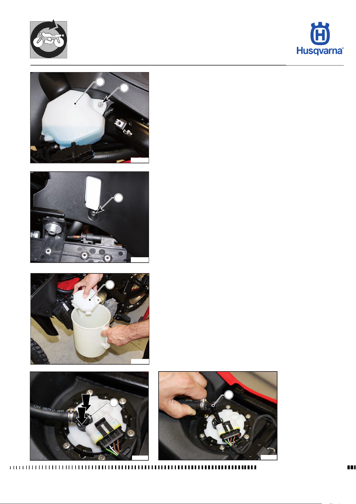
GENERAL PROCEDURES
TR 650 TERRA 2013 - TR 650 STRADA 2013
Removal of lter box
3
1
H11925
2
Remove the front panels, the radiator guards, the rear panels, the exhaust silencers and the central exhaust manifold, as described in the relevant paragraphs.
- Unscrew the side screw (1) and the front screw (2), then remove the tank (3)
at the rear of the motorcycle and pour the coolant in a container.
H11926
3
H11927
- Disconnect the fuel pipe by pressing the ring nut (4) and lifting the union (5).
5
4
H11928
H11929
Workshop Manual Ed. 09-2012
E.27
Page 78
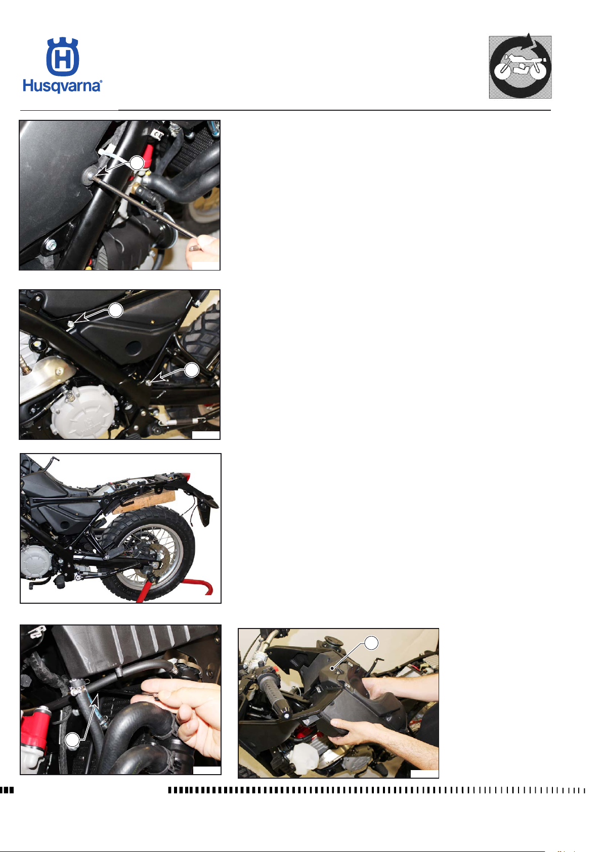
GENERAL PROCEDURES
TR 650 TERRA 2013 - TR 650 STRADA 2013
- Unscrew the screw (6) on the right side of the tank.
6
H11930
- Unscrew the two upper screws (7) of the chassis and loosen the two lower
7
screws (8).
8
H11931
H11932
- Rock the rear chassis with the fuel tank towards the rear of the motorcycle
by placing a suitable support on the rear wheel so that the cable harness is
not too tight.
- Unscrew the screw (9) on the lower right-hand part of the lter box.
- Lift the lter box (10) by releasing it form the special ttings and from the
throttle body.
10
9
Workshop Manual Ed. 09-2012
H11933
H11934
E.28
Page 79
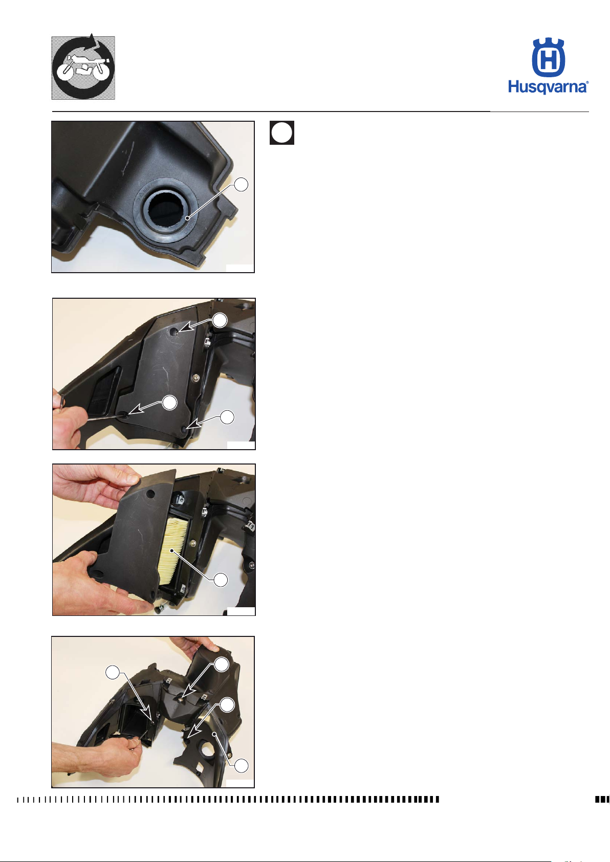
GENERAL PROCEDURES
TR 650 TERRA 2013 - TR 650 STRADA 2013
Check that the rubber seal element (11) is not worn/damaged; re-
place if necessary.
When reassembling, t the lter box onto the throttle body until the seal element
11
H11935
(11) is pushed all the way down. To make it easier to insert, use special lubricants
and slightly rock the lter box.
1
Dismantling of lter box
- Unscrew the three screws (1) and remove the air lter (2) with its support.
1
1
H11936
2
H11937
- Unscrew the screws (3) to remove the front cover (4) of the lter box.
3
3
3
4
H11938
Workshop Manual Ed. 09-2012
E.29
Page 80
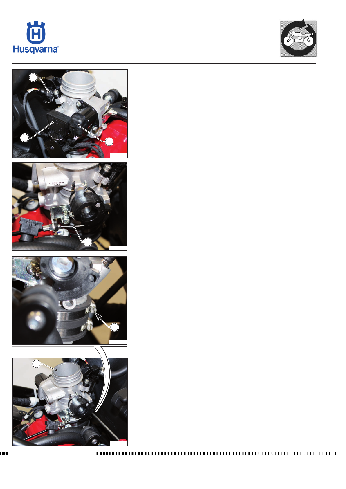
GENERAL PROCEDURES
TR 650 TERRA 2013 - TR 650 STRADA 2013
Throttle body removal
1
- Remove the lter box as described in the relevant paragraph.
- Disconnect the injector connector (1), the throttle position sensor connector
(2) and the idle speed adjustment actuator connector (3).
2
3
H11939
- Disconnect the throttle cable (4).
4
H11940
- Loosen the clamp (5).
6
Workshop Manual Ed. 09-2012
5
H11941
- Remove the throttle body (6) with the fuel supply pipe.
NOTE: The electromechanical parts have a set position. If replaced, they
must be reassembled in exactly the same position.
H11942
E.30
Page 81
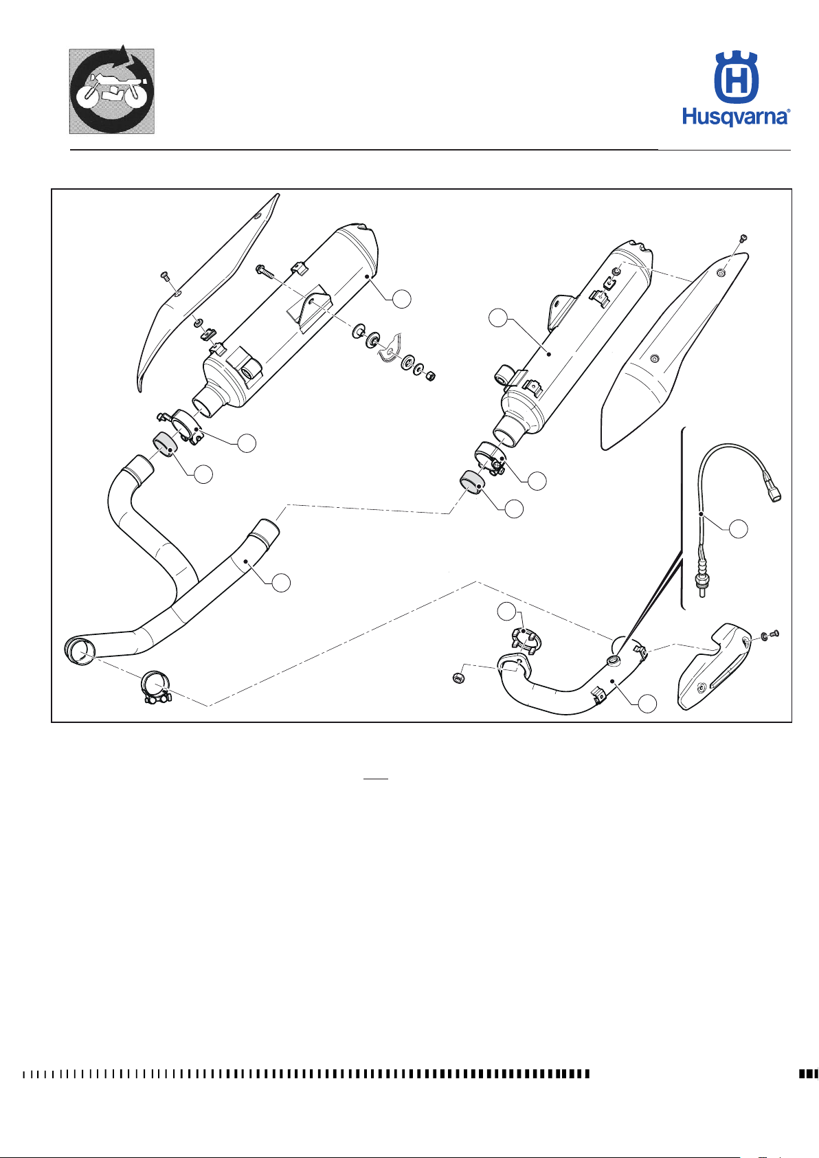
GENERAL PROCEDURES
TR 650 TERRA 2013 - TR 650 STRADA 2013
Exhaust system removal
2
1
3
4
3
4
7
5
8
6
Key:
1) Left silencer
2) Right silencer
3) Clamps
4) Gaskets
5) Central manifold
6) Manifold
7) Lambda sensor
8) Gasket
H11943
E.31
Workshop Manual Ed. 09-2012
Page 82
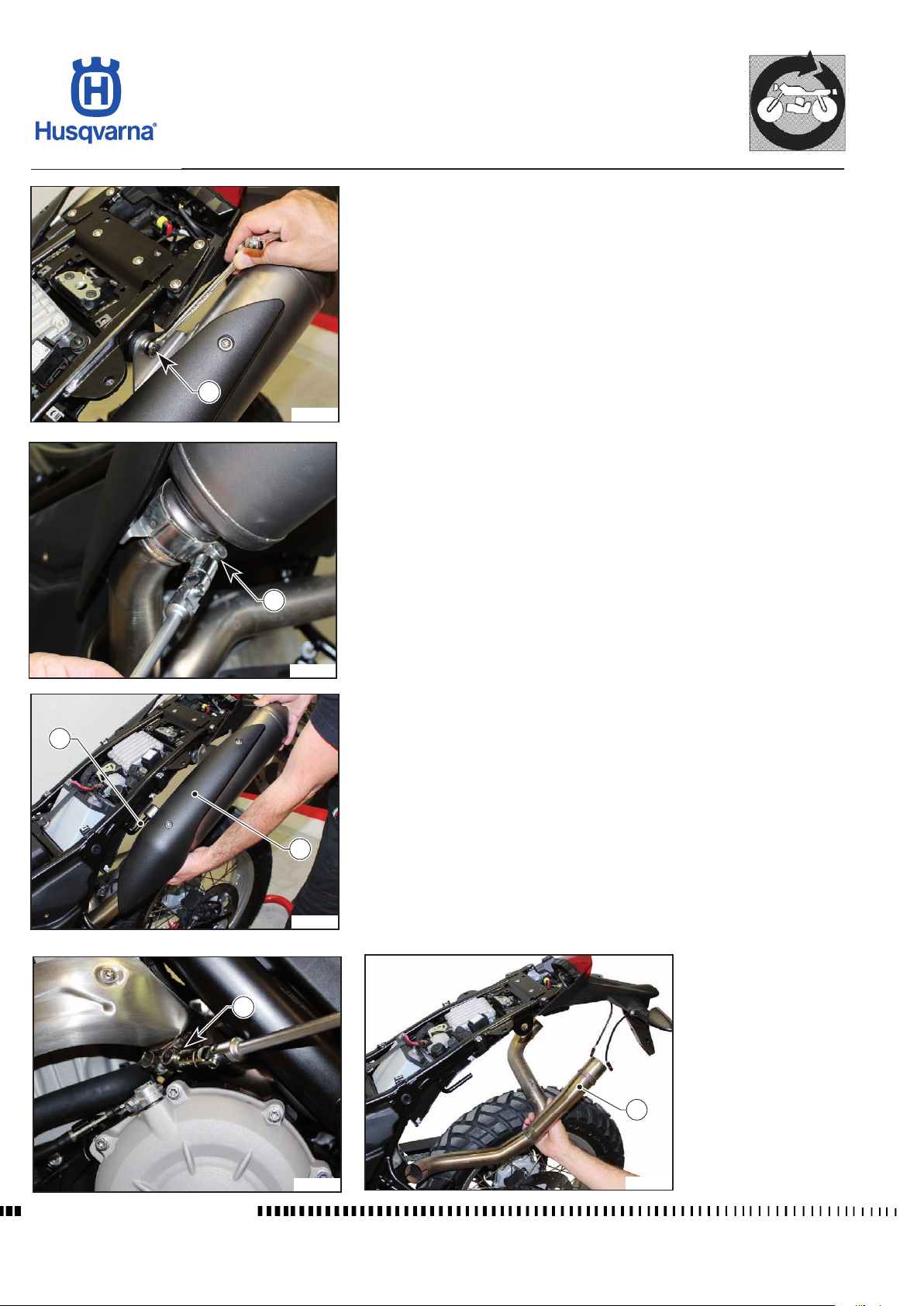
GENERAL PROCEDURES
TR 650 TERRA 2013 - TR 650 STRADA 2013
Exhaust system removal
Remove the saddle as described in the relevant paragraph.
- Unscrew the rear support (1) on both sides.
1
H11944
- Loosen the clamps (2) on both sides and remove both silencers (3) by sliding
them out of the support (4).
2
H11945
4
3
H11946
- Loosen the clamp (5) and remove the central manifold (6).
5
Workshop Manual Ed. 09-2012
H11947
6
H11948
E.32
Page 83
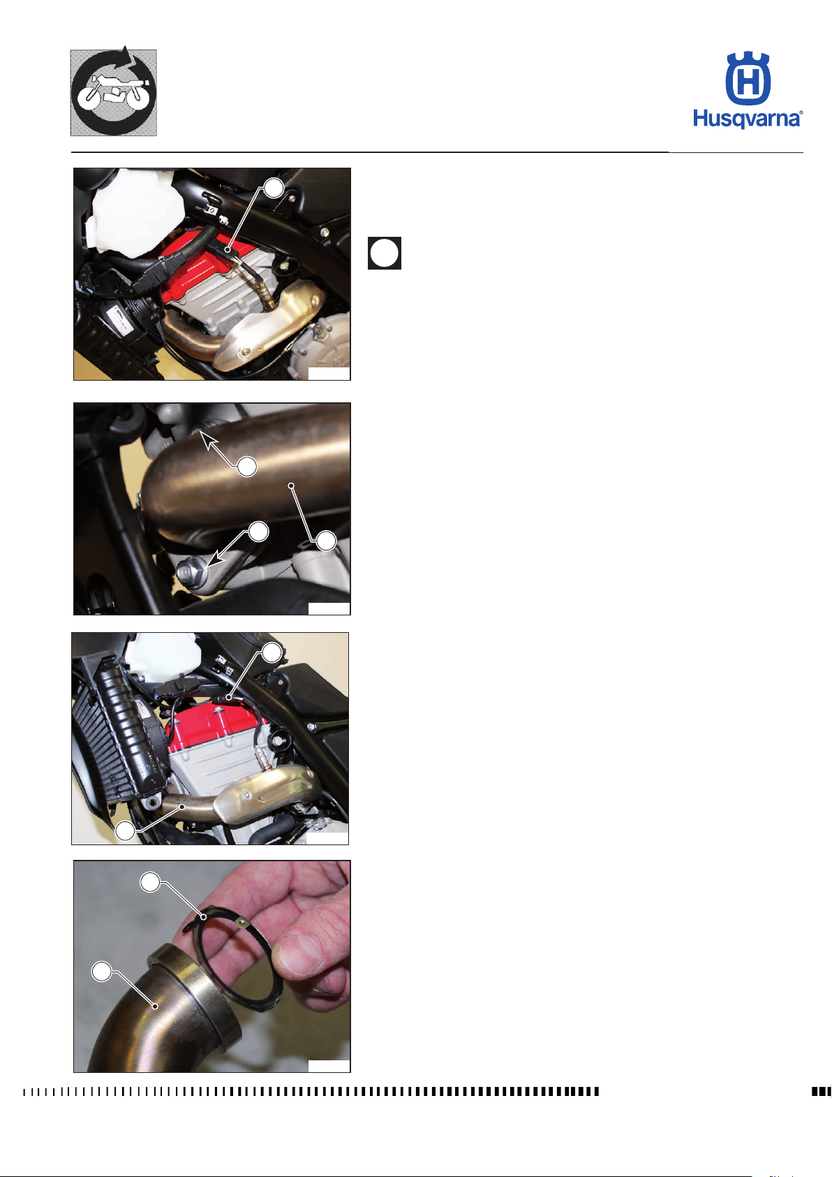
GENERAL PROCEDURES
TR 650 TERRA 2013 - TR 650 STRADA 2013
- Disconnect the Lambda sensor connector (7).
7
H11949
8
- Undo the nuts (8) fastening the exhaust manifold (9) to the cylinder head,
remove the manifold and retrieve the steel gasket (10).
When reassembling, t the steel gasket (10) onto the manifold
making sure that the support tabs are inserted on the pipe.
8
9
H11951
7
9
H11950
10
9
H11952
Workshop Manual Ed. 09-2012
E.33
Page 84
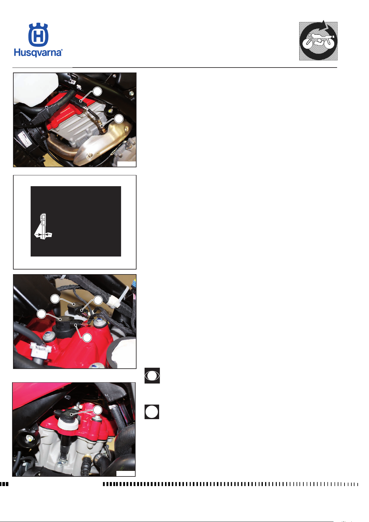
GENERAL PROCEDURES
TR 650 TERRA 2013 - TR 650 STRADA 2013
Lambda sensor removal
- Disconnect the connector (1).
1
2
H11953
- Unscrew the Lambda sensor (2) from the exhaust manifold.
Coil / Stick-Coil removal and spark plug test
- Remove the lter box as described in the relevant paragraph.
- Disconnect the connectors (1) and (2) from the coils/stick coils (3) and (4).
- Lift the coils/stick coils (3) and (4) to remove them from the cylinder head.
0,6 mm (±0,1 mm)
0.024 in. (±0.004 in.)
4
3
Spark plug electrodes gap shall be 0,6 mm ± 0,1 mm (0,024 in. ± 0,004 in).
A wider gap may cause difculties in starting the engine and overload the coil.
A gap that is too narrow may cause difculties when accelerating, when idling
or poor performance at low speed.
Clean off any dirt around spark plug base before removing the spark plug.
H11954
2
1
H11955
- Unscrew the spark plugs using the special spanner to remove them from the
cylinder head.
It is very useful to examine the state of the spark plug just after it has been
removed from the engine since the scale deposits on the plug and the colour of
the insulator provide useful indications.
Correct heat rating: the tip of the insulator should be dry and the colour should
be light brown or grey.
High heat rating: in this case, the insulator tip is dry and covered with dark
deposits.
Low heat rating: in this case, the spark plug has overheated and insulator tip is
vitried (glazed), white or grey in colour.
When reassembling, place the coil/stick coil (4) with the white rim
on the external right-hand part of the engine and connect it using
the connector (2) with the white ring to the cable.
Workshop Manual Ed. 09-2012
4
If the position of the two coils/stick coils or the connectors is in-
verted, the engine will run erratically.
H11956
E.34
Page 85
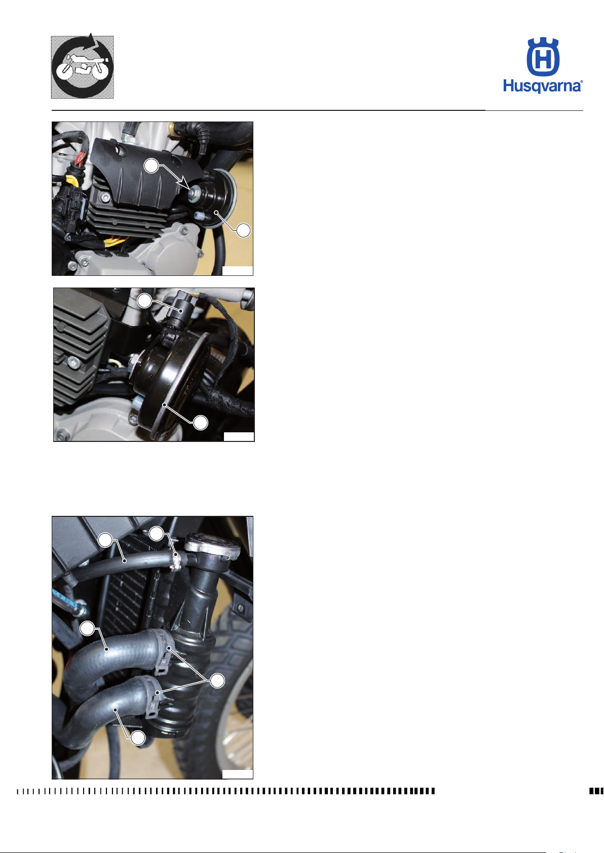
GENERAL PROCEDURES
TR 650 TERRA 2013 - TR 650 STRADA 2013
Horn removal
- Undo the nut (1).
- Disconnect the connector (2) and remove the horn (3).
1
3
H11957
2
3
H11958
5
4
2
Radiator removal
- Remove the saddle and the radiator guards, as described in the relevant
paragraphs.
- Drain the coolant as indicated in the relevant paragraph.
- Use suitable pliers to open the clamps (1) that fasten the pipes (2) and (3)
that connect the radiator / engine.
- Remove the two pipes (2) and (3) from the radiator.
- Open the clamp (4) and remove the pipe (5) that connects the expansion
tank to the radiator.
1
3
H11959
Workshop Manual Ed. 09-2012
E.35
Page 86
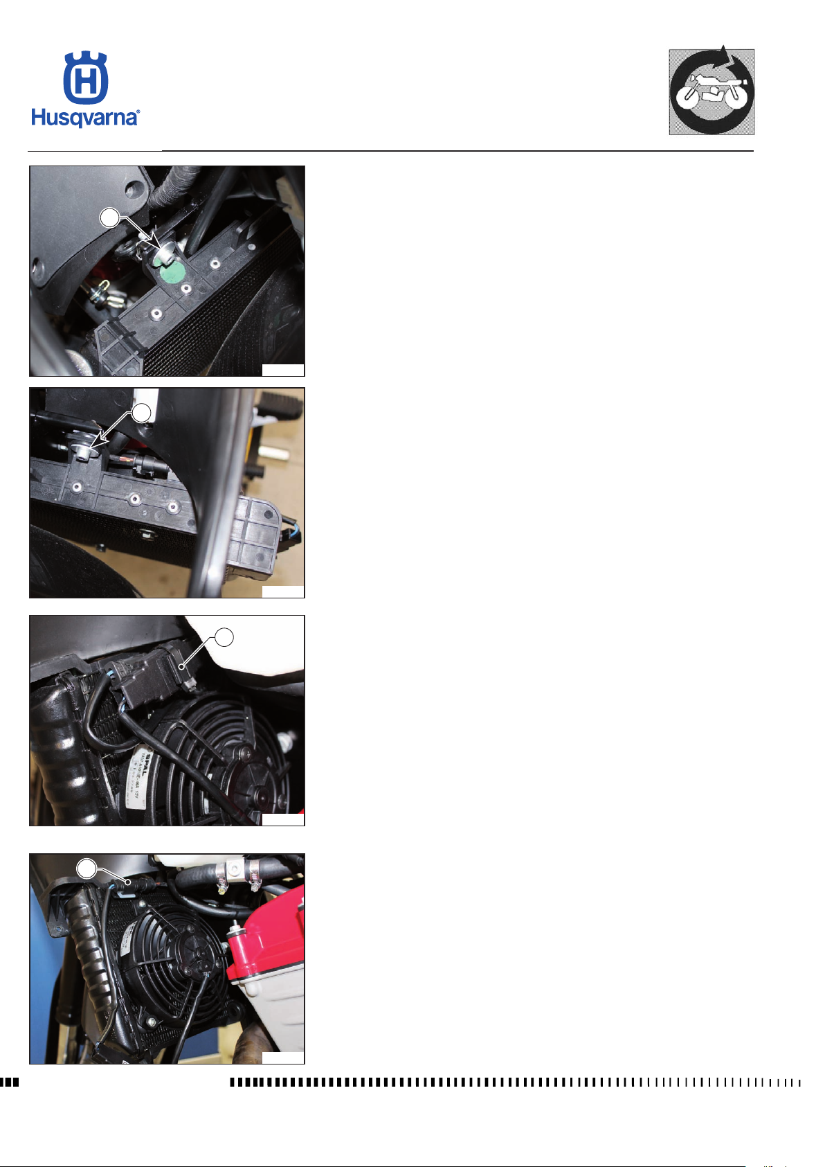
GENERAL PROCEDURES
TR 650 TERRA 2013 - TR 650 STRADA 2013
- Unscrew the two upper screws (6).
6
H11960
6
H11961
7
H11962
8
- Cut the clamp (7) that secures the electric fan cable harness.
- Disconnect the electric fan connector (8).
Workshop Manual Ed. 09-2012
H11963
E.36
Page 87
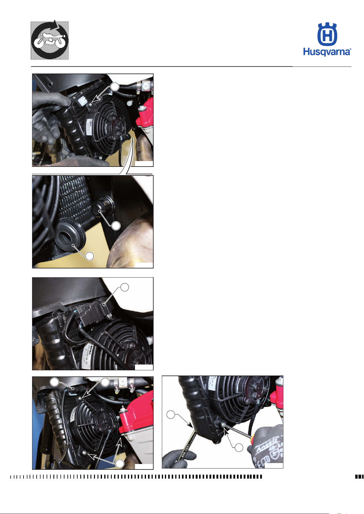
GENERAL PROCEDURES
TR 650 TERRA 2013 - TR 650 STRADA 2013
- Slide the radiator (9) out from the left and remove it from its special support
9
H11964
(10).
- When reassembling, make sure that the support (10) is correctly inserted in
the retaining pin (11).
11
10
H11965
Removal of electric fan
1
H11966
2
3
- Remove the left radiator guard as described in the relevant paragraph.
- Cut the clamp (1) and remove the cable harness.
- Disconnect the connector (2).
- Unscrew the three screws (3) by locking the nut (4) on the other side.
- Remove the electric fan.
4
3
3
H11967
E.37
H11968
Workshop Manual Ed. 09-2012
Page 88
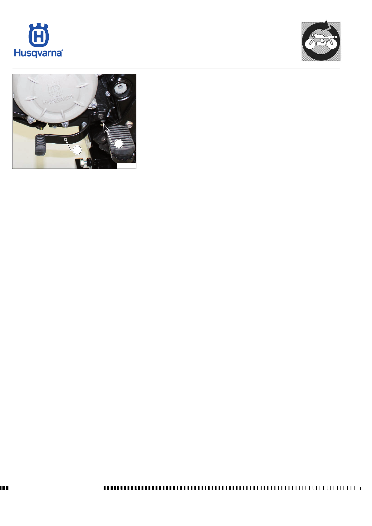
GENERAL PROCEDURES
TR 650 TERRA 2013 - TR 650 STRADA 2013
Gearbox lever removal
- Loosen the screw (1) and remove the lever (2).
1
2
H11969
Workshop Manual Ed. 09-2012
E.38
Page 89
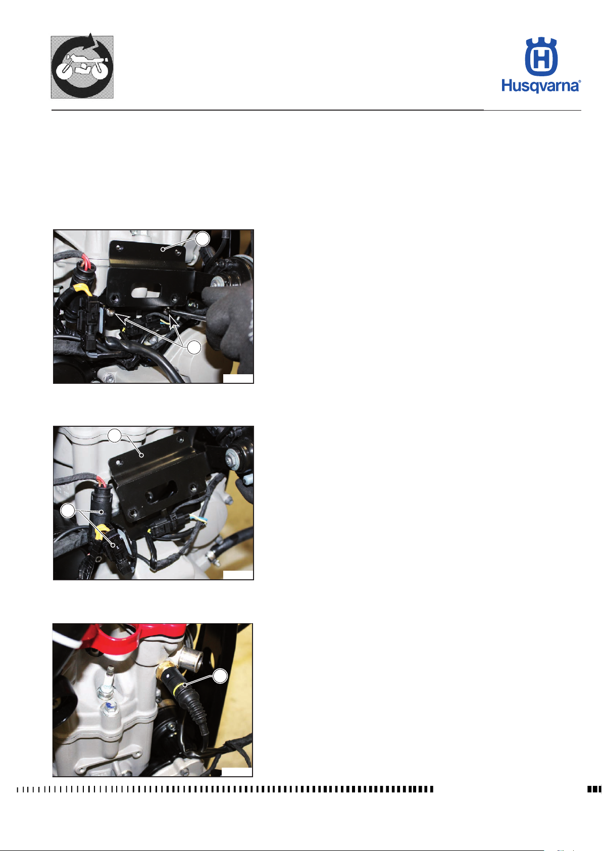
GENERAL PROCEDURES
TR 650 TERRA 2013 - TR 650 STRADA 2013
Removal of engine
Remove the following components in order as described in the relevant paragraphs/sections:
- exhaust;
- fuel tank;
- lter box;
- throttle body;
- sprocket casing;
- voltage regulator.
1
- Remove the voltage regulator support plate (1) by unscrewing the screws
(2).
2
H11970
1
- Disconnect the connectors (3) and remove the plate (1) with the horn.
3
H11971
4
H11972
- Disconnect the coolant temperature sensor connector (4).
Workshop Manual Ed. 09-2012
E.39
Page 90
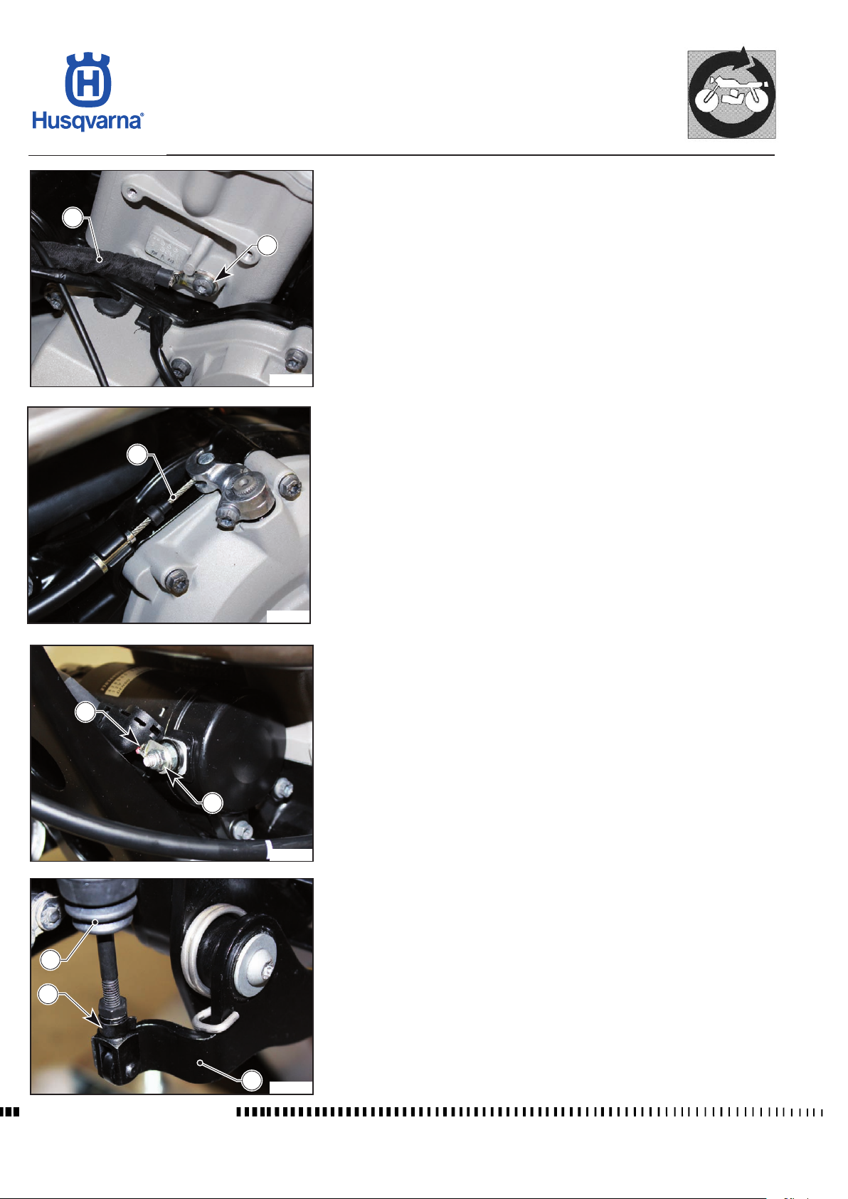
GENERAL PROCEDURES
TR 650 TERRA 2013 - TR 650 STRADA 2013
- Unscrew the screw (5) and disconnect the ground cable (6).
6
5
H11973
- Remove clutch cable (7).
7
11
10
H11974
- Unfasten the nut (8) of the starter motor power supply cable (9).
9
8
H11975
- Remove the clip (10) and remove the master cylinder (11) from the brake
lever (12).
Workshop Manual Ed. 09-2012
12
H11976
E.40
Page 91
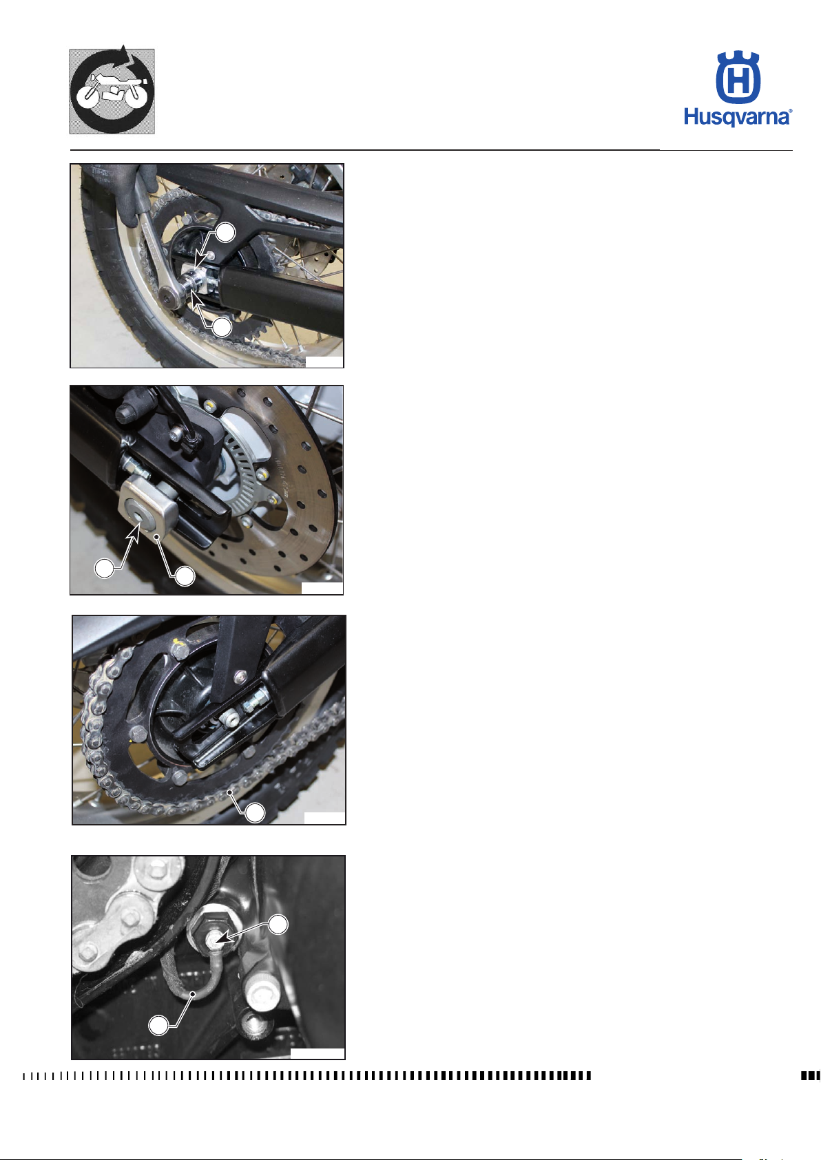
GENERAL PROCEDURES
TR 650 TERRA 2013 - TR 650 STRADA 2013
- Unfasten the nut (13) and remove the chain tensioner slider (14).
14
13
H11977
- Slightly ease the pin (15) in order to release the left slider (16).
15
16
17
26
H11978
- Move the wheel towards the engine to remove the chain (17) from the
sprocket.
H11979
- Remove the screw (26).
- Remove the connection cable (27).
- Place a hoister under the engine and raise slightly.
27
H111031
Workshop Manual Ed. 09-2012
E.41
Page 92
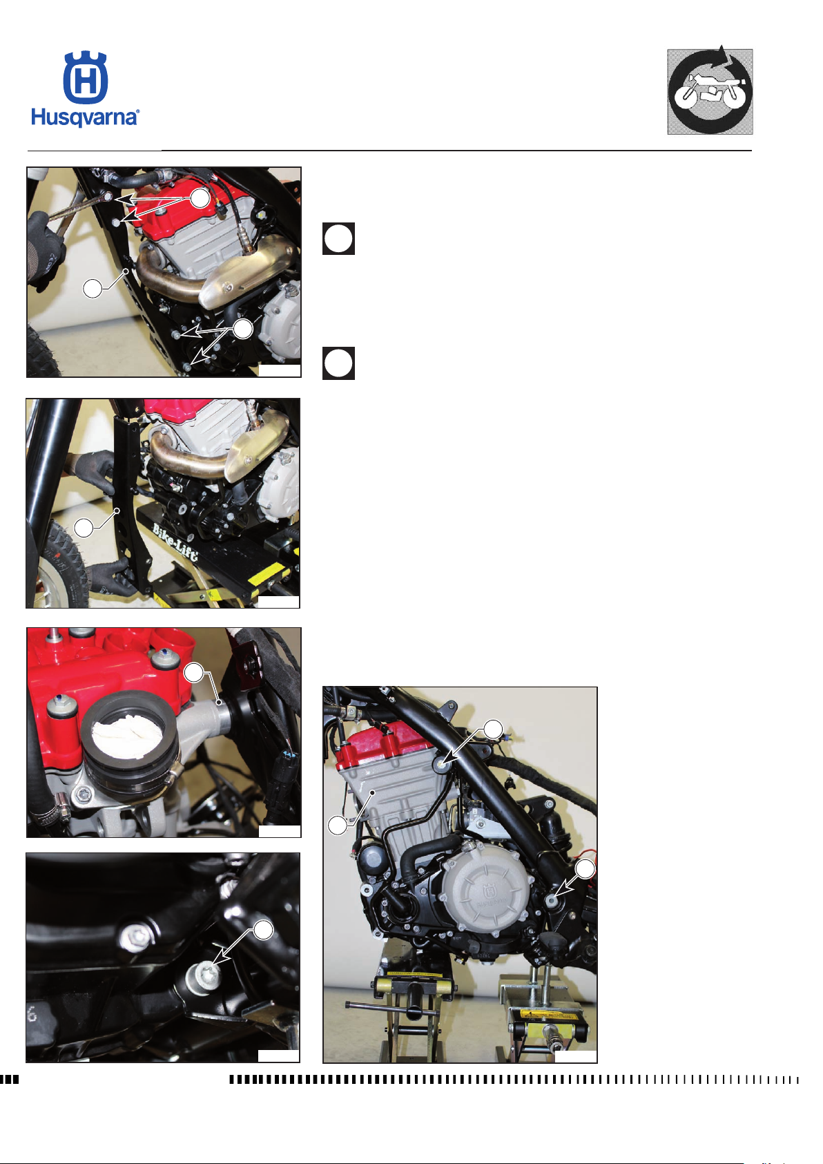
GENERAL PROCEDURES
TR 650 TERRA 2013 - TR 650 STRADA 2013
- Remove the front support cross-member (18) by unscrewing the upper screws
(19) that connect it to the chassis and the lower screws (20) that connect it
19
to the engine.
When reassembling, insert the screws from the left and the nuts
from the right.
18
18
24
20
H11980
H11981
- Unscrew the lower screws (21) that fasten the engine to the chassis.
- Remove the swinging arm pin (22).
- Unscrew the two upper screws (23) that fasten the engine to the chassis.
When reassembling, align the spacer (24) with the right upper screw.
- Lower the hoister keeping the engine (25) balanced and then remove the
engine from the front.
Reassembly of engine
Reassemble by following the steps in reverse order and make sure you:
- reassemble the swinging arm by performing the steps in the relevant para-
graph for adjustment of axial clearance;
- position the cable harnesses correctly;
- tighten the screws (19), (20), (21), (23) and (24) correctly.
Workshop Manual Ed. 09-2012
H11984
21
H11982
23
25
22
H11983
E.42
Page 93
ENGINE SETTINGS AND ADJUSTMENTS
TR 650 TERRA 2013 - TR 650 STRADA 2013
Refer to chapter F4 for all engine tightening torques.
Section
F
F.1
Workshop Manual Ed.09-2012
Page 94

ENGINE SETTINGS AND ADJUSTMENTS
TR 650 TERRA 2013 - TR 650 STRADA 2013
Sommario
VALVE CLEARANCE CHECK ...................................................................... F. 3
Valve clearance check .................................................................................. F. 3
Valve clearance measurement ..................................................................... F.3
PAD REPLACEMENT ................................................................................. F.4
Locking the crankshaft.................................................................................. F.4
Chain tensioner disassembly........................................................................ F.5
Chain guide disassembly.............................................................................. F.5
Camshaft removal ........................................................................................ F.6
Pad replacement .......................................................................................... F.6
Camshaft assembly ...................................................................................... F.6
Chain tensioner installation .......................................................................... F.7
Chain guide installation ................................................................................ F.7
Removal of engine block screw .................................................................... F.7
TIMING CHECK .......................................................................................... F.8
ENGINE PHASING ...................................................................................... F.9
Workshop Manual Ed.09-2012
F.2
Page 95
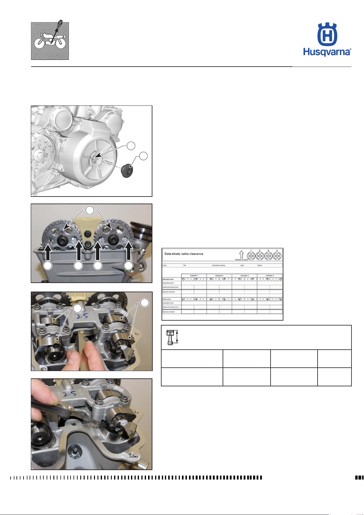
ENGINE SETTINGS AND ADJUSTMENTS
TR 650 TERRA 2013 - TR 650 STRADA 2013
VALVE CLEARANCE CHECK
Remove the coil / spark plug cap, spark plugs and the head cover as described
in chapter "F1".
Valve clearance check
- Remove the screw plug (1).
- Place an Allen wrench into the hole (2) and turn the crankshaft in the normal
sense of rotation until the ignition TDC.
- the marks (3) placed on the crankshaft gears must be coplanar to the sealing
2
1
H11483
surfaces and the holes (4) must face upwards.
- In this position, both cams of the intake and exhaust camshafts must face
upwards and be at the same angle relative to the upper face of the head.
4
3 3 3 3
4
H11485
5
H11486
Valve clearance measurement
Measure valve clearance using a feeler between the cam and valve bucket both
for the intake (4) and exhaust (5) cams.
Note down the measurements on a measurement sheet.
H10182
Technical specications
Intake valve clearance with cold engine
max. 35 °C
Exhaust valve clearance
with cold engine
max. 35 °C
0.23 - 0.28 mm
0.0091 - 0.011 in.
0.38 - 0.43 mm
0.015 - 0.016 in.
H11484
If the valve clearance does not lie within the correct tolerance, correct clearance
must be restored by replacing the pads beneath the valve buckets.
- Reassemble the screw plug (1) and all other parts removed.
Workshop Manual Ed.09-2012
F.3
Page 96
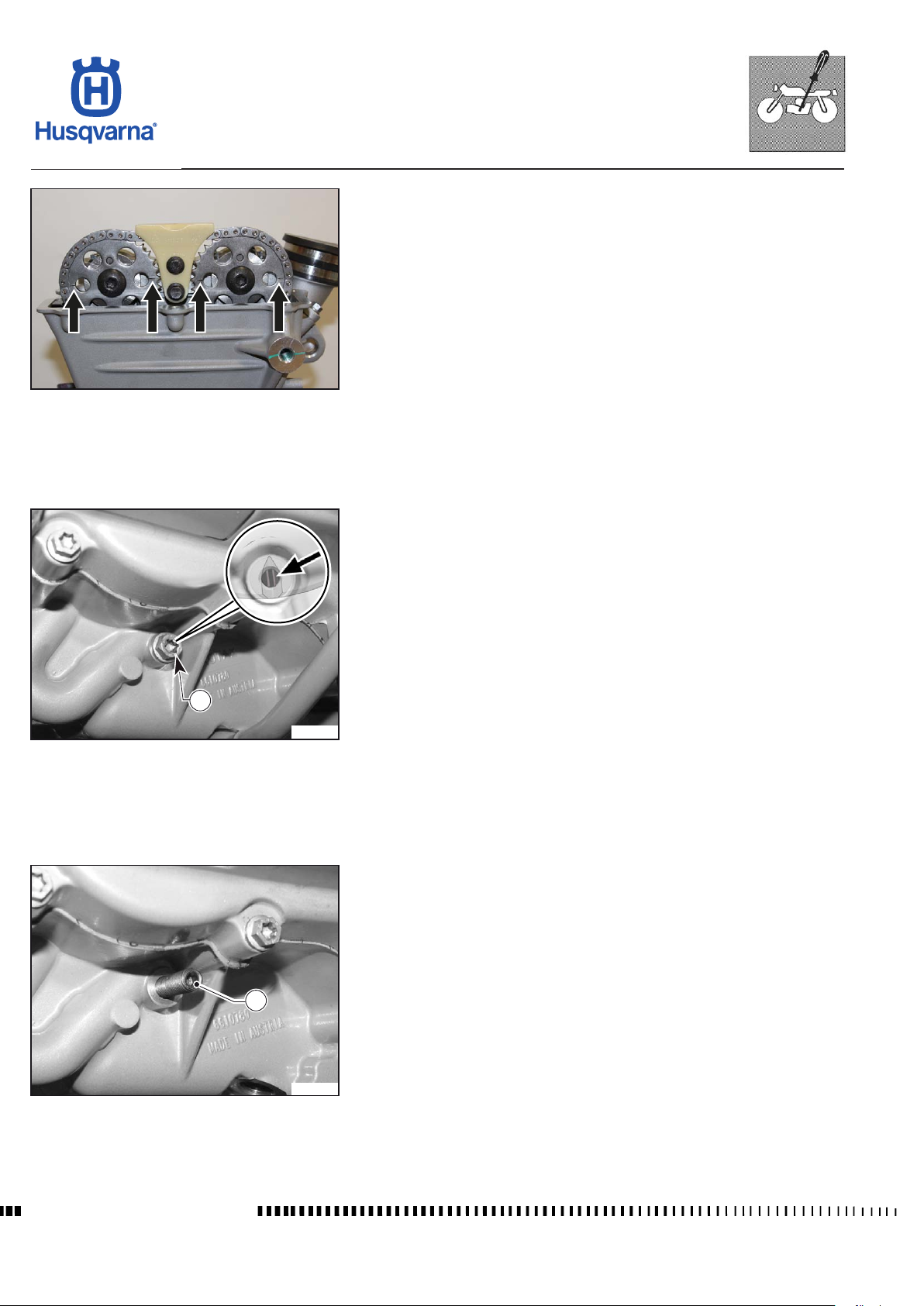
ENGINE SETTINGS AND ADJUSTMENTS
TR 650 TERRA 2013 - TR 650 STRADA 2013
PAD REPLACEMENT
Bring the to the top dead centre as described in the previous paragraph and
lock the crankshaft.
.
H11487
Locking the crankshaft
Remove the screw (1) with the sealing ring.
Check that the notch on the crankshaft is visible through the hole.
1
H11751
Fully screw down the retaining screw (2) manually; the screw must perfectly
engage in the notch of the crankshaft.
2
Workshop Manual Ed.09-2012
H11752
F.4
Page 97
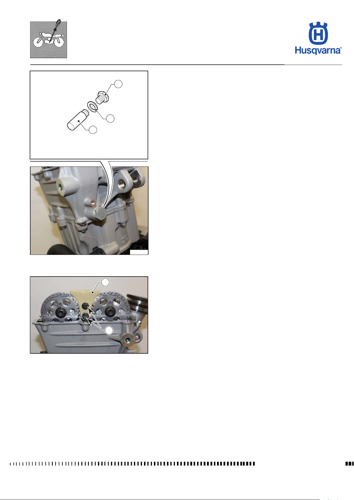
ENGINE SETTINGS AND ADJUSTMENTS
TR 650 TERRA 2013 - TR 650 STRADA 2013
Chain tensioner disassembly
1
2
3
H11491
- Remove the screw (1) with the sealing ring (2) and chain tensioner (3).
H11490
2
Chain guide disassembly
- Remove the screws (1) and chain guide (2).
1
H11492
F.5
Workshop Manual Ed.09-2012
Page 98
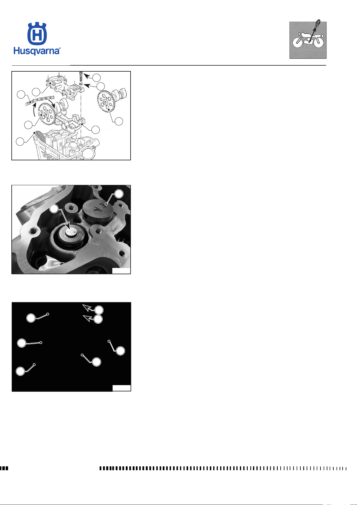
ENGINE SETTINGS AND ADJUSTMENTS
TR 650 TERRA 2013 - TR 650 STRADA 2013
1
2
3
4
5
5
Camshaft removal
- Remove the screws (1) with the washers.(2).
- Remove the top part of the support (3).
- Removethechain(4)fromthegearsandxtoapointsafetoavoiditfrom
falling into the engine.
- Remove the camshafts (5) with the chain gears.
- Remove the bottom part of the support (6).
- Remove the chain slider (7).
6
7
H11493
1
2
Pad replacement
- Mark the valve bucket (1) with a marker (e.g. A= intake valve).
- Extract the valve bucket (1)
- According to the measurement of the valve clearance, replace the pads with
those of a size appropriate to restore the correct valve clearance.
- Replace adjustment pad (2) with one having a thickness adequate to restore
thecorrectvalue,makingsureitisrmlyseatedintheseat.
- Install the corresponding valve buckets as marked.
3a
1
H11494
5
4
6
3b
2
H11495
Camshaft assembly
- Install the chain slider (1) making sure that the top part of the slider is aligned
with the sealing surface.
- Mount the bottom part of the support (2).
- Lubricate all contact surfaces with engine oil.
- Fit the camshaft exhaust (3a), then the cam shaft intake (3b) with the timing
chain and positioning them in phase.
- Mount the top part of the support (4).
- Tighten the screws (5) with the washers (6).
Workshop Manual Ed.09-2012
F.6
Page 99
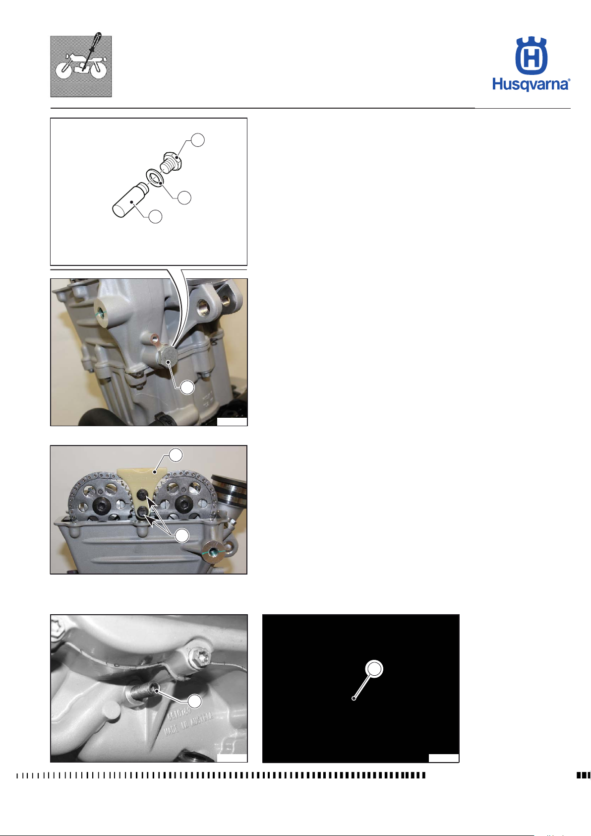
ENGINE SETTINGS AND ADJUSTMENTS
TR 650 TERRA 2013 - TR 650 STRADA 2013
Chain tensioner installation
2
3
1
H11496
- Insert the chain tensioner (1) and tighten the screw (2) replacing the gaskets
(3).
2
H11497
1
Chain guide installation
- Clean the threading and screws.
- Install the chain guide (1) and tighten the screws (2).
2
H11498
Removal of engine block screw
- Remove the locking screw (1) and re-tighten the screw (2) to torque, replacing the gasket.
2
1
H11499
F.7
H11646
Workshop Manual Ed.09-2012
Page 100
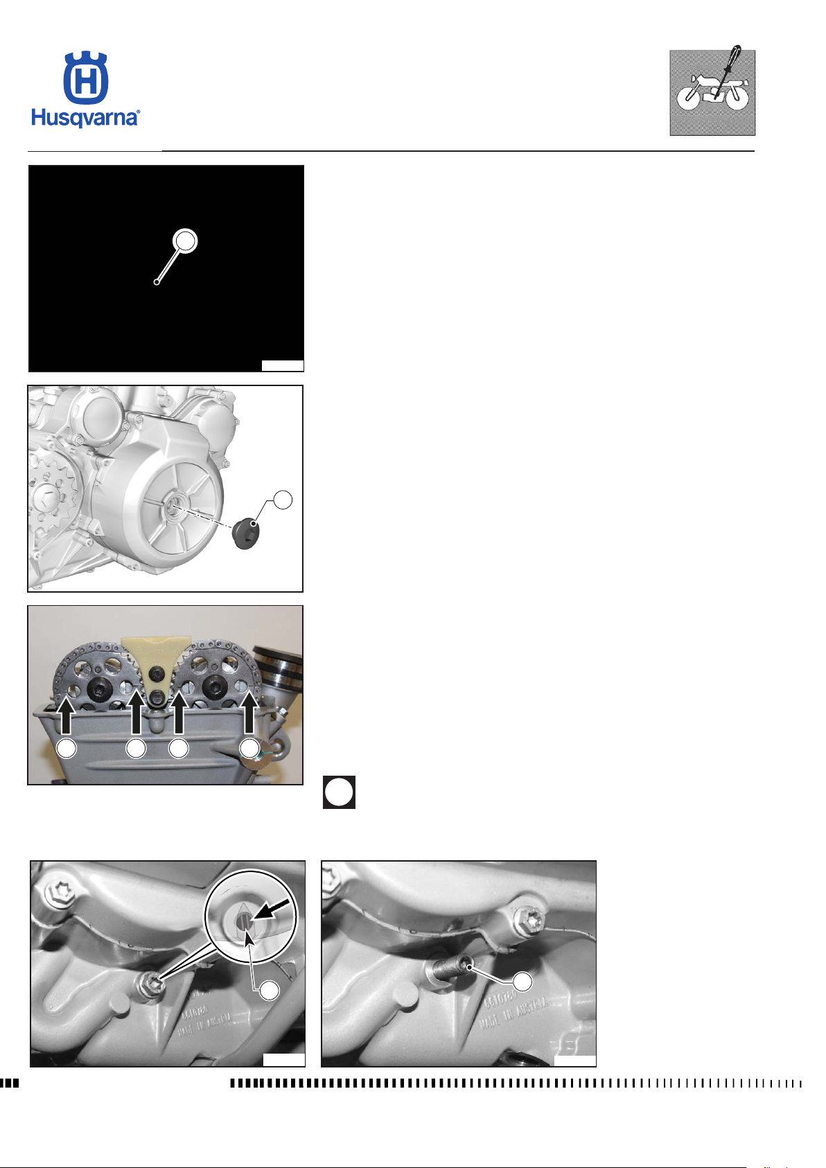
ENGINE SETTINGS AND ADJUSTMENTS
TR 650 TERRA 2013 - TR 650 STRADA 2013
TIMING CHECK
- Remove the coil / spark plug cap, head cover, spark plugs and chain tensioner
and the head cover as described in chapter "F1".
- Remove the screw (1) with the sealing ring.
1
H11488
- Remove the plug (2).
3 3 3 3
2
H11500
- Check the position of the camshaft gears.
- The marks (dashes) (3) located on the camshaft gears must be coplanar with
the sealing surface.
- Make sure the notch on the crankshaft is visible through the hole (marks (3)
coplanar to the surface and notch (4) visible indicate a correct timing).
- If the notch cannot be seen through the hole, carefully turn the engine until it
can be seen through the hole, then fully tighten down the retaining screw (5)
manually, blocking the engine at TDC; it must perfectly engage in the notch
of the crankshaft.
H11501
If the marks on the camshaft gears are not opposed and parallel to
the sealing surface, a collision between pistons and valves is possible.
Workshop Manual Ed.09-2012
4
H11502
5
H11503
F.8
 Loading...