

Page 1

TE 630 / 2011 I.E.
SMS 630 / 2011 I.E.
Part. N. 8000 H2051 (02-2010)
Workshop Manual
Page 2

HUSQVARNA MOTORCYCLES S.R.L. - Varese disclaims all liabilities
for any errors or omissions in this manual and reserves the right to make
changes to reect on-going product development. Illustrations in the manual may differ from actual components. No reproduction in full or in part
without written authorisation.
1st edition (02-2010)
Page 3
a.1Part. N. 8000 H2051 (02-2010)
1
FOREWORD, TABLE OF CONTENTS
1st edition (02-2010)
Printed in Italy
Print no. 8000 H2051
MODELS COVERED (from serial number onwards)
Copyright by
HUSQVARNA MOTORCYCLES S.R.L.
BMW Group
Technical Service
Via Nino Bixio, 8
21024
(Varese) - Italy
tel. ++39 0332 75.61.11
tel. ++39 0332 756 558
www.husqvarna-motorcycles.com
Workshop Manual
TE 630: ZKHA4 01AA B V 000001
TE 630 (USA): ZKHKD EKP# B V 000001
SMS 630: ZKHA4 01AB B V 000001
SMS 630 (USA): ZKHLD EKP# B V 000001
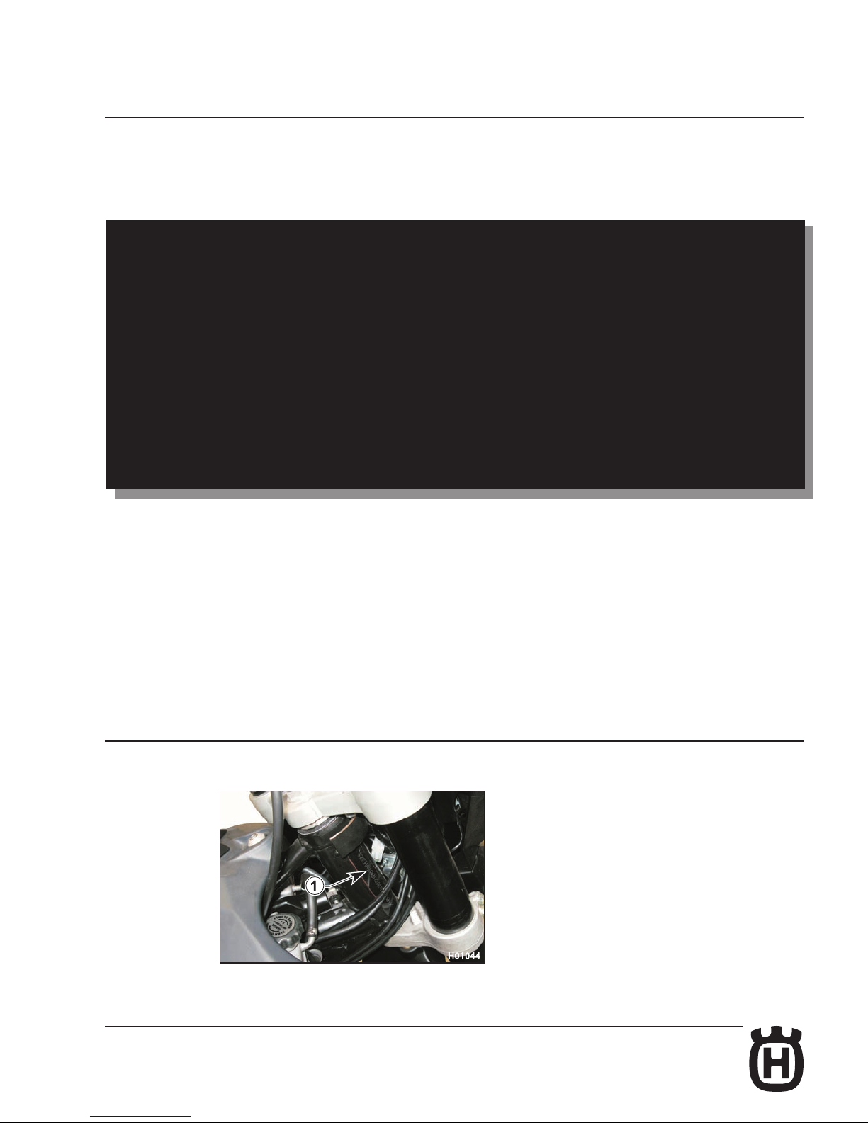
1. Chassis serial number
TE 630 / 2011 I.E.
SMS 630 / 2011 I.E.
Page 4
a.2 Part. N. 8000 H2051 (02-2010)
FOREWORD, TABLE OF CONTENTS
Foreword
This publication is designed for use by HUSQVARNA Service Centres to assist authorised personnel in the maintenance
and repair of the models covered in this manual. The technical information provided in this manual is a critical complement
to operator training and operators should become thoroughly familiar with it.
For ease of understanding, diagrams and photographs are provided next to the text.
Notes with special signicance are identied as follows throughout the manual:
Accident-prevention rules for operator and persons working nearby.
Damage to vehicle and/or its components may result from incompliance with relevant instructions.
Additional information concerning the operation covered in the text.
Useful tips
To prevent problems and ensure effective service work, observe the following HUSQVARNA recommendations:
– before repair, evaluate the customer's description of the problem and ask the appropriate questions to clearly identify
problem symptoms;
– diagnose the problem and identify the causes clearly. This manual provides basic background information that must
be supplemented with the operator's expertise and specic training available through HUSQVARNA held at regular
periods;
– plan ahead before starting work: gather any spare parts and tools to avoid unnecessary delays;
– avoid unnecessary disassembly work to get to the part that needs repairing.
Always read the relevant instructions and follow the disassembly sequence outlined in this manual.
Recommended shop practices
1 Always replace gaskets, sealing rings and split pins with new ones.
2 When loosening or tightening nuts or bolts, always begin with the bigger ones or from the centre. Tighten to the spe-
cied torque and follow a cross pattern.
3 Always mark any parts or positions that might be confused upon assembly.
4 Use genuine HUSQVARNA parts and the recommended lubricant brands.
5 Use special tools where specied.
6 Technical Bulletins might contain more up-to-date setting data and procedures than this manual. Be sure to read
them.
IMPORTANT: Where not specied, reassembled components must be tightened to the proper torque as indicated
in the tables provided in Chapter "x".
Page 5

a.3Part. N. 8000 H2051 (02-2010)
FOREWORD, TABLE OF CONTENTS
Table of Contents
Title Section
Foreword, Table of Contents ............................................................................... a
Important Notices ................................................................................................b
General Information .............................................................................................A
Maintenance ........................................................................................................B
Troubleshooting .................................................................................................. C
Settings and Adjustments ................................................................................... D
General Procedures ............................................................................................E
Engine Disassembly ............................................................................................ F
Engine Overhaul ................................................................................................. G
Engine Reassembly............................................................................................ H
Front Suspension .................................................................................................I
Rear Suspension ................................................................................................. J
Brakes .................................................................................................................L
Electrical System ................................................................................................ M
Engine Cooling ................................................................................................... N
Hydraulically Controlled Clutch............................................................................P
Optional Components ......................................................................................... Q
Fuel Injection System ..........................................................................................S
Special Tools ......................................................................................................W
Tightening Torque Figures ...................................................................................X
Chassis and Wheels ............................................................................................Y
NOTES
Unless otherwise specied, data and specications apply to all models.
Page 6

Page 7
b.1Part. N. 8000 H2051 (02-2010)
b
IMPORTANT NOTICES
Section
Page 8
b.2 Part. N. 8000 H2051 (02-2010)
TE
SMS
IMPORTANT NOTICES
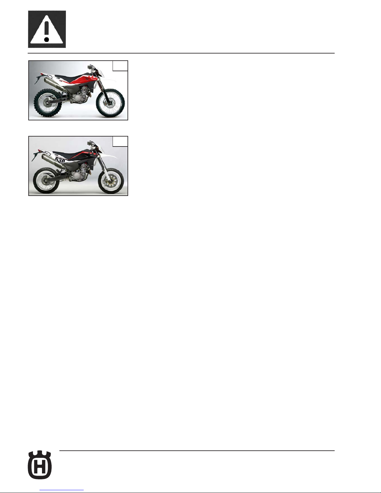
TE and SMS models are STREET LEGAL motorcycles; they are guaranteed
exempt from functional defects and covered with legal guarantee, as far as the
STANDARD CONFIGURATION IS MAINTAINED and the suggested maintenance
table shown in Section "B" is observed.
IMPORTANT
VEHICLE CONFIGURATION as outlined below is a prerequisite for the warranty
to remain valid:
A) STANDARD MOTORCYCLE, FOR ROAD USE.
* In order to maintain the vehicle’s “Guarantee of Functionality”, the client must
follow the maintenance programme indicated in Section B by having the required
maintenance inspections carried out at authorised HUSQVARNA dealers. The
cost for changing parts and for the labour necessary in order to comply with
the maintenance plan is charged to the Client. The warranty becomes NULL
AND VOID if the motorcycle is rented.
Notes
Left and right side is determined when seated on motorcycle.
Z: number of teeth
A: Austria
AUS: Australia
B: Belgium
BR: Brazil
CDN: Canada
CH: Switzerland
D: Germany
E: Spain
F: France
FIN: Finland
GB: Great Britain
I: Italy
J: Japan
USA: United States of America
Unless otherwise specied, data and instructions apply to all market variants.
Page 9
A.1Part. N. 8000 H2051 (02-2010)
A
GENERAL INFORMATION
Section
Page 10
A.2 Part. N. 8000 H2051 (02-2010)
GENERAL INFORMATION
Engine ..........................................................................................................A.3
Timing system ..............................................................................................A.3
Fuel system ..................................................................................................A.3
Lubrication ....................................................................................................A.3
Cooling .........................................................................................................A.3
Ignition system..............................................................................................A.3
Starter ..........................................................................................................A.3
Drive and Transmission ................................................................................A.3
Chassis .........................................................................................................A.4
Suspension ...................................................................................................A.4
Brakes ..........................................................................................................A.4
Wheels..........................................................................................................A.4
Tyres .............................................................................................................A.5
Electrical components location .....................................................................A.5
Overall dimensions - Weight .........................................................................A.6
Capacities .....................................................................................................A.7
Page 11
A.3Part. N. 8000 H2051 (02-2010)
GENERAL INFORMATION
Engine
Type .............................................................................. single cylinder, 4 stroke
Cooling ............................................ Liquid with double radiator and heater fan
Bore .......................................................................................................100 mm
Stroke ...................................................................................................76.4 mm
Displacement ..................................................................................... 600 cu.cm
Compression ratio ...................................................................................12.4:1
Starting .................................................................................................. electric
Timing system
Type .................................double overhead camshaft chain operated; 4 valve
Valve clearance ( cold with engine)
Intake .........................................................................................0.10 ÷ 0.15 mm
Exhaust......................................................................................0.15 ÷ 0.20 mm
Fuel system
Type ..............................................................................Electronic injection feed
Air cleaning: dry air lter
Lubrication
Type .................Dry sump with positive displacement pump and cartridge lter
Cooling
Liquid with double radiator and electric fan
Coolant capacity .................................................................................. 1.2 Litres
Ignition system
Type ....................................................................................Electronic, inductive
with adjustable advance (digital control)
Spark plug type..............................................................................NGK CR8EB
Spark plug gap ............................................................................. 0.7 - 0.8 mm
Drive and transmission
Clutch: oil bath multiple disc clutch, hydraulic control
Transmission: constant mesh gear type
Motion is transmitted from engine to gearbox primary shaft through spur gears
Primary drive
Drive pinion gear .........................................................................................Z 32
Clutch ring gear ..........................................................................................Z 75
Transmission ratio .................................................................................... 2.343
Gear ratios:
Type .............................................................................constant mesh gear type
Transmission ratio
(TE)
1st gear.......................................................................................2.615 (z 34/13)
2nd gear .....................................................................................1.812 (z 29/16)
3rd gear ......................................................................................1.350 (z 27/20)
4th gear ......................................................................................1.091 (z 24/22)
5th gear ......................................................................................0.916 (z 22/24)
6th gear ......................................................................................0.769 (z 20/26)
FINAL RATIOS (SMS)
1st gear.......................................................................................2.615 (z 34/13)
2nd gear .....................................................................................1.812 (z 29/16)
3rd gear ......................................................................................1.350 (z 27/20)
4th gear ......................................................................................1.091 (z 24/22)
5th gear ......................................................................................0.957 (z 22/23)
6th gear ......................................................................................0.880 (z 22/25)
Page 12
A.4 Part. N. 8000 H2051 (02-2010)
GENERAL INFORMATION
Secondary drive
Motion is transmitted from gearbox to rear wheel by 5/8" x 1/4" nal drive chain ("D.I.D." 520 DS or "REGINA" 135 RX3)
Transmission sprocket ................................................................................Z 15
Rear wheel sprocket (TE) ............................................................................Z 42
Rear wheel sprocket (SMS)......................................................................... Z 38
Transmission ratio (TE) ............................................................................. 2.800
Transmission ratio (SMS) .......................................................................... 2.533
Transmission chain dimensions ...........................................................5/8”x1/4”
Final ratios
(TE)
1st gear.................................................................................................... 17.163
2nd gear .................................................................................................. 11.894
3rd gear ..................................................................................................... 8.859
4th gear .....................................................................................................7.159
5th gear .....................................................................................................6.016
6th gear .....................................................................................................5.048
(SMS)
1st gear.................................................................................................... 15.529
2nd gear ..................................................................................................10.762
3rd gear ..................................................................................................... 8.016
4th gear .....................................................................................................6.477
5th gear .....................................................................................................5.679
6th gear .....................................................................................................5.225
Chassis
Type .................single frame, in circular sectioned tubes, in steel; rear chassis in squared sectioned tubes in light alloy.
Suspension
Front
Type “Upside-down” telescopic hydraulic front fork with advanced axle (adjustable in rebound stroke); tubes ø 45 mm
Leg axis stroke (TE) .............................................................................. 270 mm
Leg axis stroke (SMS) ........................................................................... 250 mm
Rear
Type .................progressive with hydraulic single shock absorber
(preload regulation of spring and hydraulic brake in compression and extension)
Wheel stroke (TE).................................................................................. 320 mm
Wheel stroke (SMS) .............................................................................. 290 mm
Brakes
Front
Type (TE) .......................................................................... xed disc Ø 260 mm
with hydraulic control and oating calliper
Type (SMS).................................................................... oating disk Ø 320 mm
with hydraulic command and radial xed calliper
Rear
Type ................. xed disc Ø 220 mm with hydraulic control and oating calliper
Wheels
Rims
Front (TE) ......................................................................... in light alloy: 1.6”x21”
Front (SMS) .................................................................... in light alloy: 3.50”x17”
Rear (TE) ........................................................................ in light alloy: 2.15”x18”
Rear (SMS) ..................................................................... in light alloy: 4.25”x17”
Page 13
A.5Part. N. 8000 H2051 (02-2010)
GENERAL INFORMATION
Tyres
Front
(TE) ..................................................................................................... 90/90x21”
(SMS) ...............................................................................................120/70x17”
Rear
(TE) ................................................................................................... 140/80x18”
(SMS) ...............................................................................................150/60x17”
Cold tyre pressure (TE)
Front
Rider only ..........................................................................................1.2 Kg/cm
2
Rider and passenger ........................................................................1.5 Kg/cm
2
Rear
Rider only ..........................................................................................1.5 Kg/cm
2
Rider and passenger ........................................................................1.8 Kg/cm
2
Cold tyre pressure (SMS)
Front
Rider only ..........................................................................................1.8 Kg/cm
2
Rider and passenger .........................................................................2.0 Kg/cm
2
Rear
Rider only ..........................................................................................2.0 Kg/cm
2
Rider and passenger .........................................................................2.2 Kg/cm
2
ELECTRICAL COMPONENTS LOCATION
The ignition system includes the following elements:
- Generator on the inner side of L.H. crankcase half cover;
- Electronic ignition coil under the fuel tank;
- Electronic control unit under the saddle;
- Voltage regulator on the R.H. side of the rear chassis;
- Spark plug on the R.H. side of the cylinder head;
- 12V-700W starter motor behind the engine cylinder;
- Solenoid starter located on the fuse holder plate, under the saddle;
- M.A.Q.S. sensor (pressure, throttle position, air temperature) on throttle body.
The electrical system includes the following elements:
- 12V-14Ah battery under the saddle;
- Turning indicators asher located on the utilities holder plate, under the saddle;
- Relays located on the utilities holder plate, under the saddle;
- Electric fan relay;
- Injector, Lambda sensor, fuel pump, coil relay;
- Horn, turning indicators, stop lights, low and high beam lights relay;
- Electric fan;
- Fuses located on the utilities holder plate, under the saddle;
- Fuse FP- 15A (cable sheath marked “P”): fuel pump, HT coil, lambda sensor heater, injector;
- Fuse FM- 15A (cable sheath marked “M”): 12V depending on ignition switch, (system voltage), parking lights;
- Fuse FDC- 20A (cable sheath marked “DC”): electric fan, rear stop light, high beam, low beam, turning indicators, horn, instrument panel power supply (instrument functions display).
- Rollover sensor (SMS) located on the utilities holder plate, under the saddle;
- Coolant temperature sensor;
- Lambda sensor;
- Headlamp with 12V-60/55W twin halogen bulb and 12V-5W parking light bulb;
- LED tail light;
- 12V-10W turning indicator bulbs;
- Fuel pump inside the fuel tank.
Page 14
A.6 Part. N. 8000 H2051 (02-2010)
GENERAL INFORMATION
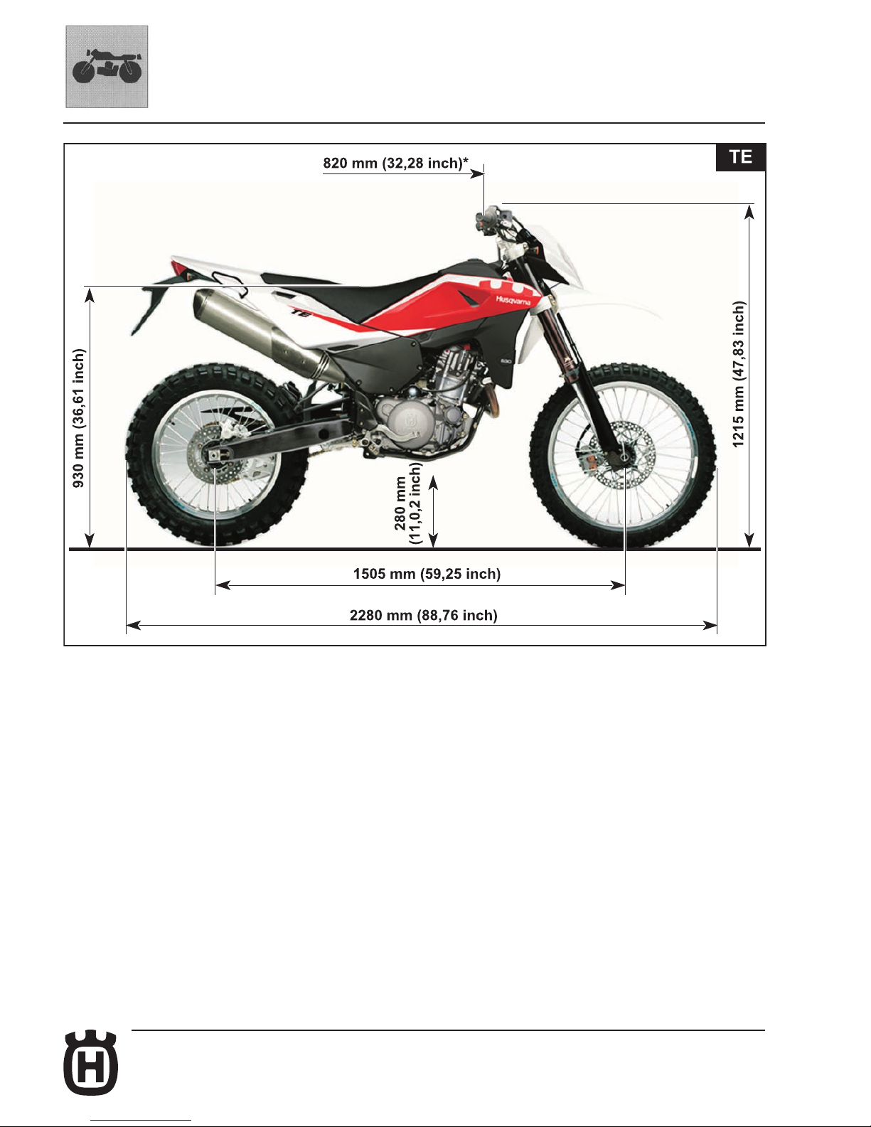
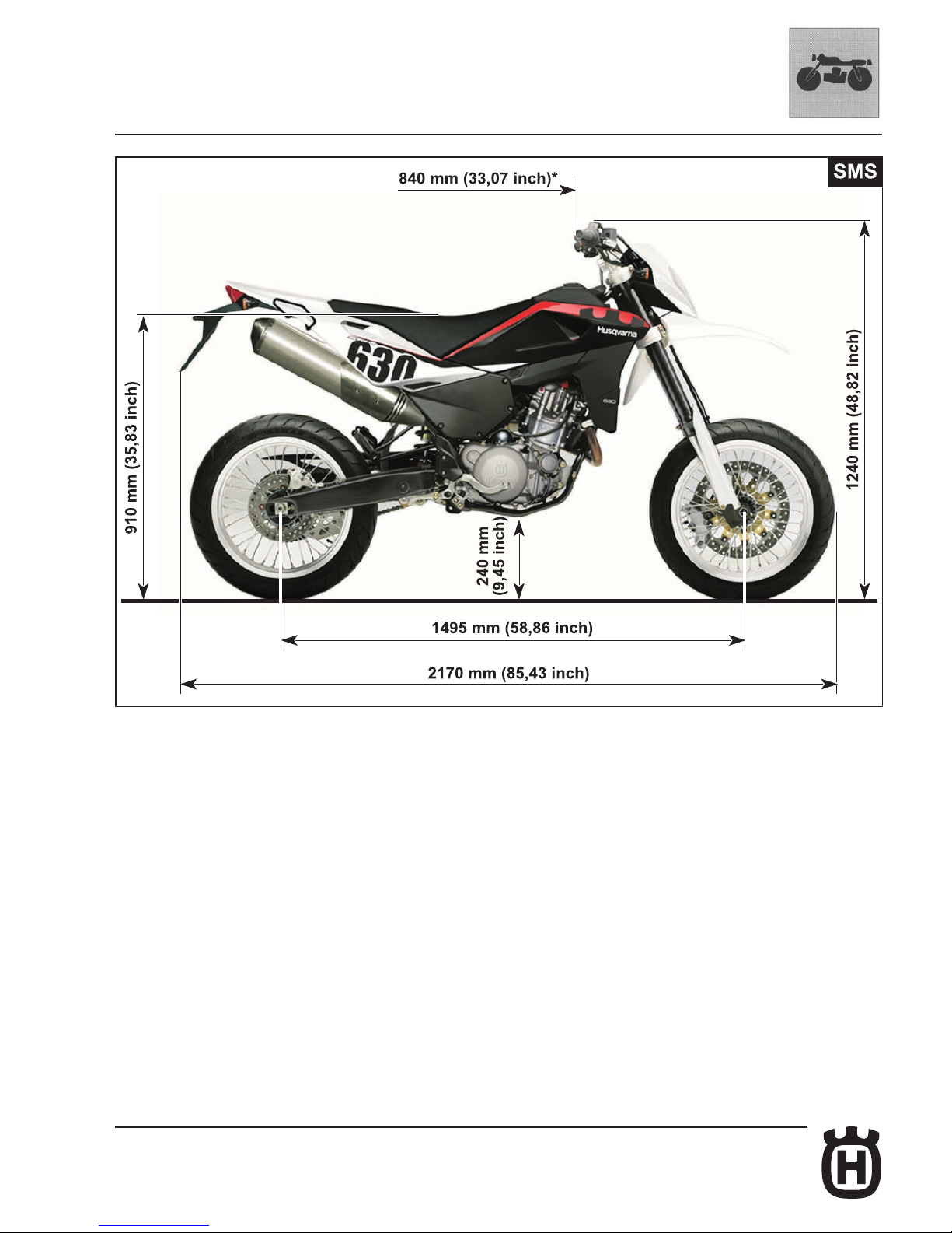
Overall dimensions - Weight
Kerb weight, without fuel
(TE): .......................................................................................150 Kg (330.69 lb)
(SMS): ...................................................................................158 Kg (348.33 lb)
*: max. width
Page 15
A.7Part. N. 8000 H2051 (02-2010)
GENERAL INFORMATION
Page 16
A.8 Part. N. 8000 H2051 (02-2010)
GENERAL INFORMATION
Capacities Type Quantity
Fuel tank including reserve 98 octane unleaded fuel 12 litres (3.17 GAL)
Reserve fuel (warning light goes on) 2.5 litres (0.66 GAL)
Gearbox/engine oil CASTROL POWER 1 RACING 10W-50 2 litres (0.53 GAL)
(oil change and oil lter
replacement)
Gearbox/engine oil CASTROL POWER 1 RACING 10W-50 1.8 litres (0.48 GAL)
(oil change)
Front fork oil CASTROL SYNTHETIC FORK OIL 5W 610 cc (37.22 CU IN)
Rear shock absorber oil CASTROL SYNTHETIC FORK OIL 5W
Coolant CASTROL MOTORCYCLE COOLANT 1.2 litres (0.27 GAL)
Brake system uid CASTROL RESPONSE SUPER DOT 4
Clutch uid CASTROL FORK OIL 10W
Secondary drive chain lubrication CASTROL CHAIN LUBE RACING
Grease lubrication CASTROL LM GREASE 2
Electric contact protection CASTROL METAL PARTS CLEANER
Fillers for radiator AREXONS LIQUID FILLER
Air lter oil CASTROL FOAMAIR FILTER OIL
Air lter cleaner CASTROL FOAMAIR FILTER CLEANER
IMPORTANT - Do not add any additives to fuel or lubricants.
Page 17
B.1Part. N. 8000 H2051 (02-2010)
B
MAINTENANCE
Section
Page 18
B.2
Part. N. 8000 H2051 (02-2010)
MAINTENANCE
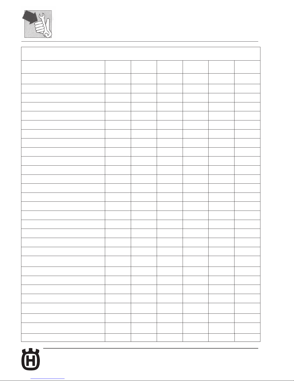
SCHEDULED MAINTENANCE CHART
(TO BE CARRIED OUT AT THE HUSQVARNA DEALER)
TE - SMS
- STANDARD MOTORCYCLE, FOR ROAD USE
(DERATED)
AFTER FIRST
1000 KM
AFTER FIRST
5000 KM
AFTER FIRST
10000 KM
AFTER FIRST
15000 KM
AFTER FIRST
20000 KM
REPLACE
AS
REQUIRED
PART
SERVICE
COUPON
SERVICE
COUPON
SERVICE
COUPON
SERVICE
COUPON
SERVICE
COUPON
VALVES
C (*) C (*) C (*) C (*) C (*)
INTAKE/EXHAUST ROCKER ARMS
C C
TIMING CHAIN
S
TIMING CHAIN SLIDER
S
TIMING DRIVEN GEAR
S
SPARK PLUG
P S P S
SPARK PLUG CAP
C C C C
ENGINE OIL
S S S S S
ENGINE OIL INTAKE FILTER
P P P
CLUTCH CUSH DRIVE DAMPER
C C
ENGINE OIL FILTER CARTRIDGE
S S S
AIR FILTER
P P/S (**) S P/S (**) S
CLUTCH AND BRAKE FLUIDS
C C S C S
BRAKE HYDRAULIC CONTROLS
C C C C C
BRAKE PADS WEAR
C C S
BOWDEN CABLES
C P P P P
THROTTLE CONTROL
C C C C C
TYRE PRESSURE AND WEAR
C C C C C
ELECTRIC FAN
C C C C
HEADLAMP BEAM
HEIGHT
C
LIGHTS/INDICATIONS/HORN
C C C C C
BATTERY
C C C C
WHEEL SPOKES TENSION
C C C C C C
STEERING BEARINGS PLAY
C C C
SECONDARY DRIVE CHAIN/TENSIONER
ROLLERS
CL CL S CL S
CHAIN
CL CL S CL S
SIDE STAND SCREWS
C
C
C
C
C
REAR CHAIN SPROCKET/TRANSMISSION
SPROCKET
C S C S
Page 19
B.3Part. N. 8000 H2051 (02-2010)
MAINTENANCE
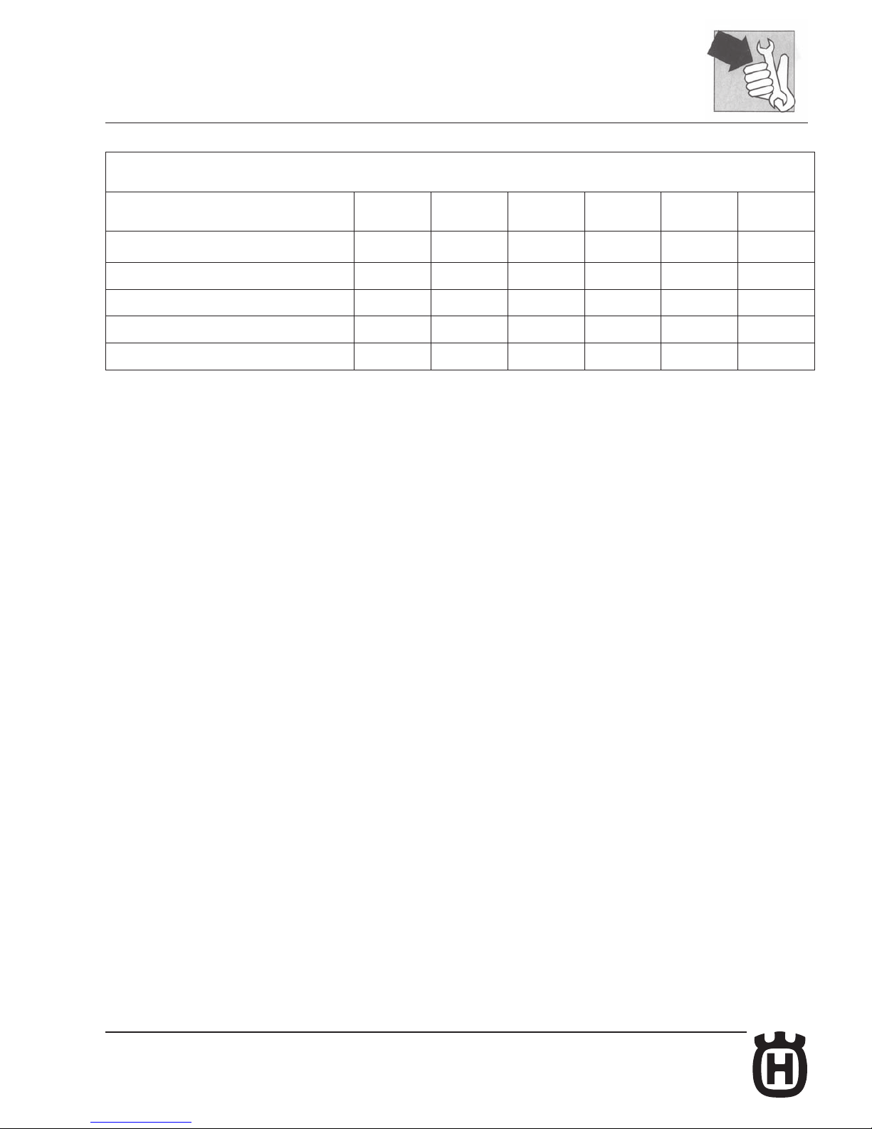
SCHEDULED MAINTENANCE CHART
(TO BE CARRIED OUT AT THE HUSQVARNA DEALER)
TE - SMS
- STANDARD MOTORCYCLE, FOR ROAD USE
(DERATED)
AFTER FIRST
1000 KM
AFTER FIRST
5000 KM
AFTER FIRST
10000 KM
AFTER FIRST
15000 KM
AFTER FIRST
20000 KM
REPLACE
AS
REQUIRED
PART
SERVICE
COUPON
SERVICE
COUPON
SERVICE
COUPON
SERVICE
COUPON
SERVICE
COUPON
WHEEL HUB BEARINGS
C C
FRONT FORK OIL
S/R S/R
OVERALL TIGHTENING OF NUTS AND BOLTS
C C C C C
LUBRICATION/GREASING
L L L L L
LEGEND
C: CHECK
C (*): CHECK CLEARANCE
P: CLEAN
P/S (**): CLEAN OR CHANGE (depending on the conditions of use of the motorcycle)
S: REPLACE
L: LUBRICATION
R: FORK OVERHAUL
NOTES:
- REPLACE GASKETS AND SEALS AFTER EACH REMOVAL;
- REPLACE SCREWS AND BOLTS IF DAMAGED;
- PERFORM A GENERAL INSPECTION AFTER RIDING ON MUDDY OR SANDY TERRAIN.
Page 20

Page 21
C.1Part. N. 8000 H2051 (02-2010)
C
TROUBLESHOOTING
Section
Page 22
C.2 Part. N. 8000 H2051 (02-2010)
TROUBLESHOOTING
ENGINE
Trouble Cause Remedy
Engine does not start or Insufcient compression
it hardly starts 1. Piston seizure Replace
2. Connecting rod small or big end seized Replace
3. Worn piston rings Replace
4. Worn cylinder Replace
5. Cylinder head loosely tightened Tighten
6. Head gasket leaking Replace
7. Spark plug loose Tighten
8. Incorrect valve clearances Adjust
9. Weak or seized valve springs Replace
10. Seized valves Replace
Weak or no spark
1. Spark plug faulty Replace
2. Fouled or wet spark plug Clean or dry
3. Spark plug electrode gap too wide Adjust
4. Ignition coil faulty Replace
5. High-tension cables open circuit or shorted Check
6. Electronic control unit faulty Replace
7. Right-hand switchfaulty Replace
The engine stops 1. Dirty spark plug Clean
easily 2. Electronic control unit faulty Replace
3. Low idle Adjust
Engine is noisy Noise seems to come from piston
1. Too much piston-to-cylinder clearance Replace
2. Worn piston rings or piston grooves Replace
3. Too much carbon build-up in
combustion chamber or on piston crown Clean
4. Worn drop link Replace
5. Valve clearances too large Adjust
6. Weak or seized valve springs Replace
7. Worn timing chain Replace
8. Incorrect timing chain tension Adjust
Noise seems to come from crankshaft
1. Worn main bearings Replace
2. Connecting rod big end has too much side
clearanceorendoat Replace
3. Crankshaft gear damaged Replace
4. Crankshaft locknut loose Tighten
Page 23
C.3Part. N. 8000 H2051 (02-2010)
TROUBLESHOOTING
Trouble Cause Remedy
Noise seems to come from the clutch
1. Worn plates Replace
2. Too much clearance between clutch housing
and friction plates Replace
Noise seems to come from gearbox
1. Worn gears Replace
2. Worn gear grooves Replace
The noise seems to come 1. Chain stretched or incorrectly adjusted Replace or adjust
from the secondary 2. Worn transmission sprockets Replace
transmission chain
The clutch slides 1. Clutchadjusterscrewwithinsufcientclearance Adjust
2. Weak clutch springs Replace
3. Worn clutch plates Replace
The clutch is tight 1. Clutch adjuster screw with exceeding clearance Adjust
2. Non uniform spring load Replace
3. Bent clutch plates Replace
The gears cannot be inserted 1. Bent or seized gearbox forks Replace
2. Worn gear ratchets Replace
3. Damaged shifter fork shafts Replace
Gear shift pedal
does not return in position 1. Weak or broken selector return spring Replace
2. Worn shifter forks Replace
The gears are disengaged 1. Worn sliding gear engagements Replace
2. Worn gear grooves Replace
3. Worn dog slots in gears Replace
4. Worn selector shaft splines Replace
5. Damaged shifter fork shafts Replace
Engine power lack 1. Dirtyairlter Clean
2. Poor fuel quality Replace
3. Intake coupling loose Tighten
4. Spark plug electrode gap too wide Adjust
5. Insufcientcompression Identifycause
6. Incorrect valve clearance Adjust
7. Valve seats or guides faulty Replace
8. Weak or seized valve springs Replace
The engine overheats 1. Dirty combustion chamber and/or piston crown
with carbon deposits Clean
2. Insufcientoilinengineor
wrong oil Top up or change
3. Obstructionsblockingairowonradiator Clean
4. Cylinder head gasket leaking Replace
5. Clutch slips Adjust
6. Cooling fan faulty Replace thermal switch
Page 24
C.4 Part. N. 8000 H2051 (02-2010)
TROUBLESHOOTING
CHASSIS
Trouble Cause Remedy
The handlebar is hard to turn 1. Tyrepressureinsufcient Inate
2. Bearing adjuster ring nut or steering stem nut overtightened Adjust
3. Bent steering stem Replace bottom yoke
4. Worn or seized steering bearings Replace
The handlebar vibrates 1. Bent fork legs Replace
2. Bent front wheel axle Replace
3. Warped chassis Replace
4. Bent front wheel rim Replace
5. Worn front wheel bearings Replace
Shock absorption is 1. Exceeding oil quantity in fork legs Drain the exceeding oil
too hard 2. Fork oil viscosity too high Change
3. Overinatedtyres Deate
4. Improperly set rear shock absorber Adjust
Shock absorption is 1. Insufcientoilquantityinforklegs Topup
too soft 2. Fork oil viscosity too low Change
3. Weak fork springs Replace
4. Weak rear shock absorber spring Replace
5. Improperly set rear shock absorber Adjust
Wheel (front and 1. Bent wheel rim Replace
rear) vibrates 2. Worn wheel hub bearings Replace
3. Incorrect spoke tension Adjust
4. Wheel axle nut loose Tighten
5. Worn rear swinging arm bearings Replace
6. Improperly adjusted chain tensioners Adjust
7. Improperly balanced wheel Balance
Rear suspension is 1. Worn spacers or connecting rod bearings Replace
noisy 2. Worn shock absorber ball joints Replace
3. Shock absorber faulty Replace
Insufcient breaking 1. Air presence in braking system circuit Bleed
(front and rear) 2. Insufcientuidintank Topup
3. Worn brake pad and/or disc Replace
4. Damaged disc Replace
5. Improperly adjusted brake pedal Adjust
6. Waterinbrakesystem Changeuid
Page 25
C.5Part. N. 8000 H2051 (02-2010)
TROUBLESHOOTING
ELECTRICAL SYSTEM (see also Section M)
Trouble Cause Remedy
The spark plug gets dirty 1. Mixture too rich Adjust carburettor
easily 2. Dirtyairlter Clean
3. Worn piston rings Replace
4. Worn piston or cylinder liner Replace
Spark plug electrodes 1. Mixture too lean Adjust carburettor
overheat 2. Spark plug electrode gap too close Adjust
3. Heat rating too high Replace with recommended
spark plug
Generator does not provide charge
1. Cable arriving to the voltage regulator badly connected Connect correctly or
or is not providing enough charge
shorted replace
2. Voltage regulator faulty Replace
3. Generator coil faulty Replace
Overload generator 1. Voltage regulator faulty Replace
Battery does not hold charge 1. Battery terminals dirty Clean
Starter motor 1. Batteryisat Charge
does not start or slips 2. Control on R.H. switch faulty Replace
3. Starter relay faulty Replace
4. Starter motor faulty Repair or replace
5. Worn starter gears Replace
6. Worn or damaged freewheel rollers Replace freewheel
FUEL INJECTION SYSTEM (See Section S)
Page 26

Page 27
D.1Part. N. 8000 H2051 (02-2010)
D
SETTINGS AND ADJUSTMENTS
Section
Page 28
D.2 Part. N. 8000 H2051 (02-2010)
SETTINGS AND ADJUSTMENTS
Saddle removal.............................................................................................D.4
Tank removal ................................................................................................D.4
Tank removal ................................................................................................D.5
Tank disassembly .........................................................................................D.8
Valve clearance adjustment ........................................................................D.10
Throttle cable adjustment ...........................................................................D.11
Enrichener lever play adjustment ...............................................................D.11
Idle adjustment ...........................................................................................D.12
Engine oil level check .................................................................................D.12
Engine oil replacement, oil lter replacement .............................................D.13
Mesh lters cleaning ...................................................................................D.14
Coolant level check ....................................................................................D.16
Coolant replacement ..................................................................................D.17
Clutch plate replacement ............................................................................D.18
Clutch disassembly.....................................................................................D.18
Hydraulic clutch lever adjustment and uid level check ............................D.19
Front brake lever adjustment and uid level check ....................................D.20
Rear brake pedal adjustment .....................................................................D.21
Rear brake pedal free play adjustment.......................................................D.21
Rear brake uid level check .......................................................................D.22
Air lter check .............................................................................................D.22
Air lter cleaning .........................................................................................D.23
Chain adjustment .......................................................................................D.24
Chain lubrication .........................................................................................D.25
Removal and cleaning ................................................................................D.25
Washing a chain without O-rings ................................................................D.25
Chain guide roller, chain guide eye, chain slider ......................................D.25
Lubricating an O-ring chain ........................................................................D.25
Suspension .................................................................................................D.26
Rear shock absorber adjustment................................................................D.27
Shock absorber spring preload adjustment ................................................D.28
Shock absorber compression and rebound damping adjustment ..............D.29
MARZOCCHI front fork adjustment ............................................................D.30
Fork oil level ...............................................................................................D.31
MARZOCCHI front fork springs ..................................................................D.32
Steering bearing clearance adjustment ......................................................D.33
Supply hose check .....................................................................................D.34
Exhaust system check ................................................................................D.35
Page 29
D.3Part. N. 8000 H2051 (02-2010)
SETTINGS AND ADJUSTMENTS
Page 30
D.4 Part. N. 8000 H2051 (02-2010)
SETTINGS AND ADJUSTMENTS
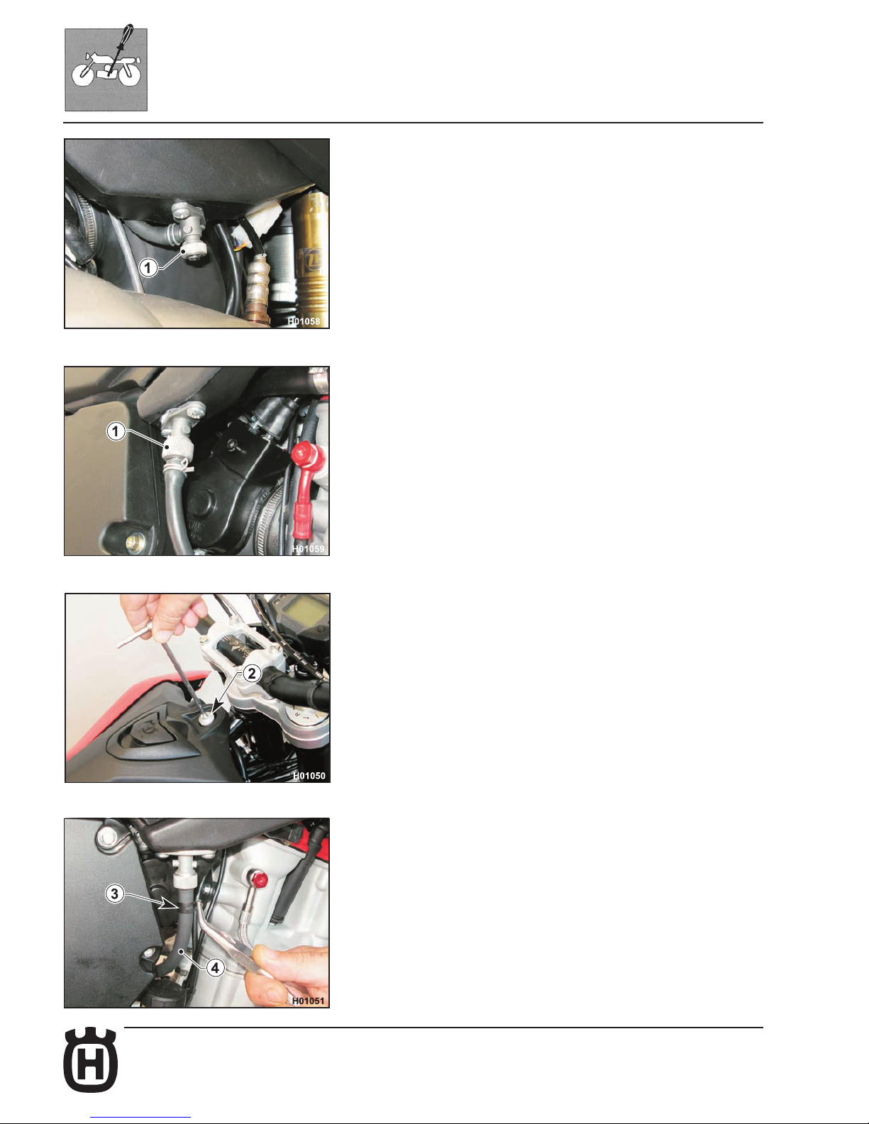
Tank removal
Remove the saddle as described in the relevant paragraph.
Close both fuel cocks (1).
Use a 6 mm Allen wrench to loosen the screw (2) and remove the
screw with its spacer.
Place a vessel under the R.H. cock to collect fuel.
Loosen clamp (3) and disconnect tube (4) from the fuel cock. Let the
fuel drain out.
Page 31
D.5Part. N. 8000 H2051 (02-2010)
SETTINGS AND ADJUSTMENTS
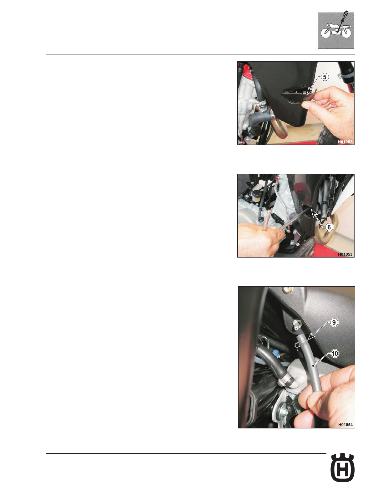
Remove the covers (5) located on the R.H. and L.H. side of the tank.
Loosen the screws (6) using an 8 mm wrench.
Move to the left side of the tank, slacken clamp (9) and disconnect the
breather hose (10).
Page 32
D.6 Part. N. 8000 H2051 (02-2010)
SETTINGS AND ADJUSTMENTS
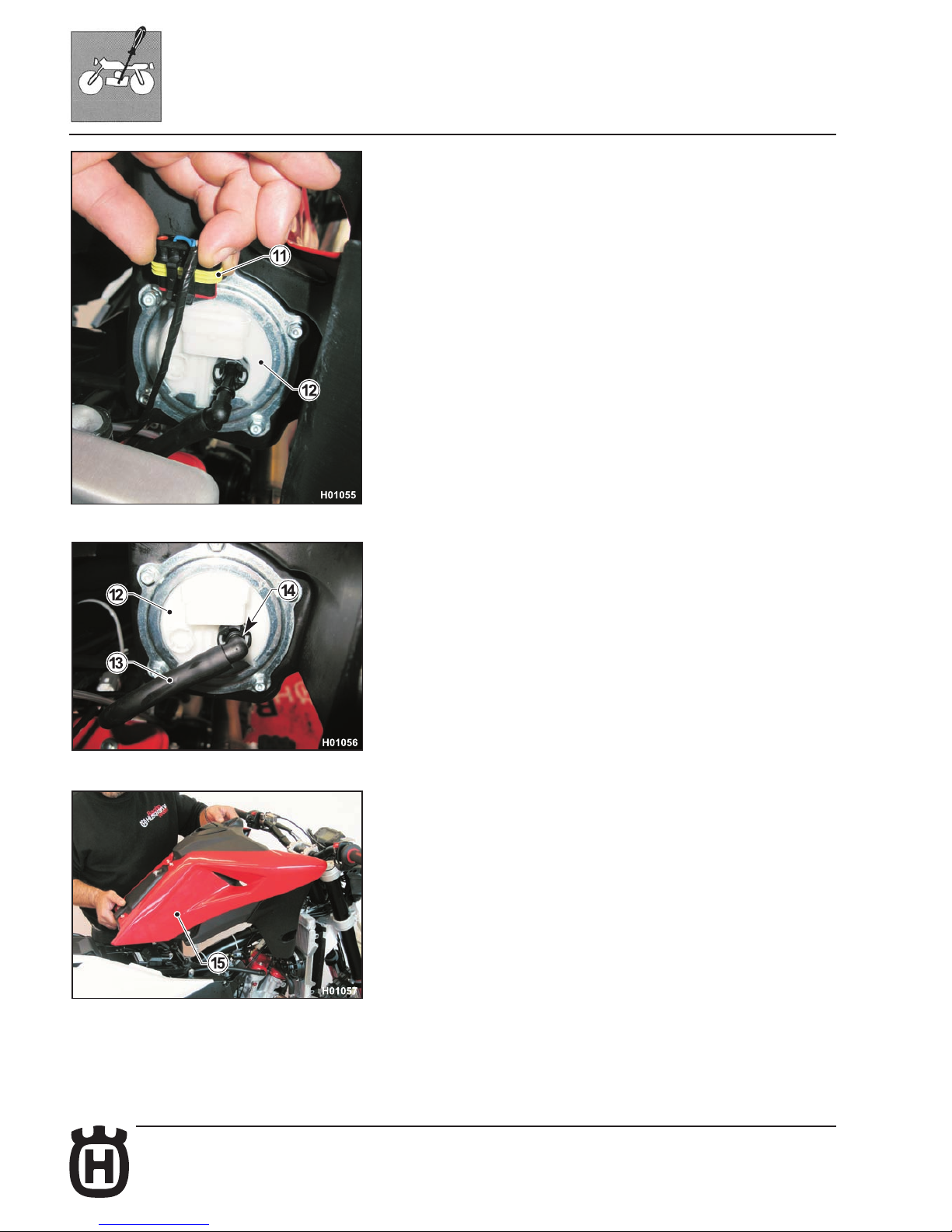
Raise the tank from the front end and disconnect the fuel pump (12)
connector (11).
Disconnect the hose (13) connecting tank to throttle body; press down
the ring (14) and disconnect hose (13) from pump (12).
Raise the tank (15) and remove it together with the scoops.
Reassemble all parts in the reverse order compared to disassembly
and tighten screws to the specied torque (see Section X).
Page 33
D.7Part. N. 8000 H2051 (02-2010)
SETTINGS AND ADJUSTMENTS
Valve clearance adjustment
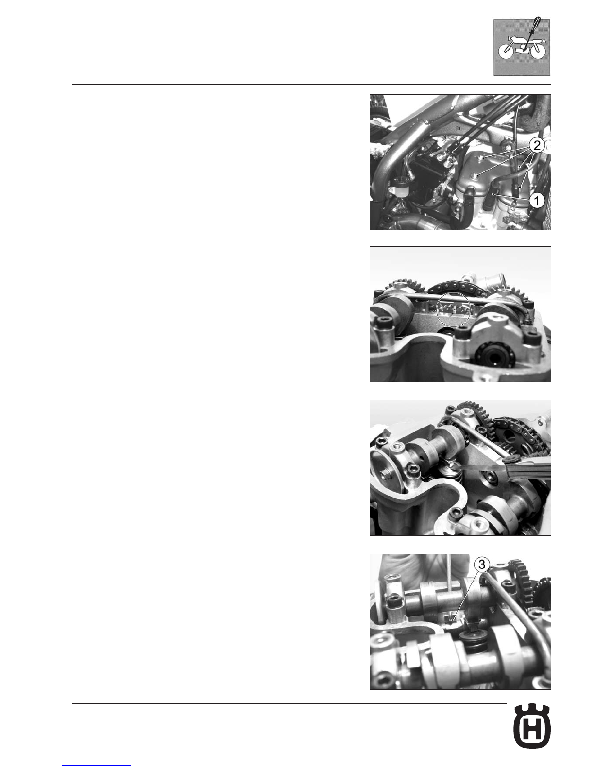
Remove spark plug (1), the four head cover screws (2) and head cover.
Engage the 2nd gear and push and pull the motorcycle back and forth to bring
the piston to Top Dead Centre. In this condition, the notch on the head will be
lined up with the two dots on the camshaft drive gear as shown in the gure.
Use a feeler gauge to make sure clearance is 0.10-0.15 mm on the INTAKE side
and 0.15-0.20 mm on the EXHAUST side.
If not so, raise the retaining clip (3) using a spring tool, push rocker arm aside,
extract shim with a pair of tweezers and check shim thickness.
Depending on what you nd, t a new shim with the required thickness (replacement shims are available in a 1.60 mm to 2.60 mm thickness range, in 0.05
mm increments) and set clip and rocker arm back into place.
Check valve clearances again. If clearances are correct, ret the parts you have
removed reversing the disassembly procedure.
Page 34
D.8 Part. N. 8000 H2051 (02-2010)
2
H006003
1
SETTINGS AND ADJUSTMENTS
Throttle cable adjustment
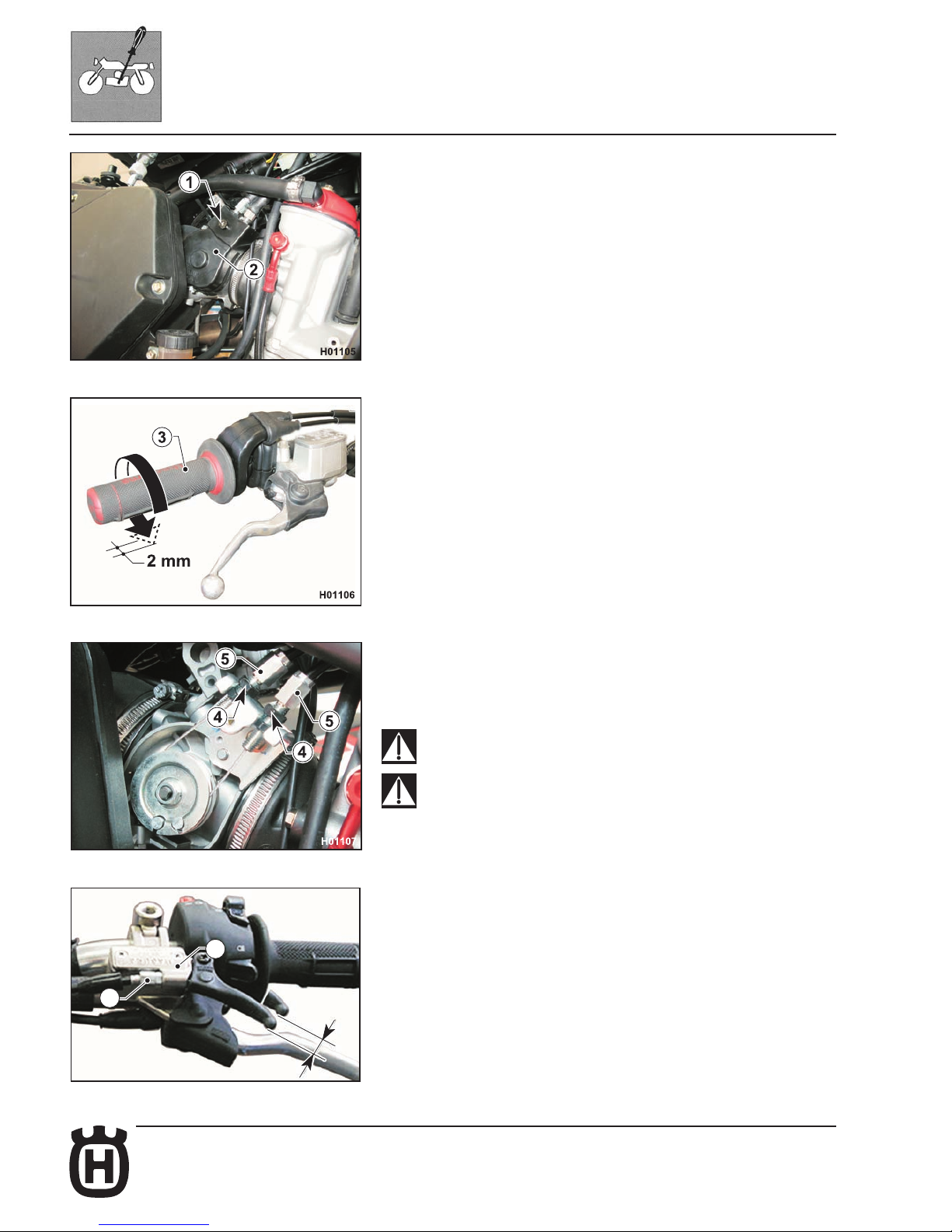
To check the correct adjustment of the throttle cable, operate as follows:
- Remove the fuel tank as described in the relevant paragraph.
- Loosen screw (1) and remove the protection cover (2);
- Turn throttle twistgrip (3) and make sure it has about 2 mm free play;
- if it is not so, loosen the lock nuts (4) and suitably turn the adjuster screws
(5) (loosen to decrease play or tighten to increase it);
- tighten back the lock nuts (4);
- reassemble all parts, in the reverse order compared to disassembly.
Operation with damaged throttle cable could result in an unsafe
riding condition.
Exhaust gas contains poisonous carbon monoxide.
Never run the engine indoors.
Enrichener lever play adjustment
The lever (1) holder features an adjuster screw (2) to adjust free play. Free play
should be about 3 mm: if not so, loosen the check nut and turn the adjuster screw
as required (loosen to decrease play or tighten to increase it).
Page 35
D.9Part. N. 8000 H2051 (02-2010)
SETTINGS AND ADJUSTMENTS
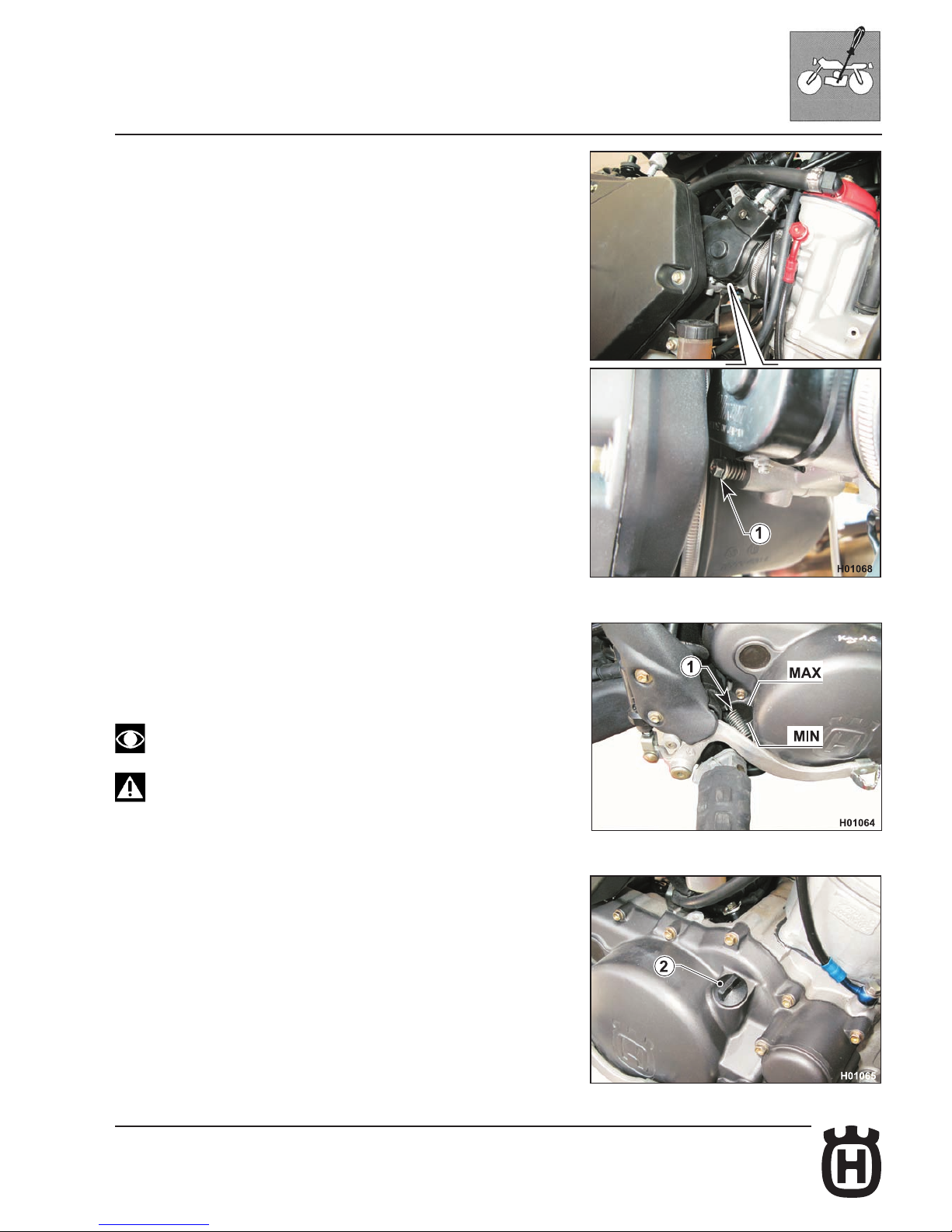
Idle adjustment
Adjust the carburettor with warm engine and with the throttle control in closed
position. Proceed as follows:
- turn the idle speed adjustment screw (1) on the throttle body, located on the
right-hand side of the vehicle, until the idle speed of 1650 RPM is reached
(turn clockwise to increase the speed and anticlockwise to reduce the speed).
To do this, you need to reach the adjuster screw from airbox front end, using the
supplied 8-10 wrench, and work lengthwise with respect to the motorcycle.
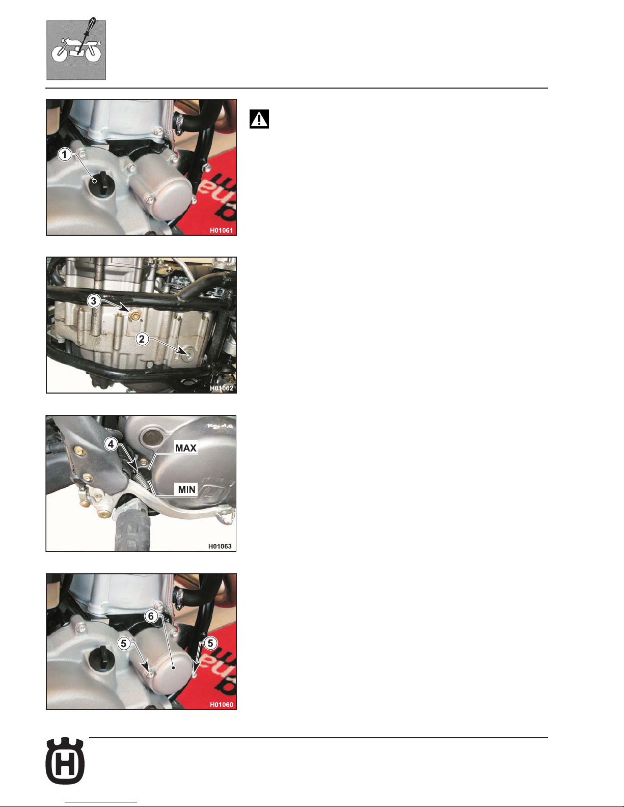
Engine oil level check
Keeping the motorcycle level and upright, check the oil level through the inspection window (1) on the right crankcase.
Make sure the level is in between the MIN and MAX notches.
To top up, remove the ller cap (2).
Perform this operation with warmed-up engine
Be careful not to touch hot engine oil
Page 36
D.10 Part. N. 8000 H2051 (02-2010)
SETTINGS AND ADJUSTMENTS
Engine oil replacement, oil lter replacement
Be careful not to touch hot engine oil.
To change engine oil, warm up engine and proceed as follows:
- Keep the motorcycle upright and place an oil drain pan under the engine.
- Remove ller cap (1) and drain plugs (2) and (3).
- Drain all engine oil.
- Ret drain plugs (M14 plug (3): 24 Nm/ 2.45 Kgm/ 18.1 ft-lb; M22 plug (2): 60
Nm/ 6.1 Kgm/ 44 ft-lb) and gaskets; be sure to clean off any debris collected
by the magnet core of plug (2).
- Fill the specied quantity of oil (see capacities table in Section A) through
the ller hole. Let the engine idle for a few minutes, stop it and wait a few
minutes to let oil settle inside the crankcase. With the motorcycle upright,
make sure the level is in between the MIN and MAX notches looking through
the oil window (4) behind the rear brake pedal.
- To change the oil lter cartridge, loosen the two retaining screws (5) and
remove the cover (6) with its O-ring.
Page 37
D.11Part. N. 8000 H2051 (02-2010)
8
7
8
SETTINGS AND ADJUSTMENTS
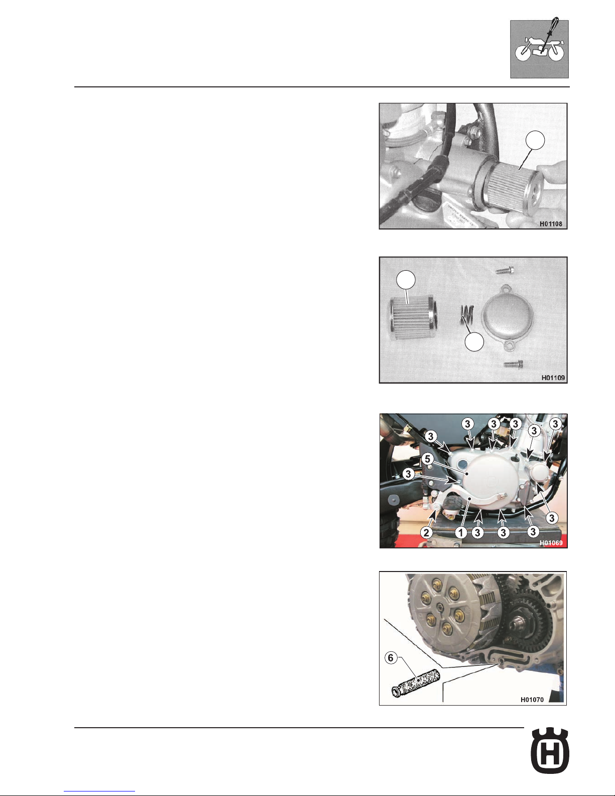
Pull out spring (7) and cartridge (8); reassemble in reverse order as for re-
moval and change the O-ring (screws 5: 9.3 Nm/ 0.95 Kgm/ 6.9 ft-lb).
Mesh lters cleaning
- Drain engine oil as described in the relevant paragraph.
Filter on right side of engine.
- Remove the rear brake lever (1) as follows: disengage the return spring
and use a 6 mm wrench to loosen the Allen screw (2).
- Loosen the eleven M6-L30 screws (3) and the two M6-L40 screws (4)
using an 8 mm ring wrench and then remove the clutch cover (5) comple-
te with lter and oil pump.
- Remove the lter (6), wash it with petrol and blow it with compressed air
and then ret it exactly in the original position.
- Reassemble all parts in the reverse order compared to disassembly and
tighten screws to the specied torque (see Section X).
Page 38
D.12 Part. N. 8000 H2051 (02-2010)
SETTINGS AND ADJUSTMENTS
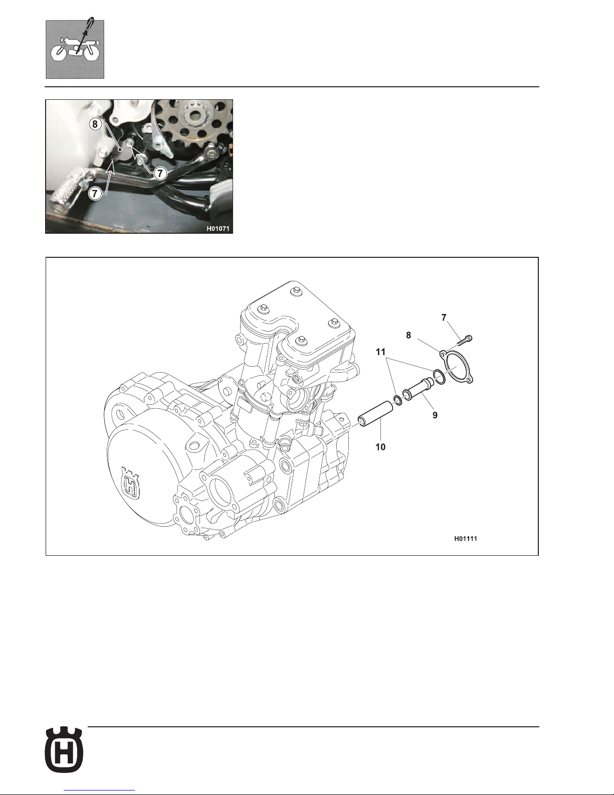
Filters on left side of engine.
- Loosen the screws (7) using an 8 mm wrench and remove the cover (8).
- Remove lters (9) (10) and their gaskets.
- Wash lters with petrol and blow them with compressed air; ret lters
exactly in their original positions using new gaskets (11) which you will
have greased properly.
- Ret cover (8) and tighten the screws (7) to the specied torque (see
Section X).
Page 39
D.13Part. N. 8000 H2051 (02-2010)
SETTINGS AND ADJUSTMENTS
Coolant level check
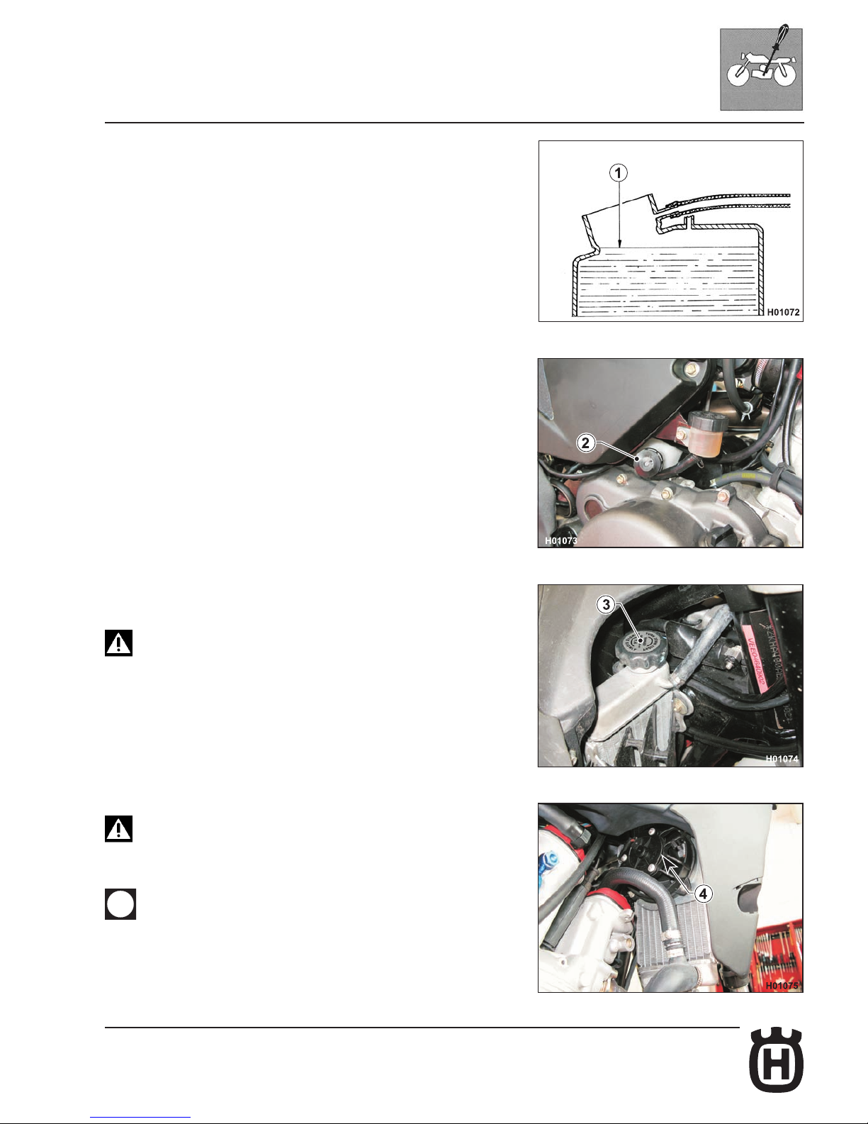
Check level (1) in right-hand radiator when engine is cold (place the motorcycle
so that it is perpendicular to the ground). The coolant should be approximately
10 mm above cells and besides, it shall not exceed the middle of the expansion
tank (2) located in front of the rear shock absorber.
The radiator cap (3) features two locking positions, the rst one is for prior discharge of pressure from the cooling system.
Avoid removing radiator cap (3) when engine is hot, as coolant
may spout out and cause scalding.
Because the cooling fan (4) can be activated even when the start
switch is in OFF position, always keep at a safe distance from the
fan blades.
Difculties may arise in eliminating coolant from painted surfaces.
If this occurs, wash off with water.
Page 40
D.14 Part. N. 8000 H2051 (02-2010)
SETTINGS AND ADJUSTMENTS
Coolant replacement
Coolant shall be replaced with cold engine and coolant.
Standard procedure
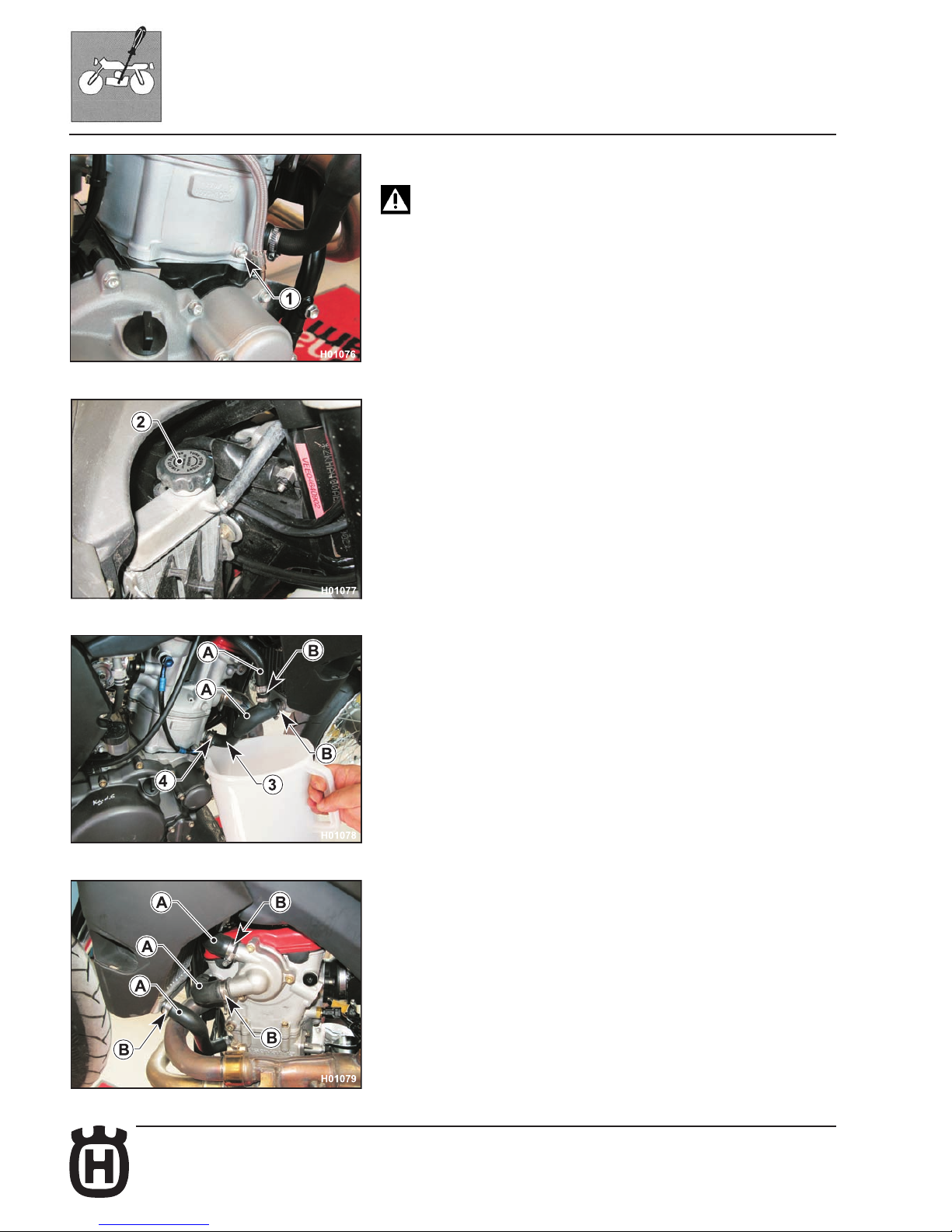
- Place a vessel on the R.H. side of the cylinder, under the coolant drain screw
(1). FIRST remove the screw (1) using a ... mm wrench, then SLOWLY open
the R.H. radiator cap (2); slope the motorcycle on the right side to drain the
coolant easily in the vessel. Reassemble the screw (1).
Fast procedure
- Place a vessel on the R.H. side of the cylinder, under the tube (3).
- Loosen clamp (4) and disconnect tube (3) from the engine.
- SLOWLY open the R.H. radiator cap (2); slope the motorcycle on the right
side to drain the coolant easily in the vessel.
- Reassemble the tube (3) and tighten the clamp (4) (See Section X or Section
F for tightening torque)
Standard procedure
- Pour the necessary quantity of coolant in the radiator then warm up the engine
in order to eliminate any possible air bubbles.
- Allow the coolant to cool down then remove cap (2) and check the level as
explained under “Coolant level check”.
- Periodically check the connecting hoses (see “Section B”); this will avoid
coolant leakage and consequent engine seizure. If hoses (A) show cracks,
swelling or hardening due to sheaths desiccation, their replacement shall be
advisable.
- Check the correct tightening of the clamps (B).
Page 41
D.15Part. N. 8000 H2051 (02-2010)
SETTINGS AND ADJUSTMENTS
Clutch plate replacement
- Drain engine oil as described in the relevant paragraph.
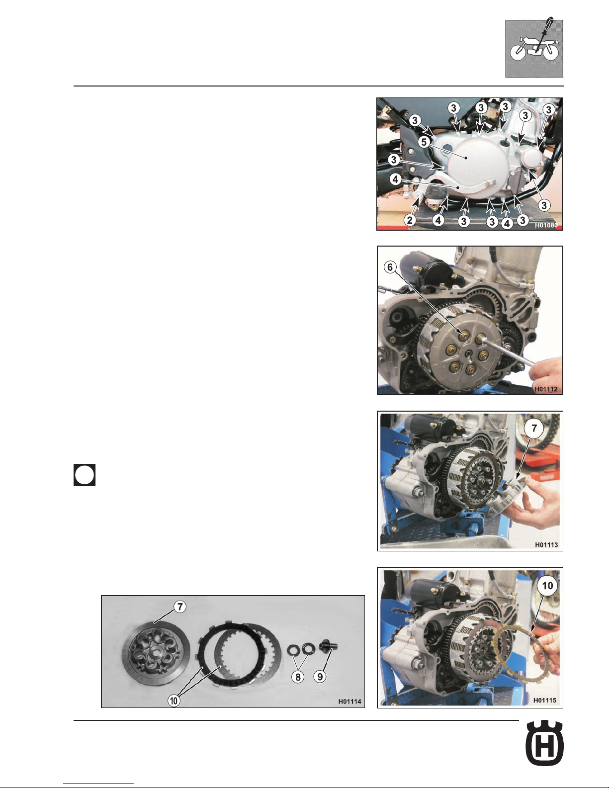
- Remove the rear brake lever (1) as follows: disengage the return spring and
use a 6 mm wrench to loosen the Allen screw (2).
- Loosen the eleven M6-L30 screws (3) and the two M6-L40 screws (4) using
an 8 mm ring wrench and then remove the clutch cover (5) complete with
lter and oil pump.
Clutch disassembly
- Using an 8 mm wrench, unscrew the six screws (6) securing the clutch
springs. Remove washer, springs, pressure plate (7), washer, axial bearing
(8) and clutch plate pack (10).
Collect actuator plate (9) and rod (5) from gearbox input shaft.
- Lubricate the new plates with engine oil and install them (always start with
a friction plate).
Ret clutch actuator plate, bearing and pressure plate.
Tighten the spring screws gradually in a cross pattern (8 Nm - 0.8 Kgm - 5.8 ft/
lb).
When retting the clutch cover (8 Nm - 0.8 Kgm - 5.8 ft/lb), check gasket for
wear and replace as required.
For additional information on assembly procedures, see Section
"H" Engine assembly.
Page 42
D.16 Part. N. 8000 H2051 (02-2010)
SETTINGS AND ADJUSTMENTS
Hydraulic clutch lever adjustment and uid level check
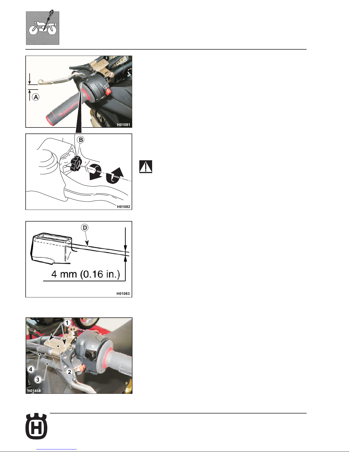
Free play (A) must be at least 3 mm.
The lever position can be adjusted to suit the rider hand size.
To decrease the lever distance from the handgrip, rotate the adjuster (B)
CLOCKWISE.
To increase the lever distance from the handgrip, rotate the adjuster (B)
COUNTER CLOCKWISE.
Fluid level is checked as follows:
- remove screws (1), cover (2) and rubber diaphragm from the control;
- keep the control cylinder (3) in a horizontal position and make sure that uid
level has not dropped lower than 4 mm (0.16 in.) below the upper edge (D)
of master cylinder body;
- if needed, top up with the uid specied in the CAPACITIES TABLE, SECTION A.
NEVER use brake uid.
Ret any parts you have removed.
Periodically check the connecting hose (see “Scheduled Maintenance Chart ”);
if hose (C) is worn or cracked, its replacement is advised.
Page 43
D.17Part. N. 8000 H2051 (02-2010)
SETTINGS AND ADJUSTMENTS
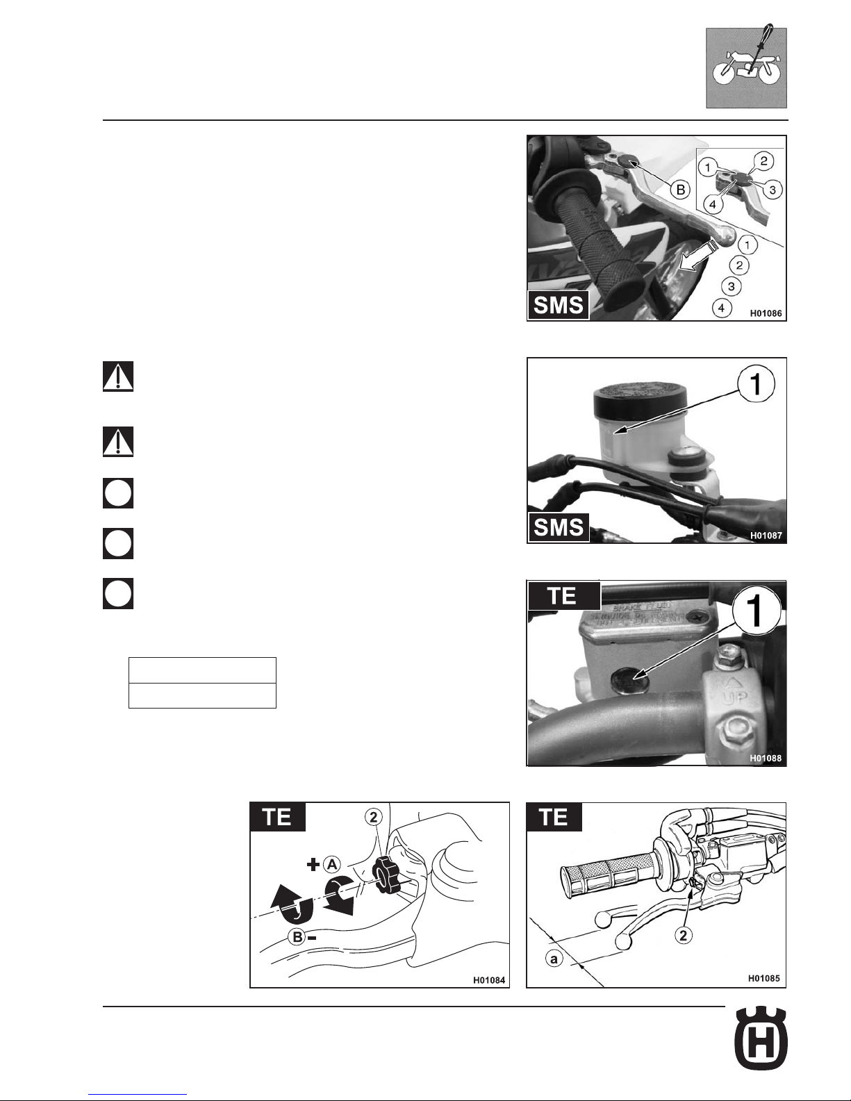
Front brake lever adjustment and uid level check
On the SMS model the lever position can be adjusted (4 settings available) to
suit the rider hand size.
To decrease the lever distance from the handgrip, turn the adjuster (B) CLOCKWISE. To increase the lever distance from the handgrip, turn the adjuster (B)
COUNTER CLOCKWISE. On the TE models the adjuster (2), located on the
control lever, allows adjusting of the free play (a).
Free play (a) must be at least 3 mm.
The level of the uid in master cylinder reservoir must never be below the minimum
value (1), which can be checked from the window on the rear side of the master
cylinder body (TE). For (SMS) model, check the level on the clear reservoir.
A decrease of the uid level will let air into the system, hence an extension of
the lever stroke.
If the brake lever feels mushy when pulled, there may be air in the brake
line or the brake may be defective: CHECK THE BRAKING SYSTEM
(see Section "L").
Too much brake lever free play may reduce braking action: CHECK
BRAKE PAD THICKNESS (see Section "L").
Do not spill brake uid onto any painted surface or lens (for example
lights lens).
Do not mix two brands of uid. Completely change the brake uid in the
brake system if you wish to switch to another uid brand.
Brake uid may cause irritation. Avoid contact with skin or eyes. In case
of contact, ush thoroughly with water and call a doctor if your eyes were
exposed.
A: to increase clearance
B: to decrease clearance
Page 44
D.18 Part. N. 8000 H2051 (02-2010)
SETTINGS AND ADJUSTMENTS
Rear brake pedal position adjustment
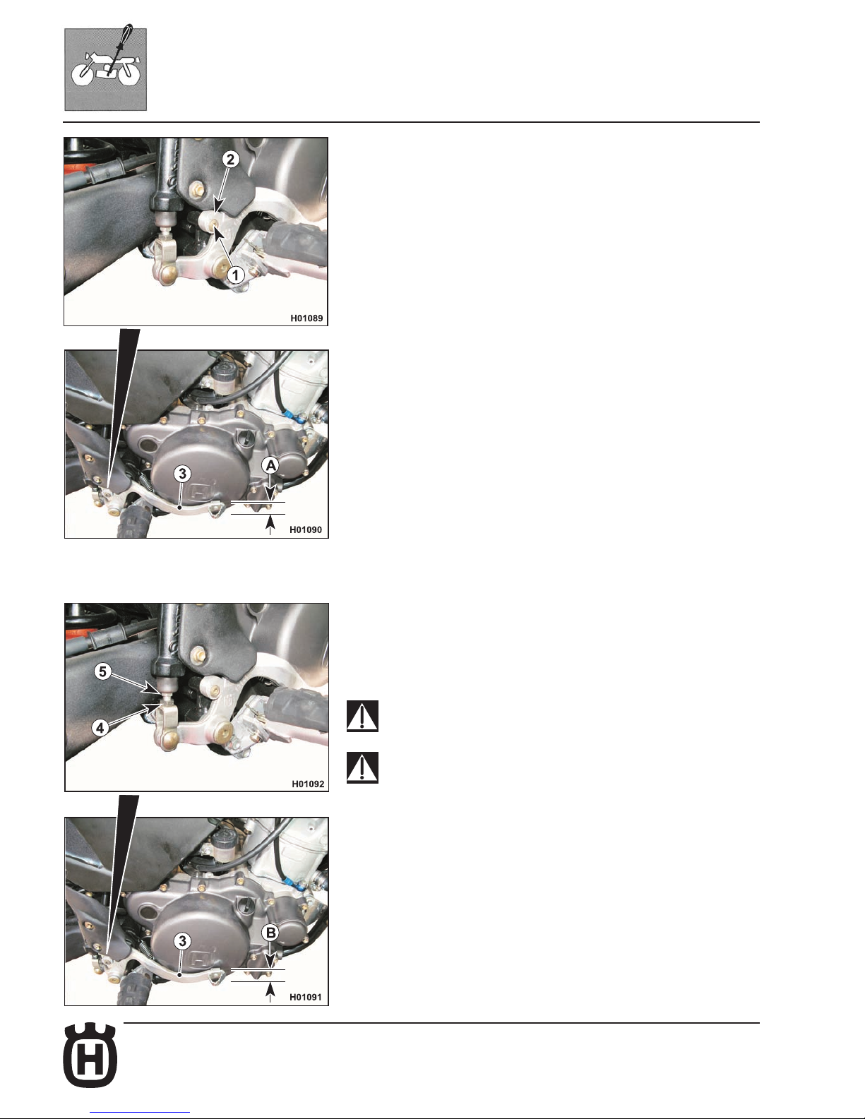
The position of the rear brake pedal with respect to the footrest may be adjusted
according to individual needs.
For adjusting, proceed as follows:
- Loosen the screw (1).
- turn the cam (2) in order to raise or lower the brake pedal (3) within the range
available (A);
- When nished, tighten the screw (1).
Once this adjustment is completed, adjust the free play of the pedal following the
instructions provided in paragraph "Rear brake pedal free play adjustment".
Rear brake pedal free play adjustment
The rear brake pedal (3) should have a free play (B) (5 mm) before the brakes
begin to bite. Should this not happen, operate as follows:
- loosen nut (4);
- operate the pump rod (5) to increase or decrease the free play;
- tighten nut (4) at the end of the operation.
When the free play requirement is not met, the brake pads will be subjected
to an early wear that may lead to TOTAL BRAKE INEFFECTIVENESS.
If the brake pedal feels mushy when pulled, there may be air in the brake
line or the brake may be defective. CHECK THE BRAKING SYSTEM (see
Section L).
Page 45
D.19Part. N. 8000 H2051 (02-2010)
SETTINGS AND ADJUSTMENTS
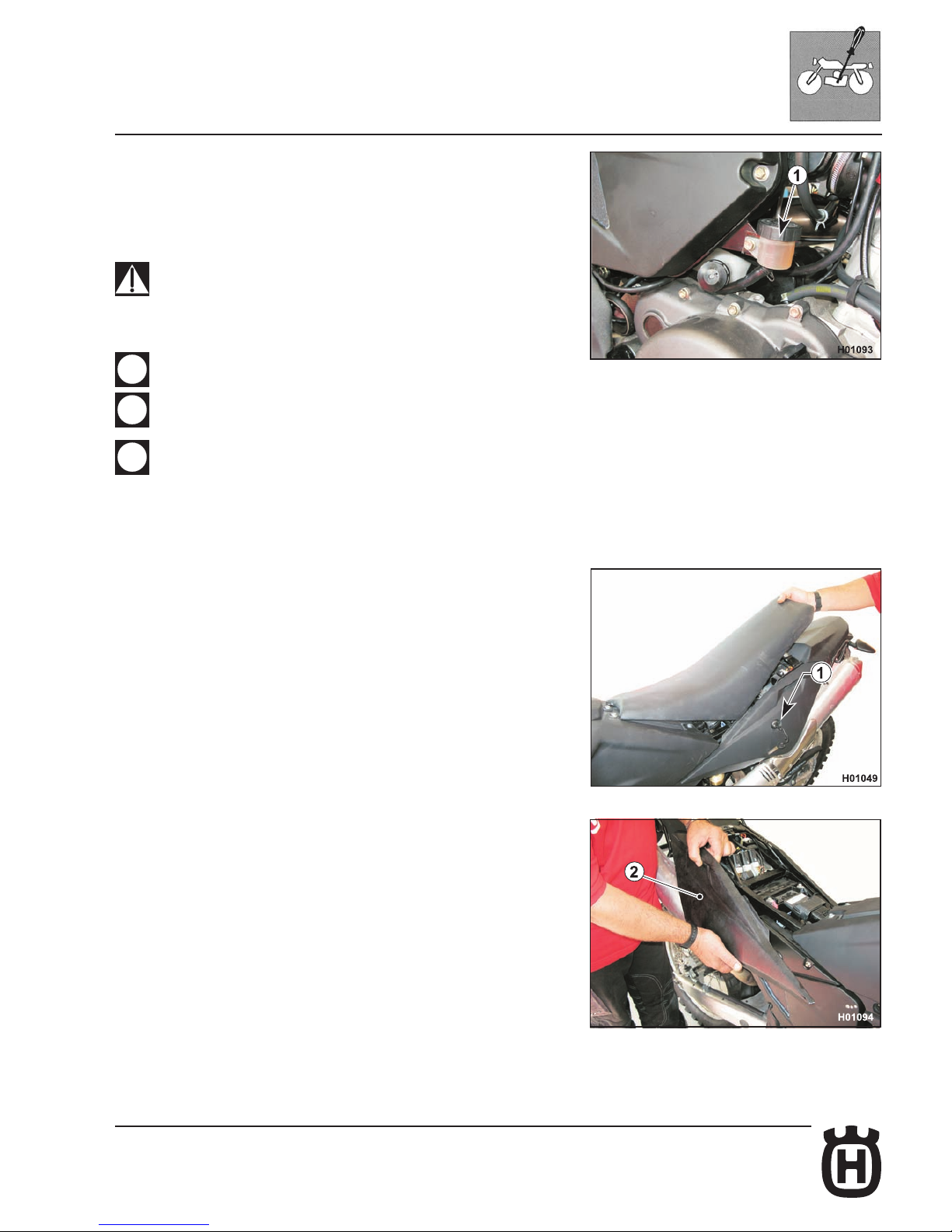
Rear brake uid level check
Master cylinder uid level shall never drop below the minimum notch shown on
the clear reservoir (1).
A decrease of the uid level will let air into the system, hence an extension of
the lever stroke.
If the brake pedal feels mushy when pulled, there may be air in the brake
lines or the brake may be defective. Since it is dangerous to operate the
motorcycle under such conditions, have the brake system immediately
checked (see Section L)
Do not spill brake uid onto any painted surface or light lens.
Do not mix two brands of uid. Completely change the brake uid in the
brake system if you wish to switch to another uid brand.
Brake uid may cause irritation. Avoid contact with skin or eyes. In case
of contact, ush thoroughly with water and call a doctor if your eyes were
exposed.
Air lter check
- Insert the key in latch (1) then turn clockwise to release the saddle lock;
remove the saddle.
- Disengage rear right-hand side panel (2) from lter cover then slide it toward
vehicle front.
Page 46
D.20 Part. N. 8000 H2051 (02-2010)
SETTINGS AND ADJUSTMENTS
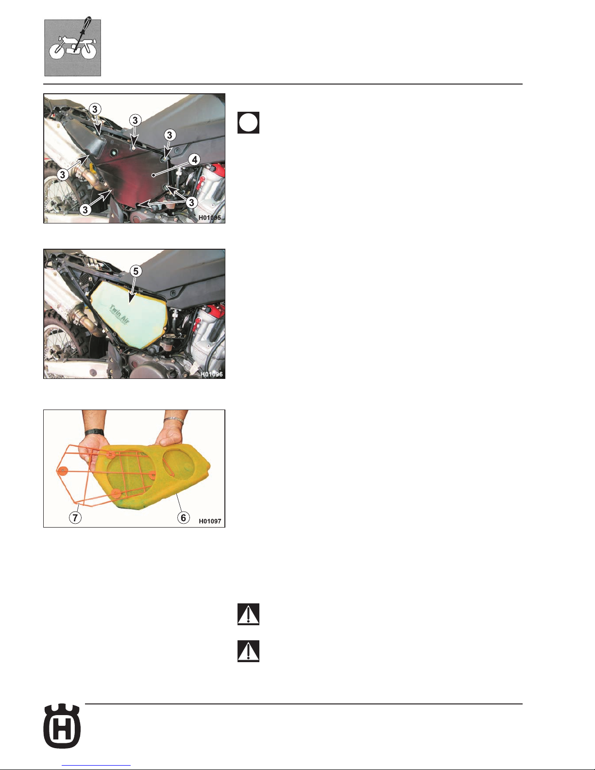
- Loosen the seven screws (3) and remove the lter cover (4).
The screws have a different length, it is recommended to mark them in
order to favour correct reassembly.
- Remove the lter (5) together with support frame.
- Slide out the ltering element (6) from the support frame (7).
Air lter cleaning
Wash the lter with a specic detergent (CASTROL FOAM AIR FILTER CLEANER or similar) then dry it fully (wash lter with gasoline only in case of need).
Plunge the lter in special oil for lters (CASTROL FOAM AIR FILTER OIL or
similar), then wring it to drain superuous oil.
Do not use fuel or a low ash-point solvent to clean the ltering element.
A re or explosion could result.
Clean the ltering element in a well ventilated area and do not allow
sparks or ames anywhere near the working area.
Page 47
D.21Part. N. 8000 H2051 (02-2010)
SETTINGS AND ADJUSTMENTS
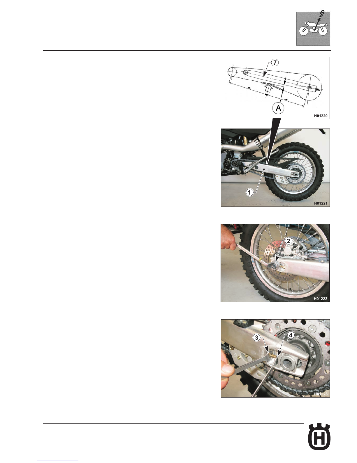
Chain adjustment
Chain should be checked, adjusted and lubricated as per the Maintenance
Chart to ensure safety and prevent excessive wear. If the chain becomes badly
worn or is poorly adjusted (i.e., if it is too loose or too taut), it could escape from
sprocket or break.
Make sure that the chain features a slack (A) measuring approximately 12 mm,
as shown in the nameplate (1) on swingarm.
If it is not, proceed as follows:
- on the right side, with a 27 mm Allen wrench, loosen the locking nut (2) of
the wheel axle;
- loosen the check nuts (3) on both chain tensioners with a 12 mm wrench and
work on the screws (4) with a 10 mm wrench to achieve the right tension;
- when the adjustment is completed, tighten the check nuts (3) and the wheel
axle nut (2) (142.1 Nm - 14.5 Kgm - 104.8 ft/lb).
After adjustment, always make sure that chain has a slack of 12 mm.
Page 48
D.22 Part. N. 8000 H2051 (02-2010)
H006004
4
3
H01098
2
1
1
SETTINGS AND ADJUSTMENTS
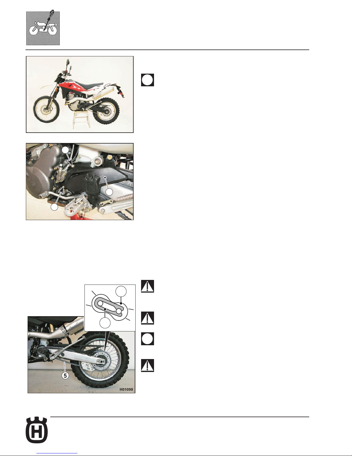
Chain lubrication
Lubricate the chain following these instructions.
Never use grease to lubricate the chain. Grease helps to accumulate dust
and mud, which act as abrasive and help to rapidly wear out the chain,
the front and rear sprockets.
Disassembling and cleaning
When particularly dirty, remove and clean the chain before lubrication. Proceed
as follows:
- Set a stand or a block under the engine and see that the rear wheel is lifted
from the ground.
- Remove: screws (1), sprocket guard (2), clip (3), master link (4) with its Orings and chain (5). To reassemble, reverse the above procedure.
Make sure that the chain is neither worn out nor damaged. If the rollers or the
links are damaged, replace the chain by following the instructions given in the
Scheduled Maintenance Chart. Ensure that the sprockets are not damaged.
Wash and clean the chain as described hereunder.
Washing a chain without O-rings
Wash using petroleum, naphtha or parafn oil. Never use fuel, trichloroethylene
or solvents, as the O-rings may get damaged.
Use instead special sprays for chains with O-rings.
Lubricating an O-ring chain
Lubricate all metallic and rubber (O-ring) elements using a brush and engine oil
with SAE 80-90 viscosity, inside and outside parts.
If the chain has been cut, reassemble it using the master link.
Assemble the master link clip (3) by setting the closed side facing the chain
direction of rotation, as shown in the gure.
Reassemble all parts, in the reverse order compared to disassembly.
The master link is the most critical safety part in the drive chain. Even if
the master links are reusable when in good conditions, for safety purposes
we advise using a new master link when reassembling the chain.
Accurately adjust the chain as described in the relevant paragraph.
The chain lubricant shall NEVER get in contact with the tyres or the rear
brake disc.
Chain tensioner roller, chain guide roller, chain guide, chain slider
Check the wear of the above-mentioned elements and replace them when
necessary.
Check the chain guide alignment, and remember that a bent element
can cause chain early wear. In this case, chain might unwrap from the
sprocket.
Accurately adjust the chain as described in the relevant paragraph.
Page 49
D.23Part. N. 8000 H2051 (02-2010)
SETTINGS AND ADJUSTMENTS
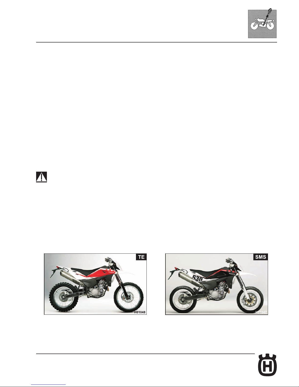
Suspension
Standard suspensions setting derives from several extensive demanding tests in
various usage conditions of the TE and SMS vehicles. If you intend to use them
on more specic ground, following are a few guidelines for setup. Always start
from the suspensions standard setting before making any change. Afterwards,
increase or decrease the adjusting clicks, one at a time.
HARD GROUND
Front fork: softer compression setting.
Shock absorber: softer compression setting.
SANDY GROUND
Front fork: harder compression setting.
Shock absorber: harder compression, and especially harder rebound settings.
Work on the spring preload to lower the motorcycle riding height (rear end).
MUDDY GROUND
Front fork: harder compression setting.
Shock absorber: harder compression and rebound settings; Work on the spring
preload to lift the motorcycle riding height (rear end).
ALWAYS remember that all the motorcycles and their parts used in com-
petitions of any type are excluded from the warranty and that all modications to standard conguration cause THE VEHICLE NON COMPLIANCE
WITH TYPE-APPROVAL REQUIREMENTS and it is hence unsuitable for
circulating on public roads: consequently it may be used only in “CLOSED
CIRCUITS” by authorised subjects holding the relevant driving licence or
authorisation.
Page 50
D.24 Part. N. 8000 H2051 (02-2010)
A
C
B
SETTINGS AND ADJUSTMENTS
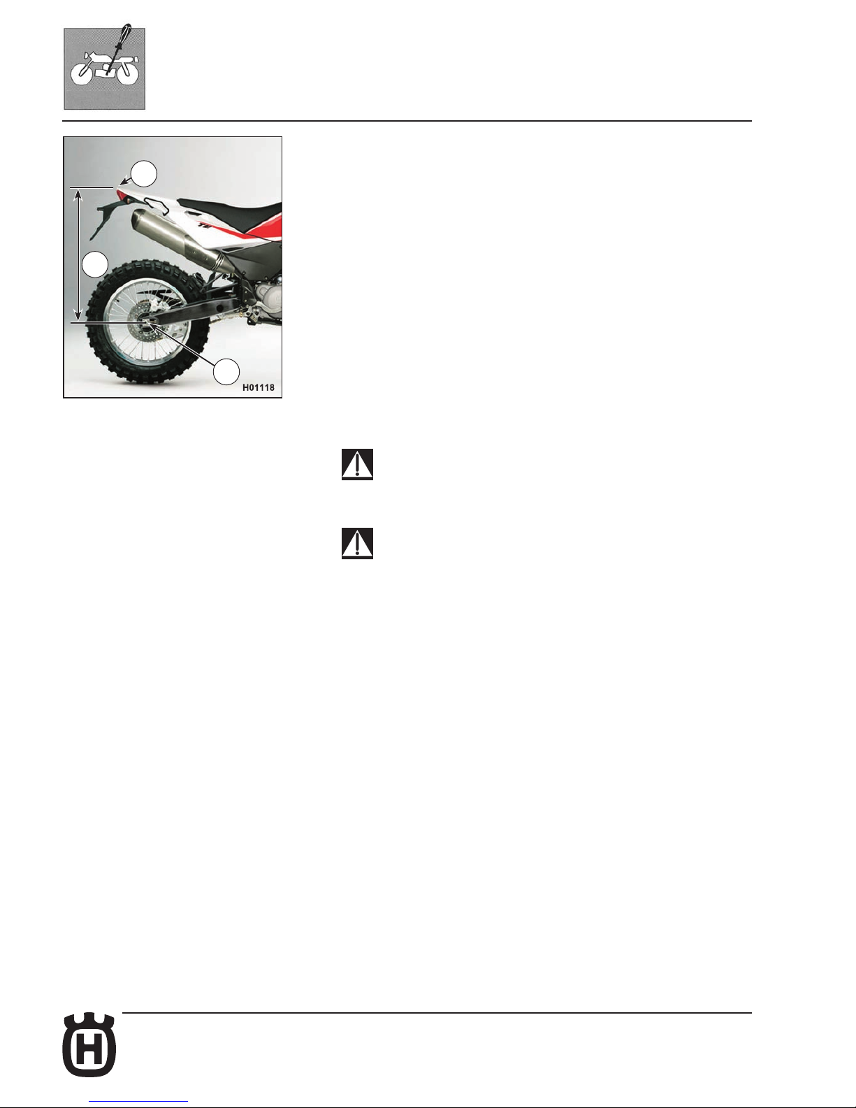
Shock absorber adjustment
The rear shock absorber is calibrated for running with the rider plus a small bag
only. It is thus recommended to adjust the shock absorber setting (spring preload)
when riding with a passenger.
Proceed as follows:
1. Place the motorcycle on the stand and measure distance (A).
2. Sit on the motorcycle in normal riding position with full riding gear on.
3. Have someone else measure distance (A) again.
4. The difference between these two measurements is the distance the rear end
settles when the rider sits on the motorcycle (RIDER SAG). Recommended
rider sag is 90 mm with a cold shock absorber and 85-87 mm with a warm
shock absorber.
5. To achieve correct rider sag for your weight, adjust the spring preload of the
shock absorber (see relevant paragraph).
The shock absorber adjustment affects both the stability and the handling
of the motorcycle. After changing the standard suspension setting, ride
with care. We advise measuring the reference distance “A” before making
any change.
Never disassemble the shock absorber, which contains compressed gas.
Contact your Husqvarna Dealer for any major service.
B: rear mudguard top height
C: rear wheel axle height
Page 51
D.25Part. N. 8000 H2051 (02-2010)
4
SETTINGS AND ADJUSTMENTS
Shock absorber spring preload adjustment
Proceed as follows:
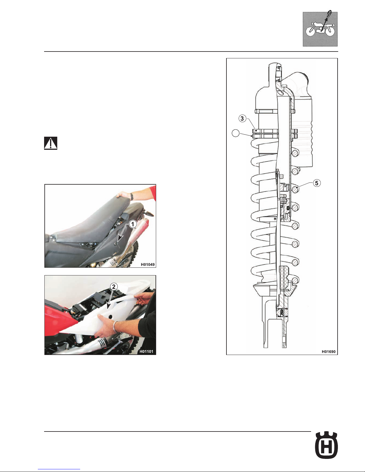
1. Insert the key in latch (1) then turn clockwise to release the saddle lock;
remove the saddle.
2- Disengage rear left-hand side panel (2) then slide it toward vehicle front.
3. Clean lock ring nut (3) and adjuster ring nut (4) of the spring (5).
4. Either with a hook wrench or an aluminium punch, loosen the lock ring nut.
5. Turn the adjuster ring nut as required.
6. Adjust preload to suit your weight or riding style and tighten the lock ring nut
rmly (tightening torque 50 Nm - 5 Kgm - 67.8 ft/lb).
7. Reassemble the L.H. side panel and the saddle.
Be careful not to touch hot exhaust pipe while adjusting the shock absor-
ber.
Page 52
D.26 Part. N. 8000 H2051 (02-2010)
3
+
-
SETTINGS AND ADJUSTMENTS
Shock absorber damping adjustment
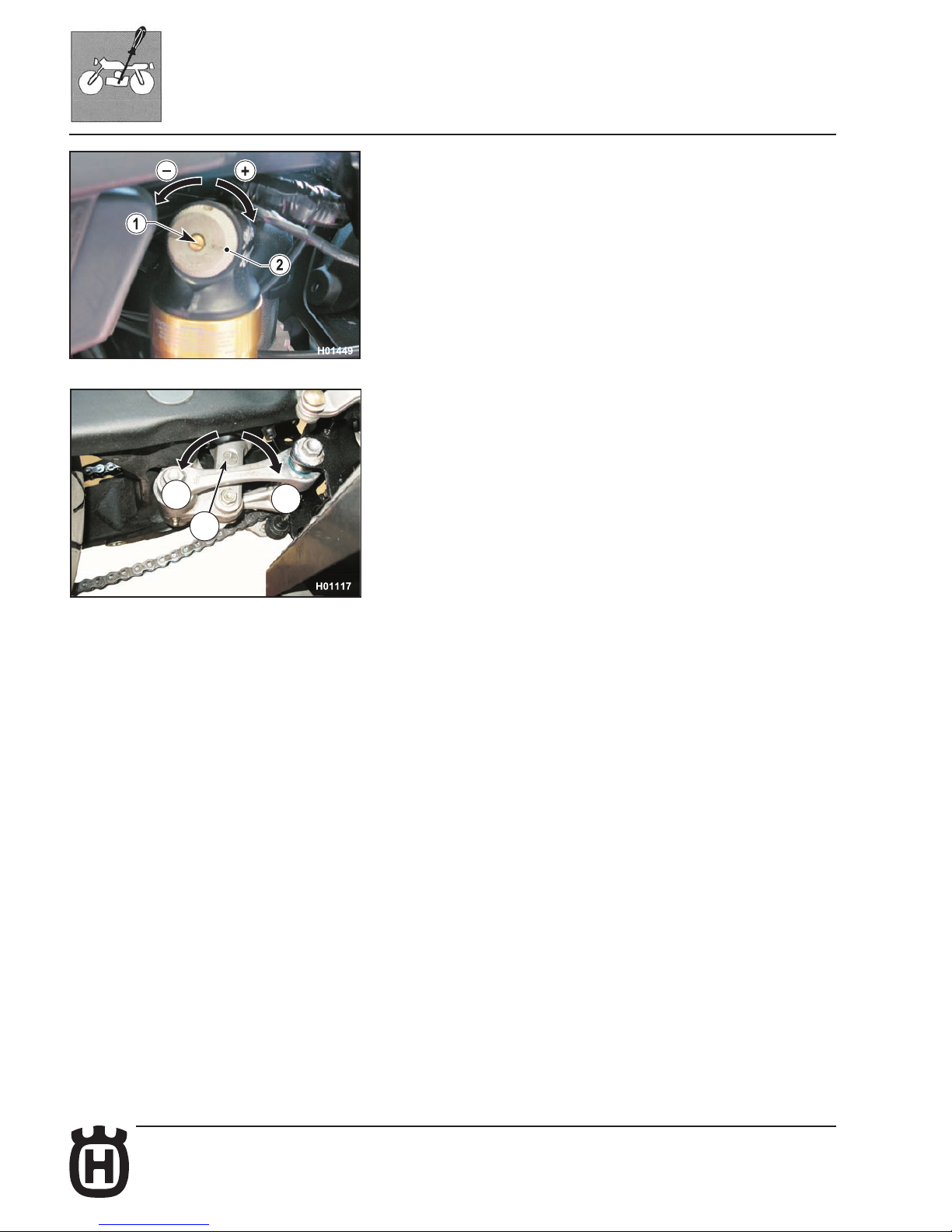
Adjustment of the compression stroke is independent from the rebound stroke.
A) COMPRESSION - Standard setting:
1) Low damping speed:
fully open
(adjuster 1)
2) High damping speed:
fully open
(adjuster 2)
To reset the standard setting, turn upper adjuster screws (1) and (2) clockwise
until reaching fully closed position. Then turn them back the number of clicks
specied above.
In order to obtain a smooth braking action, turn the adjuster screws counter
clockwise. Vice versa to obtain a harder braking action.
B) REBOUND - Standard setting:
TE: -20 clicks (± 2 clicks)
SMS: -26 clicks (± 2 clicks)
To reset the standard setting, turn lower adjuster (3) clockwise until reaching
fully closed position. Then turn it back by the mentioned clicks.
In order to obtain a smooth braking action, turn the adjuster screw counter
clockwise. Vice versa to obtain a harder braking action.
Page 53
D.27Part. N. 8000 H2051 (02-2010)
a)
C
D
F
b)
SETTINGS AND ADJUSTMENTS
MARZOCCHI front fork adjustment
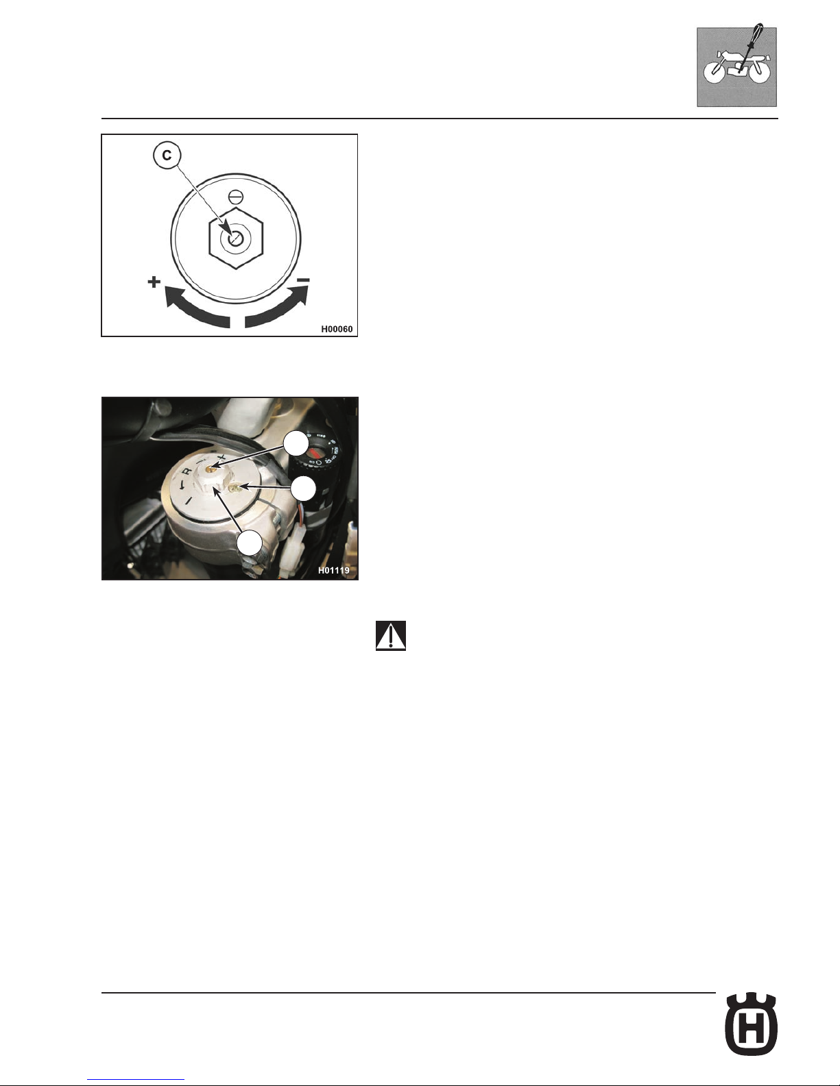
a) REBOUND (TOP ADJUSTER)
Standard setting: -12 clicks.
To reset standard setting, turn adjuster (C) clockwise to reach the fully closed
position; then, turn it back by the mentioned clicks. In order to obtain a smooth
braking action, turn the adjuster screw counter clockwise. Vice versa to obtain
a harder braking action.
b) air vent (to carry out after each competition, or monthly).
Set the motorcycle on a central stand, release the fork fully extended and loosen
the air vent valve (D). Once this operation is over, tighten the valve.
NEVER loosen the screw (F).
NOTE: Never force the adjuster screws beyond the maximum open and closed
positions.
Page 54
D.28 Part. N. 8000 H2051 (02-2010)
A
SETTINGS AND ADJUSTMENTS
Fork oil level
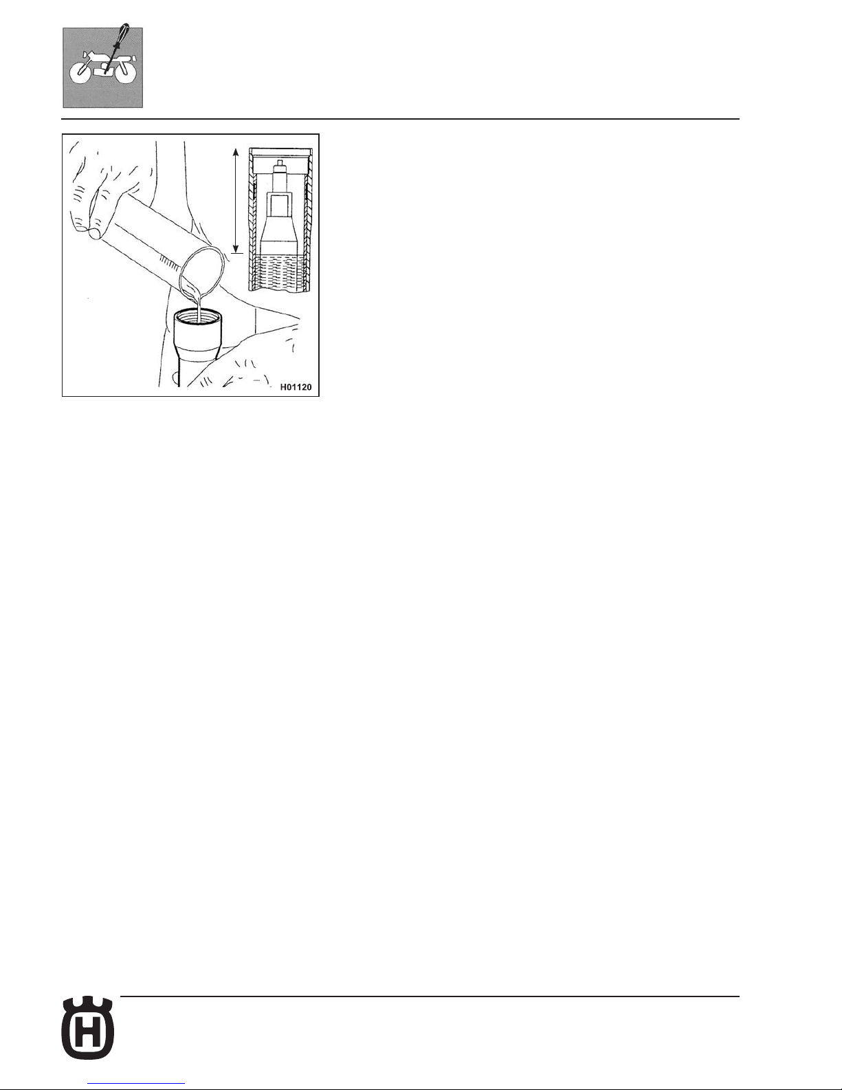
For regular fork operation, both legs must be provided with the necessary oil quantity. Remove the fork legs from the fork to check the oil level. Work as follows:
- remove the damper rod caps;
- remove springs from the legs letting the oil drain into the legs;
- bring fork to stroke end;
- check that the level is at distance “A” below the upper limit of damper rod.
Oil quantity in each fork leg
- TE: 630 cm
3
- SMS: 600 cm
3
A=80mm (3.15 in.) - TE
A=90mm (3.54 in.) - SMS
NOTE: Flexibility index of the standard springs:
K=5 N/mm (TE)
K=5.4 N/mm (SMS)
NOTE: Always replace both the spring and the spacers to keep the preload
value unchanged.
Page 55
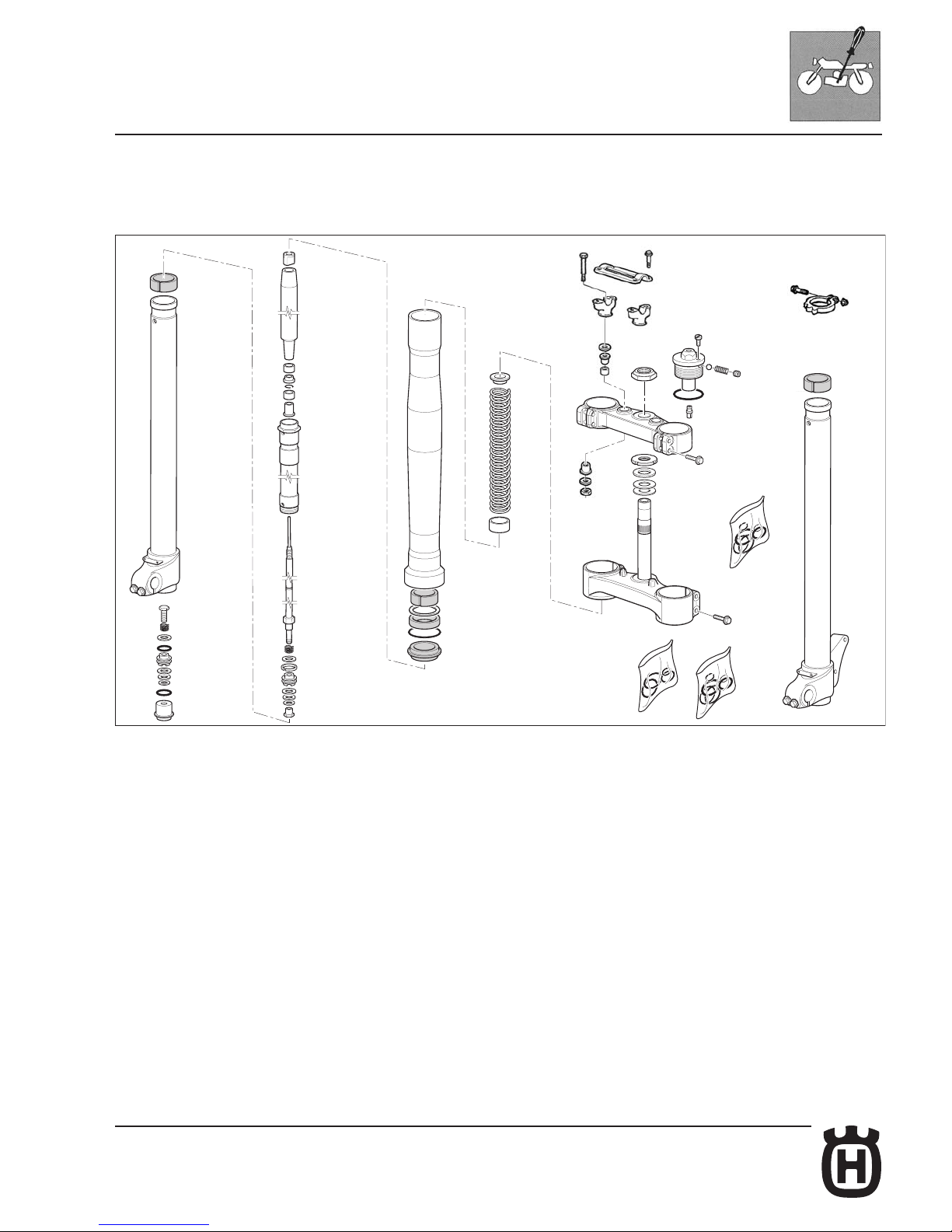
D.29Part. N. 8000 H2051 (02-2010)
H006002
SETTINGS AND ADJUSTMENTS
MARZOCCHI front fork springs
STANDARD
K=4.8 N/mm (spring + spacer part no. 8000 H1994)
Page 56
D.30 Part. N. 8000 H2051 (02-2010)
SETTINGS AND ADJUSTMENTS
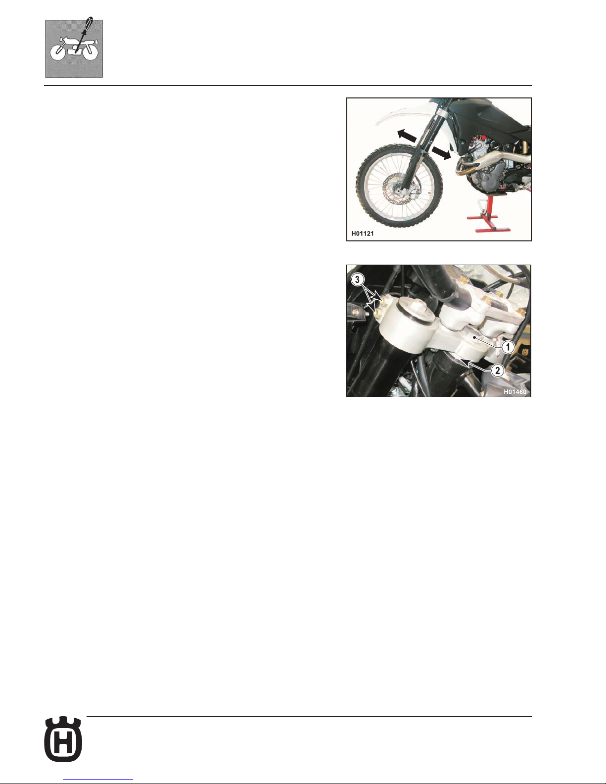
Steering bearing clearance adjustment
For safety reasons, the steering should always be adjusted so that the handlebar
turns freely and without play. To check steering adjustment, set a stand or a block
under the engine and see that the front wheel is lifted from the ground. Press
lightly on the handlebar grips to cause the front end to rotate; the handlebar should
turn smoothly. Sit on the ground in front of the front wheel and hold the lower
ends of the fork legs. Push and pull in a front to rear motion to feel for play.
If any play is detected, adjust as follows:
- Loosen the steering head tube nut (1);
- Loosen the four bolts (3) that secure the fork legs to the steering head; Turn the steering head tube ring nut (2) clockwise using the special key until
achieving correct play adjustment;
- tighten the steering head tube nut (1) to 8-9 Kgm. (78.4-88.3 Nm);
- Tighten the four bolts (3) on the steering head to 22.5-26.5 Nm (2.3-2.7
Kgm).
Page 57
D.31Part. N. 8000 H2051 (02-2010)
SETTINGS AND ADJUSTMENTS
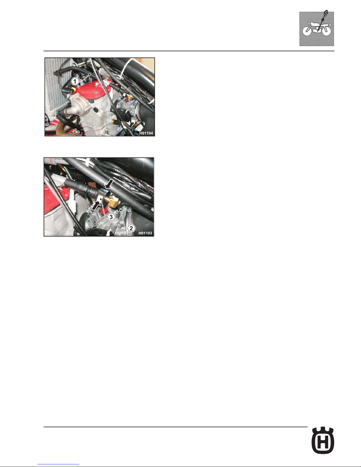
Supply hose check
Remove saddle and tank as outlined in the relevant paragraphs.
Check the hose (1) running from pump to throttle body (2).
To replace the hose, squeeze the two retainer tabs (3) on throttle body tting.
Page 58
D.32 Part. N. 8000 H2051 (02-2010)
SETTINGS AND ADJUSTMENTS
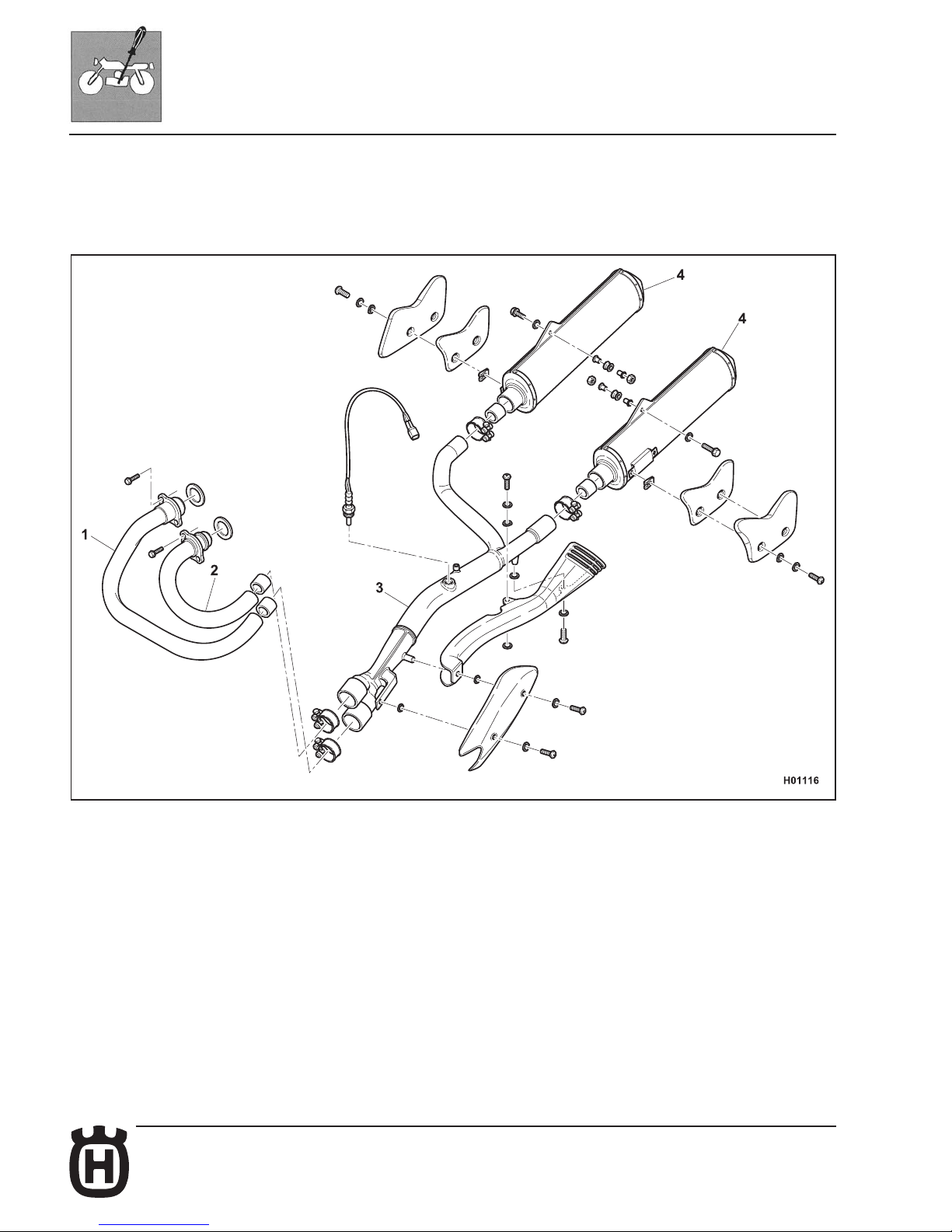
Exhaust system check
Remove exhaust system components as described in Section "E".
Check pipes (1), (2) and (3) and silencers (4) for cracks or damage:
replace if cracked or damaged.
Page 59
E.1Part. N. 8000 H2051 (02-2010)
E
GENERAL PROCEDURES
Section
Page 60
E.2 Part. N. 8000 H2051 (02-2010)
GENERAL PROCEDURES
Foreword ......................................................................................................E.3
Saddle removal.............................................................................................E.4
Side panel removal .......................................................................................E.4
Battery removal ............................................................................................E.5
Exhaust system removal ..............................................................................E.6
Air box removal...........................................................................................E.10
Throttle body removal .................................................................................E.12
Removing the rear chassis complete with mudguard .................................E.14
Fuel tank removal .......................................................................................E.17
Fuel tank disassembly (scoops and fuel pump) .........................................E.20
Expansion tank removal. ............................................................................E.22
Removing utilities (solenoid starter, relays, fuses, asher).........................E.23
Electronic control unit removal ...................................................................E.24
Voltage regulator removal...........................................................................E.24
Ignition coil removal ....................................................................................E.24
Electric cooling fan removal........................................................................E.25
Front mudguard removal. ...........................................................................E.25
Horn removal. .............................................................................................E.25
Headlamp removal and bulb replacement ..................................................E.26
Digital dashboard removal. .........................................................................E.28
Headlamp fairing removal...........................................................................E.29
Ignition switch removal. ..............................................................................E.30
Thermal expansion valve removal. .............................................................E.31
Secondary drive chain removal ..................................................................E.32
Engine removal...........................................................................................E.32
Radiator removal ........................................................................................E.37
Page 61
E.3Part. N. 8000 H2051 (02-2010)
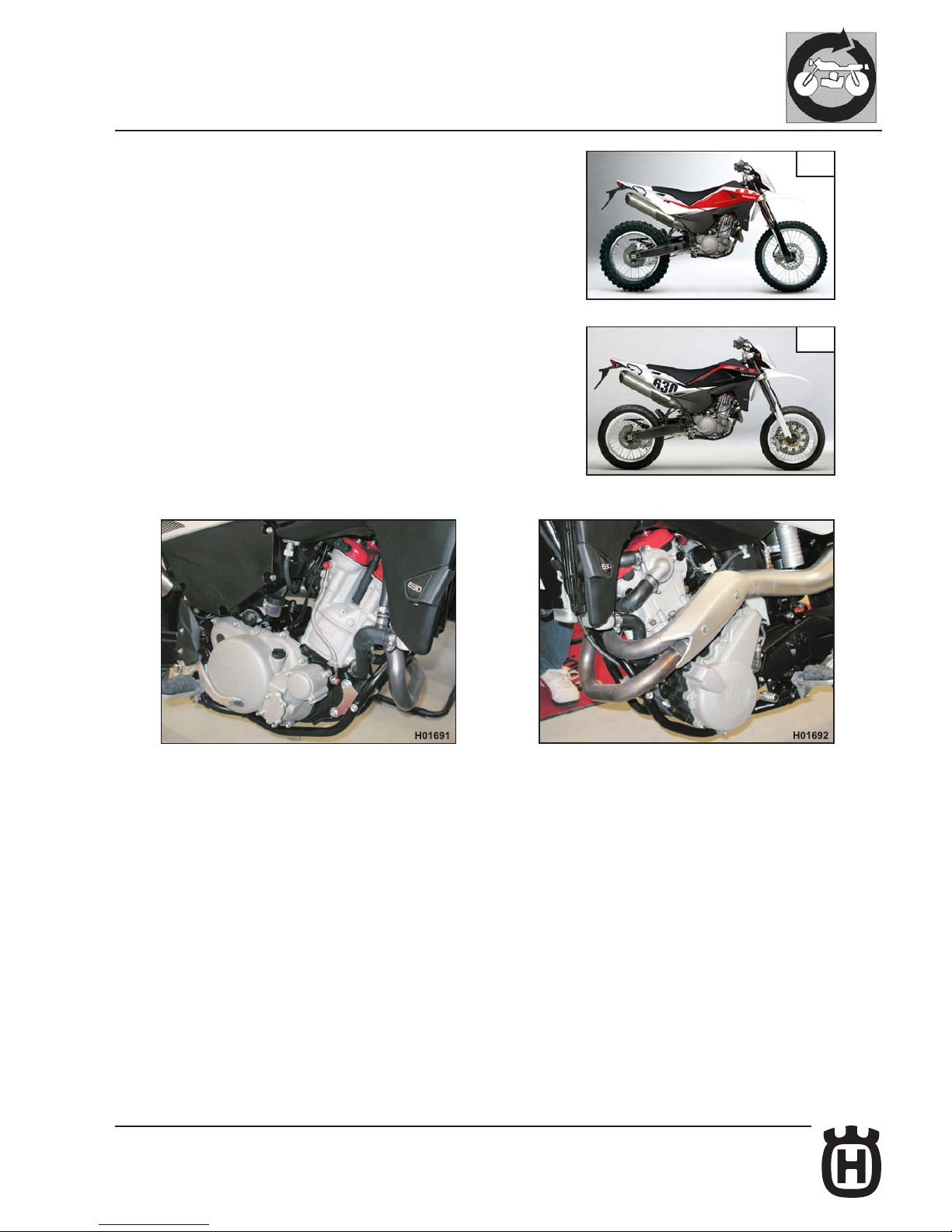
TE
SMS
GENERAL PROCEDURES
Foreword
This section describes the operations preliminary to engine removal.
Please note that, in order to gain access to certain motorcycle components (rear
shock absorber, electrical parts, wiring, etc.), it may be necessary to partially
remove some parts.
RIGHT-HAND SIDE LEFT-HAND SIDE
Page 62
E.4 Part. N. 8000 H2051 (02-2010)
GENERAL PROCEDURES
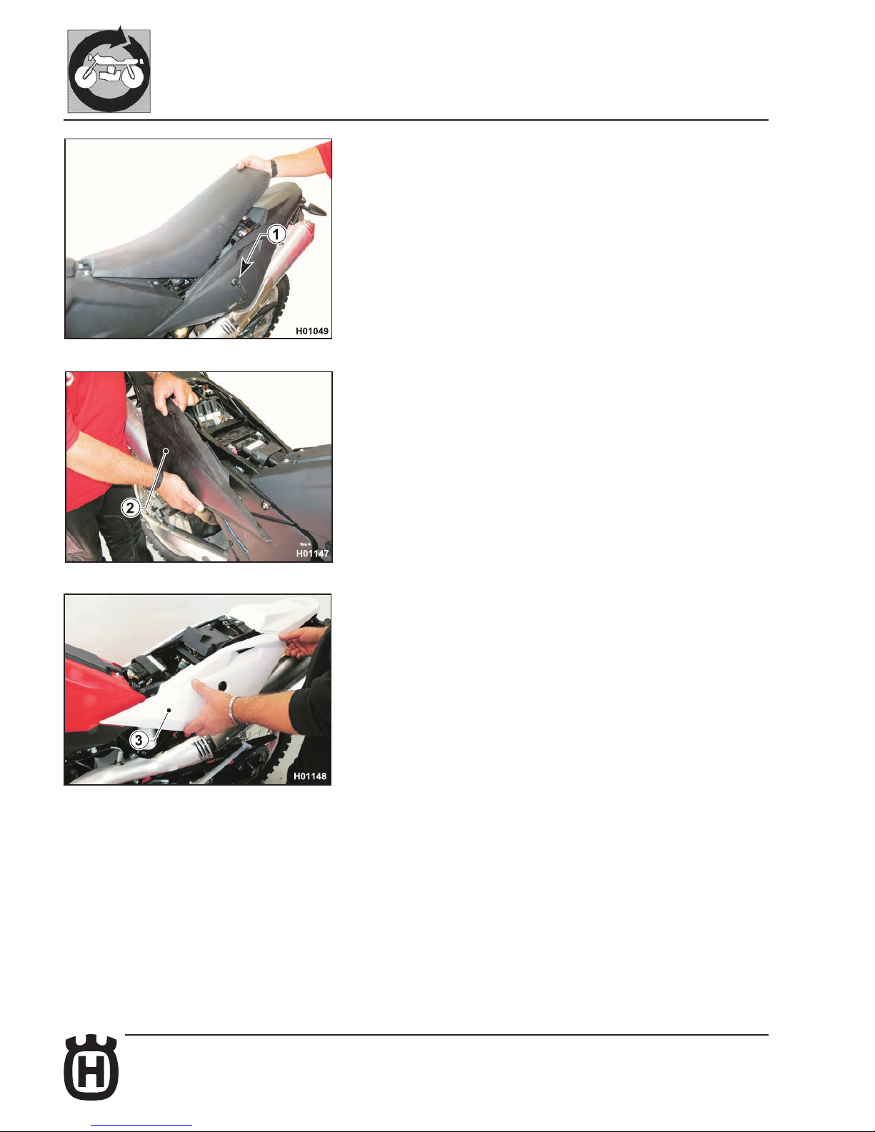
Saddle removal
- Insert the key in latch (1) then turn clockwise to release the saddle lock;
remove the saddle.
Side panel removal
- Remove the saddle as described in the relevant paragraph.
- Disengage rear side panels (2) and (3) then slide them toward vehicle
front.
Page 63
E.5Part. N. 8000 H2051 (02-2010)
GENERAL PROCEDURES
Battery removal
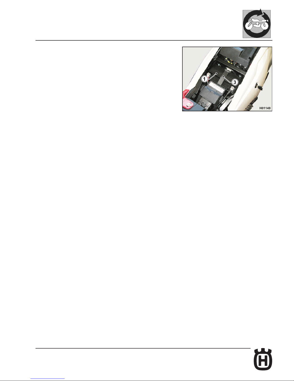
- Remove the saddle as described in the relevant paragraph.
- Release the elastic strap (3) holding the battery.
- First remove the BLACK negative cable (8 mm Allen wrench),
then the RED positive cable (when reassembling, rst connect
the RED positive cable, then the BLACK negative cable); remove
the battery (1) from its housing.
Page 64
E.6 Part. N. 8000 H2051 (02-2010)
10
9
8
8
3
3
5
5
3
4
4
4
4
3
3
3
10
2
11
7
1
6
2
2
H006005
GENERAL PROCEDURES
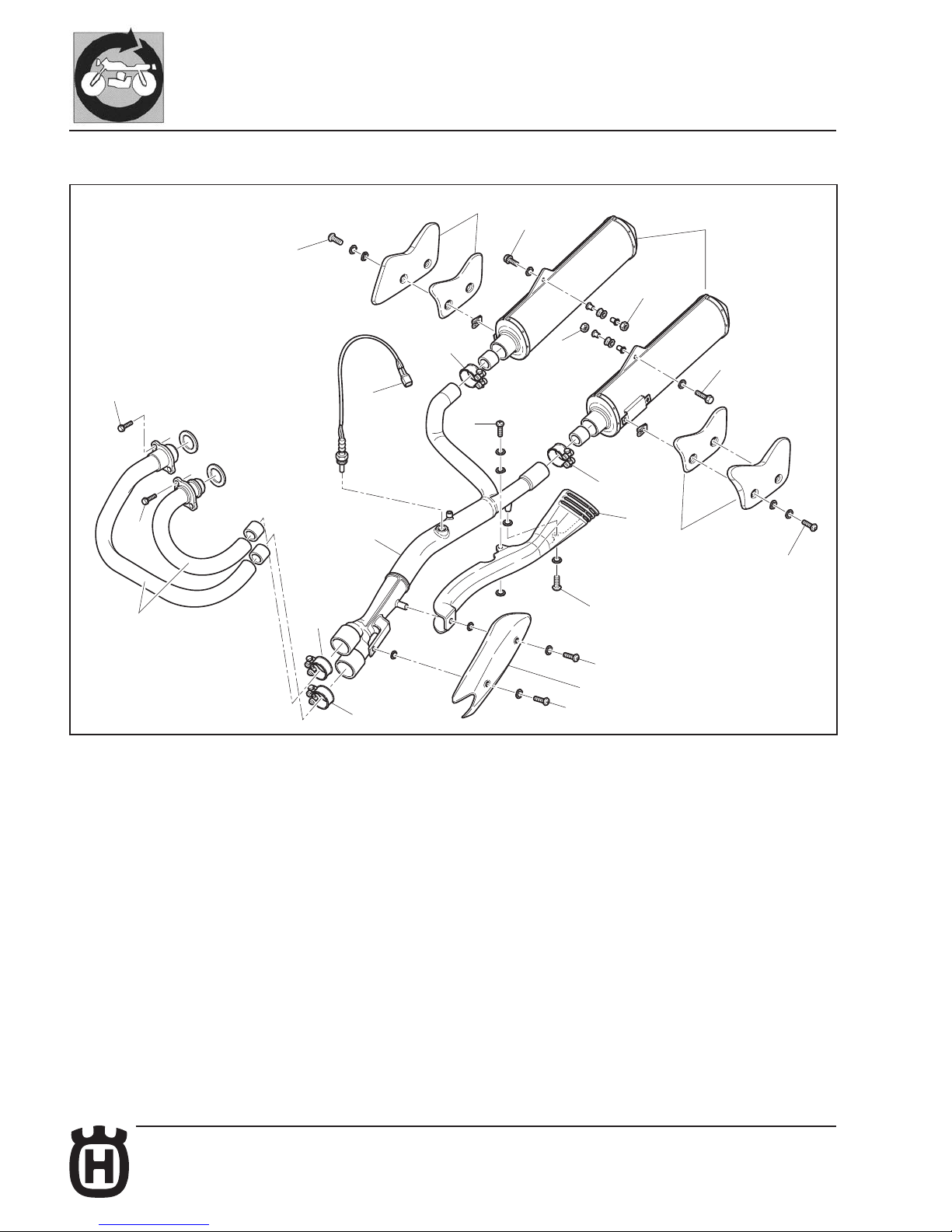
Exhaust system removal
Page 65
E.7Part. N. 8000 H2051 (02-2010)
3
2
3
2
H006006
GENERAL PROCEDURES
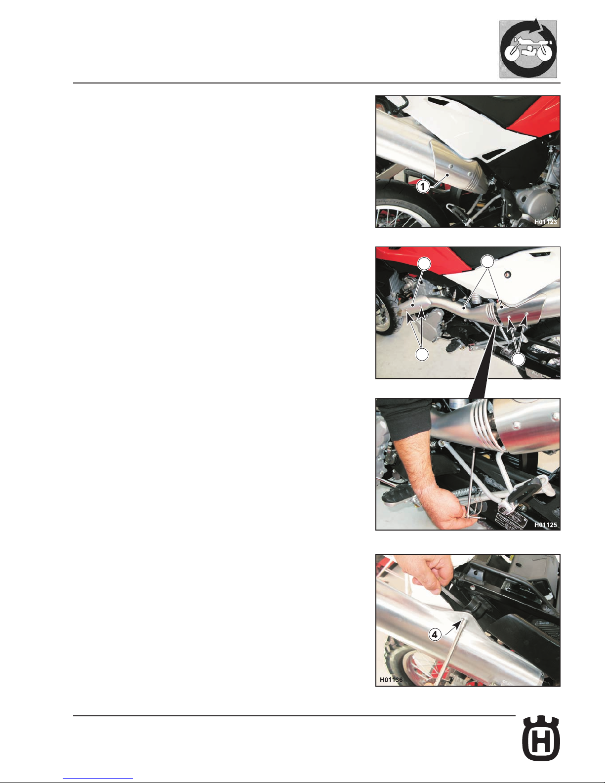
- Remove R.H. guard (1) and L.H. guards (2) loosening the screws (3) with a
4 mm Allen wrench.
- Remove saddle and side panels as described in the relevant paragraph.
- Loosen the screws (4) securing silencers to rear chassis using an 8 mm ring
wrench on the outside and a 10 mm ring wrench on the inside.
Page 66
E.8 Part. N. 8000 H2051 (02-2010)
H006007
6
H006008
GENERAL PROCEDURES
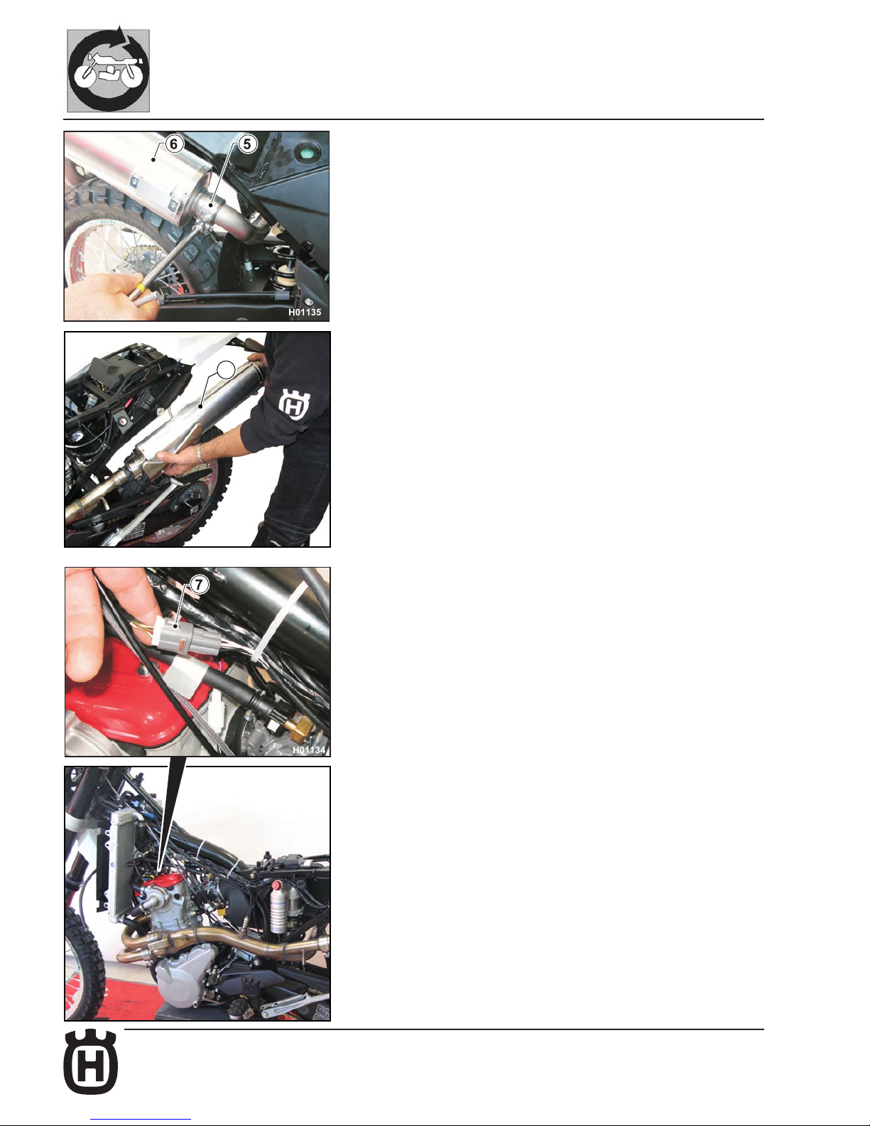
- Loosen metal clip (5) using a 13 mm wrench and remove the silencers (6).
- Disconnect the Lambda sensor connector (7).
Page 67
E.9Part. N. 8000 H2051 (02-2010)
H006009
11
GENERAL PROCEDURES
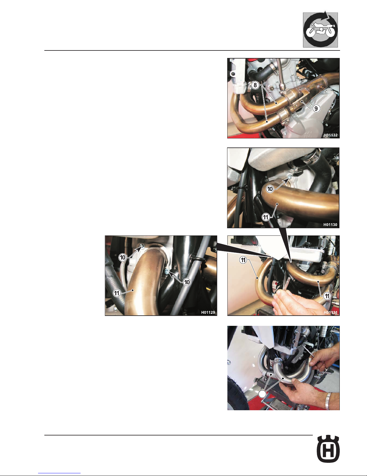
- Loosen the two clamps (8) using a 13 mm ring wrench and remove the central
pipe (9).
- Loosen the four screws (10) of the exhaust manifolds (11) using a 4 mm Allen
wrench and remove the manifolds with their rings.
Page 68
E.10 Part. N. 8000 H2051 (02-2010)
GENERAL PROCEDURES
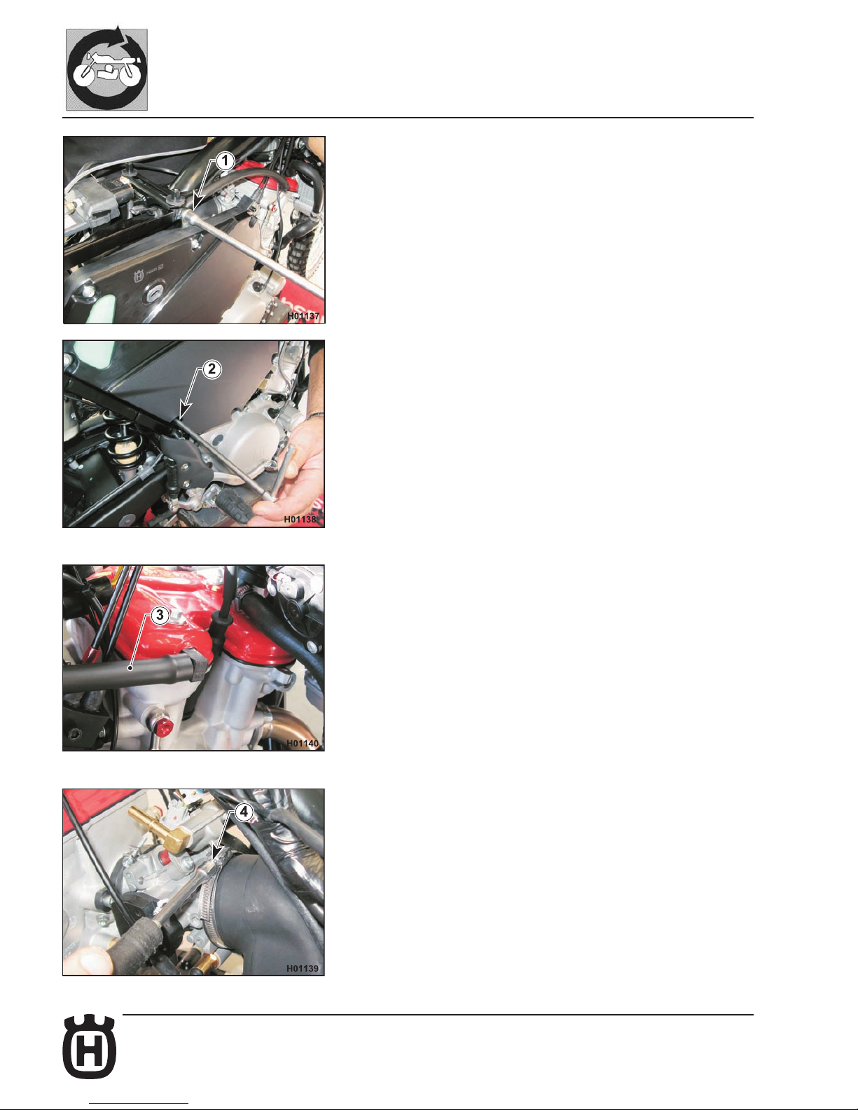
Air box removal
- Remove saddle, right-hand side panel and tank as outlined in the relevant
paragraphs.
- Loosen the upper locking nut (1) using a 12 mm ring wrench.
- Loosen the lower screw (2) securing air box to chassis using an 8 mm ring
wrench.
- Remove the hose (3) connecting lter to head.
- Move to the left side of the motorcycle and loosen clamp (4) that secures
lter to throttle body; use a 7 mm ring wrench.
Page 69
E.11Part. N. 8000 H2051 (02-2010)
GENERAL PROCEDURES
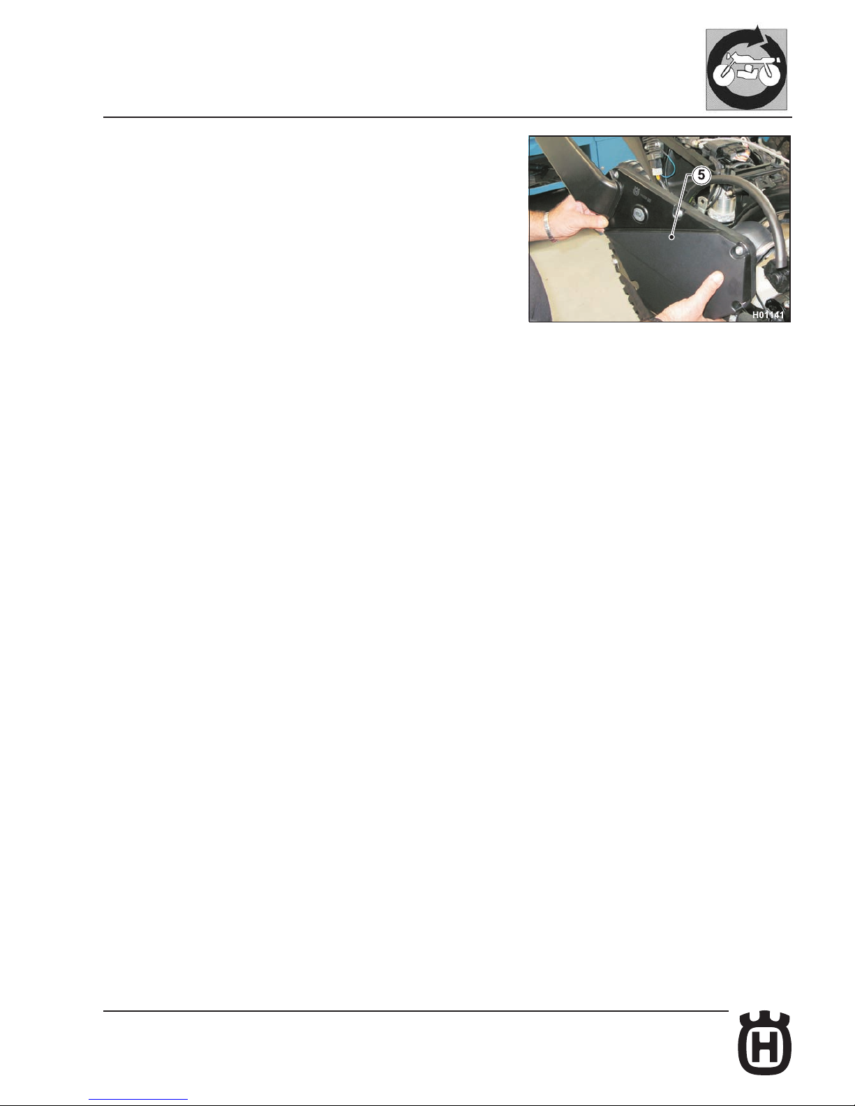
- Remove the complete air box (5) easing it off in rear to front motion.
Page 70
E.12 Part. N. 8000 H2051 (02-2010)
GENERAL PROCEDURES
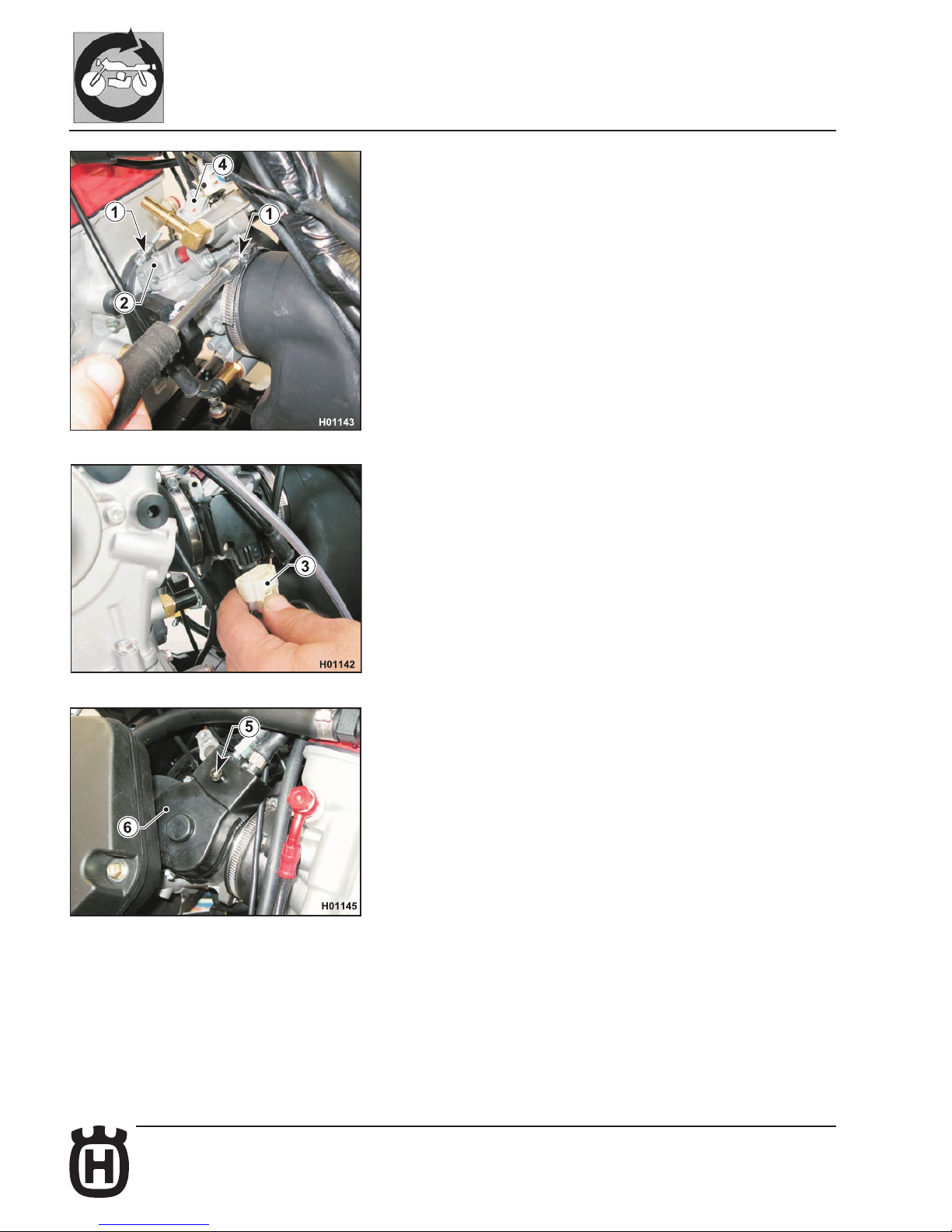
Throttle body removal
- Remove tank, saddle and left-hand side panel as outlined in the relevant
paragraphs.
- Loosen the clamps (1) securing throttle body (2) to air box hose coupling and
head.
- Disconnect the M.A.Q.S. sensor connector (3) from the throttle body.
- Disconnect the wiring harness connector (4) from the throttle body.
- Loosen screw (5) and remove the cover (6).
Page 71
E.13Part. N. 8000 H2051 (02-2010)
GENERAL PROCEDURES
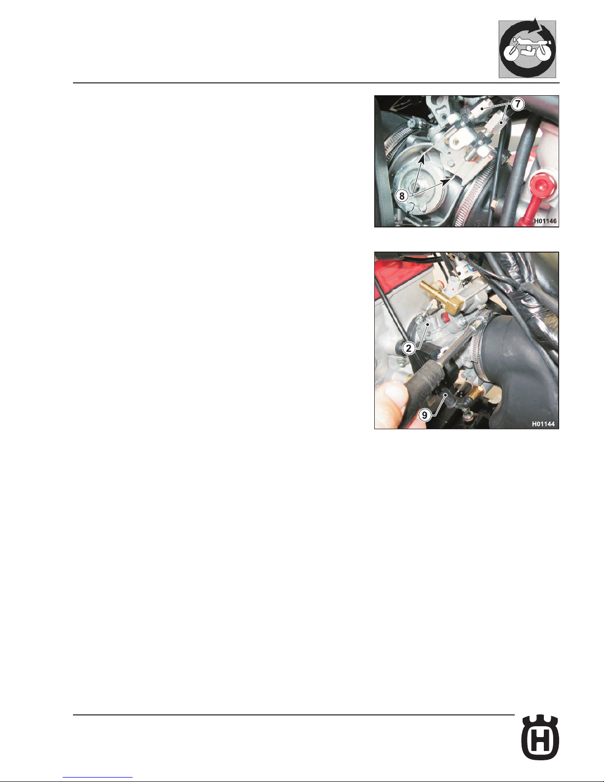
- Slacken adjusters (7) and disconnect the throttle cables (8).
- Remove the starter cable (9).
- Remove the throttle body (2); on assembly, adjust the throttle cable as outlined
in “Section D”.
Page 72
E.14 Part. N. 8000 H2051 (02-2010)
GENERAL PROCEDURES
Removing the rear chassis complete with mudguard
- Remove fuel tank, saddle, side panels, battery, air box, silencers and central
exhaust pipe as outlined in the relevant paragraphs.
- Shear the plastic clips securing main wiring harness.
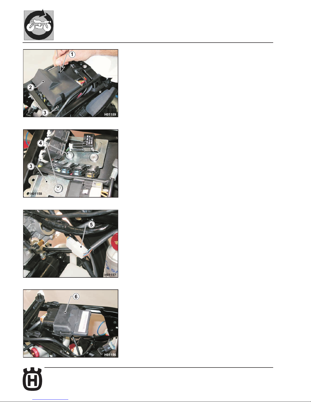
- Use a 3 mm Allen wrench to loosen the screw (1) and remove the cover (2)
of the utilities holder plate (3).
- Loosen the two screws (4) of the utilities holder plate (3).
- Disconnect the connector (5) of the rear wiring harness.
- Disconnect the electronic control unit (6) complete with exible mounting
from the rear chassis.
Page 73
E.15Part. N. 8000 H2051 (02-2010)
GENERAL PROCEDURES
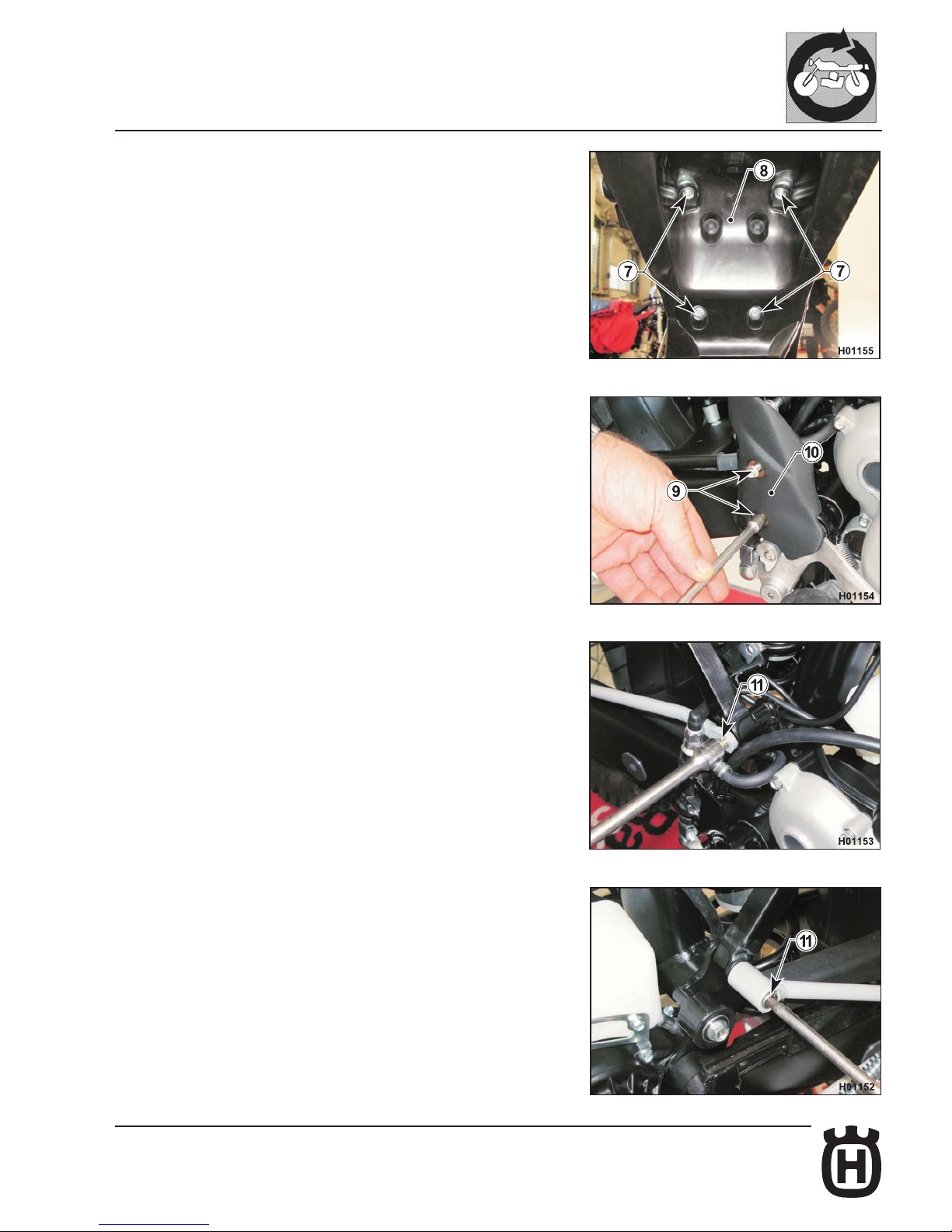
- Loosen the four screws (7) of the internal mudguard (8) using an 8 mm Allen
wrench.
- Push down the internal mudguard (8) and then slide the utilities holder plate
(3) toward vehicle front to remove it.
- Loosen the two screws (9) and remove the rear brake master cylinder cover
(10).
- Loosen the screws (11) securing footpegs and rear chassis to chassis (6 mm
Allen wrench).
Page 74
E.16 Part. N. 8000 H2051 (02-2010)
H006010
15
14
GENERAL PROCEDURES
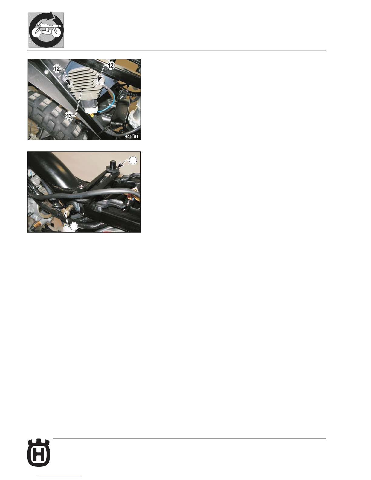
- Loosen the two nuts (12) of the voltage regulator (13) and remove it.
- Unscrew the top locking nut (14), extract the pin (15) and remove the rear
chassis sliding it toward the rear end of the vehicle.
Page 75
E.17Part. N. 8000 H2051 (02-2010)
GENERAL PROCEDURES
Fuel tank removal
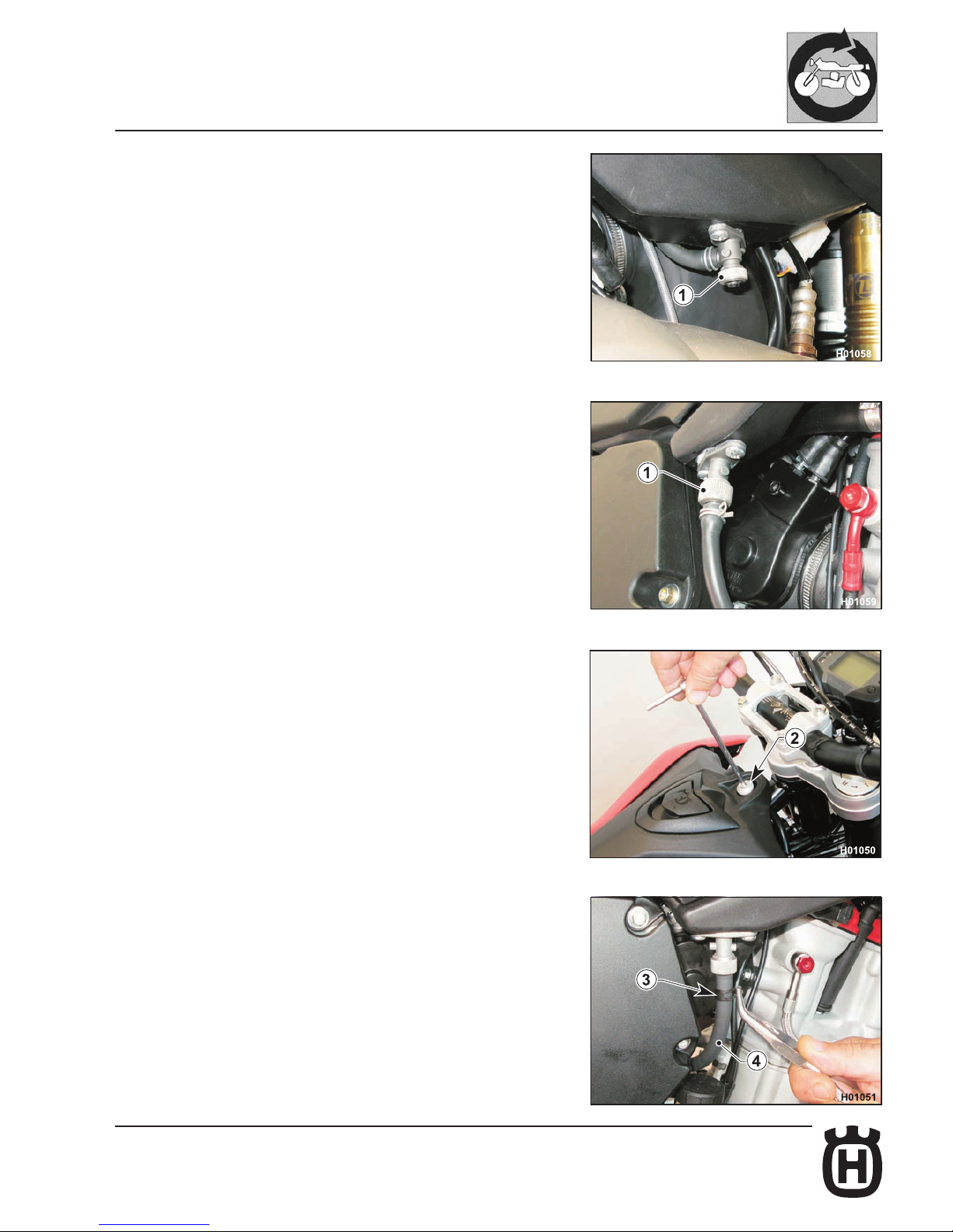
- Remove the saddle as described in the relevant paragraph.
- Close both fuel cocks (1)
- Use a 6 mm Allen wrench to loosen the screw (2) and remove the screw with
its spacer.
- Place a vessel under the R.H. cock to collect fuel.
- Loosen clamp (3) and disconnect tube (4) from the fuel cock. Let the fuel
drain out.
Page 76
E.18 Part. N. 8000 H2051 (02-2010)
GENERAL PROCEDURES
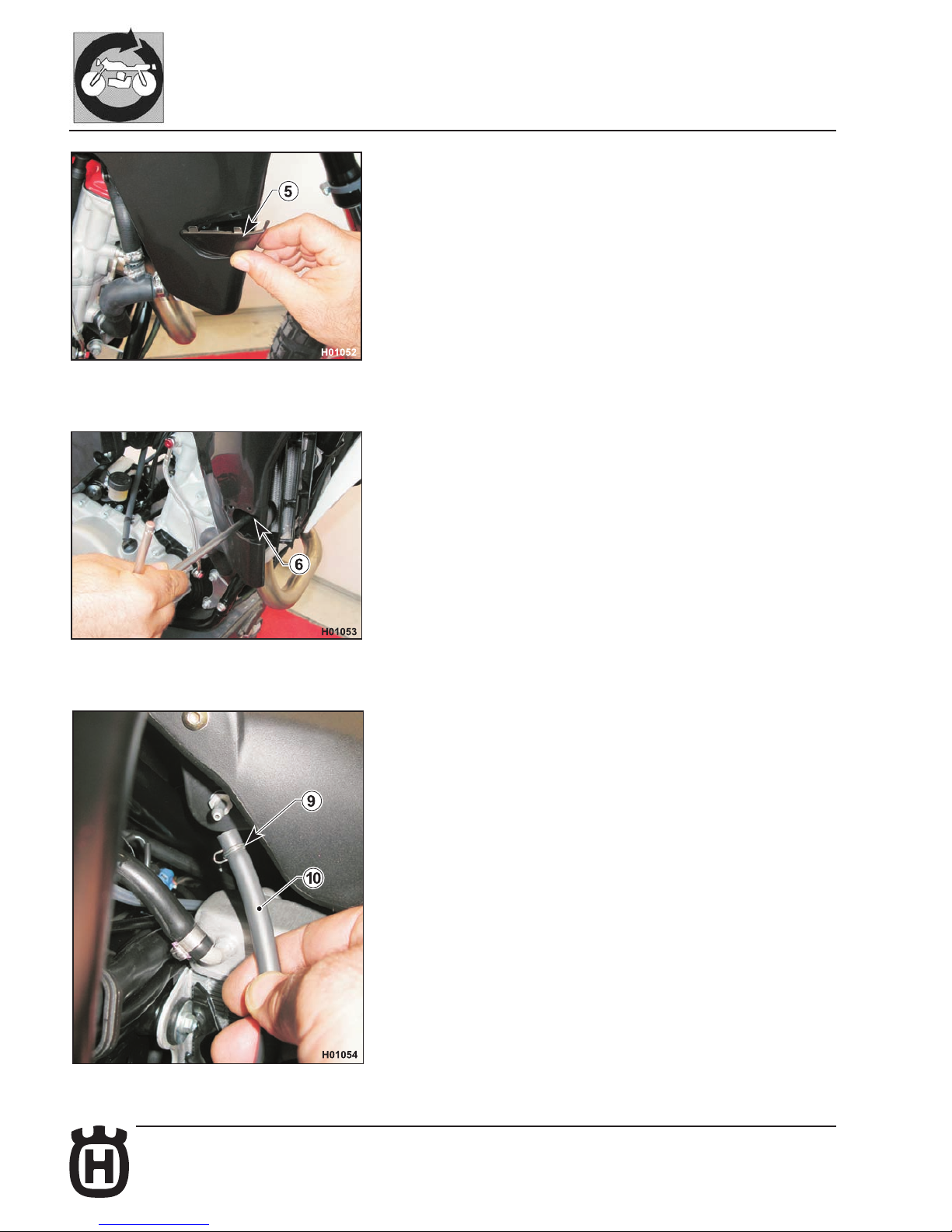
- Remove the covers (5) located on the R.H. and L.H. side of the tank.
- Loosen the screws (6) using an 8 mm wrench.
- Move to the left side of the tank, slacken clamp (9) and disconnect the breather hose (10).
Page 77
E.19Part. N. 8000 H2051 (02-2010)
GENERAL PROCEDURES
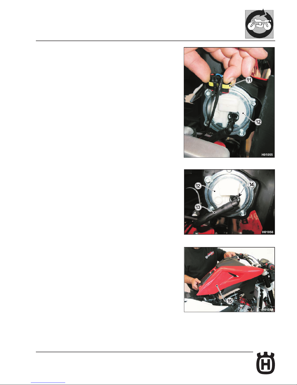
- Raise the tank from the front end and disconnect the fuel pump (12) connector
(11).
- Disconnect the hose (13) connecting tank to throttle body; press down the
ring (14) and disconnect hose (13) from pump (12).
- Raise the tank (15) and remove it together with the scoops.
- Reassemble all parts in the reverse order compared to disassembly and
tighten screws to the specied torque (see Section X)
Page 78
E.20 Part. N. 8000 H2051 (02-2010)
1
2
H01160
GENERAL PROCEDURES
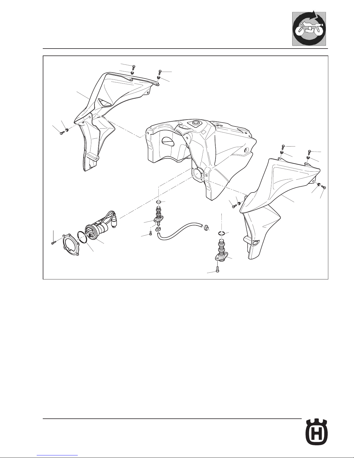
Fuel tank disassembly (scoops and fuel pump)
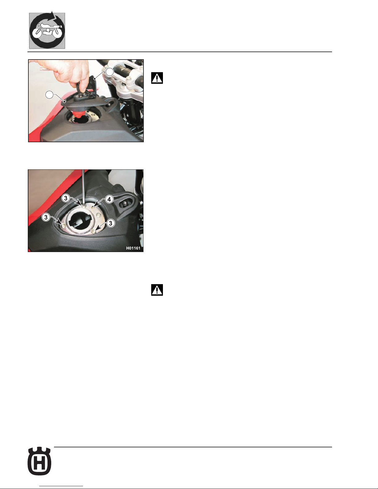
Before disassembling the tank, open both fuel cocks and drain it
completely.
- Remove the fuel tank as described in the relevant paragraph.
- Raise the cover (1), insert the key, turn it and remove the cap (2).
- Use a 3 mm Allen wrench to loosen the M5 screws (3) and a 4 mm Allen
wrench to loosen the M6 screw (4); then remove the fuel cap ange.
- Loosen the screws (7) using an 8 mm ring wrench and remove right (5) and
left scoops (6).
On assembly, make sure the bushings (8) are correctly positio-
ned in the scoops before tightening the screws (7).
- Loosen the screws (9) using an 8 mm ring wrench and remove the fuel pump
(10)
IMPORTANT: Make sure to position gasket (11) correctly on assembly.
- Use a screwdriver to loosen the screws (12) and remove the cocks (13).
IMPORTANT: Make sure to position gaskets (14) correctly when retting the
cocks.
- Reassemble all parts in the reverse order compared to disassembly and
tighten screws to the specied torque (see Section X)
Page 79
E.21Part. N. 8000 H2051 (02-2010)
H01162
7
8
5
9
7
8
7
8
7
8
7
8
6
7
8
14
12
14
12
7
8
10
11
13
14
13
GENERAL PROCEDURES
Page 80
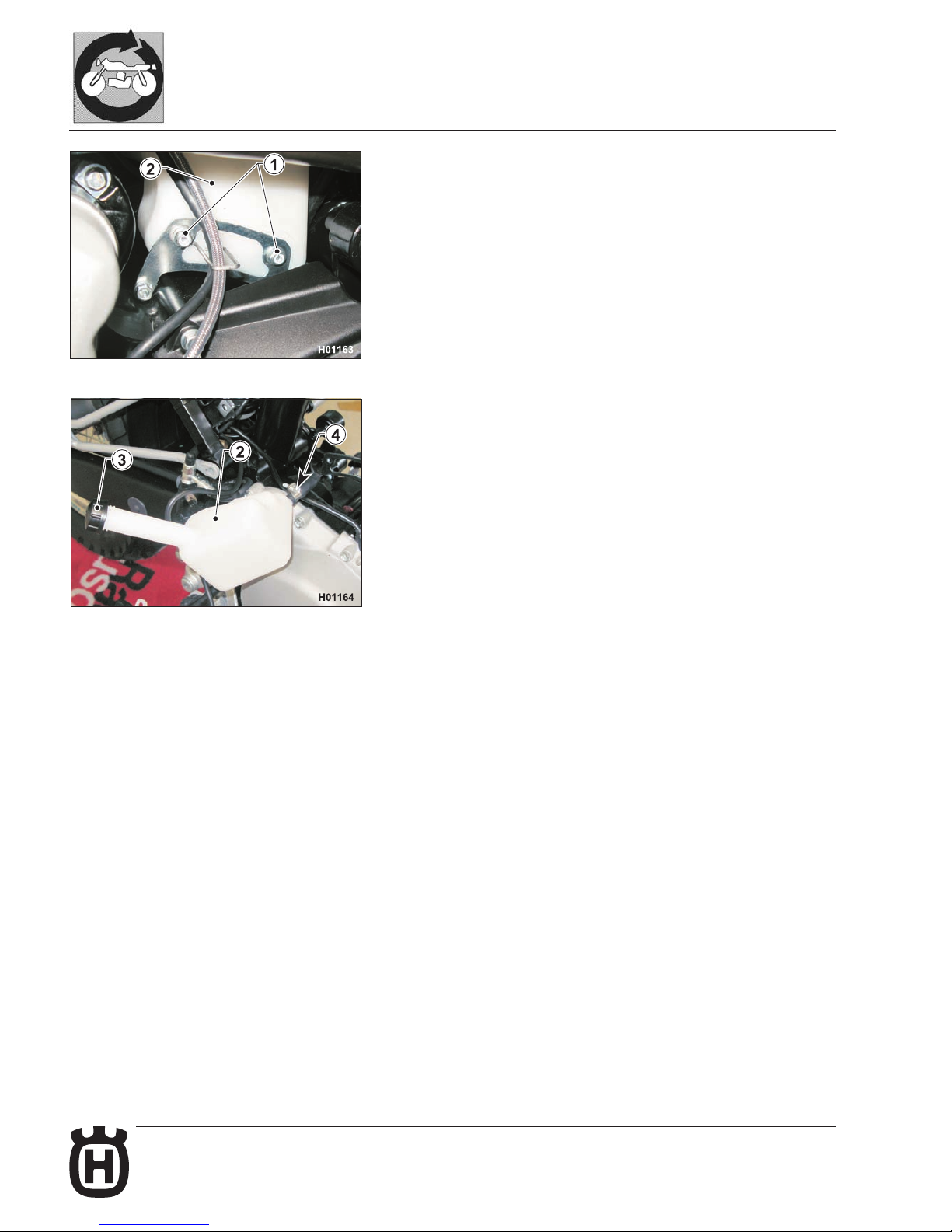
E.22 Part. N. 8000 H2051 (02-2010)
GENERAL PROCEDURES
Expansion tank removal
- Remove fuel tank, saddle, right-hand side panel and air box as outlined in
the relevant paragraphs.
- Loosen the two upper retaining screws (1) of the expansion tank (2) on the
left side of the motorcycle.
- Disconnect breather hose from radiator cap.
- Remove the expansion tank (2) from the right side of the motorcycle.
- Remove the cap (3) and drain all uid.
- Loosen the clamp (4) and disconnect the breather hose.
Page 81
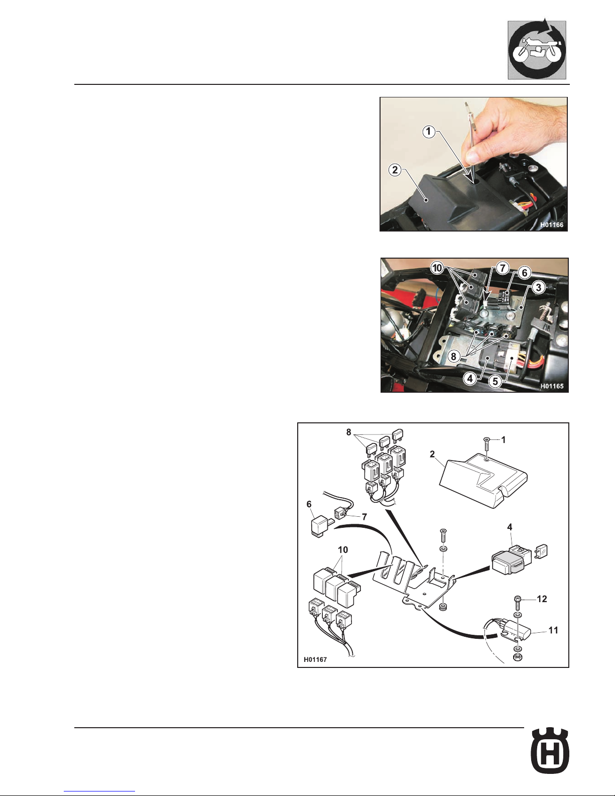
E.23Part. N. 8000 H2051 (02-2010)
GENERAL PROCEDURES
Removing utilities (solenoid starter, relays, fuses, asher)
- Remove the saddle as described in the relevant paragraph.
- Loosen screw (1) and remove the cover (2).
- The utilities holder plate (3) holds:
4) Solenoid starter; disconnect connector (5) and remove solenoid starter
from plate with its exible mount.
6) Flasher; release it from its seat and disconnect the connector (7).
8) Fuses; take off the protection cap (9) and remove the blade fuses.
10) Relays; release the fuses from their seat and remove them with the
exible mount, then remove the connector.
11) Rollover sensor (SMS only); loosen the two screws (12) to remove it.
Page 82
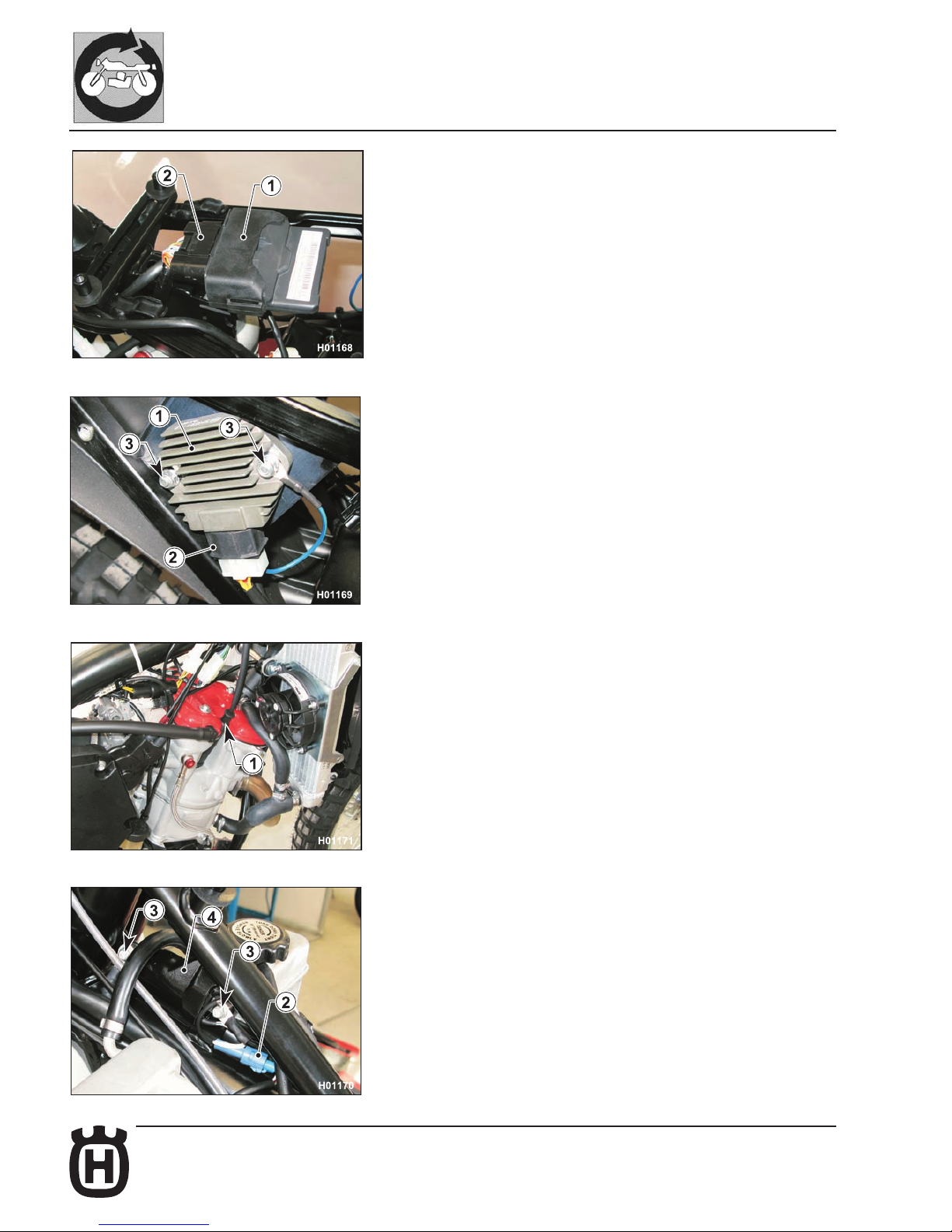
E.24 Part. N. 8000 H2051 (02-2010)
GENERAL PROCEDURES
Electronic control unit removal
- Remove the saddle as described in the relevant paragraph.
- Raise the electronic control unit (1) with its exible mount and detach it from
the rear chassis.
- Disconnect the connector (2).
Voltage regulator removal.
- Remove saddle, right-hand side panel and air box cover as outlined in the
relevant paragraphs.
- Loosen the two screws (1), disconnect the connector (2) and remove the
voltage regulator (3).
Ignition coil removal
- Remove: saddle and fuel tank as described in the relevant paragraphs.
- Remove the spark plug cap (1).
- Disconnect the connector (2).
Page 83
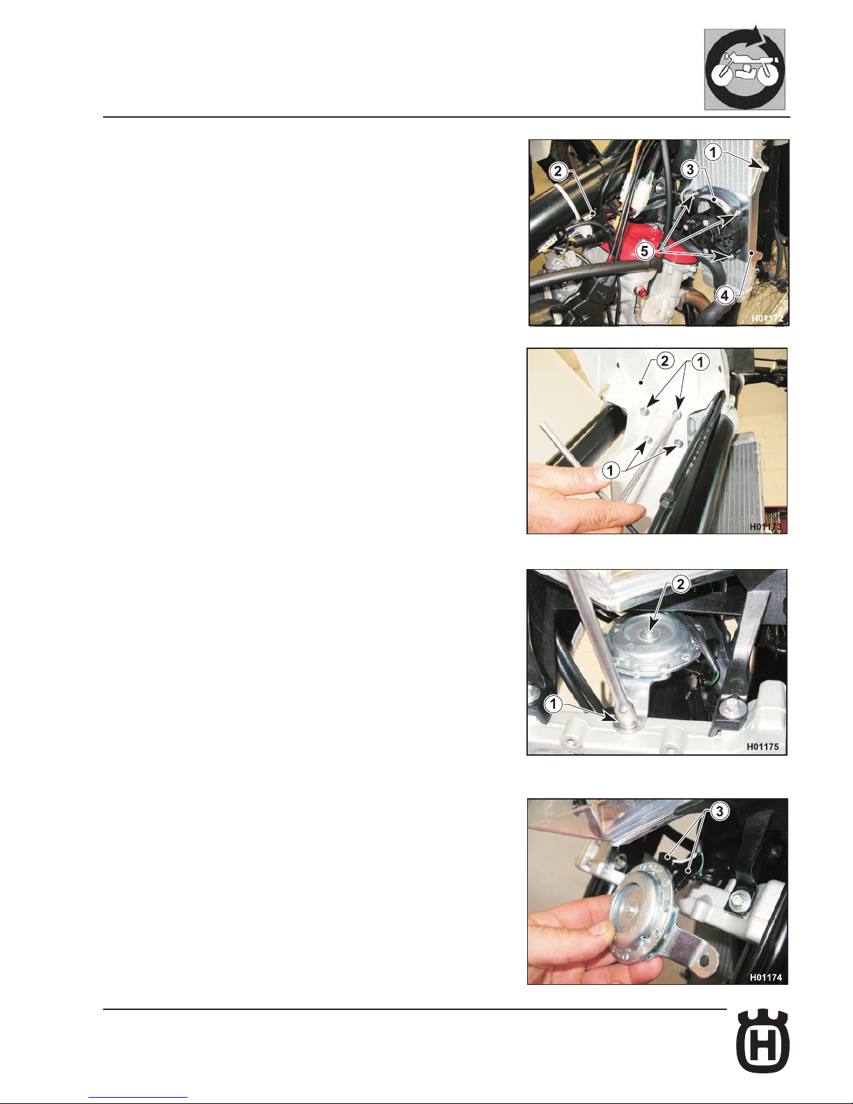
E.25Part. N. 8000 H2051 (02-2010)
GENERAL PROCEDURES
- Remove the retaining screws (3) and then the coil (4).
Electric cooling fan removal
- Remove saddle and tank as outlined in the relevant paragraphs.
- Loosen screw (1) and remove the connector (2).
- Remove the electric fan (3) together with its bracket (4).
- Loosen the three screws (5) using a 7 mm wrench and take the electric fan
(3) off the bracket (4).
Front mudguard removal.
- Loosen the four screws (1) using an 8 mm ring wrench and remove the
mudguard (2).
Horn removal.
- Remove the front mudguard as described in the relevant paragraph.
- Loosen the retaining screw (1) of the horn (2) with an 8 mm ring wrench.
- Disconnect the two connectors (3).
Page 84
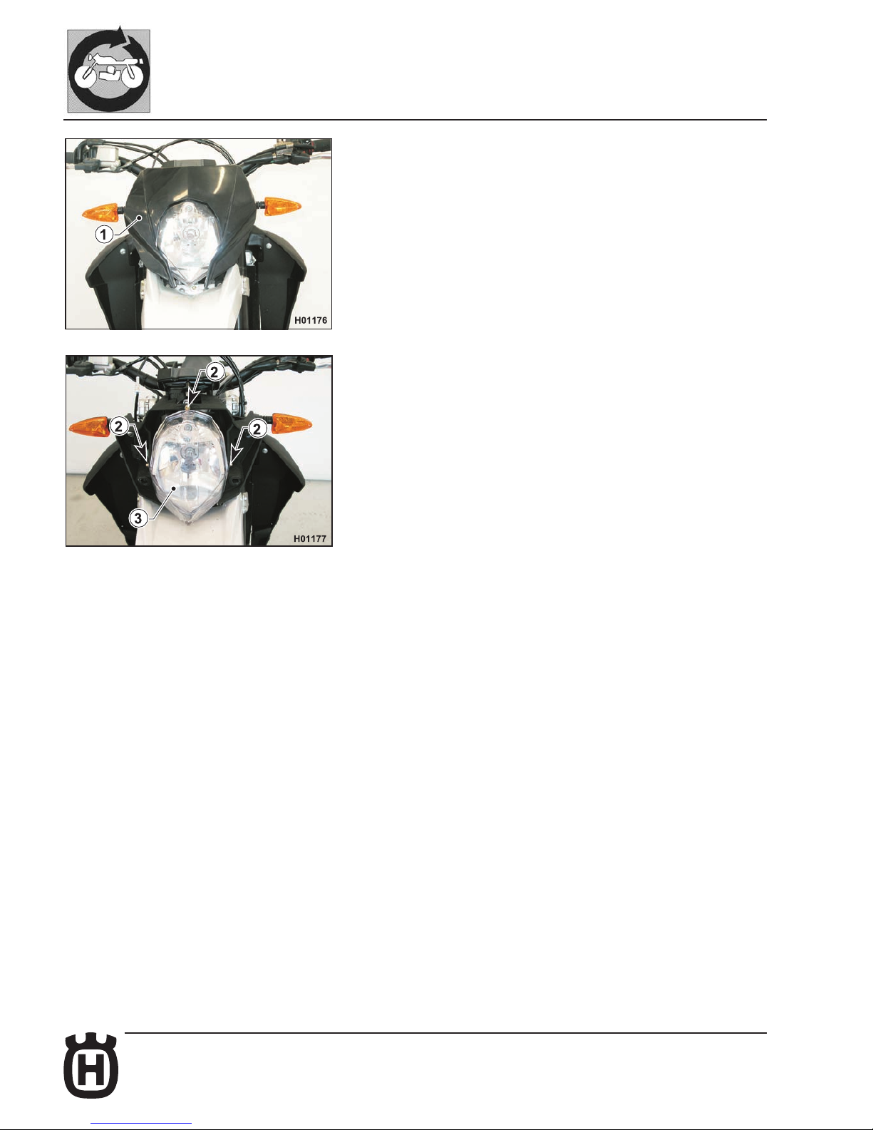
E.26 Part. N. 8000 H2051 (02-2010)
GENERAL PROCEDURES
Headlamp removal
Proceed as follows to reach the headlamp bulbs:
- pull out the front fairing (1) to remove it;
- loosen the three screws (2) and remove the headlamp (3);
Page 85
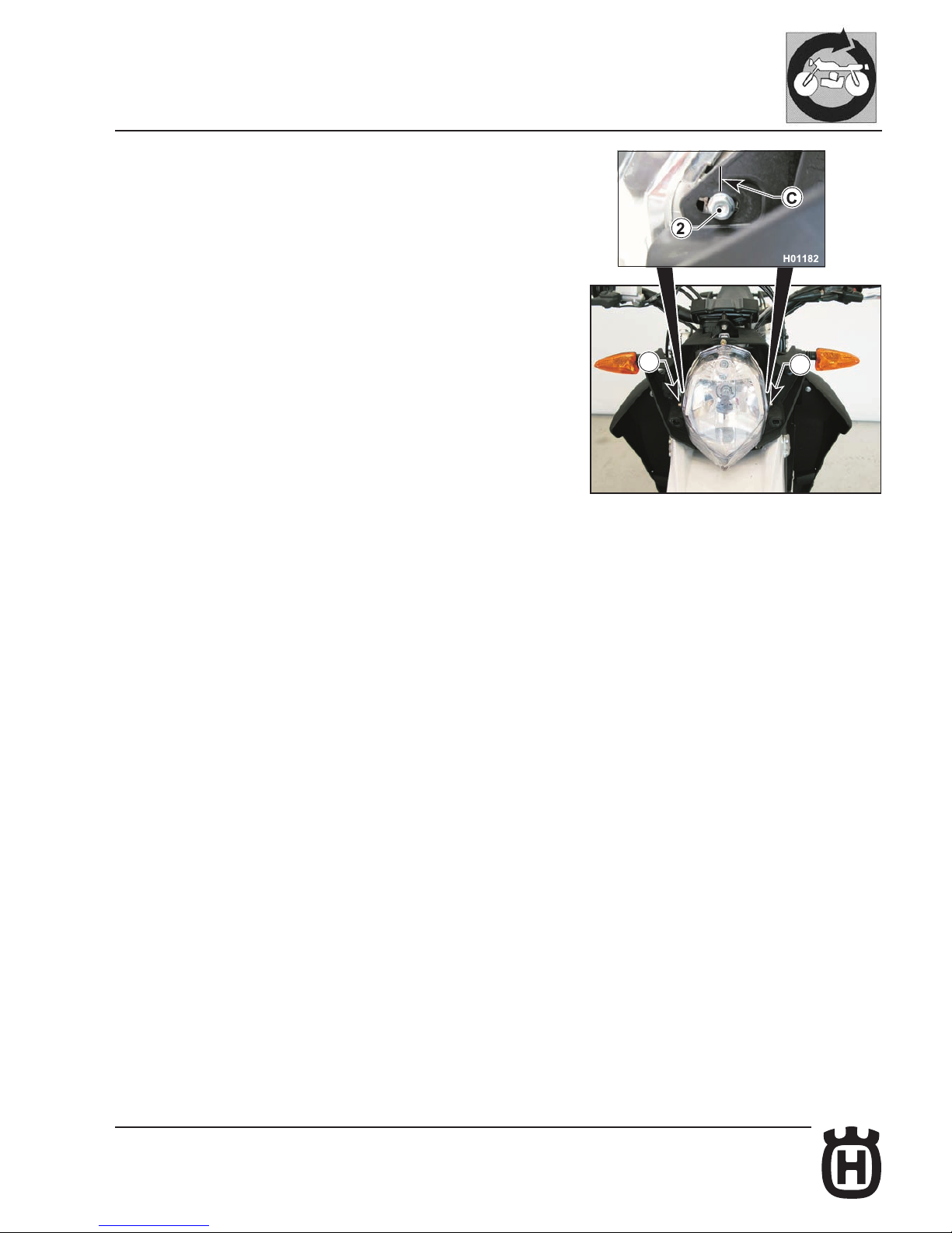
E.27Part. N. 8000 H2051 (02-2010)
H01177
2
2
GENERAL PROCEDURES
On assembly, make sure the midline of side screw heads (2) lines up with the
notch (C) on the support.
Page 86
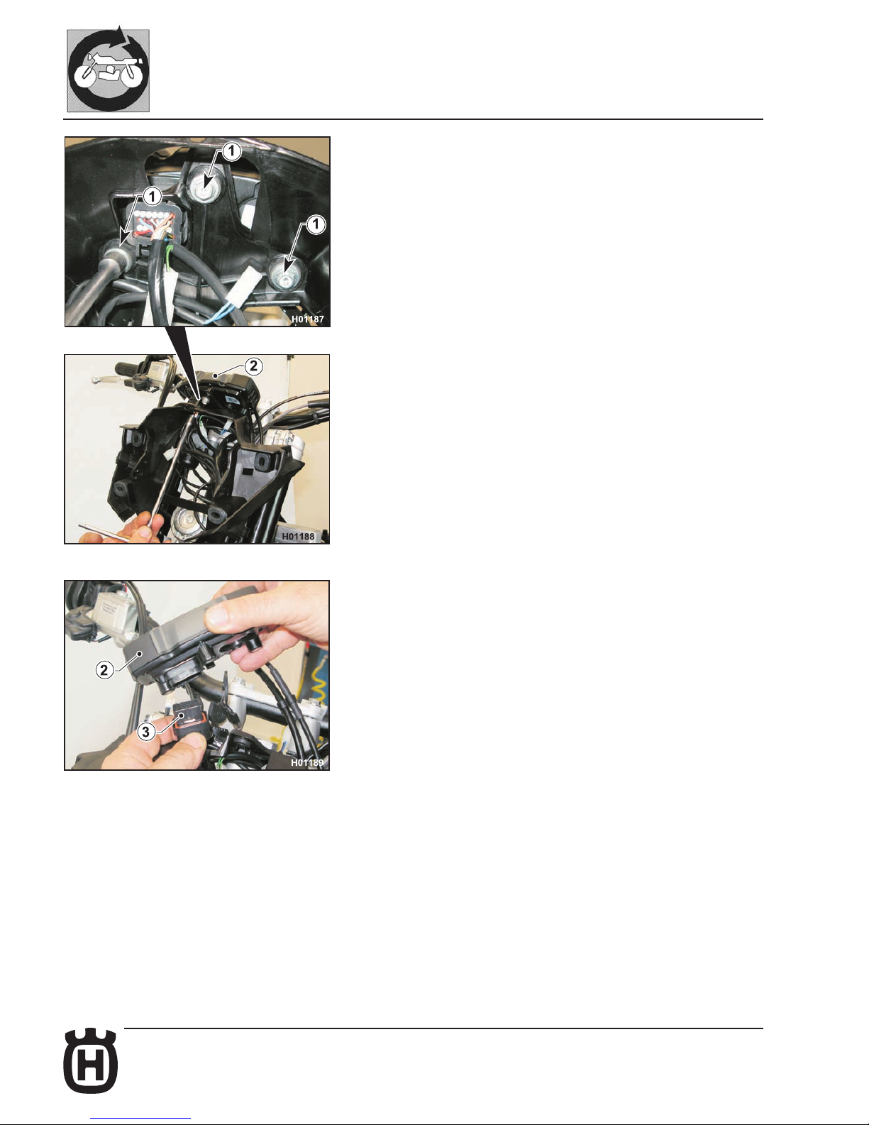
E.28 Part. N. 8000 H2051 (02-2010)
GENERAL PROCEDURES
Digital dashboard removal.
- Remove the headlamp as described in the relevant paragraph.
- Loosen the three screws (1) using an 8 mm ring wrench; be sure to collect
the spacers.
- Raise the dashboard (2) and disconnect the connector (3).
Page 87
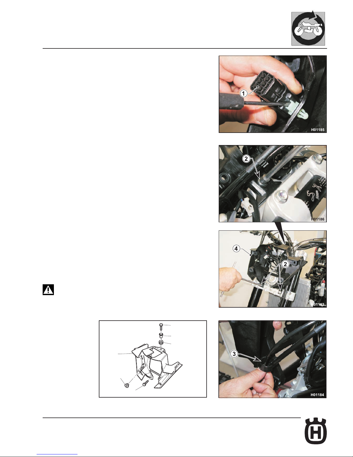
E.29Part. N. 8000 H2051 (02-2010)
H01190
4
6
2
5
2
6
GENERAL PROCEDURES
Headlamp fairing removal.
- Remove headlamp, front mudguard and digital dashboard as outlined in the
relevant paragraphs.
- Disconnect the diagnostic connector (1).
- Loosen the three screws (2) using an 8 mm ring wrench, open the clamp (3),
slip off brake and trip meter cables and remove headlamp fairing (4).
On assembly, make sure to position bushing (5) and rubbers (6)
correctly.
Page 88
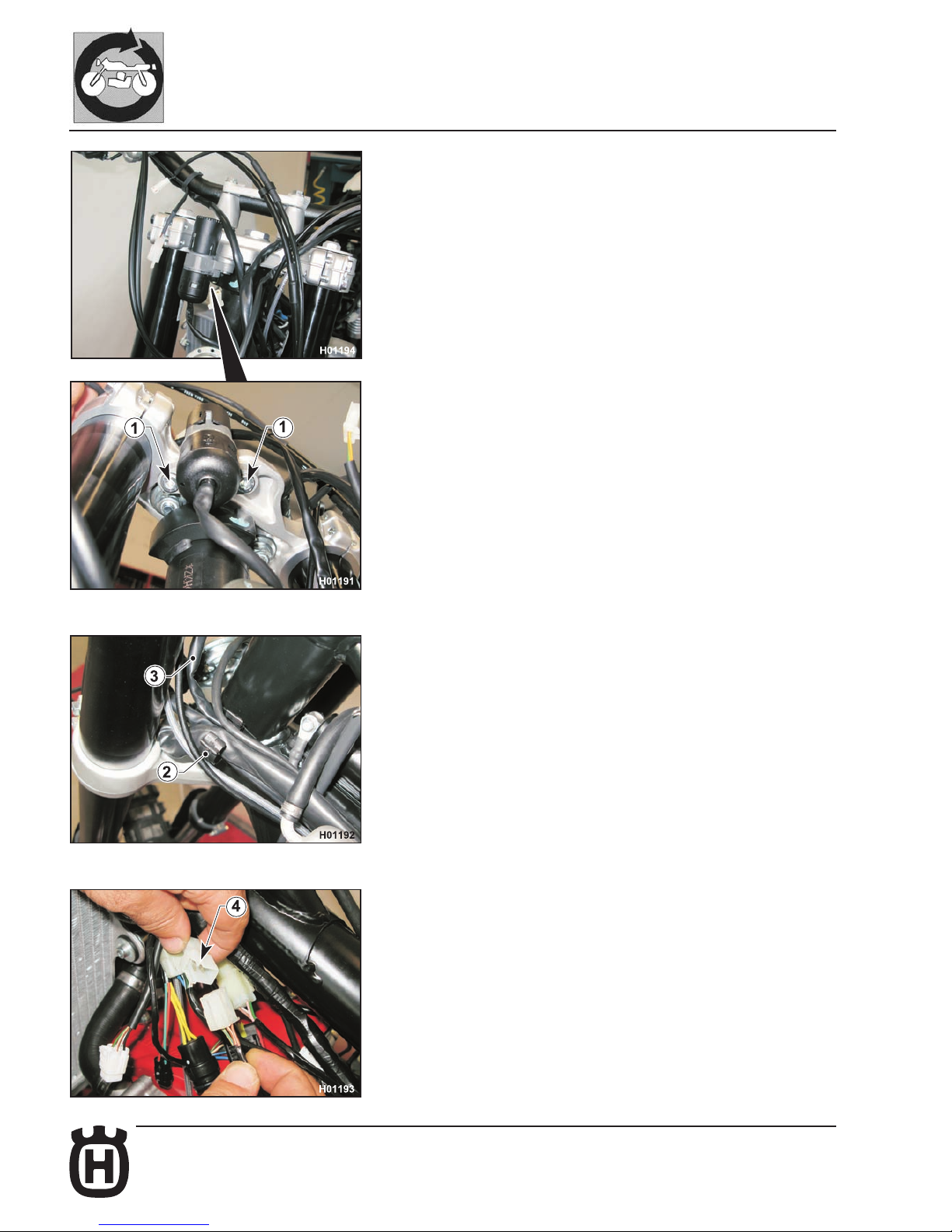
E.30 Part. N. 8000 H2051 (02-2010)
GENERAL PROCEDURES
Ignition switch removal.
- Remove headlamp fairing, saddle and tank as outlined in the relevant paragraphs.
- Loosen the two screws (1) using a 6 mm Allen wrench.
- Release the clamp (2) and slip off the cable (3).
- Disconnect the connector (4).
Page 89
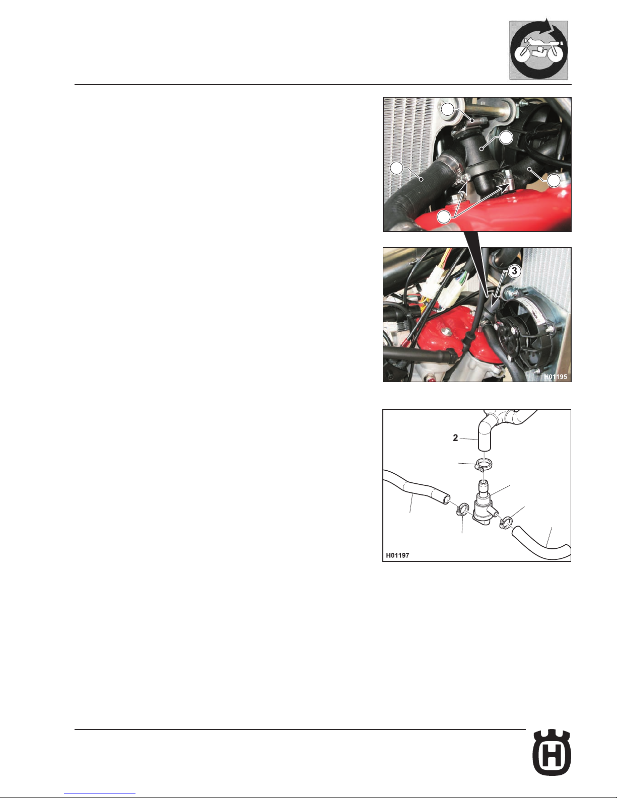
E.31Part. N. 8000 H2051 (02-2010)
1
3
1
2
1
2
H01196
2
2
1
3
1
GENERAL PROCEDURES
Thermal expansion valve removal.
- Remove saddle and tank as outlined in the relevant paragraphs.
- Drain coolant from the radiators as described in "Section D".
- Disconnect the three clamps (1), disconnect the hoses (2) from the thermal
expansion valve (3) and remove the valve.
NOTE: After retting the thermal expansion valve, ll with coolant as outlined
in “Section D”.
Page 90
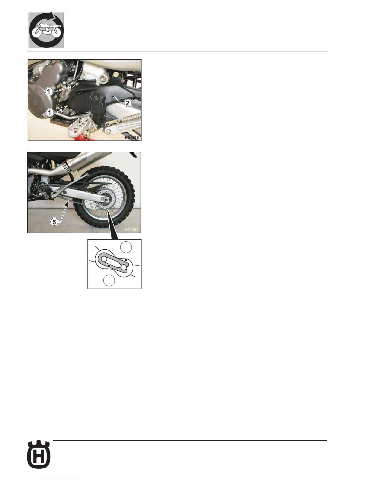
E.32 Part. N. 8000 H2051 (02-2010)
4
3
GENERAL PROCEDURES
Secondary drive chain removal
The following procedure applies to both O-ring chains and chains without Orings:
- Remove: screws (1), sprocket guard (2), clip (3), master link (4) and chain
(5).
NOTE: On assembly, follow the instructions given on the paragraph covering
the chain in Section "D".
Engine removal
- Remove the saddle as described in the relevant paragraph.
- Remove the side panels as described in the relevant paragraph.
- Remove the fuel tank as described in the relevant paragraph.
- Remove the exhaust system as described in the relevant paragraph.
- Remove the chain as described in the relevant paragraph.
- Drain coolant from the radiators as described in Section "D".
- Remove the air lter as described in the relevant paragraph.
- Remove the throttle body as described in the relevant paragraph.
- Remove the expansion tank as described in the relevant paragraph.
Page 91
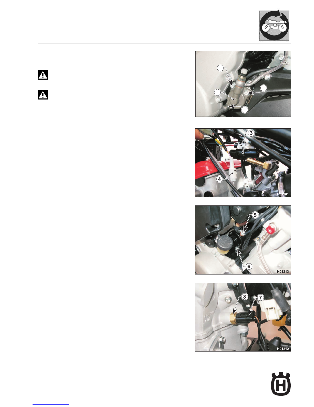
E.33Part. N. 8000 H2051 (02-2010)
H006011
2
1
1
1a
GENERAL PROCEDURES
- Loosen the two screws (1) and screw (1a) of the clutch actuator (2) using an
8 mm ring wrench and remove the actuator.
Make sure to ret screw (1a) in the original position on assem-
bly.
Make sure no one pulls the clutch lever with the actuator remo-
ved.
- Disconnect the two ignition connectors (3) and the gear sensor connector
(4).
- Loosen the screw (5) of the starter motor electric connection using a 10
mm ring wrench and loosen the ground cable screw (6) with an 8 mm ring
wrench.
- Disconnect the connector (7) from the temperature sensor (8).
Page 92
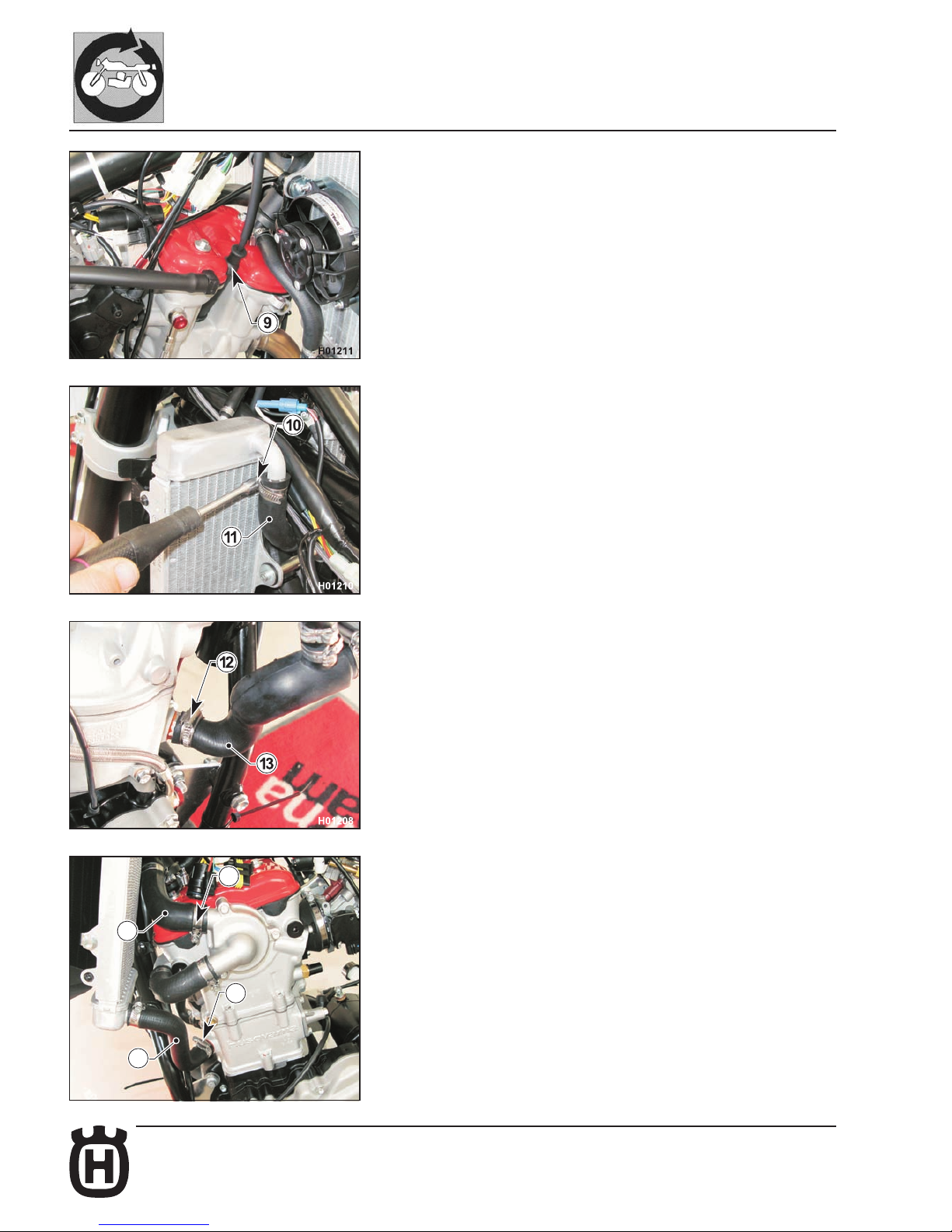
E.34 Part. N. 8000 H2051 (02-2010)
H006012
12
13
13
12
GENERAL PROCEDURES
- Take off the spark plug cap (9).
- Loosen the clamp (10) using a 7 mm ring wrench and disconnect the hose
(11) from the left-hand radiator to make room for the ignition connectors
(3).
- Loosen the clamps (12) using a 7 mm ring wrench and detach the hoses (13)
from the engine.
Page 93
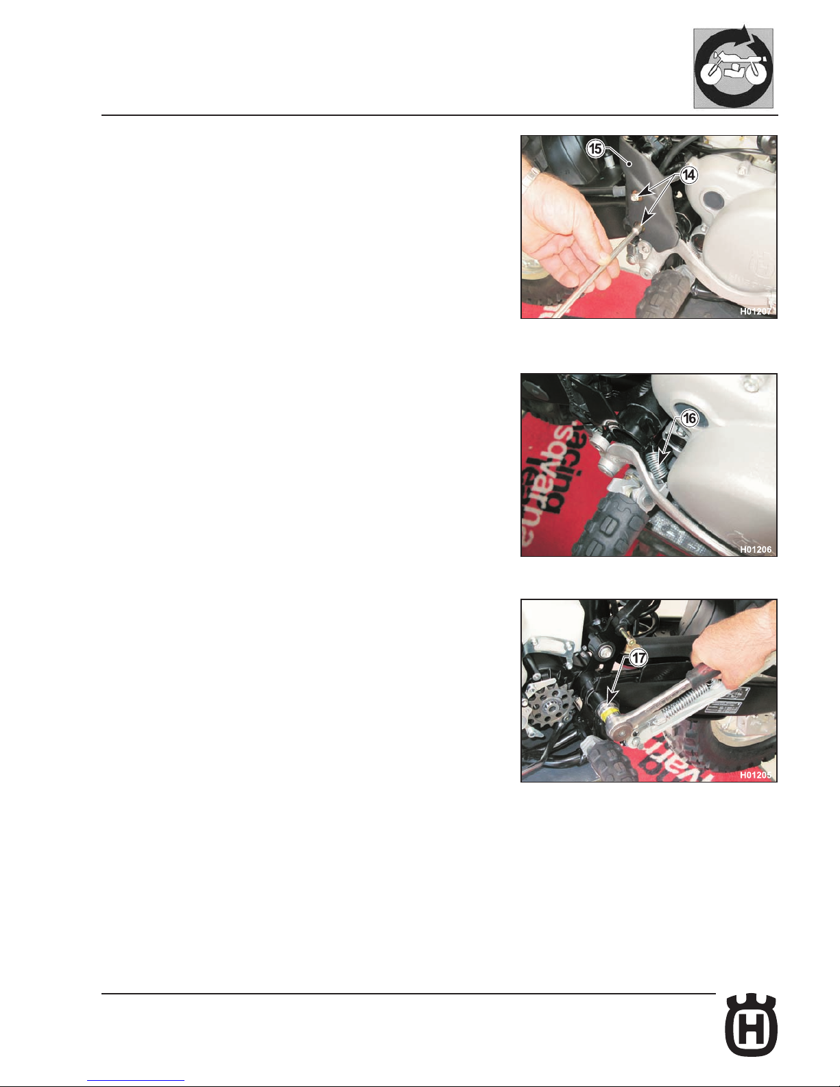
E.35Part. N. 8000 H2051 (02-2010)
GENERAL PROCEDURES
- Loosen the two screws (14) using an 8 mm ring wrench and remove the rear
brake master cylinder guard (15)
- Disengage the rear brake pedal return spring (16).
- Loosen the nut (17) of the rear engine mounting bolt using a 22 mm socket
wrench.
Page 94
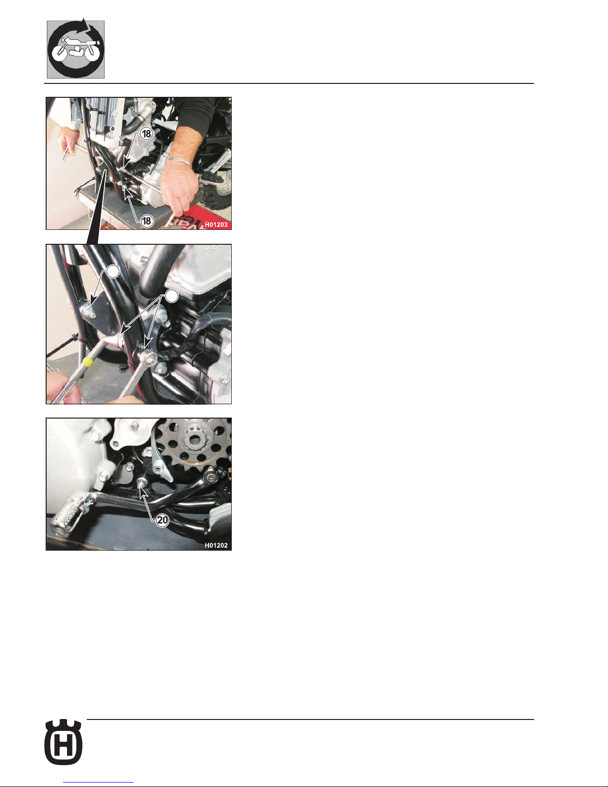
E.36 Part. N. 8000 H2051 (02-2010)
H006013
19
19
GENERAL PROCEDURES
- Loosen the nut of the front bolts (18) using a 10 mm ring wrench on the lefthand side and a 12 mm wrench on the right-hand side, but do not remove
the bolts.
- Loosen the bolts (19) of the engine front mounting brackets using two 12 mm
ring wrenches.
- Loosen the nut (20) of the front bolts using a 10 mm ring wrench on the lefthand side and a 12 mm wrench on the right-hand side.
- Make sure the gear sensor and ignition cables have been released.
- Keep the engine raised and remove the two front bolts (18) on the left side
and the lower (20) and rear bolts (17) on the right side of the engine; then
remove the engine from one side.
- Place the engine on a rotating stand to perform the procedures described in
Sections "F-G-H".
Page 95
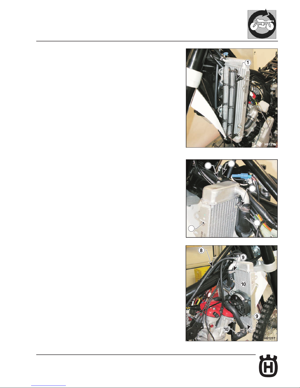
E.37Part. N. 8000 H2051 (02-2010)
H006014
6
3
4
2
7
GENERAL PROCEDURES
Radiator removal
- Remove the fuel tank together with scoops and spoilers as outlined in the
relevant paragraphs.
- Remove the electric cooling fan and its bracket as described in the relevant
paragraph.
- Drain all coolant as described in the relevant paragraph (see Section "D").
- Release the grids (1) and remove them.
- Loosen the clamps (2) and disconnect the hoses (3) from the left-hand radiator
(4).
- Open the clamp (6) and disconnect the hose (7).
- Disconnect the breather hose (8).
- Loosen the clamps (9) and disconnect the hoses (10) from the right-hand
radiator.
Page 96
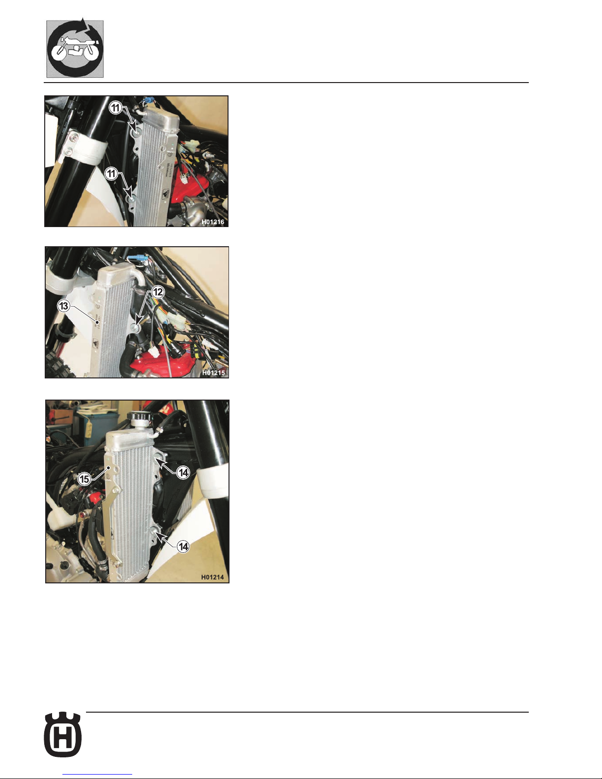
E.38 Part. N. 8000 H2051 (02-2010)
GENERAL PROCEDURES
- Use a 7 mm ring wrench to loosen the two screws (11) and a 5 mm Allen
wrench to loosen the central screw (12). Remove the left-hand radiator
(13).
- Loosen the two screws (14) using a 7 mm ring wrench and remove the righthand radiator (15).
Page 97
F.1Part. N. 8000 H2051 (02-2010)
F
ENGINE DISASSEMBLY
Section
Page 98
F.2 Part. N. 8000 H2051 (02-2010)
ENGINE DISASSEMBLY
Layout of engine components ...................................................................... F. 3
Cylinder head cover removal ........................................................................ F. 4
Camshaft removal ........................................................................................ F. 4
Water pump body removal ........................................................................... F. 8
Water pump disassembly ............................................................................. F. 8
Cylinder head removal.................................................................................. F.9
Valve removal ............................................................................................. F.12
Cylinder removal......................................................................................... F.14
Piston removal ........................................................................................... F.15
Flywheel removal ....................................................................................... F.15
Clutch cover removal .................................................................................. F.18
Oil lters removal ........................................................................................ F.19
Clutch disassembly..................................................................................... F.20
Clutch actuator removal.............................................................................. F.23
Starter motor ange removal ...................................................................... F.24
Starter motor removal ................................................................................. F.24
Gearbox drive shaft removal ...................................................................... F.25
Gear sensor removal .................................................................................. F.27
Crankcase, crankshaft and countershaft disassembly ............................... F.28
Left crankcase seal replacement ................................................................ F.31
Countershaft removal ................................................................................. F.32
Gearbox disassembly ................................................................................. F.32
Crankshaft removal .................................................................................... F.33
Crankshaft components removal ................................................................ F.34
Right crankcase crankshaft seal removal ................................................... F.35
Crankcase bearings removal ...................................................................... F.35
Oil pump disassembly ................................................................................ F.36
Stator removal ............................................................................................ F.36
Page 99
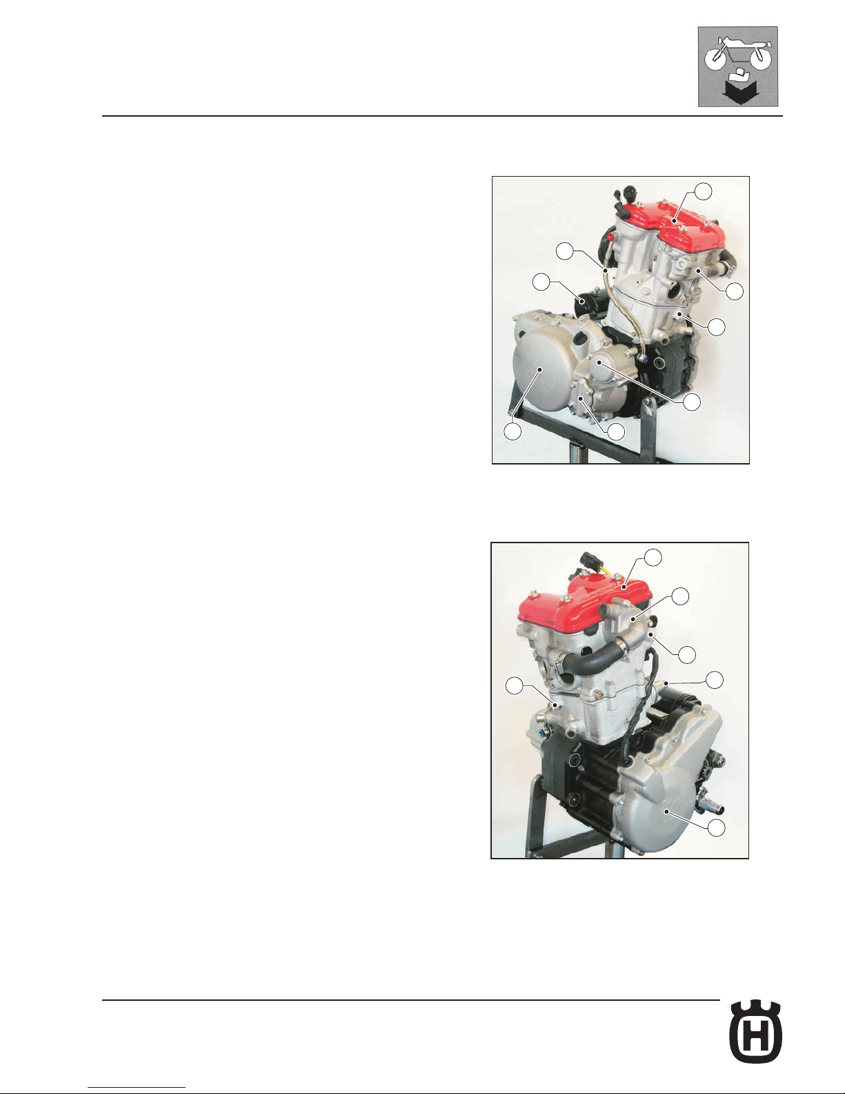
F.3Part. N. 8000 H2051 (02-2010)
1
4
9
2
7
5
11
H006022
6
1
2
8
4
H006023
10
3
ENGINE DISASSEMBLY
Layout of engine components
1 Cylinder head cover
2 Cylinder head
3 Chain tensioner
4 Cylinder
5 Starter motor
6 Head lubrication pipe
7 Oil pump
8 Clutch cover
9 Oil lter
10 Water pump
11 Ignition cover
Page 100
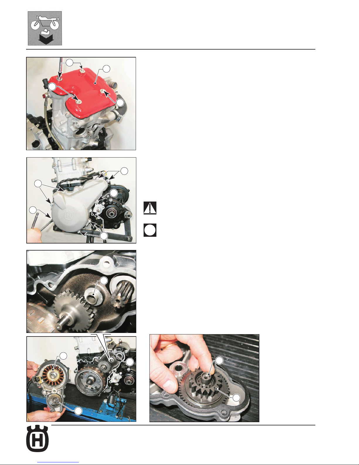
F.4 Part. N. 8000 H2051 (02-2010)
H006024
1
1
1
2
H006025
1b
1
1a
1
1
H006026
3
4
6
5
H006027
7
4
ENGINE DISASSEMBLY
Cylinder head cover removal
- Remove the four retaining screws (1) (8 mm wrench) and remove the head
cover (2) with its gasket.
Camshaft removal
- Remove the head cover as described in the relevant paragraph.
- Remove the eight screws (1) securing the ignition cover (2) (8 mm wrench)
and remove the cover together with stator (3), timing drive gears (4) and
gasket.
The two longer screws (1a and 1b) (L=65mm) must be retted in their
original positions.
Make sure to collect the starter drive bushing (5); remove it from the
ange (6) and t it on the shaft (7) of starter drive gear (4).
 Loading...