

Page 1

1
Workshop Manual
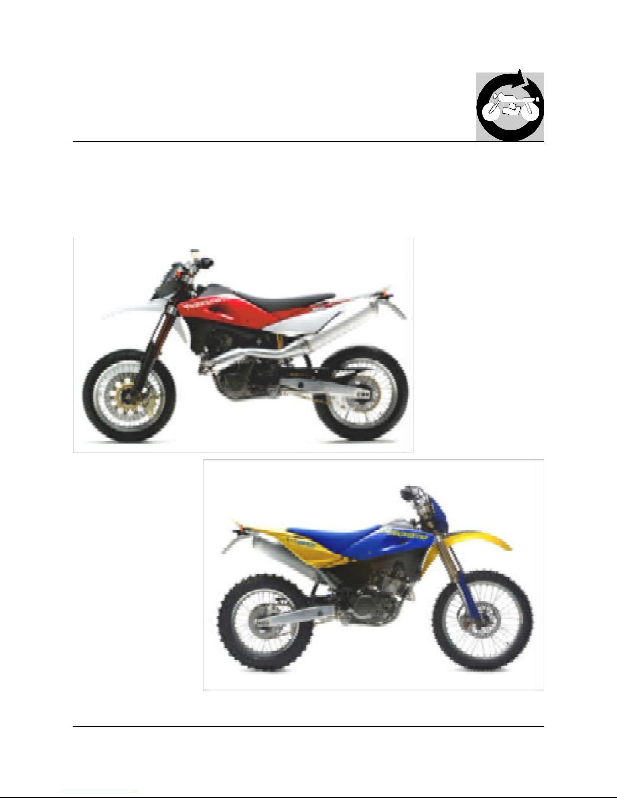
SM 610, TE 610/ 2006
Part. N. 8000 A4640 (04-2005)
http://husqy.forumsactifs.com
Page 2

2
Copyright by
MV Agusta M otorcycles S.p.A.
Servizio Assistenza Tecnica - Via Nino Bixio, 8
21024 Cassinetta di Biandronno (VA) - Italy
Tel. ++39 0332 254111- Fax ++39 0332 756509 www.husqvarna.it
USA m odel
Cagiva U.S.A.
2300 MARYLAND ROAD
WILLOW G RO VE, PA 19090 - 4193
215 - 830 - 3300
1st Edition (04-2005)
Printed in Italy
Print No. 8000 A4640
VALIDITY (from vehicle identification number)
SM 610 (39 KW ): ZC GA100AB5V000001
SM 610 (22 KW ): ZC GA101AB5V000001
TE 610 E (39 KW): ZCG A100AA5V000001
TE 610 E (22 KW): ZCG A101AA5V000001
USA/C DN m odels
SM 610: ZCGAFEK P#6V400000
TE 610: ZCG EAEKP#6V300000
To the best knowledge of M V Agusta Motorcycles S.p.A. - Varese, Inc. the material contained herein is accurate as of the date
this publication was approved for printing. Cagiva Motor S.p.a. - Varese, Inc. reserves the right to change specifications,
equipment, or designs at any time without notice and without incurring obligation. Illustrations in this manual are merely for
demonstration purposes and could not exactly match the detail described. No part of this manual can de reproduced without
permission in writing of the copyright holder. All the motorcycles and their detailed parts taking part in competitions of any
type are excluded from the guarantee.
1st Edition (04-2005)
http://husqy.forumsactifs.com
Page 3

3
Forew ord
This publication intended for HUSQVARN A Workshops has been prepared for the purpose of helping the authorized personnel in
the maintenance and repair work of the motorcycles herewith dealt with. The perfect knowledge of the technical data contained
herein is essential for a m ore complete professional training of the operator.
The paragraphs have been com pleted with schematic illustrations evidencing the subject concerned, in order to enable a more
immediate understanding.
This manual contains information with particular meanings:
Accident prevention rules for the operator and for the personnel working near by.
Possibility of damaging the vehicle and/or its components.
Additional information concerning the operation under way.
Useful suggestions
HUSQV AR NA suggests, in order to prevent troubles and in order to have an excellent final result, to generically com ply with the
following instructions:
in case of repair work, weigh the impressions of the Customer who complains about the im proper operation of the motorcycle,
and formulate proper clearing questions about the symptoms of the trouble.
detect clearly the cause of the trouble. This manual gives the theoretical bases which however shall be integrated by the per-
sonal experience and by the attendance to training courses periodically organized by HUS QV ARNA.
rationally plan the repair work in order to prevent dead time as for instance procurement of spare parts, tool preparation, etc.
reach the component to be repaired and perform only the required operations. In this connection, it will be useful to consult the
disassembly sequence contained in this manual.
1 Always replace the seal rings and split pins with new com ponents.
2 W hen loosening or tightening nuts or bolts, always start from the bigger ones or from the center. Lock at the prescribed torque
wrench setting following a crossed run.
3 Always earm ark the components or positions which could be m istaken one for another at the time of assembly.
4 Use original HU SQVARNA spare parts and the lubricants of the recomm ended brands.
5 Use special tools, where specified.
6 Consult the Service Bulletins as they may contain up-dated adjustment data and repair methodologies.
http://husqy.forumsactifs.com
Page 4

4
- Where not otherwise specified, data and instructions refer to all models.
SM 610
TE 610
http://husqy.forumsactifs.com
Page 5

5
Chapter
Section
General
A
Maintenance B
Troubles and remedies C
Settings and adjustments D
General operations E
Engine disassem bly F
Engine overhauling G
Engine re-assembly H
Front suspension I
Rear suspension J
Brakes L
Electric system M
Engine cooling system N
Lubrication circuit O
Specific tools W
Torque wrench settings X
Fram e, wheels Y
Notes for USA/CDN-AUS models Z
Summary
http://husqy.forumsactifs.com
Page 6

6
http://husqy.forumsactifs.com
Page 7

1
GENERAL
Section
http://husqy.forumsactifs.com
Page 8

2
Engine A.3
Timing system A.3
Fuel feeding A.3
Lubrication A.3
Cooling A.3
Ignition A.3
Starting A.3
Transmission A.4
Frame A.5
Suspensions A.5
Brakes A.5
Wheels A.5
Tires A.5
Ignition system- electric system A.6
Weights A.7
Overall dimensions A.7
Table of Contents
Capacities A.8
GENERAL
http://husqy.forumsactifs.com
Page 9

3
GENERAL
ENGINE
4-stroke, single cylinder
Bore 3.85 in.
Stroke 3.01 in.
Displacement 35.15 cu. in.
Compression ratio 11.1:1
TIM ING SYSTEM
Single overhead cam shaft; 4 valves
Valve angle in relation to cylinder:
INTAKE 20°
EXHAUST 20°
Valve clearance with cold engine:
INTAKE 0.002 in.
EXHAUST 0.002 in.
FUEL FEEDING
Gravity
Dry type air filter
Carburetor type Keihin FCR-M X 41 with acceleration
pump and T.P.S. (Throttle Position Sensor)
LUBRICATION
Forced type with lobe twin-pum p
COOLING
By fluid with double cooler, electric fan and expansion tank
IGNITION
Electronic with capacitive discharge; Digital controlled variable
spark advance
Spark plug type "NGK" CPR8E
Spark plug gap 0.022÷0.026 in.
STARTING electric
http://husqy.forumsactifs.com
Page 10

4
GENERAL
TRANSMISSION
Multi-plate clutch in oil bath 6-speed gearbox, constant
mesh gear type
Drive between engine and gearbox m ain shaft by straight
toothed gears
Prim ary drive
Drive pinion gear z 32
Clutch ring gear z 75
Transmission ratio 2.343
Gearbox ratios
1st gear 2.615 (z 34/13)
2nd gear 1.812 (z 29/16)
3rd gear 1.350 (z 27/20)
4th gear 1.091 (z 24/22)
5th gear 0.916 (z 22/24)
6th gear 0.769 (z 20/26)
Final drive
Drive between gearbox and rear wheel by 5/8" x 1/4" chain
(with O Rings )
* Transm ission sprocket z 15
Rear wheel sprocket z 45
* Transm ission ratio 3.000
Rear chain size 5/8 x1/4
(112 links)
* Total drive ratios
1st gear 18,389
2nd gear 12,744
3rd gear 9,492
4th gear 7,670
5th gear 6,445
6th gear 5,409
*: replace data on owner s manual no. 8000 A4860 (page 22)
http://husqy.forumsactifs.com
Page 11

5
GENERAL
* FR AM E
Single-beam in steel tubes of circular section splitting approx.
on line with the exhaust; light alloy rear fram e
Steering angle 39° each side
Steering axis angle 27° (SM ); 28° (TE)
Forward travel (in.) 2.7 (SM); 3.9 (TE)
*: replace data on owner s manual no. 8000 A4860 (page 24)
SUS PENSION
Front
MARZO CC HI Overturned forkrod telehydraulic fork with
advanced pin; forkrods 1.77 in. diam eter; hydraulic brake
adjustment both in compression and extension
Axle travel on leg axis (in.) 9.84 (SM); 11.8 (TE)
Rear
Swinging arm in light alloy with progressive damping,
SACHS hydraulic mono-shock absorber with helical spring.
Spring preloading adjustment; hydraulic brake adjustm ent
both in compression (D OUBLE) and in extension.
Wheel travel (in.) 11.4 (SM); 12.6 (TE)
BRAKE S
Front
Drilled fixed disc 10.24 in. dia. with floating caliper (TE);
drilled floating disc 12.6 in. dia. (SM) with fixed caliper
Pads area 5.02 sq. in. (TE); 6.14
sq. in. (SM)
Independent hydraulic circuit and pump with control on the
handlebar right side
Rear
Drilled floating disc ø 8.66 in. with
floating caliper
Pads area 4.57 sq. in.
Independent hydraulic circuit; controlled by pedal and pump
on the motorcycle right side.
WHEELS
Rims
Front (TE) "TAKASAG O Excel in
light alloy: 1,6x21
Front (SM) "SANREM O" in light
alloy: 3,50x17
Rear (TE) "Metzeler" MCE KA-
ROO- "Pirelli" MT 21;
140/80x18
* (SM) "Pirelli" MTR 22
DIABLO- "Dunlop"
D208; 150/60x17
*: replace data on owner s manual no. 8000 A4860 (page 26)
Cold tire pressure
(front SM - Road use, driver only)
25.6 psi
(front SM - Road use, driver and passenger)
28.4 psi
(rear SM- Road use, driver only)
28.4 psi
(rear SM- Road use, driver and passenger)
34.1 psi
(front SM - Racing use, driver only)
20 psi
(rear SM- Racing use, driver only)
22.7 psi
(front TE- Road use, driver only)
17.1 psi
(front TE- Road use, driver and passenger)
21.3 psi
(rear TE- R oad use, driver only)
21.3 psi
(rear TE- R oad use, driver and passenger)
25.6 psi
(front TE- Racing use, driver only)
14.2 - 15.6 psi
(rear TE- R acing use, driver only)
12.8 - 14.2 psi
http://husqy.forumsactifs.com
Page 12

6
IGNITION SYSTEM - ELECTRIC SYSTEM
The ignition system includes the follow ing elements:
- Generator;
- Ignition coil;
- Electronic power unit;
- Voltage regulator;
- Spark plug;
- Starting motor 12V-700W ;
- Electric start remote control switch.
The electric system includes the following elements:
- SM- Headlamp with two filaments bulb of 12V-55/60W and parking light bulb of 12V-5W ;
- TE- Headlam p with two filaments bulb of 12V-35/35W and parking light bulb of 12V-3W;
- Rear lights with stop bulbs of 12V-21W and parking light bulb of 12V-5W ;
- Turn signals bulb of 12V-10W ;
- Three15 A fuses (one of them is a spare fuse);
- Battery 12V-12Ah.
GENERAL
http://husqy.forumsactifs.com
Page 13

7
WEIG HTS (§)/ D IM ENSIONS mm
GENERAL
SM 610
TE 610
(§): Curb w eight, without fuel
SM 610 .....................kg 142 (313 lbs)
TE 610 ..................... kg 140 (308.6 lbs)
http://husqy.forumsactifs.com
Page 14

8
CAPACITIES
Fuel tank (reserve included) Unleaded gasoline (98 R.O.N.) 2.64 Imp. Gall./ 3.17 U.S. G all.
Fuel reserve
2.64 Imp. Qt./ 3.17 U.S. Qt.
Change gear and main transmission oil AGIP RACING 4T (SAE 10W60) 1.76 Imp. Qt./ 2.11 U.S. Qt.
( oil and oil filter replacement)
1.14 Imp. Qt./ 1.37 U.S. Qt.
( oil replacem ent)
Front fork oil AGIP FORK 7,5 (SAE 7,5; SAE 5 for hard
climatic conditions)
4 in. (oil level) (*)
Oil for rear shock - absorber AGIP FORK 2,5 (SAE 2,5)
Fluid for cooling system AGIP COOL 2.45 Imp. Pints; 2.85 U.S. Pints
Front brake fluid AGIP BRAKE 4 (DO T 4)
Rear brake fluid AGIP BRAKE 4 (DO T 4)
Drive chain lubrication AGIP CHAIN LUBE
Grease lubrication AGIP BIKE GREASE
Electric contact protection AGIP ROCOL MOISTURE GUARD
Fillers for radiator AREXONS liquido
Air filter oil AGIP FORM ULA FILTER "Foam air filter
protection oil"
Air filter detergent AGIP "Filter clean foam air detergent fluid"
GENERAL
WARNING! - Use of additives in fuel or lubricants is not allowed
(*): see page I.9
http://husqy.forumsactifs.com
Page 15

1
Section
MAINTENANCE
http://husqy.forumsactifs.com
Page 16

2
Description Operation Pre-delivery
Engine oil
Coolant Check / Restore level #
Cooling system Check for leakage #
Spark plugs Check / Replace #
Throttle body / C arburetor Check and adjust #
Brakes / Clutch fluid Check level #
Brakes / Clutch Check operation #
Brakes / Clutch Check lines for leakage #
Throttle control Check operation #
Throttle control Check / Adjust play #
Choke control Check operation #
Flexible controls and transmissions Check / Adjust #
Drive chain Check / Adjust #
Tires Check pressure #
Side stand Check operation #
Electrical equipment Check operation #
Instrument panel Check operation #
Lights / Visual signals Check operation #
Horn Check operation #
Headlight Check operation #
Ignition switch Check operation #
Locks Check operation #
Screws and nuts Check / Tighten #
Hose clamps Check / Tighten #
General lubrication
General test
PRE -DELIVERY INSPECTION
MAINTENANCE
http://husqy.forumsactifs.com
Page 17

3
MAINTENANCE
PERIODIC MAINTENANCE SCHEDULE
CO UP O N A AF T ER
1000 km (6 20
mi.) O R
6 MONTHS
CO UP O N B AF T ER
5000 km (3 100
mi.)
OR 12 MONTHS
CO UP O N C AF T ER
10000 k m (6200
mi.)
OR 24 MONTHS
CO UP O N D AF T ER
15000 k m (9300
mi.)
PR E -DEL IVE R Y
INSPEC T ION
Whichever
com es first
Whichever com es
first
Whichever
com es first
Only if reac hed
within 24 m onths
Coolant C C C S C
Engine oil C S S S S
Engine oil filter cartridge
S
S
Engine oil suction filter
P
P
Valve clearance
C C C C
Spark plug C C
S
Tim ing system chain
S
Clutch flexible coupling
C
Ignition cover
C C C
Starting gears assembly
C
Connecting rod
S
Clutch discs
C
Ignition timing
C
Fuel filter
C S S S
Carburetor C C
P
Carburetor throttle valve
C
Air filter
P S S S
Engine oil pressure
C
Cylinder/Piston checking
C
C
Brakes fluid (**) C C C S C
Brakes hydraulic controls C C C C C
Brakes pads wear
C
C
Flexible controls C C L L L
Throttle control C C C C C
Tires pressure and wear (*) C C C C C
Electric fan C C
C
Headlamp alignment C C
Lights/Visual signals, Horn C C C C C
Battery C C C C C
ITEM
CO UP O N E AF T ER
20000 k m
(124 00 m i.)
Only if reac hed
within 24 m onths
S
S
S
P
C
S
S
C
C
C
S
C
S
P
C
S
C
C
S
C
C
L
C
C
C
C
C
SE E P AGE
Instruments C
http://husqy.forumsactifs.com
Page 18

4
MAINTENANCE
PERIODIC MAINTENANCE SCHEDULE
ITEM
CO UP O N A -
AF T ER
1000 km (6 20
mi.) O R
6 MONTHS
CO UP O N B -
AF T ER
5000 km (3 100
mi.)
OR 12 MONTHS
CO UP O N C -
AF T ER
10000 k m (6200
mi.)
OR 24 MONTHS
CO UP O N D -
AF T ER
15000 k m (9300
mi.)
CO UP O N E -
AF T ER
20000 k m
(124 00 m i.)
SE E P AGE
PR E -DEL IVE R Y
INSPEC T ION
Whichever
com es first
Whichever com es
first
Whichever
com es first
Only if reac hed
within 24 m onths
Only if reac hed
within 24 m onths
Rims spokes stretch
C C C C C
Steering head bearings play
C
C
C
Transmission chain/Chain rollers C C-L C-L S C-L S
Rear sprocket/Pinion
C S C S
Side stand screws C C C C C C
Wheels hubs bearings
C
C
Fuel tank
P
P
Front fork oil
S-R
S-R
Bolts and nuts general tightening C C C C C C
Lubricating/G reasing C L L L L L
Locks C
Motorcycle general test X X X X X X
KEY FOR M AINTENANCE SC HE DULE
C: Check and/or adjust
L: Lubricate and/or grease
P: Clean
S: Replace
R: overhauling
(*): replace if necessary
(**): system bleeding if necessary
http://husqy.forumsactifs.com
Page 19

1
TROUBLESHOOTING
Section
http://husqy.forumsactifs.com
Page 20

2
TROUBLESHOOTING
ENG INE
Trouble Cause Rem ed y
Engine don
t start or starts with
difficulty
Inadequate com pression 1. Piston seizure Replace
2. Con-rod small or big end seized Replace
3. Piston rings worn Replace
4. Cylinder worn Replace
5. Low torque cylinder head nuts Tighten
6. Head gasket blowing Replace
7. Spark plug loose Tighten
8. Incorrect valve play Adjust
9. Valve springs weak or seized Replace
10. Valves seized Replace
11. Incorrect decom pressor adjustment Adjust
No or w eak spark 1. Spark plug faulty Replace
2. Spark plug dirty or wet Clean or dry
3. Spark plug gap too large Adjust
4. Ignition coil faulty Replace
5. H.T. leads dam aged or short circuiting Check
6. Electronic device faulty Replace
7. R.H. switch faulty Replace
Fuel not reaching carburetor 1. Fuel tank cap breather blocked Clean
2. Fuel cock blocked Clean
3. Fuel feed hose blocked Clean
4. Carburetor fuel filter dirty Clean
5. Worn out float valve or worn out floats Replace
6. Rocker blocking float valve Free
Carburetor flooding 1. High fuel level in float bowls Adjust
2. Worn out float valve or worn out floats in open position Replace or free
Worn out clutch sw itch on the
handlebar
Clutch switch cable connected incorrectly or short circuit Connect correctly or replace
http://husqy.forumsactifs.com
Page 21

3
TROUBLESHOOTING
Trouble Cause Rem ed y
Engine cuts out easily 1. Spark plug dirty Clean
2. Electronic control unit faulty Replace
3. Carburetor jets blocked Clean
4. Idling low Adjust
Engine noisy
Piston noise 1. Excessive play between cylinder liner and piston Replace
2. Piston rings or piston rings seats worn Replace
3. Excessive carbon layers inside the combustion chamber or on the piston top
Clean
4. Worn rocker arm Replace
5. Excessive valve play Adjust
6. Valve springs weak or seized Replace
7. Cam chain worn Replace
Crankshaft noise 1. Main bearings worn Replace
2. High radial and axial play at con-rod big end Replace
3. Crankshaft gear damaged Replace
4. Crankshaft nut loose Tighten
Clutch noise 1. Discs worn Replace
2. Excessive free play between clutch drum and driving
discs
Replace
Gearbox noise 1. Gears worn Replace
2. Gear splines worn Replace
Rear transmission chain noise 1. Chain stretched or badly adjusted Replace or adjust
2. Engine sprocket and rear wheel sprocket worn Replace
Clutch slip 1. Insufficient clutch adjuster free play Adjust
2. Clutch springs weak Replace
3. Clutch discs worn Replace
http://husqy.forumsactifs.com
Page 22

4
TROUBLESHOOTING
Trouble Cause Rem ed y
Clutch drag 1. Excessive clutch adjuster free play Adjust
2. Spring tension uneven Replace
3. Clutch discs bent Replace
Gears not engaging 1. Gearshift forks bent or seized Replace
2. Gear change pawls worn Replace
3. Gearshift forks
control pins damaged Replace
Gear change lever doesn
t return 1. Selector return spring weak or broken Replace
2. Gearshift forks worn Replace
Slips out of gear 1. Sliding dogs worn Replace
2. Gear splines worn Replace
3. Sliding dog seats on gears worn Replace
4. Splines gearshift forks
control shaft worn Replace
5. Gearshift forks control pins worn Replace
Engine lacks pow er 1. Air filter dirty Clean
2. Carburetor m ain jet blocked or wrong size Clean or replace
3. Poor quality fuel Replace
4. Intake manifold loose Tighten
5. Spark plug gap too large Adjust
6. Inadequate compression Find cause
7. Incorrect valve play Adjust
8. Faulty valve guides or seats Replace
9. Valve springs weak or seized Replace
Engine overheating 1. Excessive coke on combustion chamber and/or piston
crown
Clean
2. Insufficient engine oil, or wrong oil used Top up or replace
3. Radiator air flow blocked Clean
4. Poor seal at cylinder head gasket Replace
5. Clutch slipping Adjust
6. Faulty electric fan Replace thermo switch
http://husqy.forumsactifs.com
Page 23

5
TROUBLESHOOTING
FRAME W HEELS AND SUSPENSION
Trouble Cause Rem ed y
Difficult to turn handlebars 1. Low tire pressure Inflate
2. Steering head bearings
adjustment ring nut or steering
stem nut too tight
Adjust
3. Bent steering head stem Replace steering bracket
4. Steering head bearings worn or seized Replace
Handlebar vibrates 1. Front fork legs bent Replace
2. Front wheel axle bent Replace
3. Frame bent Replace
4. Front wheel rim bent Replace
5. Front wheel bearings worn Replace
Suspension too hard 1. Insufficient oil in front fork stanchions Top up
2. Too low viscosity of front fork stanchion oil Replace
3. Weak front fork spring Replace
4. Weak rear shock absorber spring Replace
5. Rear shock absorber badly adjusted Adjust
Wheel (front and rear)
vibrates
1. Wheel rim bent R eplace
2. Wheel hub bearings worn Replace
3. Wheel spokes loose Tighten
4. Wheel axle nut loose Tighten
5. Rear swinging arm bearings worn Replace
6. Chain tensioner incorrectly set Adjust
7. Wheel not balanced correctly Balance
Rear suspension noisy 1. Link rod bearings or spacers worn Replace
2. Shock absorber ball joints worn Replace
3. Shock absorber faulty Replace
http://husqy.forumsactifs.com
Page 24

6
TROUBLESHOOTING
Trouble Cause Rem ed y
Poor (front and rear) braking 1. Air in the brake system Bleed
2. Insufficient fluid in reservoir Top up
3. Pads and/or disc worn Replace
4. Disc damaged R eplace
5. Brake lever- pedal incorrectly adjusted Adjust
6. Water inside the braking system Replace the fluid
ELECTR ON IC S
Spark plug becomes dirty too
frequently
1. Mixture too rich Adjust carburetor
2. Air filter dirty Clean
3. Piston rings worn Replace
4. Piston or cylinder worn Replace
Spark plug overheats 1. Mixture too lean Adjust carburetor
2. Spark plug gap too small Adjust
3. Too high heat rating Replace the spark plug
Generator charging too low or
not at all
1. Wires to voltage regulator connected incorrectly or short
circuiting
Connect correctly or replace
2. Faulty voltage regulator Replace
3. Generator coil faulty Replace
Generator charging too high 1. Voltage regulator faulty Replace
The battery is discharged fast 1. Battery terminals dirty Clean
Start motor w on't start or slips 1. Battery flat Recharge
2. Control button on right hand switch unit faulty Replace
3. Starter relay faulty Replace
4. Starter motor faulty Repair or replace
5. Starter gears worn Replace
6. Free wheel rollers worn or damaged Replace free wheel
http://husqy.forumsactifs.com
Page 25

1
SETTINGS AND ADJUSTMENTS
Section
http://husqy.forumsactifs.com
Page 26

2
SETTINGS AND ADJUSTMENTS
Table of Contents
Adjustm ent of valves play
D.3
Compression check D.3
Carburetor adjustm ent D.4
Idle adjustment D.4
Checking the engine oil level D.4
Oil change, cleaning and changing oil filters D.5
Cleaning the bag filters D.6
Coolant level check D.6
Replacem ent of coolant D.7
Air filter check and cleaning D .8
Throttle cable adjustm ent D.9
Clutch adjustm ent D.10
Adjustment of front brake control lever and
fluid level
D.11
Adjustment of rear control pedal D.12
Steering bearings play adjustm ent D.13
Front fork adjustment and oil level checking D.14
Adjusting the shock absorber D.15
Secondary transmission chain adjustm ent D.16
http://husqy.forumsactifs.com
Page 27

3
SETTINGS AND ADJUSTMENTS
Adjustm ent of valves play
Remove seat, spoilers, fuel tank, coolers and expansion tank as shown at
chapter
General Operations .
Drain the engine oil as indicated on page D. 5 then, with COLD ENGINE,
operate as follows:
- Rem ove the spark plug and insert a dial gauge into its seating;
- Rem ove the L.H. crankcase half cover (A) and position the tool (B) code
800090875 as shown in the figure;
- Bring the piston to the top dead center (TDC), with the
T notch on the rotor
coincident with the notch on the tool; set the dial gauge to zero on this
position;
- Rem ove the adjusting screw caps and checks the valve play using a
gauge. The play must be 0.002 in. both for the intake and the exhaust;
- lf the above play is not met, loosen the counter-nuts (1) and act as required
other screws (2) until the required play is obtained;
- Torque again the counter-nuts (1) and install all parts previously rem oved.
Spark plug 8.8 ft-lb
L.H. cover fastening screw 5.8 ft-lb
Nut for valve adjusting screw 5.8 ft-lb
Valve cover fastening screw 5.8 ft-lb
TIG HTENING TORQUES
Com pression check
Compression should be checked as follows:
- Rem ove the spark plug and fit a pressure gauge in its place;
- Turn completely the throttle twist-grip;
- Turn the engine over by using the electric starter switch and take a reading
on the pressure gauges. The pressure reading should not be lower than: 8
bar (113 PSI).
http://husqy.forumsactifs.com
Page 28

4
SETTINGS AND ADJUSTMENTS
Carburetor adjustment
Adjust the carburetor with warm engine and with the throttle control in closed
position.
Proceed as follows:
- Turn slow running adjusting screw (1) on the left side of the bike, until the
engine is turning over at fairly high rpm (turn the screw clockwise to increase
the engine r.p.m. , and counterclockwise to decrease the engine r.p.m .).
- Turn adjusting screw (2) clockwise until the fully closed position is reached
then turn back 1,5 turns.
- Progressively loosen adjusting screw (1) to obtain the slow running required.
Idle adjustment
Adjust the carburetor with warm engine and with the throttle control in closed
position.
Proceed as follows:
- Turn slow running adjusting screw (1) on the left side of the bike, near the
fuel cock, until the required idle condition is reached (turn the screw
clockwise to increase the engine r.p.m ., and counterclockwise to decrease
the engine r.p.m.).
Checking the engine oil level
Put off the engine and wait for some minutes to allow the oil setting inside the
sump. With the motorcycle set in vertical position, and looking through window
(C), check that the level is between the two notches (A) and (B) placed at the
back of the rear brake pedal, as shown in figure.
http://husqy.forumsactifs.com
Page 29

5
SETTINGS AND ADJUSTMENTS
Be careful not to touch hot engine oil.
Oil change , cleaning and changing oil filters
Drain the oil w ith warm engine.
Work as follows:
- Set the motorcycle in vertical position and place a vessel under the engine;
- Rem ove oil filler cap (1) and drain plugs (2) and (3) under the sump to
drain all the oil;
- First rem ove possible particles from the magnetized care of the right plug,
then set the drain plugs and the gasket in position again (M14 plug: 24 Nm/
2,45 Kgm/ 18.1 ft-lb; M22 plug: 60 Nm/ 6,1 Kgm/ 44 ft-lb).
Add the required amount of oil through the oil filler (see page A.8).
Slowly turn the engine for some m inutes, the turn it off and wait for some
minutes to allow the oil setting inside the sump. With the motorcycle set in
vertical position, and looking through window (C), check that the level is
between the two notches (A) and (B) placed at the back of the rear brake
pedal, as shown in figure. To change the filter cartridge (5), unscrew the two
retaining screws (6), remove the cover (7) and the
O ring . Remove both
spring (8) and cartridge; replace the O-ring and reverse the operations when
reassembling (screw 6: 9,3 Nm / 0,95 Kgm / 6.9 ft-lb).
http://husqy.forumsactifs.com
Page 30

6
SETTINGS AND ADJUSTMENTS
Cleaning the bag filters
The filters (1) et (2) are set on the right side between the cover and the sum p
(transmission to the scavenge pump), and on the left sump (twin-filter,
transmission to the pressure pum p).
Clean the filters using gasoline and compressed air. Replace the old OR
gaskets with new and greased ones.
Pay attention to the filter (1) reassem bling sense.
Coolant level check
Check the level (2) in the right radiator with cold engine and with motorcycle in
vertical position. The cooler must be flush with the lower side of the filling pipe
union. The level inside the expansion tank must never be under the MIN (1).
Otherwise, ALWAYS and ONLY fill through the plug under the right radiator, or from
the expansion cap in case of level restoration.
Avoid removing the cap of the radiator w hen the engine is hot. There is a
risk that the coolant will spout and cause burns.
The coolant may not come on painted surfaces. lf this is the case w ash
with w ater.
http://husqy.forumsactifs.com
Page 31
7
SETTINGS AND ADJUSTMENTS
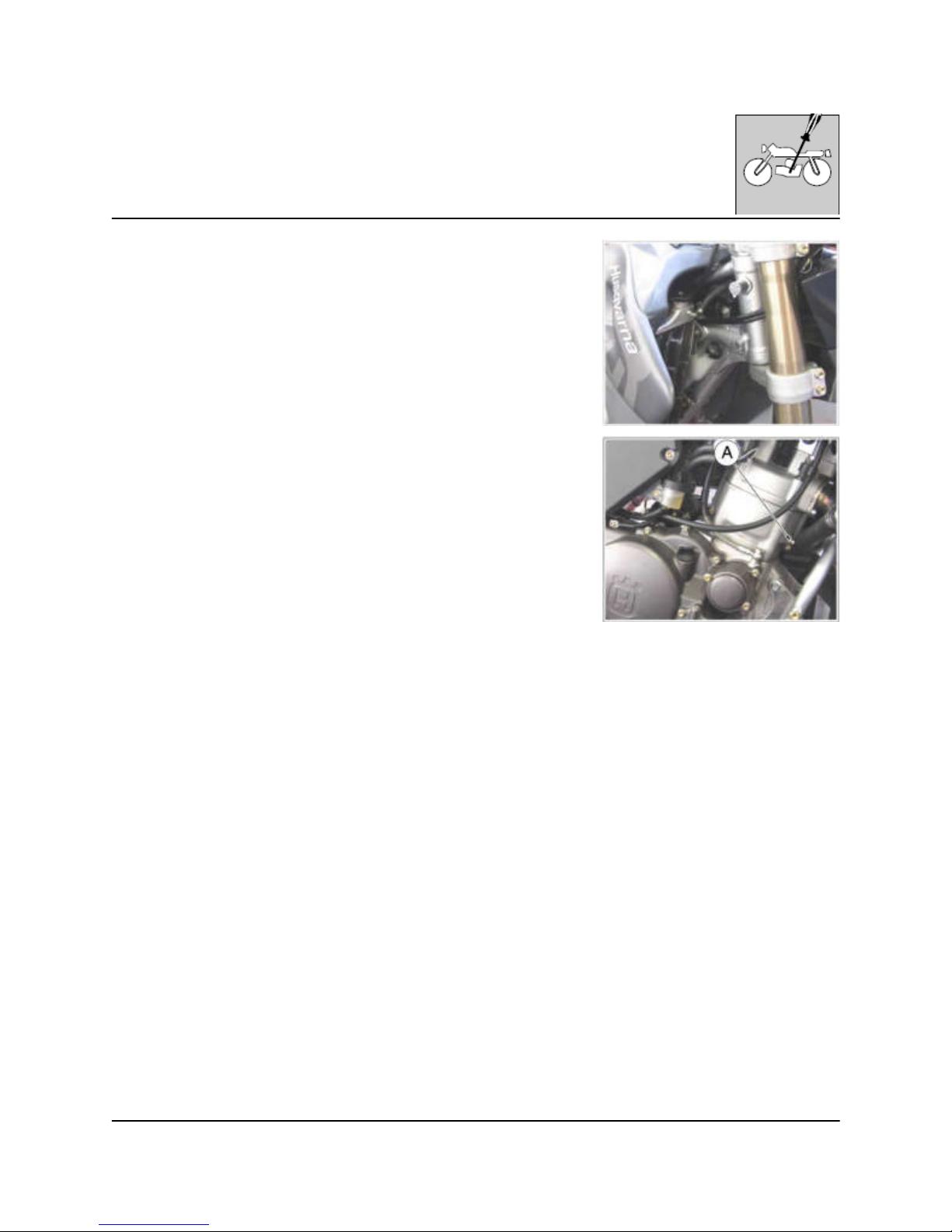
Replacement of coolant
Set a vessel under the engine and work as follows:
- remove the right radiator cap and the cooling fluid drain screw (A) set on the
right of the cylinder. W hen the fluid is fully drained, reassemble the drain screw
(check the gasket- tightening torque: 9,3 Nm/ 0,95 Kgm/ 6.9 ft-lb) and fill the
right reservoir with the required quantity (see page A.8). Slowly run the engine
to eliminate possible air bubbles, then check the levels again, following the
instructions on page D.6.
http://husqy.forumsactifs.com
Page 32
8
SETTINGS AND ADJUSTMENTS
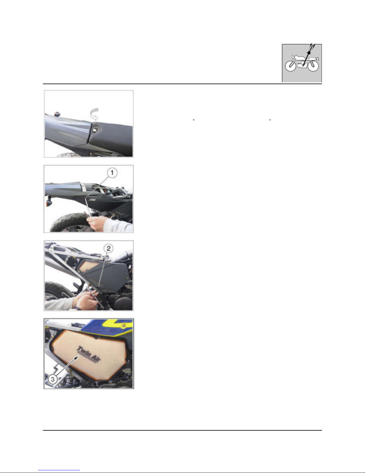
Air filter check and cleaning
Remove the saddle.
Remove the R.H. side panel rear fastening screw (1). Unhook the side panel
from the front side of the air filter box. Rem ove the air filter cover fastening
screws (2) (4 pcs.), the cover then the air filter (3). W ash the filter with a
specific detergent (AGIP
Filter clean foam air detergent fluid or sim ilar) then
dry it fully. Plunge the filter in special oil for filters (AGIP "Foam air filter
protection oil" or similar), then wring it to drain superfluous oil. Do not use
gasoline or a low flash-point solvent to clean the element. A fire or explosion
could result. Clean the element in a well ventilated area, and do not allow
sparks or flames anywhere near the working area. Reverse the operations
when reassem bling (tightening torque: air filter cover screw and R.H. side
panel: 6,5 Nm/ 0,65 Kgm/ 4.3 ft-lb).
http://husqy.forumsactifs.com
Page 33
9
SETTINGS AND ADJUSTMENTS
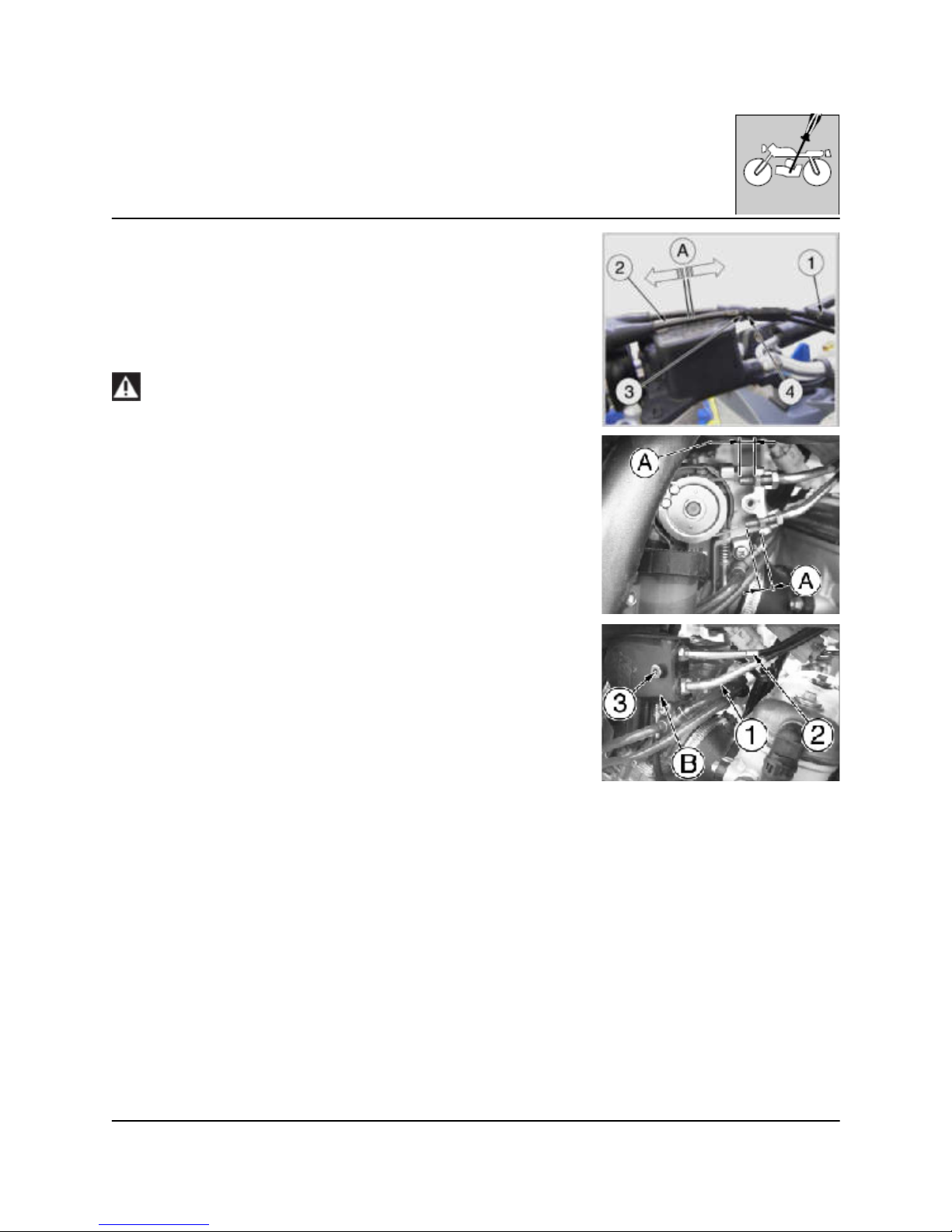
Throttle cable adjustm ent
To check the correct adjustment of the throttle operate as follows:
- remove the upper rubber cap (1);
- by moving cable (2) back and forth check for 2 mm (0.08 in.) clearance (A);
- should the clearance be incorrect, unblock the counter ring-nut (3) and turn
the adjusting screw (4) (by unscrewing it, the clearance is reduced, while by
screwing screw (4) it is increased);
- tighten the counter ring-nut again (3).
Operation w ith damaged throttle cable could result in an unsafe
riding condition.
In case of throttle control cables (1) and (2) replacement it is necessary to
respect, during reassembly, the measure A (10mm /0.4 in.), as shown in the
picture. Then reassemble guard cover (B) using screw (3) and adjust throttle
control cables on handlebar. To replace throttle control cables, first rem ove the
fuel tank as shown on page E.6.
http://husqy.forumsactifs.com
Page 34
10
SETTINGS AND ADJUSTMENTS
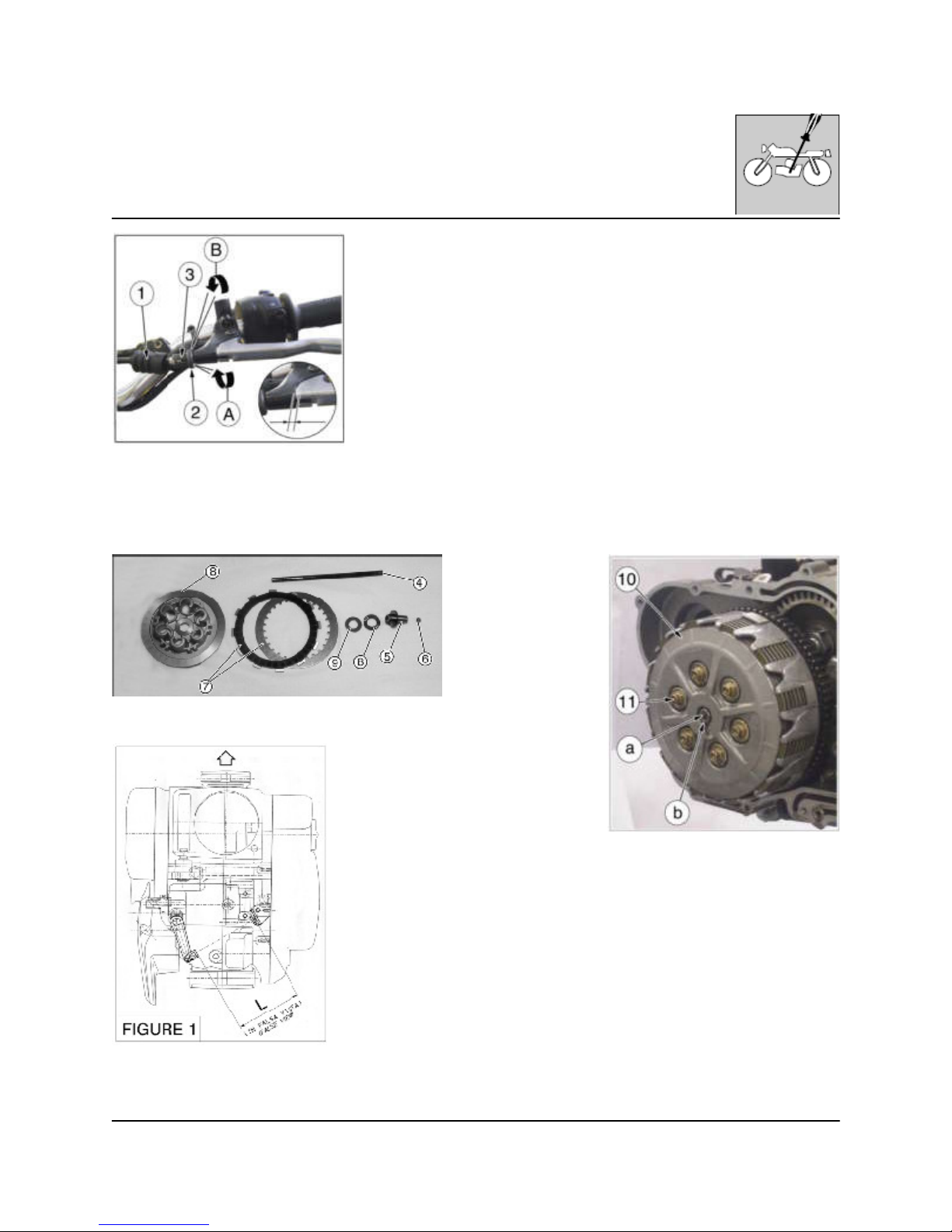
Clutch adjustment
The control Iever must have a 0.12 ÷ 0.20 in. idle stroke before beginning to disengage
the clutch. To adjust this slack, rem ove the rubber cap (1), Loosen the lock nut (2) and
operate the adjuster (3). The slack decreases when unscrewing, and increases when
screwing. Take care to tighten properly the Iock nut. If difficulties arise in reaching the
optimum value, turn adjuster Iocated on the crankcase.
In case the clutch disk were replaced, clutch shall be adjusted as follows:
- Set the clutch rod (4) in the slot of the primary shaft then, set the thrust cup (5) with
the balI engaged (6);
- Set the clutch Iever keeping a distance L=4.35 ÷ 4.43 in., on the crankcase (FIGURE
1).
Install the friction disk (7). Put first a Iined disk, then alternatively a non lined disk with a
Iined disk. Total quantity is eight Iined disks with seven non-Iined disks;
- Install the bearing (8), the washer (9), disk thrust plate (10) with six springs and relative bolts (11). Tighten to a torque value of 7,3 ft-Ib.;
- Align the index mark between the disk thrust plate and the thrust cup. Using a flat
screwdriver on the screw (a), tighten the jam nut (b);
- Reinstall the clutch cover (tightening torque: 9,3 Nm/ 0,95 Kgm/ 6.9 ft-lb), fill with the
necessary quantity of oil (see page A.8) and check the oil level;
- Adjust the clearance of the control Iever placed on the handlebar.
A: To decrease clearance
B: To increase clearance
L=110,5÷112,5 mm
(4.35 ÷ 4.43 in.)
http://husqy.forumsactifs.com
Page 35
11
SETTINGS AND ADJUSTMENTS
Adjustm ent of front brake control lever and fluid level check
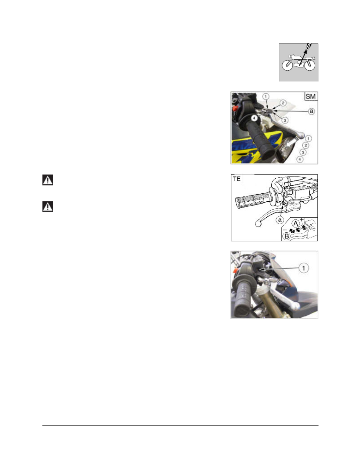
On the SM 610 model the lever position can be adjusted (4 adjustments)
for any driver hand size. To decrease the lever distance from the handle
grip, turn the adjuster (a) CLOC KW ISE. To increase the lever distance from
the handle grip, turn the adjuster (1) COUNTERCLOCKWISE.
On the TE 610 m odel the adjuster (a), located on the control lever, allows
adjusting of the position from which braking starts. Turn the adjuster (a)
CLOCKWISE in order to position the master cylinder in such a way that
braking occurs immediately upon lever action. Turn the adjuster (a)
COUNTERCLO CKWISE in order to position the master cylinder in such a
way that braking occurs slightly afterwards upon lever action.
The front fluid must not be lower than the minimum level (1) see from the
pump inspection window.
If the brake lever feels mushy when it is applied, there m ay be air in
the brake lines or the brake m ay be defective: CHECK TH E BRAKING
SYSTEM (page L.6).
If the lever free play is excessive, the brake action can decrease:
CHECK THE PADS THICKNESS (page L.5).
http://husqy.forumsactifs.com
Page 36
12
SETTINGS AND ADJUSTMENTS
Adjustm ent of rear control pedal
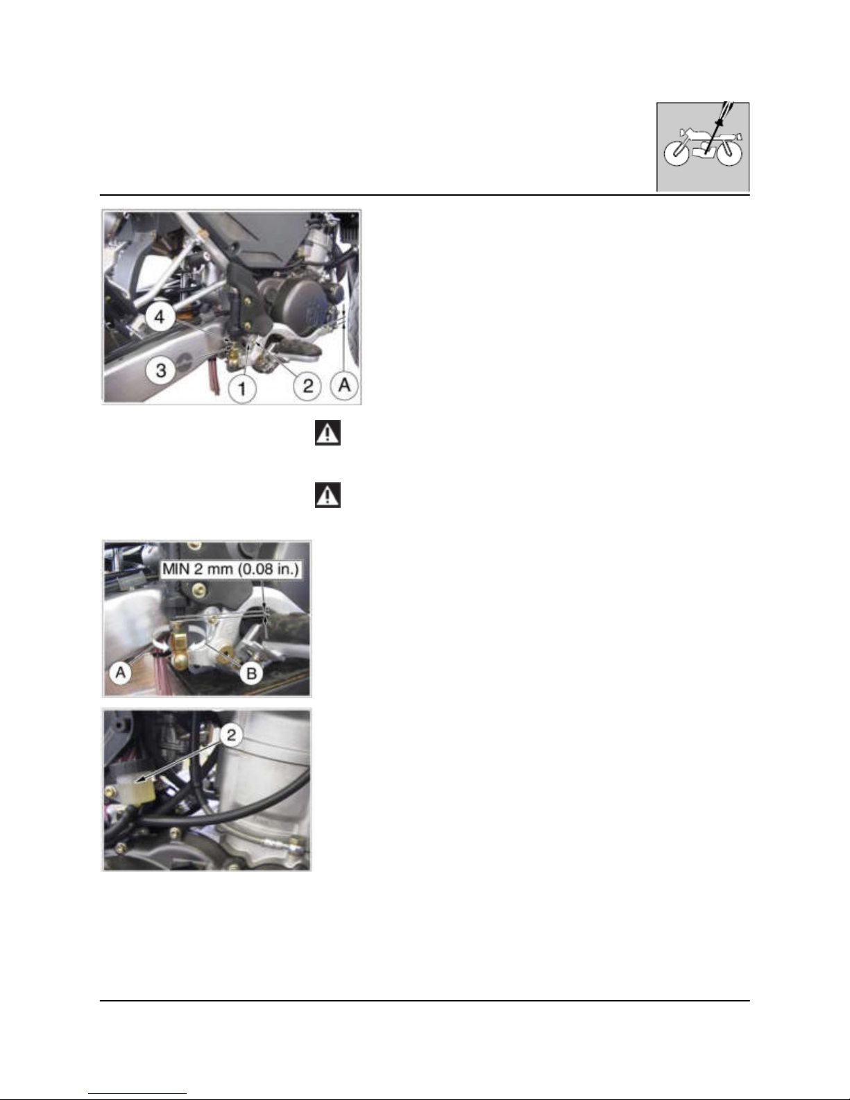
The position of the rear brake pedal as regards the footrest can be adjusted according to the personal requirem ents.
To carry out the adjustm ent, work as follows:
- loosen screw (2);
- adjust cam (1);
- tighten screw (2);
- check that play (A) of the pedal is approx. 5 mm (0.2 in.) before starting
the braking action;
- otherwise, loosen lock nut (3) and work on control rod (4) until the right
play is reached;
- tighten lock nut (3).
Never lower the play under 0.08 in. on the brake pump. The fluid
level must be between MIN and M AX of pump tank.
If the brake lever feels mushy when it is applied, there m ay be air in
the brake lines or the brake m ay be defective: CHECK TH E BRAKING
SYSTEM (page L.7).
If the lever free play is excessive, the brake action can decrease:
CHECK THE PADS THICKNESS (page L.5).
A: To decrease clearance
B: To increase clearance
TIG HTENING TORQUES
2: 14,7 Nm / 1,95 Kgm / 14.1 ft-lb
http://husqy.forumsactifs.com
Page 37
13
SETTINGS AND ADJUSTMENTS
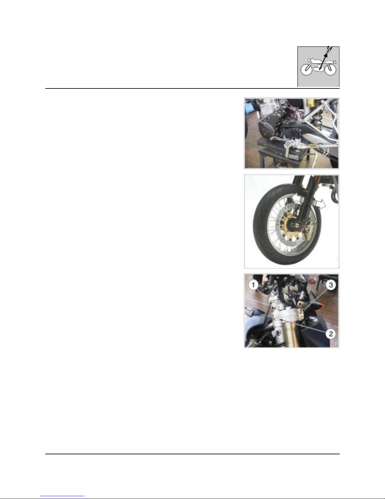
Steering bearings play adjustm ent
To ensure m aximum safety, the steering should always be adjusted so that
the handlebars rotate freely without play. To check steering adjustment,
place kick stand or other support under the engine so that the front wheel is
raised from ground. Place slight pressure on the tips of the handlebars to
rotate steering; the handlebars should also rotate without effort. Stand in
front of the motorcycle and grasp the lower end of the fork legs moving them
in the perpendicular direction to their axis.
If play is noticed, proceed with adjustment as follows:
- loosen steering sleeve nut (1);
- loosen four screws that fix steering head to fork legs (3);
- turn the steering ring nut (2) clockwise of the steering sleeve using a
proper tool, to adjust play properly;
- tighten steering sleeve nut (1) to a torque setting of 57,9÷65,1 Lb/ft;
(78,4÷88,3 Nm)
- tighten four screws on the steering head (3) to a torque of 22,5÷26,5 Nm
(16.6÷19.5 Lb/ft).
http://husqy.forumsactifs.com
Page 38
14
SETTINGS AND ADJUSTMENTS
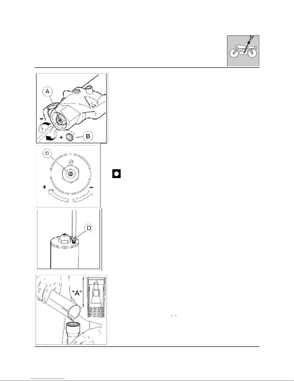
Adjusting the fork
a) COMPRESSION (LOW ER REGISTER)
Standard calibration: -12 clicks.
Remove plug (B) and turn register (A) clockwise until the position of fully
closed is reached then, turn back by the mentioned clicks. To obtain a
smoother braking action, turn the register anticlockwise. Reverse the
operation in order to obtain a harder action.
b) EXTENSION (UPPER REG ISTER)
Standard calibration: - 12 clicks.
To reset standard calibration turn register (C) clockwise to reach the position
of fully closed; then, turn back by the mentioned clicks. To obtain a smoother
braking action, turn the register anticlockwise. Reverse the operation in order
to obtain a harder action.
c) AIR VENT (to carry out after each competition, or monthly). Set the
motorcycle on a central stand and release the fork fully and loosen the air vent
valve (D). Once this operation is over, tighten the valve.
Never force the adjusting screws beyond the m axim um opening and
closure positions.
Oil fork level
For the regular fork operation, both legs must be provided with
the necessary oil quantity.
Remove the fork rods form the fork to check the oil level inside
the fork rods. W ork as follows:
- remove the power rod caps;
- remove springs from the stems letting the oil drop into the
latter;
- bring forks to stroke end;
- check that the level is at distance
A below the upper lim it of
rods
A = 100 m m (4 in.)
http://husqy.forumsactifs.com
Page 39
15
SETTINGS AND ADJUSTMENTS
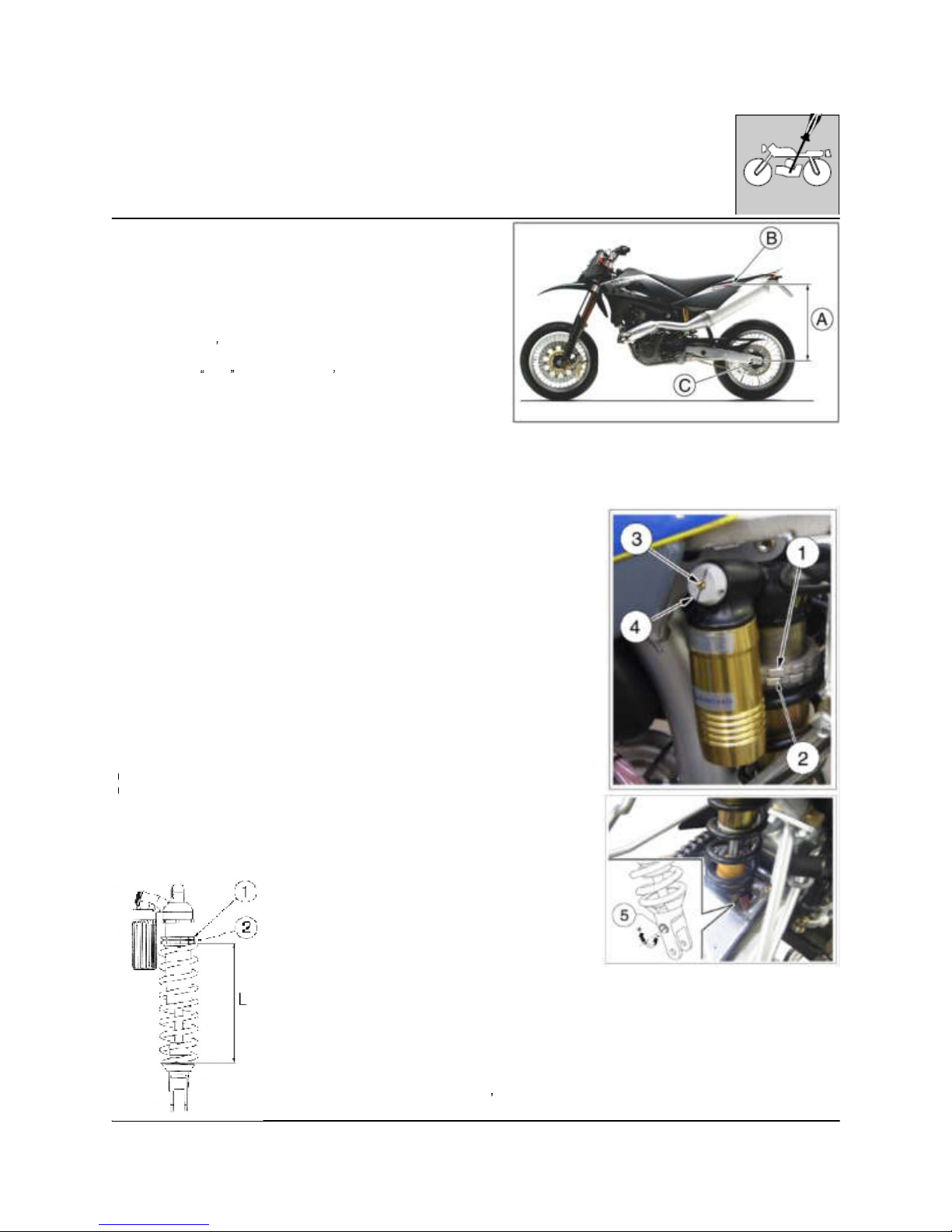
Adjusting the shock absorber sag
The rear shock absorber must be adjusted according to the
rider weight and track conditions.
Proceed as follows:
1. With motorcycle in vertical position measure distance (A).
2. Take the normal riding position on the motorcycle with all
your riding apparel.
3. With somebody
s help, take the new distance (A).
4. The difference between these two measurements
constitutes the
SAG of the motorcycle s rear end.
Suggested SAG: 3.54 in. with cold shock absorber. 3.34÷3.42
in. with warmed up shock absorber.
5. To get the right SAG according to your weight, adjust the
shock absorber spring preload.
B: axis of the panel screw
C: axis of rear wheel pin
Rear shock absorber adjustm ent
Adjusting the shock absorber spring preload
Proceed as follows:
1- Remove "The rear frame with fender" as shown on page E.14.
2. Clean ringnut (1) and adjusting nut (2) of the spring.
3. Either with a hook wrench or an alum inum punch, loosen the ringnut .
4. Turn the adjusting nut as required.
5. When the adjusting operation is over, tighten the ringnut. (Torque for both
ringnuts: 5 Kgm ; 49 Nm; 36.2 ft/lb).
Shock absorber hydraulic brake adjustment
* A) COMPRESSION - Standard adjustment:
1) Low damping speed: maximum open (adjuster 3)
2) High damping speed: maximum open (adjuster 4)
In order to obtain an harder braking action turn the adjusters clockwise.
* B) EXTENSIO N - Standard calibration:
TE 610: -20 clicks ± 2 clicks
SM 610: -26 clicks ± 2 clicks
To reset the standard calibration, turn lower adjuster (5) clockwise until
reaching fully closed position.
Return then back for the mentioned clicks. In order to obtain a sm ooth
braking action, turn the register anticlockwise. Reverse the operation in order
to obtain a harder braking action
.
Standard pre-loaded length of spring:
234,5-237,5 mm (9.23-9.35 in.)
*: replace data on owner s manual no. 8000 A4860 (pages 120, 122)
http://husqy.forumsactifs.com
Page 40
16
SETTINGS AND ADJUSTMENTS
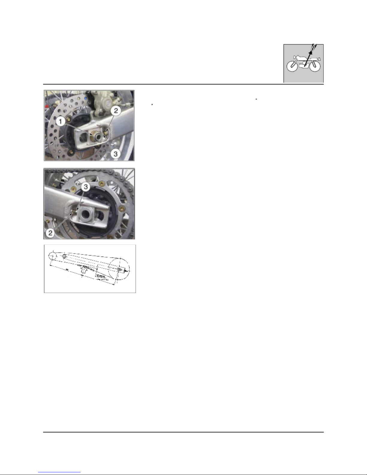
Drive chain adjustment
Carry out the cleaning operations as described in the periodical maintenance
card
. Check the chain tension adjusting and lubricate it if necessary.
The chain is adjusted correctly when the m otorcycle is in vertical position and
unloaded, as shown on figure. If not, adjust the chain as follows:
- loosen the nut (1) of the wheel axle;
- loosen the nuts (2) on both sides of the chain-adjusters then operate the
adjusting screws (3) till the correct tension is restored (make sure that both
the chain streighteners are aligned on the same notch);
- tighten the nuts (2) (22,5 Nm / 2,3 Kgm / 16.6 lb-ft);
- tighten nut (1) of the wheel axle (142 Nm/ 14,5 Kgm/ 104.8 lb-ft);
- check again the chain tension.
After the adjustment, always check the wheel alignm ent and tighten the wheel
axle fully. Before lubricating the chain clean it carefully. On dusty roads,
or in poor road conditions, m ore frequent lubrication is necessary.
http://husqy.forumsactifs.com
Page 41
1
GENERAL OPERATIONS
Section
http://husqy.forumsactifs.com
Page 42
2
GENERAL OPERATIONS
Table of Contents
FOREWORD
E. 3
Rem oval of saddle E. 4
Rem oval of side panels E. 4
Rem oval of air filter box and carburetor E. 5
Rem oval of conveyors and fuel tank E. 6
Rem oval of exhaust system E. 7
Rem oval of electrical connections and spark
plug cap
E. 8
Rem oval of cooling system hoses E. 8
Rem oval of cooling fan, radiators and coolant
expansion tank
E. 10
Rem oval of engine from the fram e E. 11
Rem oval of rear fram e w ith fender E. 12
http://husqy.forumsactifs.com
Page 43
3
GENERAL OPERATIONS
Forew ord
The operations described in this section are referred to the removal of the engine from the motorcycle; further operations not directly connected to this scope are located at the end of the chapter.
http://husqy.forumsactifs.com
Page 44
4
GENERAL OPERATIONS
Rem oval of saddle
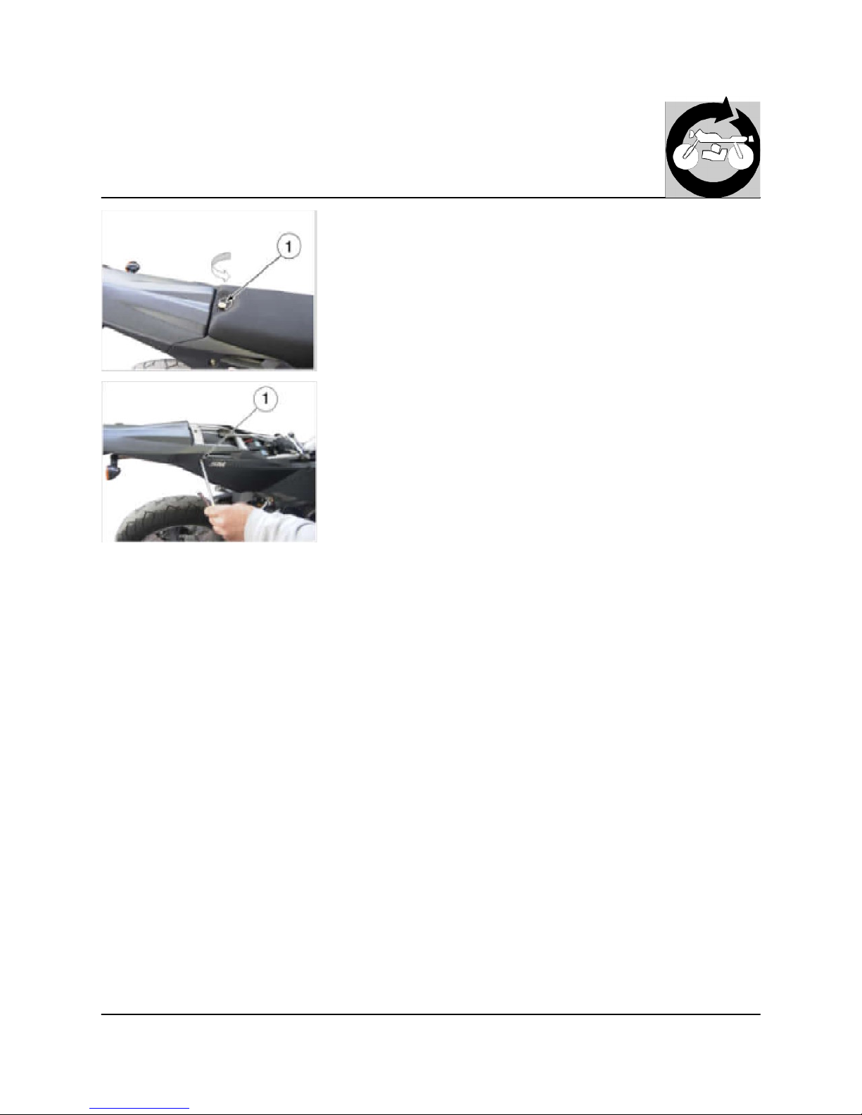
Turn counterclockwise the rear fastening pin (1) and remove the saddle.
Rem oval of side panels
- R.H. side panel
Remove the R.H. side panel rear fastening screw (1). Unhook the side panel
from the front side of the air filter box.
- L.H. side panel
Remove the L.H. side panel rear fastening screw. Unhook the front side of
the panel from the conveyor.
When reassembling, remember to fit bushes under the screws.
http://husqy.forumsactifs.com
Page 45
5
GENERAL OPERATIONS
Rem oval of air filter box and carburetor
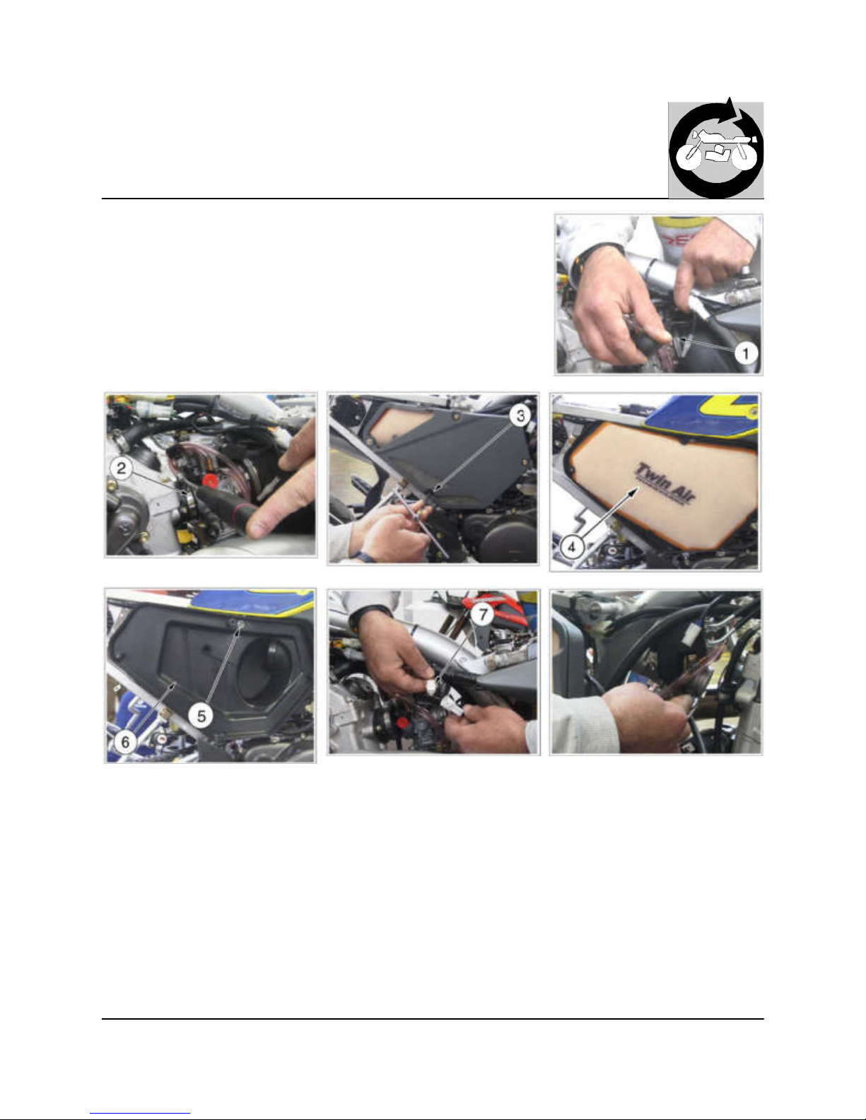
Loosen on the L.H. side the manifold clamp (1) on the carburetor then the
front clamp (2) on the cylinder head;
- remove the four screw (3) that fasten the air filter box cover, the air filter (4),
the screw (5) and the air filter box (6);
- remove the breather hose from the air filter box;
- push lightly, using a little screwdriver, on the T.P.S. connector (7) located on
the carburetor in order to detach it from the main wiring harness;
- remove the carburetor.
http://husqy.forumsactifs.com
Page 46
6
GENERAL OPERATIONS
Rem oval of conveyors and fuel tank
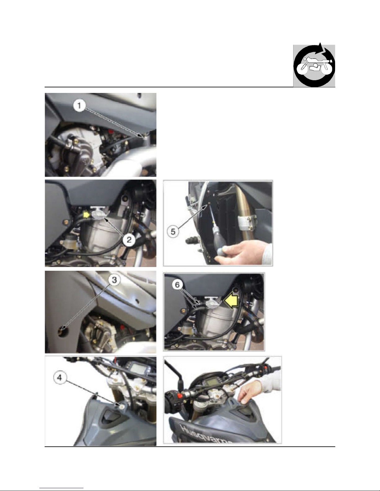
Close the L.H. side fuel cock and place the R.H. fuel cock (2) on OFF
position;
- remove the spoilers fastening screws (3);
- remove the fuel tank front fastening screw (4);
- remove the radiator guards front fastening screws (5);
- detach the two hoses (6) from the R.H. fuel cock and detach the fuel feeler
gauge connector from the main wiring harness;
- remove the fuel tank.
http://husqy.forumsactifs.com
Page 47
7
GENERAL OPERATIONS
Rem oval of exhaust system
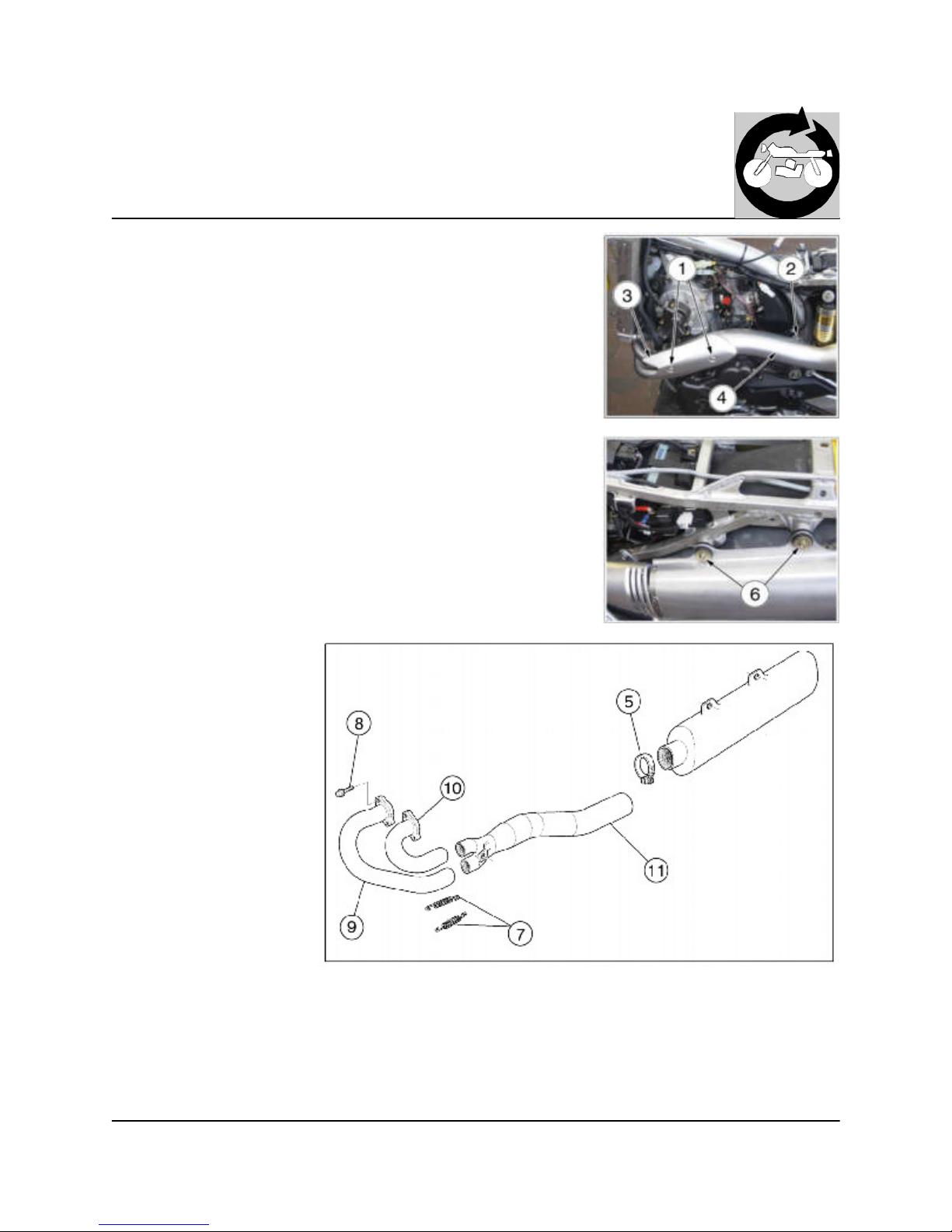
Remove the screws (1), (2) and the two guards (3) and (4) from the front exhaust
pipes and from the central exhaust pipe (NOTE: reassem ble the screws
(1) and (2) with "LOCTITE 243"). Loosen the clamp (5) that fastens the central
exhaust pipe to the exhaust silencer. Remove the two silencer fastening
screws (6). Remove the silencer. Remove the springs (7) that fasten the front
pipes to the central pipe.
Remove the screws (8), the front pipes (9) and (10) then the central pipe (11).
http://husqy.forumsactifs.com
Page 48
8
GENERAL OPERATIONS
Rem oval of electrical connections and spark plug cap
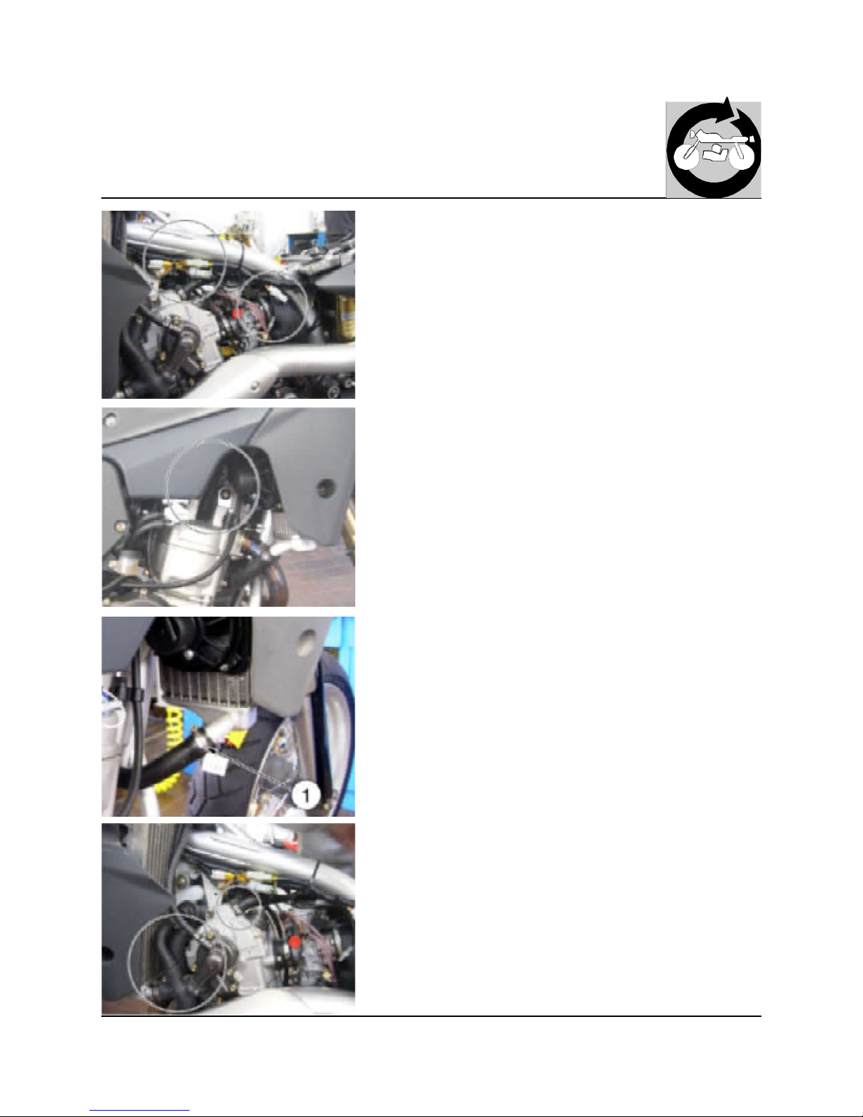
Detach the electrical connections from the engine to the m ain wiring harness
(starting motor cable, ground cable battery-engine, generator cables, neutral
switch cable) and the spark plug cap.
Rem oval of cooling system hoses
Remove the radiator cap, loosen the lower clamp (1), remove the hose then
drain the coolant.
Loosen the clamps on the others hoses and detach the hoses from the
engine.
Remove, on the L.H. side, the breather hose between teh cylinder head and
the fram e.
http://husqy.forumsactifs.com
Page 49
9
GENERAL OPERATIONS
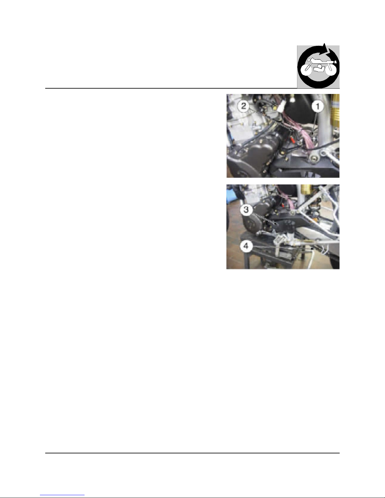
On the L.H. of the engine, remove the breather hose (1), the clutch
cable (2),
the pinion guard (3), the m aster link and the rear chain (4).
http://husqy.forumsactifs.com
Page 50
10
GENERAL OPERATIONS
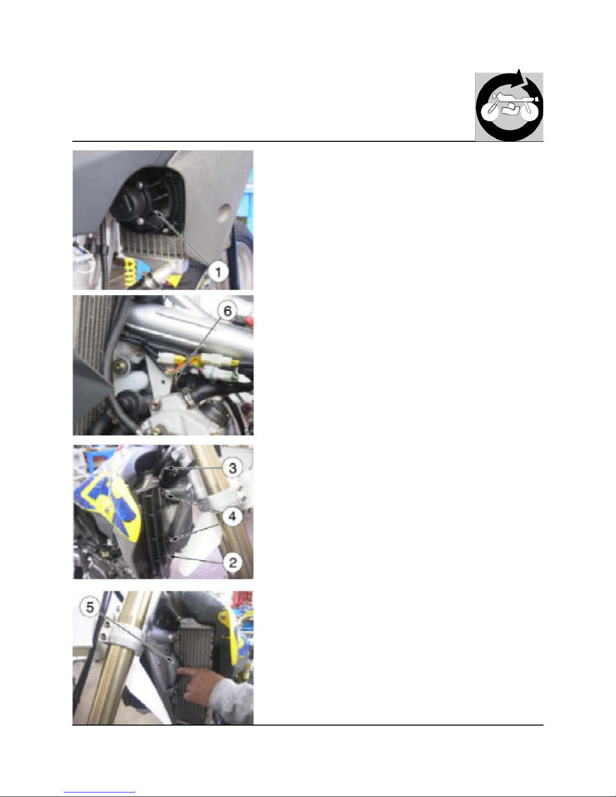
Cooling fan, radiators and coolant expansion tank rem oval
Disconnect the cooling fan (1) from the main wiring harness; rem ove the fan
from its holding plate. Detach the thermoswitch (6) from the main wiring
harness.
Remove the grid (2), detach the breather hose (3), rem ove the two screws
(4) and the R.H. radiator.
Repeat the sam e operations to rem ove the L.H. radiator then also rem ove
the coolant expansion tank (6).
http://husqy.forumsactifs.com
Page 51
11
GENERAL OPERATIONS
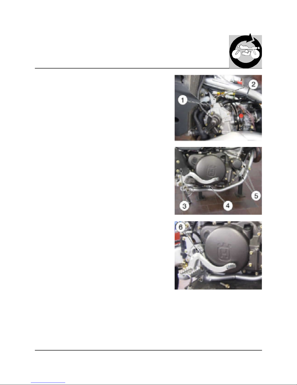
Engine rem oval from the frame
Remove the upper engine fastening screw (1) then the plate (2) from the
engine.
Remove the rear brake pump guard (3).
Remove the engine fastening screws (4) and (5) then the swing arm pivot (6)
(remove the respective nuts on the L.H.-SIDE).
Lift the engine and extract it sideways.
http://husqy.forumsactifs.com
Page 52
12
GENERAL OPERATIONS
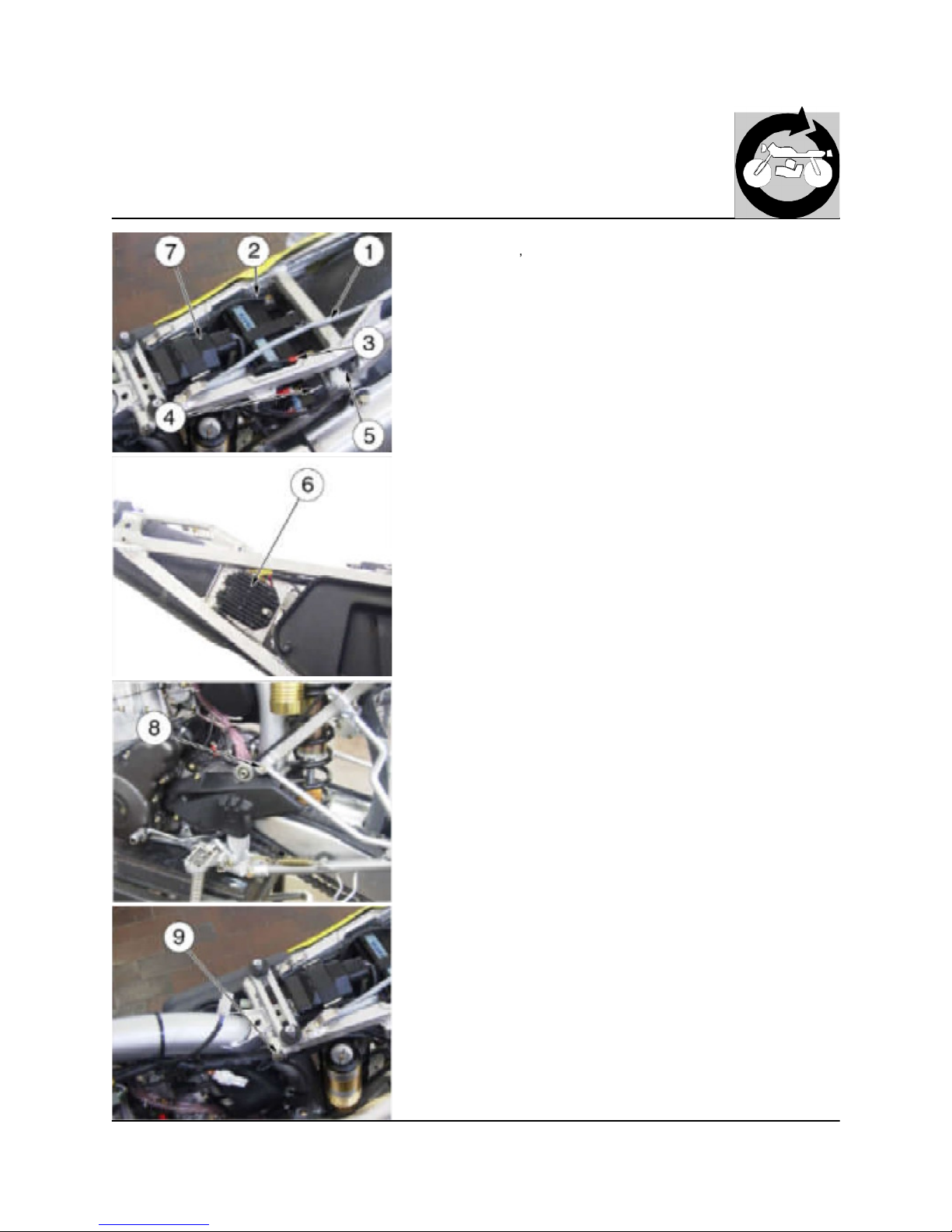
Rem oval of rear frame with fender
This operation doesn
t concern the engine removal from the motorcycle.
Remove the saddle, the side panels, the air filter box, the fuel tank, the exhaust silencer and the rear brake pump guard as shown on pages E.4, E.5,
E.7, E.9, E.13.
Detach the rear tail light cable (1) connector from the main wiring harness.
Detach the battery cables (2) and (3): first rem ove the BLACK negative cable
(2) then the RED positive cable (3); when reassem bling, first connect the RED
positive cable (3) then the BLACK negative cable (2).
Cut the solenoid starter plastic clamps (4); remove the solenoid starter and the
flasher (5).
On the R.H. side detach the voltage regulator (6) connector from the main
wiring harness.
Without detaching the connection from the main wiring harness, rem ove the
electronic power unit (7) complete with elastic holder from the rear fram e.
On both sides, rem ove the lower fastening screw (8) of the passenger footrest
holder: this screw fastens the lower side of the rear frame also.
Pull back the rear frame, with the rear fender, and remove it from the main
frame.
http://husqy.forumsactifs.com
Page 53
1
ENGINE DISASSEMBLY
Section
http://husqy.forumsactifs.com
Page 54
2
ENGINE DISASSEMBLY
Table of Contents
Disassem bly of gear lever
F.4
Disassem bly of alternator side cover F.5
Disassem bly of alternator F.6
Disassem bly of the w ater pump body F.7
Disassem bly of cylinder head cover F.8
Disassem bly of cylinder head F.9
Disassem bly of valves F.10
Disassem bly of cylinder F.10
Disassem bly of piston F.11
Disassem bly clutch cover F.12
Rem oval of the starter m otor and holding
flange
F.13
Disassem bly of clutch F.14
Disassem bly if the gearbox control shaft F.15
Disassem bly of crankcase, crankshaft and lay
shaft
F.16
Disassem bly of the gearbox F.19
Disassem bly of the oil pum p F.20
Disassem bly of the stator F.20
Disassem bly of the crankshaft com ponents F.21
http://husqy.forumsactifs.com
Page 55
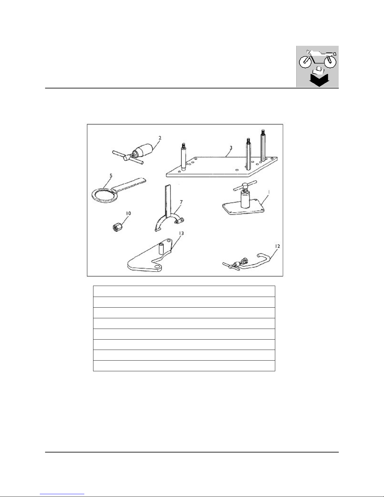
3
ENGINE DISASSEMBLY
1
8000 89743 Crankcase puller
2 8000 39523 Flyw heel puller
3 8000 90662 Engine holder
5 8000 39524 Clutch hub retaining w rench
7 8000 39522 Flyw heel disassembling w rench
10 8000 83254 Crankshaft guard
12 8000 39521 Valves assem bly and reassem bly tool
13 8000 90875 T.D.C. control tool
SPECIFIC TOOLS
http://husqy.forumsactifs.com
Page 56
4
ENGINE DISASSEMBLY
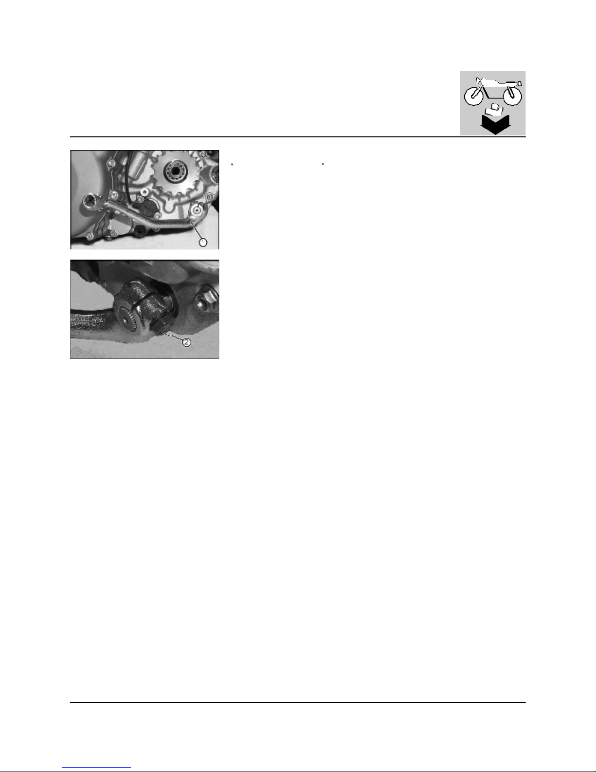
To facilitate the job, drain the oil from the engine (as described in the chapter
Settings and Adjustments , page D.5). Remove the spark plug and the gear control
lever.
Disassembly of gear lever
Make a mark on the shaft showing the position of the gear lever (1) to make the
reassembly easier. Loosen the screw (2) (10 mm wrench) and lift away the gear
lever.
http://husqy.forumsactifs.com
Page 57
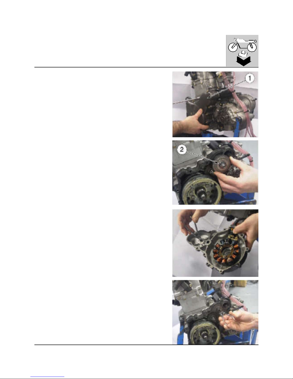
5
ENGINE DISASSEMBLY
Disassembly of alternator side co ver
Remove the cover (1) with the stator (8 mm wrench) and with the gasket.
Extract the gear with clutch (2).
Remove the two bushings from alternator cover and from starting motor holding flange.
http://husqy.forumsactifs.com
Page 58
6
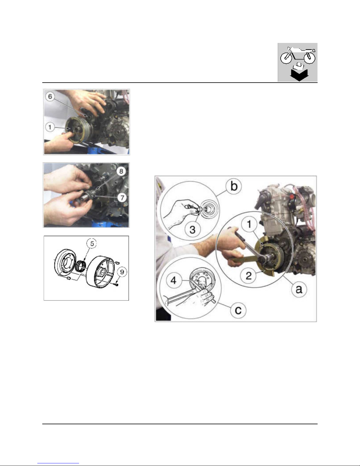
ENGINE DISASSEMBLY
Disassembly of alternator
a) Keep the fly wheel (1) steady using the tool (2) code 800039522,
rem ove the 24 m m nut and its washer.
b) Install the protection tool (3) code 800083524 on the crankshaft.
c) Install on the crankshaft the tool (4) code 800039523 and, holding
the outer body of the tool blocked with a hexagonal wrench, turn the
handle clockwise to remove the flywheel from the shaft.
Withdraw the flywheel complete of free wheel (5) and the m iddling
gear (6), then remove the key from the crankshaft cone.
Remove the roller cage (7) and the thrust washer (8); remove the
screws (9) (5m m w rench) and check the conditions of the freewheel:
the working races of the rollers m ust not be worm or damaged.
Check that the various gears are in good conditions.
http://husqy.forumsactifs.com
Page 59
7
ENGINE DISASSEMBLY
Disassembly of the water pump body
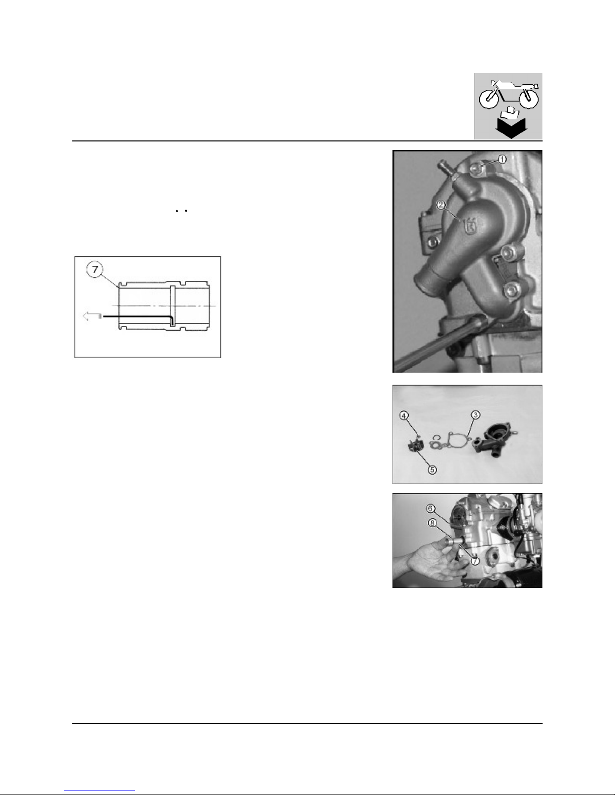
Remove five screws (1) (8 m m wrench) retaining the pump housing (2). Remove
the bushes (6). Remove the pump housing along with the packing (3). Replace
packing every time the pump is disassembled.
Remove the nut (4) (8 mm wrench) from the pump impeller (5). Lift away the
impeller.
Remove the spacer (7) with
O rings (8) from the water pump delivery hole. If
necessary, use an iron wire piece with a bent end to remove the spacer.
http://husqy.forumsactifs.com
Page 60
8
ENGINE DISASSEMBLY
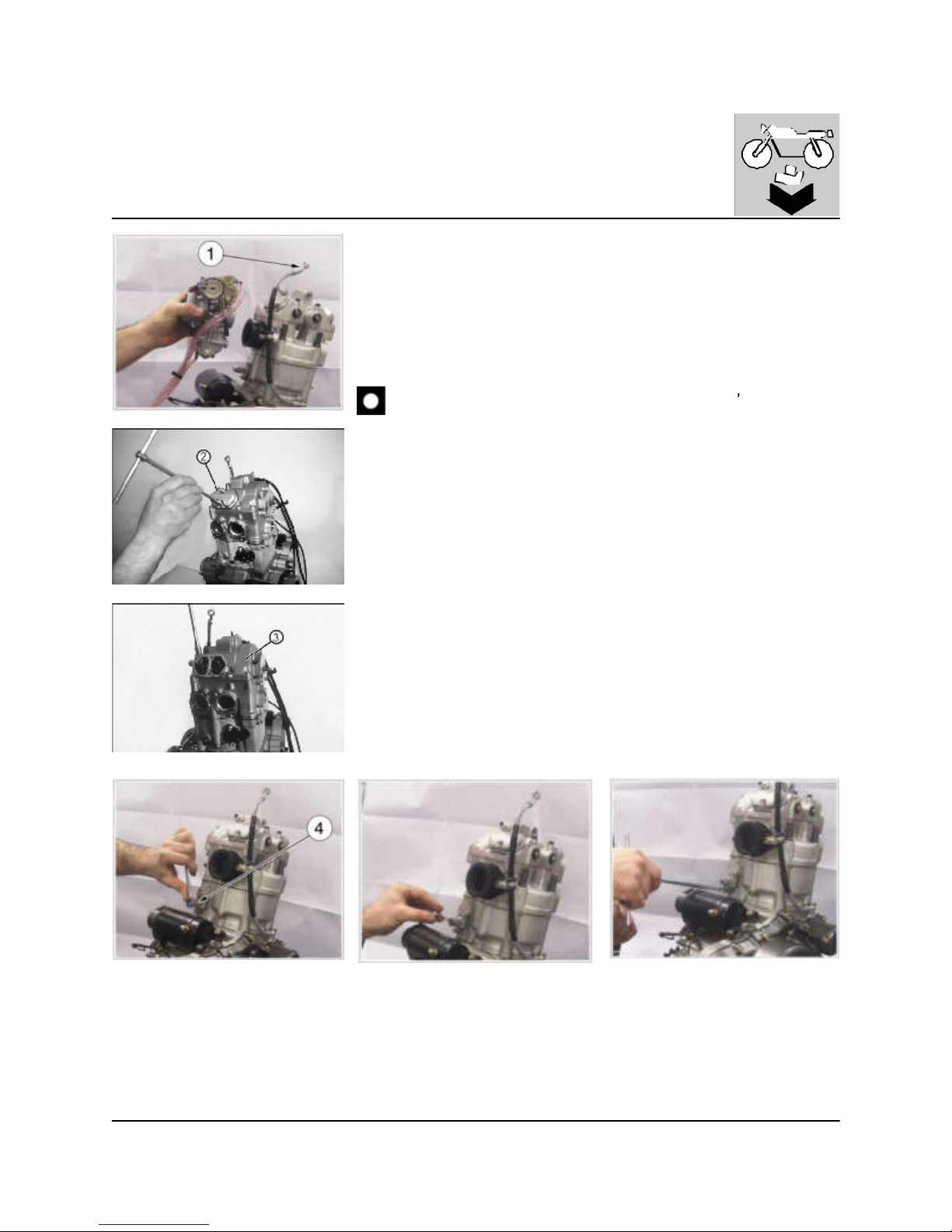
Disassembly of cylinder - head cover
Remove the union pipe (1) and the carburetor. Remove the valve register covers
(2) (8 mm wrench). Loosen all screws and rem ove the 2 adjusting covers (2) and
the cylinder head cover (3) (8 mm wrench). Remove the tensioner (4): remove the
central screw (10 mm wrench: pay attention to the spring during the nut rem oval),
the spring, the two side screws (8 mm wrench) and the tensioner. Take the piston
to T.D.C. at the end of the compression phase, with the tool cod. 800090875 as
described at chapter "Adjustments" (page D .5).
The cylinder head cover is leaded by centering bush. Don
t let them
falling.
http://husqy.forumsactifs.com
Page 61
9
ENGINE DISASSEMBLY
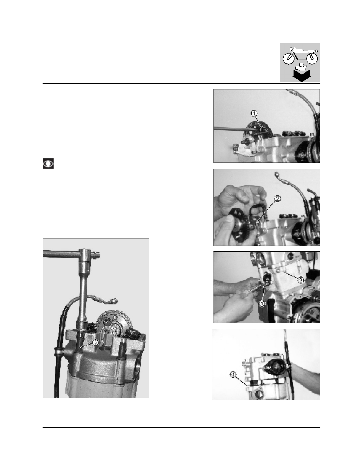
Disassembly of cylinder head
Remove the two cam shaft gear screws (1) (5 mm wrench).
Rotate the gear (1); to rem ove the cam chain, m ove the gear outwards.
Use a hook iron wire to recover the cam chain.
Remove the cam shaft (2) with the decompressor.
Remove the two nuts (1) from the cylinder (13 mm wrench) and the two
screws (2) on L.H. side (5mm wrench).
Remove the four head nuts (3) (11m m wrench).
Lift off the cylinder head.
Remove the gasket (4) and use a new gasket at reassembly.
Attention at the centering bushes betw een cylinder head and
cylinder.
http://husqy.forumsactifs.com
Page 62
10
ENGINE DISASSEMBLY
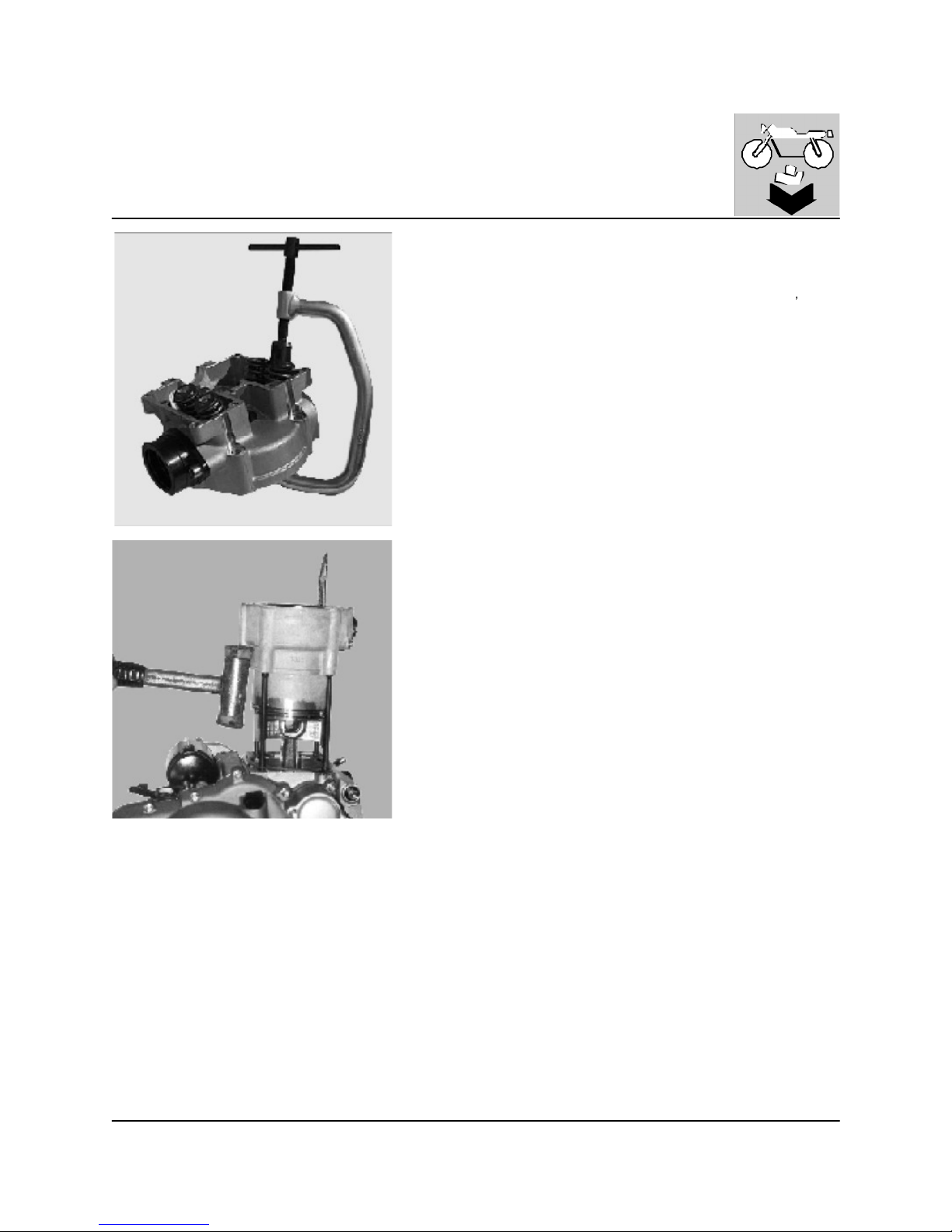
Disassembly of valves
Use valve spring compressor 8000 39521 to remove the valves. Be careful
not to damage the gasket surfaces or the combustion chamber of the cylinder head. Make sure that the valve spring compressor always is straight.
Otherwise the valve stem can be bent. To prevent loss of tension, don
t compress the valve springs m ore than necessary.
Mark all parts, so that they can be reassembled correctly. If the valve cotters
have made a burr on the valve stem, remove it before rem oving the valve.
Disassembly of cylinder
Lift off the cylinder. Tap carefully the existing bosses with a m allet.
http://husqy.forumsactifs.com
Page 63
11
ENGINE DISASSEMBLY
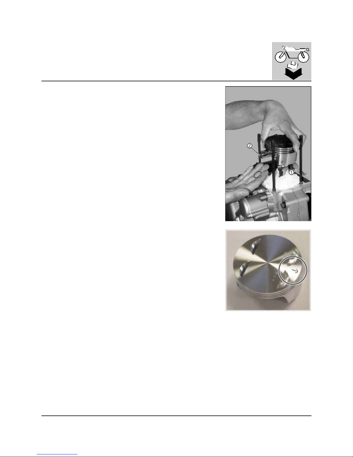
Disassembly of piston
Hold the piston and cover the crankcase with a clean rag.
The piston (1) is marked with an arrow on the exhaust side, in order to correctly
reassemble it.
Remove a piston pin keeper and press out the piston pin (2). Rem ove the piston.
http://husqy.forumsactifs.com
Page 64
12
ENGINE DISASSEMBLY
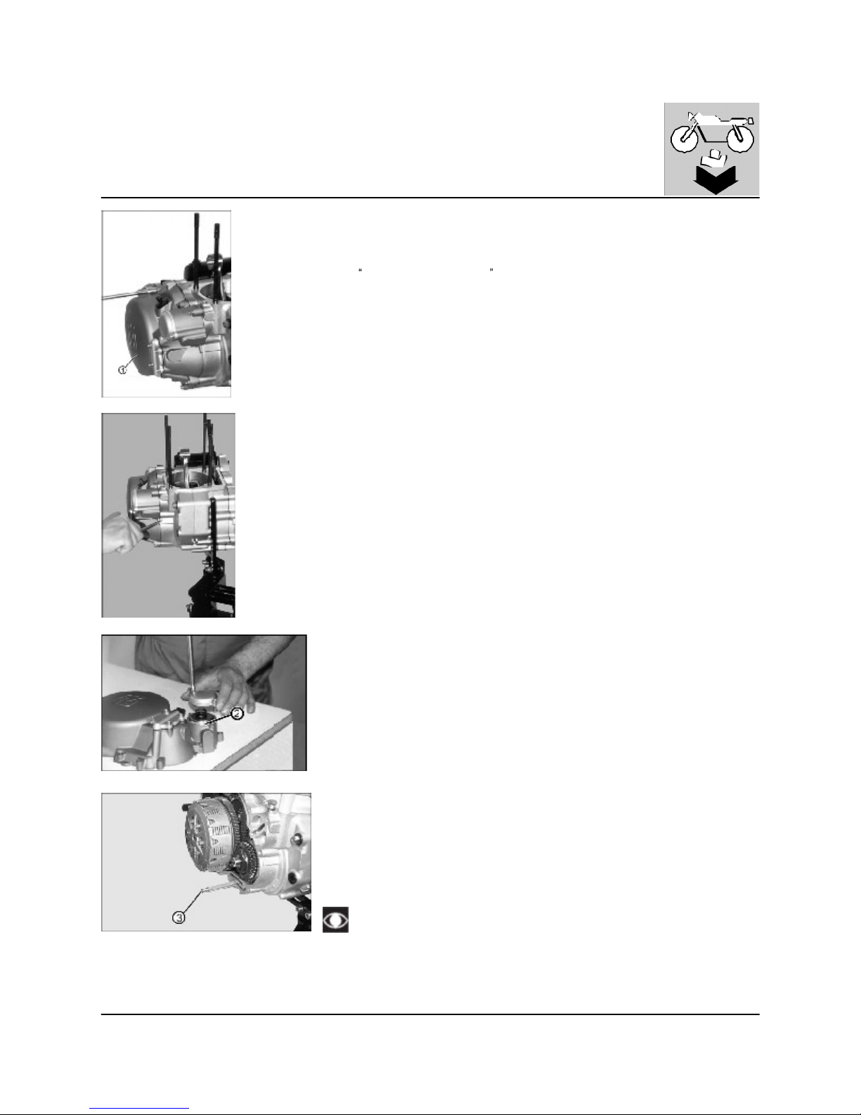
Disassembly clutch cover
Remove all screws (13 pcs.) holding the clutch cover (1). Remove the clutch cover
(in order to remove the cover, use a screwdriver).
Remove the oil screens (2, 3) and clean the filter (3) in accordance with the
instruction at chapter
Settings and Adjustments (page D.6).
Pay attention to the filter (3) reassembling sense.
http://husqy.forumsactifs.com
Page 65
13
ENGINE DISASSEMBLY
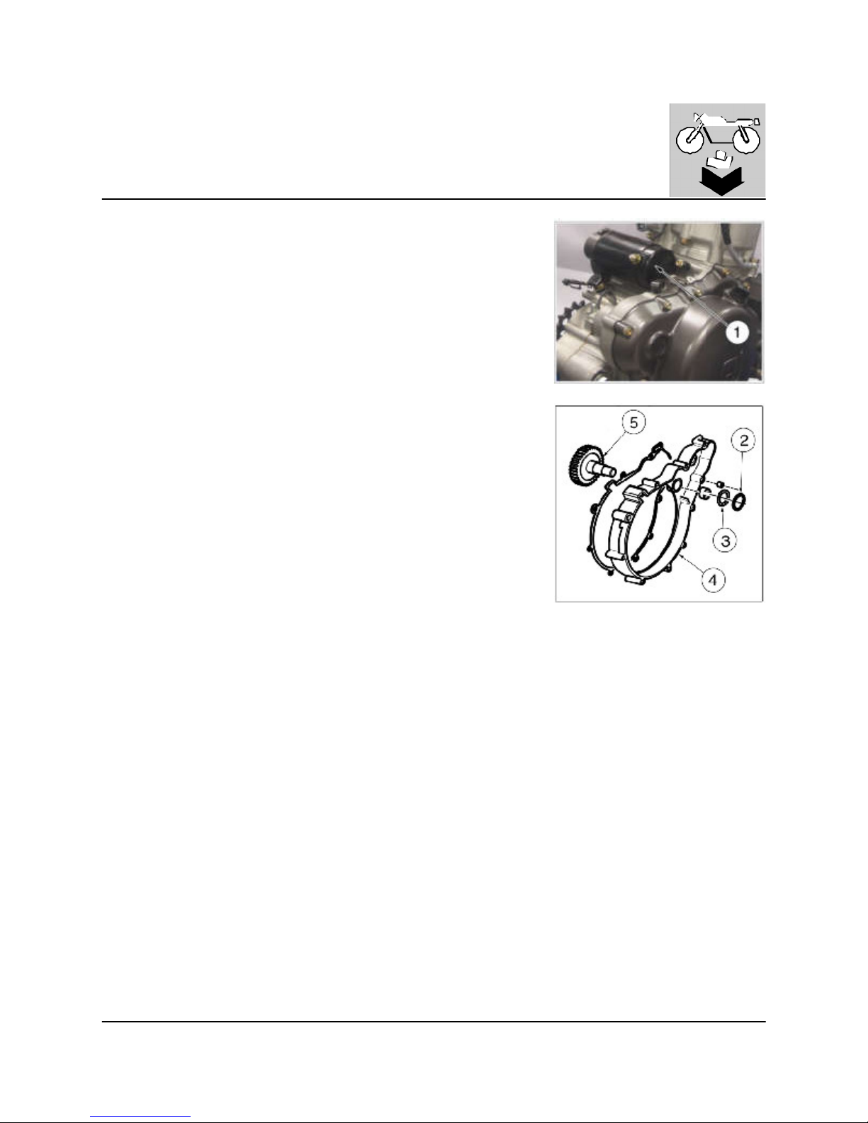
Rem oval of the starting m otor and holding flange
Remove the two fastening screws (8 mm wrench) and the starting motor (1).
Remove: retaining ring (2), washer (3), flange (4) and related gasket (carefully
using a mallet on the existing bosses) and the second idle gear (5).
http://husqy.forumsactifs.com
Page 66
14
ENGINE DISASSEMBLY
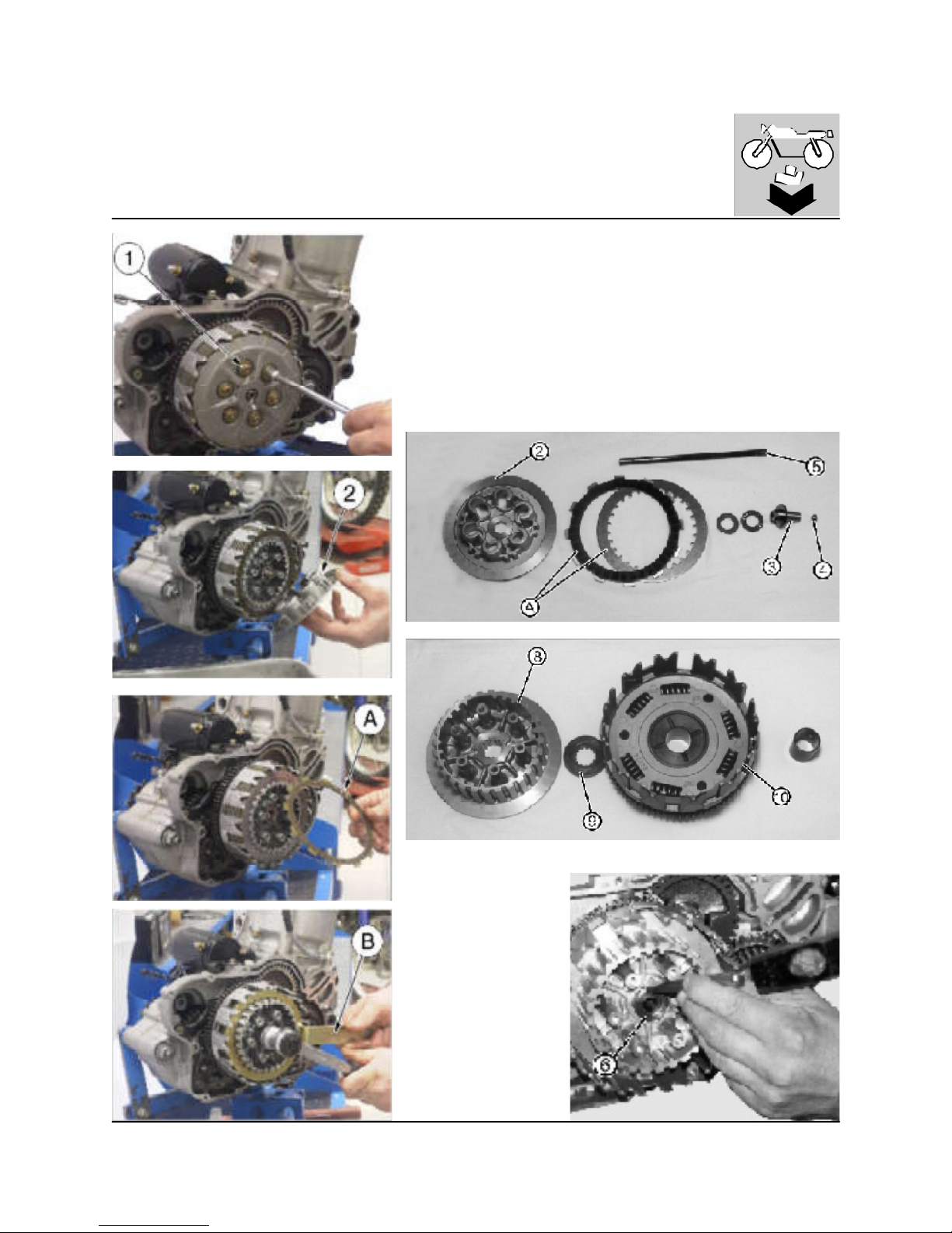
Disassembly of clutch
Set an aluminum shim am ong prim ary transmission teeth (in order to prevent
its rotation). Use a 8 mm wrench to loosen the six screws (1) which fix clutch
springs. Remove washers, springs, spring pressure plate (2), washer, axial
bearing, and disc pack (A). From primary shaft gearbox, recover rod (3), ball
(4), and pressure plate (5).
Straighter the safety washer (6) on the nut of the discs hub. Hold the clutch
hub steady with the tool (B) Code 800039524 and remove the nut (7) with a
27 m m. wrench. Remove the clutch hub (8), the grooved spacer (9), the
clutch bell (10).
http://husqy.forumsactifs.com
Page 67
15
ENGINE DISASSEMBLY
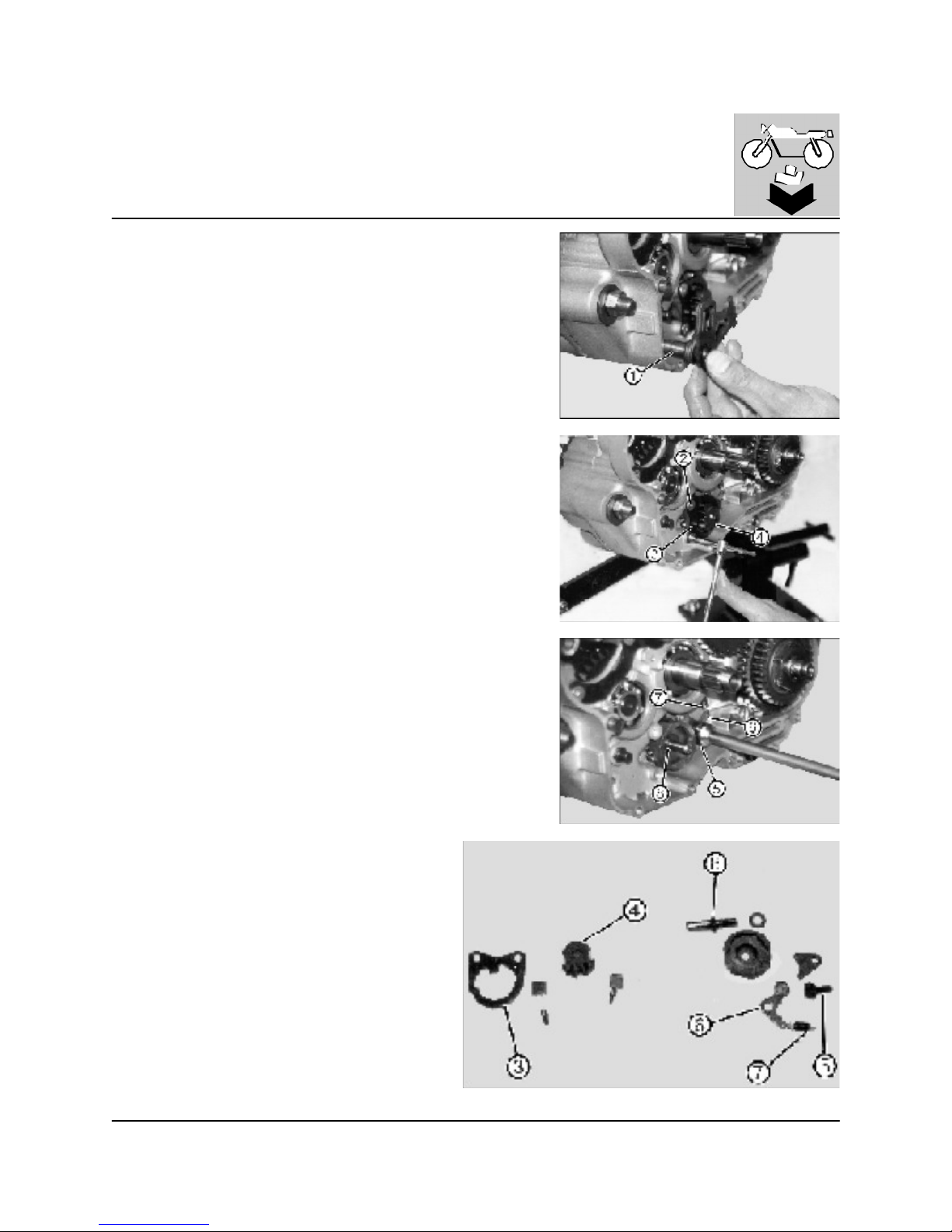
Disassembly if the gearbox control shaft
Withdraw the rack and the connected shaft (1)
Remove the two 4 mm Allen screws (2) and remove the plate (3) sprocket of
the gear sector (4).
Using a 13 mm pipe wrench remove the screw (5) that secures the gear
speed (6) setting pawl, including the spring (7) and the plate.
Remove the screw (8) with a 12 m m wrench
http://husqy.forumsactifs.com
Page 68
16
ENGINE DISASSEMBLY
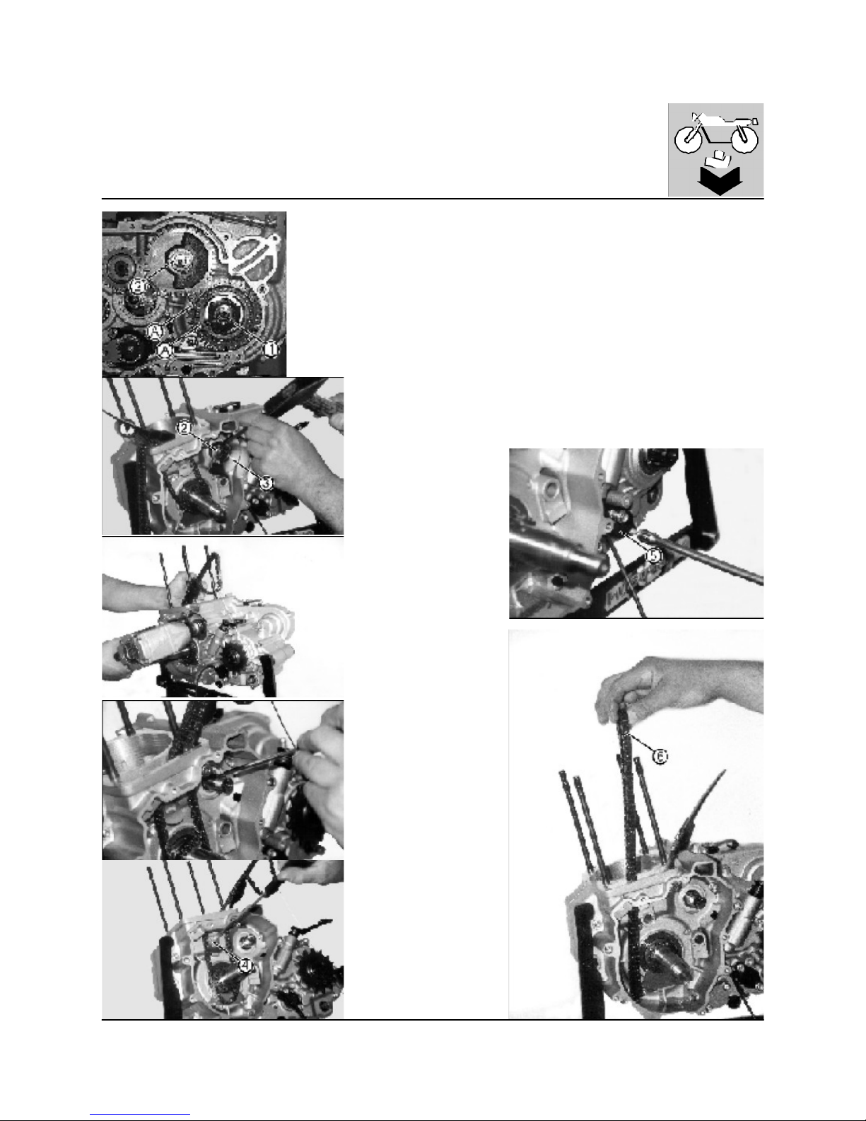
Disassembly of crankcase, crankshaft and lay shaft
Perform the following on the R.H. crankcase, proceed as follows.
Straighten the safety washers; rem ove the nuts (1, 2) securing the crankshaft
and lay shaft (remove the layshaft fastening nut on L.H. side too).
Remove the lay shaft counterweight (3) and the key.
Remove the two gears (A) on the crankshaft and the key.
Remove the two screws locking the blade valve (4) and remove it.
Using a 8 mm wrench, unlock the 2 screws then remove the neutral sensor
(5) with seal ring, pin and spring.
Withdraw the timing chain (6).
http://husqy.forumsactifs.com
Page 69
17
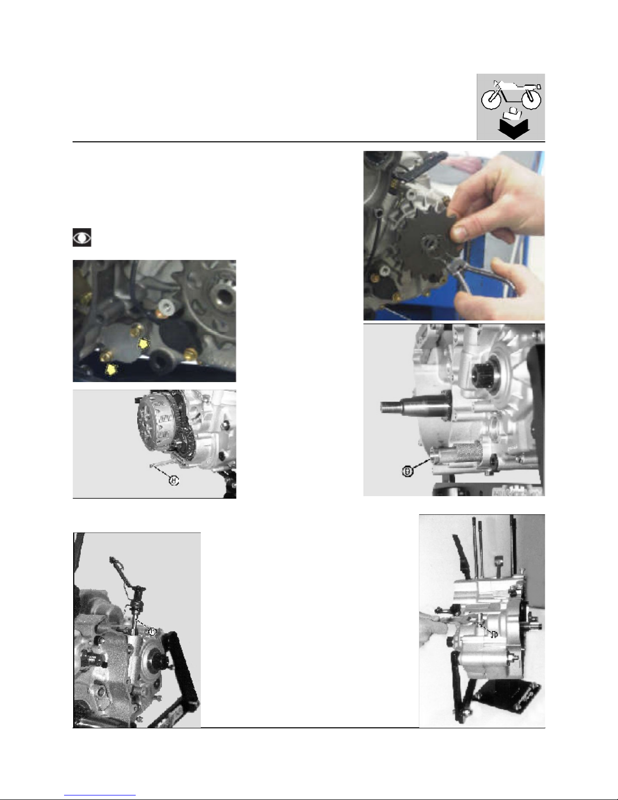
ENGINE DISASSEMBLY
Remove the seeger ring (7) and withdraw the pinion, operating on the L.H.
crankcase.
If not previously removed, remove the R.H. oil screen (8) and the L.H. oil
screen
(9): for this one, remove the cover (8 mm wrench).
Remove the oil vapor recovery duct (10) using a 19 m m wrench.
Remove the clutch control rod (11).
Pay attention to the filter (8) reassem bling sense.
http://husqy.forumsactifs.com
Page 70
18
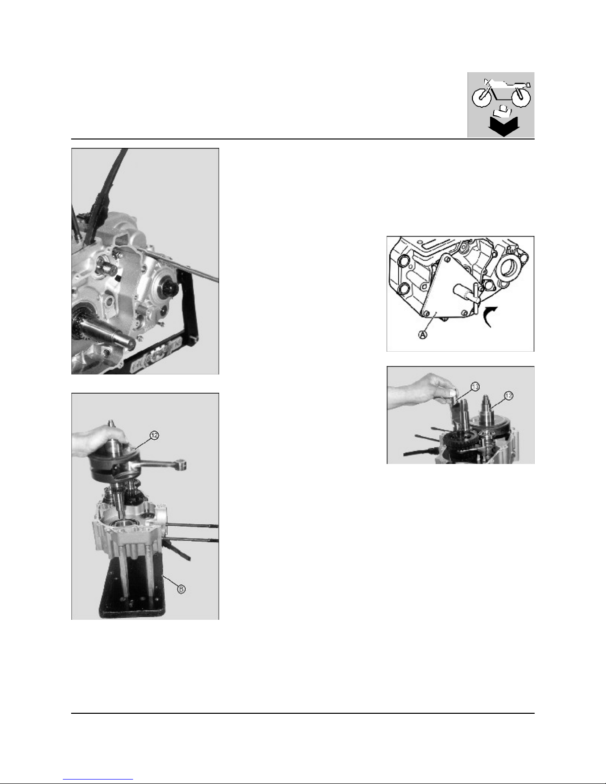
ENGINE DISASSEMBLY
Remove the screws locking the L.H. to the R.H. crankcase.
Install the special tool (A) n° 800089743 and open the crankcases, levering
on the crankshaft
Separate the crankcases with the gearbox assembly on the left one.
Place the left half-case on the support (B) cod. 800090662.
Withdraw the crankshaft (12) and the lay shaft (13).
http://husqy.forumsactifs.com
Page 71
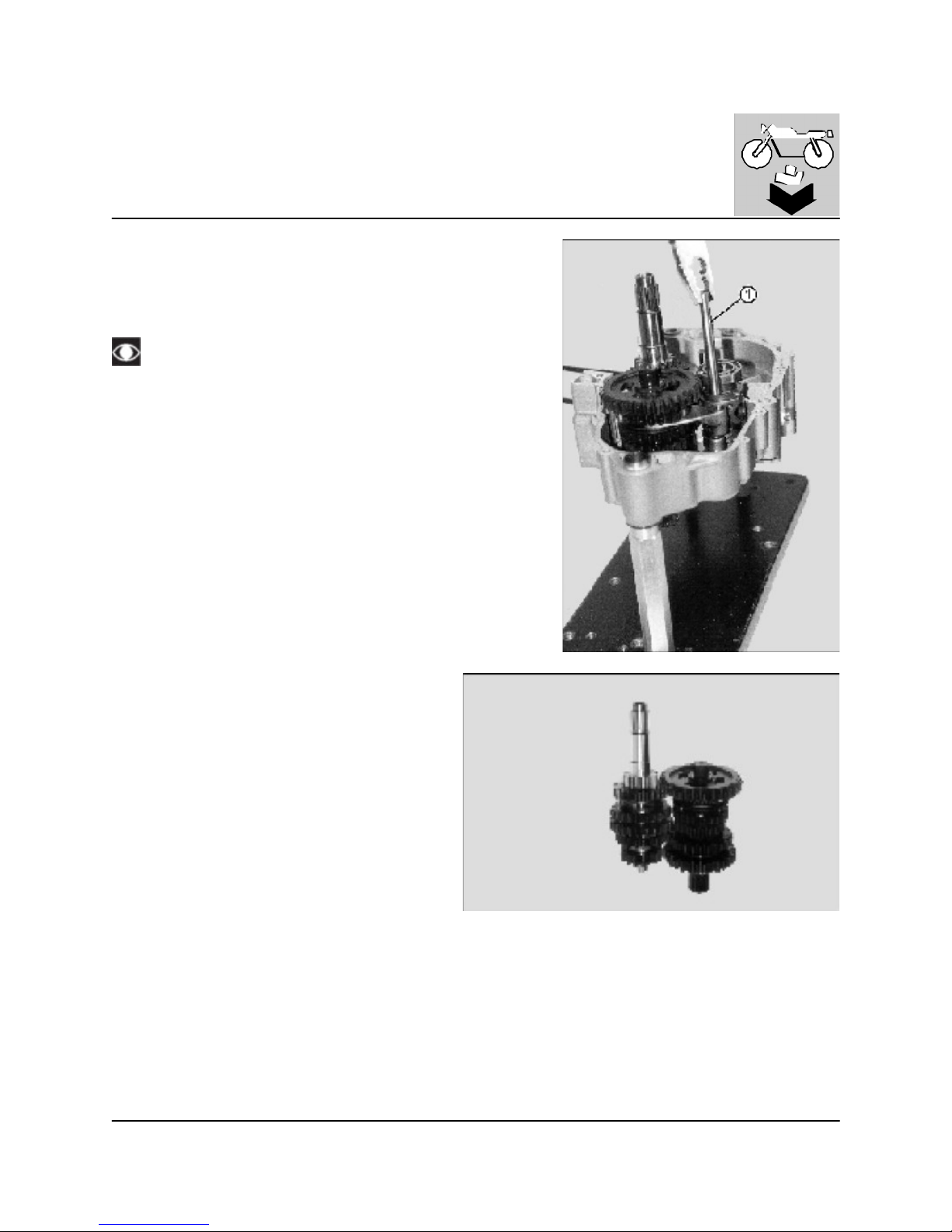
19
ENGINE DISASSEMBLY
Disassembly of the gearbox
Using pliers remove the rods (1) on which the forks are hinged.
Remove the forks.
Remove the gear box control group, if not previously done.
Pay attention to the mating profiles of the gear box control.
Remove the gear box control as a group.
http://husqy.forumsactifs.com
Page 72
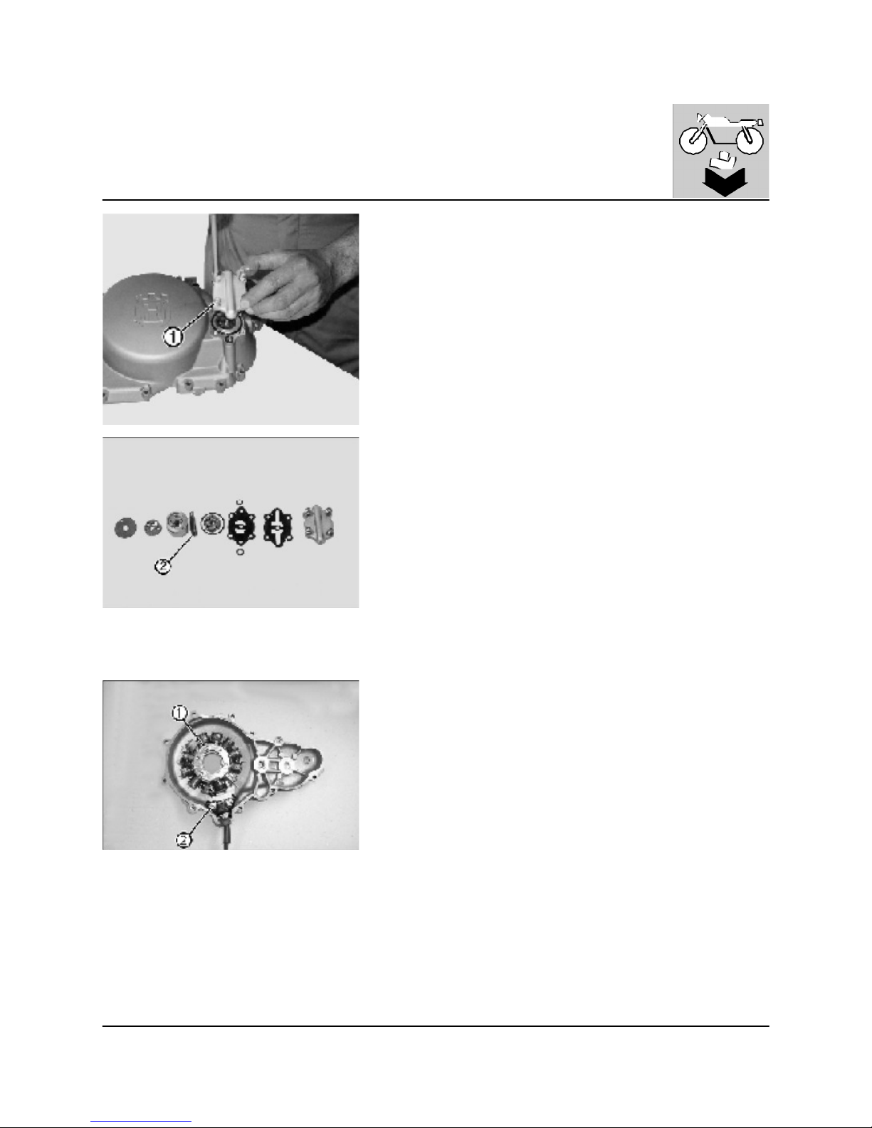
20
ENGINE DISASSEMBLY
Disassembly of the oil pump
From the previously rem oved clutch cover, rem ove the four oil pump fastening screws (1) (8 mm wrench) that secure the cover, then rem ove all the
parts up to the oil pum p drive shaft (2).
Disassembly of the stator
From the ignition cover removed before rem ove the five Allen screws [(three
6 m m (1) and two 4 mm(2)], then remove the stator and the pick-up from the
L.H. cover
http://husqy.forumsactifs.com
Page 73
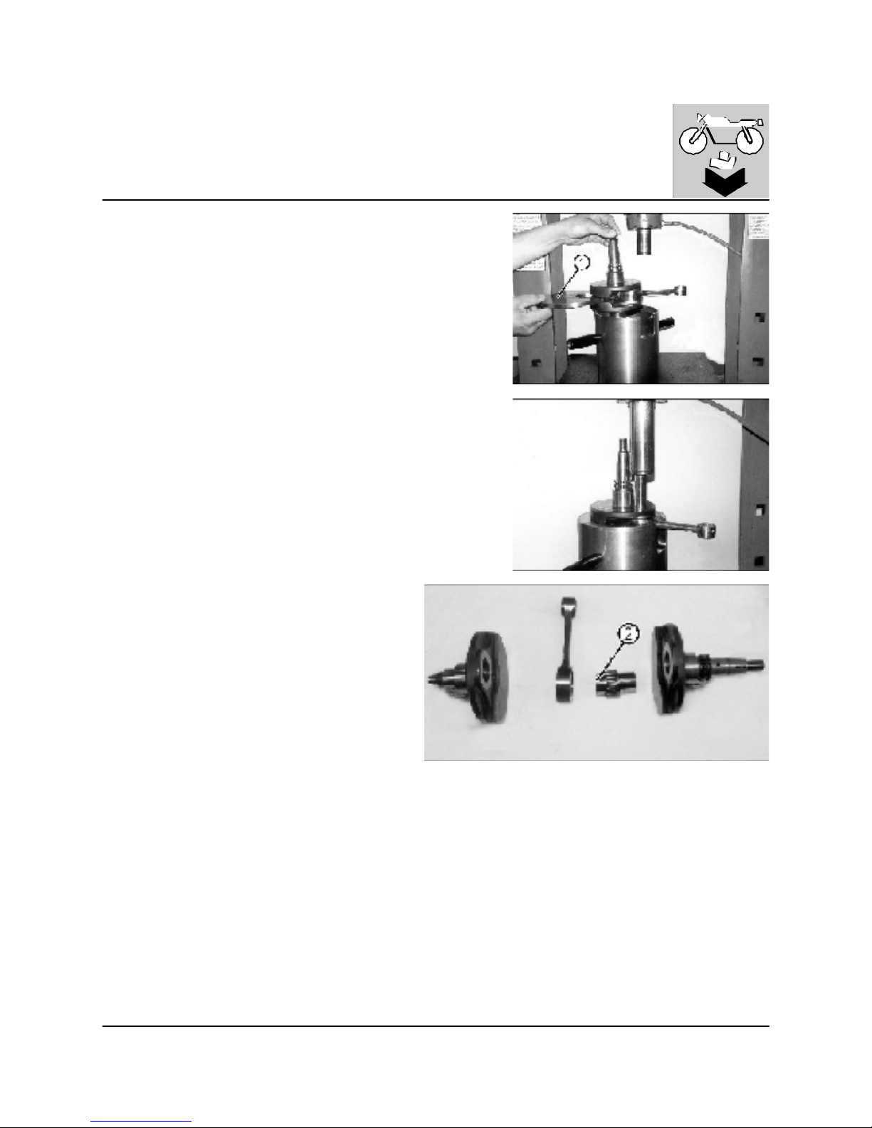
21
ENGINE DISASSEMBLY
Disassembly of crankshaft components
Insert a plate (1) between the two flywheel halves.
Using a press, rem ove the connecting rod pin, from one of the flywheel
halves.
Remove the connecting rod and needle bearing.
Turn the flywheel over half and press out the crankpin (2).
Remove the threaded plug and clean connecting rod pin.
http://husqy.forumsactifs.com
Page 74

22
http://husqy.forumsactifs.com
Page 75

1
ENGINE OVERHAULING
Section
http://husqy.forumsactifs.com
Page 76

2
ENGINE OVERHAULING
Table of Contents
Cleaning of components
G.4
Assemblies G.4
Cylinder head G.5
Valve seat G.5
Replacing oversize valves G.6
Valve guides G.6
Replacing the valve guide G .7
Valve G.7
Valve spring G.8
Installation of valves G.8
Inspection of rocker arm G.9
Replacem ent of rocker arm bushing G.9
Cam roller replacem ent . G.10
Cam shaft G .10
Timing chain and gears G.11
Timing chain stretcher sliding G.11
Cylinder G.12
Piston G.12
Cylinder piston fitting G.12
Piston diameter G.12
Gudgeon pin G.12
Gudgeon pin-connecting rod small end
clearance
G.13
Piston rings G.13
Piston rings-cylinder clearance G.14
Piston rings thickness G.14
Piston ring-piston rings groove clearance G.14
Connecting rod big end radial clearance G.15
Connecting rod big end axial clearance G.15
Balance countershaft G .15
http://husqy.forumsactifs.com
Page 77
3
ENGINE OVERHAULING
Table of Contents
Crankshaft G.15
Crankshaft run-out G.15
Replacing the small end bush G.16
Clutch unit G.16
Clutch housing-friction disc clearance G.17
Clutch spring G.17
Gear selector fork and gearing G.17
Fork drum - fork pins coupling G.18
Oil pum p G .19
Carburetor overhauling G.20
Carburetor setting G .21
http://husqy.forumsactifs.com
Page 78
4
ENGINE OVERHAULING
Cleaning of components
All components m ust be cleaned with gasoline and dried with compressed air.
During this operation inflam m able vapors burst and metal particles m ay be violently ejected.
Consequently, it is recommended to work in a room free from bare flames or sparks and that the operator
wears goggles.
SPECIFIC TOOLS
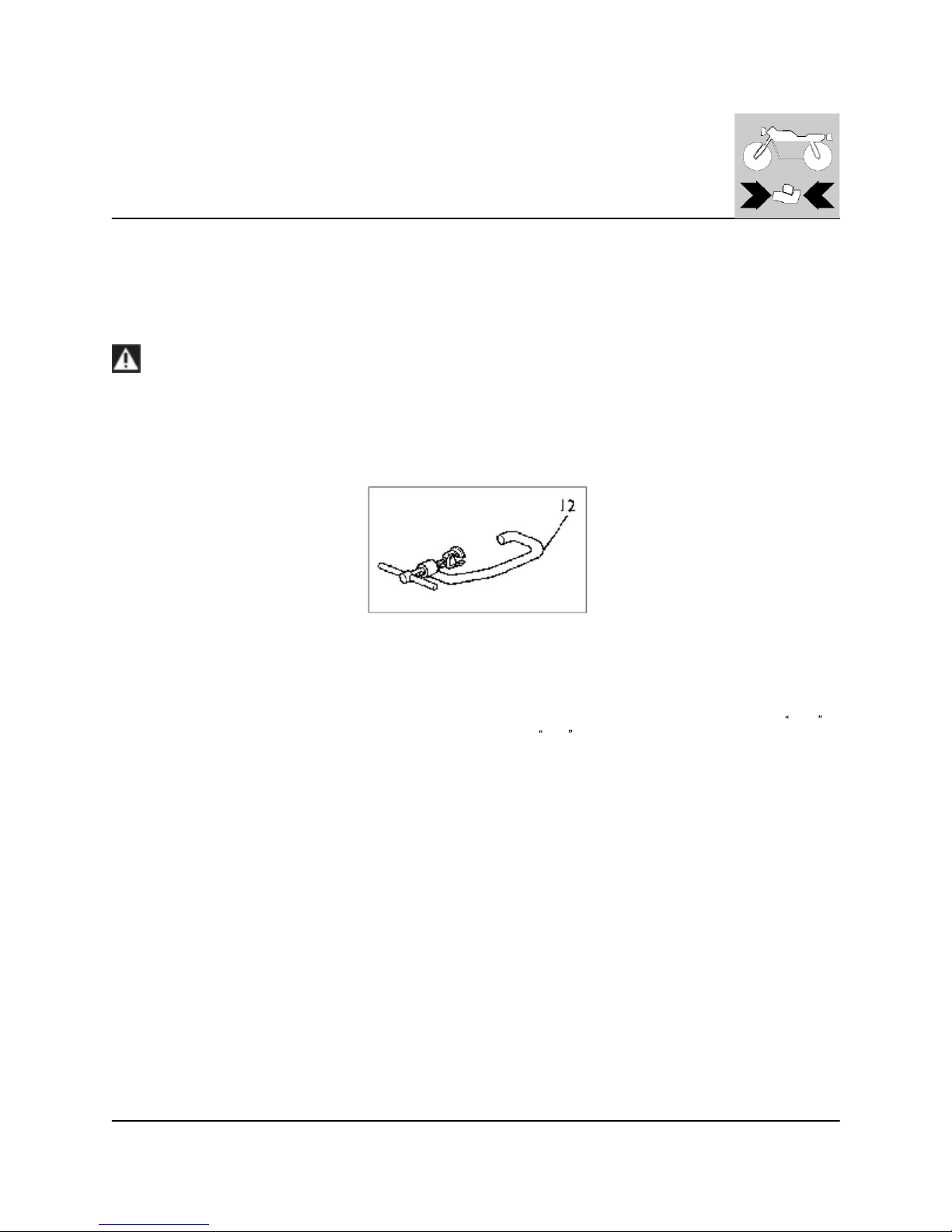
12- (8000 39521) Valves assembly and reassembly tool
Assemblies
For a good and efficient engine operation, it is essential that all assemblies are within the tolerances prescribed. In fact, a
close
assembly causes seizures as soon as the moving members heat up; while a
wide assem bly causes vibrations which in addition
to being noisy accelerate the wear of the moving components.
http://husqy.forumsactifs.com
Page 79
5
ENGINE OVERHAULING
Cylinder head
Remove carbon deposits from the combustion chamber using a rounded
scraper.
Do not use a sharp tool to avoid valve seats and spark plug thread
damaging.
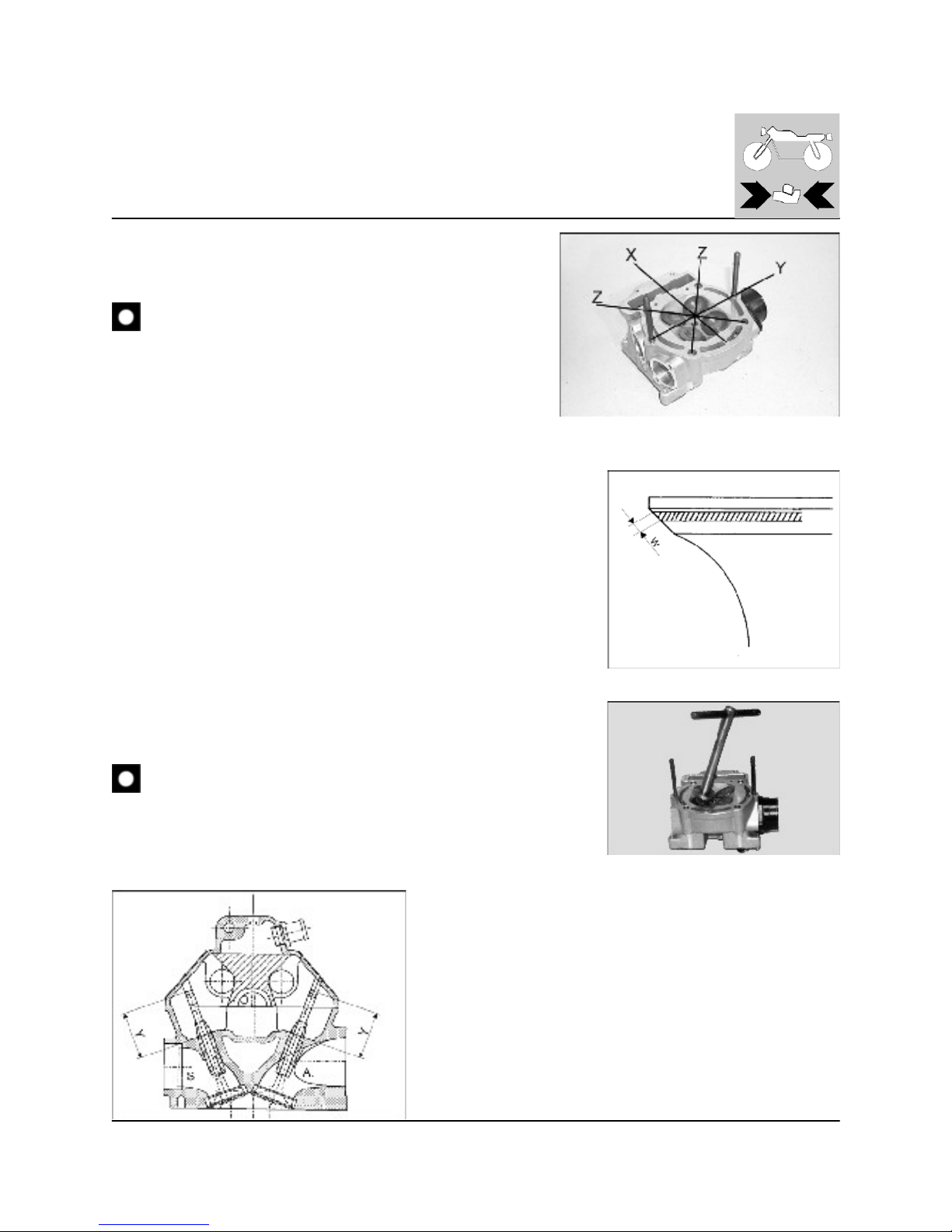
Check the machined surfaces of the cylinder head using a straight edge and a
feeler gauge taking readings at the points shown in the figure. If the reading at
any point is greater than the limit prescribed then regrind the contact surface
with the cylinder.
Cylinder head distortion limit: 0.0019 in.
Valve seat
This should pocketed or recessed and there should be no traces of cracks or
pitting. To check if the seat is damaged proceed as follows:
- Cover the valve seat with a uniform layer of red lead paste.
- Fit the valve into its seat and rotate a few tim es so that it leaves an impression
in the paste. During this operation hold the valve stem straight with a chuck
vice.
- The im pression left in the paste on the valve seat should be continuous without
breaks and the width of the impression (W ), which corresponds to the thickness
of the seat should be within the following lim its:
- W= 0.062÷0.070 in. (new engine: 0.039÷0.047 in.).
If the thickness is not within these lim its then re-cut the seat.
Proceed as follows:
Insert the guide pin of the miller and rotate a few times to rem ove any dirt from the
seat.
Using the same procedure as above check the valve seat. If it is dam aged or burn
it will require further m illing.
IM PORTANT: rem ove as little material as possible; this is to prevent the
valve stem from being too close to the rocker arm and thus altering the
contact angle of the valve.
S: EXHAUST
A: INT AKE
http://husqy.forumsactifs.com
Page 80
6
ENGINE OVERHAULING
Replacing oversize valves
Remove the seats by milling the rings. Take great care not to dam age the
seat locations in the head. C heck the diameter of the seat locations in the
head and choose the most suitable oversize valve seat taking into account
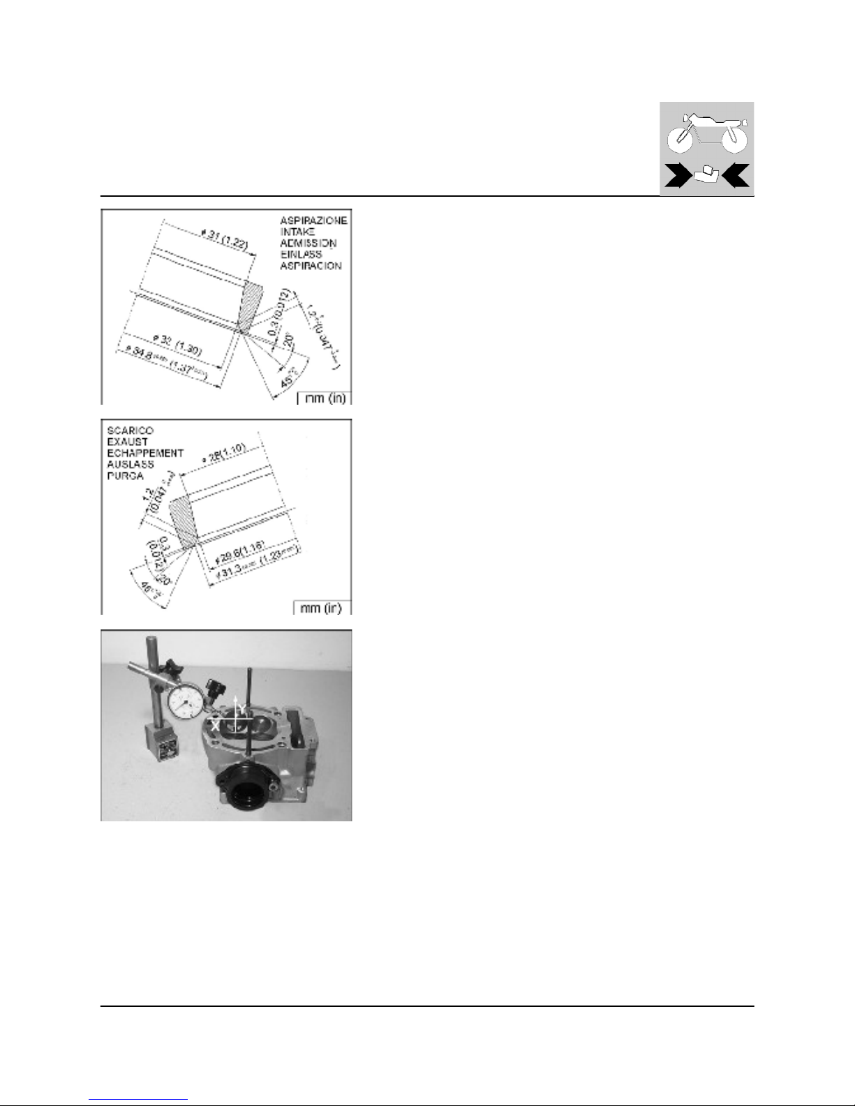
that clearances at assembly should be 0.0047÷0.0063 in for the inlet and
0.0043÷0.0062 in for the exhaust. Spare valve seats are supplied with an
oversize outer diameter of 0.0011 in. (marked in WHITE) or 0.0023
in. (marked in RED).
Evenly heat the head and keep it for 1 hour at a temperature of 200°C (392°
F).
Install the valve seats and set the valve seats with special tool.
Allow to cool then m ill the seats and grind the valves.
Valve guides
Carry out a careful visual check of the valve guides.
The valve guides should be checked for wear by measuring the clearance
between the valve stem and valve guide; use a dial gauge and measure the
clearances on the "x" and "y" axes.
Inlet valve nominal clearance: 0.000787÷0.00181 in.
Wear limit: 0.00354 in.
Exhaust valve nom inal clearance: 0.000787÷0.00181 in.
Wear limit: 0.00177 in.
http://husqy.forumsactifs.com
Page 81
7
ENGINE OVERHAULING
Replacing the valve guide
Change the valve guide as follows:
- Put the head in an oven heated at a temperature af 200 °C (392° F), and let
it there for 1 hour; drive the valve out with a drift and allow to cool; check the
condition of the valve seats.
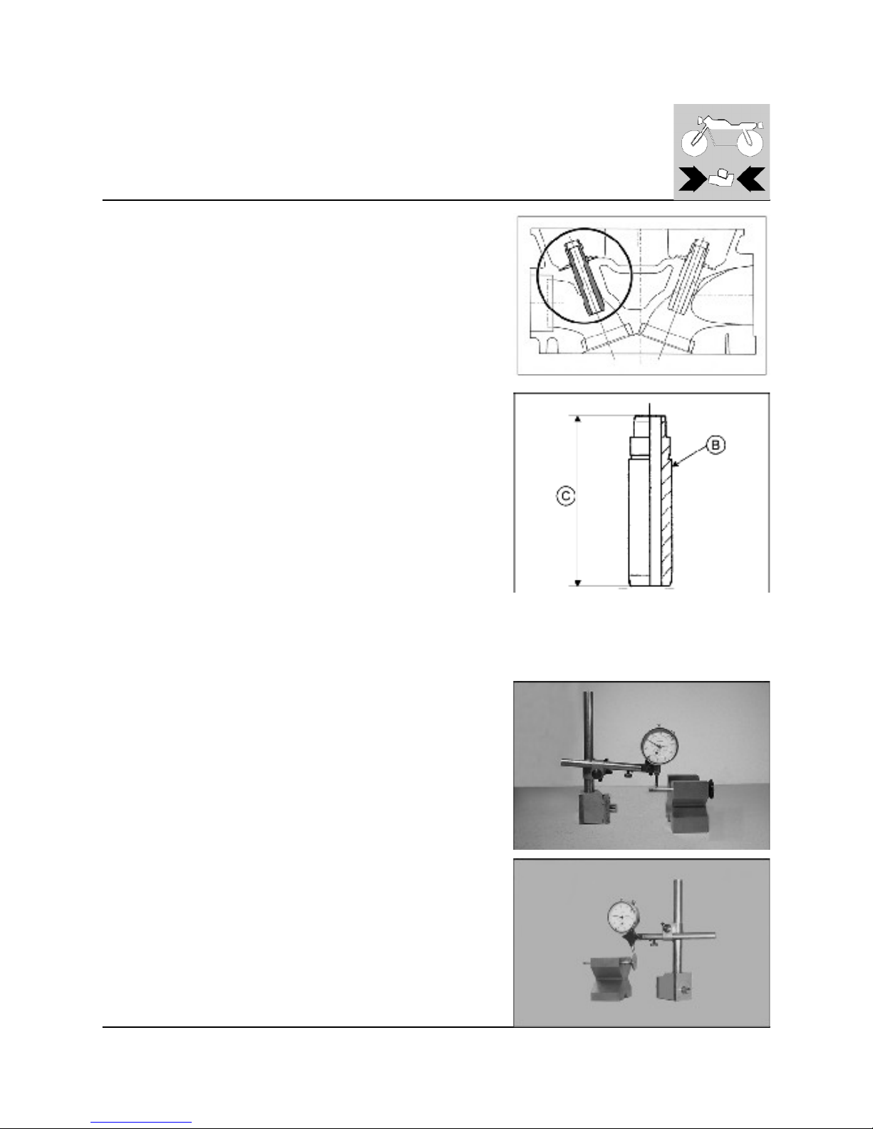
- Choose a suitable valve guide taking into account that clearances at assembly are 0.00087÷0.0020 in.: spares are supplied with an oversized external diameter (Ø 0.47 in.) of: 0.00098/0.00197 in. (these valves guides are
marked with RED and BLUE colors respectively; these distinguishing marks
are on the head);
- Reheat the cylinder head at a tem perature of 200 °C/392°F;
- Lubricate the seat with engine oil then insert the guide valve (Keep at ambient temperature: 20°C /68°F) using a suitable drift; lubricating with
MOLIKOTE G;
- Ream the internal hole (A) and lubricate;
- Fit the lower valve spring collects, lubricate and fit the new seal rings.
B: distinguishing color area
C: intake and exhaust=47 mm (1.85 in)
Valve
Check that the valve stem and contact surfaces are in good condition. There
should be no pitting, cracks, distortions or signs of wear. Carry out the follow ing checks:
- Check the valve stem for distortion by resting it on a V-block and measuring
the distortion with a comparator.
Wear limit: 0.00197 in.
- Check the concentricity of the valve head by resting an angle comparator
against the head and then rotate the valve in a V-block.
Wear limit: 0.0012 in.
http://husqy.forumsactifs.com
Page 82
8
ENGINE OVERHAULING
Valve spring
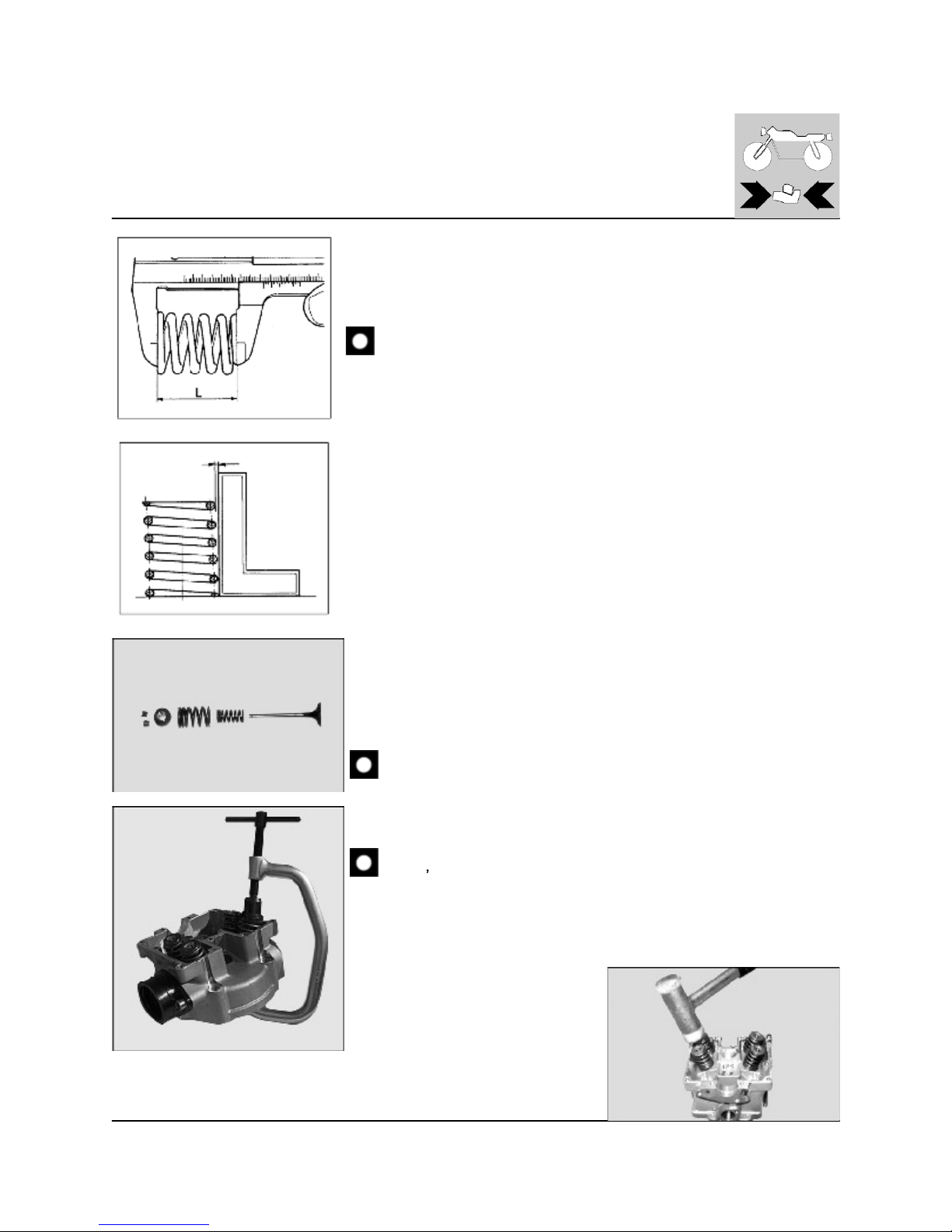
Check the free length "L". If this does not correspond to the prescribed limits then
substitute the springs.
Internal spring: L= 1.44 in. - Wear lim it: 1.34 in.
External spring: L= 1.70 in. - W ear limit: 1.65 in.
If it is necessary to change one of the springs then all the other springs
should also be changed.
Valve spring orthogonality check.
The max. obliquity is 0.06 in for side.
Installation of valves
Lubricate the valve guides and valve stem with engine oil when the valve is
installed.
Install the seal ring, the springs and the cup.
Use tool code no. 800039521 to compress the valve springs and can install halves
cones.
Do not com press the valve springs more than necessary. Do not
damage the cylinder head.
Tap gently on the valve stem with a plastic hammer to m ake the cotters seat.
Hit straight on the top of the valve stem so that the valve stem
doesn
t get out of true.
http://husqy.forumsactifs.com
Page 83
9
ENGINE OVERHAULING
Inspection of rocker arm
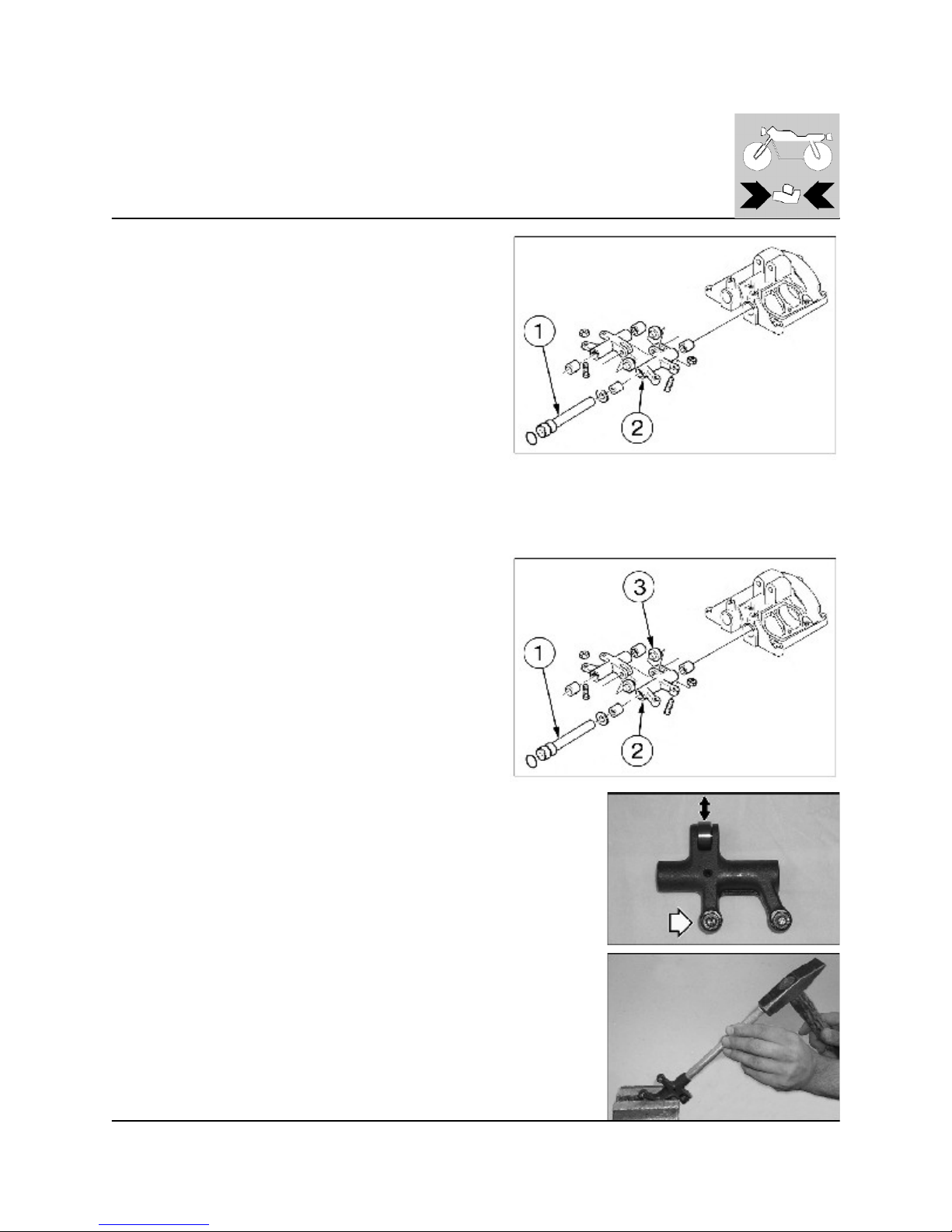
Check the clearance between the rocker arm and the rocker arm
shaft. M easure the inner diam eter of the rocker arm (2) and the
outer diameter of the rocker arm shaft (1) and accurately determine
the clearance. M aximum clearance 0.04 in.
If greater, replace the two rocker arm bushings.
Check that the pivot is not worn; in this case, replace it.
Use a 6 mm screw to push out the shafts (1) of the rocker arms (2).
Remove the rocker arm s.
Check the rocker arms for cracks.
Also check the cam rollers (3). They m ust be intact and without play
(see page G.25).
Check valve adjusters wear.
Replacement of rocker arm bushing
If the rocker arm bushings need replacem ent, remove them with a drift. Put in new
bushings using a hydraulic press or a vise with flat sides.
Ream the bushings with reamer after the installation.
http://husqy.forumsactifs.com
Page 84
10
ENGINE OVERHAULING
Cam roller replacement
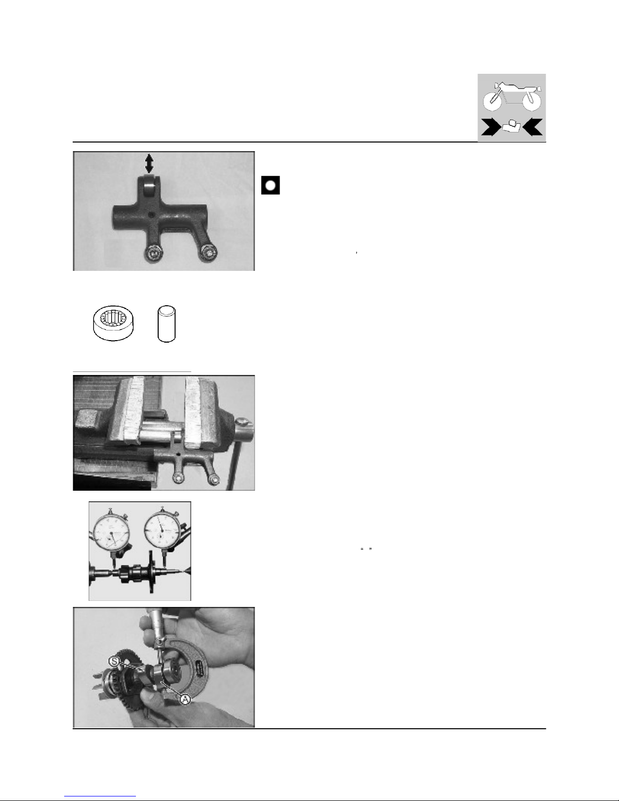
Replace the cam roller if, in consequence of the radial play im provem ent (the needle bearing pin is w orn), the valve play exceed
0.006-0.008 in., both for the intake and exhaust sides.
The pin on the new roll bearing assures the roll contact with the ring and
makes easier the pin insertion during assembly. Hold the roller with needles
in place in the rocker arm and m ount the roller shaft. Use a vise. Be careful
so that the rocker arm isn
t damaged. Lock the cam roller shaft with a center
punch from each side.
Cam shaft
Check that cam surfaces are scored, stepped, grooved etc. Excessively worn
cams are often the cause of bad engine timing thus reducing engine power.
Insert the camshaft between two references and then check deviation using
two comparators. W ear limit: 0.0039 in.
- Measure the cam height
H with a microm eter.
- H (new)= 1.315 in. for the intake; 1.307 in. for the exhaust.
- Wear lim it: 1.303 in. for the intake; 1.295 in. for the exhaust.
S: EXHAUST
A: INT AKE
http://husqy.forumsactifs.com
Page 85
11
ENGINE OVERHAULING
Tim ing chain and gears
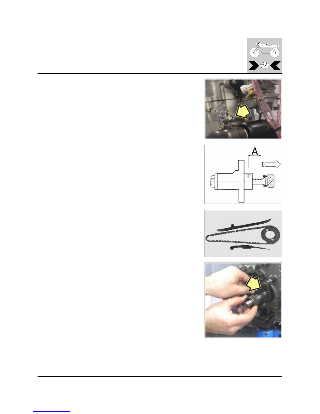
Replace the chain in presence of noisiness and if the chain tensioner on the
cylinder is at 10 clicks of its stroke (A). Check the wear of the driven gear and, even if
just one of the elements is worn out, replace all the driven gear and the chain as well.
Check also the driving gear wear (on the crankshaft, L.H. side).
Tim ing chain stretcher sliding
The cam chain tensioners should be replaced when the wear material is worn
through.
http://husqy.forumsactifs.com
Page 86
12
ENGINE OVERHAULING
Cylinder
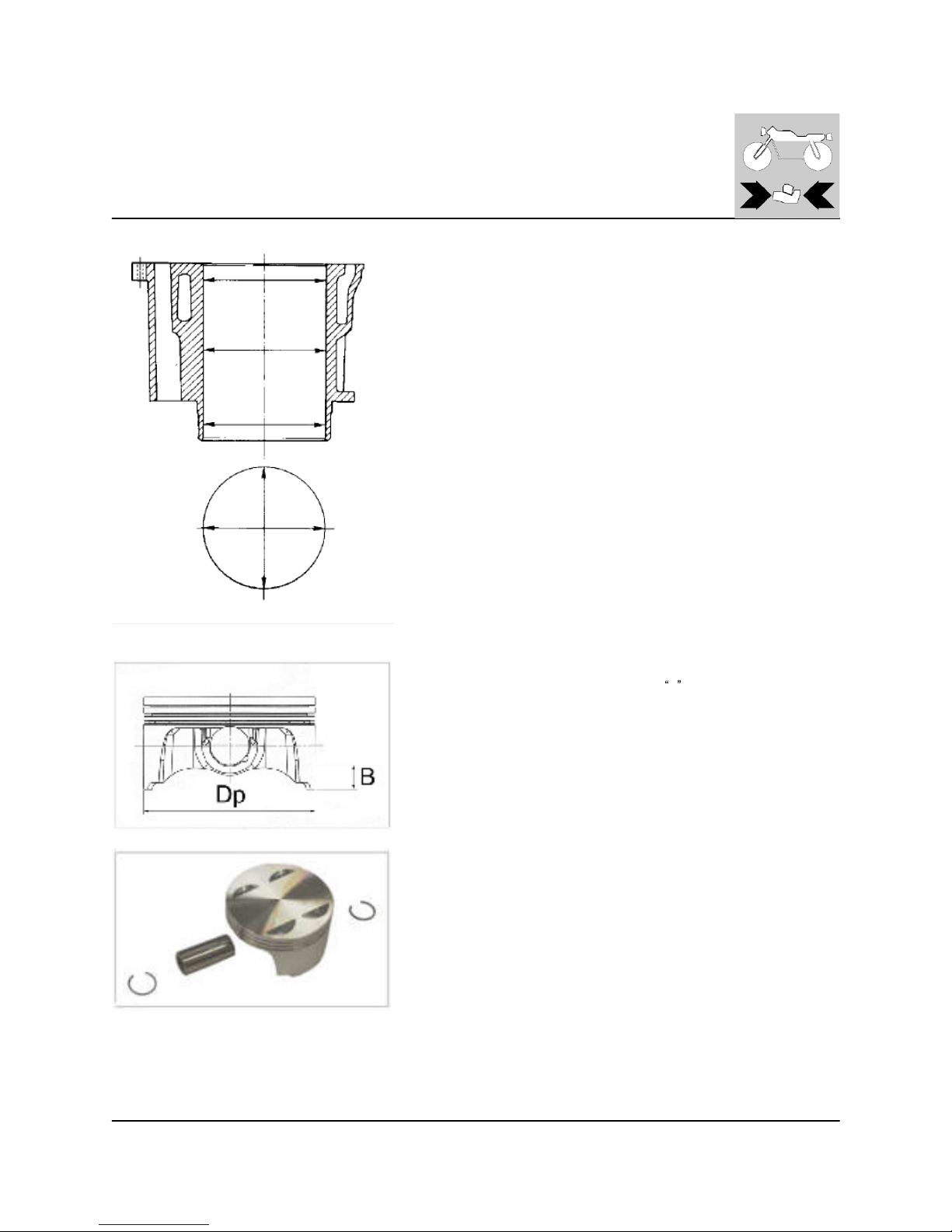
The cylinder liner bore should be completely smooth, without grooving or
scoring. To obtain the taper and the ovality of the cylinder liner bore take
measurements at three different heights and in two position at 90° to each
other.
Max taper (wear lim it):0.0019 in.
Max ovality (wear lim it): 0.0019 in.
If the wear limits are greater than those prescribed, then replace the cylinder
liner with the piston; re-boring is not possible since the cylinder liner has
been given a special hardening treatment.
Piston diam eter
Measure the piston diameter D p at a distance
B , 14 mm / 0.55 in., from the
base.
The connection play will be = Dc-Dp.
Gudgeon pin
The gudgeon pin should be perfectly smooth without scoring, grooving or
bluish discoloration caused by overheating. If it is necessary to replace the
gudgeon pin then the small end bushing should also be changed.
http://husqy.forumsactifs.com
Page 87
13
ENGINE OVERHAULING
Gudgeon pin-connecting rod small end clearance
Clearance at assem bly should be: 0.00047÷0.00106 in.
Max. admissible wear limit: 0.0022 in.
Piston rings
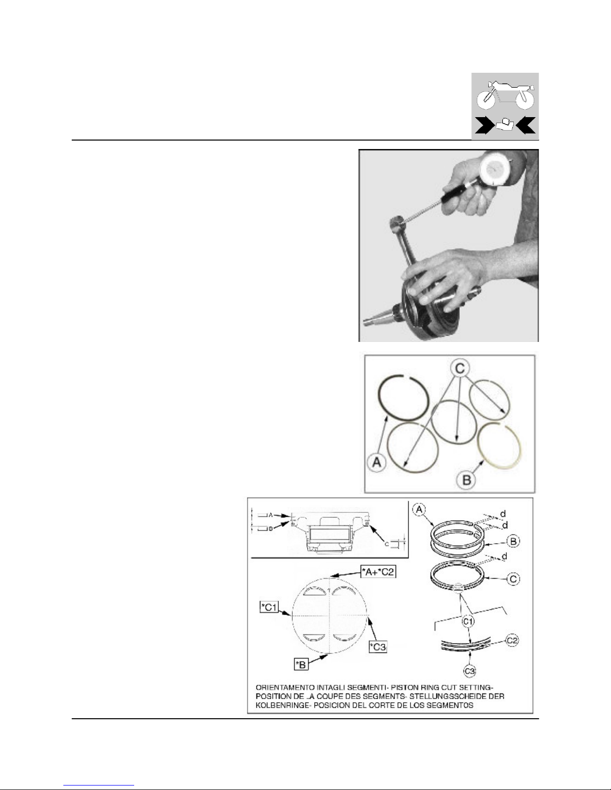
The piston rings should not show signs of excessive wear or scoring.
Spare pistons are supplied complete with rings and gudgeon pins.
Install the split rings on the piston. Set their splits as shown in the picture.
* "d" cut position
http://husqy.forumsactifs.com
Page 88
14
ENGINE OVERHAULING
Piston rings-cylinder clearance
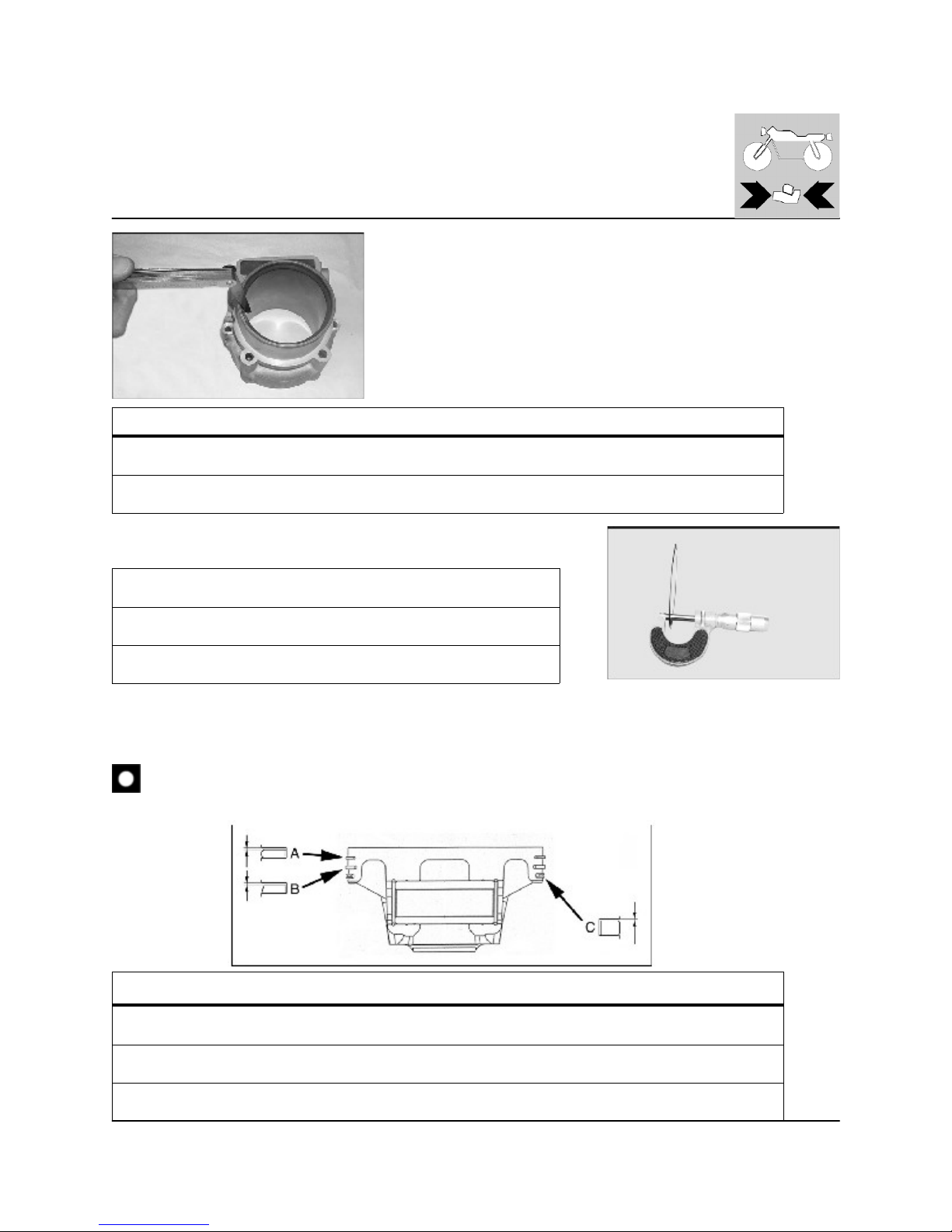
Introduce the ring into the lower part of the cylinder (i.e. where there is
least wear); ensure that the ring is squared up and then check the ring end
gap.
STANDARD W EAR LIMIT
PISTON RINGS
0,30-0,50 mm
0.0118-0.0197 in.
0,9 mm
0.035 in.
OIL SCRAPER
0,20-0,70 mm
0.0079-0.0275 in.
0,9 mm
0.035 in.
Piston rings thickness
SEGMENTO A 0,97-0,99 mm
0.0381-0.0390 in.
SEGMENTO B 1,47-1,49 mm
0.0579-0.0587 in.
SEGMENTO C 1,85 mm-2,00 mm
0.0728-0.0787 in.
Piston ring-piston rings groove clearance
Use a feeler gauge to check the axial play of the rings in the groove.
On 1st and 2nd piston ring the m ark m ust be turned
highw ards.
STANDARD W EAR LIMIT
SEGMENTO A 0,02-0,06 mm
0.00079-0.00236 in.
0,2 mm
0.0079 in.
SEGMENTO B 0,02-0,06 mm
0.00079-0.00236 in.
0,2 mm
0.0079 in.
SEGMENTO C 0,01-0,18 mm
0.0004-0.0071 in.
0,4 mm
0.0157 in.
http://husqy.forumsactifs.com
Page 89
15
ENGINE OVERHAULING
Connecting rod big end radial clearance
STANDARD W EAR LIM IT
0,26-0,36 mm
0.00102-0.00141 in.
0,080 m m
0.00315 in.
Connecting rod big end axial clearance
STANDARD W EAR LIM IT
0,50-0,70 mm
0.0197-0.0275 in.
0,080 m m
0.00315 in.
Balance counterlec
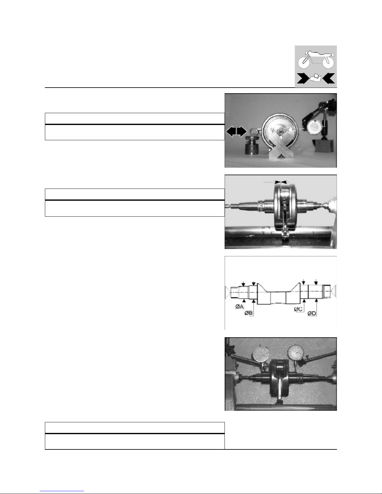
Use a comparator to check the alignment of the pins by positioning the
counter shaft between two points (max. error: 0.0008 in.).
Wear limit ØA=0.667 in.
Wear limit ØB=0.786 in.
Wear limit ØC=0,786 in.
Wear limit ØD=0.7858 in.
Crankshaft
Conrod journals and main journals be free indentations or scoring; threading,
key housing and grooves m ust be in good conditions.
With the aid of a com parator measure the alignment of the conrod journals
placing the crankshaft between two centers (max. admitted error 0.0008 in.).
Crankshaft run-out
STANDARD W EAR LIM IT
under 0.00078 in.
0,050 m m
0.0019 in.
http://husqy.forumsactifs.com
Page 90
16
ENGINE OVERHAULING
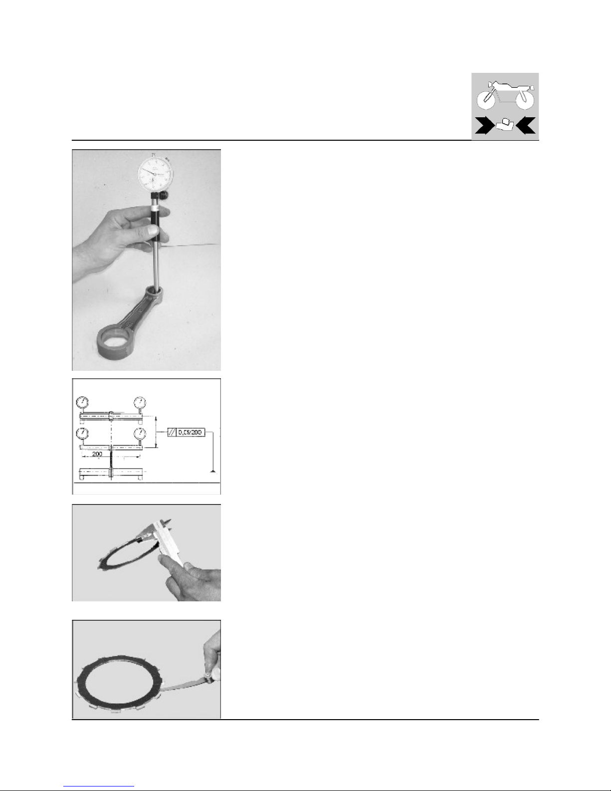
Replacing the small end bush
The bush should be replaced using a correct size punch and drift.
Before the reassembly apply on the bush MOLYBDENUM BISULPHIDE GREASE.
The clearance between the bush and its seat is: 0.00193÷0.00374 in.
The lubrication holes on the new bush should correspond with those on the
connecting rod; ream the bush to an internal diameter of 0.945÷0.946 in.
Check the parallelism.
Clutch unit
Check that all clutch unit components are in good condition. The clutch plates
should be not burnt or scores. Check the thickness of the clutch lining plate.
Thickness of new plate: 0.115÷0.121 in.
Wear limit: 0.104 in.
Check the distortion of each plate (both lines and unlined) by resting on a flat
surface; use a feeler gauge.
Wear limit: 0.0078 in.
http://husqy.forumsactifs.com
Page 91
17
ENGINE OVERHAULING
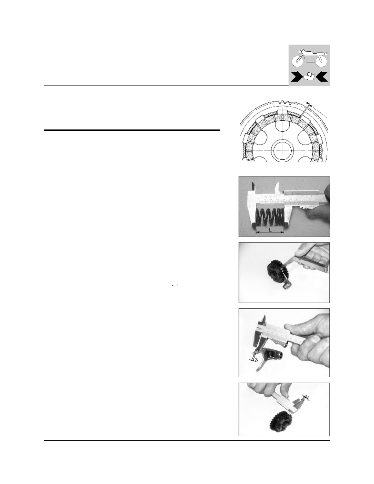
Clutch housing-friction disc clearance
STANDARD W EAR LIM IT
0,55-0,75 mm
0.022-0.029 in.
0,09 mm
0.0035 in.
Clutch spring
Check the free length "L" of each spring with a gauge.
New spring: L= 1.61in. W ear lim it: 1.53 in.
Replace any spring which does not m eet with this specification.
Gear selector fork and gearing
Carry out a visual inspection of the gear selector forks; any bent forks should be
replaced. A bent fork will make gear changing difficult and can cause the gear to
disengage without notice under power.
Use a feeler gauge to check the clearance between each selector fork and the
groove on its gear. If the prescribed wear limit is exceeded for any one of the three
gears then it is necessary to establish whether the gear or the selector fork it so
be changed; this can be done by m easuring the thickness
S and the width 2L2
of the gear groove.
Clearance between fork and rear (new): 0.00275 ÷ 0.00885 in.
Wear limit: 0.01 in.
http://husqy.forumsactifs.com
Page 92
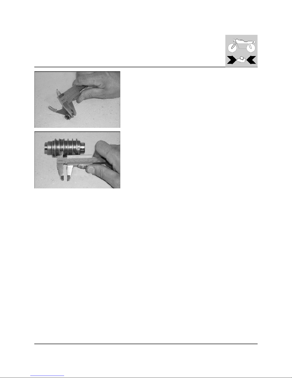
18
ENGINE OVERHAULING
Fork control drum - fork pins coupling
Check the clearance between the selector pin and the selector drum groove
by m easuring the two clearances with a gauge. If the wear limit is exceeded
then establish which part is be replaced by comparing values with new parts.
Clearance between selector pin and drum grooving, with new components:
0.006÷0.0138 in.
Wear limit: 0.029 in.
http://husqy.forumsactifs.com
Page 93
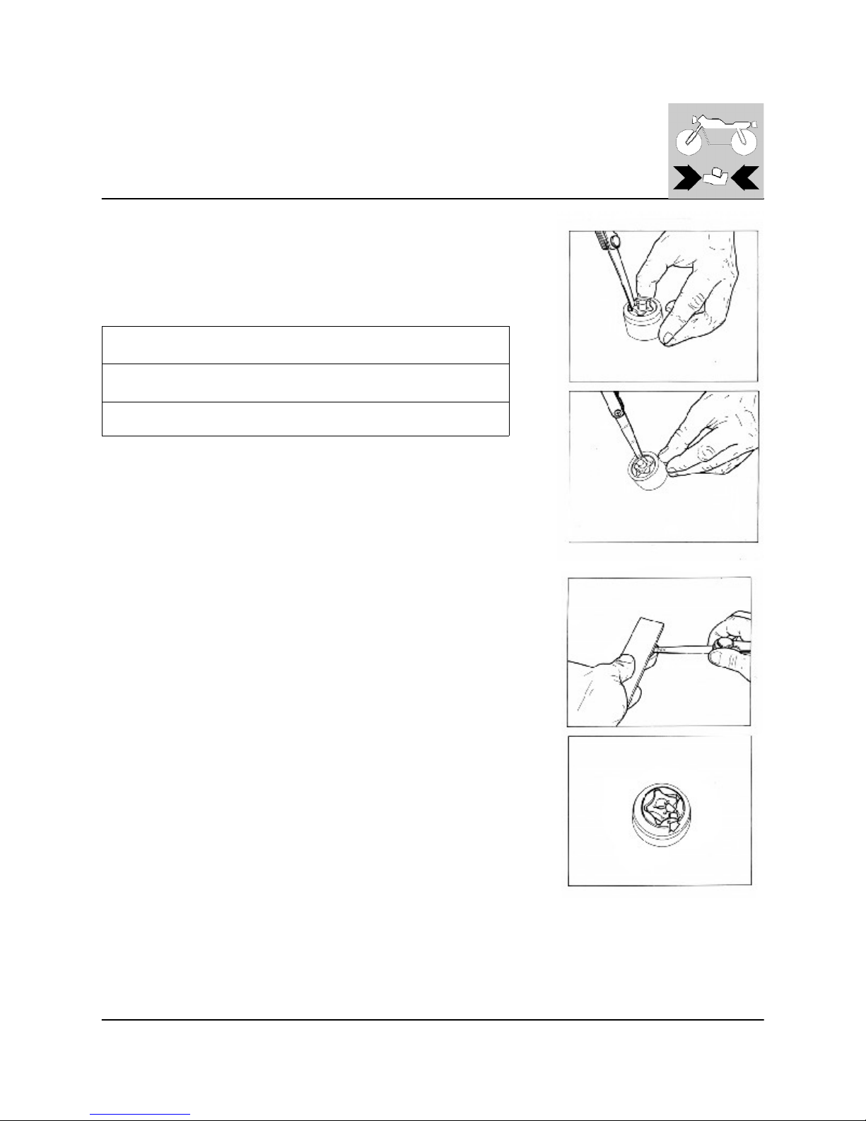
19
ENGINE OVERHAULING
Oil pum p
There are three clearances which have to be checked to establish whether the oil
pump needs changing or not; use a straight edge and a feeler gauge.
If the oil pump rotors have been dismantled then check, at reassembly, that the marks
on the internal rotor and the mark on the external rotor are aligned. Check that the
pump m ounting surface is not scored, grooved or pitted.
Clearance between external and
internal rotor
0,20 mm
0.0078 in.
External clearance between rotor
and pump body
0,25 mm
0.0098 in.
Side play
0,10 mm
0.0039 in.
http://husqy.forumsactifs.com
Page 94
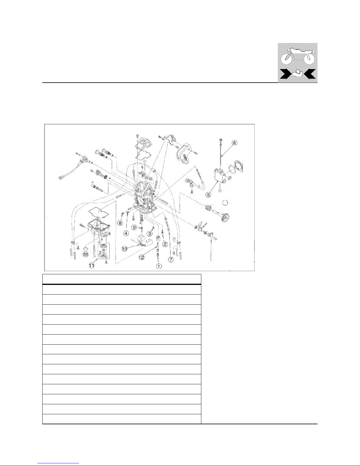
20
ENGINE OVERHAULING
"KEIHIN" carburetor overhauling
Thoroughly wash with petrol and dry with compressed air all carburetor componets. Thoroughly clean all jets and ducts with
compressed air only.
Never use tips of metal wires. Check that the gate valve is in good condition and runs freely in its housing but without excessive
clearance.
Check that the pin and spray nozzle are in good conditions. Check that the pin valve has a good seal.
CARB URETTOR SETTING "KEIHIN" FCR-M X 41
1
Main jet 172
2
Idle jet 50
3
Starting jet 85
4
Main air jet 200
5
Throttle valve 15/M
6
Tapered needle/needle position OBDVR/4th
7
Air screw, open by turns 1+1/2
8
Low air jet 100
9
Needle valve
10
Floater g 11,2
11
Accelerator pum p
12
Needle jet
-
Starting air jet 0.16 in.
-
Venturi diam eter 1.61 in.
http://husqy.forumsactifs.com
Page 95
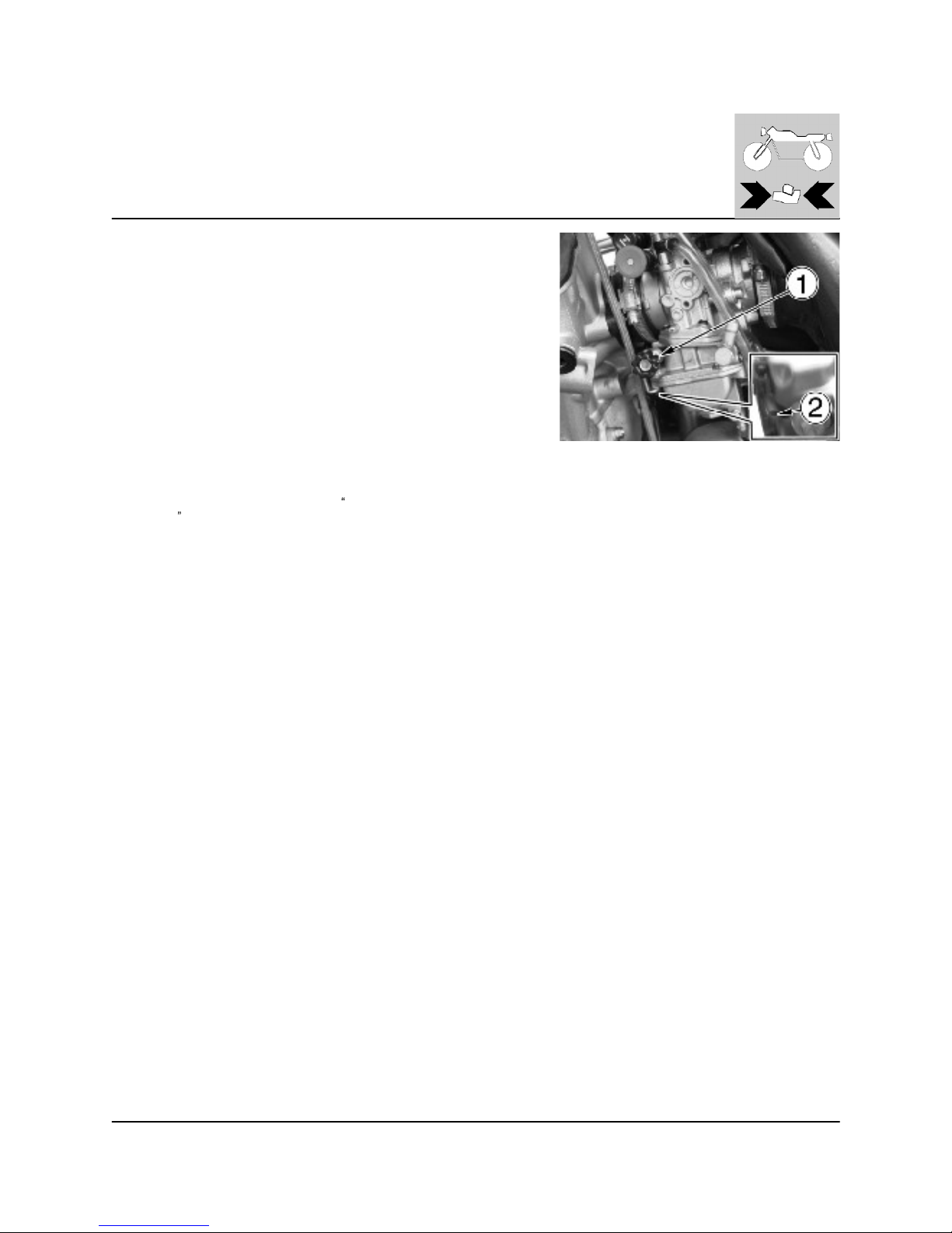
21
ENGINE OVERHAULING
Carburetor adjustment
Adjust the carburetor with warm engine and with the throttle in closed position.
Work as follows:
- Turn slow running adjusting screw (1) on the left side of the bike until the
engine is turning over at fairly high rpm (turn the screw clockwise to increase
the rpm, and anticlockwise to decrease the rpm ).
- Turn adjusting screw (2) clockwise until the fully closed position is reached
then turn back 1,5 turns.
- progressively loosen adjusting screw (1) to obtain the slow running required.
NOTE
An incorrect idle jet size could cause troubles of starting of the engine.
In this case:
- if turning the screw (2), no engine speed change is obtained, a sm aller idle
jet has to be installed;
- if the engine stops when the screw (2) is not yet completely turned, a larger
idle jet has to be installed.
After the idle jet replacem ent, repeat the
Carburetor
adjustment
.
Besides, if with a completely throttle grip open, poor acceleration or slow
pickup of the engine or sooty spark plug are obtained, it is necessary to
check the wear of these carburetor parts: throttle valve, m etering pin and
needle jet (mixture enrichment). See the next pages.
Idle adjustment
Adjust the carburetor with warm engine and with the throttle control in closed
position.
Proceed as follows:
- Turn slow running adjusting screw (1) on the left side of the bike, near the
fuel cock (turn the screw clockwise to increase the rpm, and anticlockwise to
decrease the rpm).
Carburetor checking
1. Inspect:
- Carburetor body
Contamination: Clean
2. Inspect:
- Main jet (1)
- Pilot jet (2)
- Needle jet (12)
- Pilot screw (7)
- Starter jet (3)
- Main air jet (4)
- Pilot air jet (8)
Damage: Replace
Contamination: Clean
NOTE:
- Use a petroleum based solvent for cleaning. Blow out all passages and jets
with compressed air.
- Never use a wire.
http://husqy.forumsactifs.com
Page 96
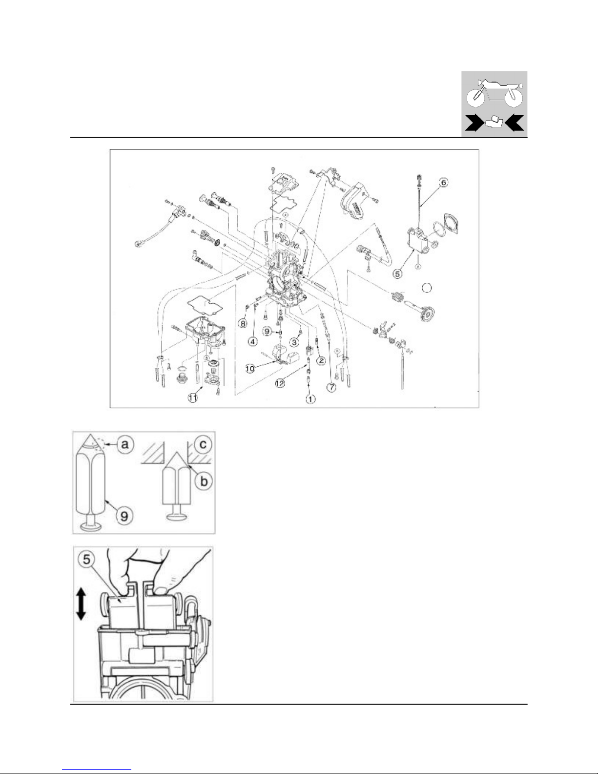
22
ENGINE OVERHAULING
NEE DLE V ALVE
Inspect needle valve (9) and valve seat (c)
Grooved wear (a): Replace. Dust (b): Clean.
THR OTTLE VALVE
Check for free movem ent.
Stick: Repair or replace.
Insert the throttle valve (5) into the carburetor body, and check for free movement.
http://husqy.forumsactifs.com
Page 97
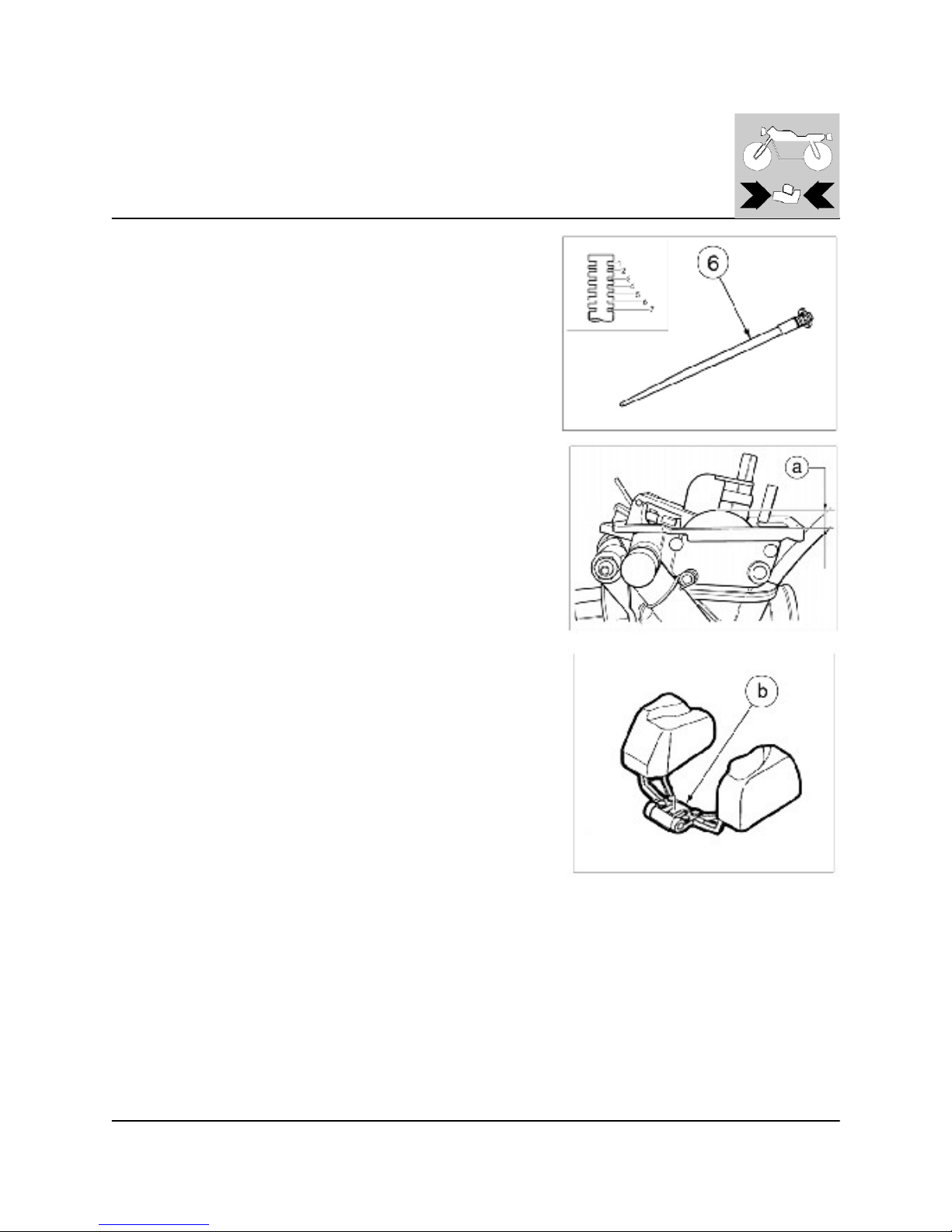
23
ENGINE OVERHAULING
JET NEEDLE
Inspect jet needle (6).
Bends/W ear: Replace.
Standard clip position: 4th Groove.
FLO ATH EIGHT
Measure:
- Float height (a).
Out of specification: Adjust.
Float height: 8 m m (0.31 in.)
Measurement and adjustm ent steps:
- Hold the carburetor in an upside down position.
NOTE:
- Slowly tilt the carburetor in the opposite direction, then take the measurement when the needle valve aligns with the float arm .
- If the carburetor is level, the weight of the float will push in the needle valve,
resulting in an incorrect measurement.
- Measure the distance between the mating surface of the float chamber and
top of the float using a vernier calipers.
NOTE:
The float arm should be resting on the needle valve, but not compressing the
Needle valve.
- If the float height is not within specification, inspect the valve seat and needle valve.
- If either is worn, replace them both.
- If both are fine, adjust the float height by bending the float tab (b) on the
float.
- Recheck the float height.
http://husqy.forumsactifs.com
Page 98
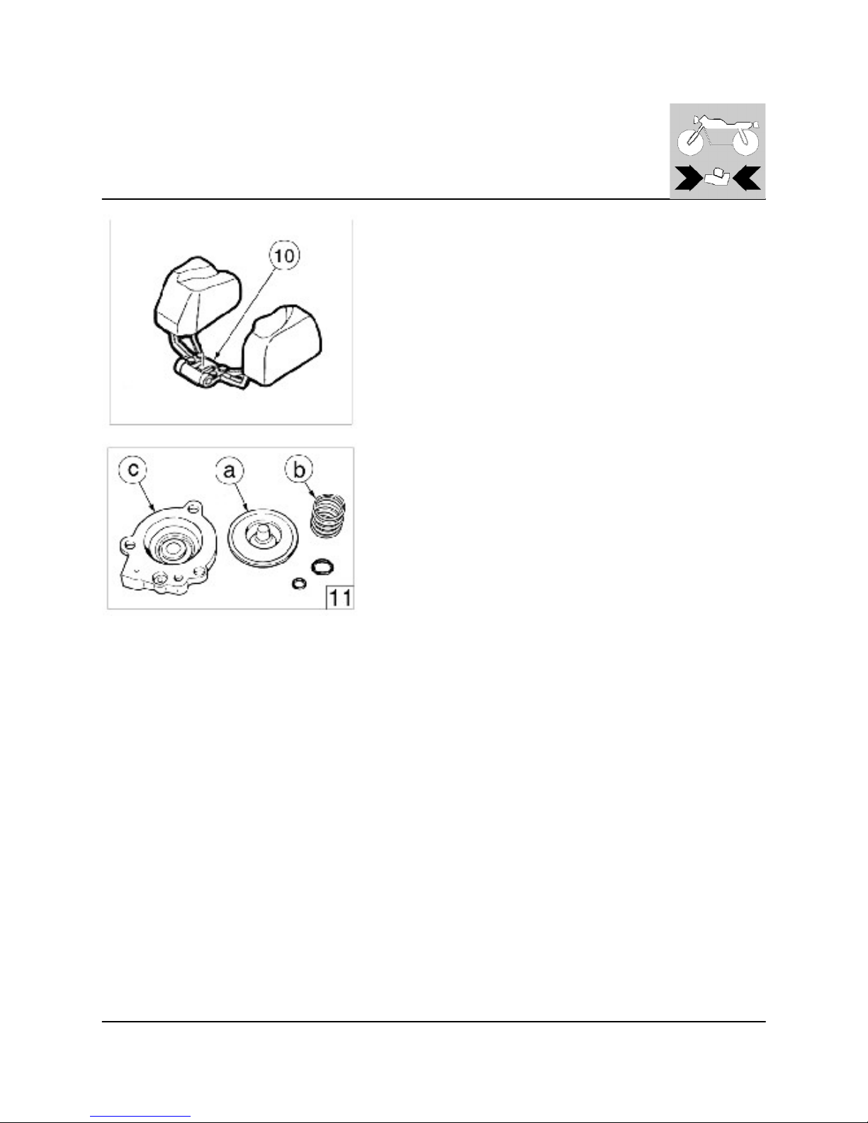
24
ENGINE OVERHAULING
FLO ATE R
Inspect:
- Float (10).
Damage: Replace.
ACC ELERATO R PUMP
Inspect:
- Diaphragm (accelerator pum p 11) (a).
- Spring (b).
- Cover (c).
Tears (diaphragm ) / Damage ® Replace.
http://husqy.forumsactifs.com
Page 99
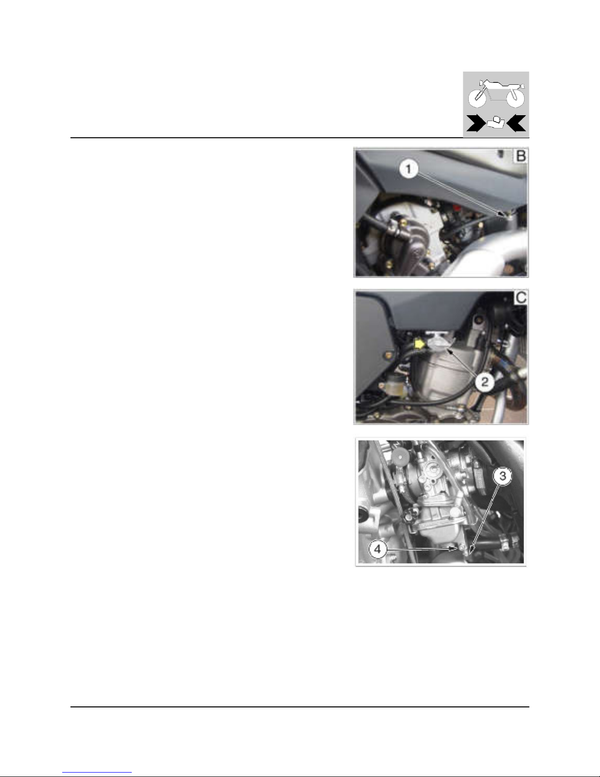
25
ENGINE OVERHAULING
Fuel draining
To drain the fuel from the carburetor float cham ber, close the L.H. side fuel
cock (1, fig. B) and place the R.H. fuel cock (2, fig. C) on OFF position. Place
the hose (3) in a vessel, loosen the drain screw (4) on the float chamber
lower side, then tighten the screw again after the fuel drain.
WARN IN G
Never litter the environment with fuel, and let the engine running in open air,
never in closed room s.
http://husqy.forumsactifs.com
Page 100

26
http://husqy.forumsactifs.com
 Loading...