

Page 1

67 – German
Workshop manual
English
R135, R333, RJ333, RJ535, RJX335, RX335, RX535,
RXT535, FR335, FR336, FRD336, LS335, LS535, LX335
Page 2

1
1
Starter
© Copyright Husqvarna AB, Sweden 2012
Workshop Manual
Brushcutter, Trimmer
Models
R RJ RJX RX RXT FR FRD LS LX
135 333 335 335 535 335 336 335 335
333 535 535 336 535
Contents
General recommendations ___________________________2
1. Starter _________________________________________3
2. Electrical system _________________________________9
3. Fuel system ___________________________________ 17
4. Centrifugal clutch ______________________________ 36
5. Angle gear ____________________________________ 41
6. Cylinder and piston _____________________________ 45
7. Crankshaft and crankcase ________________________ 55
8. Tools ________________________________________ 61
9. Technical Data _________________________________ 65
Page 3

2
1
Starter
General recommendations
Bear in mind:
Do not start the machine without making sure the cut-
ting attachment and all the safety features are tted
and working properly.
To avoid burns, do not touch hot components, e.g. the
mu er before they have cooled su ciently.
Avoid getting fuel or oil on your skin or in your mouth.
Use a barrier cream on your hands. This reduces the
risk of infection and makes dirt easier to wash away.
Long term contact with engine oil can represent a
health hazard.
Never start the engine indoors. Exhaust fumes are
poisonous! They contain carbon monoxide, an odourless, poisonous and highly dangerous gas.
Wipe up oil spills from the oor immediately to avoid
slipping.
Do not use tools that are worn or t badly, for example
on nuts and bolts.
+ Always work on a clean bench.
+ Always work logically to ensure all parts are tted cor-
rectly and that nuts and bolts are tightened.
+ Use the special tools where recommended to be able
to carry out the work correctly and e ciently.
Fire risk
Handle fuel with respect as it is extremely in ammable.
Never refuel while the engine is running.
Do not smoke and ensure there are no open ames or sparks
in the vicinity.
Never start the engine if the machine is leaking fuel or if there
has been a spillage when refuelling. Allow the remaining fuel
to evaporate rst.
Make sure there is a working re extinguisher close at hand.
Do not try to extinguish a petrol re with water.
Poisonous fumes
When using cleaning agents read the instructions carefully.
Ensure there is good ventilation when handling petrol and
other volatile uids.
The engine’s exhaust fumes are poisonous. Test run the
engine outdoors.
Special tools
Some of the work described in this workshop manual requires special tools. In each section where this is necessary
there is a picture of the tool and an order number.
We recommend the use of special tools in order to avoid expensive damage to parts in question and personal injury and
to provide an e cient repair procedure.
Contact faces and gaskets
Ensure all surfaces are clean and free from gasket residue,
etc. When cleaning use a tool that will not damage the contact face. Any scratches or unevenness should be removed
using a at ne cut le.
Sealing rings
Always replace a sealing ring that has been dismantled.
The sensitive sealing lip can easily be damaged resulting in
inferior sealing capacity. Surfaces which the seal shall seal
against must also be completely undamaged. Lubricate the
sealing lip with grease before it is tted and ensure that it is
not damaged e.g. by shoulders and splines on a shaft. Use
tape or a conical sleeve as protection. It is important that
the sealing ring faces in the right direction for it to act as it is
intended.
The workshop used to carry out repairs must be equipped
with safety devices in accordance with local directives.
No one may carry out repairs without rst having read and
understood the contents of this Workshop Manual.
The boxes below can be found in appropriate parts of this
manual.
WARNING!
The warning box warns of the risk for
personal injury if the instructions are not
followed.
NOTE!
This box warns of damage to material if the instructions are not followed.
The machine is type approved for safety in accordance with
applicable legislative demands with the equipment speci ed
in the Operator’s Manual. The assembly of other equipment
or accessories or spare parts not approved by Husqvarna can
result in the failure to meet these safety demands and that
the person carrying out assembly bears responsibility for this.
Page 4

3
1
Starter
1
Starter
Contents
Dismantling _______________________________________ 4
Assembly__________________________________________ 5
Assembling the starter with a start assistance spring ______ 5
Replacing the drive dogs _____________________________ 7
Page 5

4
1
Starter
502 50 18-01
502 50 18-01
502 50 18-01
!
WARNING!
Wear protective glasses.
The return spring lies tensioned
in the starter and can y out
and cause personal injury with
careless handling.
WARNING!
Protective glasses should be worn when working on the starter to avoid injury to the
eyes if, for some reason, the return spring should y out.
!
Dismantling
Model 336
Remove 2 of the screws holding the
cover under the engine against the
starter.
Loosen the 3 screws that hold the
starter in place and remove the starter.
The cylinder cover does not need to be
loosened or detached.
Dismantling
Model 333/335
Remove the 4 screws and carefully
swing down the protective plate so far
that the starter can be lifted out.
The cylinder cover does not need to be
loosened or detached.
NOTE!
Ensure the bushings that guide the starter towards the fuel tank are not lost.
The starter equipped with a start assistance spring is dismantled in the same way
as described above. However, to remove the screw in the centre of the starter pulley
requires a 5 mm Allen key, e.g. 502 50 64-01.
Remove the bolt in the centre of the
starter pulley and remove the starter
pulley.
Remove the bolt in the centre of the
starter pulley. Lift the starter pulley carefully from the starter cover.
Loosen the spring tension. Loosen the spring tension.
Pull out the starter cord about 30 cm.
Brake the starter pulley with your thumb
and lift the cord as illustrated.
Let the starter pulley rotate backwards
slowly.
Page 6

5
1
Starter
Assembly
Clean the component parts and assemble in the reverse order as set out for
dismantling.
Assembly
Clean component parts before
assembling.
Replace the return spring/starter pulley
and starter cord, if necessary.
Lubricate the spindle with a little grease
and t the starter pulley.
Position the washer and tighten the
screw.
NOTE!
The return spring and starter pulley
are supplied pre-assembled and
are tted in the starter housing as a
single unit.
Exercise care when opening the
packaging so that the spring does
not y out.
Assemble the starter pulley.
Assemble a new starter cord.
NOTE!
A new starter cord can be tted
without the need of dismantling
the starter!
Assemble a new starter cord.
Assemble a new starter cord. Slide it
into the slot on the starter pulley as
shown in the picture.
Make sure that the knot at the end of the
cord is as small as possible and that it is
pressed in the starter pulley!
Assembling the starter
with a start assistance
spring
Clean the component parts and assemble in the reverse order as set out for
dismantling.
Assembling the starter
with a start assistance
spring
Clean component parts before
assembling.
Replace the return spring/starter pulley
and starter cord, if necessary.
NOTE!
The return spring and starter pulley
are supplied pre-assembled and
are tted in the starter housing as a
single unit.
Exercise care when opening the
packaging so that the spring does
not y out.
Page 7

6
1
Starter
A
B
C
D
E
502 50 64-01
Assemble the starter handle.
Tie a double knot on the starter cord and
fold under the free end.
Pull the knot fully into the handle.
Lubricate the spindle with a little grease
and t the starter pulley.
Move the starter cord through the guide
in the starter housing.
Assemble the starter pulley.
Place the start assistance spring (A) in
position.
Position the cover disc (B) over the start
assistance spring and make sure that
the spring pin enters the disc correctly.
Place the spacer (C) and washer (D) in
position in the hub on the cover disc (B).
Tighten the screw (E) in the centre of
the starter pulley.
Position the start assistance spring in
position in the starter pulley and assemble the other parts as in the illustration.
Tighten the screw in the centre of the
starter pulley.
Page 8

7
1
Starter
502 51 49-01
Fit the starter on the engine body.
1. Check that the rubber bushings (A)
are in position in the starter housing.
2. Insert the small tab (B) on the
periphery of the starter under the
carburettor cover and swing the
starter in against the engine body.
3. Press the starter in against the
engine body.
4. Pull the starter handle and check
that the drive dogs engage.
5. Screw on the starter and the protective plate.
Tension the return spring.
Check the spring tension.
Tension the return spring.
Pull out the starter cord completely and
slow the starter pulley with your thumb.
Lift the starter cord up out of the cut-out
on the starter pulley.
Now turn the starter pulley anticlockwise, 6 turns.
For starters with a start assistance
spring, the starter pulley must be turned
anti-clockwise 5 turns.
Check the spring tension. With the starter cord fully extended it should still be
possible to turn the starter pulley further,
at least a half turn.
Remove the circlip and replace any damaged drive dogs or springs, if necessary.
Remove the circlip holdings the drive
dog.
Lift out the drive dog and spring for
replacement.
Assemble in the reverse order as set
out for dismantling.
Check that the drive dogs move easily!
Replacing the drive
dogs
Dismantle the drive body.
Replacing the drive
dogs
Fit the puller 502 51 49-01 on the ywheel (see chapter 2 ”Electrical system”) and loosen the drive cup.
NOTE!
The nut is brazed onto the drive
cup.
Do not use, e.g. a pair of slip-joint
pliers to hold the drive cup. It can
easily be deformed so that the
drive dogs cannot move freely.
Page 9

8
1
Starter
Page 10

9
2
Electrical system
2
Electrical system
Contents
Checking the ignition spark ______________________ 10
Dismantling __________________________________ 12
Assembly_____________________________________ 14
Page 11

10
2
Electrical system
502 51 91-01
502 71 13-01
333/335
336
The engine is equipped with an electronic ignition system completely without moving parts. Consequently, a
faulty component cannot be repaired, but must be replaced by a new component.
The spark in an electronic ignition system has a very short burn time and can therefore be interpreted as
weak and can be di cult to see while troubleshooting.
Make sure the stop switch is in the start
position (333/335).
Earth the spark plug on the cylinder
(333/335) or earth it using a steel wire
around a starter screw that is screwed
to the crankcase (336).
Give a sharp pull on the starter handle.
A spark should be seen between the
electrodes.
If no spark is seen test with test spark
plug no. 502 71 13-01.
If a spark then occurs, the spark plug is
faulty.
Try a new spark plug.
Checking the ignition
spark
Clean the electrodes and check the
electrode gap.
Checking the ignition
spark
Remove the spark plug and clean it from
soot deposits with the help of a steel
brush.
Check the electrode gap. It should be
0.5 mm.
Adjust the gap as needed to the correct
value with the side electrode.
If the electrodes are worn more than
50% the spark plug should be changed.
If the electrodes are worn more than
50% the spark plug should be changed.
Too large a spark gap entails a great
deal of stress on the ignition module and
risk for short-circuiting.
Page 12

11
2
Electrical system
502 50 06-01
When there is still no ignition spark,
dismantle the short-circuit cable from the
stop switch.
Remove the connector by prying it up
out of the throttle with a knife.
Still no spark?
Check the short-circuit cable with the
help of an Ohmmeter.
Also see ”Dismantling” below.
Still no spark?
Check the ignition cable’s connection to
the spark plug cover.
Still no spark?
Check the spark plug connection.
Remove the spark plug cover and make
sure the ignition cable is not damaged.
Remove a segment of cable if required
to get su cient contact at the connection coil.
Use pliers no. 502 50 06-01 to make a
hole in the ignition lead.
When a part of the ignition lead has
been cut o it helps to use the pliers no.
502 50 06-01 to make a hole in the ignition lead to t the contact coil.
NOTE!
It is important that the tip of the
contact coil hits the centre of the
ignition lead to prevent sparking.
Attach the ignition coil to the ignition
cable.
Attach the ignition coil to the ignition
cable and ensure that the wire is folded
along the cable.
Slide the contact coil into the spark plug
cover.
TIP!
Lubricate the hole in the spark plug
cover so that it is easier to slide in the
contact coil.
Page 13

12
2
Electrical system
502 51 34-02
0.3
336
333/335
Dismantling
The following components must be
dismantled for the ignition system to be
accessible:
The air lter cover, the spark plug, the
shield under the engine, the starter, the
cylinder cover and the cover over the
mu er.
Unhook the throttle cable from the
carburettor.
NOTE!
Do not lose the rubber bushings
tted between the starter and the
fuel tank.
Still no spark?
Check the air gap.
See ”Dismantling” below.
Still no spark?
Check the air gap between the ywheel
magnet and the ignition module. The
gap should be 0.3 mm.
Use a 502 51 34-02 feeler gauge.
See ”Dismantling” below.
Still no spark?
Check other cables and connections.
Still no spark?
Check other cables and connections
for poor contacts (dirt, corrosion, cable
breakage and damaged insulation).
Make sure that the cables are correctly
drawn and lie in the cable grooves.
Do not forget to check the cables in the
throttle too.
See chapter 3 “Throttle”.
TIP!
Use an Ohmmeter in order to easily
check if cable breakage has occurred,
due to pinching, for example.
Adjust the air gap.
Adjust the air gap as needed to the correct value.
• Loosen the bolts.
• Position the feeler gauge and press
the ignition module against the ywheel.
• Tighten the bolts and check the air
gap again.
If the spark plug still does not re, the
ignition system should be replaced.
Page 14

13
2
Electrical system
F
G
E
E
E
336333/335
Remove the 3 screws (E) and swing the
engine body to one side.
Remove the 3 screws (E) and swing the
engine body to one side.
Dismantle the short-circuit cable from
the ignition module.
Dismantle the short-circuit cable from
the ignition module by removing the
screw (F) and prying o the at pin connector (G).
Option B
Lift out the ignition lead and short-circuit
cables from their guides.
Remove the 3 screws (E) and swing the
engine body to one side so the clutch
becomes accessible.
Option A
Loosen the screw and slide the cable
holder (B) forwards.
Remove the screws and slide the cover
(D) forwards.
Option A
Loosen the screw (A) and slide the cable holder (B) forwards on the shaft.
Remove the screws (C) and slide the
cover (D) forwards on the shaft.
Page 15

14
2
Electrical system
502 51 49-01
502 51 49-01
502 50 18-01
Remove the nut holding the ywheel. Remove the nut holding the ywheel.
Fit the puller on the ywheel. Loosen
and remove the nut.
NOTE!
The completely at side on the
clutch should rest against the
washer closest to the ywheel.
Remove the ywheel. Dismantle the ywheel from the crank-
case using the puller
no. 502 51 49-01.
Gently knock the puller screw with a
hammer, if the ywheel sits tightly on the
crankshaft.
Assembly
Check that the cast key in the ywheel
and key way in the crankshaft are undamaged.
Fit the ywheel and centrifugal clutch.
Do not forget the washers (A).
Note the slots on the washer lie closest
to the ywheel. Align with the equivalent
pins on the ywheel.
Dismantle the ignition module and the
centrifugal clutch.
Remove the remaining screws (A)
holding the ignition module and both
screws (B) that hold the centrifugal
clutch.
Lift o the clutch, both support washers
and the ignition module.
Page 16

15
2
Electrical system
502 51 34-02
0.3
Assemble the ignition module.
Adjust the air gap. It should be 0.3 mm
between the permanent magnets in the
ywheel and the ignition module.
Tighten the screws and do not forget
the ring cable lug under the outer screw.
Assemble other parts in the reverse
order as set out for dismantling.
NOTE!
Do not forget the rubber bushings between the fuel tank and the crankcase/
clutch cover and the fuel tank and starter.
Assemble the ignition module and adjust the air gap to 0.3 mm.
Page 17

16
2
Electrical system
Page 18

17
3
Fuel system
3
Contents
Air lter ________________________________________ 18
Tank venting ____________________________________ 19
Fuel lter _______________________________________ 19
Fuel pump ______________________________________ 20
Carburettor _____________________________________ 20
Throttle ________________________________________ 29
Start throttle speed ______________________________ 31
Carburettor settings ______________________________ 32
Fuel system
Page 19

18
3
Fuel system
505 69 85-70
531 00 60-76
336
336333/335
333/335 336
In addition to the fuel tank and carburettor, the fuel system consists of the air lter, fuel lter and tank venting.
All these components interact so that the engine receives the optimal mixture of fuel and air to make it as
e cient as possible. Very small deviations in the carburettor setting or a blocked air lter have a large e ect
on the running and e ciency of the engine.
The carburettor can come from several di erent manufacturers on our models, but the function and repair
methods are essentially the same.
Air lter
Remove the air lter cover and lift o the
air lter.
The lter is manufactured of foamed
plastic and should be cleaned in tepid
soapy water.
A damaged lter should be replaced
with a new lter.
WARNING!
Do not clean not the lter
with petrol. Hazardous!
NOTE!
Do not blow the lter clean with
compressed air. It can be damaged.
Ensure that the lter is dry before
re tting it.
!
TIP!
Use Husqvarna’s cleaning agent Active
Cleaning no. 505 69 85-70.
Impregnate the lter with air lter oil. Impregnate the lter with air lter oil.
TIP!
Place the lter in a plastic bag and pour
about a tablespoon of air lter oil no.
531 00 60-76 into the bag.
Massage the oil into the air lter.
Page 20

19
3
Fuel system
502 50 83-01
531 03 06-23
333/335
336
Fuel lter
The fuel lter can be removed through
the tank’s ll hole.
Fuel lter
The fuel hose in the tank contains a fuel
lter. It is accessible through the ll hole.
Pull out the lter with your ngers or
with help of tool 502 50 83-01.
Model 333/335
The fuel cap can be taken apart for clea-
ning.
Use a screwdriver and press o the
housing (A) that contains a rubber
diaphragm (B) and a lter (C) and cover
(D).
Blow the lter (C) clean, and the sintered lter (E), with compressed air and
mount the fuel cap in the reverse order
to how it was disassembled.
Make sure that the at surface on the
cover (D) is turned towards the diaphragm.
NOTE!
There is a small slit (F) in the
diaphragm (B) that becomes visible
when you carefully pull the edges
of the diaphragm. Check that the
edges of the slit are not damaged.
Replace diaphragm if necessary.
Model 336
The fuel cap can be taken apart for
cleaning.
Use a screwdriver and prise o the
housing (A).
Remove the nipple (B) using a small at
nosed pliers.
Blow the bleeding opening in the housing (A) clean with compressed air.
Blow clean both sintered lters (C) with
compressed air.
Assemble the fuel cap in reverse order
as set out for dismantling.
Make sure the gasket (D) is not damaged.
Tank venting
Tank venting takes place through the
fuel cap and needs to be functional for
the engine to work.
• Remove the air lter cowling and
dismantle the cylinder cover.
• Remove the fuel hose from the carburettor and empty the fuel from the
tank.
• Connect the fuel hose to pressure
tester no. 531 03 06-23.
• Pump up a pressure and vacuum of
50 kPa (0.5 bar) in the tank.
• The pressure should drop to 20 kPa
(0.2 bar) or revert to atmospheric
pressure within 45 seconds.
Tank venting
Check that the tank venting valve works
correctly.
Replace the fuel cap if the valve is
faulty.
Page 21

20
3
Fuel system
333/335 336
333/335
Clean the lter externally if it is not too
dirty.
Replace the lter if required.
If the lter is not too dirty, its surface can
be cleaned with a brush.
Otherwise it must be replaced.
Check the fuel hose for cracks and
leaks.
Make sure that the lter’s connection
neck is inserted as far as possible into
the fuel hose and that the O-ring (model
333/335) is su ciently tight so that the
lter cannot slide o the hose.
NOTE!
Note how the pressure rods (2) and
(3) are tted to make it easier when
assembling after a service.
Carburettor
Dismantling
Blow clean the carburettor compartment
and remove the screws holding the carburettor and the air lter housing.
Carburettor
Dismantling
1. Remove the air lter cover and cylinder cover and blow clean the carburettor compartment using compressed
air.
2. Remove the three screws holding the
carburettor and the air lter housing.
NOTE!
Do not lose the washer under the
head of the upper screw.
3. Lift o the carburettor and the air lter
housing from the cylinder and disconnect the throttle cable, the fuel hose
from the carburettor and pull up the
fuel hose, which joins the tank and the
fuel pump, from the tank.
Remove the remaining fuel hose (1) and
both pressure rods (2) and (3).
Fuel pump
The fuel pump facilitates cold starts.
The pump cannot be repaired and must
be replaced if it stops working.
Note how the fuel hoses are connected
to simplify assembly.
Fuel pump
The fuel pump has the task of facilitating
the start of the engine when cold. The
pump lls the carburettor with fuel
before attempting to start the engine.
This also prevents vapour bubbles from
blocking the narrow fuel channels.
If the pump does not work it must be
replaced.
Note how the fuel hoses are connected
to simplify assembly.
Page 22
21
3
Fuel system
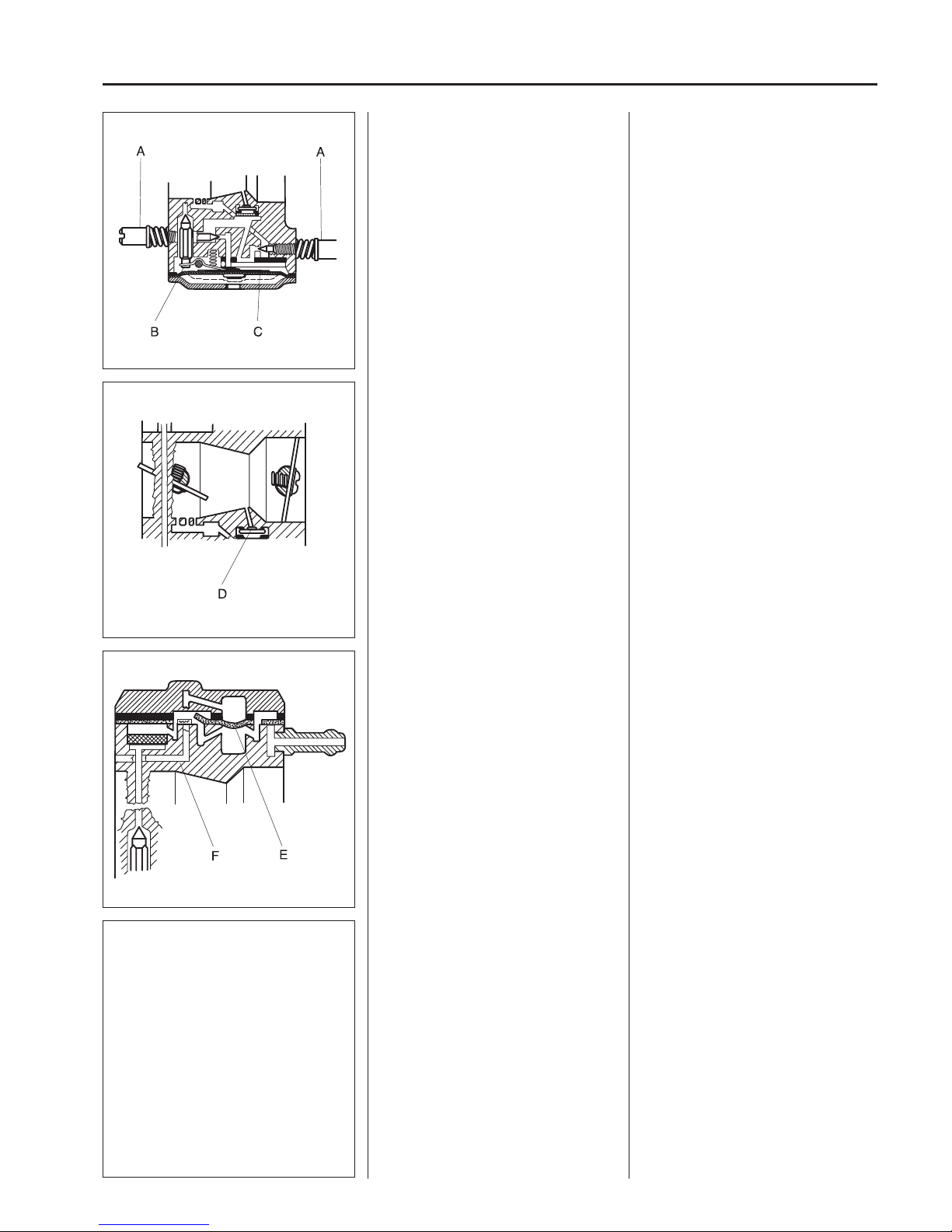
The carburettor’s design
The carburettor can be divided into
three di erent functional units: the
metering unit, the blending unit, and the
pump unit.
The metering unit
The needles and the fuel control functions are located here.
The carburettor’s design
The carburettor can be divided into
three di erent functional units: the
metering unit, the blending unit, and the
pump unit.
The metering unit
The needles (A) and the fuel control
functions are located here.
The needle valve (B) and control
diaphragm (C) are vital to the
carburettor’s function.
The blending unit
Fuel and air are mixed here.
The blending unit
In this section of the carburettor fuel and
air are mixed in the proper proportions.
The choke and throttle valves are placed here.
In the middle of the venturi (narrowest
part of the throughput) the main jet (D)
is found.
The pump unit
Pumps fuel from the tank to the carburettor.
The pump unit
This is where the pump diaphragm (E)
that pumps fuel from the tank to the
carburettor’s measuring unit is found.
The diaphragm is a ected by pressure
variations in the engine’s crankcase via
an impulse channel (F).
If the channel is blocked, by grease or
a wrongly facing gasket, for example,
the pump unit does not function and the
engine cannot be started.
Page 23
22
3
Fuel system
531 03 06-23
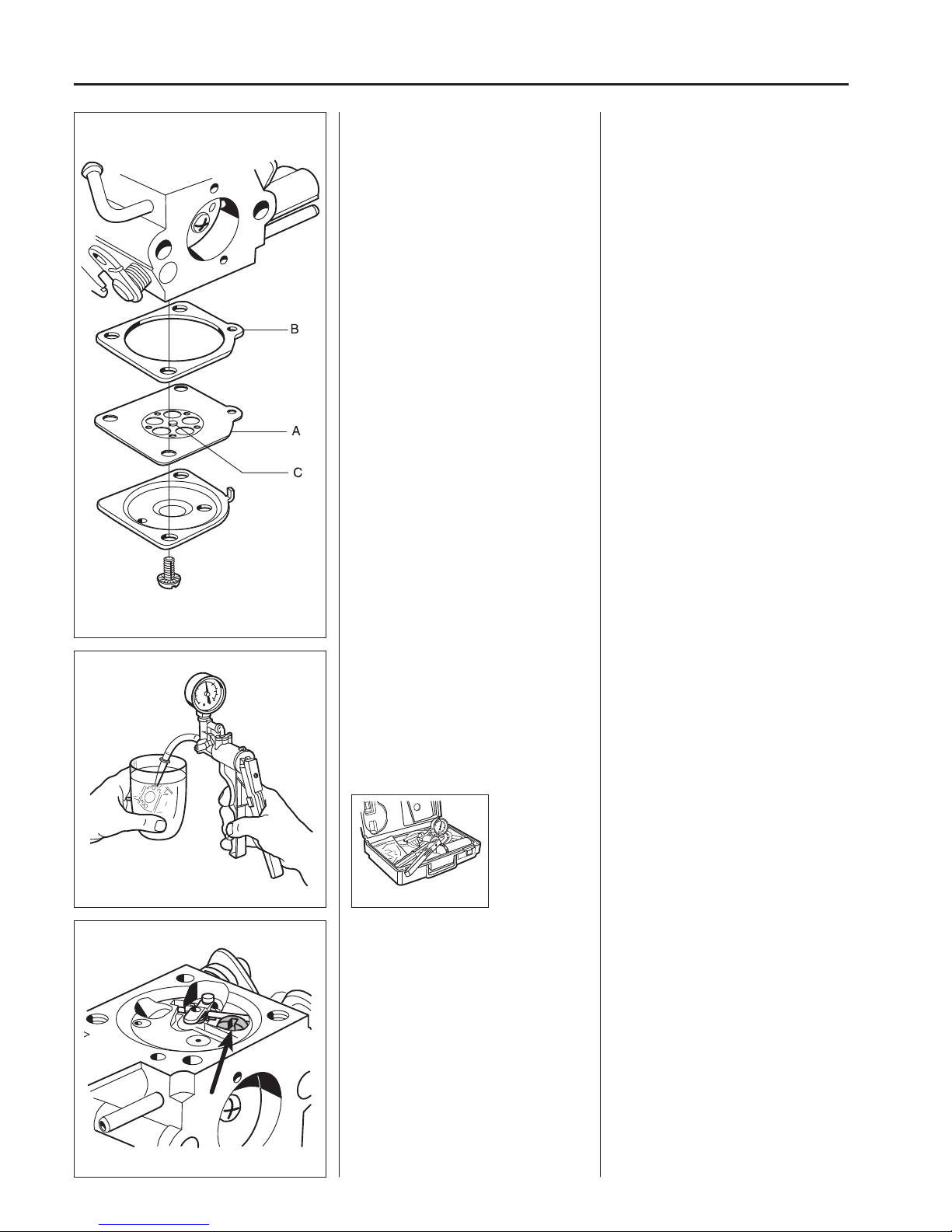
Dismantling the carburettor
Remove the control diaphragm and
check for damage.
Replace if required.
Dismantling the carburettor
Unscrew the 2 bolts that hold the control
diaphragm cover and lift o the cover.
Carefully remove the control diaphragm
(A) and gasket (B).
Check the diaphragm for holes and
wear on the pin (C).
Replace the diaphragm if required.
Pressure test the metering unit.
Connect pressure tester 531 03 06-23 to
the fuel hose nipple.
Lower the carburettor in a vessel with
petrol in order to discover any leaks
more easily.
Test the pressure at 50 kPa.
No leakage is permitted.
In the event of leakage – remove the
needle valve.
In the event of leakage – remove the
needle valve.
Loosen the bolt and remove the lever
arm, axle, needle valve and spring.
Page 24
23
3
Fuel system
504 62 29-01
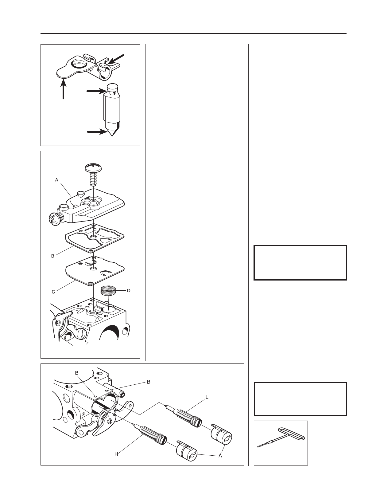
Pull the locking plugs (A) o over the jet
needles with the help of special tool 504
62 29-01 (left-hand threads) or screw
503 21 29-10 that holds the guard that is
screwed on the cylinder cover.
The plugs cannot be dismantled if the
slot in the plug is centred above the ball
(B) in the carburettor housing.
Unscrew the jet needles.
NOTE!
Note how the jets are positioned.
(For example, the H-needle is a
little shorter than the L-needle).
Check the needle valve and the lever
arm for damage or wear.
Replace damaged components with
new ones.
Check the needle valve for damage on
the tip and in the lever arm groove.
Check the lever arm for damage to the
groove for the needle valve and wear on
the mounting points towards the control
diaphragm.
Replace damaged components with
new ones.
Remove the pump diaphragm.
Check the diaphragm for damage.
Remove the fuel screen and clean it or
attach a new one.
Remove the bolt holding the cover over
the pump diaphragm.
Lift o the cover (A), the gasket (B) and
the diaphragm (C).
Check the diaphragm for damage to
the valve tongues. If the valve tongues
are bent, the pump will not function in a
satisfactory manner.
Hold it up to a light as well to discover
any holes in the material.
Carefully remove the fuel screen (D),
using a needle for example. Clean or
replace the fuel screen.
NOTE!
During assembly the pump
diaphragm should lie closest
to the carburettor housing.
Page 25
24
3
Fuel system
333/335
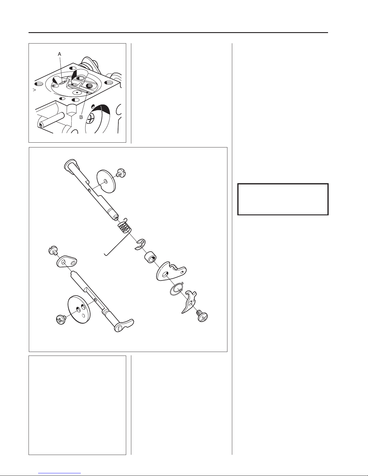
Remove the valves and dampers. If
these components are worn, idling is
disrupted.
Always replace the valves and dampers
at the same time.
NOTE!
Do not lose the ball and spring in
the carburettor housing where the
choke shaft is stored.
Note how valves and recoil springs are
tted.
Dismantle the main jet (A) and the plug
(B).
Press out the main jet (A) with a suitable
punch.
Remove the plug (B).
Carefully drill a small hole (Ø 2 mm)
in the plug and pry it up with a pointed
object.
Page 26
25
3
Fuel system
336
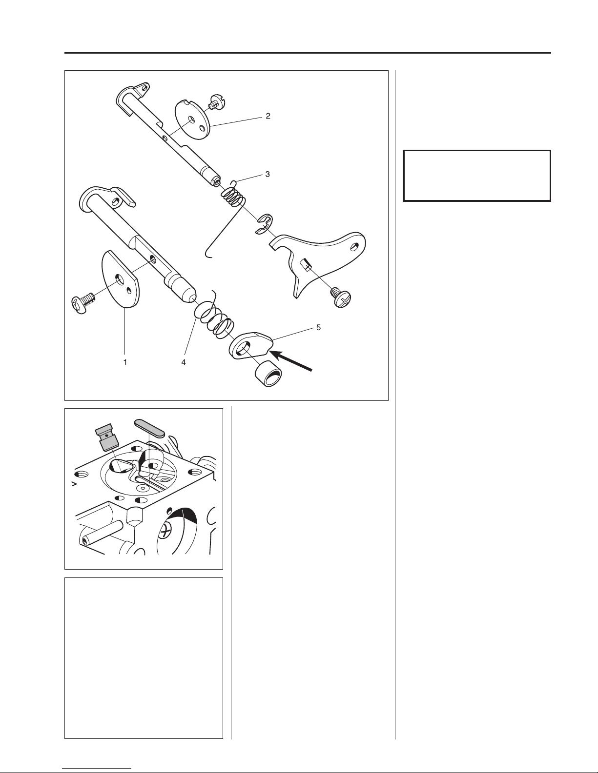
Remove the valves and dampers. If
these components are worn, idling is
disrupted.
Note how the choke valve (1), the throttle valve (2), the recoil springs (3) and
(4) and the lever arm (notched by the
arrow) (5) are tted.
NOTE!
Do not lose the ball and spring in
the carburettor housing where the
choke shaft is stored.
Always replace the valves and dampers
at the same time.
Assembling the carburettor
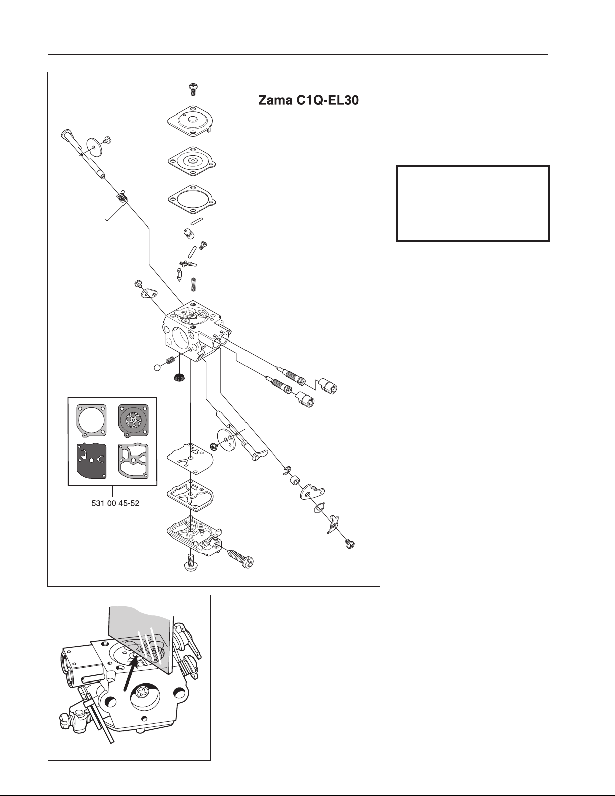
• Blow all channels in the carburettor
compartment clean
• Mount a new plug.
Use a suitable punch to get a com-
pletely tight seal.
• Press in a new main jet.
Assembling the carburettor
Blow the carburettor housing clean.
Fit a new plug.
Fit a new main jet.
Page 27
26
3
Fuel system
• Mount the valves and dampers.
Replace the fuel screen if it is damaged
or cannot be cleaned.
Place the pump diaphragm closest
to the carburettor housing. Then
the gasket and cover and the other
components in reverse order of
removal.
NOTE!
Check that the valves are turned
correctly and that they close
completely and tightly in the
closed position.
Use Loctite on the valve screws.
Attach the various parts of the
measuring unit in the reverse order as
set out for dismantling.
The lever arm should lie ush with the
carburettor housing.
Attach the various parts of the
measuring unit in the reverse order as
set out for dismantling.
The lever arm should lie ush with the
carburettor housing.
Too high setting = too much fuel.
Too low setting = too little fuel.
Page 28
27
3
Fuel system
531 03 06-23
504 62 29-01
NOTE!
The H-needle is a little shorter
than the L-needle.
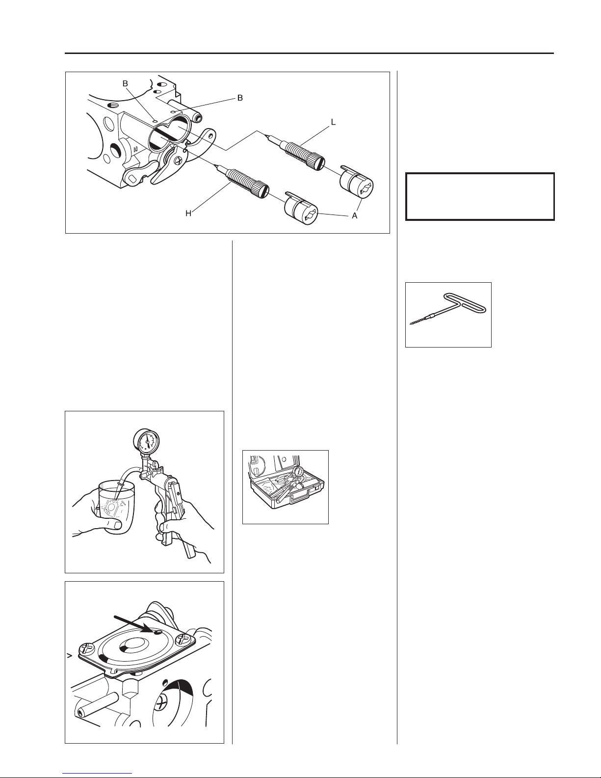
Fit the jet needles and adjust their setting.
Model H L
135 2.0 0.75
333 2.0 (EL-36D) 1.0 (EL-36D)
335 2.0 (EL-36D) 1.0 (EL-36D)
336 2.0 0.75
535 2.0 (EL-36D) 1.0 (EL-36D)
Press the stop plugs (A) in position
using tool 504 62 29-01. Check that the
O-ring is correctly seated and that the
slot in the plug aligns with the ball (B) in
the carburettor housing.
Check that the carburettor is sealed.
No leakage is permitted at 50 kPa.
Connect pressure tester 531 03 06-23
to the fuel intake on the carburettor.
Pump up the pressure to 50 kPa.
Lower the carburettor in a vessel with
petrol in order to discover any leaks
more easily.
No leakage is permitted.
Attach the control diaphragm and cover. Place the gasket on the carburettor
housing and then the control diaphragm.
Check that the air hole in the cover is
open and screw the cover on.
Page 29
28
3
Fuel system
502 50 18-01
333/335
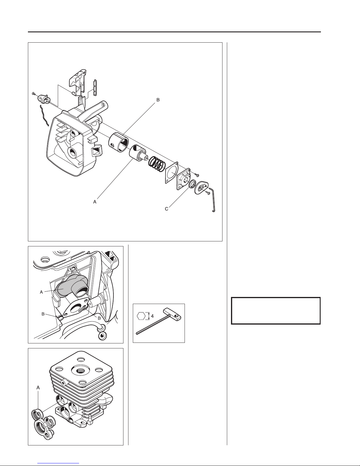
The holder for the air lter contains a
device that opens two air ducts in the
cylinder during acceleration. A rotary
valve connected to the throttle valve
lever opens the air supply in proportion
to the acceleration.
The device has the task of preventing
uncombusted fuel/air mixture from going
directly out into the exhaust channel.
The result is cleaner exhaust fumes and
more e ective utilisation of the fuel.
Check the wear on the rotary valve (A)
and its bearing sleeve (B). Also make
sure that the sealing ring (C) is not
damaged.
Check the rubber connection on the
distance piece/heat shield for leakage.
Remove the screws (B) holding the heat
guard.
Check that the rubber connection (A) on
the distance piece/heat shield does not
show signs of cracking or in any other
way leaks. Replace the connection if
this is the case.
Remove the screws (B) holding the heat
guard against the cylinder and pry o
the guard.
NOTE!
Do not lose the brass sleeves tted
in the guard.
Dismantle and inspect the rubber connection (A) for damage.
Carefully dismantle the rubber connection (A) from the cylinder and check for
damage that can cause leakage.
Replace the connection if necessary.
Page 30
29
3
Fuel system
333/335
336
Assembly
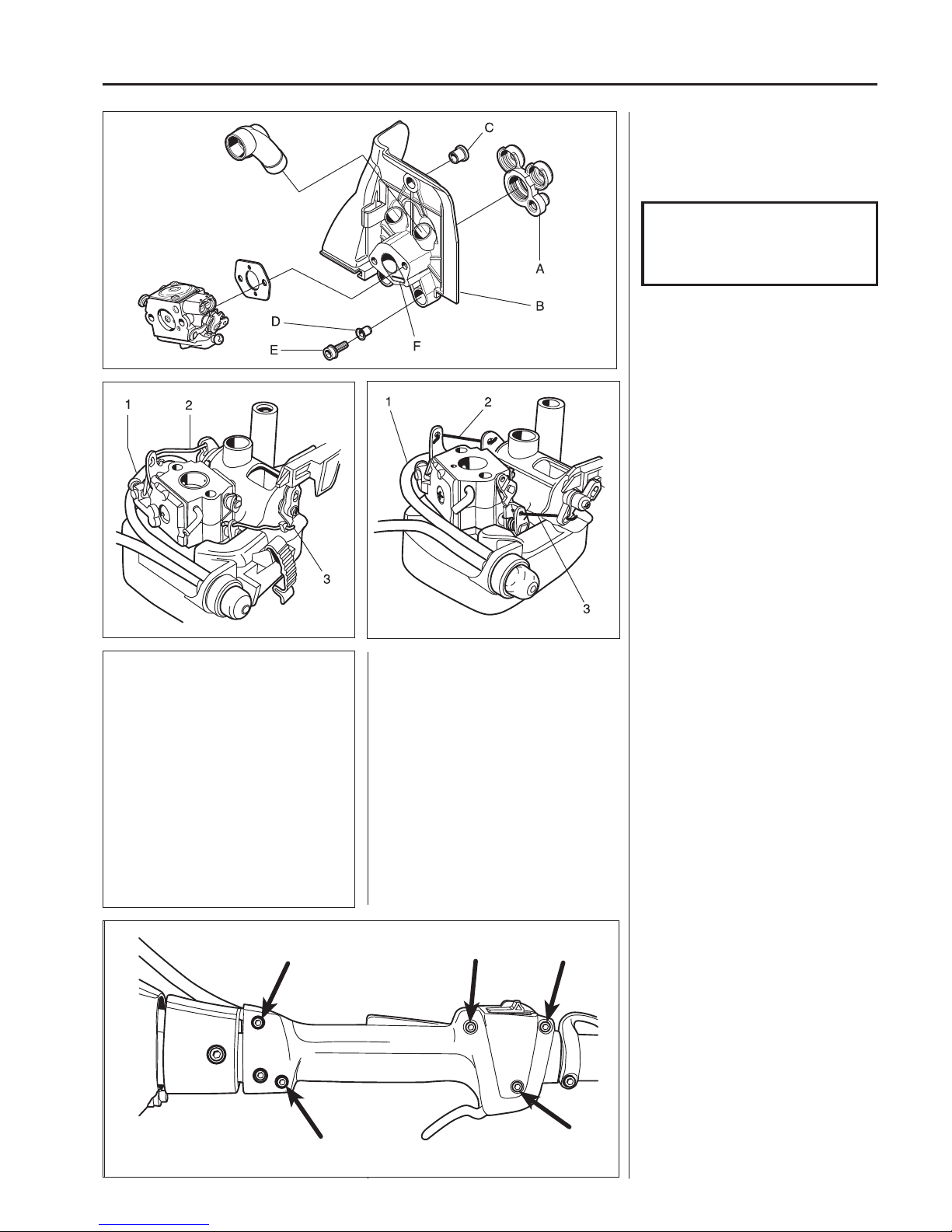
1. Fit the rubber connection (A) on
the cylinder. Lubricate with silicone
spray or washing-up liquid so it
slides easily into the holes.
Throttle
(model Lx, RJ, RJx)
Remove the ve screws holding together the throttle halves.
Carefully swing away the right throttle
half and note how the di erent parts are
tted.
Model 333/335
3. Fit the fuel hose (1) and both pressure rods (2) and (3).
4. Place the carburettor in the air
lter cowling and located it with the
screws.
Model 336
3. Fit the longer pressure rod (2) rst
on the carburettor followed by the
supply air valve.
4. Place the carburettor in the air lter
cover and connect the choke pressure rod (3) to the lever arm on the
carburettor rst.
Then press it down into the groove
in the lever arm by the choke control.
Connect the fuel hose (1) to the
carburettor.
5. Insert the remaining fuel hose into
the tank.
6. Place the carburettor gasket in position and tighten the carburettor with
the two screws.
7. Tighten the upper screw on the air
lter cowling in the heat guard.
Do not forget the washer under the
screw head.
8. Connect the throttle cable.
Assemble the remaining parts in the
reverse order as set out for dismantling.
NOTE!
Do not lubricate the rubber
connection with oil as this can
cause the rubber to swell.
2. Fit the heat shield (B). Lubricate the
connection sleeves with silicone
spray or washing-up liquid so that
they slide into the rubber connection.
Check that the bush (C) and brass
sleeves (D) are seated correctly.
Check that the impulse channel (F)
is fully open.
Tighten the screws (E).
Page 31
30
3
Fuel system
Throttle
(model R, Rx)
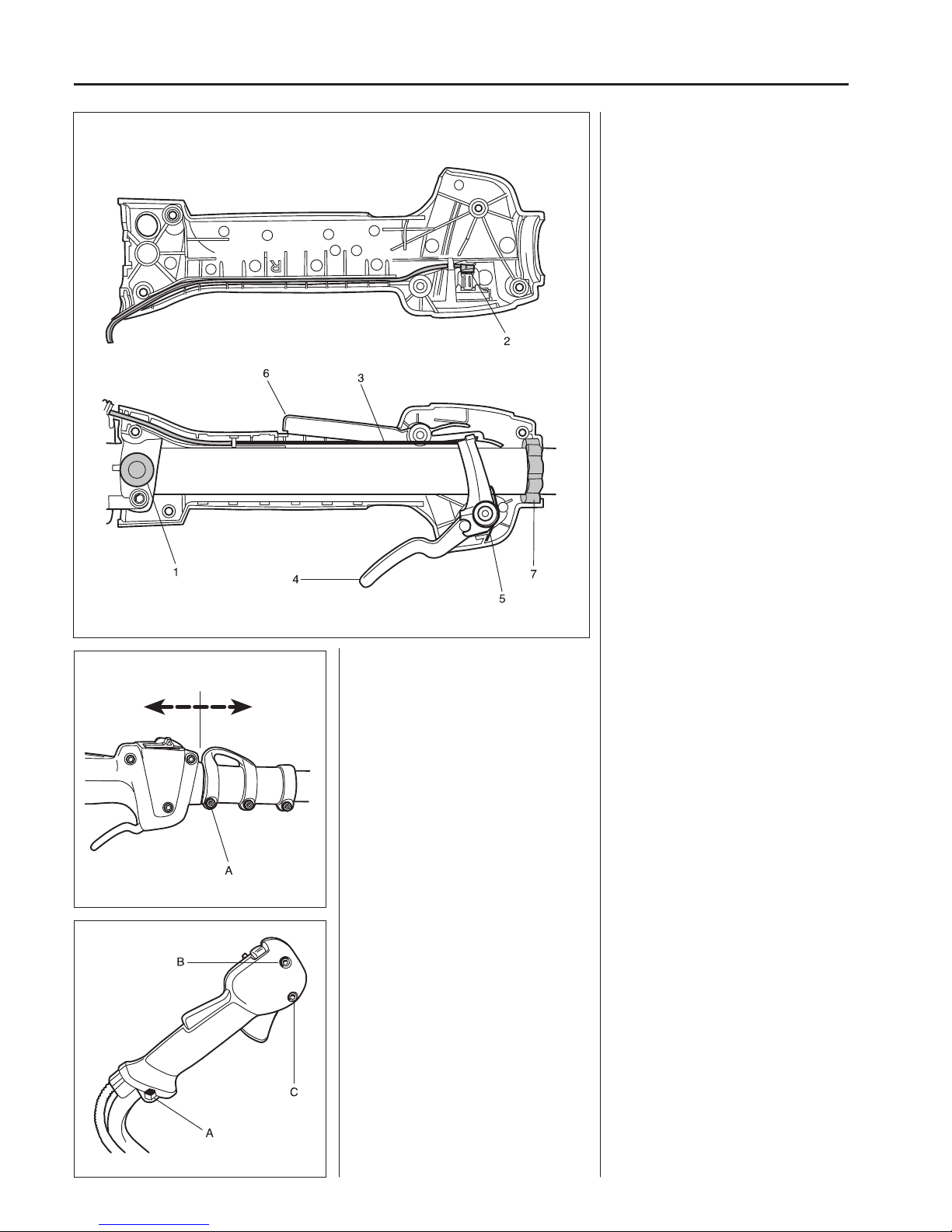
Remove the bolt (A) and remove the
throttle from the handle.
Remove bolts (B) and (C).
Separate the halves of the throttle.
Throttle
(model R, Rx)
Remove the bolt (A) that attaches the
throttle to the handle.
Be careful not to lose the nut.
Remove the throttle and remove bolts
(B) and (C).
Carefully separate the two halves of the
throttle.
Pay attention when the halves are separated so that both rubber elements (1),
one on each side, are not lost.
Remove the short-circuit cable from the
switch (2).
Lift up the throttle cable (3) from the
channel and unhook it from the throttle
(4).
Lift o the return spring (5) and note
how it is placed.
Remove the lock for unintentional throttle activation (6).
If the front vibration damper (7) is to be
replaced, the shaft must be split. See
below.
Split the shaft.
Separate both halves of the throttle.
Slide the front vibration damper (7) o of
the shaft.
Assemble in the reverse order as set
out for dismantling.
Loosen the screw (A) and pull away the
front part of the two-piece shaft.
Separate the throttle halves as described above.
The front, ring shaped vibration damper
(7 in the illustration above) can now be
slid o of the shaft for replacement.
Assemble the throttle in the reverse
order as set out for dismantling.
Make sure that:
• The throttle return spring is turned the
right way.
• The washer under the lock for unintentional throttle activation is seated
correctly.
• Both rear rubber elements are in position.
Page 32
31
3
Fuel system
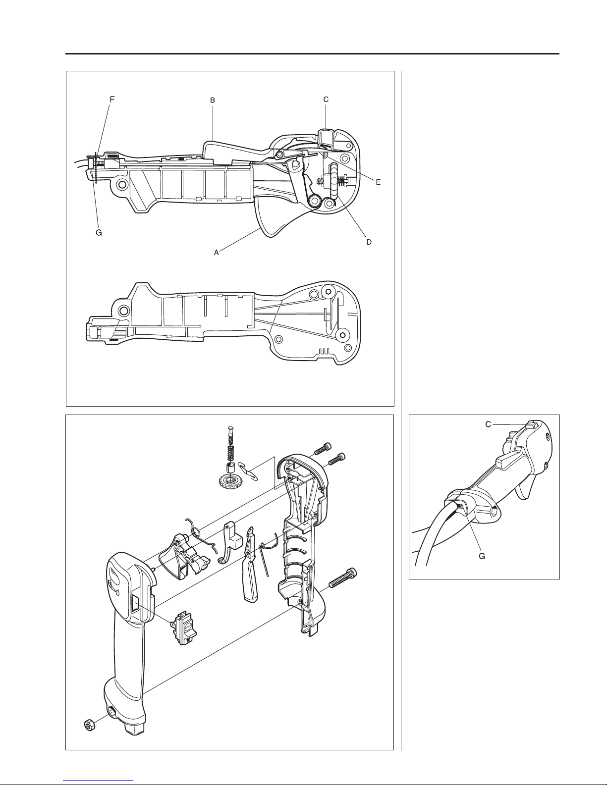
Disassemble the throttle control (A), the
lock to prevent accidental throttle operation (B), the start throttle lock (C) and
the throttle stop (D) in order to check if
replacement is necessary.
The stop switch can also be disassembled now, and replaced if necessary. Use
a screwdriver to press the stop switch’s
wing locks (E).
G = Adjuster screw for start throttle
speed.
Tip!
Reassembly of the throttle easier if a
thin steel wire is wrapped around the
handle and bolt (F) in order to hold the
throttle cable and short-circuit cables in
place.
Start throttle speed
The start throttle speed can be adjusted
using screw (G)
Proceed as follows:
1. Start the engine and let it idle.
2. Press down the start throttle lock
(C).
3. When the start throttle speed is too
low (below 4000 rpm), screw the adjuster screw (G) clockwise until the
cutting equipment starts to rotate.
Now screw clockwise a further 1/2
turn.
4. When the start throttle speed is too
high, screw the adjuster screw (G)
anti-clockwise until the cutting equipment stops. Now screw clockwise a
further 1/2 turn.
Page 33
32
3
Fuel system
333/335
336
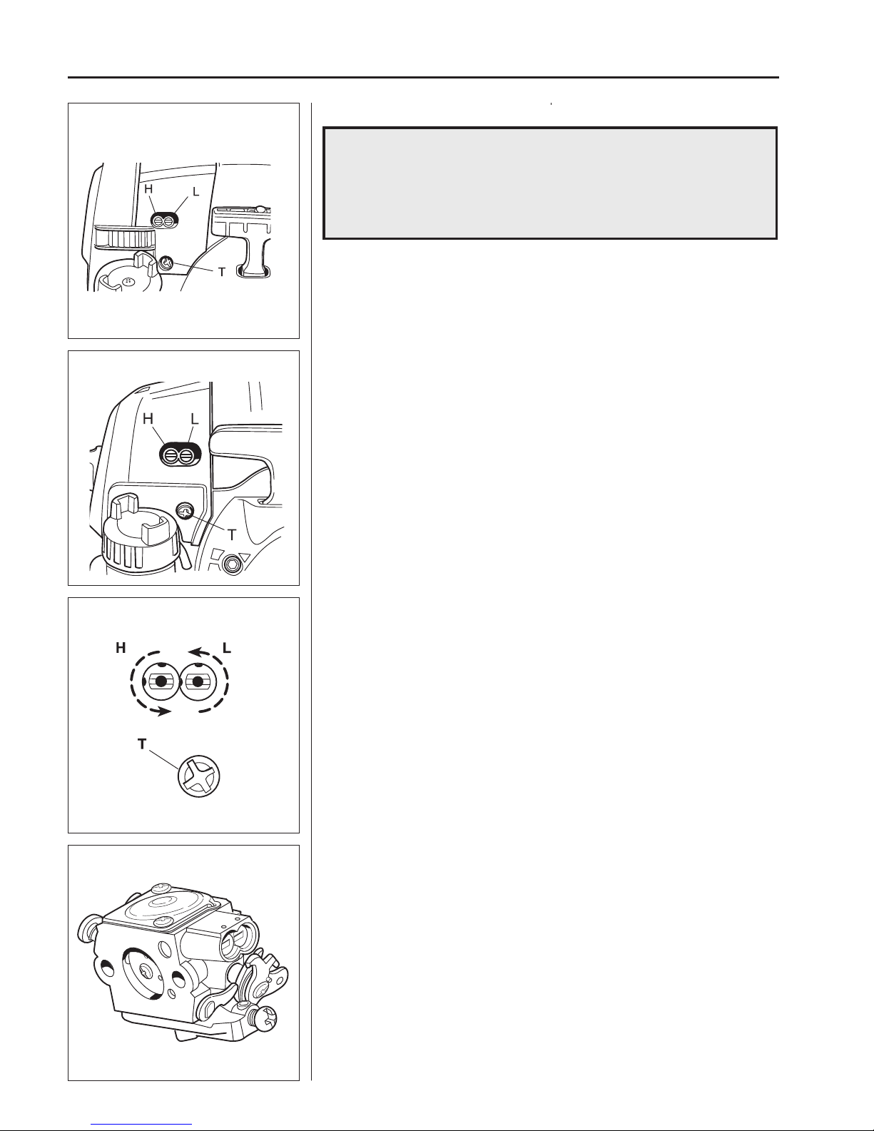
The needles must be correctly adjusted in order for the engine to give maximum
power at di erent speeds, run steadily while idling and to react quickly when accelerating.
The setting of the carburettor can vary a little depending on the humidity, temperature
and air pressure.
L = Low speed needle
H = High speed needle
T = Idle adjustment screw
• The fuel quantity in relation to the air ow permitted by the throttle opening is adjusted by the L and H jets. Turning the needles clockwise gives a leaner fuel mixture
(less fuel) and turning them anticlockwise gives a richer fuel mixture (more fuel). A
leaner mixture gives higher revs while a richer mixture gives less revs.
• The T-screw regulates the position of the throttle while the engine is idling. Turning the screw clockwise gives a higher idling speed while turning it anticlockwise
gives a lower idling speed.
Carburettor settings
Function
The carburettor has the task of supplying a combustible fuel/air mixture to the cylinder.
The amount of this mixture is controlled by the throttle.
The mixture’s composition of fuel and air is controlled by means of the adjustable “H”
and “L” needles.
WARNING!
When testing the engine in connection with carburettor
adjustment, the clutch and clutch cover must be mounted together
with the shaft and angle gear under all circumstances
Otherwise there is a risk of the clutch becoming loose resulting in
serious personal injury.
!
Basic setting
The carburettor is set to its basic setting when test run at the factory. The basic setting is “richer” than the optimal setting (fast idle speed is 600–800 rpm under the recommended max. speed) and should be kept during the engine’s rst working hours.
Thereafter the carburettor should be ne tuned.
The default setting is:
Model H L
135 2.0 0.75
333 2.0 (EL-36D) 1.0 (EL-36D)
335 2.0 (EL-36D) 1.0 (EL-36D)
336 2.0 0.75
535 2.0 (EL-36D) 1.0 (EL-36D)
The H and L needles on the carburettor can be adjusted within extremely tight limits,
to among others, comply with the stringent demands with regard to the hydrocarbon
and nitrogen oxide content in the exhaust fumes.
The carburettor needles on these carburettors are blocked with locking plugs.
To carry out adjustment when replacing needles or the entire carburettor the engine
must be under load. This is achieved by tting a standard trimmer with the speci ed
length (de ned by the blade on the trimmer guard) and diameter of the trimmer cord.
Consequently, the stated speed will be much lower than with ”normal” carburettor
adjustment when the engine may run freely.
After replacing the needles or the entire carburettor on a CARB-EPA approved
engine, adjustment must be carried out according to the instructions below.
The combiguard or trim guard must be tted when adjusting the H-needle.
Page 34
33
3
Fuel system
531 00 48-63
504 62 29-01
502 71 14-01
H
L
NOTE!
If the cutting equipment rotates while idling the
T-screw should be turned anticlockwise until it stops.
A tachometer should always be used to nd the
optimal setting.
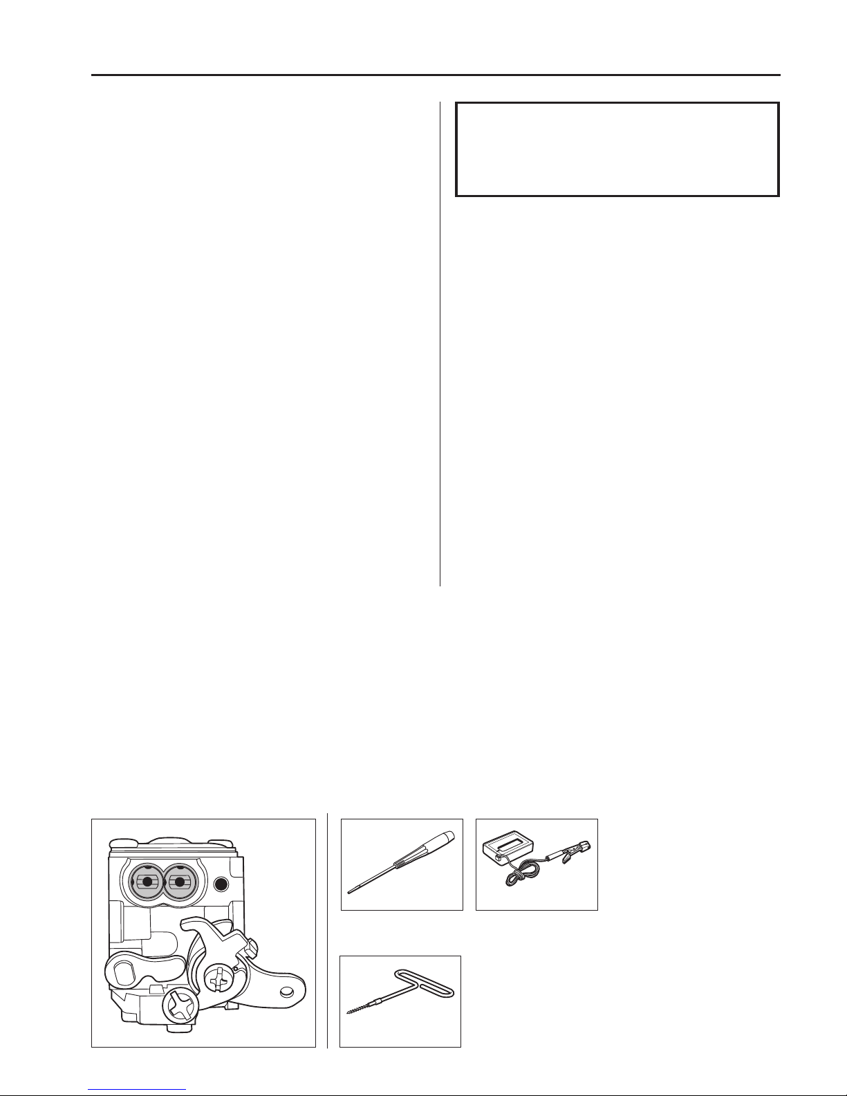
Using a screwdriver 531 00 48-63 it is possible to make
small adjustments to the jet needles without the need of
removing the locking plugs.
Use the tool 504 62 29-01 to dismantle the locking plugs
(left-hand threads) so the needles can be screwed out,
e.g. for replacing or cleaning.
Fine adjustment
Fine adjustment of the carburettor should be carried out after
the engine has been “run-in”. It is important that the air lter is
clean and that the carburettor cover is tted when adjusting the
carburettor.
The engine must be run warm at full throttle which is approx.
11,000 rpm (electronic speed limitation). Run the engine for 4 to
5 minutes to make sure it is warm.
Then adjust the carburettor needles in two steps as follows:
First adjustment
1. Turn the L needle clockwise until the top idle speed is
reached. If the trimmer head then rotates, reduce the speed
by turning the idle screw (T) anticlockwise until it stops rotating.
2. Turn the H needle at full throttle to the position where the
engine starts running as a 4-stroke.
3. Stop the engine.
Second adjustment
1. Start the engine (still warm).
2. Turn the L needle anticlockwise so that the speed drops by
500 rpm.
3. Stop the engine.
4. Turn the H needle a 3/4 turn clockwise (half a turn for models
135 and 336).
5. Then adjust the idling speed to 2,900 rpm by turning the idle
screw (T).
After adjustments are made, the sleeve on each needle must be
tted so that they cannot be turned anticlockwise (“richer” fuel-air
mix).
Correctly adjusted carburettor
A correctly adjusted carburettor means that the engine accelerates without hesitation and it four-strokes a little at full
throttle.
• The cutting equipment must not rotate while idling.
• A too lean adjusted L-needle can cause starting di culties
and poor acceleration.
• A too lean adjusted H-needle results in lower power, poor
acceleration and/or damage to the engine.
• A too rich setting of the “L” and “H” needles give acceleration problems or a too low working speed.
Idling speed T-screw
Let the engine idle for about 30 seconds or until the speed
has stabilised. Adjust the idling speed T-screw until the engine
idles without stopping.
• Turn the screw clockwise if the engine stops.
• Turn the screw anticlockwise to lower the speed.
Page 35

34
3
Fuel system
Page 36
35
4
Centrifugal clutch
4
Contents
Centrifugal clutch – Dismantling ____________________ 36
Centrifugal clutch – Assembly ______________________ 37
Clutch drum and drive axle – Dismantling ____________ 37
Clutch drum and drive axle – Assembly ______________ 39
Centrifugal clutch
Page 37
36
4
Centrifugal clutch
E
E
E
333/335 336
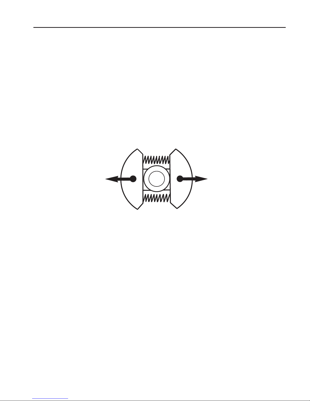
The centrifugal clutch has the task of transferring the power from the engine to the cutting equipment’s
drive axle. As the name implies, it works according to a centrifugal principle.
This means the clutch’s friction shoes are thrown outwards towards the clutch drum at a certain engine
speed. When the friction against the drum is su ciently great it drives the drive shaft at the same speed as
the engine.
Some slipping occurs between the clutch and the clutch drum when accelerating as well as in the reversed
situation when the cutting equipment jams. Thereby preventing abnormal load changes on the crankshaft.
The engagement speed has been carefully tested so that the engine can idle without the cutting
equipment’s drive shaft rotating.
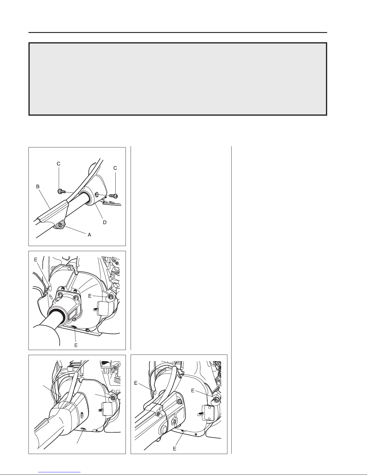
Dismantle the protective cover under
the engine.
Remove the 3 screws (E) and swing the
engine body to one side so the centrifugal clutch becomes accessible.
Dismantling opt. B
Remove the protective plate under the
engine body (3 or 4 screws).
Lift out the ignition lead and short-circuit
cables from their guides.
Remove the 3 screws (E) and swing the
engine body to one side so the clutch
becomes accessible.
Centrifugal clutch
Dismantling opt. A
Remove the cover over the air lter,
cylinder cover and the cover over the
mu er.
Loosen the screw and slide the cable
holder (B) forwards.
Remove the screws and slide the cover
(D) forwards.
Centrifugal clutch
Dismantling opt. A
Remove the cover over the air lter,
cylinder cover and the cover over the
mu er.
Loosen the screw (A) and slide the cable holder (B) forwards on the shaft.
Remove the screws (C) and slide the
cover (D) forwards on the shaft.
Dismantle the protective cover under the
engine.
Remove the 3 screws (E) and swing the
engine body to one side.
Page 38
37
4
Centrifugal clutch
502 50 18-01
336333/335
Clutch drum and drive
axle
Dismantling
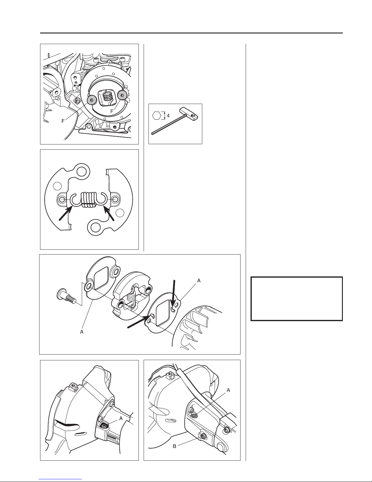
Loosen the screw (A), screws (B) and
pull o the shaft from the connection
sleeve.
Twist apart the clutch and inspect the
di erent parts with regard to wear or
damage.
Twist apart the clutch.
Inspect the di erent parts with regard to
wear or damage.
Pay special attention to the ends of the
springs, which in addition to wear, can
also show signs of cracking.
Assembly
Connect the clutch shoes together with
the spring.
NOTE!
Both clutch shoes should be
replaced even if only one of them is
showing signs of heavy wear. This
is to avoid engine vibration caused
by imbalance in the clutch.
Bolt the clutch on the ywheel. Do not
forget the washers (A).
Note the slots on the washer lie closest
to the ywheel. Align with the equivalent
pins on the ywheel.
Remove both screws (F) holding the
centrifugal clutch.
Lift o the clutch and both support
washers.
Dismantle the centrifugal clutch.
Page 39
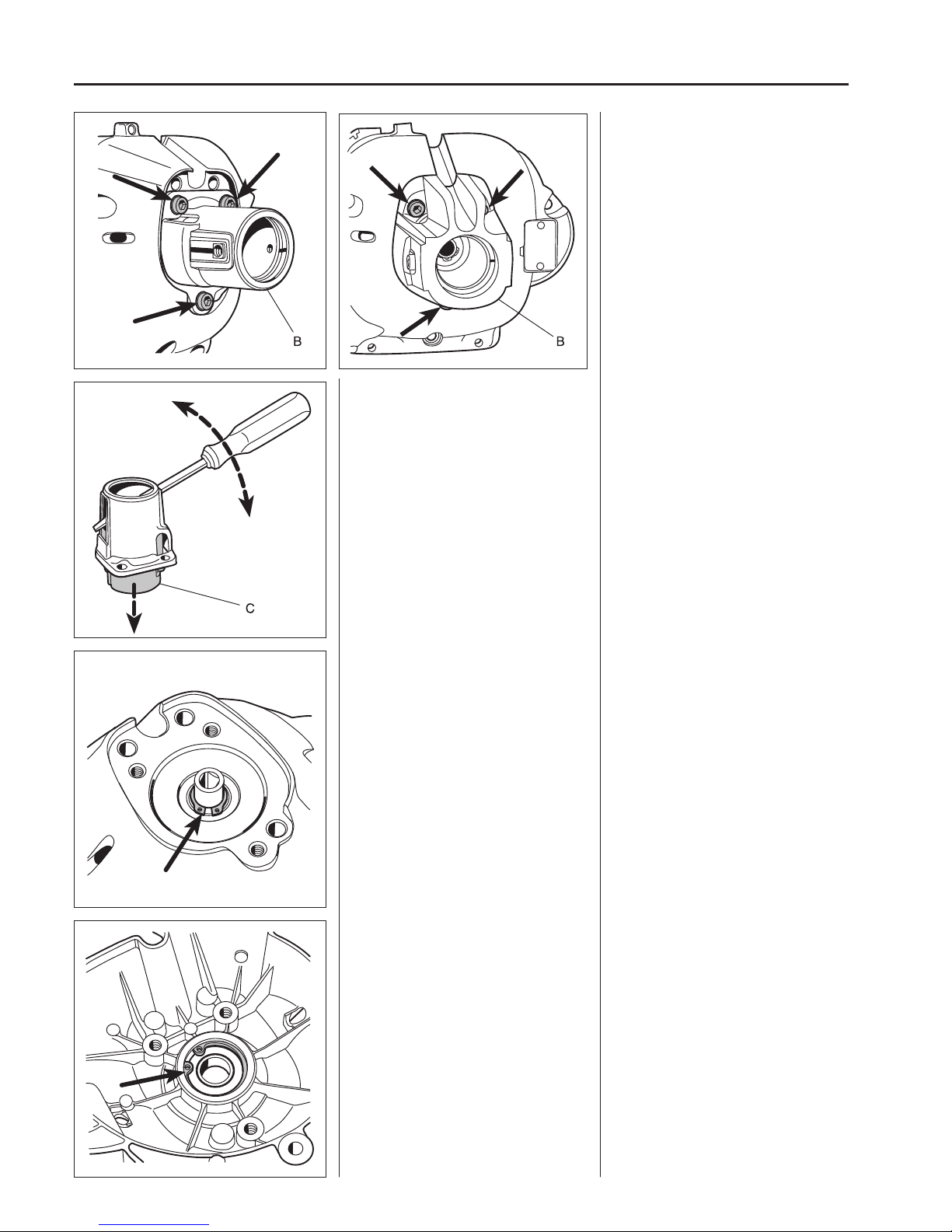
38
4
Centrifugal clutch
336333/335
333/335
Dismantle the vibration element (C)
together with the clamping sleeve for
possible replacement.
Press the vibration element (C) together
with the clamping sleeve out from the
connection sleeve with the help of a
screwdriver for possible replacement.
Dismantle the circlip and press out the
clutch drum.
Dismantle the circlip using circlip pliers.
Press out the clutch drum using a suitable punch and hammer.
Dismantle the circlip and heat the clutch
cover so the bearing can be dismantled.
Dismantle the circlip using circlip pliers.
Heat the clutch case to approx. 120°C
using a hot air gun.
Knock the edge of the cover against a
wooden block so the ball-bearing falls
out or use a hammer and punch.
Remove the 3 screws and lift the connection sleeve (B) o of the clutch
housing.
Page 40
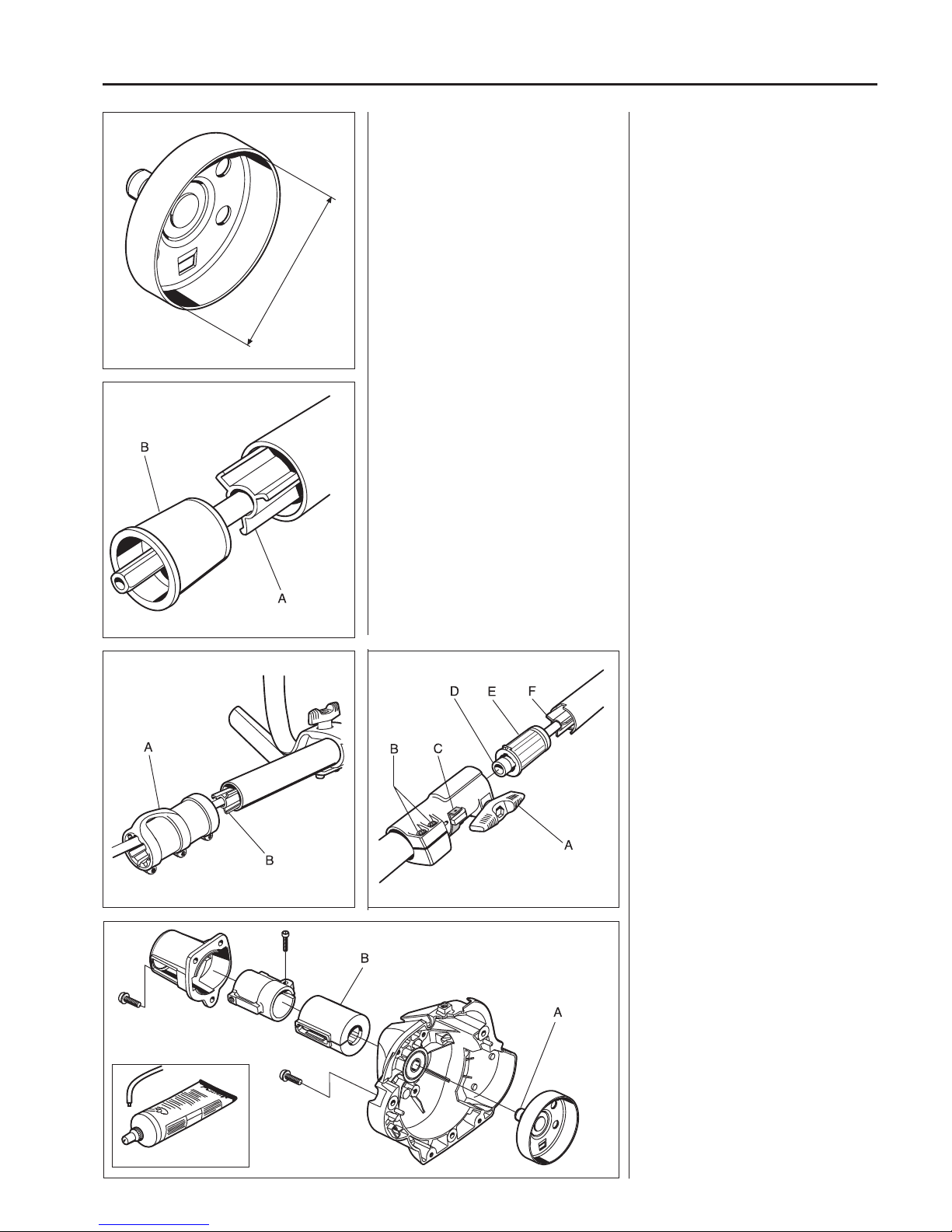
39
4
Centrifugal clutch
max. Ø 64.0 mm
503 80 17-01
336333/335
(mod. L och RJ)
333/335
Assembly
Assemble in the reverse order as set out
for dismantling.
Check that the circlips are tted correctly
in respective slots.
Lubricate the hole (A) in the clutch
drum’s connection on the drive axle
using copper paste to aid assembly and
dismantling in the future.
Rub the vibration element (B) with talc so
that it slides into position easier.
Lubricate the drive axle with grease no.
503 80 17-01 when assembling in the
guide.
Model 333/335
On models with a two-piece shaft, the
guide becomes accessible once the
shaft has been split (see chapter 3).
Dismantle the sleeve (A) and pull out
the guide (B) by pulling the drive axle.
Model 336
Loosen the turn handle (A) and both
screws (B). Press down the locking
spring (C) and seperate the shaft.
Pull out the drive axle (D) and remove
the sleeve (E) with the help of a screwdriver. This makes the guide for the
drive axle (F) accessible if it must be
replaced.
The shaft contains a long guide for the
drive axle.
Dismantling for possible replacement is
done by rst removing the plastic sleeve
(B).
The drive axle is guided in the shaft
with the help of a star shaped guide (A)
which the axle runs through. This prevents axle oscillation, which in turn can
cause vibration.
The axle and guide can easily be pulled
out of the shaft once the sleeve (B) is
pried o with a screwdriver.
Check the inside diameter of the clutch
drum. If it exceeds 64.0 mm it should be
replaced.
Check the clutch drum for wear.
The diameter must not exceed 64.0
mm. If this is the case replace the clutch
drum.
Page 41

40
4
Centrifugal clutch
Page 42
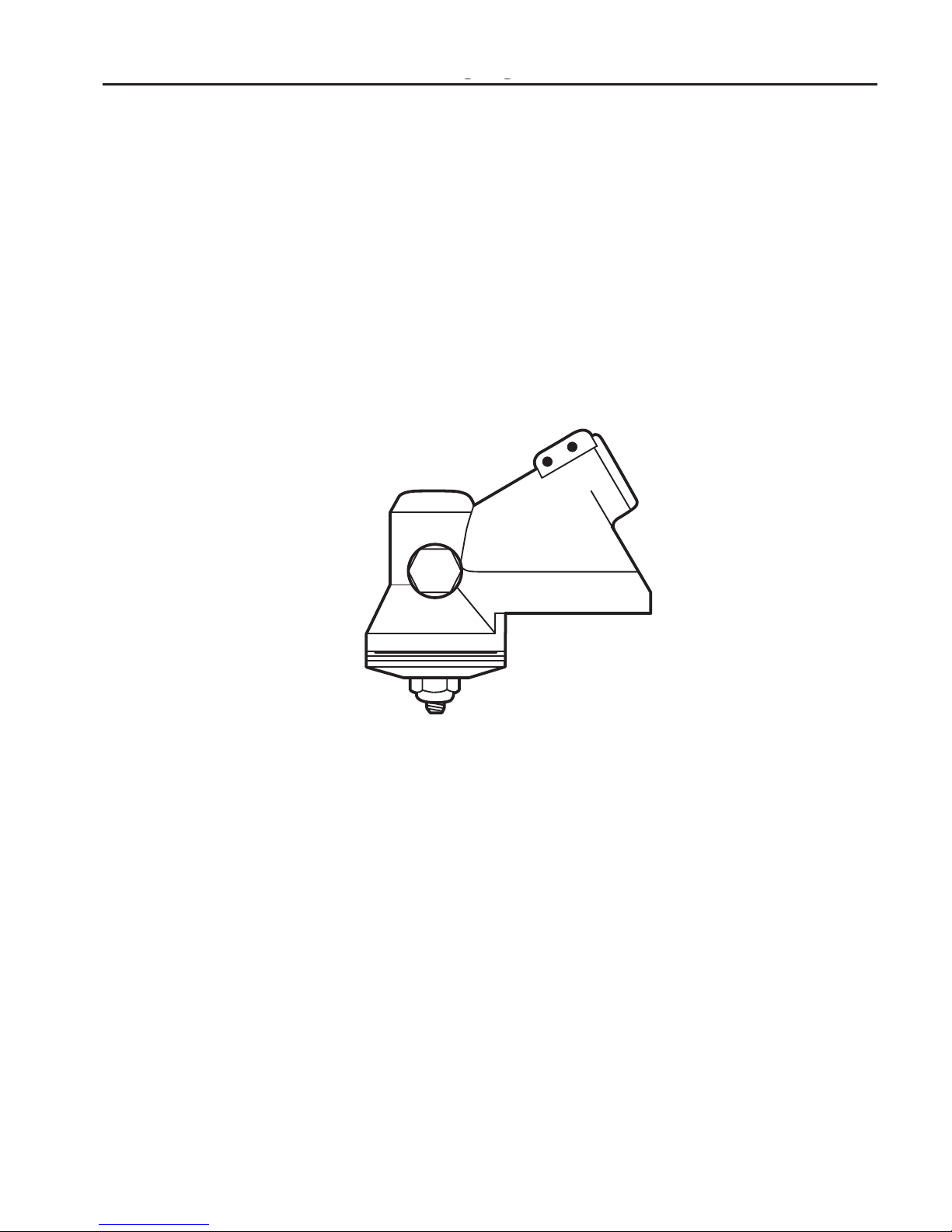
41
5
Angle gear
5
5
Contents
Gear ratio ______________________________________ 42
Dismantling ____________________________________ 42
Assembly_______________________________________ 43
Drive axle, dismantling ____________________________ 43
Drive axle, assembly _____________________________ 44
Angle gear
Page 43
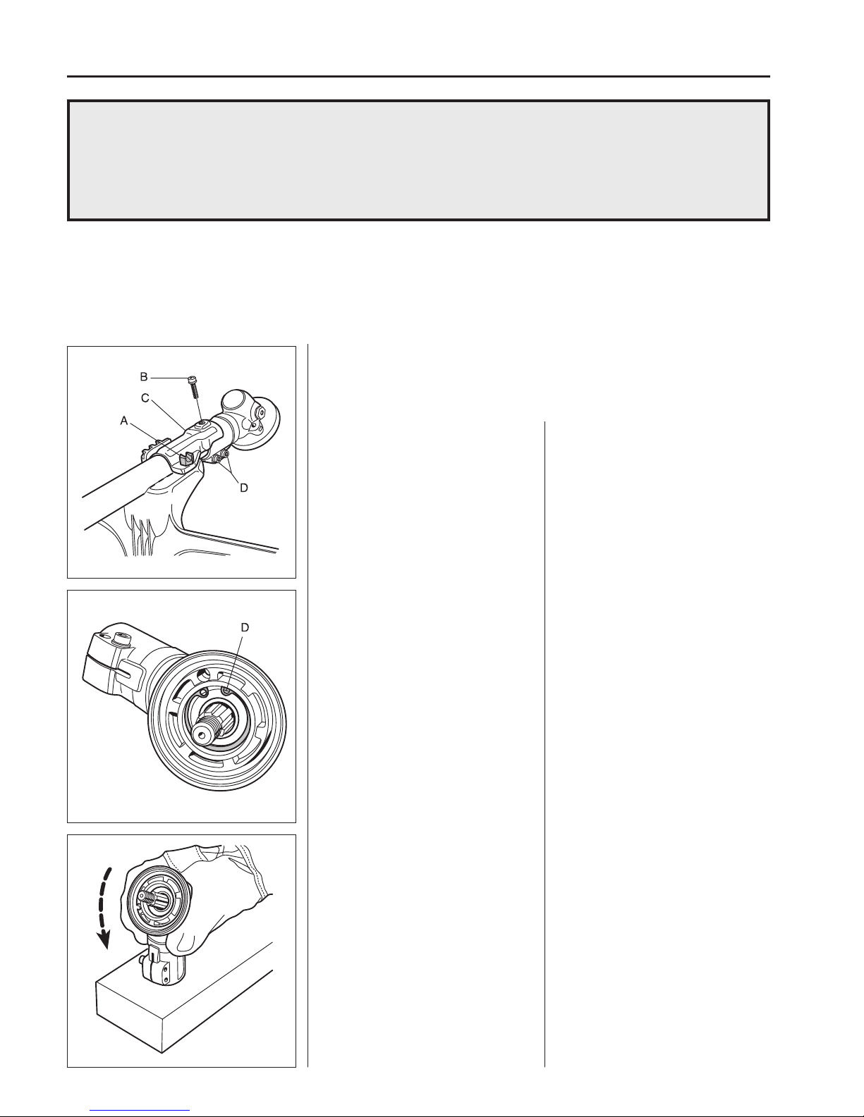
42
5
Angle gear
Gear ratio
Model Lx, RJ, RJx: 1:1.29 (black grease plug).
Model R, Rx: 1:1.4.
Dismantling
Remove the cutting equipment and
guard.
1. Remove the screws (A) and (B) and
lift o the plate (C).
2. Loosen the screws (D) and pull the
angle gear from the shaft.
The angle gear has two purposes:
The rst is to gear down the engine’s high speed to better suit the lower speed a saw blade or trimmer requires to work e ciently.
Secondly, the angle gear contributes towards the operator’s working stance so that it is comfortable and
at the same time e cient. In other words, the power from the engine via the drive axle should be angled so
that the cutting tool works parallel with the ground.
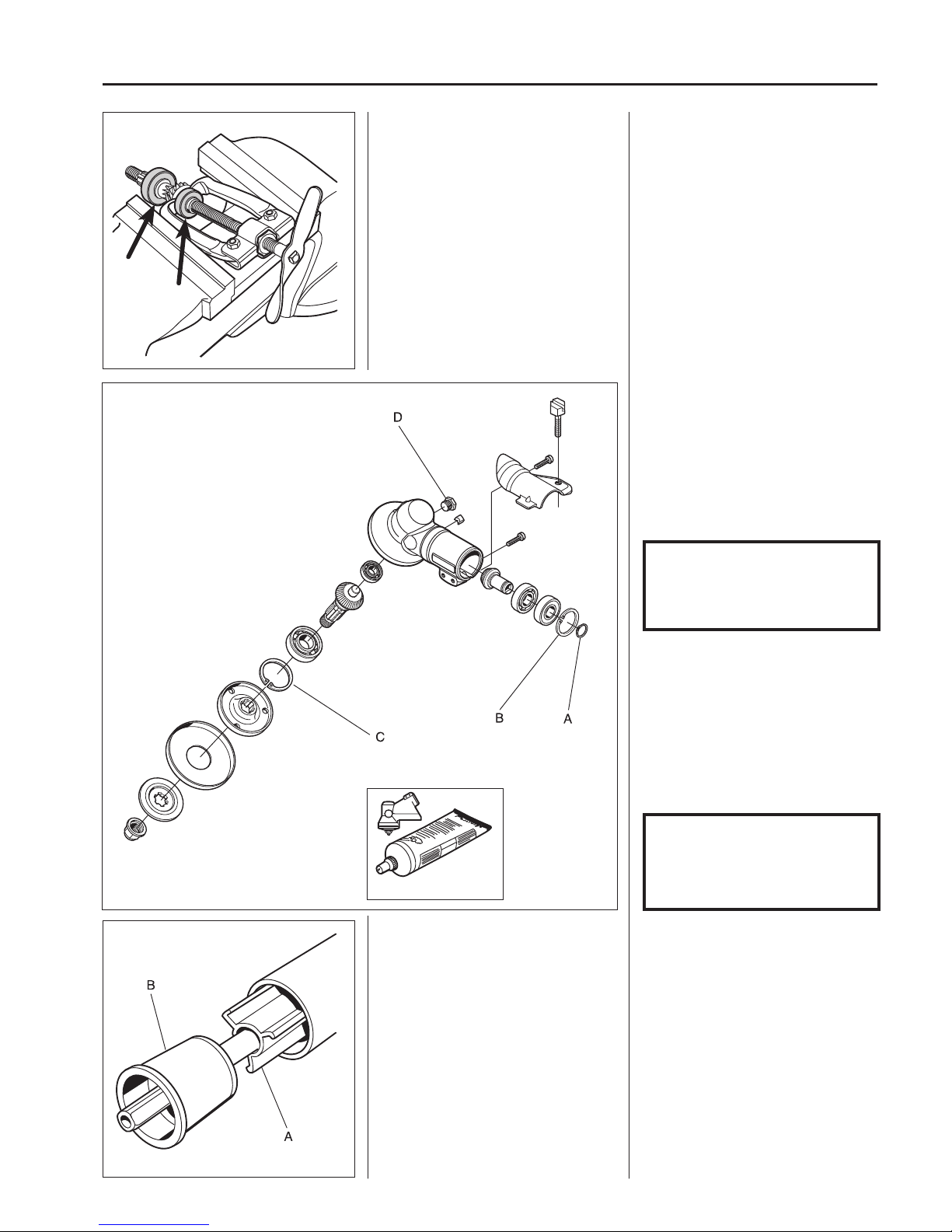
Remove the circlips holding the bearings
on the input respective output shafts.
Heat the entire angle gear to approx.
110°C and rst dismantle the input axle
and then the output axle.
3. Remove the circlip (D).
4. Remove the large circlip holding the
ball-bearing on the input shaft.
Heat the entire angle gear using a hot
air gun to approx. 110°C.
Knock the gear against a wooden block
so that the input axle and the bearing
fall out.
Now lift out the output axle.
Wear protective gloves.
Dismantling
Remove the angle gear from the shaft.
Page 44
43
5
Angle gear
503 97 64-01
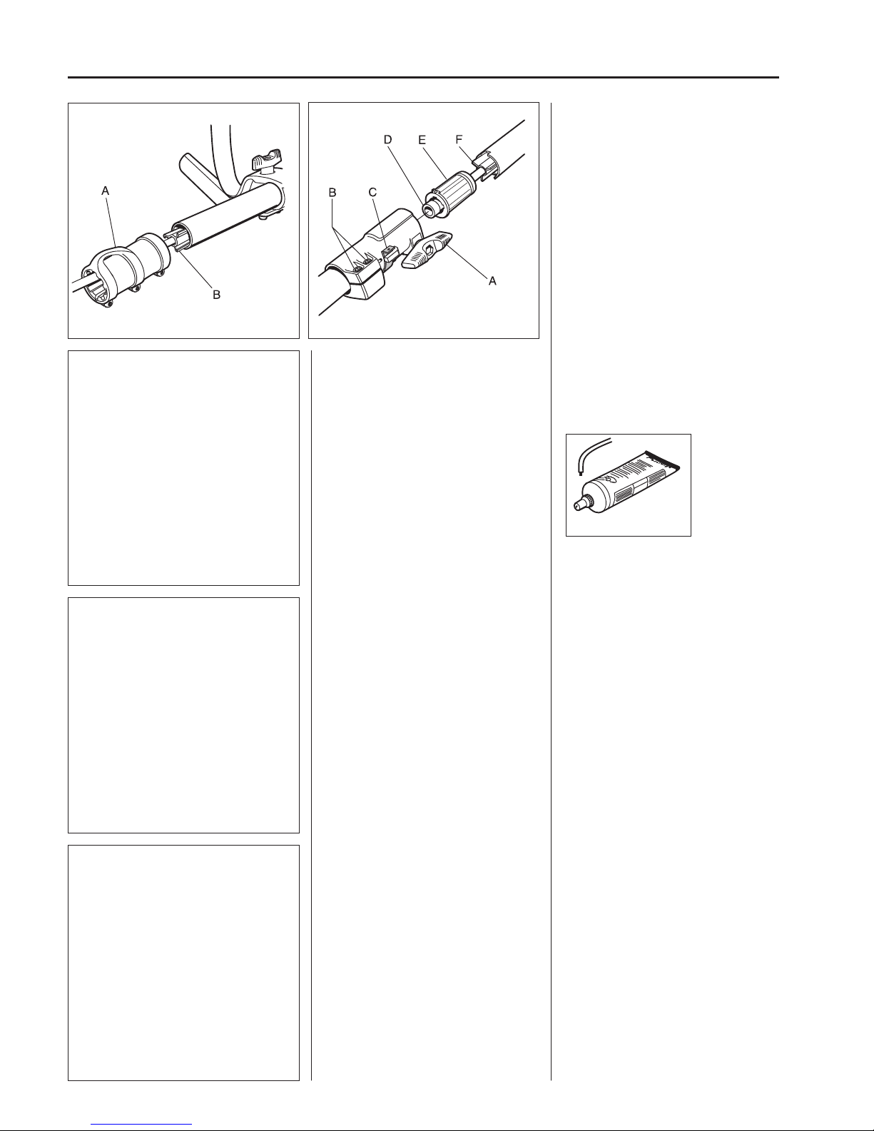
Drive axle
Dismantling
Dismantle the sleeve (B), the drive axle
and guide (A) to check for wear and
possible replacement.
Drive axle
Dismantling
The drive axle can be easily pulled out
of the shaft for inspection or replacement.
The axle is guided with the help of a star
shaped, long guide (A).
Dismantle the sleeve (B) with the help of
a screwdriver or knife.
The guide (A) can now be pulled out of
the shaft for possible replacement.
NOTE!
Do not forget to ll the gear
housing to approx. 3/4 with gear
housing grease 503 97 64-01 once
the plug (D) has been removed.
Assembly
Clean all component parts and replace
if damaged or worn.
Fit the bearings on respective axles.
This is easier if the bearings are heated
to approx. 110°C using a hot air gun.
The bearings on the input axle are
sealed on one side. Turn the bearings
so this side faces outwards.
Heat the gearbox to approx. 110°C and
rst place the output axle in position and
then the input axle.
Make sure the bearing bottoms in its
seating.
Fit the circlips (B) and (C). Make sure
they lie correctly in their grooves.
Assemble remaining parts in the reverse
order as set out for dismantling.
NOTE!
Do not forget the circlip (A)
holding the bearing on the input
axle.
Dismantle the bearings from the output
and input axles.
Dismantle the bearings from the output
and input axles with the help of a small
bearing puller.
TIP!
Hold the bearing puller in a vice so that
it gains a better grip around the bearing.
Page 45
44
5
Angle gear
503 80 17-01
336333/335
(model L och RJ)
Model 333/335
On models with a two-piece shaft, the
guide becomes accessible once the
shaft has been split (see chapter 3).
Dismantle the sleeve (A) and pull out
the guide (B) by pulling the drive axle.
Model 336
Loosen the turn handle (A) and both
screws (B). Press down the locking
spring (C) and seperate the shaft.
Pull out the drive axle (D) and remove
the sleeve (E) with the help of a screwdriver. This makes the guide for the
drive axle (F) accessible if it must be
replaced.
Assembling
Lubricate the drive axle with grease no.
503 80 17-01 when assembling in the
guide.
Page 46

45
6
Cylinder and piston
6
Contents
Dismantling ____________________________________ 46
Cleaning, inspection ______________________________ 47
Analysis and actions ______________________________ 47
Service tips _____________________________________ 52
Wear tolerances _________________________________ 52
Assembly_______________________________________ 53
Cylinder and piston
Page 47
46
6
Cylinder and piston
502 50 18-01
502 52 42-01
505 38 13-08
The cylinder and the piston are two of the components exposed to most strain in the engine. They must
withstand, for example, high speeds, large temperature swings and high pressure. Moreover, they must be
resistant to wear. Despite these tough working conditions, major piston and cylinder failure is relatively
uncommon. The reasons for this include new coatings in the cylinder bore, new types of oil and grease and
re ned manufacturing techniques.
When servicing these components, cleanliness is of the utmost importance. It is therefore recommended
that the cylinder and the area around it be thoroughly cleaned before being dismantled from the crankcase.
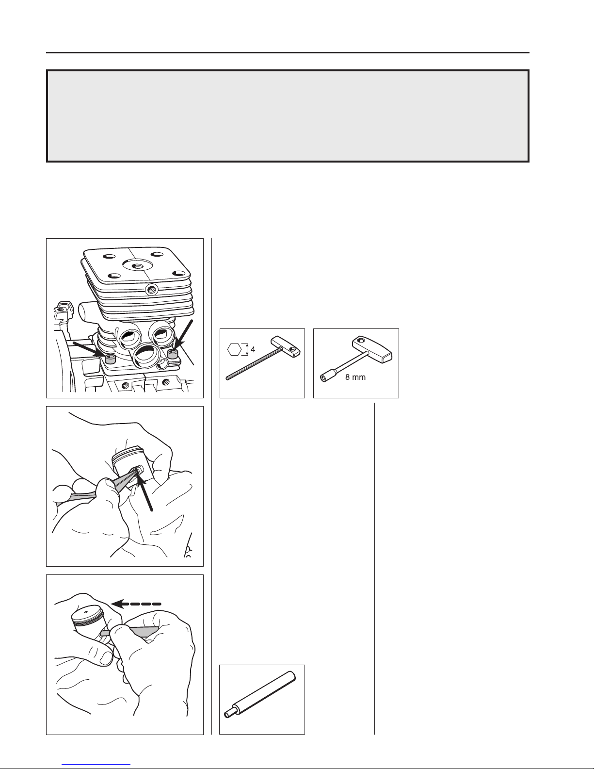
Dismantling
Dismantle the following components to make the cylinder accessible:
Starter, cylinder cover, mu er grille, mu er with heat guard plate, decompression
valve and spark plug.
Dismantle the air lter, carburettor and heat guard/distance piece (see chapter ”Fuel
system”).
Then loosen the 4 bolts holding the cylinder.
Carefully remove the cylinder
straight up by rocking it backwards and forwards. Make sure
that no dirt enters the crankcase.
Use a rag to cover the crankcase
opening under the
piston.
Remove the circlips from the gudgeon
pin.
Using long-nose pliers remove the gudgeon pin circlips.
Keep your thumb over the circlip to prevent it from ying out.
Dismantle the piston.
Push the gudgeon pin from the piston
using punch 502 52 42-01.
If the pin is too tight, carefully warm the
piston.
Page 48
47
6
Cylinder and piston
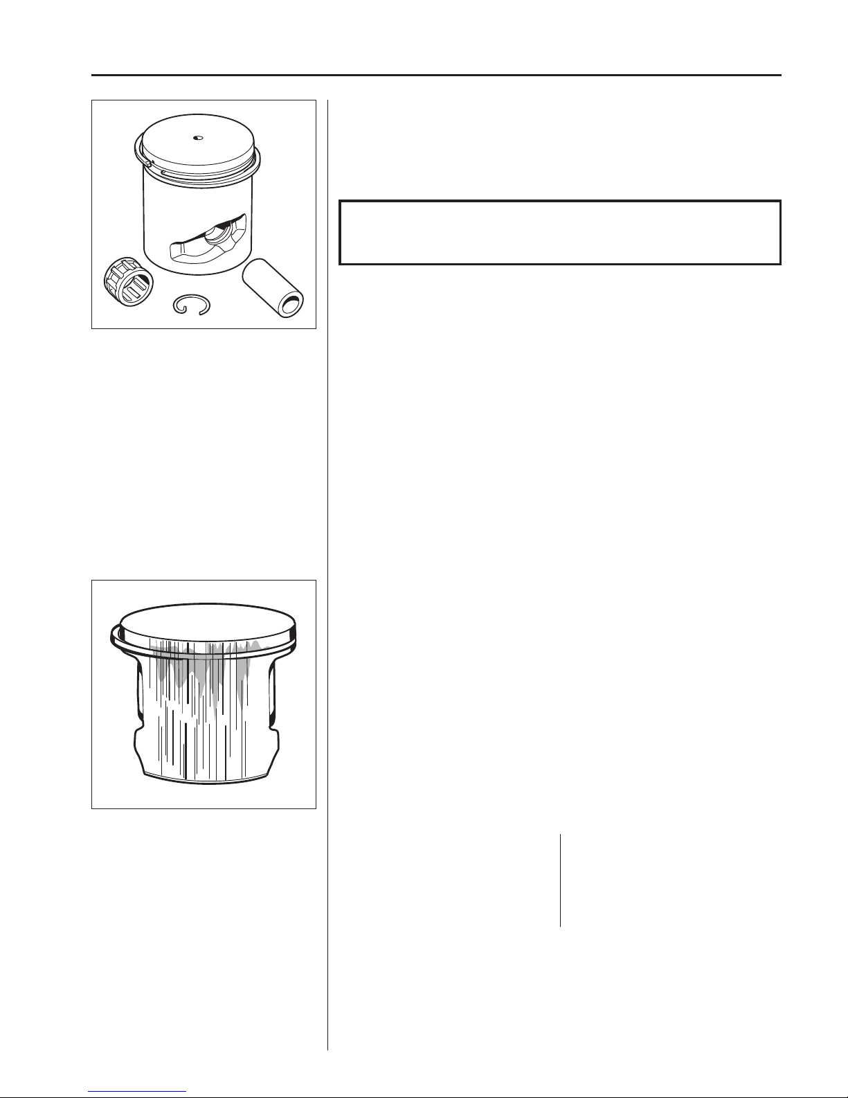
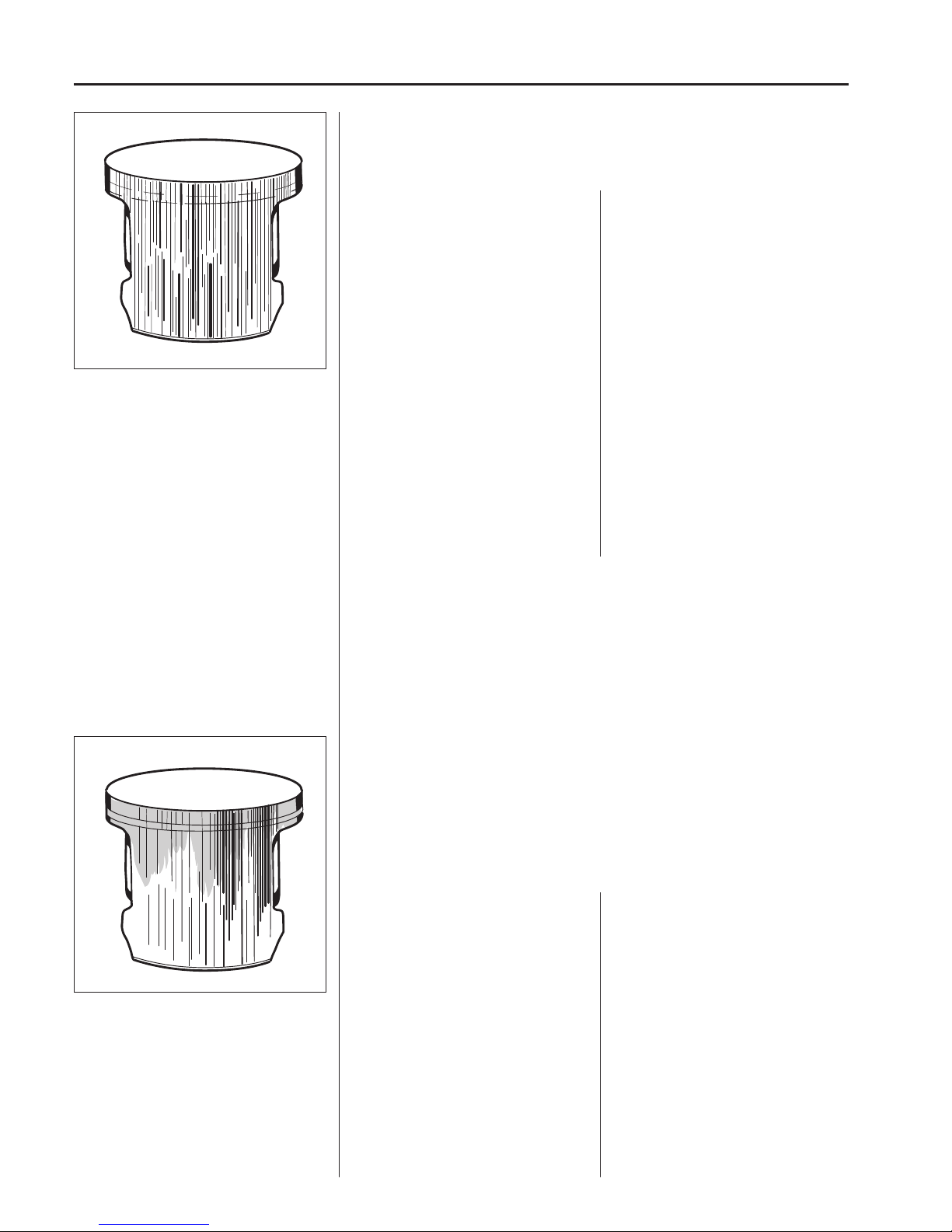
Small to medium size scores primarily in the
middle of the exhaust port.
Cause:
• Incorrect carburettor setting. Recommended max. speed exceeded.
• Incorrect oil mixture in the fuel.
• Too low octane fuel.
Insu cient lubrication
The piston has small to medium size score marks usually in front of the exhaust port.
In extreme cases heat development can be so great that material from the piston
smears along the piston skirt and even in the cylinder bore.
Generally the piston ring is undamaged and moves freely in the ring groove
There can also be scores on the inlet side of the piston.
Analysis and actions
Experience tells us that piston or cylinder failure due to manufacturing errors are
extremely rare.
The reason is usually due to other factors, which is evident from the following.
Note the reasons for the breakdown, repair the damage and take the actions required
to prevent the same thing happening again.
Cleaning, inspection
After dismantling, clean the individual components:
1. Scrape carbon deposits from the top of the piston.
2. Scrape carbon deposits from the cylinder’s combustion chamber.
3. Scrape carbon deposits from the cylinder’s exhaust port.
4. Wash all the components.
5. Inspect the di erent components for damage and wear.
Check the piston and cylinder for seizure damage and wear.
Also see the “Analysis and actions” section.
Check the piston ring for wear and damage.
Also see the “Analysis and actions” section.
Check the gudgeon pin.
– If it has blued, it must be replaced.
– If the piston moves too easily both the piston and the gudgeon pin must be replaced.
Check the needle bearing. If it is discoloured or damaged, it must be replaced.
Check the circlips. If they exhibit cracks or are discoloured (caused by overheating),
they must be replaced.
NOTE!
Scrape carefully with not too sharp a tool so as not to damage the soft
aluminium parts.
Action:
Check and change the carburettor setting.
Change the fuel.
Change the fuel.
Page 49
48
6
Cylinder and piston
Cause:
• Incorrect oil mixture in the fuel.
• Too low octane fuel.
• Air leaks.
Cracked fuel hose.
Leaking inlet gaskets.
Cracked distance piece or inlet
manifold.
• Air leakage in engine body.
Leaking crankshaft seals.
Leaking cylinder and crankcase
gaskets.
• Poor maintenance.
Dirty cooling ns on the cylinder.
Blocked air intake on the starter.
Blocked spark arrestor mesh in
the mu er.
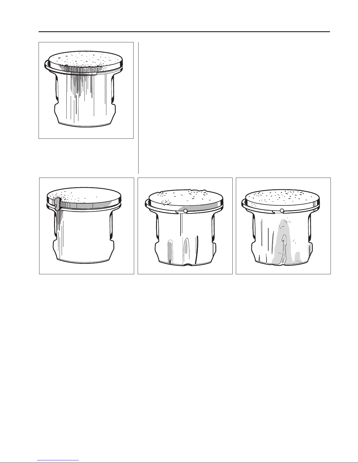
Medium to deep scores along the entire piston
skirt on the exhaust side.
For the best results we recommend Husqvarna two-stroke oil or ready-mixed fuel that
is specially developed for air-cooled two-stroke engines.
Mixing ratio: 1:50 (2%).
If Husqvarna two-stroke oil is not available another good quality two-stroke oil can be
used.
Mixing ratio: 1:33 (3%) or 1:25 (4%).
The piston ring starts to stick or is completely stuck in its groove and has therefore
not been able to seal against the cylinder wall, which has resulted in further, intensive
temperature increases in the piston
Seizure scores along the entire piston skirt on the inlet and exhaust sides.
Medium to deep scores on the exhaust side.
The piston ring is stuck in the groove.
Black discoloration under the piston ring due to
blow-by.
Cause:
• Wrong type of two-stroke oil or petrol.
• Incorrect oil mixture in the petrol.
• Incorrect carburettor setting.
Piston scoring caused by heavy carbon deposits
Too heavy carbon depositing can cause damage similar to that caused by insu cient
lubrication. However, the piston skirt has a darker colour caused by the hot combustion gases that are blown past the piston.
This type of piston damage starts at the exhaust port where carbon deposits can
become loose and get trapped between the piston and the cylinder wall.
Typical for this type of piston damage is brown or black discoloration of the piston
skirt.
Action:
Change to a fuel with the correct oil
mixture.
Change to a higher octane petrol.
Replace damaged parts.
Replace leaking gaskets and shaft
seals.
Clean the cooling ns and air intake.
Clean or replace the spark arrestor
mesh.
Action:
Change the fuel.
Change to a fuel with the correct oil
mixture.
Correct the carburettor setting
Page 50
49
6
Cylinder and piston
Exhaust side damaged by a broken piston ring.
The piston ring parts damage the top section
and cause score marks.
Piston damage caused by a too high engine speed.
Typical damage associated with a too high engine speed includes broken piston
rings, broken circlip on the gudgeon pin, faulty bearings or that the guide pin for the
piston ring has become loose.
Piston ring breakage
A too “lean” carburettor setting results in a too high speed and a high piston temperature. If the piston temperature rises above the normal working temperature the piston
ring can seize in its groove, consequently it will not sit deep enough in its groove.
The edges of the piston ring can then hit the top edge of the exhaust port and be
smashed and also cause piston damage.
A too high engine speed can also cause rapid wear to the piston ring and play in the
piston ring groove primarily in front of the exhaust port. The ring is weakened by the
wear and can be caught in the port causing serious piston damage.
The guide pin for the piston ring has been
pushed up through the top of piston.
Irregular grooves on the piston’s inlet side
caused by a broken roller retainer.
Deep, irregular grooves caused by a loose
circlip. Shown here on the piston’s inlet side.
Piston ring guide pin
vibrated loose
A too high engine speed can cause the
ends of the piston ring to hammer against
the guide pin when the piston ring moves
in its groove. The intensive hammering
can drive out the pin through the top of the
piston causing serious damage also to the
cylinder.
Damage caused by
gudgeon pin circlips
A too high engine speed can cause
the gudgeon pin circlips to vibrate. The
circlips are drawn out of their grooves due
to the vibrations, which in turn reduces
the circlips’ tensioning power. The rings
can then become loose and damage the
piston.
Bearing failure
Failure of the crankshaft bearing or on the
connecting rod bearing is usually caused
by a too high engine speed, resulting in the
bearing being overloaded or overheating.
This in turn can cause the bearing rollers
or ball to glide instead of rotate, which can
cause the roller or ball retainer to break.
The broken debris can be trapped between
the piston and cylinder wall, damaging the
piston skirt.
Debris can also pass up through the
cylinder’s transfer channels and cause
damage to the top and sides of the piston
as well as to the cylinder’s combustion
chamber.
Page 51
50
6
Cylinder and piston
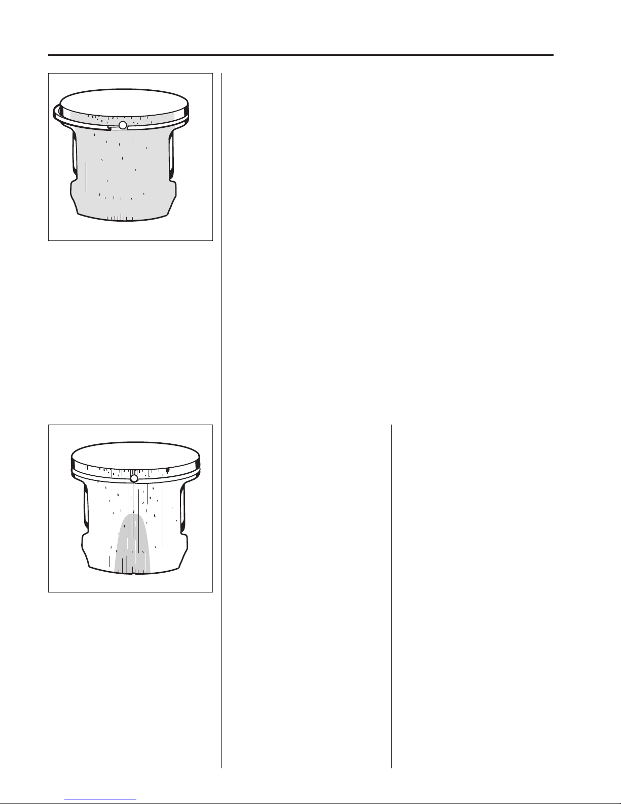
Small score marks and a matt, grey surface
on the piston’s inlet side caused by ne dust
particles.
Cause:
• Faulty air lter. Small dust particles
pass through the lter.
• The lter is worn out due to too
much cleaning, whereby small holes
have appeared in the material.
• Unsuitable lter maintenance, such
as wrong method or wrong cleaning
agent. Flock material becomes loose
and holes appear.
• Air lter incorrectly tted.
• Air lter damaged or missing.
Inlet side.
Particles of dust and dirt from carbon-like
deposits on the top of the piston and in the
piston ring groove. The piston ring sits rmly
in the groove. Piston material has been worn
away.
The lower part of the piston skirt is thinner on
the inlet side than on the exhaust side.
Foreign objects
Everything other than clean air and pure fuel that enters the engine’s inlet port causes some type of abnormal wear or damage to the cylinder and piston.
This type of increased wear shows on the piston’s inlet side starting at the lower
edge of the piston skirt.
The damage is caused by badly ltered air that passes through the carburettor and
into the engine.
Action:
Fit a ner grade lter.
Check the lter carefully for holes and
damage after cleaning. Replace the
lter if necessary.
Clean more carefully and use the right
cleaning agent (such as tepid soapy
water).
Change the lter.
Fit the lter correctly.
Fit a new air lter.
Page 52
51
6
Cylinder and piston
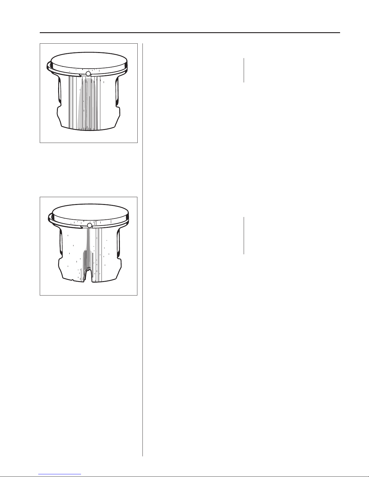
Larger, softer particles that penetrate into the engine cause damage to the piston
skirt under the piston ring as the illustration shows.
Cause:
• Air lter incorrectly tted.
• Air lter damaged or missing.
Action:
Fit the air lter correctly.
Fit a new air lter.
The piston scored and worn from the piston ring
down on the inlet side.
Cause:
• Air lter damaged or missing.
• Parts from the carburettor or intake
system have come loose and entered the engine.
Extensive damage to the lower part of the
piston’s inlet side.
Larger, harder particles that enter the engine cause serious damage to the underside of the piston skirt.
Action:
Fit a new air lter.
Regular service and inspection.
Page 53
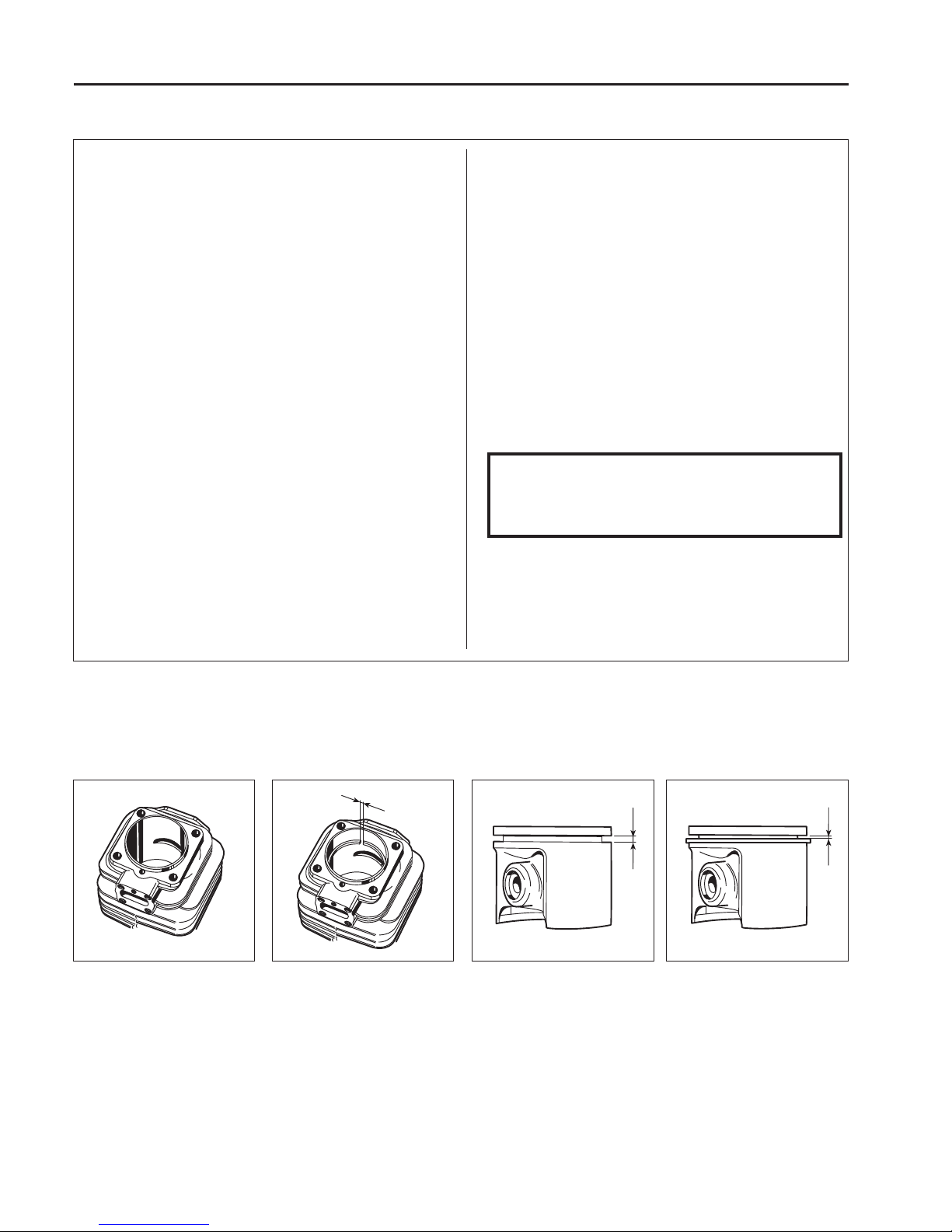
52
6
Cylinder and piston
When the surface coating is
worn and aluminium appears.
Max. 1.0 mm with the piston
ring inserted in the lower part of
the cylinder.
Max. 1.6 mm. Clean the groove
before checking the measurement.
Max. 0.15 mm. Clean the groove
before checking the measurement.
Service tips
Defect:
Broken cooling ns, damaged threads or sheared bolts by
the exhaust port.
Seizure marks in the cylinder bore (especially by the exhaust port).
Surface coating in the cylinder bore worn out (primarily at
the top of the cylinder).
The piston shows signs of seizure score marks.
Piston ring burnt in its groove.
Bolts much too tight in the aluminium material.
Action:
In severe cases – replace the cylinder.
Repair the threads using Heli-Coil.
Polish the damaged area using a ne grade emery cloth so
that the coating of aluminium disappears.
With deep seizure score marks the piston and cylinder
should be replaced.
Replace the cylinder and piston.
Carefully polish the damaged area using a ne le of ne
grade emery cloth. Before the piston is re tted the cylinder
should be polished as above. With deep score marks the
piston and cylinder should be replaced.
Carefully loosen the piston rings and clean the groove well
before re tting. Carbon deposits in the groove impair the
important heat transfer between the piston and cylinder.
NOTE!
Be careful with the lower edge of the piston ring
groove. If this is damaged, or if carbon deposits
remain, the compression pressure can leak through.
Check the wear on the piston ring by placing it in the lower
part of the cylinder.
Position a suitable punch on the bolt head and give a few
sharp knocks with a hammer. If the bolt still does not loosen,
repeat the procedure.
Wear tolerances
Piston ring playPiston ring groovePiston ring gap
Cylinder bore
Page 54
53
6
Cylinder and piston
502 50 70-01
Lubricate the seal (A) using silicone
spray or washing-up liquid and press
it into the cylinder connections. Pay
attention to the connection for the pulse
channel.
NOTE!
Do not turn the cylinder, as the piston rings can easily be broken.
Tighten the 4 screws diagonally crosswise.
NOTE!
Use silicone glue on the
connections for the manifold on
the heat shield.
Assemble the remaining parts in the
reverse order as set out for dismantling.
See respective sections in the manual.
NOTE!
Do not lubricate the rubber
connection with oil as this can
cause the rubber to swell.
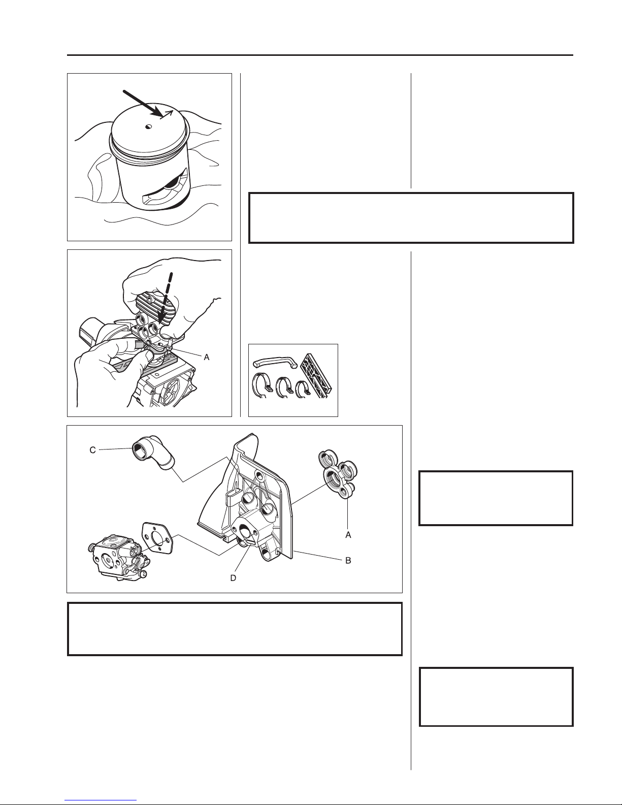
Assembly
Clean the crankcase.
Assemble the piston on the connecting
rod.
Assembly
Clean the crankcase.
Fit the piston on the connecting rod
so that the arrow on the piston points
towards the exhaust port. Lubricate the
gudgeon pin’s needle bearing with a few
drops of engine oil.
Direct the arrow on the top of the piston
towards the exhaust port. Press in the
gudgeon pin and t the circlips.
NOTE!
Place a rag in the crankcase opening to prevent the circlip from falling into
the crankcase in case it should y out. Check that the circlips are correctly
tted into the grooves by turning the clips with at nosed pliers.
Check that the pulse channel (A) in the
cylinder is open.
Assemble the cylinder with the help of
assembly set 502 50 70-01.
Check that the pulse channel (A) in the
cylinder is open.
Place a new cylinder base gasket on
the crankcase. Lubricate the piston and
the big-end bearing with a few drops of
engine oil.
Assemble the cylinder with the help of
the piston ring compressor in the assembly set 502 50 70-01.
Check that the ”distance piece/heat
shield (B) is not cracked or shows signs
of other damage that can cause leakage
from the carburettor connection. Also
check that the impulse channel (D) is
fully open. Lubricate the connections to
the rubber seal using silicone spray or
washing-up liquid and t the shield.
Check that the manifold (C) for additional air is not cracked or perforated,
which can result in leakage. Fit the
manifold.
Page 55
54
6
Cylinder and piston
A
B
D
C
E
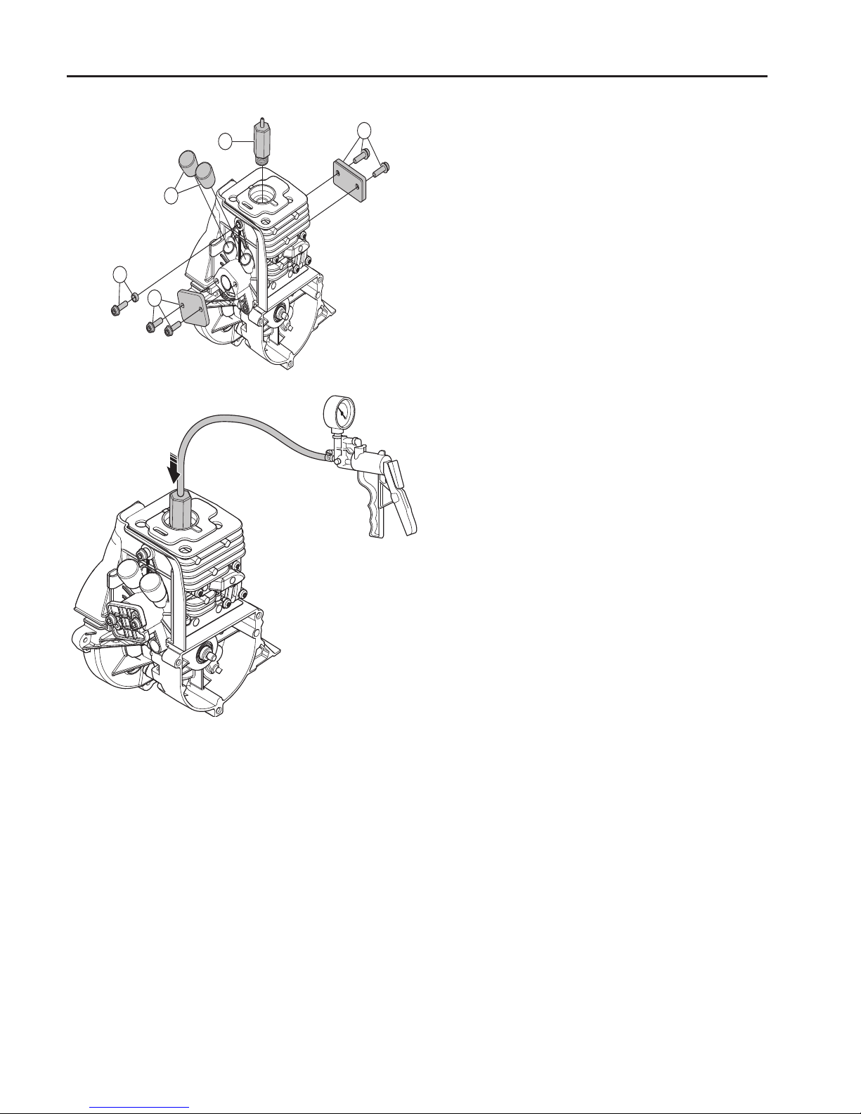
Do a test of the gaskets of the crankcase
and cylinder
1. Assemble the distance piece/heat
shield with 1 screw (A).
2. Attach the seal intake with 2 screws
(B).
3. Attach the sealing plugs (C) to the
distance piece/heat shield.
4. Attach the grommet with 2 screws
(D).
5. Attach the pressure testing tool (E).
6. Connect pressure tester to
the pressure testing tool.
7. Test the pressure at 60 kPa..
In the event of leakage – Lokate the leakage with leakage spray. Replace broken
parts.
Page 56
55
7
Crankshaft and crankcase
7
7
Contents
Dismantling ____________________________________ 56
Inspecting the crankshaft _________________________ 58
Assembly ______________________________________ 59
Crankshaft and crankcase
Page 57
56
7
Crankshaft and crankcase
502 50 18-01
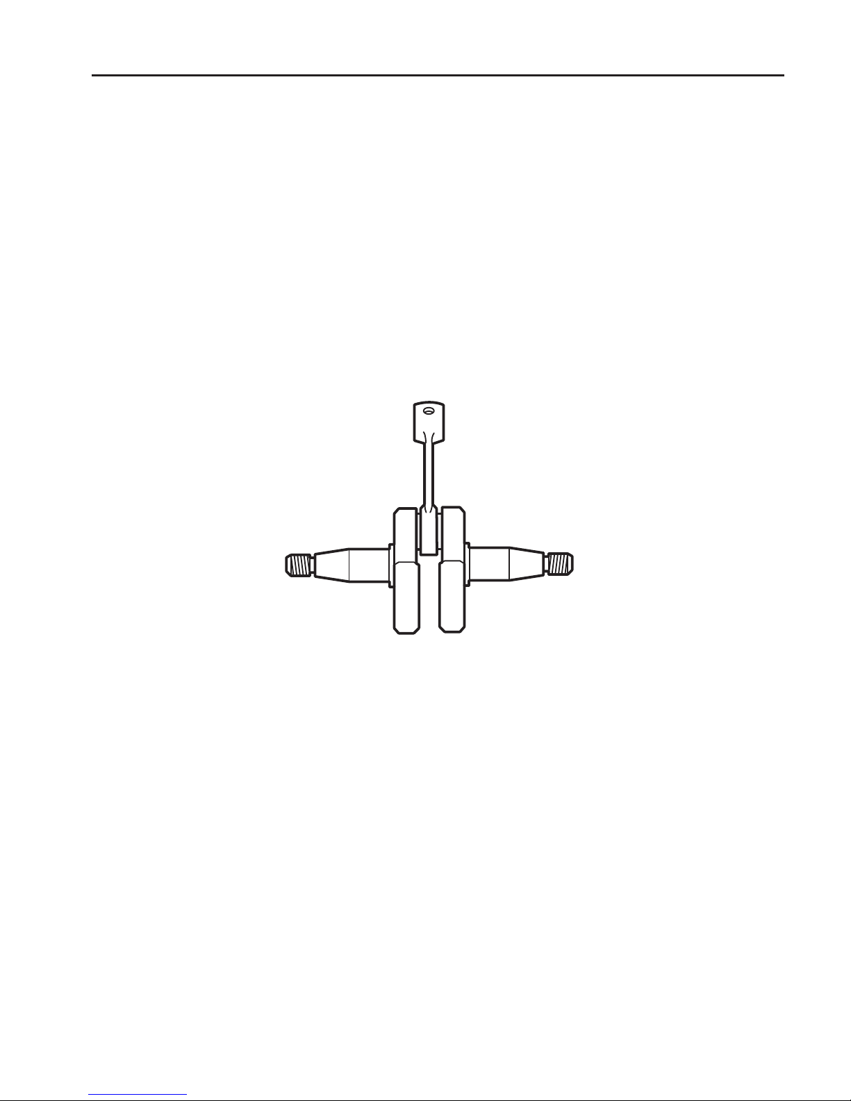
The task of the crankshaft is to transform the reciprocating motion of the piston to rotation. This requires a
stable design withstanding immense pressure and rotational and bending strain, as well as high rotational
speed. In addition the connecting rod is exposed to large acceleration and retardation forces as it moves between the top and bottom dead centres. This puts special demands on the bearings that must withstand quick
changes in load. Moreover, the bearing’s roller retainer must also cope with high temperatures and friction. It
is therefore extremely important when servicing to check the roller retainer for cracks, wear and discolouration caused by overheating.
The crankshaft is journalled in the crankcase on heavy-duty ball bearings. In addition to the journalling
point for the crankshaft, the crankcase acts as a scavenging pump for the fuel/air mixture when this is
“sucked” from the carburettor and is forced into the cylinder’s combustion chamber. The crankcase must
be perfectly sealed so as not to a ect this pump function. There cannot be any leakage from the crankshaft,
between the crankcase halves or between the crankcase and the cylinder.
Always replace the sealing rings and gaskets when servicing the crankcase.
Dismantling
Dismantle all components so that only
the crankcase and crankshaft remain.
Dismantling
Dismantle all components so that only
the crankcase and crankshaft remain.
See the respective sections for detailed
information if necessary.
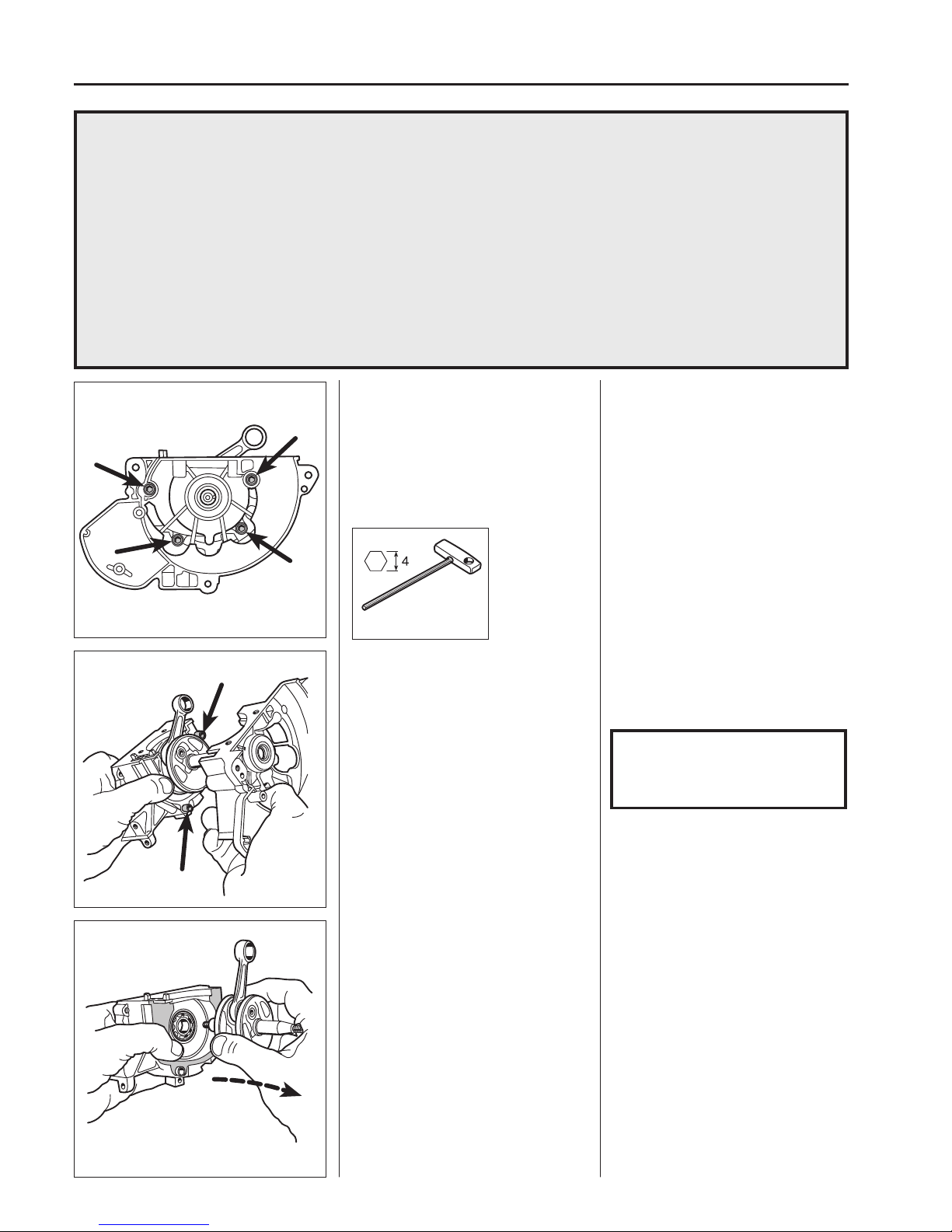
Dismantle the 4 screws holding the
crankcase halves together.
Separate the crankcase halves.
Separate the crankcase halves (a special tool is not required).
The crankshaft has a snug t in the
crankshaft bearing.
NOTE!
Note the guide sleeves between
the crankcase halves so they are
not lost!
Lift out the crankshaft.
Remove the crankcase gasket.
Lift out the crankshaft out of the clutch
side’s crankcase half (a special tool is
not required).
Remove the crankcase gasket.
Page 58
57
7
Crankshaft and crankcase
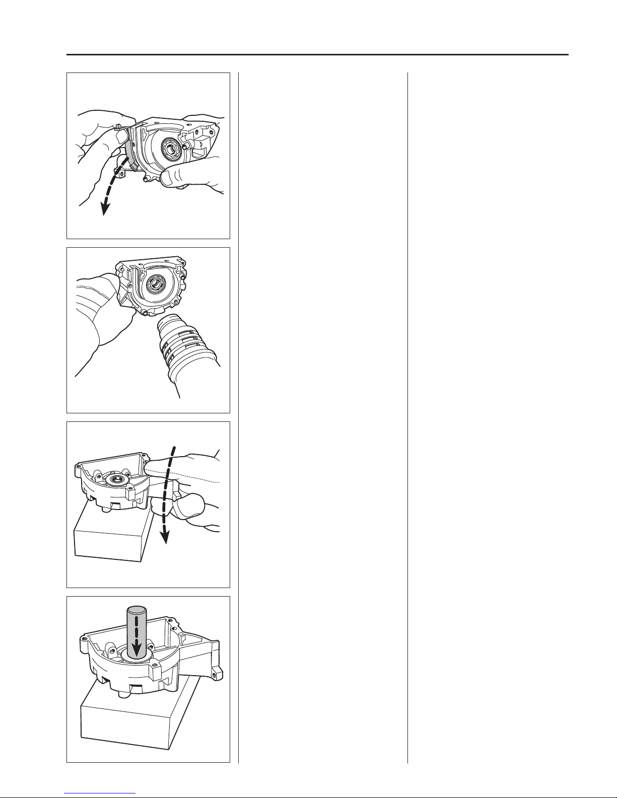
Lift o the plastic piece that separates
the wide ush channel in the crankcase.
Lift o the plastic piece that separates
the wide ush channel in the crankcase.
Dismantle the ball-bearings from the
crankcase halves.
Dismantle the ball-bearings from the
crankcase halves.
Heat the crankcase halves to 110°C
using a hot air gun.
Dismantle the sealing rings from the
crankcase halves.
Dismantle the sealing rings from the
crankcase halves.
Use a suitable punch or sleeve and
knock out the sealing rings with the help
of a hammer. Do this while the crankcase half is still warm if possible.
Now clean the crankcase halves and
crankshaft.
Knock the crankcase half against a
wooden block so that the ball-bearing
falls out.
Knock the crankcase half against a
wooden block so that the ball-bearing
falls out.
Page 59
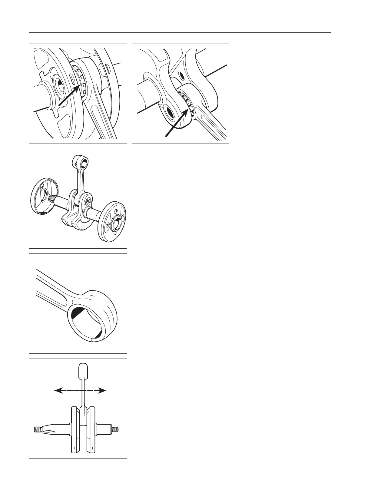
58
7
Crankshaft and crankcase
333/335 336
333/335
Check that there is no play in the cups
around the crank disks.
Check that there is no play in the cups
around the crank disks.
Inspecting the
crankshaft
The crankshaft cannot be reconditioned
but must be replaced if it is worn or
damaged.
Inspect the large end of the connecting
rod. If seizure marks, discolouration on
the sides or damaged needle holders
are found the crankshaft must be replaced.
Inspect the small end of the connecting
rod.
Inspect the small end of the connecting
rod.
If seizure marks or discolouration are
found in the bearing track the crankshaft
must be replaced.
Check the crank bearing. Check the crank bearing. The
connecting rod shall not have any radial
play (up and down).
It should, however, have axial play, in
order to ensure good lubrication of the
crank bearing among other things.
Page 60
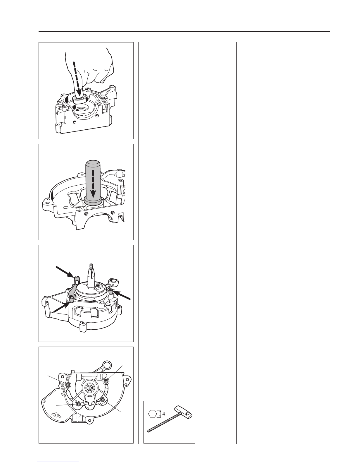
59
7
Crankshaft and crankcase
502 50 18-01
1
2
3
4
Assembly
Mount the bearings in the crankcase
halves.
Assembly
Mount the bearings in the crankcase
halves.
Heat the crankcase halves to approx.
110°C using a hot air gun. Put the ballbearings in position.
Use a suitable punch and hammer, if
needed.
Fit the sealing rings in the crankcase
halves.
Fit the sealing rings in the crankcase
halves with the help of a suitable punch.
Turn the sealing rings so the metal collar
faces outwards.
Fit the crankshaft, guide sleeves and
guide rail in the clutch side’s crankcase
half.
Fit the crankshaft in the clutch side’s
crankcase half. Lubricate the stub axle
with a few drops of oil and carefully slide
in the crankshaft in the ball-bearing so
that the sealing ring is not damaged by
the shoulder on the stub axle.
Place the guide rail in position in the
ush channel.
Place the 2 guide sleeves in the crankcase half.
Place a new crankcase gasket in position.
Fit the ywheel side’s crankcase half.
Tighten the 4 crankcase screws crosswise.
Place a new crankcase gasket on the
crankcase and secure if necessary with
a little grease.
Lubricate the tapered crankshaft journal
with a few drops of oil and slide the ywheel side’s crankcase half in position.
Tighten the 4 crankcase screws crosswise.
Check that the crankshaft can rotate
easily.
Page 61
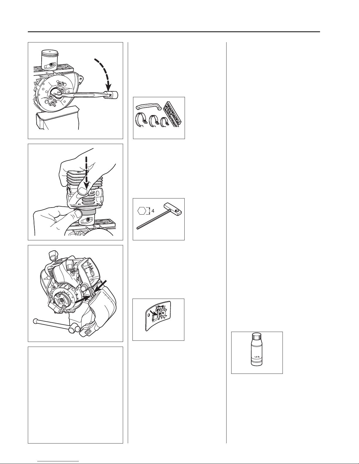
60
7
Crankshaft and crankcase
502 50 18-01
502 50 70-01
502 51 34-02
0.3
531 00 60-76
Assemble the piston.
Attach the ywheel.
Assemble the piston on the connecting
rod.
Check that the piston is turned so the
arrow points towards the exhaust port.
Make sure that the gudgeon pin circlips
are seated correctly in the slots.
Attach the ywheel.
Assemble the cylinder.
Assemble the cylinder.
Position the cylinder base gasket.
Lubricate the piston and piston rings
with a few drops of oil.
Use the piston ring compressor and
carefully slide the cylinder into position.
Tighten the four screws, crosswise.
Assemble the remaining parts in the
reverse order as set out for dismantling.
See relevant sections in the manual.
Full engine assembly sequence
1. Crankshaft with attached piston in
the crankcase.
2. Flywheel on the crankshaft.
3. Drive cup on the crankshaft.
4. Centrifugal clutch on the ywheel.
5. Cylinder.
6. Ignition module, air gap adjustment.
7. Carburettor distancer/heat shield
against the cylinder. Lubricate the
connections with oil. Tighten the two
lower screws.
8. Mu er with gasket.
9. Carburettor complete with air lter
holder and tted pressure rods, connected fuel hoses and attached fuel
tank (Also refer to the “Fuel system”
chapter).
10. Fit the clutch cover and check that
the rubber sleeves are correctly t to
the fuel tank and that the ignition cable is inserted in the cable channel.
11. Put the cylinder cover in place.
12. Starter. Do not lose the rubber bushings tted between the starter and
the fuel tank.
Make sure the fuel hoses are
pressed in as far as possible in the
fuel tank to avoid twists in the hoses
to prevent fuel stoppages.
13. The protective cover under the engine, the protective cover above the
mu er, the air lter (oiled), the air
lter cover and the spark plug.
Page 62
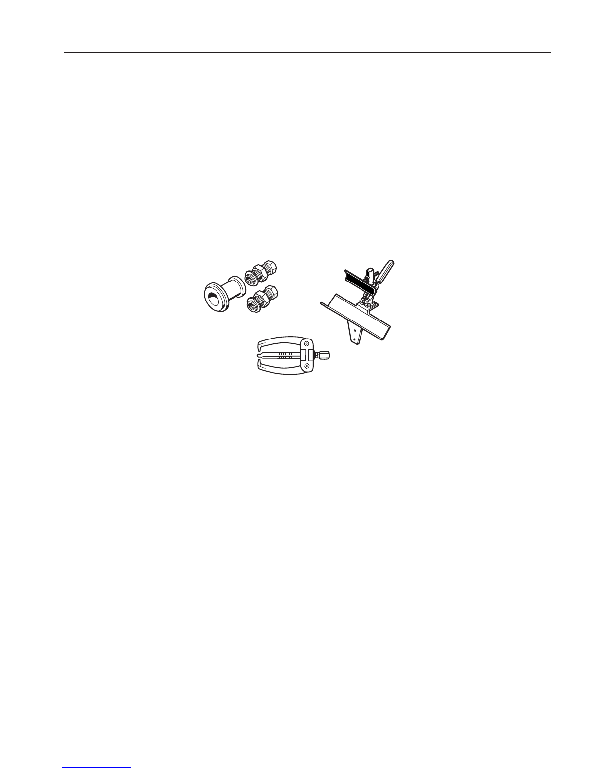
61
8
List of tools
8
Tools
Contents
Starter _______________________________________ 62
Electrical system _______________________________62
Fuel system ___________________________________ 62
Centrifugal clutch ______________________________ 62
Angle gear ___________________________________ 63
Cylinder and piston ____________________________63
Crankshaft and crankcase _______________________63
Workshop equipment __________________________63
Page 63
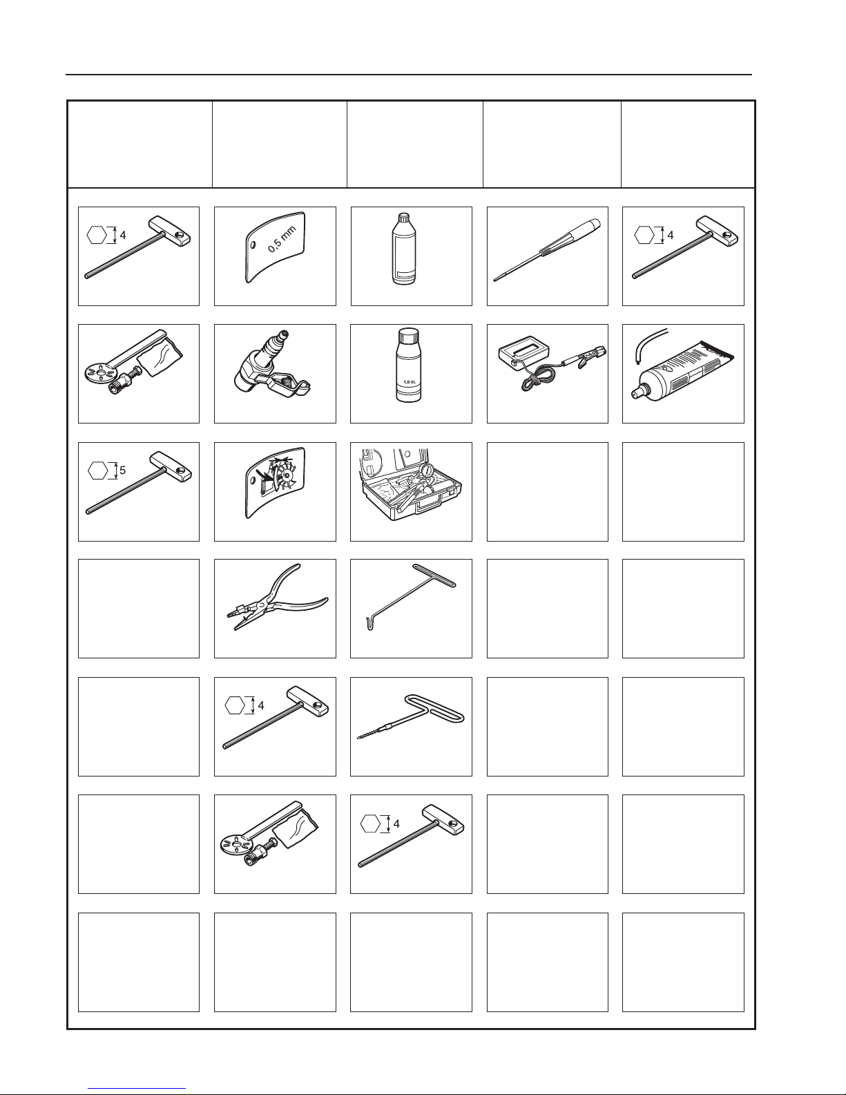
62
8
List of tools
502 51 91-01
502 71 13-01
502 51 34-02
0.3
502 50 06-01
531 00 60-76
502 50 83-01
502 50 18-01
505 69 85-70
502 51 49-01
531 00 48-63
504 62 29-01
531 03 06-23
502 50 18-01
502 51 49-01
502 50 18-01
502 71 14-01
502 50 18-01
503 80 17-01
502 50 64-01
Electrical
system
Centrifugal
clutch
Starter
Fuel system
Fuel system
Page 64
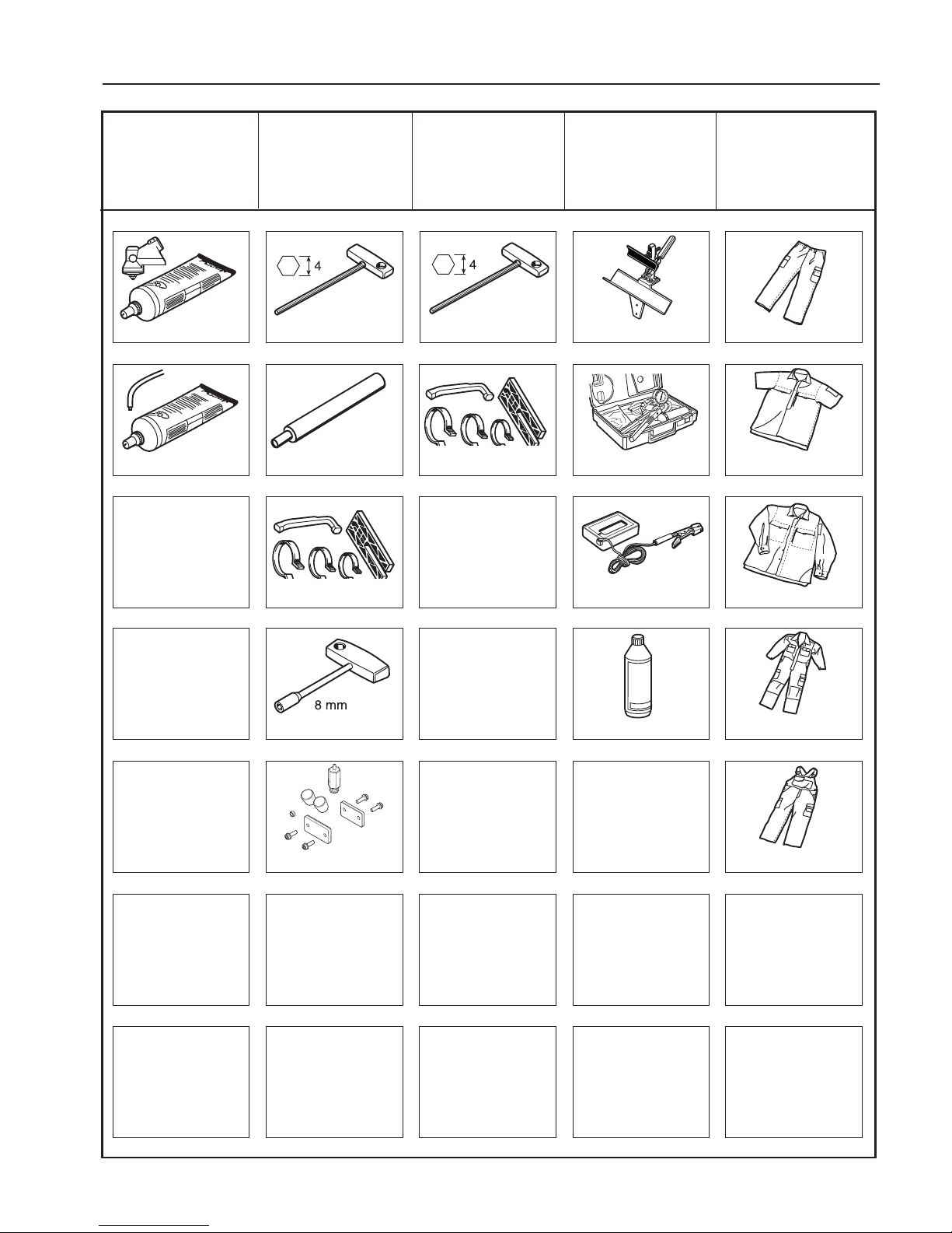
63
8
List of tools
502 51 03-01
502 71 14-01
503 97 64-01
531 03 06-23
502 50 18-01
505 69 85-70
502 52 42-01
503 80 17-01
502 50 70-01
502 50 18-01
502 50 70-01
544 13 05-01
544 13 08-01
544 13 09-01
544 13 10-01
544 34 87-01
505 38 13-08
Angle gear
Cylinder and
piston
Crankshaft and
crankcase
Workshop
equipment
Workshop
equipment
590 67 18-01
Page 65

64
8
List of tools
Page 66
65
9
Technicel data
9
Technical data
Contents
Engine _______________________________________ 66
Ignition system ________________________________66
Carburettor ___________________________________66
Clutch _______________________________________66
Driving ______________________________________66
Dimensions ___________________________________ 66
Page 67

66
9
Technical data
R RJ, RJX RX, RXT FR, FRD LS, LX
135 333, 335 335, 535 335, 336 335, 335
333 535 535 336
Engine
Displacement, cm3 34.6 34.6 34.6 34.6 34.6
Cylinder bore, mm 38.0 38.0 38.0 38.0 38.0
Stroke, mm 30.5 30.5 30.5 30.5 30.5
Compression ratio 10.5 10.5 10.5 10.5 10.5
Max output, kW / speed, rpm 1.6 / 8400 1.6 / 8400 1.6 / 8400 1.6 / 8400 1.6 / 8400
1.4 (135) 1.4 (336)
Ignition system
Walbro digital, max speed, rpm 11800 11800 11800 11800 11800
Pre-ignition at max output, degrees 28 28 28 28 28
Pre-ignition at idling, degrees 23 23 23 23 23
Spark plug, Champion RCJ6Y RCJ6Y RCJ6Y RCJ6Y RCJ6Y
Carburettor
Manufacturer Zama EL-36D EL-36D EL-36D EL-36D EL-36D
EL-36A (135) EL-36A (336)
Basic setting H-needle, turns 2.0 (135) 2.0 (333, 335) 2.0 (335) 2.0 (335) 1.75
2.0 (333) 2.0 (535) 2.0 (535) 2.0 (336)
Basic setting L-needle, turns 0.75 (135) 1.0 (333, 335) 1.0 (335) 1.0 (335) 1.0
1.0 (333) 1.0 (535) 1.0 (535) 0.75 (336)
Idle speed, rpm 2900 2900 2900 2900 2900
Air lter type Foamed Foamed Foamed Foamed Foamed
plastic plastic plastic plastic
plastic
Throttle control, type Fore nger Fore nger Fore nger Fore nger Fore nger
throttle throttle throttle throttle throttle
Clutch
2-shoe clutch. Diameter, mm 63 63 63 63 63
Engage speed, rpm 3700 3700 3700 3700 3700
Driving
Angle gear, degrees 35 35 35 35 35
Angle gear, gear ratio 1.40 1.29 1.40 1.29 1.29
Control drive disc, inch 1 1 1 1 1
Shaft diameter, mm 28.0 28.0 28.0 28.0 28.0
Drive axle diameter, mm 8 / 5.4 8 / 5.4 8 / 5.4 8 / 5.4 8 / 5.4
Drive axle connections,
4-square / 4-square Yes Yes Yes Yes Yes
Dimensions
Weight, kg 6.8 (135 R) 5.9 (333 RJ) 6.2 (335 RX) 6.2 (335 FR) 5.4 (335 LS)
6.1 (333 R) 6.0 (335 RJX) 6.2 (535 RX) 7.0 (336 FR) 5.4 (335 LX)
5.9 (535 RJ) 6.1 (535 RXT) 7.4 (336 FRD)
Tank volume, litres 0.6 0.6 0.6 0.6 0.6
Page 68

504 54 34-26
2018W35
 Loading...