

Page 1
2005
HUV4420 and HUV4420-D
Illustrated Parts List
HUV4420 and HUV4420-D
Gasoline and Diesel Vehicles
Manual Number 603001805
Edition Code 0105F1207E
Page 2

Page 3

USING THE ILLUSTRATED PARTS LIST
ý WARNING
• This manual is to be used only for identification and ordering of service parts. Be sure to read
and use the maintenance and service manual before attempting any vehicle repairs.
This manual covers all HUV4420 gasoline and HUV4420-D diesel vehicles.
The manual is divided i nto 15 sections. Sections 1 through 14 pertain to the gasol ine and diesel vehicles,
Section 15 pertains to tools that are used on all Husqvarna products.
Use the Tabl e of Contents to find th e sections and pages that c ontain the parts and assemblies y ou seek.
The Table of Contents lists section numbers, and unde r them, the individua l page titles and numbe rs to be
found in that sec tion. Th e inde x ca n b e used t o find spec ific parts and ass embl ies. Th e ind ex is d ivid ed int o
numerical and alphabetical listings with the page numbers in italic text.
There is a two-page spread for each individual page title in the T able of Contents. On the left-hand page is an
illustration showi ng the parts in their rela tive positions; th e parts are each tagged with an i tem number in a
balloon. The right-hand page is the parts list page, and gives the page title at the top, then the item numbers
(corresponding to the numbers on the illustration), part descriptions, and quantity of parts used.
Note that a part description may be indented. This indention corresponds to a parts assembly level indicated
by the numbers 1, 2, 3, and 4 at the top left corne r of the parts descri ption area of the parts list page. A part
that is indented to level 2 is a component of the level 1 part (assembly) that it is listed under. A level 3 part is
a component of the level 2 part that it is listed u nder, and a level 4 part is a component of the level 3 pa rt
preceding it. In each cas e, the part quantity given for a leve l 2, 3, or 4 part is the quantity used pe r next
higher level assembly of which it is a component. A part that is not indented is a level 1 part. This means that
the quantity given is the quantity used per the portion of the vehicle illustrated on that particular spread.
HOW TO ORDER PARTS
Replacement parts and accessories can be obtained from our network of authorized dealers and distributors.
For the name and address of the Husqvarna representative nearest you, logon to our web site at
www.usa.husqvarna.com. If you would prefer to write to us, direct your letter to: Husqvarna, Attention:
Marketing Services, 7349 Statesville Rd., Charlotte, NC 28269 USA. Your local authorized Husqvarna
representative can also provide technical advice, parts, and service manuals.
Husqvarna Forest and Garden
7349 Statesville Rd.
Charlotte, NC 28269
USA
www.husqvarna.com
Page 4

NOTE: This illustrated parts list represents the most cur rent in formation at the time of publicati on. Husq-
varna is continuall y working to further improve its vehicles and other products. Thes e improvements may affect the parts used to service the vehicle. Any modification and/or significant change
in specificatio ns will be for warded to all Hus qvarn a distr ibuto rs/deal ers and wil l, when applica ble ,
appear in future editions of this illustrated parts list.
Husqvarna reserves the right to change specifications and designs at any time without notice and
without the obligation of making changes to units previously sold.
2005 HUV4420 and HUV4420-D Gasoline and Diesel Vehicles Illustrated Parts List
Page 5

CONTENTS
SECTION 1 – BODY AND TRIM
Front Body Trim, Gasoline Vehicles ................................................................................................. 1-3
Front Body Trim, Diesel Vehicles ..................................................................................................... 1-5
Front Body Components ................................................................................................................... 1-7
Front Seats and Cup Holder ............................................................................................................. 1-9
ROPS ................................................................................................................................................ 1-11
Tilt Bed and Hinge ............................................................................................................................ 1-13
Electric Bed Lift ................................................................................................................................. 1-15
Cargo Box ......................................................................................................................................... 1-17
Rear Body Trim ................................................................................................................................. 1-19
Camouflage Covers .......................................................................................................................... 1-21
SECTION 2 – WHEELS AND TIRES
Wheels and Tires, All-Terrain Tread ................................................................................................. 2-3
Wheels and Tires, Mud Tread .......................................................................................................... 2-5
SECTION 3 – DECALS
Safety Decals, Gasoline Decals ....................................................................................................... 3-3
Safety Decals, Gasoline Vehicles, Continued .................................................................................. 3-5
Safety Decals, Diesel Vehicles ......................................................................................................... 3-7
Safety Decals, Diesel Vehicles, Continued ....................................................................................... 3-9
Badging Decals, HUV 4420 .............................................................................................................. 3-11
SECTION 4 – BRAKE SYSTEMS
Front Brake Assembly ...................................................................................................................... 4-3
Rear Brake Assembly ....................................................................................................................... 4-5
Master Cylinder ................................................................................................................................. 4-7
Hydraulic Brake Lines and Clips ....................................................................................................... 4-9
Park Brake Assembly with Pulley System ........................................................................................ 4-11
Park Brake Assembly with Bellcrank System ................................................................................... 4-13
SECTION 5 – PEDAL GROUP
Accelerator Pedal Assembly ............................................................................................................. 5-3
Brake Pedal Assembly ...................................................................................................................... 5-5
Park Brake Pedal Assembly ............................................................................................................. 5-7
Park Brake Pedal Assembly with Bellcrank System ......................................................................... 5-9
2005 HUV4420 and HUV4420-D Gasoline and Diesel Vehicles Illustrated Parts List Page 1
Page 6

CONTENTS
SECTION 6 – STEERING AND SUSPENSION
Steering Column .............................................................................................................................. 6-3
Steering Gear Assembly .................................................................................................................. 6-5
Front Suspension – A-Arms ............................................................................................................. 6-7
Front Suspension (Standard) ........................................................................................................... 6-9
Front Suspension (High-Capacity Option) ....................................................................................... 6-11
Rear Suspension (Standard) ............................................................................................................ 6-13
Rear Suspension (High-Capacity Option) ........................................................................................ 6-15
SECTION 7 – ELECTRICAL SYSTEM
Wiring – Gasoline Vehicles .............................................................................................................. 7-5
Forward/Reverse Shifter Assembly ... ...... ....... ...... ....... ...... ....... ............................................. ...... ..... 7-7
Wiring – Diesel Vehicles .................................................................................................................. 7-11
Headlights ........................................................................................................................................ 7-13
Electrical Component Box, Gasoline Vehicles ................................................................................. 7-15
Electrical Component Box, Diesel Vehicles ..................................................................................... 7-17
Electrical Components, Instrument Panel, Gasoline Vehicles ......................................................... 7-19
Electrical Components, Instrument Panel, Diesel Vehicles ............................................................. 7-21
Battery – Gasoline Vehicles ............................................................................................................. 7-23
Battery – Diesel Vehicles ................................................................................................................. 7-25
SECTION 8 – DIESEL ENGINE – CLOSED BREATHER
Kubota D722 Diesel Engine Mounting .............................................................................................8-3
Crankcase ............................ ....................................................................... ..................................... 8-5
Oil Pan ............................................................................................................................................. 8-7
Cylinder Head .................................................................................................................................. 8-9
Gear Case ........................................................................................................................................ 8-11
Head Cover ...................................................................................................................................... 8-13
Dipstick and Guide ........................................................................................................................... 8-15
Oil Pump .......................................................................................................................................... 8-17
Main Bearing Case ........................................................................................................................... 8-19
Camshaft and Idle Gear ................................................................................................................... 8-21
Piston and Crankshaft ...................................................................................................................... 8-23
Flywheel ...................................................................... ..................................................................... 8-25
Shaft .............................. .............................................. ..................................................................... 8-27
Idle Apparatus .................................................................................................................................. 8-29
Stop Solenoid ................................................................................................................................... 8-31
40-Amp Alternator .................................................................... ...... ...... ....... ...... ....... ...... .................. 8-33
Page 2 2005 HUV4420 and HUV4420-D Gasoline and Diesel Vehicles Illustrated Parts List
Page 7

CONTENTS
60-Amp Alternator ............................. ....... ...... ....... ...... ............................................. ....... .................. 8-35
Injection Pump .................................................................................................................................. 8-37
Speed Control Plate .......................................................................................................................... 8-39
Nozzle Holders and Glow Plugs ................................. ....... ...... ...... ................................................... 8-41
Governor Components ..................................................................................................................... 8-43
Starter ............................ .......................................................... ......................................................... 8-45
Valves and Rocker Arms .................................................................................................................. 8-47
Diesel Inlet Manifold ......................................................................................................................... 8-49
Exhaust Manifold .............................................................................................................................. 8-51
Gasket Kits ....................................................................................................................................... 8-53
Piston Kit ........................................................................................................................................... 8-55
SECTION 9 – HONDA GX620 GASOLINE ENGINE
Honda GX620 Gasoline Engine Mounting ........................................................................................ 9-3
Shrouds and Brackets ...................................................................................................................... 9-5
Ignition Components and Flywheel ................................................................................................... 9-7
Oil Circulation ................................................................................................................................... 9-9
Cylinder Head ................................................................................................................................... 9-11
Crankcase and Crankshaft ............................................................................................................... 9-13
Oil Filter Adapter and Voltage Regulator .......................................................................................... 9-15
SECTION 10 – FUEL, INTAKE, AND GOVERNOR SYSTEM
Fuel System – Gasoline Vehicles ..................................................................................................... 10-3
Fuel Tank – Gasoline Vehicles ......................................................................................................... 10-5
Fuel System – Diesel Vehicles ......................................................................................................... 10-7
Fuel Tank – Diesel Vehicles ............................................................................................................. 10-9
Carburetor Assembly, Honda Gasoline Vehicles .............................................................................. 10-11
Carburetor Installation – Honda Gasoline Vehicles .......................................................................... 10-13
Governor and Accelerator Cables, Gasoline Vehicles ...................................................................... 10-15
Choke Cable, Gasoline Vehicles ....................................... ...... ...... ....... ...... ...................................... 10-17
Accelerator Cable, Diesel Vehicles ................................................................................................... 10-19
Governor Cover – Gasoline Vehicles ............................................................................................... 10-21
Governor System – Gasoline Vehicles ............................................................................................. 10-23
Intake Duct and Air Box Assembly – Honda Gasoline Vehicles ....................................................... 10-25
Intake Duct and Air Box Assembly – Diesel Vehicles ....................................................................... 10-27
SECTION 11 – EXHAUST SYSTEM
Exhaust System, Gasoline Vehicles ................................................................................................. 11-3
Exhaust System, Diesel Vehicles ..................................................................................................... 11-5
2005 HUV4420 and HUV4420-D Gasoline and Diesel Vehicles Illustrated Parts List Page 3
Page 8

CONTENTS
SECTION 12 – CLUTCHES
Clutch Cover (Standard) .................................................................................................................. 12-3
Clutch Cover (Sealed) ...................................................................................................................... 12-5
Drive Belt .......................................................................................................................................... 12-7
Drive Clutch – Gasoline Vehicles ..................................................................................................... 12-9
Drive Clutch – Diesel Vehicles ......................................................................................................... 12-11
Driven Clutch ................. ....... ...... ....... ...... ....... ...... ............................................. ............................... 12-13
SECTION 13 – DRIVETRAIN COMPONENTS
Front Differential Mounting and Half Shafts ..................................................................................... 13-3
Front Differential (Output Components) ........................................................................................... 13-5
Front Differential (Input Components) .............................................................................................. 13-7
Prop Shafts ...................................................................................................................................... 13-9
Forward/Reverse Shifter Assembly ... ...... ....... ...... ....... ...... ....... ............................................. ...... ..... 13-11
Transmission ........................ ............................................. ............................................................... 13-13
Transmission, Continued ................................................................................................................. 13-15
Transmission, Continued ................................................................................................................. 13-17
Transmission Cable ......................................................................................................................... 13-19
Rear Differential ............................................................................................................................... 13-21
Rear Differential, Continued ............................................................................................................. 13-23
SECTION 14 – RADIATOR AND COOLANT SYSTEM (DIESEL VEHICLES)
Radiator ......................... ............. ............. ............. ............. ............. ............. ............. ........................ 14-3
Coolant Expansion Tank .................................................................................................................. 14-5
Coolant Pipes and Hoses ................................................................................................................. 14-7
Water Flange and Thermostat ......................................................................................................... 14-9
Water Pump ..................................................................................................................................... 14-11
Block Coolant Pipe ..................... ....... ...... ....... ...... ....... ...... ............................................................... 14-13
SECTION 15 – MAINTENANCE AND SERVICE TOOLS
Maintenance and Service Tools ....................................................................................................... 15-3
Maintenance and Service Tools, Continued .................................................................................... 15-5
Maintenance and Service Tools, Continued .................................................................................... 15-7
Maintenance and Service Tools, Continued .................................................................................... 15-9
Maintenance and Service Tools, Continued .................................................................................... 15-11
SECTION i – INDEX
Page 4 2005 HUV4420 and HUV4420-D Gasoline and Diesel Vehicles Illustrated Parts List
Page 9

BODY AND TRIM
1
G
E
D
Page 10
1
G
E
TYPICAL
5 PLACES
18
23
24
22
5
15
TYPICAL
5 PLACES
D
19
25
TYPICAL
2 PLACES
3
20
REF.
TYPICAL
4 PLACES
25
16
14
18
6
4
TYPICAL
25
7 PLACES
13
TYPICAL
6 PLACES
25
9
TYPICAL
26
4 PLACES
10
TYPICAL
3 PLACES
18
TYPICAL
4 PLACES
1
18
1
2
TYPICAL
4 PLACES
7
11
21
TYPICAL
4 PLACES
17
TYPICAL
4 PLACES
8
Page 1-2 2005 HUV4420 and HUV4420-D Gasoline and Diesel Vehicles Illustrated Parts List
12
000148-001
Page 11

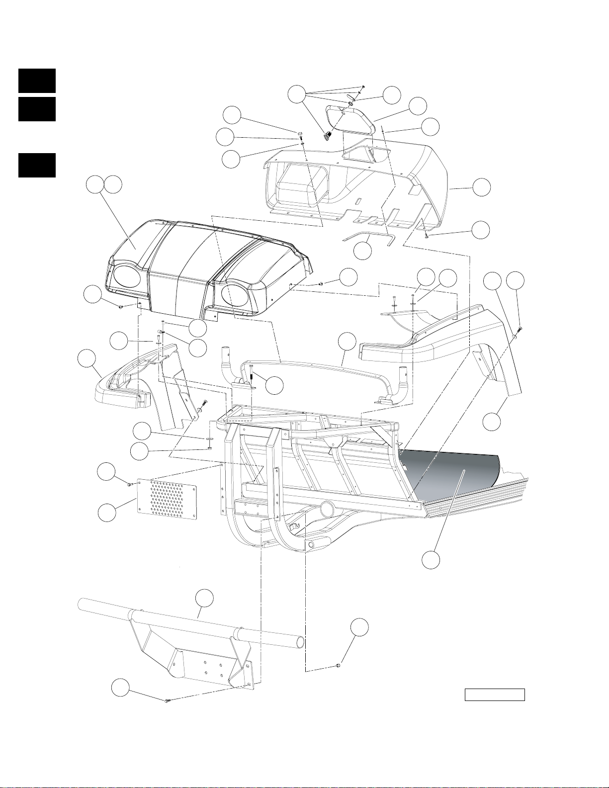
FRONT BODY TRIM, GASOLINE VEHICLES
ITEM PART NO. DESCRIPTION
1 2 3 4
1 603 00 02-22 Washer, 1/4" Type B Flat ..................................................................................................... 7
2 603 00 06-74 Fender, Left Front ................................................................................................................ 1
3 603 00 06-76 Fender, Right Front .............................................................................................................. 1
4 603 00 06-78 Dashboard with Access Hole ............................................................................................... 1
5 603 00 07-29 Cap, 1/4" Plastic Screw Head ............................................................................................. 5
6 603 00 07-37 Washer, 1/4 Id Scalloped Plast ............................................................................................ 5
7 603 00 08-70 Screw, M8 X 1.25 X 30 Tri, Blk ............................................................................................ 4
8 603 00 08-75 Bolt, Flange Head, M8 X 30.0 ............................................................................................. 4
9 603 00 09-66 P-Clamp, Insulated .312 In .................................................................................................. 1
10 603 00 09-89 Weldment, Support, ROPS .................................................................................................. 1
11 603 00 10-04 Grill, Flat .............................................................................................................................. 1
12 603 00 10-11 Mat, Floor ............................................................................................................................ 1
13 603 00 11-51 Support, Access Panel, Dash .............................................................................................. 1
14 603 00 11-74 Washer Hard,m10 ............................................................................................................... 4
15 603 00 11-81 Rivet, .125" Dia, .311" Panel ............................................................................................... 5
16 603 00 13-00 Nut Flg M10 X 1.5 Mech Def ............................................................................................... 4
17 603 00 13-08 Lock Nut, Flg M8 X 1.25 Nylon ............................................................................................ 4
18 603 00 13-25 Screw, 1/4-20 X 1.0 Pn Hd Torx .......................................................................................... 13
19 603 00 16-75 Cowl, Camo ......................................................................................................................... 1
20 603 00 16-76 Cowl, Orange ....................................................................................................................... 1
21 603 00 17-69 Brush Guard ........................................................................................................................ 1
22 603 00 27-66 Panel, Access, Dash ........................................................................................................... 1
23 603 00 27-78 Cam Lock Body ................................................................................................................... 1
24 603 00 27-85 Latch, Cam, Access Panel .................................................................................................. 1
25 603 00 06-95 Rivet, Removable, Tuflok 1/4" ............................................................................................. 15
26 603 00 04-48 Bolt, M10 X 1.50 X 65 .......................................................................................................... 4
QTY
1
G
E
D
2005 HUV4420 and HUV4420-D Gasoline and Diesel Vehicles Illustrated Parts List Page 1-3
Page 12
1
G
E
TYPICAL
5 PLACES
17
22
5
23
21
14
TYPICAL
5 PLACES
D
TYPICAL
2 PLACES
3
TYPICAL
4 PLACES
7
18
25
19
TYPICAL
4 PLACES
15
13
17
6
4
TYPICAL
25
7 PLACES
12
TYPICAL
25
6 PLACES
9
TYPICAL
26
4 PLACES
10
TYPICAL
3 PLACES
17
TYPICAL
4 PLACES
1
17
1
2
24
20
TYPICAL
16
4 PLACES
TYPICAL
4 PLACES
8
Page 1-4 2005 HUV4420 and HUV4420-D Gasoline and Diesel Vehicles Illustrated Parts List
11
000149-001
Page 13

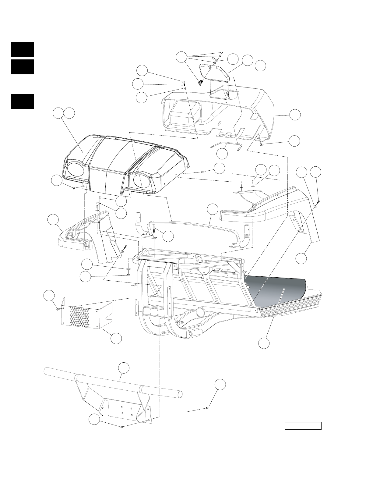
FRONT BODY TRIM, DIESEL VEHICLES
ITEM PART NO. DESCRIPTION
1 2 3 4
1 603 00 02-22 Washer, 1/4" Type B Flat ..................................................................................................... 7
2 603 00 06-74 Fender, Left Front ................................................................................................................ 1
3 603 00 06-76 Fender, Right Front .............................................................................................................. 1
4 603 00 06-78 Dashboard with Access Hole ............................................................................................... 1
5 603 00 07-29 Cap, 1/4" Plastic Screw Head ............................................................................................. 5
6 603 00 07-37 Washer, 1/4 Id Scalloped Plast ............................................................................................ 5
7 603 00 08-70 Screw, M8 X 1.25 X 30 Tri, Blk ............................................................................................ 4
8 603 00 08-75 Bolt, Flange Head, M8 X 30.0 ............................................................................................. 4
9 603 00 09-66 P-Clamp, Insulated .312 In .................................................................................................. 1
10 603 00 09-89 Weldment, Support, ROPS .................................................................................................. 1
11 603 00 10-11 Mat, Floor ............................................................................................................................ 1
12 603 00 11-51 Support, Access Panel, Dash .............................................................................................. 1
13 603 00 11-74 Washer Hard,m10 ............................................................................................................... 4
14 603 00 11-81 Rivet, .125" Dia, .311" Panel ............................................................................................... 5
15 603 00 13-00 Nut Flg M10 X 1.5 Mech Def ............................................................................................... 4
16 603 00 13-08 Lock Nut, Flg M8 X 1.25 Nylon ............................................................................................ 4
17 603 00 13-25 Screw, 1/4-20 X 1.0 Pn Hd Torx .......................................................................................... 13
18 603 00 16-75 Cowl, Camo ......................................................................................................................... 1
19 603 00 16-76 Cowl, Orange ....................................................................................................................... 1
20 603 00 17-69 Brush Guard ........................................................................................................................ 1
21 603 00 27-66 Panel, Access, Dash ........................................................................................................... 1
22 603 00 27-78 Cam Lock Body ................................................................................................................... 1
23 603 00 27-85 Latch, Cam, Access Panel .................................................................................................. 1
24 603 00 10-58 Guard, Radiator ................................................................................................................... 1
25 603 00 06-95 Rivet, Removable, Tuflok 1/4" ............................................................................................. 15
26 603 00 04-48 Bolt, M10 X 1.50 X 65 .......................................................................................................... 4
QTY
1
G
E
D
2005 HUV4420 and HUV4420-D Gasoline and Diesel Vehicles Illustrated Parts List Page 1-5
Page 14
1
G
E
D
TYPICAL
3 PLACES
6
7
9
2
9
8
3
1
4
TYPICAL
8 PLACES
TYPICAL
6
7
TYPICAL
7
4 PLACES
5
4 PLACES
Page 1-6 2005 HUV4420 and HUV4420-D Gasoline and Diesel Vehicles Illustrated Parts List
000017-001
Page 15

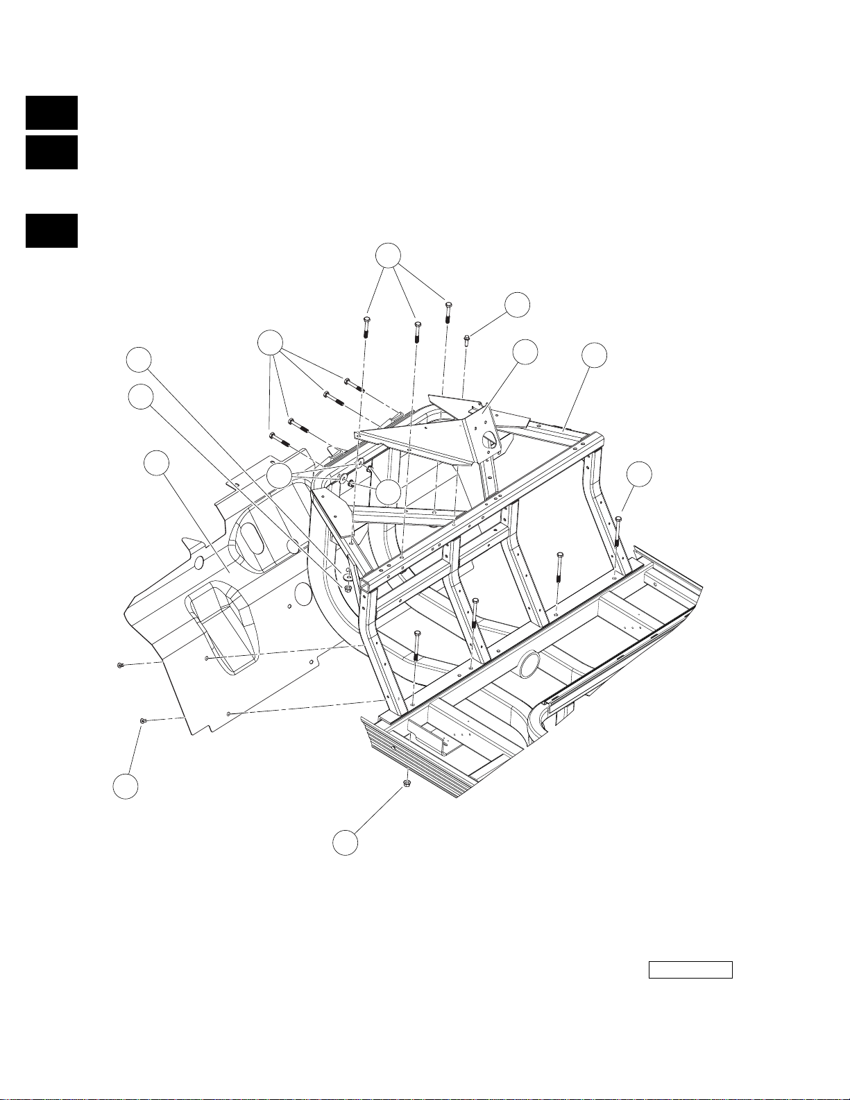
FRONT BODY COMPONENTS
ITEM PART NO. DESCRIPTION
1 2 3 4
1 603 00 03-79 Blind Rivet, Push Type ........................................................................................................ 8
2 603 00 08-69 Screw, M8X1.25X30, Hex .................................................................................................... 1
3 **** Weldment, Dash, Front ........................................................................................................ 1
4 603 00 10-24 Guard, Splash ...................................................................................................................... 1
5 603 00 17-59 Bolt, M10x1.50x100 (Black) ................................................................................................. 4
6 603 00 11-74 Washer Hard,m10 ............................................................................................................... 7
7 603 00 13-00 Nut Flg M10 X 1.5 Mech Def ............................................................................................... 11
8 **** Bracket, Support, S te eri ng ............ ..... ...... ....................................... ...... ............................... 1
9 603 00 04-48 Bolt, M10 X 1.50 X 65 .......................................................................................................... 7
**** Special order item available upon request.
QTY
1
G
E
D
2005 HUV4420 and HUV4420-D Gasoline and Diesel Vehicles Illustrated Parts List Page 1-7
Page 16
1
G
E
D
5
17
28
19
23
22
TYPICAL
4 PLACES
21
20
TYPICAL
2 PLACES
24
TYPICAL
4 PLACES
26
25
29
27
TYPICAL
4 PLACES
16
10
12
TYPICAL
2 PLACES
14
8
18
15
7
13
6
9
11
TYPICAL
4 PLACES
TYPICAL
31
4 PLACES
TYPICAL
2 PLACES
1
3
30
4
2
Page 1-8 2005 HUV4420 and HUV4420-D Gasoline and Diesel Vehicles Illustrated Parts List
000028-001
Page 17

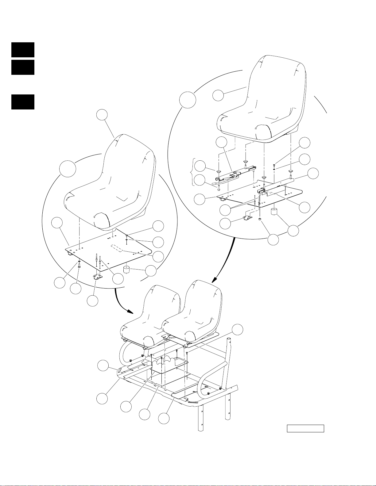
FRONT SEATS AND CUP HOLDER
ITEM PART NO. DESCRIPTION
1 2 3 4
1 603 00 02-29 Tape, Vinyl Foam 1/8" x 3/4" ............................................................................................... 2
2 603 00 09-98 Closeout, Driver Side ........................................................................................................... 1
3 603 00 09-99 Closeout, Passenger Side ................................................................................................... 1
4 603 00 10-49 Pan, Center, Closeout ......................................................................................................... 1
5 531 30 82-51 Asm, Bucket Seat Adjustable (includes items 6 through 18) ............................................... 1
6 603 00 01-25 Hinge Plate ..................................................................................................................... 2
7 603 00 07-36 Rivet, 1/4 X .438 Blind .................................................................................................... 4
8 603 00 07-74 Screw, 6m-1.00 X 10mm Hex Head ................................................................................ 1
9 603 00 07-77 Seat Holder Cup ............................................................................................................. 1
10 603 00 08-75 Bolt, Flange Head, M8 X 30.0 ......................................................................................... 4
11 603 00 12-98 Nut,m8,all Metal Lock ..................................................................................................... 4
12 603 00 10-93 Pan, Seat, Driver Asm .................................................................................................... 1
13 603 00 11-02 Decal, Hot Surface Warning ............................................................................................ 1
14 603 00 11-37 Adjuster, Forward/Aft ...................................................................................................... 1
15 603 00 11-38 Adjuster, Slider ................................................................................................................ 1
16 603 00 11-45 Washer, Bell .................................................................................................................... 4
17 603 00 40-79 Seat, Bucket, Gray .......................................................................................................... 1
18 603 00 00-58 Lockwasher, 1/4 Helical Split .......................................................................................... 1
19 N/A Assembly, Bucket Seat w/Spacers (includes items 20 through 29) ..................................... 1
20 603 00 01-25 Hinge Plate ..................................................................................................................... 2
21 603 00 05-79 Screw, M8-125 X 22 Hex-Head ......................................................................................4
22 603 00 01-84 Lockwasher, 8mm Split ................................................................................................... 4
23 603 00 06-89 Pan, Seat, Passenger ..................................................................................................... 1
24 603 00 07-36 Rivet, 1/4 X .438 Blind .................................................................................................... 4
25 603 00 07-74 Screw, 6m-1.00 X 10mm Hex Head ................................................................................ 1
26 603 00 07-77 Seat Holder Cup ............................................................................................................. 1
27 603 00 11-02 Decal, Hot Surface Warning ............................................................................................ 1
28 603 00 40-79 Seat, Bucket, Gray .......................................................................................................... 1
29 603 00 00-58 Lockwasher, 1/4 Helical Split .......................................................................................... 1
30 603 00 11-61 Console, Center, Drink Holder ............................................................................................. 1
31 603 00 06-95 Rivet, Removable, Tuflok 1/4" ............................................................................................. 4
QTY
1
G
E
D
2005 HUV4420 and HUV4420-D Gasoline and Diesel Vehicles Illustrated Parts List Page 1-9
Page 18
1
G
5
3
4
E
D
12
11
10
15
TYPICAL
8 PLACES
14
13
TYPICAL
2 PLACES
22
25
21
TYPICAL
2 PLACES
8
20
19
TYPICAL
2 PLACES
21
6
23
16
21
TYPICAL
2 PLACES
2
27
7
TYPICAL
4 PLACES
26
TYPICAL
2 PLACES
1
17
18
9
TYPICAL
2 PLACES
20
24
FRONT
OF VEHICLE
TYPICAL
4 PLACES
Page 1-10 2005 HUV4420 and HUV4420-D Gasoline and Diesel Vehicles Illustrated Parts List
000029-001
Page 19

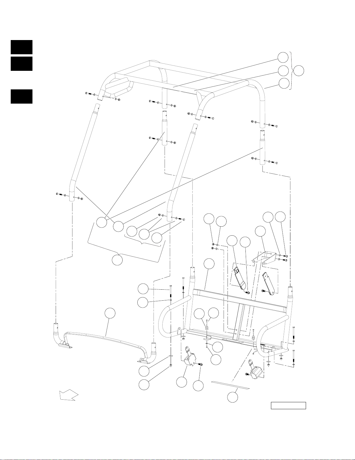
ROPS
ITEM PART NO. DESCRIPTION
1 2 3 4
1 603 00 05-58 Locknut, M6-1.00 Nylon Insert ............................................................................................. 2
2 603 00 07-73 Seat Holder Base ................................................................................................................ 2
3 603 00 09-88 Weldment, Top, ROPS (includes items 4 through 6) ........................................................... 1
4 603 00 11-06 Decal, Young Driver Warning .......................................................................................... 1
5 603 00 13-14 Decal, ROPS Certification/Warning ................................................................................ 1
6 603 00 36-06 Weldment, ROPS, Top, Unlabeled .................................................................................. 1
7 603 00 09-89 Weldment, Support, ROPS .................................................................................................. 1
8 603 00 10-65 Buckle, Seat Belt with Sleeve .............................................................................................. 2
9 603 00 10-66 Retractor, Seat Belt ............................................................................................................. 2
10 603 00 11-60 Kit, ROPS (includes items 11 through 15) ........................................................................... 1
11 603 00 09-90 Tube, Support, Front, ROPS ........................................................................................... 2
12 603 00 09-91 Tube, Support, Rear, ROPS ............................................................................................ 2
13 603 00 16-72 Bolt, M10 X 55, Zn-Ni (Black) ......................................................................................... 8
14 603 00 16-73 Washer, Hard, M10, Zn-Ni/Blk ........................................................................................ 16
15 603 00 16-74 Nut, Hex Cap, M10, Zn-Ni/Blk ......................................................................................... 8
16 603 00 17-59 Bolt, M10x1.50x100 (Black) ................................................................................................. 4
17 603 00 11-74 Washer Hard,m10 ............................................................................................................... 4
18 603 00 13-00 Nut Flg M10 X 1.5 Mech Def ............................................................................................... 4
19 603 00 15-85 Bracket, Seatbelt, Bolt-On ................................................................................................... 1
20 603 00 15-89 Screw,m12x1.75x30 Thd Form Blk ...................................................................................... 4
21 603 00 16-73 Washer, Hard, M10, Zn-Ni/Blk ............................................................................................. 8
22 603 00 16-74 Nut, Hex Cap, M10, Zn-Ni/Blk ............................................................................................. 2
23 603 00 17-60 Bolt, M10 X 45, Zn-Ni (Black) .............................................................................................. 2
24 603 00 17-66 Barrier, Heat, Neoprene ....................................................................................................... 1
25 603 00 09-87 Weldment, Supp, Seat, Rops .............................................................................................. 1
26 603 00 00-54 Washer, 1/4 Type A Narrow Flat .......................................................................................... 2
27 603 00 04-52 Bolt, M6 X 1 X 45 ................................................................................................................. 2
QTY
1
G
E
D
2005 HUV4420 and HUV4420-D Gasoline and Diesel Vehicles Illustrated Parts List Page 1-11
Page 20
1
G
E
D
11
8
9.4 FEET
15
TYPICAL
8 PLACES
7
9
12
13
14
TYPICAL
2 PLACES
TYPICAL
4 PLACES
15
10
TYPICAL
4 PLACES
TYPICAL
2 PLACES
19
18
3
2
TYPICAL
2 PLACES
1
3
16
4
5
17
TYPICAL
2 PLACES
000157-001
Page 1-12 2005 HUV4420 and HUV4420-D Gasoline and Diesel Vehicles Illustrated Parts List
Page 21

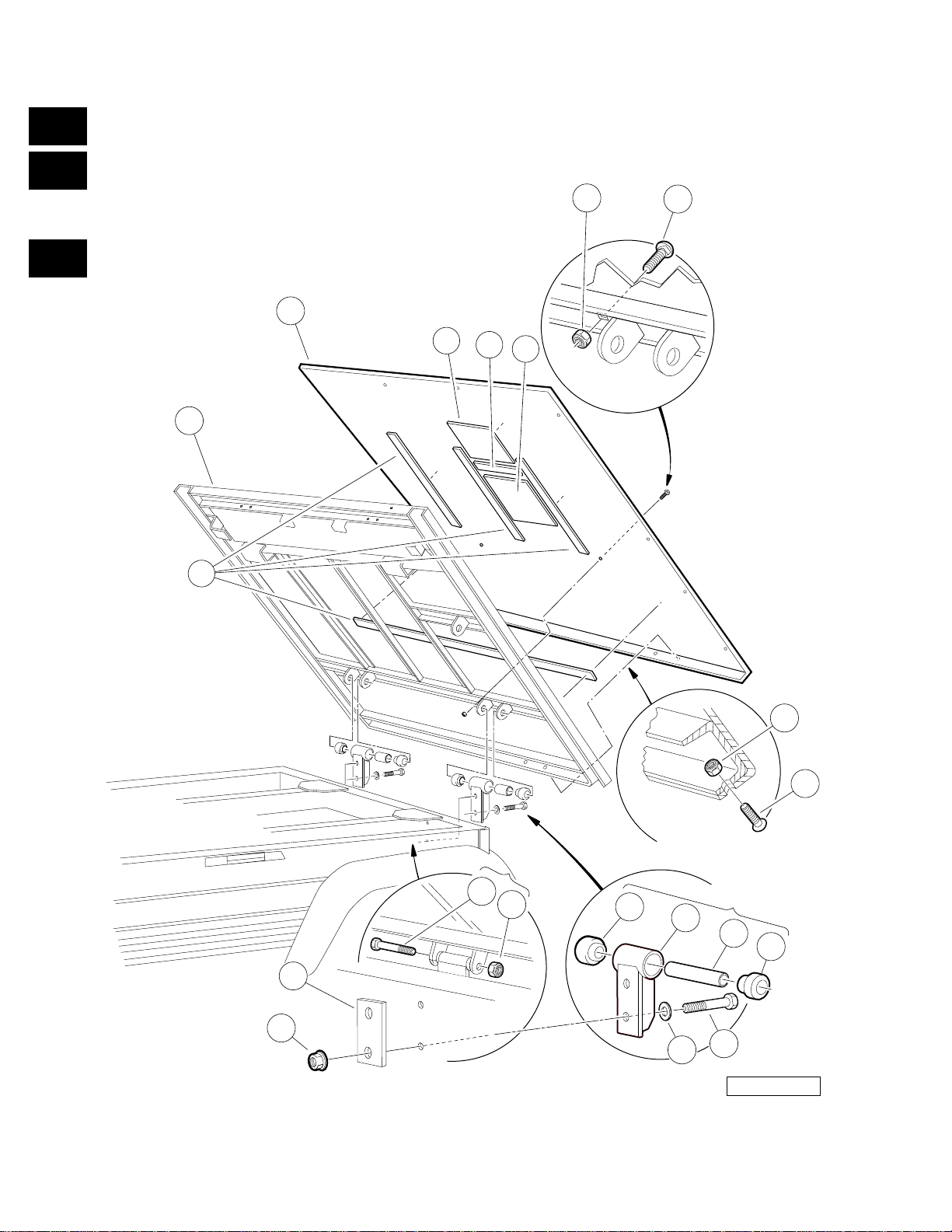
TILT BED AND HINGE
ITEM PART NO. DESCRIPTION
1 2 3 4
1 603 00 01-36 Bushing, Steel ..................................................................................................................... 2
2 603 00 02-50 Hinge ................................................................................................................................... 2
3 603 00 02-63 Bushing, Urethane ............................................................................................................... 2
4 603 00 07-80 Locknut, 3/8-16 Flanged Dimple .......................................................................................... 4
5 603 00 07-81 Washer, 3/8 Type B Hard Flat ............................................................................................. 4
6 603 00 07-97 Assembly, Tilt Bed, Electric Lift (includes items 7 through 14) ............................................ 1
7 603 00 01-07 Bolt, Carriage, 5/16-18 X 1.00 ........................................................................................ 4
8 603 00 02-29 Tape, Vinyl Foam 1/8" x 3/4" ........................................................................................... A/R
9 N/A Plate, Floor Bed ........................................................ ...... ...... ..... ...... ............................... 1
10 N/A Frame Assembly ............................................................................................................. A/R
11 603 00 02-55 Screw, 5/16-18 X 0.88 Torx Truss-Head ......................................................................... 4
12 603 00 18-12 Foam, Barrier, Heat, Bed, Frt .......................................................................................... 1
13 603 00 16-04 Foam, Barrier, Heat, Bed, Rail ........................................................................................ 1
14 603 00 00-78 Locknut, 5/16-18 Nylon Insert ......................................................................................... 8
15 603 00 12-86 Plate, Back .......................................................................................................................... 2
16 603 00 00-80 Bolt, 3/8-16 X 3.00 Hex Head .............................................................................................. 4
17 603 00 00-95 Locknut, 3/8-16 Hex ............................................................................................................ 2
18 603 00 00-96 Screw, 3/8-16 X 3.375 Hex Cap .......................................................................................... 2
QTY
1
G
E
D
2005 HUV4420 and HUV4420-D Gasoline and Diesel Vehicles Illustrated Parts List Page 1-13
Page 22
1
G
E
D
2 PLACES
7
TYPICAL
TYPICAL
1
6
4 PLACES
6
15
TYPICAL
2 PLACES
14
14
5
13
2
5
TYPICAL
2 PLACES
10
14
6
8
9
14
6
4
6
TYPICAL
4 PLACES
15
3
13
15
2
8
REF.
12
16
TYPICAL
5 PLACES
Page 1-14 2005 HUV4420 and HUV4420-D Gasoline and Diesel Vehicles Illustrated Parts List
TYPICAL
2 PLACES
11
000158-001
Page 23

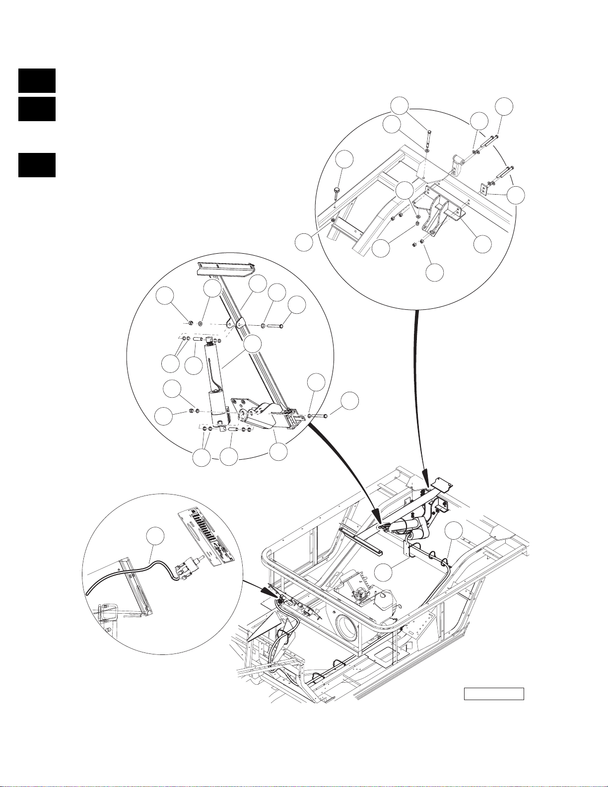
ELECTRIC BED LIFT
ITEM PART NO. DESCRIPTION
1 2 3 4
1 603 00 01-06 Bolt, 3/8-16 X 4.25 Hex Head .............................................................................................. 1
2 603 00 03-65 Bushing Long ....................................................................................................................... 2
3 603 00 03-84 Actuator Assembly, Electric ................................................................................................. 1
4 603 00 03-85 Asm, Actuator Adapter ........................................................................................................ 1
5 603 00 04-34 Body Spacer ........................................................................................................................ 8
6 603 00 07-81 Washer, 3/8 Type B Hard Flat ............................................................................................. 8
7 603 00 10-01 Bumper, Bed, Mtg, Front ..................................................................................................... 2
8 603 00 11-27 Weldment, Bracket, Actuator ............................................................................................... 1
9 603 00 12-86 Plate, Back .......................................................................................................................... 1
10 603 00 13-08 Lock Nut, Flg M8 X 1.25 Nylon ............................................................................................ 2
11 603 00 13-27 Tie Wrap, 8.00" With Mount ................................................................................................. 2
12 603 00 15-95 Wire Harness, Electric Lift ................................................................................................... 1
13 603 00 00-56 Washer, Lock, Hel Sp 3/8 Reg ............................................................................................. 2
14 603 00 00-95 Locknut, 3/8-16 Hex ............................................................................................................ 9
15 603 00 00-96 Screw, 3/8-16 X 3.375 Hex Cap .......................................................................................... 6
16 603 00 29-63 Tie Wrap, 8" Nylon ............................................................................................................... 5
QTY
1
G
E
D
2005 HUV4420 and HUV4420-D Gasoline and Diesel Vehicles Illustrated Parts List Page 1-15
Page 24
1
G
E
D
TYPICAL 4
PLACES
4
9
TYPICAL 4
PLACES
24
26
11
TYPICAL 2
PLACES
1
25
10
21
17
TYPICAL 2
12
6
TYPICAL 16
PLACES
PLACES
25
16
5
8
13
3
4
25
6
7
PASSENGER SIDE
DRIVER SIDE
19
20
14
22
TYPICAL 4
15
PLACES
18
TYPICAL 2
PLACES
2
TYPICAL 4
PLACES
23
Page 1-16 2005 HUV4420 and HUV4420-D Gasoline and Diesel Vehicles Illustrated Parts List
000038-002
Page 25

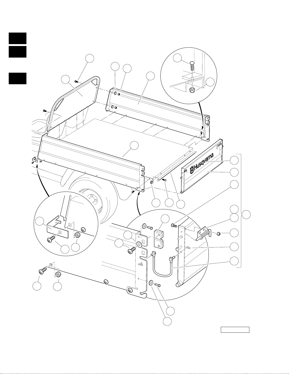
CARGO BOX
ITEM PART NO. DESCRIPTION
1 2 3 4
1 603 00 01-07 Bolt, Carriage, 5/16-18 X 1.00 ............................................................................................. 13
2 603 00 01-08 Bumper, Rubber .................................................................................................................. 4
3 603 00 02-22 Washer, 1/4" Type B Flat ..................................................................................................... 4
4 603 00 02-26 Screw, 1/4-20 X 0.75 Torx Truss-Head ................................................................................ 8
5 603 00 02-32 Stud, Self-Clinching Flush Head .......................................................................................... 4
6 603 00 02-55 Screw, 5/16-18 X 0.88 Torx Truss-Head .............................................................................. 18
7 603 00 05-73 Box Bed Tailgate Angle ....................................................................................................... 1
8 603 00 06-16 Locknut, 5/16-18 Hex Flange .............................................................................................. 4
9 603 00 08-02 Front Panel Weldment ......................................................................................................... 1
10 603 00 08-03 Left Panel Weldment ........................................................................................................... 1
11 603 00 08-04 Right Panel Weldment ......................................................................................................... 1
12 603 00 08-05 Front Corner Cap ................................................................................................................. 2
13 603 00 08-07 Slam Latch ........................................................................................................................... 2
14 603 00 08-13 Assembly, Tailgate (includes items 15 through 22) ............................................................. 1
15 603 00 01-72 Hair Pin Clip .................................................................................................................... 4
16 603 00 02-26 Screw, 1/4-20 X 0.75 Torx Truss-Head ........................................................................... 4
17 N/A Tailgate, Weldment ......................................................................................................... 1
18 603 00 08-06 Tether Assembly ............................................................................................................. 2
19 603 00 08-08 Spring Latch Left ............................................................................................................. 1
20 603 00 08-09 Spring Latch Right ........................................................................................................... 1
21 603 00 17-92 Decal, Husqvarna, Tailgate ............................................................................................. 1
22 603 00 00-89 Locknut, 1/4-20 Nylon Insert ........................................................................................... 4
23 603 00 08-16 Washer, Rubber, 3/8 ............................................................................................................ 4
24 603 00 00-54 Washer, 1/4 Type A Narrow Flat .......................................................................................... 4
25 603 00 00-78 Locknut, 5/16-18 Nylon Insert .............................................................................................. 31
26 603 00 00-89 Locknut, 1/4-20 Nylon Insert ................................................................................................ 4
QTY
1
G
E
D
2005 HUV4420 and HUV4420-D Gasoline and Diesel Vehicles Illustrated Parts List Page 1-17
Page 26
1
G
E
D
7
12
17
9
TYPICAL
TYPICAL
2 PLACES
14
2 PLACES
13
13
15
TYPICAL
5 PLACES
3
4
TYPICAL
2 PLACES
13
TYPICAL
4 PLACES
22
TYPICAL
4 PLACES
FRONT
OF VEHICLE
11
18
20
19
TYPICAL
4 PLACES
21
6
5
22
16
10
TYPICAL
4 PLACES
2
TYPICAL
1
8
2
22
TYPICAL
6 PLACES
2 PLACES
000150-001
Page 1-18 2005 HUV4420 and HUV4420-D Gasoline and Diesel Vehicles Illustrated Parts List
Page 27

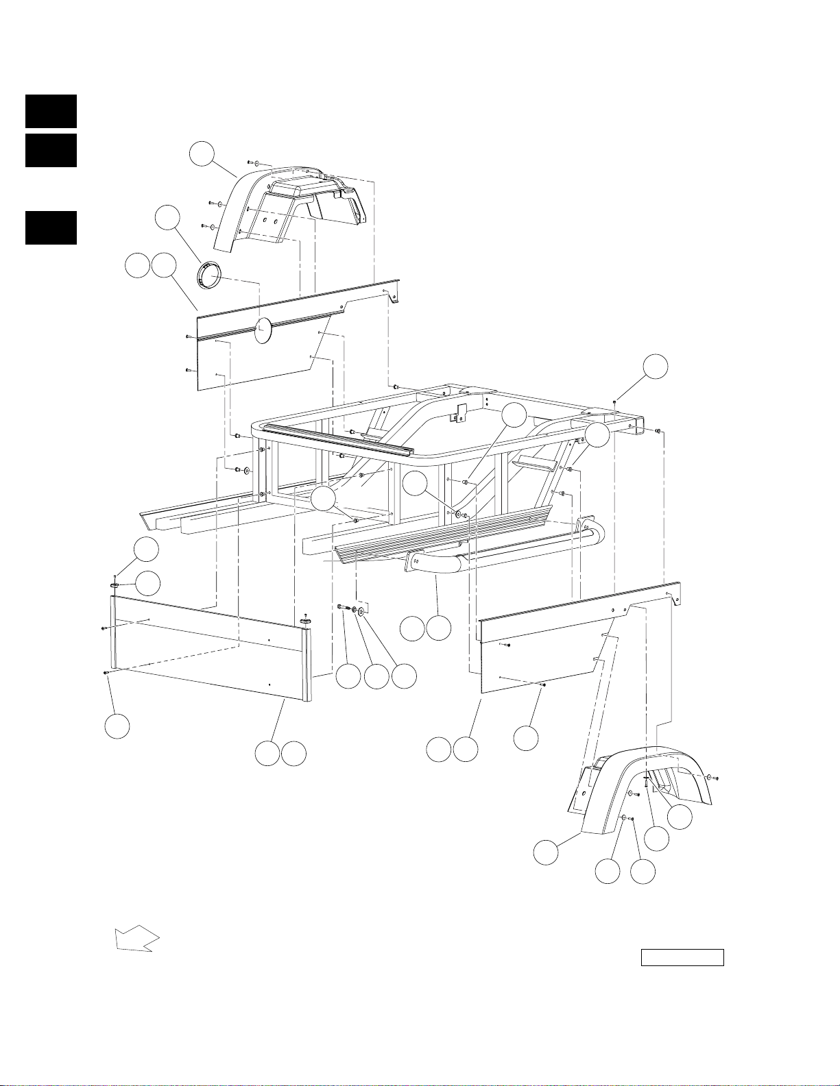
REAR BODY TRIM
ITEM PART NO. DESCRIPTION
1 2 3 4
1 603 00 01-57 Screw, M6-1.00 X 25mm Hex Cap ...................................................................................... 2
2 603 00 02-22 Washer, 1/4" Type B Flat ..................................................................................................... 8
3 603 00 02-23 Screw, #10 Truss-Head Torx ............................................................................................... 2
4 603 00 04-58 Corner Cap AWD ................................................................................................................. 2
5 603 00 06-93 Side Step Bar (black) ........................................................................................................... 2
6 603 00 06-94 Side Step Bar (orange) ........................................................................................................ 2
7 603 00 26-90 Fender, Right Rear .............................................................................................................. 1
8 603 00 26-91 Fender, Left Rear ................................................................................................................. 1
9 603 00 10-85 Assembly, Panel (Passenger Side) ..................................................................................... 1
10 603 00 10-86 Assembly, Panel (Driver Side) ............................................................................................. 1
11 603 00 10-87 Panel, Front ......................................................................................................................... 1
12 603 00 11-29 Bezel, Fuel Fill ..................................................................................................................... 1
13 603 00 11-76 Well Nut 1/4-20 .................................................................................................................... 14
14 603 00 13-17 Nut Flg, M6 X 1.0 Nylon ...................................................................................................... 2
15 603 00 15-99 Washer, M12 Hard Regular ................................................................................................. 2
16 603 00 17-74 Panel, Side, Driver, Steel ..................................................................................................... 1
17 603 00 17-75 Panel, Side, Passenger, Steel ............................................................................................. 1
18 603 00 17-76 Panel, Front, Steel ............................................................................................................... 1
19 603 00 00-56 Washer, Lock, Hel Sp 3/8 Reg ............................................................................................. 4
20 603 00 00-80 Bolt, 3/8-16 X 3.00 Hex Head .............................................................................................. 4
21 603 00 36-17 Washer, 3/8 Type B Flat ...................................................................................................... 4
22 603 00 00-91 Screw, 1/4-20 X 1.0 Truss-Head Machine ...........................................................................14
QTY
1
G
E
D
2005 HUV4420 and HUV4420-D Gasoline and Diesel Vehicles Illustrated Parts List Page 1-19
Page 28
1
G
E
D
4
5
2
TYPICAL
34 PLACES
Page 1-20 2005 HUV4420 and HUV4420-D Gasoline and Diesel Vehicles Illustrated Parts List
3
000165-001
Page 29

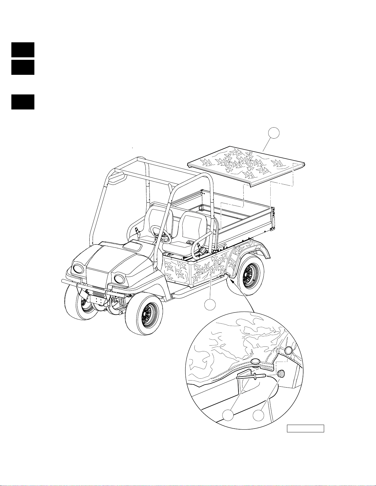
CAMOUFLAGE COVERS
ITEM PART NO. DESCRIPTION
1 2 3 4
1 603 00 00-45 Kit, Camouflage Cover (includes items 2 through 5) ........................................................... 1
2 N/A Rivet, 0.125" Dia. ........................................... ....................................... ...... ...... .............. 34
3 N/A Snap, Male Button, 7/16" ................................................................................................ 34
4 603 00 00-26 Cover, Camouflage Cargo Box (Forest Floor Pattern) .................................................... 1
5 531 30 10-26 Wrap, Camouflage Rear Body (Forest Floor Pattern) ..................................................... 1
QTY
1
G
E
D
2005 HUV4420 and HUV4420-D Gasoline and Diesel Vehicles Illustrated Parts List Page 1-21
Page 30

1
G
E
D
Page 31

WHEELS AND TIRES
2
G
E
D
Page 32

2
G
E
D
ALL TERRAIN TREAD
"ALL TRAIL"
9
4
1
3
2
Page 2-2 2005 HUV4420 and HUV4420-D Gasoline and Diesel Vehicles Illustrated Parts List
8
7
6
5
000162-001
Page 33

WHEELS AND TIRES, ALL-TERRAIN TREAD
ITEM PART NO. DESCRIPTION
1 2 3 4
1 603 00 06-70 Gray Tire Assembly, HDAT, 8-Inch (includes items 2 through 4) ......................................... 2
2 603 00 06-67 HDAT Tire, 8" .................................................................................................................. 1
3 603 00 00-32 Wheel, Indus Spider, Gray .............................................................................................. 1
4 603 00 00-33 Valve Stem ...................................................................................................................... 1
5 603 00 06-71 Gray Tire Assembly, HDAT 10.5-Inch (includes items 6 through 8) .................................... 2
6 603 00 06-65 Tire, HDAT ...................................................................................................................... 1
7 603 00 00-32 Wheel, Indus Spider, Gray .............................................................................................. 1
8 603 00 00-33 Valve Stem ...................................................................................................................... 1
9 603 00 00-34 Nut, Lug, 1/2-20 SAE J2283 ................................................................................................ 16
QTY
2
G
E
D
2005 HUV4420 and HUV4420-D Gasoline and Diesel Vehicles Illustrated Parts List Page 2-3
Page 34

2
G
E
D
DIRECTION
OF FORWARD
ROTATATION
DIRECTION
OF FORWARD
ROTATION
MUD TREAD
"AT489"
9
DIRECTION
OF FORWARD
ROTATION
8
7
6
Page 2-4 2005 HUV4420 and HUV4420-D Gasoline and Diesel Vehicles Illustrated Parts List
5
4
3
2
000177-001
1
Page 35

WHEELS AND TIRES, MUD TREAD
ITEM PART NO. DESCRIPTION
1 2 3 4
1 603 00 00-30 Gray Tire Assembly, AT489 LH (includes items 2 through 4) .............................................. 2
2 603 00 00-31 Tire, AT489 ...................................................................................................................... 1
3 603 00 00-32 Wheel, Indus Spider, Gray .............................................................................................. 1
4 603 00 00-33 Valve Stem ...................................................................................................................... 1
5 603 00 06-72 Gray Tire Assembly, AT489 RH (includes items 6 through 8) ............................................. 2
6 603 00 00-31 Tire, AT489 ...................................................................................................................... 1
7 603 00 00-32 Wheel, Indus Spider, Gray .............................................................................................. 1
8 603 00 00-33 Valve Stem ...................................................................................................................... 1
9 603 00 00-34 Nut, Lug, 1/2-20 SAE J2283 ................................................................................................ 16
QTY
2
G
E
D
2005 HUV4420 and HUV4420-D Gasoline and Diesel Vehicles Illustrated Parts List Page 2-5
Page 36

2
G
E
D
Page 37

DECALS
3
G
E
D
Page 38

3
G
E
D
5
7
2
9
(TOP OF PASSENGER-SIDE
VEHICLE FRAME)
4
3
(ON REAR RECEIVER HITCH)
8
6
(HIGH CAPACITY OPTION)
Page 3-2 2005 HUV4420 and HUV4420-D Gasoline and Diesel Vehicles Illustrated Parts List
(STANDARD VEHICLE)
(ON DRIVER-SIDE
AND PASSENGER-SIDE)
1
000170-001
Page 39

SAFETY DECALS, GASOLINE DECALS
ITEM PART NO. DESCRIPTION
1 2 3 4
1 603 00 01-23 Decal, Trailer Hitch .............................................................................................................. 1
2 603 00 04-63 Decal, Bed Load Warning .................................................................................................... 1
3 603 00 04-66 Decal, Crush Area Warning ................................................................................................. 2
4 603 00 08-11 Decal, Rotating Parts Warning ............................................................................................ 1
5 603 00 11-06 Decal, Young Driver Warning .............................................................................................. 1
6 603 00 11-08 Decal, Vehicle Loading, High-Capacity ............................................................................... 1
7 603 00 13-14 Decal, ROPS Certification/Warning ..................................................................................... 1
8 603 00 15-96 Decal, Vehicle Loading, Standard Capacity ......................................................................... 1
9 603 00 17-67 Decal, Warning, Gasoline Instrument Panel ........................................................................ 1
QTY
3
G
E
D
2005 HUV4420 and HUV4420-D Gasoline and Diesel Vehicles Illustrated Parts List Page 3-3
Page 40

3
G
E
D
(ON PASSENGER SIDE
SEAT SUPPORT)
1
(ON PANEL BETWEEN
SEATS OR ON OPTIONAL
CONSOLE/CUP HOLDER)
3
4
(ON UNDERSIDE
OF EACH SEAT
AND ON CROSSBAR
BEHIND SEATS)
2
(FOR VEHICLES WITH WINCH ACCESSORY)
(ON FRONT BODY)
(ON VEHICLE FRAME)
(ON DRIVER-SIDE VEHICLE FRAME)
5
Page 3-4 2005 HUV4420 and HUV4420-D Gasoline and Diesel Vehicles Illustrated Parts List
6
000171-001
Page 41

SAFETY DECALS, GASOLINE VEHICLES, CONTINUED
ITEM PART NO. DESCRIPTION
1 2 3 4
1 603 00 04-62 Decal, Gasoline Explosion/Fire Warning ............................................................................. 1
2 603 00 08-14 Decal, Winch Cable Fracture Warning ................................................................................ 1
3 603 00 10-90 Decal, Operating Instructions, Gasoline .............................................................................. 1
4 603 00 11-02 Decal, Hot Surface Warning ................................................................................................ 3
5 603 00 11-04 Decal, Frame Ground Warning ............................................................................................ 1
6 603 00 11-07 Decal, Rotating Parts and Hot Exhaust Warning ................................................................. 1
QTY
3
G
E
D
2005 HUV4420 and HUV4420-D Gasoline and Diesel Vehicles Illustrated Parts List Page 3-5
Page 42

3
G
E
D
5
8
2
10
(ON PASSENGER-SIDE
VEHICLE BODY)
4
7
(TOP OF PASSENGER-SIDE
VEHICLE FRAME)
3
(ON DRIVER-SIDE
AND PASSENGER-SIDE)
9
6
Page 3-6 2005 HUV4420 and HUV4420-D Gasoline and Diesel Vehicles Illustrated Parts List
1
000172-001
Page 43

SAFETY DECALS, DIESEL VEHICLES
ITEM PART NO. DESCRIPTION
1 2 3 4
1 603 00 01-23 Decal, Trailer Hitch .............................................................................................................. 1
2 603 00 04-63 Decal, Bed Load Warning .................................................................................................... 1
3 603 00 04-66 Decal, Crush Area Warning ................................................................................................. 2
4 603 00 11-01 Decal, Diesel Fuel Only ....................................................................................................... 1
5 603 00 11-06 Decal, Young Driver Warning .............................................................................................. 1
6 603 00 11-08 Decal, Vehicle Loading, High-Capacity ............................................................................... 1
7 603 00 11-09 Decal, Rotating Parts Warning ............................................................................................ 1
8 603 00 13-14 Decal, ROPS Certification/Warning ..................................................................................... 1
9 603 00 15-96 Decal, Vehicle Loading, Standard Capacity ......................................................................... 1
10 603 00 17-68 Decal, Warning, Diesel Instrument Panel ............................................................................ 1
QTY
3
G
E
D
2005 HUV4420 and HUV4420-D Gasoline and Diesel Vehicles Illustrated Parts List Page 3-7
Page 44

3
G
E
D
(ON ENGINE
VALVE COVER)
(ON PASSENGER-SIDE
SEAT SUPPORT)
8
4
6
(ON PANEL BETWEEN
SEATS OR ON OPTIONAL CONSOLE/
CUP HOLDER)
2
1
(FOR VEHICLES WITH WINCH ACCESSORY)
(ON FRONT BODY)
3
(ON COOLANT PIPES, UNDERSIDE OF
EACH SEAT, AND CROSSBAR
BEHIND SEATS)
5
7
(ON VEHICLE FRAME NEAR BATTERY)
(ON DRIVER-SIDE VEHICLE FRAME)
000173-001
Page 3-8 2005 HUV4420 and HUV4420-D Gasoline and Diesel Vehicles Illustrated Parts List
Page 45

SAFETY DECALS, DIESEL VEHICLES, CONTINUED
ITEM PART NO. DESCRIPTION
1 2 3 4
1 603 00 08-14 Decal, Winch Cable Fracture Warning ................................................................................ 1
2 603 00 10-91 Decal, Operating Instructions, Diesel .................................................................................. 1
3 603 00 11-02 Decal, Hot Surface Warning ................................................................................................ 5
4 603 00 11-03 Decal, Hot Manifold Warning ............................................................................................... 1
5 603 00 11-04 Decal, Frame Ground Warning ............................................................................................ 1
6 603 00 11-05 Decal, Diesel Explosion/Fire Warning ................................................................................. 1
7 603 00 11-07 Decal, Rotating Parts and Hot Exhaust Warning ................................................................. 1
8 603 00 11-09 Decal, Rotating Parts Warning ............................................................................................ 1
QTY
3
G
E
D
2005 HUV4420 and HUV4420-D Gasoline and Diesel Vehicles Illustrated Parts List Page 3-9
Page 46

3
G
E
D
6
2
5
4
3
1
7
Page 3-10 2005 HUV4420 and HUV4420-D Gasoline and Diesel Vehicles Illustrated Parts List
000174-001
Page 47

BADGING DECALS, HUV 4420
ITEM PART NO. DESCRIPTION
1 2 3 4
1 603 00 13-18 Decal, Diesel ....................................................................................................................... 2
2 603 00 15-94 Decal, High-Capacity (optional accessory) .......................................................................... 2
3 603 00 17-92 Decal, Husqvarna, Tailgate .................................................................................................. 1
4 603 00 17-93 Decal, Husqvarna Cowl ....................................................................................................... 1
5 603 00 17-94 Decal, Husqvarna, Side Panel ............................................................................................. 2
6 603 00 17-96 Decal, Bed ........................................................................................................................... 2
7 603 00 17-97 Decal, Bed ........................................................................................................................... 2
QTY
3
G
E
D
2005 HUV4420 and HUV4420-D Gasoline and Diesel Vehicles Illustrated Parts List Page 3-11
Page 48

3
G
E
D
Page 49

BRAKE SYSTEMS
4
G
E
D
Page 50

4
G
E
D
4
1
6
2
3
4
FRONT
5
OF VEHICLE
000067-001
Page 4-2 2005 HUV4420 and HUV4420-D Gasoline and Diesel Vehicles Illustrated Parts List
Page 51

FRONT BRAKE ASSEMBLY
ITEM PART NO. DESCRIPTION
1 2 3 4
1 603 00 08-98 Brake Caliper, Front, with Brake Pads ................................................................................. 2
2 603 00 11-62 Bolt, Banjo, M10x1x19 ......................................................................................................... 2
3 603 00 11-75 Washer, Copper, M10 Crush ............................................................................................... 4
4 603 00 11-83 Bolt Flange Head, 3/8-24x.750 with Loctite ......................................................................... 4
5 603 00 16-70 Service Kit, Brake Pad (4 Pads) .......................................................................................... 1
6 603 00 44-75 Pin, Slide, 7/16 .................................................................................................................... 2
QTY
4
G
E
D
2005 HUV4420 and HUV4420-D Gasoline and Diesel Vehicles Illustrated Parts List Page 4-3
Page 52

4
G
E
D
FRONT
OF VEHICLE
PASSENGER SIDE (NOT SHOWN)
2
DRIVER SIDE
1
5
5
8
6
4
3
000068-001
Page 4-4 2005 HUV4420 and HUV4420-D Gasoline and Diesel Vehicles Illustrated Parts List
Page 53

REAR BRAKE ASSEMBLY
ITEM PART NO. DESCRIPTION
1 2 3 4
1 603 00 09-45 Caliper, Brake, Hydro-Mechanical, LH ................................................................................ 1
2 603 00 09-46 Caliper, Brake, Hydro-Mechanical, RH ................................................................................ 1
3 603 00 11-62 Bolt, Banjo, M10x1x19 ......................................................................................................... 2
4 603 00 11-75 Washer, Copper, M10 Crush ............................................................................................... 4
5 603 00 11-83 Bolt Flange Head, 3/8-24x.750 with Loctite ......................................................................... 4
6 603 00 16-70 Service Kit, Brake Pad (4 Pads) .......................................................................................... 1
7 603 00 44-76 Spring, Brake Caliper Return ............................................................................................... 1
8 603 00 44-75 Pin, Slide, 7/16 .................................................................................................................... 2
QTY
4
G
E
D
2005 HUV4420 and HUV4420-D Gasoline and Diesel Vehicles Illustrated Parts List Page 4-5
Page 54

4
G
E
D
FRONT
OF VEHICLE
7
6
8
2
3
MAX
MIN
12
9
10
5
4
11
TYPICAL
2 PLACES
10
Page 4-6 2005 HUV4420 and HUV4420-D Gasoline and Diesel Vehicles Illustrated Parts List
1
000069-001
Page 55

MASTER CYLINDER
ITEM PART NO. DESCRIPTION
1 2 3 4
1 603 00 04-54 Clevis Pin, 5/16 X 1 ............................................................................................................. 1
2 603 00 02-22 Washer, 1/4" Type B Flat ..................................................................................................... 1
3 603 00 05-58 Locknut, M6-1.00 Nylon Insert ............................................................................................. 1
4 603 00 07-98 Pin, Rue ............................................................................................................................... 1
5 603 00 09-47 Cylinder, Master, Tandem .................................................................................................... 1
6 603 00 09-48 Assembly, Reservoir, Remote (includes items 7 and 8) ...................................................... 1
7 603 00 07-59 Filler Cap Asm ................................................................................................................ 1
8 N/A Reservoir, Brake Fluid, With ou t Cap ................................................ ............................... 1
9 603 00 11-98 Bolt, M 6 X 1.0 X 65 Hex, Flange, Head, Black ................................................................... 1
10 603 00 13-07 Bolt Flanged Head, M8 X 1.25 X 35 .................................................................................... 2
11 603 00 13-08 Lock Nut, Flg M8 X 1.25 Nylon ............................................................................................ 2
12 603 00 16-71 Line, Reservoir, Brake ......................................................................................................... 2
QTY
4
G
E
D
2005 HUV4420 and HUV4420-D Gasoline and Diesel Vehicles Illustrated Parts List Page 4-7
Page 56

4
G
E
D
TYPICAL
2 PLACES
3
98
2
TYPICAL
2 PLACES
6
15
5
4
TYPICAL
2 PLACES
4
10
2
1
11
4
TYPICAL
2 PLACES
12
7
13
Page 4-8 2005 HUV4420 and HUV4420-D Gasoline and Diesel Vehicles Illustrated Parts List
14
000015-001
Page 57

HYDRAULIC BRAKE LINES AND CLIPS
ITEM PART NO. DESCRIPTION
1 2 3 4
1 603 00 05-58 Locknut, M6-1.00 Nylon Insert ............................................................................................. 1
2 603 00 08-73 Bolt, Flanged Head, M6x1.0x40 .......................................................................................... 3
3 603 00 12-99 Nut-m6x1.0 Flng All Mtl Lock ............................................................................................... 2
4 603 00 08-74 Screw, M6 X 16 Tt Hx Fl Hd ................................................................................................ 7
5 603 00 09-53 Assembly, Brake Line, Rear ................................................................................................ 1
6 603 00 09-54 Assembly, Brakeline, Front (includes item 7) ......................................................................1
7 603 00 09-66 P-Clamp, Insulated .312 In ............................................................................................. 1
8 603 00 11-39 Bracket, Brake Line, Left ..................................................................................................... 1
9 603 00 11-40 Bracket, Brake Line, Right ................................................................................................... 1
10 603 00 11-41 Bracket, Tee, Brakeline ........................................................................................................ 1
11 603 00 11-43 Clip, Brake Line ................................................................................................................... 6
12 603 00 16-05 Bracket, Line, Hydraulic ....................................................................................................... 2
13 603 00 16-06 Brkt, Line, Hyd, Shk Mnt, Drv .............................................................................................. 1
14 603 00 16-07 Brkt, Line, Hyd, Shk Mnt, Pass ............................................................................................ 1
15 603 00 00-93 Tie Wrap, 11" Nylon ............................................................................................................. 1
QTY
4
G
E
D
2005 HUV4420 and HUV4420-D Gasoline and Diesel Vehicles Illustrated Parts List Page 4-9
Page 58

4
G
E
TYPICAL
2
TYPICAL
17
6
4 PLACES
8 PLACES
2
3
17
D
PARK BRAKE
CABLE
15
16
11
3
6
10
18
TYPICAL
2 PLACES
9
8
5
14
12
13
4
7
Page 4-10 2005 HUV4420 and HUV4420-D Gasoline and Diesel Vehicles Illustrated Parts List
TYPICAL
1
2 PLACES
000087-001
Page 59

PARK BRAKE ASSEMBLY WITH PULLEY SYSTEM
ITEM PART NO. DESCRIPTION
1 2 3 4
1 603 00 01-30 E-Clip, 1/2 ............................................................................................................................ 2
2 603 00 01-41 Locknut, #10-24 Nylon Insert ............................................................................................... 12
3 603 00 04-55 Screw, #10-24 X 3/4 Socket-Head ...................................................................................... 12
4 603 00 01-75 Spring, Brake Return ........................................................................................................... 1
5 603 00 06-32 Equalizer Bracket ................................................................................................................ 1
6 603 00 07-01 Pulley, 2-Inch Flat Mount ..................................................................................................... 3
7 603 00 10-53 Cable, Brake, Parking, Left .................................................................................................. 1
8 603 00 10-54 Cable, Brake, Parking, Right ............................................................................................... 1
9 603 00 13-06 Bolt Flanged Head, M8 X 1.25 X 65 .................................................................................... 1
10 603 00 13-08 Lock Nut, Flg M8 X 1.25 Nylon ............................................................................................ 1
11 603 00 11-79 Brake Cable, Park, Kit, Front (includes items 12 through 16) ............................................. 1
12 603 00 01-09 Nut, 5/16-24 Hex ............................................................................................................. 1
13 603 00 07-66 Nut, 5/16-24 Hex Cone ................................................................................................... 1
14 N/A Cable, Brake, Parking, Front ........................................................................................... 1
15 603 00 28-20 Ring, Retaining, External, 9mm ...................................................................................... 1
16 603 00 00-65 Washer, 5/16 Type A Flat ................................................................................................ 1
17 603 00 00-51 Washer, #10 Type A Flat ..................................................................................................... 12
18 603 00 00-93 Tie Wrap, 11" Nylon ............................................................................................................. 2
QTY
4
G
E
D
2005 HUV4420 and HUV4420-D Gasoline and Diesel Vehicles Illustrated Parts List Page 4-11
Page 60

4
G
E
D
6
1
13
5
14
4
12
Page 4-12 2005 HUV4420 and HUV4420-D Gasoline and Diesel Vehicles Illustrated Parts List
3
11
BOTTOM VIEW
10
2
7
8
000533-003
Page 61

PARK BRAKE ASSEMBLY WITH BELLCRANK SYSTEM
ITEM PART NO. DESCRIPTION
1 2 3 4
1 603 00 01-30 E-Clip, 1/2 ............................................................................................................................ 2
2 603 00 01-75 Spring, Brake Return ........................................................................................................... 1
3 603 00 06-32 Equalizer Bracket ................................................................................................................ 1
4 603 00 13-06 Bolt Flanged Head, M8 X 1.25 X 65 .................................................................................... 1
5 603 00 13-08 Lock Nut, Flg M8 X 1.25 Nylon ............................................................................................ 1
6 531 30 71-09 Cable, Crank, Bell, Front ..................................................................................................... 1
7 603 00 29-24 Cable, Noncoated, Pbrake, Left .......................................................................................... 1
8 603 00 29-25 Cable, Noncoated, Pbrake, Rght ......................................................................................... 1
9 603 00 29-30 Kit, Cable, Brake, Crank, Fr (includes items 10 through 13) ............................................... 1
10 603 00 01-09 Nut, 5/16-24 Hex ............................................................................................................. 1
11 603 00 07-66 Nut, 5/16-24 Hex Cone ................................................................................................... 1
12 N/A Cable, Crank, Bell, Main ................................................................................................. 1
13 603 00 00-63 Pin, 3/32 X 1.00 Sq Cut Cotter ........................................................................................ 1
14 603 00 00-93 Tie Wrap, 11" Nylon ............................................................................................................. 2
QTY
4
G
E
D
2005 HUV4420 and HUV4420-D Gasoline and Diesel Vehicles Illustrated Parts List Page 4-13
Page 62

4
G
E
D
Page 63

PEDAL GROUP
5
G
E
D
Page 64

5
G
E
D
2
6
7
18
5
3
17
8
15
19
19
2
11
18
4
12
10
9
16
4
13
14
Page 5-2 2005 HUV4420 and HUV4420-D Gasoline and Diesel Vehicles Illustrated Parts List
000026-001
Page 65

ACCELERATOR PEDAL ASSEMBLY
ITEM PART NO. DESCRIPTION
1 2 3 4
1 603 00 11-63 Asm, Pedal, Accelerator (includes items 2 through 17) ....................................................... 1
2 603 00 12-99 Nut-m6x1.0 Flng All Mtl Lock .......................................................................................... 3
3 N/A Pullrod, Spring, Compression ......................................................................................... 1
4 603 00 10-55 Bushing, Greaseless ....................................................................................................... 4
5 N/A Spring, Comp, Pedal, Pullrod .......................................................................................... 1
6 N/A Washer, Retaining Spring, 7mm ...................................................................................... 2
7 N/A Guide, Cable, Accelerator ............................................................................................... 1
8 N/A Weldment, Bracket, Pedal ............................. ...... ....................................... ...... .............. 1
9 N/A Weldment, Lever, Motion, Lost ....................................... ....................................... ...... ... 1
10 N/A Spring, Torsion ................................................................................................................ 1
11 N/A Spring, Stop, Pedal ......................................................................................................... 1
12 N/A Bolt, Stop, Pedal ............................................................................................................. 1
13 603 00 11-54 Pad, Grip Tape, Accelerator ............................................................................................ 1
14 N/A Weldment, Pedal, Accelerator ............................. ..... ...... ...... ..... ...... ............................... 1
15 603 00 13-05 Nut M6x1 Me ch Def Center .................................................. .......................................... 1
16 603 00 38-40 Bolt, Shoulder, M8 X 70, Hc ............................................................................................ 1
17 603 00 04-45 Bolt, M6 X 1 X 70 ............................................................................................................ 2
18 603 00 13-06 Bolt Flanged Head, M8 X 1.25 X 65 .................................................................................... 2
19 603 00 13-08 Lock Nut, Flg M8 X 1.25 Nylon ............................................................................................ 2
QTY
5
G
E
D
2005 HUV4420 and HUV4420-D Gasoline and Diesel Vehicles Illustrated Parts List Page 5-3
Page 66

5
G
E
D
4
8
1
6
5
7
3
2
Page 5-4 2005 HUV4420 and HUV4420-D Gasoline and Diesel Vehicles Illustrated Parts List
000088-001
Page 67

BRAKE PEDAL ASSEMBLY
ITEM PART NO. DESCRIPTION
1 2 3 4
1 603 00 09-35 Bracket, Pedal, Brake .......................................................................................................... 1
2 603 00 13-05 Nut M6x1 Mech Def Center ................................................................................................. 1
3 603 00 13-06 Bolt Flanged Head, M8 X 1.25 X 65 .................................................................................... 2
4 603 00 13-08 Lock Nut, Flg M8 X 1.25 Nylon ............................................................................................ 2
5 N/A Asm, Pedal, Brake, Hung (includes items 6 and 7) ............................................................. 1
6 603 00 10-55 Bushing, Greaseless ....................................................................................................... 2
7 603 00 13-22 Weldment, Pedal, Brake, Hung ....................................................................................... 1
8 603 00 38-40 Bolt, Shoulder, M8 X 70, Hc ................................................................................................ 1
QTY
5
G
E
D
2005 HUV4420 and HUV4420-D Gasoline and Diesel Vehicles Illustrated Parts List Page 5-5
Page 68

5
G
E
1
3
2
D
4
TYPICAL
3 PLACES
5
TYPICAL
3 PLACES
8
6
7
Page 5-6 2005 HUV4420 and HUV4420-D Gasoline and Diesel Vehicles Illustrated Parts List
000086-001
Page 69

PARK BRAKE PEDAL ASSEMBLY
ITEM PART NO. DESCRIPTION
1 2 3 4
1 N/A Pedal Asm, Brake, Park (includes items 2 and 3) ............................................................... 1
2 603 00 17-77 Kit, Handle, Brake, Park .................................................................................................. 1
3 N/A Pedal, Brake, Park .......................................................................................................... 1
4 603 00 13-06 Bolt Flanged Head, M8 X 1.25 X 65 .................................................................................... 3
5 603 00 13-08 Lock Nut, Flg M8 X 1.25 Nylon ............................................................................................ 3
6 531 30 73-75 Asm, Pedal, Brake, Hard (includes items 7 and 8) .............................................................. 1
7 N/A Pedal, Brake, Park .......................................................................................................... 1
8 603 00 35-26 Handle, Release, Park Brake .......................................................................................... 1
Note: Item 1 has been dis continued. Use item 6 for replac ement of the
complete assembly.
QTY
5
G
E
D
2005 HUV4420 and HUV4420-D Gasoline and Diesel Vehicles Illustrated Parts List Page 5-7
Page 70

5
G
E
10
13
D
16
18
17
11
9
8
1
32
12
15
15
14
7
4
Page 5-8 2005 HUV4420 and HUV4420-D Gasoline and Diesel Vehicles Illustrated Parts List
5
000086-003
Page 71

PARK BRAKE PEDAL ASSEMBLY WITH
BELLCRANK SYSTEM
ITEM PART NO. DESCRIPTION
1 2 3 4
1 N/A Pedal Asm, Brake, Park (includes items 2 and 3) ............................................................... 1
2 603 00 17-77 Kit, Handle, Brake, Park .................................................................................................. 1
3 N/A Pedal, Brake, Park .......................................................................................................... 1
4 603 00 13-06 Bolt Flanged Head, M8 X 1.25 X 65 .................................................................................... 3
5 603 00 13-08 Lock Nut, Flg M8 X 1.25 Nylon ............................................................................................ 3
6 603 00 35-25 Asm, Sub, Bracket, Park Brake (includes items 7 through 15) ............................................ 1
7 603 00 35-22 Washer, Flat, 3/8, Blk Fin ................................................................................................ 2
8 531 30 71-10 Cable, Crank, Bell ........................................................................................................... 1
9 531 30 71-07 Bolt Flg, M8x1.25 X 35, Gr10.9 ....................................................................................... 2
10 531 30 71-13 Nut Flg M8 X 1.25 Gr 10 ................................................................................................. 2
11 603 00 35-23 Asm, Bellcrank, Upper .................................................................................................... 1
12 603 00 35-24 Asm, Bellcrank, Lower .................................................................................................... 1
13 603 00 41-37 Brkt, Bellcrank, Prk Brk, Awd .......................................................................................... 1
14 603 00 41-38 Spacer, Pivot, Park Brk, Awd .......................................................................................... 2
15 603 00 00-63 Pin, 3/32 X 1.00 Sq Cut Cotter ........................................................................................ 2
16 531 30 73-75 Asm, Pedal, Brake, Hard (includes items 17 and 18) .......................................................... 1
17 N/A Pedal, Brake, Park .......................................................................................................... 1
18 603 00 35-26 Handle, Release, Park Brake .......................................................................................... 1
Note: Item 1 has been discontinued. Use item 16 for replacement of the
complete assembly.
QTY
5
G
E
D
2005 HUV4420 and HUV4420-D Gasoline and Diesel Vehicles Illustrated Parts List Page 5-9
Page 72

5
G
E
D
Page 73

STEERING AND SUSPENSION
6
G
E
D
Page 74

6
G
E
D
FRONT
OF VEHICLE
9
1
3
TYPICAL
3 PLACES
10
2
6
8
4
5
7
000070-001
Page 6-2 2005 HUV4420 and HUV4420-D Gasoline and Diesel Vehicles Illustrated Parts List
Page 75

STEERING COLUMN
ITEM PART NO. DESCRIPTION
1 2 3 4
1 603 00 08-71 Bolt, M10 X 20 Hex Washer Hd ........................................................................................... 1
2 603 00 08-75 Bolt, Flange Head, M8 X 30.0 ............................................................................................. 1
3 603 00 08-92 Steering Wheel, Viper, Hex Hub .......................................................................................... 1
4 603 00 28-06 Steering Column (includes items 5 through 8) ..................................................................... 1
5 603 00 08-75 Bolt, Flange Head, M8 X 30.0 ......................................................................................... 1
6 603 00 44-13 Shroud, Steering Column ................................................................................................ 1
7 N/A Knuckle, Steering, Slider ................................................................................................. 1
8 N/A Column, Steering without Knuckle and Shroud ............................................................... 1
9 603 00 08-97 Cap, Steering Wheel, Viper ................................................................................................. 1
10 603 00 13-08 Lock Nut, Flg M8 X 1.25 Nylon ............................................................................................ 3
QTY
6
G
E
D
2005 HUV4420 and HUV4420-D Gasoline and Diesel Vehicles Illustrated Parts List Page 6-3
Page 76

6
S
G
E
D
18
2
6
3
4
7
1311
8
15
9 10 5 14
16
21
TYPICAL
4 PLACES
12
TYPICAL
2 PLACES
22
TYPICAL
2 PLACES
17
TYPICAL
2 PLACES
1
19
TYPICAL
20
2 PLACE
Page 6-4 2005 HUV4420 and HUV4420-D Gasoline and Diesel Vehicles Illustrated Parts List
000071-001
Page 77

STEERING GEAR ASSEMBLY
ITEM PART NO. DESCRIPTION
1 2 3 4
1 603 00 01-67 Nut, 12mm Hex .................................................................................................................... 2
2 603 00 06-36 Steering Rack (includes items 3 through 18) .......................................................................1
3 603 00 01-66 Bellows, Long .................................................................................................................. 2
4 603 00 01-67 Nut, 12mm Hex ............................................................................................................... 2
5 603 00 01-68 Rack Screw Locknut ....................................................................................................... 1
6 603 00 01-69 Snap Ring ....................................................................................................................... 1
7 603 00 01-70 Seal, Steering Pinion Dust .............................................................................................. 1
8 603 00 05-49 Bearing, Ball .................................................................................................................... 1
9 603 00 05-50 Support Yoke ................................................................................................................... 1
10 603 00 05-51 Rack Guide Pressure Spring ........................................................................................... 1
11 603 00 05-52 Ring, Stop, C-Type .......................................................................................................... 1
12 603 00 05-53 Inner Ball Joint Asm ........................................................................................................ 2
13 N/A Pinion, Steering ............................................................................................................... 1
14 N/A Bearing, Lower Pinion .....................................................................................................1
15 N/A Screw, Rack Guide .........................................................................................................1
16 N/A Housing, Steering Gear ....................... ...... ....................................... ..... .......................... 1
17 N/A Rack, Steering .................... ...... ..... ...... ...... ....................................... ..... .......................... 1
18 603 00 29-63 Tie Wrap, 8" Nylon .......................................................................................................... 2
19 603 00 06-82 End, Tie Rod M12 X 1.25 .................................................................................................... 2
20 603 00 06-84 Locknut, M12-1.25 Nylon ..................................................................................................... 2
21 603 00 16-03 Bolt, Flange Head, M10x 1.5 X 40 with Loctite ....................................................................4
22 603 00 35-29 Link, Drag, Wt ...................................................................................................................... 2
QTY
6
G
E
D
2005 HUV4420 and HUV4420-D Gasoline and Diesel Vehicles Illustrated Parts List Page 6-5
Page 78

6
G
E
D
15 13 11 14
12
9
10
24
22
TYPICAL 4
PLACES
17
7 4 6 8
3
2
5
24
24
24
24
1
22
TYPICAL 8
PLACES
23
1
24
16
20
18
20
19
21
25
19
Page 6-6 2005 HUV4420 and HUV4420-D Gasoline and Diesel Vehicles Illustrated Parts List
23
21
000074-001
Page 79

FRONT SUSPENSION – A-ARMS
ITEM PART NO. DESCRIPTION
1 2 3 4
1 603 00 06-84 Locknut, M12-1.25 Nylon ..................................................................................................... 2
2 603 00 09-00 Sub-assembly, A-Arm, Upper, LH (includes items 3 through 8) .......................................... 1
3 603 00 08-73 Bolt, Flanged Head, M6x1.0x40 ...................................................................................... 1
4 603 00 12-99 Nut-m6x1.0 Flng All Mtl Lock .......................................................................................... 1
5 603 00 08-91 Joint, Ball ........................................................................................................................ 1
6 603 00 09-02 A-Arm, Upper, Left .......................................................................................................... 1
7 603 00 11-39 Bracket, Brake Line, Left ................................................................................................. 1
8 603 00 16-84 Ring, Retaining, Ext, 1-1/4" ............................................................................................. 1
9 603 00 09-01 Sub-assembly, A-Arm, Upper, RH (includes items 10 through 15) ...................................... 1
10 603 00 08-73 Bolt, Flanged Head, M6x1.0x40 ...................................................................................... 1
11 603 00 12-99 Nut-m6x1.0 Flng All Mtl Lock .......................................................................................... 1
12 603 00 08-91 Joint, Ball ........................................................................................................................ 1
13 603 00 09-03 A-Arm, Upper, Right ........................................................................................................ 1
14 603 00 11-40 Bracket, Brake Line, Right .............................................................................................. 1
15 603 00 16-84 Ring, Retaining, Ext, 1-1/4" ............................................................................................. 1
16 603 00 09-56 Bushing, A-Arm ................................................................................................................... 8
17 603 00 10-22 Sleeve, Upper ...................................................................................................................... 4
18 603 00 10-23 Sleeve, Lower ...................................................................................................................... 2
19 603 00 10-63 Arm, Lower .......................................................................................................................... 2
20 603 00 11-31 Bushing, Lower Arm ............................................................................................................ 4
21 603 00 11-70 Bolt, Flange Head, M12x 1.75x 30 with Loctite ................................................................... 4
22 603 00 12-92 Bolt, Flange Head, M12 X 1.75 X 70 ................................................................................... 4
23 603 00 13-03 Nut, Square, M12x 1.75 ....................................................................................................... 4
24 603 00 13-12 Nut Flg, M12x1.75, Nylon Gr 10 .......................................................................................... 6
25 603 00 35-44 Bolt Flg, M12 X 1.75 X 200 10. ............................................................................................ 2
QTY
6
G
E
D
2005 HUV4420 and HUV4420-D Gasoline and Diesel Vehicles Illustrated Parts List Page 6-7
Page 80

6
G
E
D
5
3
2
4
TYPICAL
2 PLACES
TYPICAL
2 PLACES
1
TYPICAL
2 PLACES
Page 6-8 2005 HUV4420 and HUV4420-D Gasoline and Diesel Vehicles Illustrated Parts List
000072-001
Page 81

FRONT SUSPENSION (STANDARD)
ITEM PART NO. DESCRIPTION
1 2 3 4
1 603 00 08-76 Bolt, Flange Head, M8-1.25 X 40 ........................................................................................ 4
2 603 00 44-14 Shock, Coil Over, Front Hd .................................................................................................. 2
3 603 00 12-92 Bolt, Flange Head, M12 X 1.75 X 70 ................................................................................... 2
4 603 00 13-08 Lock Nut, Flg M8 X 1.25 Nylon ............................................................................................ 4
5 603 00 13-12 Nut Flg, M12x1.75, Nylon Gr 10 .......................................................................................... 2
QTY
6
G
E
D
2005 HUV4420 and HUV4420-D Gasoline and Diesel Vehicles Illustrated Parts List Page 6-9
Page 82

6
G
E
5
8
7
13
18
TYPICAL
2 PLACES
14
D
11
2
SPRING PERCH
ADJUSTMENT
REQUIRED
17
TYPICAL
2 PLACES
1
TYPICAL
2 PLACES
TYPICAL
2 PLACES
16
11
4
9
8
10
9
TYPICAL
2 PLACES
12
TYPICAL
2 PLACES
15
6
14
11
4 15
THROUGH
3
000072-002
Page 6-10 2005 HUV4420 and HUV4420-D Gasoline and Diesel Vehicles Illustrated Parts List
Page 83

FRONT SUSPENSION (HIGH-CAPACITY OPTION)
ITEM PART NO. DESCRIPTION
1 2 3 4
1 603 00 08-76 Bolt, Flange Head, M8-1.25 X 40 ........................................................................................ 4
2 603 00 44-14 Shock, Coil Over, Front Hd .................................................................................................. 2
3 603 00 11-30 Kit, Anti-Sway Bar (includes items 4 through 15) ................................................................ 1
4 603 00 02-81 Screw, 3/8-16 X 7.00 Hex Cap ........................................................................................ 2
5 603 00 08-75 Bolt, Flange Head, M8 X 30.0 ......................................................................................... 4
6 603 00 08-76 Bolt, Flange Head, M8-1.25 X 40 .................................................................................... 4
7 603 00 10-62 Bushing, Anti-Sway Bar, 1-1/8 ........................................................................................ 2
8 603 00 11-26 Bar, Sway, Formed .......................................................................................................... 1
9 603 00 11-32 Bushing, Link .................................................................................................................. 8
10 603 00 11-33 Sleeve, Link .................................................................................................................... 2
11 603 00 11-34 Washer, Cup, Bushing .................................................................................................... 8
12 603 00 11-50 Mount, Link ..................................................................................................................... 2
13 603 00 11-88 Bracket, Anti-Sway Bar ................................................................................................... 2
14 603 00 13-08 Lock Nut, Flg M8 X 1.25 Nylon ....................................................................................... 8
15 603 00 00-95 Locknut, 3/8-16 Hex ........................................................................................................ 2
16 603 00 12-92 Bolt, Flange Head, M12 X 1.75 X 70 ................................................................................... 2
17 603 00 13-08 Lock Nut, Flg M8 X 1.25 Nylon ............................................................................................ 4
18 603 00 13-12 Nut Flg, M12x1.75, Nylon Gr 10 .......................................................................................... 2
QTY
6
G
E
D
2005 HUV4420 and HUV4420-D Gasoline and Diesel Vehicles Illustrated Parts List Page 6-11
Page 84

6
G
E
D
TYPICAL
2 PLACES
1
13
TYPICAL
2 PLACES
12
14
TYPICAL
2 PLACES
7
18
9
TYPICAL
2 PLACES
8
10
TYPICAL
2 PLACES
11
TYPICAL
2 PLACES
7
4
9
TYPICAL
8 PLACES
6
14
3
5
TYPICAL
15
TYPICAL
2 PLACES
8 PLACES
4
16
7
TYPICAL
2 PLACES
17
Page 6-12 2005 HUV4420 and HUV4420-D Gasoline and Diesel Vehicles Illustrated Parts List
2
TYPICAL
2 PLACES
000031-001
Page 85

REAR SUSPENSION (STANDARD)
ITEM PART NO. DESCRIPTION
1 2 3 4
1 603 00 02-64 Fitting, 1/4-28 Thread-Forming Grease ............................................................................... 2
2 603 00 08-94 Shock, Coil Over Rear ......................................................................................................... 2
3 603 00 09-41 Weldment, Receiver, Rear ................................................................................................... 1
4 603 00 12-92 Bolt, Flange Head, M12 X 1.75 X 70 ................................................................................... 4
5 603 00 13-10 Washer, Strip, Swingarm ..................................................................................................... 2
6 603 00 13-11 Bolt Flanged Head, M12 X 1.75 X 50 .................................................................................. 8
7 603 00 13-12 Nut Flg, M12x1.75, Nylon Gr 10 .......................................................................................... 6
8 N/A Sub Asm Swingarm (includes items 9 through 11) .............................................................. 2
9 603 00 09-44 Bushing, Pivot, Urethane ................................................................................................ 2
10 603 00 11-48 Bushing, Teflon ............................................................................................................... 2
11 603 00 41-17 Swingarm, Rear, Awd ..................................................................................................... 1
12 N/A Insert, Flanged, H-Bracket ................................................................................................... 4
13 603 00 15-97 Pin, Swingarm, Weldment ................................................................................................... 2
14 603 00 15-99 Washer, M12 Hard Regular ................................................................................................. 10
15 603 00 16-02 Nut Flg M12 X 1.75 Cl10 ..................................................................................................... 8
16 603 00 16-06 Brkt, Line, Hyd, Shk Mnt, Drv .............................................................................................. 1
17 603 00 16-07 Brkt, Line, Hyd, Shk Mnt, Pass ............................................................................................ 1
18 603 00 17-63 Cotter, Rue Ring, 1/2" .......................................................................................................... 2
QTY
6
G
E
D
2005 HUV4420 and HUV4420-D Gasoline and Diesel Vehicles Illustrated Parts List Page 6-13
Page 86

6
G
E
D
TYPICAL
2 PLACES
1
13
TYPICAL
2 PLACES
12
14
TYPICAL
2 PLACES
7
18
9
TYPICAL
2 PLACES
8
10
TYPICAL
2 PLACES
11
TYPICAL
2 PLACES
7
4
9
TYPICAL
8 PLACES
6
14
3
5
TYPICAL
15
TYPICAL
2 PLACES
8 PLACES
4
16
7
TYPICAL
2 PLACES
17
Page 6-14 2005 HUV4420 and HUV4420-D Gasoline and Diesel Vehicles Illustrated Parts List
2
TYPICAL
2 PLACES
000031-001
Page 87

REAR SUSPENSION (HIGH-CAPACITY OPTION)
ITEM PART NO. DESCRIPTION
1 2 3 4
1 603 00 02-64 Fitting, 1/4-28 Thread-Forming Grease ............................................................................... 2
2 603 00 08-95 Shock, Coil Over, Rear HD .................................................................................................. 2
3 603 00 09-41 Weldment, Receiver, Rear ................................................................................................... 1
4 603 00 12-92 Bolt, Flange Head, M12 X 1.75 X 70 ................................................................................... 4
5 603 00 13-10 Washer, Strip, Swingarm ..................................................................................................... 2
6 603 00 13-11 Bolt Flanged Head, M12 X 1.75 X 50 .................................................................................. 8
7 603 00 13-12 Nut Flg, M12x1.75, Nylon Gr 10 .......................................................................................... 6
8 N/A Sub Asm Swingarm (includes items 9 through 11) .............................................................. 2
9 603 00 09-44 Bushing, Pivot, Urethane ................................................................................................ 2
10 603 00 11-48 Bushing, Teflon ............................................................................................................... 2
11 603 00 41-17 Swingarm, Rear, Awd ..................................................................................................... 1
12 N/A Insert, Flanged, H-Bracket ................................................................................................... 4
13 603 00 15-97 Pin, Swingarm, Weldment ................................................................................................... 2
14 603 00 15-99 Washer, M12 Hard Regular ................................................................................................. 10
15 603 00 16-02 Nut Flg M12 X 1.75 Cl10 ..................................................................................................... 8
16 603 00 16-06 Brkt, Line, Hyd, Shk Mnt, Drv .............................................................................................. 1
17 603 00 16-07 Brkt, Line, Hyd, Shk Mnt, Pass ............................................................................................ 1
18 603 00 17-63 Cotter, Rue Ring, 1/2" .......................................................................................................... 2
QTY
6
G
E
D
2005 HUV4420 and HUV4420-D Gasoline and Diesel Vehicles Illustrated Parts List Page 6-15
Page 88

6
G
E
D
Page 89

ELECTRICAL SYSTEM
7
G
E
D
Page 90

7
G
E
D
GASOLINE VEHICLE
16_BLU(W01)
16_BLU(W04)
16_BLU(W03)
18_BLK(W15)
16_BLK(W13)
16_BLK(W14)
18_BLK(W23)
LIGHT SWITCH
BUZZER
OIL LIGHT
FUEL/HR METER
18_BLK(W24)
1
2
3
4
18_RED(W59)
14_YEL(W07)
18_RED_WHT_STP(W16)
REVERSE SWITCH
18_BLU(W53)
18_PUR(W49)
14_YEL(W76)
18_BLK(W22)
18_WHT(W18)
18_YEL(W40)
16_BRN(W05)
16_BLU(W09)
18_BLK_WHT_STP(W17)
18_ORG(W20)
DIODE 2
BRAKE SWITCH
18_BLK(W21)
18_YEL(W41)
FRONT DIFFERENTIAL
18_BLK(W31)
18_GRAY(W34)
DIODE 1
18_BLK(W32)
18_GRAY(W35)
16_BLK(W36)
KEY SWITCH
MM+
S
L
B
POWER POINT
16_GRN(W43)
18_PUR(W47)
18_GRAY(W33)
16_ORG_WHT_STP(W46)
18_PUR(W52)
18_PUR(W48)
18_PINK(W63)
18_LHT_GRN(W44)
18_BLK(W60)
18_PUR(W51)
18_PUR(W50)
18_BLK(W61)
12_BLK(W75)
DIODE 4
DIODE 5
DIODE 3
18_YEL(W45)
16_RED(W37)
START RELAY
NC
NO
DIFF RELAY
NC
NO
14_RED(W66)
ACC RELAY
NC
NO
18_BLK(W62)
18_BLK(W64)
18_BLK(W65)
000001-002
14_RED(W74)
Page 7-2 2005 HUV4420 and HUV4420-D Gasoline and Diesel Vehicles Illustrated Parts List
Page 91

18_RED(W83)
18_RED(W77)
18_RED(W78)
16_YEL(W12)
16_PINK(W06)
FUEL SENDER
16_PINK(W68)
18_YEL(W10)
18_WHT(W11)
BRK
RIGHT
LEFT
TL
GND
14_RED(W27)
14_RED(W28)
REGULATOR
WHT
WHT/BLU
BLK/YEL
BLK
GRAY
GRAY
7
G
E
D
14_BLU(W08)
18_BLK(W21)
16_RED(W30)
20A
18_BLK_WHT_STP(W02)
10A
NEUTRAL SWITCH
18_YEL(W54)
5A
14_RED(W29)
25A
18_BLK(W56)
14_BLK(W69)
16_BLK(W67)
14_RED
14_BLK
18_YEL(W55)
DIODE 6
18_BLK(W71)
12_BLK(W72)
BED LIFT SWITCH
14_YEL
14_RED
16_BLK_WHT_STP(W19)
16_GRN(W42)
18_GRN(W57)
DIODE 7
18_BLK(W70)
14_RED
18_WHT_BLK_STP(W38)
10_RED(W73)
16_GRN(W58)
6_BLK(W82)
FRAME GROUND
14_RED
14_YEL
14_BLU(W26)
14_BLU(W25)
18_YEL(W39)
16_BLK_WHT_STP(W79)
6_RED(W80)
+
14_RED
BED LIFT
MOTOR
STATOR
FUEL SOLENOID
OIL PRESSURE SWITCH
IG
6_BLK(W81)
-
14_RED
STARTER
ENGINE GROUND
CIRCUIT BREAKER
000001-002
2005 HUV4420 and HUV4420-D Gasoline and Diesel Vehicles Illustrated Parts List Page 7-3
Page 92

7
G
E
D
See previous two pages for illustration.
Page 7-4 2005 HUV4420 and HUV4420-D Gasoline and Diesel Vehicles Illustrated Parts List
Page 93

WIRING – GASOLINE VEHICLES
ITEM PART NO. DESCRIPTION
1 2 3 4
1 603 00 10-18 Wire Harness, Awd, Gas ..................................................................................................... 1
QTY
7
G
E
D
2005 HUV4420 and HUV4420-D Gasoline and Diesel Vehicles Illustrated Parts List Page 7-5
Page 94

7
G
E
D
FRONT
OF VEHICLE
TYPICAL
3 PLACES
6
16
14
15
12
19
10
9
8
13
15
7
TYPICAL
2 PLACES
17
18
TYPICAL
2 PLACES
11
TYPICAL
2 PLACES
2
3
5
TYPICAL
2 PLACES
4
Page 7-6 2005 HUV4420 and HUV4420-D Gasoline and Diesel Vehicles Illustrated Parts List
000030-001
Page 95

FORWARD/REVERSE SHIFTER ASSEMBLY
ITEM PART NO. DESCRIPTION
1 2 3 4
1 603 00 11-35 Asm, FNR (includes items 2 through 19) ............................................................................. 1
2 603 00 02-34 Washer, #4 Nylon Flat ..................................................................................................... 2
3 603 00 02-36 Switch, Limit .................................................................................................................... 1
4 603 00 03-71 Buzzer, Reverse (9-48 VDC) .......................................................................................... 1
5 603 00 03-76 Screw, #4-40 X 1.125 Hx Hd Mch ................................................................................... 2
6 603 00 12-98 Nut,m8,all Metal Lock ..................................................................................................... 3
7 N/A Weldment, FNR Shifter .............................................................. ...... ..... ...... .................... 1
8 603 00 09-23 Bushing, Fnr ................................................................................................................... 1
9 603 00 09-24 Knob, Fnr ....................................................................................................................... 1
10 N/A Weldment, FNR Shifter Bracket ................................ ...... ...... ..... ...... ............................... 1
1 1 N/A Rivet, Micro Tuflok ......................................... ...... ....................................... ...... .............. 2
12 603 00 12-88 Stud, Ball, .346 Dia ......................................................................................................... 1
13 603 00 12-95 Locknut, M10x1.5 Nylon Insert ....................................................................................... 1
14 603 00 13-06 Bolt Flanged Head, M8 X 1.25 X 65 ............................................................................... 3
15 603 00 15-99 Washer, M12 Hard Regular ............................................................................................. 2
16 603 00 16-00 Shoulder Bolt,m12 X 20 M10 Thd ...................................................................................1
17 603 00 00-86 Nut, #4-40 Hex Machine ................................................................................................. 2
18 603 00 00-87 Lockwasher, #4 Helical Split ........................................................................................... 2
19 603 00 00-94 Locknut, 1/4-28 Nylon Insert ........................................................................................... 1
QTY
7
G
E
D
2005 HUV4420 and HUV4420-D Gasoline and Diesel Vehicles Illustrated Parts List Page 7-7
Page 96

7
G
E
D
DIESEL VEHICLE
16_BLU(W01)
16_BLU(W04)
16_BRN_WHT_STP(W67)
16_BLU(W03)
16_BLK(W13)
18_BLK(W15)
16_BLK(W14)
LIGHT SWITCH
BUZZER
WATER TEMP LIGHT
OIL LIGHT
FUEL/HR METER
18_BLK(W23)
18_BRN(W77)
1
2
3
4
14_YEL(W07)
18_RED_WHT_STP(W16)
REVERSE SWITCH
18_PUR(W30)
18_PUR(W49)
18_BLU(W53)
18_RED(W59)
14_YEL(W68)
18_BLK(W22)
16_BRN(W05)
BRAKE SWITCH
16_BLU(W09)
18_ORG(W20)
18_GRN_WHT_STP(W38)
18_BLK_WHT_STP(W17)
18_WHT(W18)
18_BLK(W21)
FRONT DIFFERENTIAL
FAN
18_BLK(W31)
18_GRAY(W34)
18_BLK(W32)
Diode 1
14_BLK(W71)
18_GRAY(W35)
14_BLU(W66)
18_BLK(W55)
Diode 2
18_BLU(W56)
16_BLK(W36)
POWER POINT
KEY SWITCH
B+
AC
IG1
IG2
ST
PR
GR
16_ORG_WHT_STP(W46)
18_PUR(W29)
18_GRAY(W33)
12_RED(W25)
12_BLU(W26)
12_BLU(W27)
18_RED(W24)
14_BLU(W69)
12_BLK(W84)
16_RED_WHT_STP(W37)
18_LHT_GRN(W44)
18_BLK(W60)
18_BLK(W61)
Diode 3
Diode 4
000002-002
Page 7-8 2005 HUV4420 and HUV4420-D Gasoline and Diesel Vehicles Illustrated Parts List
Page 97

18_RED(W88)
18_RED(W87)
18_RED(W89)
16_YEL(W12)
16_PINK(W06)
14_BLU(W08)
16_PINK(W51)
18_YEL(W10)
18_WHT(W11)
BRK
RIGHT
LEFT
TAIL
GND
18_YEL_BLK_STP(W39)
THERMOSTAT
THERMOSTAT
GLOW PLUG
LIGHT
FAN
7
G
E
D
16_BLK_WHT_STP(W19)
18_ORG(W83)
18_PUR(W50)
18_YEL(W81)
18_BLK(W64)
18_BLK(W65)
FUEL SENDER
18_PUR(W48)
18_GRAY(W52)
18_PUR_WHT(W80)
12_RED(W02)
START RELAY
NC
NO
DIFF RELAY
NC
NO
16_GRN_WHT_STP(W76)
FAN RELAY
NC
NO
ACC RELAY
NC
NO
14_YEL(W75)
14_RED(W86)
14_RED(W85)
18_BLK(W62)
18_BLK_WHT_STP(W79)
NEUTRAL SWITCH
14_YEL(W74)
20A
16_BLK(W63)
30A
5A
12_BLU(W28)
10_RED(W73)
30A
18_BLK(W78)
18_GRAY(W40)
14_BLK(W54)
18_GRAY(W41)
Diode 5
18_BLK(W82)
16_GRN(W42)
18_GRN(W57)
Diode 6
18_BLK(W70)
12_BLK(W72)
FRAME
GROUND
16_BLK_WHT_STP(W90)
10_RED(W47)
50A BREAKER
10_RED(W45)
16_GRN(W58)
6_BLK(W93)
14_RED
14_BLK
BED LIFT SWITCH
OIL PRESSURE SWITCH
ALTERNATOR
14_BLU(W43)
6_RED(W91)
+
14_YEL
14_RED
FUEL PUMP
FUEL SOLENOID
FUEL SOLENOID
FUEL SOLENOID COMMON
HOLD COIL
PULL COIL
B+
IG
L
STARTER
ENGINE
GROUND
6_BLK(W92)
__
14_RED
CIRCUIT BREAKER
14_RED
14_RED
14_YEL
14_RED
BED LIFT
MOTOR
000002-002
2005 HUV4420 and HUV4420-D Gasoline and Diesel Vehicles Illustrated Parts List Page 7-9
Page 98

7
G
E
D
See previous two pages for illustration.
Page 7-10 2005 HUV4420 and HUV4420-D Gasoline and Diesel Vehicles Illustrated Parts List
Page 99

WIRING – DIESEL VEHICLES
ITEM PART NO. DESCRIPTION
1 2 3 4
1 603 00 10-60 Wire Harness, Awd, Diesel .................................................................................................. 1
QTY
7
G
E
D
2005 HUV4420 and HUV4420-D Gasoline and Diesel Vehicles Illustrated Parts List Page 7-11
Page 100

7
G
E
D
1
3
2
Page 7-12 2005 HUV4420 and HUV4420-D Gasoline and Diesel Vehicles Illustrated Parts List
4
000163-001
 Loading...