

Page 1

03002
GTH27V52LS
Illustrated Parts List
532 43 26-53 Rev. 2
Page 2
TRACTOR - MODEL NO. GTH27V52LS (96043009100), PRODUCT NO. 960 43 00-91
6
2
1
3
11
4
10
5
9
8
7
wheel_art_1-vgt
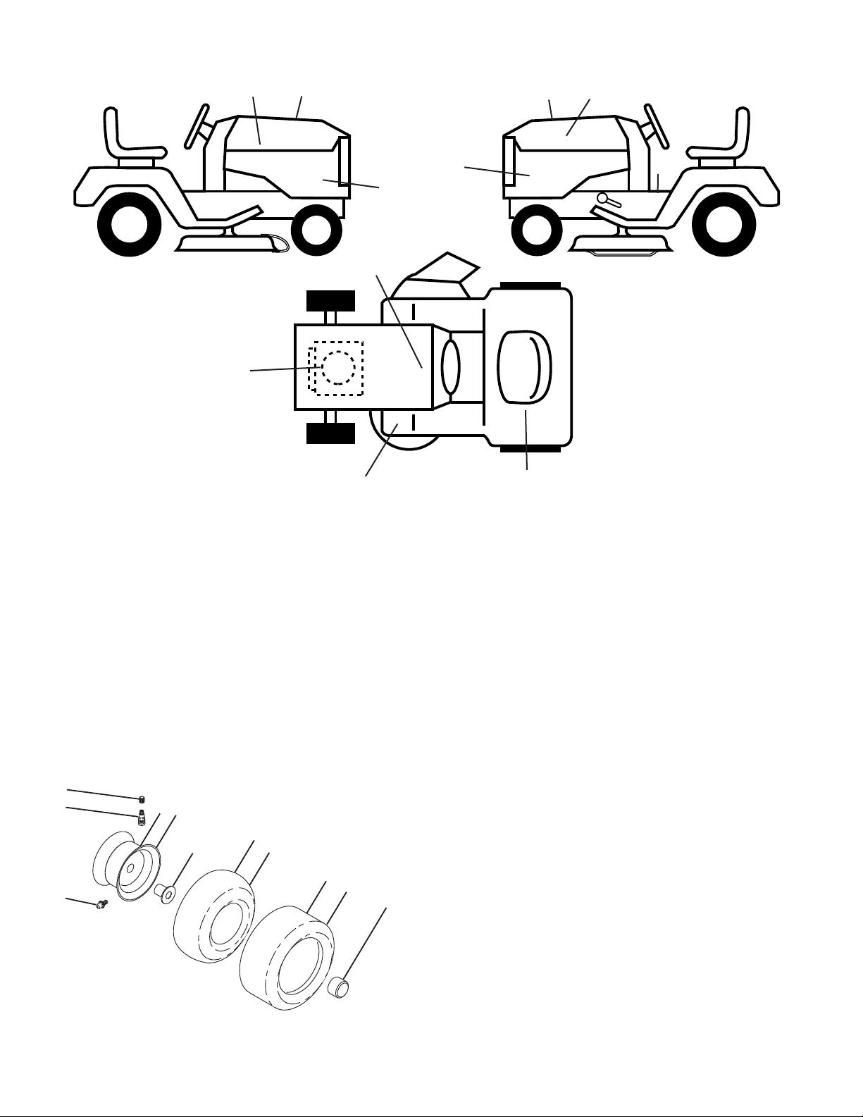
DECALS
16
15
17
16
6
KEY PART
NO. NO. DESCRIPTION
1 532 41 16-58 Decal, Operator’s
4 532 41 86-00 Decal, Pedal
5 532 42 62-09 Decal, Warning Reserve
6 532 43 29-18 Decal, Eng. H.P.
9 532 14 50-05 Decal, Battery Dnge/Poi
14 532 43 36-97 Decal, Panel Side
15 532 42 38-29 Decal, Cust. Resp.
16 532 42 91-96 Decal, Hood Logo
14
14
9
4
5
1
KEY PART
NO. NO. DESCRIPTION
17 532 43 35-02 Decal, Replacement
- - 532 16 69-60 Decal, Bypass
- - 532 40 17-71 Pad, Footrest, LH
- - 532 40 37-73 Pad, Footrest, RH
- - 532 43 26-53 Manual, Owner’s (Eng)
- - 532 43 27-50 Manual, Owner’s (Fr)
WHEELS AND TIRES
KEY PART
NO. NO. DESCRIPTION
1 532 05 91-92 Cap, Valve, Tire
2 532 06 51-39 Stem, Valve
3 532 18 18-39 Rim Assembly, Front
4 532 00 81-34 Tube, Front (Service Item Only)
5 532 16 10-24 Tire, Front
6 532 12 49-57 Fitting, Grease (Front Wheel Only)
7 532 12 49-59 Bearing, Flange (Front Wheel Only)
8 532 17 50-39 Cap, Axle (Front Wheel Only)
9 532 17 04-53 Tire, Rear
10 532 00 71-54 Tube, Rear (Service Item Only)
11 532 14 45-10 Rim Assembly, Rear
- - 532 14 43-34 Sealant, Tire (10 oz. Tube)
NOTE: All component dimensions given in U.S. inches
1 inch = 25.4 mm
28
Page 3
NOTES
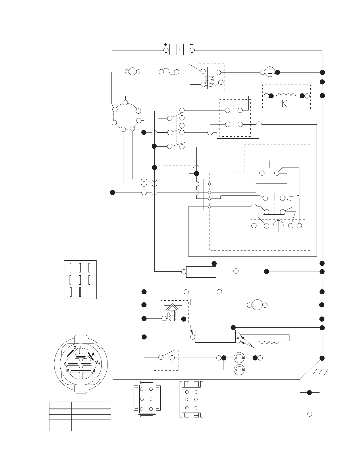
M
FUSE
STARTER
SOLENOID
BATTERY
ELECTRIC CLUTCH
CLUTCH/BRAKE
(PEDAL UP)
REVERSE SWITCH
(NOT IN REVERSE)
SEAT SWITCH
(NOT OCCUPIED)
SHORTING
CONNECTOR
CHASSIS
HARNESS
IGNITION
UNIT
HOUR
METER
REGULATOR
CHASSIS HARNESS
CONNECTOR
(MATING SIDE)
DASH HARNESS
CONNECTOR
(MATING SIDE)
LIGHT
SWITCH
HEADLIGHTS
STATOR
FUEL
LINE
FUEL SHUT-OFF
SOLENOID
(IF EQUIPPED)
JUNCTION
CONNECTOR
PTO SWITCH
(DISENGAGED)
S
M
B
G
L
2
3
1
6
A2
A1
M
6
3
52
41
6
5
4
3
2
1
SPARK
PLUGS GAP
(2 PLUGS ON
TWIN CYL. ENGINES)
28 VOLTS AC @ 3600 RPM (REGULATOR DISCONNECTED)
CHARGING SYSTEM OUTPUT
9-16AMPDC@3600 RPM
(OPTIONAL)
NON-REMOVABLE
CONNECTIONS
REMOVABLE
CONNECTIONS
WIRING INSULATED CLIPS
NOTE: IF WIRING INSULATED
CLIPS WERE REMOVED FOR
SERVICING OF UNIT, THEY
SHOULD BE RE-INSTALLED TO
PROPERLY SECURE YOUR
WIRING.
SCH12
IGNITION SWITCH
CIRCUITPOSITION
OFF
B+A1
RUN/OVERRIDE
B+S+A1START
M+G+A1
B+A1RUN
“MAKE”
L+A2
POWER OUTLET
(OPTIONAL)
12V
A
AMMETER
(OPTIONAL)
BLACK
BLACK /WHITE
ORANGE
RED
BROWN
BLUE
BLUE
BLACK
BLACK
BLACKBLACK
BLACK
BLACK
BLACK
BLACK
BLACK
BLACK
BLACK
RED
RED
RED
RED
WHITE
WHITE
WHITE
GRAY
GRAY
BLACK
BLACK
B
A
G
H
D
FC
E
PTO SWITCH
B
A
H
D
C
E
BLUE
BLACK
TRACTOR - MODEL NO. GTH27V52LS (96043009100), PRODUCT NO. 960 43 00-91
SCHEMATIC
29
Page 4
TRACTOR - MODEL NO. GTH27V52LS (96043009100), PRODUCT NO. 960 43 00-91
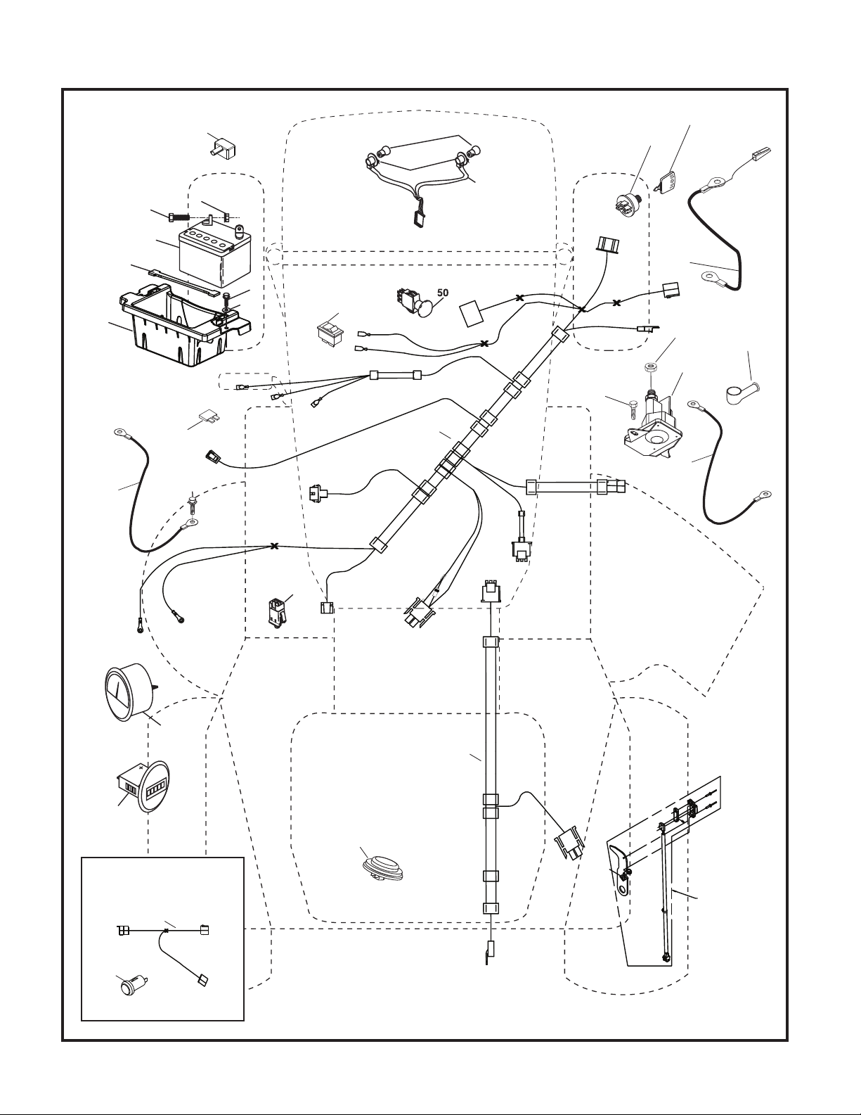
ELECTRICAL
T14S
90
79
2
27
22
30
21
1
33
91
24
99
100
8
34
27
42
43
41
26
40
25
28
55
0
60
AMPS
60
45
46
With 12V Outlet Option
103
59
16
71
29
141
30
Page 5

TRACTOR - MODEL NO. GTH27V52LS (96043009100), PRODUCT NO. 960 43 00-91
ELECTRICAL
KEY PART
NO. NO. DESCRIPTION
1 532 16 34-65 Battery
2 874 76 04-12 Bolt Hex Hd 1/4-20 unc x 3/4
8 532 18 64-91 Battery Box
16 532 17 61-38 Switch Interlock
21 532 18 37-59 Harness Socket Light
22 532 00 41-52 Bulb, Light #1156
24 532 40 02-53 Cable Battery
25 532 41 28-95 Cable Starter
26 532 17 51-58 Fuse
27 873 51 04-00 Nut Keps Hex 1/4-20 unc
28 532 14 54-91 Cable Ground 21” Blk 6 Ga.
29 532 40 15-45 Switch Seat
30 532 19 33-50 Switch Ign
33 532 41 19-35 Key/Chain
34 532 11 07-12 Switch Light/Reset
40 532 42 90-83 Harness EFM
41 817 72 04-08 Screw 1/4-20 unc x 1/2
42 532 13 15-63 Cover Terminal Red
43 532 19 25-07 Solenoid
45 532 42 52-70 Ammeter Round
46 532 42 52-71 Gauge Hourmeter
50 532 17 46-51 Switch PTO
55 817 06 05-12 Screw Thdrol 5/16-18 x 3/4
59 532 40 03-03 Outlet 12-Volt
71 532 19 42-76 Harness Ign
79 532 17 52-42 Socket Asm. Bulb Twistlock
90 532 40 07-24 Cover Terminal Battery
91 532 19 02-70 Strap Battery
99 817 67 04-12 Screw Hexwsh Thdrol 1/4-20 x 3/4
100 819 09 14-16 Washer 9/32 x 7/8 x 16 Ga.
103 532 42 17-47 Harness Pigtail 12V Outlet
141 532 42 12-25 Kit G700/G730 ROS
NOTE: All component dimensions given in U.S. inches
1 inch = 25.4 mm
31
Page 6
TRACTOR - MODEL NO. GTH27V52LS (96043009100), PRODUCT NO. 960 43 00-91
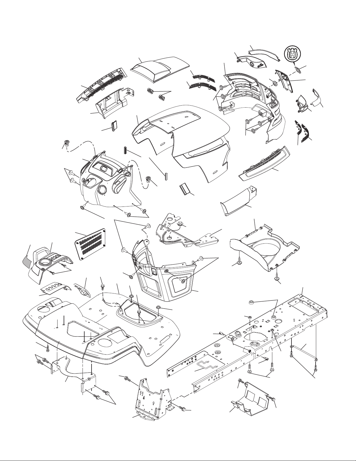
CHASSIS
15
18
208
130
298
202
209
3
238
207
211
25
181
176
203
5
206
204
210
212
214
130
14
234
137
221
162
189
199
196
178
162
161
36
176
176
37
194
36
176
181
194
177
234
182
228
175
176
130
194
236
205
150
130
235
236
180
217
58
chassis-tex_TEX GT HUSQ_84
159
189
228
165
183
159
159
2
152
159
68
32
Page 7

TRACTOR - MODEL NO. GTH27V52LS (96043009100), PRODUCT NO. 960 43 00-91
CHASSIS
KEY PART
NO. NO. DESCRIPTION
2 532 19 42-61 Drawbar
3 532 40 50-12 Logo Husq.
5 532 42 54-42 Dash
14 532 41 10-46 Hood
15 532 19 89-07 Lens LH
18 532 40 86-07 Grille Asm
25 532 19 89-06 Lens RH
36 817 06 05-12 Screw 5/16-18 x 3/4
37 532 40 18-25 Fender
58 532 19 43-14 Bracket Fender
68 817 49 05-08 Screw 5/16-18 x 1/2
130 532 41 63-58 Screw #10 x 0.750 BOS Thread
137 532 40 75-90 Bumper Dash
150 532 19 85-12 Duct Heat Hood
152 532 19 43-29 Shield Browning/Debris
159 817 00 06-12 Screw 3/8-16 x 3/4
161 532 40 18-26 Console Fuel Window
162 532 14 24-32 Screw Hex Wsh Hi-Lo 1/4 x 1/2
165 532 19 43-30 Bracket Support Tank
175 532 19 63-04 Crossmember
176 532 40 07-76 Screw 10-24 x 5/8 Wshd Qdrx
177 532 19 52-27 Bushing Steering
178 532 19 97-82 Cargo Asm. Net
180 532 19 42-60 Chassis
181 532 40 30-25 Bushing Mtg. Fender Crgo.
182 532 40 68-59 Dash Lower
183 874 52 05-20 Bolt 5/16-18 x 1-1/4
189 817 00 05-12 Screw 5/16-18 x 3/4
KEY PART
NO. NO. DESCRIPTION
194 873 90 05-00 Nut Lock Hex Flange 5/16-18
196 532 41 77-78 Console Asm. Deck Lift
199 532 19 82-59 Plate Deck Lift
202 532 40 30-48 Vent Side Hood RH
203 532 40 30-76 Vent Side Hood LH
204 532 41 66-13 Vent Asm Hood Top
205 532 40 17-09 Skirt Hood Side RH
206 532 40 17-11 Skirt Hood Side LH
207 532 19 71-98 Bezel RH
208 532 19 71-99 Bezel LH
209 532 19 91-30 Insert Hex Top RH
210 532 19 91-31 Insert Hex Top LH
211 532 19 91-32 Insert Hex Bottom RH
212 532 19 91-33 Insert Hex Bottom LH
214 532 19 91-45 Clip Retainer
217 532 40 91-67 Rod Pivot
221 532 19 89-09 Reflector LH
228 532 19 51-61 Stud Fastener
234 532 40 47-42 Bumper Hood
235 532 40 61-29 Spacer Fender
236 873 93 05-00 Nut Center Lock 5/16-18 unc
238 532 40 86-06 Trim Husq.
298 532 11 04-52 Nut Push
- - 532 43 18-82 Kit Gaurd Brush
NOTE: All component dimensions given in U.S. inches
1 inch = 25.4 mm
33
Page 8

TRACTOR - MODEL NO. GTH27V52LS (96043009100), PRODUCT NO. 960 43 00-91
DRIVE
184
42
69
33
145
221
220
9
3
74
70
74
56
35
64
188
49
186
7
187
51
2
116
160
203
167
160
159
15
49
189
190
50
51
52
51
221
213
209
29
15
306
48
160
92
207
161
163
26
206
211
125
286
153
215
125
116
80
208
114
285
125
121
197
211
196
125
125
214
284
210
222
166
73
drive-tex_G700_pedal_7
17
153
1
99
145
2
69
3
33
34
Page 9

TRACTOR - MODEL NO. GTH27V52LS (96043009100), PRODUCT NO. 960 43 00-91
DRIVE
KEY PART
NO. NO. DESCRIPTION
1 - - - - - - Transaxle, Hydro
G7-BCBB-1XDC-1FCA
2 532 00 70-70 Key 1/4 x 2.5
3 532 00 75-63 Washer Thrust Axle Hardened
7 532 19 98-37 Hub Asm. Wheel
9 532 14 00-80 Bolt Hub Wheel
15 819 13 13-16 Washer 13/32 x 13/16 x 16 Ga.
17 532 19 72-96 Spring, Brake
26 532 19 96-79 Spring Return Cruise
29 532 41 81-86 Rod, Brake
33 812 00 00-53 Ring E
35 532 19 95-91 Rod, Brake, Park
42 532 12 48-72 Cover, Foot Pedal
48 872 11 06-12 Bolt Carr Sh 3/8-16 x 1-1/2 Gr.5
49 872 11 06-14 Bolt
50 532 19 43-27 Pulley Idler Flat
51 873 90 06-00 Lock Nut 3/8-16
52 532 19 43-26 Idler V-Groove 910" Offset
56 532 42 08-07 V-Belt, Drive
64 532 19 78-65 Shaft Asm. Pedal Brake Control
69 532 12 38-00 Washer 1-1/32 x 1-5/8 x 16 Ga.
70 532 40 05-30 Console Asm
73 874 49 05-48 Bolt Hex 5/16-18 x 3 Gr. 5
74 532 14 24-32 Screw 1/4 x 1/2
80 532 41 81-84 Strap Torque
92 874 76 05-20 Bolt 5/16-18 x 1/2
99 532 41 81-88 Spring Bypass
114 873 80 05-00 Nut Lock Hex W/Ins. 5/16-18 unc
116 873 90 05-00 Nut Lock Hex Flange 5/16-18
121 532 17 56-11 Bracket Strap Torque
125 817 00 05-12 Screw 5/16-18 x 3/4
145 532 16 31-68 Washer Axle Flange
153 532 12 47-88 Retainer Spring
159 876 02 04-12 Pin Cotter 1/8 x 3/4
KEY PART
NO. NO. DESCRIPTION
160 532 16 94-84 Retainer Clip
161 532 10 57-09 Spring, Return, Clutch
163 532 41 81-85 Rod Pedal Control
166 532 42 91-64 Nut Push .625
167 532 40 52-57 Latch Brake Parking
184 532 40 31-18 Handle Parking Brake
186 532 19 43-21 Spacer Retainer
187 819 13 32-10 Washer
188 532 19 43-23 Link Clutch Ground Drive
189 532 40 75-04 Bellcrank Ground Drive
190 532 40 75-05 Keeper Bellcrank Ground Drive
196 817 00 06-16 Screw 3/8-16 x 1
197 532 19 97-69 Bracket Clutch Anti-Rotation
203 819 11 11-16 Washer 11/32 x 11/16 x 16 Ga.
206 532 19 78-67 Bracket Mount Latch Cruise
207 532 19 78-68 Latch Control Cruise
208 532 19 78-69 Gear Sector Control Cruise
209 532 19 95-92 Rod Control Cruise
210 532 19 78-60 Rocker Asm. Pedal Control
211 532 12 01-83 Bearing Nylon
213 532 40 31-19 Knob Control Cruise
214 532 41 68-63 Pedal Forward
215 532 40 17-23 Pedal Reverse
220 532 19 89-08 Reflector RH
221 532 40 31-87 Retainer Spring Clip Handle
222 879 21 20-10 Washer 21/32 x 1-1/4 x 10 Ga.
284 532 41 76-93 Nut U channel 1/4-20
285 532 41 77-65 Screw PHD 1/4-20 Box Drive
286 872 01 05-20 Bolt 5/16-18 x 2.50
306 876 02 04-16 Pin Cotter 1/8 x 1
NOTE: All component dimensions given in U.S. inches
1 inch = 25.4 mm
35
Page 10

TRACTOR - MODEL NO. GTH27V52LS (96043009100), PRODUCT NO. 960 43 00-91
ENGINE
30!2+ª!22%34%2ª+)4
ENGINETEX?BSCYL?
36
Page 11

TRACTOR - MODEL NO. GTH27V52LS (96043009100), PRODUCT NO. 960 43 00-91
ENGINE
KEY PART
NO. NO. DESCRIPTION
1 - - - - - - Engine B&S Model No. 44Q777-1406-B1
2 532 14 97-23 Muffler
9 532 40 86-67 Keeper Asm. Belt Engine
11 532 17 93-35 Clutch Electric
12 532 19 43-43 Pulley Engine
15 532 42 28-04 Tank Fuel
18 532 43 02-17 Cap Asm
20 532 42 43-41 Control Throttle
21 532 41 63-58 Screw #10 x 0.750 BOS Thread
28 532 40 11-35 Fuel Line
29 532 13 71-80 Spark Arrester Kit
37 532 12 34-87 Clamp Hose
41 532 12 61-97 Washer 1-1/2 OD x 15/32 ID x .250
42 810 04 07-00 Washer Lock 7/16
45 873 51 04-00 Nut Keps Hex 1/4-20 unc
62 532 14 66-29 Shield Heat Muffler
69 532 16 53-91 Gasket
70 532 15 99-55 Tube Exhaust LH
71 532 16 05-89 Tube Exhaust RH
79 532 18 39-06 Screw Socket HD 5/16-18 x 1
84 817 06 06-20 Screw 3/8-16 x 1-1/4
85 532 17 99-53 Bolt 7/16-20 x 3.75 Gr. 5
87 532 19 82-39 Bolt 5/16-18 unc x 1 w/Sems
90 817 00 06-16 Screw 3/8-16 x 1
91 532 18 74-95 Bushing
116 532 42 46-59 Knob Soft Touch
117 532 42 08-28 Valve Fuel Reserve
NOTE: All component dimensions given in U.S. inches
1 inch = 25.4 mm
For engine service and replacement parts, call the toll free
number for your engine manufacturer listed below:
Briggs & Stratton 1-800-233-3723
Engine Power Rating Information
The gross power rating for individual gas engine models is labeled in accordance with SAE (Society of Automotive Engineers) code J1940 (Small Engine Power & Torque Rating Procedure), and rating performance has been obtained and
corrected in accordance with SAE J1995 (Revision 2002-05). Torque values are derived at 3060 RPM; horsepower values
are derived at 3600 RPM. Actual gross engine power will be lower and is affected by, among other things, ambient operating conditions and engine-to-engine variability. Given both the wide array of products on which engines are placed and
the variety of environmental issues applicable to operating the equipment, the gas engine will not develop the rated gross
power when used in a given piece of power equipment (actual “on-site” or net power). This difference is due to a variety
of factors including, but not limited to, accessories (air cleaner, exhaust, charging, cooling, carburetor, fuel pump, etc.),
application limitations, ambient operating conditions (temperature, humidity, altitude), and engine-to-engine variability.
Due to manufacturing and capacity limitations, Briggs & Stratton may substitute an engine of higher rated power for this
Series engine.
37
Page 12

TRACTOR - MODEL NO. GTH27V52LS (96043009100), PRODUCT NO. 960 43 00-91
STEERING ASSEMBLY
26
45
51
21
16
13
64
28
54
63
69
68
steering-tex_STDHRS_11
28
22
59
50
58
70
50
60
35
19
4
61
63
15
65
13
66
54
13
8
53
65
9
8
7
2
6
67
14
55
78
67
62
9
8
14
7
55
6
5
15
38
Page 13

TRACTOR - MODEL NO. GTH27V52LS (96043009100), PRODUCT NO. 960 43 00-91
STEERING ASSEMBLY
KEY PART
NO. NO. DESCRIPTION
1 532 41 64-80 Wheel, Steering
2 532 19 59-68 Axle Asm., Front
4 532 40 30-89 Spindle Asm. LH
5 532 40 30-90 Spindle Asm. RH
6 532 12 49-31 Bearing, Race Thrust Harden
7 532 12 17-48 Washer 25/32 x 1-5/8 x 16 Ga.
8 812 00 00-29 Ring, Clip #T5304-75
9 532 12 12-32 Cap, Spindle
13 532 12 17-49 Washer 25/32 x 1-1/4 x 16 Ga.
14 810 04 06-00 Washer, Lock Hvy Hlcl Spr 3/8
15 873 54 06-00 Nut, Crown Lock 3/8-24 unf
16 532 40 82-19 Shaft Steering
19 532 19 47-29 Plate Steering
21 532 18 67-37 Adapter, Wheel Steering
22 532 42 05-37 Steering Support Lower
26 532 41 59-87 Insert, Wheel Steering
28 817 00 06-12 Screw 3/8-16 x 3/4
35 532 19 47-32 Gear, Sector Plate
45 819 18 38-12 Washer 9/16 x 2-3/8 x 12 Ga.
50 873 90 06-00 Nut Lock Flange 3/8-16 unc
51 873 94 08-00 Nut Hex Jam Toplock 1/2-20 unf
53 532 18 89-67 Washer Hardened .793 x 1.637 x .060
54 874 76 06-36 Bolt Hex 3/8-16 unc x 2-1/4
55 532 41 47-36 Bolt Hex 3/8-16 unc x 2-1/4
58 532 19 47-47 Bolt Shoulder Sector Pivot CFM
59 532 19 47-48 Washer Thrust Sector Steering
60 873 97 10-00 Nut Flange Lock 5/8-11
61 532 19 47-40 Draglink, LH
62 532 19 47-41 Draglink, RH
63 817 00 05-12 Screw 5/16-18 x 3/4
64 532 19 98-49 Retainer Clip Spring Steering
65 532 19 47-34 Brace Axle Front
66 871 02 07-48 Bolt Hex Fghd 7/16-14 x 3 Serr
67 532 19 47-37 Bushing PM Front Axle
68 873 90 07-00 Nut Lock Flange 7/16-14 Gr. 5
69 532 19 91-62 Washer 1.5 x .505 x .118
70 532 19 61-97 Bracket Deck Susp. Front
78 532 05 70-79 Washer Thrust
NOTE: All component dimensions given in U.S. inches
1 inch = 25.4 mm
39
Page 14

TRACTOR - MODEL NO. GTH27V52LS (96043009100), PRODUCT NO. 960 43 00-91
MOWER DECK
52
37
45
46
16
43
39
27
15
36
57
47
56
55
18
17
16
33
25
51
34
50
24
35
33
49
32
53
19
31
30
54
5
4
21
6
3
59
44
20
22
1
48
24
23
38
52F-tex_elec_3
61
10
62
63
58
11
13
29
40
2
28
9
8
60
7
14
12
Page 15

TRACTOR - MODEL NO. GTH27V52LS (96043009100), PRODUCT NO. 960 43 00-91
MOWER DECK
KEY PART
NO. NO. DESCRIPTION
1 575 43 80-03 Deck w/ Decals 52"
2 539 11 21-70 Housing Assembly
3 539 10 75-20 Washer-Spacer
4 532 10 75-21 Pulley, Mandrel
5 539 10 75-90 Nut, 9/16 Top Center Lock
6 539 10 76-30 Screw, Washer Head
7 532 11 07-33 Discharge Chute, 52"
8 532 11 07-35 Spring - Torsion
9 532 11 07-36 Pin, Clevis 5/16 x 5.19
10 574 87 08-01 Blade, 16-1/4"
11 539 10 75-22 Bolt, 7/16, Assy Blade
12 574 87 50-02 Confinement Plate
13 539 99 07-99 Rhsnb 5/16-18 x 5/8 Gr 5
14 539 99 07-17 Nut 5/16-18 Hex Nyloc
15 532 19 51-61 Stud, Fasten w/ Anti- Rotate
16 539 11 28-99 Nut 5/16-18 Hex Flange Nyloc
17 532 19 61-04 Pulley, Idler Spec. Hub
18 574 84 18-02 Arm, Idler, Blk
19 532 17 79-68 Pulley, Idler
20 539 13 27-28 Pulley, Idler
21 575 22 45-01 Idler Bushing
22 539 10 76-10 Wheel, Gauge
23 539 10 76-08 Bolt, Shoulder
24 521 99 65-01 Nut 3/8-16 Hex Flg Nyloc
25 575 22 47-02 Shield, Belt LH
27 539 10 47-63 Retainer 5/16c U Type
28 539 10 82-71 Hcs 3/8-16 x 3-1/2 Gr 5
29 539 10 65-04 Heavy Washer
30 539 99 05-17 Washer, 3/8 Flat Std
31 539 97 69-79 Nut 3/8-16 Hex Nyloc
32 539 99 09-23 Rhsnb 3/8-16 x 1-3/4 Gr 5
33 539 10 48-64 Washer, 7/16 Flat
34 532 17 85-15 Washer, Flat Hardened
KEY PART
NO. NO. DESCRIPTION
35 539 11 91-24 Nut, 7/16-14 Hex Nyloc
36 532 19 51-85 Arm, Susp., Rear
37 539 11 36-21 Sb 3/8-16 x 3/8 Skt Hd
38 539 99 01-22 Washer, 3/8 Sae Flt
39 539 20 02-82 Nut, 3/8-16 Hex Jam Nyloc
43 539 99 06-92 Washer, 5/16 Std Flt
44 575 32 00-02 Shield, Belt RH
45 539 99 02-09 Hcs 5/16-18 x 1 Gr 5
46 539 99 01-87 Wash 5/16 Slw
47 539 10 57-43 Decal, No Step
48 539 11 32-24 Decal, Warning
49 532 19 87-85 Decal, Deck Sch
50 532 41 55-98 Washout Port
51 539 10 84-61 Bolt, 1/4-20 x 1/2
52 539 10 48-70 Hcs 7/16-14 x 2-1/2 Gr 5
53 574 84 56-03 Belt, Deck
54 575 22 43-01 Guard, Belt
55 539 11 55-74 Eyebolt 5/16 x 3-1/2
56 539 99 05-85 Nut 5/16-18 Hex Whizlk
57 539 10 68-50 Spring
58 539 11 20-50 Ball Bearing
59 575 35 29-01 Pulley
60 532 16 94-84 Clip Retainer
61 532 40 48-51 Rod Anti-Sway
62 819 13 13-12 Washer 13/32 x 13/16 x 12 Ga.
63 532 19 42-08 Pin Cotter 5/16 Bow Tie Lock
- - 575 01 58-03 Mower Deck Complete
NOTE: All component dimensions given in U.S. inches
1 inch = 25.4 mm
41
Page 16

TRACTOR - MODEL NO. GTH27V52LS (96043009100), PRODUCT NO. 960 43 00-91
SEAT ASSEMBLY
1
44
41
40
10
21
8
8
8
7
7
8
6
37
6
2
37
43
seat-tex_6.5SL_3
KEY PART
NO. NO. DESCRIPTION
1 532 42 40-73 Seat
2 532 18 01-66 Bracket Pivot Fender
3 532 14 06-75 Strap, Asm Fender
6 873 80 06-00 Nut, Lock w/Ins. 3/8-16 unc
7 532 12 41-81 Spring, Seat Cprsn
8 532 17 18-77 Bolt 5/16-18 unc x 3/4 w/Sems
10 532 19 69-77 Pan, Seat
21 532 17 18-52 Bolt, Shoulder 5/16-18
21
3
KEY PART
NO. NO. DESCRIPTION
37 873 80 05-00 Nut, Lock 5/16-18 unc
40 532 42 59-19 Handle Slide Seat
41 532 19 82-00 Spring Latch Seat
43 874 76 06-12 Bolt Fin Hex 3/8-16 unc x 3/4
44 819 13 38-12 Washer 13/32 x 2-3/8 x 12 Ga.
NOTE: All component dimensions given in U.S. inches
1 inch = 25.4 mm
42
Page 17

TRACTOR - MODEL NO. GTH27V52LS (96043009100), PRODUCT NO. 960 43 00-91
MOWER LIFT
LIFTTEX?
KEY PART
NO. NO. DESCRIPTION
2 532 42 20-27 Shaft Asm., Lift
3 532 19 52-30 Lever Asm., Lift RH
7 532 41 15-55 Grip, Lever
10 532 19 63-14 Spring Torsion
41 532 17 59-94 Nut Lift Link
87 532 19 42-09 Pin Cotter 7/16 Bow Tie Lock
88 532 19 53-04 Spring Lift Assist
89 819 19 19-12 Washer Clear Zinc
KEY PART
NO. NO. DESCRIPTION
91 532 40 34-07 Link Lift Susp Mower Rear
96 532 19 52-63 Bushing Spherical
97 817 00 06-12 Screw 3/8-16 x .75
98 574 82 25-01 Link Lift Susp. Front Mower
114 873 36 07-00 Nut Jam 7/16-20
NOTE: All component dimensions given in U.S. inches
1 inch = 25.4 mm
43
Page 18

SERVICE NOTES
44
Page 19

SERVICE NOTES
45
Page 20

SERVICE NOTES
46
Page 21

15 DEGREES MAX.
FOLD ALONG DOTTED LINE
THIS IS A 15 DEGREE SLOPE
ONLY RIDE UP AND DOWN HILL,
NOT ACROSS HILL
SUGGESTED GUIDE FOR SIGHTING SLOPES FOR SAFE OPERATION
WARNING: To avoid serious injury, operate your tractor up and
down the face of slopes, never across the face. Do not mow
slopes greater than 15 degrees. Make turns gradually to prevent
tipping or loss of control. Exercise extreme caution when
changing direction on slopes.
1. Fold this page along dotted line indicated above.
2. Hold page before you so that its left edge is vertically parallel to a tree
trunk or other upright structure.
3. Sight across the fold in the direction of hill slope you want to measure.
4. Compare the angle of the fold with the slope of the hill.
47
Page 22

04.05.10 CL Printed in the U.S.A.
 Loading...